Embed Size (px)
Citation preview
AC (AD) 14
AERODROME MAINTENANCE MANUAL
First Edition2012
CIVIL AVIATION AUTHORITY BANGLADESH
Page 1 of 64
LIST OF EFFECTIVE PAGES
Chapter Pages Edition/ Version Date of Issue
Page 2 of 64
RECORD OF AMENDMENTS
Edition/ VersionNumber Chapter Changed Pages Replaced Signature Date
Page 3 of 64
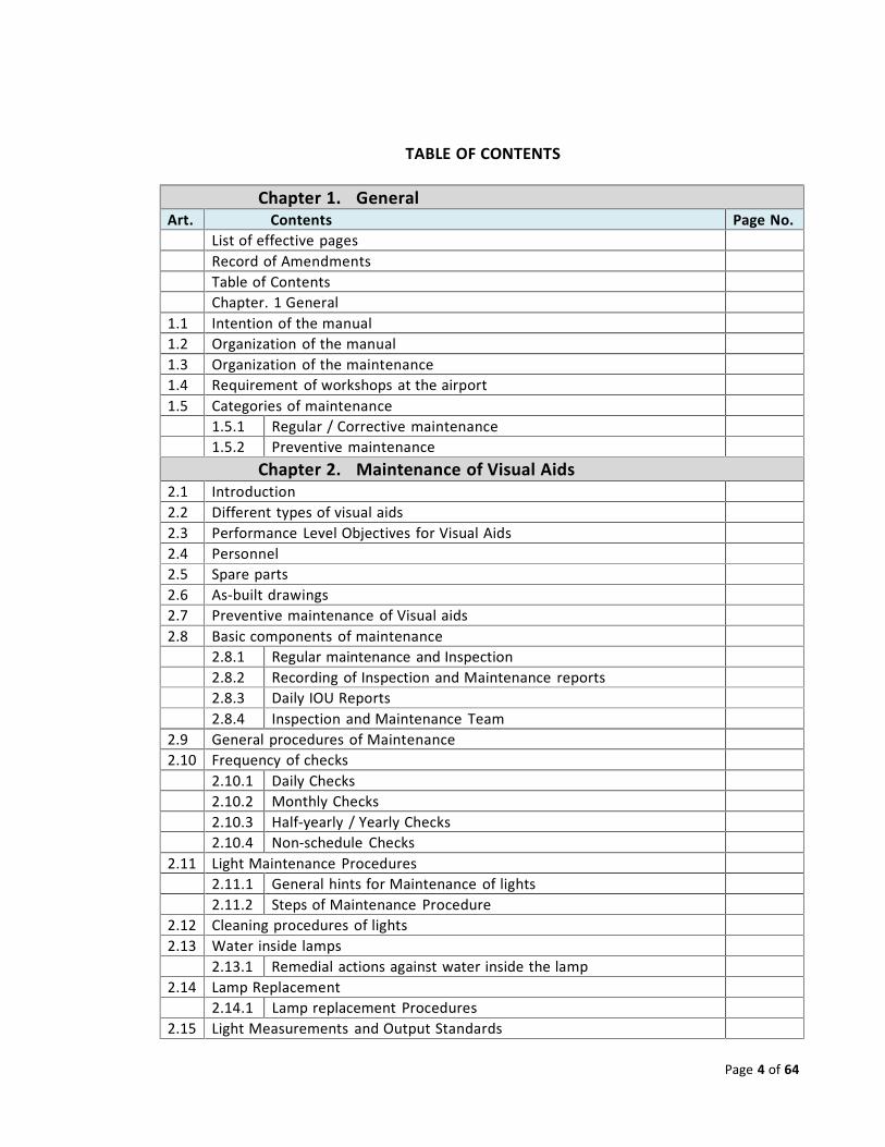
TABLE OF CONTENTS
Chapter 1. GeneralArt. Contents Page No.
List of effective pagesRecord of AmendmentsTable of ContentsChapter. 1 General
1.1 Intention of the manual1.2 Organization of the manual1.3 Organization of the maintenance1.4 Requirement of workshops at the airport1.5 Categories of maintenance
1.5.1 Regular / Corrective maintenance1.5.2 Preventive maintenance
Chapter 2. Maintenance of Visual Aids2.1 Introduction2.2 Different types of visual aids2.3 Performance Level Objectives for Visual Aids2.4 Personnel2.5 Spare parts2.6 As‐built drawings2.7 Preventive maintenance of Visual aids2.8 Basic components of maintenance
2.8.1 Regular maintenance and Inspection2.8.2 Recording of Inspection and Maintenance reports2.8.3 Daily IOU Reports2.8.4 Inspection and Maintenance Team
2.9 General procedures of Maintenance2.10 Frequency of checks
2.10.1 Daily Checks2.10.2 Monthly Checks2.10.3 Half‐yearly / Yearly Checks2.10.4 Non‐schedule Checks
2.11 Light Maintenance Procedures2.11.1 General hints for Maintenance of lights2.11.2 Steps of Maintenance Procedure
2.12 Cleaning procedures of lights2.13 Water inside lamps
2.13.1 Remedial actions against water inside the lamp2.14 Lamp Replacement
2.14.1 Lamp replacement Procedures2.15 Light Measurements and Output Standards
Page 4 of 64
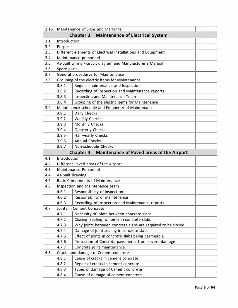
2.16 Maintenance of Signs and MarkingsChapter 3. Maintenance of Electrical System
3.1 Introduction3.2 Purpose3.3 Different elements of Electrical Installations and Equipment3.4 Maintenance personnel3.5 As‐built wiring / circuit diagram and Manufacturer’s Manual3.6 Spare parts3.7 General procedures for Maintenance3.8 Grouping of the electric items for Maintenance
3.8.1 Regular maintenance and Inspection3.8.2 Recording of Inspection and Maintenance reports3.8.3 Inspection and Maintenance Team3.8.4 Grouping of the electric items for Maintenance
3.9 Maintenance schedule and Frequency of Maintenance3.9.1 Daily Checks3.9.2 Weekly Checks3.9.3 Monthly Checks3.9.4 Quarterly Checks3.9.5 Half‐yearly Checks3.9.6 Annual Checks3.9.7 Non‐schedule Checks
Chapter 4. Maintenance of Paved areas of the Airport4.1 Introduction4.2 Different Paved areas of the Airport4.3 Maintenance Personnel4.4 As‐built drawing4.5 Basic Components of Maintenance4.6 Inspection and Maintenance team
4.6.1 Responsibility of inspection4.6.2 Responsibility of maintenance4.6.3 Recording of Inspection and Maintenance reports
4.7 Joints in Cement Concrete4.7.1 Necessity of joints between concrete slabs4.7.2 Closing (sealing) of joints in concrete slabs4.7.3 Why joints between concrete slabs are required to be closed4.7.4 Damage of joint sealing in concrete slabs4.7.5 Effect of joints in concrete slabs being permeable4.7.6 Protection of Concrete pavements from severe damage4.7.7 Concrete joint maintenance
4.8 Cracks and damage of Cement concrete4.8.1 Cause of cracks in cement concrete4.8.2 Repair of cracks in cement concrete4.8.3 Types of damage of Cement concrete4.8.4 Cause of damage of cement concrete
Page 5 of 64
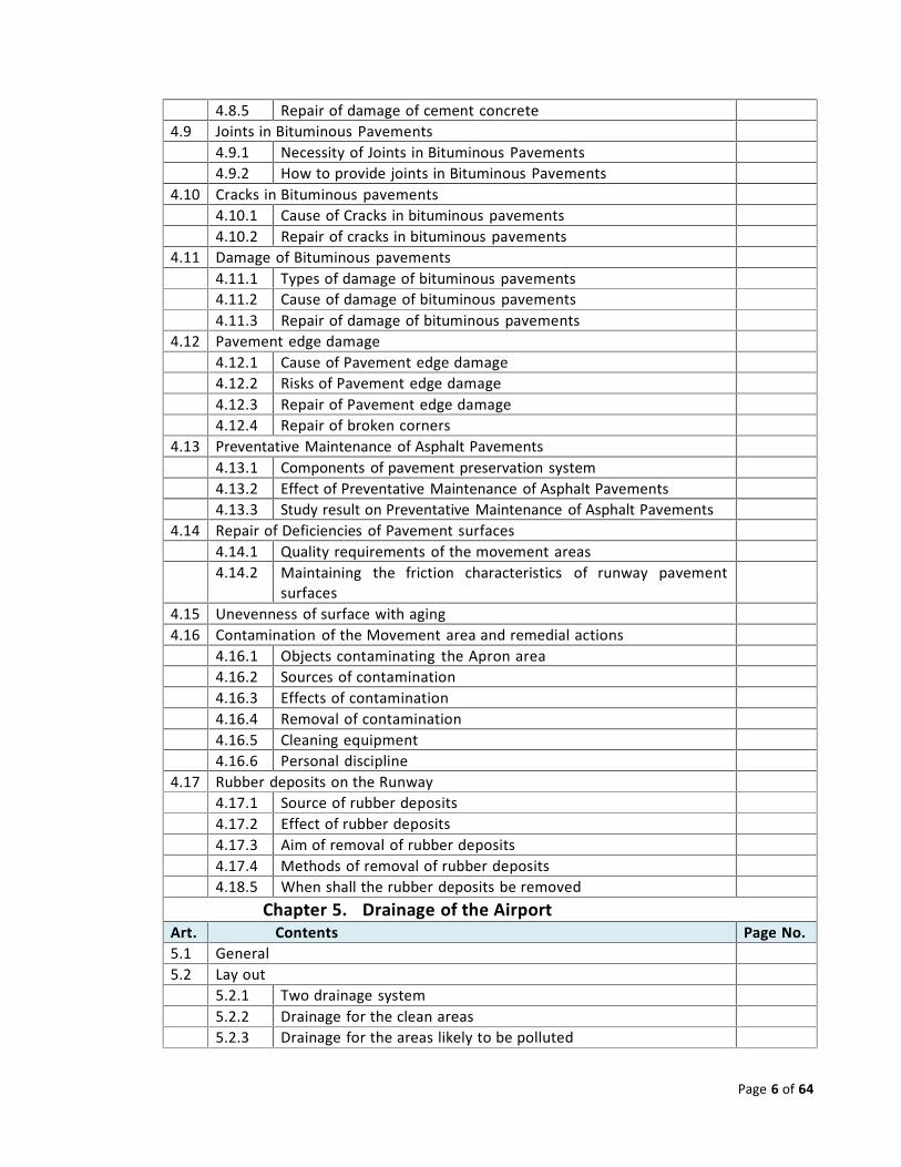
4.8.5 Repair of damage of cement concrete4.9 Joints in Bituminous Pavements
4.9.1 Necessity of Joints in Bituminous Pavements4.9.2 How to provide joints in Bituminous Pavements
4.10 Cracks in Bituminous pavements4.10.1 Cause of Cracks in bituminous pavements4.10.2 Repair of cracks in bituminous pavements
4.11 Damage of Bituminous pavements4.11.1 Types of damage of bituminous pavements4.11.2 Cause of damage of bituminous pavements4.11.3 Repair of damage of bituminous pavements
4.12 Pavement edge damage4.12.1 Cause of Pavement edge damage4.12.2 Risks of Pavement edge damage4.12.3 Repair of Pavement edge damage4.12.4 Repair of broken corners
4.13 Preventative Maintenance of Asphalt Pavements4.13.1 Components of pavement preservation system4.13.2 Effect of Preventative Maintenance of Asphalt Pavements4.13.3 Study result on Preventative Maintenance of Asphalt Pavements
4.14 Repair of Deficiencies of Pavement surfaces4.14.1 Quality requirements of the movement areas4.14.2 Maintaining the friction characteristics of runway pavement
surfaces4.15 Unevenness of surface with aging4.16 Contamination of the Movement area and remedial actions
4.16.1 Objects contaminating the Apron area4.16.2 Sources of contamination4.16.3 Effects of contamination4.16.4 Removal of contamination4.16.5 Cleaning equipment4.16.6 Personal discipline
4.17 Rubber deposits on the Runway4.17.1 Source of rubber deposits4.17.2 Effect of rubber deposits4.17.3 Aim of removal of rubber deposits4.17.4 Methods of removal of rubber deposits4.18.5 When shall the rubber deposits be removed
Chapter 5. Drainage of the AirportArt. Contents Page No.5.1 General5.2 Lay out
5.2.1 Two drainage system5.2.2 Drainage for the clean areas5.2.3 Drainage for the areas likely to be polluted
Page 6 of 64
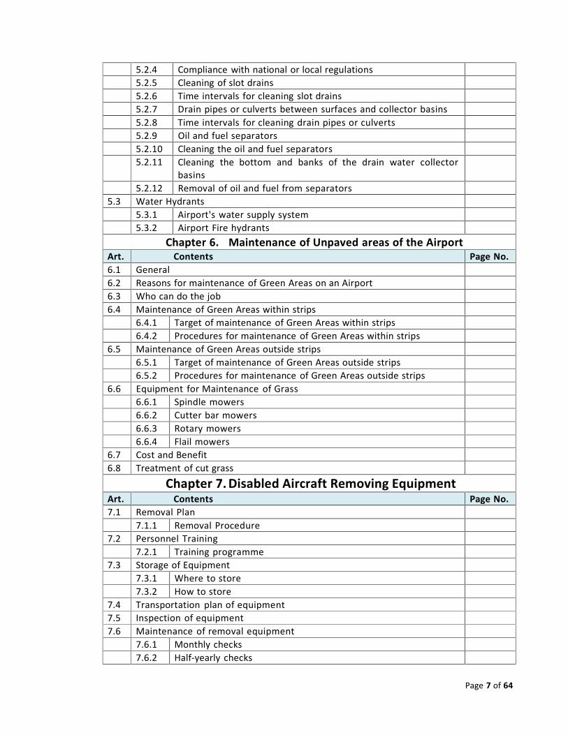
5.2.4 Compliance with national or local regulations5.2.5 Cleaning of slot drains5.2.6 Time intervals for cleaning slot drains5.2.7 Drain pipes or culverts between surfaces and collector basins5.2.8 Time intervals for cleaning drain pipes or culverts5.2.9 Oil and fuel separators5.2.10 Cleaning the oil and fuel separators5.2.11 Cleaning the bottom and banks of the drain water collector
basins5.2.12 Removal of oil and fuel from separators
5.3 Water Hydrants5.3.1 Airport's water supply system5.3.2 Airport Fire hydrants
Chapter 6. Maintenance of Unpaved areas of the AirportArt. Contents Page No.6.1 General6.2 Reasons for maintenance of Green Areas on an Airport6.3 Who can do the job6.4 Maintenance of Green Areas within strips
6.4.1 Target of maintenance of Green Areas within strips6.4.2 Procedures for maintenance of Green Areas within strips
6.5 Maintenance of Green Areas outside strips6.5.1 Target of maintenance of Green Areas outside strips6.5.2 Procedures for maintenance of Green Areas outside strips
6.6 Equipment for Maintenance of Grass6.6.1 Spindle mowers6.6.2 Cutter bar mowers6.6.3 Rotary mowers6.6.4 Flail mowers
6.7 Cost and Benefit6.8 Treatment of cut grass
Chapter 7. Disabled Aircraft Removing EquipmentArt. Contents Page No.7.1 Removal Plan
7.1.1 Removal Procedure7.2 Personnel Training
7.2.1 Training programme7.3 Storage of Equipment
7.3.1 Where to store7.3.2 How to store
7.4 Transportation plan of equipment7.5 Inspection of equipment7.6 Maintenance of removal equipment
7.6.1 Monthly checks7.6.2 Half‐yearly checks
Page 7 of 64
Page 8 of 64
7.6.3 Yearly checks7.7 Test run of the equipment
Chapter 8. Maintenance of Equipment and Vehicles8.1 General
8.1.1 RFF Operation vehicles8.1.2 Passenger, Freight and Ground handling vehicles
8.2 Principles of organization of maintenance of vehicles8.2.1 Reasons for providing workshops at the airport8.2.2 Reasons for providing airport‐owned workshops
8.2.3 Reasons for contracting with maintenance companies outsidethe airport
8.3 Schedule of Vehicle Maintenance8.3.1 Basis of preparing the Vehicle Maintenance Schedule8.3.1.1 Schedule on the basis of kms run8.3.1.2 Schedule on the basis of hours operated
8.3.1.3 Fixed Interval or Time based schedule i.e. schedule on the basisof Months or year
8.3.2 Categorization of Vehicle for Maintenance purpose8.3.3 Advantages of Fixed Interval or Time based schedules8.3.4 Defining the maintenance intervals8.3.5 Determining factors of maintenance schedules8.3.6 Servicing of radio‐telecommunication equipment8.3.7 Inspections and maintenance
Chapter 1: General
1.1 Intention of the Manual: 25 Jan.2012
Efficiency and safety of operation at an airport can only be expected from facilities that are ingood operational condition. Proper maintenance is the only key to keep the installations andfacilities of an airport in good condition. Maintenance also minimizes wear and tear, thuscontrolling and extending considerably the life span of technical components. In this respectmaintenance becomes an economic requirement to keep investment and capital costs for theaeronautical infrastructure within acceptable limits.

Page 9 of 64
1.1.1 The manual is intended to give guidance to aerodrome operators on planning andconducting maintenance work on the airport. The guidance has been developed on the basis ofrelated ICAO Documents which, in turn, were developed from various airport operators'practices and reflects long‐term experience in the field of airport operation. Since wear andsensitivity of any technical component depend on material, utilization, age, climate and otherenvironmental conditions, none of the recommendations on the type and intervals ofmaintenance action described in this manual should be considered a specification.Maintenance work shall be planned on the basis of local needs, experience andrecommendations of manufacturers of components and be carried out as per the approval ofthe appropriate authority.
1.2 Organization of the Manual: 25 Jan.2012
1.2.1 This manual is organized in such a way as to cover primarily the airport maintenancetasks required for maintaining safe aircraft operation during the landing, taxi and take‐offphases. In addition, some of the maintenance tasks supporting the airport efficiency have beenincluded.
1.2.2 The requirements for safety reasons dominate the first part of the manual'scontents, wherein the maintenance of visual aids, of electrical infrastructure, of pavements, ofunpaved areas and of the drainage system is dealt with. Availability of suitable equipment isthe tool for complying with the maintenance requirements of fixed facilities. Aircraft removalequipment represents a very special type of airport equipment. The material in this manual iscomplementary to the Airport Services Manual, Part 5, which deals with removal procedures.
1.3 Organization of the Maintenance: 25 Jan.2012
1.3.1 Inspection is very vital part of maintenance. It comprises all measures to check andevaluate the operating condition including spontaneous and scheduled checks. Scheduledchecks are carried out in accordance with a plan specifying the preparation of the check, thesort of check, the report on the result and the evaluation of the results. From the evaluationsthe operator decides whether or not extra servicing or even repair has to be undertaken.
1.3.2 A fundamental task of the maintenance organization is to translate the maintenancerequirements into man/hours and monetary value. This evaluation is the basis of staffingbudget planning. It is, furthermore, a tool for decision‐making when contracting third partiesfor maintenance tasks instead of employing extra personnel.
1.3.3 Computer assistance can be helpful and economical if the volume of maintenance ishigh. The computer is particularly capable of controlling preventive maintenance tasks typicalof electrical systems and machines. Furthermore, evaluation of the aging of inventory and ofmaintenance budget control can be facilitated by suitable computer programmes. Thecomputer is less effective for maintenance control of buildings and pavements, where repairwork upon notice will always prevail.
Page 10 of 64
1.3.4 Management should check the work carried out against scheduled maintenancetasks and thereby achieve the full control of the progress of maintenance and budget.Compliance reports are the feedback and have to be recorded, as well as observations on anyreported deficiencies.
1.3.5 Updated maintenance programmes will allow:a. appropriate;b. compliance with the recorded maintenance needs; andc. flexibility as to the timing of action when unexpected circumstances have
affected the planned schedule.
1.3.6 All maintenance programmes should be "screened" once a year, preferably at thetime of budget planning. It is useful not only to rely on recorded data but to inspect thecondition of all major objects at that time. In contrast to machines, whose operating hours givea good measure of wear, the deterioration of buildings is more dependent on weathering,utilization under heavy load, concealed construction deficiencies or other unpredictablesources of damage.
1.4 Requirement of workshops at the airport:
To ensure the whole airport's smooth operation the provision of workshops at the airport isnecessary from both an operational and economic standpoint. The size of the workshop andtypes of equipments to be available will of course depend on
a. the volume of maintenance to be done at the airport;b. the availability of skilled maintenance personnel; andc. availability of close‐to‐airport workshops or craftsmen that may be used for
maintenance work on contract basis;d. compliance with airport emergency plan; ande. economic aims.
A sound balance between the capacity of the airport's basic maintenance workforce and theirsystem to comply with peak and emergency workloads is important for an economic airportoperation.
1.5 Categories of maintenance:There are two categories of maintenance, namely‐
a) Corrective / Regular Maintenance,b) Preventive Maintenance.
1.5.1 Regular / Corrective maintenance:Corrective maintenance can be defined as the maintenance which is required to bring an itemback to working order when it has failed or worn out. Corrective maintenance shall be carriedout on items where‐
a) the consequences of failure or wearing out are not very significant, andb) the cost of corrective maintenance is not greater than preventive maintenance.
Page 11 of 64
Corrective Maintenance activity will consist of repair, restoration or replacement ofequipment/ item. This activity will be the result of a regular inspection, which identifies thefailure in time for corrective maintenance to be planned, scheduled and effected.
1.5.2 Preventive maintenance:Preventative maintenance is the maintenance which is carried out to prevent an item failing orwearing out. Preventive maintenance shall be implemented by providing systematicinspection, detection and prevention of incipient failure. Preventive maintenance shall becarried out on items where‐
a) the consequences of failure or wearing out are significant, andb) the cost of corrective maintenance is greater than preventive maintenance.
The items falling under preventive maintenance would be e.g. lift, fire alarms, monitoringlamps for important equipment, electricity supply etc.
Chapter 2: Maintenance of Visual Aids2.1 Introduction:The basic purpose of visual aid systems is to aid in the safe operation of aircraft. Therefore, thehighest standards of maintenance are required. Once a system has been installed, its usefulnessis dependent on its service‐ability which in turn depends upon the effectiveness of themaintenance work carried out. Annex 14, Chapter 1 defines a light to have failed when its lightoutput falls below 50 per cent of that specified for a new light. The loss of in light output can bedue to the following two causes:‐
a. Contaminants outside and inside the light unit, andb. Degradation of the lamp and optical system due to aging.
The light can and should be restored to its original condition by cleaning or replacing the lampand any parts which have apparently become degraded. For this purpose it is essential toestablish a comprehensive routine maintenance system for servicing lights and other equipmentso that the installation complies with the specified requirements. Reference is made to Annex14, Chapter 9.
2.2 Different types of Visual Aids:
Different types of visual aids used at airports are as follows:a. Runway edge lights , center line lights, touch‐down zone lights, threshold lights,
stop bar lights, runway end lights etc.b. Taxiway edge lights, center line lights, taxi stop bar lights etc.c. High intensity approach lights, low intensity approach lights, strobe lights, VASI /
PAPI etc.
Page 12 of 64
d. Aerodrome beacon, wind direction indicators, obstruction lights etc.e. Markings and signs etc.
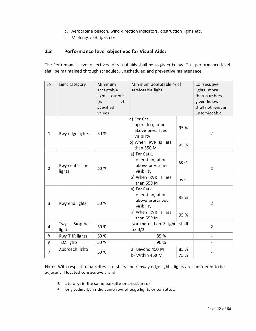
2.3 Performance level objectives for Visual Aids:
The Performance level objectives for visual aids shall be as given below. This performance levelshall be maintained through scheduled, unscheduled and preventive maintenance.
SN Light category Minimumacceptablelight output(% ofspecifiedvalue)
Minimum acceptable % ofserviceable light
Consecutivelights, morethan numbersgiven below,shall not remainunserviceable
1 Rwy edge lights 50 %
a) For Cat‐1operation, at orabove prescribedvisibility
95 %2
b) When RVR is lessthan 550 M 95 %
2 Rwy center linelights 50 %
a) For Cat‐1operation, at orabove prescribedvisibility
85 %2
b) When RVR is lessthan 550 M
95 %
3 Rwy end lights 50 %
a) For Cat‐1operation, at orabove prescribedvisibility
85 %2
b) When RVR is lessthan 550 M 95 %
4 Twy Stop‐barlights 50 % Not more than 2 lights shall
be U/S. 2
5 Rwy THR lights 50 % 85 % ‐6 TDZ lights 50 % 90 % ‐
7 Approach lights 50 % a) Beyond 450 M 85 % ‐b) Within 450 M 75 %
Note: With respect to barrettes, crossbars and runway edge lights, lights are considered to beadjacent if located consecutively and:
¾ laterally: in the same barrette or crossbar; or¾ longitudinally: in the same row of edge lights or barrettes.
Page 13 of 64
2.4 Personnel:
Electricians to be entrusted with the task of maintenance of lighting aids shall have the followingqualifications / qualities:
a. Be experienced with high voltage series circuits and lighting;b. Be fully acquainted with the work to be done;c. Be present or available on call during the operating hours of the airport to correct
any deficiencies that might develop;d. Be provided with appropriate training to maintain their competence and to keep
them abreast of new developments.
2.5 Spare parts:An adequate stock of spare parts should be available. The required level of stock will depend onthe following criteria:‐
a. Rate of consumption of the items;b. Time required to get the resupply of the items;c. Shelf life of the items.
2.6 As‐built drawing:A set of as‐built drawings shall be kept readily available in the Maintenance unit. The as‐builtdrawings shall be kept in the following manner:‐
a. Drawings shall be kept in the Maintenance unit and in the concerned Engineer’soffice;
b. Drawings must be kept up to date and any changes at site shall be reflected immediatelyon these drawings.
c. The completeness and the accuracy of all circuit diagrams, drawings anddescriptions shall be checked at least annually.
2.7 Preventive maintenance of Visual aids:
A system of preventive maintenance of visual aids shall be employed to ensure lighting andmarking system reliability. Procedures of preventive maintenance shall be as follows:‐
a. Light bulbs shall be considered unserviceable and be replaced when theirbrightness falls below 50% of normal value.
b. The specifications from the Manufacturers regarding the normal life time of all theitems of visual aids, shall be made available with the maintenance personnel, andlight bulbs shall be replaced after 90% of the manufacturer’s prescribed life timehas elapsed.
Page 14 of 64
c. In case when manufacturer’s specification is not available, light bulbs shall bereplaced after 90% of the average life time of the bulbs has elapsed.
d. Light fittings, fasteners and their supporting structures which may be damaged byrust shall be painted annually. Preferable period for such work shall be betweenJanuary and April each year.
e. Cable lives of all concerned sections of visual aids shall be verified and cables shallbe replaced whenever there is any threat to the system to be hampered fordamage of cables due to aging.
f. Functions of all other items shall be closely monitored and shall be replacedwhenever there is any threat to the system to be hampered due to aging of thoseitems.
2.8 Basic components of maintenance:Maintenance includes measures to keep or restore the operational function as well as measuresto check and to evaluate the present function of an element. The basic components ofmaintenance are:
a. Inspection/ Monitoring;(The unserviceable lights can be identified more easily during night inspections,and of course, possible failures can be noticed by the operator at the Control deskif appropriate electric monitoring system is there.)
b. Servicing and overhaul; andc. Repair.
2.8.1 Regular maintenance and Inspection:
Inspection is a vital part of maintenance. An inspection programme shall be prepared and bestrictly followed. As the frequency of inspection will vary according to the hours of operation ofthe airport, inspection programme shall be prepared keeping pace with the hours of operation ofthe airport and flight schedule. Maintenance personnel of supervisor category shall regularlyinspect the visual aids to assess the requirement of maintenance, and maintenance work shall bedone immediately. For expediting the job, maintenance personnel shall be included in theinspection team to do the maintenance job instantaneously.
2.8.2 Recording of Inspection and Maintenance reports:a. Daily report of the maintenance work done during the last 24 hours shall be raised
by the maintenance personnel and shall be sent to the concerned Engineer’soffice. The Engineer shall verify the genuinity of the report and preserve in hisoffice as record.
b. Copy of the report shall be sent by the Engineer to the Airport Manager (Attention:SATO). Airport Manager / SATO shall verify the maintenance report against the
Page 15 of 64
Daily IOU report and take necessary action. Significant discrepancies shall beconsulted with the concerned engineers. Reports shall be preserved as record.
2.8.3 Daily IOU Reports:a. Daily report of the serviceability status (IOU report) shall be raised by the
maintenance personnel and shall be sent to the concerned Engineer’s office. TheEngineer shall verify the report against the daily maintenance reports and preservein his office as record.
b. Copy of the report shall be sent by the Engineer to the Airport Manager (Attention:SATO). Airport Manager / SATO shall verify the maintenance report against theDaily maintenance report and take necessary action. Significant discrepancies shallbe consulted with the concerned engineers. Reports shall be preserved as record.
c. Airport Manager shall send the report to CAAB HQ [Attention: D (ATS & Aero, andD (FS&R)], through the best available means.
2.8.4 Inspection and Maintenance Team:A team for the inspection and maintenance of visual aids shall be formed with at least threemembers out of the following five persons, where No. a, or No. b, and No. e, shall be included:
a. Assistant Engineer, E/Mb. Sub‐assistant Engineer, E/Mc. E/M Foreman,d. Electrician,e. One Security personnel.
2.9 General procedures of Maintenance:
At the time of maintenance of the lights the following general procedures shall be followed:‐a. The instructions of the appropriate authority, based on the recommendations of
the manufacturer shall be followed.b. Maintenance schedule shall be prepared and records of maintenance of each piece
of equipment shall be maintained.c. This can be arranged in a dated reminder file to make sure that each equipment is
serviced regularly.d. This record should have space to enter observations, action taken and signature of
the Technicians.e. If situation demands, a change in the schedule may be effected with the approval
of appropriate authority and in consultation with the equipment manufacturer, ifapplicable.
Page 16 of 64
2.10 Frequency of checks:
a. Frequency of inspection and servicing will vary according to the type of equipment,its location and usage.
b. A maintenance programme shall be prepared for each airport based on its pastexperience and with the objective of achieving required service standard.
c. The following schedules are presented as guidance material in establishing apreventive maintenance programme.
d. More frequent checks may required for higher categories of lights.e. Each check shall be followed by appropriate corrective action.
2.10.1 Daily Checks:
(1) Runway, Taxiway, Approach, Threshold, PAPI and other Lights:a. Burnt‐out lamps shall be replaced.b. Glass of each light to be cleaned and shall be replaced, as required.c. Loose fasteners of light units shall be tightened.d. Rusted and corroded light parts and reflectors shall be painted and replaced, if
required.e. Horizontal alignment of the light units shall be adjusted, as applicable.
(2) Inset lights:a. Lenses o f inset lights shall be cleaned.b. Light output of runway center line lights shall be measured and recorded;
lenses shall be cleaned and replaced, if required.c. Top parts of runway center line lights shall be checked and unserviceable parts
shall be replaced, as required.
(3) Other Airport lights: Airport beacon, obstacle lights, signs markersetc:a. Burnt‐out lamps shall be replaced.b. Control equipment shall be corrected or repaired, as required for proper
operation.c. Fabric of wind cone shall be replaced, as required.d. Inscriptions legibility shall be ensured by repairing the signs and removing the
obstructions, as required.
2.10.2 Monthly checks:
(1) Runway, Taxiway, Approach, Threshold, PAPI and other Lights:a. Spreader glasses, filters and lamps shall be cleaned.b. Light output of all lights within the system shall be measured and results shall
be recorded; lenses shall be cleaned.c. Elevation setting of the light units shall be adjusted, as required.
Page 17 of 64
d. Control equipment shall be checked for proper operation at each brightnessstep; malfunctions shall be corrected and repaired, as required.
2.10.3 Half‐yearly / Yearly Checks:
(1) Runway, Taxiway, Approach, Threshold, PAPI and other Lights:a. Lamps of the whole system shall be checked; unserviceable lamps or, if
required, lamps of the entire system shall be replaced.b. Rusted and corroded light parts and reflectors shall be painted and replaced, if
required.c. Reflector of each light unit (if applicable), shall be cleaned, and replaced, if
required.d. Loose fasteners of light units shall be tightened.e. Plug connections shall be checked and faultless connection shall be ensured by
cleaning the dirty parts; if required, faulty plugs shall be replaced.f. Elevation setting of the light units shall be checked and elevation shall be
adjusted, as applicable.g. Horizontal alignment of the light units shall be checked and alignment shall be
adjusted, as applicable.h. Supporting structure and the foundation of the units shall be repaired and
painted, as required.
(2) Inset lights:a. Lenses of inset lights shall be cleaned.b. Lights shall be dried for moisture, if required.c. Electrical connections of the lights shall be tightened and sprayed with contact
agents for proper contact.d. Alignment of the lights shall be adjusted, as required.e. Prisms and filters of lights shall be cleaned or replaced, if required.f. Sealing compound shall be changed shall be resealed.
(3) Other Airport lights: Airport beacon, obstacle lights, signs markersetc:a. Power supply brushes and slip‐rings of aerodrome beacon shall be cleaned; or
replaced, if required.b. Electrical connections of the lights shall be tightened.c. Rotating parts shall be fastened.d. Optical system of the beacon shall be checked and required remedial action
shall be taken.e. Glasses and gaskets of obstacle lights shall be cleaned; or replaced, if required.f. Function of the Flashing lights and twilight switches shall be cleaned, repaired
or replaced, if required.g. Power supply and lighting of the wind direction indicator shall be repaired or
replaced, if required.h. Fastener of the wind direction indicator shall be tightened and structure shall
be repaired, if required.
Page 18 of 64
i. Supporting structure and the foundation of different units shall be repaired, asrequired.
j. Loose fasteners of obstruction lights shall be tightened.k. Easy access to locations of obstruction lights, for maintenance, shall be
arranged; if required and possible, location shall be changed.l. Structure and mounting of both signs and their lighting shall be cleaned,
repaired and replaced, as required; shall be repainted wherever applicable.m. All markings on paved areas shall be inspected at least semi‐annually; markings
which are faded or discolored by soil shall be repainted.
(4) Docking guidance system:a. Alignment of the system shall be adjusted.b. Electric connections shall be checked for wear and tear; connections shall be
cleaned, tightened and replaced, as required.c. Control relays shall be cleaned and replaced, as required.d. Structure of the system and function of all mechanical parts, shall be repaired
and restored, as requirede. Total system shall be cleaned and dried, as required for proper functioning.
2.10.4 Non‐schedule checks:
In addition to carrying out all the above mentioned scheduled maintenances, situations likesome natural calamity, accidents, sabotage etc. may give rise to such situation when some out‐of‐schedule maintenance work will become essential.
2.11 Light Maintenance Procedures:
2.11.1 General hints for Maintenance of lightsMaintenance work can be done in two ways‐
a. Indoor, andb. Outdoor.
As far as practicable, maintenance work shall be carried out indoor. Outdoor maintenance hasthe following inconveniences:‐
a. Heat, cold, precipitation etc.b. Aircraft noise.c. Traffic restrictions, interruptions etc.
2.11.2 Steps of Maintenance procedures
There are two steps in the commonly used maintenance procedure‐
a. Removal of defective lights and replacement by new or repaired once;
Page 19 of 64
b. Servicing and overhauling of deficiencies in the workshop where required toolsand equipment are available.
The prerequisites to run the above system of maintenance are as follows:‐a. Provision of sufficient number of spares;b. Requirements of spare parts will be determined by the past experience of rate of
damage / consumption of the individual items;c. Lights which are easy to install and repair should be used;
2.12 Cleaning procedures of lights
The type and degree of contamination of the various lights on an airport will be different. Whileelevated approach and edge lights are normally contaminated by dust carried by wind and rain,more severe contamination can be observed on inset lights, particularly on runways. Rubberdeposits from tires on touchdown and exhaust from engine reverse thrust procedures createfirmly sticking deposits on the exterior glassware of lights. The very different degree of contami‐nation must be reflected in the maintenance schedule of different categories of lights or sectionsin the runway/taxiway system.
2.12.1 When cleaning the glassware of lights, the manufacturer's recommendations shouldbe observed. Normally, cleaning is accomplished by washing the glassware with a cleansingmixture of water and a special solvent that will neither affect the sealing material nor producea residual film on the glass. The solvent must be given sufficient time to dissolve the deposits.If necessary, rubber spots may be scraped off by using plastic tools or powder before using thesolvent. Other mechanical aids for cleaning may be sponges, cloths, hand brushes or electricrotating brushes. The cleaning technique and the materials used should not scratch or groovethe glass surface nor damage the sealing material.
2.12.2 Dry cleaning of glassware should be avoided. However, if cleaning becomes necessaryfor some reason, no sand or other abrasive material should be used. In such cases cleaning canbe done by using clean ground‐up walnut or pecan shells and dry compressed air. Specialtreatment can normally be avoided by following a maintenance schedule with wet cleaning atsuitable intervals.
2.12.3 Thorough cleaning of the interior of the lights to remove mud, moisture or rust shouldbe carried out in workshops. Only minor contaminants, such as dust, should be removed on site.
2.13 Water inside lampsInset lights may sometime collect water. Water inside the lights causes the following problems:‐
a. Increase corrosion;b. Damage to electrical parts;c. Deposits on lenses and lamps;d. Reduces the life of the lamp.
2.13.1 Remedial actions against water inside the lamps:
Page 20 of 64
Preventive and remedial actions against water inside lamp shall be as follows:
a. Before inserting a light into the pavement, good drainage of the opening must beensured.
b. Regular inspection shall be made to check lights for presence of water, penetrationof moisture and accumulation of water can not be prevented completely.
Lights found to be wet inside should be removed and replaced, if such a procedure is possiblewith the type of light. Other wise, drying must be carried out on the spot.
a. After drying, the sealings should be checked carefully and replaced when required.b. Before closing a dried light, the lamp should be switched on for some time to
permit any residual moisture to evaporate due to the temperature increase inside.
Attention should be paid to the presence of water on and in front of the glass of inset tights.Water may bend the light beam, thus misaligning the light direction. If such a situation isobserved, the drainage has to be improved.
2.14 Lamp Replacement
The life span of lamps varies from 100 to some 1 000 hours of operation. The life time dependson the percentage of operation at high brightness levels and on the number of switchings,dynamic stresses imposed by aircraft wheel loads (inset lights) and temperature‐inducedstresses inside the casing affect the lamp life. Lamps which have failed shall be replaced as soonas possible so that the lighting system of the airport meets the required maintenance levelobjectives stated in para 4.15 of this Manual. (Ref: Annex 14, Chapter 9).
2.14.1 Lamp replacement Procedures:
The following procedures shall be followed to replace the unserviceable lamps:a. Only lamps which have failed or lamps showing major output reduction are
replaced upon checking; this method requires checks to be carried out at shortintervals;
b. Bulk changing of lamps in certain sections of the entire lighting system inaccordance with a fixed time schedule.
c. The intervals between replacements have to be derived from local experiencewith the average life of lamps in use.
d. Lamps should be changed when they have been operated for 80 per cent of theiraverage life.
e. For this maintenance method a reliable record of operating hours for theindividual sections of the airport's lighting system is a required.
f. This method requires less frequent checks.
Lamp replacement in the workshop is preferable, particularly with inset lights. Theunserviceable light shall be removed from its position and replaced by a serviceable light. Lampreplacement of elevated lights may be carried out on site provided that the casing can beopened easily and quickly, and the socket of the lamp needs no realignment afterwards,
Page 21 of 64
2.15 Light Measurements and Output Standards:
2.15.1 The light output will diminish with the lapse of time due to lamp aging.Contamination of reflector and lens will result in a further degradation of light output. A lightshall be considered to have failed when its output is less than 50% of the required intensity.For practical reasons a light will be replaced when its output falls below 70 per cent of thatspecified for a new light. [Ref: ANO (AD) A‐1, Para 10.4.1].
2.15.2 Light measurements shall be carried out regularly to detect early light outputreduction. Appropriate equipment for both field and bench measurement of light output will bemade available. The equipment produced by light manufacturers does not, however, indicatethe absolute intensity values but provide ratios between measured and original light intensitiesof each individual type.2.15.3 Field measurements are particularly necessary for inset lights. Wheel loads oninset lights may frequently cause damage. Before measuring, the lights shall be cleaned andswitched to the highest available intensity setting.2.15.4 Light measurements shall be made by using the measuring equipment supplied by thelight manufacturers or procured time to time, as required. The intensity is checked bycomparison with the results of a calibration test with a new light.2.15.5 Often a much faster visual observation carried out by experienced personnel willachieve comparable results for discovering and reporting single lights with unacceptable lightoutput. For visual checks the level of brightness must be switched to "low" (3 to 10 per cent ofmaximum).2.15.6 For adjustment of the correct angle of the beam, lights are normally furnished withalignment markings. Beam misalignment caused by displacement of the optical system inside,which cannot be corrected by adjusting the casing, shall be adjusted in the workshop.2.15.7 For measuring light output in the workshop microammeter readings shall becompared with the calibration value. Directional adjustments shall be made using the alignmentscrews.
2.16 Maintenance of Signs and Markings:
Signs and Markings give pilots directional information for taxiing and holding. Maintenanceshould ensure integrity and perfect legibility of the information provided by them. The designand construction of signs varies considerably and maintenance system may also vary; but thegeneral checks and maintenance, as given in articles 4.10 shall be followed and, if required,additional system may be adopted with the approval of appropriate authority.
Page 22 of 64
Chapter 3: Maintenance of Airport Electrical System
3.1 Introduction:
The serviceability and reliability of air navigation equipment and installations are requirementsfor safe operation of aircraft in airport area. Apart from visual aids, the air navigationequipment and installations include electronic landing aids, navigation equipment, radar andmeteorological equipment. The required serviceability of installations and equipment will onlybe achieved as long as a constant power supply is maintained. To this end, a regularmaintenance for airport equipment and installations distributing primary power andequipment supplying the secondary power when there is a circuit break down. This circular willprovide a general guideline to the Aerodrome operators in making a maintenance programmefor individual elements of the Power Supply System.
3.2 Purpose:
The purpose this manual is to establish a mechanism to assist the aerodrome operators toprepare their maintenance programme for Airport Electrical System and that they effectivelyimplement the aerodrome maintenance programme including preventive maintenanceprogramme to ensure highest level of performance of all kinds of electrical installations andappliances
3.3 Different elements of Electrical Installations and Equipment:
Page 23 of 64
The individual elements of Electrical Installations and Equipment are as follows:‐a. Power cables,b. Control cables,c. Airport sub‐stations (Transformer, generator, PFI panel, Relay and magnetic
circuits, Control circuits, switchgear panels, AVR)d. Flood lights, street lights, terminal light fittings, fans etc.e. Boarding bridges,f. Lifts, escalators,g. Check‐in counters and conveyer belts,h. Air condition system,
3.4 Maintenance Personnel:
Electricians to be entrusted with the task of maintenance of Airport Electrical System shallhave the following qualifications / qualities. They shall‐
a. be skilled electricians,b. be well informed and acquainted with the safety measures while working in high
voltage areas,c. be fully acquainted with the work to be done, andd. be present or on call during the operating hours of the airport to correct any
deficiencies that might develop.
Wherever possible, the same personnel can be utilized for maintenance of both Electricalsystems and Visual aids.
Note: To protect personnel the required safety devices should always be kept in goodcondition.
3.5 As‐built wiring / circuit diagram and Manufacturer’s Manual:
A set of wiring / circuit diagram is required to be available in the maintenance unit. The wiring /circuit diagram shall be kept in the following manner:‐
a. A set of wiring / circuit diagram of important and complex electrifications shallbe kept readily available.
b. These wiring / circuit diagram must be kept up to date and any changes at siteshall be reflected immediately on these drawings.
c. The completeness and the accuracy of all circuit diagrams, drawings anddescriptions shall be checked at least annually.
d. Manufacturer’s Operation and Maintenance Manual shall be preserved in theoffice of the concerned maintenance engineering division.
3.6 Spare Parts:
An adequate stock of spare parts should be available. The required level of stock of spare partswill depend on the following criteria:‐
a) Rate of consumption of the item;
Page 24 of 64
b) Time required to re‐supply the item, andc) Shelf life of the item.
3.7 General procedures for Maintenance:
At the time of servicing the electrical installations, the following general procedures shall befollowed:‐
a) The instructions of the appropriate authority, based on the recommendations ofthe manufacturer shall be followed.
b. Maintenance schedule shall be prepared and records of maintenance of each pieceof equipment shall be maintained.
c. These can be arranged in a dated reminder file to make sure that all equipment isserviced regularly.
d. This record should have space to enter observations, measurements and initialsof the servicing individual.
e. If situation demands, a change in the schedule may be effected with the approvalof appropriate authority and in consultation with the equipment manufacturer, ifapplicable.
3.7.1 Regular / Corrective maintenance:
Corrective maintenance can be defined as the maintenance which is required to bring an itemback to working order when it has failed or worn out. Corrective maintenance shall be carriedout on items where‐
a) the consequences of failure or wearing out are not very significant, andb) the cost of corrective maintenance is not greater than preventive maintenance.
Corrective Maintenance activity will consist of repair, restoration or replacement ofequipment/ item. This activity will be the result of a regular inspection, which identifies thefailure in time for corrective maintenance to be planned, scheduled and effected.
3.7.2 Preventive maintenance:
Preventative maintenance is the maintenance which is carried out to prevent an item failing orwearing out. Preventive maintenance shall be implemented by providing systematicinspection, detection and prevention of incipient failure. Preventive maintenance shall becarried out on items where‐
a) the consequences of failure or wearing out are significant, andb) the cost of corrective maintenance is greater than preventive maintenance.
The items falling under preventive maintenance would be e.g. lift, fire alarms, monitoringlamps for important equipment, electricity supply etc.
Page 25 of 64
3.8 Basic components of maintenance:
Maintenance includes measures to keep or restore the operational function as well as measuresto check and to evaluate the present function of an element. The basic components ofmaintenance are:
a. Inspection/ Monitoring;(The unserviceable lights can be identified more easily during night inspections,and of course, possible failures can be noticed by the operator at the Control desk,if appropriate electric monitoring system is there.)
b. Servicing and overhaul; andc. Repair.
3.8.1 Regular maintenance and Inspection:
Inspection is a vital part of maintenance. An inspection programme shall be prepared and bestrictly followed. As the frequency of inspection will vary according to the hours of operation ofthe airport, inspection programme shall be prepared keeping pace with the hours of operation ofthe airport and flight schedule. Inspection programme for residential or commercial areas shall beprepared on different perspectives. Maintenance personnel of supervisor category shall regularlyinspect the electrical installations and equipments to assess the requirement of maintenance, andmaintenance work shall be done immediately. For expediting the job, maintenance personnelshall be included in the inspection team to do the maintenance job instantaneously.
3.8.2 Recording of Inspection and Maintenance reports:
a. Daily report of the maintenance work during the last 24 hours shall be raised bythe maintenance personnel and shall be sent to the concerned Engineer’s office.The Engineer shall verify the genuinity of the report and preserve in his office asrecord.
b. Copy of the report shall be sent by the Engineer to the Airport Manager (Attention:SATO). Airport Manager / SATO shall verify the maintenance report and takenecessary action. Significant discrepancies shall be consulted with the concernedengineers. Reports shall be preserved as record.
3.8.3 Inspection and Maintenance Team:
Page 26 of 64
Regular inspections of the Electrical items shall be done with a team consisting of at least 3(three) members out of the following persons, where No. a, or No. b shall be included:
a. Assistant Engineer, E/Mb. Sub‐assistant Engineer, E/Mc. E/M Foreman,d. Electrician,
3.8.4 Grouping of the electric items for Maintenance:
For the purpose of efficient maintenance and easy supervision all the electrical items may bedivided into some groups and maintenance task of particular group of items may be assignedto separate group of personnel. Such grouping may done in two ways:‐
a. group of equipment/ installations which are identical in nature, orb. group of equipment/ installations which are located in one or adjacent areas.
Both the ways of grouping has their merits and demerits, and of course, the concernedaerodrome operator shall decide the way which will be most suitable for his aerodrome.
3.9 Maintenance schedule and frequency of maintenance:
It is very difficult to describe a generally applicable maintenance schedule for the verydifferent types of electrical installations. The frequency of inspection, cleaning and servicingwill vary according to the type of installations and equipment, their location and usage. Amaintenance programme shall be prepared for each airport based on its past experience andwith the objective of achieving required service standard.
The following schedules are presented as guidance material in establishing a corrective and, atthe same time, a preventive maintenance programme.
a. More frequent checks may be required for higher categories of lights / equipment.b. Each check shall be followed by appropriate corrective action.c. All malfunctions and corrective actions are to be recorded after taking the
action.
3.9.1 Daily Checks:
(1) Lighting and Electric equipment,Lighting system of the terminal building and forecourt,Apron Flood lighting,Lighting system for Roads and Parking lots:
a. Burnt‐out lamps shall be replaced.b. Unserviceable switches, including remote control switches, shall be repaired or
replaced as required.
Page 27 of 64
(2) Control cables, monitoring units, control desk:a. Optical and acoustical signals shall be checked for feedback and restored.b. Unserviceable and burnt‐out lamps of monitoring units shall be replaced.
(3) Fixed 400 Hz ground power supplies:a. Plugs, cables and cable holdings shall be checked and repaired, as required.b. Unserviceable control lamps shall be replaced.
(4) Lifts / Escalators:a. Lifts shall be cleaned.b. Functioning of the lifts shall be checked; any unusual sound or jerk shall be
attended and for fault shall be removed.
(5) Air conditioners:The operational condition of the system has to be monitored constantly from the control centreso that any failures can be detected early and corrective action taken in time
a. Moisture control shall be checked.b Energy consumption of electric motors freezers shall be checked.c. Cooling water flow meters timer control shall be checked.
3.9.2 Weekly Checks:
(1) Lighting and Electric equipment,Lighting system of the terminal building and forecourt,Lighting system for Roads and Parking lots:
a. Proper functioning shall be checked and ensured.b. Fluorescent tubes and ignition starters shall be replaced, as required.
(2) Airport sub‐stations:a. Over‐all condition of the Sub‐stations shall be checked visually and restored.b. All switchgear panels shall be checked for completeness of contents and
missing elements shall be added.
(3) Control cables, monitoring units, control desk:a. Nominal control voltage shall be maintained by charging the batteries,b. Voltage and ammeter readings shall be adjusted.c. Acid level in batteries shall be maintained by adding distilled water.
(4) Fixed 400 Hz ground power supplies:a. Proper functioning shall be checked and ensured.b. Loose connections shall be repaired.c. Necessary repairs shall be done to prevent oil spillage.
Page 28 of 64
(5) Baggage check‐in counters, weighing scales and Conveyor Belts:a. Visual checks shall be carried out for check‐in counters, weighing scales and
for cuts and cracks of the belts. Short cracks at the edges can be eliminatedby cutting off the damaged edge material.
b. Smooth movement and low noise shall be ensured by proper servicing. Noisyand squeaking parts shall be repaired or replaced.
c. Loose spring rollers shall be adjusted.d. Stress on belt movements shall be adjusted to normal.e. Control box and monitoring units of the check‐in counters and weighing
scales shall be checked and repair or replacement shall be done, as required.
(6) Passenger Boarding Bridge:a. Tires shall be checked for surface damage and wear.b. Wheel brakes shall be checked.c. Electric driving motors shall be checked and drive chains shall be cleaned, as
required.d. Lifting jacks shall be checked for normal operations; lubrication shall be done
as required.e. Hydraulic system shall be checked and normal operation shall be ensured.f. Bridge movements, i.e. extension, retraction, lowering, raising and steering
shall be checked and normal operation shall be ensured.
(7) Air Condition system:a. Activated carbon filters and air filters shall be changed, as required.b. Energy consumption of freezers (refrigerators), air supplies, fans, electric
motors, flaps, valves, regulators and pumps shall be checked.c. Insulation shall be che4cked damage for damage.d. Cone belts shall be checked.
3.9.3 Monthly Checks:
(1) Lighting and Electric equipment:a. Accumulators (battery capacities) shall be checked.b. Repair work, as found necessary through inspections, shall be done according
to maintenance plan.c. Light bulbs shall be replaced according to maintenance plan.
(2)Transformers and regulators, including stand by units:a. Shall be cleaned and oil shall be replaced.b. Regulator switches at all light intensity positions shall be checked and
restored.c. Switch over to standby units shall be checked for serviceability, and restored.
(3) Control cables, monitoring units, control desk:a. Functions of the monitoring units shall be checked.
Page 29 of 64
b. Parts shall be cleaned, repaired and replaced as required.
(4) Fixed 400 Hz ground power supplies:a. Serviceability of control lamps shall be ensured by replacement of lamps, as
required.b. Cleanness of cables shall be ensured.c. Ventilator flaps and orifices shall be cleaned.d. Stress on the cone belts driving the ventilator system shall be adjusted to
normal.
(5) Baggage Conveyor Belts:a. Joints and dirt trapping boxes shall be cleaned.b. Papers and other wastes shall be removed from underneath the belts.
(6) Air Conditioners:a. Servicing of all air ducts, fans, electric motors, flaps, valves, regulators and
pumps shall be done.b. All dirt traps in the pipe network shall be cleaned.c. Energy consumption record shall be checked; corrective action shall be taken
as required.d. Air ducts shall be checked and cleaned.
(7) Secondary Power Supplies (Generators):a. Switch‐over time from primary to secondary power supply shall be checked
for conformation to the requirement.b. Voltmeter readings shall be checked to ensure that the voltage remains
within acceptable tolerances.c. Transfer equipment shall be checked for excessive heating and malfunctions.d. Diesel engine shall be checked for any irregularities and oil leakage.e. After the test run, fuel level in the tank shall be checked and refilled with
fuel, if required.f. Corrective repairing action shall be taken for any abnormal or undesirable
performance.g. All the meter readings of the test run shall be recorded and compared with
former records to detect potential deficiencies; if required, corrective actionshall be taken.
3.9.4 Quarterly Checks:
(1) Control cables, monitoring units, control desk:a. System components shall be tightened, repaired or replaced, for good
connections.b. Over‐all operation of control desk shall be investigated and parts shall be
repaired or replaced against malfunctions.c. Indications of the mimic panel shall be corrected or adjusted for field
conditions.
Page 30 of 64
d. Mechanical structure of the desk shall be repaired for stability.
(2) Fixed 400 Hz ground power supplies:a. Potential deformations of the current‐input cables shall be removed.b. Mechanical damage of the connector boxes shall be repaired.c. Proper mounting of plug sockets shall be ensured.d. Bearings shall be lubricated properly.
(3) Lighting and Electric equipment:a. Lighting control units shall be checked.b. Dimmers shall be adjusted.
3.9.5 Half‐yearly Checks:
(1) Underground Power cables and Control cables:a. Output level shall be measured, and shall be repaired, as required.b. Distributors located in manholes shall be cleaned and dried.c. Plug‐in and clamp connections in the distributors shall be tightened and
sprayed for good contact.d. Manholes, for condition of the interior, shall be pumped‐out, dried up and
cleaned.e. Insulation resistance shall be measured by measuring the earthing resistance
of each circuit, and the readings shall be recorded and necessary correctiveactions shall be taken.
(2) Fixed 400 Hz ground power supplies:a. Cables shall be repaired or replaced to ensure serviceability (wire and
insulation).b. Temperature rise in the main conductor cable under nominal electric power
shall be removed by removal of observed deficiencies.c. Connectors, plugs and cable holdings shall be adjusted and tightened.d. Switches shall be cleaned of dust and dirt for proper operation.e. Mounting screws or bolts of the fixings holding the regulator and switch
cabinet housing shall be tightened.
(3) Transformer stations for electric power supply:a. Insulators and electrical connections shall be cleaned and restored.b. Stations shall be cleaned and dried against dirt and moisture.c. Locks to stations shall be repaired for serviceability and locking.
(4) Relay and switch cabinets (including switch cabinets in sub‐stations):a. Turn and plug‐in connections shall be cleaned to maintain good electrical
contact.b. Relays shall be cleaned to maintain positive closing of contact.
Page 31 of 64
c. Corroded and wearied electrical contacts shall be cleaned, and replaced asrequired.
d. Cabinet shall be cleaned and dried, weather seals be kept serviceable, andmechanical damages shall be repaired.
e. Relays of series circuits shall be monitored for proper feedback, and repairedas required.
f. Voltage switch‐over of two circuits shall be repaired for serviceability, ifrequired.
(5) Secondary power supplies (generators):
a. Switch over time from primary to secondary power supply shall be checkedand conformation to the requirement shall be ensured.
b. Voltmeter readings shall be checked and voltage within the acceptabletolerance shall be ensured.
c. Excessive heating and malfunction of Transfer equipment shall be repaired,as required.
d. Any irregularity or oil leakage of diesel engine shall be removed.e. Fuel level shall be checked after the test run and refueling shall be done, as
required.f. Corrective action shall be taken for any other abnormal or undesirable
performance.g. Meter readings of the test runs shall be recorded compared with former
records and corrective actions shall be taken for any potential differences.
(6) Passenger Boarding Bridges:
a. Bearings and their lubrication shall be checked and restored.b. Rollers shall be checked for wear and corrosion, and shall be greased,
repaired and replaced as required.c. Drive chains shall be checked for stress and shall be adjusted, as required.d. Floor covers shall be checked for damage and be fixed as required.e. The outer skin of the tunnel shall be cleaned.f. Paints shall be renewed.
(7) Air Conditioners:
a. Refrigerators and switching units shall be serviced.b. Heat exchangers and fans shall be cleaned.c. Output data shall be verified and performance of all components shall be
adjusted to desired standards.d. Hot air curtains and air filters shall be serviced.
(8) Passenger Communication and Information Facilities:
Page 32 of 64
a. All components of Flight information boards and television monitors, electricclock system and amplifiers for the loudspeaker system shall be serviced.
(9) Lighting and Electric equipment:a. Supply lines, cables, switches and distributors shall be checked.b. Plugs, contacts and terminals of the electric wiring shall be cleaned.
3.9.6 Annual Checks:
(1) Lighting and Electric equipment:a. Lamps shall be cleaned.b. Insulation capacity shall be checked by overload voltage.
(2) Transformer stations for electric power supply:a. Relays shall be adjusted.b. Insulation of high voltage cables shall be recorded and necessary preventive
action shall be taken.c. Earthing and its resistance shall be checked and cleaning / necessary
corrective action shall be taken.d. Noisy and damaged electric supply system shall be repaired.e. Rusted, corroded and defective coatings shall be cleaned and painted.f. Warning signs and safety devices shall be cleaned and replaced in correct
positions.g. Safety grids shall be cleaned; coating deficiencies shall be removed and
painted against rust.h. Safety grids shall be tightened for stability and proper earthing shall be
restored.
(3) Transformers and Regulators, including stand by units:
a. If noisy, reason shall be found out and repairing action shall be taken.b. Over‐all condition shall be checked and repairing action shall be taken, as
required.c. Insulators shall be repaired and replaced as required.d. Collector bar system shall be cleaned.e. Voltage and amperage shall be measured and recorded at all intensity
levels, and shall be adjusted to nominal level.
(4) Relay and switch cabinets (including switch cabinets in sub‐stations):a. Cabinets outer conditions shall be well maintained for easy access by cleaning
and drying.b. Fuses and fuse sockets shall be cleaned, sprayed or replaced, if required.c. Voltage out‐put of all series circuits shall be recorded and necessary
corrective actions shall be taken.
Page 33 of 64
(5) Control cables, monitoring units, control desk:
a. Cables and distributors shall be cleaned and repaired.b. Relays shall be cleaned.c. Control and monitoring units shall be replaced, as required.d. Connections shall be tightened and sprayed for good contact.
(6) Baggage Conveyor Belts:
a. Drives shall be checked and overhauled, as required.b. Driving motors shall be cleaned.c. Gear box oil shall be changed and refilled.d. Driving chains shall be cleaned and lubricated.
(7) Lifts / Escalators:a. Ropes, drives and other moving parts shall be completely overhauled.
(8) Escalators:a. Total system shall be completely overhauled.
(9) Air conditioners:a. chemical and mechanical cleaning of condensers and evaporators.b. servicing of fire protection gates.
(10) Passenger Communication and Information Facilities:a. information boards, e.g. all drives and flaps of electro‐mechanical systems.b. Screens or lights used for giving information visually to passengers.
(11) Apron Flood lighting:
a. Turn and plug‐in connections shall be cleaned for good electric contact.b. Relays shall be maintained serviceable by cleaning, repair or replacement.c. Corroded and wearied contacts shall be cleaned, repaired or replaced.d. Cabinet shall be cleaned and dried, weather seals be kept serviceable, and
mechanical damages shall be repaired.e. Fuses and fuse sockets shall be cleaned, sprayed or replaced, if required.f. Cabinets outer conditions shall be well maintained for easy access by cleaning
and drying.
3.9.7 Non‐schedule Checks:
In addition to carrying out all the above mentioned scheduled maintenances, situations likesome natural calamity, accidents, sabotage etc. may give rise to the necessity of some out‐of‐schedule maintenance. Some instances of such non‐schedule maintenance are as follows:
Page 34 of 64
(1) Underground Power cables and Control cables:a. Underground Power cables and Control cables, whenever malfunction is
observed, shall be repaired.
(2) Control cables, monitoring units, control desk:a. After each lightning strike, the insulation between wire & wire, and between
wire & ground shall be checked and necessary improvement shall beeffected.
(3) Control cables, monitoring units, control desk:a. After each lightning strike, the insulation between wire & wire, and
(4) Air conditioners:a. Activated carbon has to be replaced at intervals of between two and three
years according to experience with the air conditioning system in use.
Page 35 of 64
Chapter 4. Maintenance of Paved areas of the Airport
4.1 IntroductionFor safe operation of aircraft in an airport, a safe runway is an essential requirement. Thesurface of a runway should be maintained in a condition that precludes harmful irregularitiesor breaking off of pieces that would be a hazard to aircraft operation. At the same time thepavement areas of an airport is to maintained free from slipperiness so that the brakingaction of aircraft is not affected. This specification requires continuous monitoring ofpavement condition, and repair servicing whenever necessary. Repair of pavements is costlyand often imposes restrictions on the airport traffic even when damaged areas are small.Preventive maintenance is therefore of high importance for airport pavement management.
4.2 Different Paved areas of the Airport:Different Paved areas of the airport are as follows:‐
a. Runways,b. Taxiways,c. Apron,d. Cargo handling areas,e. Shoulders, etc.
4.3 Maintenance Personnel:Personnel to be entrusted with the task of maintenance of Airport paved areas shall have thefollowing qualifications / qualities:‐They shall be‐
a. Experienced in concrete and bitumen pavements;b. Fully acquainted with the work to be done;c. Present or available on call whenever required;
4.4 As‐built drawing:A set of ‘as‐built drawing’ is required to be available in the maintenance unit. The as‐builtdrawing shall be kept in the following manner:‐
4.5 Basic Components of Maintenance:
Maintenance includes measures to keep or restore the operational function as well as measuresto check and to evaluate the present function of an element. The basic components ofmaintenance are:
a. Inspection;b. Servicing / repair andc. Replacement.
Page 36 of 64
4.6 Inspection and Maintenance team:
Inspection is a vital part of maintenance. An inspection programme shall be prepared and bestrictly followed. As the frequency of inspection will vary according to the hours of operation ofthe airport, inspection programme shall be prepared keeping pace with the hours of operation ofthe airport and flight schedule. Maintenance personnel shall regularly inspect the paved areas toassess the requirement of maintenance, and maintenance work shall be done immediately.
4.6.1 Responsibility of inspection:The responsibility of inspection of pavement areas of the airport shall be given to a committeeformed with at least two members out of the following three:
a. Assistant Engineer, Civil,b Sub‐assistant Engineer, Civil,c. Foreman.
4.6.2 Responsibility of maintenance:The responsibility of maintenance shall lie on the concerned Engineering divisions.
4.6.3 Recording of Inspection and Maintenance reports:
a. Reports of the maintenance work during the last 24 hours shall be raised by themaintenance personnel and shall be sent to the concerned Engineer’s office. TheEngineer shall verify the genuinity of the report and preserve in his office asrecord.
b. Copy of the report shall be sent by the Engineer to the Airport Manager (Attention:SATO). Airport Manager / SATO shall verify the maintenance report and takenecessary action. Significant discrepancies shall be consulted with the concernedengineers. Reports shall be preserved as record.
4.7 Joints in Cement Concrete:4.7.1 Necessity of Joints in Cement Concrete:Joints are provided in concrete pavements to eliminate stress induced by length variation ofthe concrete materials due to temperature changes.
4.7.2 Closing (sealing) of joints in concrete slabs:Joints may be closed with fuel resistant elastic materials, like
a. Bituminous sealant, orb. Hose type elastic sealant (Neoprene profile sealing).
4.7.3 Why joints between concrete slabs are required to be closed:Joints are required to be closed because otherwise,
a. Surface water may penetrate into the sub‐base or sub‐grade, and
Page 37 of 64
b. Hard debris or stones may be pressed between adjacent concrete slabs.
4.7.4 Damage of joint sealing in concrete slabs:The first sealant of a concrete joint is expected to remain serviceable for a period of 4to 6 years depending on the mechanical and thermal impact on the pavement. Later ondue to the ‐
a. partial loss of original elasticity, andb. shrinkage of the sealing material, it will fail to adhere to the side flanks.
At that stage, mechanical forces applied to such aged sealant will start the sealantbreaking off, and rotary brooms of sweeping will accelerate the process.
4.7.5 Effect of joints in concrete slabs being permeable :Once a joint becomes permeable then,
a. The sub‐grade may be washed out, andb. Voids below the slabs may weaken the capability of the base material.
This effect will result in destruction of the concrete. Basically, the sensitivity of the sub‐grade to water determines the requirement of maintenance of the joints.
4.7.6 Protection of Concrete pavements from severe damage:In order to protect the concrete pavements from severe damage, renewal action shallbe taken whenever the joint sealing is observed to fail and break off.
4.7.7 Concrete joint maintenance:4.7.7.1 Repair of concrete slab joints shall be done as follows:‐
a. All old sealing material shall be removed. A so‐called "joint plough" maybe used to carry out this task.
b. Then the bare slab flanks shall be cleaned thoroughly of soil, grease anddust.
c. Where edges are damaged they shall be repaired with a suitable syntheticresin grout.
d. After inserting a new inlay to limit the depth of the sealing material, thejoint may be refilled with the liquid sealing material.Attention: Attention shall be paid not to fill the joint up to the top. Asurplus of sealing material in the joint will swell above the top when thepavement expands under thermal stress. This may lead to surfacecontamination later on.
e. The selected material must be fuel‐resistant, particularly in pavementsections where fuel spillage may occur occasionally.
4.7.7.2 When joints are to be closed by plastic material, such as hollow Neopreneprofiles, the same method for joint cleaning and preparation is applicable. To improvethe sealing capacity of plastic material the following procedure shall be followed:‐
Page 38 of 64
a. The concrete flanks shall be covered with an adhesive before placing thesealing profile into the joint.
b. At joint intersections and ends the plastic material must be weldedtogether to prevent water entering at the insert and it acting as a hosedistributing water to the entire joint system.
4.8 Cracks and damage of Cement concrete:4.8.1 Cause of cracks in cement concrete:
a. Incorrect forming of expansion joints which has resulted in a transfer offorce between concrete slabs;
b. Delayed cutting of hinged joints (dummy joints) in the construction phaseso that shrinkage due to hardening was able to generate random straincracks;
c. Improper treatment during the initial hardening phase as, for instance,due to strong sun radiation on fresh concrete;
d. Incorrect compacting of sub‐base and therefore uneven settlement ofsub‐grade so that slabs are not supported equally;
e. Insufficient dimensioning of concrete slabs in view of the load applied onthem.
4.8.2 Repair of cracks in cement concrete:4.8.2.1 "Wild" cracks in concrete always go through the full depth of the slab. On thesurface the crack will appear in the form of a hair crack or a break, the latter giving theseparated parts the freedom to move one against the other. Repair of cracks in concrete cannever restore its capability of load transfer. The purpose is only to avoid water penetrationfrom the surface into the sub‐grade.
4.8.2.2 Cracks in concrete slabs shall be repaired by transforming the breaks intoexpansion joints. The crack has to be widened by cutting a slot along its length about 1.5 cmwide and 1 cm deep. The widened crack must be filled with a fuel resistant thermoplasticscaling material.
4.8.2.3 When the sub‐grade is particularly affected by water and optimum water tightnessis required, the repair process shall be as follows:‐
a. A channel about 20 cm wide and 2 cm deep shall first be cut along the track ofthe crack.
b. Then the crack shall be widened to a slot as described in the precedingparagraph.
c. The cleaned slot shall be filled with a dummy insert.d. Then, after appropriate cleaning and priming, the channel shall be filled an
epoxy resin grout.e. When the resin has hardened, the insert shall be removed from the widened
crack and the resulting void filled with a fuel resistant thermoplastic sealingmaterial.
Page 39 of 64
4.8.3 Types of damage of Cement concrete:a. Porous and disintegrated surfaces,b. Separation of thin top surface layers,c. Braking up of the pavement where cracks extend to inner layers,d. Extreme polishing of surface created by polishing under traffic etc.
4.8.4 Cause of damage of cement concrete:a. Insufficient cement,b. Improper quality of aggregates,c. Segregation during placement,d. Evaporation,e. Abnormal temperature,f. Too high water content,g. Improper treatment during hardening.
4.8.5 Repair of damage of cement concrete:4.8.5.1 Where the damaged layer is very thin:Where the damaged layer of pavement is very thin and damage is identified as being theresult of improper surface treatment during construction, surface scoring or grinding isoften sufficient to correct the condition. Where the loss of thickness thereby does notcreate problems and the concrete below is in good condition, no other treatment isrequired to restore the concrete pavement section. It should be checked that this kind ofrepair does not lead to unevenness or formation of puddle areas.
4.8.5.2 Where the surface is too porous:Where the surface is found to be too porous, but no other pavement quality deficiencieshave been observed, pores can be filled by sealing or coating. Epoxy resin solutions haveproven to be suitable. The liquid penetrates into the surface material down to a depth of 5mm. When applying epoxy resin sealings, the forming of closed surface films must be avoided.Such a film would hamper moisture evaporation from within the concrete causing earlydestruction of the repaired surface. Further‐more, the surface will become too smooth andslippery when wet.
4.8.5.3 Where surface material is severely damaged with deep cracks:Where concrete surface material is more severely damaged with deep cracks, the damagedmaterial has to be ground off until sound concrete material is reached. After grinding, thesurface must be fully dry and free of dust before being refilled. The new surface has to bepretreated with a diluted solution of synthetic resin to create good adhesion. Wherereinforcement steel is exposed, all rust has to be eliminated and wires must be covered by anew coating of epoxy resin or equivalent. A layer of epoxy grout is put on top of thepretreated area and leveled at the required thickness. A lean mixture of grout isrecommended to permit the patch material to conform to the physical characteristics of the
Page 40 of 64
pavement. Similar shrinkage characteristics are most important for the grout to avoidchipping off after hardening. The grout can be made of special quartz sands or ceramicmaterial. To prevent the surface from becoming too smooth, coarse quartz sand can bestrewn on the still wet grout. Joints between concrete slabs should not be filled with grout inthe course of repair.
4.9 Joints in Bituminous Pavements:
4.9.1 Necessity of Joints in Bituminous Pavements:Recent experience shows that it is useful to provide joints in bituminous pavements. Forairport asphalt construction, hard types of bituminous material are required. Reaction totemperature changes in such pavements is quite comparable with that in concrete.Unpredictable crack formation which is very likely to occur in bituminous pavements due tothermal stress may be avoided by providing joints in bituminous surfaces.
4.9.2 How to provide joints in Bituminous Pavements:4.9.2.1 Stress reliever joints not wider than 8 mm and not deeper than 2/3 of the thicknessof the wearing course may be cut into the pavements to control the crack formation. Whenthe pavement shrinks at low temperatures, cracks will only appear under the joints andthese can be sealed to prevent water penetration.
4.9.2.2 Joints in bituminous pavements should be filled with a hot bituminous sealingmaterial without any synthetic components. The chemical relationship between thepavement and the sealing material, and the almost identical thermoplastic reaction of both,provides a reliable closure of the joint.
4.9.2.3 Where joints in bituminous pavements are damaged they normally can be repairedby filling with a hot bituminous sealing material, if the opening is not wider than about 3 cm.The same type of repair should be carried out where the sealing material is observed to havesunk into the joint.
4.10 Cracks in bituminous pavements:
4.10.1 Cause of cracks in bituminous pavements:Causes for cracks in bituminous pavements can be as follows:
a. Thermal stress building up in vast pavement areas when there no expansionjoints;
b. An insufficient adhesion of construction joints between adjacent lanes;c. Deficiencies of sub‐grade bearing strength at isolated points due to construction
mistakes so that slabs are not supported equally.
4.10.2 Repair of cracks in bituminous pavements:a. The cracks shall be properly cleaned before filling.b. Cracks can be filled with a sealing emulsion without prior grinding;c. The filling can be carried out manually by using cans, or mechanically by
using special pouring equipment;
Page 41 of 64
d. At first the crack's interior flanks shall be covered, and then in the secondrun the cracks shall be filled up.
e. The procedure shall be repeated yearly or at longer intervals, depending onlocal climatic conditions.
(Note: Special emulsions of high fluidity are available that will penetrate deeper into thecrack than hot bituminous sealing.)
4.11 Damage of bituminous pavements:
4.11.1 Types of damage of bituminous pavements:The damage of bituminous surfaces can be broadly classified in the following way:‐
a. Damage is minor and affects the surface only,b. Damage is slightly deeper and affects more than the surface layer,c. Damage goes deeper and affects up‐to the base layer.
4.11.2 Cause of damage of bituminous pavements:The cause of damage of bituminous surfaces can be broadly classified in the following way:‐
a. Wrong composition of the bituminous mixture,b. Impact of fuel, grease or other chemicals or solvents,c. Extreme spot loading,d. Mechanical wear,e. Decay by weathering of the surface structure,f. Softening of the surface and deformation.
4.11.3 Repair of damage of bituminous pavements:4.11.3.1 When the damage is minor and affects the surface only:Bituminous seal, onto which quartz sand or crashed basalt material is spread, shall besprayed and rolled. Good engineering practice shall be applied.
4.11.3.2 When the damage is slightly deeper and affects more than the surface layer.
a. The whole affected layer, up‐to a depth of minimum 3 cm, shall be removed bygrinding.
b. After grinding the strips shall be carefully cleaned from contamination andgrinding materials.
c. After cleaning, a bituminous binding layer shall be applied.d. Then the new bituminous layer shall be brought in and rolled for compaction.e. Compaction shall be carried out very thoroughly at the edges of the old asphalt
in order to close the joints.f. The bed of the new layer shall be sharply edged to receive a clean seam.g. Covering the joints by spraying with a bituminous seal is recommended.
Page 42 of 64
4.12 Pavements Edge damage:
4.12.1 Cause of Pavements edge damage:a) Undesirable transfer of force across the joint mostly produced by incorrect joint
design.b) Stones pressed into the joints.c) The pavement material above the point of contact is split off due to the
induced compressive stress.d) Application of extreme point loads near to a slab joint or slab edge.e) Corners are particularly sensitive to overload when for some reasons the
slabs get insufficient support from the sub‐base.4.12.2 Risks of Pavements edge damage:
a) Broken edges produce loose parts of various sizes which create a substantial riskto aircraft.
b) Furthermore, surface irregularities on pavement are undesirable for aircraftand ground vehicles.
4.12.2.1 Immediate Remedial action:
Broken edges shall be repaired as soon as possible. At least, imminent danger toaircraft shall be minimized by‐a. Removing all loose material from the pavement surface, andb. Provisionally closing the deeper openings in the pavement surface.
4.12.3 Repair of Pavements edge damage:Repair of damaged pavement edges shall be done as follows:‐
a. Primarily careful investigation of the damaged section shall be carried out to findout the reason for the failure.
b. To start the repair, the treated area shall be made big enough to cover alldamage.
c. The boundary shall be cut to a depth of at least 2 cm and all inside pavementmaterial removed down to such a depth that all loose material is eliminated.
d. When the damage is at a joint, the joint sealant must be removed to a lengthand depth of 5 cm beyond the cut out section.
e. No bridge shall be built up between the two neighboring slabs, since sooner orlater it would become the source of a new break in the repaired edge.
f. The joint's flanks shall be cleaned, and dust and debris removed from theopening, preferably by compressed air.
g. After preparing the cut surface with a primer, a form shall be put into theemptied joint.
h. After hardening, the form in the joint shall be removed, flanks in the jointcleaned, and the joint shall be filled with a hot sealing material.
i. Compacting shall be done layer by layer and when smoothing the surface achamfer should be provided at the edge.
Page 43 of 64
j. A filler material shall be chosen such that it meets the requirements of theclimatic impact on the airport's pavement.
k. Filler material which obtains its nominal strength no sooner than 24 hours aftermixing has proven to be more suitable than quick hardening material.
l. Sufficient aggregate (quartz, glass pearls or other ceramic) shall be to achieve alean mixture with a small shrinkage ratio.
4.12.4 Repair of broken corners:
Broken corners shall be repaired in the same way as described for edge repair. Attentionshall be paid to the slab's need to expand in two directions. Furthermore, the surface ofthe repaired slab must be level with both neighboring slab surfaces.
4.13 Preventative Maintenance of Asphalt Pavements:
4.13.1 Components of pavement preservation system:
There are three components of a pavement preservation system:a. preventive maintenance,b. minor rehabilitation, andc. routine maintenance.
One method of preventative maintenance is the use of pavement sealers, which in turn makesminor rehabilitation and routine maintenance easier. Pavement sealers are applied to do thefollowing functions:
a. to protect the surface of Hot Mix Asphalt (HMA) pavement from the corrosiveeffects of gasoline, diesel oil, motor oil, and grease that drip or are spilled onto anasphalt‐based surfaces; and
b. to prolong the life of asphalt based pavements by decreasing oxidation (thatoccurs via exposure to air) and ultraviolet light bleaching (that occurs via exposureto sunlight) as well as preventing moisture from entering the pavement.
4.13.2 Effect of Preventative Maintenance of Asphalt Pavements:
The net effect is an extension of the performance life of new or existing asphalt‐basedpavement.
4.13.3 Study result on Preventative Maintenance of Asphalt Pavements:
A study by the Washington State Department of Transportation (DOT) contains the followingconclusion (taken from internet):An effective pavement preservation program integrates many preventive maintenancestrategies and rehabilitation treatments. The goal of such a program is to extend pavement lifeand enhance system‐wide performance in a cost‐effective and efficient way. Studies show thatpreventive maintenance is six to ten times more cost‐effective than a “do nothing” maintenancestrategy layers and helps preserve the structural integrity as well as maintain a smooth ride.

Page 44 of 64
After several years, a thin overlay may be needed to address weathering or drying out of thepavement surface. Costs for this type of maintenance range from $40,000 to $50,000 per 1,000feet.If the preventive maintenance program over a 20‐year period included three crack‐sealingprojects and a 2‐inch overlay, the airport owner would have spent approximately $325,000 formaintenance; at the end of the 20 years, however, the pavement would still be in goodcondition. Reconstruction might not be needed for many years.Without maintenance over a 20‐year period, total reconstruction may be needed, at anestimated cost of about $140,000 to $315,000 per 1,000 feet. That same runway would costanywhere from $750,000 to $1,375,000 to replace. The costs of a “no maintenance strategy” areat least two times higher in this simple case study.
4.14 Repair of Deficiencies of Pavement surfaces:4.14.1 Quality requirements of the movement areas:High quality requirements have been specified for runway pavement surfaces, such as:‐a) The surface texture shall provide good friction characteristics, andb) The runway surface shall be constructed without irregularities that could
adversely affect the landing or take‐off of an aeroplane.(Ref: Annex 14, Attachment A, Section 5, and the Aerodrome Design Manual, Part3.)
4.14.2 Maintaining the friction characteristics of runway pavementsurfaces:
Where the friction characteristics of the runway surface have been found to be below the levelspecified by the State, remedial action will have to be taken. Repair measures may range fromcleaning the surface of contaminants to major repair.
According to experience the following three techniques are in use:a. Surface dressing,b. Grooving of surface,c. Scoring of surface.
Details on these methods for improving runway surface texture are given in the AerodromeDesign Manual, Part 3, Chapter 5.
4.15 Unevenness of surface with aging:
With time a surface may become uneven without generating cracks. Where the unevennessoccurs in spots and is moderate, scoring or milling the surface can help to restore the requiredsurface quality. Where the deficiencies are found to be more severe, corrective action, such asthe construction of an overlay, may become necessary. Such work is generally not considereda matter of maintenance but rather a matter of airport design practice.
4.16 Contamination of the Movement area and remedial actions:4.16.1 Objects contaminating the Apron area:
Page 45 of 64
Aprons are more likely to become contaminated than other aircraft movement areas on theairport due to the greater number of users of this area, traffic concentration and the loadingprocess going on there. Objects found on aprons include stones, bottles, cans, stoppers, bottlecaps, lost hand tools, personal belongings, nails, screws, bolts, paper, rubber, wire, plasticmaterial, wooden, textile, synthetic and metal parts of all sizes from boxes, cases, pallets,containers and other packing devices. Contamination is worst in freight handling areas and, ofcourse, near construction areas. Another kind of contamination to the pavement surface is byhydraulic oils, fuel and lubricants.
4.16.2 Sources of Contamination:
Runway and taxiway contamination is mainly caused by objects stemming from the followingsources:
a. debris from damaged pavement,b. debris from joint sealings,c. rubber debris from aircraft tires,d. stones from grass mowing,e. metal or plastic parts from aircraft,f. sand and soil from heavy storms or engine blast of aircraft,g. dead birds or other small animals hit by aircraft.h. fuel, lubricants, hydraulic oils, marking paint or rubber.
4.16.3 Effects of Contamination:
For 6safety reasons the surfaces of runways, taxiways and aprons have to be clean of sand,debris, stones or other loose objects. As such, movement areas require constant monitoringand regular sweeping of surfaces. Otherwise the following accidents may happen:–
a. Aircraft engines can easily ingest loose material, and suffer severe compressorblade or propeller damage.
b. Propeller or jet engine blast may cause loose objects to be "shot" like bulletsagainst adjacent aircraft, vehicles, buildings or people.
c. Tread on tires of taxiing aircraft or any other moving vehicle may throw upobjects and cause damage.
d. Contaminants like oil and rubber deposits on runways may cause slipperinessand adversely affect the braking action of aircraft, particularly when pavementsare wet.
e. Contaminants cover surface markings creating problems for aircraft movement.A clean runway surface, therefore, is a safety requirement.(Ref: Annex 14, chapter 10)
4.16.4 Removal of Contamination:
4.16.4.1 Visual checks on Movement area:
Page 46 of 64
Visual checks shall be carried out regularly as indicated below:a) At least every six hours during operating periods.b) Immediate checking shall be done when pilots report on the existence of objects
or debris.c) Special attention shall be paid to the cleanness of runways and taxiways, when
construction works on or near operational surfaces is going on.d) When construction machines or trucks use surfaces which are used by aircraft,
more frequent checking shall be done.e) Inspection tours or walks shall be carried out, when traffic activities justify,
several times a day to ensure that the need to remove objects or anycontamination on the apron is recognized in time.
f) Through training programmes and regular reminding, personnel working on theapron can be taught to watch and visually check the condition of the apron andreport on cleaning needs.
4.16.4.2 Sweeping the movement area:
Surfaces intended to be used by aircraft and ground vehicles have to be swept regularly. Thefrequency of cleaning / sweeping shall depend on local needs and experience. Certain areassuch as aircraft stands or freight handling zones at busy airports may require sweeping at leastonce a day.
4.16.4.3 Removal of Fuel and Oil:
Contamination by fuels, lubricants and oils can be found on many apron areas, such asaircraft stands and areas used regularly by loading vehicles. Contaminants can be removedby spraying grease solvents followed by water flushing. If necessary, water jet cleaning mayfollow to achieve optimum results. Where fuel or oils are spilled accidently the spillage mustimmediately be covered by oil‐absorbing material, as developed by the oil industry. Thismaterial is a powder or granulates which, scattered on the spillage, absorbs the liquid andcan be easily removed later by sweeping. However, it does not absorb oils already soakedinto the pavement material. Repeated oil soaking of concrete and/or bituminous asphaltmay deteriorate the surface material and require surface repair instead of cleaning. Sincesurface drainage from apron and workshop areas normally runs into the sewage system,national rules on environmental protection have to be borne in mind when cleaningpavements by means of chemicals.
4.16.5 Cleaning equipment:
To accomplish the task of regularly sweeping all paved portions of the movement area, the useof truck‐type cleaning equipment is practicable. To enable them to pick up heavy iron metalparts a magnetic beam can be mounted close to the sucking orifice or to a trailer pulled by thesweeper truck. To enable them to pick up heavy iron metal parts a magnetic beam can bemounted close to the sucking orifice or to a trailer pulled by the sweeper truck. The efficiencyof the sweeper required depends on the size and traffic volume of the airport.
Page 47 of 64
4.16.6 Personal discipline:
Even with regular sweeping the airport authority cannot fully guarantee the absence ofcontamination in the areas where work is continually being carried out. Regular trainingcourses for the apron personnel on accident risks and the benefit of discipline are useful tominimize careless attitudes on the movement areas. Sweeping can only keep the foreignobject damage low when the whole staff takes notice of the problem and keeps the movementarea as clean as possible.
4.17 Rubber deposits on the Runway:
4.17.1 Sources of Rubber deposits:
Aircraft wheels contact the runway surface at high speed on touchdown resulting in a build‐upof rubber deposits. Due to the friction‐induced high temperature in the wheel contact area therubber melts and is smeared into the surface texture. The rubber film is sticky and with thepassage of time increases in depth. Layers of up to 3 mm thick may build up within 12 monthsin the touchdown zone of a busy runway.
4.17.2 Effects of Rubber deposits:
The effects of rubber deposits on the runway are as follows:‐a) Rubber deposit on the runway surface blocks the drainage under the wheel in wet
conditions by filling the grooves in the pavement.b) Rubber deposit makes the runway slippery and affects the braking action of
aircraft in wet condition.
4.17.3 Aim of removal of rubber deposits:
The aims of rubber removal from runway surface are the following:a. to restore the original macro roughness of the pavement surface;b. to provide good drainage under the wheel; andc. to restore braking action of aircraft in wet conditions.
4.17.4 Methods of removal of rubber deposits:
Three methods of removing rubber deposit are described below:a. Mechanical grinding,b. Chemical method,c. High pressure water blast.
The three methods are all effective; however, they are different in terms of speed, cost anderosion of surface material.
4.17.4.1 Mechanical grinding:
Page 48 of 64
Milling method has proven to be satisfactory. Milling rollers composed of metal discs on arotating shaft are passed over the surface. The distance between the shaft and the pavementis controlled so that the discs just hit the pavement, but without much pressure. The millingnot only removes the rubber layer but, depending on the height control of the roller shaft,also roughens the pavement surface. While this can effectively improve the surface texture,the milled depth should be kept as small as possible.The mechanical methods must be applied very carefully to avoid severely damaging inset lightsand joints between slabs. Sweepers must follow the milling vehicle to clean the strip of dustand rubber debris.
4.17.4.2 Chemical method:
In the Chemical method, chemicals dissolve not only rubber but also paint markings andbituminous material, and as such, there is high possibility of erosion of the bituminouspavement, and the markings shall be required to be repainted after each cleaning.
4.17.4.3 High pressure water blast method:
Where water supply is not a problem, the high pressure water blast method is most efficient.As opposed to the chemical method, there are no special measures required for environmentalprotection.
4.17.5 When shall the rubber deposits be removed:Rubber deposits shall be removed from runways when friction measurements under wetconditions indicate significant loss of braking quality in critical runway sections.(Ref: Annex 14, Art. 9.4.7. and Airport Services Manual, Part 2 ‐ Pavement Surface Conditions.)
Page 49 of 64
Chapter 5: Drainage of the Airport
5.1 GENERAL:
Drainage of the airport is essential for the following major reasons:a. To maintain sufficient bearing strength of the soil for the operation of vehicles
and/or aircraft at any time during the year;b. To minimize the attraction of birds and other animals representing a potential
hazard to aircraft.Surface drainage is required to –
• Clear all parts of the movement area of standing water; and• Prevent the formation of ponds or puddles.• Quick run‐off of water is particularly important on runways to minimize the
hazard of aquaplaning.(Ref: Airport Services Manual, Part 2)
5.2 Lay out:
5.2.1 Two drainage systems:For practical reasons an airport should have two drainage systems‐
a. One system which drains "`clean" areas such as runways, taxiways, aprons,service roads, public roads and parking lots; and
Page 50 of 64
b. Another system which drains areas more likely to be polluted by oil, grease orchemicals such as hangars, aircraft maintenance areas, workshops and tankfarms.
5.2.2 Drainage for the clean areas:The drainage system intended to serve the "clean" area may be built in a way to sink thedrain water (from precipitation) into the adjacent ground. Where the natural ground is notsuitable to drain the surface water it must be collected in slot drains or other artificial sinkswhich are connected with a drain pipe, culvert or canal ducting the water to nearby creeks,rivers, lakes, etc. To protect these natural water courses from pollution, collector basins withoil separators should be installed.
5.2.3 Drainage for the areas likely to be polluted:The drainage system intended to serve hangars, workshops, tank farms and other pollutant‐generating areas should be connected to a regular sewage system which ducts the water tosewage treatment plants. For pre‐treatment the collected drain water should pass throughfuel separators before entering the sewage culvert.
5.2.4 Compliance with national or local regulations:Generally, the airport operator will have to comply with rules on water treatment issued bythe national or local authorities responsible for water conservation, water supply andenvironmental protection. The layout of airport drainage systems depends on local conditionsand so does the maintenance programme.
5.2.5 Cleaning of slot drains:To facilitate the cleaning of slot drains, openings should be provided at 60 m intervals alongthe whole line. They must give good access to the bottom of the slot drain and serve as sandtraps at the same time. Cleaning of a slot drain can be carried out most effectively by flushingall sections with water at high pressure, forced into the duct. Where necessary, mud and sanddeposits must be vacuumed off by special mobile cleaning equipment.
5.2.6 Time intervals for cleaning slot drains:The time intervals for cleaning depend on local experience with drain lines. One cleaningaction per year has proved to be the minimum. When sand has been used for winter servicesa second cleaning right at the end of the winter is recommended. Regular inspections shouldbe carried out to detect the need for additional cleaning. After sandstorms or heavy rainshowers which flood unpaved areas near the slot drain, immediate checking of the draincapacity is highly recommended.
5.2.7 Drain pipes or culverts between surfaces and collector basins:Drain pipes should have manholes at intervals to allow cleaning the pipe of deposits.Sections between consecutive manholes should not exceed 75 m and man‐holes should havea cross section of at least 1m2. The cleaning can be accomplished by means of flushing withwater at high pressure.
Page 51 of 64
5.2.8 Time intervals for cleaning drain pipes or culverts:Time intervals for cleaning depend on local experience. Cleaning once a year seems to bethe operational minimum to ensure good drainage capacity of pipes and culverts collectingsurface water from precipitation. Where the cross section of the pipes are less than 30 cm,cleaning twice a year may be necessary.
5.2.9 Oil and fuel separators:Oil separators are integral parts of water collectors. Those are components of the drainagesystem of hangars, workshops and other technical working areas which must be providedwith separator installations. The number and size of collectors depend on the drained areaand quantity of precipitation. The capacity of a separator shall be such that the flow speedwill at any time be slow enough to prevent oil passing by the separator wall into the collectorbasin. Their capacity will be determined by the expected maximum drain water through‐put.
5.2.10 Cleaning the oil and fuel separators:The oil layer depth at the surface of the separator must be checked weekly and oil pumpedoff when necessary. The amount of trapped oil and/or fuel should be checked in accordancewith a maintenance plan for the facility, describing the time intervals of pumping off oils. Theintervals must be derived from local experience. They can vary widely. To avoid accidentaloverflow of the fuel collector, automatic monitoring can be provided. Oil and fuel separatedfrom the drain water must be pumped or carried to a demulsification plant.
5.2.11 Cleaning the bottom and banks of the drain water collector basins:The bottom should be cleaned at least once a year. The bottom and the banks of the drainwater collector basins should be kept clear of plants. Embankments should be mowedregularly.
5.2.12 Removal of oil and fuel from separators:For removal of oil and fuel from separators the employment of specialists (under contract)can be practical since special tank vehicles are required and the deposits have to be removedin accordance with environmental rules on the treatment of waste oil.
5.3 Water Hydrants:
5.3.1 Airport's water supply system:
The capacity of the airport's water supply system should comply with the requirements offire fighting. All valves and flaps in the pipeline network should undergo functional testingonce a year. Additional monitoring by checking the water consumption weekly can be usefulto detect undiscovered leakages at an early date,
5.3.2 Airport Fire hydrants:
Page 52 of 64
All fire hydrants including those at buildings must be checked regularly. Any subsurfacehydrants should be kept clean of soil or mud so that they can be found without delay incases of emergency. Serviceability of pumps and hydrants shall be checked at least twice in ayear.
Chapter 6: Maintenance of Unpaved Areas of the airport
6.1 GENERAL:
The maintenance of unpaved areas on an airport is essential for the following major reasons:a. Safety of aircraft on operating areas (this concerns runways, taxiways, strips and
runway end safety areas);b. Safety of airborne aircraft (this concerns areas on the airport and in its nearby
vicinity within the defined flight pattern where trees and bushes may grow); andc. Reducing bird hazards to aircraft (this concerns grass land within the airport's
boundaries).
6.2 Reasons for maintenance of Green Areas on an Airport:
The major reasons for maintenance of green areas of an airport are as follows:a. To control animal life within the airport boundary to reduce the risk of animal
strike with aircraft;b. To control the bird population and bird activities in order to keep the bird strike
hazard as low as possible.c. To fulfill the requirements of obstacle clearance limitations.
6.3 Who can do the job:
The responsibility of maintenance of unpaved areas of the airport lies on the aerodromeoperator. Of course, that does not necessarily mean that the work is to be carried out by thestaff of the airport operator. The airport operator may contract with nearby farmers who cando the job on the following conditions:‐
a. The contractor shall do the work upon advice.b. The contractors shall provide their own equipment.c. The contractor can use the grass for cattle feed.d. Work performed by contractors must be monitored by authorized personnel to
safeguard air traffic safety requirements.
Page 53 of 64
6.4 Maintenance of Green Areas within strips:
6.4.1 Target of maintenance of Green Areas within strips:
The targets of maintenance of the green areas of the airport are as follows:a. Bearing capacity of the strips shall be maintained.b. Evenness of the strips shall be maintained.c. The height of grass of the strips shall be maintained such that it does not exceed
10 cm.
6.4.2 Procedures for maintenance of Green Areas within strips:
After construction work in strip areas, attention should be paid to retain the specified surfaceconditions. This can be done in the following manner:
a. Where the bearing capacity has been reduced it must be improved by soilcompaction.
b. Humps and depressions shall be eliminated.c. To protect the surface against blast erosion a sound matting of grass should be
provided.d. The grass should be mowed down to a height of about 10 cm.e. Regular mowing will be necessary to keep the grass low, the frequency depending
on the climate.f. The cut material should be picked up since otherwise it might be sucked into jet
engines, thus creating a potential hazard to aircraft operation.g. Mowing attracts birds as the freshly mowed areas are rich in bird food.h. To minimize the ever‐present risk of bird strikes, mowing should take place
preferably before periods of lowest air traffic.i. In other cases, bird protection measures shall be increased after mowing to keep
the collision risk low.
6.5 Maintenance of Green Areas outside strips:
6.5.1 Target of maintenance of Green Areas outside strips:The targets of maintenance of the green areas of the airport outside strips are as follows:
a. The height of grass outside the strips shall be maintained such that it does notexceed 20 cm.
b. The obstacle clearance criteria of the area shall be maintained.
6.5.2 Procedure for maintenance of Green Areas outside strips:a. Maintenance of grass surfaces should be determined by the individual needs of
the site, i.e. the local species of birds and their habits.
Page 54 of 64
b. Most species of birds prefer low grass areas for food searching; conditions forfinding food are better and watching out for enemies is facilitated by goodvisibility in all directions.
c. For keeping large numbers of birds from settling, the optimum grass height hasbeen observed to be around 20 cm. Only the smallest birds of body mass lessthan 20 g will prefer such meadows for residence. They are, however, lessdangerous for aircraft than heavier birds.
d. Dry grass‐land offers more food to birds than wet land. Therefore, unlessbearing capacity of the runway and taxiway is not at risk, swampy patches canbe tolerated as long as those do not attract aquatic birds.
e. The grass should be mowed down to a height of about 20 cm and the cut grassshould be picked up. Composting effects cut grass produce great numbers ofmicroscopic organisms, insects, worms etc., and again, attract birds to the area.
f. Special methods shall be applied, along with the maintenance of grass, todiminish the number of mice. Where mice population exceeds a "normal" rate,birds of prey may be attracted which, due to their flight techniques and bodymass, create the most severe bird strike hazard. Mice populations will thenhave to be controlled by using suitable chemicals.
g. Trees and bushes shall be cut at such a height that they do not penetrate theobstacle limitation surface. To discourage birds from settling, all bushescarrying berries should be eliminated from the airport.
h. The height of trees in the approach and departure areas outside the airportboundary must be controlled for air traffic safety reasons. To minimize theextent of cutting or shortening of trees, cutting can be done more frequently.
6.6 Equipment for Maintenance of Grass:As there are different types of mowers available the choice should be determined by localconditions, i.e. the size of the area to be maintained and the types of grass and plants on it.The following types are being used on airports:
a. Spindle mowers,b. Cutter bar mowers,c. Rotary mowers,d. Flail mowers.
6.6.1 Spindle mowers:Normally spindle mowers are trailing equipment. They are efficient on areas of low grassheight, such as unpaved runways, taxiways etc. With the mowers arranged in groups (so‐called mounted gangs), strips up to 8 m wide can be mowed in one run. Under favourableconditions the capacity can be 7 hectares per hour. Separate loaders are required to pick upthe cut grass.
6.6.2 Cutter bar mowers:Cutter bar mowers are appropriate for both high and low grass. The cutter bar is generally aseparate piece of equipment attachable to various tractor types, often in combination with atrailed self‐picking hay loader. The cutting width is less than 2 m, thus resulting in a lowmowing capacity of about 1/2 hectare per hour. A special type of bar mower, the so‐called
Page 55 of 64
chaff‐cutters, cut strips up to 4 m wide and, in combination with hay loaders, achieve amowing capacity of almost 2 hectares per hour.
6.6.3 Rotary mowers:
Rotary mowers are specialized on extremely high grass. They are produced in trailer formand mow a strip up to 5 m wide, thus achieving a mowing capacity of 4 hectares per hour.
6.6.4 Flail mowers:
The flail mowers are most effective for meadows with harder types of grass and plants,including low bushes. They are attachable to various types of towing equipment, have amaximum mowing width of 5 m and achieve a capacity of some 2 hectares per hour.
6.7 Cost and Benefit:
Capital and operating costs of the different types of mowing equipment vary widely, trailedequipment being cheaper. Operating costs for automotive equipment including automatichay loading equipment will be three to four times higher. However costly the equipment andprocedures are, the reduced bird strike hazard at the airport is a benefit.
6.8 Treatment of cut grass:
Since grass should be removed immediately after mowing as a protection against birds andfor other safety reasons, considerable quantities of cut grass will be collected on largerairports. As to the procedure for reprocessing or disposal of the cut grass, three optionsexist:
a. Giving away the cut grass to nearby farmers or ranchers;b. Composting at a suitable site and recycling as fertilizer for the airport, or for
sale to gardeners or farmers. Cut grass needs approximately three months forcomposting before it is usable;
c. Disposing the grass in a dump. The dump should be far away from the airportsince cut grass will, without proper treatment, decay producing a wet and verypolluting waste.
Chapter 7. Disabled Aircraft Removing Equipment
7.1 Removal Plan:When a disabled aircraft is on a part of the airport where it interferes with the movement ofother aircraft, it has to be removed as quickly as possible. Aircraft removal is a rathercomplex procedure touching quite a number of responsibilities of different parties.
Page 56 of 64
The relevant parties are:a. Aircraft registered owner,b. National authority for air safety and accident investigation (CAAB),c. Airport operator (Airport Management),d. Owner of removal equipment (CAAB, Army, BAF, BDFS etc.) ande. Maybe others.
7.1.1 Removal Procedure:The procedure has to be performed in compliance with the removal plan worked out for theairport to satisfy local circumstances.Reference is made to:‐
a. Annex 14, 9.3;b. Airport Services Manual, Part 5, Guidance material on the establishment of
the removal plan, procedures, techniques, methods and equipment;c. Airport Services Manual, Part 8 ‐‐ Airport Operational Services. Removal of
Disabled Aircraft and operation of the disabled aircraft removal service.
7.2 Personnel Training:Regardless of how removal responsibility and removal performance is agreed, staff should betrained thoroughly to handle the available equipment in the event of an aircraft removal.
7.2.1 Training programme:The personnel assigned to the task of aircraft removal should at first be given a detailed andspecified training, and there after recurring training programme should take place at leastonce a year.The programme has to include‐
(i) instruction on theoretical measures,(ii) methods to be applied, and(iii) practical training in handling the equipment.
It should be continuously updated according to the most recent knowledge and experienceavailable on aircraft removal techniques.
7.3 Storage of Equipment:
7.3.1 Where to store:
The location where all removing equipment will be stored should have the followingadvantages:‐
a. All removal equipment shall be stored at one location, if possible.b. The store units shall be designed for easy transport and loading.c. Equipment shall be stored in such a manner as to minimize the risk of damage
by equipment and vehicle movements.
Page 57 of 64
7.3.2 How to store:
Only careful storage and regular inspection can ensure that the equipment will be in goodcondition and that any aircraft removal operation will be successful and expeditious.Furthermore, proper storage and maintenance will extend the life of the equipment, which isimportant from an economical aspect.The following cautionary system shall be followed while storing the equipment:‐
a. Equipment should be stored in a manner to ensure quick access at any time.b. As far as possible, equipment shall be stored in transportable units. This not
facilitates access in cases of a removal action but also for equipment inspectionand maintenance procedures.
d. Equipment packed in boxes or on pallets shall be protected from the effect ofweather such as wetness, moisture, heat, sunshine (ultraviolet radiation) whichmay rapidly destroy wooden, textile, plastic or rubber material.
e. In order to protect equipment from detrimental climatic conditions, no materialshould be stored close to the equipment which would cause damage to it.
f. In all possible cases, equipment shall be wrapped to protect from contamination.g. Wooden material, e.g. plywood sheets and cribbing timber, has to be stored flat
to avoid warping.h. All steel material needs an oil or paint finish to protect against rust.i. Protection must also be taken against vermin (mice, rats, termites, etc.).j. Each unit shall be clearly marked for quick identification of the contents.k. All pieces of the stored equipment shall be listed. The list should identify their
location within the store and show the maintenance needs.
7.4 Transportation plan of equipment:
A transportation plan shall be prepared that shows which vehicles are to be used for thetransportation of removal equipment and how the vehicles are to be available in the event ofan aircraft removal action.
7.5 Inspection of equipment:Regular inspection of all equipment is recommended to ensure that the equipment sets arecomplete and serviceable at all times. Inspection shall be carried at least once in a month, andnecessary action shall be taken.
7.6 Maintenance of removal equipment:Many of the pieces of equipment may need maintenance work at periodic intervals. All regularmaintenance work shall be carried out in accordance with the manufacturer's advice.Discovery of damage or deficiency should lead to immediate repair.A general guideline on the Maintenance Schedule is given below:
7.6.1 Monthly Checks:
Page 58 of 64
(1) Air Compressor units:a. Air compressors shall be subjected to a test run of at least five minutes once
in a month. The following checks shall also be done.b. Tire pressure shall be checked.c. Oil content (compressor unit and engine) shall be checked.d. Diesel content of tank shall be checked.e. battery capacity and acid content shall be checked.f. cooling water content shall be checked.g. any other technical details in accordance with the manufacturer's advice.
(2) Drainage pumps, flood lights and diesel generators:a. Remedial action shall be taken for mechanical damage, oil and fuel leakage.b. Battery capacity and acid content shall be checked.c. Fuel and oil content shall be checked,
7.6.2 Half‐yearly Checks:(1) Protection pads (foam rubber pads) which are used to protect the
lifting bags:a. Protection pads shall be checked and maintained in good condition through
repair or replacement, as required.
(2) Air hoses:a. Air hose shall be checked for integrity and cleanness.
(3) Hydraulic jacks:a. Hydraulic jacks shall be inspected in conjunction with a test run at which
time the equipment shall be checked for corrosion, oil leakage or any damagein accordance with the manufacturer's advice.
(4) Winches, cables and ropes:a. Winches, cables and ropes shall be checked for mechanical damage.b. Special attention shall be given to bends and corrosion of steel cables and
other load bearing lifting equipment.c. Stress tests shall be carried out in accordance with relevant safety and/or
manufacturer's advice.
(5) Additional equipment consisting of:‐Plywood sheets,‐Steel and aluminum plates,‐Cribbing timber,‐Steel spikes for crib assembly,‐ ground reinforcement mats (trackways or other),
Page 59 of 64
‐ earth anchors, copperloy coated steel grounding rods, cables and clips,‐ fencing material and warning signs,‐tools such as bolt cutters, sheet metal shears, picks, shovels, crow bars,
hammers and sawsa. Shall be checked for completeness and proper condition.b. damage like corrosion, cracks, distortion or wetness shall be repaired or
replaced, as required.
(6) Pneumatic lifting bags:a. Checks shall be done whether bag material has suffered from detrimental
storage conditions such as high heat, direct sun radiation or widetemperature variations.
b. The maintenance programme for lifting bags should include:‐Cleaning of contamination, if required;‐Inflation up to the checking pressure as indicated by the bag manufacturer;‐Repair of all deficiencies or damage;‐Correct preparation for storage, i.e. dry surfaces, air valves protected bycaps, surface powdered with French chalk;‐Wrapping of folded bags to transportable packs.
7.6.3 Yearly Checks:(1) Air Hoses:
a. Air hoses should be stored on hose reels.b. The hoses must be unwound from their reels and stretched out on clean
ground.c. A functional test can be accomplished by connecting them to the console
module and applying air pressure. This procedure allows a check for anydamage and the serviceability of all connections.
d. Hoses shall be kept clean inside and outside to protect the rubber material.e. Ends of the hoses shall be closed by caps and reels shall be covered.f. Any deficiencies discovered shall be made good by repair or replacement.
(2) Console module:a. Maintenance work shall include checking for‐
‐Integrity;‐Damage to any component;‐Serviceability of valves and stopcocks (function test under pressurized airaccording to manufacturer's advice);‐Function of pressure gauges.
7.7 Test Run of the Equipment:
Page 60 of 64
A Test Run should be held once in a year as a part of the Maintenance Programme. Inaddition, a rolling test should be carried out every six months to check wheel brakes and lampsof the vehicle.
Chapter 8. Maintenance of Equipment and Vehicles
8.1 General:
8.1.1 RFF Operation vehicles:Vehicles which are essential for the safe and smooth operation of aircraft at an airport shallbe kept serviceable at all times through preventive and corrective maintenance. Bypreventive maintenance, facilities on an airport can be kept in such a condition as tomaintain safety, regularity and expeditious operation of air traffic. As per Annex 14, Art.9.4,the following equipment and vehicles of an aerodrome are related with the safe operationof an airport:
a. Rescue and fire fighting vehicles;b Sweepers for removal of contaminants from aircraft operating areas;c. Mowers and other vehicles for control of grass height on unpaved areas.
8.1.2 Passenger, Freight and Ground handling vehicles:There are many other vehicles also in operation for aircraft ground handling (fuel, water,electric energy, high and low pressure air), passenger handling, freight handling andtransport. All these vehicles require preventive maintenance work in accordance with themanufacturer's advice. Operators of the vehicles have to make appropriate arrangements forkeeping their equipment full time serviceable as part of the airport maintenance task.
8.2 Principles of organization of maintenance of vehicles:
Airport vehicle maintenance can be organized according to three different principles:a. Maintenance is carried out by the airport i.e. its own workshops;b. Maintenance is carried out by contractors in Workshops located on the airport;
orc. Maintenance is carried out by contractors in Workshops located outside the
airport.
8.2.1 Reasons for providing workshops at the airport:
The main reasons for providing workshops at the airport are:a. The difficulty of moving specialized and very big vehicles, which are not licensed
for use on public roads, outside the airport area; andb. The time and manpower needed to move vehicles from the airport to remote
workshops and vice versa.
Page 61 of 64
8.2.2 Reasons for providing airport‐owned workshops:
Reasons for providing airport‐owned workshops are:a. Personnel can be supervised by the airport management and their schedule or
work adjusted to fit the airport's needs;b. Personnel can be trained to specialize in maintenance tasks for all airport
equipment and will gain much experience;c. Personnel can be organized in such a way as to carry out stand‐by tasks outside
the normal duty hours;d. Personnel can carry out maintenance tasks on installed equipment; ande. Other duties like aircraft removal, assistance in emergencies, etc. can be
assigned to workshop personnel upon short notice.
8.2.3 Reasons for contracting with maintenance companies outside theairport:
Reasons for contracting with maintenance companies outside the airport are:a. Availability of expert knowledge, plants and tools for standard equipment
overhaul and repair (e.g. motors, gear boxes, generators, drive axles ofstandard auto‐motive design);
b. Lack of own personnel or specialists for economic reasons (e.g. number ofvehicles too low to warrant workshop installations and manning); and
c. Need to overcome peak or bottleneck situations.
8.3 Schedule of Vehicle Maintenance:
The basis for vehicle maintenance is a schedule of the services required and the intervalsbetween servicing. The schedule can be developed by the maintenance workshop or by thevehicle operating branch. For maintenance of standard vehicles the manufacturer's adviceshould be considered. In the absence of such recommendations the schedule shall be based onexperience with maintenance needs.
8.3.1 Basis of preparing the Vehicle Maintenance Schedule:
The different types of vehicles of an airport do not run at the same rate or distance. Some ofthem are operated everyday and run quite good number of kilometers, some do not undergolong runs, though operated for long hours, while there are equipment which are often givenstatic runs only. Thus their maintenance requirement and schedule will also vary. On thebasis of that the vehicles and equipment can be grouped into the following categories formaintenance:
a. Schedule on the basis of kms run.b. Schedule on the basis of hours operated.c. Time based schedule i.e. on the basis of Months or year.
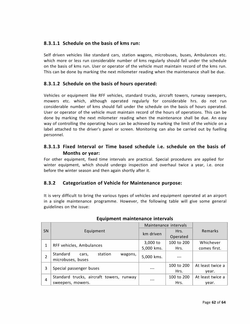
Page 62 of 64
SN EquipmentMaintenance intervals
Remarkskm driven Hrs.Operated
1 RFF vehicles, Ambulances 3,000 to5,000 kms.
100 to 200Hrs.
Whichevercomes first.
2 Standard cars, station wagons,microbuses, buses 5,000 kms. ‐‐‐
3 Special passenger buses ‐‐‐ 100 to 200Hrs.
At least twice ayear.
4 Standard trucks, aircraft towers, runwaysweepers, mowers. ‐‐‐ 100 to 200
Hrs.At least twice a
year.
8.3.1.1 Schedule on the basis of kms run:
Self driven vehicles like standard cars, station wagons, microbuses, buses, Ambulances etc.which more or less run considerable number of kms regularly should fall under the scheduleon the basis of kms run. User or operator of the vehicle must maintain record of the kms run.This can be done by marking the next milometer reading when the maintenance shall be due.
8.3.1.2 Schedule on the basis of hours operated:
Vehicles or equipment like RFF vehicles, standard trucks, aircraft towers, runway sweepers,mowers etc. which, although operated regularly for considerable hrs. do not runconsiderable number of kms should fall under the schedule on the basis of hours operated.User or operator of the vehicle must maintain record of the hours of operations. This can bedone by marking the next milometer reading when the maintenance shall be due. An easyway of controlling the operating hours can be achieved by marking the limit of the vehicle on alabel attached to the driver's panel or screen. Monitoring can also be carried out by fuellingpersonnel.
8.3.1.3 Fixed Interval or Time based schedule i.e. schedule on the basis ofMonths or year:
For other equipment, fixed time intervals are practical. Special procedures are applied forwinter equipment, which should undergo inspection and overhaul twice a year, i.e. oncebefore the winter season and then again shortly after it.
8.3.2 Categorization of Vehicle for Maintenance purpose:
It is very difficult to bring the various types of vehicles and equipment operated at an airportin a single maintenance programme. However, the following table will give some generalguidelines on the issue:
Equipment maintenance intervals
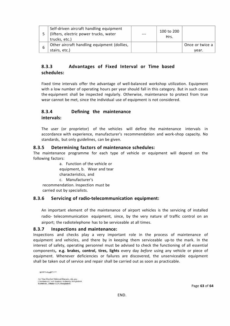
Page 63 of 64
5Self‐driven aircraft handling equipment(lifters, electric power trucks, watertrucks, etc.)
‐‐‐ 100 to 200Hrs.
6 Other aircraft handling equipment (dollies,stairs, etc.)
Once or twice ayear.
8.3.3 Advantages of Fixed Interval or Time basedschedules:
Fixed time intervals offer the advantage of well‐balanced workshop utilization. Equipmentwith a low number of operating hours per year should fall in this category. But in such casesthe equipment shall be inspected regularly. Otherwise, maintenance to protect from truewear cannot be met, since the individual use of equipment is not considered.
8.3.4 Defining the maintenanceintervals:
The user (or proprietor) of the vehicles will define the maintenance intervals inaccordance with experience, manufacturer's recommendation and work‐shop capacity. Nostandards, but only guidelines, can be given.
8.3.5 Determining factors of maintenance schedules:The maintenance programme for each type of vehicle or equipment will depend on thefollowing factors:
a. Function of the vehicle orequipment, b. Wear and tearcharacteristics, andc. Manufacturer's
recommendation. Inspection must becarried out by specialists.
8.3.6 Servicing of radio‐telecommunication equipment:
An important element of the maintenance of airport vehicles is the servicing of installedradio‐ telecommunication equipment, since, by the very nature of traffic control on anairport; the radiotelephone has to be serviceable at all times.
8.3.7 Inspections and maintenance:Inspections and checks play a very important role in the process of maintenance ofequipment and vehicles, and there by in keeping them serviceable up‐to the mark. In theinterest of safety, operating personnel must be advised to check the functioning of all essentialcomponents, e.g. brakes, control, tires, lights every day before using any vehicle or piece ofequipment. Whenever deficiencies or failures are discovered, the unserviceable equipmentshall be taken out of service and repair shall be carried out as soon as practicable.
END.

Page 64 of 64