Embed Size (px)
Citation preview
Copyright © A. Deepak Publishing. All rights reserved.
www.JoSSonline.comwww.DeepakPublishing.com
Abstract
At altitudes below 500 km, satellites experience a significant amount of aerodynamic drag that can be utilized to stabilize satellites to align with the relative wind direction. Designing a non-rotating spacecraft such that the center of pressure is behind the center of mass provides an aerodynamic restoring torque, which in combination with an oscillation damping system provides stability and alignment with the spacecraft velocity vector. Passive aerodynamic stability and damping has been demonstrated on orbit by the Soviet Union on Cosmos-149 and Cosmos-320 in 1967 and 1970, respectively, and by NASA on the Passive Aerodynamically Stabilized Magnet-ically-damped Satellite (PAMS) spacecraft, deployed from STS-77 in 1996. This paper presents our analysis of aerodynamic stability solutions for the CubeSat domain. CubeSat form factors are significantly smaller and lighter than the previous flight demonstrations; moreover, they must fit inside a CubeSat launcher, and only deploy aero-dynamic elements post orbit-insertion. We describe completely passive solutions for 3U and 1U CubeSats, where aerodynamic fins are deployed and magnetic hysteresis material is used for oscillation damping. We also show that greater velocity vector alignment can be achieved using active rate damping, using a magnetometer and magnetic torque coils running the B-dot control law to provide improved oscillation damping. Component selections are of-fered to create off-the-shelf aerodynamically stable CubeSat platforms, and we conclude that passive aerodynamic stability is suitable for the altitude and inclination of upcoming CubeSat flight opportunities on International Space Station (ISS) crew re-supply missions.
Aerodynamic Stability for CubeSats at ISS Orbit
Samir A. Rawashdeh and James E. Lumpp, Jr.Space Systems Laboratory, Electrical and Computer Engineering, University of Kentucky, Lexington, KY
1. Introduction
Passive attitude stabilization, in general, is an at-tractive attitude control solution for satellites when coarse pointing is required, especially if power, mass, and volume are constrained. Tuning and designing the
spacecraft to specific geometric, mass, and magnetic properties can provide passive attitude control, without the need for active sensors or actuators.
Magnetic, gravity gradient, and aerodynamic torques are the main sources of moments on Small Sat-ellites in Low Earth Orbit (LEO). Solar radiation pres-
Rawashdeh, S., et al. (2013): JoSS, Vol. 2, No. 1, pp. 85-104(Peer-reviewed Article available at www.jossonline.com)
JoSS, Vol. 2, No. 1, p. 85
Copyright © A. Deepak Publishing. All rights reserved.
sure is also an important factor for satellites with signif-icantly large surface areas. A satellite can be designed to amplify one of these forces to overcome the others to achieve stability. For example, several CubeSats em-ployed passive magnetic stabilization, where perma-nent magnets align the satellite with Earth’s magnetic field, to provide antenna or sensor pointing (Rawash-deh and Lumpp, 2010; Cutler et al., 2010). CubeSats have also been designed to deploy gravity booms to create a gravity gradient bias and achieve nadir point-ing (Waydo et al., 2002). In addition, aerodynamic torquing in low orbits can be used to achieve velocity-vector pointing, which is the focus of this paper.
Angular rate damping must accompany these stabi-lization techniques (Rawashdeh, 2009). While the en-vironmental torques would provide restoring torques necessary for stability, a form of angular rate damping is necessary to reach a steady-state condition. The use of active attitude control actuators, such as reaction wheels or magnetic torque coils, can help to achieve angular rate damping, at the cost of their added com-plexity. There are also simple passive solutions that re-quire no power and processing capabilities (and have fewer failure modes) such as the inclusion of magnetic hysteresis material (Rawashdeh, 2009; Levesque, 2003), particle dampers, and fluid dampers (Abel, 2011).
The Soviet Union and NASA have successfully demonstrated passive aerodynamic stability on orbit on larger than CubeSat-class satellites. In addition, aerodynamic stability with active damping has been demonstrated on a 3U CubeSat. The research described in this paper focused on the feasibility of completely passive solutions for 1U and 3U CubeSat designs that can be built with commercial off-the-shelf components. Active damping using magnetic torque coils is also considered, for improved steady-state performance.
Aerodynamic stability has been shown to be fea-sible for altitudes below 500 km. In conjunction with a passive damping solution, it provides a simple and low cost pointing solution. Velocity vector alignment is convenient for spacecraft dipole antenna pointing or when a sensor requires its aperture to track the veloc-ity vector, for example, for atmospheric plasma mea-surements or Earth horizon sensing. The design of
the CubeSats in this work feature deployable drag fins (resembling a shuttlecock) that provide their attitude aerodynamic stability. The increased drag area caused by the fins reduces its orbital lifetime to be on the order of months for ISS altitudes, which is desirable in many cases to mitigate orbital debris concerns.
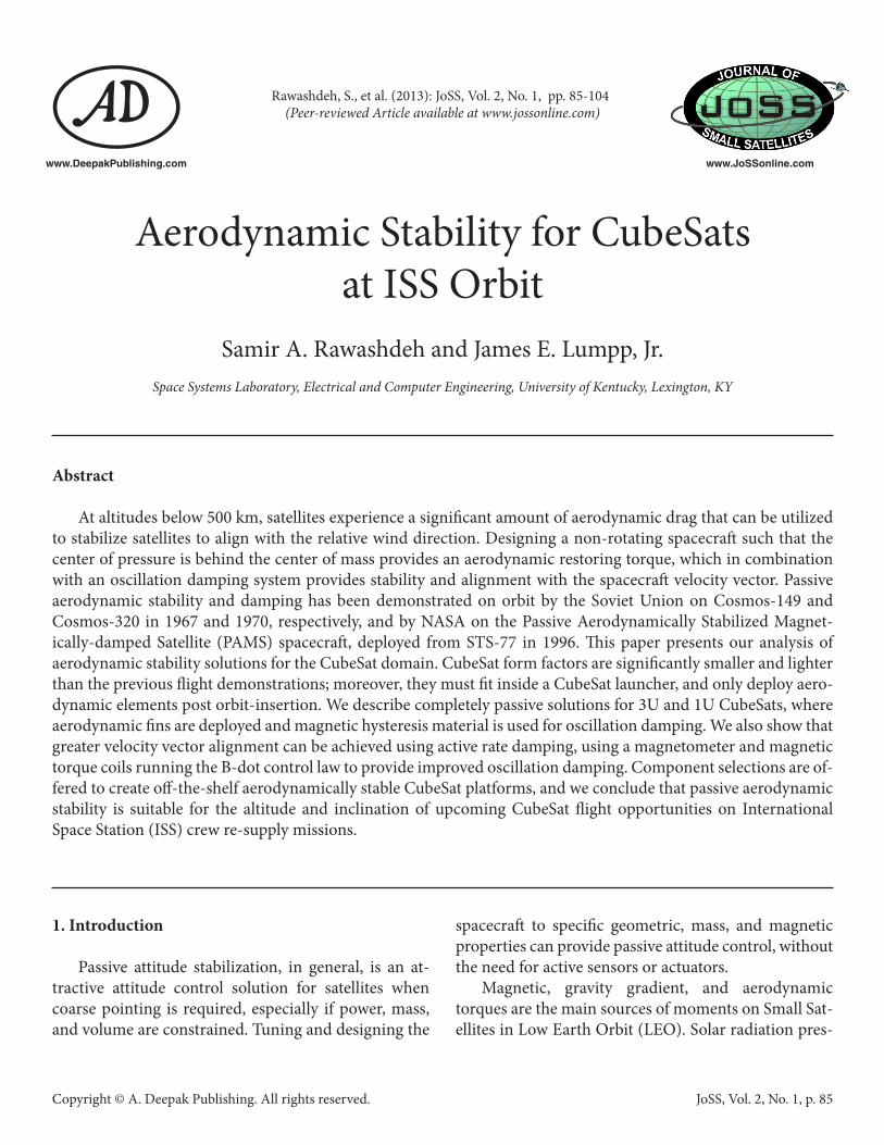
SpaceX reports that a significant number of Cube-Sat launch opportunities are expected to become avail-able on upcoming crew re-supply missions to the In-ternational Space Station (ISS), , each mission carrying up to four CubeSat deployers (Bjelde, 2011). From an attitude control point of view, satellites at this relatively low altitude are dominated by aerodynamic torques as shown in Table 1. This will drive complexity and limit the feasibility of common attitude control schemes that are not designed to counter disturbance torques of that magnitude. The designs presented in this paper utilize the strong aerodynamics for stability, and are proposed to be simple and low cost alternatives that are suitable for short-term and reoccurring experimental missions on ISS crew re-supply launches.
Table 1. Environmental Torques in General Regions of Influence (adapted to metric units from Schrello, 1961).
Regions of Influence
Altitude Range Environmental Effects
Region I Below 300 km Aerodynamic torques domi-nate angular motion
Region II 300-650 km Aerodynamic and Gravita-tional torques are comparable
Region III 650-1000 km Aerodynamic, Gravitational and Solar torques are compa-rable
Region IV Above 1000 km Solar and Gravitational torques dominate angular motions
This paper discusses aerodynamic stability solu-tions for the CubeSat domain and suggests alternatives that are capable of providing passive stabilization for
Rawashdeh, S., et al.
JoSS, Vol. 2, No. 1, p. 86

Copyright © A. Deepak Publishing. All rights reserved.
ISS altitude and inclination. The attitude propagator described herein is used to observe the satellite’s dy-namic response and steady-state behavior caused by aerodynamic torques, while also taking into account perturbing torques due to gravity gradient and mag-netic effects. Stability characteristics and pointing er-rors are shown for three spacecraft designs based on off-the-shelf components.
2. Background
At altitudes near the Kármán line (100 km), the Knudsen number typically begins to exceed 1, indicat-ing that the atmosphere more accurately corresponds to a rarefied, free-molecular flow regime than a con-tinuum flow regime (Wertz, 1978). Therefore, an ap-proach based on free-molecular aerodynamics or direct simulation of individual atmospheric particles on the satellite is necessary. Atmospheric drag for small satel-lites becomes a prominent source of disturbance and angular moments in the low part of LEO, at altitudes of 500 km and below. Atmospheric density decreases ex-ponentially as a function of altitude, and atmospheric drag effects become minimal at higher altitudes. Table 1 summarizes the relative magnitudes of aerodynamic, gravity gradient and solar torques as a function of al-titude. Note that the region boundaries in Table 1 are inexact, and are affected by the spacecraft design. For example, satellites with large cross-sectional areas will experience significant solar radiation torques at lower altitudes, and a symmetric satellite does not experience significant gravity gradient torques.
The earliest research on satellite rotational dynam-ics caused by the residual atmosphere, and the concept of utilizing these forces for stability, dates back to the late 1950s and early 1960s (Schrello, 1961; Wall, 1959). The selected references here include mathematical models and a number of proposed aerodynamically stable designs, and conclude that aerodynamic stabil-ity can be achieved at altitudes around 300 miles (483 km) and below, that several concepts show theoretical feasibility, and that oscillatory behavior is expected, ne-cessitating angular rate damping for stability.
The Soviet Union conducted the first on-orbit dem-
onstrations of aerodynamically stabilized satellites, in 1967 (Cosmos 149) and in 1970 (Cosmos 320) (Wade, 2012; Sarychev et al., 2007; Sarychev et al., 1984; Sary-chev and Ovchinnikov, 1994). The two spacecraft were known as “space arrows” because of their extended aerodynamic skirt stabilizers. Figure 1 is a photograph of a museum model of the space arrow. Damping was achieved with the use of two gyroscopes connected to the satellite body through viscous-spring restraints that dissipate energy when satellite oscillations cause gyro-scope precession. The satellite weighed 375 kg, was in orbit at 48.4° inclination, and operated in altitudes be-tween 246 and 326 km.
Figure 1. Cosmos 149 (K.E. Tsiolkovsky State Museum of The History of Cosmonautics, 2004-2012).
Aerostabilization in LEO was also flight tested as an experiment on the shuttle Endeavour in 1996 (NASA JSC, 1996). The Passive Aerodynamically Stabilized Magnetically-damped Satellite (PAMS) experiment demonstrated the feasibility of aerostabilization with magnetic hysteresis material for damping. The PAMS
Aerodynamic Stability for CubeSats at ISS Orbit
JoSS, Vol. 2, No. 1, p. 87
Copyright © A. Deepak Publishing. All rights reserved.
satellite had a cylindrical “stove pipe” design, with a significantly thicker shell on one end to shift the center of mass of the satellite and produce an aerodynamically stable design for altitudes from 250 to 325 km (Kumar, et al., 1996; Kumar et al., 1995; Pacini and Skillman, 1995).
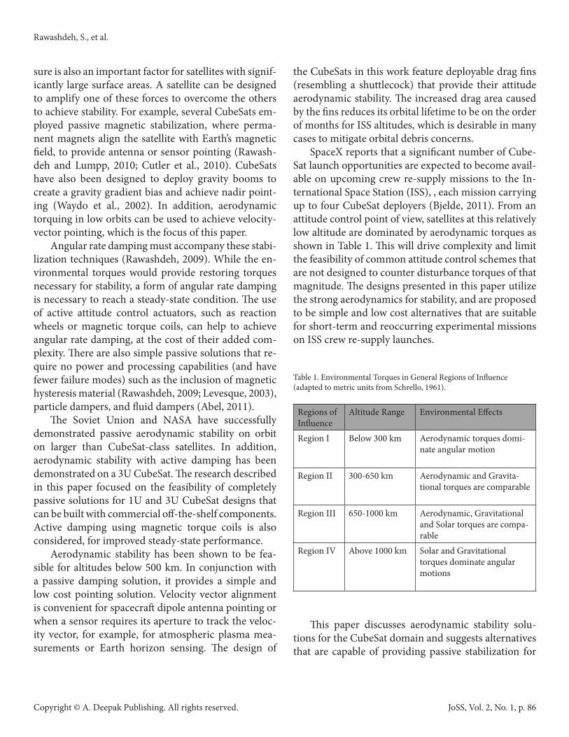
The NASA simulations for PAMS were based on free-molecular aerodynamics and incorporated varia-tions in atmospheric density, global winds, and solar radiation. They also simulated the behavior of hyster-esis material cycling in a model of the Earth’s magnetic field, and showed damping within 1 day, and a worst-case cone angle of 9°. The actual flight experiment was deemed a success after several rendezvous operations (NASA GSFC, 1996). Figure 2 shows PAMS with the shuttle Endeavour in view.
Figure 2. NASA photo of PAMS taken from Shuttle Endeavour (NASA GSFC, 1996).
3. Previous Work on CubeSats
The dimensions of PAMS are similar to those of CubeSats (see verification section); however, the Cube-Sat standard does not allow such an offset in the center of mass unless a shift is performed post-deployment. In the design studied here, a “shuttlecock” design is used as an effective way to shift the center of drag pressure behind the center of mass after orbit insertion while still conforming to the CubeSat standard that requires that the center of mass lies within 2 cm of the geomet-ric center (CalPoly, 2012).
Psiaki proposed a shuttlecock design to obtain aerodynamic stability on a 1U CubeSat (Psiaki, 2004). The system uses four deployable “feathers” that re-semble retractable tape measures extending from a 1U CubeSat body. It also incorporates active magnetic torque coils for damping, and was shown through sim-ulation to achieve stability for all altitudes below 500 km. The design was evaluated by comparing a simpli-fied stiffness model with a model based on free-molec-ular aerodynamics. The narrow one-meter-long feath-ers were deployed at 12°. The design was shown to stop tumbling within one hour, and achieved a steady-state pointing error of 2° within 15 hours.
In previous work at the University of Kentucky Space Systems Laboratory, the authors investigated the conditions of stability of a 3U CubeSat with deploy-able side panels. We completed a one-degree-of-free-dom analysis on the effect of varying panel lengths and deployment angles for the 3U form factor at varying altitudes in the presence of gravity gradient moments (Rawashdeh et al., 2009). In other research, a six- de-gree-of-freedom orbit and attitude propagator was de-veloped with models for aerodynamic, gravity gradient, permanent magnet, and magnetic hysteresis material torques (Rawashdeh, 2009). The attitude propagator was mainly used to support KySat-1, a 1U CubeSat manifested on NASA’s ElaNa-1 mission, in designing satellites with permanent magnet attitude stability sys-tems with hysteresis material for angular rate damping. The propagator, called Smart Nanosatellite Attitude Propagator (SNAP), was verified by simulating sever-al spacecraft of known designs, including PAMS, and comparing the simulations with their on-orbit results (Rawashdeh and Lumpp, 2010). In our study, we im-proved on the aerodynamic modeling by increasing the fidelity of the geometric representation, as well as im-proving the magnetic hysteresis model to be a continu-ous and smooth mathematical model, and introducing a model for active magnetic control. Then we leverage the SNAP simulation tool and previous studies on gen-eral stability across altitudes and propose aerodynami-cally stable CubeSat designs for the ISS altitude using commercially available components, and use the prop-agator to simulate the satellites’ attitude response in all degrees of freedom.
Rawashdeh, S., et al.
JoSS, Vol. 2, No. 1, p. 88
Copyright © A. Deepak Publishing. All rights reserved.
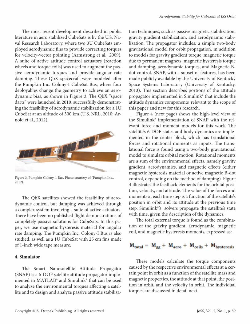
The most recent development described in public literature in aero stabilized CubeSats is by the U.S. Na-val Research Laboratory, where two 3U CubeSats em-ployed aerodynamic fins to provide correcting torques for velocity-vector pointing (Armstrong et al., 2009). A suite of active attitude control actuators (reaction wheels and torque coils) was used to augment the pas-sive aerodynamic torques and provide angular rate damping. These QbX spacecraft were modeled after the Pumpkin Inc. Colony-I CubeSat Bus, where four deployables change the geometry to achieve an aero-dynamic bias, as shown in Figure 3. The QbX “space darts” were launched in 2010, successfully demonstrat-ing the feasibility of aerodynamic stabilization for a 1U CubeSat at an altitude of 300 km (U.S. NRL, 2010; Ar-nold et al., 2012).
Figure 3. Pumpkin Colony-1 Bus. Photo courtesy of (Pumpkin Inc., 2012).
The QbX satellites showed the feasibility of aero-dynamic control, but damping was achieved through a complex system involving a suite of active actuators. There have been no published flight demonstrations of completely passive solutions for CubeSats. In this pa-per, we use magnetic hysteresis material for angular rate damping. The Pumpkin Inc. Colony-I Bus is also studied, as well as a 1U CubeSat with 25 cm fins made of 1-inch wide tape measure.
4. Simulator
The Smart Nanosatellite Attitude Propagator (SNAP) is a 6-DOF satellite attitude propagator imple-mented in MATLAB® and Simulink® that can be used to analyze the environmental torques affecting a satel-lite and to design and analyze passive attitude stabiliza-
tion techniques, such as passive magnetic stabilization, gravity gradient stabilization, and aerodynamic stabi-lization. The propagator includes: a simple two-body gravitational model for orbit propagation, in addition to models for gravity gradient torque, magnetic torque due to permanent magnets, magnetic hysteresis torque and damping, aerodynamic torques, and Magnetic B-dot control. SNAP, with a subset of features, has been made publicly available by the University of Kentucky Space Systems Laboratory (University of Kentucky, 2013). This section describes portions of the attitude propagator implemented in Simulink® that include the attitude dynamics components relevant to the scope of this paper and new for this research.
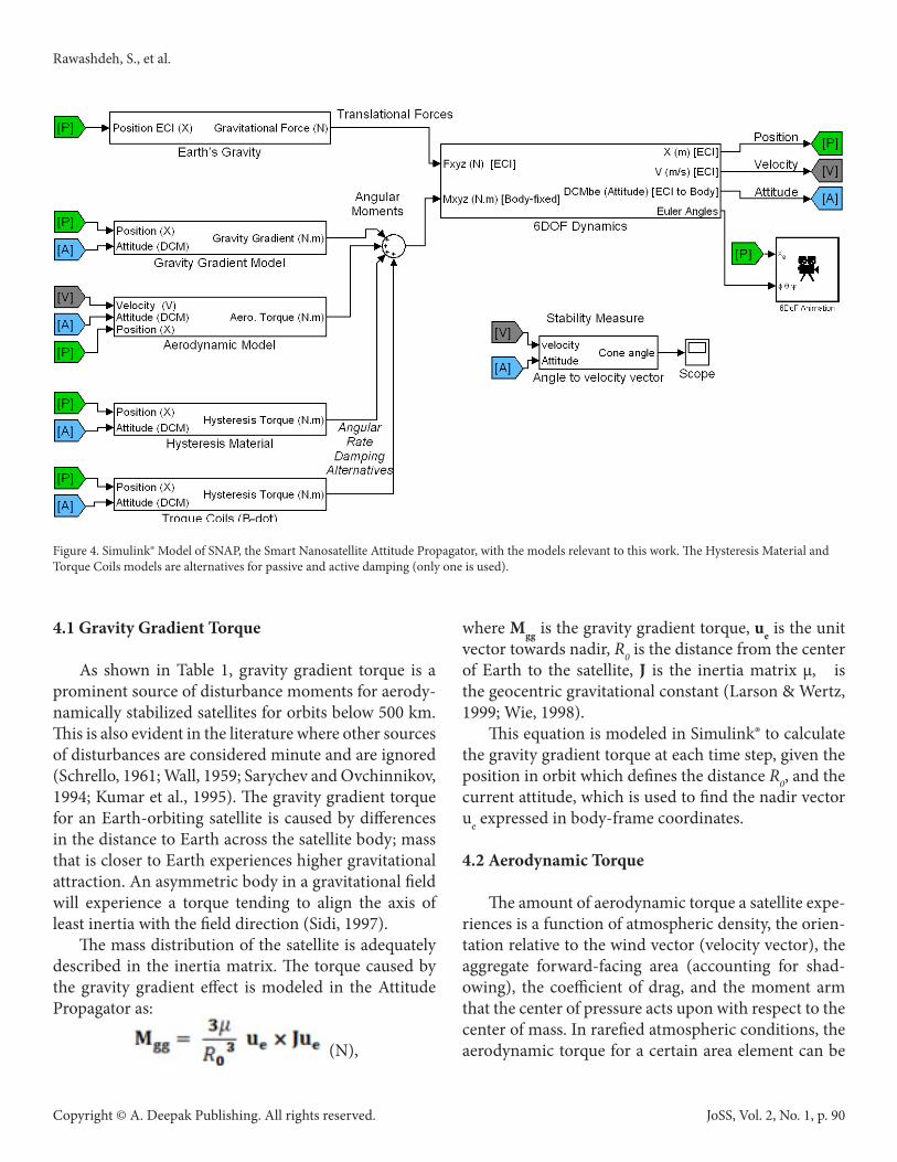
Figure 4 (next page) shows the high-level view of the Simulink® implementation of SNAP with the rel-evant force and moment models for this work. The satellite’s 6-DOF states and body dynamics are imple-mented in the center block, which has translational forces and rotational moments as inputs. The trans-lational force is found using a two-body gravitational model to simulate orbital motion. Rotational moments are a sum of the environmental effects, namely gravity gradient, aerodynamics, and magnetic effects (either magnetic hysteresis material or active magnetic B-dot control, depending on the method of damping). Figure 4 illustrates the feedback elements for the orbital posi-tion, velocity, and attitude. The value of the forces and moments at each time step is a function of the satellite’s position in orbit and its attitude at the previous time step. Simulink®’s solvers propagate the satellite’s state with time, given the description of the dynamics.
The total external torque is found as the combina-tion of the gravity gradient, aerodynamic, magnetic coil, and magnetic hysteresis moments, expressed as:
These models calculate the torque components caused by the respective environmental effects at a cer-tain point in orbit as a function of the satellite mass and magnetic properties, the attitude at that point, the posi-tion in orbit, and the velocity in orbit. The individual torques are discussed in detail next.
Aerodynamic Stability for CubeSats at ISS Orbit
JoSS, Vol. 2, No. 1, p. 89
Copyright © A. Deepak Publishing. All rights reserved.
4.1 Gravity Gradient Torque
As shown in Table 1, gravity gradient torque is a prominent source of disturbance moments for aerody-namically stabilized satellites for orbits below 500 km. This is also evident in the literature where other sources of disturbances are considered minute and are ignored (Schrello, 1961; Wall, 1959; Sarychev and Ovchinnikov, 1994; Kumar et al., 1995). The gravity gradient torque for an Earth-orbiting satellite is caused by differences in the distance to Earth across the satellite body; mass that is closer to Earth experiences higher gravitational attraction. An asymmetric body in a gravitational field will experience a torque tending to align the axis of least inertia with the field direction (Sidi, 1997).
The mass distribution of the satellite is adequately described in the inertia matrix. The torque caused by the gravity gradient effect is modeled in the Attitude Propagator as:
(N),
where Mgg is the gravity gradient torque, ue is the unit vector towards nadir, R0 is the distance from the center of Earth to the satellite, J is the inertia matrix μ, is the geocentric gravitational constant (Larson & Wertz, 1999; Wie, 1998).
This equation is modeled in Simulink® to calculate the gravity gradient torque at each time step, given the position in orbit which defines the distance R0, and the current attitude, which is used to find the nadir vector ue expressed in body-frame coordinates.
4.2 Aerodynamic Torque
The amount of aerodynamic torque a satellite expe-riences is a function of atmospheric density, the orien-tation relative to the wind vector (velocity vector), the aggregate forward-facing area (accounting for shad-owing), the coefficient of drag, and the moment arm that the center of pressure acts upon with respect to the center of mass. In rarefied atmospheric conditions, the aerodynamic torque for a certain area element can be
Figure 4. Simulink® Model of SNAP, the Smart Nanosatellite Attitude Propagator, with the models relevant to this work. The Hysteresis Material and Torque Coils models are alternatives for passive and active damping (only one is used).
Rawashdeh, S., et al.
JoSS, Vol. 2, No. 1, p. 90
Copyright © A. Deepak Publishing. All rights reserved.
calculated by:
(N),
where Maero is the aerodynamic torque, uv is the unit velocity vector, scp is the vector from the center of pres-sure to the center of mass, ρ is the atmospheric den-sity, V is the satellite velocity, Cd is the drag coefficient (set to equal 2 in this work), and A is the affected area (Wertz, 1978; Larson & Wertz, 1999).
The aerodynamic torque for a certain attitude is a function of the area facing the velocity vector that is not shadowed by any other parts of the spacecraft body. Taking the torque that is due to aerodynamics into ac-count requires a method of representing the spacecraft geometry. Then, an algorithm is needed to calculate the torque the spacecraft experiences given the geometric representation and the attitude of the satellite relative to the wind vector (negative velocity vector).
The geometry of the satellite is discretized into vol-umetric elements, as shown in Figure 9 in the analy-sis section, at a dot per 0.125 cm3. A look-up table is generated that maps the attitude relative to the veloc-ity vector to a torque factor that is later scaled by the atmospheric density and orbital velocity to find the aerodynamic torque the satellite experiences at that orientation. This torque profile is generated before the simulation runtime to reduce the number of computa-tions and minimize the simulation duration. At run-time, the satellite’s angle to the velocity vector (the in-coming wind) is computed from the current attitude and orbit model. The look-up table returns the torque factor associated with that deflection angle. The map-ping table is generated across a full range of satellite rotations, by considering elements directly facing the wind vector that are not shadowed by other satellite components. A form of numerical integration is per-formed by summing up the torque contributions of all the satellite elements to find the total torque affecting the satellite at a given attitude. Although shadowing is often ignored in literature when the main body of the satellite is small relative to the dimensions of the fins, this assumption cannot be made for the designs that will follow, where shadowing is an important factor to
consider for CubeSat solutions. This geometric repre-sentation is a very convenient tool for solving this type of problem.
The look-up table is used at runtime to obtain a torque factor, described by
given the current satellite attitude. That value is then scaled by the atmospheric density (ρ) at that altitude using another look-up table, and the square of the sat-ellite’s orbital velocity ( ) computed from the orbit propagator to find the final torque affecting the satellite at that time step.
4.3 Magnetic Torque Coils
Next, we develop the model for magnetic torque coils, which are used here as an alternative to provide angular rate damping for improved tracking accuracy. A magnetic dipole in a magnetic field experiences an angular moment that aligns the dipole with the mag-netic field lines, like a compass needle pointing north. The torque affecting a satellite due to a magnetic dipole interacting with the Earth’s magnetic field is modeled as:
(N),
where Mcoils is the magnetic torque vector in body-frame, m is the magnetic dipole moment vector in Am2 in body-frame, BEarth is the Earth magnetic flux density vector in body-frame (Sidi, 1997).
In this paper, the magnetic dipole moment m is generated using magnetic torque coils based on the popular B-dot control law:
(Am2),
where m is the magnetic dipole moment vector, K is a tunable gain factor, and B is the Earth magnetic flux density vector in body frame (Silani & Lovera, 2002). The B-dot control law actuates the torque coils to coun-ter any changes in the observed magnetic field. From the satellite perspective, variations in the magnetic
Aerodynamic Stability for CubeSats at ISS Orbit
JoSS, Vol. 2, No. 1, p. 91
Copyright © A. Deepak Publishing. All rights reserved.
field caused by the satellite travel through orbit and the Earth’s rotation are slower than the observed magnetic field variations caused by the satellites angular motion; therefore, the change in the observed magnetic field approximates the satellite angular rates. In effect, the B-dot control law acts to resist angular motion, and is an effective detumbling and damping solution.
The Earth’s magnetic field is modeled as a dipole (L-Shell Model) (Wertz, 1978). Given the position in orbit at a given simulation step, the local magnetic field from the Earth can be found using the dipole model, and rotated to body-frame coordinates, given the atti-tude of the satellite. At runtime, given the Earth’s mag-netic field, and the satellite’s orientation, the magnetic torque due to the magnetic dipole is found.
The active magnetic damping solution requires a set of magnetic torque coils, typically three that are in-stalled orthogonally. It also requires knowledge of the magnetic field, which can be measured using a mag-netometer. In this paper, active damping is only pre-sented as a proof of concept and perfect knowledge of the magnetic field is assumed. An upper limit for the magnetic dipole per coil of 0.04 Am2 is set, as a con-servative number that can be achieved with air-core coils embedded in solar boards as traces across mul-tiple layers. Solar boards with embedded torque coils and magnetometers are commercially available (GOM Space, 2012).
4.4 Magnetic Hysteresis Damping
While magnetic hysteresis material is a completely passive solution for angular rate damping, it is non-trivial to study and predict, and motivated the imple-mentation of a simulation environment. Magnetically “soft” material of low coercivity can be magnetized by the Earth’s magnetic field and follows hysteresis patterns as it cycles in a magnetic field. This makes it suitable as a means for angular rate damping for small-satellites in orbits with a significant magnetic field. Magnetic hysteresis is a physical property of ferromag-netic material. The material becomes magnetized when an external magnetic field is applied, forcing the mag-netic domains on the atomic level to polarize. Depend-ing on the magnetic remanence (Br) of the material, it
will retain a magnetic dipole of some strength when the external magnetic field is removed. The magnetic coercivity (Hc) of the material is the intensity of the ex-ternal magnetic field required to diminish the magne-tization from saturation to zero when applied against the polarity of the material. The lag (or “hysteresis”) in tracking the externally applied magnetic field caused by the coercivity and remanence of the material results in energy lost as heat in the material. The phenomenon can be thought of as the magnetic dipoles having “fric-tion” when their orientation is forced to change.
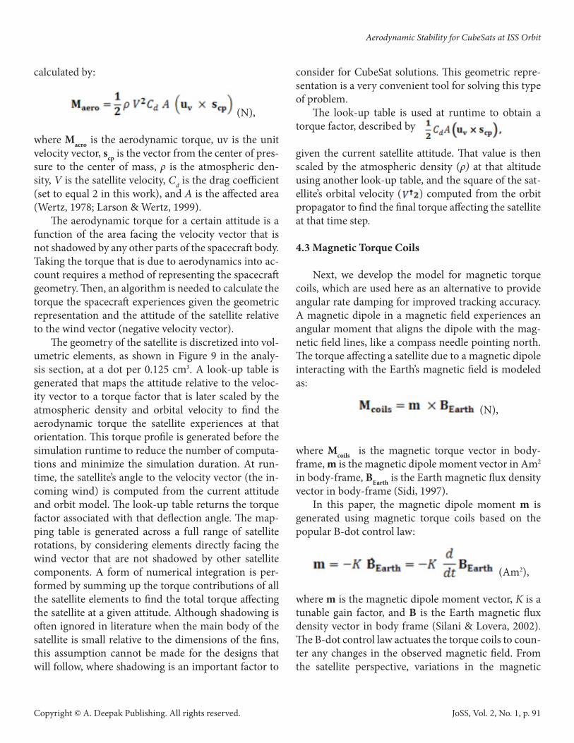
Figure 5 shows a sample magnetization curve gen-erated using the mathematical model of the hysteresis material used in this study (Flatley & Henretty, 1995). The mathematical recipe was developed to simulate the NASA PAMS satellite, and is a set of first order differen-tial relationships that we implemented and introduced to the propagator for this work. The model is an im-provement on previous parallelogram approximations (Rawashdeh, 2009) as the continuous non-switching nature of the curve adds fidelity to the simulations.
Figure 5. Trace of the hysteresis loop model of HyMu80.
Quantifying the amount of hysteresis material to include in a satellite design is challenging. The amount of damping caused by hysteresis material is not a fixed or calculated amount; it is a result of the behavior of the hysteresis material interacting and cycling through the
Rawashdeh, S., et al.
JoSS, Vol. 2, No. 1, p. 92
Copyright © A. Deepak Publishing. All rights reserved.
Earth’s magnetic field. Modeling and simulation are a convenient and effective way to study hysteresis mate-rial (Levesque, 2003).
Several inexpensive alternatives are available com-mercially, most commonly as electric shielding mate-rial. For example, HyMu80, Carpenter 49, Permalloy 80, and Mumetal are high-permeability alloys that are suitable as magnetic hysteresis material for spacecraft rotation damping. HyMu80, which is selected for the proposed designs in this paper, has a coercivity of 1.59 Am-1, remanence of 0.35 Tesla, and saturation of 0.73 Tesla.
5. NASA PAMS - Simulator Verification
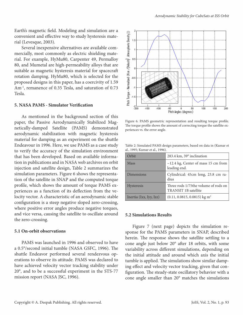
As mentioned in the background section of this paper, the Passive Aerodynamically Stabilized Mag-netically-damped Satellite (PAMS) demonstrated aerodynamic stabilization with magnetic hysteresis material for damping as an experiment on the shuttle Endeavour in 1996. Here, we use PAMS as a case study to verify the accuracy of the simulation environment that has been developed. Based on available informa-tion in publications and in NASA web archives on orbit injection and satellite design, Table 2 summarizes the simulation parameters. Figure 6 shows the representa-tion of the satellite in SNAP and the computed torque profile, which shows the amount of torque PAMS ex-periences as a function of its deflection from the ve-locity vector. A characteristic of an aerodynamic stable configuration is a steep negative sloped zero-crossing, where positive error angles produce negative torques, and vice versa, causing the satellite to oscillate around the zero-crossing.
5.1 On-orbit observations
PAMS was launched in 1996 and observed to have a 0.5°/second initial tumble (NASA GSFC, 1996). The shuttle Endeavor performed several rendezvous op-erations to observe its attitude. PAMS was declared to have achieved velocity vector tracking stability under 20°, and to be a successful experiment in the STS-77 mission report (NASA JSC, 1996).
Figure 6. PAMS geometric representation and resulting torque profile. The torque profile shows the amount of correcting torque the satellite ex-periences vs. the error angle.
Table 2: Simulated PAMS design parameters, based on data in (Kumar et al., 1995; Kumar et al., 1996).
Orbit 283.4 km, 39° inclination
Mass ~12.4 kg, Center of mass 15 cm from leading end.
Dimensions Cylindrical: 45cm long, 23.8 cm ra-dius
Hysteresis Three rods 1/75the volume of rods on TRANSIT 1B satellite
Inertia (Ixx, Iyy, Izz) (0.11, 0.0815, 0.0815) kg m2
5.2 Simulations Results
Figure 7 (next page) depicts the simulation re-sponse for the PAMS parameters in SNAP, described herein. The response shows the satellite settling to a cone angle just below 20° after 18 orbits, with some variability across different simulations, depending on the initial attitude and around which axis the initial tumble is applied. The simulations show similar damp-ing effect and velocity vector tracking, given that con-figuration. The steady-state oscillatory behavior with a cone angle smaller than 20° matches the simulations
Aerodynamic Stability for CubeSats at ISS Orbit
JoSS, Vol. 2, No. 1, p. 93
Copyright © A. Deepak Publishing. All rights reserved.
and observations performed by NASA (NASA GSFC, 1996).
Figure 7. PAMS simulated attitude response. The plot shows the cone angle relative to the velocity vector.
6. Aerostabilized CubeSat Design As discussed earlier, aerodynamic stability has
been demonstrated with passive damping on the Cos-mos Space Arrows and NASA PAMS, and proposed and demonstrated on CubeSats with active damping. An attitude propagator was developed, to study the fea-sibility of completely passive solutions while conform-ing to the CubeSat form factor.
Aerostabilized CubeSats are required to conform to the CubeSat mass limit (1.33 kg per 1U CubeSat) and the center of mass restriction, where the center of mass is required to be within two centimeters from the geo-metric center before deployment (CalPoly, 2012). This excludes the PAMS and Cosmos solutions, where the satellite is designed with a center of mass shift to create the aerodynamic bias, and any CubeSat solution would require that the separation between the center of pres-sure and center of mass be achieved after orbit inser-tion. The objective of the attitude solutions presented in this paper is to recover from the initial tumble after launch and then achieve and maintain velocity vector alignment in steady-state condition.
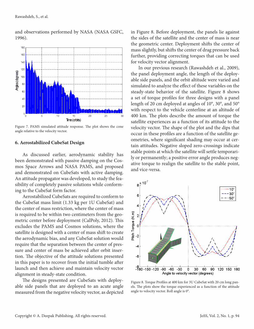
The designs presented are CubeSats with deploy-able side panels that are deployed to an acute angle measured from the negative velocity vector, as depicted
in Figure 8. Before deployment, the panels lie against the sides of the satellite and the center of mass is near the geometric center. Deployment shifts the center of mass slightly, but shifts the center of drag pressure back further, providing correcting torques that can be used for velocity vector alignment.
In our previous research (Rawashdeh et al., 2009), the panel deployment angle, the length of the deploy-able side panels, and the orbit altitude were varied and simulated to analyze the effect of these variables on the steady-state behavior of the satellite. Figure 8 shows a set of torque profiles for three designs with a panel length of 20 cm deployed at angles of 10°, 30°, and 50° with respect to the vehicle centerline at an altitude of 400 km. The plots describe the amount of torque the satellite experiences as a function of its attitude to the velocity vector. The shape of the plot and the dips that occur in these profiles are a function of the satellite ge-ometries, where significant shading may occur at cer-tain attitudes. Negative sloped zero-crossings indicate stable points at which the satellite will settle temporari-ly or permanently; a positive error angle produces neg-ative torque to realign the satellite to the stable point, and vice-versa.
Figure 8. Torque Profiles at 400 km for 3U CubeSat with 20 cm long pan-els. The plots show the torque experienced as a function of the attitude angle to velocity vector. Roll angle is 0°.
Rawashdeh, S., et al.
JoSS, Vol. 2, No. 1, p. 94
Copyright © A. Deepak Publishing. All rights reserved.
An exhaustive search through the panel deploy-ment angle, panel length, and orbit altitude was per-formed, to determine the optimal deployment angle and panel length. In general the panel length was found to mainly scale the torque profile in amplitude for pan-el lengths greater than 10 cm. Likewise, evaluating the torque profiles at lower altitudes with higher atmo-spheric density increases the torque experienced, and is manifested as a scaling in the torque profile. The main performance parameter considered was the amount of stiffness through the ram-facing angle. Stiffness is de-fined as the amount of correcting torque the satellite experiences for every 1° of error, which is calculated as the negative of the derivative of the pitch torque pro-file evaluated at the zero degree angle. Greater stiffness promises smaller steady-state errors and higher oscil-lation frequencies.
The torque profiles in Figure 8 provide considerable insight into how a geometric design would perform. It is evident that a deployment angle of 50° is most stiff through the zero crossing. It was found that angles be-yond 50° begin to provide diminishing return in terms of stiffness. Another important factor to consider in the design is the amount of forward-facing area that directly affects the orbit lifetime.
7. 3U CubeSat with Deployable Side Panels
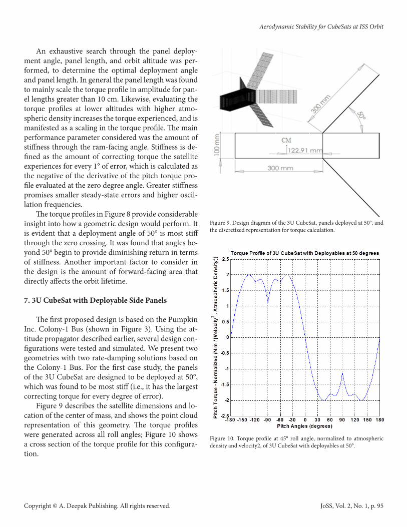
The first proposed design is based on the Pumpkin Inc. Colony-1 Bus (shown in Figure 3). Using the at-titude propagator described earlier, several design con-figurations were tested and simulated. We present two geometries with two rate-damping solutions based on the Colony-1 Bus. For the first case study, the panels of the 3U CubeSat are designed to be deployed at 50°, which was found to be most stiff (i.e., it has the largest correcting torque for every degree of error).
Figure 9 describes the satellite dimensions and lo-cation of the center of mass, and shows the point cloud representation of this geometry. The torque profiles were generated across all roll angles; Figure 10 shows a cross section of the torque profile for this configura-tion.
Figure 9. Design diagram of the 3U CubeSat, panels deployed at 50°, and the discretized representation for torque calculation.
Figure 10. Torque profile at 45° roll angle, normalized to atmospheric density and velocity2, of 3U CubeSat with deployables at 50°.
Aerodynamic Stability for CubeSats at ISS Orbit
JoSS, Vol. 2, No. 1, p. 95
Copyright © A. Deepak Publishing. All rights reserved.
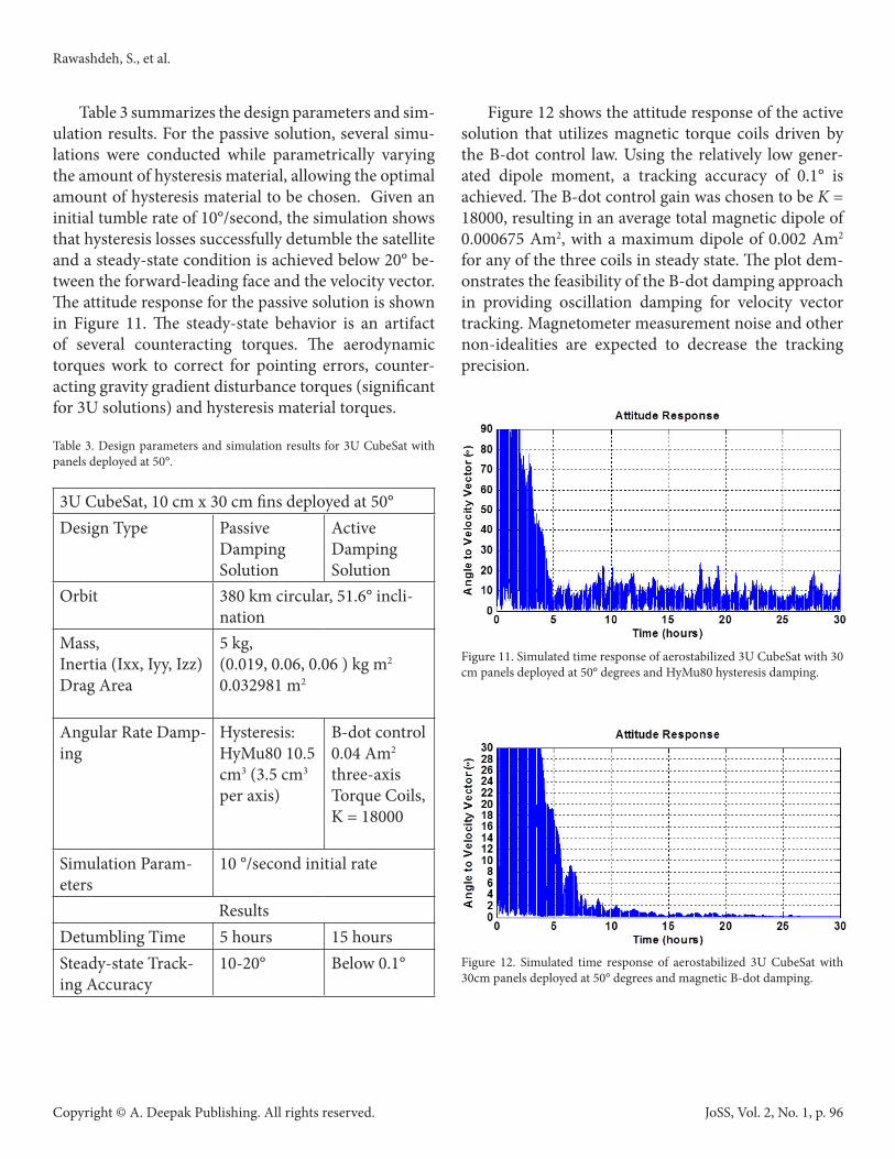
Table 3 summarizes the design parameters and sim-ulation results. For the passive solution, several simu-lations were conducted while parametrically varying the amount of hysteresis material, allowing the optimal amount of hysteresis material to be chosen. Given an initial tumble rate of 10°/second, the simulation shows that hysteresis losses successfully detumble the satellite and a steady-state condition is achieved below 20° be-tween the forward-leading face and the velocity vector. The attitude response for the passive solution is shown in Figure 11. The steady-state behavior is an artifact of several counteracting torques. The aerodynamic torques work to correct for pointing errors, counter-acting gravity gradient disturbance torques (significant for 3U solutions) and hysteresis material torques.
Table 3. Design parameters and simulation results for 3U CubeSat with panels deployed at 50°.
3U CubeSat, 10 cm x 30 cm fins deployed at 50°Design Type Passive
Damping Solution
Active Damping Solution
Orbit 380 km circular, 51.6° incli-nation
Mass,Inertia (Ixx, Iyy, Izz)Drag Area
5 kg,(0.019, 0.06, 0.06 ) kg m2
0.032981 m2
Angular Rate Damp-ing
Hysteresis: HyMu80 10.5 cm3 (3.5 cm3 per axis)
B-dot control 0.04 Am2 three-axis Torque Coils, K = 18000
Simulation Param-eters
10 °/second initial rate
ResultsDetumbling Time 5 hours 15 hoursSteady-state Track-ing Accuracy
10-20° Below 0.1°
Figure 12 shows the attitude response of the active solution that utilizes magnetic torque coils driven by the B-dot control law. Using the relatively low gener-ated dipole moment, a tracking accuracy of 0.1° is achieved. The B-dot control gain was chosen to be K = 18000, resulting in an average total magnetic dipole of 0.000675 Am2, with a maximum dipole of 0.002 Am2
for any of the three coils in steady state. The plot dem-onstrates the feasibility of the B-dot damping approach in providing oscillation damping for velocity vector tracking. Magnetometer measurement noise and other non-idealities are expected to decrease the tracking precision.
Figure 11. Simulated time response of aerostabilized 3U CubeSat with 30 cm panels deployed at 50° degrees and HyMu80 hysteresis damping.
Figure 12. Simulated time response of aerostabilized 3U CubeSat with 30cm panels deployed at 50° degrees and magnetic B-dot damping.
Rawashdeh, S., et al.
JoSS, Vol. 2, No. 1, p. 96
Copyright © A. Deepak Publishing. All rights reserved.
8. 3U CubeSat with Lower Drag
A deployment angle of 50° was found to be most stiff, promising the greatest pointing accuracy. As Fig-ures 11 and 12 show, coarse pointing can be achieved using hysteresis material, and fine pointing can be achieved using active magnetic damping. We note that a deployment angle of 50° results in a forward facing area of 0.033 m2, as noted in Table 3.
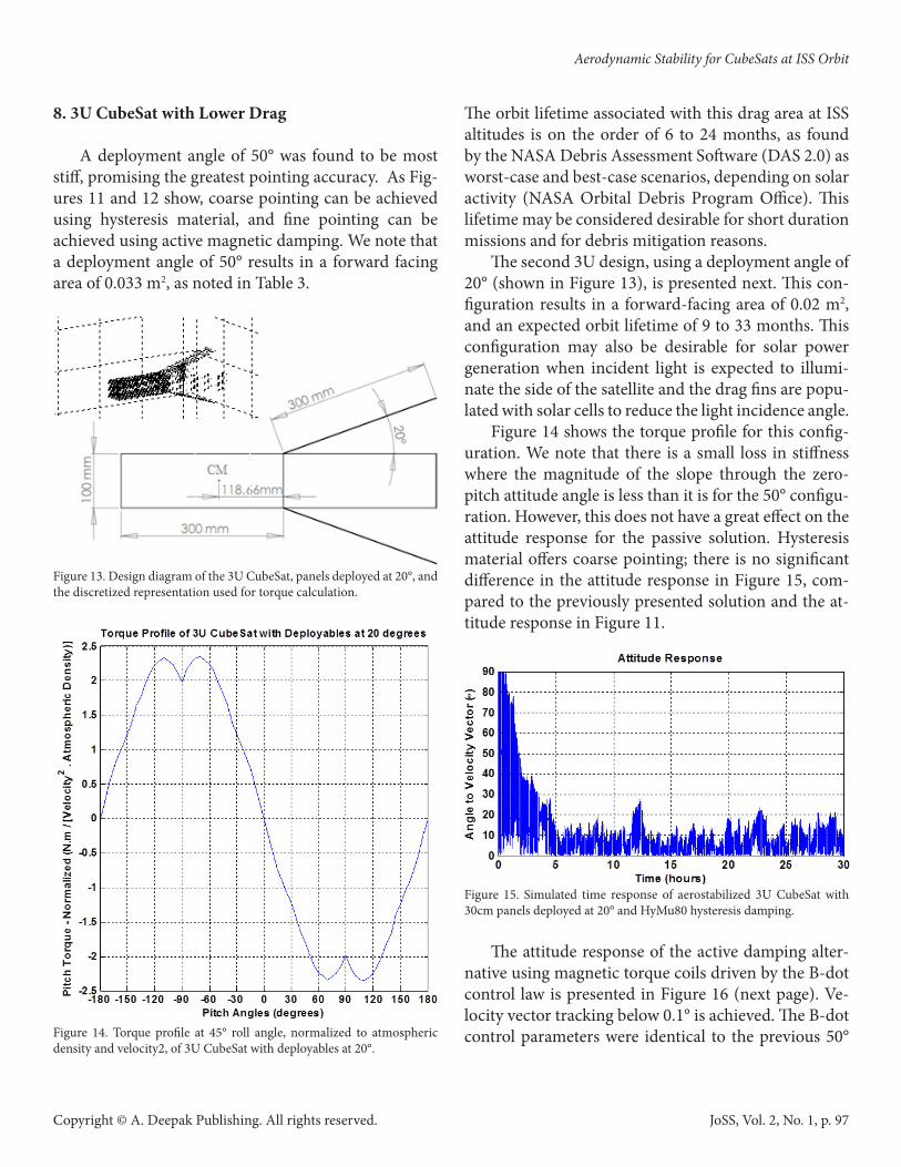
Figure 13. Design diagram of the 3U CubeSat, panels deployed at 20°, and the discretized representation used for torque calculation.
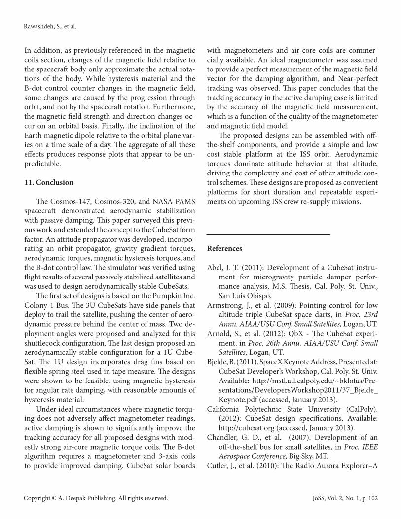
Figure 14. Torque profile at 45° roll angle, normalized to atmospheric density and velocity2, of 3U CubeSat with deployables at 20°.
The orbit lifetime associated with this drag area at ISS altitudes is on the order of 6 to 24 months, as found by the NASA Debris Assessment Software (DAS 2.0) as worst-case and best-case scenarios, depending on solar activity (NASA Orbital Debris Program Office). This lifetime may be considered desirable for short duration missions and for debris mitigation reasons.
The second 3U design, using a deployment angle of 20° (shown in Figure 13), is presented next. This con-figuration results in a forward-facing area of 0.02 m2, and an expected orbit lifetime of 9 to 33 months. This configuration may also be desirable for solar power generation when incident light is expected to illumi-nate the side of the satellite and the drag fins are popu-lated with solar cells to reduce the light incidence angle.
Figure 14 shows the torque profile for this config-uration. We note that there is a small loss in stiffness where the magnitude of the slope through the zero-pitch attitude angle is less than it is for the 50° configu-ration. However, this does not have a great effect on the attitude response for the passive solution. Hysteresis material offers coarse pointing; there is no significant difference in the attitude response in Figure 15, com-pared to the previously presented solution and the at-titude response in Figure 11.
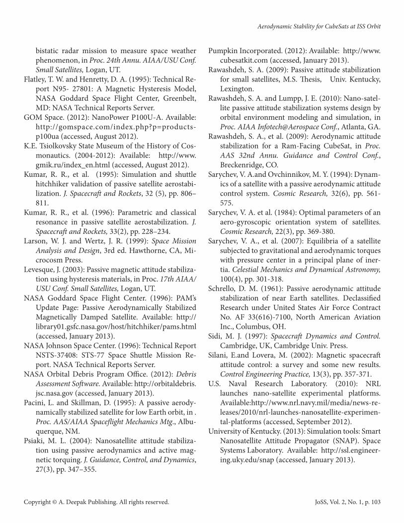
Figure 15. Simulated time response of aerostabilized 3U CubeSat with 30cm panels deployed at 20° and HyMu80 hysteresis damping.
The attitude response of the active damping alter-native using magnetic torque coils driven by the B-dot control law is presented in Figure 16 (next page). Ve-locity vector tracking below 0.1° is achieved. The B-dot control parameters were identical to the previous 50°
Aerodynamic Stability for CubeSats at ISS Orbit
JoSS, Vol. 2, No. 1, p. 97

Copyright © A. Deepak Publishing. All rights reserved.
deployment angle design. Table 4 summarizes the sim-ulation parameters and results for the 3U solution with side panels deployed at 20°.
Table 4. Design parameters and simulation results for 3U CubeSat with panels deployed at 20°.
3U CubeSat, 10 cm x 30 cm fins deployed at 20°Design Type Passive
Damping Solution
Active Damping Solution
Orbit 380 km circular, 51.6° incli-nation
Mass,Inertia (Ixx, Iyy, Izz)Drag Area
5 kg,(0.0109, 0.0664, 0.0664) kg m2
0.020261 m2
Angular Rate Damp-ing
Hysteresis: HyMu80 10.5 cm3 (3.5 cm3 per axis)
B-dot control 0.04 Am2 three-axis Torque Coils, K = 18000
Simulation Param-eters
10 °/second initial rate
ResultsDetumbling Time 5 hours 20 hoursSteady-state Track-ing Accuracy
15-20° Below 0.1°
Figure 16. Simulated time response of aerostabilized 3U CubeSat with 30cm panels deployed at 20° and magnetic B-dot damping.
9. 1U CubeSat with Tape-Measure Fins Next, we investigated the feasibility for a 1U Cube-
Sat solution. The 1U CubeSat is the most frequent form factor and usually has the lowest launch cost. We pres-ent an aerodynamically stable design that is feasibly un-der the weight and volume limitations of the 1U form factor. The main design requirements were simplicity and manufacturability, especially since at this time no off-the-shelf frame can be bought to readily achieve aerodynamic stability on a 1U CubeSat. Dimensions and deployment of the drag fins were considered, as well as the volume required for hysteresis material and the placement of the magnetic coils, in the case of the active damping solution.
Figure 17 shows the 1U CubeSat design that em-ploys drag fins that measure four 25 cm long and 2.5 cm wide. The fins, which can be constructed with us-ing 1-inch wide flexible tape measure spring steel, can be wrapped around the satellite and tied down before deployment, similar to the antenna deployment mech-anism on KySat-1 (Chandler, et al., 2007). Once re-leased, the fins unravel and snap to their final intended positions.
Figure 17. Design diagram of the 1U CubeSat design, 1” tape measure fins deployed at 50°.
Rawashdeh, S., et al.
JoSS, Vol. 2, No. 1, p. 98

Copyright © A. Deepak Publishing. All rights reserved.
A short enough fin length was selected so that the fins would not wrap around completely and interfere with other fins when stowed (under 30 cm length). A deployment angle of 50° was chosen to maximize res-toration torque, and several simulations were run to find the most effective volume of hysteresis material. Figure 18 shows the torque profile for this design. This configuration has a significantly smaller magnitude of restoration torque compared to the 3U solutions pre-sented earlier.
Figure 18. Torque profile at 45° roll angle, normalized to atmospheric density and velocity2, of 1U CubeSat with deployable fins at 50°.
However, gravity gradient torques, which are a function of the mass distribution of the satellite, are minimal for this design. The 1U form factor, being more symmetric, has an advantage over the 3U shape and is less affected by gravity gradient disturbance torques. This allows the presented 1U design with relatively low fin area to be sufficient for aerodynamic stability.
Table 5 describes the simulation parameters and re-sults for the 1U CubeSat solution. Figure 19 shows the satellite response for the completely passive solution that uses magnetic hysteresis material for damping. We note that the attitude response shows improvement
over the 3U CubeSat response plots; this is because of the smaller gravity gradient disturbance torques that the 1U satellite experiences in comparison.
Table 5. Design parameters and simulation results for 1U CubeSat with fins deployed at 50°.
1U CubeSat, 2.5 cm x 25 cm fins deployed at 50°Design Type Passive
Damping Solution
Active Damping Solution
Orbit 380 km circular, 51.6° incli-nation
Mass,Inertia (Ixx, Iyy, Izz)Drag Area
1.33 kg,(0.00281, 0.003, 0.003) kg m2
0.014788 m2
Angular Rate Damp-ing
Hysteresis: HyMu800.9 cm3 (0.3 cm3 per axis)
B-dot control 0.04 Am2 Torque Coils, K = 9000
Simulation Param-eters
10 °/second initial rate
ResultsDetumbling Time 5 hours 2 hoursSteady-state Track-ing Accuracy
10-20° Below 1°
Figure 19. Simulated time response of aerostabilized 1U CubeSat with 2.5x25cm drag fins deployed at 50° and HyMu80 hysteresis damping.
Aerodynamic Stability for CubeSats at ISS Orbit
JoSS, Vol. 2, No. 1, p. 99

Copyright © A. Deepak Publishing. All rights reserved.
For improved pointing accuracy, active rate damp-ing can be employed. Using the same air core magnetic coils presented earlier driven by the B-dot control law, the attitude response of the active damping alternative is presented in Figure 20. Velocity vector tracking be-low 1° is achieved. The B-dot control gain was chosen to be K = 9000, resulting in an average total magnet-ic dipole of 0.00031 Am2, with a maximum dipole of 0.001 Am2 for any of the three coils in steady state.
Figure 20. Simulated time response of aerostabilized 1U CubeSat with 2.5x25cm drag fins deployed at 50° and magnetic B-dot damping.
For the 380 km starting orbit, this design has an expected orbit lifetime of 3 – 14 months, depending on solar activity. The area-to-mass ratio of this design, which is key for orbit lifetime calculations, is highest of the previous designs and therefore has the shortest expected lifetime.
10. Discussion
10.1 Simulator Accuracy
Any simulation tool will have errors and inaccu-racies associated with inaccuracies in satellite repre-sentation, numerical approximations, and modeling assumptions that are made. To gain confidence in the simulator, it was checked for accuracy against several satellites of known design parameters and on orbit re-sults, including the NASA PAMS experiment, Delfi-C3, and QuakeSat (Rawashdeh and Lumpp, 2010). The verification applies to the simulation environment de-
veloped to generate the results presented in this paper. The atmospheric density is assumed to be expo-
nentially decreasing, but uniform at a certain altitude and constant at the average value for that altitude. In reality, the atmospheric density has a variance that in-creases with altitude, where at 500 km, for example, the atmospheric density can increase and decrease by an order of magnitude at the same altitude. In simulation, this can be compensated for by testing a certain design for various altitudes (in multiple simulations or in an elliptical orbit) to verify that a certain design would work. In addition, as presented in the simulation re-sults, the aerodynamic design is not very sensitive as long as non-zero correcting torque is available, and is therefore not sensitive to small-scale variations in at-mospheric density. The challenging part of the design was the magnetic hysteresis volume selection, which is independent of this assumption.
The density of the point cloud representation of the spacecraft geometry and the resolution of the torque profile look-up table were set to values that resulted in smooth curves for the torque profiles that are shown for all proposed designs. Emphasis was on the torque values at forward facing angles because the steady-state behavior was in question.
Simulink® is essentially a numerical differential equation solver. Numerical errors were observed when simulations were run with low relative tolerance set-tings for the solvers and long time steps. To mitigate interpreting numerical phenomena as actual expected behavior, for each case, multiple simulations are run using various differential equation solvers, tolerances, and time steps, until consensus is found. In addition, specific signal values, such the magnitude of torque values, hysteresis curve traces (Figure 5), and angular rates, are routinely checked for unreasonable values.
For the B-dot active magnetic damping solutions, perfect knowledge of magnetic field is assumed. It is expected that the errors associated with using a prac-tical (non-ideal) magnetometer to read the magnetic field local to the spacecraft would propagate as noisy measurements of the time-derivative of the magnetic field (B), and therefore adversely affect the actual con-trol torques. Active damping is presented in this paper only to contrast passive damping as a proof of concept
Rawashdeh, S., et al.
JoSS, Vol. 2, No. 1, p. 100
.

Copyright © A. Deepak Publishing. All rights reserved.
for the order of magnitude aerodynamic and magnetic moment torques that are generated.
Some effects are not modeled in the simulations. Global horizontal winds are not modeled, and intro-duce an offset between the velocity vector and wind vector that is a function of orbit altitude and inclina-tion. In addition, solar radiation pressure is not mod-eled. It was neglected for the ISS orbit in this work, where aerodynamic and gravity gradient torque domi-nated angular motion. Solar radiation torque should be considered at higher altitudes, for satellites with large cross-sectional areas, and when gravity gradient torque is negligible due to satellite symmetry.
10.2 Effect of Altitude on Passive Solutions
The discussion to this point has been specific to the ISS orbit altitude and inclination (380 km at 51.6°). Running the 3U CubeSat design with the same simu-lation parameters only increasing the orbit altitude showed reduced tracking accuracy. Specifically, er-rors to the velocity vector were up to 50° at 500 km, and 120° at 600 km, because of the diminishing atmo-spheric density. We note that solar radiation pressure becomes significant at these higher altitudes, further increasing the tracking error. When the orbit altitude was decreased below ISS altitudes, the same design also started showing increased errors of up to 30° at 350 km and 40° at 300 km. In this case, this is because of magnetic hysteresis material insufficiency, where lower altitudes experience larger aerodynamic torques, and would therefore need larger volumes of hysteresis ma-terial for damping.
It is therefore advised to design for the lowest alti-tude in the mission lifetime, where a design for lower altitudes is more likely to work well for higher altitudes than it is for lower altitudes.
10.3 Effect of Orbit Inclination on Magnetic Torques
Magnetic torques caused by the hysteresis material are key to the resulting effect of angular rate damping, therefore the Earth’s magnetic field intensity and direc-tion throughout the orbit in question merit consider-ation. The main factor is that magnetic torques suffer
from incomplete control authority; as a property of magnetism, no torques vectors can be generated that are parallel to the magnetic field (Sidi, 1997). Running the 3U CubeSat design at ISS altitude while varying the orbit inclination showed improved performance for near equatorial orbits of inclinations under 10°. In those orbits, the magnetic field points north (i.e., it is perpendicular to the direction of travel, and has a relatively constant magnitude). No significant im-provement was noticed for large inclinations near po-lar orbits. We note that polar orbits experience varying magnetic field directions throughout the orbit (nadir, anti-nadir, along travel, and opposite travel), and ex-perience variations in magnitude, where the magnetic field is twice as strong at the poles than at the magnetic equator for the same altitude.
It is therefore advised to design the magnetic damp-ing system for the lowest magnetic field expected for a certain orbit. In this case, stronger magnetic fields gen-erate more damping, and as the orbit decays, the mag-netic field intensity will increase as altitude decreases.
10.4 Aerodynamic and Hysteresis Design
At the 380 km orbit, the results show that the aero-dynamic design did not have a great effect as long as the torque profile showed some measure of correcting torque for the forward-facing attitude. However, the design and stability were sensitive to the amount of hysteresis material. The optimal amount of hysteresis material required appears to scale with the inertia val-ues of the satellite when comparing the 3U with the 1U designs.
10.5 Attitude Response
The attitude responses for the passive solutions show what appears to be sporadic behavior in steady-state. The attitude response is an aggregate of several orbital effects. Specifically, the magnitude and axis of gravity gradient torque are a function of attitude, as is the aerodynamic torque. Magnetic torques vary greatly as a function of attitude, especially because of the in-complete authority property of magnetic fields men-tioned earlier, and this results in interesting dynamics.
Aerodynamic Stability for CubeSats at ISS Orbit
JoSS, Vol. 2, No. 1, p.101
Copyright © A. Deepak Publishing. All rights reserved.
In addition, as previously referenced in the magnetic coils section, changes of the magnetic field relative to the spacecraft body only approximate the actual rota-tions of the body. While hysteresis material and the B-dot control counter changes in the magnetic field, some changes are caused by the progression through orbit, and not by the spacecraft rotation. Furthermore, the magnetic field strength and direction changes oc-cur on an orbital basis. Finally, the inclination of the Earth magnetic dipole relative to the orbital plane var-ies on a time scale of a day. The aggregate of all these effects produces response plots that appear to be un-predictable.
11. Conclusion
The Cosmos-147, Cosmos-320, and NASA PAMS spacecraft demonstrated aerodynamic stabilization with passive damping. This paper surveyed this previ-ous work and extended the concept to the CubeSat form factor. An attitude propagator was developed, incorpo-rating an orbit propagator, gravity gradient torques, aerodynamic torques, magnetic hysteresis torques, and the B-dot control law. The simulator was verified using flight results of several passively stabilized satellites and was used to design aerodynamically stable CubeSats.
The first set of designs is based on the Pumpkin Inc. Colony-1 Bus. The 3U CubeSats have side panels that deploy to trail the satellite, pushing the center of aero-dynamic pressure behind the center of mass. Two de-ployment angles were proposed and analyzed for this shuttlecock configuration. The last design proposed an aerodynamically stable configuration for a 1U Cube-Sat. The 1U design incorporates drag fins based on flexible spring steel used in tape measure. The designs were shown to be feasible, using magnetic hysteresis for angular rate damping, with reasonable amounts of hysteresis material.
Under ideal circumstances where magnetic torqu-ing does not adversely affect magnetometer readings, active damping is shown to significantly improve the tracking accuracy for all proposed designs with mod-estly strong air-core magnetic torque coils. The B-dot algorithm requires a magnetometer and 3-axis coils to provide improved damping. CubeSat solar boards
with magnetometers and air-core coils are commer-cially available. An ideal magnetometer was assumed to provide a perfect measurement of the magnetic field vector for the damping algorithm, and Near-perfect tracking was observed. This paper concludes that the tracking accuracy in the active damping case is limited by the accuracy of the magnetic field measurement, which is a function of the quality of the magnetometer and magnetic field model.
The proposed designs can be assembled with off-the-shelf components, and provide a simple and low cost stable platform at the ISS orbit. Aerodynamic torques dominate attitude behavior at that altitude, driving the complexity and cost of other attitude con-trol schemes. These designs are proposed as convenient platforms for short duration and repeatable experi-ments on upcoming ISS crew re-supply missions.
References
Abel, J. T. (2011): Development of a CubeSat instru-ment for microgravity particle damper perfor-mance analysis, M.S. Thesis, Cal. Poly. St. Univ., San Luis Obispo.
Armstrong, J., et al. (2009): Pointing control for low altitude triple CubeSat space darts, in Proc. 23rd Annu. AIAA/USU Conf. Small Satellites, Logan, UT.
Arnold, S., et al. (2012): QbX - The CubeSat experi-ment, in Proc. 26th Annu. AIAA/USU Conf. Small Satellites, Logan, UT.
Bjelde, B. (2011). SpaceX Keynote Address, Presented at: CubeSat Developer’s Workshop, Cal. Poly. St. Univ. Available: http://mstl.atl.calpoly.edu/~bklofas/Pre-sentations/DevelopersWorkshop2011/37_Bjelde_Keynote.pdf (accessed, January 2013).
California Polytechnic State University (CalPoly). (2012): CubeSat design specifications. Available: http://cubesat.org (accessed, January 2013).
Chandler, G. D., et al. (2007): Development of an off-the-shelf bus for small satellites, in Proc. IEEE Aerospace Conference, Big Sky, MT.
Cutler, J., et al. (2010): The Radio Aurora Explorer–A
Rawashdeh, S., et al.
JoSS, Vol. 2, No. 1, p. 102
Copyright © A. Deepak Publishing. All rights reserved.
bistatic radar mission to measure space weather phenomenon, in Proc. 24th Annu. AIAA/USU Conf. Small Satellites, Logan, UT.
Flatley, T. W. and Henretty, D. A. (1995): Technical Re-port N95- 27801: A Magnetic Hysteresis Model, NASA Goddard Space Flight Center, Greenbelt, MD: NASA Technical Reports Server.
GOM Space. (2012): NanoPower P100U-A. Available: http://gomspace.com/index.php?p=products-p100ua (accessed, August 2012).
K.E. Tsiolkovsky State Museum of the History of Cos-monautics. (2004-2012): Available: http://www.gmik.ru/index_en.html (accessed, August 2012).
Kumar, R. R., et al. (1995): Simulation and shuttle hitchhiker validation of passive satellite aerostabi-lization. J. Spacecraft and Rockets, 32 (5), pp. 806–811.
Kumar, R. R., et al. (1996): Parametric and classical resonance in passive satellite aerostabilization. J. Spacecraft and Rockets, 33(2), pp. 228–234.
Larson, W. J. and Wertz, J. R. (1999): Space Mission Analysis and Design, 3rd ed. Hawthorne, CA, Mi-crocosm Press.
Levesque, J. (2003): Passive magnetic attitude stabiliza-tion using hysteresis materials, in Proc. 17th AIAA/USU Conf. Small Satellites, Logan, UT.
NASA Goddard Space Flight Center. (1996): PAM’s Update Page: Passive Aerodynamically Stabilized Magnetically Damped Satellite. Available: http://library01.gsfc.nasa.gov/host/hitchhiker/pams.html (accessed, January 2013).
NASA Johnson Space Center. (1996): Technical Report NSTS-37408: STS-77 Space Shuttle Mission Re-port. NASA Technical Reports Server.
NASA Orbital Debris Program Office. (2012): Debris Assessment Software. Available: http://orbitaldebris.jsc.nasa.gov (accessed, January 2013).
Pacini, L. and Skillman, D. (1995): A passive aerody-namically stabilized satellite for low Earth orbit, in . Proc. AAS/AIAA Spaceflight Mechanics Mtg., Albu-querque, NM.
Psiaki, M. L. (2004): Nanosatellite attitude stabiliza-tion using passive aerodynamics and active mag-netic torquing. J. Guidance, Control, and Dynamics, 27(3), pp. 347–355.
Pumpkin Incorporated. (2012): Available: http://www.cubesatkit.com (accessed, January 2013).
Rawashdeh, S. A. (2009): Passive attitude stabilization for small satellites, M.S. Thesis, Univ. Kentucky, Lexington.
Rawashdeh, S. A. and Lumpp, J. E. (2010): Nano-satel-lite passive attitude stabilization systems design by orbital environment modeling and simulation, in Proc. AIAA Infotech@Aerospace Conf., Atlanta, GA.
Rawashdeh, S. A., et al. (2009): Aerodynamic attitude stabilization for a Ram-Facing CubeSat, in Proc. AAS 32nd Annu. Guidance and Control Conf., Breckenridge, CO.
Sarychev, V. A.and Ovchinnikov, M. Y. (1994): Dynam-ics of a satellite with a passive aerodynamic attitude control system. Cosmic Research, 32(6), pp. 561-575.
Sarychev, V. A. et al. (1984): Optimal parameters of an aero-gyroscopic orientation system of satellites. Cosmic Research, 22(3), pp. 369-380.
Sarychev, V. A., et al. (2007): Equilibria of a satellite subjected to gravitational and aerodynamic torques with pressure center in a principal plane of iner-tia. Celestial Mechanics and Dynamical Astronomy, 100(4), pp. 301-318.
Schrello, D. M. (1961): Passive aerodynamic attitude stabilization of near Earth satellites. Declassified Research under United States Air Force Contract No. AF 33(616)-7100, North American Aviation Inc., Columbus, OH.
Sidi, M. J. (1997): Spacecraft Dynamics and Control. Cambridge, UK, Cambridge Univ. Press.
Silani, E.and Lovera, M. (2002): Magnetic spacecraft attitude control: a survey and some new results. Control Engineering Practice, 13(3), pp. 357-371.
U.S. Naval Research Laboratory. (2010): NRL launches nano-satellite experimental platforms. Available:http://www.nrl.navy.mil/media/news-re-leases/2010/nrl-launches-nanosatellite-experimen-tal-platforms (accessed, September 2012).
University of Kentucky. (2013): Simulation tools: Smart Nanosatellite Attitude Propagator (SNAP). Space Systems Laboratory. Available: http://ssl.engineer-ing.uky.edu/snap (accessed, January 2013).
Aerodynamic Stability for CubeSats at ISS Orbit
JoSS, Vol. 2, No. 1, p. 103
Copyright © A. Deepak Publishing. All rights reserved.
Wade, M. (2012): DS-MO. Encyclopedia Astronau-tica. Available: http://www.astronautix.com/craft/dsmo.htm (accessed, January 2013).
Wall, J. K. (1959): The feasibility of aerodynamic at-titude stabilization of a satellite vehicle. American Rocket Society Preprints, p. 787.
Waydo, S., et al. (2002): CubeSat design for LEO-based Earth science missions, in Proc.IEEE Aerospace Conf., Big Sky, MT.
Wertz, J. R. (1978): Spacecraft Attitude Determination and Control, Dordrecht, Holland, D. Reidel Pub-lishing Co.
Wie, B. (1998): Space Vehicle Dynamics and Control. Reston, VA, American Institute of Aeronautics and Astronautics Inc.
Rawashdeh, S., et al.
JoSS, Vol. 2, No. 1, p. 104


![Orbit type: Sun Synchronous Orbit ] Orbit height: …...Orbit type: Sun Synchronous Orbit ] PSLV - C37 Orbit height: 505km Orbit inclination: 97.46 degree Orbit period: 94.72 min ISL](https://img.pdfslide.net/doc/110x75/5f781053e671b364921403bc/orbit-type-sun-synchronous-orbit-orbit-height-orbit-type-sun-synchronous.jpg)