Embed Size (px)
Citation preview
Aerodynamicsat the
Particle Levelv.12
Charles A. Crummer, PhDUniversity of California, Santa Cruz (ret.)
April 26, 2018
arX
iv:n
lin/0
5070
32v1
2 [
nlin
.CD
] 2
4 A
pr 2
018
Contents
1 Preface 1
2 Introduction 2
3 Total force on the surface of the airfoil 5
3.1 Physical parameters affecting the pressure on the airfoil . . . . . . 6
4 Mechanics of fluid interaction 7
4.1 Fluid flow over a flat surface . . . . . . . . . . . . . . . . . . . . 9
4.2 Fluid flow over a curved surface . . . . . . . . . . . . . . . . . . 10
4.3 Static buoyant lift: the aerostat . . . . . . . . . . . . . . . . . . . 14
4.3.1 Light gas Balloon . . . . . . . . . . . . . . . . . . . . . . 15
4.3.2 The Hot-air Balloon . . . . . . . . . . . . . . . . . . . . 17
4.3.3 Submarines and Fish . . . . . . . . . . . . . . . . . . . . 18
4.4 Vortex fluid motion . . . . . . . . . . . . . . . . . . . . . . . . . 22
4.5 Finite wings and wingtip vortices . . . . . . . . . . . . . . . . . . 24
4.6 Leading Edge Extensions . . . . . . . . . . . . . . . . . . . . . . 25
4.7 Birds in flight . . . . . . . . . . . . . . . . . . . . . . . . . . . . 25
5 Bernoulli flow and Coanda flow 26
5.1 Bernoulli’s equation . . . . . . . . . . . . . . . . . . . . . . . . . 26
i
5.2 Bernoulli at the particle level . . . . . . . . . . . . . . . . . . . . 29
5.2.1 Venturi’s tube . . . . . . . . . . . . . . . . . . . . . . . . 30
5.2.2 The two-fluid atomizer . . . . . . . . . . . . . . . . . . . 32
5.2.3 Conventional atomizer . . . . . . . . . . . . . . . . . . . 35
5.2.4 Flit gun . . . . . . . . . . . . . . . . . . . . . . . . . . . 37
5.2.5 Flow into an expansion chamber . . . . . . . . . . . . . . 37
5.3 The Joule-Thomson effect . . . . . . . . . . . . . . . . . . . . . 39
6 The Coanda effect 40
6.1 Organ pipe beard . . . . . . . . . . . . . . . . . . . . . . . . . . 41
6.2 The Bunsen burner . . . . . . . . . . . . . . . . . . . . . . . . . 42
6.3 The Coanda propelling device . . . . . . . . . . . . . . . . . . . 43
7 Calculation of lift 44
7.1 Using Newton’s Third Law: Effects on the air caused by the pres-ence of the airfoil . . . . . . . . . . . . . . . . . . . . . . . . . . 46
7.2 Using Newton’s Second Law: Effects on the airfoil caused di-rectly by air pressure . . . . . . . . . . . . . . . . . . . . . . . . 51
8 Stalling wing 54
9 Rocket engine diffuser 55
9.1 The diffuser . . . . . . . . . . . . . . . . . . . . . . . . . . . . . 56
ii
10 The high-bypass turbofan jet engine 57
11 The vortex refrigerator 58
12 The Dyson Air MultiplierTM fan 61
13 Spinning objects in the flow: the Magnus effect 62
14 Gurney and Fowler flaps 62
15 Slots and slats 64
16 Slurries 65
17 Summary 67
18 Conclusion 68
A On the consideration of fluids at the particle level 71
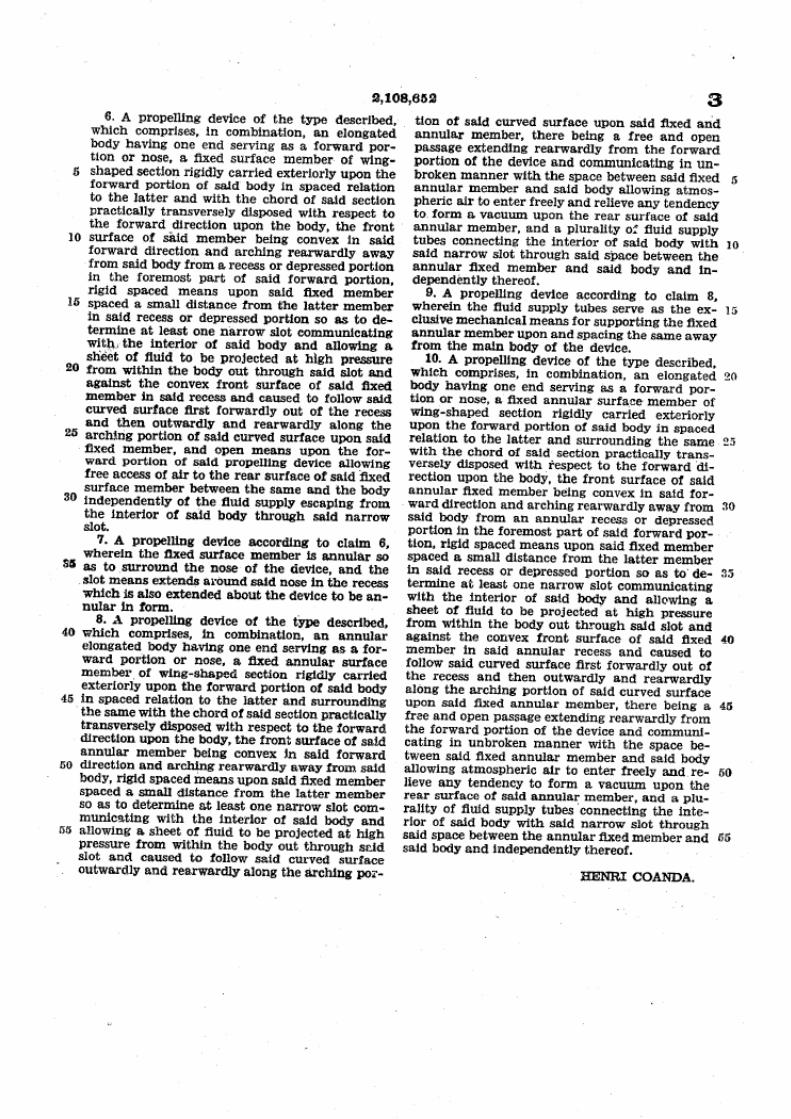
B Henri Coanda’s Propelling Device 82
iii
List of Figures
1 Velocity profile in the boundary layer for laminar flow . . . . . . . 4
2 Interaction between fluid particles and a real surface . . . . . . . . 8
3 Fluid flow over curved and flat surfaces . . . . . . . . . . . . . . 10
4 Behavior of particle flow over a curved surface . . . . . . . . . . 12
5 Flows over a Wing . . . . . . . . . . . . . . . . . . . . . . . . . 14
6 Hot-air Balloon . . . . . . . . . . . . . . . . . . . . . . . . . . . 17
7 Fish’s Swim-Bladder . . . . . . . . . . . . . . . . . . . . . . . . 18
8 Submarine Ballast System . . . . . . . . . . . . . . . . . . . . . 19
9 The vortex process . . . . . . . . . . . . . . . . . . . . . . . . . 23
10 Downwash and wingtip vortices . . . . . . . . . . . . . . . . . . 24
11 Pitot tube . . . . . . . . . . . . . . . . . . . . . . . . . . . . . . 28
12 Venturi tube . . . . . . . . . . . . . . . . . . . . . . . . . . . . . 30
13 Theoretical atomizer . . . . . . . . . . . . . . . . . . . . . . . . 33
14 Air velocity in the tube . . . . . . . . . . . . . . . . . . . . . . . 34
15 dV/dt to achieve the correct velocity . . . . . . . . . . . . . . . . 35
16 Real atomizer . . . . . . . . . . . . . . . . . . . . . . . . . . . . 36
17 Nozzle Detail . . . . . . . . . . . . . . . . . . . . . . . . . . . . 36
18 Flit Gun . . . . . . . . . . . . . . . . . . . . . . . . . . . . . . . 37
19 Restricted exit orifice . . . . . . . . . . . . . . . . . . . . . . . . 38
iv
20 Joule-Thomson apparatus . . . . . . . . . . . . . . . . . . . . . . 39
21 Beard on an organ flue pipe . . . . . . . . . . . . . . . . . . . . . 42
22 Bunsen Burner . . . . . . . . . . . . . . . . . . . . . . . . . . . 43
23 Typical force configuration on an airfoil in an air flow . . . . . . . 45
24 Geometry outside the airfoil . . . . . . . . . . . . . . . . . . . . 48
25 Illustration of the covariant derivative. . . . . . . . . . . . . . . . 49
26 Bending of the airflow by an airfoil. . . . . . . . . . . . . . . . . 51
27 Coanda effect geometry. . . . . . . . . . . . . . . . . . . . . . . 53
28 Detail at the Diffuser Wall . . . . . . . . . . . . . . . . . . . . . 56
29 Early turbojet . . . . . . . . . . . . . . . . . . . . . . . . . . . . 58
30 The entrance cowl for an Airbus A380 turbofan engine . . . . . . 59
31 Ducted fan tailrotor . . . . . . . . . . . . . . . . . . . . . . . . . 59
32 Vortex tube schematic . . . . . . . . . . . . . . . . . . . . . . . . 60
33 Vortex tube flow . . . . . . . . . . . . . . . . . . . . . . . . . . . 60
34 The Dyson Air MultiplierTM
fan . . . . . . . . . . . . . . . . . . 61
35 Operation of the Dyson Air MultiplierTM
fan . . . . . . . . . . . . 61
36 Cross section of the Dyson Air MultiplierTM
fan . . . . . . . . . . 62
37 The Magnus effect . . . . . . . . . . . . . . . . . . . . . . . . . 63
38 Gurney flap . . . . . . . . . . . . . . . . . . . . . . . . . . . . . 63
39 High-lift wing devices . . . . . . . . . . . . . . . . . . . . . . . 64
v
40 Bus burned by the pyroclastic flow from the World Trade Centercollapse on September 11, 2001. . . . . . . . . . . . . . . . . . . 67
vi
Abstract
All aerodynamic forces on a surface are caused by collisions of fluidparticles with the surface. Upwash, downwash, lift, drag, the starting vortex,the bow wave, and any other phenomena that would not occur without thesurface are caused by its presence as it interacts with the air flow. Whilethe standard approach to fluid dynamics, which is founded on the “fluidapproximation,” is effective in providing a means of calculating a wide rangeof fluid behavior, it falters in its ability to account for the effects of complexinteractions of the fluid either with itself, other fluids, or with solid bodies.One of the conditions required to justify the fluid approximation is that theflow be steady [21], i.e. that the particles of the fluid not be interacting witheach other or with any surface. It is these very interactions, however, thatare the causes of aerodynamic effects on solid bodies in the flow. This isnot to say, of course, that the fluid approximation is never useful, but thatsome well-known and important effects such as the Coanda effect are notexplained by that model.
1
1 Preface
The purpose of this paper is to set the stage for a close examination of fluid phe-nomena, an examination at the particle level. Most fluid phenomena of interestare the result of its behavior in interaction with surfaces, other fluids or, indeed,with itself. The eddies and turbulence attendant fluid shear are extremely com-plex. As one fluid is injected into another, the shear effects depend further on thedifferent attributes of the fluids. If a fluid is flowing, it is doing so with respect tosomething, a surface for instance.
A dimensionless quantity used to characterize the nature of fluid flow is Reynolds’number:
R =ρvLη
where
ρ is the density of the fluid,
v is its velocity,
η is the fluid’s viscosity and
L is called “a characteristic length.”
What does “characteristic length” mean? L is a length that is defined only in termsof the boundaries of the flow such as the diameter of a tube or the chord lengthof an airfoil. What length is it and why? In fact, Reynolds’ number is only well-defined in discussions of model scaling of fluid flows in interaction with solidsurfaces. For example the characteristics of a flow around a boat with a beam of4 meters in an ocean current of 10 knots will be the same for a scale model of theboat in the same ocean water whose beam is 0.4 meters and where the current is100 knots.
What meaning can references to Reynolds’ number have?
Bernoulli’s relation involves the fluid velocity. In a Venturi tube, it is the velocitywith respect to the wall of the tube. If a high fluid velocity implies a low pressure,
1
how can the pressure readings in different parts of the tube be different since thesensors are in the boundary layer of the fluid at the surface of the wall of the tube?The boundary layer is stationary, or nearly so (see Figure 1 below).
It is these and other baffling questions that have launched the author into theseinvestigations.
Even though aerodynamics engineers are masters at designing airframes, they arerefining known technology. Without understanding from first principles, light-ing engineers would just be refining incandescent lamps and we would not havefluorescent lights or LEDs.
2 Introduction
The behavior of real fluids, i.e., compressible and viscous, is to this day bafflingin many ways. Part of the reason is that explanations of fluid behavior are hold-overs from the pre-twentieth century belief that a fluid is a fundamental entity, notcomposed of anything else.[2] The trouble with this approach is that it providesonly viscosity and pressure as ways of understanding how the fluid interacts withitself or with solid bodies. Both are intensive variables but what do they mean forin cases where the fluid approximation is not valid?
Pressure, p, (stress normal to a surface) can be understood as that fluid propertywhich causes a normal force on a surface in the flow,
dFn = p(s) dA.
The shear force provides part of the drag on a surface. It is derived from the shearstress, τ , tangential to the surface.
dFs = τ ⊗ dA,
where
2
τ(s)≡ µS(r,s)r=0. (1)
Here,
s is the location on the surface of the airfoil,
r is a length in the direction normal to the surface,
v(s,r) is the velocity of the flow relative to the surface,
µ is the dynamic viscosity of the fluid,F
S(r,s) = ∂v(r,s)/∂ r is the shear and
τ is the resulting shear stress on the surface.
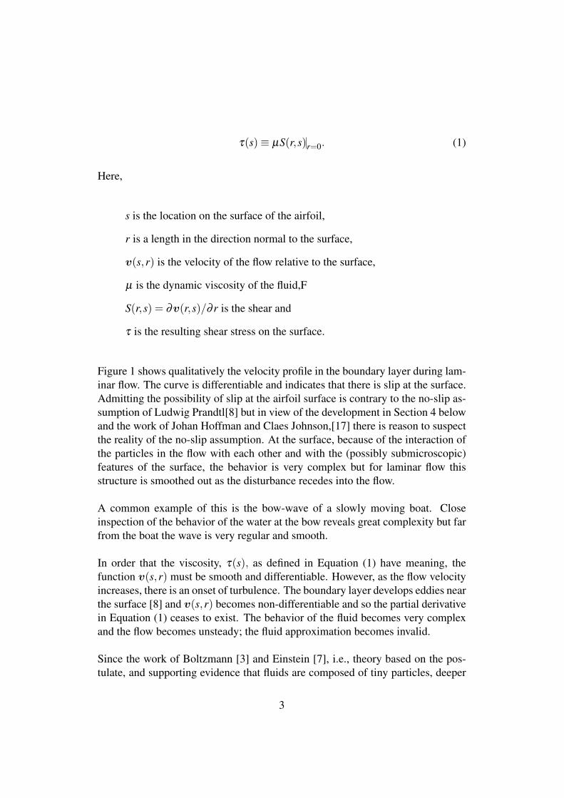
Figure 1 shows qualitatively the velocity profile in the boundary layer during lam-inar flow. The curve is differentiable and indicates that there is slip at the surface.Admitting the possibility of slip at the airfoil surface is contrary to the no-slip as-sumption of Ludwig Prandtl[8] but in view of the development in Section 4 belowand the work of Johan Hoffman and Claes Johnson,[17] there is reason to suspectthe reality of the no-slip assumption. At the surface, because of the interaction ofthe particles in the flow with each other and with the (possibly submicroscopic)features of the surface, the behavior is very complex but for laminar flow thisstructure is smoothed out as the disturbance recedes into the flow.
A common example of this is the bow-wave of a slowly moving boat. Closeinspection of the behavior of the water at the bow reveals great complexity but farfrom the boat the wave is very regular and smooth.
In order that the viscosity, τ(s), as defined in Equation (1) have meaning, thefunction v(s,r) must be smooth and differentiable. However, as the flow velocityincreases, there is an onset of turbulence. The boundary layer develops eddies nearthe surface [8] and v(s,r) becomes non-differentiable and so the partial derivativein Equation (1) ceases to exist. The behavior of the fluid becomes very complexand the flow becomes unsteady; the fluid approximation becomes invalid.
Since the work of Boltzmann [3] and Einstein [7], i.e., theory based on the pos-tulate, and supporting evidence that fluids are composed of tiny particles, deeper
3
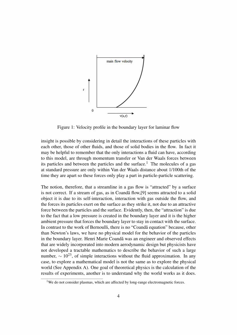
Figure 1: Velocity profile in the boundary layer for laminar flow
insight is possible by considering in detail the interactions of these particles witheach other, those of other fluids, and those of solid bodies in the flow. In fact itmay be helpful to remember that the only interactions a fluid can have, accordingto this model, are through momentum transfer or Van der Waals forces betweenits particles and between the particles and the surface.1 The molecules of a gasat standard pressure are only within Van der Waals distance about 1/100th of thetime they are apart so these forces only play a part in particle-particle scattering.
The notion, therefore, that a streamline in a gas flow is “attracted” by a surfaceis not correct. If a stream of gas, as in Coanda flow,[9] seems attracted to a solidobject it is due to its self-interaction, interaction with gas outside the flow, andthe forces its particles exert on the surface as they strike it, not due to an attractiveforce between the particles and the surface. Evidently, then, the “attraction” is dueto the fact that a low pressure is created in the boundary layer and it is the higherambient pressure that forces the boundary layer to stay in contact with the surface.In contrast to the work of Bernoulli, there is no “Coanda equation” because, otherthan Newton’s laws, we have no physical model for the behavior of the particlesin the boundary layer. Henri Marie Coanda was an engineer and observed effectsthat are widely incorporated into modern aerodynamic design but physicists havenot developed a tractable mathematics to describe the behavior of such a largenumber, ∼ 1023, of simple interactions without the fluid approximation. In anycase, to explore a mathematical model is not the same as to explore the physicalworld (See Appendix A). One goal of theoretical physics is the calculation of theresults of experiments, another is to understand why the world works as it does.
1We do not consider plasmas, which are affected by long-range electromagnetic forces.
4
The miracle is that mathematics is as useful as it is in describing and predictingphysical effects.
The statements made below about fluid flow are conclusions and hypotheses com-ing from a consideration of particles obeying Newton’s laws. The author’s inten-tion is to stimulate the reader’s thoughts about the behavior of fluids in regimeswhere the flow is not steady, and hence the fluid approximation is invalid. Anotheraim of this paper is to discern causes of phenomena. A mathematical equationdoes not contain causal information. For example, the thrust of a rocket is notcaused by the velocity of the exiting gases but by the pressure difference betweenthe throat and the projection along the axis of the motor of the throat area onto theback wall of the motor. Bernoulli’s equation relates the the exit velocity and thepressure difference but conveys no information as to which is the cause and whichis the effect. It is only from experience with the physical world and abstractions ofthat experience that one knows that in Newton’s second law it is force that causesacceleration, not the reverse.
It is hoped that an understanding of the true causes of aerodynamic effects willlead to new aerodynamic designs and the rethinking of designs already created.Imagine, for a moment, that in the absence of a tractable mathematical model,non-mathematical understanding is possible.
3 Total force on the surface of the airfoil
For perfectly elastic collisions the effect on a surface over an area ∆A results in aforce, ∆F with components normal and transverse to the area.
∆F = m∑∆A
ai
where m is the mass of one particle and the ai are the accelerations of the parti-cles hitting the surface area ∆A and the summation is over the area. The normalcomponents of the ai’s are due to pressure and the transverse components are dueto the viscous interaction of the fluid with the surface and with itself.
5
As the particles move over the surface, they are affected by the molecular protu-berances on the surface and by Van der Waals forces between the particles and thesurface. This friction, i.e., viscosity, force is proportional to the area ∆A as well.
The total force on the airfoil, then, is the vector sum of the normal and tangentialforce components over the total airfoil area:
Ftotal =− ∑air f oil
(∆Fn +∆Fs) .
The integral form of this equation is
Ftotal =−∮
air f oil(dFn +dFs) . (2)
The minus sign indicates that the force on the particles is opposite to the force onthe surface of the airfoil. There is sometimes confusion about the above surfaceintegral. It does not mean that there is a net forward flow under the airfoil. Justthat the flow is the vector sum of a translation and a rotation. This rotation isa consequence of the presence of the airfoil in the flow. The surface integral,reduced to a line integral in the case of an infinite wing, just indicates the integralof all forces on all sides of the wing. (See also Section 7 below.) There is aformal derivation of the Kutta-Joukowski theorem at [10] and [11]. Notice that thecirculation integral is conducted in a region of potential flow, where Bernoulli’sequation would hold, i.e., far from the surface. The circulation is an integralof the velocity field around the airfoil. But the Kutta-Joukowski theorem begsthe question as to how this velocity field is created and how it could be derivedmathematically from first principles.
3.1 Physical parameters affecting the pressure on the airfoil
We will ignore Van der Waals forces and assume that the fluid is approximatelyan ideal gas. The equation of state for an ideal gas is
pV = NkT, (3)
6
where
p is the pressure,
V is volume,
T is the Kelvin temperature.
N is the number of particles in V and
k is Boltzmann’s constant, (∼ 1.38×10⁻²³ (m2kg)(sec2 ◦K)
)
We now choose units so that k = 1. Then the particle density, ρ is
ρ =NV
=pT
(4)
Then,
p = ρT. (5)
Far away from the airfoil, the pressure, p, is approximately constant and uniformexcept for the effect of gravity and the presence of the airfoil[11]. The com-pressibility of air can be ignored. But on the surface of the airfoil, it is preciselypressure differential that causes lift. Equation (5) reveals that ρ, and T , subject tothe laws of thermodynamics, are at the disposal of the aeronautical engineer forcreating a favorable pressure field on the airfoil’s surface.
4 Mechanics of fluid interaction
Aerodynamic forces affecting a rigid surface are always net forces produced bydifferences in pressure between different parts of the surface. The absolute pres-sure on a surface area element is the density of the normal components of theforces acting on the surface there.
7
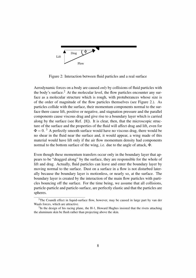
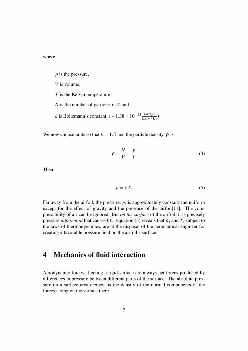
Figure 2: Interaction between fluid particles and a real surface
Aerodynamic forces on a body are caused only by collisions of fluid particles withthe body’s surface.2 At the molecular level, the flow particles encounter any sur-face as a molecular structure which is rough, with protuberances whose size isof the order of magnitude of the flow particles themselves (see Figure 2.). Asparticles collide with the surface, their momentum components normal to the sur-face there cause lift, positive or negative, and stagnation pressure and the parallelcomponents cause viscous drag and give rise to a boundary layer which is carriedalong by the surface (see Ref. [8]). It is clear, then, that the microscopic struc-ture of the surface and the properties of the fluid will affect drag and lift, even forΦ = 0. 3 A perfectly smooth surface would have no viscous drag, there would beno shear in the fluid near the surface and, it would appear, a wing made of thismaterial would have lift only if the air flow momentum density had componentsnormal to the bottom surface of the wing, i.e. due to the angle of attack, Φ.
Even though these momentum transfers occur only in the boundary layer that ap-pears to be “dragged along” by the surface, they are responsible for the whole oflift and drag. Actually, fluid particles can leave and enter the boundary layer bymoving normal to the surface. Dust on a surface in a flow is not disturbed later-ally because the boundary layer is motionless, or nearly so, at the surface. Theboundary layer is created by the interaction of the main flow particles with parti-cles bouncing off the surface. For the time being, we assume that all collisions,particle-particle and particle-surface, are perfectly elastic and that the particles arespheres.
2The Coanda effect in liquid-surface flow, however, may be caused in large part by van derWaals forces, which are attractive.
3In the design of his racing plane, the H-1, Howard Hughes insisted that the rivets attachingthe aluminum skin be flush rather than projecting above the skin.
8
4.1 Fluid flow over a flat surface
Let us consider the flat surface in panel a) of Figure 3. The pressure on the surfaceis due only to the normal components of the momenta of the impacting particles.Flow along such a surface will not affect surface pressure. As particles are blownaway from the surface, other particles are drawn in from outside to replace them.4
Pressure on the surface is due to collisions of particles with the surface. Where theflow has no normal component, the pressure is due only to the thermal motion anddensity of the particles in the boundary layer, i.e. the static atmospheric pressure.Hence this pressure will be a function only of the mass of a particle, the particledensity, and Kelvin temperature of the air at the surface.
In reality, the fluid particles in a layer around a surface boundary seem to be car-ried along with the surface, i.e. the distribution of the components of their veloci-ties parallel to the surface is nearly[17] circularly symmetric about a mean whichis the velocity of the surface relative to the free-stream velocity.5 Particles, aslarge as dust particles or as small as the molecules making up the flow, experienceVan der Waals forces attracting them to the surface. Whether or not the particlesare fixed on the surface by these forces depends on the structure of the moleculesmaking up the flow and those making up the surface. These Van der Waals forcesare responsible for the “wetting” of the surface. In some cases, e.g. Teflon andwater, the fluid drains off the surface quite readily just under the force of gravity.In other cases, e.g. modern motor oil on a bearing surface, the fluid may adherefor months or even years.
In any case, however, particles continually leave the boundary layer and enter ittransversely from the flow due to heat energy or, at an angle of attack, becausethey have velocity components normal to the surface.6 Beyond a mean free path7
or so but still in the boundary layer, the distribution of the normal components ofparticles’ velocities moving toward or away from the surface will depend on thetemperature and density of the particles. Even though it is regularly driven at highspeed, a car will accumulate dust on its body. An air stream directed toward the
4Place a sheet of paper flat on your hands. Blow over the top surface of the paper. Thisexperiment refutes the notion that the pressure in a free flow is less than the ambient static pressure.Bernoulli flow, on the other hand, is (or could be) confined to a tube and is not free.
5This property of fluid flow was utilized by Nicola Tesla [1] in his unique design of a rotarypump.
6It can be seen, then, that dust particles on a surface in an air flow are not disturbed not becausethe fluid particles are necessarily entrained but that they come and go normal to the surface. Hencethey do not impart lateral forces to the dust particles.
7∼ 9×10⁻⁸ meters for N2 at standard pressure and temperature.
9
surface, however, will blow off some of that dust. As we will see, it is the mutualinteraction of flow particles and these “stagnant” boundary layer particles that isresponsible for a part of the lift on an airfoil at subsonic speeds.
An increase in the free-stream velocity means that the components of the veloc-ities of the flow particles increase in the direction of the free-stream velocity andparallel to the surface. The reason that the boundary layer remains quiescent, ornearly so, is that the components of the colliding particles’ velocities parallel tothe surface reverse as they collide with microscopic irregularities. This is one ofthe causes of aerodynamic drag and accounts for the fluid’s viscosity.8 If the col-lisions are not perfectly elastic, the rebound speed is less than the incident speedand the surface absorbs some of the particle’s energy, i.e. it heats up.
4.2 Fluid flow over a curved surface
Figure 3: Fluid flow over curved and flat surfaces
In a steady flow over a surface, stream particles have only thermal velocity com-ponents normal to the surface. If the surface is flat, the particles that collide withboundary layer particles are as likely to knock them out of the boundary layer as toknock others in, i.e. the boundary layer population is not changed and the pressureon the surface is the same as if there were no flow. If, however, the surface curvesaway from the flow direction, the particles in the flow will tend to take directionstangent to the surface, i.e. away from the surface, obeying Newton’s first law.As these particles flow away from the surface, their collisions with the boundarylayer thermal particles tend to knock those particles away from the surface. Whatthis means is that if all impact parameters are equally likely, there are more ways
8Though viscosity is supposed to be a property of the fluid, it is measured by the terminalvelocity of a ball in the fluid or the force it takes to slide two plates with the fluid between them.Viscosity, then, has to do with the interaction of the fluid with itself as well as with solid bodies.
10
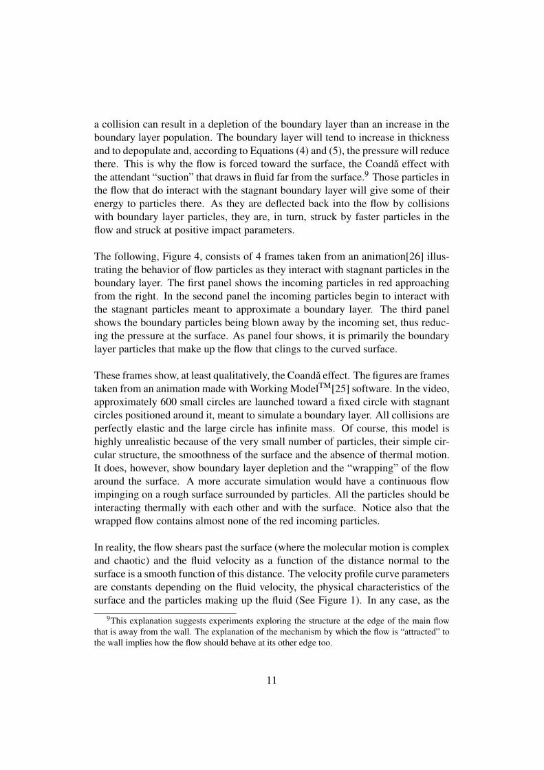
a collision can result in a depletion of the boundary layer than an increase in theboundary layer population. The boundary layer will tend to increase in thicknessand to depopulate and, according to Equations (4) and (5), the pressure will reducethere. This is why the flow is forced toward the surface, the Coanda effect withthe attendant “suction” that draws in fluid far from the surface.9 Those particles inthe flow that do interact with the stagnant boundary layer will give some of theirenergy to particles there. As they are deflected back into the flow by collisionswith boundary layer particles, they are, in turn, struck by faster particles in theflow and struck at positive impact parameters.
The following, Figure 4, consists of 4 frames taken from an animation[26] illus-trating the behavior of flow particles as they interact with stagnant particles in theboundary layer. The first panel shows the incoming particles in red approachingfrom the right. In the second panel the incoming particles begin to interact withthe stagnant particles meant to approximate a boundary layer. The third panelshows the boundary particles being blown away by the incoming set, thus reduc-ing the pressure at the surface. As panel four shows, it is primarily the boundarylayer particles that make up the flow that clings to the curved surface.
These frames show, at least qualitatively, the Coanda effect. The figures are framestaken from an animation made with Working ModelTM[25] software. In the video,approximately 600 small circles are launched toward a fixed circle with stagnantcircles positioned around it, meant to simulate a boundary layer. All collisions areperfectly elastic and the large circle has infinite mass. Of course, this model ishighly unrealistic because of the very small number of particles, their simple cir-cular structure, the smoothness of the surface and the absence of thermal motion.It does, however, show boundary layer depletion and the “wrapping” of the flowaround the surface. A more accurate simulation would have a continuous flowimpinging on a rough surface surrounded by particles. All the particles should beinteracting thermally with each other and with the surface. Notice also that thewrapped flow contains almost none of the red incoming particles.
In reality, the flow shears past the surface (where the molecular motion is complexand chaotic) and the fluid velocity as a function of the distance normal to thesurface is a smooth function of this distance. The velocity profile curve parametersare constants depending on the fluid velocity, the physical characteristics of thesurface and the particles making up the fluid (See Figure 1). In any case, as the
9This explanation suggests experiments exploring the structure at the edge of the main flowthat is away from the wall. The explanation of the mechanism by which the flow is “attracted” tothe wall implies how the flow should behave at its other edge too.
11
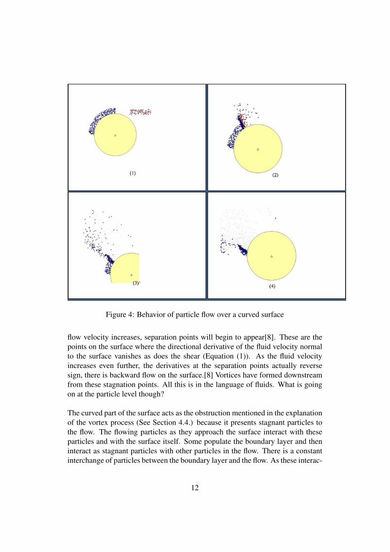
Figure 4: Behavior of particle flow over a curved surface
flow velocity increases, separation points will begin to appear[8]. These are thepoints on the surface where the directional derivative of the fluid velocity normalto the surface vanishes as does the shear (Equation (1)). As the fluid velocityincreases even further, the derivatives at the separation points actually reversesign, there is backward flow on the surface.[8] Vortices have formed downstreamfrom these stagnation points. All this is in the language of fluids. What is goingon at the particle level though?
The curved part of the surface acts as the obstruction mentioned in the explanationof the vortex process (See Section 4.4.) because it presents stagnant particles tothe flow. The flowing particles as they approach the surface interact with theseparticles and with the surface itself. Some populate the boundary layer and theninteract as stagnant particles with other particles in the flow. There is a constantinterchange of particles between the boundary layer and the flow. As these interac-
12
tions take place the process described above activates the boundary layer particleslike falling dominoes, causing the enveloping flow. When the surface curves awayfrom the flow, the flow particles, obeying Newton’s first law, tend to travel on tra-jectories tangent to the surface and thus leave its vicinity, taking some boundarylayer particles with them. This reduced pressure in the boundary layer has twoeffects. First, it causes the higher pressure in the main flow to force itself, andsmoke streamers, toward the surface, and second, it results in lift as the higherpressure on the bottom of the wing has increased effect.
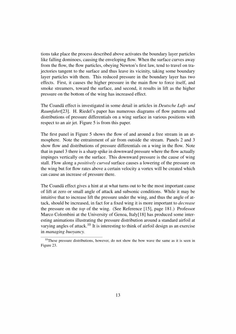
The Coanda effect is investigated in some detail in articles in Deutsche Luft- undRaumfahrt[23]. H. Riedel’s paper has numerous diagrams of flow patterns anddistributions of pressure differentials on a wing surface in various positions withrespect to an air jet. Figure 5 is from this paper.
The first panel in Figure 5 shows the flow of and around a free stream in an at-mosphere. Note the entrainment of air from outside the stream. Panels 2 and 3show flow and distributions of pressure differentials on a wing in the flow. Notethat in panel 3 there is a sharp spike in downward pressure where the flow actuallyimpinges vertically on the surface. This downward pressure is the cause of wingstall. Flow along a positively curved surface causes a lowering of the pressure onthe wing but for flow rates above a certain velocity a vortex will be created whichcan cause an increase of pressure there.
The Coanda effect gives a hint at at what turns out to be the most important causeof lift at zero or small angle of attack and subsonic conditions. While it may beintuitive that to increase lift the pressure under the wing, and thus the angle of at-tack, should be increased, in fact for a fixed wing it is more important to decreasethe pressure on the top of the wing. (See Reference [15], page 181.) ProfessorMarco Colombini at the University of Genoa, Italy[18] has produced some inter-esting animations illustrating the pressure distribution around a standard airfoil atvarying angles of attack.10 It is interesting to think of airfoil design as an exercisein managing buoyancy.
10These pressure distributions, however, do not show the bow wave the same as it is seen inFigure 23.
13
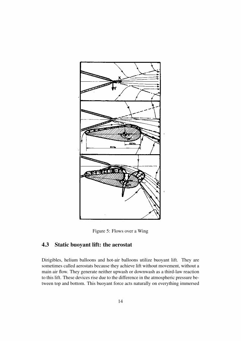
Figure 5: Flows over a Wing
4.3 Static buoyant lift: the aerostat
Dirigibles, helium balloons and hot-air balloons utilize buoyant lift. They aresometimes called aerostats because they achieve lift without movement, without amain air flow. They generate neither upwash or downwash as a third-law reactionto this lift. These devices rise due to the difference in the atmospheric pressure be-tween top and bottom. This buoyant force acts naturally on everything immersed
14
in a fluid in a gravitational field. It acts on us but we don’t notice it because thedensity of our bodies is so much greater than the density of air where we live.Archimedes noticed this buoyant force and uttered the famous “Eυρηκα !” Hehad discovered how to measure the density of the king’s crown and to test if it waspure gold.
One might think that the buoyant force, which is due to the gravitational field,would be negligible for an airplane because the airplane’s overall density is muchgreater than air at standard conditions. However, see Section 6 below. Since thebuoyant force is due to the pressure differential between the top of a body and thebottom as well as the overall density of the balloon, the buoyancy can be managedby controlling these pressures and the density.
In France a balloon large enough to carry cargo is called a Montgolfière after thebrothers who in 1783 flew the first hot-air balloon to carry a living cargo.
A balloon, or aerostat, consists of an envelope filled with a gas that is lighter thanair, i.e. less dense. This gas can consist of molecules each of which is lighter thanthe average weight of the molecules of air or air itself that is hotter and less densethan the atmosphere surrounding the aerostat. The light molecules of Helium orHydrogen are used for the former type of aerostat.
4.3.1 Light gas Balloon
The ideal gas equation, Equation (4) above, is:
ρ =pT
=NV,
where ρ is the number density of the molecules, i.e., the number of molecules perunit volume, and we’ve chosen units so that k = 1.
Archimedes’ equation for the buoyant force, B, on an object immersed in a fluidis
B = ρ f m f gV, (6)
15
where
ρ f is the density of the particles of fluid in which the body is immersed,
m is the average mass of a fluid particle,
V is the volume of the immersed object and
g is the acceleration due to gravity.
This upward force is offset by the weight of the object immersed,
wballoon = ρgmggV +wenvelope, (7)
where here ρg is the density of the gas in the balloon, mg is the mass of a gasparticle and the V ′s are the same. The net upward force, then, is
Fnet = B−wballoon = (ρ f m f −ρgmg)gV.−wenvelope. (8)
Assuming that the temperatures of the gas inside the balloon and the outside theballoon are equal, for a balloon with a loose, light, flexible and very voluminousenvelope, the atmospheric pressure and the pressure inside the balloon are thesame so, according to Equation (3),
ρ f = ρg = ρ, (9)
and the net upward force is proportional to m f −mg, (ignoring the weight of theenvelope), i.e.,
Fnet ∝ (m f −mg). (10)
This is why a light gas like Hydrogen or Helium is used in high-altitude balloons.
If the envelope of the balloon is an elastic material like rubber, the pressure exertedby the envelope on the gas within is an increasing function of the volume of the
16
balloon. The pressure inside the balloon is pg = p f + penvelope, which means thatin this case ρg > ρ f . A rubber balloon will only rise if ρgmg < ρ f m f , and thenonly until ρ f = ρg(mg/m f ) or the elastic limit of the rubber is reached and theballoon explodes.
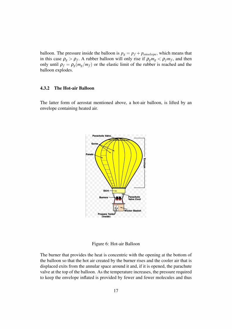
4.3.2 The Hot-air Balloon
The latter form of aerostat mentioned above, a hot-air balloon, is lifted by anenvelope containing heated air.
Figure 6: Hot-air Balloon
The burner that provides the heat is concentric with the opening at the bottom ofthe balloon so that the hot air created by the burner rises and the cooler air that isdisplaced exits from the annular space around it and, if it is opened, the parachutevalve at the top of the balloon. As the temperature increases, the pressure requiredto keep the envelope inflated is provided by fewer and fewer molecules and thus
17
the weight of the balloon decreases. By the intermittent operation of the burnerand the parachute valve, the pilot can very precisely choose the height of theballoon.
All the forces that result in the lift force, buoyant or dynamical, are due to colli-sions of molecules with the envelope.
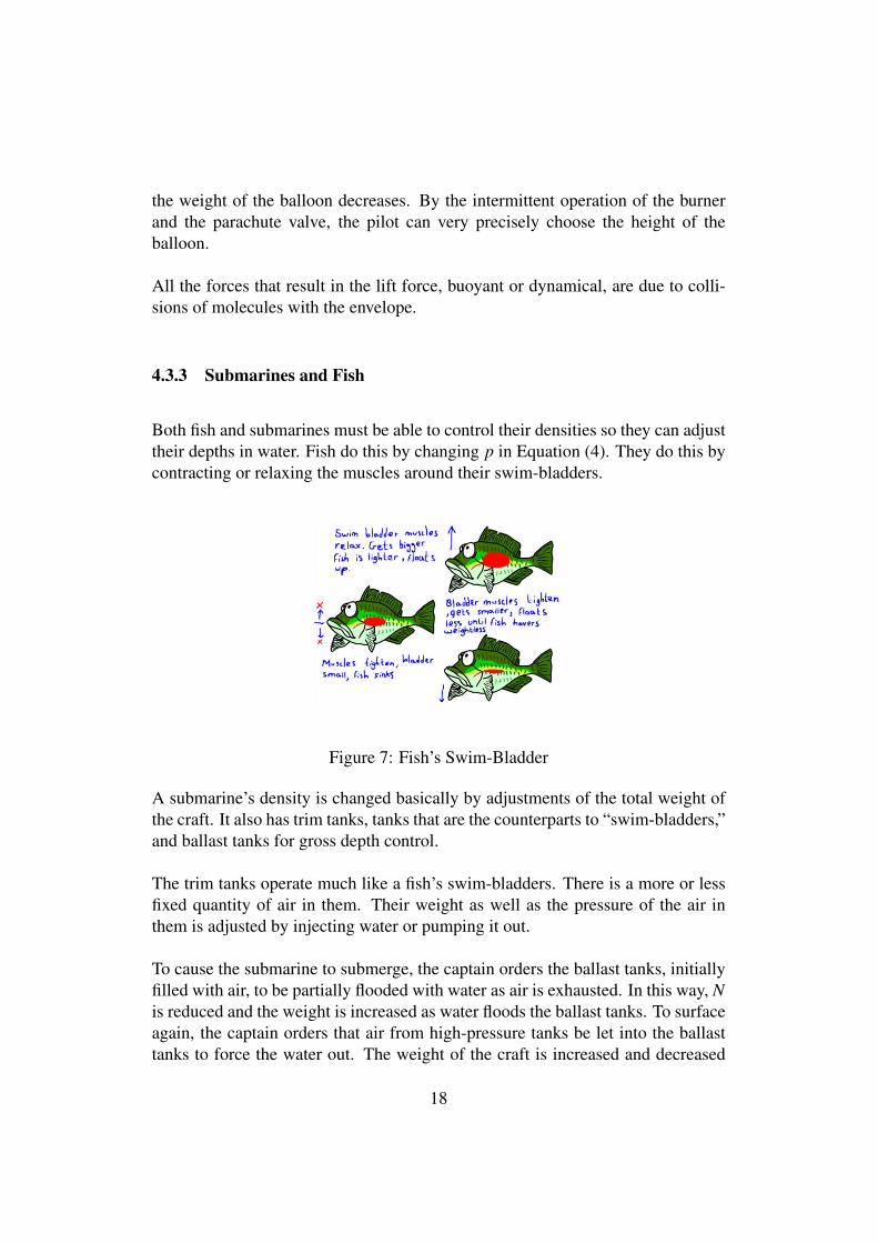
4.3.3 Submarines and Fish
Both fish and submarines must be able to control their densities so they can adjusttheir depths in water. Fish do this by changing p in Equation (4). They do this bycontracting or relaxing the muscles around their swim-bladders.
Figure 7: Fish’s Swim-Bladder
A submarine’s density is changed basically by adjustments of the total weight ofthe craft. It also has trim tanks, tanks that are the counterparts to “swim-bladders,”and ballast tanks for gross depth control.
The trim tanks operate much like a fish’s swim-bladders. There is a more or lessfixed quantity of air in them. Their weight as well as the pressure of the air inthem is adjusted by injecting water or pumping it out.
To cause the submarine to submerge, the captain orders the ballast tanks, initiallyfilled with air, to be partially flooded with water as air is exhausted. In this way, Nis reduced and the weight is increased as water floods the ballast tanks. To surfaceagain, the captain orders that air from high-pressure tanks be let into the ballasttanks to force the water out. The weight of the craft is increased and decreased
18
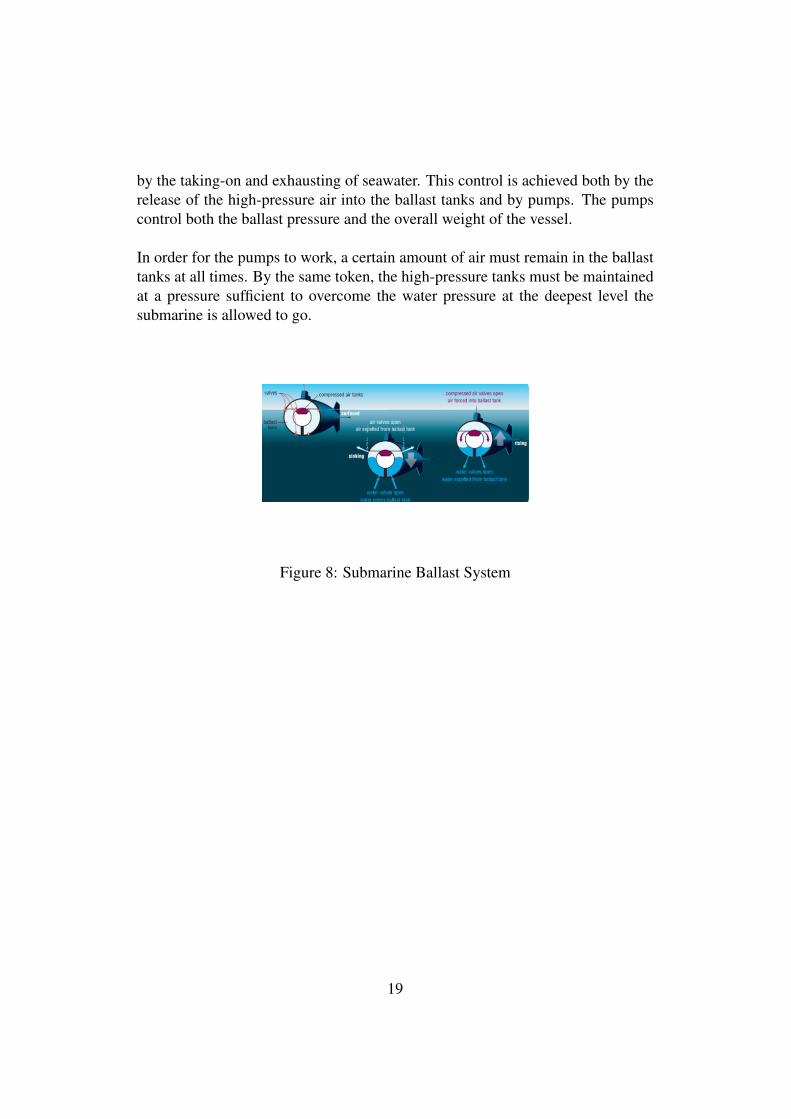
by the taking-on and exhausting of seawater. This control is achieved both by therelease of the high-pressure air into the ballast tanks and by pumps. The pumpscontrol both the ballast pressure and the overall weight of the vessel.
In order for the pumps to work, a certain amount of air must remain in the ballasttanks at all times. By the same token, the high-pressure tanks must be maintainedat a pressure sufficient to overcome the water pressure at the deepest level thesubmarine is allowed to go.
Figure 8: Submarine Ballast System
19
***********
In addition to its own weight a container of gas has weight due to the gravitationalforce which affects each molecule of the gas inside. In the gas there is a densitygradient toward the earth. Newton’s law of gravitation is:
F =−rMm/r3, (11)
where r is the vector from the centre of the earth to the particle.
As they collide with one another molecules, in general, will have momentum com-ponents in any given direction due their temperature but they will always have adownward momentum component due to their acceleration in the gravitationalfield.
mv = m(vheat +vdown). (12)
This downward component will always be a factor in collisions with other par-ticles and will be transmitted in each collision according to Newton’s third law.The momentum transfer to the envelope from the molecules on the bottom will begreater than the molecules at the top just because of the greater particle densitythere. The top molecules exert a force upward and the molecules on the bottomexert a downward force. In a vacuum the difference between these forces is thatpart of the weight of the object that is due to the gas inside.
If the container is in the earth’s atmosphere there is also a buoyant force. Thisforce is also due to the gravity force. The external atmosphere is denser at thebottom of the envelope than at the top, hence the number of exterior atmosphericmolecular collisions per second at the bottom of the envelope is greater than atthe top. The difference between the number and force of the collisions per secondon the bottom (molecules with upward velocity components) and that on the top(downward components) is the buoyant force. If the buoyant force is greater thanits total weight, the container rises.
The number density, ρ(y), of molecules inside the envelope is a monotonicallydecreasing function of the height. This is due to the influence of gravity on eachmolecule. If hot air molecules are injected into the envelope those molecules willundergo collisions with the molecules they encounter.
20
Consider a hot molecule that enters with energy,
∆E = k∆T, (13)
where k is Boltzmann’s constant and ∆T is the temperature of the entering molecule.Again, we choose units for which k = 1.
Consider two regions: upper and lower. In each, according to Equation (4),
p = ρT. (14)
Although the densities and temperatures of the two regions differ, there is onlyone pressure, p, at the point of entry. Hence,
ρu×Tu = ρd×Td, (15)
and
Tu =ρd
ρu×Td. (16)
This molecule’s energy will be shared among the molecules it collides with andtheir added energy will be shared as they interact with others.
Assume the molecule is knocked upward. The resulting increase in temperaturein that region, u , compared with the lower region, d, will be,
∆Tu =ρd(y)ρu(y)
×∆Td, (17)
and similarly for the case where the entering molecule is knocked down. If theentering molecule is knocked upward, there will be fewer molecules to share itsenergy than if it were knocked downward since, due to the gravity field,
21
ρu(y)< ρd(y). (18)
The absorption of its energy there will cause a rise in temperature greater than ifit were knocked downward. If it is knocked downward, the denser aggregation ofmolecules there will also absorb the molecule’s energy but the rise in temperaturewill be less. It is not just that the hot air molecules themselves rise, it is also theirenergy which is transmitted upward as they collide with molecules already there.
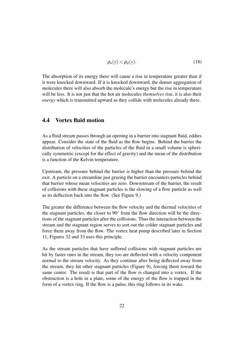
4.4 Vortex fluid motion
As a fluid stream passes through an opening in a barrier into stagnant fluid, eddiesappear. Consider the state of the fluid as the flow begins. Behind the barrier thedistribution of velocities of the particles of the fluid in a small volume is spheri-cally symmetric (except for the effect of gravity) and the mean of the distributionis a function of the Kelvin temperature.
Upstream, the pressure behind the barrier is higher than the pressure behind theexit. A particle on a streamline just grazing the barrier encounters particles behindthat barrier whose mean velocities are zero. Downstream of the barrier, the resultof collisions with these stagnant particles is the slowing of a flow particle as wellas its deflection back into the flow. (See Figure 9.)
The greater the difference between the flow velocity and the thermal velocities ofthe stagnant particles, the closer to 90◦ from the flow direction will be the direc-tions of the stagnant particles after the collisions. Thus the interaction between thestream and the stagnant region serves to sort out the colder stagnant particles andforce them away from the flow. The vortex heat pump described later in Section11, Figures 32 and 33 uses this principle.
As the stream particles that have suffered collisions with stagnant particles arehit by faster ones in the stream, they too are deflected with a velocity componentnormal to the stream velocity. As they continue after being deflected away fromthe stream, they hit other stagnant particles (Figure 9), forcing them toward thesame center. The result is that part of the flow is changed into a vortex. If theobstruction is a hole in a plate, some of the energy of the flow is trapped in theform of a vortex ring. If the flow is a pulse, this ring follows in its wake.
22
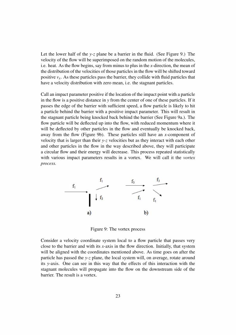
Let the lower half of the y-z plane be a barrier in the fluid. (See Figure 9.) Thevelocity of the flow will be superimposed on the random motion of the molecules,i.e. heat. As the flow begins, say from minus to plus in the x-direction, the mean ofthe distribution of the velocities of those particles in the flow will be shifted towardpositive vx. As these particles pass the barrier, they collide with fluid particles thathave a velocity distribution with zero mean, i.e. the stagnant particles.
Call an impact parameter positive if the location of the impact point with a particlein the flow is a positive distance in y from the center of one of these particles. If itpasses the edge of the barrier with sufficient speed, a flow particle is likely to hita particle behind the barrier with a positive impact parameter. This will result inthe stagnant particle being knocked back behind the barrier (See Figure 9a.). Theflow particle will be deflected up into the flow, with reduced momentum where itwill be deflected by other particles in the flow and eventually be knocked back,away from the flow (Figure 9b). These particles still have an x-component ofvelocity that is larger than their y-z velocities but as they interact with each otherand other particles in the flow in the way described above, they will participatea circular flow and their energy will decrease. This process repeated statisticallywith various impact parameters results in a vortex. We will call it the vortexprocess.
Figure 9: The vortex process
Consider a velocity coordinate system local to a flow particle that passes veryclose to the barrier and with its x-axis in the flow direction. Initially, that systemwill be aligned with the coordinates mentioned above. As time goes on after theparticle has passed the y-z plane, the local system will, on average, rotate aroundits y-axis. One can see in this way that the effects of this interaction with thestagnant molecules will propagate into the flow on the downstream side of thebarrier. The result is a vortex.
23
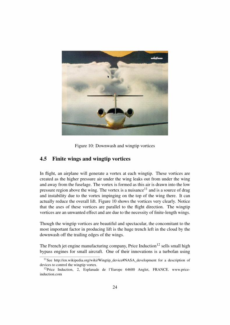
Figure 10: Downwash and wingtip vortices
4.5 Finite wings and wingtip vortices
In flight, an airplane will generate a vortex at each wingtip. These vortices arecreated as the higher pressure air under the wing leaks out from under the wingand away from the fuselage. The vortex is formed as this air is drawn into the lowpressure region above the wing. The vortex is a nuisance11 and is a source of dragand instability due to the vortex impinging on the top of the wing there. It canactually reduce the overall lift. Figure 10 shows the vortices very clearly. Noticethat the axes of these vortices are parallel to the flight direction. The wingtipvortices are an unwanted effect and are due to the necessity of finite-length wings.
Though the wingtip vortices are beautiful and spectacular, the concomitant to themost important factor in producing lift is the huge trench left in the cloud by thedownwash off the trailing edges of the wings.
The French jet engine manufacturing company, Price Induction12 sells small highbypass engines for small aircraft. One of their innovations is a turbofan using
11See http://en.wikipedia.org/wiki/Wingtip_device#NASA_development for a description ofdevices to control the wingtip vortex.
12Price Induction, 2, Esplanade de l’Europe 64600 Anglet, FRANCE. www.price-induction.com
24
composite, non-metallic blades. At speed, the fan blades elongate and actuallyseal on the special bearing surface of the fan housing. The reason for this is toeliminate vortices at the vane tips. This reduces power requirements, increasesthe engine efficiency and increases thrust.
4.6 Leading Edge Extensions
Though wingtip vortices are unwanted, similar vortices are created on purpose byso-called Leading Edge Extension (LEX) surfaces.[22] A LEX is a flat surfaceextending a short distance from the fuselage and from near the cockpit aft to theleading edge of the wing. At angle of attack vortices are created as the high-pressure air flows from below the LEX to the lower pressure above. This causesthe vortices, clockwise on the left side and counter-clockwise on the right. Thesevortices extend back over the wings and interrupt the stalling vortices that wouldotherwise form over the wing. They blow away the particles that would causehigh pressure on the tops of the wings, especially near the roots. LEXs allow theplane to operate at higher angles of attack than it otherwise could.
4.7 Birds in flight
The high-speed camera shows some very interesting aspects of birds taking flight.[6]Perhaps the most interesting is that on take-off, when maximum lift is needed, abird’s power stroke is down and forward, not backward as it would do if it were“swimming” in the air. This motion both pressurizes the air under the wing andcreates upwash13 on the leading edges of its wings. This upwash flows over theleading edge and actually contributes to lowering the pressure on the top of thewing.
On aircraft, the leading edge slots and slats are designed to control and makeuse of upwash. Trailing edge flaps act like the big feathers on the trailing edgesof a bird’s wings. They help trap the flow and thus increase pressure under thewing and they also extend the wing’s curved surface and hence the region of lowpressure on the top of the wing.
13See Section 15
25
5 Bernoulli flow and Coanda flow
5.1 Bernoulli’s equation
For an incompressible14 fluid in steady[21] flow, a simple expression for the con-servation of energy was derived by Daniel Bernoulli in 1737 in his book “Hydro-dynamica”. In steady flow, the fluid can be enveloped in an actual or virtual tube.That means that at any cross-section perpendicular to the tube’s walls, the fluidhas a uniform velocity across the tube, i.e. there can be no shear in the fluid. Fluidneither leaves nor enters through the wall of the tube and the particles do not inter-act with each other or with the wall of the tube. And finally, since the flow mustbe laminar, the tubes themselves, actual or abstract, are restricted to a smooth,gently varying shape. These assumptions preclude turbulence or eddy formation.If these conditions hold to a good approximation, Bernoulli’s equation holds. Ifsuch a tube cannot be drawn, the equation does not hold. Bernoulli’s equationallows the calculation of general behavior but because of these assumptions thetheory is not able to predict other aspects of fluid dynamics, such as behavior inthe boundary layer of a surface in the flow.
Bernoulli’s equation is:
Energy Density =12
ρv2 +ρgh+ p. (19)
where
p is the absolute pressure,
ρ is the density of the fluid,
g is the acceleration due to gravity,
h is the height in the gravitational field and
v is the velocity vector for a cell in the flow small enough so that the veloc-ities of the particles in the cell are approximately equal.
14See, however http://www.efunda.com/formulae/fluids/bernoulli.cfm for a more general formof the equation which describes the behavior of certain types of compressible fluids.
26
Note that the assumption that the flow consists of these cells amounts to the fluidapproximation. In the particle view the existence of these cells is not assumedand the macroscopic fluid velocity is superimposed on thermal components ofthe particles’ velocities. When the flow is incompressible and steady, the energydensity is conserved in the flow.
Bernoulli’s equation is an expression of the conservation of energy, a checksumthat is very useful in the calculation of the properties of a steady flow. It doesnot speak to the question of cause and effect however. Fluid flow is caused by apressure differential or direct collisions of the fluid particles with surfaces, e.g. apropellor, and is sustained according to Newton’s first law since the particles aremassive. In some circumstances a flow can also give rise to a pressure differen-tial, the cause of the Coanda effect. Just because a fluid is flowing does not meanthat the pressure within the fluid has decreased. Velocity is relative to the inertialframe where it is measured but pressure is a quantity independent of the inertialframe where it is measured. The pressure in a fluid is measured as the momen-tum transfer of the fluid particles striking some transducer that produces a pointerreading. The force that moves the pointer is the integral over the (oriented) surfacearea of the transducer of the rate the fluid particles transfer momentum to it.
Pointer Reading ∝ F orce = m× ∑transducer
sur f ace
dvdt⊗dA, (20)
where m and v are the particle’s mass and velocity and dA is an area element.We assume that the particle collisions with the surface are perfectly elastic, so thetensor product, ⊗, gives a result normal to the surface element, dA.
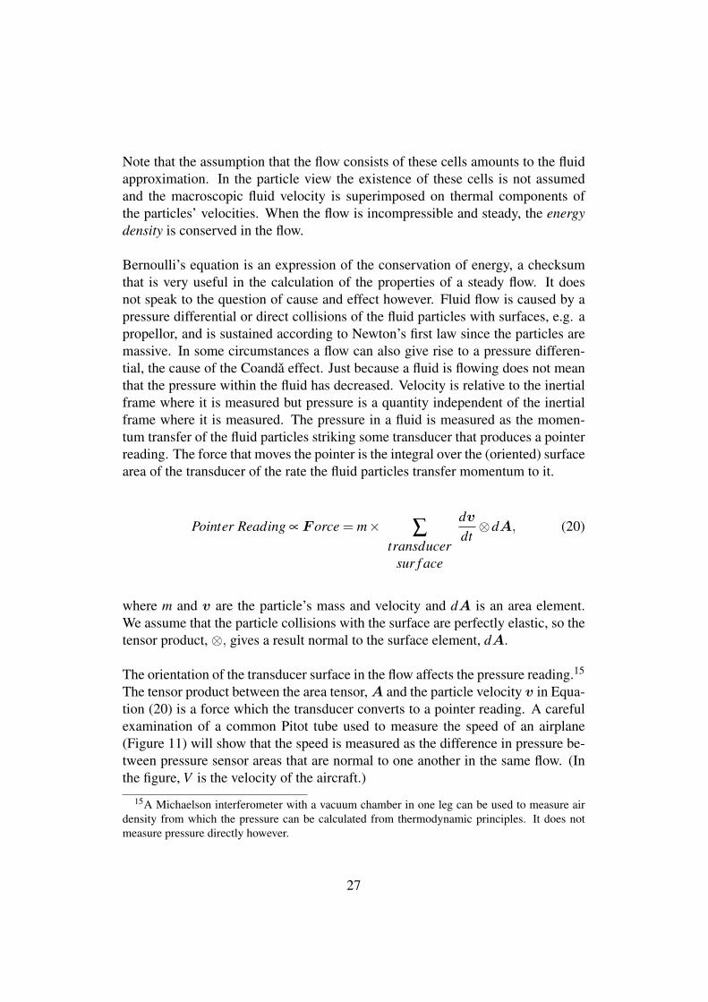
The orientation of the transducer surface in the flow affects the pressure reading.15
The tensor product between the area tensor, A and the particle velocity v in Equa-tion (20) is a force which the transducer converts to a pointer reading. A carefulexamination of a common Pitot tube used to measure the speed of an airplane(Figure 11) will show that the speed is measured as the difference in pressure be-tween pressure sensor areas that are normal to one another in the same flow. (Inthe figure, V is the velocity of the aircraft.)
15A Michaelson interferometer with a vacuum chamber in one leg can be used to measure airdensity from which the pressure can be calculated from thermodynamic principles. It does notmeasure pressure directly however.
27
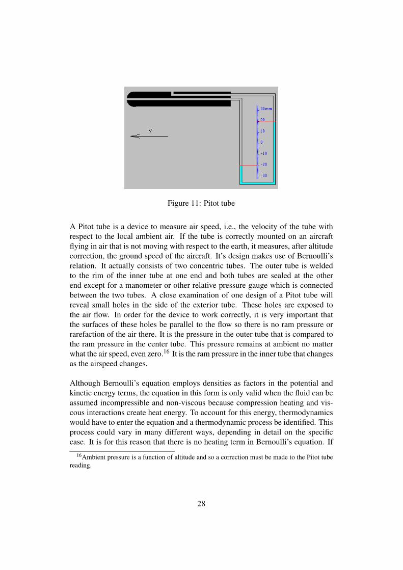
Figure 11: Pitot tube
A Pitot tube is a device to measure air speed, i.e., the velocity of the tube withrespect to the local ambient air. If the tube is correctly mounted on an aircraftflying in air that is not moving with respect to the earth, it measures, after altitudecorrection, the ground speed of the aircraft. It’s design makes use of Bernoulli’srelation. It actually consists of two concentric tubes. The outer tube is weldedto the rim of the inner tube at one end and both tubes are sealed at the otherend except for a manometer or other relative pressure gauge which is connectedbetween the two tubes. A close examination of one design of a Pitot tube willreveal small holes in the side of the exterior tube. These holes are exposed tothe air flow. In order for the device to work correctly, it is very important thatthe surfaces of these holes be parallel to the flow so there is no ram pressure orrarefaction of the air there. It is the pressure in the outer tube that is compared tothe ram pressure in the center tube. This pressure remains at ambient no matterwhat the air speed, even zero.16 It is the ram pressure in the inner tube that changesas the airspeed changes.
Although Bernoulli’s equation employs densities as factors in the potential andkinetic energy terms, the equation in this form is only valid when the fluid can beassumed incompressible and non-viscous because compression heating and vis-cous interactions create heat energy. To account for this energy, thermodynamicswould have to enter the equation and a thermodynamic process be identified. Thisprocess could vary in many different ways, depending in detail on the specificcase. It is for this reason that there is no heating term in Bernoulli’s equation. If
16Ambient pressure is a function of altitude and so a correction must be made to the Pitot tubereading.
28
compression is significant, Bernoulli’s equation in this form cannot be expectedto hold.17
5.2 Bernoulli at the particle level
Strictly speaking, Bernoulli’s equation does not apply over a real free surfacebecause particles will move lateral to the flow after striking protuberances on thesurface, violating a Bernoulli assumption.18
Think of a pressure vessel of a non-viscous gas feeding a Bernoulli tube (a realone, glass). Before flow starts, the energy in the vessel is equally distributedbetween the 3 degrees of freedom. When the fluid is vented into the tube, thepressure in the tube is less than that in the vessel. If the venting is sudden, apressure wave will travel in the tube at the speed of sound and thus will precedethe air flow.
The reason that the pressure in the exit tube is less than in the vessel is that theonly particles that exit into the tube are those with velocity components in the exitdirection. Of course these particles exert a transverse pressure lower than that ofthe vessel since they are selected for their momentum components being outwardinto the tube. Because energy is conserved, these particles’ initial energy densityis now apportioned between pressure on the walls of the tube (the pressure readby manometer) and the kinetic energy density of their velocity in the tube, 1
2ρv2.This means that there will be a lower manometer reading in the exit pipe than inthe vessel. The pressure difference between the vessel and the end of the exit pipeallows the flow of the exiting particles. At the particle level, Bernoulli’s equation,where the exit tube is in the x-direction, is:
pvessel =12
ρ ∑(v2x + v2
y + v2z ) = ptube +
12
ρ ∑v2x , (21)
where the sums are over the velocities of the all particles in the flow and
17See http://www.efunda.com/formulae/fluids/bernoulli.cfm18If the diameter of a real tube is much greater than the size of the wall’s microscopic protuber-
ances, the tube is a Bernoulli tube to a good approximation, however.
29
ptube =12
ρ ∑(v2y + v2
z ) (22)
is the pressure at the tube wall.
At the exit orifice, it is just those particles that are moving toward the hole thatactually exit. The hole is a sorting mechanism hence the entropy decreases in theexit flow. This sorting process at the exit selects particles that will give a lowerpressure when that pressure is measured at an orifice whose plane is parallel to theflow, such as a manometer connection.
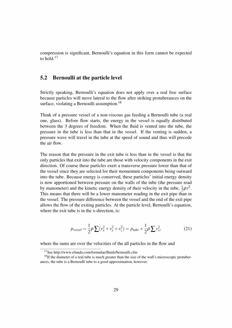
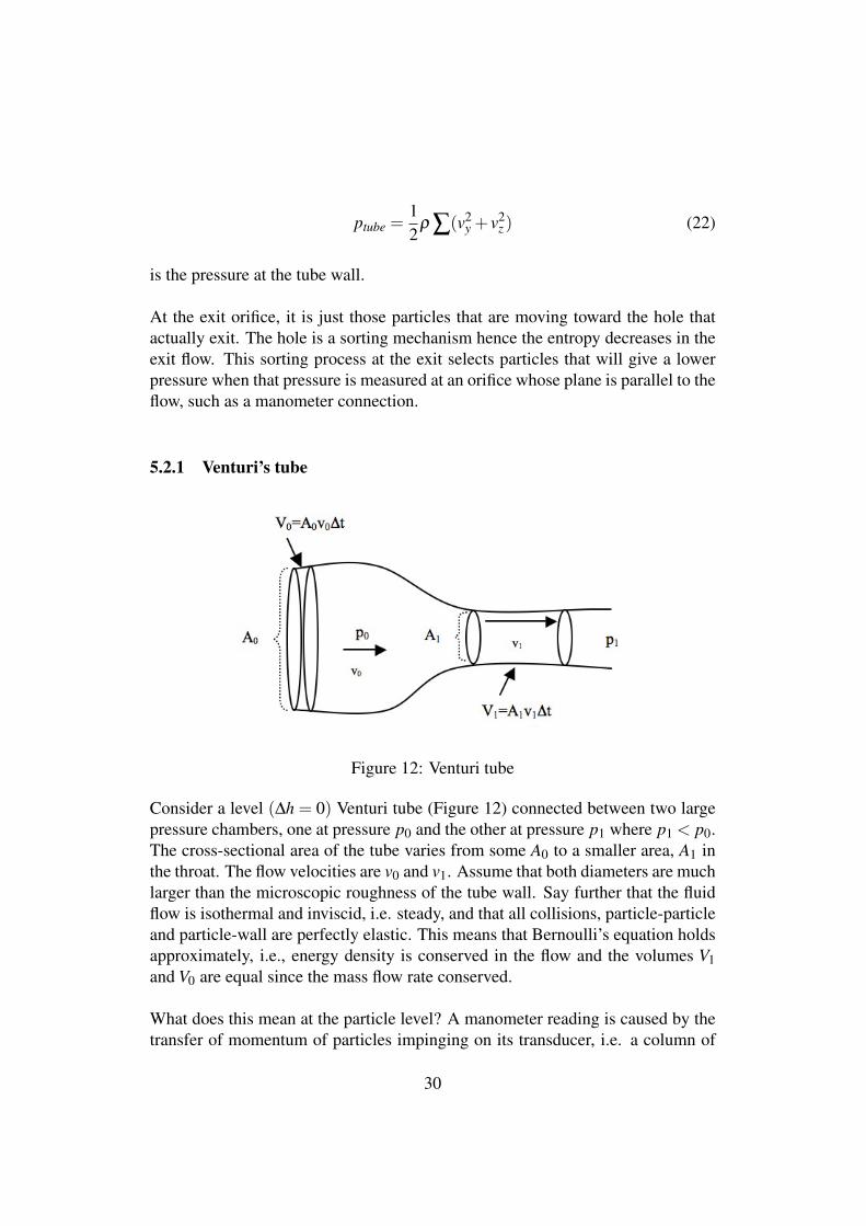
5.2.1 Venturi’s tube
Figure 12: Venturi tube
Consider a level (∆h = 0) Venturi tube (Figure 12) connected between two largepressure chambers, one at pressure p0 and the other at pressure p1 where p1 < p0.The cross-sectional area of the tube varies from some A0 to a smaller area, A1 inthe throat. The flow velocities are v0 and v1. Assume that both diameters are muchlarger than the microscopic roughness of the tube wall. Say further that the fluidflow is isothermal and inviscid, i.e. steady, and that all collisions, particle-particleand particle-wall are perfectly elastic. This means that Bernoulli’s equation holdsapproximately, i.e., energy density is conserved in the flow and the volumes V1and V0 are equal since the mass flow rate conserved.
What does this mean at the particle level? A manometer reading is caused by thetransfer of momentum of particles impinging on its transducer, i.e. a column of
30
liquid, a diaphragm or some other object whose reaction is converted to a pointerreading. These recording devices convert the transfer of the particles’ transversemomenta to a force normal to the transducing surface.
When an orifice is opened in a pressure vessel, it sorts out and allows to exit thoseparticles which are at the orifice and which have velocity components in the direc-tion of the plane of the orifice. The components of the exiting particles’ velocitiesnormal to the orifice will necessarily be smaller than those of particles which donot exit. (See Equation (21)) If a manometer is fitted to the wall of the tube, thetransverse pressure can be measured at the entrance. As the tube’s diameter de-creases, there is a further sorting process so that the pressure in that section islower still. Particles in the tube that are outside the imaginary projection of thenarrow tube back into the larger section, will strike the curving wall of the neckand interact with other particles. They bounce off elastically with undiminishedenergy and with a change of momentum. They will then energize the particlesnear the small-diameter exit tube. The result of these interactions is the conserva-tion of energy and the transfer of the energy in the annulus to the particles in thesmaller tube.
Rewriting Equation (19) with h = 0 and adding some more detail, we get
12
mV0
∑(v2x + v2
y + v2z )0 =
12
mV1
∑(v2x + v2
y + v2z )1, (23)
,
where the sums are over the particles in V0 and V1 respectively. With the mainfluid velocity in the x−direction, the conservation of mass yields
(vx)0 =A1
A0(vx)1 . (24)
where v is the average velocity component.
Further, since V0 = V1 = V we replace ∑v2 by Nv2 where N is the number ofparticles in the volumes V0 and V1, and put ρ = mN
V . The pressures measured bymanometers in V0 and V1 are, respectively, p0 =
12ρ(v2
y + v2z )0 and p1 =
12ρ(v2
y +
v2z )1 so, with some algebra, we have the Venturi relation,
31
(vx)1 =
√√√√√2(P0−P1)
ρ
[1−(
A1A0
)2] . (25)
It is clear from this development, then, that the higher velocity in the Venturithroat is not the cause of the lower pressure there. The lower pressure and thehigher velocity are both due to the sorting effect of the narrowing tube and thecomplex interactions of the particles as they enter the throat.
There is an interesting result of Bernoulli’s equation in the form of Equation (23)and a result of Statistical Mechanics. According to Statistical Mechanics, the rootmean square of the molecular speed, vrms is related only to the temperature, T andthe molecular mass, not to the pressure, P.
12
mv2rms =
32
kBT,
where kB is Boltzmann’s constant, and thus no matter what p0 is, (vx)0 cannotexceed the molecular speed, vrms, corresponding to the temperature T ! This iswhy it is important and fortunate that the high pressure in a rocket motor is createdas an effect of high temperature. The beneficial effect of high temperature inrocket propulsion will be seen below in Section 9.
5.2.2 The two-fluid atomizer
Atomizers are often cited as examples of devices that make use of the Bernoulliprinciple. Figure 13 is an illustration of what is commonly understood to be atwo-fluid atomizer.
The vessel on the left represents a flexible bulb filled with air. The pressure p1is created when someone squeezes the bulb. Although the molecules of air aremoving in the bulb, their motion is random in every direction so, at the macro-scopic level and under the fluid approximation, the velocity v1 = 0. When the airis flowing steadily in the horizontal tube, however, pressure p2 and velocity v2develop.
32
Figure 13: Theoretical atomizer
The vertical tube is connected to the atomizer and its lower part is submergedin the liquid meant to be atomized and mixed with the air. The air velocity inthe vertical tube is zero. Finally the mixture is expelled into the atmosphere atpressure pa. Below are the parameters in the regions of the apparatus:
p1 is the pressure in the bulb,
p2 and v2 obtain in the horizontal tube,
pa is the atmospheric pressure and
h is the liquid height in the vertical tube.
If we assume that the air density, ρ , is constant then Bernoulli’s equations become
p0 = p2 +12
ρv22
andp2 +ρwgh = pa,
where ρw is the density of the liquid in the reservoir.
33
These relations result in
pgauge =12
ρv22−ρwgh (26)
where pgauge = p1− pa is the gauge pressure in the bulb and g is the accelerationdue to gravity. Equation (26) shows that the height of the liquid is a function ofboth the air velocity, v2, and the gauge pressure, pgauge, in the bulb. This relationalso predicts that if the bulb is squeezed suddenly, the height, h, will be negative.The pressure pulse travels a the speed of sound but the atomizer can only functioncorrectly when v2 has had time to build up. Figures 14 and 15 illustrate this dualdependence.
Figure 14: Air velocity in the tube
Figure 14 shows the air velocity in the tube, as a function of pgauge, required tolift the atomizer liquid a distance of 5 cm. The next figure, Figure 15, shows thevolume rate of change in the bulb required as a function of D, the tube diameter.
Even for the smallest tube diameter, 1mm, the volume rate of change in the bulbmust be about 20cm3/sec to raise the liquid 5cm. This is a clue as to why conven-tional atomizers are not designed like this.
34
Figure 15: dV/dt to achieve the correct velocity
5.2.3 Conventional atomizer
In many physics books Figure 13, or its equivalent, is displayed as a schematicof an actual two-fluid atomizer. A search of patent disclosures for two-fluid at-omizers reveals, however, that none of them is designed like this. Figure 16 is adiagram of a conventional two-fluid atomizer.
The pressure is applied from the ball on the left. High-pressure air exits the innertube on the right and sweeps first the air from the conical volume and then thefluid from the chamber connected to the reservoir as it is “drawn up” by the lowpressure created in the dotted area. This process is detailed in Figure 17.
The particles with arrows exit the high pressure tube and collide directly with themolecules of the other fluid, mixing with them and sweeping them away and outof the nozzle. In order to achieve the best mixing and delivery, the detailed designof this region is very important.
It is also important to note that, in this mixing and ejection region, Bernoulli’sassumptions do not hold so Bernoulli’s equation cannot be used. Recall thatBernoulli’s equation assumes that there is no interaction between the fluids nor
35
Figure 16: Real atomizer
Figure 17: Nozzle Detail
with the surfaces in the flow. In the case of a two-fluid atomizer, however, mixingand delivery are the two important goals.
36
5.2.4 Flit gun
Figure 18 is a diagram of the famous “Flit Gun” bug sprayer.
Figure 18: Flit Gun
The air stream exiting the gun passes over the tube and interacts with the fluid init. First a partial vacuum is created in the tube then the liquid rises in the tubeand mixes with the air exiting the pump. The angle, θ < 90◦, is crucial as are thedistances, s and d. If, for example, θ ≥ 90◦, the liquid will be forced back into thereservoir. Bernoulli’s equation does not hold for this extremely unsteady flow.
5.2.5 Flow into an expansion chamber
Figure 19 shows an apparatus in which high-velocity air from a low pressure re-gion flows into a chamber at lower pressure. We refer to the sections in the figureas Sections 1,2,3,4 and a, the region under atmospheric pressure.
It is important to remember Equation (21) when thinking about the pressures in thedifferent sections. Bernoulli’s equation, Equation (19), does not rule out p3 < p4in Figure 19. In fact that happens when the pressure, p1, is high enough. Itmay seem counterintuitive that the fluid can flow from a lower pressure into a
37
Figure 19: Restricted exit orifice
higher one but the forward momentum of the high velocity particles incomingfrom Section 3 is greater than that of those already in Section 4, i.e.,
(mvx)3 > (mvx)4,
and thus the particles entering win in the contest of collisions with the particlesin Section 4 and actually enter that section. In contradistinction to the situationupstream where the pressures are decreasing and the interparticle interaction isnegligible, there are now many collisions between particles. In the process, theenergy of forward motion of the entering gas is in part converted into internalenergy of the gas, i.e. heat, pressure and molecular energy of vibration and ro-tation, depending on the structure of the gas molecules. We can call this partialthermalization because some of the kinetic energy of the molecules in translationinto Section 4 is converted to heat and internal molecular excitation, while someappears as macroscopic eddies and turbulence.
Later, in Section 9 of this paper, we will see how the temperature of the fluidflowing into a region like Section 4 of Figure 19 but with an open end to theatmosphere can cause a thrust enhancement in a rocket engine.
38
5.3 The Joule-Thomson effect
The above situation lies somewhere between the case of Bernoulli flow, i.e. noparticle interaction in a smoothly flowing fluid, and the behavior of a real, self-interacting gas which produces the Joule-Thomson[4] effect. In this latter regimethe effects of particle collisions are of paramount importance.
Instead of Equation (19), we will use the form below for the specific energy den-sity as the conservation law.
12
v2 +w = constant (27)
where w is the enthalpy,
w = ε + p/ρ (28)
and ε is the thermodynamic energy per unit mass of the gas. This is the energy ofinteratomic oscillation (in case of polyatomic gases) and rotation of the moleculesas well as their potential energy due to the van der Waals forces between them.
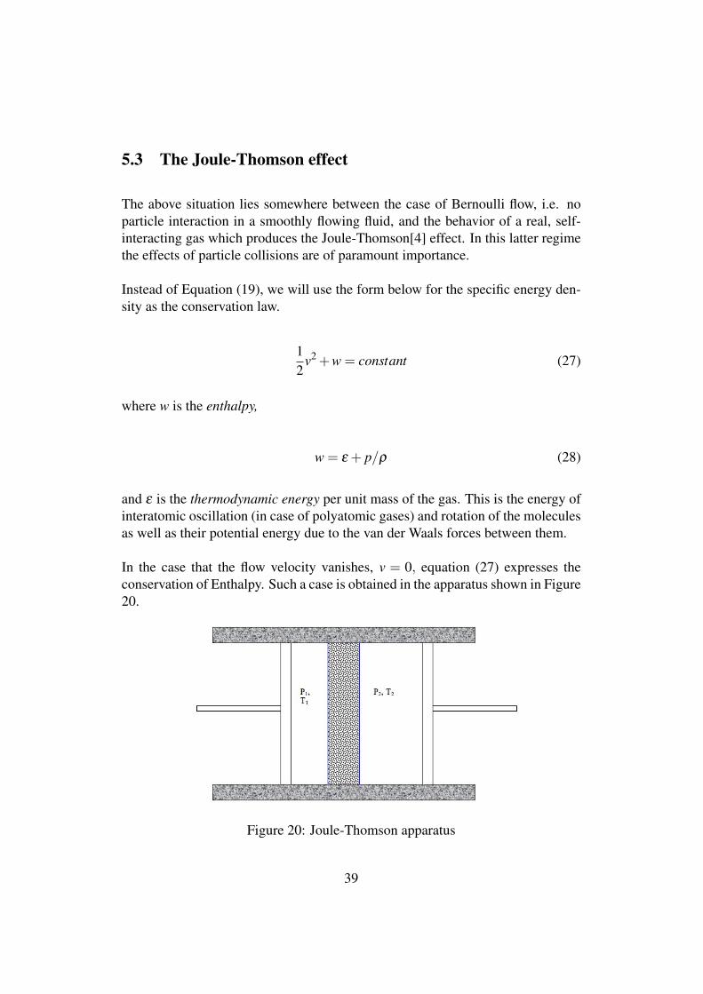
In the case that the flow velocity vanishes, v = 0, equation (27) expresses theconservation of Enthalpy. Such a case is obtained in the apparatus shown in Figure20.
Figure 20: Joule-Thomson apparatus
39
In order that the thermodynamic process be adiabatic, i.e. no heat flowing in orout, the apparatus is insulated. The piston on the left provides pressure, P1 attemperature T1, and the gas moves to the chamber on the right, at pressure P2and temperature T2 by passing through a so-called “porous plug” made of packedgranules of a chemically non-interacting substance, for example frit made of sil-ica. As the gas molecules bounce in chaotic fashion against each other and thefrit particles, the flow velocity is transformed into random motion and thermo-dynamic energy. The following quote is taken from the Wikipedia article on theJoule-Thomson effect:
“As a gas expands, the average distance between molecules grows. Becauseof intermolecular attractive forces (Van der Waals forces), expansion causesan increase in the potential energy of the gas. If no external work is ex-tracted in the process and no heat is transferred, the total energy of the gasremains the same because of the conservation of energy. The increase inpotential energy thus implies a decrease in kinetic energy and therefore intemperature.
A second mechanism has the opposite effect. During gas molecule col-lisions, kinetic energy is temporarily converted into potential energy. As theaverage intermolecular distance increases, there is a drop in the number ofcollisions per time unit, which causes a decrease in average potential en-ergy. Again, total energy is conserved, so this leads to an increase in kineticenergy (temperature). Below the Joule-Thomson inversion temperature, theformer effect (work done internally against intermolecular attractive forces)dominates, and free expansion causes a decrease in temperature. Above theinversion temperature, gas molecules move faster and so collide more often,and the latter effect (reduced collisions causing a decrease in the average po-tential energy) dominates: Joule-Thomson expansion causes a temperatureincrease.”[4]
A device called a “heat pump,” using an appropriate gas, can be a heater or coolerdepending on how the pressures P1 and P2 are adjusted.
6 The Coanda effect
This effect, first investigated and employed by the Romanian aerodynamics en-gineer Henri Marie Coanda (1886 – 1972), usually refers to the phenomenon inwhich an air flow attaches to an adjacent wall which curves away from this flow.
40
(see [8] pp. 42, 664). Another aspect of this phenomenon is the entrainment ofmolecules far from the jet (see the three panels in 5). The attachment effect istaken for granted and it is the separation of the flow from an aerodynamic bodythat is discussed as a precursor to the stalling of the surface ([8] p. 40). The effectcan be seen in some automobile advertisements. Streamers of smoke are seen tohug the profile of a car in a wind tunnel even as the surface of the car curves awayfrom the flow. This behavior indicates a lower pressure that aerodynamicists callsuction at that part of the surface. This is puzzling since there are no long-distanceattractive forces acting in a gas or between the gas molecules and a surface undernormal19 conditions. Figure 3 in section 4.2 discusses the mechanism for suction.
6.1 Organ pipe beard
The Coanda effect is exploited in the design of large flue pipes in some pipe or-gans.20 These pipes are like huge whistles and can, if they are overblown, soundthe octave rather than the fundamental tone. Anyone who has played an Irishtinwhistle knows this effect. Much of the awesome power of the grand organ,however, comes from the volume of the bass notes. The pipe sounds when a sheetof air is blown over the mouth. Some of this air enters the pipe and of course itmust also exit. The only exit from these closed pipes is the mouth itself. The exitpath, then, starts at the top of the mouth of the pipe. The unwanted octave soundswhen air exiting from the mouth interferes with the wind sheet entering the pipe.How, then, to avoid this interference?
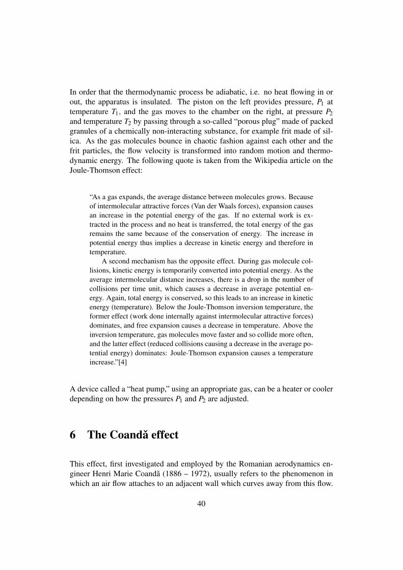
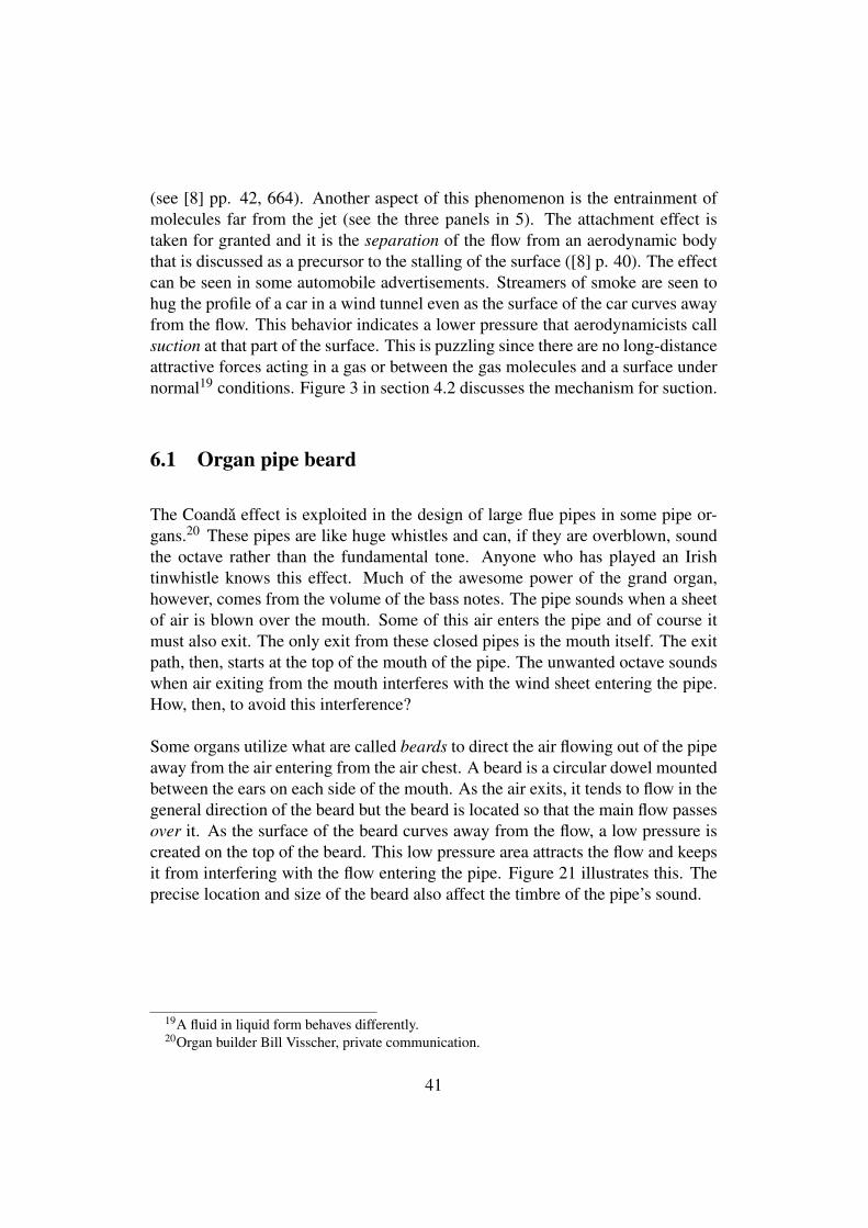
Some organs utilize what are called beards to direct the air flowing out of the pipeaway from the air entering from the air chest. A beard is a circular dowel mountedbetween the ears on each side of the mouth. As the air exits, it tends to flow in thegeneral direction of the beard but the beard is located so that the main flow passesover it. As the surface of the beard curves away from the flow, a low pressure iscreated on the top of the beard. This low pressure area attracts the flow and keepsit from interfering with the flow entering the pipe. Figure 21 illustrates this. Theprecise location and size of the beard also affect the timbre of the pipe’s sound.
19A fluid in liquid form behaves differently.20Organ builder Bill Visscher, private communication.
41
Figure 21: Beard on an organ flue pipe
6.2 The Bunsen burner
A common application of the effect illustrated in Figure 5 is the Bunsen burner.An exploded view is shown in Figure 22 below.
The effect shown in the first panel of Figure 5 is utilized in the Bunsen burner andany other burner where the fuel and air is mixed upstream of the flame. The needlevalve regulates the rate of fuel flow and the Coanda effect causes the mixing as itdraws in air from outside the burner.
42
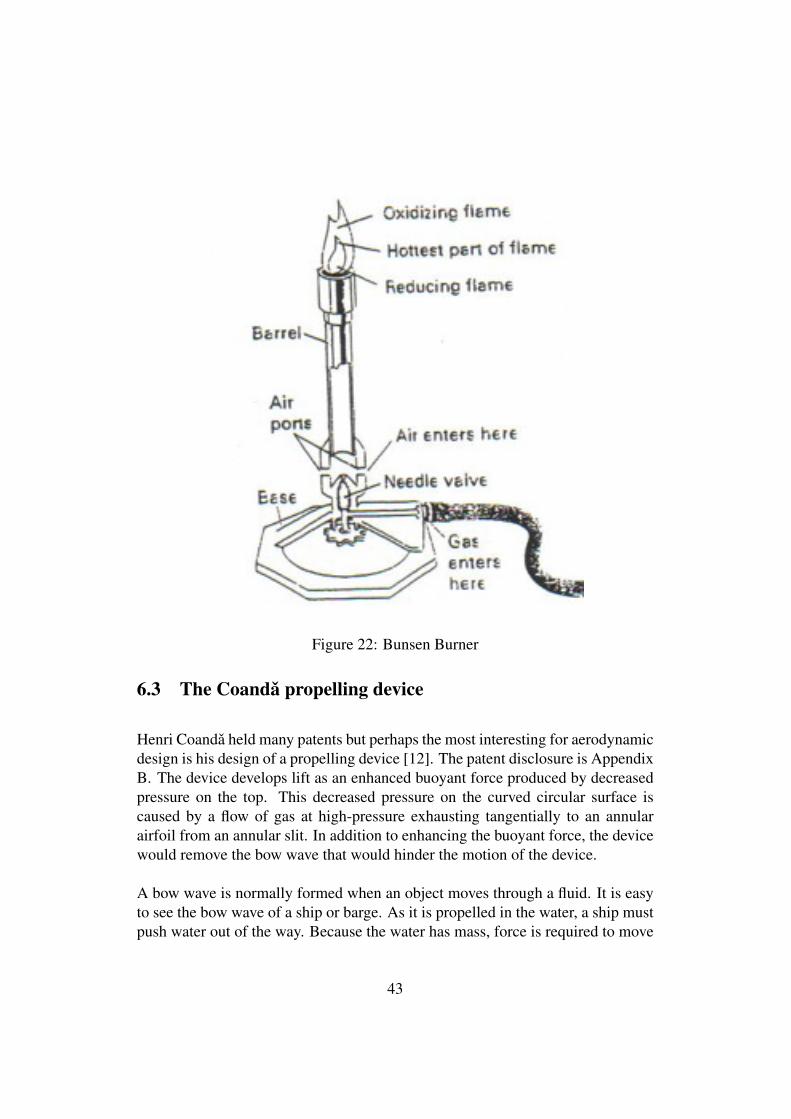
Figure 22: Bunsen Burner
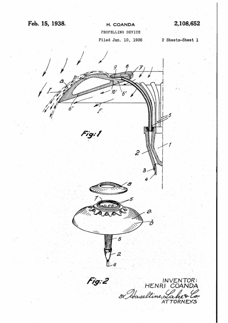
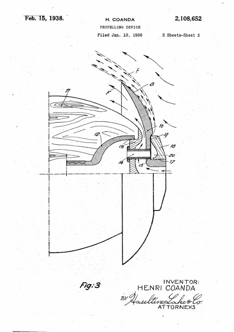
6.3 The Coanda propelling device
Henri Coanda held many patents but perhaps the most interesting for aerodynamicdesign is his design of a propelling device [12]. The patent disclosure is AppendixB. The device develops lift as an enhanced buoyant force produced by decreasedpressure on the top. This decreased pressure on the curved circular surface iscaused by a flow of gas at high-pressure exhausting tangentially to an annularairfoil from an annular slit. In addition to enhancing the buoyant force, the devicewould remove the bow wave that would hinder the motion of the device.
A bow wave is normally formed when an object moves through a fluid. It is easyto see the bow wave of a ship or barge. As it is propelled in the water, a ship mustpush water out of the way. Because the water has mass, force is required to move
43
it. By Newton’s third law, there is an equal and opposite force exerted on the ship.This effect causes drag in addition to the viscous drag of the hull of the ship as itmoves through the water.
A toy helium balloon rises much more slowly than if it weren’t hindered by a bowwave in the air. It is primarily the force of the bow wave that is responsible forthe phenomenon of terminal velocity. By extending his arms and legs, a skydivercan control the terminal velocity, increasing or decreasing it. Figures 1 and 3 ofAppendix B illustrate the dissipation of the bow wave by the Coanda propellingdevice.
7 Calculation of lift
Lift is caused by the collisions of fluid particles with the surface of the airfoil. ByNewton’s third law, this interaction of the particles with the surface results in anequal and opposite reaction on the airflow itself; the particles bounce back. Say,for example, that the lift force is in the “up" direction, then the third law force onthe air is “down."21 The lift can be represented in two ways: 1) as the summationof all the forces on the surface or, according to Newton’s third law, 2) by thenegative of the force the surface exerts on the air. The latter is the approach thatled to the Kutta-Joukowski theorem.22
Figure 23 shows a typical force configuration on the surface of an airfoil.[14] Theair flow is from the left. Note that the primary contribution to the lift is from thecurved surface of the top of the wing. This lowered pressure, the so-called suction,created there also causes the Coanda effect.
The flow particles far from the airfoil’s surface “feel” this suction as a sort ofreverse bow wave and, as a result, flow toward the surface. The low pressure,maintained by the flow past the curved surface, results in a pressure gradient,∂P/∂ξ , that decreases to zero as ξ increases.23 The pressure approaches the limitp∞, the ambient pressure. ξ is the normal distance from the airfoil’s surface.
21Here, we are only concerned with the lift force on heavier than air craft. The situation isdifferent for aerostats.
22See Reference [15] pages 236 and 237.23or more precisely the pressure gradient due to gravity
44
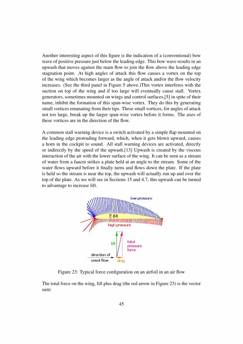
Another interesting aspect of this figure is the indication of a (conventional) bowwave of positive pressure just below the leading edge. This bow wave results in anupwash that moves against the main flow to join the flow above the leading edgestagnation point. At high angles of attack this flow causes a vortex on the topof the wing which becomes larger as the angle of attack and/or the flow velocityincreases. (See the third panel in Figure 5 above.)This vortex interferes with thesuction on top of the wing and if too large will eventually cause stall. Vortexgenerators, sometimes mounted on wings and control surfaces,[5] in spite of theirname, inhibit the formation of this span-wise vortex. They do this by generatingsmall vortices emanating from their tips. These small vortices, for angles of attacknot too large, break up the larger span-wise vortex before it forms. The axes ofthese vortices are in the direction of the flow.
A common stall warning device is a switch activated by a simple flap mounted onthe leading edge protruding forward, which, when it gets blown upward, causesa horn in the cockpit to sound. All stall warning devices are activated, directlyor indirectly by the speed of the upwash.[13] Upwash is created by the viscousinteraction of the air with the lower surface of the wing. It can be seen as a streamof water from a faucet strikes a plate held at an angle to the stream. Some of thewater flows upward before it finally turns and flows down the plate. If the plateis held so the stream is near the top, the upwash will actually run up and over thetop of the plate. As we will see in Sections 15 and 4.7, this upwash can be turnedto advantage to increase lift.
Figure 23: Typical force configuration on an airfoil in an air flow
The total force on the wing, lift plus drag (the red arrow in Figure 23) is the vectorsum:
45
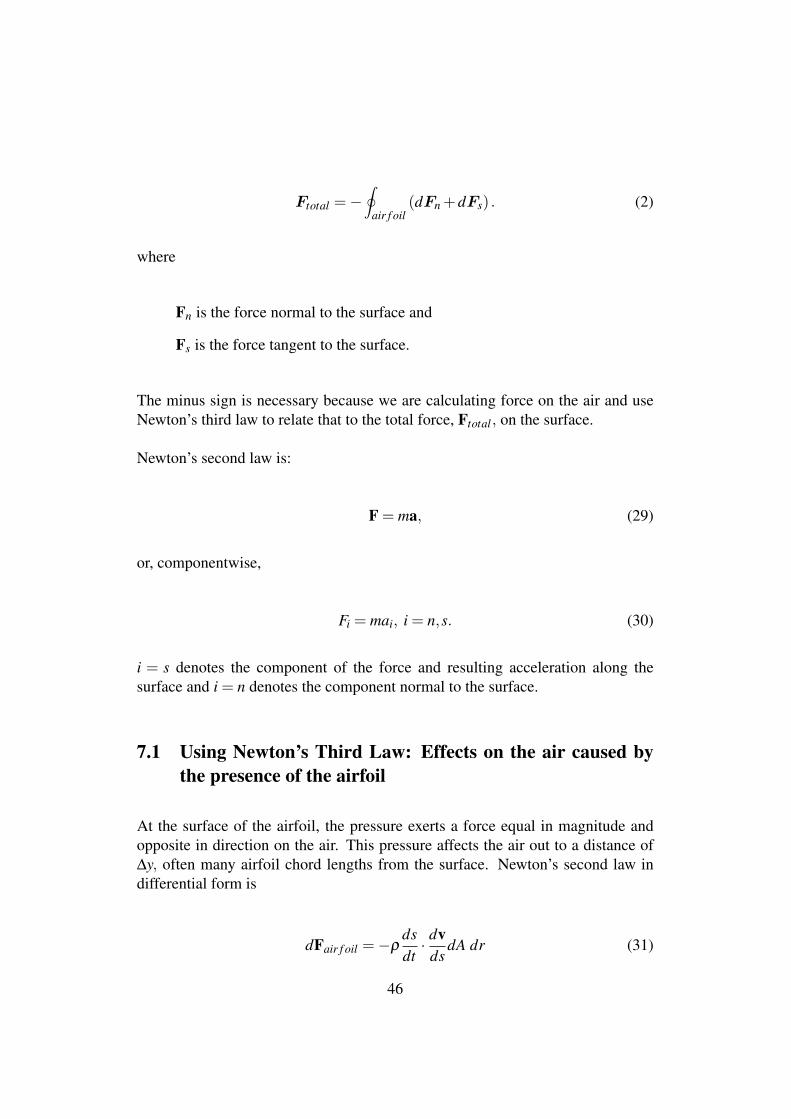
Ftotal =−∮
air f oil(dFn +dFs) . (2)
where
Fn is the force normal to the surface and
Fs is the force tangent to the surface.
The minus sign is necessary because we are calculating force on the air and useNewton’s third law to relate that to the total force, Ftotal, on the surface.
Newton’s second law is:
F = ma, (29)
or, componentwise,
Fi = mai, i = n,s. (30)
i = s denotes the component of the force and resulting acceleration along thesurface and i = n denotes the component normal to the surface.
7.1 Using Newton’s Third Law: Effects on the air caused bythe presence of the airfoil
At the surface of the airfoil, the pressure exerts a force equal in magnitude andopposite in direction on the air. This pressure affects the air out to a distance of∆y, often many airfoil chord lengths from the surface. Newton’s second law indifferential form is
dFair f oil =−ρdsdt· dv
dsdA dr (31)
46
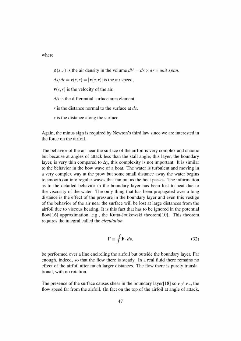
where
ρ(s,r) is the air density in the volume dV = ds×dr×unit span.
ds/dt = v(s,r) = v(s,r) is the air speed,
v(s,r) is the velocity of the air,
dA is the differential surface area element,
r is the distance normal to the surface at ds.
s is the distance along the surface.
Again, the minus sign is required by Newton’s third law since we are interested inthe force on the airfoil.
The behavior of the air near the surface of the airfoil is very complex and chaoticbut because at angles of attack less than the stall angle, this layer, the boundarylayer, is very thin compared to ∆y, this complexity is not important. It is similarto the behavior in the bow wave of a boat. The water is turbulent and moving ina very complex way at the prow but some small distance away the water beginsto smooth out into regular waves that fan out as the boat passes. The informationas to the detailed behavior in the boundary layer has been lost to heat due tothe viscosity of the water. The only thing that has been propagated over a longdistance is the effect of the pressure in the boundary layer and even this vestigeof the behavior of the air near the surface will be lost at large distances from theairfoil due to viscous heating. It is this fact that has to be ignored in the potentialflow[16] approximation, e.g., the Kutta-Joukowski theorem[10]. This theoremrequires the integral called the circulation
Γ≡∮
F ·ds, (32)
be performed over a line encircling the airfoil but outside the boundary layer. Farenough, indeed, so that the flow there is steady. In a real fluid there remains noeffect of the airfoil after much larger distances. The flow there is purely transla-tional, with no rotation.
The presence of the surface causes shear in the boundary layer[18] so v 6= v∞, theflow speed far from the airfoil. (In fact on the top of the airfoil at angle of attack,
47
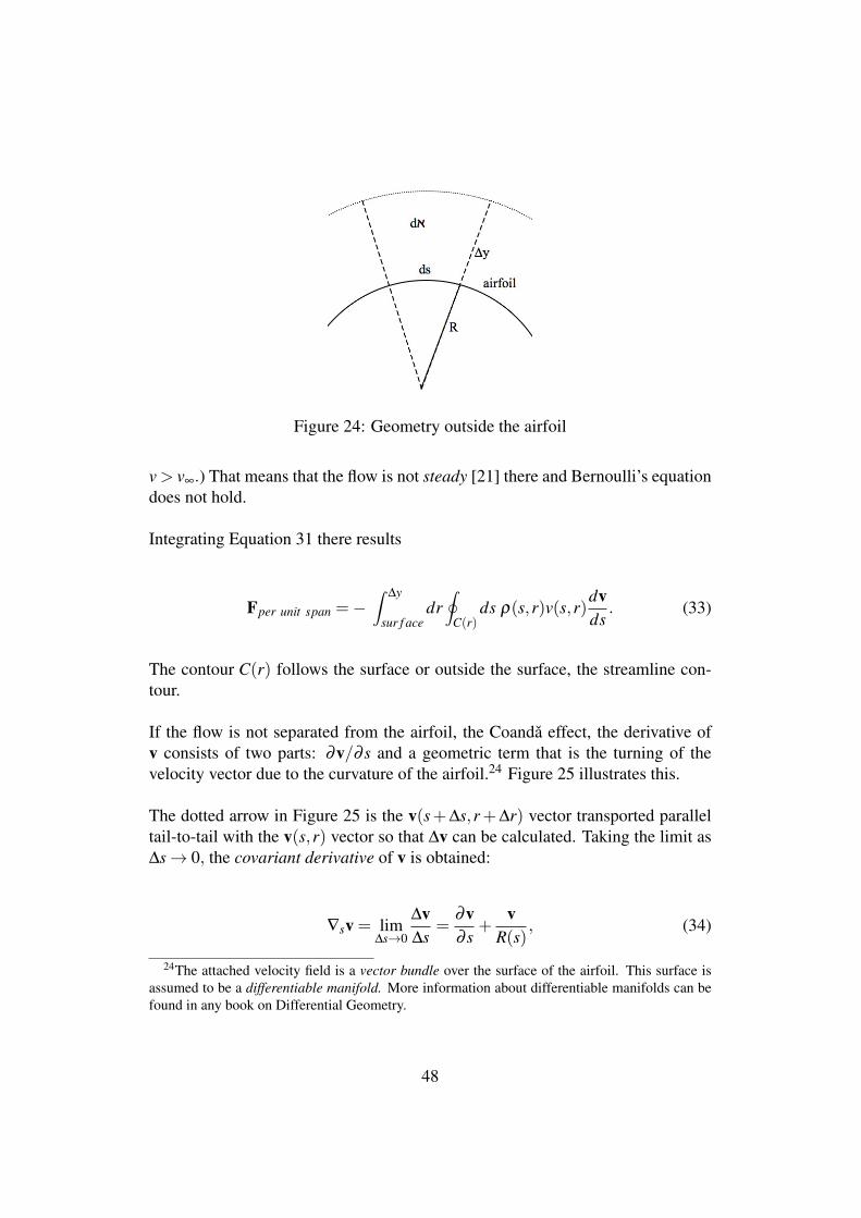
Figure 24: Geometry outside the airfoil
v > v∞.) That means that the flow is not steady [21] there and Bernoulli’s equationdoes not hold.
Integrating Equation 31 there results
Fper unit span =−∫
∆y
sur f acedr∮
C(r)ds ρ(s,r)v(s,r)
dvds
. (33)
The contour C(r) follows the surface or outside the surface, the streamline con-tour.
If the flow is not separated from the airfoil, the Coanda effect, the derivative ofv consists of two parts: ∂v/∂ s and a geometric term that is the turning of thevelocity vector due to the curvature of the airfoil.24 Figure 25 illustrates this.
The dotted arrow in Figure 25 is the v(s+∆s,r+∆r) vector transported paralleltail-to-tail with the v(s,r) vector so that ∆v can be calculated. Taking the limit as∆s→ 0, the covariant derivative of v is obtained:
∇sv = lim∆s→0
∆v∆s
=∂v∂ s
+v
R(s), (34)
24The attached velocity field is a vector bundle over the surface of the airfoil. This surface isassumed to be a differentiable manifold. More information about differentiable manifolds can befound in any book on Differential Geometry.
48
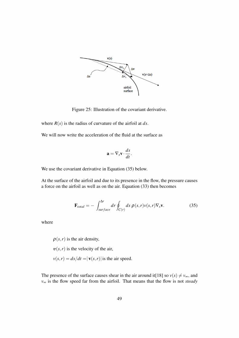
Figure 25: Illustration of the covariant derivative.
where R(s) is the radius of curvature of the airfoil at ds.
We will now write the acceleration of the fluid at the surface as
a = ∇sv ·dsdt
.
We use the covariant derivative in Equation (35) below.
At the surface of the airfoil and due to its presence in the flow, the pressure causesa force on the airfoil as well as on the air. Equation (33) then becomes
Ftotal =−∫
∆r
sur f acedr∮
C(r)ds ρ(s,r)v(s,r)∇sv. (35)
where
ρ(s,r) is the air density,
v(s,r) is the velocity of the air,
v(s,r) = ds/dt = v(s,r) is the air speed.
The presence of the surface causes shear in the air around it[18] so v(s) 6= v∞, andv∞ is the flow speed far from the airfoil. That means that the flow is not steady
49
[21] there and Bernoulli’s equation does not hold. This region is the boundarylayer and its thickness is δ .
Notice that the circulation,
Γ≡∮
F ·ds, (32)
doesn’t arise in this derivation. In its place we have Equation (2).25 We are lookingat the effect on the air flow of the complex behavior of the air at the surface and inthe boundary layer. This effect exists as a reaction to the lift force. Equation (35)replaces the Kutta-Joukowski theorem.
The difficulty is in evaluating the integrals in Equation (35). As has been notedabove, shear cannot be neglected. The pressure, even outside the boundary layer,is not constant. The boundary layer is defined as that space, thickness δ , justoutside the airfoil surface where
∂v(s,r)∂ r r = δ
' 0
and r is in the direction normal to the airfoil.
The behavior of the air in the boundary layer may be complex but for laminarflow over a non-stalling airfoil, its behavior results just in shear and a pressuregradient. The density, ρ, is actually a function both of s and r. What value shouldbe assigned ρ? We are concerned with the cause of lift, i.e., the forces on thesurface of the airfoil. Our understanding is in terms of Newton’s laws.26
Figure 26 is a drawing of an airfoil that causes bending of the flow. Notice thatthe bending is not just the deflection of the air by the lower surface of the airfoil.The flow along the top is bent also. The cause of the bending of the flow over the
25The circulation would be the first term in this equation, i.e. the integral of the forces normalto the airfoil. Notice that this integral is a mathematical object and does not indicate that there isa physical vortex around the airfoil. The resultant force on a buoyant object fixed in a quiescentfluid is written the same as the circulation integral except that the integral is over the surface of the3-dimensional object. In this case there is no flow at all.
26When Isaac Newton was asked why the apple falls as it does, he is reported to have replied:Hypothesis non fingo! That is, “I have no idea!” We don’t go any deeper than Newton’s laws.
50
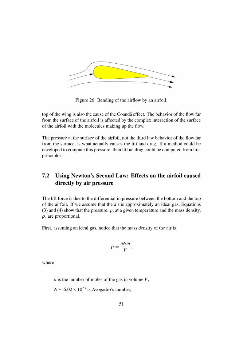
Figure 26: Bending of the airflow by an airfoil.
top of the wing is also the cause of the Coanda effect. The behavior of the flow farfrom the surface of the airfoil is affected by the complex interaction of the surfaceof the airfoil with the molecules making up the flow.
The pressure at the surface of the airfoil, not the third law behavior of the flow farfrom the surface, is what actually causes the lift and drag. If a method could bedeveloped to compute this pressure, then lift an drag could be computed from firstprinciples.
7.2 Using Newton’s Second Law: Effects on the airfoil causeddirectly by air pressure
The lift force is due to the differential in pressure between the bottom and the topof the airfoil. If we assume that the air is approximately an ideal gas, Equations(3) and (4) show that the pressure, p, at a given temperature and the mass density,ρ, are proportional.
First, assuming an ideal gas, notice that the mass density of the air is
ρ =nNm
V,
where
n is the number of moles of the gas in volume V ,
N ∼ 6.02×10²³ is Avogadro’s number,
51
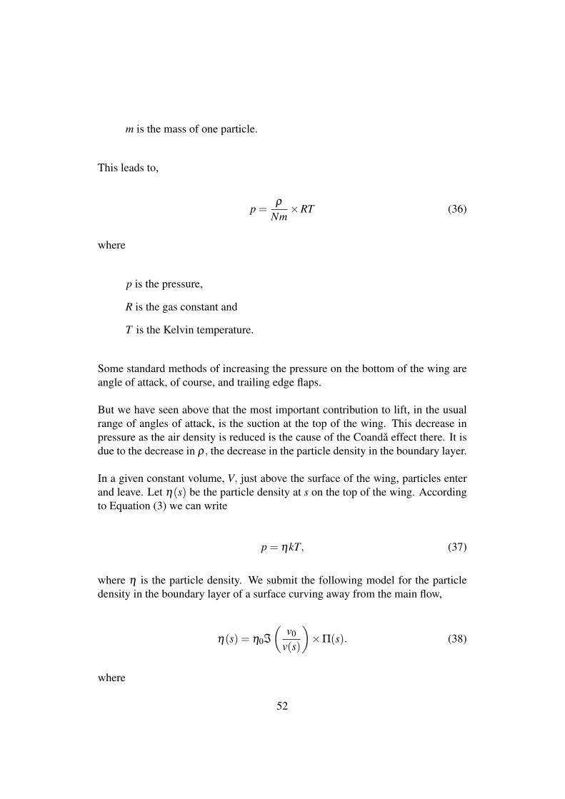
m is the mass of one particle.
This leads to,
p =ρ
Nm×RT (36)
where
p is the pressure,
R is the gas constant and
T is the Kelvin temperature.
Some standard methods of increasing the pressure on the bottom of the wing areangle of attack, of course, and trailing edge flaps.
But we have seen above that the most important contribution to lift, in the usualrange of angles of attack, is the suction at the top of the wing. This decrease inpressure as the air density is reduced is the cause of the Coanda effect there. It isdue to the decrease in ρ, the decrease in the particle density in the boundary layer.
In a given constant volume, V, just above the surface of the wing, particles enterand leave. Let η(s) be the particle density at s on the top of the wing. Accordingto Equation (3) we can write
p = ηkT, (37)
where η is the particle density. We submit the following model for the particledensity in the boundary layer of a surface curving away from the main flow,
η(s) = η0ℑ
(v0
v(s)
)×Π(s). (38)
where
52
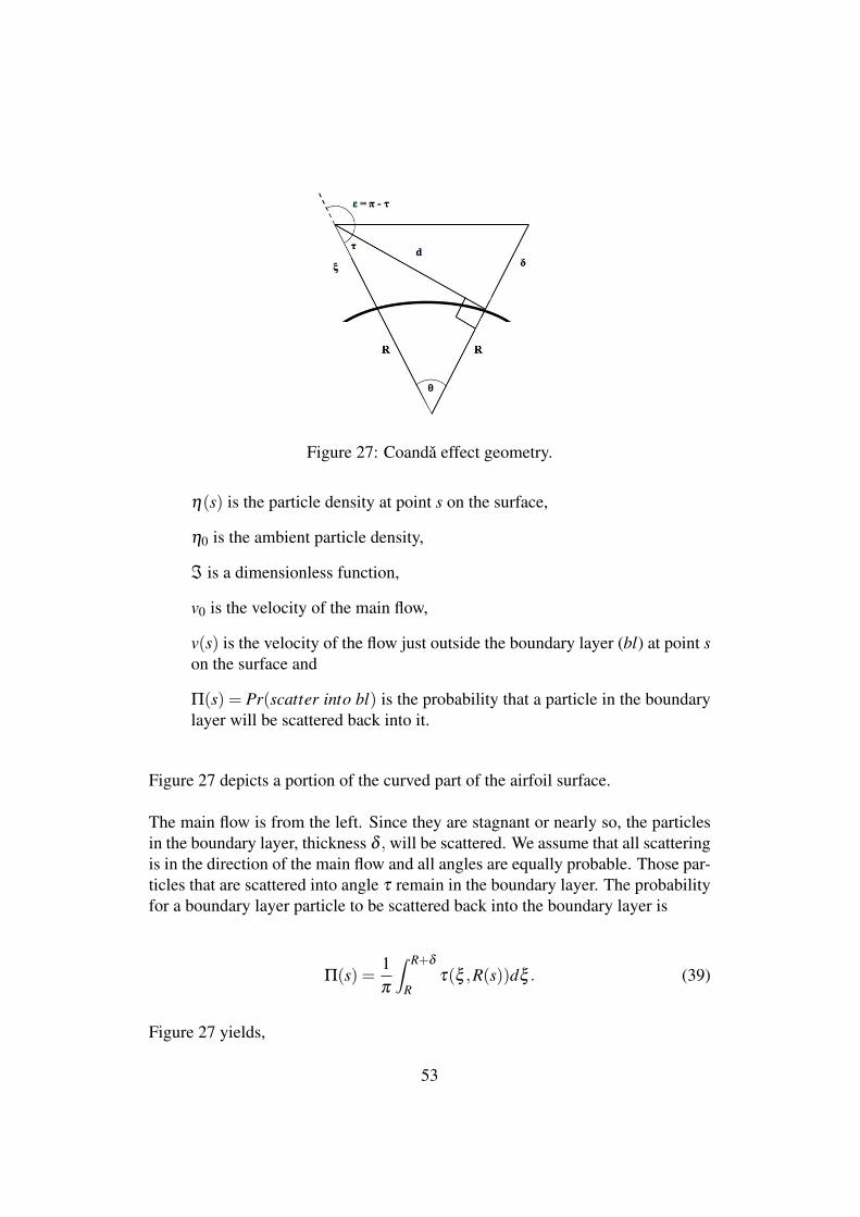
Figure 27: Coanda effect geometry.
η(s) is the particle density at point s on the surface,
η0 is the ambient particle density,
ℑ is a dimensionless function,
v0 is the velocity of the main flow,
v(s) is the velocity of the flow just outside the boundary layer (bl) at point son the surface and
Π(s) = Pr(scatter into bl) is the probability that a particle in the boundarylayer will be scattered back into it.
Figure 27 depicts a portion of the curved part of the airfoil surface.
The main flow is from the left. Since they are stagnant or nearly so, the particlesin the boundary layer, thickness δ , will be scattered. We assume that all scatteringis in the direction of the main flow and all angles are equally probable. Those par-ticles that are scattered into angle τ remain in the boundary layer. The probabilityfor a boundary layer particle to be scattered back into the boundary layer is
Π(s) =1π
∫ R+δ
Rτ(ξ ,R(s))dξ . (39)
Figure 27 yields,
53
τ(ξ ,R(s)) = sin−1[
RR+ξ
]. (40)
Combining Equations (37) through (40) there results
p(s) =η0kT
π×ℑ
(v0
v(s)
)∫ R+δ
Rsin−1
[R(s)
R+ξ
]dξ (41)
for the pressure on the top of the curved wing. At or near zero angle of attackthe pressure on the bottom of a flat wing is approximately ambient so the total liftforce acting on the wing is
Fdirect =η0kT
π
{S−
∫
↑
[ℑ
(v0
v(s)
)∫ R+δ
Rsin−1
[R(s)
R+ξ
]dξ
]ds}. (42)
where ↑ indicates the top surface of the wing and S is the area per unit span ofthe bottom surface. Since we consider the simple case of a flat bottom surfaceparallel to the flow, the force there is just the ambient pressure times the area. Thepressure on the upper surface, lowered by the action of the main flow shearingpast the curved surface, is responsible for most of the lift at zero angle of attack,Φ = 0.
Figure 4 in Section 4.2 hints that the flow, v(s), over the curved surface consistsmainly of boundary layer particles activated by interaction with the main flow.The function ℑ needs to be determined. Its form will have to do with the detailedstructure of the surface and the shape of the molecules of the flow.
8 Stalling wing
As the flow velocity increases, the secondary collisions that affect the flow par-ticles slowed by collisions with boundary layer particles cause the slowed flowparticles to be more violently knocked back toward the surface by the main flow.When they start to hit the surface itself, the forces on the surface there increase(see panel 3 in Figure 5). The wing is stalling. As the velocity increases still
54
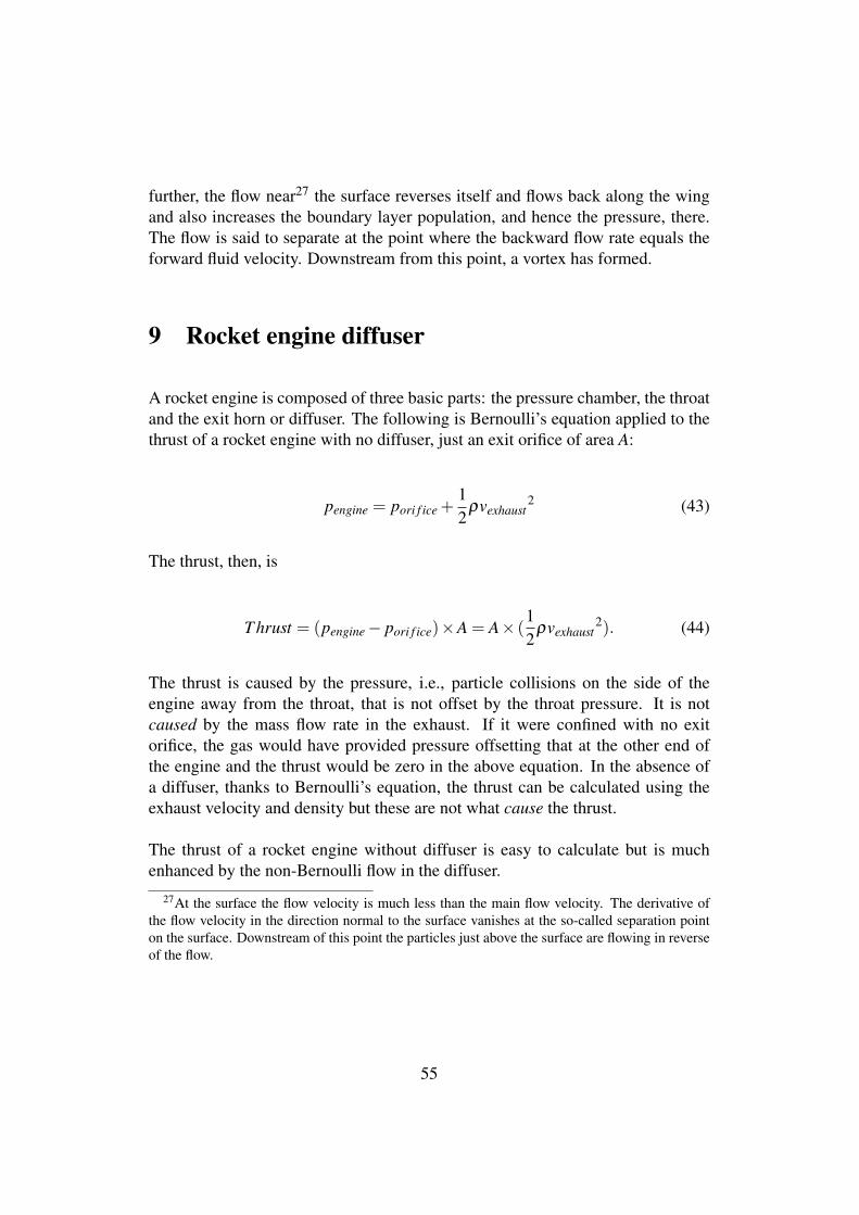
further, the flow near27 the surface reverses itself and flows back along the wingand also increases the boundary layer population, and hence the pressure, there.The flow is said to separate at the point where the backward flow rate equals theforward fluid velocity. Downstream from this point, a vortex has formed.
9 Rocket engine diffuser
A rocket engine is composed of three basic parts: the pressure chamber, the throatand the exit horn or diffuser. The following is Bernoulli’s equation applied to thethrust of a rocket engine with no diffuser, just an exit orifice of area A:
pengine = pori f ice +12
ρvexhaust2 (43)
The thrust, then, is
T hrust = (pengine− pori f ice)×A = A× (12
ρvexhaust2). (44)
The thrust is caused by the pressure, i.e., particle collisions on the side of theengine away from the throat, that is not offset by the throat pressure. It is notcaused by the mass flow rate in the exhaust. If it were confined with no exitorifice, the gas would have provided pressure offsetting that at the other end ofthe engine and the thrust would be zero in the above equation. In the absence ofa diffuser, thanks to Bernoulli’s equation, the thrust can be calculated using theexhaust velocity and density but these are not what cause the thrust.
The thrust of a rocket engine without diffuser is easy to calculate but is muchenhanced by the non-Bernoulli flow in the diffuser.
27At the surface the flow velocity is much less than the main flow velocity. The derivative ofthe flow velocity in the direction normal to the surface vanishes at the so-called separation pointon the surface. Downstream of this point the particles just above the surface are flowing in reverseof the flow.
55
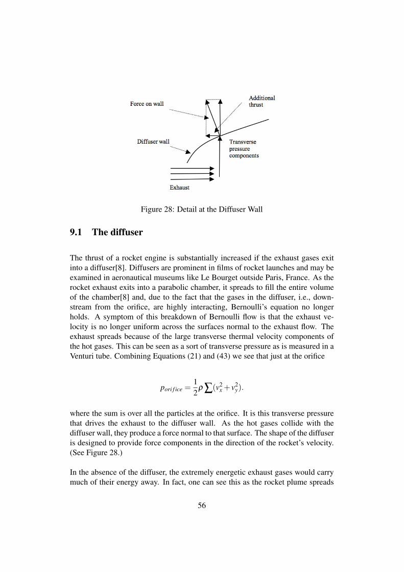
Figure 28: Detail at the Diffuser Wall
9.1 The diffuser
The thrust of a rocket engine is substantially increased if the exhaust gases exitinto a diffuser[8]. Diffusers are prominent in films of rocket launches and may beexamined in aeronautical museums like Le Bourget outside Paris, France. As therocket exhaust exits into a parabolic chamber, it spreads to fill the entire volumeof the chamber[8] and, due to the fact that the gases in the diffuser, i.e., down-stream from the orifice, are highly interacting, Bernoulli’s equation no longerholds. A symptom of this breakdown of Bernoulli flow is that the exhaust ve-locity is no longer uniform across the surfaces normal to the exhaust flow. Theexhaust spreads because of the large transverse thermal velocity components ofthe hot gases. This can be seen as a sort of transverse pressure as is measured in aVenturi tube. Combining Equations (21) and (43) we see that just at the orifice
pori f ice =12
ρ ∑(v2x + v2
y).
where the sum is over all the particles at the orifice. It is this transverse pressurethat drives the exhaust to the diffuser wall. As the hot gases collide with thediffuser wall, they produce a force normal to that surface. The shape of the diffuseris designed to provide force components in the direction of the rocket’s velocity.(See Figure 28.)
In the absence of the diffuser, the extremely energetic exhaust gases would carrymuch of their energy away. In fact, one can see this as the rocket plume spreads
56

beyond the diffuser at high altitude in a sort of umbrella shape. The diffuser, then,extracts work from the gases before they exit beyond the rocket. The analogoussituation in an internal combustion engine is to delay the opening of the exhaustvalves in order to extract more work from the hot gas in the combustion chamber.
An interesting feature of some diffusers, like those of the French Ariane rocket,is a sort of rifling on the diffuser wall. This rifling causes the gases to swirl, thusincreasing the path length for the exiting particles. This keeps them in contact withthe wall longer allowing more of their heat energy to be converted into thrust.
10 The high-bypass turbofan jet engine
By the 1950s the turbojet had largely replaced the piston engine driven propeller asthe main means of aircraft propulsion. The advance in the design of heat-seekingmissiles, however, was becoming a serious threat to military aircraft due to thehigh temperature of the jet exhaust. The thought occurred to engine designersthat a sheath of cooler air would mask the heat signature of the jet exhaust so theheat-seeking missiles could could not “see” it. This bypassing air, however, didnot only shield the exhaust but it increased dramatically the overall efficiency ofthe jet engine in subsonic flight. Thus was born a true breakthrough in jet enginedesign, a very useful spin-off of technology originally intended only for militaryuse.
Before the development of the modern high-bypass turbofan28 jet engine, the rimof the entrance to the engine cowl was rather sharp. (See Figure 29.)
Modern turbofans (Figure 30) have a gently curved entrance duct. This may seemtrivial but it has the effect of greatly increasing the entrance aperture for the tur-bofan due to the Coanda effect. This cowl creates a bow wave as it moves throughthe air. The presence this bow wave at subsonic speeds29 creates a flow patternthat precedes the aircraft. Examination of the third panel of Figure 5 shows howthe presence of a curved surface in an air flow causes what might be called Coandaentrainment of air from outside. This entrainment compresses the air in front of
28In high-bypass turbofan engines, most of the air entering the intake cowl bypasses the the jetengine itself. This air is compressed somewhat by the shape of the entry cowl and its attendantbow-wave. The compressed air is propelled by a fan driven by a conventional turbojet engine andthen exits the cowl in an annulus at the rear.
29At supersonic speeds this effect disappears because the aircraft has outrun its bow wave.
57
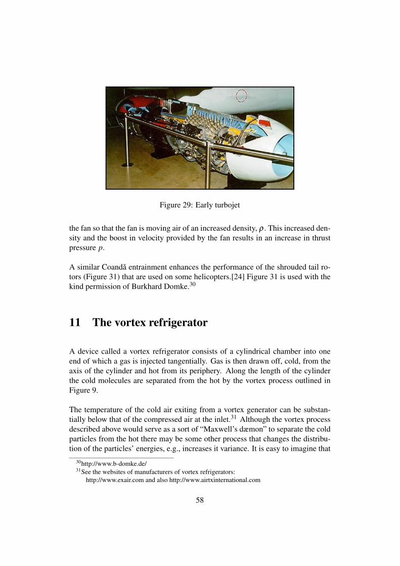
Figure 29: Early turbojet
the fan so that the fan is moving air of an increased density, ρ. This increased den-sity and the boost in velocity provided by the fan results in an increase in thrustpressure p.
A similar Coanda entrainment enhances the performance of the shrouded tail ro-tors (Figure 31) that are used on some helicopters.[24] Figure 31 is used with thekind permission of Burkhard Domke.30
11 The vortex refrigerator
A device called a vortex refrigerator consists of a cylindrical chamber into oneend of which a gas is injected tangentially. Gas is then drawn off, cold, from theaxis of the cylinder and hot from its periphery. Along the length of the cylinderthe cold molecules are separated from the hot by the vortex process outlined inFigure 9.
The temperature of the cold air exiting from a vortex generator can be substan-tially below that of the compressed air at the inlet.31 Although the vortex processdescribed above would serve as a sort of “Maxwell’s dæmon” to separate the coldparticles from the hot there may be some other process that changes the distribu-tion of the particles’ energies, e.g., increases it variance. It is easy to imagine that
30http://www.b-domke.de/31See the websites of manufacturers of vortex refrigerators:
http://www.exair.com and also http://www.airtxinternational.com
58
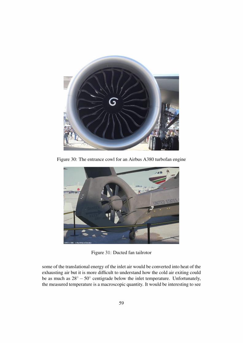
Figure 30: The entrance cowl for an Airbus A380 turbofan engine
Figure 31: Ducted fan tailrotor
some of the translational energy of the inlet air would be converted into heat of theexhausting air but it is more difficult to understand how the cold air exiting couldbe as much as 28◦− 50◦ centigrade below the inlet temperature. Unfortunately,the measured temperature is a macroscopic quantity. It would be interesting to see
59
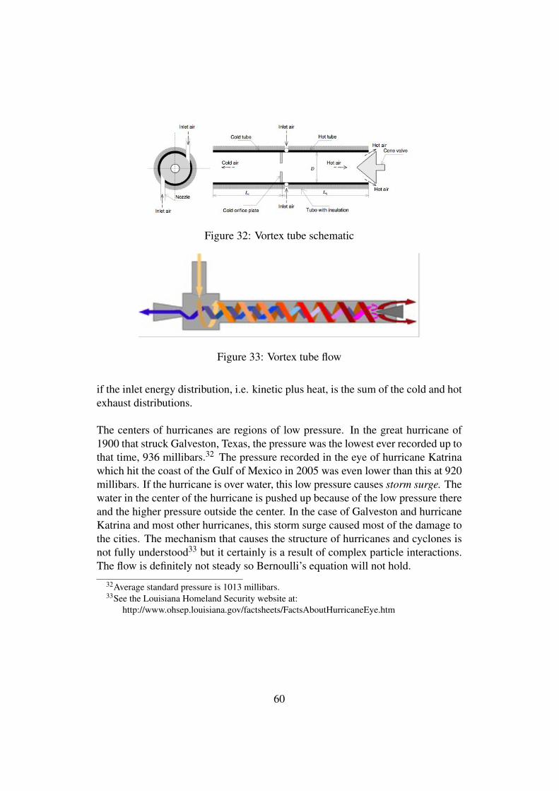
Figure 32: Vortex tube schematic
Figure 33: Vortex tube flow
if the inlet energy distribution, i.e. kinetic plus heat, is the sum of the cold and hotexhaust distributions.
The centers of hurricanes are regions of low pressure. In the great hurricane of1900 that struck Galveston, Texas, the pressure was the lowest ever recorded up tothat time, 936 millibars.32 The pressure recorded in the eye of hurricane Katrinawhich hit the coast of the Gulf of Mexico in 2005 was even lower than this at 920millibars. If the hurricane is over water, this low pressure causes storm surge. Thewater in the center of the hurricane is pushed up because of the low pressure thereand the higher pressure outside the center. In the case of Galveston and hurricaneKatrina and most other hurricanes, this storm surge caused most of the damage tothe cities. The mechanism that causes the structure of hurricanes and cyclones isnot fully understood33 but it certainly is a result of complex particle interactions.The flow is definitely not steady so Bernoulli’s equation will not hold.
32Average standard pressure is 1013 millibars.33See the Louisiana Homeland Security website at:
http://www.ohsep.louisiana.gov/factsheets/FactsAboutHurricaneEye.htm
60
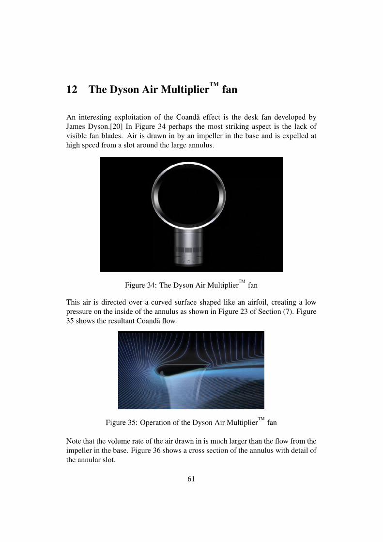
12 The Dyson Air MultiplierTM fan
An interesting exploitation of the Coanda effect is the desk fan developed byJames Dyson.[20] In Figure 34 perhaps the most striking aspect is the lack ofvisible fan blades. Air is drawn in by an impeller in the base and is expelled athigh speed from a slot around the large annulus.
Figure 34: The Dyson Air MultiplierTM
fan
This air is directed over a curved surface shaped like an airfoil, creating a lowpressure on the inside of the annulus as shown in Figure 23 of Section (7). Figure35 shows the resultant Coanda flow.
Figure 35: Operation of the Dyson Air MultiplierTM
fan
Note that the volume rate of the air drawn in is much larger than the flow from theimpeller in the base. Figure 36 shows a cross section of the annulus with detail ofthe annular slot.
61
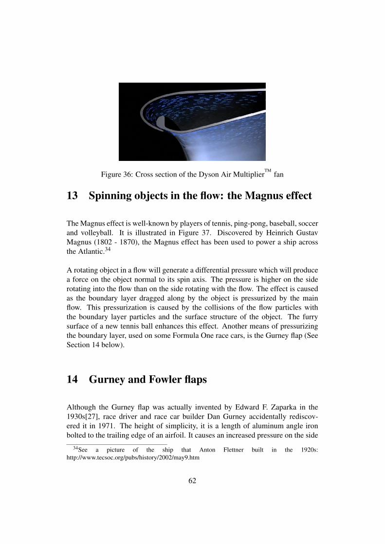
Figure 36: Cross section of the Dyson Air MultiplierTM
fan
13 Spinning objects in the flow: the Magnus effect
The Magnus effect is well-known by players of tennis, ping-pong, baseball, soccerand volleyball. It is illustrated in Figure 37. Discovered by Heinrich GustavMagnus (1802 - 1870), the Magnus effect has been used to power a ship acrossthe Atlantic.34
A rotating object in a flow will generate a differential pressure which will producea force on the object normal to its spin axis. The pressure is higher on the siderotating into the flow than on the side rotating with the flow. The effect is causedas the boundary layer dragged along by the object is pressurized by the mainflow. This pressurization is caused by the collisions of the flow particles withthe boundary layer particles and the surface structure of the object. The furrysurface of a new tennis ball enhances this effect. Another means of pressurizingthe boundary layer, used on some Formula One race cars, is the Gurney flap (SeeSection 14 below).
14 Gurney and Fowler flaps
Although the Gurney flap was actually invented by Edward F. Zaparka in the1930s[27], race driver and race car builder Dan Gurney accidentally rediscov-ered it in 1971. The height of simplicity, it is a length of aluminum angle ironbolted to the trailing edge of an airfoil. It causes an increased pressure on the side
34See a picture of the ship that Anton Flettner built in the 1920s:http://www.tecsoc.org/pubs/history/2002/may9.htm
62
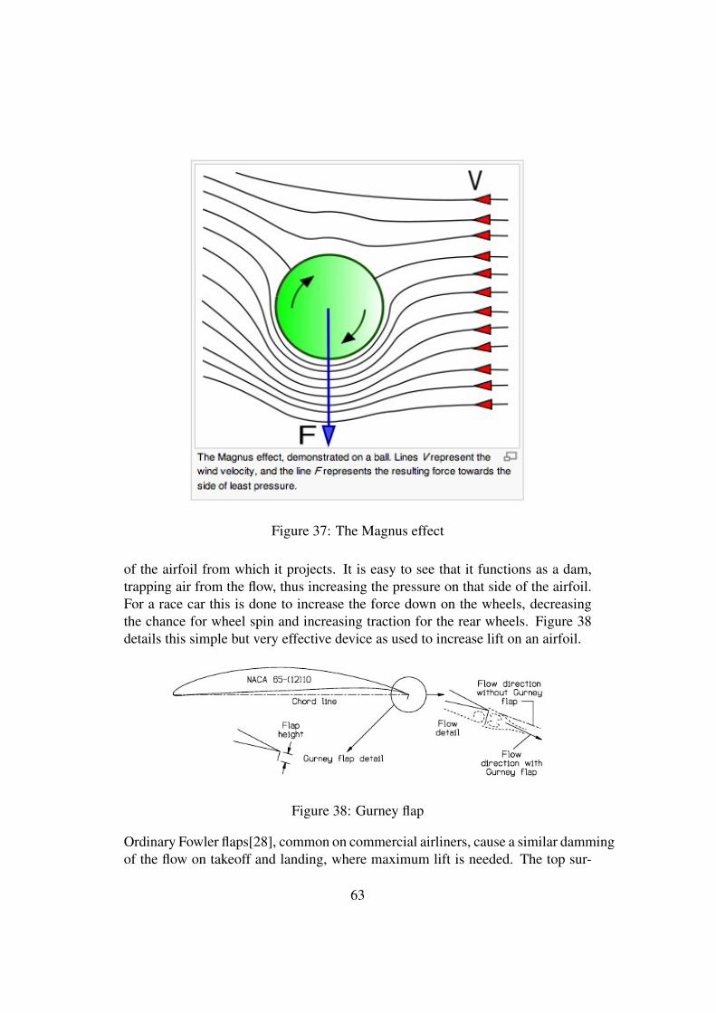
Figure 37: The Magnus effect
of the airfoil from which it projects. It is easy to see that it functions as a dam,trapping air from the flow, thus increasing the pressure on that side of the airfoil.For a race car this is done to increase the force down on the wheels, decreasingthe chance for wheel spin and increasing traction for the rear wheels. Figure 38details this simple but very effective device as used to increase lift on an airfoil.
Figure 38: Gurney flap
Ordinary Fowler flaps[28], common on commercial airliners, cause a similar dammingof the flow on takeoff and landing, where maximum lift is needed. The top sur-
63
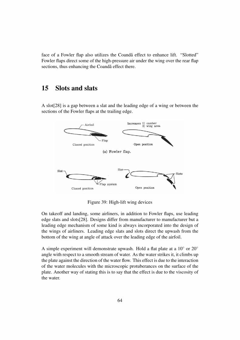
face of a Fowler flap also utilizes the Coanda effect to enhance lift. “Slotted”Fowler flaps direct some of the high-pressure air under the wing over the rear flapsections, thus enhancing the Coanda effect there.
15 Slots and slats
A slot[28] is a gap between a slat and the leading edge of a wing or between thesections of the Fowler flaps at the trailing edge.
Figure 39: High-lift wing devices
On takeoff and landing, some airliners, in addition to Fowler flaps, use leadingedge slats and slots[28]. Designs differ from manufacturer to manufacturer but aleading edge mechanism of some kind is always incorporated into the design ofthe wings of airliners. Leading edge slats and slots direct the upwash from thebottom of the wing at angle of attack over the leading edge of the airfoil.
A simple experiment will demonstrate upwash. Hold a flat plate at a 10◦ or 20◦
angle with respect to a smooth stream of water. As the water strikes it, it climbs upthe plate against the direction of the water flow. This effect is due to the interactionof the water molecules with the microscopic protuberances on the surface of theplate. Another way of stating this is to say that the effect is due to the viscosity ofthe water.
64
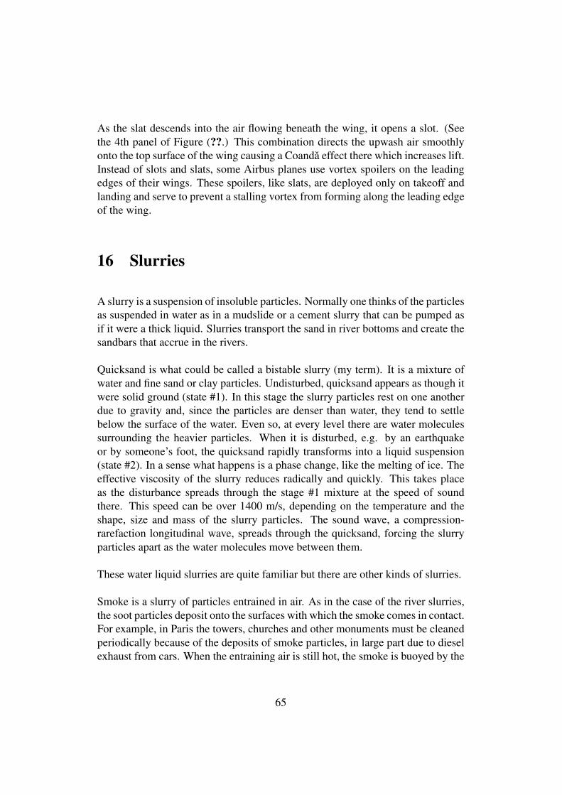
As the slat descends into the air flowing beneath the wing, it opens a slot. (Seethe 4th panel of Figure (??.) This combination directs the upwash air smoothlyonto the top surface of the wing causing a Coanda effect there which increases lift.Instead of slots and slats, some Airbus planes use vortex spoilers on the leadingedges of their wings. These spoilers, like slats, are deployed only on takeoff andlanding and serve to prevent a stalling vortex from forming along the leading edgeof the wing.
16 Slurries
A slurry is a suspension of insoluble particles. Normally one thinks of the particlesas suspended in water as in a mudslide or a cement slurry that can be pumped asif it were a thick liquid. Slurries transport the sand in river bottoms and create thesandbars that accrue in the rivers.
Quicksand is what could be called a bistable slurry (my term). It is a mixture ofwater and fine sand or clay particles. Undisturbed, quicksand appears as though itwere solid ground (state #1). In this stage the slurry particles rest on one anotherdue to gravity and, since the particles are denser than water, they tend to settlebelow the surface of the water. Even so, at every level there are water moleculessurrounding the heavier particles. When it is disturbed, e.g. by an earthquakeor by someone’s foot, the quicksand rapidly transforms into a liquid suspension(state #2). In a sense what happens is a phase change, like the melting of ice. Theeffective viscosity of the slurry reduces radically and quickly. This takes placeas the disturbance spreads through the stage #1 mixture at the speed of soundthere. This speed can be over 1400 m/s, depending on the temperature and theshape, size and mass of the slurry particles. The sound wave, a compression-rarefaction longitudinal wave, spreads through the quicksand, forcing the slurryparticles apart as the water molecules move between them.
These water liquid slurries are quite familiar but there are other kinds of slurries.
Smoke is a slurry of particles entrained in air. As in the case of the river slurries,the soot particles deposit onto the surfaces with which the smoke comes in contact.For example, in Paris the towers, churches and other monuments must be cleanedperiodically because of the deposits of smoke particles, in large part due to dieselexhaust from cars. When the entraining air is still hot, the smoke is buoyed by the
65
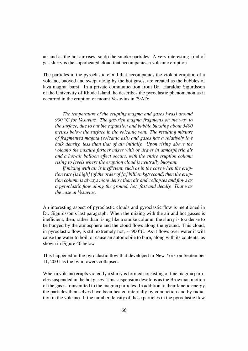
air and as the hot air rises, so do the smoke particles. A very interesting kind ofgas slurry is the superheated cloud that accompanies a volcanic eruption.
The particles in the pyroclastic cloud that accompanies the violent eruption of avolcano, buoyed and swept along by the hot gases, are created as the bubbles oflava magma burst. In a private communication from Dr. Haraldur Sigurdssonof the University of Rhode Island, he describes the pyroclastic phenomenon as itoccurred in the eruption of mount Vesuvius in 79AD:
The temperature of the erupting magma and gases [was] around900 ◦C for Vesuvius. The gas-rich magma fragments on the way tothe surface, due to bubble expansion and bubble bursting about 5400metres below the surface in the volcanic vent. The resulting mixtureof fragmented magma (volcanic ash) and gases has a relatively lowbulk density, less than that of air initially. Upon rising above thevolcano the mixture further mixes with or draws in atmospheric airand a hot-air balloon effect occurs, with the entire eruption columnrising to levels where the eruption cloud is neutrally buoyant.
If mixing with air is inefficient, such as in the case when the erup-tion rate [is high] (of the order of [a] billion kg/second) then the erup-tion column is always more dense than air and collapses and flows asa pyroclastic flow along the ground, hot, fast and deadly. That wasthe case at Vesuvius.
An interesting aspect of pyroclastic clouds and pyroclastic flow is mentioned inDr. Sigurdsson’s last paragraph. When the mixing with the air and hot gasses isinefficient, then, rather than rising like a smoke column, the slurry is too dense tobe buoyed by the atmosphere and the cloud flows along the ground. This cloud,in pyroclastic flow, is still extremely hot, ∼ 900◦C. As it flows over water it willcause the water to boil, or cause an automobile to burn, along with its contents, asshown in Figure 40 below.
This happened in the pyroclastic flow that developed in New York on September11, 2001 as the twin towers collapsed.
When a volcano erupts violently a slurry is formed consisting of fine magma parti-cles suspended in the hot gases. This suspension develops as the Brownian motionof the gas is transmitted to the magma particles. In addition to their kinetic energythe particles themselves have been heated internally by conduction and by radia-tion in the volcano. If the number density of these particles in the pyroclastic flow
66
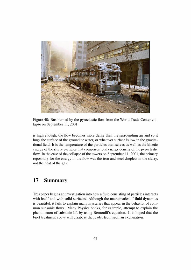
Figure 40: Bus burned by the pyroclastic flow from the World Trade Center col-lapse on September 11, 2001.
is high enough, the flow becomes more dense than the surrounding air and so ithugs the surface of the ground or water, or whatever surface is low in the gravita-tional field. It is the temperature of the particles themselves as well as the kineticenergy of the slurry particles that comprises total energy density of the pyroclasticflow. In the case of the collapse of the towers on September 11, 2001, the primaryrepository for the energy in the flow was the iron and steel droplets in the slurry,not the heat of the gas.
17 Summary
This paper begins an investigation into how a fluid consisting of particles interactswith itself and with solid surfaces. Although the mathematics of fluid dynamicsis beautiful, it fails to explain many mysteries that appear in the behavior of com-mon subsonic flows. Many Physics books, for example, attempt to explain thephenomenon of subsonic lift by using Bernoulli’s equation. It is hoped that thebrief treatment above will disabuse the reader from such an explanation.
67
18 Conclusion
Anyone who has contemplated ocean waves in their magnificence or watched soli-tons marching upstream in channel flow cannot but be amazed at the beauty ex-hibited by the behavior of fluids, this in spite of difficulties that defy our ability tocalculate their detailed behavior. It is said that the first stage of understanding aphenomenon is that of its careful observation. Perhaps the next is to attempt to for-mulate the behavior of the constituents of the phenomenon. Prior to the turn of the19th century, it was believed that fluids were fundamental entities, i.e., not com-posed of anything. Since Einstein’s 1905 paper on Brownian motion, however, ithas been clear that fluids are composed of molecules. To assume, then, at leastfor the sake of investigation, that all fluid behavior is caused by the interactions ofthese molecules and those of solid surfaces immersed in the fluid, seems natural.These assumptions are useful even in the absence of a tractable mathematics to de-scribe behavior at this level. The current mathematical approaches, including theNavier-Stokes equations, make the fluid approximation[21] fundamental. Someof the most baffling behavior of fluids, however, takes place in regimes where thefluid approximation is not valid.
Perhaps, as computers become faster and with more and more memory, some ofthese behaviors will succumb to calculation. In the meantime we observe andcontemplate and we are amazed.
References
[1] See http://www.tfcbooks.com/articles/tdt7.htm for information on NicolaTesla.
[2] An interesting treatment of the pitfalls in confusing fluids and aggregatesof particles is found in: Woods, L. C. The Influence of the Philosophy ofScience on Research. Lecture given at the Auckland Institute of Technology.(1998.) See Appendix A for this lecture in full.
[3] For readers not acquainted with Ludwig Boltzmann,See http://www-groups.dcs.st-and.ac.uk/∼history/Mathematicians/Boltzmann.htmlor any of many references to his work in Statistical Mechanics.
[4] See http://en.wikipedia.org/wiki/Joule−Thomson_effect
68
[5] Subsonic aerodynamics and performance of a smart vortex generator sys-tem. Barrett, Ron, Auburn Univ., AL; Farokhi, Saeed, Kansas, Univ.,Lawrence Journal of Aircraft 1996. 0021-8669 vol.33 no.2 (393-398). doi:10.2514/3.46950
[6] http://www.paulnoll.com/Oregon/Birds/flight-slow-flapping-diagram.htmlandhttp://www.metacafe.com/watch/2167886/birds_in_slow_motion_a_short/
[7] Collected Papers of Albert Einstein, vol. 2
[8] Schlichting, H. and K. Gersten, Boundary Layer Theory (8th ed.) Springer:Berlin. (2000.)
[9] The “Coanda Effect”, Report No. 327, Office of the Publication Board, De-partment of Commerce, Washington, DC (1944.)
[10] http://en.wikipedia.org/wiki/Kutta-Joukowski_theorem#Formal_derivation
[11] http://www.physics.thetangentbundle.net/wiki/Fluid_mechanics/Kutta-Joukowski_theorem
[12] USP 2,108,652 Propelling Device. See Appendix B.
[13] Denker, John S. http://www.av8n.com/how/htm/airfoils.html section 3.5
[14] See the website of Professor Martin Hepperle: http://www.mh-aerotools.de/airfoils/index.htm
[15] Anderson, John D. Jr. Introduction to Flight (3rd ed.) McGraw-Hill:NewYork. (1989.)
[16] http://en.wikipedia.org/wiki/Potential_flow#Applicability_and_limitations
[17] Hoffman, Johan and Claes Johnson. Computational Turbulent Incompress-ible Flow. Applied Mathematics: Body and Soul 4. Springer. (2007.) ISBN:978-3-540-46531-7.
[18] Colombini, Marco. University of Genoa, Italyhttp://www.av8n.com/irro/profilo4_e.html
[19] Vortex coolers are available for sale.See http://www.newmantools.com/vortec/nema4.htmfor an assortment.
69
[20] http://www.dysonairmultiplier.com/
[21] Landau, L. D. and E. M. Lifshitz Fluid Dynamics (2nd ed.) (Volume 6:Course of Theoretical Physics) U.K. Pergamon. (1984.)
[22] http://www.aerospaceweb.org/question/planes/q0176.shtml
[23] H. Riedel, ”Grundzüge der Strömungsforgänge beim Anlegen und Abreißeneines Flachstrahls bei der Umströmung eines Flügelprofils (Coanda-Effekt)”Deutsche Luft- und Raumfahrt Forschungsbericht 71-46 (1971.)
[24] Aerodynamic Performance Analysis of a Helicopter Shrouded Tail Rotor Us-ing an Unstructured Mesh Flow Solver, Lee, H. D., O. J. Kwon, and J. Joo.The 5th Asian Computational Fluid Dynamics [Conference], Busan, Korea,(October 27 - 30, 2003.)
[25] Working Model allows the programming of 2D kinematic models. Seehttp://www.design-simulation.com/
[26] Senior thesis of Jacob Vianni, University of California, Santa Cruz. (2006.)
[27] See the interesting article:http://www.allamericanracers.com/gurney_flap.html
[28] See http://www.centennialofflight.gov/essay/Theories_of_Flight/Devices/TH17G5.htm
70
A On the consideration of fluids at the particle level
71
The Influence of the Philosophyof Science on Research
L.C. Woods
(Balliol College, University of Oxford)
Lecture delivered at the Auckland Institute of Technologyon Friday, 7th August, 1998.
1
1. Introduction
When I was young, I read an article that claimed that the purpose ofscientific theory was to describe phenomena rather than to explain it. Thissurprised and disappointed me. Apparently we could achieve no more thanan empirical account of the real world, and could not expect to understandit. This conservative philosophy is known as instrumentalism, because itmaintains that a theory is no more than an ‘instrument’ for making predic-tions. The opposing view is that theories relate to underlying mechanismsand that these are responsible for the observed phenomena. To know themechanism is to understand the phenomenon. However this realist philoso-phy usually depends on some metaphysical elements, introduced to enlargethe fabric of the hidden world and thus to aid explanation. And it was theliberal introduction of such unobservable elements that added force to theinstrumentalist position, an extreme form of which is known as positivism.This holds that all statements other than those describing or predicting ob-servations are meaningless (including this statement?). Knowledge is onlywhat can be verified directly. Logical positivism augments positivism byadmitting mathematical entities logically connected to observations, evenif they are not directly measurable.
An alternative title for this talk would be ‘The legacy of Logical Posi-tivism’. This philosophy was greatly boosted in the first half of this centuryby the difficulty of giving the formalism of quantum mechanics an objectiveand realist interpretation. Hidden variables of one sort or another, evenincluding parallel universes, have been advanced as possible solutions. Butthe experts have not been convinced. That debate continues and I expectthat it will ultimately be resolved in favour of a realistic explanation ratherthan an instrumentalist description. In any case this unresolved difficultywith realism at the smallest scales does not justify our rejecting it at thedeterministic mesoscopic and macroscopic scales. What I shall illustrate isthe way in which some scientists’ preference for mathematical descriptionover physical explanation has led to important differences in the way theyhave pursued their research. Fields that are particularly vulnerable to thelegacy of positivism are thermodynamics and plasma physics. Very oftenthe researchers are unaware that they are labouring under the influence ofa largely discredited philosophy.
2. Some Philosophical Background
By a ‘mechanism’ I mean the representation of a real process in termsinvolving familiar physical actions, e.g. we might say that the thermo-electric transport of heat is due to the fact that higher energy electronshave a smaller probability of colliding with ions than those of lower energy,or that a solar prominence is supported high in the corona by magnetic
2
forces. Once we have the mechanism identified, fitting it out with suitablemathematics is often the easier task. In specifying a mechanism, the firstobjective is to try to identify those features essential to the phenomenonunder consideration. Elaboration of the model can follow when the min-imalist position has proved itself. But it may be necessary to add someunobservable structure to the mechanism from the outset, e.g. the mag-netic field lying out-of-sight well below the photosphere when modelling asunspot structure.
Ockham was a 14th-century, Scholastic philosopher, who attacked thesupremacy of Papal power. His ‘razor’ was the statement that entitiesare not to be multiplied beyond necessity. In a similar vein, Ernst Mach(1838–1916) stated that ‘it is the aim of science to present the facts ofnature in the simplest and most economic conceptual formulations’. Thiswas a reaction against the metaphysical extravagances of the 17th and 18thcenturies, during which, inter alia, various fluids were adduced to ‘explain’physical phenomena. A classical case was the chemists’ phlogiston that,having negative weight, supposedly explained the increase in mass due toburning—the heat drove off the phlogiston. Oxygen was yet to be discov-ered. Heat had the properties of an indestructible fluid called ‘caloric’;electricity was said to be composed of two fluids, with no more evidencethan this seemed to provide an explanation of some observations. Butnowadays we do talk of electron and ion fluids. Also Carnot managed toestablish the principle that later evolved into the second law of thermody-namics, by employing the caloric concept. (It was the first law that laterdestroyed the conservation of caloric.) So some metaphysical inventionsprove to be closer to the truth than at first imagined. Such elements evolvefrom being metaphysical to eventually being considered to be ‘real’.
Atoms were ruled out by Mach and other anti-atomists of his day. Theycould not be observed, so were not real. They could be admitted only asa device to give economy of thought. Realists are much bolder, willing tointroduce unobserved elements and to take them as being real, in order toprovide ‘explanations’. A classic example is William Harvey’s (1578-1657)explanation of the circulation of the blood and the function of the heartas a pump. Although he had no microscope to see the capillary vesselsconnecting the arterial and venous systems, he maintained from evidenceimplying a circulation that they must exist. Pauli’s (1930) invention ofthe neutrino to ensure the conservation of energy and momentum duringbeta decay is another good example of a bold metaphysical creation. Itwas not until powerful nuclear reactors were available that the existence ofneutrinos could be confirmed.
Analogy is a powerful, heuristic means of arriving at a possible descrip-tion of a new phenomenon. It may be a mathematical likeness only, as withthe fact that the temperature in steady-state heat flux and the gravitationpotential both satisfy Laplace’s equation, or it can be a deeper physical
3
analogy, such as that between the transport of heat by colliding particlesand its transport by photons within the Sun. For example Einstein’s inter-pretation of Brownian motion as being due to the uneven bombardment ofmicroscopic particles by molecules may have taken root in his mind froman obvious macroscopic analogy, and its success led quickly to the full ac-ceptance of the reality of molecules. Metaphysical inventions have a centralrole in science, provided one always remembers that they are on ‘trial’ untilthe indirect evidence is so strong that they can be considered to be ‘real’.
Maxwell was pre-eminent in his use of analogy. He deployed it in twofamous examples. First in his kinetic theory of gases he used a ‘billiard-ball’ model to describe the trajectories of the molecules. This was excellentfor monatomic molecules, but partially failed with diatomic molecules forreasons that are now obvious to us. His other great analogy was to representmagnetic fields as vortex filaments in a ‘fluid’, and to separate them byparticles each revolving on its own axis in the opposite direction from thatof the vortices. These ‘idle-wheels’ (later identified as ‘electrons’) were toallow the free rotation of the vortex filaments. To cap it all, he gave thevortices elastic properties to represent the displacement current! In thismanner he arrived at his set of equations for the electromagnetic field. Hefound that the velocity with which disturbances propagated through hissystem of vortices and particles (70,843 leagues per sec.) agreed so closelywith Fizeau’s value for the speed of light that he remarked “we can scarcelyavoid the inference that light consists in the transverse modulations of thesame medium which is the cause of electric and magnetic phenomena”.
Then the mechanical description was abandoned, it being assumed thatthe equations alone now represented the phenomenon. Maxwell’s analogy,however absurd it seems today, led him to the greatest discovery of the19th century, namely that light was electromagnetic in nature. The Frenchpositivist, Pierre Duhem, observed sarcastically that Maxwell had cheatedby falsifying one of the equations of elasticity in order to obtain a resultthat he already knew by other means.
However if one asserts the whole theory is simply the equations, oneis adopting a positivist point of view. It is Faraday’s great metaphysicalconstruction—the notion of an electromagnetic field permeating space—that allows a return to a physical description of Maxwell’s equations. Thiscontinuum picture is very helpful in trying to understand the interaction offields and particles. I shall use ‘mechanism’ in this extended sense in whatfollows.
Since logical positivists eschew physical mechanisms, they are attractedto mathematical treatments, especially when an axiomatic basis can beadopted or devised to give the approach the gloss of pure mathematics.The belief that, excepting blunders, mathematical proofs are absolutelycertain and therefore superior to physical arguments, should have beendealt the coup de grace by Godel’s incompleteness theorem. This states
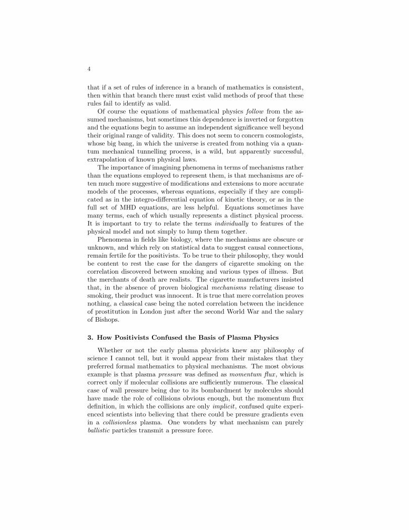
4
that if a set of rules of inference in a branch of mathematics is consistent,then within that branch there must exist valid methods of proof that theserules fail to identify as valid.
Of course the equations of mathematical physics follow from the as-sumed mechanisms, but sometimes this dependence is inverted or forgottenand the equations begin to assume an independent significance well beyondtheir original range of validity. This does not seem to concern cosmologists,whose big bang, in which the universe is created from nothing via a quan-tum mechanical tunnelling process, is a wild, but apparently successful,extrapolation of known physical laws.
The importance of imagining phenomena in terms of mechanisms ratherthan the equations employed to represent them, is that mechanisms are of-ten much more suggestive of modifications and extensions to more accuratemodels of the processes, whereas equations, especially if they are compli-cated as in the integro-differential equation of kinetic theory, or as in thefull set of MHD equations, are less helpful. Equations sometimes havemany terms, each of which usually represents a distinct physical process.It is important to try to relate the terms individually to features of thephysical model and not simply to lump them together.
Phenomena in fields like biology, where the mechanisms are obscure orunknown, and which rely on statistical data to suggest causal connections,remain fertile for the positivists. To be true to their philosophy, they wouldbe content to rest the case for the dangers of cigarette smoking on thecorrelation discovered between smoking and various types of illness. Butthe merchants of death are realists. The cigarette manufacturers insistedthat, in the absence of proven biological mechanisms relating disease tosmoking, their product was innocent. It is true that mere correlation provesnothing, a classical case being the noted correlation between the incidenceof prostitution in London just after the second World War and the salaryof Bishops.
3. How Positivists Confused the Basis of Plasma Physics
Whether or not the early plasma physicists knew any philosophy ofscience I cannot tell, but it would appear from their mistakes that theypreferred formal mathematics to physical mechanisms. The most obviousexample is that plasma pressure was defined as momentum flux , which iscorrect only if molecular collisions are sufficiently numerous. The classicalcase of wall pressure being due to its bombardment by molecules shouldhave made the role of collisions obvious enough, but the momentum fluxdefinition, in which the collisions are only implicit , confused quite experi-enced scientists into believing that there could be pressure gradients evenin a collisionless plasma. One wonders by what mechanism can purelyballistic particles transmit a pressure force.
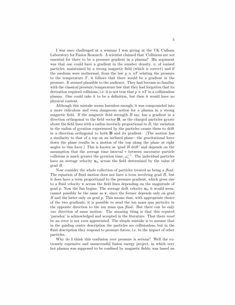
5
I was once challenged at a seminar I was giving at the UK CulhamLaboratory for Fusion Research. A scientist claimed that ‘Collisions are notessential for there to be a pressure gradient in a plasma!’ His argumentwas that one could have a gradient in the number density, n, of ionisedparticles, maintained by a strong magnetic field (which is correct) and ifthe medium were isothermal, from the law p ∝ nT relating the pressureto the temperature T , it follows that there would be a gradient in thepressure. It seemed plausible to the audience. They had become so familiarwith the classical pressure/temperature law that they had forgotten that itsderivation required collisions, i.e. it is not true that p ∝ nT in a collisionlessplasma. One could take it to be a definition, but then it would have nophysical content.
Although this mistake seems harmless enough, it was compounded intoa more ridiculous and even dangerous notion for a plasma in a strongmagnetic field. If the magnetic field strength B say, has a gradient in adirection orthogonal to the field vector B, as the charged particles gyrateabout the field lines with a radius inversely proportional to B, the variationin the radius of gyration experienced by the particles causes them to driftin a direction orthogonal to both B and its gradient. (The motion hasa similarity to that of a top on an inclined plane—the gravitational forcedown the plane results in a motion of the top along the plane at rightangles to this force.) This is known as ‘grad B drift’ and depends on theassumption that the average time interval τ between successive particlecollisions is much greater the gyration time, ω−1
c . The individual particleshave an average velocity uB across the field determined by the value ofgrad B.
Now consider the whole collection of particles treated as being a fluid .The equation of fluid motion does not have a term involving grad B, butit does have a term proportional to the pressure gradient, which gives riseto a fluid velocity v across the field lines depending on the magnitude ofgrad p. Now the fun begins. The average drift velocity uB it would seem,cannot possibly be the same as v, since the former depends only on gradB and the latter only on grad p. This means that, with appropriate choiceof the two gradients, it is possible to send the ion mass qua particles inthe opposite direction to the ion mass qua fluid . But there can be onlyone direction of mass motion. The amazing thing is that this reputed‘paradox’ is acknowledged and accepted in the literature. That there mustbe an error is not even appreciated. The simple mistake is to assume thatin the guiding centre description the particles are collisionless, but in thefluid description they respond to pressure forces, i.e. to the impact of otherparticles.
Why do I think this confusion over pressure is serious? Well the ex-tremely expensive and unsuccessful fusion energy project, in which veryhot plasma was supposed to be confined by magnetic fields, was based on
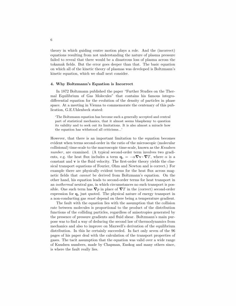
6
theory in which guiding centre motion plays a role. And the (incorrect)equations resulting from not understanding the nature of plasma pressurefailed to reveal that there would be a disastrous loss of plasma across thetokamak fields. But the error goes deeper than that. The basic equationon which all of the kinetic theory of plasmas was developed is Boltzmann’skinetic equation, which we shall next consider.
4. Why Boltzmann’s Equation is Incorrect
In 1872 Boltzmann published the paper “Further Studies on the Ther-mal Equilibrium of Gas Molecules” that contains his famous integro-differential equation for the evolution of the density of particles in phasespace. At a meeting in Vienna to commemorate the centenary of this pub-lication, G.E.Uhlenbeck stated:
‘The Boltzmann equation has become such a generally accepted and centralpart of statistical mechanics, that it almost seems blasphemy to questionits validity and to seek out its limitations. It is also almost a miracle howthe equation has withstood all criticisms...’
However, that there is an important limitation to the equation becomesevident when terms second-order in the ratio of the microscopic (molecularcollisional) time-scale to the macroscopic time-scale, known as the Knudsennumber , are examined. (A typical second-order term involves two gradi-ents, e.g. the heat flux includes a term q2 = −α∇v ·∇T , where α is aconstant and v is the fluid velocity. The first-order theory yields the clas-sical transport equations of Fourier, Ohm and Newton and is correct.) Forexample there are physically evident terms for the heat flux across mag-netic fields that cannot be derived from Boltzmann’s equation. On theother hand, his equation leads to second-order terms for heat transport inan isothermal neutral gas, in which circumstances no such transport is pos-sible. One such term has ∇p in place of ∇T in the (correct) second-orderexpression for q2 just quoted. The physical nature of energy transport ina non-conducting gas must depend on there being a temperature gradient.
The fault with the equation lies with the assumption that the collisionrate between molecules is proportional to the product of the distributionfunctions of the colliding particles, regardless of anisotropies generated bythe presence of pressure gradients and fluid shear. Boltzmann’s main pur-pose was to find a way of deducing the second law of thermodynamics frommechanics and also to improve on Maxwell’s derivation of the equilibriumdistribution. In this he certainly succeeded. In fact only seven of the 96pages of his paper deal with the calculation of the transport properties ofgases. The tacit assumption that the equation was valid over a wide rangeof Knudsen numbers, made by Chapman, Enskog and many others since,is where the fault really lies.
7
In the formulation of the kinetic equation, the distinction between con-vection and diffusion is not correctly drawn. Diffusion is due to molecularagitation superimposed on a reference frame that not only has the speed ofthe fluid element, but which also accelerates and spins with it. This meansthat the pressure gradient must be assumed known from the outset, sincethe fluid element to which the frame is attached, is accelerated by this force.The spurious terms in the heat transport mentioned above, arise becauseof the neglect of these fluid accelerations. For example, scattering is takenwithout comment to be isotropic in a frame that has the velocity of a fluidelement, but not its acceleration. Had the mechanism on which the equa-tion was based, namely the collisional scattering of molecules in and outof a fully convected element of phase-space, been clearly understood andkept in mind, the error would have been soon discovered and the originalBoltzmann’s equation corrected for higher values of the Knudsen number.
Great sums and scientific effort have been invested into finding com-puter solutions of Boltzmann’s equation in the regime of large Knudsennumbers. Such a waste and just because of the apparently unshakeablebelief in equations rather than mechanisms. So far as research in fusion en-ergy is concerned, the cost of the failed tokamak machine world-wide mustexceed ten billion dollars. At least in part this waste can be attributedto the propensity of plasma physicists to adopt a positivistic view of theirscience.
5. Understanding Entropy
My final example of the legacy of positivism comes from that will-o’-the-wisp known as entropy . What is curious about this property of macroscopicsystems is that it is a purely defined quantity, not relating to a physicalproperty until precise details of the state of the system have been specified.And the problem with ‘state’ is that it is observer-dependent , i.e. it dependson what elements the observer wishes to include in his physical model ofthe system under consideration. The greater the detail, the smaller theresulting entropy of the system. In this case the ‘mechanism’ is simply thechosen physical state. Unfortunately the positivist position seems to bethat entropy is a property of systems, independent of the observer—themechanism via state is quite ignored. Examples of this are to be found ina subject optimistically termed ‘rational thermodynamics’, in which tem-perature and entropy are taken to be ‘primitive’ quantities not requiringdefinition.
This ignorance would be harmless enough, except that ‘the’ entropy,or rather its rate of production, σ say, is made the basis for determiningthe form of constitutive relations, namely the laws relating fluxes and thethermodynamic forces driving them. The principle is that these fluxes andforces appear as quadratic products in σ, which it is assumed must always
8
be positive. The second law of thermodynamics is claimed to support thisview. Fourier’s law relating the heat flux q to the temperature gradient∇T , is a simple example. In the absence of other processes, the productionrate is σ = −q ·∇T > 0, which implies that q = −κ∇T , where κ is a pos-itive constant termed the ‘thermal conductivity’. The physical mechanismthat generates these fluxes and that is responsible for σ generally beingpositive is lost in a pseudo-mathematical haze, with the hope no doubtthat the pure mathematical appearance of the formalism will impress thefollowers into believing that the reasoning is unassailable.
Of course this approach leads to gross errors, perhaps the simplest ofwhich is a theorem due to Coleman that asserts the entropy to be inde-pendent of the gradients of temperature and fluid velocity. In a theorycorrect to second-order in the Knudsen number, this is readily shown tobe wrong. Another evident error arises in the theory of heat flux acrossstrong magnetic fields. There is an interesting and very important term q∧
that happens to be orthogonal to both the temperature gradient and themagnetic field. Since q∧ · ∇T = 0, this term does not generate entropy anddoes not appear in the expression for σ. It therefore does not exist for therational thermodynamicist. In fact it is the second-order form of q∧ that isresponsible for the failure of tokamaks to retain their energy for more thana few seconds at best, when minutes would be required for an economicfusion reactor. And the same transport equation plays a dominant role incoronal physics.
The entropy production rate is assumed to be always positive. This ispresented as an axiom, with the second law as justification. Unfortunatelythe second law gives no guarantee that σ is always positive. In a strongmagnetic field it is in fact the case that σ may have either sign. Theargument is as follows. We expand σ as a power series in the Knudsennumber, ε say,
σ ≈ σ1 + σ2,(σi = O(εi)
),
where we have carried the expansion only to the second-order term. Ofthe two terms, only σ1 is dissipative. It is therefore always positive. Thesecond-order term has three gradients and is consequently reversible, i.e.it may have either sign. Moreover it can be much larger than σ1, in whichcase the total σ may be negative. This is not a failure of the second law,which relates only to dissipative terms. The problem is that the rationalthermodynamicist has adopted an axiom, the physical content of which hedoes not understand.
It can be shown that the stability of a continuum flow requires that
σ1 ≥ 0, σ1 + σ2 ≥ 0 ,
the inequalities in which have different roles. The first determines that thethermal conductivity and the fluid viscosity be positive quantities, mak-ing it a thermodynamic constraint; it is universal and independent of the
9
actual flows obtained. The coefficients of the second-order terms, beingdetermined by the same molecular behaviour as the first-order coefficients,are closely related to them, leaving no freedom for further thermodynamicconstraints to be satisfied.
On the other hand the stability constraint ((σ1 + σ2) ≥ 0) can besatisfied only by restricting the class of fluid flows. It sets a limit on thegradients, or equivalently on the Knudsen number making it a macroscopicor fluid constraint. Provided ε is sufficiently small—certainly less thanunity—σ1 will be larger than |σ2| and the constraint will be satisfied. Wemight imagine some initial state, with steep gradients, for which this doesnot hold. The fluid flow may be momentarily unstable, but the resultingfluctuation will quickly restore a new equilibrium state, in which σ2 is eitherpositive, or smaller in magnitude than σ1.
Since the second law of thermodynamics is not normally associated withthe question of the stability or not of the flow field, it is restricted to thethermodynamic constraint, σ1 ≥ 0, while the constraint on (σ1 + σ2) isconcerned solely with the macroscopic stability of the flow field. Certainlywith magnetoplasmas, even with convergent Knudsen number expansions,the O(ε2) terms dominate the classical O(ε) terms by orders of magnitudeand instabilities in which (σ1 +σ2) changes sign periodically do occur. Theadoption of the inequality σ > 0 as an axiom is a serious mistake.
6. Conclusions
I have tried to show that the attitude of scientists to their research—the way they go about it—is greatly influenced by the beliefs they haveadopted, consciously or otherwise, about the nature of the scientific enter-prise. In this way, the philosophy of science does play an important, butindirect role in research, a point of view that would have been quite obviousto most 19th Century scientists. The importance of philosophical concernsin cosmology and quantum physics, in which branches of science there isno shortage of metaphysical invention, is obvious enough, but that thisextends into the classical realms of continuum physics is not sufficientlyappreciated.
University teaching is largely responsible for the inculcation of positivistattitudes in the typical university graduate. Mathematical approaches tophysics and the mathematical sciences are easier to teach and easier tolearn. Mechanisms are not ignored, but they are given less attention, espe-cially where it counts for the average student, namely in the examinationroom. When I was an examiner for Oxford Finals in Mathematics, I al-ways attempted to set some questions essay-type discussions of underlyingphysical principles. But these were seldom answered—they were thoughtto be too difficult and in any case how can one get high marks for a mereessay!
B Henri Coanda’s Propelling Device
82