Embed Size (px)
Citation preview

HISTORIC BALLISTIC FACILITY
AERODYNAMICS RANGE
A NATIONAL HISTORIC MECHANICAL ENGINEERING LANDMARK
THE AMERICAN SOCIETY OF MECHANICAL ENGINEERS
21 OCTOBER 1982
BALLISTIC RESEARCH LABORATORY
ABERDEEN PROVING GROUND, MARYLAND

ABERDEEN PROVING GROUND, MARYLAND
AERODYNAMICS RANGE
NATIONAL HISTORIC MECHANICALENGINEERING LANDMARK*
1 9 4 3This was the world's first large-scale, fully-instrumented
ballistic range producing data on the aerodynamic characteristics ofmissiles in free flight. A host of supersonic aerodynamic designs offour decades have used the information developed here. The facility'sunique technology became the foundation of similar installationsworldwide.
THE AMERICAN SOCIETY OF MECHANICAL ENGINEERS - 1982
SERVICE TO THE NATIONDuring the 1930's, research into advanced ballistic measurement
techniques was begun at Aberdeen Proving Ground. Before the German Armyentered Poland, exceptional data on the flight of projectiles were beingprovided. The crisis of World War II gave incentive to incorporate thispioneering research into the design and construction of the AerodynamicsRange at the U.S. Army Ballistic Research Laboratory. The facility wasunique for its time and established the capability to study, in detail,the aerodynamics of bodies in supersonic free flight. The sequential,high speed photographic instrumentation in the Range has recorded theflight of projectiles, missiles, and aircraft important to the nationaldefense. Personnel, working in this original installation, havecontributed to technical disciplines ranging from photography and highspeed circuit design to the theory of flight. The Range is recognizedas the prototype for similar installations within the United States andabroad.
*The Aerodynamics Range is the 79th Landmark--State, National, and International--tobe designated by the ASME since the program began in 1973. For a complete list andinformation about the ASME History and Heritage Program, please contact the ASMEPublic Information Department, 345 E 47th Street, New York, NY 10017 [212-705-7740].

FIRST MEETING OF THE SCIENTIFIC ADVISORY COMMITTEE, BRL, SEP 1940
generated by the missile passing throughthe coils. The angular motion of theprojectile, which gives a strongindication of flight stability, wasmeasured by firing through an array ofcardboard sheets placed at intervals alongthe trajectory. The dimensions andorientation of the "key hole" that themissile punched in the sheets describedits attitude. These techniques createdproblems since they interfered with theflight of the round and were notsufficiently precise to provide theinformation required by modern theorists.
To improve the quality of ballisticdata, advanced diagnostic techniques wereexamined by R. H. Kent at AberdeenProving Ground. Together with Dr.Alexander C. Charters, Bob Kent developedthe technology which laid the groundworkfor the design of the Aerodynamics Range.Their facility was constructed in time toperform invaluable service during a periodinternational crisis. Fundamentalcontributions were made to the science ofballistics in the areas of dataacquisition and analysis, the theory ofprojectile flight, and the analysis ofsupersonic aerodynamics. Parallel effortsIn the development of tactical andstrategic weapons design data contributedto the security of the free world.
SPARK SHADOWGRAPHY
Accurate observation of fast-movingobjects is essential to progress in manyfields of science and technology. Onemethod to freeze motion is through the useof flash photograghy where a shortduration light source exposes the image on
measurements were not providing useful
In 1742, Benjamin Robins used aballistic pendulum to measure the muzzlevelocity of a projectile fired from acannon. His velocity was much higher thanthose values predicted by existing theory.Basically, the theory assumed the roundwas flying through a vacuum; thereforeonly a modest muzzle velocity was neededto explain the ranges typical of earlyartillery. Robins' experiment presentedthe theorist with a contrary fact and ledto the identification of aerodynamicresistance or drag as a force which had tobe reckoned with. It also confirmed theneed for valid measurements to accompanyanalytic developments.
By the early part of the twentiethcentury, theoretical ballisticians wereagain ahead of their experimentallyinclined brothers. Designers had replacedthe spherical cannon ball with streamlinedshapes typical of modern shell. Whilesuch profiles reduced aerodynamic drag,they also tended to be unstable andrequired spin, obtained from rifled guntubes, to provide gyroscopic stability.If not given sufficient spin, theprojectile would in flight leadingto a drastic increase in drag. Whiletheory could predict performance,
comparisons.
Flight velocities were being measuredby firing a magnetized projectile throughsolenoid coils placed at predeterminedintervals along the trajectory andrecording on a drum chronograph the timeinterval between the electric pulses

TYPICAL SPARK SHADOWGRAPHS
SPIN-STABILIZED PROJECTILE MISSILE
film. One of the shortest duration lightsources available is the spark discharge.The first spark photograph was made in1851, when an unblurred picture of anewspaper clipping attached to a revolvingdrum was obtained by use of a spark from aLeyden cell. While significant advanceshad been made since the first experiment,there remained much to be done before thetechnique could be used to photograph thefree flight of projectiles.
There were three basic requirementsfor a ballistic spark photography range:a light source one-millionth of a secondin duration and of sufficient intensity toexpose a photographic plate; interferencefree synchronization of the light sourcetriggering with the passage of theprojectile; and arranging an array ofphotographic stations along the trajectoryin sufficient density to provide usefuldata.
By 1940, typical exposure times wereone-ten thousandth of a second;unfortunately, this led to a photograph ofa caliber 0.50 bullet appearing as a4-inch blur. Dr. A. C. Charters of BRLtogether with Dr. Lewi Tonks of GeneralElectric Company, Schenectady, developed ahigh speed spark gap with durations ofone-microsecond. This permitted theacquisition of high quality photographs ofprojectiles in flight. To solve thetriggering problem, the design team tookadvantage of a phenomenon first observedin research by the Italian Army, namely,the build-up of an electrostatic charge ona projectile in flight. Since a movingcharge produces a magnetic field, Charters
and Tonks realized that this field couldbe detected and used to provide anon-intrusive trigger source tosynchronize the photographic systems.
Once the instrumentation was proven,the Aerodynamics Range was initiallyconfigured with fifty, orthogonal sparkshadowgraph stations positioned along its300-foot length. Timing data on sparkfiring was recorded on a drum chronographand, subsequently, on electronic counters.Accurate interpretation of the massiveamounts of data produced by the Rangerequired a considerable amount ofanalytical work. From the set of onehundred photographs, the spatial locationand orientation of the projectile had tobe computed. To insure accuracy in thesecalculations, the Range had to beprecisely surveyed. The analysis andsurvey systems were developed in parallelwith the physical plant by BRLmathematicians and scientists.
When put into use in 1943, the BRLAerodynamics Range made possible, for thefirst time, the recording of accuratehistories not only of projectile motion,but also of the detailed, transient flowstructure about the round. Although thesize of the Range limited its use tomissiles of 4Omm and less in diameter,there were no limitations placed on theimagination of the operational staff or onthe configurations which required testing.By developing pioneering launchtechniques, they were able to contributeto studies of projectile, missile, andaircraft aerodynamics in all flightregimes from subsonic through hypersonicvelocities.
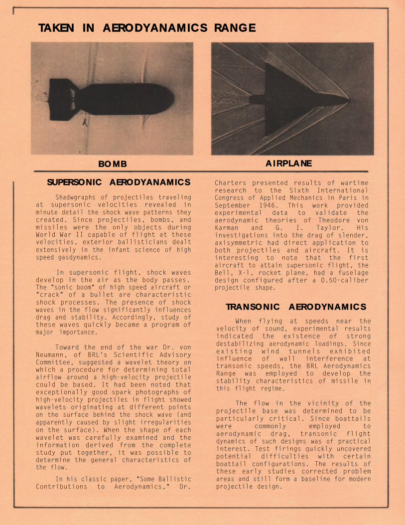
BOMB
SUPERSONIC AERODYANAMICS
Shadwgraphs of projectiles travelingat supersonic velocities revealed inminute detail the shock wave patterns theycreated. Since projectiles, bombs, andmissiles were the only objects duringWorld War II capable of flight at thesevelocities, exterior ballisticians dealtextensively in the infant science of highspeed gasdynamics.
In supersonic flight, shock wavesdevelop in the air as the body passes.The "sonic boom" of high speed aircraft or"crack" of a bullet are characteristicshock processes. The presence of shockwaves in the flow significantly influencesdrag and stability. Accordingly, study ofthese waves quickly became a program ofmajor importance.
Toward the end of the war Dr. vonNeumann, of BRL's Scientific AdvisoryCommittee, suggested a wavelet theory onwhich a procedure for determining totalairflow around a high-velocity projectilecould be based. It had been noted thatexceptionally good spark photographs ofhigh-velocity projectiles in flight showedwavelets originating at different pointson the surface behind the shock wave (andapparently caused by slight irregularitieson the surface). When the shape of eachwavelet was carefully examined and theinformation derived from the completestudy put together, it was possible todetermine the general characteristics ofthe flow.
In his classic paper, "Some BallisticContributions to Aerodynamics," Dr.
Charters presented results of wartimeresearch to the Sixth InternationalCongress of Applied Mechanics in Paris inSeptember 1946. This work providedexperimental data to validate theaerodynamic theories of Theodore vonKarman and G. I. Taylor. Hisinvestigations into the drag of slender,axisymmetric had direct application toboth projectiles and aircraft. It isinteresting to note that the firstaircraft to attain supersonic flight, theBell, X-l, rocket plane, had a fuselagedesign configured after a 0.50-caliberprojectile shape.
TRANSONIC AERODYNAMICS
When flying at speeds near thevelocity of sound, experimental resultsindicated the existence of strongdestabilizing aerodynamic loadings. Sinceexisting wind tunnels exhibitedinfluence of wall interference attransonic speeds, the BRL AerodynamicsRange was employed to develop thestability characteristics of missile inthis flight regime.
The flow in the vicinity of theprojectile base was determined to beparticularly critical. Since boattailswere commonly employed toaerodynamic drag, transonic flightdynamics of such designs was of practicalinterest. Test firings quickly uncoveredpotential difficulties with certainboattail configurations. The results ofthese early studies corrected problemareas and still form a baseline for modernprojectile design.
TAKEN IN AERODYANAMICS RANGE
AIRPLANE

Another flight vehicle with transonicproblems were bombs dropped from highaltitude. As they accelerated, the bombspassed through transonic velocities whereflight instabilities could developinfluencing accuracy and proper fuzefunctioning. Many bomb models were firedin the Aerodynamics Range to correct oruncover potential difficulties. Among themore important were the early atomic bombshapes.
SERVICE SUPPORT
To give maximum assistance to weaponsand ammunition designers the exteriorballisticians at BRL devoted aconsiderable part of their time to servicework. Models of new designs of shell,rockets, guided missiles, and bombs weretested in the free flight range to providedata needed by designers. In addition, alarge amount of troubleshooting was doneto determine, for example, what caused anew shell to be unstable in flight or anew rocket to be inaccurate.
The munition developments of WorldWar II were considerable. Thefin-stabilized, kinetic energy projectilewas introduced by Germany late in the war.These projectiles were found to beinaccurate if they possessed aerodynamicor inertial asymmetries. Tests at BRLdemonstrated that the effect of theseasymmetries could be reduced, with anassociated accuracy improvement, if aninitial spin or roll was imparted to theround. However, it was also discoveredthat the permissible spin rate haddefinite limits. If it was too fast, aside force developed leading toinstability. If it was too slow,resonance between roll and yawing motioncould result leading to "catastrophic"growth in the yaw angle. These conceptsform a basis of design for all modernfin-stabilized rounds.
A fundamental contribution to thedesign of high explosive, shaped chargeprojectiles was made almost accidentally.During experiments to measure the drag onsharp- and blunt-nosed projectiles, it wasfound that the addition of a spike,protruding from the nose of a bluntprojectile reduced the drag to a valuenear that of the streamlined designwithout the associated loss of stability.
These results formed the basis for thedesign of the fin- stabilized, spike-nosedprojectiles currently used with shapedcharge warheads.
When high speed aircraft wereintroduced during and following the war,they imposed conditions of fire sodifferent that completely new techniquesfor predicting flight characteristics ofprojectiles fired from aircraft guns hadto be developed. In this case, the speedof the aircraft was a major factoraffecting both the velocity and the yaw ofprojectiles. Heretofore, when the effectsof aircraft speed were much lesspronounced, the ballistics of suchprojectiles could be determinedexperimentally by ground firings. Withmodern aircraft, this data did nottransfer to flight tests. Subsequently,Aerodynamics Range tests to measure thedynamic stability characteristics ofrounds fired under the realisticconditions readily demonstrated that firecontrol solutions were incorrect. Basedon validated aerodynamics, new solutionswere computed which permitted accuratefire.
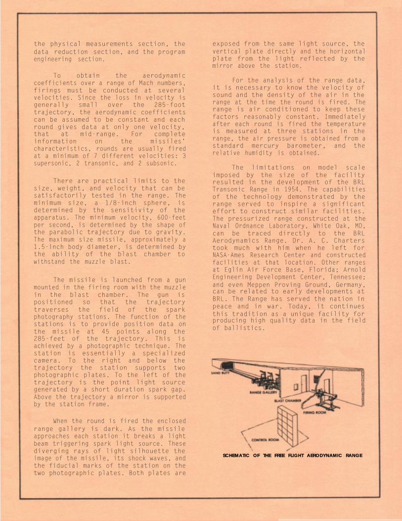
The range area consists of the firingroom containing the launcher, the blastchamber isolating the instrument area fromthe muzzle blast, the range gallerycontaining the apparatus for recording theflight of the missile, and the controlroom from which operations and datarecording are conducted. Additionalfacilities and activities necessary toobtain ballistic data are the model shops,
The Aerodynamics Range is an enclosedfacility instrumented to launch a missilein free flight and record its motion over285-feet of the trajectory. The techniquefor obtaining the aerodynamic coefficientsdemands unusual accuracy in themeasurement of time, distance, and angle.The required accuracy in distance andangle was developed using sparkphotography. This recording proceduregives distance accuracy to O.OO1-foot andangular accuracy to 2-minutes of arc. Theroll angle can be determined to anaccuracy of less than 1-degree. Timeinterval measurements are obtained to anaccuracy of O-1-microsecond.
MECHANICAL SPECIFICATIONS
the physical measurements section, thedata reduction section, and the programengineering section.
To obtain the aerodynamiccoefficients over a range of Mach numbers,firings must be conducted at severalvelocities. Since the loss in velocity isgenerally small over the 285-foottrajectory, the aerodynamic coefficientscan be assumed to be constant and eachround gives data at only one velocity,that at mid-range. For completeinformation on the missiles'characteristics, rounds are usually firedat a minimum of 7 different velocities: 3supersonic, 2 transonic, and 2 subsonic.
There are practical limits to thesize, weight, and velocity that can besatisfactorily tested in the range. Theminimum size, a 1/8-inch sphere, isdetermined by the sensitivity of theapparatus. The minimum velocity, 600-feetper second, is determined by the shape ofthe parabolic trajectory due to gravity.The maximum size missile, approximately a1.5-inch body diameter, is determined bythe ability of the blast chamber towithstand the muzzle blast.
The missile is launched from a gunmounted in the firing room with the muzzlein the blast chamber. The gun ispositioned so that the trajectorytraverses the field of the sparkphotography stations. The function of thestations is to provide position data onthe missile at 45 points along the285-feet of the trajectory. This isachieved by a photographic technique. Thestation is essentially a specializedcamera. To the right and below thetrajectory the station supports twophotographic plates. To the left of thetrajectory is the point light sourcegenerated by a short duration spark gap.Above the trajectory a mirror is supportedby the station frame.
When the round is fired the enclosedrange gallery is dark. As the missileapproaches each station it breaks a lightbeam triggering spark light source. Thesediverging rays of light silhouette theimage of the missile, its shock waves, andthe fiducial marks of the station on thetwo photographic plates. Both plates are
exposed from the same light source, thevertical plate directly and the horizontalplate from the light reflected by themirror above the station.
For the analysis of the range data,it is necessary to know the velocity ofsound and the density of the air in therange at the time the round is fired. Therange is air conditioned to keep thesefactors reasonably constant. Immediatelyafter each round is fired the temperatureis measured at three stations in therange, the air pressure is obtained from astandard mercury barometer, and therelative humidity is obtained.
The limitations on model scaleimposed by the size of the facilityresulted in the development of the BRLTransonic Range in 1954. The capabilitiesof the technology demonstrated by therange served to inspire a significanteffort to construct similar facilities.The pressurized range constructed at theNaval Ordnance Laboratory, White Oak, MD,can be traced directly to the BRLAerodynamics Range. Dr. A. C. Charterstook much with him when he left forNASA-Ames Research Center and constructedfacilities at that location. Other rangesat Eglin Air Force Base, Florida; ArnoldEngineering Development Center, Tennessee;and even Meppen Proving Ground, Germany,can be related to early developments atBRL. The Range has served the nation inpeace and in war. Today, it continuesthis tradition as a unique facility forproducing high quality data in the fieldof ballistics.
SCHEMATIC OF THE FREE FLIGHT AERODYNAMIC RANGE

ACKNOWLEDGEMENTS
The Baltimore Section of the American Society of Mechanical Engineers gratefullyacknowledges the efforts of all who cooperated in the dedication of the AerodynamicsRange as a National Historic Mechanical Engineering Landmark. Particular thanks aredue to the staff at the Ballistic Research Laboratory who participated in theproduction of the commemerative brochure and the arrangements for the dedicationceremony.
The American Society of Mechanical Engineers
Dr. Serge Gratch, PresidentGeorge Kotnick, GovernorPaul Allmendinger, Deputy Executive DirectorWilliam H. Coleman, Vice President, Region IIIJohn L. Bloomquist, History and Heritage, Region III
The Baltimore Section
Thomas S. Larson, ChairmanF. James Schroeder, Vice ChairmanE. Frank Bender, SecretaryL. J. Steinitz, TreasurerErnest M. Stolberg, History and Heritage
The ASME National History and Heritage Committee
Dr. R. Carson Dalzell, SecretaryProf. R. S. HartenbergDr. J. Paul HartmanProf. Edwin T. Layton, Jr.Prof. Merritt Roe SmithRobert M. Vogel, Ex-officio, Smithsonian Institution
The Ballistic Research Laboratory
Dr. Robert J. Eichelberger, DirectorCOL R. N. Mathis, Commander/Deputy DirectorDr. Charles H. Murphy, Chief, Launch and Flight DivisionMr. L. C. MacAllister, Chief, Free Flight Aerodynamics BranchDr. Edward M. Schmidt, Chief, Fluid Physics Branch - Author, Commemerative Brochure
H080