Embed Size (px)
Citation preview
CompEdu HPT / S5: Aeroelasticity / B1: Introduction / C1: Basic Introduction to Aeroelasticity T. H. Fransson
1
AEROELASTICITY IN AXIAL-FLOWTURBOMACHINES
Torsten H. Fransson
Book 1:INTRODUCTION
Chapter 1:
Basic Introduction to Aeroelasticity
SUMMARY
This introductory section gives an overview, from an historical perspective, of varioustypes of aeroelastic problems that have appeared in a few engineering fields. Itdescribes some failures that have appeared and what the research has indicated aspossible causes. The basic definitions of static and dynamic aeroelasticity areintroduced. Some references to basic text books on the subject of aeroelasticity aregiven.
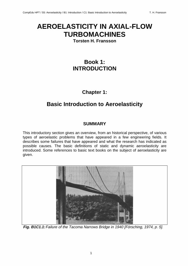
Fig. B1C1.1:Failure of the Tacoma Narrows Bridge in 1940 [Försching, 1974, p. 5].
CompEdu HPT / S5: Aeroelasticity / B1: Introduction / C1: Basic Introduction to Aeroelasticity T. H. Fransson
2
THE PROBLEM AND THE HISTORY
Vibration-related failures of structures are of a large importance in many aspects ofmechanical engineering. Problems may appear as a sudden destruction or can berelated to longer-term fatigue of the structure, and they may be related to an eventualflow of fluid around the structure (called for example "flow induced vibrations", "flow-structure interaction" or "fluid-elasticity") or be purely structural. It is widelyrecognized that flow induced vibrations are of major concern in the design of modernengineering structures, as the continuous interaction between a vibrating structureand the changing flow characteristics can cause high stresses leading to short-termfatigue failure. A non-optimal development of a structure can, especially inaeronautics, where development costs are extremely high, have a significantinfluence on the viability of the final product.
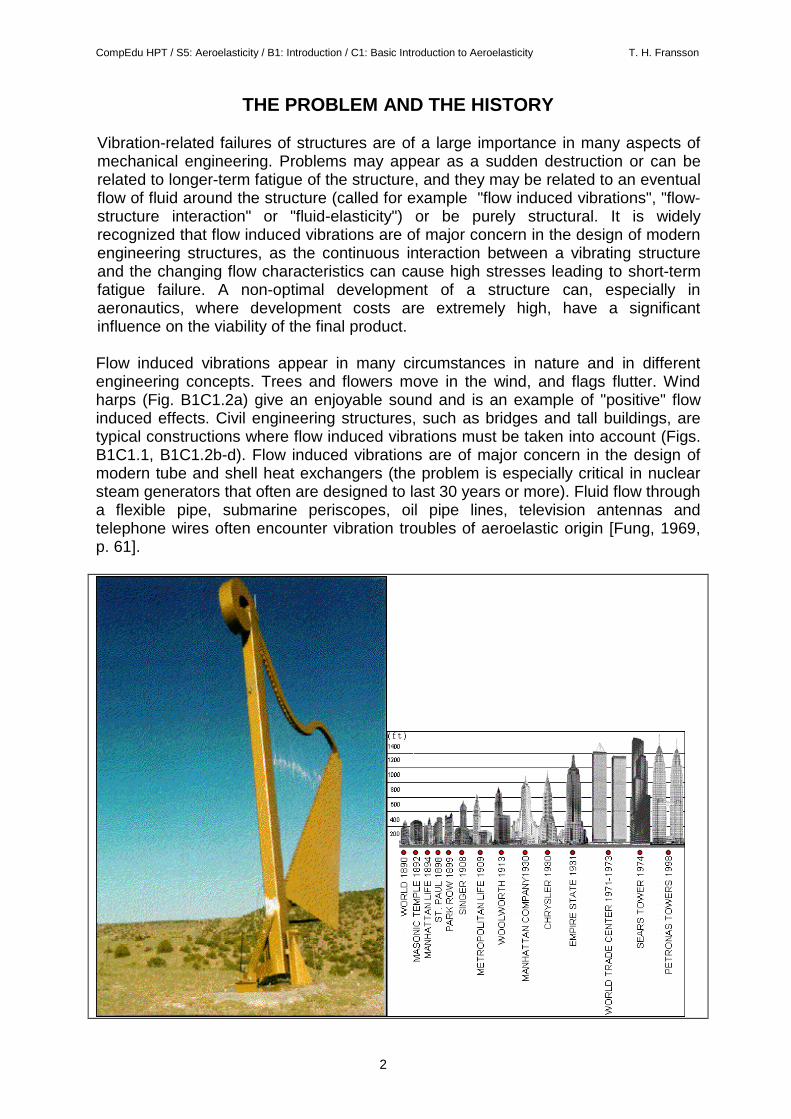
Flow induced vibrations appear in many circumstances in nature and in differentengineering concepts. Trees and flowers move in the wind, and flags flutter. Windharps (Fig. B1C1.2a) give an enjoyable sound and is an example of "positive" flowinduced effects. Civil engineering structures, such as bridges and tall buildings, aretypical constructions where flow induced vibrations must be taken into account (Figs.B1C1.1, B1C1.2b-d). Flow induced vibrations are of major concern in the design ofmodern tube and shell heat exchangers (the problem is especially critical in nuclearsteam generators that often are designed to last 30 years or more). Fluid flow througha flexible pipe, submarine periscopes, oil pipe lines, television antennas andtelephone wires often encounter vibration troubles of aeroelastic origin [Fung, 1969,p. 61].
CompEdu HPT / S5: Aeroelasticity / B1: Introduction / C1: Basic Introduction to Aeroelasticity T. H. Fransson
3
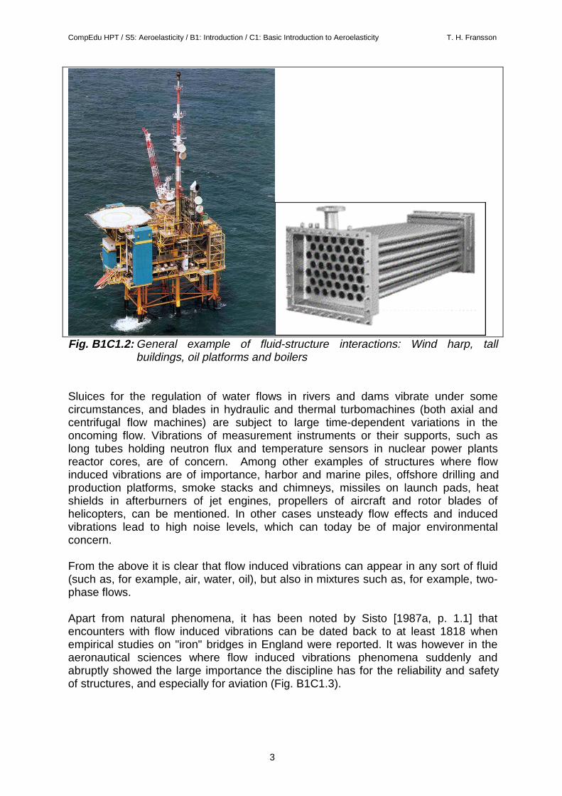
Fig. B1C1.2: General example of fluid-structure interactions: Wind harp, tallbuildings, oil platforms and boilers
Sluices for the regulation of water flows in rivers and dams vibrate under somecircumstances, and blades in hydraulic and thermal turbomachines (both axial andcentrifugal flow machines) are subject to large time-dependent variations in theoncoming flow. Vibrations of measurement instruments or their supports, such aslong tubes holding neutron flux and temperature sensors in nuclear power plantsreactor cores, are of concern. Among other examples of structures where flowinduced vibrations are of importance, harbor and marine piles, offshore drilling andproduction platforms, smoke stacks and chimneys, missiles on launch pads, heatshields in afterburners of jet engines, propellers of aircraft and rotor blades ofhelicopters, can be mentioned. In other cases unsteady flow effects and inducedvibrations lead to high noise levels, which can today be of major environmentalconcern.
From the above it is clear that flow induced vibrations can appear in any sort of fluid(such as, for example, air, water, oil), but also in mixtures such as, for example, two-phase flows.
Apart from natural phenomena, it has been noted by Sisto [1987a, p. 1.1] thatencounters with flow induced vibrations can be dated back to at least 1818 whenempirical studies on "iron" bridges in England were reported. It was however in theaeronautical sciences where flow induced vibrations phenomena suddenly andabruptly showed the large importance the discipline has for the reliability and safetyof structures, and especially for aviation (Fig. B1C1.3).
CompEdu HPT / S5: Aeroelasticity / B1: Introduction / C1: Basic Introduction to Aeroelasticity T. H. Fransson
4
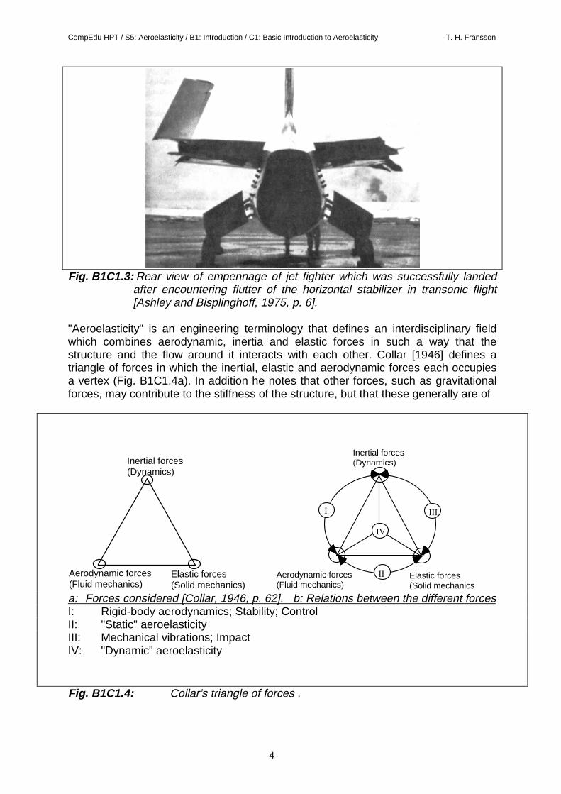
Fig. B1C1.3: Rear view of empennage of jet fighter which was successfully landedafter encountering flutter of the horizontal stabilizer in transonic flight[Ashley and Bisplinghoff, 1975, p. 6].
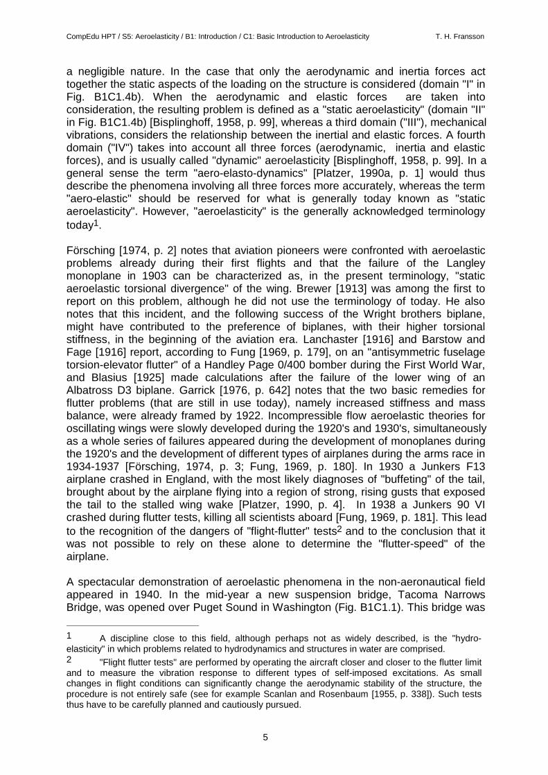
"Aeroelasticity" is an engineering terminology that defines an interdisciplinary fieldwhich combines aerodynamic, inertia and elastic forces in such a way that thestructure and the flow around it interacts with each other. Collar [1946] defines atriangle of forces in which the inertial, elastic and aerodynamic forces each occupiesa vertex (Fig. B1C1.4a). In addition he notes that other forces, such as gravitationalforces, may contribute to the stiffness of the structure, but that these generally are of
Aerodynamic forces (Fluid mechanics)
Elastic forces (Solid mechanics)
Inertial forces (Dynamics)
Aerodynamic forces (Fluid mechanics)
Elastic forces (Solid mechanics
Inertial forces (Dynamics)
I
II
III
IV
a: Forces considered [Collar, 1946, p. 62]. b: Relations between the different forcesI: Rigid-body aerodynamics; Stability; ControlII: "Static" aeroelasticityIII: Mechanical vibrations; ImpactIV: "Dynamic" aeroelasticity
Fig. B1C1.4: Collar’s triangle of forces .
CompEdu HPT / S5: Aeroelasticity / B1: Introduction / C1: Basic Introduction to Aeroelasticity T. H. Fransson
5
a negligible nature. In the case that only the aerodynamic and inertia forces acttogether the static aspects of the loading on the structure is considered (domain "I" inFig. B1C1.4b). When the aerodynamic and elastic forces are taken intoconsideration, the resulting problem is defined as a "static aeroelasticity" (domain "II"in Fig. B1C1.4b) [Bisplinghoff, 1958, p. 99], whereas a third domain ("III"), mechanicalvibrations, considers the relationship between the inertial and elastic forces. A fourthdomain ("IV") takes into account all three forces (aerodynamic, inertia and elasticforces), and is usually called "dynamic" aeroelasticity [Bisplinghoff, 1958, p. 99]. In ageneral sense the term "aero-elasto-dynamics" [Platzer, 1990a, p. 1] would thusdescribe the phenomena involving all three forces more accurately, whereas the term"aero-elastic" should be reserved for what is generally today known as "staticaeroelasticity". However, "aeroelasticity" is the generally acknowledged terminologytoday1.
Försching [1974, p. 2] notes that aviation pioneers were confronted with aeroelasticproblems already during their first flights and that the failure of the Langleymonoplane in 1903 can be characterized as, in the present terminology, "staticaeroelastic torsional divergence" of the wing. Brewer [1913] was among the first toreport on this problem, although he did not use the terminology of today. He alsonotes that this incident, and the following success of the Wright brothers biplane,might have contributed to the preference of biplanes, with their higher torsionalstiffness, in the beginning of the aviation era. Lanchaster [1916] and Barstow andFage [1916] report, according to Fung [1969, p. 179], on an "antisymmetric fuselagetorsion-elevator flutter" of a Handley Page 0/400 bomber during the First World War,and Blasius [1925] made calculations after the failure of the lower wing of anAlbatross D3 biplane. Garrick [1976, p. 642] notes that the two basic remedies forflutter problems (that are still in use today), namely increased stiffness and massbalance, were already framed by 1922. Incompressible flow aeroelastic theories foroscillating wings were slowly developed during the 1920's and 1930's, simultaneouslyas a whole series of failures appeared during the development of monoplanes duringthe 1920's and the development of different types of airplanes during the arms race in1934-1937 [Försching, 1974, p. 3; Fung, 1969, p. 180]. In 1930 a Junkers F13airplane crashed in England, with the most likely diagnoses of "buffeting" of the tail,brought about by the airplane flying into a region of strong, rising gusts that exposedthe tail to the stalled wing wake [Platzer, 1990, p. 4]. In 1938 a Junkers 90 VIcrashed during flutter tests, killing all scientists aboard [Fung, 1969, p. 181]. This leadto the recognition of the dangers of "flight-flutter" tests2 and to the conclusion that itwas not possible to rely on these alone to determine the "flutter-speed" of theairplane.
A spectacular demonstration of aeroelastic phenomena in the non-aeronautical fieldappeared in 1940. In the mid-year a new suspension bridge, Tacoma NarrowsBridge, was opened over Puget Sound in Washington (Fig. B1C1.1). This bridge was
1 A discipline close to this field, although perhaps not as widely described, is the "hydro-elasticity" in which problems related to hydrodynamics and structures in water are comprised.2 "Flight flutter tests" are performed by operating the aircraft closer and closer to the flutter limitand to measure the vibration response to different types of self-imposed excitations. As smallchanges in flight conditions can significantly change the aerodynamic stability of the structure, theprocedure is not entirely safe (see for example Scanlan and Rosenbaum [1955, p. 338]). Such teststhus have to be carefully planned and cautiously pursued.
CompEdu HPT / S5: Aeroelasticity / B1: Introduction / C1: Basic Introduction to Aeroelasticity T. H. Fransson
6
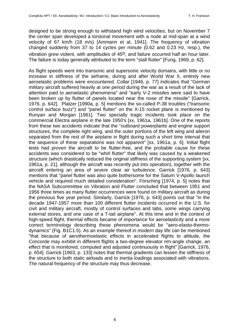
designed to be strong enough to withstand high wind velocities, but on November 7the center span developed a torsional movement with a node at mid-span at a windvelocity of 67 km/h (18 m/s) [Ammann et al, 1941]. The frequency of vibrationchanged suddenly from 37 to 14 cycles per minute (0.62 and 0.23 Hz, resp.), thevibration grew violent, with amplitudes of 45o, and failure occurred half an hour later.The failure is today generally attributed to the term "stall flutter" [Fung, 1969, p. 62].
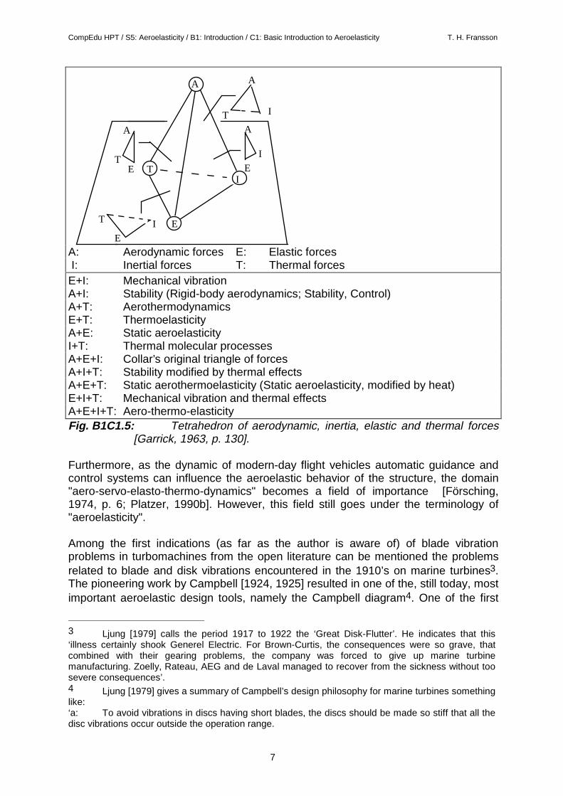
As flight speeds went into transonic and supersonic velocity domains, with little or noincrease in stiffness of the airframe, during and after World War II, entirely newaeroelastic problems were encountered. Collar [1946, p. 77] indicates that "Germanmilitary aircraft suffered heavily at one period during the war as a result of the lack ofattention paid to aeroelastic phenomena" and "early V-2 missiles were said to havebeen broken up by flutter of panels located near the nose of the missile" [Garrick,1976, p. 642]. Platzer [1990a, p. 5] mentions the so-called P-38 troubles ("transoniccontrol surface buzz") and "panel flutter" on the X-15 rocket plane is mentioned byRunyan and Morgan [1961]. Two specially tragic incidents took place on thecommercial Electra airplane in the late 1950’s [xx, 1961a, 1961b]. One of the reportsfrom these two accidents indicate that the "outboard powerplants and engine supportstructures, the complete right wing, and the outer portions of the left wing and aileronseparated from the rest of the airplane in flight during such a short time interval thatthe sequence of these separations was not apparent" [xx, 1961a, p. 6]. Initial flighttests had proven the aircraft to be flutter-free, and the probable cause for theseaccidents was considered to be "whirl flutter" that likely was caused by a weakenedstructure (which drastically reduced the original stiffness of the supporting system [xx,1961a, p. 21], although the aircraft was recently put into operation), together with theaircraft entering an area of severe clear air turbulence. Garrick [1976, p. 643]mentions that "panel flutter was also quite bothersome for the Saturn V-Apollo launchvehicle and required much detailed consideration". Försching [1974, p. 5] notes thatthe NASA Subcommittee on Vibration and Flutter concluded that between 1951 and1956 three times as many flutter occurrences were found on military aircraft as duringthe previous five year period. Similarly, Garrick [1976, p. 643] points out that "in thedecade 1947-1957 more than 100 different flutter incidents occurred in the U.S. forcivil and military aircraft, mostly of control surfaces and tabs, some wings carryingexternal stores, and one case of a T-tail airplane". At this time and in the context ofhigh-speed flight, thermal effects became of importance for aeroelasticity and a morecorrect terminology describing these phenomena would be "aero-elasto-thermo-dynamics" (Fig. B1C1.5). As an example thereof in modern day life can be mentioned"that because of aerothermoelastic effects in accelerated flights to altitude, theConcorde may exhibit in different flights a two-degree elevator rim-angle change, aneffect that is monitored, computed and adjusted continuously in flight" [Garrick, 1976,p. 654]. Garrick [1963, p. 133] notes that thermal gradients can lessen the stiffness ofthe structure to both static airloads and to inertia loadings associated with vibrations.The natural frequency of the structure may thus decrease.
CompEdu HPT / S5: Aeroelasticity / B1: Introduction / C1: Basic Introduction to Aeroelasticity T. H. Fransson
7
E E
T
A
I
T
E
I
A
T E
A
I
E
A
T I
A: Aerodynamic forces E: Elastic forces I: Inertial forces T: Thermal forcesE+I: Mechanical vibrationA+I: Stability (Rigid-body aerodynamics; Stability, Control)A+T: AerothermodynamicsE+T: ThermoelasticityA+E: Static aeroelasticityI+T: Thermal molecular processesA+E+I: Collar’s original triangle of forcesA+I+T: Stability modified by thermal effectsA+E+T: Static aerothermoelasticity (Static aeroelasticity, modified by heat)E+I+T: Mechanical vibration and thermal effectsA+E+I+T: Aero-thermo-elasticityFig. B1C1.5: Tetrahedron of aerodynamic, inertia, elastic and thermal forces
[Garrick, 1963, p. 130].
Furthermore, as the dynamic of modern-day flight vehicles automatic guidance andcontrol systems can influence the aeroelastic behavior of the structure, the domain"aero-servo-elasto-thermo-dynamics" becomes a field of importance [Försching,1974, p. 6; Platzer, 1990b]. However, this field still goes under the terminology of"aeroelasticity".
Among the first indications (as far as the author is aware of) of blade vibrationproblems in turbomachines from the open literature can be mentioned the problemsrelated to blade and disk vibrations encountered in the 1910’s on marine turbines3.The pioneering work by Campbell [1924, 1925] resulted in one of the, still today, mostimportant aeroelastic design tools, namely the Campbell diagram4. One of the first
3 Ljung [1979] calls the period 1917 to 1922 the ‘Great Disk-Flutter’. He indicates that this‘illness certainly shook Generel Electric. For Brown-Curtis, the consequences were so grave, thatcombined with their gearing problems, the company was forced to give up marine turbinemanufacturing. Zoelly, Rateau, AEG and de Laval managed to recover from the sickness without toosevere consequences’.4 Ljung [1979] gives a summary of Campbell’s design philosophy for marine turbines somethinglike:‘a: To avoid vibrations in discs having short blades, the discs should be made so stiff that all thedisc vibrations occur outside the operation range.

CompEdu HPT / S5: Aeroelasticity / B1: Introduction / C1: Basic Introduction to Aeroelasticity T. H. Fransson
8
early overview-discussion about turbine troubles and their causes was given byMellanby and Kerr [1923]. They discussed vibration problems due to distortion effectsand blade passing to a great length (as well as lacing wires on end blades of largereaction turbines), but (obviously) no mention of self-excited aeroelastic effects wereat that time given. The importance of the position of the lacing wires was already thendiscussed [for ex. on p. 36].
Towards the mid- and end 1940’s the first indications (as far as the author is awareof) about the possibility of ‘self-excited’ (or ‘flutter’) problems on blades in axial-flowturbomachines appeared in the open technical literature [Shannon, 1945; Owens andTrumpler, 1949; Bellenot and d'Epinay, 1950; Lilley, 1952; Sisto, 1953; Söhngen andQuick, 19xx; Wang et al, 1956; Lane, 1956]. These reports show that blade failures inthese early days often were due to one degree-of-freedom bending rather thantorsional vibrations [Schnittger, 1958, p. 152] (not a flutter coalescence mode as onan airfoil), and efforts to solve the problems were concentrated on close-to-stalloperating conditions. The most general remedy at the time was to stiffen the bladessufficiently to build in enough mechanical (or aerodynamic) damping or to use tipshrouding [Schnittger, 1958, p. 154] or lacing wires [Bellenot and d'Epinay, 1950, p.369]5. Armstrong and Stevenson [1960] gave an empirical rule stating that thereduced frequency of the blade (k=2πfc/U1) should not be less than 0.33 for thebending frequency and 1.6 for the torsion frequency in order to avoid blade stallflutter, and they point out that in the early days of compressor aeroelasticity the flutterappeared exclusively in the fundamental bending or torsion modes. Such empiricalfactors are today still used for a "safe" design of a turbomachine blade. As anexample can be mentioned a recent report by O'Neill [1989, p. 5] who reports crackson the third row of turbine blades, that were thought to come from flutter, on a42.5MW gas turbine. The experience from this machine indicated that a reducedfrequency (based on outlet flow velocity for the turbine) of k>0.328 defined a safelimit, in considerable agreement with the empirical criteria established by Armstrongand Stevenson 30 years earlier.
As the turbomachine environment is very complex (much more so than the externalflow in aeronautical applications) it is today impossible to define which problems inthose early days appeared because of interaction between neighboring blade rows(forced response problems) and which should be attributed to self-excited vibrations(flutter). Although these two problems are today distinguished as different disciplinesit is still now not always easy to separate them from each other and to define theexact reason for why a blade failure occurs (as the analysis has to be done after thefailure has occurred and as, obviously, large efforts are made not to repeat theexperience). Whitehead [1980, p. 6.3] points out that "many cases of blade failure b: For discs having long blades, where the combined blade and disc vibrations cannot beavoided within the operating range, the blades and discs should be made so stiff that resonance canfirst occur at frequencies higher than the natural frequency for four nodal diameters. This generallygives adequate securityc: To avoid tangential blade vibrations, none of the natural frequencies of the blades can beallowed to coincide with steam impulses from the guide vanes within the operation range.Downstream from each guide vane a turbulent path occurs, and the excitation frequency of thesedisturbances is therefore the number of guide vanes multiplied by the rotating speed. The naturalfrequency of the blade must lie at an adequate distance from this impulse frequency.’5 Fan-stages in modern jet-engines encounters rather coupled bending/torsion flutter, largelybecause of the use of part-span shrouds [Carta and Platzer, 1987, Vol. 2, p. 18.6]
CompEdu HPT / S5: Aeroelasticity / B1: Introduction / C1: Basic Introduction to Aeroelasticity T. H. Fransson
9
which have been put down as forced vibration have in fact been due to a nearapproach to a flutter situation, in which the aerodynamic damping of the vibration hasbecome very small".
Although enormous progresses have been made in the field of aeroelasticity in axial-flow turbomachines during the last four decennia, it is likely that aeroelastic problemswill remain of importance for years to come, both in aeroengines and industrialturbomachines (as well as in many other fields, for example in aeronautical and civilengineering), as modern turbomachines are pushed towards higher fuel efficiencyand higher performances, with increasing temperatures and velocities of the flow,higher aerodynamic efficiencies and lighter materials of the structures. Theseadvances in technology forces the designer to predict vibration-free (flutter and forcedresponse, as well as any other vibration problem) operating ranges for conditionsbeyond regions of available empirical data. Forced response problems may appear inany part of the multistage machine, whereas most flutter problems that appear inaxial-flow turbomachines are related to the blades with the lowest eigen-frequencies.High aspect ratio fan blades, steam and gas turbine blades, accompanied withtransonic flow conditions, are most susceptible to come into flutter. Althoughproblems appear regularly, it is seldom that major discussions appear in the openliterature. Aeroelastic problems that lead to failures are today mostly (and rightly)regarded as negative publicity and are not widely advertised, especially in domainswhere the competition between different companies is fierce, such asturbomachinery. Most analysis, descriptions and expertise of aeroelastic problems inturbomachines thus stay within the companies, or are sometimes mentioned just in ashort sentence of a commercial publication. Every now and then a technical articletreats a specific problem, but most scientific information has to be taken from briefnotes in "User’s" magazines (such as "Aviation Week", "Electricity International" or"International Power Generation", to mention a few), from articles treating cascadeflow, and from specialized technical conferences. A few examples of turbomachineblade failures under true operating conditions, mentioned in the open literature duringthe three last decennia are given below:• Cavaillé stated in 1972 [p. 2] that aeroelastic phenomena are "quite important
for low-pressure steam turbine blades when they are 1 m high and simplycantilevered".
• Sears et al [1976, p. 316]: "Steam people will agree that their last stages arefluttering, whether it is stall flutter or negative incidence flutter is not entirelyclear, but they are probably getting both types at different times"
• A short note in Electricity International [1989, p. 10] indicates that a 160MWgas turbine in the Netherlands was taken out of service in 1988 because ofshaft vibrations. The increased shaft vibration was found to appear because ofa breakage of a blade of the fifth (last) row of stationary blades of the gasturbine, as these were overstressed by vibrations occurring during transientson startup and shutdown.
• Pigott and Abel [1974, p. 206] reports that a third mode oscillation could beself-excited for long low pressure steam turbine blades (laced together ingroups of four) at low flow rates, provided the back pressure was sufficientlyhigh. Silvestri [1981, p. 67] states that “instances of blade flutter and resultingblade failure occurred on some units operating at low exhaust volumetric flowsin the early 1970's".
CompEdu HPT / S5: Aeroelasticity / B1: Introduction / C1: Basic Introduction to Aeroelasticity T. H. Fransson
10
• Extended flutter studies have been performed on the F100 engine developedfor the F-15 fighter aircraft [Jeffers and Meece, 1975; Nieberding and Pollack,1977; Chi, 1980]. It is stated [Jeffers and Meece, 1975, p. 3] that "in the failureregion of the flight envelope the outer portion of the airfoil experiencessubsonic relative Mach numbers and stalled incidences".
• In January 1989 a (almost new) Boeing 737-400 crashed near East MidlandsAirport in Great Britain, killing 47 passengers. One of the engines was on firebut the wrong one was shut down, causing the crash (the electricalconnections for the indications from the two engines were inversed). The "AirAccidents Investigation Branch" in Great Britain attributed the failure of a fanblade of the engine to "fatigue of one of the engines fan blades which causedthe blade's outer panel to detach" [Shifrin, 1990], and the engine to catch fire.
• Cracks were found in the third compressor stage in the engine presently beingdeveloped for the new Swedish fighter "JAS" [Svenska Dagbladet, 1990].
• Blade cracking problems on the fourth-stage turbine limited the flying life ofF100-229 engines to 100 tactical cycles [xx, 1991a].
• Two in-flight F101 engine failures grounded the B-1B US fleet in December1990. The failures appeared to have been caused by loss of a first-stage fanblade followed by failure of the retaining ring that helps hold the blades inplace in the case of a failure. The modification effort centered on installing astrengthened first-stage blade retaining ring [xx, 1991b].
During the design of the turbomachine large care is taken to accurately determineflutter limits:• Kadoya et al [1979, p.184] and Hirota et al [1978, p. 179] indicate that
extended flutter investigations were performed during the development phaseof a 1'016 mm 3'000 rpm last stage steam turbine blade (with three spanwisesnubber dampers) to avoid flutter at low load and high back pressure.
• Maddaus et al [1982, p. 9] indicate that "design solutions dealing with flutterare primarily empirical in nature and specific to the application".
It should finally be stated that a sign of when an aeroelastic problem appears in acompany is the research performed. During "good" (="flutter-free") years the designeris generally not very interested in the problem, and when a failure does arrive it isnecessary to have the solution "yesterday". At this time a considerable project isusually started, but it gradually gets a lower priority if the failure does not repeat itselfon another machine. Garrick [1976, p. 643] stated that "systematic aeroelasticresearch in compressors, fans and turbines is difficult and mostly lacking so that theproblems arise anew with each new design". Although the situation has considerablyimproved the last decennia, the statement still holds. The field is howevercontinuously of large technical, scientific and commercial interest: EL-Aini et al [1997]indicate that although over 90% of the potential High Cycle Fatigue (HCF) problemsare uncovered during development testing, the remaining few problems account fornearly 30% of the total development cost and are responsible for over 25% of allengine distress events. It is also mentioned [Kielb, 1998] that every new developmentprogram for jet engines have about 2.5 serious high cycle fatigue problems.Estimates indicate that billions of $US will be spent on HCF problems in the US AirForce only up to year 2020 [Kielb, 1998].
CompEdu HPT / S5: Aeroelasticity / B1: Introduction / C1: Basic Introduction to Aeroelasticity T. H. Fransson
11
As aeroelasticity is a very special and interdisciplinary subject only a few text booksgiving the basics of the discipline are available. Most of these are related toaeroelasticity from a general perspective, and the information available related toturbomachines is scarce. The works by Scanlan and Rosenbaum [1951], Fung [1955and 1969], Bisplinghoff, Ashley and Halfman [1955], Bisplinghoff and Ashley [1962and 1975], Försching [1974] and Dowell et al [1980, 1989] should be mentioned inthis context (a few more text books are mentioned in these works). The four first aredevoted exclusively to the aeronautical field, whereas the fifth also treats someaspects from civil engineering and turbomachines. Obviously, more text bookstreating either the elastic or the unsteady aerodynamic aspects of aeroelasticity exist.The material for understanding of aeroelastic phenomena in axial-flowturbomachines, to the extent that this basic understanding exists, must thus insteadtoday be looked for in the specialized technical literature on the subject. The mostcomprehensive information till today is probably collected in the two volume AGARDmanual on "Aeroelasticity in Axial-Flow Turbomachines" [Platzer and Carta, 1987].This is the first extended description of turbomachine-aeroelasticity but it is not atextbook in the usual sense.
For the interested reader to get acquainted with the field of aeroelasticity inturbomachines, the conferences "Unsteady Aerodynamics and Aeroelasticity ofTurbomachines and Propellers" (held every 3-4 years in different countries) and thespecialized sessions at the ASME Gas Turbine Conference (held every year) can berecommended.
It should be pointed out that two problems close to aeroelasticity in axial-flowturbomachines are helicopter rotor and propfan (ducted and unducted) aeroelasticity.To some extent these can be consider to be even more complicated than thephenomena in the turbomachine because of the large variation in relative flowvelocity on the helicopter rotor during one rotation and the high sweep together withthe large spacing of the propfan blades. Dowell et al [1980, Section 7] and Kielb andKaza [1985] are two examples of information in these areas.
Finally, although the present introduction and historical background has beencentered on giving the reader a comprehensive overview of all the different problemsthat can arise from aeroelastic effects in engineering concepts, it should not beforgotten that the machines discussed are of excellent quality, reliability and safety.Of the thousands of turbomachines (as well as aircraft and other structures) operatingevery day only a very limited number fail during their predicted life-time. However,this is thanks to the engineering knowledge and research and developmentconsistently performed in the turbomachine fields, among these the aeroelasticity. Asstated above, because of the competitive continuous push towards more extremeoperating conditions of turbomachines, as well as the necessary monitoring of oldermachines, aeroelastic research in axial-flow turbomachines will be around for quitesome time in the future.
The design problem of the aeroelastician is thus to, once the "steady-state"geometrical and aerodynamic configuration is established, make the structuresatisfactory from an aeroelastic standpoint (based on mechanical strength and otheroperational considerations), without adding mass above what was considered in theoriginal design, and without destroying the optimal aerodynamic shape found

CompEdu HPT / S5: Aeroelasticity / B1: Introduction / C1: Basic Introduction to Aeroelasticity T. H. Fransson
12
[Bisplinghoff, 1958, p. 102]. Such an ambitious goal will obviously not be attempted inthese lectures. It is instead the purpose of the present introduction lectures to definesome different terminology used in the field of aeroelasticity today, and to make anattempt to give an overview of important physical parameters as well as the presentstate of the knowledge of aeroelastic problems, together with a state-of-the-art viewof computational models and experimental studies in the field. It is hoped that throughthis the reader will get a comprehensive overview of the aeroelastic blade problem inaxial-flow turbomachines especially from an unsteady aerodynamic standpoint, andthat the references will indicate further reading that will be of use for a designer.
CompEdu HPT / S5: Aeroelasticity / B1: Introduction / C1: Basic Introduction to Aeroelasticity T. H. Fransson
13
Classification of Different Types of Aeroelastic Phenomena.
The flow through turbomachines is inherently time-dependent. This important fact isseen from the energy equation:
t
p
Dt
Dhc
∂∂
ρ1= (B1C1.1)
which expresses that a local change of stagnation enthalpy can only be present in afluctuating (in time) pressure field. This also indicates that any assumption from thefully time-dependent consideration of the flow through the machine must be asimplification. The fact that most turbomachine design methods, as well asexperimental and theoretical research, is performed on a time-averaged bases justreflects the fact that the physical phenomena underlying the fully unsteady flowthrough the machine are not sufficiently well known.
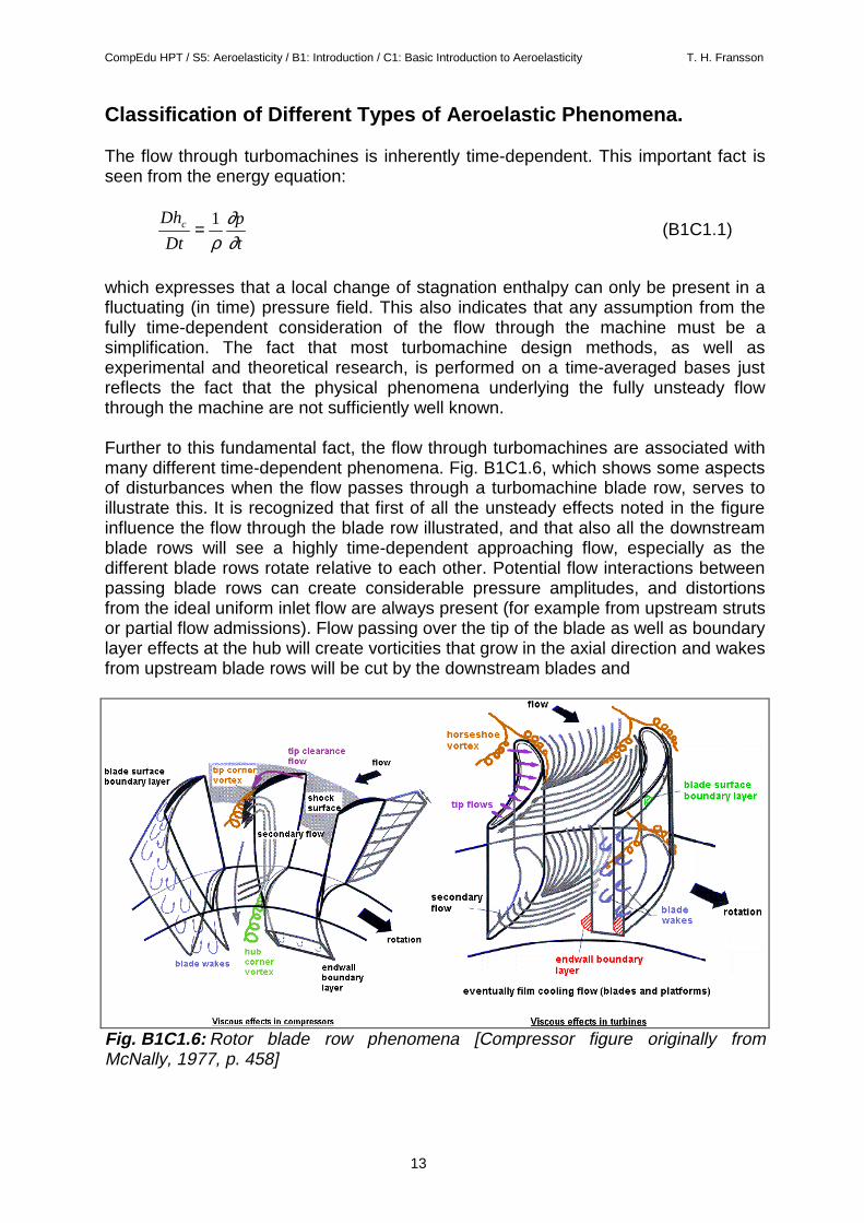
Further to this fundamental fact, the flow through turbomachines are associated withmany different time-dependent phenomena. Fig. B1C1.6, which shows some aspectsof disturbances when the flow passes through a turbomachine blade row, serves toillustrate this. It is recognized that first of all the unsteady effects noted in the figureinfluence the flow through the blade row illustrated, and that also all the downstreamblade rows will see a highly time-dependent approaching flow, especially as thedifferent blade rows rotate relative to each other. Potential flow interactions betweenpassing blade rows can create considerable pressure amplitudes, and distortionsfrom the ideal uniform inlet flow are always present (for example from upstream strutsor partial flow admissions). Flow passing over the tip of the blade as well as boundarylayer effects at the hub will create vorticities that grow in the axial direction and wakesfrom upstream blade rows will be cut by the downstream blades and
Fig. B1C1.6: Rotor blade row phenomena [Compressor figure originally fromMcNally, 1977, p. 458]
CompEdu HPT / S5: Aeroelasticity / B1: Introduction / C1: Basic Introduction to Aeroelasticity T. H. Fransson
14
create highly distorted flow effects. Radial aero- and thermodynamic gradients willpush parts of the flow in certain directions and, in transonic and supersonic flow,highly three-dimensional shock structures will be reflected and interact with the blade(and casing) boundary layers to create unsteady effects on the blade surface. Flowinstabilities can be caused by flow separations at large incidence angles (stall,surge).
All these time-dependent flow phenomena can interact with the blades to createvibrational patterns of different shape and magnitude. On top of all this, thephenomena of "self-excited" blade vibrations, i. e. the interaction of the flow (inprinciple uniform and steady incoming flow) and a structure vibrating out of onereason or another, can considerably complicate the comprehension of these complexflow interactions. Some of the phenomena mentioned are periodic in nature, whereasothers can excite a blade stochastically. Others may be of a discrete nature, underwhich the blade has time to freely damp out the vibration before an eventual newforce again forces the blade into vibration.
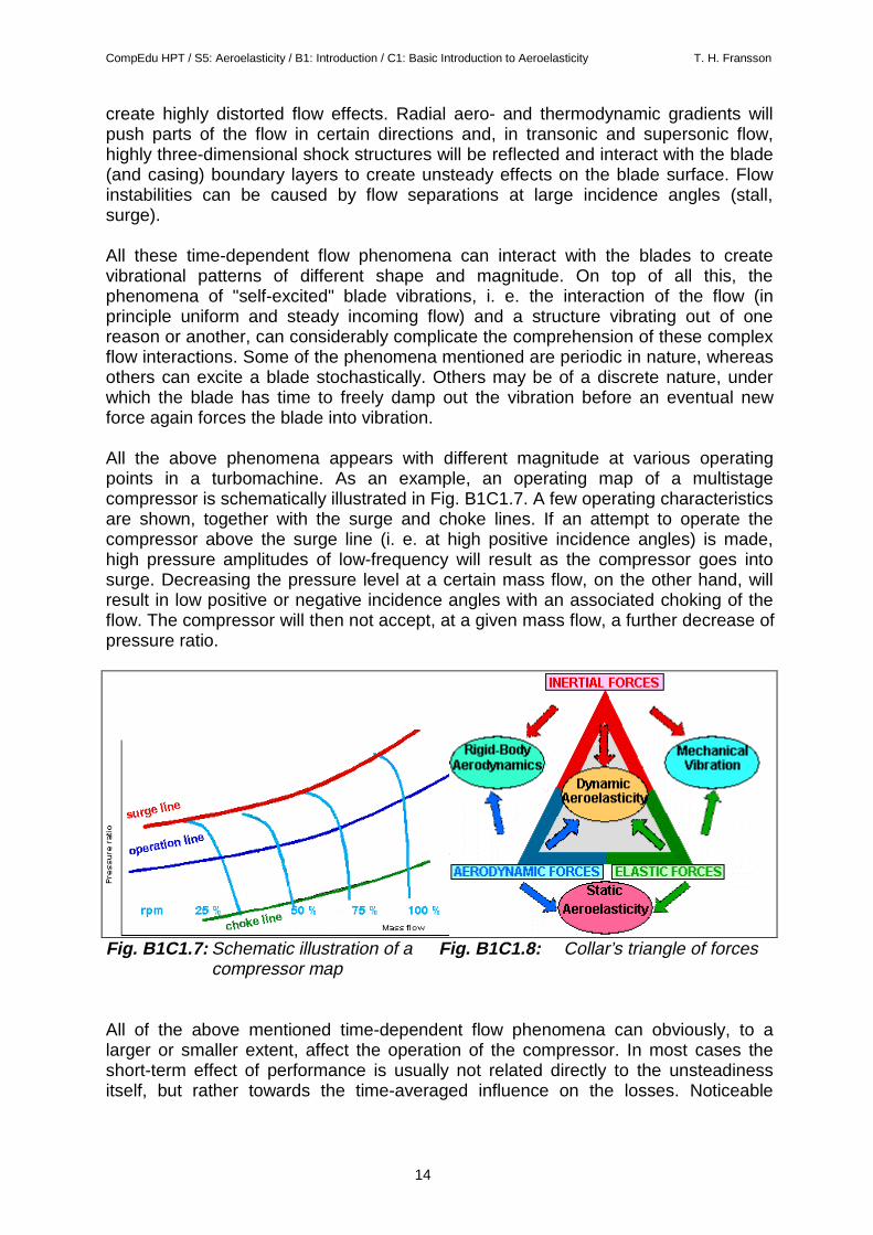
All the above phenomena appears with different magnitude at various operatingpoints in a turbomachine. As an example, an operating map of a multistagecompressor is schematically illustrated in Fig. B1C1.7. A few operating characteristicsare shown, together with the surge and choke lines. If an attempt to operate thecompressor above the surge line (i. e. at high positive incidence angles) is made,high pressure amplitudes of low-frequency will result as the compressor goes intosurge. Decreasing the pressure level at a certain mass flow, on the other hand, willresult in low positive or negative incidence angles with an associated choking of theflow. The compressor will then not accept, at a given mass flow, a further decrease ofpressure ratio.
Fig. B1C1.7: Schematic illustration of a Fig. B1C1.8: Collar’s triangle of forcescompressor map
All of the above mentioned time-dependent flow phenomena can obviously, to alarger or smaller extent, affect the operation of the compressor. In most cases theshort-term effect of performance is usually not related directly to the unsteadinessitself, but rather towards the time-averaged influence on the losses. Noticeable
CompEdu HPT / S5: Aeroelasticity / B1: Introduction / C1: Basic Introduction to Aeroelasticity T. H. Fransson
15
exceptions are cases of large vibrations, either of the rotor or of the blades. Suchvibrations are often of aeroelastic origin.
In Collar’s triangle of forces (Fig. B1C1.8) it is possible to define four major axis,namely the interaction of:
I: Inertial and elastic forcesII: Inertial and aerodynamic forcesIII: Elastic and aerodynamic forcesIV: Aerodynamic, inertial and elastic forces.
The first interdisiplinary technical field above gives an interaction between dynamicsand solid mechanics and can be represented as structural vibrations in the absenceof aerodynamic forces [Dowell et al, 1980, p. 1]. The second treats the connectionbetween the dynamics and aerodynamics and can be represented by stability andcontrol problems. The third and fourth are connected into "static" and "dynamic"aeroelasticity, respectively (see earlier discussion). As mentioned previously thistriangle of forces can be extended to include also thermal forces and automaticguidance and control systems, with the corresponding increase of possiblecombinations.
In the next chapters an overview of the terminology used in the field of aeroelasticityis given. This is done as many terms appear in the literature, each with their distinctmeaning, but as their clear definitions are often not given. It should be pointed outthat this terminology is mostly taken from the field of aeronautics, but that also somephenomena from civil engineering are introduced. It is also important to realize thatthe separation lines between the different terms used are not distinct. The terms areinstead often based on empirical ideas and given because of operating conditions inor close to a specific domain in the operating envelope. As an example the term "stallflutter" can be given. This term is used for flutter in or close to the stall line of acompressor, but strictly it is not necessary that the flow is stalled for this type of flutterto appear. Finally, some terms can have slightly different meanings for differentapplications.