Embed Size (px)
Citation preview

AeroMACS System Requirements Document
Document information Project title Airport Surface Data Link System
Project N° P 15.2.7.
Project Manager ALBERTO MARTINEZ ALBACETE
Deliverable Name AeroMACS System Requirements Document
Deliverable ID T1.1B
Edition 1.0
Please complete the advanced properties of the document
Abstract
This document intends to describe all services and functionalities which shall be supported by
AeroMACS. The SRD includes also some of the AeroMACS RF and performance characteristics.
During the definition phase of the services to be supported by AeroMACS, inputs were taken from
existing FCI documents (COCRv2.0) as well as new inputs provided by the SESAR P15.2.7 WA1 –
RTCA USAS working group and SJU’s AOC data link service characteristics.
Because AeroMACS will be based on WiMAX as defined under IEEE 802.16-2009, this document
follows –wherever applicable - the system requirements and system parameters of Mobile WiMAX as
defined within this standard and its corresponding profiles.
Additional RF characteristics and performance requirements will be defined by ICAO, RTCA,
EUROCAE and ETSI at different stages of the AeroMACS standardisation procedures.

Project ID 00.00.15.2.7. T1.1B - AeroMACS System Requirements Document Edi tion: 00.00.01
2 of 106
Authoring & Approval Prepared By
Name & company Position / Title Date
LOMMAERT LUC / EUROCONTROL WA1 ACTIVITY LEADER 22-11-10
Reviewed By
Name & company Position / Title Date
ANTONIO CORREAS / INDRA CONTRIB/REVIEW 22-11-10
ROBERTO AGRONE / SELEX CONTRIB/REVIEW 22-11-10
STEPHANE FASSETTA / THALES CONTRIB/REVIEW 22-11-10
JAN HAKEGARD / NATMIG CONTRIB/REVIEW 22-11-10
STEPHANE TAMALET / AIRBUS CONTRIB/REVIEW 22-11-10
AURORA SANCHEZ / AENA CONTRIB/REVIEW 22-11-10
MARC LEHMANN / DSNA CONTRIB/REVIEW 22-11-10
LOMMAERT LUC / EUROCONTROL AUTHOR 22-11-10
Approved By
Name & company Position / Title Date
ALBERTO MARTINEZ ALBACETE / INDRA PROJECT MANAGER 22-11-10
ROBERTO AGRONE / SELEX CONTRIBUTORS 22-11-10
STEPHANE FASSETTA / THALES CONTRIBUTORS 22-11-10
JAN HAKEGARD / NATMIG CONTRIBUTORS 22-11-10
STEPHANE TAMALET / AIRBUS CONTRIBUTORS 22-11-10
AURORA SANCHEZ / AENA CONTRIBUTORS 22-11-10
MARC LEHMANN / DSNA CONTRIBUTORS 22-11-10
LOMMAERT LUC / EUROCONTROL AUTHOR 22-11-10
Document History Edition Date Status Author Justification
V0.1 20/01/2010 DRAFT LOMMAERT LUC RTCA INPUT V0.2 09/02/2010 DRAFT LOMMAERT LUC For review to P15.2.7 V0.3 28/04/2010 DRAFT LOMMAERT LUC Includes Live updates from
first review V0.3x 21/06/2010 DRAFT LOMMAERT LUC Input to second review
P15.2.7 V0.4 29/6/2010 DRAFT LOMMAERT LUC Includes Live updates
second review V0.4xsju 06/11/2010 DRAFT LOMMAERT LUC SJU template – inputs 2nd
review and requirement numbering
V1.0final 29/11/2010 FINAL LOMMAERT LUC Comments 3th review / final

Project ID 00.00.15.2.7. T1.1B - AeroMACS System Requirements Document Edi tion: 00.00.01
3 of 106
Table of Contents EXECUTIVE SUMMARY .................................................................................................................................... 8
1 INTRODUCTION .......................................................................................................................................... 9
1.1 PURPOSE OF THE DOCUMENT ................................................................................................................ 9 1.2 INTENDED READERSHIP .......................................................................................................................... 9 1.3 BACKGROUND ......................................................................................................................................... 9 1.4 ACRONYMS AND TERMINOLOGY ........................................................................................................... 10
2 SCOPE OF WORK .................................................................................................................................... 15
2.1 AEROMACS AND SESAR COMMUNICATION PROJECTS ..................................................................... 16 2.2 AEROMACS DOWNLINK UPLINK NOTATION ........................................................................................ 17
3 INPUT REFERENCES TO AEROMACS SRD ...................................................................................... 18
4 OPERATIONAL REQUIREMENTS ........................................................................................................ 20
4.1 SYSTEM OBJECTIVES ........................................................................................................................... 20 4.2 SERVICE SUPPORT ............................................................................................................................... 21 4.3 DATA INPUTS AS PROVIDED BY COCR V2.0 ...................................................................................... 22
4.3.1 Overview of AeroMACS Data ATC Services ......................................................................... 23 4.3.2 Overview of AeroMACS AOC Data Services ......................................................................... 25 4.3.3 Data Traffic Load Requirements .............................................................................................. 25
4.4 OTHER DATA TRAFFIC LOAD REQUIREMENTS ..................................................................................... 27 4.4.1 SWIM Data Load ........................................................................................................................ 28 4.4.2 Collaborative Decision Making (CDM) .................................................................................... 29 4.4.3 Improved Fleet Data Monitoring (CONF) ................................................................................ 29
5 RF REQUIREMENTS ................................................................................................................................ 31
5.1 OVERALL AEROMACS SPECTRUM NEEDS ......................................................................................... 31 5.2 AEROMACS OPERATING FREQUENCY BAND ..................................................................................... 31 5.3 AEROMACS CHANNEL BANDWIDTHS SUPPORTED ............................................................................. 31 5.4 PROPOSED FREQUENCY GRID ............................................................................................................. 32 5.5 IN BAND ADJACENT CHANNEL AEROMACS GUARD BAND ................................................................. 33 5.6 IN BAND PROTECTION CRITERIA AGAINST AS .................................................................................... 33 5.7 IN BAND PROTECTION CRITERIA AGAINST AMT ................................................................................. 33 5.8 TARGETED GUARD BAND FOR OUT OF BAND INTERFERENCE PROTECTION ...................................... 34
5.8.1 AMT protection ........................................................................................................................... 34 5.8.2 MLS Protection ........................................................................................................................... 34 5.8.3 RLAN Protection ......................................................................................................................... 36 5.8.4 Radio Astronomy & Other 5000- Users Protection ............................................................... 36
5.9 IMPACT OF OVERALL RF BANDWIDTH ON CHANNEL AVAILABILITY ...................................................... 37 5.9.1 Channel Availability Reduction Dependencies ...................................................................... 37
5.10 PARTIAL USED SUBCARRIER (PUSC) – WITH ALL SUBCARRIERS ....................................................... 37 5.11 DUPLEXING METHOD: TIME DIVISION DUPLEX .................................................................................... 37 5.12 UL/DL WAVEFORMS CHARACTERISTICS ............................................................................................. 38 5.13 OPERATING TX-RX COVERAGE ........................................................................................................... 38 5.14 THEORETICAL AIRPORT COVERAGE .................................................................................................... 38 5.15 MINIMAL MAXIMUM AIRCRAFT SPEED TO BE COMPENSATED (FOR DOPPLER) ................................... 39 5.16 MINIMAL MAXIMUM VEHICULAR SPEED TO BE COMPENSATED (FOR DOPPLER) ................................ 39 5.17 SUPPORT OF ADVANCED ANTENNA TECHNIQUES ............................................................................... 39
5.17.1 MIMO Support ............................................................................................................................ 39 5.17.2 Adaptive Beam Steering (ABS) Considerations .................................................................... 39
5.18 TRANSMITTER CHARACTERISTICS ........................................................................................................ 40 5.18.1 Downlink HPA Output Power Maxima .................................................................................... 40 5.18.2 Uplink HPA Output Power Maxima ......................................................................................... 40 5.18.3 Maximum Ouput Power Accuracy ........................................................................................... 41 5.18.4 BS Output Power Dynamic Range .......................................................................................... 41 5.18.5 Transmit Output Power Spectral Flatness .............................................................................. 41 5.18.6 Transmitter Spurious Emissions .............................................................................................. 41

Project ID 00.00.15.2.7. T1.1B - AeroMACS System Requirements Document Edi tion: 00.00.01
4 of 106
5.18.7 Transmit Intermodulation .......................................................................................................... 42 5.18.8 BS Transmit Reference Timing Accuracy .............................................................................. 42 5.18.9 WirelessHuman Downlink / Uplink Transmitted Spectral Mask according IEEE802.16-2009 43 5.18.10 Improved transmission mask extended MLS band ........................................................... 44
5.19 MAXIMUM TOLERATED NOISE LEVEL INCREASE AT SATELLITE ANTENNA FOOTPRINT ITU-R M1827 45 5.20 MAXIMUM FLIGHTLEVEL OPERATION ................................................................................................... 45
5.20.1 AeroMAXCS TX Mode .............................................................................................................. 45 5.20.2 AeroMACS RX Mode ................................................................................................................. 45
5.21 RECEIVER CHARACTERISTICS .............................................................................................................. 46 5.21.1 AeroMACS Minimum Receiver Sensitivity ............................................................................. 46 5.21.2 Maximum AeroMACS Receiver Input Signal ......................................................................... 48 5.21.3 AeroMACS Receiver Maximum Tolerable Input Signal........................................................ 48 5.21.4 AeroMACS Minimum Dynamic Range .................................................................................... 48 5.21.5 Receiver Spurious Emissions................................................................................................... 48 5.21.6 Receiver Adjacent Channel Rejection .................................................................................... 49 5.21.7 Receiver Non Adjacent Channel Rejection ............................................................................ 49 5.21.8 Receiver Blocking Characteristics ........................................................................................... 49 5.21.9 Receiver Intermodulation Characteristics ............................................................................... 49 5.21.10 Input System IP3 Requirements .......................................................................................... 49
5.22 AEROMACS TRANSMIT POWER CONTROL ......................................................................................... 49 5.22.1 Open Loop Power Control ........................................................................................................ 50 5.22.2 Closed Loop Power Control ...................................................................................................... 50 5.22.3 TPC Performance ...................................................................................................................... 50
6 AEROMACS FUNCTIONAL REQUIREMENTS ................................................................................... 51
6.1 OPERATING ALTITUDE .......................................................................................................................... 51 6.2 PRIMARY SERVICES .............................................................................................................................. 51 6.3 POSSIBLE SECONDARY SERVICES ....................................................................................................... 51 6.4 SAFETY OF LIFE AND REGULARITY OF FLIGHT SUPPORT .................................................................... 51 6.5 AEROMACS AVAILABILITY FIGURES ................................................................................................... 52 6.6 AEROMACS CONTINUITY FIGURES ..................................................................................................... 52 6.7 AEROMACS INTEGRITY FIGURES ........................................................................................................ 52 6.8 DEGRADATION OF SAFETY ................................................................................................................... 52 6.9 ATN/IPS : IP SUPPORT – ICAO DOC 9896 ....................................................................................... 53 6.10 GENERAL PROVISION OF PRIORITY AND QOS HANDLING .................................................................... 53 6.11 QUALITY OF SERVICE ........................................................................................................................... 53
6.11.1 Extended Real-Time Polling Service ....................................................................................... 53 6.11.2 Real-Time Polling Service ........................................................................................................ 54 6.11.3 Non-real Time Polling Service .................................................................................................. 54 6.11.4 Best Effort Service ..................................................................................................................... 54 6.11.5 Unsolicited Grant Service ......................................................................................................... 54
6.12 QOS CONTROL ..................................................................................................................................... 55 6.13 MULTICAST AND BROADCAST SUPPORT .............................................................................................. 55 6.14 RADIO RESOURCE MANAGEMENT ........................................................................................................ 55
6.14.1 Reporting ..................................................................................................................................... 55 6.14.2 Interference Management ......................................................................................................... 55 6.14.3 Resource Allocation Algorithm ................................................................................................. 55
6.15 SECURITY.............................................................................................................................................. 56 6.15.1 Security requirements................................................................................................................ 57 6.15.2 Operational information security requirements ...................................................................... 57 6.15.3 AeroMACS Security System..................................................................................................... 60 6.15.4 WiMAX security feature shortcomings and potential evolution ........................................... 62
6.16 HANDOVER............................................................................................................................................ 62 6.17 SUPPORT FOR MULTI-HOP RELAY ....................................................................................................... 63 6.18 CO-DEPLOYMENT WITH OTHER NETWORKS ........................................................................................ 63
6.18.1 Co-Existence Scenarios ............................................................................................................ 63 6.19 PERFORMANCE REQUIREMENTS .......................................................................................................... 63
6.19.1 AeroMACS Throughput Estimation (PHY Throughput) ........................................................ 64

Project ID 00.00.15.2.7. T1.1B - AeroMACS System Requirements Document Edi tion: 00.00.01
5 of 106
6.19.2 Theoretical Sector Throughput................................................................................................. 65 6.19.3 DL and UL Theoretical Data Throughput Estimations per User .......................................... 67 6.19.4 Need to re-visit the User data throughputs ............................................................................ 68 6.19.5 Need to revisit Globalstar Interference ................................................................................... 68 6.19.6 Latency ........................................................................................................................................ 69 6.19.7 Handover Interruption Time ...................................................................................................... 70
6.20 AEROMACS SCANNING ....................................................................................................................... 70 6.21 LAYER 3 MOBILITY ................................................................................................................................ 70 6.22 AEROMACS EQUIPMENT COST ........................................................................................................... 71
6.22.1 Ground Infrastructure ................................................................................................................ 71 6.23 INCREMENTAL CAPACITY REQUIREMENTS ........................................................................................... 71 6.24 AEROMACS LEGACY REQUIREMENTS ................................................................................................ 71
6.24.1 Future AeroMACS Developments ........................................................................................... 72 6.24.2 Transition and Backward Compatibility ................................................................................... 73
7 SYNCHRONISATON AND TIMING REQUIREMENTS ....................................................................... 74
7.1 INTRODUCTION...................................................................................................................................... 74 7.1.1 Synchronisation and Timing First Step ................................................................................... 74 7.1.2 Synchronisation and Timing Second Step : Initial Ranging ................................................. 74
7.2 IEEE 802.16-2009 SYNCHRONIZATION HOOKS ................................................................................. 74 7.3 AEROMACS SYNCHRONIZATION REQUIREMENTS .............................................................................. 75
7.3.1 MS Unit ........................................................................................................................................ 75 7.3.2 BS Unit ......................................................................................................................................... 76 7.3.3 Network Synchronization .......................................................................................................... 76
8 CONCEPT OF OPERATIONS AND SCENARIOS .............................................................................. 78
8.1 AIRPORT SERVICE VOLUMES ............................................................................................................... 78 8.2 PROPOSED AIRCRAFT DISTRIBUTION SCENARIOS .............................................................................. 78 8.3 DESCRIPTION OF PRE-DEPARTURE PHASE IN THE APT DOMAIN ....................................................... 78 8.4 DESCRIPTION OF DEPARTURE TAXI IN THE APT DOMAIN ................................................................... 80
ANNEX 1 – AEROMAX SPEED REQUIREMENTS ................................................................................... 80
ANNEX 2 – SERVICES TO BE CONSIDERED .......................................................................................... 85
A2.1 AIRCRAFT .......................................................................................................................................... 85 A2.1.1 Air Traffic Services (ATS) ......................................................................................................... 85 A2.1.2 Aeronautical Operational Control services (AOC services) ................................................. 86
A2.2 SURFACE OPERATION ....................................................................................................................... 87 A2.2.1 Assumptions ............................................................................................................................... 87 A2.2.2 Assumptions related to surface vehicle operation................................................................. 94
ANNEX 3 – (INFORMATIVE FROM SANDRA) .......................................................................................... 99
A.1.1 Assumptions on SWIM Data Characteristics ......................................................................... 99
ANNEX 4 – DATA REQUIREMENTS FAA – ASUS ................................................................................ 101
ANNEX 5 – CHARACTERISATION OF AIRLINE OPERATIONAL COMMUNICATION DATA CHARACTERISTICS ...................................................................................................................................... 102
ANNEX 6 – SECURITY REQUIREMENTS ................................................................................................ 103
A6.1 COCRV2 ........................................................................................................................................ 103 A6.1.1 ATS ............................................................................................................................................ 103 A6.1.2 AOC............................................................................................................................................ 104
A6.2 SURFACE OPERATION ..................................................................................................................... 104 A6.2.1 Point-to-Point services ............................................................................................................ 104 A6.2.2 Ground-to-Air Multicast services ............................................................................................ 105 A6.2.3 Ground-to-Air Broadcast services ......................................................................................... 105
A6.3 AOC SERVICES IDENTIFIED IN SANDRA PROJECT ....................................................................... 105 A6.4 SJU STUDY REGARDING AOC DATALINK DIMENSIONING ............................................................. 105
A6.4.1 Encryption/Confidentiality ....................................................................................................... 105 A6.4.2 Availability/Integrity .................................................................................................................. 106

Project ID 00.00.15.2.7. T1.1B - AeroMACS System Requirements Document Edi tion: 00.00.01
6 of 106

Project ID 00.00.15.2.7. T1.1B - AeroMACS System Requirements Document Edi tion: 00.00.01
7 of 106
List of tables Table 1: AeroMACS prioritisation table ............ .................................................................. 22 Table 2 – COCR defined ATC services for airport ser vice operation .............................. 24 Table 3 – COCR defined AOC services for airport ser vice operation ............................. 25 Table 4 – COCR Phase 2 Addressed Communication Load (kbps) ................................. 26 Table 5 - Protection requirements for MLS ......... ................................................................ 35 Table 6 - Parameters MLS receiver ................. ..................................................................... 35 Table 7 - Transmitter spurious emissions .......... ................................................................ 42 Table 8 - Receiver SNR ...................................................................................................... 47 Table 9 – AeroMACS Receiver Sensitivities : Rss ... .......................................................... 47 Table 10 - General Receiver Spurious Emission Requi rements ...................................... 48 Table 12Theoretical AeroMACS Downlink and Uplink ra w data throughputs for DL/UL
ratio of 2/1 ...................................... .................................................................................. 66 Table 13 Vehicles moving on the airport surface are a ...................................................... 88 Table 14 Distribution of vehicles in airport operat ional volumes .................................... 89 Table 15 AeroMACS subscribers (vehicles) .......... ............................................................. 89 Table 16 Airport Surface Services ................. ...................................................................... 90 Table 17 AeroMACS subscribers: number of vehicles a t a high density airport ........... 94 Table 18 Traffic load for surface operation vehicle s ......................................................... 97 Table 19 Traffic load and data charfacteristics for ATC data ......................................... .. 98
List of figures Figure 1 - Overview of all SESAR communication proj ects ............................................. 17 Figure 2 – Overview of Service Volume Data Channel Requirement Analysis Process 26 Figure 3 Transmit spectral mask as provided by IEEE 802.16-2009 (8.5) ....................... 43 Figure 4 Example of possible antenna configurations to fit different airport areas. .... 64 Figure 5 Ilustration of reference points for the ma ximum data latency .......................... 69

Project ID 00.00.15.2.7. T1.1B - AeroMACS System Requirements Document Edi tion: 00.00.01
8 of 106
Executive summary Under the SESAR Programme activities a new data link (referred to as AeroMACS) is being defined supporting the airport surface applications. This new data link is to be based on the IEEE 802.16-2009 standard. There are two projects in SESAR addressing AeroMACS’s definition: project P15.2.7 and project P9.16. Project P15.2.7 addresses the overall system aspects and focuses on the ground component development whereas project P9.16 focuses on the mobile component. Both packages will need as an input the system requirements for AeroMACS, hence the development of this specification in Work Activity 1. This specification is the result of simultaneously investigating the need for aviation to operate a high data rate link at airport surfaces as well as the requirement for delivering such a link in the most cost effective way (IEEE802.16-2009 based). This specification will be used to specify a dedicated profile (based on the 802.16 standard) covering the aviation requirements. This work will feed the EUROCAE group WG82 that has been formed to define the required aviation specifications. The European activities under the SESAR programme are complemented by activities at the US side. An equivalent to the EUROCAE WG82 group has been set up by RTCA (SC223) and it has been agreed that a jointly developed profile will be drafted.
After both EUROCAE and RTCA have finalised the common AeroMACS profiles, further standardisation of AeroMACS is scheduled to take place under ICAO WG-S as well as the AeroMACS ad hoc working group created by the WMF.

Project ID 00.00.15.2.7. T1.1B - AeroMACS System Requirements Document Edi tion: 00.00.01
9 of 106
1 Introduction
1.1 Purpose of the document The SRD specifies all services and functions the future AeroMACS system should support. This document also defines those parts of the AeroMACS RF requirements and performance requirements which are already know at this stage. Note : within this document, the key words "MUST", "MUST NOT", "REQUIRED", "SHALL", "SHALL NOT", "SHOULD", "SHOULD NOT", "RECOMMENDED", "MAY", and "OPTIONAL" are to be interpreted as described below : 1. MUST this word, or the terms "REQUIRED" or "SHALL ", mean that the definition is an absolute requirement of the specification. 2. MUST NOT this phrase, or the phrase "SHALL NOT ", mean that the definition is an absolute prohibition of the specification. 3. SHOULD this word, or the adjective "RECOMMENDED", mean that there may exist valid reasons in particular circumstances to ignore a particular item, but the full implications must be understood and carefully weighed before choosing a different course. 4. SHOULD NOT this phrase, or the phrase "NOT RECOMMENDED" mean that there may exist valid reasons in particular circumstances when the particular behavior is acceptable or even useful, but the full implications should be understood and the case carefully weighed before implementing any behavior described with this label. 5. MAY this word, or the adjective "OPTIONAL ", mean that an item is truly optional. One vendor may choose to include the item because a particular marketplace requires it or because the vendor feels that it enhances the product while another vendor may omit the same item.
1.2 Intended readership
The AeroMACS system requirements document was developed for technical people and engineers interested and/or involved in the development of AeroMACS BSs or MSs.
The document is also of interest to both ATC and AOC operational staff as it provides detailed information on the different services and functionalities AeroMACS will be supporting.
1.3 Background
Because AeroMACS is based on IEEE 802.16-2009 it is evident that the main background information is to be found in this standard which is available on the IEEE website.
Based on this document the WiMAX Forum (WMF) had developed several profiles of which WMF-T23-001-R015v01 and WMF-T23-002-R015v01 have been selected to form the main baseline of this work.
Other sources for previous background information can be found on Eurocontrol’s website :
http://www.eurocontrol.int/communications/public/st andard_page/AeroMACS.html

Project ID 00.00.15.2.7. T1.1B - AeroMACS System Requirements Document Edi tion: 00.00.01
10 of 106
1.4 Acronyms and Terminology
Term Definition
AAA Authorisation, Authentication and Accounting
AAS Advanced Antenna Systems
ABS Antenna Beam Steering
ACL Arrival Clearance
AeroMACS Aeronautical Mobile Airport Communication System
AES Advance Encryption Standard
AM(R)S Aeronautical Mobile Route Service
AMC Adaptive Modulation and Coding
AMT Aeronautical Mobile Telemetry
AOC Airline Operational Communication
ARQ Automatic Repeat Request
AS Aeronautical Security
ASN Access Service Network
ATM Air Traffic Management
AWGN Additive White Gaussian Noise
BB Base Band
BE Best Effort Service
BER Bit Error Ratio
BPSK Bipolar Phase Shift Keying
BS,BTS Base Station
BW Bandwidth
CC Convolutional Coder
CDM Collaborative Decision Making
CID Connection Identifier
COCR Communications Operational Concept and Requirements

Project ID 00.00.15.2.7. T1.1B - AeroMACS System Requirements Document Edi tion: 00.00.01
11 of 106
Term Definition
CONF Aircraft Configuration Data
CONOPS Concept of Operations
COTS Commercial of the shelf
CP Cyclic Prefix
CRC Cyclic Redundancy Check
CTC Convolutional Turbo Coder
DCL Departure Clearance
DDS Data Distribution Services
DL Downlink
DoS Denial of Service
D-TAXI Departure Taxi
EAP Extensible Authentication Protocol
E-ATMS European Air Traffic Management System
EAS3G European Aviation Security 3G based
EFF Electronic flight folder (bag)
EIRP Effective isotropic Radiated Power
ertPS Extended Real Time Polling Service
EUROCAE European Organisation for Civil Aviation Equipment
EVM Error Vector Magnitude
FCI Future Communication Infrastructure
FEC Forward Error Correction
FFR Fractional Frequency Reuse
FFT Fast Fourier Transform
FMG Frequency Management Group
FTP File Transfer Protocol
GTEK Group Traffic Encryption Key
H-ARQ Hybrid Automatic Repeat Request
HMI Human Machine Interface

Project ID 00.00.15.2.7. T1.1B - AeroMACS System Requirements Document Edi tion: 00.00.01
12 of 106
Term Definition
IE Information Element
IP Internet Protocol
IPsec Internet Protocol security
ITU-R International Telecommunication Union – Radio Communications
LEO Low Earth Orbit
LOS Line of Sight
LRU Line Replaceable unit
MAC Medium Access Control
MBRA Multicast and Broadcast Rekeying Algorithm
MBS Multicast and Broadcast Service
MIMIO Multiple Input Multiple Output
MiTM Man in the Middle
MS Mobile Station
MTU Maximum Transmission Unit
NET Network Management Service
NLOS Non Line of Sight
nrtPS Non Real Time Polling Service
OFDMA Orthogonal Frequency Division Multiple Access
P Project
PDU Packet Data Unit
PENS Pan European Network Services
PER Packet Error Ratio
PHY Physical (layer)
PKM Private Key Management
PN Part Number
PUSC Partial Usage of Subchannels
QAM Quadrature Amplitude Modulation
QoS Quality of Service

Project ID 00.00.15.2.7. T1.1B - AeroMACS System Requirements Document Edi tion: 00.00.01
13 of 106
Term Definition
QPSK Quadrature Phase Shift Keying
RADIUS Remote Dial-in User Service
RF Radio Frequency
RMS Rooth Mean Square
RRM Radio Resource Management
RTCA Radio Technical Commission for Aeronautics
RTD Round Trip Delay
RTG Receive/Transmit transition gap
rtPS Real Time Polling Service
RTT Round Trip Time
RX Receiver
SA Secure Association
SESAR Single European Sky ATM Research Programme
SJU SESAR Joint Undertaking (Agency of the European Commission)
SJU Work Programme The programme which addresses all activities of the SESAR Joint Undertaking Agency.
SESAR Programme The programme which defines the Research and Development activities and Projects for the SJU.
SN Serial Number
SNR Signal to Noise Ratio
SS Subscriber Station
SWIM System Wide Information Management
SWLOAD Software Load (FMS update)
TDD Time Division Duplex
TLS Transport Layer Security
TMA Terminal Control Area
ToD Time of Day
TTG Transmit/Receive transition gap
TX Transmit

Project ID 00.00.15.2.7. T1.1B - AeroMACS System Requirements Document Edi tion: 00.00.01
14 of 106
Term Definition
UDP User Datagram Protocol
UGS Unsollicited Grant Service
UL Uplink
VLAN Virtual Local Aera Network ( IEEE 802.1Q)
WA Work Activity
WMF WiMAX Forum
WS Window Size

Project ID 00.00.15.2.7. T1.1B - AeroMACS System Requirements Document Edi tion: 00.00.01
15 of 106
2 SCOPE OF WORK This document specifies the sets of general, functional, performance and operational requirements that an aeronautical mobile airport surface communications system (AeroMACS) radio should comply with. AeroMACS is based on the existing IEEE 802.16-2009 standard, promoted and certified as WiMAX. Because the WiMAX standard is very complex - given the very large amount of different options and features supported - manufacturers construct their equipment according to specific profiles to provide the intended applications services. Profiles provide details on these subsets of the standard which are considered mandatory or optional and need to be developed in order to be approved by the WiMAX Forum (www.WiMAXforum.org). To be recognised as a profile, support of at least 3 different WiMAX equipment manufacturers is needed. This method ensures that WiMAX base station (BS) and mobile stations (MS) developed by these manufacturers are interoperable. For the AeroMACS, network service subscribers may be both mobile or fixed, and will be referred to as mobile stations (MS) instead of SS.
Previous to the publication of the IEEE802.16-2009 standard, the approved WiMAX Forum (WMF) profiles were split into two parts:
1. System Profiles; specifying subsets of mandatory and optional physical (PHY) and media access control (MAC) layer features.
2. Certification Profiles; specifying the Channel Bandwidth, Operating Frequencies and Duplexing Method.
Since 2009, the WMF profiles as referred to in the IEEE 802.16-2009 document (para. 8.4) have been split into three main parts:
1. COMMON Part
2. TDD Part
3. FDD Part
The TDD part of the WMF profiles does contain today all typical information which was previously found in the Certification profile. The SESAR P15.2.7 WA1 working group has therefore d ecided to replace the system and certification Profiles as mentioned in the P15.2.7 project initial planning (PIR) by a corresponding AeroMACS Profile Analyses document .
Within SESAR P 15.2.7 and as a result of the outcome of the deliverable P15.2.7 WA 1 T1.1A: ‘IEEE 802.16-2009 system analyses for AeroMACS use’, the following WiMAX
Forum™
Mobile System Profile will be analysed:
Draft - T23-001-R010v09-B_MSP
Since early 2006 the WiMAX Forum is working heavily on system profiles which are Release 1 based. However in the future, Release 2 will be made available, providing WiMAX support for 20 MHz bandwidths.

Project ID 00.00.15.2.7. T1.1B - AeroMACS System Requirements Document Edi tion: 00.00.01
16 of 106
As system profiles gradually include more features – resulting in increased performances – some of the parameters provided in this document may have to be updated if more complex parts of the standards are chosen by the aviation community to be incorporated into the AeroMACS new and more advanced profiles.
No technical obstacles - which would make it impossible to use this particular standard for aviation – were found in ref 16. Though the standard investigated may not be optimal in certain aspects (such as maximum data throughput and capacity – which is expected to be much larger in Release 2 due to the increased bandwidth availability) it is considered a good and viable start for making AeroMACS a cost effective solution for aviation.
Notes :
1. From information on IEEE website it is understood that the future Release 2 may not be published but that IEEE may release instead a new standard named IEEE 802.16m covering 20 MHz bandwidth.
2. It is however expected that IEEE 802.16m will be backward compatible with IEEE 802.16-2009.
3. The higher bandwidths of 20 MHz are not targeted by aviation as today’s available bandwidth of 59 MHz , hence limiting the amount of available channels to only two.
2.1 AeroMACS and SESAR communication projects Under SESAR, apart from the airport surface data link, other projects define additional data links for a more general purpose/usage. The picture below provides an overview of all communication related SESAR projects and presents also the relationship of AeroMACS with these projects. From the picture beneath it can be seen that communication services handover may take place between AeroMACS and :
1. P15.2.4 : Future L band Communication System
2. P15.2.6 : Future Satcom Communication System
P15.2.4 apart from the L band system definition addresses also the Multi Link Concept (how the different links will be used to meet the future requirements as well as the network aspects including Handovers, Mobility and support of required quality of service). In the future, when AeroMACS will be implemented, the AeroMACS ground infrastructure will be integrated in the overall ground network service considered in other SESAR projects such as P15.2.10 (PENS), WP 14 (SWIM) and eventually in WP 6 (airport operations).

Project ID 00.00.15.2.7. T1.1B - AeroMACS System Requirements Document Edi tion: 00.00.01
17 of 106
Figure 1 - Overview of all SESAR communication proj ects
2.2 AeroMACS Downlink Uplink Notation Important notice on the use of DOWNLINK and UPLINK:
Throughout this document the downlink means the tra nsmission from BS towards MS (BS���� MS) while uplink means the transmission from MS t oward BS (MS ���� BS) These definitions are the ones which are considered as co mmonly accepted within communication standards. However it should be noted that within the COCR v.2 .0 (as well as the operational requirements part of this document) the operational use of a data link is considered where downlink means down linking the data towards the ground and uplink means sending data from ground towards the aircraft. These definitions are the ones which are considered as commonly accepted during aviation operational discussions .

Project ID 00.00.15.2.7. T1.1B - AeroMACS System Requirements Document Edi tion: 00.00.01
18 of 106
3 Input References to AeroMACS SRD Several documents have been used as input for delivering the AeroMACS system Requirements:
1. COCR v.2 : ‘Communications Operating Concept and Requirements for the Future Radio System’.
2. ‘IEEE 802.16-e aero: SYSTEM PROFILE FOR FCI’S AIRPORT SURFACE OPERATION’ v1.3.
3. IEEE 802.16-2009 : Part 16: Air Interface for Broadband Wireless Access Systems
4. NASA/CR – 2007-214456 : Wireless Channel Characterisation in the 5 GHz Microwave Landing System Extension Band for Airport Surface Areas. ( David Matolak Ohio University).
5. Mobile WiMAX : A technical Overview and Performance Evaluation ( Mehedi Hasan) (WiMAX Forum)
6. Mobile WiMAX : Part II : A comparative Analysis May 2006 (WiMAX Forum)
7. Mobile WiMAX Throughput Measurements using R&SCMW270 ; Steffen Heuel and Heinz Mellein.
8. ITU-R Annex 6 to Doc 8B/559-E 23 November 2006
9. Mitre MTR090485 : ANLE – MSS band sharing report.
10. WiMAX ForumTM Mobile System Profile Specification Release 1.5 TDD Specific Part WMF-T23-002-R015v01
11. WiMAX ForumTM Mobile System Profile Specification Release 1.5 Common Part WMF-T23-001-R015v01
12. Future Communications Infrastructure - Technology Investigations Evaluation ScenariosVersion 1.0
13. UMTS / FDD operating at C-band : Physical Layer Validation Report v1.0 Lommaert Luc 7 June 2007
14. ITU-R Document 8B/622-E : MLS protection criteria for determining the protection distances between transmitters operating in the aeronautical mobile service (AMS) to support telemetry for flight testing and MLS ground stations operating in the aeronautical radio navigation service
15. ITU-R M1827 : “Technical and operational requirements for stations of the aeronautical mobile (R) service (AM(R)S) limited to surface application at airports and for stations of the aeronautical mobile service (AMS) limited to aeronautical security (AS) applications in the 5091-5150 MHz”
16. WA1 T1.1A : IEEE 802.16-2009 system analyses for AeroMACS use,
17. ACP-WGW03-IP04-US C-Band Airport Comm System Progress Update.
18. ED 78A/DO-264: Guidelines for approval of provision and use of Air Traffic Services supported by data communication.
19. ETSI EN 302 544-1 V1.1.2 Broadband Data Transmission system operating in the 2500 MHz to 2690 MHz frequency band Part 1 TDD Base Stations.
20. ETSI EN 302 623 V1.1.1 Broadband Wireless Access Systems (BWA) in the 3400 MHz to 3800 MHz frequency band ; Mobile Terminal Stations

Project ID 00.00.15.2.7. T1.1B - AeroMACS System Requirements Document Edi tion: 00.00.01
19 of 106
21. CEPT/ERC/REC 74-01 Unwanted Emissions in the Spurious Domain.
22. NASA GRC 802-16 Initial Security Assessment Final report 22-december-2009
23. DFS e-mail Armin Schlereth ( annex)
24. Fundamentals of WiMAX / Andrews, Ghosh, Muhamed – Prentice Hall ISNN 0-13-222552-2.
25. ITU-R Resolution 418 ( WRC-07) : Use of the band 5091-5250 by the aeronautical mobile service for telemetry applications.
26. Draft - T23-001-R010v09-B_MSP

Project ID 00.00.15.2.7. T1.1B - AeroMACS System Requirements Document Edi tion: 00.00.01
20 of 106
4 Operational Requirements
4.1 System Objectives
R-OPS-SYS-01. AeroMACS system shall comply to the ITU-R spectrum requirements for AM(R)S as specified under Annex 1 Resolution 418 of WRC- 07 Annex
R-OPS-SYS-02. AeroMACS system shall comply with the ITU-R M1827 requirements
R-OPS-SYS-03. In Europe AeroMACS shall support only mobile services
R-OPS-SYS-04. In Europe AeroMACS shall support only ATC and AOC services supporting safety and regularity of flight.
R-OPS-SYS-05. AeroMACS shall support ATC and AOC services which are encountered at an airport surface level.
R-OPS-SYS-06. AeroMACS shall meet availability figures as required by the safety and regularity of flight ATM services it will support.
R-OPS-SYS-07. AeroMACS shall operate with mobile speeds of up to 50 knots (see ref 23).
R-OPS-SYS-08. AeroMACS shall meet integrity figures as required by the safety and regularity of flight services it will support.
R-OPS-SYS-09. AeroMACS shall meet continuity figures as required by the safety and regularity of flight services it will support.
R-OPS-SYS-10. AeroMACS shall be designed to provide the foreseen ATC and AOC services 24h on 24h.
R-OPS-SYS-11. AeroMACS shall be designed to support the Internet Protocol.
R-OPS-SYS-12. AeroMACS shall be designed as a wireless connection providing seamless extension to Pan European Network Services (PENS) as defined under SESAR P15.2.10.
R-OPS-SYS-13. AeroMACS shall be designed to support the extension to the aircraft of the SWIM architecture as defined under SESAR WP14.
R-OPS-SYS-14. AeroMACS shall be designed to be single failure tolerant.
R-OPS-SYS-15. The total failure of an AeroMACS BS or BS sector shall only reduce temporarily the availability of the BS (BS sector) coverage area and shall have no impact on the performance of other sectors.
R-OPS-SYS-16. AeroMACS system design shall be compliant with the safety regulations for ATM systems.
R-OPS-SYS-17. AeroMACS shall implement sufficient system monitoring and control features in order to verify the requested operational availability figures and network performance.
R-OPS-SYS-18. AeroMACS shall implement Time of Day (ToD) time event logging conforming to RFC 868.
R-OPS-SYS-19. AeroMACS handover procedure shall be compatible with the operational requirement in terms of continuity of service and shall thus not provoke any ATC service interruption.
R-OPS-SYS-20. AeroMACS handover shall not provoke any ATC service breakdown.
R-OPS-SYS-21. AeroMACS handover shall not provoke any AOC service interruption.

Project ID 00.00.15.2.7. T1.1B - AeroMACS System Requirements Document Edi tion: 00.00.01
21 of 106
R-OPS-SYS-22. AeroMACS handover shall not provoke any AOC service breakdown.
R-OPS-SYS-23. AeroMACS shall authenticate all users when attaching to the AeroMACS access network.
R-OPS-SYS-24. AeroMACS shall not support ToD authentication.
R-OPS-SYS-25. AeroMACS shall support authorization when a user attaches to the AeroMACS access network.
R-OPS-SYS-26. In the future, the AeroMACS network shall support handover to the future L band and Satcom aeronautical radios.
However, under the P15.2.7 and P9.16 projects, handover to other radio systems than AeroMACS will not be implemented as the L1 (PHY) and L2 (MAC) layers of these future radio systems are not yet defined.
4.14.2Service Support
Under SESAR P15.2.7 and P9.16, it was decided to assess as much as possible the limitations of the AeroMACS system. Consequently, we are not going to restrict the scope of the services to be considered in these Research projects.
The following have been derived from the information related to the services provided:
• In COCRv2,
• By the SANDRA (R&D) project; refinement of the AOC service requirements,
• SJU AOC needs study,
• SJU Com Study.
R-OPS-SER-01. Under SESAR P15.2.7 and P 9.16 AeroMACS shall support all mobile ATC services related to safety and regularity of flight as encountered at airport surface level.
R-OPS-SER-02. Under SESAR P15.2.7 and P 9.16 AeroMACS shall support all mobile AOC services related to safety and regularity of flight as encountered at airport surface level.
R-OPS-SER-03. AeroMACS shall support the necessary Network Management services (NET) as required by the supported safety of life and flight regularity services.
R-OPS-SER-04. AeroMACS shall support airport vehicles services related to safety and regularity of flight as encountered at airport surface level.
R-OPS-SER-05. In Europe AeroMACS shall support data services related to safety and regularity of flight as encountered at airport surface level.
R-OPS-SER-06. AeroMACS shall support ground to air broadcast services.
R-OPS-SER-07. AeroMACS shall support ground to air multicast services.
R-OPS-SER-08. AeroMACS shall support point to point data communication services.
R-OPS-SER-09. AeroMACS shall support Voice over IP services.
R-OPS-SER-10. Under SESAR P15.2.7 and P9.16 VOIP shall not be supported.

Project ID 00.00.15.2.7. T1.1B - AeroMACS System Requirements Document Edi tion: 00.00.01
22 of 106
R-OPS-SER-11. AeroMACS shall allow the prioritisation between NET, ATC and AOC services.
R-OPS-SER-12. AeroMACS shall allocate the highest priority to NET services.
R-OPS-SER-13. AeroMACS shall allocate the second highest priority to ATC services.
R-OPS-SER-14. AeroMACS shall support prioritisation for ATC services.
R-OPS-SER-15. AeroMACS shall support 3 different ATC services prioritisation levels.
R-OPS-SER-16. AeroMACS shall support 2 different AOC service prioritisation levels.
R-OPS-SER-17. AeroMACS shall support AOC service prioritisation within AOC services
R-OPS-SER-18. AeroMACS service prioritization levels shall be implemented according to the outcome of an appropriate workgroup to be established for these purposes.
R-OPS-SER-19. AeroMACS service prioritization levels shall not be modifiable by local ATC ANSP’s or AOC centres.
Note: AeroMACS will allow the prioritisation between NET, ATS, AOC services and surface operation services.
The following prioritisation levels are defined in the table below:
Subscribers Priority 1 (highest)
Priority 2 Priority 3 Priority 4 Priority 5 Priority 6
Aircraft NET services
ATS 1 ATS 2 ATS 3 AOC 1 AOC 2
Surface vehicles
NET services
ATS2 ATS 3 Surface operation
Table 1: AeroMACS prioritisation table
4.24.3Data Inputs as Provided by COCR V2.0 Under Action Plan AP17, EUROCONTROL and FEDERAL AVIATION ADMINISTRATION (FAA) have developed a Communication Operational Concept and Requirements for future radio systems (starting 2020 onwards) or COCR. COCR V2.0 has analysed the future data requirement needs (data content, data throughputs and latencies) for different service volumes, one being the airport surface level. COCR had as purpose to make an initial estimation of the various data loads needed in the future for both air traffic control (ATC) and airline operational communications (AOC) data. Though information contained in COCR is the best source available today on FCI data loads, more detailed work on various applications and services will be worked out at a later stage by SESAR and NextGen. Projects developed jointly under SESAR/Nextgen such as system wide information management (SWIM) may lead to an improved data load estimation and/or additional data characteristics. Note: COCR has defined a 2 different phase deployment scenario : The first phase (Phase 1) is based on existing or emerging data communication services. Initial steps of this phase are starting in some regions of the world now. Phase 2 introduces new data communication services that replace or supplement those in Phase 1 as data communications become the standard method of air-ground

Project ID 00.00.15.2.7. T1.1B - AeroMACS System Requirements Document Edi tion: 00.00.01
23 of 106
communication and supports increased automation in the aircraft and on the ground. In Phase 2, the data communications system becomes integral to the provision of ATM. Within SESAR P 15.2.7 we consider only Phase 2 as phase 2 has the most stringent requirements on data in terms of throughput and latency. Note: The SESAR projects address the definition of the AeroMACS data link system. For the purposes of the definition, all future airport surface services are considered in the dimensioning of the AeroMACS system. However, as implementation of airport surface services is not addressed in this context, this does not imply that the considered services can only be (or will have to be) implemented over AeroMACS.
4.2.14.3.1Overview of AeroMACS Data ATC Services The following table which has been extracted from COCR V2.0 gives an overview of all ATC messages which are encountered in the APT service volume. The table provides besides the message name also information on the number of instances each message will occur.

Project ID 00.00.15.2.7. T1.1B - AeroMACS System Requirements Document Edi tion: 00.00.01
24 of 106
Service Type1
APT I II
ACL X X Type I&II: 1 (in ground position), both departure and arrival
ACM X X 3 per domain (1 in each position), both departure and arrival
AMC** (per ATSU)
X X 1 per week per ATSU
COTRAC2 - X 1 (in ramp position) departure only
D-ALERT X X 1 per aircraft per year
D-ATIS (Departure) X X 1 (in ramp position), departure only for 30% of aircraft
DCL X - 1 (in ramp position), departure only
D-FLUP X X 1 (in ramp position), departure only
DLL X X 1 (in ramp position), departure only
D-OTIS X X 1 (in ramp position), departure only for 70% of aircraft
D-RVR X X 1 (in ramp position), 30% of the time, departure only
D-SIG X X 1 (in ramp position), departure only
D-SIGMET X X 1 (in ramp position), 30% of the time, departure only
D-TAXI X X 1 (in ground position), departure and arrival
FLIPCY X - 1 (in ramp position), departure only
FLIPINT X X 1 (in ramp position), departure only
PAIRAPP SURV - X Once every 2 s
PPD X X 1 (in ramp position), departure only
SURV X X Once every 2 s
TIS-B - - -
URCO - X 1 per aircraft per year
WAKE X X Once every 2 s
Table 2 – COCR defined ATC services for airport ser vice operation
Note : AeroMACS will not support WAKE services as indicated in ref 1. and table above as AeroMACS will only operate at ground surface level where no WAKE turbulence is encountered. 1 Type I aircraft have basic data link equipage. Type II aircraft have COTRAC equipage. An ‘X’ in the column indicates the
instances are applicable to that type of aircraft. A ‘-‘ in the column indicates the instances are not applicable for that type of aircraft.
2 For Type II aircraft, 75% of the COTRAC exchanges are WILCO’d and 25% of them require a negotiation. When COTRAC is not available, aircraft will use Phase 1 services.

Project ID 00.00.15.2.7. T1.1B - AeroMACS System Requirements Document Edi tion: 00.00.01
25 of 106
4.2.24.3.2Overview of AeroMACS AOC Data Services
Service
APT AOCDLL 1 per ramp dep
CABINLOG 1 per ramp arr
FLTLOG 1 per ramp arr
FLTPLAN 1 per ramp dep
LOADSHT 2 per ramp dep
NOTAM 1 per ramp dep
OOOI 1 ramp dep 1 rwy takeoff 1 rwy landing
1 ramp arr SWLOAD 1 per ramp dep
TECHLOG 1 per ramp dep
UPLIB 1 per ramp dep
WXGRAPH 1 per ramp dep
WXRT Takeoff: 1 rpt every 6s
WXTEXT 1 per ramp dep
Table 3 – COCR defined AOC services for airport ser vice operation
Note : It has been accepted by all parties involved in the development of the COCR that AOC data requirements have not been fully developed due to lack of responses of AOC partners involved. Hence within P15.2.7 and USAS data requirement effort will be concentrated on AOC services and AOC data characteristics.
4.2.34.3.3Data Traffic Load Requirements The reader should notice that COCR provides an estimation of AOC traffic which was not obtained through extensive queries of airlines, given the limited timeframe available for producing the COCR. Hence the numbers for AOC traffic should be taken as very rough first estimations. COCR V2.0 takes stock of all ATC and AOC messages and provides individual packet sizes, latency requirements and message instantiation per service volume. However in order to come to the combined data load FAA had developed a queuing model where all messages have been prioritised and where care is taken of the instantiations of each message. Therefore the total data rate can not be traced back by simple additions and spreading instantiations over time. An overview of this process or queuing model is given in the drawing below.

Project ID 00.00.15.2.7. T1.1B - AeroMACS System Requirements Document Edi tion: 00.00.01
26 of 106
Figure 2 – Overview of Service Volume Data Channel Requirement Analysis Process
4.2.3.14.3.3.1Total Addressed Communication Data Traffic Load Table 3 provides the overall average addressed communication data loads for both a high density (2304 Daily operations) and low density (64 Daily Operations) Airport Service volumes.
PHASE 2 APT SV
HD LD
Separate ATS
UL 30 20
DL 30 30
UL&DL 40 30
Separate AOC
UL 150 40
DL 7 2
UL&DL 200 40
Combined ATS&AOC
UL 150 40
DL 30 30
UL&DL 200 40
Table 4 – COCR Phase 2 Addressed Communication Load (kbps)
As can be seen from the first columns the overall (combined up and downlink) expected average data load is not larger than 200 kbps . R-OPS-DAT-01. AeroMACS shall support at least the total addressed data load as specified
within CoCR v2.0
R-OPS-DAT-02. AeroMACS shall handle all ATS applications with the highest priority and corresponding QoS parameters.
4.2.3.24.3.3.2Addressed Communication Data Latency
Service volume NetworkManagement, ATS andAOC service instancesper aircraft
PIAC per service volume
Service volume T(95)
-
Required Data ThroughputWithout Subnetwork Overhead for Service Volume
Inputs(Problem definition)
Process(for solving the problem)
Output(Desired result)
Flight duration in servicevolume
Service volume NetworkManagement, ATS andAOC service instancesper aircraft
PIAC per service volume
Service volume T(95)
Required Data ThroughputWithout Subnetwork Overhead for Service Volume
Inputs(Problem definition)
Process(for solving the problem)
Output(Desired result)
Flight duration in servicevolume
Priority-Queuing Analysis Using CAT software

Project ID 00.00.15.2.7. T1.1B - AeroMACS System Requirements Document Edi tion: 00.00.01
27 of 106
One way latency has been defined per individual service. In COCR the major services - with respective indicative expected latencies indicated between brackets - are DCL (9,2s), D-TAXI (5,7s), ACL (3s). Most of the AOC data have indicative expected latencies between 30 and 60 s. R-OPS-DAT-03. AeroMACS shall respect the required latencies for addressed data
communications as provided in COCR v2.0 table 5-8 and 5-9 for ATC and AOC messages.
Note : latency figures are always quoted for P.95 – meaning that in 95% of the message transfers the quoted latency figures are met.
4.2.3.34.3.3.3Total Broadcast Information Transfer Rate Table 6-35 from COCR v2.0 indicates that for Phase 2 the total expected Broadcast Information Transfer Rate for airport services is equal to 239 kbps – irrespective of the service volume’s density.
R-OPS-DAT-04. AeroMACS shall support the minimum broadcast data load requirements as specified within CoCR v2.0 .
R-OPS-DAT-05. AeroMACS shall handle all Broadcast ATS applications with the highest priority and corresponding QoS parameters as specified within CoCR v2.0.
4.2.3.44.3.3.4Broadcast Information Data Latency Table 6-35 also indicated the shortest indicative expected latency for broadcast data as 0,4s. R-OPS-DAT-06. AeroMACS shall support the minimum maximum broadcast data latencies as
specified in the CoCRv2.0 table 5-8.
4.2.3.54.3.3.5Overall Communication Data Traffic Load A combined (addressed and broadcast) data traffic load of < 450 kbps is expected to be needed at airport surface level by COCR v2.0.
R-OPS-DAT-07. AeroMACS shall support at least these minimum data load with different priorities as specified in the COCRv2.0.
4.34.4Other Data Traffic Load Requirements COCRv2 provide a good overview of the ATS to be supported by the AeroMACS and the related requirements. However, regarding the AOC services, the needs identified in COCRv2 could be underestimated. AOC needs were refined in the SANDRA project and in the SJU Study addressing such topic. These inputs have been considered to define the present System Requirements,

Project ID 00.00.15.2.7. T1.1B - AeroMACS System Requirements Document Edi tion: 00.00.01
28 of 106
nevertheless, to get a good order of magnitude of the required bandwidth, it is necessary to implement a queuing model taking into account notably:
• The number of mobiles to be served, • The characterization of the traffic flows (e.g. prioritisation, message size…) • The operational sequence of the instances of the services.
Then the capacity of the system will have to be assessed against the latency requirements of the different type of traffic flows. This activity will be performed in WA02 of P15.2.7 in collaboration with Sandra project. Moreover, in P15.2.7 AeroMACS capacity is also assessed to support- in parallel to the traffic with Aircraft - communications with Surface Vehicles. The details of this additional type of traffic are presented in ANNEX 2. The following additional sources have been used in order to update the COCR data requirements :
1. Individual stand alone inputs as received during the development of SESAR P15.2.7 WA1 and provided by FAA and EUROCONTROL and other partners such as SANDRA. They all reside under paragraph 4.4 and are not part of the Annexes
2. Inputs developed under P15.2.7 in a dedicated subtask led by DSNA. Results are located in Annex 2.
3. Inputs received from RTCA USAS forum. Reports also located in Annex 3. 4. Inputs received from SJU ‘ Characterisation of Airline Operational Communication data
characteristics. Details are found in respective document link as indicated in Annex 4. .
4.3.14.4.1SWIM Data Load SWIM is handled within SESAR P14 and is considered an architecture for ATM data distribution. The extension of SWIM to the aircraft is not clearly defined. It could be based on some middleware equivalent or similar to OMG’s data distribution services (DDS v1.3) creating a publish / subscribe or request/reply relationship between client and server. SWIM system and related studies will be carried out in the near future by different Work Packages of the SESAR programme. Namely, the principal SWIM related work packages will be WP8 and WP14 which will respectively define the data/services to be exchange among the different systems that are involved in the ATM domain and the technical middleware infrastructure that will enable those data/services to be seamlessly exchanged. Anyway, at the current stage, still many uncertainty is present with respect to the architecture of the SWIM system when considering the involvement of the Airborne side both for what concerns the data/services to be exchanged/supported, and for the actual SWIM airborne architecture (whose definition also involves WP9 projects 9. Hence it is difficult to estimate the impact of SWIM onto the overall data load. However, SWIM data exchanges will mainly be based on the services/applications identified in COCRv2. In particular, considering SESAR definition phase it is possible to assume that the data that will have to be shared will be:
1. Meteo information
2. Flight (plan) information
3. Aeronautical information
As an example, in 9.19 SESAR Project, the following ATM services have been identified as good candidates to be implemented using the SWIM architecture. There are two groups of SWIM A-G candidate services: information publishing and information retrieval. The information publishing is

Project ID 00.00.15.2.7. T1.1B - AeroMACS System Requirements Document Edi tion: 00.00.01
29 of 106
used to publish airborne information to ground SWIM that further distributes the information to ground ATM systems. NOTE: The lists below present only the services identified by P9.19 and which can be supported by AeroMACS according to its technical and institutional limitations. SWIM Air to Ground Information Publishing: PPD, WXRT, FLIPINT, D-ALERT, OOOI, SURV/ADS-C, D-TAXI, MAINTRT.
SWIM Air from Ground Information retrieval: D-ATIS, NOTAM, D-SIG, VOLMET, SIGMET, D-RVR, WXTEXT, WXGRAPH, TIS-B, D-FLUP, FLTPLAN, and LOADSHT.
Moreover, because the communication between aircraft and ground systems provides a limited and costly bandwidth, the preferred model is to optimise data formats and protocols on the air interface, and to implement a gateway on ground, in charge of data and protocol conversion between the Air interface SWIM and the ground SWIM. This gateway would play the SWIM manager role for the other ground elements, if required. It is identified as the AGDLGMS in the WP14.
Consequently, it is proposed in P15.2.7 (especially in WA02): • to consider the size of the messages as presented COCRv2 as this document can provide a
reasonable order of magnitude, • check against “Information publishing” and “Information retrieval” procedures, the sequence of
messages related to “SWIM” services presented in COCRV2.
4.3.24.4.2Collaborative Decision Making (CDM) CDM is the process by which agreements are met and decisions are taken considering the preferences and needs of all involved partners. SWIM is the technical enabler of information sharing required for the CDM process. Consequently, the data requirements related to SWIM and thus to the applications and services identified in COCRv2 cover the great majority of the data requirements related to the CDM process. NOTE: The US has made a preliminary data load estimation for CDM services. The total data rate needed in order to support CDM is estimated to be 1Mbps . However, this data throughput is related to fixed applications which can not be supported by AeroMACS with regards to the ITU spectrum allocation.
4.3.34.4.3Improved Fleet Data Monitoring (CONF) R-OPS-ODA-01. Improved fleet data monitoring shall be obtained by :
1. enhancing monitoring data base with the type and the software version of equipments
(Statistics about interoperability)
2. making more information available on the Bite (troubleshooting report )
Avionic database: Used to obtain more information about the avionic equipment identification on board (PN and SN). The information about the avionic LRU identification should improve the existing

Project ID 00.00.15.2.7. T1.1B - AeroMACS System Requirements Document Edi tion: 00.00.01
30 of 106
PRISME data base. It shall be possible to update this database systematically and automatically one or two times per year. Bite information: To have access to the Bite information. The knowledge of the number of failure occurrences during the flight should improve significantly the process of detection of anomalies mainly in the case of partial non detected anomalies. Fleet Monitoring data load estimation per aircraft: Equipment characterization by the part number : 12 characters or 50 bits Software level characterization: 12 characters or 50 bits Trouble shooting characterization 8 bits per LRU Total = 108 bits or 27 bytes Total estimated data for 20 LRU: 2160 bits or 540 bytes per aircraft.
These estimations have been worked out by Eurocontrol’s Surveillance department with the main purpose to detect, trace and solve existing MODE-S extended squitter SPORADIC failures.
More elaborated and generalized inputs for CONF have been included in Annex 2.

Project ID 00.00.15.2.7. T1.1B - AeroMACS System Requirements Document Edi tion: 00.00.01
31 of 106
5 RF Requirements Although strictly speaking SESAR P 15.2.7 covers only the AeroMACS ground infrastructure and P9.16 covers the airborne or MS part some of the RF parameters have been bundled in order to have a better overview of the global RF parameters applicable. The following RF characteristics have been grouped together and shall be applicable to AeroMACS.
5.1 Overall AeroMACS Spectrum Needs During the WRC07 conference – and in order to make the extended MLS band available to communications - the total estimated bandwidth needed for future airport surface communication system was defined as 60 MHz.
During the WRC07 a total of 59 MHz has been granted to AeroMACS and AMT.
5.2 AeroMACS Operating Frequency Band
R-RFR-AOF-01. AeroMACS shall operate within the extended MLS band between 5091 and 5150 MHz co-allocated for aeronautical mobile route service [AM(R)S] at the World Radio Communications Conference (WRC) in 2007.
This international allocation is currently limited to communications with vehicles in contact with the airport surface and for communications services directly supporting or impacting safety and regularity of flight. Note : The exact spectrum usage shall be determined at a later stage - as the US intends to operate split spectrum for ATC and AOC services - and after all interference tests have been finalised R-RFR-AOF-02. AeroMACS final channelization parameters (channel centre frequencies and
frequency grid) shall be defined once the necessary capacity estimations and interference testing have been performed.
5.3 AeroMACS Channel Bandwidths Supported Under IEEE 802.16-2009 several bandwidths (Scalable Orthogonal Frequency Division Multiple Acces (S-OFDMA)) are foreseen in order to support the requested data throughput and capacity requirements. IEEE 802.16-2009 supports 1,25 MHz (128 point Fast Fourier Transform), – 5MHz (512 point FFT) and 10 MHz (1024 point FFT). The standard also supports 20 MHz (2048 point FFT) but no 20MHz profile has been made available today. Note: the 1,25 MHz bandwidth shall not be considered as no WiMAX Forum Profile exists for this bandwidth. R-RFR-ACB-01. AeroMACS shall support 5 MHz (512 point FFT) channel BW.
Note : AeroMACS shall support 10 MHz (1024 FFT) channel BW only in case the need for this bandwidth has been confirmed by the necessary studies.

Project ID 00.00.15.2.7. T1.1B - AeroMACS System Requirements Document Edi tion: 00.00.01
32 of 106
5.4 Proposed Frequency Grid The lower part of the MLS band between 5000 and 5030 MHz is not currently approved by ITU-R for communications. However, it is possible that this issue maybe re-discussed in a future WRC. It has been agreed between the RTCA and EUROCAE AeroMACS groups to propose a channel grid covering the whole 5000-5150 MHz bandwidth. This would prevent costly avionics equipment refurbishments in case more spectrum would become available in the future. R-RFR-TRC-01. AeroMACS frequency grid shall cover the whole 5000-5150 MHz band.
However the proposed frequency grid today would be optimized for the 5091-5150 MHz band which has been opened up already for aviation communication. Between 5000 and 5030 and the ITU-R approved spectrum part of 5091 and 5150 MHz a 250 kHz frequency grid is proposed for AeroMACS. This 250kHz step size will allow AeroMACS to gracefully move away from any interference source such as MLS, AMT, Military users located in extended MLS band. The preferred set of centre frequencies are specified as : R-RFR-TRC-02. For 5 MHz channelization AeroMACS shall use centre frequencies as defined
by the formula : 5002,5 + n*0.25 for n = {0…100 and 364…580} in MHz.
R-RFR-TRC-03. For 5 MHz channelization AeroMACS the preferred set of centre frequencies shall be defined by the formula : 5005 + n*5 for n = {0…4 and 18…28}
Note1 : In case 10 MHz channelization would be needed AeroMACS shall use a centre frequency as defined by the formula : 5005 + n*0.25 for n = {0…80 and 364…570} in MHz. Note 2 : In case 10 MHz channelization would be needed AeroMACS the preferred set of centre frequencies shall be defined by the formula : 5005 +n*10 for n={0…2 and 9…14} R-RFR-TRC-04. The common AeroMACS reference frequency to be used in order to
determine AeroMACSs 250 KHz centre grid shall be 5145 MHz.
R-RFR-TRC-05. AeroMACS MS shall be tunable with 250 kHz steps with respect to the reference frequency.
R-RFR-TRC-06. AeroMACS BS shall be tunable with 250 kHz steps with respect to the reference frequency.
REMARK : NOT all services as defined today may be c onsidered as safety of life and regularity of flight (e.g. Movie downloads). An interesting ev olution could be to expand AeroMACS tuning capabilities in order to be able to operate AeroMACS also in the lower part of UNNI band. In case A/C would be fitted with double AeroMACS ra dios (redundancy) one could be tuned to 5300 + UNNI band for all other commercial services.

Project ID 00.00.15.2.7. T1.1B - AeroMACS System Requirements Document Edi tion: 00.00.01
33 of 106
5.5 In Band Adjacent Channel AeroMACS Guard Band
R-RFR-IAC-01. AeroMACS operating in 5 (or 10 – if needed) MHz bandwidth shall not need a guard band within adjacent AeroMACS channels when operated by the same service provider.
A coordination may be agreed between different AeroMACS service providers at any airport in order to keep interference between AeroMACS service providers to an acceptable level (e.g. to agree on a guard band).
5.6 In Band Protection Criteria Against AS
During WRC07 part of the total aggregated interference budget has been granted to Aeronautical security applications (AS). These radios will operate on the same spectrum allocation as AeroMACS but while AeroMACS is not allowed to transmit once airborne the AS radios are allowed to do so. Note: AS radio prototypes used in trials in preparation for the WRC07 are UMTS TDD based.
R-RFR-AS-01. AeroMACS deployment shall take into account the AS spectrum requirements for these airports where AS services are deployed.
5.7 In Band Protection Criteria Against AMT
Aeronautical Mobile Telemetry (AMT)is another radio service which has been granted access by WRC07 to the same spectrum allocation as AeroMACS. AMT is mainly a military application used in US and Europe to test mainly fighter and other military aircraft. Note: AMT radios only transmit data towards a ground station.
Within ITU-R M1827 AMT has been allocated a separate total interference budget. Because both US and European Military Aircraft Manufacturers ( Boeing , EADS, ..) are not willing to disclose the AMT radio characteristics it is not possible to provide the proper interference requirements study. R-RFR-IPC-01. AeroMACS deployment shall take care of AMT requirements on these
airports where AMT will be deployed.
R-RFR-IPC-02. AeroMACS shall not operate on these frequencies where AMT is operating.
R-RFR-IPC-03. AeroMACS deployment shall take into consideration Resolution 418 (WRC-07: Use of the band 5091-5250 by the aeronautical mobile service for telemetry applications).

Project ID 00.00.15.2.7. T1.1B - AeroMACS System Requirements Document Edi tion: 00.00.01
34 of 106
5.8 Targeted Guard Band for Out of Band Interferenc e Protection
Out-of-band interference is interference caused outside the operational band. It can be caused by systems operating within the band near the edge of the operational band.
5.8.1 AMT protection AMT allows the transmission of data from a test aircraft to the ground – no transmissions from ground towards the aircraft are foreseen. Because AMT is allowed to operate above 5150 it is also candidate for out of band interference investigations. However because of the following reasons:
1. AMT is mainly used for military A/C test purposes. 2. As AMT is a military system, it is not possible to obtain AMT radio system specifications 3. AMT may be a regional radio system.
No AMT interference studies will be worked out.
5.8.2 MLS Protection One of the main interference sources for the Microwave Landing System (MLS) is the aeronautical mobile service (AMS) for use in Aeronautical Mobile Telemetry (AMT) applications signals. As AeroMACS is allowed to operate starting at 5091 MHz it is obvious that the appropriate out of band interference studies need to be developed. R-RFR-TGB-01. ITU-R Recommendation S.1342 identifies that in regions where MLS systems
are expected to be limited in number, higher interference levels may be allowed. In any case, the maximum interference level of -124.5 dBW/m2/150 kHz shall not be exceeded throughout a frequency band of 2.4 MHz centered on the assigned MLS frequency. This protection was introduced in S.1342 at the request from ICAO.3
3 From PROTECTION REQUIREMENTS FOR THE ICAO MICROWAVE LANDING SYSTEM (MLS), fifteenth meeting of the
working group F of the Aeronautical Communications Panel (ACP) Cairo, Egypt 7 – 13 June 2006

Project ID 00.00.15.2.7. T1.1B - AeroMACS System Requirements Document Edi tion: 00.00.01
35 of 106
Parameter Value a) Minimum desired power of the MLS signal (Pd) at the MLS antenna
-92.5 dBm (150kHz bandwidth)
b) S/Nvideo at the output of the MLS video filter
40.6 dB
c) S/N at the MLS receiver input 33dB d) Cable losses 5 dB e) Maximum interfering signal level at the MLS receiver input
-130.5dBm/150kHz
f) Antenna gain for interfering signal (dBi)
6 dB
g) Maximum interference signal power level at the MLS antenna
-129.5 dBm/150 kHz
Table 5 - Protection requirements for MLS
The aggregate power of the interfering signals (CW) (at the MLS receiver) should not exceed - 55dBm. To account for variations in propagation losses and variations in the gain of the MLS antenna, -6 dB need to be added, bringing the total maximum aggregate power to -61 dBm (-91 dBW).
Parameter Value a)Maximum value of the total tolerable interference power flux-density within the MLS service volume
-124.5 dBW/m2
in a 150 kHz band or -160 dBW/150 kHz
b)Aeronautical safety factor 6 dB c)Total tolerable interference power at an isotropic antenna port
-166 dBW/150 kHz
d)Single/multiple interference source factor
6 dB
e)Total tolerable interference level from a single telemetry signal at MLS antenna port
-172 dBW/150 kHz
f)Multiple telemetry interference source factor * * this value needs further consideration
3 dB
g)Tolerable interference level of a single telemetry transmitter at the MLS antenna.
-175 dB W/150 kHz
Table 6 - Parameters MLS receiver
R-RFR-TGB-02. AeroMACS deployment shall consider MLS requirements on those airports
where MLS is deployed.
R-RFR-TGB-03. AeroMACS – MLS interference studies shall take place under SESAR P 15.1.6.

Project ID 00.00.15.2.7. T1.1B - AeroMACS System Requirements Document Edi tion: 00.00.01
36 of 106
R-RFR-TGB-04. Preliminary interference studies shall also be carried out under SESAR P15.2.7 under WA1 T1.5
R-RFR-TGB-05. Practical AeroMACS-MLS interference test – determining the size of the guard band between MLS and AeroMACS shall be defined after corresponding interference measurements have been done as foreseen under SESAR P 9.16 WA6 T3.5.
5.8.3 RLAN Protection
Today the RLAN technologies allowed to operate in the 5150+ band are:
1. WiFi systems operating according to IEEE 802.11 a/h/j/n
2. WiMAX sytems operating according to IEEE 802.16-2009 paragraph 8.5
R-RFR-TGB-06. The size of the guard band between AeroMACS and 5150+ MHz RLAN users shall be defined after corresponding interference analyses have been done within SESAR P15.1.6 or SESAR P15.2.7 WA1 T1.5.
R-RFR-TGB-07. In Europe all RLAN systems considered - and operating between 5150 and
5350 MHz - shall only operate inside buildings. Note : A preliminary estimation on interference impact and necessary isolation distances is also included in P15.2.7 WA1 T1.1.
5.8.3.1 P15.2.7 WA 1 T1.1 Preliminary Study Conclus ions
1. From this study it can be concluded that there are no interference issues with RLAN based on WiFi products because WiFi products start operating only at 5180MHz.
2. The study indicates also the worst case conditions for AeroMACS interference with
WirelessHuman (RLAN operating at 5GHz band). In such a case some guard band may be needed.
3. Both AeroMACS and WirelessHuman systems can coexist provided that a channel spacing or
guard band equivalent to half of the victim’s bandwidth amount is respected.
4. Hence it may be advisable for the airport operator not to deploy the first WirelessHuman channel on top of 5150 MHz.
Note : According to ITU-R regulations and in the existence of a scenario where radios operating into the UNNI band would interfere with radios operating in a licensed band the UNNI operating radios have to keep the necessary spectral back-off from the existing licensed band they are interfering with.
5.8.4 Radio Astronomy & Other 5000- Users Protectio n These protection criteria are for the time being only applicable to the US as there is no request from European Side during the WRC011 to claim additional spectrum in the 5000-5030 MHz band.

Project ID 00.00.15.2.7. T1.1B - AeroMACS System Requirements Document Edi tion: 00.00.01
37 of 106
R-RFR-TGB-08. Hence these aspects shall not be handled by SESAR P 15.2.7. R-RFR-TGB-09. The size of the guard band needed between AeroMACS and 5000- MHz
users in order to co-exist shall be defined after corresponding interference measurements have been done by the US.
5.9 Impact of Overall RF bandwidth on Channel Avail ability Having only 59 MHz available the theoretical maximum amount of AeroMACS frequency channels would be:
• 11 operating channels in case of 5 MHz AeroMACS radios operating without guard band.
• 5 operating channels in case of 10 MHz AeroMACS radios operating without guard band.
5.9.1 Channel Availability Reduction Dependencies Channel availability may be reduced due to the following issues:
1. AeroMACS final ETSI approved emission mask
2. Need for out of band interference guardbands
5.10 Partial Used Subcarrier (PUSC) – with all subc arriers
A description of WiMAX PUSC operation with all subcarriers can be found in reference 16. R-RFR-PUS-01. Under SESAR P15.2.7 the AeroMACS BS shall be using PUSC with all
subcarriers.
R-RFR-PUS-02. Under SESAR P15.2.7 the AeroMACS MS shall be using PUSC with all subcarriers.
Note : Although the MS will operate with PUSC with all subcarriers only part of these subcarriers will effectively be used by the MS itself.
5.11 Duplexing Method: Time Division Duplex
R-RFR-DUM-01. AeroMACS shall operate in TDD mode.
There is no need to pursue Frequency Division Duplex (FDD) operation because the 59 MHz of spectrum available in the extended MLS band for AeroMACS is too small to allow the small footprint design of duplexer filters.

Project ID 00.00.15.2.7. T1.1B - AeroMACS System Requirements Document Edi tion: 00.00.01
38 of 106
5.12 UL/DL Waveforms Characteristics
R-RFR-UWC-01. AeroMACS Downlink (BS � A/C or MS) shall operate in OFDMA mode.
R-RFR-UWC-02. AeroMACS Uplink (A/C or MS � BS) shall operate in OFDMA mode.
5.13 Operating TX-RX Coverage
AeroMACS operating single cell coverage is 4,5 NM maximum (see analyses document ref 16 : based on TTG, RTG values and round trip propagation delay). However in order to increase capacity, airport coverage may be obtained using several BS’s – each of them having much smaller ranges. R-RFR-OTC-01. Airport cell planning and coverage shall be performed for each airport
individually and in function of airport layout, airport capacity and needed user data throughputs.
5.14 Theoretical Airport Coverage
R-RFR-TAC-01. The aggregated emitted power from all those airports rolling out AeroMACS
to cover their airport surfaces - and seen within the same footprint of any particular Globalstar satellite antenna - shall comply to ITU-R M.1827.
R-RFR-TAC-02. Within this document it shall be assumed that the theoretical coverage area
of the AeroMACS services at an airport will be contained within a 3 km radius.
In the US both Mitre (see ref. 9) and NASA have done some Globalstar interference studies. Both have indicated that in the US more than 500 airports could be equipped with AeroMACS installations.
In those studies the configuration considered for a typical airport of 3km radius is the following :
• Each airport is deploying 3 adjacent BSs – each of them deploying 3 sectors.
• Each BS has a theoretical coverage radius of r0 = 1,73 km
In Europe also other cell configurations are planned in function of needed data throughput capacity. Such higher data throughputs could be obtained by deploying more cells/sectors. A study – similar to the work done by Mitre and Nasa – will be performed under SESAR P15.2.7 WA1 T1.5. R-RFR-TAC-03. In Europe these new cell plannings shall not exceed the total power flux
density limitation allocated to this airport by ICAO FMG.

Project ID 00.00.15.2.7. T1.1B - AeroMACS System Requirements Document Edi tion: 00.00.01
39 of 106
5.15 Minimal Maximum Aircraft Speed to be Compensat ed (for Doppler)
COCR v2.0 indicates that at the airport surface level a maximum ground speed of 200 kts will be encountered. For the initial AeroMACS implementation phase, both EUROCAE and RTCA have decided not to support the high speeds considered within the COCR v2.0. R-RFR-MMA-01. Under P15.2.7 AeroMACS shall support communications with aircraft
operating at a minimal maximum taxing speed of 50 knots.
R-RFR-MMA-02. Under P15.2.7 and P9.16 AeroMACS shall consider only these services which are operating reliably at intended minimum maximum speed.
5.16 Minimal Maximum Vehicular Speed to be Compensa ted (for Doppler)
Vehicules roaming around the airport may drive at higher speeds than A/C taxing speeds. R-RFR-MMV-01. However AeroMACS shall only support communication with vehicles
operating at a minimum maximum speed of 50 knots.
5.17 Support of Advanced Antenna Techniques
5.17.1 MIMO Support
IEEE 802.16-2009 includes all necessary features to support MIMO A-B-C antenna techniques. The future use of MIMO will be discussed in relevant avionics studies as foreseen within P9.16 and SANDRA because the use of MIMO increases the amount of antennas needed to support AeroMACS. The airborne side is particularly sensitive to the need of additional antenna installations on the A/C frame. R-RFR-SAA-01. Under SESAR P15.2.7 and P9.16 only SISO schemes shall be considered.
R-RFR-SAA-02. AeroMACS may support MIMO-A antenna schemes in the DL.
R-RFR-SAA-03. In Europe AeroMACS BS shall operate with either a single antenna or two antennas.
R-RFR-SAA-04. In Europe AeroMACS MS shall operate with a single antenna.
5.17.2 Adaptive Beam Steering (ABS) Considerations

Project ID 00.00.15.2.7. T1.1B - AeroMACS System Requirements Document Edi tion: 00.00.01
40 of 106
The use of adaptive beamstearing antennas at the BS could be considered as only one antenna needs to be installed at the Aircraft or other vehicle. The advantages are:
1. Increased throughput or coverage gains compared to SISO.
2. Is most suitable technology for LOS operation
Disadvantages are:
1.• MS needs to emit a sounding signal. 2.• Certification cost slightly higher due to small amount of increased required SW. 3.• Increased BS antenna ( multiple array) and Base Band (BB) SW cost 4.• Less effective when beams cannot be added coherently. 5.• BS software/hardware needs to comply to ED-109 (DO-278B) certification rules so
the ABS implementation SW cost may increase.
R-RFR-SAA-05. Within P15.2.7 and P9.16 ABS shall not be supported.
However ABS will be studied under P9.16 and SANDRA
5.18 Transmitter Characteristics
5.18.1 Downlink HPA Output Power Maxima
R-RFR-TRC-01. AeroMACS emitted downlink output power at the output of the high power amplifier (HPA) shall correspond to one of the following power classes as identified within the IEEE 802.16-2009 standard for QPSK :
Class identifier Tx power (dBm) Class 1 20 <PTx,max < =23 Class 2 23 <PTx,max <= 27 Class 3 27 <PTx,max < =30 Class 4 30< PTx,max
5.18.2 Uplink HPA Output Power Maxima
R-RFR-TRC-02. AeroMACS uplink power shall correspond to one of the following power classes as identified within the IEEE 802.16-2009 standard for QPSK (MS power is assumed to be identical to the values proposed for the BS)
Class identifier Tx power (dBm) Class 1 20 <PTx,max <= 23 Class 2 23< PTx,max <= 27 Class 3 27< PTx,max <= 30 Class 4 30<= PTx,max
Formatted: Bullets and Numbering

Project ID 00.00.15.2.7. T1.1B - AeroMACS System Requirements Document Edi tion: 00.00.01
41 of 106
5.18.3 Maximum Ouput Power Accuracy
R-RFR-TRC-03. AeroMACS average maximum output power (RMS) shall be within +/- 1dB of the value provided for in its power class
5.18.3.1 MS Output Power Dynamic Range
R-RFR-TRC-04. The AeroMACS MS transmitter shall be monotonic controllable over a dynamic range of 45 dB.
R-RFR-TRC-05. Supported single step sizes shall be 1dB (+/- 0,5), 2dB (+/- 1), 3dB (+/- 1,5) and between 4 and 10 dB(+/- 2).
R-RFR-TRC-06. Accuracy of single step sizes shall be as indicated in between brackets for each individual step size.
R-RFR-TRC-07. The MS transmit output power dynamic range shall be measured at the MS antenna connector position.
5.18.4 BS Output Power Dynamic Range
R-RFR-TRC-08. The AeroMACS BS transmitter shall cover a dynamic range of 10 dB (see ref 11 pg table 84) in order to compensate for the expected OFDMA crest factor.
R-RFR-TRC-09. The BS transmit output power dynamic range shall be measured at the BS antenna connector position.
5.18.5 Transmit Output Power Spectral Flatness
R-RFR-TRC-10. The absolute power difference in between adjacent AeroMACS active carriers shall not vary more than 0,4 dB.
R-RFR-TRC-11. AeroMACS shall have an overall spectral flatness from - Nused/4 up to -1 and from +1 up to Nused / 4 of +/- 2dB from the measured energy averaged over all Nused active sub carriers.
R-RFR-TRC-12. AeroMACS shall have an overall spectral flatness from -Nused/2 up to -
Nused/4 and from + Nused/4 up to Nused/2 of +2 / - 4dB from the measured energy averaged over all Nused active carriers.
R-RFR-TRC-13. The power emitted at the DC offset sub carrier shall not exceed – 15 dB relative to the total transmitted power.
R-RFR-TRC-14. The transmit output power spectral flatness shall be measured at the MS / BS antenna connector position.
5.18.6 Transmitter Spurious Emissions

Project ID 00.00.15.2.7. T1.1B - AeroMACS System Requirements Document Edi tion: 00.00.01
42 of 106
R-RFR-TRC-15. Unwanted emission in the spurious domain shall comply to CEPT/ERC/REC/74-01.
Transmitter spurious emissions are here defined as any unwanted emissions falling in the defined frequency band of the table beneath. The following requirements are only applicable for frequencies, which are greater than 250% of the channel bandwidth away from the BS/MS operating centre frequency.
FREQUENCY BAND MEASUREMENT BANDWIDTH MAXIMUM LEVEL
30MHz < f < 1 GHz 100 kHz -36 dBm
1GHz < f < 12,75 GHz 30kHz if 2,5xBW<=|fc-f|<10xBW -30 dBm
300kHz if 10xBW<=|fc-f|<12xBW -30 dBm
1MHz if 12xBW<=|fc-f| -30dBm
Table 7 - Transmitter spurious emissions
Note : in the table : fc means the centre frequency and f means the frequency of the spurious emission. BW stands for the AeroMACS channel bandwidth being 5 MHz. The above values are valid for both MS and BS equipment. R-RFR-TRC-16. All transmitter spurious emission shall be measured at the antenna connector
position.
5.18.7 Transmit Intermodulation
The AeroMACS intermodulation requirements will be determined by ETSI at a later stage.
5.18.8 BS Transmit Reference Timing Accuracy
R-RFR-TRC-17. At the BS the transmitted DL radioframe shall be time aligned within 1 pps with the reference timing signal.
R-RFR-TRC-18. The start of the preamble symbol – excluding CP – shall be time aligned within 1 pps of the reference and measured at the antenna input port.

Project ID 00.00.15.2.7. T1.1B - AeroMACS System Requirements Document Edi tion: 00.00.01
43 of 106
5.18.9 WirelessHuman Downlink / Uplink Transmitted Spectral Mask according IEEE802.16-2009
R-RFR-TRC-19. For WirelessHuman compliant radios (unlicensed UNNI band) the transmitted spectral density of all transmitted signals shall fall within the spectral mask as shown in Figure 3 below.
R-RFR-TRC-20. All measurements shall be made having a 100 kHz resolution bandwidth and a 30 kHz video bandwidth.
R-RFR-TRC-21. The 0 dBr level shall correspond to the maximum transmitted power level allowed by the regulatory authorities.
Figure 3 –
Figure 3 Transmit spectral mask as provided by IEEE 802.16-2009 (8.5)
Channelization (MHz)
A B C D
5 * 2,375* 2,725* 4,875* 7,375* 10 4,75 5,45 9,75 14,75 20 9,5 10,9 19,5 29,5
Note : For 5MHz, all the values as indicated in the table were deduced from larger bandwidths.
R-RFR-TRC-22. Before AeroMACS BS and MS can be deployed in Europe the final AeroMACS transmit spectral mask shall be developed by ETSI.
It is very likely that this ETSI standard will force a much more stringent (around 10 dB) AeroMACS emission mask in order to contain out of band interference. Other possibilities to contain out of band interference are described in the next paragraph.

Project ID 00.00.15.2.7. T1.1B - AeroMACS System Requirements Document Edi tion: 00.00.01
44 of 106
Also FAA – RTCA is promoting a more stringent mask in order to gain one additional 5 MHz channel while remaining compliant to out of band interference with RLAN ( 2,5 MHz guardband needed at 5150 MHz).
This mask is identical to FCC part 90.210 Mask M. R-RFR-TRC-23. Under SESAR P15.2.7 and P 9.16 the prototypes transmission masks shall
comply to the FCC masks as described in the table above.
5.18.10 Improved transmission mask extended MLS ban d
AeroMACS Adjacent channel interference may be reduced by considering additional filtering.
5.18.10.1 Extended MLS band Roofing filter (5091-51 50)
In case the IEEE 802.16-2009 transmission mask would cause too much interference on adjacent bands (MLS at lower end and ‘region dependant implementation at higher end) a roofing filter could be fitted. A roofing filter may also be needed whenever MLS causes too much interference to AeroMACS. In function of needed interference suppression, the filter order and technology used will be determined. Care should be taken that filter losses remain as low as possible (<= 1dB) and that filter volume and weight remain minimal at the MS part. Roofing’s relative filter BW = 1,15% R-RFR-TRC-24. Under P15.2.7 and P9.16 AeroMACS shall not deploy a roofing filter.
R-RFR-TRC-25. The final need for implementing roofing filters shall be decided on after out of band interference studies and tests have been performed.
Note : These tests will be performed under P 9.16 WA6 T3.5.
5.18.10.2 AeroMACS RF Channel Filter
The use of dedicated filters per AeroMACS channel does not seem to be feasible because
1. heavy constraints on possible future profile modifications (5 MHz – 10 MHz if needed )
2. MS part filter bank should be light weight and small sized so only FBAR techno would be an

Project ID 00.00.15.2.7. T1.1B - AeroMACS System Requirements Document Edi tion: 00.00.01
45 of 106
option. However FBAR is very costly for small volume production.
3. Relative BW seem to be too small (<< 0,5%) – leading to technology implementation difficulties.
R-RFR-TRC-26. AeroMACS shall not implement individual channel filters.
5.19 Maximum Tolerated Noise Level increase at Sate llite Antenna Footprint ITU-R M1827
While the 5091-5150 MHz band has been assigned to Aviation as primary user, the same band is also co-allocated to non-geostationary LEO satellite operators (e.g., Globalstar feeder links) and aeronautical mobile telemetry (AMT) as co-primary users. ITU-R requires therefore that AeroMACS and any additional future aviation service such as telemetry (AMT) or Aeronautical security (AS) limits the total aggregated power flux density (pfd) at the satellite receiver to increasing the satellite receiver Noise temperature ( ∆T/T) by no more than 3% at any orbit point and within the LEO satellite antenna’s footprint. Under Annex 1 to Resolution 418 of WRC 07, the RFI apportionment is 1 % to AMT. R-RFR-TRC-27. Hence the apportioned RFI allowance due to AeroMACS and AS shall be
limited to 2 %.
More detailed information on studies ITU-R requirements are made available in ref. 9 and 15. . Note : Today there is no plan from any aviation service provider to deploy AS.
5.20 Maximum Flightlevel Operation
5.20.1 AeroMAXCS TX Mode
R-RFR-MFO-01. With regard to the ITU-R interference requirements AeroMACS shall only be allowed to transmit when transmitters are located at ground level.
5.20.2 AeroMACS RX Mode
According to COCR v 2.0 AeroMACS should operate up to 5000 feet. R-RFR-MFO-02. In such a case, it is expected that once the A/C is airborne it shall operate in
RX mode and be able to continue receiving broadcast messages from the ground.
It has been agreed by EUROCAE and RTCA to operate AeroMACS at the airport surface level only.
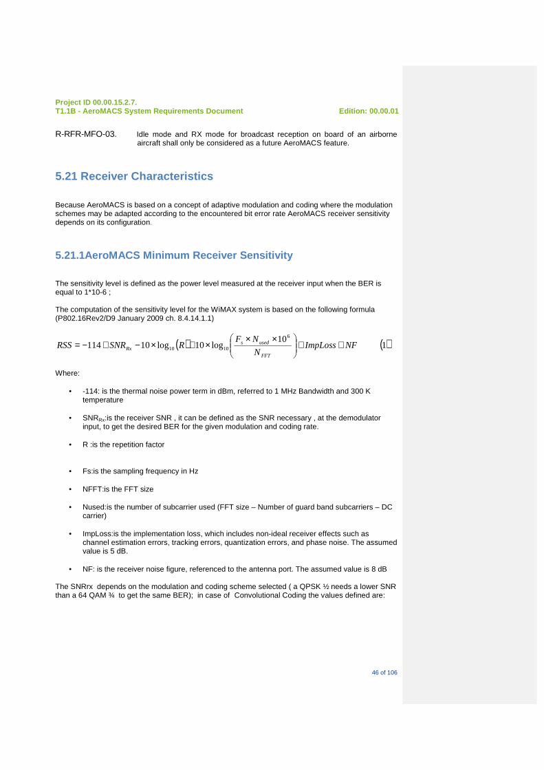
Project ID 00.00.15.2.7. T1.1B - AeroMACS System Requirements Document Edi tion: 00.00.01
46 of 106
R-RFR-MFO-03. Idle mode and RX mode for broadcast reception on board of an airborne
aircraft shall only be considered as a future AeroMACS feature.
5.21 Receiver Characteristics
Because AeroMACS is based on a concept of adaptive modulation and coding where the modulation schemes may be adapted according to the encountered bit error rate AeroMACS receiver sensitivity depends on its configuration.
5.21.1AeroMACS Minimum Receiver Sensitivity
The sensitivity level is defined as the power level measured at the receiver input when the BER is equal to 1*10-6 ; The computation of the sensitivity level for the WiMAX system is based on the following formula (P802.16Rev2/D9 January 2009 ch. 8.4.14.1.1)
( ) ( )1 10
log10log101146
1010 NFImpLossN
NFRSNRRSS
FFT
usedsRx ++
×××+×−+−=
Where:
• -114: is the thermal noise power term in dBm, referred to 1 MHz Bandwidth and 300 K temperature
• SNRRx:is the receiver SNR , it can be defined as the SNR necessary , at the demodulator
input, to get the desired BER for the given modulation and coding rate.
• R :is the repetition factor
• Fs:is the sampling frequency in Hz • NFFT:is the FFT size
• Nused:is the number of subcarrier used (FFT size – Number of guard band subcarriers – DC
carrier)
• ImpLoss:is the implementation loss, which includes non-ideal receiver effects such as channel estimation errors, tracking errors, quantization errors, and phase noise. The assumed value is 5 dB.
• NF: is the receiver noise figure, referenced to the antenna port. The assumed value is 8 dB
The SNRrx depends on the modulation and coding scheme selected ( a QPSK ½ needs a lower SNR than a 64 QAM ¾ to get the same BER); in case of Convolutional Coding the values defined are:

Project ID 00.00.15.2.7. T1.1B - AeroMACS System Requirements Document Edi tion: 00.00.01
47 of 106
Receiver SNR
Modulation Coding rate Receiver SNR (dB)
QPSK 1/2 5
QPSK 3/4 8
16-QAM 1/2 10.5
16-QAM 3/4 14
64-QAM 1/2 16
64-QAM 2/3 18
64-QAM 3/4 20
Table 8 - Receiver SNR
For a WiMAX 5 MHz system the values for the parameters in the PUSC mode are:
• Fs = 5.6 * 10-6
• Nused = 420
• ImpLoss= 5
• NF = 8
• NFFT= 512
• SNRRX = according to Table 8 Receiver SNR Using the above parameters in the formula (1) we get the sensitivity values listed in Table 9
Modulation scheme Rep. Factor Sensitivity
64 qam 3/4 1 -74,37 dBm
64 qam 2/3 1 -76,37 dBm
16 qam 3/4 1 -80,37 dBm
16 qam 1/2 1 -83,87 dBm
qpsk 3/4 1 -86,37 dBm
qpsk 1/2 1 -89,37 dBm
qpsk 1/2 with repetition 2 2 -92,37 dBm
Table 9 – AeroMACS Receiver Sensitivities : Rss
. R-RFR-REC-01. AeroMACS minimum receiver sensitivity will not be higher than the values
indicated in table 9 in case CC is used.

Project ID 00.00.15.2.7. T1.1B - AeroMACS System Requirements Document Edi tion: 00.00.01
48 of 106
R-RFR-REC-02. AeroMACS minimum receiver sensitivity will be 2 dB lower than indicated in table 9 in case CTC is used.
5.21.2 Maximum AeroMACS Receiver Input Signal
R-RFR-REC-03. Both AeroMACS downlink and uplink receivers shall keep full performance functioning with a maximum signal input level of – 30 dBm.
5.21.3 AeroMACS Receiver Maximum Tolerable Input Si gnal
R-RFR-REC-04. The AeroMACS downlink and uplink receivers shall tolerate a maximum input signal of 0 dBm without being destroyed.
5.21.4 AeroMACS Minimum Dynamic Range
The minimum dynamic range is defined as the ratio of the maximum input signal level tolerated and the minimum signal level the system can process. R-RFR-REC-05. BS receiver minimum dynamic range shall be from -30 dBm down to Rss
R-RFR-REC-06. MS receiver minimum dynamic range shall be from - 30dBm down to Rss
5.21.5 Receiver Spurious Emissions
R-RFR-REC-06. Unwanted emission by the receiver in the spurious domain shall comply to CEPT/ERC/REC/74-01.
R-RFR-REC-07. The power of any spurious emissions shall not exceed the values as provided by the table below :
FREQUENCY BAND MEASUREMENT BANDWIDTH MAXIMUM LEVEL
30MHz < f < 1 GHz 100 kHz -57 dBm
1GHz < f < 12,75 GHz 1 MHz -47 dBm
Table 10 - General Receiver Spurious Emission Requi rements

Project ID 00.00.15.2.7. T1.1B - AeroMACS System Requirements Document Edi tion: 00.00.01
49 of 106
5.21.6 Receiver Adjacent Channel Rejection
R-RFR-REC-08. Receiver adjacent channel rejection shall be at least 10 dB when considering 16 QAM ¾ .
R-RFR-REC-09. Receiver adjacent channel rejection shall be at least 4dB when considering 64 QAM ¾ .
5.21.7 Receiver Non Adjacent Channel Rejection
R-RFR-REC-10. Receiver non adjacent channel rejection shall be at least 29 dB when considering 16 QAM ¾ .
R-RFR-REC-11. Receiver non adjacent channel rejection shall be at least 23 dB when considering 64 QAM ¾ .
5.21.8 Receiver Blocking Characteristics
Receiver blocking test conditions will be established in co-operation with ETSI during AeroMACS ETSI standardisation procedures. Receiver blocking specification values will be established in co-operation with ETSI during AeroMACS ETSI standardisation procedures.
5.21.9 Receiver Intermodulation Characteristics
AeroMACS intermodulation characteristics will be established in co-operation with ETSI during AeroMACS ETSI standardisation procedures.
5.21.10 Input System IP3 Requirements
AeroMACS input intermodulation requirements will be established in co-operation with ETSI during AeroMACS ETSI standardisation procedures.
5.22 AeroMACS Transmit Power Control
R-RFR-ATP-01. Transmit power control shall be applied to the AeroMACS uplink.

Project ID 00.00.15.2.7. T1.1B - AeroMACS System Requirements Document Edi tion: 00.00.01
50 of 106
5.22.1 Open Loop Power Control
R-RFR-ATP-02. AeroMACS shall support open loop power control at connection initiation phase.
R-RFR-ATP-03. AeroMACS shall support passive mode open loop as specified under ref 3 para 8.4.10.3.2.
5.22.2 Closed Loop Power Control
R-RFR-ATP-04. AeroMACS shall support closed loop power control under all other operating conditions.
R-RFR-ATP-05. Closed loop power control shall be done in 0,5 dB stepsizes.
R-RFR-ATP-06. Closed loop power control shall start from emission levels of -64 dBm.
Note : the algorithm used for closed loop power control is not standardised and is hence manufacturer specific.
5.22.3 TPC Performance
R-RFR-ATP-07. AeroMACS Transmit Power Control Algorithm shall be designed in such a way that it can handle power attenuations due to pathloss or power fluctuations at rates of at least 30dB/s.

Project ID 00.00.15.2.7. T1.1B - AeroMACS System Requirements Document Edi tion: 00.00.01
51 of 106
6 AeroMACS Functional Requirements
6.1 Operating Altitude
It should be noted that COCR V2.0 has foreseen additional operation of airp ort communications up to 5000 feet – corresponding to a range of around 30 km around the airport (when taking into account a 3 degrees landings scope). Such operating conditions would be very favourable in core area Europe as it will reduce heavily the amount of future L band radios needed seen given the very close proximity of large airports ( 50 km average). However during ITU-R WRC07, AeroMACS - operating in the extended MLS band - has been granted transmission rights for airport surface operations only. R-AFR-OPA-01. Hence within the frame of SESAR P15.2.7 AeroMACS shall assume an
operating altitude of FL 0 (ground) also because only MS speeds of up to 50 knots are considered.
In the future AeroMACS operation in RX mode for Airborne A/C, operating AeroMACS in idle mode, may be considered whenever MS are able to handle speeds of up to 200 knots.
6.2 Primary Services
R-AFR-PRI-01. Packet switched ATC and AOC data shall be the primary service delivered by AeroMACS.
R-AFR-PRI-02. Circuit switched data shall not be supported by AeroMACS.
6.3 Possible Secondary Services
Voice over IP (VOIP) may be considered as a possible secondary service for the future as it is already considered today in the US. Other possible secondary services such as video streaming are to be determined in the future.
6.4 Safety of Life and Regularity of Flight Support
R-AFR-SOL-01. The AeroMACS radio shall be designed to support safety of life and regularity of flight applications for aviation.
R-AFR-SOL-02. All ATC services shall be considered as safety of life applications.

Project ID 00.00.15.2.7. T1.1B - AeroMACS System Requirements Document Edi tion: 00.00.01
52 of 106
R-AFR-SOL-03. AeroMACS shall only support those AOC messages which are considered as a regularity of flight application.
6.5 AeroMACS Availability Figures
R-AFR-AAF-01. AeroMACS shall target an availability figure for service provision of .9995 (see Table 5.8 Ref 1).
R-AFR-AAF-02. AeroMACS shall target an availability figure for service use of .999 (see Table 5.8 Ref 1).
6.6 AeroMACS Continuity Figures
AeroMACS targets a continuity figure for service use of .999 (see Table 5.8 Ref 1).
6.7 AeroMACS Integrity Figures
R-AFR-AIF-01. AeroMACS target integrity figure for service use shall be 10-5 (see Table 5.8 Ref 1).
6.8 Degradation of Safety
The AeroMACS radio is expected to have - as a minimum - an identical safety level as existing VDL mode 2 data link radios – running today’s safety of life ATC as well as AOC data applications (not-tactical). R-AFR-DEG-01. AeroMACS system shall comply to safety requirements as to be derived by
P15.2.7: WA 8.
R-AFR-DEG-02. However, the safety conditions under normal operations (full availability of AeroMACS) shall operate with largely improved safety levels compared to existing safely levels aviation data link radios are operating today.
Project ID 00.00.15.2.7. T1.1B - AeroMACS System Requirements Document Edi tion: 00.00.01
53 of 106
6.9 ATN/IPS : IP Support – ICAO Doc 9896
R-AFR-ATN-01. Because AeroMACS radio definition is based on the IEEE 802.16-2009 standard, AeroMACS shall be based on an all IP radio and ground Internet Protocol (IP) compliant infrastructure as defined in ICAO DOC 9896 (ATN/IPS).
No support for ATN/OSI according to ICAO DOC 9880 is expected initially. Note : ATN IPS/OSI interoperability issues may be resolved by using a gateway. In addition WiMAX Forum 802.16 -2009 specifications support only IPV4 and IPV6 today.
6.10 General provision of Priority and QoS handling Provision of Priority and QoS handling will be treated in P15.2.7 WA2 - 3 and P 15.2.4 and will be composed of a combination of QoS classes – Service flows and scheduler implementation, as well as IP service type mapping.
6.11 Quality of Service
R-AFR-QOS-01. QoS in 802.16 AeroMACS shall be supported by allocating each connection between the MS and the BS (called a service flow in 802.16 terminology) to a specific QoS class. In 802.16e, there are 5 QoS classes.
Note : Strong support for Quality of Service (QoS) can be provided by AeroMACS because it is a connection oriented technology. The mobile station (MS) cannot transmit data until it has been allocated a channel by the Base Station (BS). In the following paragraphs a description is provided of possible AeroMACS supported QoS classes followed by an application example of each class. R-AFR-QOS-02. AeroMACS BSs and MSs shall support the same mandatory Dynamic service
flow procedures required for compliance to WiMAX equipments.
In a successive phase this requirement could be reviewed when the services scenario will be clarified.
6.11.1 Extended Real-Time Polling Service
Extended Real Time Polling Service (ertPS) is defined as a rReal-time service flows that generates variable-sized data packets on a periodic basis.

Project ID 00.00.15.2.7. T1.1B - AeroMACS System Requirements Document Edi tion: 00.00.01
54 of 106
An example of a eRTP based commercial communications application would be VOIP with silence suppression. R-AFR-QOS-03. AeroMACS shall support ertPS
6.11.2 Real-Time Polling Service
Real time Polling Service (rtPS ) is defined as rReal-time data streams comprising variable-sized data packets that are issued at periodic intervals. An example of a rtPS based commercial communications application would be MPEG Video. R-AFR-QOS-04. AeroMACS shall support rtPS
6.11.3 Non-real Time Polling Service
Non Real Time Polling Service (nrtPS) is defined as delay-tolerant data streams comprising variable-sized data packets for which a minimum data rate is required. An example of a nrtPS based commercial communications application would be FTP with guaranteed minimum throughput. R-AFR-QOS-05. AeroMACS shall support nrtPS
6.11.4 Best Effort Service
Best Effort Service (BE) is defined as data streams for which no minimum service level is required and therefore may be handled on a space-available basis. An example of a BE based commercial communications application would be HTTP. R-AFR-QOS-06. AeroMACS shall support BE
6.11.5 Unsolicited Grant Service
Unsolicited grant Service (UGS) is defined as real-time data streams comprising fixed-size data packets issued at periodic intervals – all being delay and delay variance critical. An example of a UGS based commercial communications application would be E1/T1 transport, or circuit switched voice or VOIP without silence suppression. Note : it is expected that in the future there will be no need any longer for circuit switched communications. R-AFR-QOS-07. AeroMACS shall support UGS.

Project ID 00.00.15.2.7. T1.1B - AeroMACS System Requirements Document Edi tion: 00.00.01
55 of 106
6.12 QoS Control
R-AFR-QOS-09. The AeroMACS system profile shall include all features and parameters needed for traffic flow level QoS differentiation.
R-AFR-QOS-10. Such differentiation shall apply to different applications and packet flows from the same IP address.
R-AFR-QOS-11. The AeroMACS profiles shall include all features and parameters needed for user-level QoS and priority differentiation.
6.13 Multicast and Broadcast Support
R-AFR-MBS-01. All BSs and MSs shall support Multicast signalling and bearer connections.
R-AFR-MBS-02. All BSs and MSs shall support Broadcast signalling and bearer connections.
6.14 Radio Resource Management
R-AFR-RRM-01. AeroMACS shall enable advanced RRM for efficient utilization of radio resources. This may be achieved by appropriate measurement/reporting, interference management and flexible resource allocation mechanisms.
6.14.1 Reporting
R-AFR-RRM-02. AeroMACS shall enable advanced RRM by enabling the collection of reliable statistics over different timescales, including system (e.g., dropped call statistics, BS loading conditions, channel occupancy, RSSI ), user (e.g., terminal capabilities, mobility statistics ), flow, packet, etc.
R-AFR-RRM-03. AeroMACS MSs shall support the same measurements required for compliance to the WiMAX MS.
In a successive phase this requirement could be reviewed when the services scenario will be clarified.
6.14.2 Interference Management
R-AFR-RRM-04. AeroMACS shall not support active interference mitigation schemes (DFS)
6.14.3 Resource Allocation Algorithm
As OFDMA allows several users to communicate simultaneously during the same symbol period there is a need to develop an algorithm for user scheduling determination, how to allocate the subcarriers over the users, and how to determine the correct power level setting for each user per burst.

Project ID 00.00.15.2.7. T1.1B - AeroMACS System Requirements Document Edi tion: 00.00.01
56 of 106
Resource allocation in communications is often formulated as a constrained optimalisation method problem where either:
• The total transmit power is minimised with a constraint on the user data rate, or
• The total data rate is maximised with a constraint on total transmit power.
The first option is typically a case for fixed data rate applications while the second bullet option is mostly encountered in bursty packet data environments. So, AeroMACS should make use of a rate-adaptive resource allocation algorithm , i.e., the second option. Different rate adaptive algorithms exist – all having their respective advantages/disadvantages. Algorithms investigated were :
• Maximum Sum Rate ( max throughput)
• Maximum Fairness (equal data rates amongst all users)
• Proportional Rate Constraints (preset proportional rates amongst all users)
• Proportional Fairness Scheduling.
Because the first 3 algorithms mentioned above all try to instantaneously achieve their respective objectives, whereas the last one tries to achieve the objectives over time (e.g., an additional trade off of latency is included) and because COCR has concluded that latency requirements were not that stringent for the most critical safety of life functions the Proportional Fairness Scheduling is probably the best option for AeroMACS. These algorithms are examples of possible implementations. R-AFR-RRM-05. The implementation of AeroMACS resource allocation algorithm shall be
manufacturer dependant.
6.15 Security
This section first presents operational information security requirements applicable to the AeroMACS system. These requirements are mainly based on the results of the preliminary risk analysis performed for the COCRv2 document (for Air Traffic Services and for COCR AOC services).
The additional AOC services identified in SANDRA project and the SJU AOC need study are also considered to derive the following Security requirements. The reader may refer to the Annex of the present document and to the deliverables of the SANDRA project and the SJU AOC need study to get more detailed information.
The commercial WiMAX security features are then checked against these requirements in order to perform a first selection of the security features to be implemented in the AeroMACS and to identify potential shortcomings.
As security does not remain limited to the OSI layers 1 and 2 and extends also to the network, transport and application layers, the WiMAX security shortcomings can be mitigated at upper layers if needed. Moreover, for institutional, commercial or technical reasons, some security features can be implemented at upper layers which may potentially relax the security requirements at AeroMACS level. It is thus necessary to perform a global security assessment encompassing the End-to-End communication infrastructure to derive the exact set of security features to be implemented at AeroMACS system level.
The information regarding the end-to-end communication infrastructure and the related security infrastructure are expected from other SESAR projects (e.g. P15.2.4, P15.2.10). Based on these inputs, the present security requirements will be refined in the frame of the Working Activity 08 of P15.2.7 in order to review the AeroMACS Profile.

Project ID 00.00.15.2.7. T1.1B - AeroMACS System Requirements Document Edi tion: 00.00.01
57 of 106
6.15.1 Security requirements
The AeroMACS system shall ensure the appropriate level of security for the business needs of the target user and for the services provided to this target user. To achieve this goal the AeroMACS system shall meet the following specifications.
R-AFR-SEC-1. The AeroMACS system shall be configurable to support different levels of security for the different users and the different services.
R-AFR-SEC-2. The AeroMACS system shall ensure the appropriate level of security while interconnecting different environments (Aircraft, Surface Vehicles, Air Traffic Service Centre, Airlines Operation Centre and Airport Operations Centre) for different purposes (ATS, AOC-AAC, Airport surface operation).
R-AFR-SEC-3. The AeroMACS system shall ensure the appropriate level of security to support Point-to-Point data Air Traffic services .
R-AFR-SEC-4. The AeroMACS system shall ensure the appropriate level of security to support Ground-to-Air Multicast data Air Traffic services .
R-AFR-SEC-5. The AeroMACS system shall ensure the appropriate level of security to support Ground-to-Air Broadcast data Air Traffic services .
R-AFR-SEC-6. The AeroMACS system shall ensure the appropriate level of security to support Point-to-Point data Aeronautical Operation Control services .
R-AFR-SEC-7. The AeroMACS system shall ensure the appropriate level of security to support Ground-to-Air Multicast data Aeronautical Operation Control services.
R-AFR-SEC-8. The AeroMACS system shall ensure the appropriate level of security to support Point-to-Point surface vehicle operation related da ta services .
R-AFR-SEC-9. The AeroMACS system shall ensure the appropriate level of security to support Multicast AOC-to-surface vehicle data services .
6.15.2Operational information security requirements
The risk analysis performed for COCRv2 has identified the following threats at FCI level (see table 4-9 in COCRv2).

Project ID 00.00.15.2.7. T1.1B - AeroMACS System Requirements Document Edi tion: 00.00.01
58 of 106
Threat Identifier Threat Description
T.DENIAL System resources may become exhausted due to system error, non-malicious user actions, or denial-of-service (DoS) attack.
T.DENIAL.FLOOD An attacker floods a communications segment of the FCI with injected messages in order to reduce the availability of the FCI.
T.DENIAL.INJECT An attacker injects malformed messages into a communications segment of the FCI in order to reduce the availability of the FCI.
T.DENIAL.INTERFERE An attacker injects deliberate RF interference into an RF communication segment of the FCI in order to reduce the availability of the FCI.
T.ENTRY An individual other than an authorised user may gain access via technical or non-technical attack for malicious purposes.
T.ENTRY.ALTER An attacker delays/deletes/injects/modifies/re-directs/re-orders/replays or otherwise alters messages on a communications segment of the FCI in order to reduce the integrity of the FCI.
T.ENTRY.
EAVESDROP
An attacker eavesdrops on messages on a communications segment of the FCI in order to reduce the confidentiality of the FCI.
T.ENTRY.
IMPERSONATE
An attacker impersonates a user of the FCI in order to reduce the confidentiality or integrity of the FCI, or simply to gain free use of the FCI.
Depending on the Data link service, the threat likelihood and threat severity have also been determined to derive Information Security requirements.
In COCRv2 document, Information Security requirements are allocated to the whole End-to-End communication infrastructure (FCI domain) and/or to the FRS (Future Radio System) domain. The scope of Project 15.2.7 is comparable to the FRS domain identified by COCRv2. Consequently all the “COCRv2” Security requirements applicable to the FRS domain will be relevant for the AeroMACS system.
Nevertheless, AeroMACS could also contribute to the mitigation of threats identified at FCI level.
Consequently the COCRv2 Security requirements applicable to the FCI are also considered as a “MAY” requirement rather than a “SHALL” one.
This subsection identifies the Security requirements applicable to the AeroMACS system.
6.15.2.1General requirements
R-AFR-SEC-10. The AeroMACS system shall provide some measure of resistance against deliberate insertion of RF interference (Impact on Availability) (R.FRS-SEC.1a).
Note: In case the deliberate interferer has narrowband characteristics AeroMACS could provide some protection by implementing PUSC. However AeroMACS cannot provide any resistance against wideband deliberate interference.
Such measure can simply be the capability for the AeroMACS system to report to the users in real-time abnormal occupation of the channel in order to enable them to implement appropriate mitigation procedures.
NOTE: In the frame of P15.2.7, it was investigated the need for implementing DFS (Dynamic Frequency Selection) function as a mean of mitigating the risk of intentional jamming. But it was

Project ID 00.00.15.2.7. T1.1B - AeroMACS System Requirements Document Edi tion: 00.00.01
59 of 106
concluded that it would add much complexity on the AeroMACS system and especially on the frequency planning with not really proven results.
R-AFR-SEC-11. The AeroMACS system should support some reliability and robustness means to mitigate denial of service attacks (Impact on Availability) (based on R.FCI-SEC.1a).
Note: This requirement needs further investigation in SESAR P15.2.7 WA8.
6.15.2.2Point-to-Point services
COCRv2 ATS: ACL, ACM, COTRAC (Interactive), COTRAC (Wilco), D-ALERT, DCL, D-FLUP, DLL, D-TAXI, FLIPCY, FLIPINT, PPD, URCO (and SURV/Periodic report)
COCRv2 AOC services: AOCDLL, CABINLOG, FLTLOG, FLTPLAN, LOADSHT, NOTAM, OOOI, SWLOAD, TECHLOG, UPLIB, WXGRAPH, WXRT, and WXTEXT.
Additional AOC services (SANDRA): EFF, CONF, PERF, REFUEL, DE-ICING, VQAR, CVM, TELEMED, CabMAINTTRT
SJU Study: FOQA for encryption. All other services
Surface operation: DLL, AOPC DLL, ATC, AOPCL, V-PLAN, DV-ALERT, DS-ALERT and SURV.
Based on COCRv2, the related Security requirements applicable to the AeroMACS system are the following:
R-AFR-SEC-12. The AeroMACS system may support message authentication and integrity to prevent message alteration attacks (Impact on Integrity) (based on R.FRS-SEC.2a and R.FCI-SEC.2a).
R-AFR-SEC-13. The AeroMACS system may support entity authentication to mitigate impersonation attacks (Impact on Integrity) (based on R-FRS-SEC.3a and R.FCI.SEC.4a).
R-AFR-SEC-14. For specific services (e.g. D-ALERT, LOADSHT) the AeroMACS system may support encryption to mitigate eavesdropping (Impact on Confidentiality) (based on R.FCI.SEC.3b).
6.15.2.3Ground-to-Air Multicast services
COCRv2 ATS: AMC, D-ATIS, D-OTIS, D-RVR, D-SIG, D-SIGMET (and TIS-B).
COCRv2 AOC services: no service identified.
Additional AOC services (SANDRA): no service identified
Surface operation: D-OTIS
Based on COCRv2, the related Security requirements applicable to the AeroMACS system are the following:
R-AFR-SEC-15. The AeroMACS system may support message authentication and integrity to prevent message alteration attacks (Impact on Integrity) (based on R.FRS-SEC.2a and R.FCI-SEC.2a).
R-AFR-SEC-16. The AeroMACS system may support entity authentication to mitigate

Project ID 00.00.15.2.7. T1.1B - AeroMACS System Requirements Document Edi tion: 00.00.01
60 of 106
impersonation attacks (Impact on Integrity) (based on R-FRS-SEC.3a and R.FCI.SEC.4a).
6.15.2.4Ground-to-Air Broadcast services
COCRv2 ATS: AMC, D-ATIS, D-OTIS, D-RVR, D-SIG, D-SIGMET (and TIS-B).
COCRv2 AOC services: no service identified
Additional AOC services (SANDRA): no service identified
Surface operation: TIS-B, D-OTIS
Based on COCRv2, the related Security requirements applicable to the AeroMACS system are the following:
R-AFR-SEC-17. The AeroMACS system may support message authentication and integrity to prevent message alteration attacks (Impact on Integrity) (based on R.FRS-SEC.2a and R.FCI-SEC.2a).
R-AFR-SEC-18. The AeroMACS system may support entity authentication to mitigate impersonation attacks (Impact on Integrity) (based on R-FRS-SEC.3a and R.FCI.SEC.4a).
6.15.3 AeroMACS Security System
In order to protect AeroMACS against all security threats mentioned in paragraph 6.15.2. and to be compliant with Operational Information Security requirements the following measures shall be taken:
6.15.3.1 Key management
R-AFR-SEC-19. Privacy Key Management (PKM) protocol version 2 shall be activated. Indeed, PKMv2 proposes mutual authentication between BS and MS whereas PKMv1 allows only unidirectional authentication.
R-AFR-SEC-20. The use of Security Association (SA) to maintain state of security for communications shall be taken into account.
R-AFR-SEC-21. Key management and refresh algorithms shall be activated to manage correctly key distribution issues.
6.15.3.2 Multicast/broadcast services
In order to protect operational Multicast and Broadcast services (e.g. D-ATIS), Multicast and Broadcast Rekeying Algorithm (MBRA) could be selected for management traffic required to set up such type of operation. This algorithm will provide robustness for key exchange mechanisms used with authentication, integrity and confidentiality security algorithms between MS and BS.
Moreover, in order to avoid specific rogue (spoofing/impersonate) attacks, Rekeying Capabilities (i.e. MBRA mechanism) could be enabled specifically on the MS side.

Project ID 00.00.15.2.7. T1.1B - AeroMACS System Requirements Document Edi tion: 00.00.01
61 of 106
For specific Management messages, authentication is not provided by the WiMAX security framework. Besides encryption mechanism for all Management messages is not currently addressed by the WiMAX Forum. Nevertheless such security features could be implemented in the AeroMACS system in order to provide enhanced Integrity and Authentication of Operational transaction.
To be further investigated in SESAR P15.2.7 WA8.
6.15.3.3Authentication: Extensible Authentication P rotocol
R-AFR-SEC-22. AeroMACS shall be compatible with advanced authorization policies through AAA-based implementation (AAA: Authorization, Authentication and Accounting server), in order to prevent from unauthorized network entry.
R-AFR-SEC-23. In order to ensure that a given user or device is “as stated” AeroMACS shall implement an authentication procedure.
NOTE: at this stage, it is proposed to stick to the WiMAX forum profiles and thus we do not consider device authentication. Nevertheless the need for user and device authentication will be investigated in SESAR P15.2.7 WA8 as well as the methodology to implement device authentication.
R-AFR-SEC-24. AeroMACS user authentication procedures shall be based on Extensible Authentication Protocol (EAP – IETF RFC 3748) running over private key management version PKM v2.2.
Note: AeroMACS device authentication procedures could be justified and based on RSA.
NOTE: RSA is not currently supported by the WiMAX Forum, only EAP is supported. However RSA is more robust and could be preferred to EAP depending on the results of the Security analysis which will be conducted in the frame of WA08. NOTE: An AeroMACS BS will relay the authentication protocol to the authenticator over the access service network (ASN). From the authenticator to the authentication server, EAP can be carried either over Remote Access Dial-in User Service (RADIUS) or over DIAMETER NOTE: DIAMETER being the preferred UDP application as it has greater reliability, security and roaming support than RADIUS – but is not being backward compatible with RADIUS). R-AFR-SEC-25. Authentication support shall form part of the AAA (Authorisation,
Authentication and Accounting) implementation.
6.15.3.4 Authorisation Policy Support
R-AFR-SEC-26. Authorisation policy shall be supported within AeroMACS at both BS and MS sides.
R-AFR-SEC-27. Authorisation support shall form part of the AAA (Authorisation, Authentication and Accounting) implementation.
6.15.3.5 Accounting

Project ID 00.00.15.2.7. T1.1B - AeroMACS System Requirements Document Edi tion: 00.00.01
62 of 106
Though strictly speaking not a pure security measure, accounting will guarantee the correct billing of data traffic to the respective users. Whether or not AeroMACS will implement accounting will largely depend on the way airport infrastructure will be handled by airport operators. R-AFR-SEC-28. Under SESAR P15.2.7 AeroMACS shall not support accounting.
6.15.3.6 Link Layer Data Encryption
R-AFR-SEC-29. AeroMACS shall support the Advanced Encryption Standard (AES) operating in countermode with Cipher-Block Chaining Message Authentication (CBC-MAC defined per RFC 3610) for link layer data encryption.
R-AFR-SEC-30. AeroMACS shall use MAC level signalling data encryption, in particular, it shall support Encryption mechanisms such as AES – CCM because it is the most robust one.
6.15.4 WiMAX security feature shortcomings and pote ntial evolution
In this section, we introduce just a few examples a WiMAX security feature shortcomings. To correctly assess the need to mitigate such vulnerabilities and identify the potential technical solution, a global risk analysis shall be performed. Conclusions of this analysis will provide a list of all WiMAX resilient vulnerabilities, mitigations we can deploy for each of them and the related security risk level induced. Such analysis is performed in the frame of P15.2.7 WA08 on the basis of the outcomes issued by the P15.2.10 and P15.2.4. The pertinence of implementing the following security features will have to be proven in performing a Risk Analysis on the End-to-End Air-Ground communication infrastructure:
• AeroMACS could deploy different symmetric key sharing mechanisms (GTEK: Group Traffic Encryption Key) for multicast and broadcast services between one Base Station and different Mobile Station clusters to avoid BS rogue attack.
• AeroMACS couldl deploy encryption and authentication mechanisms for MAC level signalling data related to Multi/Broadcast operation in order to increase robustness of signalling traffic. For instance, AeroMACS shall use MOB_TRF-IND message authentication (e.g. HMAC) to avoid excessive power consumption in sleep mode for MS in order to avoid DoS attack.
6.16 Handover
R-AFR-HAN-01. Under P15.2.7 / P9.16 AeroMACS BSs and MSs shall support the hard handover procedures as required in the AeroMACS profiles.
R-AFR-HAN-02. AeroMACS shall support handover between all cell sectorisation types.
Note: AeroMACS will only support hard handover between AeroMACS systems operating with the same bandwidth in case there would be a need to implement 10 MHz AeroMACS systems. Hence each individual airport will support only one AeroMACS bandwidth.

Project ID 00.00.15.2.7. T1.1B - AeroMACS System Requirements Document Edi tion: 00.00.01
63 of 106
In a successive phase the hard handover requirement could be reviewed when the services scenario will be clarified. R-AFR-HAN-03. BS initiated handover shall be used in case load balancing at LLC level is
supported.
6.17 Support for Multi-Hop Relay
R-AFR-SMR-01. Under SESAR P15.2.7 the multi-hop relay as defined within IEEE 802.16j-2009 shall not be supported
Note : IEEE 802.16j-2009 is not covered by P15.2.7 PIR.
6.18 Co-Deployment with other Networks
R-AFR-CDN-01. AeroMACS shall support, at the airport, the extension of SWIM to the aircraft.
R-AFR-CDN-02. AeroMACS ASN shall also attach to PENS (SESAR P15.2.10) or to a local LAN / WAN infrastructure which is already part of the airport.
6.18.1 Co-Existence Scenarios
R-AFR-PER-01. AeroMACS shall co-exist with other wireless LAN’s being operated at the airport such as WIFI® (in operation at most major European airports since 2000).
The co-existence scenario will mainly handle the wired ground infrastructure issues and not the RF parts as WIFI operates at 2,4 GHz. Therefore no major interference issues are to be expected between WIFI and AeroMACS
6.19 Performance Requirements
Performance requirements – in particular- for data throughputs - are difficult to determine for AeroMACS as too many parameters play an important role in the throughput determination. However some estimates have been obtained on mobile WIMAX from “live” systems as provided by Reference 7. In order to have a reference when analysing performance we define a generic WiMAX equipment composed of :
• One BS with its antenna • One MS with its antenna

Project ID 00.00.15.2.7. T1.1B - AeroMACS System Requirements Document Edi tion: 00.00.01
64 of 106
This elementary equipment provides an initial covering. According to the airport’s geometry, the BS and antenna arrangement will be evaluated in order to find a trade-off between the targeted capacity (services, traffic) and the interference limitations (regulation authorities).
R-AFR-PER-01. Radio planning tools shall be used to adjust the integration of AeroMACS at the airport surface (frequency re-use, localization of BS, etc …).
OMNI SECTORIAL
BSBS
BSBS
A
B
A
B
C
f1
f2
f3
f1
f2
f33 BS
Figure 4 Example of possible antenna configurations to fit different airport areas.
6.19.1AeroMACS Throughput Estimation (PHY Throughpu t)
Overall theoretical AeroMACS throughput or AeroMACS PHY throughput is defined as the peak raw bit rate measured in bits/sec at which bits are delivered by the PHY layer to the MAC layer. A compilation of these parameters are listed hereafter with all MAJOR factors – limited to those which can be impacted by the AeroMACS profiles or SRD - indicated in BOLD.
6.19.1.1 RF Parameters
1. BW: the larger the BW the larger the data throughput. BW considered shall be 5 MHz.
2. EIRP TX EIRP: Output power at antenna shall be made large enough to overcome expected pathloss - while taking into account compliance to Ref 15.
3. RX NF: The RX Noise figure is the major player allowing an overall reduction to Globalstar interference.
4. Path Loss: The MS physical position with respect to the BS it is attached to. The closer the MS is located the higher the data throughputs which can be provided.
4.5. Path Loss : The location of BS at the airport should be such that as many MS as possible can be connected under LOS conditions
5.6. Antenna gain , MIMO/AAS
6.7. Modulation Schemes : the higher the modulation scheme the larger the data throughput.
7.8. Sectorisation : The more sectors deployed for the same coverage area and equal amount of users the higher the data throughput can be made per user.
Formatted: Bullets and Numbering

Project ID 00.00.15.2.7. T1.1B - AeroMACS System Requirements Document Edi tion: 00.00.01
65 of 106
6.19.1.2 PHY Mode of Operation Parameters
1. DL/UL: This ratio impacts throughput for any particular downlink or uplink.
2. FEC mode of operation: Different FEC rates are being provided having rates starting from ½; 2/3; ¾; 5/6 – made available for CC and CTC FECs. In addition to this, various repetition rate factors are available : 1, 2, 4, 6.
3. CP value: a fixed CP value of 1/8 is foreseen by WMF profiles.
4. TTG, RTG : The shorter TTG and RTG values are, the higher the throughput. Nevertheless values should be such that propagation losses do not cause any DL/UL ISI collisions. For AeroMACS the value as foreseen by the WMF is taken.
6.19.2 Theoretical Sector Throughput
The following table provides an overview of the theoretical peak raw data throughputs which AeroMACS could provide.

Project ID 00.00.15.2.7. T1.1B - AeroMACS System Requirements Document Edi tion: 00.00.01
66 of 106
12WiMAXprofile
DataSymbol
Split
DownLinkSymbols
UpLink
Sym(35:12) (28:9) 28 9
(32:15) (25:12) 25 12
(29:18) (22:15) 22 15(26:21) (19:18) 19 18
Mod&
codingrate
Datacarr
SymbolPeriod
[us]
bitsper
symbol
Codingrate
Datasymbols
usedper frame
OFDMsymbolsper frame
AchievableData rate
[Mb/s]
Mod&
codingrate
Datacarr
SymbolPeriod
[us]
bitsper
symbol
Codingrate
Data symbols
usedper frame
OFDMsymbolsper frame
AchievableData rate
[Mb/s]
64QAM 5/6 720 102.9 6 5/6 25 48 18.2 Downlink 64QAM 5/6 560 102.9 6 5/6 12 48 6.8 Uplink64QAM 3/4 720 102.9 6 3/4 25 48 16.4 Downlink 64QAM 3/4 560 102.9 6 3/4 12 48 6.1 Uplink64QAM 2/3 720 102.9 6 2/3 25 48 14.6 Downlink 64QAM 2/3 560 102.9 6 2/3 12 48 5.4 Uplink64QAM 1/2 720 102.9 6 1/2 25 48 10.9 Downlink 64QAM 1/2 560 102.9 6 1/2 12 48 4.1 Uplink16QAM 3/4 720 102.9 4 3/4 25 48 10.9 Downlink 16QAM 3/4 560 102.9 4 3/4 12 48 4.1 Uplink16QAM 1/2 720 102.9 4 1/2 25 48 7.3 Downlink 16QAM 1/2 560 102.9 4 1/2 12 48 2.7 UplinkQPSK 3/4 720 102.9 2 3/4 25 48 5.5 Downlink QPSK 3/4 560 102.9 2 3/4 12 48 2.0 UplinkQPSK 1/2 720 102.9 2 1/2 25 48 3.6 Downlink QPSK 1/2 560 102.9 2 1/2 12 48 1.4 Uplink
Mod&
codingrate
Datacarrie
rs
SymbolPeriod
[us]
bitsper
symbol
Codingrate
Datasymbols
usedper frame
OFDMsymbolsper frame
AchievableData rate
[Mb/s]
Mod&
codingrate
Datacarriers
SymbolPeriod
[us]
bitsper
symbol
Codingrate
Data symbols
usedper frame
OFDMsymbolsper frame
AchievableData rate
[Mb/s]
64QAM 5/6 360 102.9 6 5/6 25 48 9.1 Downlink 64QAM 5/6 272 102.9 6 5/6 12 48 3.3 Uplink64QAM 3/4 360 102.9 6 3/4 25 48 8.2 Downlink 64QAM 3/4 272 102.9 6 3/4 12 48 3.0 Uplink64QAM 2/3 360 102.9 6 2/3 25 48 7.3 Downlink 64QAM 2/3 272 102.9 6 2/3 12 48 2.6 Uplink64QAM 1/2 360 102.9 6 1/2 25 48 5.5 Downlink 64QAM 1/2 272 102.9 6 1/2 12 48 2.0 Uplink16QAM 3/4 360 102.9 4 3/4 25 48 5.5 Downlink 16QAM 3/4 272 102.9 4 3/4 12 48 2.0 Uplink16QAM 1/2 360 102.9 4 1/2 25 48 3.6 Downlink 16QAM 1/2 272 102.9 4 1/2 12 48 1.3 UplinkQPSK 3/4 360 102.9 2 3/4 25 48 2.7 Downlink QPSK 3/4 272 102.9 2 3/4 12 48 1.0 UplinkQPSK 1/2 360 102.9 2 1/2 25 48 1.8 Downlink QPSK 1/2 272 102.9 2 1/2 12 48 0.7 Uplink
Number of OFDM Symbols in UL
Channel bandwidth: 10 MHz
Channel bandwidth: 5 MHz
Table 11Theoretical AeroMACS Downlink and Uplink ra w data throughputs for DL/UL ratio of 2/1

Project ID 00.00.15.2.7. T1.1B - AeroMACS System Requirements Document Edi tion: 00.00.01
67 of 106
6.19.3 DL and UL Theoretical Data Throughput Estima tions per User
It is important for the airports service providers and for the future development of cell planning tools to have an idea of the User data throughput AeroMACS is supposed to provide.
However the reader should note that the overall data throughputs as provided under Ref 1 have modified significantly due to further increase of future AOC applications as referred to in the Annexes 2,3 and 4, so this will obviously also impact the individual user data throughput.
Individual User data throughputs are also highly dependant on the physical position vis-à-vis its BS as well its position on the airport as such (gate, taxiway, ramp, ..etc).
Therefore - for the time being - the theoretical target raw data user throughput requirements will be derived from Table 11 while taking into account the following assumptions:
• DL/UL ratio 2/1
• All users attached to a BS have statistically varying data load requirements such that their aggregated average data load does not exceed the overall peak data rate of the BS.
• Taxiway (+ part of ramp area) assumptions ( macro AeroMACS sector) :
i. 50 A/C attached to the BS simultaneously.
ii. QPSK ¾ for average and QPSK ½ for minimum data throughputs
• Gate docking stations assumptions ( micro AeroMACS sector) :
i. 15 A/C attached to the BS simultaneously
ii. 16 QAM ¾ for average and QPSK ¾ for minimum data throughputs
6.19.3.1 DL Target Average Theoretical User Data ra te Taxiway
R-AFR-PER-02. The DL target average theoretical user data rate on the taxiway shall be 50 kbps.
6.19.3.2UL Target Average Theoretical User Data rat e Taxiway
R-AFR-PER-03. The UL target average theoretical user data rate on the taxiway shall be 20 kbps
6.19.3.3Target DL Mimimum Average Theoretical User Data Rate Taxiway
R-AFR-PER-04. The DL target average minimum theoretical user data rate on the taxiway shall be 30 kbps.

Project ID 00.00.15.2.7. T1.1B - AeroMACS System Requirements Document Edi tion: 00.00.01
68 of 106
6.19.3.4Target UL Mimimum Average Theoretical User Data Rate Taxiway
R-AFR-PER-05. The UL target minimum average theoretical user data rate on the taxiway shall be 14 kbps.
6.19.3.5DL Target Average Theoretical User Data rat e at the Gate
R-AFR-PER-06. The DL target average theoretical user data rate at the gate shall be 350 kbps.
6.19.3.6UL Target Average Theoretical User Data rat e at theGate
R-AFR-PER-07. The UL target average theoretical user data rate at the gate shall be 130 kbps.
6.19.3.7Target DL Mimimum Average Theoretical User Data Rate at the Gate
R-AFR-PER-08. The DL target minimum average theoretical user data rate at the gate shall be 180 kbps.
6.19.3.8Target UL Mimimum Average Theoretical User Data Rate at the Gate
R-AFR-PER-09. The UL target minimum average theoretical user data rate at the gate shall be 60 kbps.
6.19.4 Need to re-visit the User data throughputs
After finalisation of SESAR P15.2.7 WA2: channel and traffic models all the targets mentioned above may need to be revisited.
• Channel model may lead to other capacity requirements where amount of users per sector needs to be revised
• Traffic model may lead to other user data throughput requirements.
6.19.5Need to revisit Globalstar Interference

Project ID 00.00.15.2.7. T1.1B - AeroMACS System Requirements Document Edi tion: 00.00.01
69 of 106
Under P15.2.7 WA1 T1.5 the impact of AeroMACS deployment on Globalstar interference will be estimated. This may have a direct impact on possible BS deployment limitations and hence on overall data throughputs supported by AerMACS.
6.19.6 Latency
The following latency requirements will be met by the system, under unloaded conditions.
6.19.6.1 Data Latency The data latency is defined as the one-way transit time between a packet being available at the IP layer (Tx reference point) in either the MS/ Radio Access Network and the availability of this packet at IP layer (Rx reference point) in the Radio Access Network / MS.
Figure 5 Ilustration of reference points for the ma ximum data latency
( drawing reference WiMAX Forum xxx) R-AFR-PER-10. Downlink one way data latency shall be < 20 ms (TBC in SESAR P15.2.7
WA3).
R-AFR-PER-11. Uplink one way data latency shall be < 40 ms (TBC in SESAR P15.2.7 WA3). .
6.19.6.2 Round Trip Ping Latency
R-AFR-PER-12. The Round Trip Ping Latency, measured at the edge of the radio access network, using standard MS initiated 32 byte IP packets shall be < 60 msec, assuming that the MS is in active mode and that the Connection Identifier (CID) has already been allocated.

Project ID 00.00.15.2.7. T1.1B - AeroMACS System Requirements Document Edi tion: 00.00.01
70 of 106
6.19.6.3 State Transition Latency State transition delay is defined as the transition from IDLE_STATE to ACTIVE_STATE. IDLE_STATE to ACTIVE_STATE transition latency is defined as the time it takes for a device to go from an idle state (fully authenticated/registered and monitoring the control channel) to when it begins exchanging data with the network on a traffic channel measured from the paging indication (i.e., not including the paging period). R-AFR-PER-13. State transitions latency shall be < 50 ms (TBC in SESAR P15.2.7 WA3).
6.19.7 Handover Interruption Time
This section addresses handover interruption time requirements applicable to handovers between AeroMACS BSs for intra- and inter-frequency handover. The handover interruption time is specified as the time duration that a MS cannot receive data from any BS during a handover.
R-AFR-HAN-01. AeroMACS handover interruption time shall be < 200 ms (TBC in SESAR P15.2.7 WA3)..
6.20 AeroMACS scanning Note: Scanning is defined as the process executed by the MS from sensing to detection of the channel carrier frequency i.e. to MAC synchronisation (DL/UL MAP decoding). The extended MLS band spans from 5091- 5150 MHz. As an AeroMACS radio has 5 MHz bandwidth, several AeroMACS will operate on different frequency channels within the extended C band. R-AFR-SCA-01.AeroMACS shall contain an automatic channel detection and selection procedures.
R-AFR-SCA-02.AeroMACS shall be able to scan through the 11 channels as defined within the preferred frequency set within TBD (to be defined under SESAR P15.2.7 WA3) seconds.
R-AFR-SCA-03. AeroMACS shall be able to scan the entire bandwidth using a step size of 250 kHz within TBD (to be defined under SESAR P15.2.7 WA3) seconds.
Note: Today all analogue radio systems are manually tuned by the pilot, AeroMACS is supposed to need no pilot intervention.
6.21 Layer 3 Mobility

Project ID 00.00.15.2.7. T1.1B - AeroMACS System Requirements Document Edi tion: 00.00.01
71 of 106
R-AFR-LAY-01. Under P 15.2.7/ P 9.16 AeroMACS shall not support MIP IPv4.
Note: Layer 3 mobility requirements will be covered under P 15.2.4
6.22 AeroMACS Equipment Cost
R-AFR-AEC-01. The system design shall seek to keep costs for both ground and airborne systems segments to an absolute minimum, compared to present avionics communication system costs.
R-AFR-AEC-02. If possible - the use of commercial off-the-shelf (COTS) products shall be integrated to a maximum extent possible.
6.22.1 Ground Infrastructure
R-AFR-AEC-03. AeroMACS’s required ground segment infrastructure shall bear an acceptable cost and hence - to the maximum extent - be based on COTS products.
However it should be noted that all CNS ground infrastructure to be used for ATM services have to follow the guidelines for the assurance of software contained in non-airborne CNS/ATM systems. R-AFR-AEC-04. AeroMACS BSs, ASN, CSN shall comply to the DO-278 / ED-109
(RTCA/EUROCAE) standard appropriate DAL level.
R-AFR-AEC-05. For Europe all CNS/ATM non avionics ground equipment shall comply to COMMISSION REGULATION (EC) No 482/2008.
6.23 Incremental Capacity Requirements
R-AFR-ICR-01. The ground infrastructure required for AeroMACS shall be implemented based on an incremental capacity / capability basis.
6.24 AeroMACS Legacy Requirements
This section contains general legacy requirements for the AeroMACS system. These requirements are intended to address and supplement where needed the future high level AeroMACS requirements specified following the publication of IEEE 802.16-2009 for Mobile Broadband Wireless Access Systems.

Project ID 00.00.15.2.7. T1.1B - AeroMACS System Requirements Document Edi tion: 00.00.01
72 of 106
6.24.1 Future AeroMACS Developments
Future AeroMACS may evolve in the future but it should all remain backward compatible with the previous agreed and implemented specifications (this should cover the initial existing AeroMACS systems as developed). This is very important given the regular release by WMF of new system profiles. R-AFR-ALR-01. Whether new IEEE 802.16-2009 releases and/ or profiles shall be made part
of AeroMACS standard shall depend on the outcome of a cost/ benefit analyses and conclusion by international regulatory bodies.
R-AFR-ALR-02. Under SESAR P15.2.7 and P9.16 all joint effort between Eurocontrol/EUROCAE and FAA/RTCA shall be concentrated and based on Release 1.5 v xx / 5 MHz TDD.
R-AFR-ALR-02.R-AFR-ALR-03.Please note that AeroMACS shall not support the older IEEE 802.16 (Fixed Broadband Wireless Access) as no backward compatibility was ever foreseen between mobile and fixed WiMAX.
All enhancements included as part of AeroMACS shoul d promote the concept of continued evolution, allowin g AeroMACS to maintain competitive performance as IEE E 802.16-2009 profiles are upgraded and technology advances beyond 802.16-2009 profile Release 1. Nevertheless the number of profiles made available shall be kept to the absolute minimum given the high certification costs expected for the airborne side. Also all new standards under development – envisaging backward compatibility with IEEE 802.16-2009 from i ts beginning - such as IEEE 802.16 m, could eventually be made part of AeroMACS in case of proven positive co st benefit analyses and if internationally agreed on.

Project ID 00.00.15.2.7. T1.1B - AeroMACS System Requirements Document Edi tion: 00.00.01
73 of 106
6.24.2 Transition and Backward Compatibility
R-AFR-ALR-03.R-AFR-ALR-04.Any transition related to the implementation of a new AeroMACS profile which has been released shall always guarantee full backward compatibility. This guarantee should be respected internationally.

Project ID 00.00.15.2.7. T1.1B - AeroMACS System Requirements Document Edi tion: 00.00.01
74 of 106
7 SYNCHRONISATON AND TIMING REQUIREMENTS
7.1 Introduction
One of the major challenges during the development of any digital radio, are management and implementation of all the states a radio has to go through before the actual radio connection is established. In general these states can be categorized by various synchronization steps. It is only after these steps and procedures have been successfully executed that an error free connection over a radio link can be established. Because AeroMACS is OFDMA based, the necessary synchronisation steps involve both frequency as well as time synchronisation between base station and mobile unit. After these synchronisation and timing steps have been carried out successfully all UL frames - from all MS transmitting in the UL and located at all possible distances within the BS coverage area - will arrive at the BS within a pre-determined power range and all time aligned to the UL sub frame.
7.1.1 Synchronisation and Timing First Step
The MS will scan the AeroMACS frequency band by reading the frequency list.
Once the MS detects a BS the MS will synchronize itself to the BS by searching continuously for the frame pre-ambles, symbols which are transmitted continuously in the DL sub frames.
After having synchronised to the preamble the MS will read the transmit parameters found in those data packets containing a FCH and a UCD and DCD description (periodically sent).
7.1.2 Synchronisation and Timing Second Step : Ini tial Ranging
After having read the UCD and DCD the MS will select randomly a CDMA ranging code (1 out of N), which will be BPSK modulated across the UL ranging channel (a group of 6 subchannels - containing 144 frequency sub carriers – its exact location being defined by the BS in the DL-MAP and UL-MAP).
The MS transmits the CDMA code at random times in the UL subframe as long as there is a ranging opportunity (ranging opportunity is available through reading the UL_MAP during the next DL subframe. These functions are handled at MAC layer by the RNG-REQ message using CID=0x0000. If the BS does not reply on this message the RNG-REQ is retransmitted but each time with a higher output power step.
At the receiver side the BS monitors the UL ranging channel. The BS is required to detect all initial ranging codes received from all MS who are willing to register (collisions are allowed). For each initial ranging code received, the BS estimates for each MS its individual timing and frequency offset as well as the output power to be emitted. The BS also broadcast for every individual MS its status notification of either successful or retransmission ranging. These functions are handled at BS MAC layer in the RNG-RSP message.
7.2 IEEE 802.16-2009 Synchronization Hooks

Project ID 00.00.15.2.7. T1.1B - AeroMACS System Requirements Document Edi tion: 00.00.01
75 of 106
While synchronization procedures themselves have not been standardized by IEEE, the IEEE802.16e standard has foreseen specific elements such as :
• pilot carriers • preambles • CDMA ranging codes • midambles • Cyclic Prefix
all allowing the receiver to synchronize. Note : Within IEEE 802.16-2009 no standardisation is foreseen on the way synchronisation algorithm is implemented by an AeroMACS equipment manufacturer. For AeroMACS some specific issues have to be addressed as described in the following sections:
7.3 AeroMACS Synchronization Requirements
1.R-SYN-S&T-01. AeroMACS shall take the necessary precautions that synchronisation procedures are optimised in such a way that no additional or new synchronisation hooks / elements are needed in addition to those already provided within the IEEE 802.16-2009 standard.
2.R-SYN-S&T-02. AerMACS Synchronisation dwell times shall be as short as possible. (<150 ms: value TBC after P15.2.7 WA3 finalisation).
R-SYN-S&T-03. AeroMACS dwell times shall be long enough to ensure that the probability of false synchronisation would be < 0,1 % ( TBC after P15.2.7 WA3 finalisation).
R-SYN-S&T-04. In terms of probability of synchronisation DISTINGUISH the false alarm case i.e. detecting a not existing preamble from the correct pre-amble detection case. Values will be provided after WA3 will be finalised.
3.Note: AeroMACS uplink may use a higher repetition rate of mid-amble transmissions (every 8 symbols in stead of every 32 or 16 symbols) in order to handle more accurate time synchronisation and withstand higher Doppler speeds (yielding larger Doppler shifts).
7.3.1 MS Unit
Only one signal reference source will be used for both transmit and receive functions at the MS unit. This will ease the testing against Doppler effects in the lab. R-SYN-S&T-05. AeroMACS MS shall able to synchronise at the limit of the AeroMACS cell
size.
5.R-SYN-S&T-06. AeroMACS MS shall be able to synchronise while encountering Doppler effects evoked by maximum ground speed of 50 knots.
R-SYN-S&T-07. Both centre frequency and sampling clock shall be retrieved from the same
reference source.
Formatted: Bullets and Numbering
Formatted: Bullets and Numbering
Formatted: Bullets and Numbering

Project ID 00.00.15.2.7. T1.1B - AeroMACS System Requirements Document Edi tion: 00.00.01
76 of 106
R-SYN-S&T-08. Under all operating conditions (Doppler, fading, temperature) the MS uplink transmissions shall be locked to the BS centre frequency, so that the MS centre frequency shall not deviate by more than 2% of the subcarrier spacing.
It is estimated that locking within a 2% range would result into a 0,1 dB loss of SNR ratio for SNR = 10 dB and a loss of 1 dB SNR for SNR ratio of 20 dB. (see ref 24). R-SYN-S&T-09. The MS unit shall not start uplink transmission before this synchronisation
lock has been successfully achieved.
R-SYN-S&T-10. During normal operation the MS unit shall track all changes continuously due to Doppler and X-tal oscillator drifts. If synchronisation is lost the MS shall stop transmitting immediately.
R-SYN-S&T-11. All MS units shall acquire and adjust their timing such that all uplink symbols arrive coincident at the BS within an accuracy of less than 50% of the minimum cyclic prefix (CP). This requirement is not only linked to synchronisation but is also a function of channel conditions.
7.3.2 BS Unit
While not strictly needed it is supposed that also the BS uses a single reference source for both transmit and receiver functions. R-SYN-S&T-12. The AeroMACS BS reference oscillator shall have a frequency tolerance <+/-
1ppm.
This value has been decreased compared to the IEEE 802.16-2009 standard seen given the much higher operating frequency and Doppler shifts encountered in aviation.
7.3.3 Network Synchronization
It is highly recommended that all BSs located at an airport are time synchronized onto one common master timing reference such as GPS or Galileo. R-SYN-S&T-13. The synchronization time reference shall be a 1pps pulse and the frequency
reference shall be a 10 MHz signal.
R-SYN-S&T-14. In case of loss of master time reference the network shall continue its operations but once the master time reference is available again each individual BS time source shall lock again onto the master.
7.3.3.1 Network Synchronization Redundancy
R-SYN-S&T-15. Because AeroMACS carries safety of life data all ground network shall foresee a redundant synchronisation source to increase the overall network availability.

Project ID 00.00.15.2.7. T1.1B - AeroMACS System Requirements Document Edi tion: 00.00.01
77 of 106
Note : Synchronization redundancy could be obtained through standards such as GPS, Galileo, Precision Time Protocol (PTP) as defined by IEEE 1588 - 2008 : “Standard for a Precision Clock Synchronization Protocol for Networked Measurement and Control Systems”. Under P15.2.7 and P9.16 there is no need for a redundant timing reference source. Note : Older standards such as Network Time Protocol (NTP) are considered not precise enough to support the synchronisation requirements for AeroMACS

Project ID 00.00.15.2.7. T1.1B - AeroMACS System Requirements Document Edi tion: 00.00.01
78 of 106
8 Concept of Operations and Scenarios This section contains system level functional requirements targeting higher peak rates, lower latency, lower system overhead as well as PHY/MAC features enabling improved service security, QoS and radio resource management (RRM). R-COS-01. The functional requirements described in this document shall be met with a
system comprised solely of AeroMACS compliant MSs and BSs.
Both peak data rates and minimum data rates will be addressed. However, as these rates are a function of the amount number of users to be served simultaneously, there may be a need to differentiate airport environments as well as the distribution of aircrafts on the airport.
8.1 Airport Service Volumes
R-COS-ASV-01. The same airport service volumes as have been provided within the COCR v2.0 document shall be used :
1. High Density Service Volume ( APT-HD-SV) handling 2304 daily operations
2. Low Density Service volume ( APT-LD-SV) handling 64 daily operations
8.2 Proposed Aircraft Distribution Scenarios
The following aircraft distributions around the airport are proposed in order to be able to establish minimum and maximum data rate performance requirements in SESAR P15.27 WA2:
• Linear Terminals : Aircrafts being docked at the gate will be stationed on one line along the terminals with a distance of 100m in between gates.
• Satellite Terminals : Aircraft being docked at he gate will be stationed in a large circle around the satellite terminal
• Aircraft Parking Areas
• Manoeuvring Area
• Taxiway
• Single Runway
• Dual Parallel Runways
• Quadruple Parallel Runways
• Intersecting Runways
• (Airborne Idle mode (RX mode): to be done in the future after an international agreement has been obtained).
8.3 Description of Pre-Departure Phase in the APT D omain

Project ID 00.00.15.2.7. T1.1B - AeroMACS System Requirements Document Edi tion: 00.00.01
79 of 106
The aircraft operator provides gate/stand information, aircraft registration/flight identification, and estimated off-block time to other users (e.g., Airport and ATC) via the ground-ground communications system. The Flight Crew prepares the aircraft for the flight and in particular provides the necessary inputs and checks in the Flight Management System (FMS). They activate the data communications system, which initiates a network connection establishment between the aircraft and ground systems, and send an AOC Data Link Logon (AOCDLL) to AOC. Aircraft and ground systems may exchange network keep-alive messages during the flight when there is no traffic for a period of time. Logon and contact with the ATSU automation system is performed by the Data Link Logon (DLL) service. The DLL contains the address and application data required to enable addressed data communications services. The Flight Crew requests the Flight Plan (FLTPLAN ) from AOC and enters the AOC-provided flight plan data into the FMS. The Flight Crew consults relevant aeronautical information (e.g., Planning Information Bulletins, NOTAMs, and Aeronautical Information Charts) concerning the flight. Real-time information on the flight’s departure is now available in the ATSU automation system. The Flight Crew initiates a request for a Data Link Operational Terminal Information Service (D-OTIS) contract for the departure airfield. The Flight Information Service (FIS) system response provides all relevant information for the weather, Automatic Terminal Information Service (ATIS), and field conditions, plus the local NOTAMS. The Flight Crew requests a departure clearance from the system via the Departure Clearance (DCL) service. The tower sequencing system integrates the flight into an overall arrival/departure sequence, taking into account any Air Traffic Flow Management (ATFM) constraints, and assigns the appropriate runway for take-off. The Controller, supported by available automation, provides the DCL response including an updated calculated take-off time (CTOT) via data communications to the Flight Crew. The DCL response is checked against what was provided from AOC for consistency, and any changes are updated in the FMS. The ATSU automation updates the integrated Arrival/Departure Manager system (AMAN/DMAN) and ATC centres along the route of flight with the CTOT. A suitable time after delivery of the DCL response, the ATSU performs a Flight Plan Consistency (FLIPCY) check of the FMS flight plan data. Should an aircraft be capable of performing the FLIPINT service, this could be used to satisfy the consistency check. In low visibility conditions, the Flight Crew may also use the Data Link Runway Visual Range (D-RVR) service to request RVR information for the departure and the destination airports. For data-link equipped aircraft preparing to taxi, the current graphical picture of the ground operational environment is uplinked and loaded using the Data Link Surface Information Guidance (D-SIG) Service. The Loadsheet Request (LOADSHT ) is sent to AOC. The Loadsheet Response (LOADSHT) with the “dangerous goods notification information” and the last minute changes to the weight and balance of the aircraft are sent by the AOC and are automatically loaded into the avionics. Some of this data will remain available for the Data Link Alert (D-ALERT) service throughout the flight, should an emergency occur. During this pre-flight phase, the Data Link Flight Update (D-FLUP) service is accessed to see if there are any delays/constraints anticipated to the preparations for the flight. The Flight Crew specifies preferences that should be considered by the Controllers using the Pilot Preferences Downlink (PPD) service. The Flight Crew requests a “Start Up and Push Back Clearance” via the Data Link Taxi (D-TAXI) Service. The ATSU sequencing system calculates the planned taxiing time and, after comparison with the issued CTOT, issues the D-TAXI response. For appropriately equipped aircraft, the D-TAXI route is superimposed over the D-SIG information previously received. The Flight Crew pushes back and starts up the engines in accordance with Airport procedures. The push back generates an Out-Off-On-In (OOOI) message to AOC advising that the flight has left the gate/stand. As the aircraft pushes back, the Surveillance (SURV) service is activated and continues for the duration of the flight. The Advanced Surface Movement Guidance and Control System (A-SMGCS) picks up the surveillance message and associates the aircraft with the FDPS flight plan. The ATSU’s sequencing tool updates the times for the overall arrival/departure sequence. For short-haul flights (<250 NM), the updated information is provided to the integrated AMAN at the arrival airport. The conflict probe system of the first ATSU analyses any potential conflicts caused by the proposed trajectory of the departing flight and informs the Planning Controller concerned with the flight. The Planning Controller uses the information to update the planning process.

Project ID 00.00.15.2.7. T1.1B - AeroMACS System Requirements Document Edi tion: 00.00.01
80 of 106
8.4 Description of Departure Taxi in the APT Domain The Flight Crew requests the D-TAXI clearance from the tower ground Controller. The tower ground Controller issues the D-TAXI response. The Flight Crew manoeuvres the aircraft according to the taxiing instructions. The tower ground Controller monitors the taxiing of the aircraft assisted by A-SMGCS and intervenes if required.
ANNEX 1 –AeroMAX SPEED REQUIREMENTS
From: [email protected] Sent: 02 June 2010 15:00 To: [email protected] Cc: Ahrens, Arthur; [email protected]; [email protected] ; [email protected]; [email protected]; DESPERIER Bertrand; brent.p [email protected]; [email protected]; [email protected]; cwarg [email protected]; [email protected]; [email protected]; d [email protected]; [email protected]; [email protected]; [email protected] rg; [email protected]; [email protected] ; [email protected]; [email protected]; [email protected]; jan.e [email protected]; [email protected]; [email protected]; DENEUFCHATEL Luc - DSNA-DTI/DIR; LOMMAERT Luc; [email protected]; [email protected]; FISTAS Nikos; [email protected]; DELHAI SE Patrick; [email protected]; [email protected]; raphael.pa [email protected]; [email protected]; sebastien.delautier@altra n.com; [email protected]; siafa.sherman@nortel gov.com; [email protected]; stephane.fassetta@fr .thalesgroup.com; [email protected]; Steve.Kong@aeroconnex. com; [email protected]; Tor.Andre.Myrvoll@sint ef.no; [email protected]; [email protected]; wayne.ple [email protected]; [email protected]; [email protected] Subject: Antwort: Re: Antwort: Re Re: WIMAX: speed requirement Dear Roberto, dear Giulio, sorry for the late response. It took me a while to discuss the issue with our TWR OPS requirement department.. Please find ou r answers below (in "red"). Regarding the applications to be supported we think the following list is what we expect to be supported by AeroMACS:

Project ID 00.00.15.2.7. T1.1B - AeroMACS System Requirements Document Edi tion: 00.00.01
81 of 106
- D-TAXI from hand-off point at runway to Taxiway a t apron during arrival. - Departure Clearance (This does not include Pushba ck Clearance. It will be handled via voice) - D-TAXI from hand-off point at Apron to holding po int at runway during departure. - Line-up clearance (?) - Take Off clearance (?) For the last two ones we should take it into accoun t, but further discussion is required. Also D-ATIS (Departure) should be taken into accoun t. Best regards, Armin e-mail: [email protected] Tel: +49 (0)6103 707 2433 Fax: +49 (0)6103 707 2490 Thema Re: Antwort: Re Re: WIMAX: speed requirement Dear all, I try to explain better my point: Our expectation is to have some clear Operational R equirements (ORs). For example two ORs could be: - An airplane will start from the runway at 0 km/h and it will arrive at TBD km/h in TBD seconds (these seconds are very imp ortant for the syncronization algorithm and handover). DFS: Actually we are not expecting to use AeroMACS on the runway except for line-up cleareance and start clearance. In both cas es speed is well below 50 knots. To answer Your question. Time between sta rt clearance and take off is typically 50 seconds. - An airplane will touch down the runway at TBD km /h and it will arrive at the taxi speed in TBD seconds(alse these seconds ar e very important). DFS: Speed at touch down is app. 150 knots. It will take about 30 seconds til the hand-off point between runway exit and taxi way. With these ORs and others related to the Services ( e.g. the Service XXX works in this way: TBD), we are able to analyze and simulating the standard and decide if it is able o not to support them. The result of these studies is that we are able to understand in which part of the Airport AeroMACS works and which services are supported. In this moment instead, to me, the situation is unc lear. For example in the Sesar 15.2.7 SRD we find that AeroMACS must support D-TAXI. Shall this service be supported also on the runway ? DFS. The answer is No.
Project ID 00.00.15.2.7. T1.1B - AeroMACS System Requirements Document Edi tion: 00.00.01
82 of 106
Moreover a lots of airports currently support Pre-D eparture Clearance (PDC) on airport surface; it is likely to let this servic e to migrate from ACARS to AeroMACS. DFS: Yes, we want to migrate from PO ACARS (and lat er VLD M2) to AeroMACS. For clarification we are not using a Pre-Departure Clearance but a Departure Clearance instead. It includes Start-up c learance, EnRoute Clearance and SSR-Code. Today we must clearly state which services shall be supported by AeroMACS. And in case of uncertainty, the best choice should maybe be to take the "not sure" services into account. It is very important that clear rationales about an y specific service support are provided in the WA1 SRD we are working at in the P15.2.7. Selex, as radio manufacturer, is not in the positio n to do that; we expect contribution from ANSPs and Service Providers for t his. Thanks Roberto Agrone & Giulio Vivaldi Subject Antwort: Re Re: WIMAX: speed re quirement Dear all, It seems that my e-mail started quite an interestin g discussion on the speed issue. I meanwhile talked again to our internal TWR OPS re quirements people in order to clarify some issue about a future usage of data link. This and the discussion on the issue within the WIMAX community and the information outlined in the COCR 2.0 lead for me to the followi ng conclusion: Use WIMAX only on taxiways. The requirements there shall be 50 knots. (We realised that it least one low-cost airline is keen on having short turnaround times, which also include higher taxi sp eed!) Data Link usage on runways: Actually runway inspection cars even drive 220 km/h , which corresponds to about 120 knots. It is not foreseen for the foresee able time to use data link to communicate with these vehicles. The same h olds for emergency situation requiring the firebrigade to support. So to summarize WIMAX will not be used on the runway to support communcation w ith vehicles. Regarding the communication with A/C til take-off o r after touch down, it is also not foreseen to communicate via WIMAX. VHF voice, VDL2 or LDACS is the appropriate tool for that. So I fully agree on the point Luc made below. Regarding the e-mail below from Roberto I would lik e to know what reason for his question related to the duration is! I don' t see the point here. Another issue is, that it would still be good to kn ow what the current implementation in the NASA-testbed can support.

Project ID 00.00.15.2.7. T1.1B - AeroMACS System Requirements Document Edi tion: 00.00.01
83 of 106
Best regards, Armin e-mail: [email protected] Tel: +49 (0)6103 707 2433 Fax: +49 (0)6103 707 2490 Thema Re Re: WIMAX: speed requirement Dear colleagues, I think we are going in the wrong way! AeroMax must only be used outside the runway, this means that specific handover has t o be initiated after landing or before entring the runway. This is the o nly way to avoid using AeroMax when airborne. The other benefit is to not create more demanding speed requirements versus the classical WIMAX HAve a good week end Please consider the environment - do you really nee d to print this email ? ============================================= Luc Deneufchâtel DSNA-DTI Architecture Globale et Programmes Européens 1, avenue du docteur Maurice Grynfogel BP 53584 31035 Toulouse Cedex 1 Phone: +33 562145848 Fax: +33 562145853 Email: [email protected] Objet Re: WIMAX: speed requirement Hi Armin, I have a two questions. 1) A vehicle could travel at 100 knots on the runw ays ? How long ? 2) How long is the takeoff phase before the lift-of f of front gear ? To complete these requirements, for me, is also nec essary to know the duration of these speeds. Thanks R Subject WIMAX: speed requirement Dear all,

Project ID 00.00.15.2.7. T1.1B - AeroMACS System Requirements Document Edi tion: 00.00.01
84 of 106
as You might recall our discussion on maximum speed to be supported by WIMAX I meanwhile had an internal discussion with o ur TWR division in order to clarify. Here are our (DFS) requirements on a FRS for the TW R-environment: TAXI-ways: 50 knots Vehicles on the runway: 100 knots A/C before take-off (before lift-off of front gear) : 150 knots We should further discuss it at the combined Septem ber meeting. Would appreciate to see concrete FAA-requirements on this issue as well. Kind regards, Armin e-mail: [email protected] Tel: +49 (0)6103 707 2433 Fax: +49 (0)6103 707 2490DFS Deutsche Flugsicherung GmbH Am DFS-Campus 10 D - 63225 Langen Tel.: +49-(0)6103-707-0

Project ID 00.00.15.2.7. T1.1B - AeroMACS System Requirements Document Edi tion: 00.00.01
85 of 106
ANNEX 2 – Services to be considered
This annex lists the services which are candidates to be supported by the AeroMACS system. This list is inline with the ITU spectrum allocation which limits the use of the AeroMACS system to communication with mobiles on the ground for safety and regularity of flight purposes. Notably, all fix applications identified on the US side are not considered in the present study as they are not in the scope of the ITU allocation.
It includes:
• Air Traffic Services provided to the aircraft,
• Aeronautical Operation Control communications between the aircraft and its Airlines Operation Centre,
• Communications between some surface vehicles and the Airport Operations Centre (AOPC) and/or the Air Traffic Control Unit (ATCU).
In addition, this list is defined taking into the speed limitation of use of the AeroMACS system to 50 knots. Consequently all the communications exchanged while the aircraft is just landing or accelerating to take off are discarded of the set of communications to be supported.
The inputs which are considered are:
• COCRv2,
• SANDRA refinement of the AOC services,
To get more detailed information regarding the services, the reader may refer to the delivered Excel file, COCRv2 document and SANDRA deliverables.
Based on this list of services and their characterisation as being detailed in COCRV2 and SANDRA deliverables, System requirements are derived and presented in the SRD of the documents.
NOTE: the outcomes of SJU Com Study and SJU AOC needs are not addressed in this section, however, they have been considered to derive AeroMACS System requirements and will be considered as much as possible in the traffic modelling which will be performed in the frame of WA02.
A2.1 Aircraft
A2.1.1 Air Traffic Services (ATS)
In this section, based on COCRv2, the Air Traffic Services which could be supported by the AeroMACS system are identified.
For surveillance purpose , AeroMACS could be used:
• by the ground system, to locate the aircraft on the airport surface,
• by the aircraft to locate the other aircraft in its vicinity,
• by the aircraft to locate the surface vehicle in its vicinity.

Project ID 00.00.15.2.7. T1.1B - AeroMACS System Requirements Document Edi tion: 00.00.01
86 of 106
However, the AeroMACS system has the following limitations: the maximum speed to be supported by AeroMACS is 50 knots, consequently the range of speeds for which surveillance is safety critical is not (or partly) covered: other technologies, covering the whole speed range, will have to be operated.
NOTE: several surveillance technologies have been standardised and already deployed in some regions (or about to be mandated in the USA and Europe): Primary Radar, SSR, Multilateration, ADS-B (Mode S Extended Squitter, UAT, VDL mode 4…). For surveillance purpose, other technologies will probably be preferred to AeroMACS. Besides, the need for a new/second ADS-B link will be studied in depth in the frame of the project P15.2.4.
Consequently, it is not likely, for aircraft, that the AeroMACS system will support all the broadcast surveillance services (based on ADS-B).
All Air Traffic Services benefiting from the ADS-C (e.g. SURV) capability could be supported by the AeroMACS system.
In addition, compared to what is written in COCRv2, it is proposed to disregard WAKE service from the AeroMACS services as it is not worthwhile to use Wake service while the aircraft is on the ground.
All other ATS presented in COCR and which can be supported by AeroMACS (taking into account its technical (maximum speed notably) and institutional limitations (scope of use of the allocated spectrum) are considered here.
The following list can be proposed:
Point-to-Point services: ACL, ACM, COTRAC (Interactive), COTRAC (Wilco), D-ALERT, DCL, D-FLUP, DLL, D-TAXI, FLIPCY, FLIPINT, PPD, URCO and SURV/ADS-C (Periodic/Event report).
Ground-to-Air Broadcast/Multicast services: AMC, D-ATIS, D-OTIS, D-RVR, D-SIG and D-SIGMET.
All these services are point-to-point services and are based on message exchanges.
See COCR v2.0 for detailed presentation of the services.
A2.1.2 Aeronautical Operational Control services (AOC serv ices)
A2.1.2.1 AOC services considered in COCR
All the AOC services addressed in COCR and which can be supported by AeroMACS (taking in to account its technical and institutional limitations) are considered here including the refinement proposed by SANDRA.
The following list of service can be proposed: AOC DLL, CABINLOG, FLTLOG, FLTPLAN, LOADSHT, NOTAM, OOOI, SWLOAD, TECHLOG, UPLIB, WXGRAPH, WXRT, and WXTEXT.
All these services are point-to-point services and are based on message exchanges.
See COCR v2.0 for detailed presentation of the services.
A2.1.2.2 Additional AOC services addressed in SANDR A
Based on new aircraft definitions feedbacks, and essentially based on standardization activities, some AOC services should to be added to the COCR list, which captures the Core AOC services.
AOC services being linked to airlines operations, they are highly customizable (depending on the type of airline and its use of e-enabled services).
However, they are already implemented in new aircraft.
The following list does not claim to be exhaustive – a feedback from Airbus and major airlines is necessary to finalize a comprehensive list and s et of scenarios.
However, it should give a good understanding of these additional services.
Here are the new proposed additional AOC services to be supported by AeroMACS:
• Similar to AOCs defined in COCR V2 when considering required data amount, data rates and phase of flight usage, are :

Project ID 00.00.15.2.7. T1.1B - AeroMACS System Requirements Document Edi tion: 00.00.01
87 of 106
o EFF: Electronic Flight folder exchange with ground of flight data for cockpit crew collected on ground. Format defined by ARINC 633
o CONF: exchange with ground of aircraft CONFiguration data.
o PERF: exchanges of performance data with ground (computation on ground).
NOTE: this service may be specific to some airline operators only, as the technical trend is rather to integrate these functions in avionics, as for business jets for example, instead of using data links.
o REFUEL: Ordering and provisioning of fuel from cockpit when on ground.
o DEICING: De-icing service ordering and management from cockpit when on ground.
• Other induce large amount of data (up to several tens of Mbytes)
o VQAR : flight data records transmitted on ground.
NOTE: the following services are disregarded from the set of services to be supported by AeroMACS:
• CVM as it consists in Video Streaming,
• TELEMED (Transmission of telemedicine data to ground (sick passenger)) as it will be used while the aircraft is airborne,
• CabMAINTTRT ( real time of summary transmission of failures/monitored CABIN/IFE parameters) as it is already covered by COCR.
NOTE: Others services will not be able to be supported by COCR datalink for obvious performance reasons - volumes are huge - but maybe by direct Ethernet GE/FE connection (e.g IFECONT : Update of web portal, video, audio file…on ground).
NOTE: “Weather services” definition and characterization will have to be updated according to refinement achieved in the SJU COM Study.
All these services are point-to-point services and are based on message exchanges.
A2.2 Surface operation This section presents potential services related to surface operation which could be supported by AeroMACS. In addition, it presents some assumptions regarding the characterization of these services and the related concept of operation.
This information have been used to derive System Requirements which can be found in the body of the documents and will be used in the Traffic Modelling activity which will be performed in the frame of WA02 in coordination with the SANDRA project.
A2.2.1 Assumptions
All surface vehicles considered in this document will be under the responsibility of the Airport Operations Centre (AOPC) and/or the Air Traffic Control Unit (ATCU).
Handling vehicles only move on parking areas and their operations are not considered critical, so they will not be deemed to be AeroMACS subscribers (see PIR of P6.7.1).
NOTE: This assumption should be checked against what is achieved in the frame of the SJU AOC need assessment.
AeroMACS could support Alert services related to SESAR P6.7.1 “Airport safety support tools for pilots, vehicle drivers and controllers” which will define alerts related to vehicles operations such as non conformance to ATC clearances and infringement of restricted areas or taxiways. The project P6.7.1 will only focus on vehicles that are allowed to operate on the taxiways and runways.
AeroMACS will not support Guidance Services for surface vehicles (e.g. D-TAXI) related to SESAR WP6.7. Indeed, for surface vehicles, it is not anymore foreseen in SWP 6.7 to guide those using services such as D-TAXI.

Project ID 00.00.15.2.7. T1.1B - AeroMACS System Requirements Document Edi tion: 00.00.01
88 of 106
NOTE: It would be important to clarify the dependencies between SESAR P15.2.7 and SESAR P6.7, in order to define if AeroMACS will be the transmission channel of data generated in SESAR P6.7 services.
A2.2.1.1 Airport surface vehicles and operational v olumes
First, it is necessary to consider all vehicles which could move on the airport surface area.
Handling vehicles Bus, Tow truck, De-icing truck, Air stair vehicles, Baggage handling, Lavatory, Potable water, Fuel service, Galley service, Electrical service, Pneumatic service, Air conditioning service
Airport Operations
Guidance vehicles Follow-me car
Maintenance vehicles
Snow truck, Cleaning truck, Surface friction tester car, Surface maintenance trucks (pavement, grass ...), Navigation aids maintenance cars
Emergency vehicles Fire brigade
Others 4 Ambulance, Security, Advanced emergency unit, escort cars, organ transport vehicles…
Table 12 Vehicles moving on the airport surface are a
The operational volumes on the airport movement area, where these vehicles could move on, are described below:
• Parking areas :
o Apron/Ramp: this is the area where aircrafts park, load and unload,
o Vehicles parking areas: These are the areas where vehicles defined above park (e.g. firebrigade station, snow trucks parking area ...),
NOTE: Usually in this area « management communications » can be the responsibility of ATS unit or Airport operator unit.
• Maneuvering areas :
o Taxiway: These are the areas used by aircraft to get to and from the ramp and the runway. Like the runways, taxiways are meant for aircraft use. Authorisation is required before someone could operate a vehicle on taxiway and runway,
o Runway: Area used by aircraft for take-off and landing operations,
NOTE: In this area the control communications are only the responsability of ATS unit.
• Other areas: Access roads to air navigation aids for maintenance operations, access roads to maneuvering area.
NOTE: The access road to some navaid (e.g. ILS) is under the responsibility of ATS unit only.
The next table shows the distribution of vehicles in the different operational volumes identified above:
Parking areas Taxiway Runway Other areas
Handling vehicles Yes No No No
4 Guided vehicles

Project ID 00.00.15.2.7. T1.1B - AeroMACS System Requirements Document Edi tion: 00.00.01
89 of 106
Guidance vehicles Yes Yes Yes Yes
Maintenance vehicles Yes Yes Yes Yes
Emergency vehicles Yes Yes Yes Yes
Others Yes Yes Yes Yes
Table 13 Distribution of vehicles in airport operat ional volumes
It has to be mentioned that in normal operation som e of the vehicles described could move faster than 50 knots, but not on a regular basis. I n a case of emergency all vehicles could exceed easily 50 knots.
In order to define which airport surface vehicles may be users of AeroMACS system, it would be necessary to consider some assumptions.
• Apron/Ramp area will be considered as non-critical area, so it would not be necessary to equip all vehicles, working only on this area, with AeroMACS equipments. The objective of this assumption is not to overload the system with lots of subscribers if their operations are not critical.
NOTE: in light of the restriction regarding the use of the spectrum allocated to AeroMACS, the assumption above is reasonable, however, it has to be highlighted that it could weaken the business case for the deployment of an AeroMACS network at a given airport.
• Taxiway/Runway will be considered as critical areas, so it will be necessary to supply all vehicles moving on these areas with AeroMACS equipments in order to prevent seriously incidents (e.g. non conformance to ATC clearance with a deviation from the assigned trajectory or runway incursions which could cause a risk of collision).
• Maintenance and emergency vehicles may have access to restricted areas on the airport surface (e.g. critical areas for air navigation aids), so it’s necessary to provide them with AeroMACS equipments as they are non-guided vehicles in order to receive/send alerts from/to ATC and Airport Operations Centre from this critical situation.
• The set of vehicles categorised as “Others” in the tables above are guided vehicles so if they want to enter any part of the airport they must require a guidance vehicle to move on the airport surface. This is the reason why these vehicles are not equipped with the AeroMACS system.
Based on these assumptions, the possible airport surface vehicles which could be AeroMACS subscribers would be the followings:
Potential AeroMACS subscribers
Handling vehicles No
Guidance vehicles All
Maintenance vehicles All
Emergency vehicles All
Others No
Table 14 AeroMACS subscribers (vehicles)

Project ID 00.00.15.2.7. T1.1B - AeroMACS System Requirements Document Edi tion: 00.00.01
90 of 106
A2.2.1.2 Airport surface services
Several services/applications have been identified as possible services to be used in some or all of the vehicles previously described. Some of them are services already explained in the COCR for aircrafts and have been adapted to be used in vehicles to carry out surface operations; other services are new or very similar to some services of the COCR with few modifications in their definitions and purposes. In the Error! Reference source not found. we can find the services considered as well as their relation with the services provided in the COCR.
Service Same service as in COCR
New or similar service as in COCR
Data Link Logon (DLL) X
AOPC Data Link Logon (AOPCDLL) X (similar to AOCDLL)
Network Keep-Alive (NETKEEP) X
Air Traffic Control Clearance (ACL ) X
Air Operations Center Clearance (AOPCL )
X (similar to ACL)
Vehicle Plan Data (V-PLAN) X
Data Link Operational Terminal Information Service (D-OTIS)
X
Data Link Vehicle Alert (DV-ALERT) X (similar to D-ALERT)
Data Link Surface Alert (DS-ALERT) X
Airport Delay Information X
Diversion Message X
Broadcast Weather Information & Additional Services (TIS & FIS)
X
Table 15 Airport Surface Services
The next assumptions must be taken into account (same philosophy defined in COCR):
Uplink: From ATCU/AOPC to vehicle.
Downlink: From vehicle to ATCU/AOPC.
In the next paragraphs a detailed explanation of these services is given:
Network keep-Alive (NETKEEP)
Once a connection is established, network keep-alive messages are exchanged between the vehicle and the AOPC/ATSU when there is no traffic for a period of time to maintain the status of the connection. The NETKEEP is a point to point service.
All vehicles regardless their position should be able to use this service.
NOTE: this service is not an operational service. It is just here to keep in mind the control traffic related to network layers above SNDCF. In COCR v2, an ATN protocol stack is assumed.

Project ID 00.00.15.2.7. T1.1B - AeroMACS System Requirements Document Edi tion: 00.00.01
91 of 106
Data Link Logon (DLL)
Any operating vehicle on airport surface must be logged on against the Air Traffic Service Unit (ATSU) before entering the maneuvering area and other restricted areas.
The DLL service exchanges information between a vehicle and an ATSU to support other addressed data communications services. The DLL service is executed prior to any other addressed data communications service. It is used to uniquely identify a vehicle and to provide version and address information for all data communications services.
The DLL initiation only needs to be completed once for a given vehicle.
The DLL service uses addressed communications.
All vehicles regardless their position must use this service.
AOPC Data Link Logon (AOPCDLL)
Any operating vehicle on airport surface must be logged on against the Airport Operations Center (AOPC) before getting access to the system.
The AOPCDLL service exchanges information between a vehicle and the AOPC to support other addressed data communications services. The AOPCDLL service is executed prior to any other addressed data communications service. It is used to uniquely identify a vehicle and to provide version and address information for all data communications services.
The AOPCDLL initiation only needs to be completed once for a given vehicle.
The AOPCDLL service uses addressed communications.
All vehicles regardless their position must use this service.
Air Traffic Control Clearance (ACL)
A vehicle in a maneuvering area under control of an ATSU makes requests, receives clearances, instructions and notifications using ACL. The ACL service specifies dialogue exchanges via addressed communications between vehicles and Controllers working the specific position associated with the vehicle’s physical location. The ACL service may be initiated by either the ground automation/Controller or the vehicle driver.
The ACL service consists of the following types of exchanges:
ATC clearances, instructions, notifications, and requests
Vehicle requests, notifications, and compliance indications
The ACL service uses addressed communications.
All vehicles moving in an area under the responsibility of the ATC should be able to use this service when communicating with the ATSU.
Air Operations Center Clearance (AOPCL)
A vehicle under the control of an Airport Operations Center (AOPC) makes requests, receives clearances, instructions and notifications using AOPCL. The AOPCL service specifies dialogue exchanges addressed communications between vehicles and AOPC Operators working the specific position associated with the vehicle’s physical location. The AOPCL service may be initiated by either the AOPC Operator or the vehicle driver.
The AOPCL service consists of the following types of exchanges:
• AOPCL clearances, instructions, notifications, and requests
• Vehicle requests, notifications, compliance indications and data reports
The AOPCL service uses addressed communications.
All vehicles regardless their position should be able to use this service when communicating with the AOPC.

Project ID 00.00.15.2.7. T1.1B - AeroMACS System Requirements Document Edi tion: 00.00.01
92 of 106
NOTE: One functionality associated with this service could be sending reports from vehicles to AOPC (e.g. data from a surface friction tester car).
Vehicle Plan Data (V-PLAN)
The V-PLAN service provides each vehicle with the plan of work to be performed as well as the changes that can happen in the airport operations planning where the vehicle is involved in. This information is provided by the AOPC.
V-Plan operates on a demand, periodic or event basis and must always be available.
V-PLAN uses addressed communications.
All vehicles regardless their position should be able to use this service.
Data Link Operational Terminal Information Service (D-OTIS)
In general terms, D-OTIS provides vehicles with compiled meteorological and operational flight information derived from ATC/AOPC, ATIS, Meteorological Aerodrome Report (METAR) and Notice to Airmen (NOTAM).
However, vehicles should only receive relevant information for surface operations.
The D-OTIS information is updated when the ATIS, METAR and NOTAM components of the OTIS message change by specified criteria or delivery of operational information (e.g., delays, Collaborative Decision Making (CDM) sequences), is considered necessary by ATCU/AOPC.
D-OTIS consists of the following types of exchanges:
• Downlink of request (i.e., demand, periodic) for OTIS reports.
• Uplink of OTIS reports.
D-OTIS can use point to point and/or broadcast communications.
All vehicles regardless their position should be able to use this service.
Data Link Vehicle Alert (DV-ALERT)
The DV-ALERT service enables a vehicle to notify appropriate ground authorities (ATCU/AOPC) when the vehicle is in a state of emergency or in an abnormal situation.
The DV-ALERT service consists of the following types of exchanges:
Downlink vehicle emergency or abnormal situation indication.
The DV-ALERT service is especially useful in Low visibility Conditions.
The DV-ALERT service uses addressed communications.
All vehicles regardless their position should be able to use this service.
Data Link Surface Alert (DS-ALERT)
The DS-ALERT service delivers automatic or manual alerts or warnings from the ATCU/AOPC to the vehicles when these are out of their permitted area, have entered a restricted or unauthorized area or are de-routed.
This service is by definition very close to the work under study in WP 6.7 A-SMGCS Advanced Surface Movement Guidance and Control System where alerts, routing and guidance service should be defined for the future Airport Surface Operations.
The DS-ALERT service is especially useful in Low visibility Conditions.
The DS-ALERT service uses addressed communications.
All vehicles in the maneuvering area should be able to use this service.

Project ID 00.00.15.2.7. T1.1B - AeroMACS System Requirements Document Edi tion: 00.00.01
93 of 106
NOTE: nowadays, on some airports, surface vehicle system can already detect the infringement of restricted/closed areas and directly alert the driver. However, P6.7.1 concept of operation could make use of AeroMACS to enhance such service and notably enable the ground system, detecting a risk of collision between a vehicle entering a runway or already on, and an aircraft, to generate an alert to the driver (Traffic alert). (For Traffic alert, another solution will be assessed in P6.7.1: the vehicle system will directly trigger the alert for the driver while detecting the risk.)
NOTE: traffic alert for aircraft will directly be triggered on board, it will not be generated by the Ground system (see PIR P6.7.1).
However there are some new AOC services potentially suitable to be implemented in surface vehicles as well. Here is the list of these services and its description adapted to vehicles : Airport Delay Information Via this application, airport broadcast generic data to vehicles. Data can contain information about inbound delays, airport services available etc. This information can be automatic retrieved by the vehicle and used during diversion planning. Potential to broadcast. Diversion message Via the (automated) diversion message the AOC is informed as soon as a vehicle starts a diversion. Point-to-Point. Broadcast Weather Information Service to provide current weather information and optional additional services (FIS & TIS) via a broadcast service.
Surveillance:
For vehicle which speed can not be greater than 50 knots , AeroMACS could be used for surveillance purpose:
• The surface vehicle locates the aircraft (and other surface vehicle) using TIS-B supported by AeroMACS (note: AeroMACS will not support direct mobile-mobile communication).
• The ground system locates the surface vehicle using the position report.
NOTE: The aircraft could locate the surface vehicle based on the TIS-B application: however such service would not be supported by AeroMACS as the aircraft will not be able to use AeroMACS while its speed is greater than 50 knots (i.e. when it is safety critical).
Even if AeroMACS could prevent the deployment of two technologies on the surface vehicles (one for surveillance (e.g. ADS-B extended squitter) and AeroMACS for the communication), in order to rationalize the surveillance means and to not make too complex the surveillance ground infrastructure (many technologies to be accommodated depending on the mobile (aircraft, vehicle which speed is greater than 50 knots, and vehicle which is less than 50 knots), it is not likely that AeroMACS will be used to support Surveillance services related to surface operation.
However, in this SESAR project, it can be worthwhile to assess the technical limitations of the AeroMACS. That’s why it is proposed to investigate the capability of the AeroMACS system to support:
• the TIS-B service as defined in COCRv2 (ground to air broadcast service),
• the reporting of surface vehicle position (SURV service) to the ground system. This service will be thus considered as a point-point service (not as a broadcast one).

Project ID 00.00.15.2.7. T1.1B - AeroMACS System Requirements Document Edi tion: 00.00.01
94 of 106
NOTE: Nowadays, several technologies are already deployed on some airports to locate the surface vehicle (e.g. ADS-B relying on mode S extended squitter, Primary radar) and meet current and probably future needs.
NOTE: WiMAX enables a mobile, using triangulation (LBS), to locate itself. It is not foreseen to use such functionality as:
• surface vehicle are already equipped with GNSS receiver which meets current and future needs,
• LBS does not comply with localisation requirements: it is only accurate within 50-100m range,
• it would require at least 3 Base stations to cover manoeuvring areas for surveillance only purpose: for communication, regarding the Availability requirements of the services to be supported by AeroMACS, at most, two BS will be needed,
• the need for 3 BS covering the same areas will make much more complex the frequency planning and the deployment.
• areas will make much more complex the frequency planning and the deployment.
A2.2.2 Assumptions related to surface vehicle operation
A2.2.2.1 Surface Operation
This section describes the basic surface operations, related to services defined previously, that vehicles could use on all airport surface areas defined.
A2.2.2.1.1 Number of subscribers and airport surface distribution scenarios
This section describes the peak number of vehicles in a high density airport.
Error! Reference source not found. compares the type and number of vehicles provided in the COCR (table 6-10) with the refined figures used in the present assessment.
COCR Proposed HD Airport figures
Handling Busses 12 Not considered
De-icing trucks 2
Guidance vehicles
Airport operations 6 12
Maintenance vehicles
Snow Trucks 8 12
Others Not specified
Emergency vehicles
Security & Fire Trucks 4 15
Total 32 39
Table 16 AeroMACS subscribers: number of vehicles a t a high density airport
According to these new figures, around 12 guidance vehicles can move on the airport surface for guidance and platform supervision during the peak hour and in normal conditions of operation.
The figures for maintenance vehicles (12) include snow trucks and vehicles for the maintenance of the different installations in the airport.

Project ID 00.00.15.2.7. T1.1B - AeroMACS System Requirements Document Edi tion: 00.00.01
95 of 106
Emergency vehicles (fire trucks) were also analysed, resulting in a number of 15. They must be logged on from the moment of entering into operation to react quickly in case of emergency.
NOTE: These figures will be used to calculate the traffic load in section.
NOTE: These figures can be doubled under severe weather conditions.
A2.2.2.2 Concept of Operations
A2.2.2.2.1 Connection establishment
When a vehicle activates the data communications system, a network connection establishment is initiated between the vehicle and ground systems, sending an AOPC Data Link Logon (AOPCDLL) from vehicle to AOPC.. If the vehicle enters the manoeuvring area, and it is under the ATC responsability, must also be logged on with the ATSU using the DLL service. The DLL and AOPCDLL services contain the address and application data required to enable addressed data communications services.
Once the vehicle is logged as a new AeroMACS subscriber, this one executes two requests to the AOPC:
• V-PLAN request and
• D-OTIS request.
The vehicle requests the Vehicle Plan Data (V-PLAN) from AOPC in order to know the tasks to be done and enters the AOPC-provided plan data into the Vehicle Management System (VMS). Any change in the V-PLAN should be notified to the vehicle by the AOPC.
Next, the vehicle initiates a request for a Data Link Operational Terminal Information Service (D-OTIS). The system response provides all relevant information for vehicle operation such as: the weather, Automatic Terminal Information Service (ATIS), and field conditions, plus the local NOTAMS. Any change in the D-OTIS service should be notified to the vehicle by the ATCU/AOPC.
A2.2.2.2.2 Normal operation
When a vehicle wants to enter the parking area it requests a clearance from the system via the AOPC Clearance (AOPCL) service. If the vehicle wants to enter the taxiway or runway areas it requests a clearance from the system via the ATC Clearance (ACL). Every time a vehicle wants to get in/get out from one area to another must use the clearance services and send a POSRPT message in order to track the vehicle by the ATCU/AOPC systems.
Vehicle and ground systems may exchange Network Keep-Alive messages (NETKEEP) when there is no traffic for a period of time.
If there is a change in Vehicle Plan Data (V-PLAN), which directly affects a vehicle regardless its position on the airport surface, this one must receive the updated V-PLAN data from AOPC. D-OTIS must be send to vehicles each time it changes regardless the position of the vehicle on the airport surface.
A2.2.2.2.3 Alerts
When a vehicle is moving across the whole airport surface, it could be breakdown anywhere and cause an accident (e.g. collision) or delays if there is not situational awareness for the rest of vehicles, ATCU and AOPC. In this situation the affected vehicle must send a DV-ALERT service to notify ATCU/AOPC that the vehicle is in a state of emergency or in an abnormal situation. Depending on the situation, new services will be launched such us D-OTIS, DV-PLAN and others like ACL, AOPCL related to new vehicles entry in operation at airport surface.
Another usual situation is the incursion of a vehicle into a restricted area (maneuvering and maintenance areas) due to a non-conformance with clearances or maintenance operations. In this case, the vehicle could even affect navigation aids and cause a seriously incident, delays etc. AOPC (or the ATC) must send a DS-ALERT to this vehicle. Depending on the situation new services will be launched such as D-OTIS, DV-PLAN and others like ACL, AOPCL related to new vehicles entry in operation at airport surface.
Comment [m1]: As in emergency situations, the vehicles can go faster than 50 Knots, AeroMACS will not be used, and system such as TETRA will be preferred. Consequently, it is proposed to remove this remark.

Project ID 00.00.15.2.7. T1.1B - AeroMACS System Requirements Document Edi tion: 00.00.01
96 of 106
A2.2.2.2.4 Connection failed
If there is a connection fail, the vehicle must logon again using the DLL or the AOPCDLL service depending on the area where it happens. Then all services related in section 0would be launched again.
A2.2.2.3 Additional loading related to surface vehi cle operation
In a worst case scenario the traffic load generated by the services related to Surface vehicle operation. It has been assumed that during the peak hour each vehicle uses the services and instances shown previously and the number of subscribers is represented in Error! Reference source not found. .
The formula to calculate the total traffic load per vehicle type is:
( ) vehiclesofnumberhsc
bytebitsbytessizeservicecesinsofnumberkbpsloadTraffic
n
ii ∗∗∗=∑
= 1000*/3600
/8)(/tan)(
1
Service/hour
Emergency, Maintenance and Guidance Vehicles
Apron areas
Taxiway areas
Runway areas
Other areas
Uplink Downlink Uplink Downlink
QtyxSize (bytes)
QtyxSize (bytes)
Bytes
/ service
Bytes /
service
Data Link Logon (DLL) 0 1 1 1 491 222 1473 666
AOPC Data Link Logon (AOPCDLL) 1 1 1 1 826 296 3304 1184
Network Keep-Alive (NETKEEP) 8 8 7 7 93 93 2790 2790
ATC Clearance (ACL) 0 2 2 2 186 186 1116 1116
AOPCL Clearance (AOPCL ) 2 2 2 2 186 186 1488 1488
Vehicle Plan Data (V-PLAN) 1 2 2 2 950 387 6650 2709
D-OTIS 1 2 2 2 2123 321 14861 2247
Data Link Vehicle Alert (DV-ALERT) 1 1 1 1 88 1000 352 4000
Data Link Surface Alert (DS-ALERT) 0 1 1 1 1000 88 3000 264
kbps/vehicle 0,078 0,037
Number of vehicles/peak hour 39
Total kbps 3,04 1,43

Project ID 00.00.15.2.7. T1.1B - AeroMACS System Requirements Document Edi tion: 00.00.01
97 of 106
Table 17 Traffic load for surface operation vehicle s
NOTE the above figures do not take into account the traffic load related to Surveillance services (periodic position report and TIS-B).

Project ID 00.00.15.2.7. T1.1B - AeroMACS System Requirements Document Edi tion: 00.00.01
98 of 106
Parking Areas
Taxi Runway Other areas
NB ATN size
Appl. size
NB ATN size
Appl. size
Data Link Logon (DLL)
Surface operation
Message exchange
Poin-to-Point
0 1 1 1 1 491 414 1 222 145 7.8 1.4 2 5.0E-8 0.995 0.9995
AOPC Data Link Logon (AOPCDLL)
Surface operation
Message exchange
Poin-to-Point
1 1 1 1 2 413 336 2 148 71 Not available 13.6 3 5.0E-8 0.995 0.9995
Network Keep-Alive (NETKEEP)
Surface operation
Message exchange
Poin-to-Point
8 8 7 7 1 93 16 1 93 16 7.8 1.4 1 5.0E-8 0.995 0.9995
ATC Clearance (ACL ) Surface operation
Message exchange
Poin-to-Point
0 2 2 2 2 93 16 2 93 16 5.0 0.9996 1.4 2 5.0E-8 0.995 0.9995
AOPCL Clearance(AOPCL )
Surface operation
Message exchange
Poin-to-Point
2 2 2 2 2 93 16 2 93 16 Not available 0.9996 13.6 3 5.0E-8 0.995 0.9995
Vehicle Plan Data (V-PLAN)
Surface operation
Message exchange
Poin-to-Point
1 2 2 2 5 190 113 3 129 52 7.8 0.996 2.4 3 5.0E-4 0.995 0.9995
D-OTIS (D-ATISincluded)
Surface operation
Message exchange
Poin-to-Point (or broadcast)
1 2 2 2 11 193 116 3 107 30 7.8 0.996 2.4 3 5.0E-8 0.995 0.9995
Data Link VehicleAlert (DV-ALERT)
Surface operation
Message exchange
Poin-to-Point
1 1 1 1 1 88 11 1 1000 923 7.8 0.9996 2.4 2 5.0E-6 0.995 0.9995
Data Link SurfaceAlert (DS-ALERT)
Surface operation
Message exchange
Poin-to-Point
0 1 1 1 1 1000 923 1 88 11 5.0 2.4 2 5.0E-6 0.995 0.9995
TIS-B FPS Message exchange
Broadcast G→A
34 34 3.2 0.99996 0.4 2 5.0E-8 0.99995 0.9999975
SURV (ATC) FPS Message exchange
Point-to-point
34 34 3.2 0.99996 0.4 2 5.0E-8 0.99995 0.9999975
Periodic, every 2 seconds
Periodic, every 2 seconds
Type of service Nr of DL messages and size (bytes)
Expiration Time (one
way)
Latency (TT95-1 way)
(seconds)
IntegrityPriori. of flows
Number of instances (per vehicle) and location(s) of the subscriber
Avail. in provision
Nr of UL messages and size (bytes)
ContinuityService Avail. in use
Table 18 Traffic load and data charfacteristics for ATC data

Project ID 00.00.15.2.7. T1.1B - AeroMACS System Requirements Document Edi tion: 00.00.01
99 of 106
ANNEX 3 –(INFORMATIVE from SANDRA)
A.1.1Assumptions on SWIM Data Characteristics Consequently, it is quite difficult to build a precise estimation of which will be the load produced by the future airborne SWIM enabled applications. Therefore, it is necessary to set up some assumptions at least for what concern the kind of data that will be shared between the aircraft and the ground. In particular, considering SESAR definition phase it is possible to assume that the data that will have to be shared will be:
4. Meteo information
5. Flight (plan) information
6. Aeronautical information
In general, it seems that all of such data will be somehow exchanged (on the ground) using some XML exchange format (e.g. WXXM for meteo data, AIXM for Aeronautical data etc..). We might assume, also considering some early activity carried out during the SWIM-SUIT project, that also flight data will be exchanged according to an XML format (e.g. in case of flight data it would likely be the one defined in the ED-133 standard). Now, when moving on the air/ground data exchange, the XML representation, due to its bandwidth penalty, could not be used, but as for now, in order to proceed with some estimation, we consider that it will still be applied. Therefore, with respect to flight data it will likely be necessary to exchange the trajectory computation as performed by the aircraft FMS system and/or to exchange the pre-defined route (which is the information with potentially the biggest size). So, assuming that :
1. an average size for those 100KB information data packets and an estimated peak of 200KB for flights on long and complex routes\trajectories.
2. each aircraft having to send or update such information on an average of 4 times during its lifetime (assuming a 2 hours European flight) but only 1 initial load during pre-departure operations.
3. a peak of 1 aircraft per minute will be departing from a given airport (e.g. CDG handles around 40 A/C per hour).
we have a needed bandwidth of : 200KB * 1 / 60 = 33.3.KB/s equivalent to around 26,6 Kbit/s All the other information (meteo, aeronautical) information are assumed to play a secondary role adding relatively low load on the network.

Project ID 00.00.15.2.7. T1.1B - AeroMACS System Requirements Document Edi tion: 00.00.01
100 of 106
This is because:
1. Meteo information will be sent by a small subset of aircrafts once they encounter unexpected meteo conditions in a given area (e.g. on a same area, updates on the actual meteo condition would be sent by a small subset of aircrafts flying in that given area as requested by the ground in order to avoid every aircraft sending the same information concurrently)
2. Aeronautical information will be for the most part static. Dynamic data will be relatively infrequent.
All this considered, we assume that a (qualitative) percentage increment (due to the exchange of such additional information) could be of 10% thus leading to a bandwidth requirement of circa 30Kbit/s.
NOTE : Better dataload estimations on SWIM will be performed under SESAR P15.2.7 WA 2 Data load estimation.

Project ID 00.00.15.2.7. T1.1B - AeroMACS System Requirements Document Edi tion: 00.00.01
101 of 106
ANNEX 4 – Data Requirements FAA – ASUS
The ASUS spreadheets can be downloaded from RTCA’s SC-223 workspace. Pls note that you have to register first and obtain a password from RTCA. The link to SC-223 workspace is: http://workspace.rtca.org/kws/my_account

Project ID 00.00.15.2.7. T1.1B - AeroMACS System Requirements Document Edi tion: 00.00.01
102 of 106
ANNEX 5 – Characterisation of Airline Operational Communication data characteristics
This study was performed by representatives of KLM (Main Airline), SAS (Regional Airline), ELFAA (Low fares Airline), EBAA (Business Aviation). The study was effectively a follow up to the recommendation of COCR to further review the AOC part of COCR ensuring input from the Airspace Users. The study team came up with useful work identifying additional services. The study output will be used as input to P15.2.7 to investigate what is the impact to the throughput figures mentioned in COCR and used in P 15.2.7 WA2 T2.3 Traffic generator. The potential impact of this study is likely to remain limited to AeroMACS, for which the data throughput capacity is not a real limiting factor. The document can be downloaded from SJU extranet with the following link: http://www.sesarju.eu Please note that you have to register as well in order to obtain access to this document.

Project ID 00.00.15.2.7. T1.1B - AeroMACS System Requirements Document Edi tion: 00.00.01
103 of 106
ANNEX 6 –SECURITY REQUIREMENTS
This Annex presents the high level security requirements depending on the type of service. These inputs are based on the work performed in:
• COCRv2,
• SANDRA,
• SJU study: AOC Datalink Dimensioning.
A6.1 COCRv2
A6.1.1 ATS
A6.1.1.1 Point-to-Point services
As mentioned before in the document the following services are deemed relevant for the AeroMACS system: ACL, ACM, COTRAC (Interactive), COTRAC (Wilco), D-ALERT, DCL, D-FLUP, DLL, D-TAXI, FLIPCY, FLIPINT, PPD, URCO.
Based on COCRv2, the related Security requirements applicable to the AeroMACS system are the following:
• The AeroMACS system shall provide a measure of resistance against deliberate insertion of RF interference (Impact on Availability) (R.FRS-SEC.1a).
• The AeroMACS system may support message authentication and integrity to prevent message alteration attacks (Impact on Integrity) (based on R.FRS-SEC.2a and R.FCI-SEC.2a).
• The AeroMACS system may support entity authentication to mitigate impersonation attacks (Impact on Integrity) (based on R-FRS-SEC.3a and R.FCI.SEC.4a).
• The AeroMACS system shall support reliability and robustness to mitigate denial of service attacks (Impact on Availability) (based on R.FCI-SEC.1a).
• Depending on the services (e.g. D-Alert), the AeroMACS system may support encryption to mitigate eavesdropping (Impact on Confidentiality) (based on R.FCI.SEC.3b).
A6.1.1.2 Ground-to-Air Multicast services
As mentioned before in the document the following services are deemed relevant for the AeroMACS system: AMC, D-ATIS, D-OTIS, D-RVR, D-SIG, D-SIGMET.
Based on COCRv2, the related Security requirements applicable to the AeroMACS system are the following:
• The AeroMACS system may provide a measure of resistance against deliberate insertion of RF interference (Impact on Availability) (R.FRS-SEC.1a).
• The AeroMACS system may support message authentication and integrity to prevent message alteration attacks (Impact on Integrity) (based on R.FRS-SEC.2a and R.FCI-SEC.2a).
• The AeroMACS system may support entity authentication to mitigate impersonation attacks (Impact on Integrity) (based on R-FRS-SEC.3a and R.FCI.SEC.4a).
• The AeroMACS system shall support reliability and robustness to mitigate denial of service attacks (Impact on Availability) (based on R.FCI-SEC.1a).

Project ID 00.00.15.2.7. T1.1B - AeroMACS System Requirements Document Edi tion: 00.00.01
104 of 106
A6.1.1.3 Ground-to-Air Broadcast services
As mentioned before in the document the following services are deemed relevant for the AeroMACS system: AMC, D-ATIS, D-OTIS, D-RVR, D-SIG, D-SIGMET.
Based on COCRv2, the related Security requirements applicable to the AeroMACS system are the following:
• The AeroMACS system may provide a measure of resistance against deliberate insertion of RF interference (Impact on Availability) (R.FRS-SEC.1a).
• The AeroMACS system may support message authentication and integrity to prevent message alteration attacks (Impact on Integrity) (based on R.FRS-SEC.2a and R.FCI-SEC.2a).
• The AeroMACS system may support entity authentication to mitigate impersonation attacks (Impact on Integrity) (based on R-FRS-SEC.3a and R.FCI.SEC.4a).
• The AeroMACS system shall support reliability and robustness to mitigate denial of service attacks (Impact on Availability) (based on R.FCI-SEC.1a).
A6.1.2 AOC
A6.1.2.1 COCRv2 AOC services
As mentioned before in the document the following point-to-point COCRv2 AOC services are deemed relevant for the AeroMACS system: AOCDLL, CABINLOG, FLTLOG, FLTPLAN, LOADSHT, NOTAM, OOOI, SWLOAD, TECHLOG, UPLIB, WXGRAPH, WXRT, and WXTEXT.
Based on COCRv2, the related Security requirements applicable to the AeroMACS system are the following:
• The AeroMACS system may provide a measure of resistance against deliberate insertion of RF interference (Impact on Availability) (R.FRS-SEC.1b).
• The AeroMACS system may support message authentication and integrity to prevent message alteration attacks (Impact on Integrity) (based on R.FRS-SEC.2a and R.FCI-SEC.2a).
• The AeroMACS system may support entity authentication to mitigate impersonation attacks (Impact on Integrity) (based on R.FRS-SEC.3a and R.FCI-SEC.4a).
• The AeroMACS system may support reliability and robustness to mitigate denial of service attacks (Impact on Availability) (based on R.FCI-SEC.1b).
• Depending on the services, the AeroMACS system may support encryption to mitigate eavesdropping (Impact on Confidentiality) (based on R.FCI.SEC.3b).
A6.2 Surface operation
A6.2.1 Point-to-Point services
As mentioned before in the document the following services are deemed relevant for the AeroMACS system: DLL, AOPC DLL, ATC, AOPCL, V-PLAN, D-OTIS, D-ATIS, DV-ALERT, DS-ALERT (and SURV/Periodic).
Based on COCRv2, the related Security requirements applicable to the AeroMACS system are the following:
• The AeroMACS system shall provide a measure of resistance against deliberate insertion of RF interference (Impact on Availability) (R.FRS-SEC.1a).
• The AeroMACS system may support message authentication and integrity to prevent message alteration attacks (Impact on Integrity) (based on R.FRS-SEC.2a and R.FCI-SEC.2a).

Project ID 00.00.15.2.7. T1.1B - AeroMACS System Requirements Document Edi tion: 00.00.01
105 of 106
• The AeroMACS system may support entity authentication to mitigate impersonation attacks (Impact on Integrity) (based on R.FRS-SEC.3a and R.FCI-SEC.4a).
• The AeroMACS system shall support reliability and robustness to mitigate denial of service attacks (Impact on Availability) (based on R.FCI-SEC.1a).
A6.2.2 Ground-to-Air Multicast services
As mentioned before in the document the following services are deemed relevant for the AeroMACS system: D-ATIS and D-OTIS.
Based on COCRv2, the related Security requirements applicable to the AeroMACS system are the following:
• The AeroMACS system may provide a measure of resistance against deliberate insertion of RF interference (Impact on Availability) (R.FRS-SEC.1a).
• The AeroMACS system may support message authentication and integrity to prevent message alteration attacks (Impact on Integrity) (based on R.FRS-SEC.2a and R.FCI-SEC.2a).
• The AeroMACS system may support entity authentication to mitigate impersonation attacks (Impact on Integrity) (based on R-FRS-SEC.3a and R.FCI.SEC.4a).
• The AeroMACS system shall support reliability and robustness to mitigate denial of service attacks (Impact on Availability) (based on R.FCI-SEC.1a).
A6.2.3 Ground-to-Air Broadcast services
As mentioned before in the document, the TIS-B, D-ATIS and D-OTIS services are deemed relevant for the AeroMACS system
Based on COCRv2, the related Security requirements applicable to the AeroMACS system are the following:
• The AeroMACS system may provide a measure of resistance against deliberate insertion of RF interference (Impact on Availability) (R.FRS-SEC.1a).
• The AeroMACS system may support message authentication and integrity to prevent message alteration attacks (Impact on Integrity) (based on R.FRS-SEC.2a and R.FCI-SEC.2a).
• The AeroMACS system may support entity authentication to mitigate impersonation attacks (Impact on Integrity) (based on R.FRS-SEC.3a and R.FCI-SEC.4a).
• The AeroMACS system shall support reliability and robustness to mitigate denial of service attacks (Impact on Availability) (based on R.FCI-SEC.1a).
A6.3 AOC services identified in SANDRA project The security requirements defined in COCRv2 are considered also applicable to the new ones identified in the SANDRA project.
A6.4 SJU Study regarding AOC Datalink dimensioning The reader may refer to this study to have more detailed information.
A6.4.1 Encryption/Confidentiality
For Main, Regional and Low Fare Airline, in this SJU study aiming at refining the AOC Datalink requirements to dimension the Air-Ground communication infrastructure, it was identified the need for confidentiality (Encryption) for the FOQA Data transfer service.

Project ID 00.00.15.2.7. T1.1B - AeroMACS System Requirements Document Edi tion: 00.00.01
106 of 106
The following definition of this service is given: “The FOQA Data transfer service enables the Aircraft Condition Monitoring System Quick Access Recorder (QAR) or Digital Flight Data Recorder (DFDR) data to be transmitted for FOQA analysis directly after flight.
This service is similar to VQAR identified in the SANDRA project.
This is a point-to-point service.
The other services requiring the implementation of encryption features will not be supported by the AeroMACS as the related instances are not foreseen while the aircraft is on the ground.
For Business Aviation , it was identified the need to encrypt all the exchanges related to Governmental/Corporate operations. However, there is no detailed information regarding the services to consider. Consequently, at that stage this need is not considered in the present study.
A6.4.2 Availability/Integrity
The need to protect the availability and integrity of the provision of AOC service is not clearly identified in the SJU AOC need study. Nevertheless, it was assumed in the present document that the required level of security is comparable to the one derived in the risk analysis performed for COCRv2.

Project ID 00.00.15.2.7. T1.1B - AeroMACS System Requirements Document Edi tion: 00.00.01
107 of 106
-END OF DOCUMENT -