Embed Size (px)
Citation preview
Aeromechanical Design of Damped High Pressure Turbine Blades Subject to Low Engine Order Forcing
Bob Elliott [1], Dr AI Sayma[2] & Prof. M Imregun[2] [1] Rolls-Royce plc, PO Box 31, Moor Lane, Derby, DE24 8BJ, UK
[2] Imperial College, Exhibition Road, London SW7 2BX, UK
[email protected] / [email protected] / [email protected]
ABSTRACT
Avoidance of High Cycle Fatigue (HCF) problems in Turbomachinery imposes one of the major constraints when optimising the design of Turbine Blading. Aerodynamic design can be compromised and specific mechanical design features are added purely to control dynamic characteristics and minimise vibration. A typical basic strategy would seek to minimise exposure to resonances of concern, minimise excitation forcing, maximise damping and maximise HCF strength of the component. A strategy such as this normally relies on data from Forced Response analysis where unsteady pressure amplitude & phase is predicted from a CFD code, combined with the structural model information, Mass[M], Stiffness[K], Damping[C] and fed into transient dynamics software. It is vital however that when choosing for example the optimum mass for an underplatform friction damper all potential resonances are accounted for and that this mass should be fixed a long time in advance of any engine vibration survey. The chosen optimum mass will be a compromise between the optimums for each resonance of concern and also taking into account any interactions between modes. The current paper addresses this problem by investigating a number of alternative simplified approaches, calibrated against a full multi passage analysis drawing comparisons with actual strain gauge results from an engine vibration survey for a damped High Pressure Turbine Blade. The methods investigated range from simple point forces applied at aerofoil centre of pressure to various assumptions about the pressure amplitude and phase. The paper discusses the relative accuracy and applicability bounds of the simplified methods and makes suggestions for further research.
1.0 INTRODUCTION
Avoidance of High Cycle Fatigue (HCF) problems in Turbomachinery imposes one of the major constraints when optimising the design of Turbine Blading. Aerodynamic design can be compromised and specific mechanical design features added purely to control dynamic characteristics and minimise vibration. Such problems are common across the Industry and although different design strategies to address these issues have been devised by manufacturers they share many common features & aims. A typical basic strategy would seek to minimise exposure to resonances of concern, minimise excitation forcing, maximise damping and maximise HCF strength of the component. A strategy such as this relies on data from Forced Response analysis where unsteady pressure amplitude & phase is predicted from a CFD code, combined with the structural model information, Mass[M], Stiffness[K], Damping[C] and fed into transient dynamics software. This methodology, aimed at blade-passing excitation, generally gives an accurate prediction of the blades damped dynamic characteristics, frequency and amplitude providing all of the forcing functions are known. Accordingly, blade-passing resonances are, in principle, avoidable at the design stage as much research effort has been devoted to the development of validated software capable of predicting the forcing from upstream or downstream stator vanes at blade passing frequency. Equally important however are resonances excited by Low Engine Orders (LEO) usually of 1st Flap (1F) modes and have accounted for up to 50% of HCF related incidents during Engine development
RTO-MP-AVT-121 29 - 1
UNCLASSIFIED/UNLIMITED
UNCLASSIFIED/UNLIMITED
Elliott, B.; Sayma, A.I.; Imregun, M. (2005) Aeromechanical Design of Damped High Pressure Turbine Blades Subject to Low Engine Order Forcing. In Evaluation, Control and Prevention of High Cycle Fatigue in Gas Turbine Engines for Land, Sea and Air Vehicles (pp. 29-1 – 29-16). Meeting Proceedings RTO-MP-AVT-121, Paper 29. Neuilly-sur-Seine, France: RTO. Available from: http://www.rto.nato.int/abstracts.asp.
programmes. The significant difference between blade-passing and low engine forced response is that while both are driven by Aerodynamic forcing in the gas path, the latter is typically the result of a loss of circular symmetry, such variability in the individual vane pitch, skew or cooling flow or from circumferentially uneven combustion. The simulation of such effects requires a whole-annulus, multi-passage aeromechanical tool Ref [1] capable of explicitly modelling the non-uniform geometric and boundary conditions that are the source of the LEO forcing. The analysis may be conducted with or without blade motion, the former case having the advantage of modelling the unsteadiness due to blade vibration. Use of such a code is technically possible and the authors have previously published some parametric studies [Ref 1]. The approach is however very costly and time consuming which essentially prohibits use during early design phases when rapid iterations are required. It is vital however that when choosing for example the optimum mass for an underplatform friction damper all potential resonances are accounted for and that this mass should be fixed a long time in advance of any engine vibration survey. The chosen optimum mass will be a compromise between the optimums for each resonance of concern and also taking into account any interactions between modes. The current paper addresses the problem by investigating a number of alternative simplified approaches, calibrated against a full multi passage analysis and comparisons made with actual strain gauge results [Fig 5] from an engine vibration survey for a damped High Pressure Turbine Blade. The methods investigated range from simple point forces applied at aerofoil centre of pressure to various assumptions about the pressure amplitude and phase. The paper discusses the relative accuracy and applicability bounds of the simplified methods and makes suggestions for further research.
2.0 DESIGN STRATEGY
Within the overall design process for Turbine blading two of the major considerations are reliability and safety so avoidance of HCF problems is a significant contributor towards this optimisation. Outlined here is a brief description of a part of the normal process for dealing with HCF design optimisation. It basically consists of four sequential steps.
HCF - Optimisation the M4 approach
Minimise exposure to potentially damaging resonances by careful choice of upstream/downstream vane numbers or other excitation sources and by tuning blade frequencies.
Optimise the Campbell diagram to meet relevant design criteria taking account of the likely effects of any damper on frequencies and scatter due to crystal orientation variability in particular, with an additional allowance for geometry variations.
Minimise the forcing applied to the rotor by ensuring adequate axial gaps & vane aerofoil stacking to optimise wake/potential field onto the rotor (wake shaping).
Response to the NGV wake / potential field can be reduced by use of forced response analysis to choose the best vane aerofoil stack.
Maximise any sources of damping – Use Under Platform Friction Dampers or sealing wires.
Design to have sufficient flexibility in rim/firtree/shank area for effective platform damping to be achieved. The initial choice of damper weight and style to be based on a combination of forced response analysis & other engine experience.
Maximise the HCF strength, via a combination of appropriate choice of material, material processing to enhance strength and design for low steady stresses in critical areas.
29 - 2 RTO-MP-AVT-121
UNCLASSIFIED/UNLIMITED
UNCLASSIFIED/UNLIMITED
Aeromechanical Design of Damped High Pressure Turbine Blades Subject to Low Engine Order Forcing
This approach works fine if all excitation sources are known & more crucially can be explicitly modelled so that the forcing strength is either known or is predictable. Obviously in many instances LEO excitations are not from any one geometric feature but are a combination of sources with different phases and are therefore in general impossible to simulate. In such circumstances a better approach can be to simulate the forcing in a simple manner rather than spending too much effort on detailed expensive analysis of only one specific geometry arrangement.
3.0 OVERVIEW OF THE METHODOLOGY
3.1 Non-Linear Integrated Method The non-linear aeroelasticity code AU3D developed at Imperial College was used for this part of the study. The flow domain is described using general unstructured grids of 3D elements such as tetrahedra, hexahedra and wedges, a feature that offers great flexibility for modelling complex shapes. The individual elements can have any number of boundary faces and the flow variables are stored at the vertices. The numerical scheme is second-order accurate in space for tetrahedral meshes. For prismatic and hexahedral cells, the scheme is still second order accurate for regular cells with right angles. In the worst case of a highly skewed cell, the scheme will reduce to first order accuracy. However, hexahedral meshes are usually generated in boundary layer where orthogonality results in regular cells. Similarly, prismatic cells are usually generated in a structured manner by projecting triangular meshes on radial layers and then connecting them. Highly skewed meshes are unlikely to occur in these situations. The computational domain is stored using an edge-based date structure that results in a central difference scheme for the advection terms which is stabilized using a mixture of second and fourth order matrix artificial dissipation. The time stepping is done in an implicit fashion and hence very large CFL numbers can be used without creating numerical instabilities in the solution algorithm. The so-called "dual time stepping" procedure is used for unsteady calculations. The time accuracy is guaranteed by the outer iteration level where the time-step is fixed throughout the solution domain, while the inner iterations can be performed using traditional acceleration techniques such as local time stepping and residual smoothing. The code can be run in viscous mode via Reynolds-averaged Navier-Stokes equations with Baldwin-Barth, Spalart-Allmaras or q-zeta turbulence models. However, an inviscid flow representation was used in the current study. The structural model is based on a linear modal model, the mode shapes and natural frequencies being obtained via standard FE analysis techniques. The mode shapes are interpolated from the structural mesh onto the aerodynamic mesh as the two discretization levels are unlikely to be coincident. Boundary conditions from the structural and aerodynamic domains are exchanged at each time step and the aeroelastic mesh is moved to follow the structural motion using a spring analogy algorithm.
3.2 Linearized Uncoupled Method The methodology employed for much of this study is essentially a linearized uncoupled approach where the aerodynamic forcing is calculated separately from the components structural characteristics. The structural response, including any non-linear friction dampers can then be calculated using a transient dynamic calculation in the time or frequency domain.
3.2.1 Aerodynamic Calculations
Using boundary conditions from a proprietary 1-D throughflow analysis code the steady flow around the rotor blade is calculated using an inviscid, 3D Euler code for a particular design point condition. The unsteady static pressure (magnitude and phase) due to the 1st harmonic of the non-uniform flow produced by the upstream vanes is then calculated assuming they can be adequately represented by small perturbations to the mean flow. Further details of the code and the approach can be found in Ref [3].
RTO-MP-AVT-121 29 - 3
UNCLASSIFIED/UNLIMITED
UNCLASSIFIED/UNLIMITED
Aeromechanical Design of Damped High Pressure Turbine Blades Subject to Low Engine Order Forcing
3.2.2 Linear Structural Calculations
A standard 3D Finite Element (FE) Eigen analysis of the bladed disk assembly is performed using proprietary code SC03 [4] to predict the undamped Campbell diagram and associated modeshapes. A Guyan reduction technique [5] is then used to calculate the reduced mass [M] and stiffness [K] retaining only a small number of nodes. Typically these are on the platform where dampers are to be applied, on the aerofoil where forces can be applied and frequently an additional output monitoring point at the tip trailing edge.
3.2.3 Response Prediction
The Unsteady static pressures are interpolated from the CFD mesh onto the structural FE model and converted into equivalent shaker forces at the Guyan points with appropriate relative phasing. Non-linear under platform friction dampers can be added to the basic model at any of the predefined points. The structural response is then calculated through simulated engine acceleration from idle to max speed where forcing, damper loads and structural stiffness vary with rotational speed. The analysis code is a Rolls-Royce In-House version of the “FORCE” code developed at Imperial College [6] utilising in this case the Time domain approach based on the method of Thomas & Gladwell [7]. The much faster Multi-harmonic balance method was not used on this occasion as the time history output was better suited to comparison with engine strain gauge data & overall visualisation of the behaviour.
4.0 CASE STUDY
A typical modern High Pressure Turbine Blade for which engine straingauge data was available and which has been used in previous studies of both Low Engine Order [1] & Mistune [8] was chosen to illustrate some of the issues described. The turbine stage, Figure 1. consists of 40 upstream nozzle guide vanes (NGV’s) and 92 blades. The blades are manufactured in a single crystal nickel alloy and feature a plain sided, non-contacting shroud. Disk attachment is via a firtree root and a rear lockplate provides axial retention. “Cottage Roof” or wedge shaped dampers are inserted between the Blade platforms to provide friction damping. Resonances in the normal operating range are 1st Torsion (1T) and 2nd Flap (2F) excited by the upstream vane Engine Order (EO) and 1st Flap (1F) and 1st Edge (1E) excited by a number of Low Engine Orders of non-specific origin.
A series of analyses have been carried out attempting to quantify the effects of simplifying the Forcing description and identifying any interactions between different resonances occurring at the same time. Comparisons are also made with the experimental data and the more complex Non-Linear Integrated approach where possible.
4.1 Structural Model Details The Finite Element model used is shown in Figure 2. The bladed disk sector contains approximately 27000 10-node Tetrahedral elements & around 55000 nodes. This is replaced for the response prediction with a reduced model of 36 DOF’s plus a number of automatically selected additional vectors for improved accuracy. Inherent structural damping was represented by assuming q-factors of 50 & 200 for flap modes & torsion modes respectively, aerodynamic damping is assumed to be negligible. Basic Blade Modeshapes for the modes of interest are illustrated in Figure 4.
4.2 Non-Linear Integrated Approach The analysis was performed using the 40-off NGV and 92 rotor blades. Steady state was obtained using a two-blade row analysis with mixing planes between the rotor and NGV. Figure 6 shows steady state Mach number Contours at mid span for the NGV and rotor. It shows that the flow is supersonic at NGV outflow
29 - 4 RTO-MP-AVT-121
UNCLASSIFIED/UNLIMITED
UNCLASSIFIED/UNLIMITED
Aeromechanical Design of Damped High Pressure Turbine Blades Subject to Low Engine Order Forcing
section. There is also a weak shock at the Rotors suction side that extends to the trailing edge of the neighbouring blade. The LEO analysis was performed by imposing a geometric variation in the NGV assembly of 6 engine order pattern of circumferential pitch variations. Three analyses were performed with maximum pitch variation of 1%, 2% and 3%. Viscous grids were used for the analysis leading to about 22 million grid nodes in the NGV and rotor assembly. A view of the geometry and grid is shown in Figure 3. The unsteady analysis was continued until periodic convergence was reached. Figure 7a shows a snapshot of pressure contours at NGV outflow for the 3% pitch variation case, while Figure 7b shows a line plot of the pressure variation at mid span. The 6EO pattern is apparent in the both figures. The unsteady pressure field was recorded on the blade surface and was Fourier decomposed when the solution reached periodic convergence. The amplitude and phase of the unsteady pressure for the 6EO harmonic are shown in Figure 8 for both pressure and suction sides. It can be seen that the highest amplitude is near to the leading edge suction side and around the shock. The phase variation is smooth though its highest variation is also near the shock and leading edge. Table 1 shows the modal force for the three NGV variation cases modelled. The resulting maximum displacement was computed in a post-processing stage assuming resonant condition with Q factor of 50. The results show that the forcing and hence displacement is a linear function of the NGV maximum variation of the pitch angle, at least for the range of variation analysed.
4.3 Linearized Uncoupled Approaches The following simulations use different techniques with varying levels of sophistication to simulate LEO forcing onto an undamped Rotor, repeating each approach with added platform friction dampers. The forces are derived from an original CFD analysis at a part speed condition close to some of the resonance speeds. The forces are varied with engine speed assuming they are directly proportional to the change in mean inlet pressure to the rotor. In all cases the forced response analysis simulates an engine acceleration from 50% to 103% engine rotational speed.
4.3.1 Case 1 – Undamped
The method described in 3.2 has been adapted to include additional excitation sources at frequencies associated with Low Engine Orders 6, 7 & 8 and also some background level higher EO’s to aid comparison with the engine data. Figure 9 shows results from the forced response analysis for all 3 simulations.
4.3.1.1 Simulation 1 – Upstream NGV Unsteady Press based forcing
For this first simulation the LEO forcing is derived from the NGV wake passing data. The phase information is retained and the Unsteady pressure amplitudes are scaled down appropriately. The frequency sweep is then modified to represent each of the LEO’s.
4.3.1.2 Simulation 2 - Upstream NGV steady Press based forcing
In the second simulation the steady static pressure distribution is converted into unsteady pressure format and mapped onto the structural model in the normal way assuming all forces now act in phase at appropriate LEO frequencies. The force amplitude is scaled such that the Modal Force is the same as for simulation 1. These psuedo unsteady pressures are then scaled down by a factor of 90%. This approach is an updating of very old “rule of thumb” turbomachinery design methods that used a small % of the aerofoil gas bending moment to estimate the HCF alternating stress.
RTO-MP-AVT-121 29 - 5
UNCLASSIFIED/UNLIMITED
UNCLASSIFIED/UNLIMITED
Aeromechanical Design of Damped High Pressure Turbine Blades Subject to Low Engine Order Forcing
4.3.1.3 Simulation 3 – Simple point force
The final method is the most simple and involves application of a pair of shaker forces in Axial & Tangential directions to a point at the approximate location of the aerofoil centre of pressure. The total force was adjusted so that it gave the same static displacement as that produced by the steady static pressure distribution. This equivalent force was then scaled as for the second simulation.
4.3.2 Case 2 – Damped
Simulations 1, 2 & 3 were then repeated with underplatform dampers applied to the model. The normal CF load applied to the blade from these dampers is varied as a function of speed squared. Figure 10 shows results from the forced response analysis for all 3 simulations.
4.3.3 Case 3 – Damped Single Excitation Source
Case 1, Simulation 1 was then repeated twice once with only 40EO excitation & the second time with only 6,7 & 8EO forcing. This analysis was intended to establish any interaction effects by comparing with results from Case 1. Figure 11 shows results from the forced response analysis for both runs.
4.4 Experimental data During development testing of this rotor an engine straingauge survey was carried out to confirm the dynamic behaviour of the bladed disk and avoid potential disruption to the rest of the development programme. This test consists of a series of slow manoeuvres from Idle to maximum speed with representative engine temperatures & pressures. The data extracted from this test and shown in Figure 5 Is from a single gauge on one particular blade undergoing acceleration from 60% to 102% shaft speed. The data is presented in the main plot as a Campbell diagram showing speed v frequency with amplitude indicated by the grey scale.
5.0 RESULTS COMPARISONS AND OBSERVATIONS
For the purposes of this study attempts have been made to use equivalent total excitation forces for the simplified approaches although the AU3D analysis will inevitably be different because of the modelling approach taken. Its usefulness here is in understanding the real distribution of unsteady force over the aerofoil surface and the phase relationship. Obviously for the simulations 2 & 3 all forces are assumed to act in phase but it is interesting to note how the phase distribution from Sim 1 compares. Figures 8a & 8b illustrate differences between 6EO from Non-Linear & 40EO data.
Results shown in Figure 9 for the undamped rotor show remarkable agreement in resonance amplitudes and frequencies for all 3 forcing methods used suggesting for this case a lack of sensitivity to how the energy is input to the blade. When a friction damper is added to the model there are of course significant changes to the resonance frequencies (increased by varying amounts) and reduced amplitudes. Examination of Figure 10 shows that this agreement in amplitude & frequency still holds true despite the presence of non-linear damping. Figure 11 indicates a small degree of interaction could be possible but in the case studied the interaction occurs on minor responses so it is difficult to quantify.
Comparing the resonance frequencies between damped & undamped blades shows greater than 10% increase in frequency for bending type modes occurs when the platform damper is included and somewhat less for the torsion mode. As previously stated this shift appears, for this case, to be consistent & independent of how the forcing is applied.
Amplitude reductions achieved are also consistent and are in the range of 30 – 50%, somewhat less than
29 - 6 RTO-MP-AVT-121
UNCLASSIFIED/UNLIMITED
UNCLASSIFIED/UNLIMITED
Aeromechanical Design of Damped High Pressure Turbine Blades Subject to Low Engine Order Forcing
may have been expected but the increased forcing associated with the frequency shift masks the dampers true effectiveness. Turbine pressure levels increase significantly as the resonance speed increases.
The actual engine straingauge data shown in Figure 5 clearly shows the modes of interest and the relatively strong excitation from the Upstream Vanes. At higher speeds there is also noticeable response away from any obvious EO excitations, particularly for 2F mode. The simulations shown in Figure 10 on a qualitative level also clearly show these same features that are absent from the undamped simulations shown in Figure 9. The source of this excitation is due to the non-linear behaviour creating multiple additional harmonics that act almost as a broadband frequency excitation. Effects such as this when observed in experimental data can be misinterpreted as noise or interference & this type of simulation is useful in identifying the underlying behaviour.
It is worth saying a final word about the relative effort associated with these simplified approaches compared to the sophisticated large models as in AU3D. It would typically take about ½ a day to run one of the simulations but can take many days or weeks on a large PC cluster to carry out an integrated analysis. This makes it largely impractical to be used during the increasingly short design process.
6.0 CONCLUDING REMARKS
• The uncoupled simple approaches show excellent qualitative agreement with the experimental data; in particular the off resonance response features are captured very well.
• Good agreement has been observed between response amplitudes predicted by use of forces derived from steady/unsteady CFD analysis and the single point shaker force.
• Some interaction effects are apparent affecting LEO resonant amplitudes when forcing is included from multiple sources.
• Once again, throat width variation is found to be a significant source of low engine order excitation. The unsteady aerodynamic forcing is predicted to increase in magnitude with increasing scatter in throat width variation. Broadly speaking, the forcing increase seems to be linearly proportional to the amount of throat width variation.
Further work with AU3D will focus on other LEO parameters such as non-uniform flow profile at combustor exit due to combustor blockage and cooling flow variations. In such cases, the key issue is likely to be the relative phase between such individual excitation sources. Therefore, the LEO models should ideally contain excitation sources simultaneously when undertaking studies with two or more parameters.
Further tuning of the underlying modal damping levels & LEO forcing variation with engine speed are required to improve the correlation with engine measured results including converting the engine strain data to equivalent tip amplitude.
Other techniques are available for simulating LEO forcing for example, using multi passage single blade row techniques and energy transfer that could be investigated.
It will also be necessary to look at other case studies in order to determine appropriate empirical generic scaling factors for the LEO excitation force to validate the method for new designs.
Follow on investigations are also required to establish if the optimum damper mass is affected by the modelling technique used.
RTO-MP-AVT-121 29 - 7
UNCLASSIFIED/UNLIMITED
UNCLASSIFIED/UNLIMITED
Aeromechanical Design of Damped High Pressure Turbine Blades Subject to Low Engine Order Forcing
It is clear that this work is not yet complete but results to date are very encouraging with some useful insights being gained already.
7.0 REFERENCES
[1] “A non-linear integrated Aeroelasticity method for the prediction of turbine forced response with friction dampers”. International Journal of Mechanical Sciences 43 (2001) 2715-2736. C Bread, J.S.Green, M Vahdati and M.Imregun. 4 May 2001
[2] “A study of Low Engine Order Excitation in Turbomachines” 9th ISUAAT, Lyon, France, 2000. C Breard , M Imregun , JS Green & R Elliott.
[3] “Forced Response Predictions for a HP Turbine Rotor Blade.” PEP Symposium on Design principles and methods for Aircraft Gas Turbine Engines, Toulouse, France, 11-15 May 1998. M Vahdati, JS Green, JG Marshall & M Imregun.
[4] “Fully Automatic Analysis in an Industrial Environment”, 2nd NAFEMS International Conference, Stratford-on –Avon, 1989. I Armstrong & TM Edmunds.
[5] “Reduction of Mass & Stiffness Matrices”. AIAA Journal, 3(2) 380 1965. RJ Guyan.
[6] “Analysis of non-linear multiharmonic vibrations of bladed discs with friction and impact dampers”, Proceedings of the 7th National Turbine Engine HCF Conference, 14-17 May 2002, Palm Beach Gardens, Florida, USA, 11pp. E Petrov & DJ Ewins.
[7] “Variable Order variable step algorithms for second-order systems parts I & II”. International Journal for Numerical Methods in Engineering 26 39-80, 1988. RM Thomas & I Gladwell.
[8] “Quantitative Prediction of the Effects of Mistuning Arrangement on Resonant Response of a Practical Turbine Bladed Disc”. 5th National Turbine Engine HCF Conference, Chandler, Arizona, 7th - 9th March 2000. R Elliott, E. P. Petrov, K. Y. Sanliturk, & D. J. Ewins.
8.0 ACKNOWLEDGEMENTS
The authors would like to thank Rolls-Royce plc for sponsoring the work, providing the experimental data and allowing its publication. They would also like to thank colleagues at Rolls-Royce & Imperial College for their invaluable assistance in preparation of this paper.
29 - 8 RTO-MP-AVT-121
UNCLASSIFIED/UNLIMITED
UNCLASSIFIED/UNLIMITED
Aeromechanical Design of Damped High Pressure Turbine Blades Subject to Low Engine Order Forcing
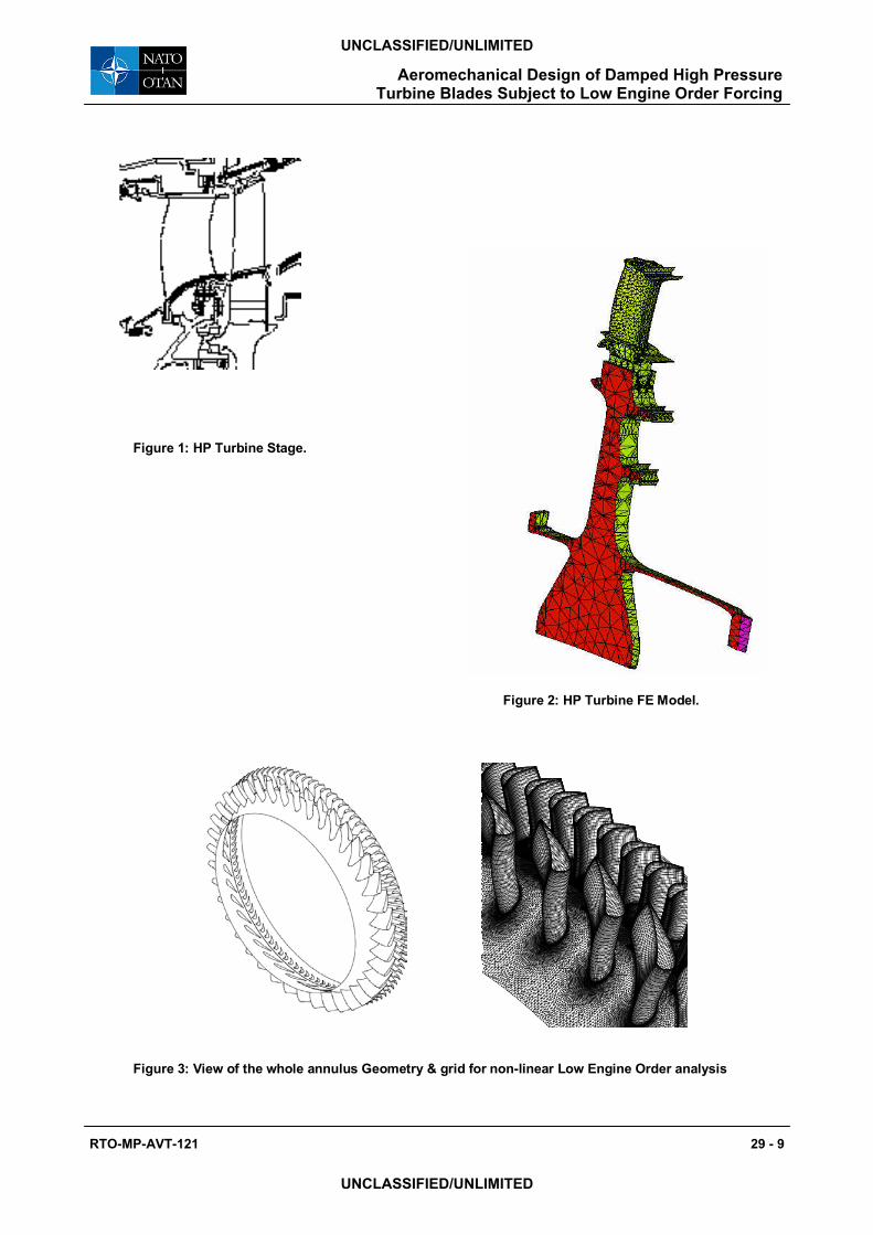
Figure 1: HP Turbine Stage.
Figure 2: HP Turbine FE Model.
Figure 3: View of the whole annulus Geometry & grid for non-linear Low Engine Order analysis
RTO-MP-AVT-121 29 - 9
UNCLASSIFIED/UNLIMITED
UNCLASSIFIED/UNLIMITED
Aeromechanical Design of Damped High Pressure Turbine Blades Subject to Low Engine Order Forcing
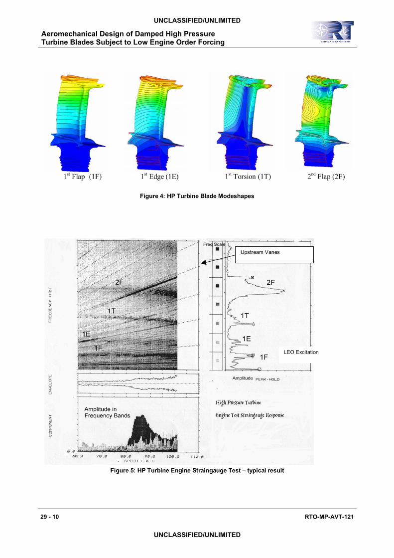
1st Flap (1F) 1st Edge (1E) 1st Torsion (1T) 2nd Flap (2F)
Figure 4: HP Turbine Blade Modeshapes
Figure 5: HP Turbine Engine Straingauge Test – typical result
LEO Excitation
Upstream Vanes
29 - 10 RTO-MP-AVT-121
UNCLASSIFIED/UNLIMITED
UNCLASSIFIED/UNLIMITED
Aeromechanical Design of Damped High Pressure Turbine Blades Subject to Low Engine Order Forcing
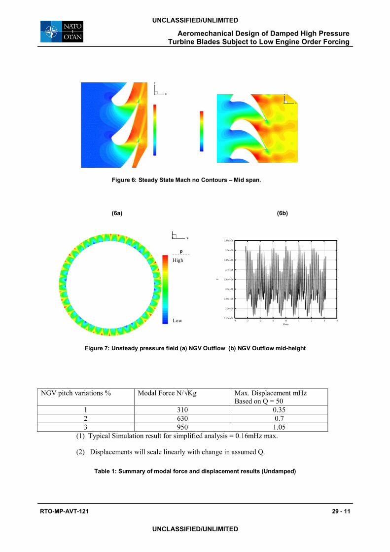
Figure 6: Steady State Mach no Contours – Mid span.
(6a) (6b)
Figure 7: Unsteady pressure field (a) NGV Outflow (b) NGV Outflow mid-height
NGV pitch variations % Modal Force N/√Kg Max. Displacement mHz Based on Q = 50
1 310 0.35 2 630 0.7 3 950 1.05
(1) Typical Simulation result for simplified analysis = 0.16mHz max.
(2) Displacements will scale linearly with change in assumed Q.
Table 1: Summary of modal force and displacement results (Undamped)
High Low
RTO-MP-AVT-121 29 - 11
UNCLASSIFIED/UNLIMITED
UNCLASSIFIED/UNLIMITED
Aeromechanical Design of Damped High Pressure Turbine Blades Subject to Low Engine Order Forcing
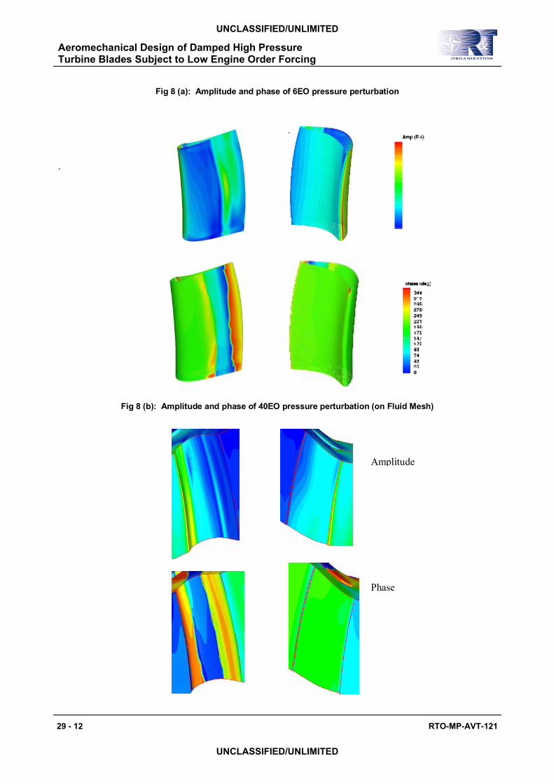
Fig 8 (a): Amplitude and phase of 6EO pressure perturbation
.
Fig 8 (b): Amplitude and phase of 40EO pressure perturbation (on Fluid Mesh)
Amplitude
Phase
29 - 12 RTO-MP-AVT-121
UNCLASSIFIED/UNLIMITED
UNCLASSIFIED/UNLIMITED
Aeromechanical Design of Damped High Pressure Turbine Blades Subject to Low Engine Order Forcing
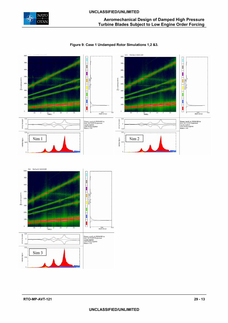
Figure 9: Case 1 Undamped Rotor Simulations 1,2 &3.
Sim 1 Sim 2
Sim 3
RTO-MP-AVT-121 29 - 13
UNCLASSIFIED/UNLIMITED
UNCLASSIFIED/UNLIMITED
Aeromechanical Design of Damped High Pressure Turbine Blades Subject to Low Engine Order Forcing
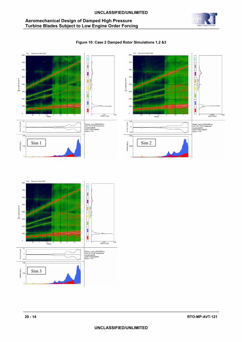
Figure 10: Case 2 Damped Rotor Simulations 1,2 &3
.
Sim 1 Sim 2
Sim 3
29 - 14 RTO-MP-AVT-121
UNCLASSIFIED/UNLIMITED
UNCLASSIFIED/UNLIMITED
Aeromechanical Design of Damped High Pressure Turbine Blades Subject to Low Engine Order Forcing
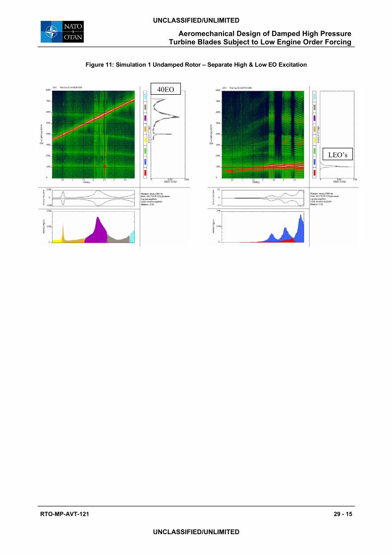
Figure 11: Simulation 1 Undamped Rotor – Separate High & Low EO Excitation
40EO
LEO’s
RTO-MP-AVT-121 29 - 15
UNCLASSIFIED/UNLIMITED
UNCLASSIFIED/UNLIMITED
Aeromechanical Design of Damped High Pressure Turbine Blades Subject to Low Engine Order Forcing

Aeromechanical Design of Damped High Pressure Turbine Blades Subject to Low Engine Order Forcing
29 - 16 RTO-MP-AVT-121
UNCLASSIFIED/UNLIMITED
UNCLASSIFIED/UNLIMITED