Embed Size (px)
Citation preview
JID:AESCTE AID:3633 /FLA [m5G; v1.175; Prn:12/04/2016; 12:55] P.1 (1-10)
Aerospace Science and Technology ••• (••••) •••–•••
1 67
2 68
3 69
4 70
5 71
6 72
7 73
8 74
9 75
10 76
11 77
12 78
13 79
14 80
15 81
16 82
17 83
18 84
19 85
20 86
21 87
22 88
23 89
24 90
25 91
26 92
27 93
28 94
29 95
30 96
31 97
32 98
33 99
34 100
35 101
36
37
38
39
40
41
42
43
44
45
46
47
48
49
50
51
52
53
54
55
56
57
58
59
60
61
62
63
64
65
66
Contents lists available at ScienceDirect
Aerospace Science and Technology
www.elsevier.com/locate/aescte
Attitude regulation for unmanned quadrotors using adaptive fuzzy
gain-scheduling sliding mode control
Yueneng Yang ∗, Ye Yan
College of Aerospace Science and Engineering, National University of Defense Technology, Changsha, 410073, China
a r t i c l e i n f o a b s t r a c t
Article history:Received 26 August 2015Received in revised form 13 March 2016Accepted 3 April 2016Available online xxxx
Keywords:Attitude controlSliding mode controlFuzzy rulesGain schedulingRobustnessQuadrotor
This paper addresses the problem of attitude regulation for unmanned quadrotors with parametric uncertainties and external disturbances. A novel adaptive fuzzy gain-scheduling sliding mode control (AFGS-SMC) approach is proposed for attitude regulation of unmanned quadrotors. First, the kinematics model and dynamics model of attitude motion are derived, and the problem of attitude regulation is formulated. Second, a sliding mode controller is designed to regulate the attitude motion for its invariant properties to parametric uncertainties and external disturbances. The global stability and error convergence of the closed-loop system are proven by using the Lyapunov stability theorem. In order to reduce the chattering induced by continual switching control of SMC, the fuzzy logic system (FLS) is employed to design the AFGS-SMC, in which the control gains related to sign function are scheduled adaptively according to fuzzy rules, with sliding surface and its differential as FLS inputs and control gains as FLS outputs. Finally, the effectiveness and robustness of the proposed control approach are demonstrated via simulation results.
© 2016 Published by Elsevier Masson SAS.
102
103
104
105
106
107
108
109
110
111
112
113
114
115
116
117
118
119
120
121
122
123
124
125
126
127
128
129
1. Introduction
As a type of unmanned rotorcraft, quadrotors are emerging as a kind of unique and promising platform for numerous tasks, such as reconnaissance, surveillance, environment monitoring, earth ob-servation, rescue operations and aerial photography, owing to their simple structure, their ability to hover, vertical takeoff, and land-ing capability [1–4]. These applications require good flight control capabilities, especially attitude regulation during hovering [5–7]. However, the difficulty of controller design increases due to the dynamic nonlinearity, parametric uncertainty and external distur-bances. This problem has received special attention from flight control researchers and engineers.
Various studies have been conducted to address the problem. Linear control method is the most widely used method, owing to its straightforward design and implementation procedures. Wang SH designed a double-gain proportional–differential (PD) controller to stabilize attitude dynamics of a quadrotor, and verified effective-ness of the proposed controller via flight experiments [8]. Su JY de-veloped a proportional-integral-derivative (PID) attitude controller
* Corresponding author at: Institute of Aerospace Technology, College of Aerospace Science and Engineering, National University of Defense Technology, Sany Road, Kaifu District, Changsha 410073, China. Tel.: +86 13548676452; fax: +86 073184573187.
E-mail address: [email protected] (Y. Yang).
http://dx.doi.org/10.1016/j.ast.2016.04.0051270-9638/© 2016 Published by Elsevier Masson SAS.
for a quadrotor [9]. However, PID controller can’t ensure closed-loop performance for different flight conditions. Ma ZH adopted the backstepping control approach to solve the problem of quadro-tor attitude stabilization. The attitude control system was divided into three second-order subsystems and each subsystem was de-signed by using integral backstepping control approach [10]. The controllers in references [8–10] were all developed based on the linear dynamics model, neglecting inherent nonlinearity of atti-tude dynamics. Based on the nonlinear dynamics model, Yilmaz designed an attitude controller for quadrotors by using nonlinear dynamic inversion [11]. The proposed control method is a sub-set of feedback linearization methods, and can be regarded as a tool to control the nonlinear dynamics system as if it is linear. Wang J presented a double-loop controller using dynamic inver-sion for quadrotors [12]. This approach is capable of decoupling the coupled dynamics of the quadcopter. Based on a nonlinear model with the quaternion representation, Liu proposed a state feedback controller for robotic quadrotors to restrain the effects of nonlinearities and uncertainties [13]. The SMC is an attractive control method for flight controller design owing to its robustness against uncertainties, insensitivity to the bounded disturbances and good transient performance. Patel employed the SMC to design the flight controller for a fully-actuated subsystem of a quadrotor [14]. The perturbation of system parameters of quadrotors brings difficulty to attitude control design; and therefore, the adaptive control method is adopted to estimate the time-varying parame-
130
131
132
JID:AESCTE AID:3633 /FLA [m5G; v1.175; Prn:12/04/2016; 12:55] P.2 (1-10)
2 Y. Yang, Y. Yan / Aerospace Science and Technology ••• (••••) •••–•••
1 67
2 68
3 69
4 70
5 71
6 72
7 73
8 74
9 75
10 76
11 77
12 78
13 79
14 80
15 81
16 82
17 83
18 84
19 85
20 86
21 87
22 88
23 89
24 90
25 91
26 92
27 93
28 94
29 95
30 96
31 97
32 98
33 99
34 100
35 101
36 102
37 103
38 104
39 105
40 106
41 107
42 108
43 109
44 110
45 111
46 112
47 113
48 114
49 115
50 116
51 117
52 118
53 119
54 120
55 121
56 122
57 123
58 124
59 125
60 126
61 127
62 128
63 129
64 130
65 131
66 132
ters. Dief designed an adaptive attitude controller for a small scale quadrotor. The basic idea of the designed controller is to estimate the open loop transfer function parameters online [15]. Through this estimation, the system dynamics and control gains can be up-dated adaptively. Lee designed a robust attitude tracking controller for quadrotors by adopting a nonlinear disturbance observer (DOB) [16]. The lumped disturbance is estimated by the DOB and the controller is designed using the estimate of disturbance. Mallikar-junan applied the L1 adaptive control theory to design the attitude controller for quadrotors. Simulation results illustrate that the de-signed controller is robust against model uncertainties and envi-ronmental disturbances [17]. Although these research works are useful for reference, the problem of attitude regulation still needs further attention and improvement, especially for the nonlinear dynamics, inertial uncertainties and external disturbances.
Motivated by the above studies, the current paper proposed an AFGS-SMC to address the problem of attitude regulation for quadrotors. In order to deal with inertial uncertainties and ex-ternal disturbances, the sliding mode control (SMC) represents an attractive alternative, and the control approach is employed in this work. The main feature of SMC is that it uses a high-speed switching control law to drive the system states from any initial state on the user specified surface in the state space (switching surface), and to maintain the states on the surface for all sub-sequent time [18,19]. SMC is well known for its invariant prop-erties to parameter variations and external disturbances, and has been widely applied to aircraft control design [20–25]. However, one major drawback of SMC is the chattering problem (high fre-quency of control action). This problem may excite unmodelled high-frequency dynamics, which in turn causes controller perfor-mance degradation [26]. There exist many methods for reducing the chattering phenomenon. One of the most common solutions to chattering problem is the boundary layer method. However, it has two main drawbacks [27–29]: the boundary layer thickness has the trade-off relation between control performances of controller and chattering migration, and the characteristics of robustness and the accuracy of the system are no longer assured. Another com-mon solution is the higher order SMC. It preserves the features of the first-order SMC and further improves its chattering reduc-tion and convergence speed. However, it is complex and requires the knowledge about the system’s uncertainty bounds. Facing these challenges, researchers are looking for new ways to approach these complex problems.
The information-based control theory and methodologies have emerged and attracted more and more attention in control com-munity [30,31], and have acted as alternatives to model-based methods. They are much suited for complicated control systems, whose mathematical models cannot be established, or for cases that the system models are too complicated to be effectively used. In general, information-based control methods can be di-vided into two categories: the indirect approaches and the direct approaches [32]. The second category consists of intelligent control methods, such as fuzzy logic control methods and neural network control methods. Compared with model-based control methods, information-based control methods do not have any special re-quirements on the system model structure and thus have attracted extensive attention. The fuzzy logic control, provide an effective approach to modify SMC with respect to chattering phenomenon. In contrast to mathematical models, fuzzy models can be devel-oped based on process input and output data without knowledge of the explicit model [33–35]. It is an ideal solution for nonlinear control where one does not know the rules or laws governing the relationships between the process inputs and outputs.
In this paper, the conventional SMC control has been modified in the following way: the switching gain of SMC is adapted on-line. The FLS is used to construct the AFGS-SMC. It is designed
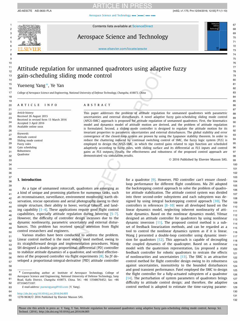
Fig. 1. The quadrotor configuration.
in such a way that the control gains related to the sign function are scheduled adaptively according to the designed fuzzy rules, with sliding surface and its differential as FLS inputs and control gains as FLS outputs. The modification successfully overcomes the problem of chattering phenomenon owing to the self-scheduling switching gain and continuous control law. This is an important advantage of an information-based controller in practical applica-tion.
Compared to previous studies on PID control [8,9] and back-stepping control [10], the proposed control approach increases the robustness of the controller with respect to parametric uncer-tainties and external disturbances. Compared to conventional SMC [14], the proposed control approach effectively eliminates chatter-ing phenomenon and obtained a good dynamic response. Com-pared to boundary layer SMC [27,28] and higher order SMC, the control approach can schedule the control gains adaptively based on the information of sliding surfaces.
The contributions of this paper could be briefly summarized as follows.
1) An effective and robust attitude controller is developed for unmanned quadrotor with parametric uncertainties and external disturbances.
2) A FLS is designed to schedule the switching gains adaptively according to the fuzzy rules based on the information of sliding surface, which eliminates chattering phenomenon effectively and obtained a good dynamic response.
The rest of this paper is organized as follows. In section 2, the kinematics model and dynamics model of attitude motion of quadrotors are formulated. In section 3, we designed the SMC and AFGS-SMC to address the problem of attitude regulation. In section 4, simulation studies illustrate the performance of the pro-posed control approach. Finally, conclusions are given in Section 5.
2. Modeling for the quadrotor
2.1. Quadrotor description
The quadrotor under consideration consists of four rotors in cross configuration, as shown in Fig. 1. The four rotors are desig-nated as rotor 1, 2, 3 and 4. Each two opposite rotors rotate in the same direction: the front and back rotors, labeled as rotor 1 and 3, rotate in the counterclockwise direction, and the right and left ro-tors, labeled as 2 and 4, rotate in the clockwise direction [5,36]. The four rotors can produce the desired forces and moments by increasing or decreasing the rotating speed, and they can be used in unison to control the attitude motion. The vertical ascend/de-scend can be adjusted by increasing or decreasing the speed of all the rotors. The pitch moment is generated by changing the rotor speed in 1 and 3, the yaw moment depends on the speed of all the rotors, and the roll moment is adjusted by changing the speed in rotor 2 and rotor 4 [5–7].
JID:AESCTE AID:3633 /FLA [m5G; v1.175; Prn:12/04/2016; 12:55] P.3 (1-10)
Y. Yang, Y. Yan / Aerospace Science and Technology ••• (••••) •••–••• 3
1 67
2 68
3 69
4 70
5 71
6 72
7 73
8 74
9 75
10 76
11 77
12 78
13 79
14 80
15 81
16 82
17 83
18 84
19 85
20 86
21 87
22 88
23 89
24 90
25 91
26 92
27 93
28 94
29 95
30 96
31 97
32 98
33 99
34 100
35 101
36 102
37 103
38 104
39 105
40 106
41 107
42 108
43 109
44 110
45 111
46 112
47 113
48 114
49 115
50 116
51 117
52 118
53 119
54 120
55 121
56 122
57 123
58 124
59 125
60 126
61 127
62 128
63 129
64 130
65 131
66 132
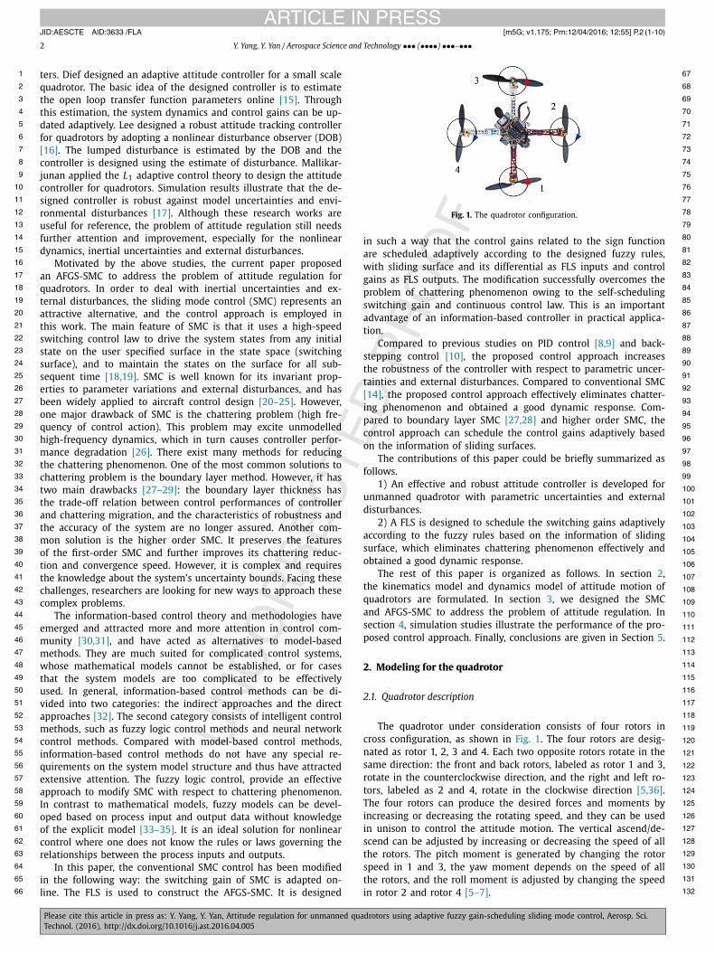
Fig. 2. Coordinate frames and motion variables of the quadrotor.
2.2. Kinematics and dynamics equations of attitude motion
Two coordinate frames are used to study the quadrotor mo-tion, as depicted in Fig. 2, the earth-fixed frame (frame E) oexe ye ze and the body-fixed frame (frame B) obxb yb zb . The po-sition of the quadrotor with respect to the frame E is described by P = [x, y, z]T , and the attitude of the quadrotor is described by Ω = [θ, ψ, φ]T , which are respectively called pitch angle (rotation around y-axis), yaw angle (rotation around z-axis) and roll angle (rotation around x-axis). Let v = [u, v, w]T denote the linear ve-locities, namely, the forward velocity, lateral velocity and vertical velocity; and ω = [p, q, r]T denote the angular velocities expressed in the frame B, namely, the rolling angular velocity, pitching angu-lar velocity and yawing angular velocity.
According to the relationship between the attitude angles and angular velocity, the kinematical equation of the quadrotor can be written as [5,6]:
Ω = J (Ω)ω (1)
where
J (Ω) =⎡⎣
0 cosφ − sin φ
0 sec θ sinφ sec θ cosφ
1 tan θ sinφ tan θ cosφ
⎤⎦ (2)
The dynamics equation of attitude motion can be derived from the Euler formulation, which can be expressed as follows [9]:
Iω + ω × (Iω) = τ (3)
where I = diag(Ix, I y, Iz), Ix , I y and Iz are the moments of iner-tia about the axis obxb , ob yb and ob zb , respectively; τ = [L, M, N]T
represents the control torques, L, M and N are the roll torque, pitch torque and yaw torque, respectively. The relationship be-tween the control inputs and the rotation speeds of the four pro-pellers can be approximated by [6,7]⎧⎪⎨⎪⎩
L = bl(n2
4 − n22
)
M = bl(n2
3 − n21
)
N = d(n2
2 − n21 + n2
4 − n23
) (4)
where b, d represent the lift and drag factors, and l represents the distance between the rotation axis of two opposite propellers, and n1, n2, n3 and n4 are the rotation speed of front rotor, right rotor, back rotor and left rotor respectively.
Fig. 3. The block diagram of SMC.
Considering the inertial uncertainty and external disturbance, the dynamics equation (3) can be rewritten as
(I + �I)ω = −ω × (I + �I)ω + τ + τ d (5)
where �I denotes the inertial uncertainties and τ d represents the external disturbances.
3. Control design for attitude regulation
3.1. Statement of control problem
The control objective is to design a controller that stabilizes the attitude error dynamics, the error between the referenced atti-tude and the actual attitude. The referenced equilibrium attitude is given by Ωr = [θr, ψr, φr]T , and the actual attitude Ω = [θ, ψ, φ]T
is required to regulate to the referenced attitude asymptotically, i.e. lim
t→∞‖Ω − Ωr‖.
3.2. SMC design
This section developed a SMC for attitude regulation of the quadrotor. Firstly, the sliding surface is defined; secondly, the reaching law is chosen; thirdly, the switching control law is de-signed; finally, the error convergence and stability of the closed-loop system is proven. The block diagram of SMC for attitude reg-ulation is depicted in Fig. 3.
The detailed design of SMC is described as follows.
Algorithm 1 SMC.Input:
1) referenced Euler angles Ωr
2) actual attitude angles of the quadrotor Ω3) model parameters of the quadrotor
Output: The control inputs for attitude regulationStep 1: Definition of sliding surface:
a) Compute the control error e;b) Select the optional definite matrix c;c) Define the sliding surface s;
Step 2: Definition of the reaching law:a) Define the sign function of the sliding surface;b) Select the optional positive definite matrices λ and k;c) Define the reaching law s = −λs − k sign(s);
Step 3: Design of the control law:a) Compute the angular velocity ω;b) Compute the transformation matrix J (Ω);c) Design the control input τ .
Step 4: Proof of the closed-loop systema) Select a Lyapunov function candidate V ;b) Compute the differential of V ;c) Check the sign of the differential of V ;d) Analyze the convergence of control error e.
Step 5: TerminationIf the tolerance of control error is satisfied, terminate the algorithm and out-
put τ . Otherwise, go to step 1.
Step 1:Define the control error
e = Ωr − Ω (6)
JID:AESCTE AID:3633 /FLA [m5G; v1.175; Prn:12/04/2016; 12:55] P.4 (1-10)
4 Y. Yang, Y. Yan / Aerospace Science and Technology ••• (••••) •••–•••
1 67
2 68
3 69
4 70
5 71
6 72
7 73
8 74
9 75
10 76
11 77
12 78
13 79
14 80
15 81
16 82
17 83
18 84
19 85
20 86
21 87
22 88
23 89
24 90
25 91
26 92
27 93
28 94
29 95
30 96
31 97
32 98
33 99
34 100
35 101
36 102
37 103
38 104
39 105
40 106
41 107
42 108
43 109
44 110
45 111
46 112
47 113
48 114
49 115
50 116
51 117
52 118
53 119
54 120
55 121
56 122
57 123
58 124
59 125
60 126
61 127
62 128
63 129
64 130
65 131
66 132
and define the sliding surface as follows
s = e + ce (7)
where c = diag(c1, c2, c3), and ci (i = 1, 2, 3) is a designed positive number.
The differential of s is
s = e + ce (8)
Substituting (6), (1)–(3) into (8) yields
s = ce + e = ce + Ωr − J (Ω)ω − J (Ω)I−1
× (−ω × (Iω) + τ − ω × (�Iω) + τ d − �Iω)
(9)
Define
d(Ω,ω, t) = −ω × (�Iω) − �Iω + τ d (10)
Eq. (9) can be rewritten as
s = ce + Ωr − J (Ω)ω − J (Ω)I−1(−ω × (Iω) + τ + d)
(11)
Assumption 1. The external disturbances are assumed to be bounded
∥∥d(Ω,ω, t)∥∥ ≤ D (12)
where D is a positive variable.
Step 2:Choose the following exponential reaching law [15,27]:
s = −λs − k sign(s) (13)
where λ and k are both diagonal positive definite matrices, with λ = diag(λ1, λ2, λ3), and λi (i = 1, 2, 3) which is a designed pos-itive number, as well as k = diag(k1, k2, k3), and ki (i = 1, 2, 3)
which is a designed positive number, and sign(·) denotes the sign function.
Step 3:With the consideration of sliding surface (7) and exponential
reaching law (13), the switching control law is designed as follows
τ = ω × (Iω) + I J −1(Ω)(λs + k sign(s) + ce + Ωr − J (Ω)ω
)
(14)
Step 4:The stability and error convergence of the closed-loop system
is proven as follows.
Theorem 1. For the nonlinear system (5), if the sliding surface is chosen as (7), and the control law is designed as (14), then it can guarantee the stability of the close-loop system, and the control errors converge to zero.
Proof. Select the following Lyapunov function candidate:
V = 1
2sT s (15)
Differentiating (15) with respect to time and using (11), we ob-tain
V = sT s
= sT {ce + Ωr − J (Ω)ω − J (Ω)I−1(−ω × (Iω) + τ + d
)}
(16)
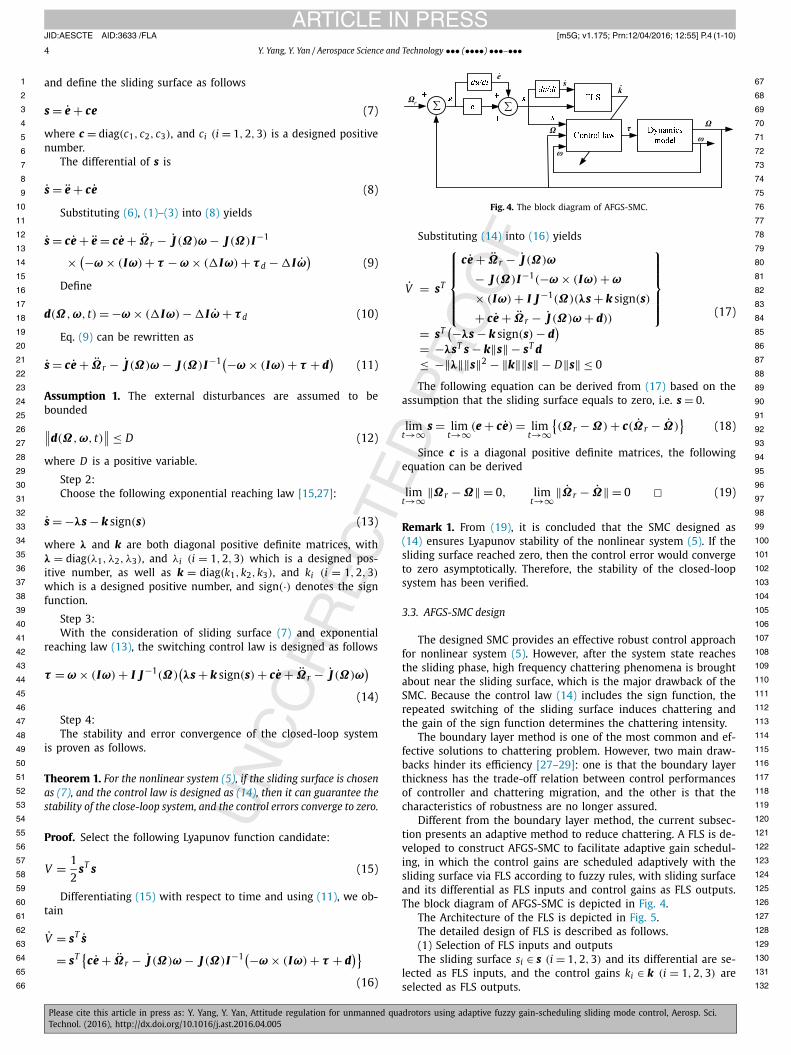
Fig. 4. The block diagram of AFGS-SMC.
Substituting (14) into (16) yields
V = sT
⎧⎪⎪⎪⎪⎨⎪⎪⎪⎪⎩
ce + Ωr − J (Ω)ω
− J (Ω)I−1(−ω × (Iω) + ω
× (Iω) + I J −1(Ω)(λs + k sign(s)
+ ce + Ωr − J (Ω)ω + d))
⎫⎪⎪⎪⎪⎬⎪⎪⎪⎪⎭
= sT(−λs − k sign(s) − d
)= −λsT s − k‖s‖ − sT d≤ −‖λ‖‖s‖2 − ‖k‖‖s‖ − D‖s‖ ≤ 0
(17)
The following equation can be derived from (17) based on the assumption that the sliding surface equals to zero, i.e. s = 0.
limt→∞ s = lim
t→∞(e + ce) = limt→∞
{(Ωr − Ω) + c(Ωr − Ω)
}(18)
Since c is a diagonal positive definite matrices, the following equation can be derived
limt→∞‖Ωr − Ω‖ = 0, lim
t→∞‖Ωr − Ω‖ = 0 � (19)
Remark 1. From (19), it is concluded that the SMC designed as (14) ensures Lyapunov stability of the nonlinear system (5). If the sliding surface reached zero, then the control error would converge to zero asymptotically. Therefore, the stability of the closed-loop system has been verified.
3.3. AFGS-SMC design
The designed SMC provides an effective robust control approach for nonlinear system (5). However, after the system state reaches the sliding phase, high frequency chattering phenomena is brought about near the sliding surface, which is the major drawback of the SMC. Because the control law (14) includes the sign function, the repeated switching of the sliding surface induces chattering and the gain of the sign function determines the chattering intensity.
The boundary layer method is one of the most common and ef-fective solutions to chattering problem. However, two main draw-backs hinder its efficiency [27–29]: one is that the boundary layer thickness has the trade-off relation between control performances of controller and chattering migration, and the other is that the characteristics of robustness are no longer assured.
Different from the boundary layer method, the current subsec-tion presents an adaptive method to reduce chattering. A FLS is de-veloped to construct AFGS-SMC to facilitate adaptive gain schedul-ing, in which the control gains are scheduled adaptively with the sliding surface via FLS according to fuzzy rules, with sliding surface and its differential as FLS inputs and control gains as FLS outputs. The block diagram of AFGS-SMC is depicted in Fig. 4.
The Architecture of the FLS is depicted in Fig. 5.The detailed design of FLS is described as follows.(1) Selection of FLS inputs and outputsThe sliding surface si ∈ s (i = 1, 2, 3) and its differential are se-
lected as FLS inputs, and the control gains ki ∈ k (i = 1, 2, 3) are selected as FLS outputs.
JID:AESCTE AID:3633 /FLA [m5G; v1.175; Prn:12/04/2016; 12:55] P.5 (1-10)
Y. Yang, Y. Yan / Aerospace Science and Technology ••• (••••) •••–••• 5
1 67
2 68
3 69
4 70
5 71
6 72
7 73
8 74
9 75
10 76
11 77
12 78
13 79
14 80
15 81
16 82
17 83
18 84
19 85
20 86
21 87
22 88
23 89
24 90
25 91
26 92
27 93
28 94
29 95
30 96
31 97
32 98
33 99
34 100
35 101
36 102
37 103
38 104
39 105
40 106
41 107
42 108
43 109
44 110
45 111
46 112
47 113
48 114
49 115
50 116
51 117
52 118
53 119
54 120
55 121
56 122
57 123
58 124
59 125
60 126
61 127
62 128
63 129
64 130
65 131
66 132
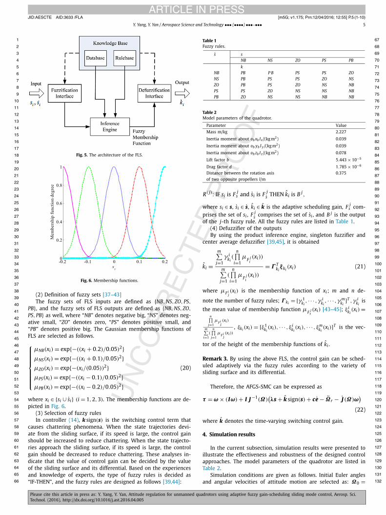
Fig. 5. The architecture of the FLS.
Fig. 6. Membership functions.
(2) Definition of fuzzy sets [37–43]The fuzzy sets of FLS inputs are defined as {NB, NS, ZO, PS,
PB}, and the fuzzy sets of FLS outputs are defined as {NB, NS, ZO,
PS, PB} as well, where “NB” denotes negative big, “NS” denotes neg-ative small, “ZO” denotes zero, “PS” denotes positive small, and “PB” denotes positive big. The Gaussian membership functions of FLS are selected as follows.
⎧⎪⎪⎪⎪⎪⎪⎨⎪⎪⎪⎪⎪⎪⎩
μNB(xi) = exp{−((xi + 0.2)/0.05)2}μNS(xi) = exp{−((xi + 0.1)/0.05)2}μZO(xi) = exp{−(xi/(0.05))2}μPS(xi) = exp{−((xi − 0.1)/0.05)2}μPB(xi) = exp{−((xi − 0.2)/0.05)2}
(20)
where xi ∈ {si ∪ si} (i = 1, 2, 3). The membership functions are de-picted in Fig. 6.
(3) Selection of fuzzy rulesIn controller (14), k sign(s) is the switching control term that
causes chattering phenomena. When the state trajectories devi-ate from the sliding surface, if its speed is large, the control gain should be increased to reduce chattering. When the state trajecto-ries approach the sliding surface, if its speed is large, the control gain should be decreased to reduce chattering. These analyses in-dicate that the value of control gain can be decided by the value of the sliding surface and its differential. Based on the experiences and knowledge of experts, the type of fuzzy rules is decided as “IF-THEN”, and the fuzzy rules are designed as follows [39,44]:
Table 1Fuzzy rules.
s sNB NS ZO PS PB
kNB PB P B PS PS ZONS PB PS PS ZO NSZO PB PS ZO NS NBPS PS ZO NS NS NBPB ZO NS NS NB NB
Table 2Model parameters of the quadrotor.
Parameter Value
Mass m/kg 2.227
Inertia moment about ob xb Ix/(kg m2) 0.039
Inertia moment about ob yb I y /(kg m2) 0.039
Inertia moment about ob zb Iz/(kg m2) 0.078
Lift factor b 5.443 × 10⁻⁵
Drag factor d 1.785 × 10⁻⁶
Distance between the rotation axis 0.375of two opposite propellers l/m
R( j): IF si is F js and si is F j
s THEN ki is B j,
where si ∈ s, si ∈ s, ki ∈ k is the adaptive scheduling gain, F js com-
prises the set of si , F js comprises the set of si , and B j is the output
of the j-th fuzzy rule. All the fuzzy rules are listed in Table 1.(4) Defuzzifier of the outputsBy using the product inference engine, singleton fuzzifier and
center average defuzzifier [39,45], it is obtained
ki =
m∑j=1
γ iki(
n∏i=1
μF j
i(xi))
m∑j=1
(n∏
i=1μ
F ji(xi))
= Γ Tkiξki
(xi) (21)
where μF ij(xi) is the membership function of xi ; m and n de-
note the number of fuzzy rules; Γ ki = [γ 1ki, · · · , γ i
ki, · · · , γ m
ki]T , γ i
kiis
the mean value of membership function μF j
s(xi) [43–45]; ξ i
ki(xi) =
n∏j=1
μF i
j(xi)
m∑i=1
(n∏
j=1μ
F ij(xi))
, ξki (xi) = [ξ1ki(xi), · · · , ξ i
ki(xi), · · · , ξm
ki(xi)]T is the vec-
tor of the height of the membership functions of ki .
Remark 3. By using the above FLS, the control gain can be sched-uled adaptively via the fuzzy rules according to the variety of sliding surface and its differential.
Therefore, the AFGS-SMC can be expressed as
τ = ω × (Iω) + I J −1(Ω)(λs + k sign(s) + ce − Ωr − J (Ω)ω
)
(22)
where k denotes the time-varying switching control gain.
4. Simulation results
In the current subsection, simulation results were presented to illustrate the effectiveness and robustness of the designed control approaches. The model parameters of the quadrotor are listed in Table 2.
Simulation conditions are given as follows. Initial Euler angles and angular velocities of attitude motion are selected as: Ω0 =
JID:AESCTE AID:3633 /FLA [m5G; v1.175; Prn:12/04/2016; 12:55] P.6 (1-10)
6 Y. Yang, Y. Yan / Aerospace Science and Technology ••• (••••) •••–•••
1 67
2 68
3 69
4 70
5 71
6 72
7 73
8 74
9 75
10 76
11 77
12 78
13 79
14 80
15 81
16 82
17 83
18 84
19 85
20 86
21 87
22 88
23 89
24 90
25 91
26 92
27 93
28 94
29 95
30 96
31 97
32 98
33 99
34 100
35 101
36 102
37 103
38 104
39 105
40 106
41 107
42 108
43
44
45
46
47
48
49
50
51
52
53
54
55
56
57
58
59
60
61
62
63
64
65
66
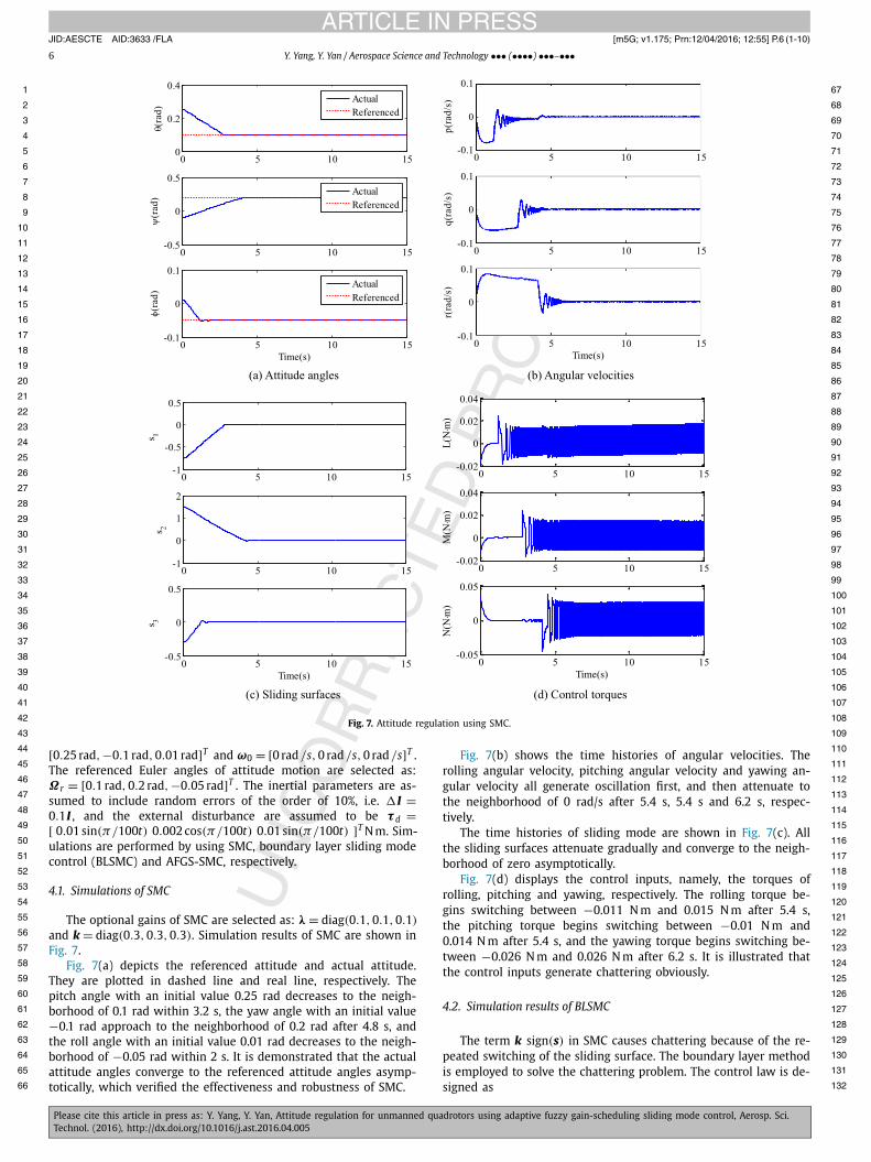
Fig. 7. Attitude regulation using SMC.
109110
111
112
113
114
115
116
117
118
119
120
121
122
123
124
125
126
127
128
129
130
131
132
[0.25 rad, −0.1 rad, 0.01 rad]T and ω0 = [0 rad /s, 0 rad/s, 0 rad/s]T . The referenced Euler angles of attitude motion are selected as: Ωr = [0.1 rad, 0.2 rad, −0.05 rad]T . The inertial parameters are as-sumed to include random errors of the order of 10%, i.e. �I =0.1I , and the external disturbance are assumed to be τ d =[ 0.01 sin(π/100t) 0.002 cos(π/100t) 0.01 sin(π/100t) ]T N m. Sim-ulations are performed by using SMC, boundary layer sliding mode control (BLSMC) and AFGS-SMC, respectively.
4.1. Simulations of SMC
The optional gains of SMC are selected as: λ = diag(0.1, 0.1, 0.1)
and k = diag(0.3, 0.3, 0.3). Simulation results of SMC are shown in Fig. 7.
Fig. 7(a) depicts the referenced attitude and actual attitude. They are plotted in dashed line and real line, respectively. The pitch angle with an initial value 0.25 rad decreases to the neigh-borhood of 0.1 rad within 3.2 s, the yaw angle with an initial value −0.1 rad approach to the neighborhood of 0.2 rad after 4.8 s, and the roll angle with an initial value 0.01 rad decreases to the neigh-borhood of −0.05 rad within 2 s. It is demonstrated that the actual attitude angles converge to the referenced attitude angles asymp-totically, which verified the effectiveness and robustness of SMC.
Fig. 7(b) shows the time histories of angular velocities. The rolling angular velocity, pitching angular velocity and yawing an-gular velocity all generate oscillation first, and then attenuate to the neighborhood of 0 rad/s after 5.4 s, 5.4 s and 6.2 s, respec-tively.
The time histories of sliding mode are shown in Fig. 7(c). All the sliding surfaces attenuate gradually and converge to the neigh-borhood of zero asymptotically.
Fig. 7(d) displays the control inputs, namely, the torques of rolling, pitching and yawing, respectively. The rolling torque be-gins switching between −0.011 N m and 0.015 N m after 5.4 s, the pitching torque begins switching between −0.01 N m and 0.014 N m after 5.4 s, and the yawing torque begins switching be-tween −0.026 N m and 0.026 N m after 6.2 s. It is illustrated that the control inputs generate chattering obviously.
4.2. Simulation results of BLSMC
The term k sign(s) in SMC causes chattering because of the re-peated switching of the sliding surface. The boundary layer method is employed to solve the chattering problem. The control law is de-signed as
JID:AESCTE AID:3633 /FLA [m5G; v1.175; Prn:12/04/2016; 12:55] P.7 (1-10)
Y. Yang, Y. Yan / Aerospace Science and Technology ••• (••••) •••–••• 7
1 67
2 68
3 69
4 70
5 71
6 72
7 73
8 74
9 75
10 76
11 77
12 78
13 79
14 80
15 81
16 82
17 83
18 84
19 85
20 86
21 87
22 88
23 89
24 90
25 91
26 92
27 93
28 94
29 95
30 96
31 97
32 98
33 99
34 100
35 101
36 102
37 103
38 104
39 105
40 106
41 107
42 108
43
44
45
46
47
48
49
50
51
52
53
54
55
56
57
58
59
60
61
62
63
64
65
66
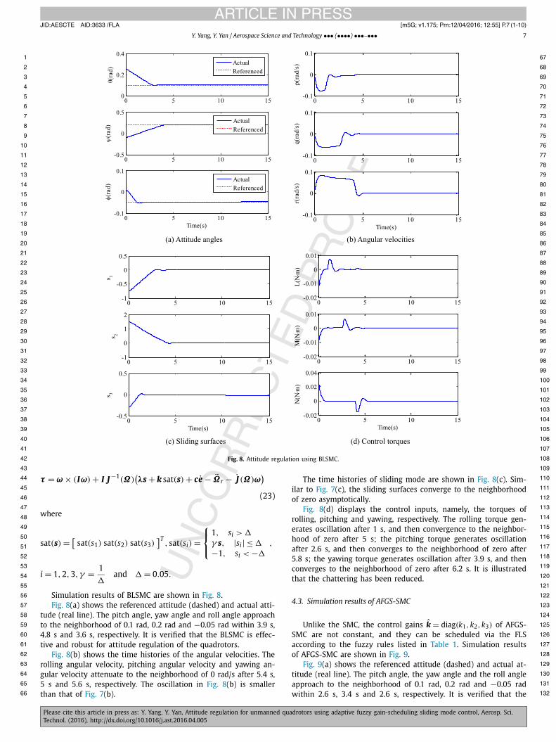
Fig. 8. Attitude regulation using BLSMC.
109110
111
112
113
114
115
116
117
118
119
120
121
122
123
124
125
126
127
128
129
130
131
132
τ = ω × (Iω) + I J −1(Ω)(λs + k sat(s) + ce − Ωr − J (Ω)ω
)
(23)
where
sat(s) = [sat(s1) sat(s2) sat(s3)
]T, sat(si) =
⎧⎨⎩
1, si > �
γ s, |si | ≤ �
−1, si < −�
,
i = 1,2,3, γ = 1
�and � = 0.05.
Simulation results of BLSMC are shown in Fig. 8.Fig. 8(a) shows the referenced attitude (dashed) and actual atti-
tude (real line). The pitch angle, yaw angle and roll angle approach to the neighborhood of 0.1 rad, 0.2 rad and −0.05 rad within 3.9 s, 4.8 s and 3.6 s, respectively. It is verified that the BLSMC is effec-tive and robust for attitude regulation of the quadrotors.
Fig. 8(b) shows the time histories of the angular velocities. The rolling angular velocity, pitching angular velocity and yawing an-gular velocity attenuate to the neighborhood of 0 rad/s after 5.4 s, 5 s and 5.6 s, respectively. The oscillation in Fig. 8(b) is smaller than that of Fig. 7(b).
The time histories of sliding mode are shown in Fig. 8(c). Sim-ilar to Fig. 7(c), the sliding surfaces converge to the neighborhood of zero asymptotically.
Fig. 8(d) displays the control inputs, namely, the torques of rolling, pitching and yawing, respectively. The rolling torque gen-erates oscillation after 1 s, and then convergence to the neighbor-hood of zero after 5 s; the pitching torque generates oscillation after 2.6 s, and then converges to the neighborhood of zero after 5.8 s; the yawing torque generates oscillation after 3.9 s, and then converges to the neighborhood of zero after 6.2 s. It is illustrated that the chattering has been reduced.
4.3. Simulation results of AFGS-SMC
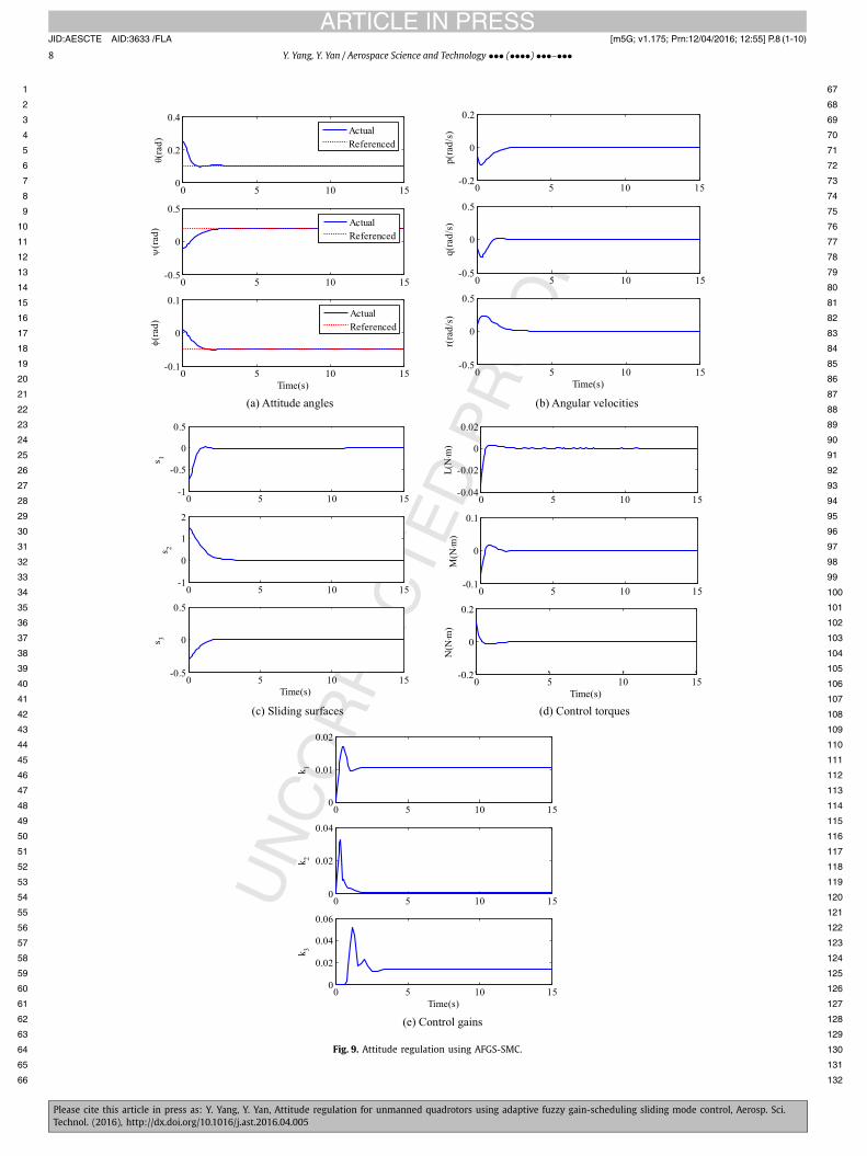
Unlike the SMC, the control gains k = diag(k1, k2, k3) of AFGS-SMC are not constant, and they can be scheduled via the FLS according to the fuzzy rules listed in Table 1. Simulation results of AFGS-SMC are shown in Fig. 9.
Fig. 9(a) shows the referenced attitude (dashed) and actual at-titude (real line). The pitch angle, the yaw angle and the roll angle approach to the neighborhood of 0.1 rad, 0.2 rad and −0.05 rad within 2.6 s, 3.4 s and 2.6 s, respectively. It is verified that the
JID:AESCTE AID:3633 /FLA [m5G; v1.175; Prn:12/04/2016; 12:55] P.8 (1-10)
8 Y. Yang, Y. Yan / Aerospace Science and Technology ••• (••••) •••–•••
1 67
2 68
3 69
4 70
5 71
6 72
7 73
8 74
9 75
10 76
11 77
12 78
13 79
14 80
15 81
16 82
17 83
18 84
19 85
20 86
21 87
22 88
23 89
24 90
25 91
26 92
27 93
28 94
29 95
30 96
31 97
32 98
33 99
34 100
35 101
36 102
37 103
38 104
39 105
40 106
41 107
42 108
43 109
44 110
45 111
46 112
47 113
48 114
49 115
50 116
51 117
52 118
53 119
54 120
55 121
56 122
57 123
58 124
59 125
60 126
61 127
62 128
63 129
64 130
65 131
66 132
Fig. 9. Attitude regulation using AFGS-SMC.
JID:AESCTE AID:3633 /FLA [m5G; v1.175; Prn:12/04/2016; 12:55] P.9 (1-10)
Y. Yang, Y. Yan / Aerospace Science and Technology ••• (••••) •••–••• 9
1 67
2 68
3 69
4 70
5 71
6 72
7 73
8 74
9 75
10 76
11 77
12 78
13 79
14 80
15 81
16 82
17 83
18 84
19 85
20 86
21 87
22 88
23 89
24 90
25 91
26 92
27 93
28 94
29 95
30 96
31 97
32 98
33 99
34 100
35 101
36 102
37 103
38 104
39 105
40 106
41 107
42 108
43 109
44 110
45 111
46 112
47 113
48 114
49 115
50 116
51 117
52 118
53 119
54 120
55 121
56 122
57 123
58 124
59 125
60 126
61 127
62 128
63 129
64 130
65 131
66 132
AFGS-SMC is effective and robust for attitude regulation of the quadrotors.
Fig. 9(b) shows the time histories of the angular velocities. The rolling angular velocity, pitching angular velocity and yawing an-gular velocity attenuate to the neighborhood of 0 rad/s after 5.2 s, 2.5 s and 5.2 s, respectively. Comparing to Fig. 7(b) and Fig. 8(b), the oscillation in Fig. 9(b) is much smaller.
The time histories of sliding mode are shown in Fig. 9(c). Sim-ilar to Fig. 7(c), the sliding surfaces convergence to the neighbor-hood of zero asymptotically.
Fig. 9(d) displays the control inputs, namely, the torques of rolling, pitching and yawing, respectively. In contrast to Fig. 7(d) and Fig. 8(d), the chattering is reduced effectively due to the use of FLS self-gain-scheduling approach. Fig. 9(e) depicts the time his-tories of control gains. In contrast to SMC and BLSMC, the control gains can be scheduled adaptively with the sliding surface and its differential via FLS according to the fuzzy rules.
Remark 3. 1) The SMC, BLSMC and AFGS-SMC are all effective and robust for attitude regulation in presence of inertial uncertainties and external disturbances. 2) The drawback of SMC is that the con-trol inputs generate chattering obviously. 3) The control gains of AFGS-SMC are scheduled adaptively with the sliding surface and its differential according to the designed fuzzy rules, which reduces the chattering effectively.
5. Conclusions
An AFGS-SMC approach is proposed to address the problem of attitude regulation for quadrotors. The kinematics model and dy-namics model of attitude motion of the quadrotor are derived first. Then, the design of SMC is described in detail and the stability of the closed-loop system is proven by using the Lyapunov stabil-ity theorem. In order to solve the chattering problem induced by switching control of SMC, a FLS is proposed to design AFGS-SMC to schedule the control gains adaptively according to fuzzy rules. Through the simulation results, the proposed control approach is demonstrated to be effective and robust for attitude regulation. Comparing results indicate that the AFGS-SMC has reduced the chattering and promoted control performance effectively.
Conflict of interest statement
None declared.
Acknowledgements
This work is supported by National Natural Science Foundation of China (No. 11502288), and the author is also deeply indebted to the editors and reviewers.
References
[1] F. Yacef, B. Omar, M. Hamerlain, Adaptive fuzzy backstepping control for tra-jectory tracking of unmanned aerial quadrotor, in: International Conference on Unmanned Aircraft Systems, Orlando, USA, 2014, pp. 920–927.
[2] O. Araar, N. Aouf, Quadrotor control for trajectory tracking in presence of wind disturbances, in: International Conference on Control, Loughborough, UK, 2014, pp. 25–30.
[3] T.C. Ton, K.S. McKinely, W. MacKunis, Robust tracking control of a quadrotor in the presence of uncertainty and non-vanishing disturbance, in: AIAA Guidance, Navigation, and Control Conference, Florida, USA, 2015.
[4] P. Niermeyer, T. Raery, F. Holzapfel, Open-loop quadrotor flight dynamics iden-tification in frequency domain via closed-loop flight testing, in: AIAA Guidance, Navigation, and Control Conference, Florida, USA, 2015.
[5] I.H. Choi, H.C. Bang, Quadrotor-tracking controller design using adaptive dy-namic feedback-linearization method, Proc. Inst. Mech. Eng., G J. Aerosp. Eng. 228 (12) (2014) 2329–2342.
[6] L. Sun, Z.Y. Zuo, Nonlinear adaptive trajectory tracking control for a quad-rotor with parametric uncertainty, Proc. Inst. Mech. Eng., G J. Aerosp. Eng. 229 (9) (2015) 1709–1721.
[7] X.S. Lei, P. Lu, F. Liu, The nonlinear disturbance observer-based control for small rotary-wing unmanned aircraft, Proc. Inst. Mech. Eng., G J. Aerosp. Eng. 228 (12) (2014) 2168–2177.
[8] S.H. Wang, Y. Yang, Quadrotor aircraft attitude estimation and control based on Kalman filter, Control Theory Appl. 30 (9) (2013) 1110–1115.
[9] J.Y. Su, P.H. Fan, K.Y. Cai, Attitude control of quadrotor aircraft via nonlinear PID, J. Beijing Univ. Aeronaut. Astronaut. 37 (9) (2011) 1054–1058.
[10] Z.H. Ma, Q.Q. Zhang, L.P. Chen, Attitude control of quadrotor aircraft via adap-tive back-stepping control, CAAI Trans. Intell. Syst. 10 (3) (2015) 1–7.
[11] E. Yilmaz, T.A. Kutay, Adaptive robust attitude controller design for a quadro-tor platform, in: AIAA Atmospheric Flight Mechanics Conference, Atlanta, USA, 2014.
[12] J. Wang, T. Bierling, M. Achtelik, Attitude free position control of a quadcopter using dynamic inversion, in: InfoTech Aerospace, Missouri, USA, 2011.
[13] H. Liu, X.F. Wang, Y.S. Zhong, Quaternion-based robust attitude control for un-certain robotic quadrotors, IEEE Trans. Ind. Inform. 11 (2) (2015) 402–415.
[14] A.R. Patel, M.A. Patel, D.R. Vyas, Modeling and analysis of quadrotor using sliding mode control, in: The 44th IEEE Southeastern Symposium on System Theory, Florida, USA, 2012.
[15] N.T. Dief, G.M. Abdelhady, Attitude and altitude stabilization of quad rotor using parameter estimation and self-tuning controller, in: AIAA Atmospheric Flight Mechanics Conference, Dallas, USA, 2015.
[16] K. Lee, J. Back, I. Choy, Nonlinear disturbance observer based robust attitude tracking controller for quadrotor UAVs, Int. J. Control. Autom. Syst. 12 (6) (2014) 1266–1275.
[17] S.M. Mallikarjunan, B. Nesbitt, E. Kharisov, L1 adaptive controller for attitude control of multirotors, in: AIAA Guidance, Navigation, and Control Conference, Minneapolis, Minnesota, USA, 2012.
[18] A. Nasirin, S.K. Nguang, A. Swain, Adaptive sliding mode control for a class of MIMO nonlinear systems with uncertainties, J. Franklin Inst. 351 (2014) 2048–2061.
[19] A.K. Khalaji, S.A. Moosavian, Adaptive sliding mode control of a wheeled mobile robot towing a trailer, Proc. Inst. Mech. Eng., Part I, J. Syst. Control Eng. 229 (2) (2015) 169–183.
[20] C. Pukdeboon, P. Kumam, Robust optimal sliding mode control for spacecraft position and attitude maneuvers, Aerosp. Sci. Technol. 43 (2015) 329–342.
[21] S.M. He, D.F. Lin, J. Wang, Continuous second-order sliding mode based impact angle guidance law, Aerosp. Sci. Technol. 41 (2015) 199–208.
[22] P.M. Tiwari, S. Janardhanan, M. Nabi, Rigid spacecraft attitude control using adaptive integral second order sliding mode, Aerosp. Sci. Technol. 42 (2015) 50–57.
[23] B.L. Tian, Q. Zong, J. Wang, F. Wang, Quasi-continuous high-order sliding mode controller design for reusable launch vehicles in reentry phase, Aerosp. Sci. Technol. 28 (1) (2013) 198–207.
[24] L.H. Liu, J.W. Zhu, G.J. Tang, W.M. Bao, Diving guidance via feedback lineariza-tion and sliding mode control, Aerosp. Sci. Technol. 41 (2015) 16–23.
[25] D.V. Rao, T.H. Go, Automatic landing system design using sliding mode control, Aerosp. Sci. Technol. 32 (1) (2014) 180–187.
[26] J. Huang, M.J. Liu, J. Zhang, High-order non-singular terminal sliding mode con-trol for dual-stage hard disk drive head positioning systems, Proc. Inst. Mech. Eng., Part I, J. Syst. Control Eng. 229 (3) (2013) 193–201.
[27] A. Rojko, K. Jezernik, Sliding-mode motion controller with adaptive fuzzy dis-turbance estimation, IEEE Trans. Ind. Electron. 51 (5) (2004) 963–971.
[28] M.L. Jin, J. Lee, P.H. Chang, C. Choi, Practical nonsingular terminal sliding-mode control of robot manipulators for high-accuracy tracking control, IEEE Trans. Ind. Electron. 56 (9) (2009) 3593–3601.
[29] M. Chen, Q.X. Wu, R.X. Cui, Terminal sliding mode tracking control for a class of SISO uncertain nonlinear systems, ISA Trans. 52 (2013) 198–206.
[30] S. Yin, O. Kaynak, Big data for modern industry: challenges and trends, Proc. IEEE 103 (2) (2015) 143–146.
[31] S. Yin, X.P. Zhu, O. Kaynak, Improved PLS focused on key-performance-indicator-related fault diagnosis, IEEE Trans. Ind. Electron. 62 (3) (2015) 1651–1658.
[32] Z. Wang, D.R. Liu, Data-based output feedback control using least squares esti-mation method for a class of nonlinear systems, Int. J. Robust Nonlinear Control 24 (2014) 3061–3075.
[33] S. Yin, Z.H. Huang, Performance monitoring for vehicle suspension system via fuzzy positivistic C-means clustering based on accelerometer measurements, IEEE/ASME Trans. Mechatron. 20 (5) (2015) 2613–2620.
[34] S. Yin, G. Wang, H.J. Gao, Data-driven process monitoring based on modified orthogonal projections to latent structures, IEEE Trans. Control Syst. Technol. PP 99 (2015) 1–8.
[35] S. Yin, P. Shi, H.Y. Yang, Adaptive fuzzy control of strict-feedback nonlin-ear time-delay systems with unmodeled dynamics, IEEE Trans. Cybern. PP 99 (2015) 1–12.
JID:AESCTE AID:3633 /FLA [m5G; v1.175; Prn:12/04/2016; 12:55] P.10 (1-10)
10 Y. Yang, Y. Yan / Aerospace Science and Technology ••• (••••) •••–•••
1 67
2 68
3 69
4 70
5 71
6 72
7 73
8 74
9 75
10 76
11 77
12 78
13 79
14
15
16
17
18
19
20
21
22
23
24
25
26
27
28
29
30
31
32
33
34
35
36
37
38
39
40
41
42
43
44
45
46
47
48
49
50
51
52
53
54
55
56
57
58
59
60
61
62
63
64
65
66
[36] R. Zawiski, M. Błachuta, Dynamics and optimal control of quadrotor platform, in: AIAA Guidance, Navigation, and Control Conference, Minnesota, USA, 2012.
[37] E. Mohammadi, M. Montazeri-Gh, A fuzzy-based gas turbine fault detection and identification system for full and part-load performance deterioration, Aerosp. Sci. Technol. 46 (2015) 82–93.
[38] N. Ullah, S.P. Wang, M.I. Khattak, M. Shafi, Fractional order adaptive fuzzy sliding mode controller for a position servo system subjected to aerodynamic loading and nonlinearities, Aerosp. Sci. Technol. 43 (2015) 381–387.
[39] J.M. Sánchez-Lozano, J. Serna, A. Dolón-Payán, Evaluating military training air-crafts through the combination of multi-criteria decision making processes with fuzzy logic, a case study in the Spanish Air Force Academy, Aerosp. Sci. Technol. 42 (2015) 58–65.
[40] A.M. Basri, A.R. Husain, A.K. Danapalasingam, A hybrid optimal backstepping and adaptive fuzzy control for autonomous quadrotor helicopter with time-varying disturbance, Proc. Inst. Mech. Eng., G J. Aerosp. Eng. (2015).
[41] S. Chang, H. Bang, W. Lee, B. Park, Dynamic modeling and fuzzy control for a small tiltrotor unmanned aerial vehicle, Proc. Inst. Mech. Eng., G J. Aerosp. Eng. 227 (9) (2013) 1468–1487.
[42] H.Y. Zhang, J. Wang, G.D. Lu, Self-organizing fuzzy optimal control for under-actuated systems, Proc. Inst. Mech. Eng., Part I, J. Syst. Control Eng. 228 (8) (2014) 578–590.
[43] A.F. Amer, E.A. Sallam, W.M. Elawady, Quasi sliding mode-based single input fuzzy self-tuning decoupled fuzzy PI control for robot manipulators with un-certainty, Int. J. Robust Nonlinear Control 22 (2014) 2026–2054.
[44] Y.S. Zhang, T. Yang, C.Y. Li, S.S. Liu, Fuzzy-PID control for the position loop of aerial inertially stabilized platform, Aerosp. Sci. Technol. 36 (2014) 21–26.
[45] H.M. Omar, Designing anti-swing fuzzy controller for helicopter slung-load system near hover by particle swarms, Aerosp. Sci. Technol. 29 (1) (2013) 223–234.
80
81
82
83
84
85
86
87
88
89
90
91
92
93
94
95
96
97
98
99
100
101
102
103
104
105
106
107
108
109
110
111
112
113
114
115
116
117
118
119
120
121
122
123
124
125
126
127
128
129
130
131
132