Embed Size (px)
Citation preview

Aesculap OrthopaedicsColumbus® MIOS™
Minimally Invasive Orthopaedic Solutions
Manual TKA Surgical Technique

“Columbus MIOS™, the manual solution to the challenges of minimally invasive surgery”
2
MIOS Tibial Left andRight Cutting Blocks
MIOS 4-in-1Cutting Block
MIOS DistalFemoral Cutting
Block

Contents
The MIOS™ Surgical Technique was developed in conjunctionwith:
S. David Stulberg, M.D., F.A.A.O.S.Professor Clinical Orthopaedic SurgeryNorthwestern University Feinberg School of MedicineDirector, Joint Reconstruction & Implant ServicesNorthwestern Memorial HospitalChicago, IL
Michael J. Fracchia, M.D., A.B.O.S., F.A.A.O.S.Director of Surgical Education, Aesculap USAPresident, Long Island Bone and JointDirector, Department of Orthopaedics, JT Mather Hospital
3
Introduction
Indication
Preoperative Planning
Columbus MIOS™ TKA Approach
Surgical Technique
Measured Resection Technique - Femur First
Gap Balancing Technique - Tibia First
Columbus Implant Sizes
Columbus Ordering Information
4
6
7
8
9
12
32
56
58

“Minimally invasive surgical techniques are currently beingdeveloped and evaluated for use in knee joint arthroplasty surgery.It is hoped that the reduction in soft tissue trauma that may beassociated with these approaches will improve functionaloutcomes, especially in the early post-operative period, reduceperi-operative morbidity, and accelerate post-operative recovery.The surgical exposures used for the various minimally invasivetechniques greatly reduce visualization of important anatomiclandmarks as compared to conventional exposures. As a result, anumber of techniques have been developed to deal with thereduction in visualization. These include the use of 1) “mobilewindows”; 2) special retractors; unique, downsized instruments; 4)alterations in surgical exposure; and 5) the use of multipleassistants. The consequences of reduced visualization include thepotential for implant mal-position, fractures, neurovascularinjuries, compromised wound healing, and prolonged operativetime. The precise implantation of arthroplasty components mayalso be difficult if the entire implantation surface is not visible.
This surgical technique is designed to outline the manual approachfor less invasive total knee arthroplasty. However, it is importantto recognize the value of computer-assisted surgical navigationwhen using a less invasive approach. Computer-assistedorthopaedic surgical navigation systems are now widely availableand are increasingly used to overcome the inherent limitations ofmanual instrumentation. These limitations are magnified whenminimally invasive exposures are used.
Introduction
4

The rationale for merging minimally invasive surgical techniqueswith computer-assisted orthopaedic navigation is that theaccuracy and reliability that is possible with the use ofcomputer-assisted techniques can be retained when less invasiveexposures are used. The results from a number of centers using avariety of image-free computer-assisted systems and conventionalsurgical exposures have indicated that the average limb alignmentachieved with these systems is as good or better than thatachieved with manual instruments, that the number of limbssignificantly mal-aligned (“outliers”) is reduced, and that thealignment of each of the arthroplasty components is moreaccurate. The increase in surgical time is often no more than 5-10minutes. The use of computer-assisted techniques also helped toemphasize the usefulness of measuring the accuracy of each stepof the surgical procedure.
The extraordinary interest by patients and surgeons in minimallyinvasive TKA approaches is a stimulus for the continued evolutionand merging of computer-assisted and minimally invasiveorthopaedic surgical technologies. The Columbus MIOS approachto less invasive knee arthroplasty from Aesculap Implant Systemseffectively combines less invasive surgical techniques,instrumentation, implant design, and computer-assistednavigation to help surgeons optimize surgical and clinicaloutcomes for total knee arthroplasty. The Columbus MIOS Manualtechnique is part of a comprehensive approach to the performanceof knee arthroplasty using less invasive surgical techniques.
S. David Stulberg, M.D.Professor of Clinical Orthopaedic SurgeryNorthwestern University Feinberg School of MedicineDirector, Joint Reconstruction and Implant ServicesNorthwestern Memorial HospitalChicago, IL
5

Indication
The Columbus MIOS manual surgical technique can be used inprimary TKA procedures in which minimally invasive or traditionalexposures are appropriate.
Contraindication
� Active infection, sepsis, and ostomyelitis
Relative Contraindications
� Patients who may be incapable of followingdirections
� Osteoporosis� Metabolic disorders which may affect bone
formation� Osteomalacia� Infections that may spread to the implant site� Vascular insufficiency, muscular atrophy, and
neuromuscular disease� Incomplete of deficient soft tissue surrounding
the knee� Marked bone loss or bone resorption apparent
on x-ray
Potential Advantages of a MinimallyInvasive Technique
� Less blood loss� Reduced swelling of the associated soft-tissues� Rapid wound healing� Improved Cosmesis� Reduced post-operative pain� Reduced hospital stay� Faster restoration of function
6
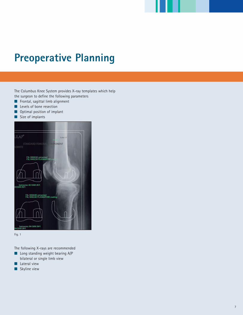
Preoperative Planning
The Columbus Knee System provides X-ray templates which help the surgeon to define the following parameters� Frontal, sagittal limb alignment� Levels of bone resection� Optimal position of implant� Size of implants
The following X-rays are recommended� Long standing weight bearing A/P
bilateral or single limb view� Lateral view � Skyline view
Fig. 1
STANDARD FEMORAL COMPONENTSTANDARD FEMORAL COMPONENTSTANDA STANDARD FEMORAL COMPONENT
Scale 1:1Scale 1:1
F3L: NN003K cementedF3L: NN003K cementedF3L: NN023K PLASMAPORE coatingF3L: NN023K PLASMAPORE coating
F3R: NN013K cemented F3R: NN013K cementedF3R: NN033K F3R: NN033K PLASMAPORE coating
Scale 1:1 Scale 1:1
F4L: NN004K cementedF4L: NN004K cementedF4L: NN024K PLASMAPORE coatingF4L: NN024K PLASMAPORE coating
F4R: NN014K cemented F4R: NN014K cementedF4R: NN034K F4R: NN034K PLASMAPORE coating
109
87
65
43
21
011
1213
1415
1617
18
CEN
TIM
ETER
S (S
cale
is e
nla
rged
to te
mp
late
mag
nifi
cati
on
)
cmcm
R
7
8
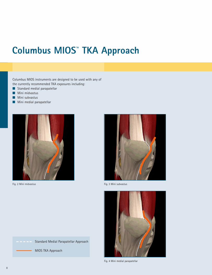
Columbus MIOS™ TKA Approach
Columbus MIOS instruments are designed to be used with any ofthe currently recommended TKA exposures including:� Standard medial parapatellar� Mini midvastus� Mini subvastus� Mini medial parapatellar
Fig. 2 Mini midvastus Fig. 3 Mini subvastus
Fig. 4 Mini medial parapatellar
Standard Medial Parapatellar Approach
MIOS TKA Approach
9
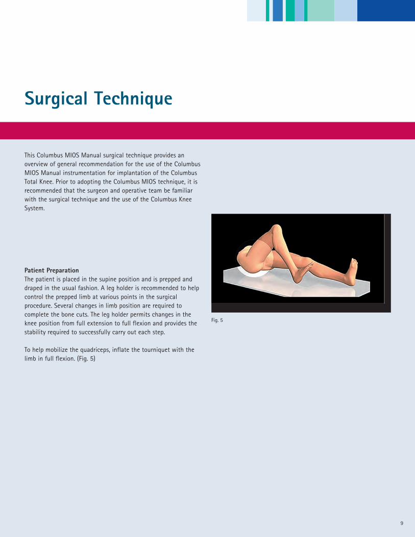
Patient PreparationThe patient is placed in the supine position and is prepped anddraped in the usual fashion. A leg holder is recommended to helpcontrol the prepped limb at various points in the surgicalprocedure. Several changes in limb position are required tocomplete the bone cuts. The leg holder permits changes in theknee position from full extension to full flexion and provides thestability required to successfully carry out each step.
To help mobilize the quadriceps, inflate the tourniquet with thelimb in full flexion. (Fig. 5)
Surgical Technique
Fig. 5
This Columbus MIOS Manual surgical technique provides anoverview of general recommendation for the use of the ColumbusMIOS Manual instrumentation for implantation of the ColumbusTotal Knee. Prior to adopting the Columbus MIOS technique, it isrecommended that the surgeon and operative team be familiarwith the surgical technique and the use of the Columbus KneeSystem.
Surgical Technique
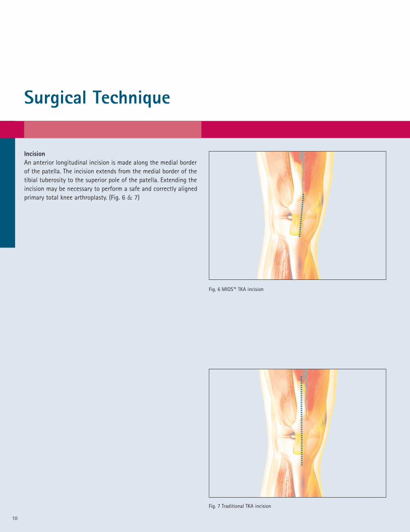
IncisionAn anterior longitudinal incision is made along the medial borderof the patella. The incision extends from the medial border of thetibial tuberosity to the superior pole of the patella. Extending theincision may be necessary to perform a safe and correctly alignedprimary total knee arthroplasty. (Fig. 6 & 7)
Fig. 6 MIOS™ TKA incision
Fig. 7 Traditional TKA incision
10
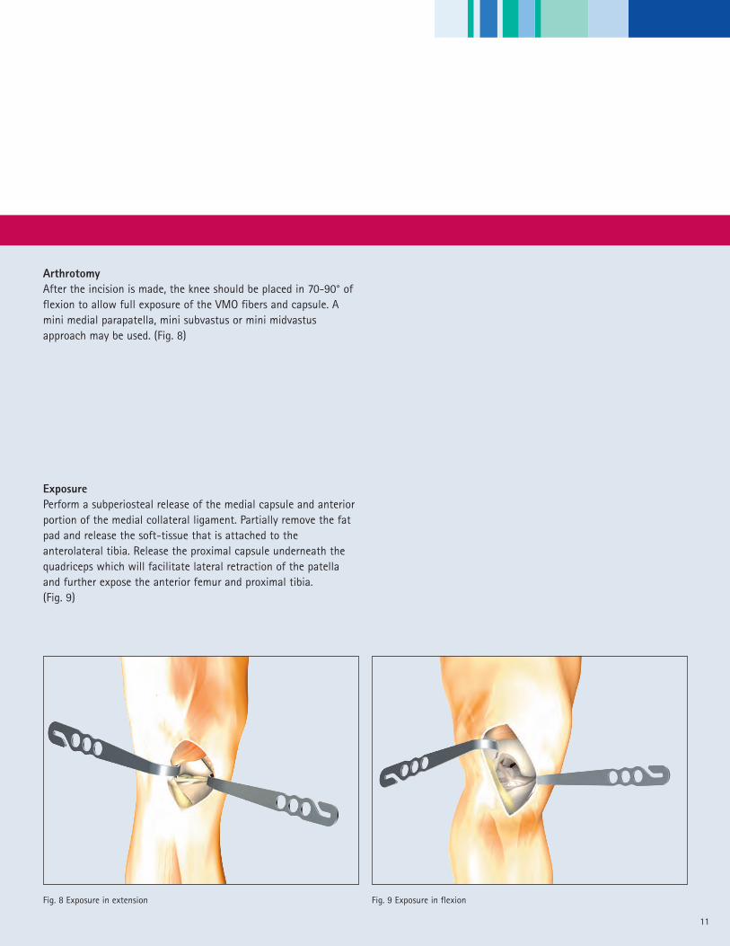
ArthrotomyAfter the incision is made, the knee should be placed in 70-90° offlexion to allow full exposure of the VMO fibers and capsule. Amini medial parapatella, mini subvastus or mini midvastusapproach may be used. (Fig. 8)
Fig. 8 Exposure in extension
ExposurePerform a subperiosteal release of the medial capsule and anteriorportion of the medial collateral ligament. Partially remove the fatpad and release the soft-tissue that is attached to theanterolateral tibia. Release the proximal capsule underneath thequadriceps which will facilitate lateral retraction of the patellaand further expose the anterior femur and proximal tibia.(Fig. 9)
Fig. 9 Exposure in flexion
11

12
Measured Resection Technique - Femur First
Preliminary Patella Cut (optional)Prior to preparation of the femur, the surgeon may choose to carryout the patella resection in order to improve distal femoralvisualization. The use of specially designed patella clamps will helpfacilitate control of the patella. The patella protection plateNQ943R is placed on the resected surface to help avoid damagethat may be caused during retraction or from other surgicalinstruments during the procedure. (Fig. 10)
The surgeon may also elect to resect the tibial spine at this pointto further improve visualization of the femur.
Identify Whiteside's Line (optional)For the purpose of establishing rotation of the femoral component,Whiteside’s line is identified and marked with a sterile marker.(Fig. 11)
Fig. 10
Fig. 11

13
Resection of the Distal FemurThe entry point of the femoral medullary cavity is opened with the9mm drill (NE443R). The 8mm intramedullary femoral rod(NQ475R) is introduced into the medullary cavity using the handleand the distal femoral alignment system (NQ470R). (Fig. 12)
Fig. 12
Fig. 13
The femoral cutting block (NQ471R) is then placed onto the deviceconnecting to the two stainless steel posts. This system offers thepossibility of varus/valgus adjustment in 1° intervals A . Theadjustment range extends to 11° (Fig. 13)
A
A
14
Measured Resection Technique - Femur First
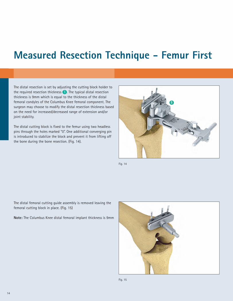
The distal resection is set by adjusting the cutting block holder tothe required resection thickness B . The typical distal resectionthickness is 9mm which is equal to the thickness of the distalfemoral condyles of the Columbus Knee femoral component. Thesurgeon may choose to modify the distal resection thickness basedon the need for increased/decreased range of extension and/orjoint stability.
The distal cutting block is fixed to the femur using two headlesspins through the holes marked “0”. One additional converging pinis introduced to stabilize the block and prevent it from lifting offthe bone during the bone resection. (Fig. 14).
Fig. 14
Fig. 15
The distal femoral cutting guide assembly is removed leaving thefemoral cutting block in place. (Fig. 15)
Note: The Columbus Knee distal femoral implant thickness is 9mm
B
15
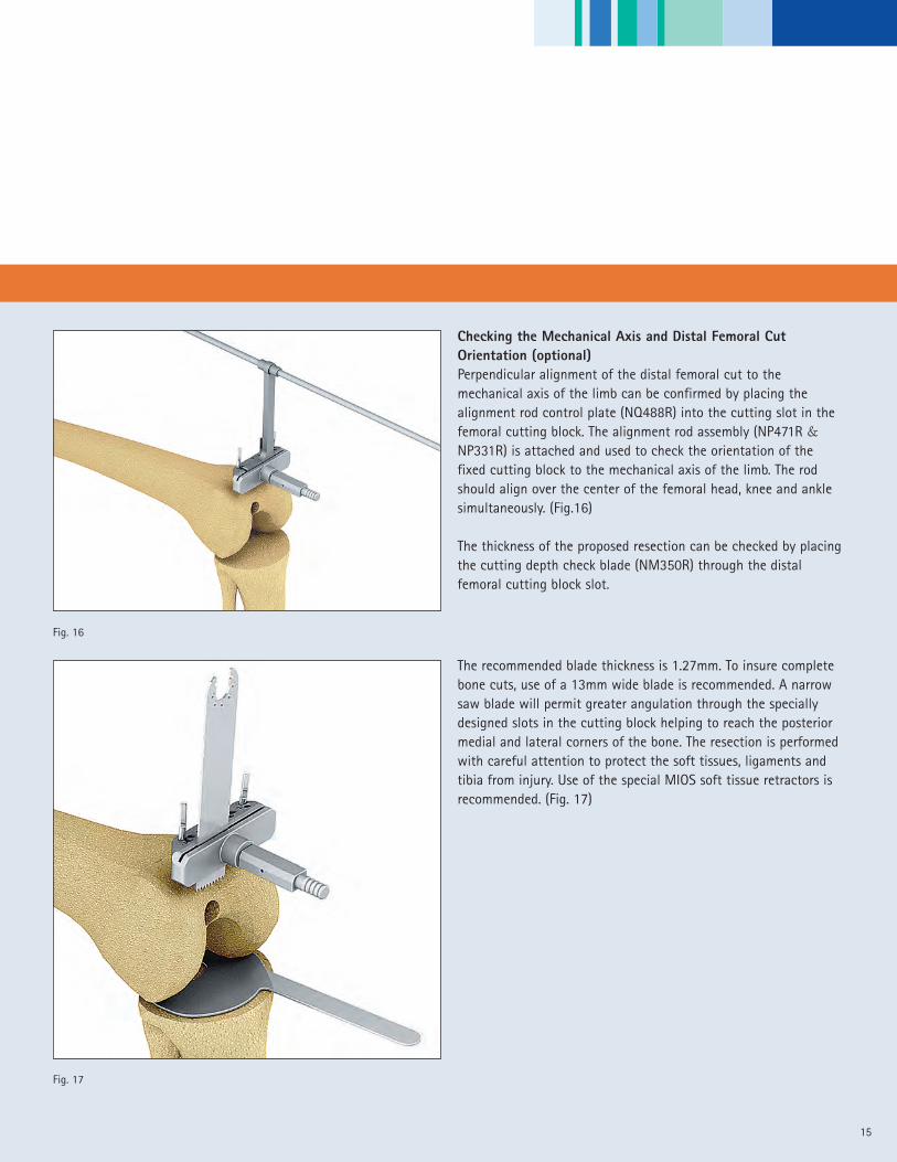
Checking the Mechanical Axis and Distal Femoral CutOrientation (optional)Perpendicular alignment of the distal femoral cut to themechanical axis of the limb can be confirmed by placing thealignment rod control plate (NQ488R) into the cutting slot in thefemoral cutting block. The alignment rod assembly (NP471R &NP331R) is attached and used to check the orientation of thefixed cutting block to the mechanical axis of the limb. The rodshould align over the center of the femoral head, knee and anklesimultaneously. (Fig.16)
The thickness of the proposed resection can be checked by placingthe cutting depth check blade (NM350R) through the distalfemoral cutting block slot.
The recommended blade thickness is 1.27mm. To insure completebone cuts, use of a 13mm wide blade is recommended. A narrowsaw blade will permit greater angulation through the speciallydesigned slots in the cutting block helping to reach the posteriormedial and lateral corners of the bone. The resection is performedwith careful attention to protect the soft tissues, ligaments andtibia from injury. Use of the special MIOS soft tissue retractors isrecommended. (Fig. 17)
Fig. 17
Fig. 16

Measured Resection Technique - Femur First
16
Fig. 19
Fig. 18
Fig. 21
Fig. 20
A
B
The femoral component size and the medial-lateral width of thedistal femur are measured using the femoral ruler NQ959R(Fig. 18). To further insure that the correct femur size is selected,it is helpful to template the femur prior to the procedure.
Anterior ReferencingThe femoral orientation guide (NQ476R) without the footplate ispre-assembled with the stylus from the NQ474R measuring guideand set so that the “SZ” indicator aligns to the femoral componentsize selected A . The guide is placed on the resected distal femurand centered in the medial-lateral direction. Rotation is set byplacing the guide parallel to Whiteside’s line. The anterior probe isset at the selected femoral component size and used to confirmthe anterior flange position of the femoral component. Carefulattention to avoid notching and medial-lateral overhang must beobserved. (Fig.19)
The holes for the orientation of the 4-in-1 cutting block are drilledusing two 3.2mm x 63mm threaded pins (NP583R) through theholes that correspond to the selected femoral component size(S, M, L)
Posterior ReferencingIn the posterior referencing technique, the size of the femur isestimated using pre-operative x-ray planning and confirmedintra-operatively using the femoral size gauge (NQ959R). Thefemoral measuring device “modular” (NQ954R) with the footplateis placed onto the distal femur with careful attention to insurethat the posterior footplate is in full contact with the posteriorcondyles.
The guide should be centered in the medial-lateral direction onthe distal femur. The holes for the orientation of the 4-in-1cutting block are drilled using the 3.2mm long threaded pin(NP583R) through the holes in the distal femoral orientation guidethat correspond to the selected femoral component size, (S, M, L).(Fig. 19) To further insure that the correct femoral component isselected, it is helpful to template the femoral component size priorto the procedure.
A

17
With the posterior foot plates positioned flush against theposterior condyles, the stylus is placed on the anterior cortex atthe location of the preferred exit point of the anterior bone cut (orwhere the anterior lateral aspect of the anterior flange of thefemoral component is ideally positioned). The femoral componentsize is read directly from the gauge at the “SZ” size location A .The femoral component size is also indicated on the gauge on thestylus B (Fig. 20 & 21)
Setting the Orientation of the Femoral Component (4-in-1cutting block orientation)The “Adjust Size” mechanism is locked using screw A so that thearrow N” aligns with the femoral component size selected in linewith the size indicator “SZ”. The stylus screw B is locked at theappropriate anterior lateral location (the point on the anteriorcortex at which the anterior flange of the femoral component willend) and the holes for the 4-in-1 cutting block are drilled throughthe two “parallel” drill hole positions for the appropriatecomponent size (S, M, L). In the example shown in Fig. 22, a size 5femoral component is indicated. In this case, the size “M” holesare drilled through the two parallel holes ( ). If 3 degrees ofexternal rotation is preferred, the holes are drilled through theappropriate “offset” holes ( ) for the right or left femur. In thisexample, the “offset” holes for a right femur are drilled. (Fig. 22)
Note: If a left femur is drilled, the opposite set of “offset” holes isselected.
If after setting the anterior probe, the SZ indicator falls betweensizes, the size is adjusted by moving the SZ component of thefemoral measuring device to the preferred size and locked usingscrew A . The appropriate size 4-in-1 cutting block (femoralcomponent size) holes are then drilled using the same techniqueas noted in the previous step. (Fig. 23)
Fig. 22
Fig. 23
Drill Holes Cutting block size
S 1, 2
M 3, 4, 5
L 6, 7
A
A
B
Measured Resection Technique - Femur First
18
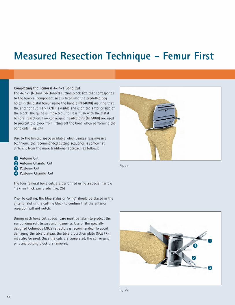
Completing the Femoral 4-in-1 Bone CutThe 4-in-1 (NQ441R-NQ446R) cutting block size that correspondsto the femoral component size is fixed into the predrilled pegholes in the distal femur using the handle (NQ460R) insuring thatthe anterior cut mark (ANT) is visible and is on the anterior side ofthe block. The guide is impacted until it is flush with the distalfemoral resection. Two converging headed pins (NP586R) are usedto prevent the block from lifting off the bone when performing thebone cuts. (Fig. 24)
Due to the limited space available when using a less invasivetechnique, the recommended cutting sequence is somewhatdifferent from the more traditional approach as follows:
1 Anterior Cut2 Anterior Chamfer Cut3 Posterior Cut4 Posterior Chamfer Cut
The four femoral bone cuts are performed using a special narrow1.27mm thick saw blade. (Fig. 25)
Prior to cutting, the tibia stylus or “wing” should be placed in theanterior slot in the cutting block to confirm that the anteriorresection will not notch.
During each bone cut, special care must be taken to protect thesurrounding soft tissues and ligaments. Use of the speciallydesigned Columbus MIOS retractors is recommended. To avoiddamaging the tibia plateau, the tibia protection plate (NQ377R)may also be used. Once the cuts are completed, the convergingpins and cutting block are removed.
Fig. 24
Fig. 25
1
3
4
2
19
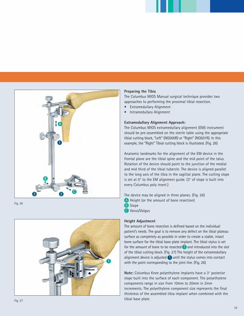
Preparing the TibiaThe Columbus MIOS Manual surgical technique provides twoapproaches to performing the proximal tibial resection.• Extramedullary Alignment• Intramedullary Alignment
Extramedullary Alignment Approach:The Columbus MIOS extramedullary alignment (EM) instrumentshould be pre-assembled on the sterile table using the appropriatetibial cutting block, “Left” (NQ500R) or “Right” (NQ501R). In thisexample, the “Right” Tibial cutting block is illustrated. (Fig. 26)
Anatomic landmarks for the alignment of the EM device in thefrontal plane are the tibial spine and the mid point of the talus.Rotation of the device should point to the junction of the medialand mid third of the tibial tubercle. The device is aligned parallelto the long axis of the tibia in the sagittal plane. The cutting slopeis set at 0° to the EM alignment guide. (3° of slope is built intoevery Columbus poly insert.)
The device may be aligned in three planes. (Fig. 26)A Height (or the amount of bone resection)B SlopeC Varus/Valgus
Height AdjustmentThe amount of bone resection is defined based on the individualpatient’s needs. The goal is to remove any defect on the tibial plateausurface as completely as possible in order to create a stable, intactbone surface for the tibial base plate implant. The tibial stylus is setfor the amount of bone to be resected T and introduced into the slotof the tibial cutting block. (Fig. 27) The height of the extramedullaryalignment device is adjusted 1 until the stylus comes into contactwith the point corresponding to the joint line. (Fig. 26)
Note: Columbus Knee polyethylene implants have a 3° posteriorslope built into the surface of each component. The polyethylenecomponents range in size from 10mm to 20mm in 2mmincrements. The polyethylene component size represents the finalthickness of the assembled tibia implant when combined with thetibial base plate.
Fig. 26
Fig. 27
C
1
23��
B
A��
��
T
Measured Resection Technique - Femur First
20
Slope AlignmentAlignment for slope in the sagittal plane is adjusted by unlockingscrew 2 and moving the construct along the length of themalleolar connecting rod (NQ494R). The distance between theetched lines on the ankle clamp connecting rod correspond to 1°of slope where the tibial length is 40cm and can be used as aguide for the average patient. (Fig. 26)
Varus/Valgus alignmentVarus/Valgus alignment is controlled by adjusting the connectingrod screw 3 of the ankle clamp. In the unlocked position, theconnecting rod can be moved medial or lateral thereby adjustingthe varus/valgus orientation of the tibial cutting block. Thedistance between the etched lines on the anterior surface of theankle clamp correspond to a 1° change in cases where the tibiallength is 40cm and can be used as a guide for the average patient.(Fig. 26)
21
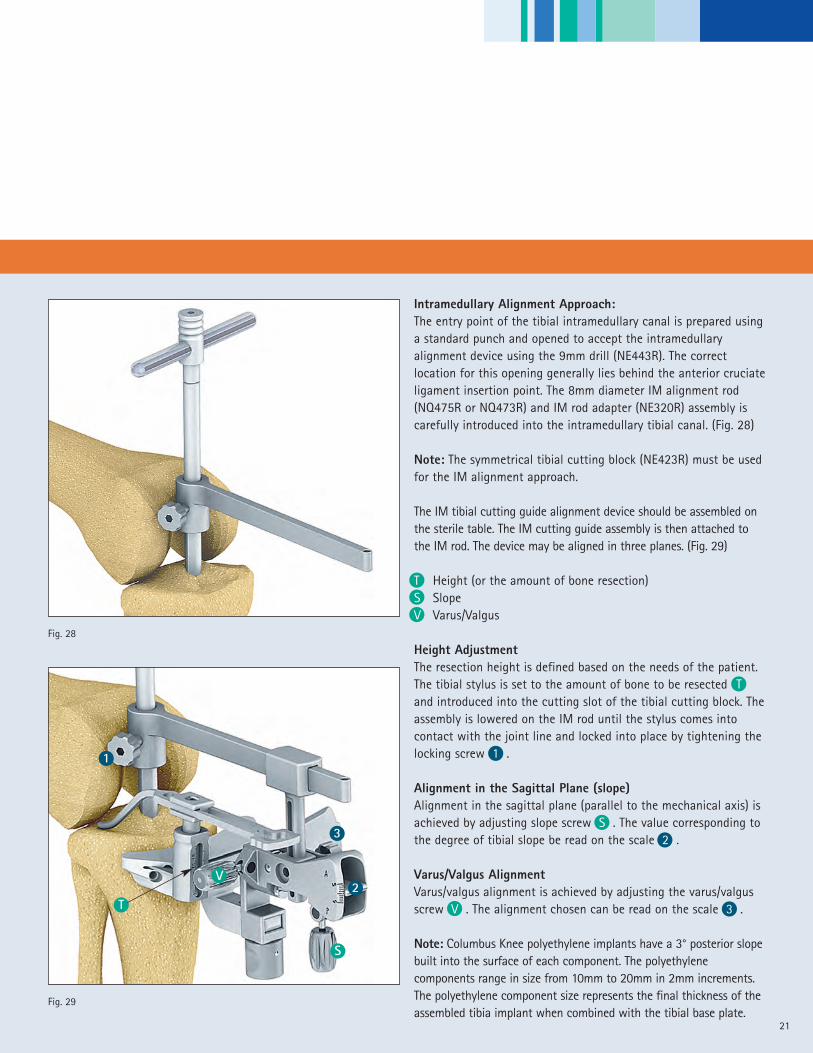
Intramedullary Alignment Approach:The entry point of the tibial intramedullary canal is prepared usinga standard punch and opened to accept the intramedullaryalignment device using the 9mm drill (NE443R). The correctlocation for this opening generally lies behind the anterior cruciateligament insertion point. The 8mm diameter IM alignment rod(NQ475R or NQ473R) and IM rod adapter (NE320R) assembly iscarefully introduced into the intramedullary tibial canal. (Fig. 28)
Note: The symmetrical tibial cutting block (NE423R) must be usedfor the IM alignment approach.
The IM tibial cutting guide alignment device should be assembled onthe sterile table. The IM cutting guide assembly is then attached tothe IM rod. The device may be aligned in three planes. (Fig. 29)
T Height (or the amount of bone resection)S SlopeV Varus/Valgus
Height AdjustmentThe resection height is defined based on the needs of the patient.The tibial stylus is set to the amount of bone to be resected Tand introduced into the cutting slot of the tibial cutting block. Theassembly is lowered on the IM rod until the stylus comes intocontact with the joint line and locked into place by tightening thelocking screw 1 .
Alignment in the Sagittal Plane (slope)Alignment in the sagittal plane (parallel to the mechanical axis) isachieved by adjusting slope screw S . The value corresponding tothe degree of tibial slope be read on the scale 2 .
Varus/Valgus AlignmentVarus/valgus alignment is achieved by adjusting the varus/valgusscrew V . The alignment chosen can be read on the scale 3 .
Note: Columbus Knee polyethylene implants have a 3° posterior slopebuilt into the surface of each component. The polyethylenecomponents range in size from 10mm to 20mm in 2mm increments.The polyethylene component size represents the final thickness of theassembled tibia implant when combined with the tibial base plate.
Fig. 28
T
V2
3
S
Fig. 29
1

Measured Resection Technique - Femur First
22
Resection of the Tibial PlateauThe tibial cutting block is fixed to the bone with three threadedheadless pins (NP583R). Two pins are placed through the holesmarked “0” and one pin is placed through the appropriate medialconverging hole. The extramedullary or intramedullary alignmentdevice is now removed and the proximal tibial bone resection isperformed using a 1.27mm thick saw blade. Careful attention notto damage the posterior cruciate and collateral ligaments shouldbe observed during the resection procedure. Should the surgeonchoose to resect additional bone from the proximal tibia, thecutting block may be moved on the existing parallel headless pinsin increments of 2mm for a total of 4mm. (Fig. 30)
Note: Because each Columbus Knee polyethylene insert has 3°ofslope built into the component surface, the recommendedproximal tibial resection is generally performed at 0° of slope. Thesurgeon may choose to introduce more or less slope depending onthe needs of the patient.
Sizing the Tibial Plateau ComponentThe trial tibial plateau (NQ381R – NQ389R) that best fits theresected tibial surface is selected. Five full sizes and four plussizes, which are 3-4 mm wider in the AP dimension, are available.
The trial polyethylene insert is placed on the trial base plate.
Rotational Alignment of the Tibial componentsRotational alignment of the tibial base plate can now beestablished by aligning the tibial base plate trial under the femoraltrial and “floating” the tibial component into position whileperforming a flexion/extension maneuver of the limb. This trialreduction maneuver is performed using a trial polyethylene insertthickness that provides accurate limb alignment and joint stabilityin flexion and extension. The Columbus Knee polyethylene insertscome in 6 sizes matching each tibial base plate andranging in sizes from 10 – 20 mm in 2mm increments.
Fig. 30
Fig. 31
23
Rotation of the trial tibial base plate can also be established byaligning the trial using anatomic landmarks. These include:
• A point on the anterior tibia at the junction of the medial andmid-third of the patella tendon
• A line connecting the insertion of the posterior cruciateligament and the middle of the patella tendon.
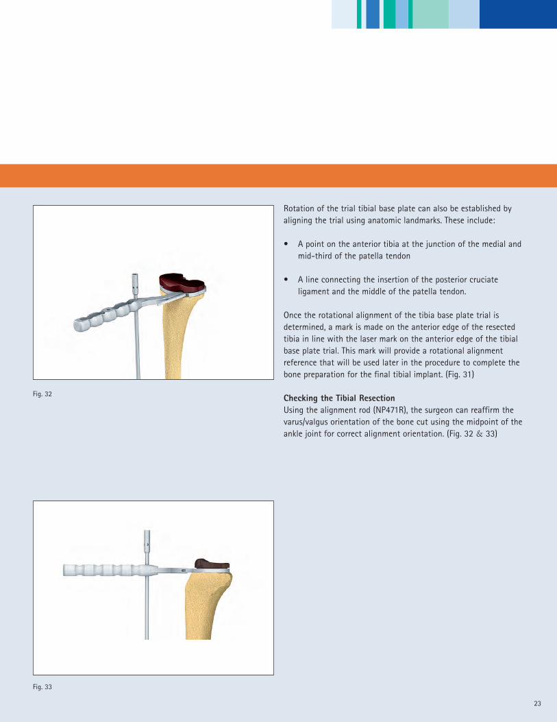
Once the rotational alignment of the tibia base plate trial isdetermined, a mark is made on the anterior edge of the resectedtibia in line with the laser mark on the anterior edge of the tibialbase plate trial. This mark will provide a rotational alignmentreference that will be used later in the procedure to complete thebone preparation for the final tibial implant. (Fig. 31)
Checking the Tibial ResectionUsing the alignment rod (NP471R), the surgeon can reaffirm thevarus/valgus orientation of the bone cut using the midpoint of theankle joint for correct alignment orientation. (Fig. 32 & 33)
Fig. 32
Fig. 33

Measured Resection Technique - Femur First
24
Preparation of the Tibial PlateauThe appropriate size trial tibial base plate is fixed onto theresected surface of the tibia using the previous rotationalalignment mark for alignment. Each Columbus Knee tibial baseplate trial (and final implant component) features a rotationalalignment mark on the anterior edge. The plateau is fixed to theresected surface using two short headed pins (NP585R). Theappropriate tibia drill sleeve is introduced onto the trial base plateand the bone is drilled with the correct drill size to accept thebase plate stem. A special handle is provided to stabilize the drillsleeve when drilling. (Fig. 34)
• Tibial plateau sizes T1 – T3/T3+ – use the 12mm diameter drill(NQ366R)
• Tibial plateau sizes T4/T4+ -T5 – use the 14mm diameter drill(NQ376R)
The winglet chisel/keel trial (NQ391R – NQ395R) and handle(NQ565R) assembly is impacted to the stop position through thewinglet chisel/keel trial guide (NQ396R). (Fig. 35)
The winglet chisel/keel trial is disengaged from its handle and leftin place in the base plate to perform a trial reduction.
Fig. 34
Fig. 35
25
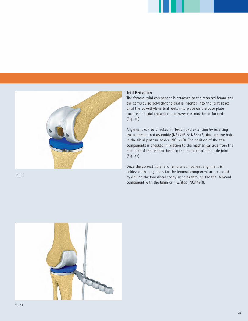
Trial ReductionThe femoral trial component is attached to the resected femur andthe correct size polyethylene trial is inserted into the joint spaceuntil the polyethylene trial locks into place on the base platesurface. The trial reduction maneuver can now be performed.(Fig. 36)
Alignment can be checked in flexion and extension by insertingthe alignment rod assembly (NP471R & NE331R) through the holein the tibial plateau holder (NQ378R). The position of the trialcomponents is checked in relation to the mechanical axis from themidpoint of the femoral head to the midpoint of the ankle joint.(Fig. 37)
Once the correct tibial and femoral component alignment isachieved, the peg holes for the femoral component are preparedby drilling the two distal condylar holes through the trial femoralcomponent with the 6mm drill w/stop (NQ449R).
Fig. 36
Fig. 37
Measured Resection Technique - Femur First
26
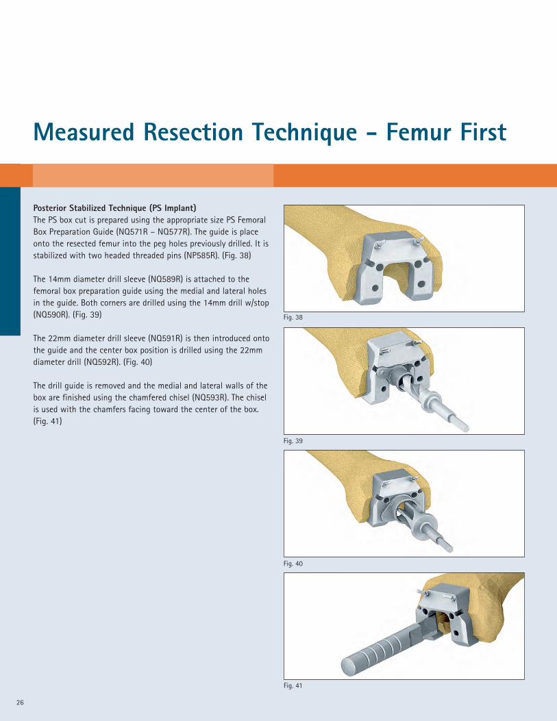
Posterior Stabilized Technique (PS Implant)The PS box cut is prepared using the appropriate size PS FemoralBox Preparation Guide (NQ571R – NQ577R). The guide is placeonto the resected femur into the peg holes previously drilled. It isstabilized with two headed threaded pins (NP585R). (Fig. 38)
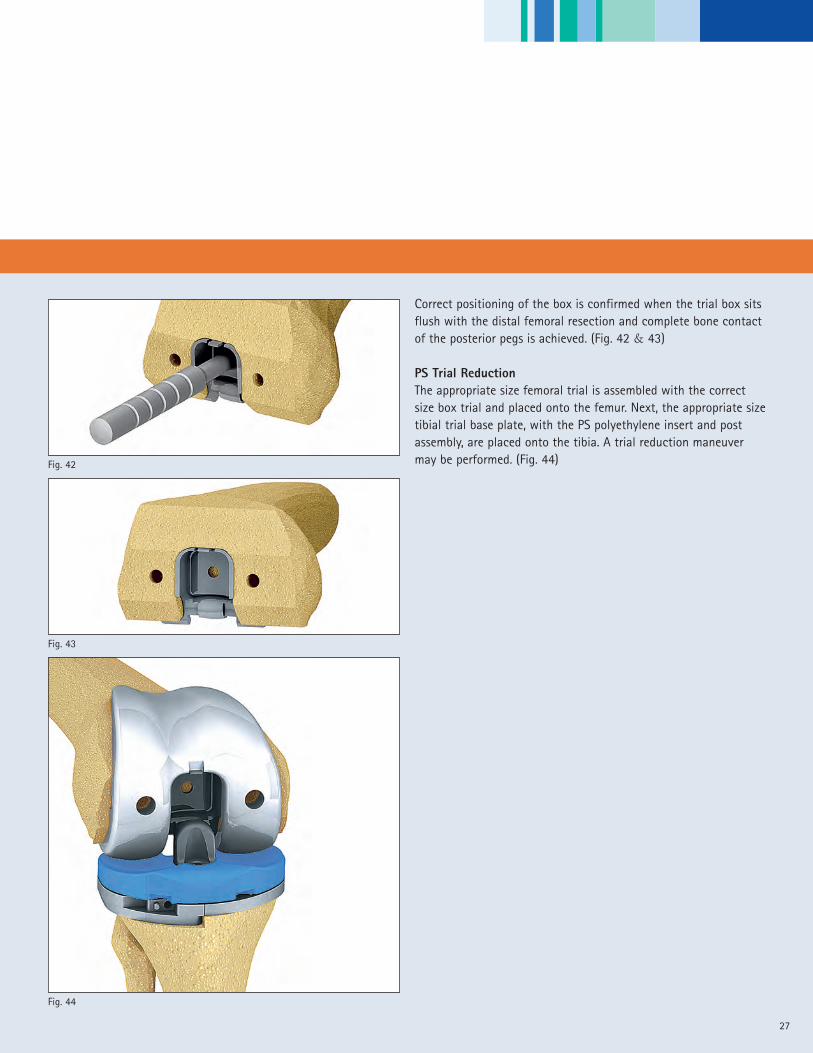
The 14mm diameter drill sleeve (NQ589R) is attached to thefemoral box preparation guide using the medial and lateral holesin the guide. Both corners are drilled using the 14mm drill w/stop(NQ590R). (Fig. 39)
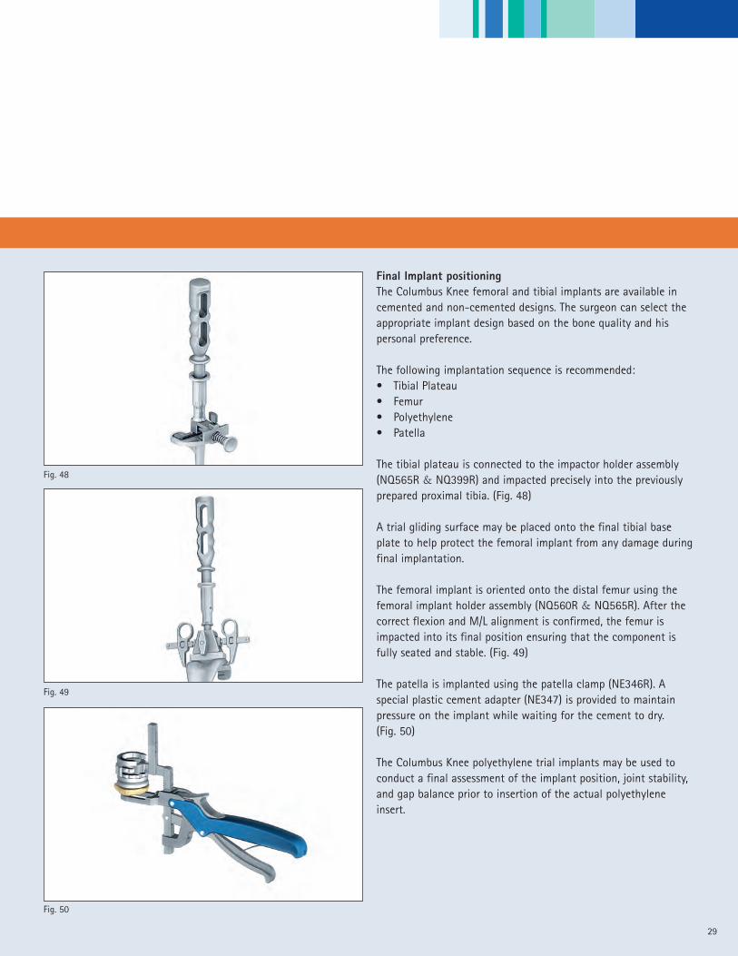
The 22mm diameter drill sleeve (NQ591R) is then introduced ontothe guide and the center box position is drilled using the 22mmdiameter drill (NQ592R). (Fig. 40)
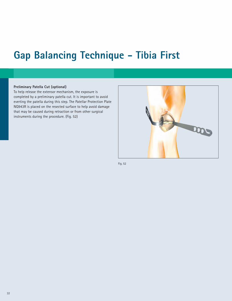
The drill guide is removed and the medial and lateral walls of thebox are finished using the chamfered chisel (NQ593R). The chiselis used with the chamfers facing toward the center of the box.(Fig. 41)
Fig. 39
Fig. 38
Fig. 41
Fig. 40
27
Correct positioning of the box is confirmed when the trial box sitsflush with the distal femoral resection and complete bone contactof the posterior pegs is achieved. (Fig. 42 & 43)
PS Trial ReductionThe appropriate size femoral trial is assembled with the correctsize box trial and placed onto the femur. Next, the appropriate sizetibial trial base plate, with the PS polyethylene insert and postassembly, are placed onto the tibia. A trial reduction maneuvermay be performed. (Fig. 44)
Fig. 44
Fig. 43
Fig. 42

Measured Resection Technique - Femur First
Preparation of the PatellaThe patella clamp is attached to the patella and the clamp istightened until it is securely locked on the anterior and posteriorsurfaces of the bone. (Fig. 45)
The thickness of the patella may be measured A using the patellaclamp (NE346R). The clamp is set to the chosen resection height B and the resection is performed with the oscillating saw
through the cutting slot in the halo portion of the device. (Fig. 46)
The measured thickness should not be exceeded after implantationof the patella implant.
The cutting guide halo is removed and the drill guide (NQ478R) isfixed onto the clamp. The patella peg holes are drilled with the6mm drill w/stop (NQ449R). (Fig. 47)
The size of the patella is determined using one of the four trialpatella implants. For patella size options see the overview onpage 37.
Note: The Columbus Knee patella component includes threesymmetric fixation pegs and, therefore, can be placed in anyrotational position.
28
A
Fig. 47
Fig. 46
Fig. 45
B
Final Implant positioningThe Columbus Knee femoral and tibial implants are available incemented and non-cemented designs. The surgeon can select theappropriate implant design based on the bone quality and hispersonal preference.
The following implantation sequence is recommended:• Tibial Plateau• Femur• Polyethylene• Patella
The tibial plateau is connected to the impactor holder assembly(NQ565R & NQ399R) and impacted precisely into the previouslyprepared proximal tibia. (Fig. 48)
A trial gliding surface may be placed onto the final tibial baseplate to help protect the femoral implant from any damage duringfinal implantation.
The femoral implant is oriented onto the distal femur using thefemoral implant holder assembly (NQ560R & NQ565R). After thecorrect flexion and M/L alignment is confirmed, the femur isimpacted into its final position ensuring that the component isfully seated and stable. (Fig. 49)
The patella is implanted using the patella clamp (NE346R). Aspecial plastic cement adapter (NE347) is provided to maintainpressure on the implant while waiting for the cement to dry.(Fig. 50)
The Columbus Knee polyethylene trial implants may be used toconduct a final assessment of the implant position, joint stability,and gap balance prior to insertion of the actual polyethyleneinsert.
29
Fig. 50
Fig. 49
Fig. 48

Measured Resection Technique - Femur First
30
ClosureThe wound is closed using standard closure techniques. (Fig. 51)
Fig. 51

31
32
Gap Balancing Technique - Tibia First
Preliminary Patella Cut (optional)To help release the extensor mechanism, the exposure iscompleted by a preliminary patella cut. It is important to avoideverting the patella during this step. The Patellar Protection PlateNQ943R is placed on the resected surface to help avoid damagethat may be caused during retraction or from other surgicalinstruments during the procedure. (Fig. 52)
Fig. 52

33
Preparing the TibiaThe Columbus MIOS manual surgical technique provides twoapproaches to performing the proximal tibial resection.• Extramedullary Alignment• Intramedullary Alignment
Extramedullary Alignment Approach:The extramedullary alignment (EM) instrument should bepre-assembled on the sterile table by the scrub nurse using theappropriate tibial cutting block, “Left” (NQ500R) or “Right” (NQ501R).In this example, the “Right” Tibial cutting block is illustrated. (Fig. 53)
Anatomic landmarks for the alignment of the EM device in thefrontal plane are the tibial spine and the mid point of the talus.Rotation of the device should point to the junction of the medialand mid third of the tibial tubercle. The device is aligned parallelto the long axis of the tibia in the sagittal plane. The cutting slopeis set at 0° to the EM alignment guide. (3° of slope is built intoevery Columbus poly insert.)
The device is aligned in three planes. (Fig. 54)A Height (or the amount of bone resection)B SlopeC Varus/Valgus
Height AdjustmentThe amount of bone resection is defined based on the individualpatient’s needs. The goal is to remove any defect on the tibialplateau surface as completely as possible in order to create a stable,intact bone surface for the tibial base plate implant. The tibialstylus is set for the amount of bone to be resected below thestylus T and introduced into the slot of the tibial cutting block.(Fig. 54) The height of the extramedullary alignment device isadjusted 1 until the stylus comes into contact with the pointcorresponding to the joint line. (Fig. 53 & 54)
Note: Columbus Knee polyethylene implants have a 3° posteriorslope built into the surface of each component. The polyethylenecomponents range in size from 10mm to 20mm in 2mmincrements. The polyethylene component size represents the finalthickness of the assembled tibia implant when combined with thetibial base plate.
Fig. 53
Fig. 54
C
1
��
B
A��
��
T
Gap Balancing Technique - Tibia First
34
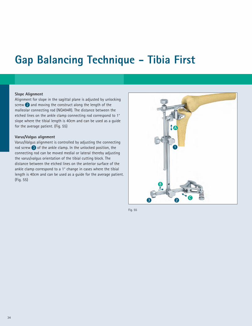
Slope AlignmentAlignment for slope in the sagittal plane is adjusted by unlockingscrew 2 and moving the construct along the length of themalleolar connecting rod (NQ494R). The distance between theetched lines on the ankle clamp connecting rod correspond to 1°slope where the tibial length is 40cm and can be used as a guidefor the average patient. (Fig. 55)
Varus/Valgus alignmentVarus/Valgus alignment is controlled by adjusting the connectingrod screw 3 of the ankle clamp. In the unlocked position, theconnecting rod can be moved medial or lateral thereby adjustingthe varus/valgus orientation of the tibial cutting block. Thedistance between the etched lines on the anterior surface of theankle clamp correspond to a 1° change in cases where the tibiallength is 40cm and can be used as a guide for the average patient.(Fig. 55)
Fig. 55
C
1
23��
B
A��
��
35
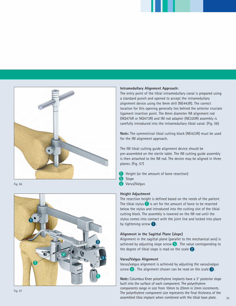
Intramedullary Alignment Approach:The entry point of the tibial intramedullary canal is prepared usinga standard punch and opened to accept the intramedullaryalignment device using the 9mm drill (NE443R). The correctlocation for this opening generally lies behind the anterior cruciateligament insertion point. The 8mm diameter IM alignment rod(NQ475R or NQ473R) and IM rod adapter (NE320R) assembly iscarefully introduced into the intramedullary tibial canal. (Fig. 56)
Note: The symmetrical tibial cutting block (NE423R) must be usedfor the IM alignment approach.
The IM tibial cutting guide alignment device should bepre-assembled on the sterile table. The IM cutting guide assemblyis then attached to the IM rod. The device may be aligned in threeplanes. (Fig. 57)
T Height (or the amount of bone resection)S SlopeV Varus/Valgus
Height AdjustmentThe resection height is defined based on the needs of the patient.The tibial stylus T is set for the amount of bone to be resectedbelow the stylus and introduced into the cutting slot of the tibialcutting block. The assembly is lowered on the IM rod until thestylus comes into contact with the joint line and locked into placeby tightening screw 1 .
Alignment in the Sagittal Plane (slope)Alignment in the sagittal plane (parallel to the mechanical axis) isachieved by adjusting slope screw S . The value corresponding tothe degree of tibial slope is read on the scale 2 .
Varus/Valgus AlignmentVarus/valgus alignment is achieved by adjusting the varus/valgusscrew V . The alignment chosen can be read on the scale 3 .
Note: Columbus Knee polyethylene implants have a 3° posterior slopebuilt into the surface of each component. The polyethylenecomponents range in size from 10mm to 20mm in 2mm increments.The polyethylene component size represents the final thickness of theassembled tibia implant when combined with the tibial base plate.
Fig. 56
T
V2
3
S
Fig. 57
1

Gap Balancing Technique - Tibia First
36
Tibial ResectionThe tibial cutting block is fixed to the bone with three threadedheadless pins (NP583R). Two pins are placed through the holesmarked “0” and one pin is placed through the appropriate medialconverging hole. The extramedullary or intramedullary alignmentdevice is now removed and the proximal tibial bone resection isperformed using a 1.27mm thick saw blade. Careful attention notto damage the ligaments should be observed during the resectionprocedure. Should the surgeon choose to resect additional bonefrom the proximal tibia, the cutting block may be moved on theexisting parallel headless pins in increments of 2mm for a total of4mm. (Fig. 58)
Note: Should the surgeon choose to reduce the amount of resectionprior to performing the bone cut, the tibia cutting block pinfixation holes allow for an additional 2mm of superior positioning.
Note: Because each Columbus Knee polyethylene insert has 3°ofslope built into the component surface, the recommendedproximal tibial resection is generally performed at 0° of slope. Thesurgeon may choose to introduce more or less slope depending onthe needs of the patient.
Fig. 58

37
Gap BalancingGap balancing is a 2 step process. In step 1, the flexion andextension gaps are measured and recorded. During step 1, it maybe necessary to perform a ligamentous release to bring the gapsclose to each other. In step 2, the average extension gap will beadjusted to equal the average flexion gap.
Step 1: Measure the Flexion and Extension GapsThe goal in this step is to measure the average extension andflexion gaps. If there is significant discrepancy (greater than 3mm)between medial and lateral measurements in extension; or medialand lateral in flexion, a release may be performed. Then remeasurethe collaterals in both extension and flexion. If you plan to resectthe PCL, it should be resected prior to these measurements.
The extension gap is measured with the distractor, and the medialand lateral gaps are AVERAGED to obtain a measurement of theaverage extension gap. For instance, if the medial extension gap is8mm, and the lateral extension gap is 12 mm, than the averageextension gap “EG”, is 10mm. This measurement is taken with theknee in 0° of extension. If there is a large discrepancy (greaterthan 3mm), a standard collateral and soft tissue release must beperformed, and new measurements obtained. (Fig. 59)
A similar measurement is taken to establish the average flexiongap “FG” at 90° of flexion. As an example, if the medial flexiongap is 13 mm and the lateral flexion gap is 15 mm, the averageflexion gap is 14mm. If there is a large discrepancy betweenmedial and lateral gaps, this may require a release. Smalldifferences (less than 3 mm) can be corrected with rotation of thefemoral component. (Fig. 60)
Fig. 59
Fig. 60
Gap Balancing Technique - Tibia First
38
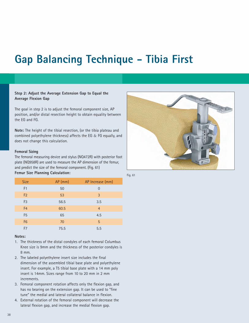
Step 2: Adjust the Average Extension Gap to Equal theAverage Flexion Gap
The goal in step 2 is to adjust the femoral component size, APposition, and/or distal resection height to obtain equality betweenthe EG and FG.
Note: The height of the tibial resection, (or the tibia plateau andcombined polyethylene thickness) affects the EG & FG equally, anddoes not change this calculation.
Femoral SizingThe femoral measuring device and stylus (NQ472R) with posterior footplate (NQ958R) are used to measure the AP dimension of the femur,and predict the size of the femoral component. (Fig. 61)Femur Size Planning Calculation:
Notes:1. The thickness of the distal condyles of each femoral Columbus
Knee size is 9mm and the thickness of the posterior condyles is8 mm.
2. The labeled polyethylene insert size includes the finaldimension of the assembled tibial base plate and polyethyleneinsert. For example, a T5 tibial base plate with a 14 mm polyinsert is 14mm. Sizes range from 10 to 20 mm in 2 mmincrements.
3. Femoral component rotation affects only the flexion gap, andhas no bearing on the extension gap. It can be used to “finetune” the medial and lateral collateral balance in flexion.
4. External rotation of the femoral component will decrease thelateral flexion gap, and increase the medial flexion gap.
Size AP (mm) AP Increase (mm)
F1 50 0
F2 53 3
F3 56.5 3.5
F4 60.5 4
F5 65 4.5
F6 70 5
F7 75.5 5.5
Fig. 61

39
Gap Balancing Examples:The following gap balancing scenarios are provided as examples ofthe 2-step gap balancing technique. These simplistic examples areprovided to illustrate the concept of Gap Balancing and are notintended to provide complete details or methods. There are manyaccepted techniques to manage ligament balancing not presentedhere. The surgeon must have a complete understanding of all theprinciples and techniques for soft tissue balancing to fully utilizethis approach. At the end of this step the amount of distalresection will be established. The standard resection is 9mm.
Example 1:The average EG measures 11 and the average FG measures 16. Thefemur measures a size 4, using the femoral measuring device(NQ959R) or pre-op template. There are two solutions to balancethis scenario.
Solution #1: Increase the femoral component size from size 4 tosize 5; this will decrease the FG 4.5 mm. A 10 mm poly insert willreduce the EG to 1mm and the FG to 1.5mm. The distal femoralresection is 9mm.
Solution #2: Increase the amount of distal femur resected fromthe standard 9mm to 13mm, (increased 4 mm). The distal femoralresection is 13mm. This will increase the EG only. The EG is now15mm and the FG is still 16mm. Increase the poly insert from 10 to 14mm. This leaves 1 mm of “free space” in extension and 2 mm in flexion.
Example 2:The average EG is 16mm and the average FG is 12mm. The femurmeasures a size 4 (using the femoral measuring device or pre-optemplate); use the following options to balance this scenario.
Solution #1: Decrease the femoral component size from a size 4to a size 3. This will increase the FG 4mm and now the average EG& FG is 16mm. Increase the poly insert from 10 to 14 mm. Thisleaves 2 mm of ‘free space’ in extension and flexion. The distalfemoral resection is 9mm.
Solution #2: Release the PCL and remeasure the average extensiongap and average flexion gap. This will increase the flexion gap(typically 4mm). The distal femoral resection is 9mm.

Gap Balancing Technique - Tibia First
40
Solution #3: Resect 7mm of distal femur and install a 12mm(2mm less than standard) insert. This will leave 2mm “free space”in extension and 0mm “free space” in flexion. The distal femoralresection is 7mm.
Example 3:The average EG is 14mm and the average FG is 14mm. The femurmeasures a size 4, (using the femoral measuring device or pre-optemplate).
Solution: Install a 12 mm polyethylene insert. This leaves 2 mm of‘free space’ in extension and flexion. The distal femoral resectionis 9mm.
Example 4: The average EG is 7mm and the average FG is 7mm.The femur measures a size 4, (using the femoral measuring deviceor pre-op template).
Solution: Resect an additional 4 mm of proximal tibia and select a10 mm poly insert. This leaves 1 mm of “free space” in extensionand flexion. The distal femoral resection is 9mm.
Notes:1. When choosing the size of the femoral component, the
femoral measuring device can be held against the distal femurin line with the transepicondylar line to predict themedial/lateral size of the implant.
2. Translating the femoral component posteriorly will decrease(tighten) the flexion gap. When translating the femoralcomponent posteriorly to adjust the flexion gap, the femoralcomponent must not be moved to far posteriorly, or anteriornotching may occur.
3. The examples provided predict a final “free space” (remaininggap after implantation). Some surgeons may prefer 0, 1, or2 mm in extension, and slightly larger in flexion. It is left tothe surgeon’s judgment as to the correct amount of “freespace” necessary to create an ideal “balance” based on thepatient’s individual needs.
41
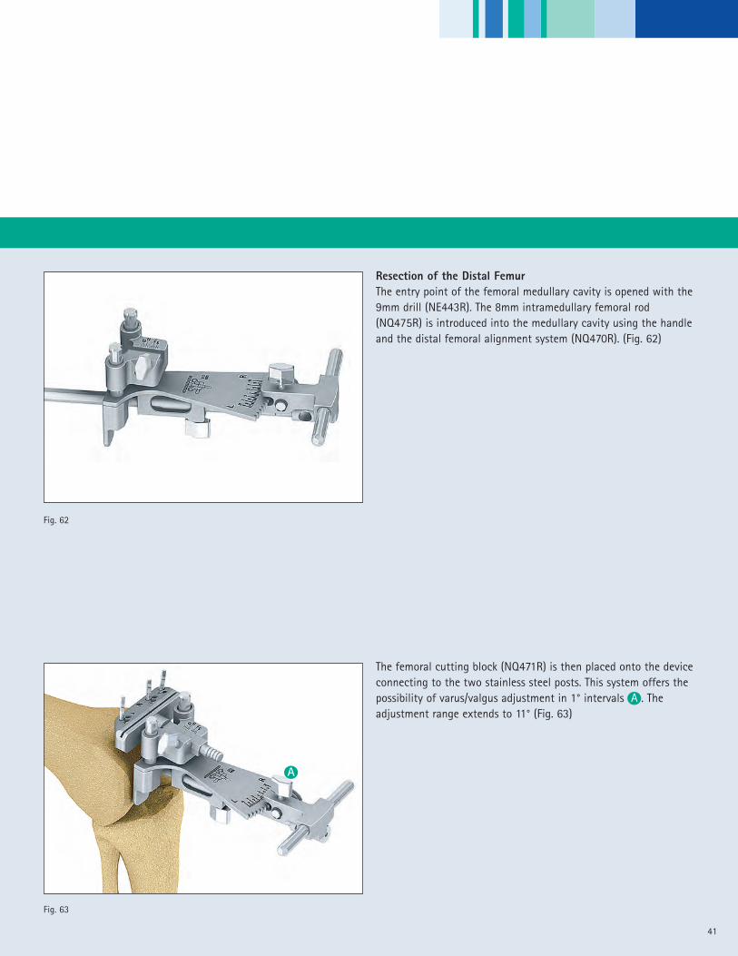
Resection of the Distal FemurThe entry point of the femoral medullary cavity is opened with the9mm drill (NE443R). The 8mm intramedullary femoral rod(NQ475R) is introduced into the medullary cavity using the handleand the distal femoral alignment system (NQ470R). (Fig. 62)
The femoral cutting block (NQ471R) is then placed onto the deviceconnecting to the two stainless steel posts. This system offers thepossibility of varus/valgus adjustment in 1° intervals A . Theadjustment range extends to 11° (Fig. 63)
Fig. 62
Fig. 63
A

Gap Balancing Technique - Tibia First
42
The distal resection is set by adjusting the cutting block holder tothe required resection thickness B . The typical distal resectionthickness is 9mm which is equal to the thickness of the distalfemoral condyles of the Columbus Knee femoral component. Thesurgeon may choose to modify the distal resection thickness basedon the value obtained from the gap balancing steps. Thevarus/valgus orientation A is adjusted off the anatomical axis ofthe femur.
The distal cutting block is fixed to the femur using two headlesspins through the holes marked “0”. One additional converging pinis introduced to stabilize the block and prevent it from lifting offthe bone during the bone resection. (Fig. 64).
The distal femoral cutting guide assembly is removed leaving thefemoral cutting block in place. (Fig. 65)
Note: The Columbus Knee distal femoral implant thickness is 9mm
Fig. 64
Fig. 65
A
B

43
Fig. 67
Fig. 66
Checking the Mechanical Axis and Distal Femoral CutOrientation (optional)Perpendicular alignment of the distal femoral cut to themechanical axis of the limb can be confirmed by placing thealignment rod control plate (NQ488R) into the cutting slot in thefemoral cutting block. The alignment rod assembly (NP471R &NP331R) is attached and used to check the orientation of thefixed cutting block to the mechanical axis of the limb. The rodshould pass over the center of the femoral head, knee and anklesimultaneously. (Fig.66)
The thickness of the proposed resection can be checked by placingthe cutting depth check blade (NM350R) through the distalfemoral cutting block slot.
The recommended blade thickness is 1.27mm. To insure completebone cuts, use of a narrow saw blade is recommended. A narrowsaw blade will permit greater angulation through the speciallydesigned slots in the cutting block helping to reach the posteriormedial and lateral corners of the bone. The resection is performedwith careful attention to protect the soft tissues, ligaments andtibia from injury. Use of the special MIOS soft tissue retractors isrecommended. (Fig. 67)
Gap Balancing Technique - Tibia First
44
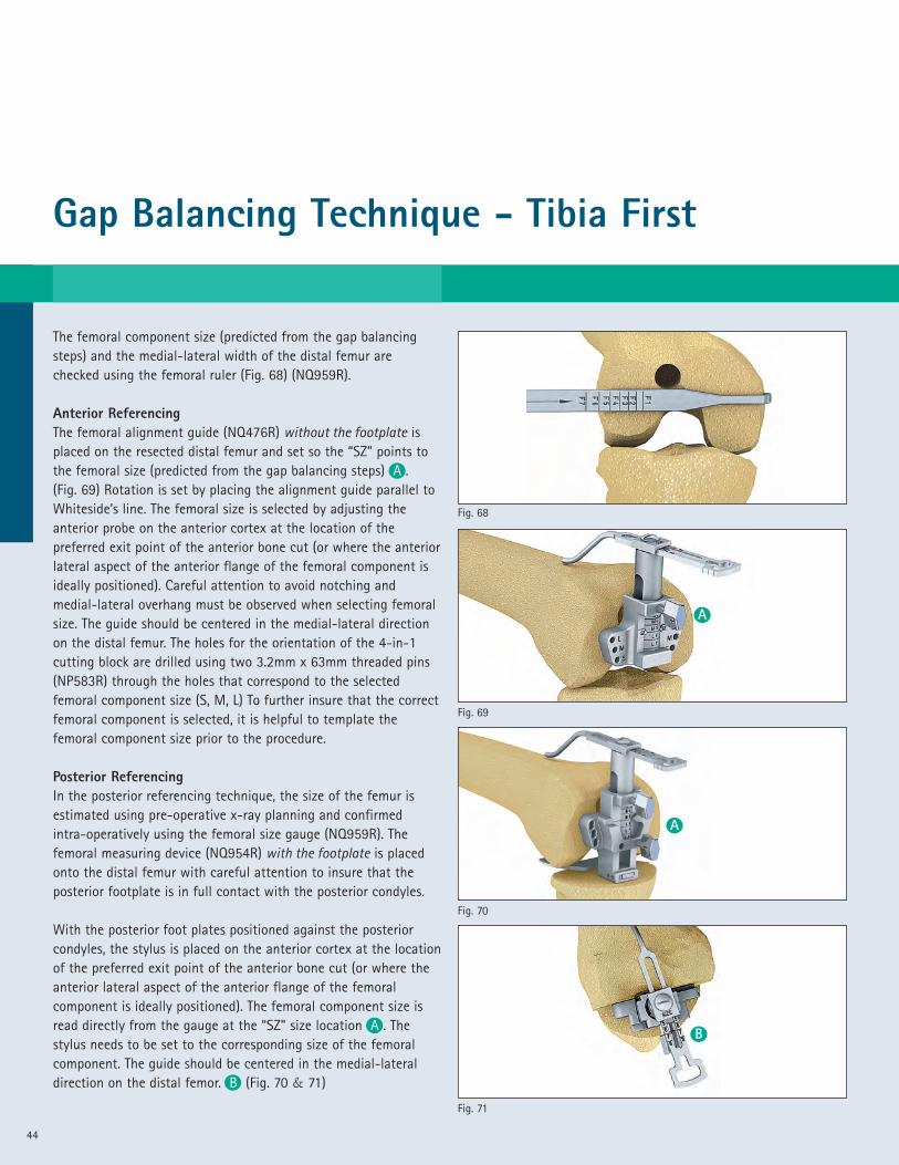
The femoral component size (predicted from the gap balancingsteps) and the medial-lateral width of the distal femur arechecked using the femoral ruler (Fig. 68) (NQ959R).
Anterior ReferencingThe femoral alignment guide (NQ476R) without the footplate isplaced on the resected distal femur and set so the “SZ” points tothe femoral size (predicted from the gap balancing steps) A .(Fig. 69) Rotation is set by placing the alignment guide parallel toWhiteside’s line. The femoral size is selected by adjusting theanterior probe on the anterior cortex at the location of thepreferred exit point of the anterior bone cut (or where the anteriorlateral aspect of the anterior flange of the femoral component isideally positioned). Careful attention to avoid notching andmedial-lateral overhang must be observed when selecting femoralsize. The guide should be centered in the medial-lateral directionon the distal femur. The holes for the orientation of the 4-in-1cutting block are drilled using two 3.2mm x 63mm threaded pins(NP583R) through the holes that correspond to the selectedfemoral component size (S, M, L) To further insure that the correctfemoral component is selected, it is helpful to template thefemoral component size prior to the procedure.
Posterior ReferencingIn the posterior referencing technique, the size of the femur isestimated using pre-operative x-ray planning and confirmedintra-operatively using the femoral size gauge (NQ959R). Thefemoral measuring device (NQ954R) with the footplate is placedonto the distal femur with careful attention to insure that theposterior footplate is in full contact with the posterior condyles.
With the posterior foot plates positioned against the posteriorcondyles, the stylus is placed on the anterior cortex at the locationof the preferred exit point of the anterior bone cut (or where theanterior lateral aspect of the anterior flange of the femoralcomponent is ideally positioned). The femoral component size isread directly from the gauge at the “SZ” size location A . Thestylus needs to be set to the corresponding size of the femoralcomponent. The guide should be centered in the medial-lateraldirection on the distal femor. B (Fig. 70 & 71)
Fig. 69
Fig. 68
Fig. 71
Fig. 70
A
B
A

45
Fig. 72
Fig. 73
A
A
B
B
Setting the Orientation of the Femoral Component (4-in-1cutting block orientation)The “Adjust Size” mechanism is locked using screw A so that thearrow “N” aligns with the femoral component size selected in linewith the size indicator “SZ”. The stylus screw B is locked at theappropriate anterior lateral location (the point on the anteriorcortex at which the anterior flange of the femoral component willend) and the holes for the 4-in-1 cutting block are drilled throughthe two “parallel” drill hole positions for the appropriatecomponent size (S, M, L). In the example shown in Fig. 72, a size 5femoral component is indicated. In this case, the size “M” holesare drilled through the two parallel holes ( ). If 3 degrees ofexternal rotation is preferred, the holes are drilled through theappropriate “offset” holes ( ) for the right or left femur. In thisexample, the “offset” holes for a right femur are drilled. (Fig. 72)
Note: If a left femur is drilled, the opposite set of “offset” holesare selected.
If after setting the anterior probe, the SZ indicator falls betweensizes, the size is adjusted by moving the “adjust size” block of thefemoral measuring device to the preferred size and locked usingscrew A . This allows the surgeon when between sizes, to moveeither up or down to the appropriate size. The appropriate size4-in-1 cutting block (femoral component size) holes are thendrilled using the same technique as noted in the previous step.(Fig. 73)
Drill Holes Cutting block size
S 1, 2
M 3, 4, 5
L 6, 7
Gap Balancing Technique - Tibia First
46
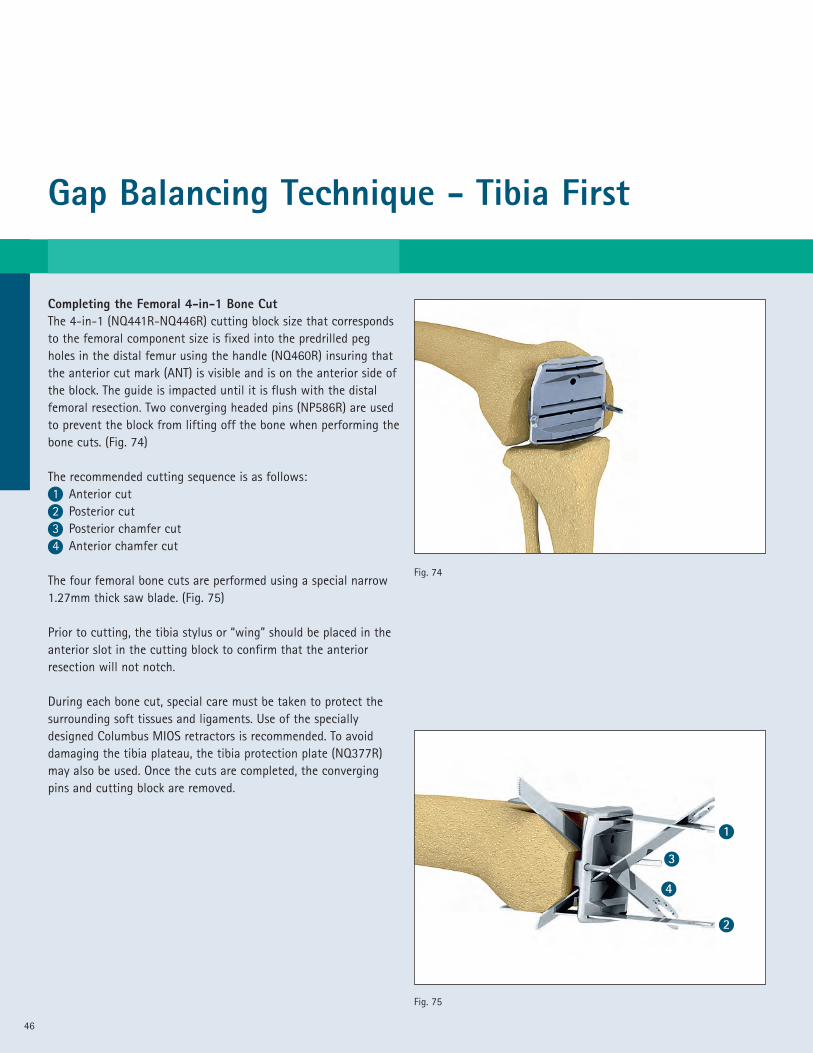
Completing the Femoral 4-in-1 Bone CutThe 4-in-1 (NQ441R-NQ446R) cutting block size that correspondsto the femoral component size is fixed into the predrilled pegholes in the distal femur using the handle (NQ460R) insuring thatthe anterior cut mark (ANT) is visible and is on the anterior side ofthe block. The guide is impacted until it is flush with the distalfemoral resection. Two converging headed pins (NP586R) are usedto prevent the block from lifting off the bone when performing thebone cuts. (Fig. 74)
The recommended cutting sequence is as follows:1 Anterior cut2 Posterior cut3 Posterior chamfer cut4 Anterior chamfer cut
The four femoral bone cuts are performed using a special narrow1.27mm thick saw blade. (Fig. 75)
Prior to cutting, the tibia stylus or “wing” should be placed in theanterior slot in the cutting block to confirm that the anteriorresection will not notch.
During each bone cut, special care must be taken to protect thesurrounding soft tissues and ligaments. Use of the speciallydesigned Columbus MIOS retractors is recommended. To avoiddamaging the tibia plateau, the tibia protection plate (NQ377R)may also be used. Once the cuts are completed, the convergingpins and cutting block are removed.
Fig. 74
Fig. 75
1
2
3
4

47
Fig. 76
Sizing the Tibial Base Plate ComponentThe trial tibial base plate (NQ381R – NQ389R) that best matchedthe resected tibial surface is selected. Five full sizes and four plussizes, which are 3-4 mm wider in the AP dimension, are available.
The trial polyethylene insert is placed on the trial base plate.
Rotational Alignment of the Tibial ComponentsAfter placement of the trial femoral base plate on the femur,rotational alignment of the tibial base plate can now beestablished by “floating” the tibial component into position whileperforming a flexion/extension maneuver of the limb. This trialreduction maneuver is performed using a trial polyethylene insertthickness that provides accurate limb alignment and joint stabilityin flexion and extension. The Columbus Knee polyethylene insertscome in 6 sizes matching each tibial base plate and ranging insizes from 10 – 20 mm in 2mm increments.
Rotation of the trial tibial base plate can also be established byaligning the trial using anatomic landmarks. These include:
• A point on the anterior tibia at the junction of the medial andmid-third of the tibial tubercle
• A line connecting the insertion of the posterior cruciateligament and the middle of the patella tendon.
Once the rotational alignment of the tibia base plate trial isdetermined, a mark is made on the anterior edge of the resectedtibia in line with the laser mark on the anterior edge of the tibialbase plate trial. This mark will provide a rotational alignmentreference that will be used later in the procedure to complete thebone preparation for the final tibial implant. (Fig. 76)
Gap Balancing Technique - Tibia First
48
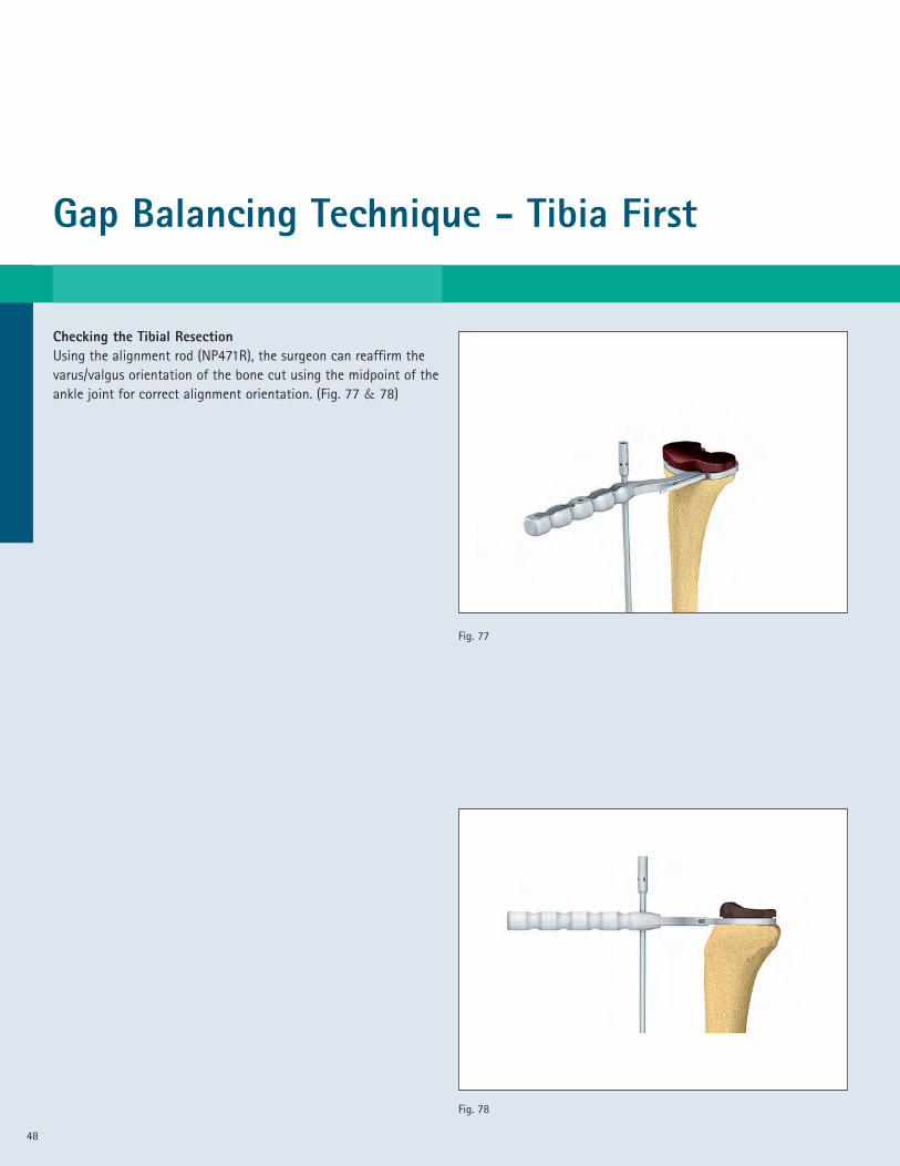
Checking the Tibial ResectionUsing the alignment rod (NP471R), the surgeon can reaffirm thevarus/valgus orientation of the bone cut using the midpoint of theankle joint for correct alignment orientation. (Fig. 77 & 78)
Fig. 77
Fig. 78
49
Fig. 79
Fig. 80
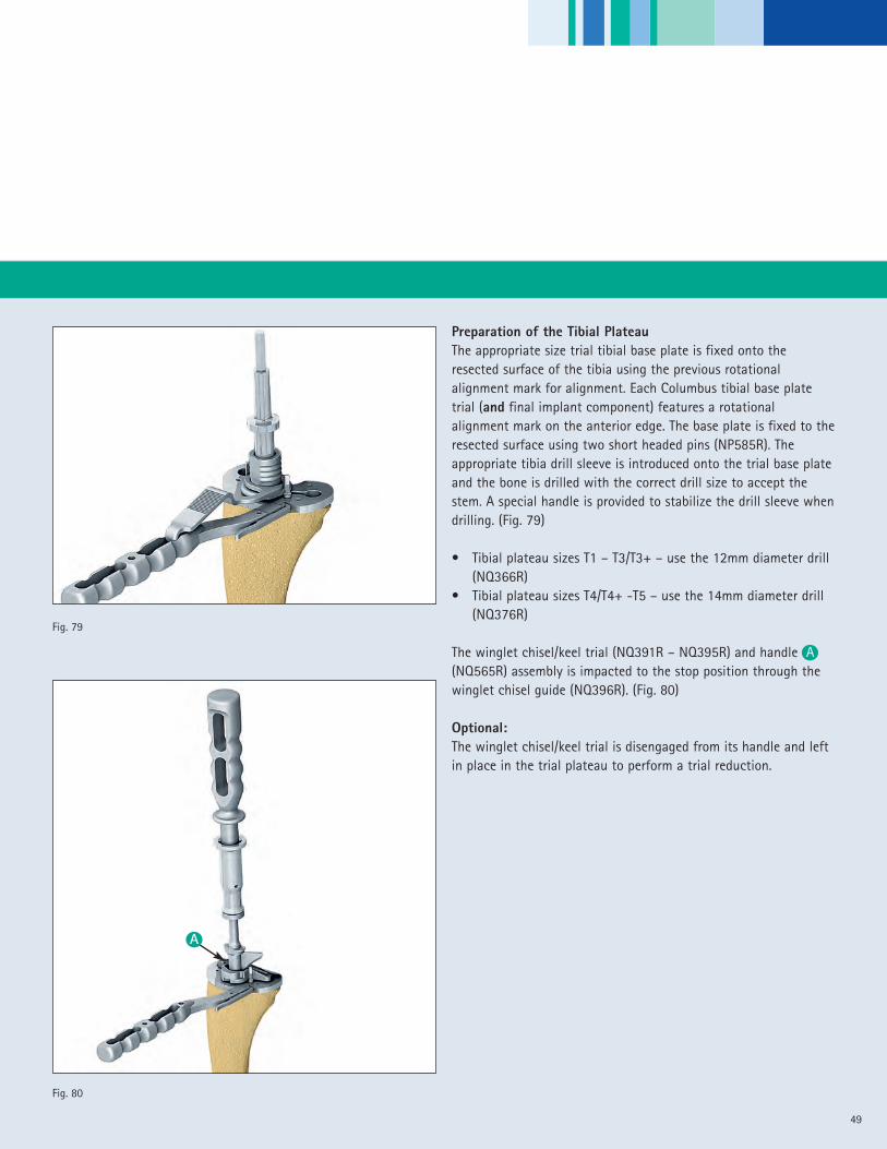
Preparation of the Tibial PlateauThe appropriate size trial tibial base plate is fixed onto theresected surface of the tibia using the previous rotationalalignment mark for alignment. Each Columbus tibial base platetrial (and final implant component) features a rotationalalignment mark on the anterior edge. The base plate is fixed to theresected surface using two short headed pins (NP585R). Theappropriate tibia drill sleeve is introduced onto the trial base plateand the bone is drilled with the correct drill size to accept thestem. A special handle is provided to stabilize the drill sleeve whendrilling. (Fig. 79)
• Tibial plateau sizes T1 – T3/T3+ – use the 12mm diameter drill(NQ366R)
• Tibial plateau sizes T4/T4+ -T5 – use the 14mm diameter drill(NQ376R)
The winglet chisel/keel trial (NQ391R – NQ395R) and handle A(NQ565R) assembly is impacted to the stop position through thewinglet chisel guide (NQ396R). (Fig. 80)
Optional:The winglet chisel/keel trial is disengaged from its handle and leftin place in the trial plateau to perform a trial reduction.
A
Gap Balancing Technique - Tibia First
50
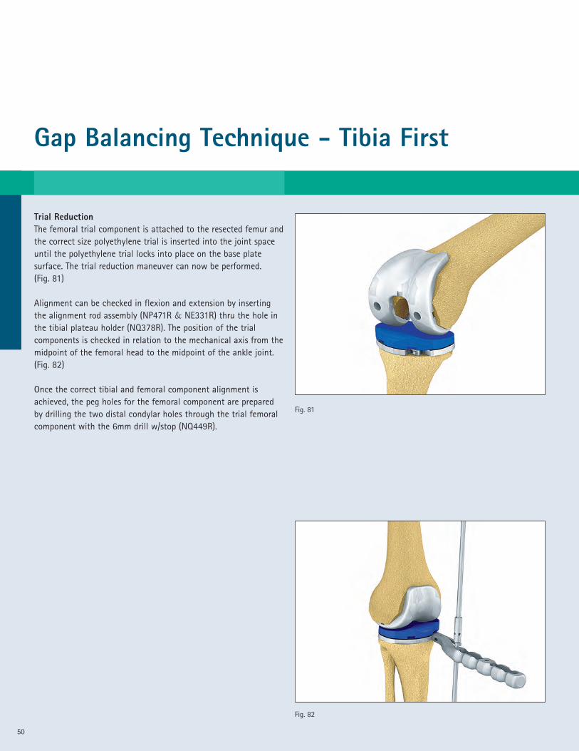
Trial ReductionThe femoral trial component is attached to the resected femur andthe correct size polyethylene trial is inserted into the joint spaceuntil the polyethylene trial locks into place on the base platesurface. The trial reduction maneuver can now be performed.(Fig. 81)
Alignment can be checked in flexion and extension by insertingthe alignment rod assembly (NP471R & NE331R) thru the hole inthe tibial plateau holder (NQ378R). The position of the trialcomponents is checked in relation to the mechanical axis from themidpoint of the femoral head to the midpoint of the ankle joint.(Fig. 82)
Once the correct tibial and femoral component alignment isachieved, the peg holes for the femoral component are preparedby drilling the two distal condylar holes through the trial femoralcomponent with the 6mm drill w/stop (NQ449R).
Fig. 81
Fig. 82

51
Fig. 84
Fig. 83
Fig. 86
Fig. 85
Optional:Posterior Stabilized Technique (PS Implant)The PS box cut is prepared using the appropriate size PS femoralbox preparation guide (NQ571R – NQ577R). The guide is placedonto the resected femur into the peg holes previously drilled. It isstabilized with two headed threaded pins (NP585R). (Fig. 83)
The 14mm diameter drill sleeve (NQ589R) is attached to thefemoral box preparation guide using the medial and lateral holesin the guide. Both corners are drilled using the 14mm drill w/stop(NQ590R). (Fig. 84)
The 22mm diameter drill sleeve (NQ591R) is then introduced ontothe guide and the center box position is drilled using the 22mmdiameter drill (NQ592R). (Fig. 85)
The drill guide is removed and the medial and lateral walls of thebox are finished using the chamfered chisel (NQ593R). The chiselis used with the chamfers facing toward the center of the box.(Fig. 86)
Gap Balancing Technique - Tibia First
52
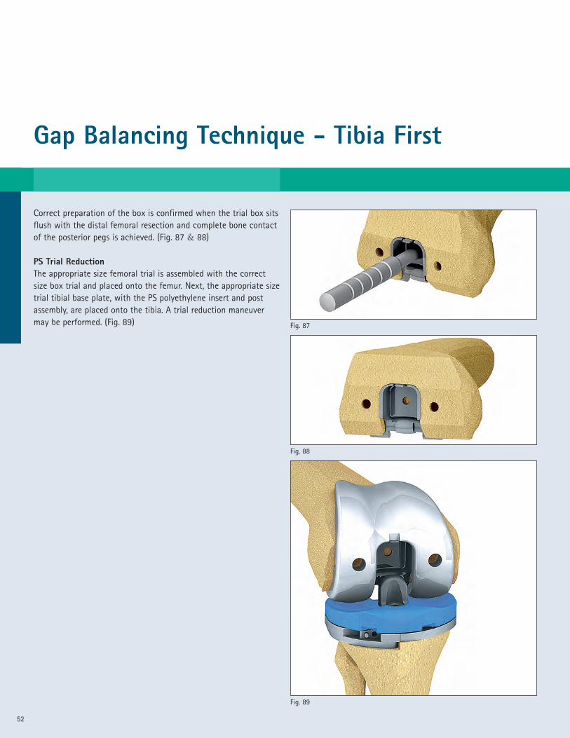
Correct preparation of the box is confirmed when the trial box sitsflush with the distal femoral resection and complete bone contactof the posterior pegs is achieved. (Fig. 87 & 88)
PS Trial ReductionThe appropriate size femoral trial is assembled with the correctsize box trial and placed onto the femur. Next, the appropriate sizetrial tibial base plate, with the PS polyethylene insert and postassembly, are placed onto the tibia. A trial reduction maneuvermay be performed. (Fig. 89)
Fig. 89
Fig. 88
Fig. 87
53
A
Fig. 92
Fig. 91
Fig. 90
B
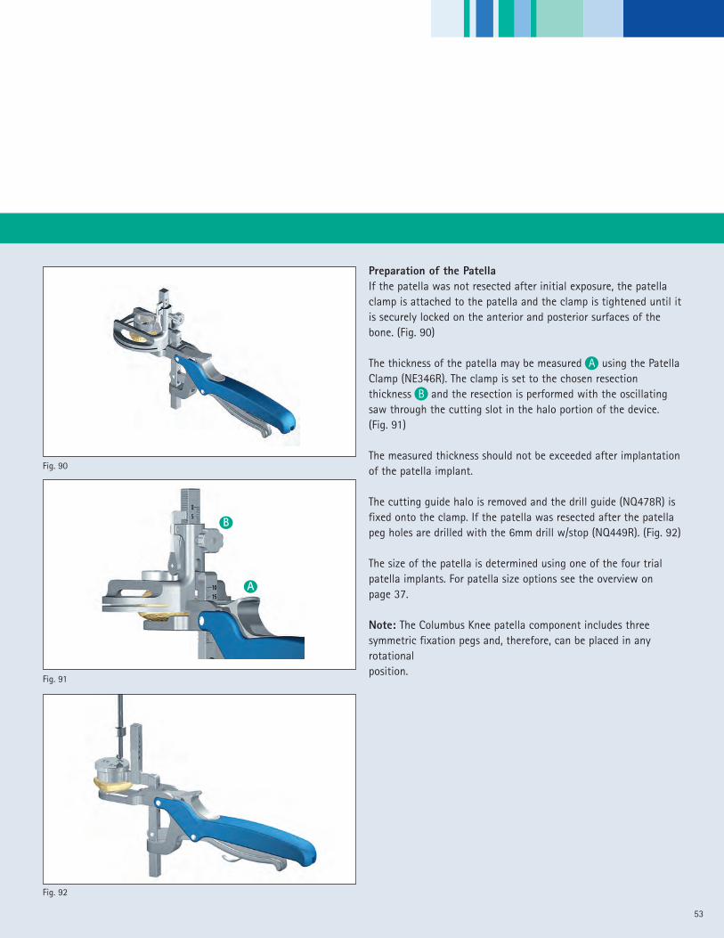
Preparation of the PatellaIf the patella was not resected after initial exposure, the patellaclamp is attached to the patella and the clamp is tightened until itis securely locked on the anterior and posterior surfaces of thebone. (Fig. 90)
The thickness of the patella may be measured A using the PatellaClamp (NE346R). The clamp is set to the chosen resectionthickness B and the resection is performed with the oscillatingsaw through the cutting slot in the halo portion of the device.(Fig. 91)
The measured thickness should not be exceeded after implantationof the patella implant.
The cutting guide halo is removed and the drill guide (NQ478R) isfixed onto the clamp. If the patella was resected after the patellapeg holes are drilled with the 6mm drill w/stop (NQ449R). (Fig. 92)
The size of the patella is determined using one of the four trialpatella implants. For patella size options see the overview onpage 37.
Note: The Columbus Knee patella component includes threesymmetric fixation pegs and, therefore, can be placed in anyrotationalposition.

Gap Balancing Technique - Tibia First
54
Final Implant positioningThe Columbus femoral and tibial implants are available incemented and non-cemented designs. The surgeon can select theappropriate implant design based on the bone quality and hispersonal preference.
The following implantation sequence is recommended:• Tibial Plateau• Femur• Polyethylene• Patella
The tibial plateau is connected to the Impactor/Holder assembly(NQ565R & NQ399R) and impacted precisely into the previouslyprepared proximal tibia. (Fig. 93)
A trial gliding surface may be placed onto the final tibial baseplate to help protect the femoral implant from any damage duringfinal implantation.
The femoral implant is oriented onto the distal femur using thefemoral implant holder assembly (NQ560R & NQ565R). After thecorrect flexion and M/L alignment is confirmed, the femur isimpacted into its final position insuring that the component isfully seated and stable. (Fig. 94)
The patella is implanted using the patella clamp (NE346R). Aspecial plastic cement adapter (NE347) is provided to maintainpressure on the implant while waiting for the cement to dry.(Fig. 95)
The Columbus Knee polyethylene trial implants may be used toconduct a final assessment of the implant position, joint stability,and gap balance prior to selection of the actual polyethyleneinsert.
Fig. 95
Fig. 94
Fig. 93
55
Fig. 96
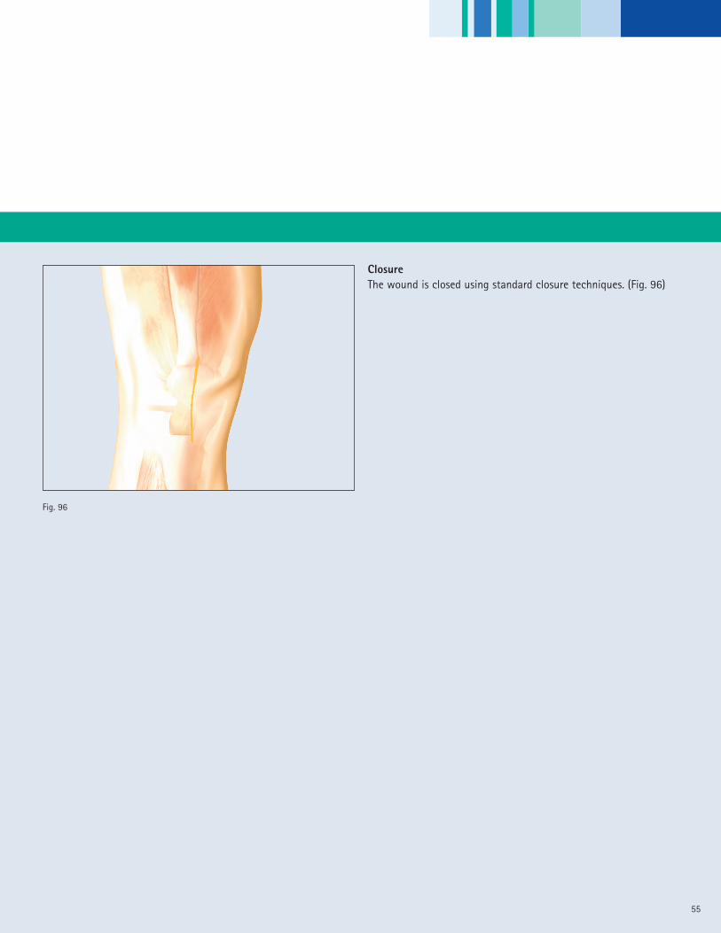
ClosureThe wound is closed using standard closure techniques. (Fig. 96)
56
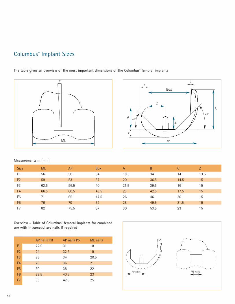
Columbus® Implant Sizes
Size ML AP Box A B C Z
F1 56 50 34 18.5 34 14 13.5
F2 59 53 37 20 36.5 14.5 15
F3 62.5 56.5 40 21.5 39.5 16 15
F4 66.5 60.5 43.5 23 42.5 17.5 15
F5 71 65 47.5 26 46 20 15
F6 76 70 52 28 49.5 21.5 15
F7 82 75.5 57 30 53.5 23 15
8
Box
45°
9
AP
C
Z
3°
45°
B
AP nails ML nails
The table gives an overview of the most important dimensions of the Columbus® femoral implants
A
Measurements in [mm]
ML
7°
Overview – Table of Columbus® femoral implants for combineduse with intramedullary nails if required
AP nails CR AP nails PS ML nails
F1 22.5 31 18
F2 24 32.5 19
F3 26 34 20.5
F4 28 36 21
F5 30 38 22
F6 32.5 40.5 23
F7 35 42.5 25
57
92
52
E
D
A
B
C
4
DPatella
H
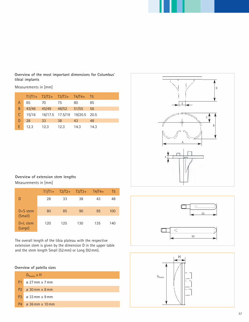
Overview of the most important dimensions for Columbus®
tibial implants
T1/T1+ T2/T2+ T3/T3+ T4/T4+ T5
A 65 70 75 80 85
B 43/46 45/49 48/52 51/55 56
C 15/16 16/17.5 17.5/19 19/20.5 20.5
D 28 33 38 43 48
E 12.3 12.3 12.3 14.3 14.3
The overall length of the tibia plateau with the respectiveextension stem is given by the dimension D in the upper tableand the stem length Small (52mm) or Long (92mm).
Measurements in [mm]
Overview of patella sizes
DPatella x H
P1 ø 27 mm x 7 mm
P2 ø 30 mm x 8 mm
P3 ø 33 mm x 9 mm
P4 ø 36 mm x 10 mm
Overview of extension stem lengths
T1/T1+ T2/T2+ T3/T3+ T4/T4+ T5
D 28 33 38 43 48
D+S stem 80 85 90 95 100(Small)
D+L stem 120 125 130 135 140(Large)
Measurements in [mm]

58
Femoral Component CR Cruciate Retraining Cemented
NN001K Columbus® CR Femur F1LNN002K Columbus® CR Femur F2LNN003K Columbus® CR Femur F3LNN004K Columbus® CR Femur F4LNN005K Columbus® CR Femur F5LNN006K Columbus® CR Femur F6LNN007K Columbus® CR Femur F7LNN011K Columbus® CR Femur F1RNN012K Columbus® CR Femur F2RNN013K Columbus® CR Femur F3RNN014K Columbus® CR Femur F4RNN015K Columbus® CR Femur F5RNN016K Columbus® CR Femur F6RNN017K Columbus® CR Femur F7R
Femoral Component CR Cruciate Retraining CementlessNN021K Columbus® CR Femur F1L PlasmaporeNN022K Columbus® CR Femur F2L PlasmaporeNN023K Columbus® CR Femur F3L PlasmaporeNN024K Columbus® CR Femur F4L PlasmaporeNN025K Columbus® CR Femur F5L PlasmaporeNN026K Columbus® CR Femur F6L PlasmaporeNN027K Columbus® CR Femur F7L PlasmaporeNN031K Columbus® CR Femur F1R PlasmaporeNN032K Columbus® CR Femur F2R PlasmaporeNN033K Columbus® CR Femur F3R PlasmaporeNN034K Columbus® CR Femur F4R PlasmaporeNN035K Columbus® CR Femur F5R PlasmaporeNN036K Columbus® CR Femur F6R PlasmaporeNN037K Columbus® CR Femur F7R Plasmapore
Femoral Component PS Posterior Stabilized Cemented
NN161K Columbus® PS Femur F1L NN162K Columbus® PS Femur F2L NN163K Columbus® PS Femur F3L NN164K Columbus® PS Femur F4L NN165K Columbus® PS Femur F5L NN166K Columbus® PS Femur F6L NN167K Columbus® PS Femur F7L NN171K Columbus® PS Femur F1R NN172K Columbus® PS Femur F2R NN173K Columbus® PS Femur F3R NN174K Columbus® PS Femur F4R NN175K Columbus® PS Femur F5R NN176K Columbus® PS Femur F6R NN177K Columbus® PS Femur F7R
Columbus ® Order ing Informat ion

59
Tibia Plateau CR/PS Cruciate Retraining/Posterior Stabilized Modular, Cemented
NN071K Columbus® CR/PS Tibia Plateau T1NN072K Columbus® CR/PS Tibia Plateau T1+NN073K Columbus® CR/PS Tibia Plateau T2NN074K Columbus® CR/PS Tibia Plateau T2+NN075K Columbus® CR/PS Tibia Plateau T3NN076K Columbus® CR/PS Tibia Plateau T3+NN077K Columbus® CR/PS Tibia Plateau T4NN078K Columbus® CR/PS Tibia Plateau T4+NN079K Columbus® CR/PS Tibia Plateau T5
Tibia Plateau CR/PS Cruciate Retraining/Posterior Stabilized Modular, Cementless
NN081K Columbus® CR/PS Tibia Plateau T1 PlasmaporeNN082K Columbus® CR/PS Tibia Plateau T1+ PlasmaporeNN083K Columbus® CR/PS Tibia Plateau T2 PlasmaporeNN084K Columbus® CR/PS Tibia Plateau T2+ PlasmaporeNN085K Columbus® CR/PS Tibia Plateau T3 PlasmaporeNN086K Columbus® CR/PS Tibia Plateau T3+ PlasmaporeNN087K Columbus® CR/PS Tibia Plateau T4 PlasmaporeNN088K Columbus® CR/PS Tibia Plateau T4+ PlasmaporeNN089K Columbus® CR/PS Tibia Plateau T5 Plasmapore
60
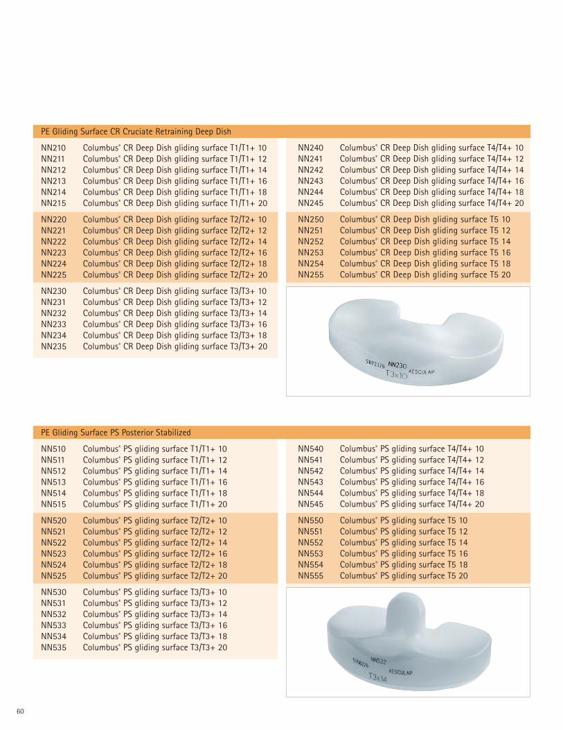
PE Gliding Surface CR Cruciate Retraining Deep Dish
NN210 Columbus® CR Deep Dish gliding surface T1/T1+ 10NN211 Columbus® CR Deep Dish gliding surface T1/T1+ 12NN212 Columbus® CR Deep Dish gliding surface T1/T1+ 14NN213 Columbus® CR Deep Dish gliding surface T1/T1+ 16NN214 Columbus® CR Deep Dish gliding surface T1/T1+ 18NN215 Columbus® CR Deep Dish gliding surface T1/T1+ 20
NN220 Columbus® CR Deep Dish gliding surface T2/T2+ 10NN221 Columbus® CR Deep Dish gliding surface T2/T2+ 12NN222 Columbus® CR Deep Dish gliding surface T2/T2+ 14NN223 Columbus® CR Deep Dish gliding surface T2/T2+ 16NN224 Columbus® CR Deep Dish gliding surface T2/T2+ 18NN225 Columbus® CR Deep Dish gliding surface T2/T2+ 20
NN230 Columbus® CR Deep Dish gliding surface T3/T3+ 10NN231 Columbus® CR Deep Dish gliding surface T3/T3+ 12NN232 Columbus® CR Deep Dish gliding surface T3/T3+ 14NN233 Columbus® CR Deep Dish gliding surface T3/T3+ 16NN234 Columbus® CR Deep Dish gliding surface T3/T3+ 18NN235 Columbus® CR Deep Dish gliding surface T3/T3+ 20
NN240 Columbus® CR Deep Dish gliding surface T4/T4+ 10NN241 Columbus® CR Deep Dish gliding surface T4/T4+ 12NN242 Columbus® CR Deep Dish gliding surface T4/T4+ 14NN243 Columbus® CR Deep Dish gliding surface T4/T4+ 16NN244 Columbus® CR Deep Dish gliding surface T4/T4+ 18NN245 Columbus® CR Deep Dish gliding surface T4/T4+ 20
NN250 Columbus® CR Deep Dish gliding surface T5 10NN251 Columbus® CR Deep Dish gliding surface T5 12NN252 Columbus® CR Deep Dish gliding surface T5 14NN253 Columbus® CR Deep Dish gliding surface T5 16NN254 Columbus® CR Deep Dish gliding surface T5 18NN255 Columbus® CR Deep Dish gliding surface T5 20
PE Gliding Surface PS Posterior Stabilized
NN510 Columbus® PS gliding surface T1/T1+ 10NN511 Columbus® PS gliding surface T1/T1+ 12NN512 Columbus® PS gliding surface T1/T1+ 14NN513 Columbus® PS gliding surface T1/T1+ 16NN514 Columbus® PS gliding surface T1/T1+ 18NN515 Columbus® PS gliding surface T1/T1+ 20
NN520 Columbus® PS gliding surface T2/T2+ 10NN521 Columbus® PS gliding surface T2/T2+ 12NN522 Columbus® PS gliding surface T2/T2+ 14NN523 Columbus® PS gliding surface T2/T2+ 16NN524 Columbus® PS gliding surface T2/T2+ 18NN525 Columbus® PS gliding surface T2/T2+ 20
NN530 Columbus® PS gliding surface T3/T3+ 10NN531 Columbus® PS gliding surface T3/T3+ 12NN532 Columbus® PS gliding surface T3/T3+ 14NN533 Columbus® PS gliding surface T3/T3+ 16NN534 Columbus® PS gliding surface T3/T3+ 18NN535 Columbus® PS gliding surface T3/T3+ 20
NN540 Columbus® PS gliding surface T4/T4+ 10NN541 Columbus® PS gliding surface T4/T4+ 12NN542 Columbus® PS gliding surface T4/T4+ 14NN543 Columbus® PS gliding surface T4/T4+ 16NN544 Columbus® PS gliding surface T4/T4+ 18NN545 Columbus® PS gliding surface T4/T4+ 20
NN550 Columbus® PS gliding surface T5 10NN551 Columbus® PS gliding surface T5 12NN552 Columbus® PS gliding surface T5 14NN553 Columbus® PS gliding surface T5 16NN554 Columbus® PS gliding surface T5 18NN555 Columbus® PS gliding surface T5 20

61
Columbus® Obturator Screws
NN261K Obturator screw D 12 For plateau 1–3+NN264K Obturator screw D 14 For plateau 4-5
Columbus® Extension Stems
NN262K stem D 12 S For plateau 1–3+NN263K stem D 12 L For plateau 1–3+NN265K stem D 14 S For plateau 4 -5NN266K stem D 14 L For plateau 4 -5
Columbus® Patella
NN481 P1 Patella size 1 Ø 27 mm x 7 mmNN482 P2 Patella size 2 Ø 30 mm x 8 mmNN483 P3 Patella size 3 Ø 33 mm x 9 mmNN484 P4 Patella size 4 Ø 36 mm x 10 mm
62
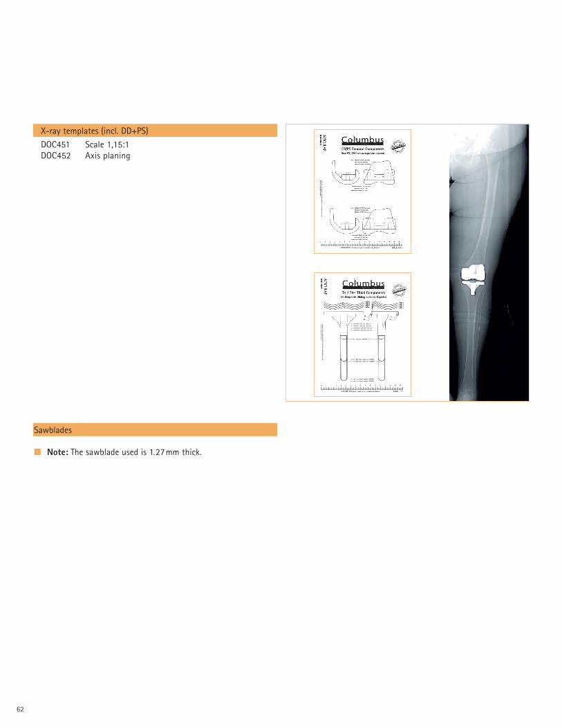
X-ray templates (incl. DD+PS)
DOC451 Scale 1,15:1DOC452 Axis planing
Sawblades
� Note: The sawblade used is 1.27mm thick.

63

Aesculap Implant Systems, Inc.
3773 Corporate ParkwayCenter Valley, PA 18034Phone: 866-229-3002
http://www.aesculapimplantsystems.com©2007 AESCULAP. ALL RIGHTS RESERVED. PRINTED IN THE USA. DOC620 1M 3/07Aesculap is an equal opportunity employer
All rights reserved. Technical alterations are possible. The information provided in thisleaflet is distributed by Aesculap Implant Systems, Inc. for educational purposes andnot for the purpose of rendering medical advice. The material in this leaflet is notinstructional and should NOT be relied upon by surgeons and staff as adequatetraining for performing the surgeries illustrated. This brochure is intended for healthcare professionals and employees, not for patients. The information presented is not asubstitute for a medical examination and opinion by a licensed physician regarding apatient’s diagnosis or recommended course of treatment. This leaflet may be used forno other purposes than offering, buying and selling of our products. No part may becopied or reproduced in any form. In the case of misuse we retain the rights to recallour catalogs and price lists and to take legal actions.