Embed Size (px)
Citation preview
www.tektronix.com071-1631-00
AFG3000 SeriesArbitrary/Function GeneratorsQuick Start User Manual

Copyright © Tektronix, Inc. All rights reserved.
Tektronix products are covered by U.S. and foreign patents, issued and pending. Information in this publication supercedes that in all previously published material. Specifications and price change privileges reserved.
Tektronix, Inc., P.O.Box 500, Beaverton, OR 97077
TEKTRONIX and TEK are registered trademarks of Tektronix, Inc.

Warranty 16
Tektronix warrants that the product will be free from defects in materials and workmanship for a period of three (3) years from the date of original purchase from an authorized Tektronix distributor. If the product proves defective during this warranty period, Tektronix, at its option, either will repair the defective product without charge for parts and labor, or will provide a replacement in exchange for the defective product. Batteries are excluded from this warranty. Parts, modules and replacement products used by Tektronix for warranty work may be new or reconditioned to like new performance. All replaced parts, modules and products become the property of Tektronix.
In order to obtain service under this warranty, Customer must notify Tektronix of the defect before the expiration of the warranty period and make suitable arrangements for the performance of service. Customer shall be responsible for packaging and shipping the defective product to the service center designated by Tektronix, shipping charges prepaid, and with a copy of customer proof of purchase. Tektronix shall pay for the return of the product to Customer if the shipment is to a location within the country in which the Tektronix service center is located. Customer shall be responsible for paying all shipping charges, duties, taxes, and any other charges for products returned to any other locations.
This warranty shall not apply to any defect, failure or damage caused by improper use or improper or inadequate maintenance and care. Tektronix shall not be obligated to furnish service under this warranty a) to repair damage resulting from attempts by personnel other than Tektronix representatives to install, repair or service the product; b) to repair damage resulting from improper use or connection to incompatible equipment; c) to repair any damage or malfunction caused by the use of non-Tektronix supplies; or d) to service a product that has been modified or integrated with other products when the effect of such modification or integration increases the time or difficulty of servicing the product.
THIS WARRANTY IS GIVEN BY TEKTRONIX WITH RESPECT TO THE PRODUCT IN LIEU OF ANY OTHER WARRANTIES, EXPRESS OR IMPLIED. TEKTRONIX AND ITS VENDORS DISCLAIM ANY IMPLIED WARRANTIES OF MERCHANTABILITY OR FITNESS FOR A PARTICULAR PURPOSE. TEKTRONIX' RESPONSIBILITY TO REPAIR OR REPLACE DEFECTIVE PRODUCTS IS THE SOLE AND EXCLUSIVE REMEDY PROVIDED TO THE CUSTOMER FOR BREACH OF THIS WARRANTY. TEKTRONIX AND ITS VENDORS WILL NOT BE LIABLE FOR ANY INDIRECT, SPECIAL, INCIDENTAL, OR CONSEQUENTIAL DAMAGES IRRESPECTIVE OF WHETHER TEKTRONIX OR THE VENDOR HAS ADVANCE NOTICE OF THE POSSIBILITY OF SUCH DAMAGES.

Table of Contents
Table of ContentsGeneral Safety Summary . . . . . . . . . . . . . . . . . . . . . . . . . . . . . . . . . . . . . . . . . . . . . . . . . . . . . . . . . . . . . . . . . . . . . . . . . . . . . . . . iii
Preface . . . . . . . . . . . . . . . . . . . . . . . . . . . . . . . . . . . . . . . . . . . . . . . . . . . . . . . . . . . . . . . . . . . . . . . . . . . . . . . . . . . . . . . . . . . . . . vDocumentation. . . . . . . . . . . . . . . . . . . . . . . . . . . . . . . . . . . . . . . . . . . . . . . . . . . . . . . . . . . . . . . . . . . . . . . . . . . . . . . . . . . . . vConventions Used in this Manual. . . . . . . . . . . . . . . . . . . . . . . . . . . . . . . . . . . . . . . . . . . . . . . . . . . . . . . . . . . . . . . . . . . . . . . viContacting Tektronix . . . . . . . . . . . . . . . . . . . . . . . . . . . . . . . . . . . . . . . . . . . . . . . . . . . . . . . . . . . . . . . . . . . . . . . . . . . . . . . . vi
Quick Tutorial . . . . . . . . . . . . . . . . . . . . . . . . . . . . . . . . . . . . . . . . . . . . . . . . . . . . . . . . . . . . . . . . . . . . . . . . . . . . . . . . . . . . . . . . . 1To Generate a Sine Waveform . . . . . . . . . . . . . . . . . . . . . . . . . . . . . . . . . . . . . . . . . . . . . . . . . . . . . . . . . . . . . . . . . . . . . . . . . 2Accessing Help . . . . . . . . . . . . . . . . . . . . . . . . . . . . . . . . . . . . . . . . . . . . . . . . . . . . . . . . . . . . . . . . . . . . . . . . . . . . . . . . . . . . 4
Getting Started . . . . . . . . . . . . . . . . . . . . . . . . . . . . . . . . . . . . . . . . . . . . . . . . . . . . . . . . . . . . . . . . . . . . . . . . . . . . . . . . . . . . . . . . 5General Features . . . . . . . . . . . . . . . . . . . . . . . . . . . . . . . . . . . . . . . . . . . . . . . . . . . . . . . . . . . . . . . . . . . . . . . . . . . . . . . . . . . 5Before Installation . . . . . . . . . . . . . . . . . . . . . . . . . . . . . . . . . . . . . . . . . . . . . . . . . . . . . . . . . . . . . . . . . . . . . . . . . . . . . . . . . . 6Operating Requirements . . . . . . . . . . . . . . . . . . . . . . . . . . . . . . . . . . . . . . . . . . . . . . . . . . . . . . . . . . . . . . . . . . . . . . . . . . . . . 6Standard Accessories . . . . . . . . . . . . . . . . . . . . . . . . . . . . . . . . . . . . . . . . . . . . . . . . . . . . . . . . . . . . . . . . . . . . . . . . . . . . . . . 7Powering the Instrument On and Off . . . . . . . . . . . . . . . . . . . . . . . . . . . . . . . . . . . . . . . . . . . . . . . . . . . . . . . . . . . . . . . . . . . . 8Self Test and Self Calibration. . . . . . . . . . . . . . . . . . . . . . . . . . . . . . . . . . . . . . . . . . . . . . . . . . . . . . . . . . . . . . . . . . . . . . . . . . 9Selecting a Local Language . . . . . . . . . . . . . . . . . . . . . . . . . . . . . . . . . . . . . . . . . . . . . . . . . . . . . . . . . . . . . . . . . . . . . . . . . 10Protect Your Instrument from Misuse . . . . . . . . . . . . . . . . . . . . . . . . . . . . . . . . . . . . . . . . . . . . . . . . . . . . . . . . . . . . . . . . . . . 11Floating Ground . . . . . . . . . . . . . . . . . . . . . . . . . . . . . . . . . . . . . . . . . . . . . . . . . . . . . . . . . . . . . . . . . . . . . . . . . . . . . . . . . . . 12Protect Your DUT . . . . . . . . . . . . . . . . . . . . . . . . . . . . . . . . . . . . . . . . . . . . . . . . . . . . . . . . . . . . . . . . . . . . . . . . . . . . . . . . . . 13Update Your Instrument Firmware . . . . . . . . . . . . . . . . . . . . . . . . . . . . . . . . . . . . . . . . . . . . . . . . . . . . . . . . . . . . . . . . . . . . . 14Connect to a Network . . . . . . . . . . . . . . . . . . . . . . . . . . . . . . . . . . . . . . . . . . . . . . . . . . . . . . . . . . . . . . . . . . . . . . . . . . . . . . 15
Getting Acquainted with Your Instrument . . . . . . . . . . . . . . . . . . . . . . . . . . . . . . . . . . . . . . . . . . . . . . . . . . . . . . . . . . . . . . . . . . . 19Front Panel Overview. . . . . . . . . . . . . . . . . . . . . . . . . . . . . . . . . . . . . . . . . . . . . . . . . . . . . . . . . . . . . . . . . . . . . . . . . . . . . . . 19Screen Interface . . . . . . . . . . . . . . . . . . . . . . . . . . . . . . . . . . . . . . . . . . . . . . . . . . . . . . . . . . . . . . . . . . . . . . . . . . . . . . . . . . 20View Button . . . . . . . . . . . . . . . . . . . . . . . . . . . . . . . . . . . . . . . . . . . . . . . . . . . . . . . . . . . . . . . . . . . . . . . . . . . . . . . . . . . . . . 21Shortcut Buttons . . . . . . . . . . . . . . . . . . . . . . . . . . . . . . . . . . . . . . . . . . . . . . . . . . . . . . . . . . . . . . . . . . . . . . . . . . . . . . . . . . 22Default Setup . . . . . . . . . . . . . . . . . . . . . . . . . . . . . . . . . . . . . . . . . . . . . . . . . . . . . . . . . . . . . . . . . . . . . . . . . . . . . . . . . . . . . 23Select Waveform . . . . . . . . . . . . . . . . . . . . . . . . . . . . . . . . . . . . . . . . . . . . . . . . . . . . . . . . . . . . . . . . . . . . . . . . . . . . . . . . . . 24Select Run Mode . . . . . . . . . . . . . . . . . . . . . . . . . . . . . . . . . . . . . . . . . . . . . . . . . . . . . . . . . . . . . . . . . . . . . . . . . . . . . . . . . . 26Adjust Waveform Parameters. . . . . . . . . . . . . . . . . . . . . . . . . . . . . . . . . . . . . . . . . . . . . . . . . . . . . . . . . . . . . . . . . . . . . . . . . 27Channel Select (dual-channel model only) . . . . . . . . . . . . . . . . . . . . . . . . . . . . . . . . . . . . . . . . . . . . . . . . . . . . . . . . . . . . . . 29Output ON/OFF . . . . . . . . . . . . . . . . . . . . . . . . . . . . . . . . . . . . . . . . . . . . . . . . . . . . . . . . . . . . . . . . . . . . . . . . . . . . . . . . . . . 29Rear Panel . . . . . . . . . . . . . . . . . . . . . . . . . . . . . . . . . . . . . . . . . . . . . . . . . . . . . . . . . . . . . . . . . . . . . . . . . . . . . . . . . . . . . . . 30
Operating Basics . . . . . . . . . . . . . . . . . . . . . . . . . . . . . . . . . . . . . . . . . . . . . . . . . . . . . . . . . . . . . . . . . . . . . . . . . . . . . . . . . . . . . 31Generate a Pulse Waveform . . . . . . . . . . . . . . . . . . . . . . . . . . . . . . . . . . . . . . . . . . . . . . . . . . . . . . . . . . . . . . . . . . . . . . . . . 31Generate an Arbitrary Waveform . . . . . . . . . . . . . . . . . . . . . . . . . . . . . . . . . . . . . . . . . . . . . . . . . . . . . . . . . . . . . . . . . . . . . . 32Modify an Arbitrary Waveform (Edit Menu) . . . . . . . . . . . . . . . . . . . . . . . . . . . . . . . . . . . . . . . . . . . . . . . . . . . . . . . . . . . . . . 33Generate Noise/DC . . . . . . . . . . . . . . . . . . . . . . . . . . . . . . . . . . . . . . . . . . . . . . . . . . . . . . . . . . . . . . . . . . . . . . . . . . . . . . . . 35Generate a Burst Waveform. . . . . . . . . . . . . . . . . . . . . . . . . . . . . . . . . . . . . . . . . . . . . . . . . . . . . . . . . . . . . . . . . . . . . . . . . . 36Generate a Gated Waveform . . . . . . . . . . . . . . . . . . . . . . . . . . . . . . . . . . . . . . . . . . . . . . . . . . . . . . . . . . . . . . . . . . . . . . . . . 37Sweep a Waveform . . . . . . . . . . . . . . . . . . . . . . . . . . . . . . . . . . . . . . . . . . . . . . . . . . . . . . . . . . . . . . . . . . . . . . . . . . . . . . . . 38Modulate a Waveform . . . . . . . . . . . . . . . . . . . . . . . . . . . . . . . . . . . . . . . . . . . . . . . . . . . . . . . . . . . . . . . . . . . . . . . . . . . . . . 40Trigger Out . . . . . . . . . . . . . . . . . . . . . . . . . . . . . . . . . . . . . . . . . . . . . . . . . . . . . . . . . . . . . . . . . . . . . . . . . . . . . . . . . . . . . . . 43Adjusting Parameters of Two Channel Signals (dual-channel model only). . . . . . . . . . . . . . . . . . . . . . . . . . . . . . . . . . . . . . . 44Set up Load Impedance. . . . . . . . . . . . . . . . . . . . . . . . . . . . . . . . . . . . . . . . . . . . . . . . . . . . . . . . . . . . . . . . . . . . . . . . . . . . . 46Invert Waveform. . . . . . . . . . . . . . . . . . . . . . . . . . . . . . . . . . . . . . . . . . . . . . . . . . . . . . . . . . . . . . . . . . . . . . . . . . . . . . . . . . . 47Add Noise . . . . . . . . . . . . . . . . . . . . . . . . . . . . . . . . . . . . . . . . . . . . . . . . . . . . . . . . . . . . . . . . . . . . . . . . . . . . . . . . . . . . . . . 48Add Signal (AFG3100 and AFG3200 Series) . . . . . . . . . . . . . . . . . . . . . . . . . . . . . . . . . . . . . . . . . . . . . . . . . . . . . . . . . . . . 49External Reference Clock (AFG3100 and AFG3200 Series) . . . . . . . . . . . . . . . . . . . . . . . . . . . . . . . . . . . . . . . . . . . . . . . . . 50
AFG3000 Series Quick Start User Manual i
Table of Contents
Synchronous Operation (AFG3100 and AFG3200 Series) . . . . . . . . . . . . . . . . . . . . . . . . . . . . . . . . . . . . . . . . . . . . . . . . . . 51USB Memory . . . . . . . . . . . . . . . . . . . . . . . . . . . . . . . . . . . . . . . . . . . . . . . . . . . . . . . . . . . . . . . . . . . . . . . . . . . . . . . . . . . . . 52Utility Menu . . . . . . . . . . . . . . . . . . . . . . . . . . . . . . . . . . . . . . . . . . . . . . . . . . . . . . . . . . . . . . . . . . . . . . . . . . . . . . . . . . . . . . 53Save/Recall Instrument Setup . . . . . . . . . . . . . . . . . . . . . . . . . . . . . . . . . . . . . . . . . . . . . . . . . . . . . . . . . . . . . . . . . . . . . . . . 55ArbExpress . . . . . . . . . . . . . . . . . . . . . . . . . . . . . . . . . . . . . . . . . . . . . . . . . . . . . . . . . . . . . . . . . . . . . . . . . . . . . . . . . . . . . . 56
Application Examples . . . . . . . . . . . . . . . . . . . . . . . . . . . . . . . . . . . . . . . . . . . . . . . . . . . . . . . . . . . . . . . . . . . . . . . . . . . . . . . . . . 57Lissajous Patterns . . . . . . . . . . . . . . . . . . . . . . . . . . . . . . . . . . . . . . . . . . . . . . . . . . . . . . . . . . . . . . . . . . . . . . . . . . . . . . . . . 57Measurement of Filter Characteristics . . . . . . . . . . . . . . . . . . . . . . . . . . . . . . . . . . . . . . . . . . . . . . . . . . . . . . . . . . . . . . . . . . 58Motor Speed Control by Pulse-Width Modulation . . . . . . . . . . . . . . . . . . . . . . . . . . . . . . . . . . . . . . . . . . . . . . . . . . . . . . . . . 59Carrier Null (Frequency Modulation) . . . . . . . . . . . . . . . . . . . . . . . . . . . . . . . . . . . . . . . . . . . . . . . . . . . . . . . . . . . . . . . . . . . 60
Specifications . . . . . . . . . . . . . . . . . . . . . . . . . . . . . . . . . . . . . . . . . . . . . . . . . . . . . . . . . . . . . . . . . . . . . . . . . . . . . . . . . . . . . . . . 61Electrical . . . . . . . . . . . . . . . . . . . . . . . . . . . . . . . . . . . . . . . . . . . . . . . . . . . . . . . . . . . . . . . . . . . . . . . . . . . . . . . . . . . . . . . . 61Inputs/Outputs . . . . . . . . . . . . . . . . . . . . . . . . . . . . . . . . . . . . . . . . . . . . . . . . . . . . . . . . . . . . . . . . . . . . . . . . . . . . . . . . . . . . 66General . . . . . . . . . . . . . . . . . . . . . . . . . . . . . . . . . . . . . . . . . . . . . . . . . . . . . . . . . . . . . . . . . . . . . . . . . . . . . . . . . . . . . . . . . 67Instrument Dimensions . . . . . . . . . . . . . . . . . . . . . . . . . . . . . . . . . . . . . . . . . . . . . . . . . . . . . . . . . . . . . . . . . . . . . . . . . . . . . 68
Index . . . . . . . . . . . . . . . . . . . . . . . . . . . . . . . . . . . . . . . . . . . . . . . . . . . . . . . . . . . . . . . . . . . . . . . . . . . . . . . . . . . . . . . . . . . . . . . 69
ii AFG3000 Series Quick Start User Manual
General Safety Summary
General Safety SummaryReview the following safety precautions to avoid injury and prevent damage to this product or any products connected to it. To avoid potential hazards, use this product only as specified.
Only qualified personnel should perform service procedures.
To avoid Fire or Personal Injury
Use Proper Power Cord. Use only the power cord specified for this product and certified for the country of use.
Ground the Product. This product is grounded through the grounding conductor of the power cord. To avoid electric shock, the grounding conductor must be connected to earth ground. Before making connections to the input or output ter-minals of the product, ensure that the product is properly grounded.
Observe All Terminal Ratings. To avoid fire or shock hazard, observe all ratings and markings on the product. Consult the product manual for further rating information before making connections to the product. Do not apply a potential to any terminal, including the common terminal, that exceeds the maximum rating of that terminal.
Power Off. The power cord provides Mains disconnect.
Do Not Operate Without Covers. Do not operate this product with covers or panels removed.
Do Not Operate With Suspected Failures. If you suspect there is damage to this product, have it inspected by qual-ified service personnel.
Do Not Operate in Wet/Damp Conditions.
Do Not Operate in an Explosive Atmosphere.
Keep Product Surfaces Clean and Dry.
Provide Proper Ventilation. Refer to the manual's installation instructions for details on installing the product so it has proper ventilation.
AFG3000 Series Quick Start User Manual iii
General Safety Summary
Symbols and Terms
Terms in this Manual. These terms may appear in this manual:
Terms on the Product. These terms may appear on the product:
DANGER indicates an injury hazard immediately accessible as you read the marking.
WARNING indicates an injury hazard not immediately accessible as you read the marking.
CAUTION indicates a hazard to property including the product.
WARNING. Warning statements identify conditions or practices that could result in injury or loss of life.
CAUTION. Caution statements identify conditions or practices that could result in damage to this product or other property.
iv AFG3000 Series Quick Start User Manual
Preface
PrefaceThis manual describes the installation and operation of Tektronix AFG3000 Series Arbitrary/Function Generators along with basic operations and concepts. For more detailed information, see the Reference Manual. The following instruments are supported by this manual:
Documentation
The following table lists related documentation available for your arbitrary/function generator. The documentation is avail-able on the Product CD and on the Tektronix web site (www.tektronix.com).
AFG3021 AFG3022 AFG3101
AFG3102 AFG3251 AFG3252
Item Purpose Location
Quick Start User Manual Unpacking, Installation, Specifica-tion, Operation, and Overviews
Built-in Help UI Help and Operation
Reference Manual Menu Structures, User Interface, and Programming Information
Service Manual (Optional) Self-service and Performance test
ArbExpress Software CD Waveform creation
Import waveforms from oscilloscope or PC
?
AFG3000 Series Quick Start User Manual v
Preface
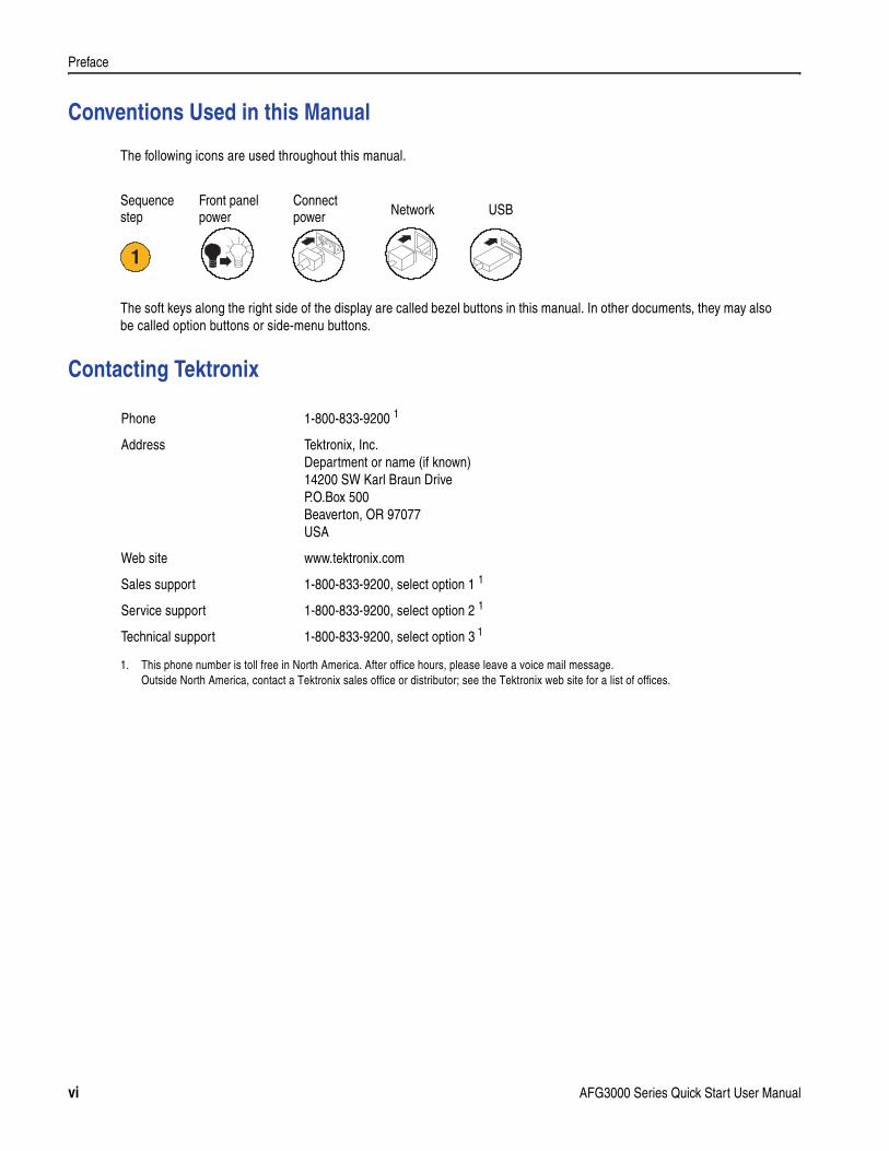
Conventions Used in this Manual
The following icons are used throughout this manual.
The soft keys along the right side of the display are called bezel buttons in this manual. In other documents, they may also be called option buttons or side-menu buttons.
Contacting Tektronix
Front panelpower
Connectpower Network
1
USBSequencestep
Phone 1-800-833-9200 1
1. This phone number is toll free in North America. After office hours, please leave a voice mail message.Outside North America, contact a Tektronix sales office or distributor; see the Tektronix web site for a list of offices.
Address Tektronix, Inc.Department or name (if known)14200 SW Karl Braun DriveP.O.Box 500Beaverton, OR 97077USA
Web site www.tektronix.com
Sales support 1-800-833-9200, select option 1 1
Service support 1-800-833-9200, select option 2 1
Technical support 1-800-833-9200, select option 3 1
vi AFG3000 Series Quick Start User Manual
Quick Tutorial
Quick TutorialThe quick tutorial shows beginning users how to generate a simple sine waveform. Follow these steps to get acquainted with the basics of the instrument:
1. Turn on the arbitrary/function generator.
2. Connect the CH1 Output of the arbitrary/function generator and the oscilloscope input with a BNC cable.
3. Select a waveform.
4. Enable the signal output.
5. Observe a waveform displayed on the oscilloscope screen.
6. Use the front-panel shortcut buttons to select a waveform parameter.
7. Select Frequency as a parameter to be changed.
8. Change the frequency value using numeric keys.
9. You can also change the waveform parameters using the general purpose knob and the arrow keys.
For more task-oriented descriptions of basic operation, see Application Examples on page 57.
In addition to the quick tutorial for generating a sine waveform, this section describes how to access the help system of the arbitrary/function generator.
AFG3000 Series Quick Start User Manual 1
Quick Tutorial
To Generate a Sine Waveform
The following quick tutorial describes how to generate a continuous sine waveform using Tektronix AFG3000 Series Arbi-trary/Function Generators. Follow these steps to learn the basics of the arbitrary/function generator.
1. Connect the power cord, and then push the front-panel power on/off switch to turn on the arbitrary/function generator.
2. Connect a BNC cable from the CH1 Output of arbitrary/function generator to an oscilloscope input connector.
3. Push the front-panel Sine button, and then push the Continuous button to select a waveform.
4. Push the front-panel CH1 Output On button to enable the output.
5. Use the oscilloscope auto-scaling function to display the sine waveform on the screen.
If the instrument outputs a default sine waveform, you can manually set the oscilloscope as follows:
0.5 µs/div
200 mV/div
6. To change the frequency, push the front-panel Frequency/Period short-cut button.
21
AFG3000 series Oscilloscope
3
4
5
6
2 AFG3000 Series Quick Start User Manual
Quick Tutorial
Quick Tips
Use the front-panel shortcut buttons to quickly select a waveform parameter. See page 22 for usage of shortcut buttons.
You can also specify a waveform parameter by using bezel menu selection. This method does not use the front-panel shortcut buttons.
When you specify a waveform parameter using the shortcut buttons or bezel menu selection, an active parameter is displayed in green in the graph area. (See step 8 above.)
7. The Frequency/Period/Phase Menu is displayed and Freq is selected. You can now change the frequency value.
8. To change the frequency value, use the keypad and Units bezel buttons.
For example, if you enter a value "2" using the keypad, the bezel menus will automatically change to Units.
After entering the frequency value, push the Units bezel button or the front-panel Enter button to complete the entry.
You can change the Amplitude, Phase, and Offset values in the same way.
9. You can also change the frequency value using the general purpose knob and the arrow keys.
To increase the value, turn the knob clockwise.
To change a specific digit, select it by pushing the arrow keys. Then change it by turning the knob.
7
8
9
AFG3000 Series Quick Start User Manual 3
Quick Tutorial
Accessing Help
Quick Tips
When you push the Help button, the instrument displays information about the last menu displayed on the screen. If the topic uses more than one page, turn the general purpose knob to move from page to page within the topic.
Most of the help topics contain phrases marked with <angle brackets>. These are links to other topics. Turn the general purpose knob to move the highlight from one link to another. Push the Show Topic bezel button to display the topic corresponding to the highlighted link.
Push the front-panel Help button, then push the Index bezel button to display an Index page. Push the Page Up or Page Down bezel button until you find the index page that contains the topic you want to view. Turn the general purpose knob to highlight a help topic. Push the Show Topic button to display the topic.
Push the Exit bezel button or any front-panel button to remove the Help text from the screen and return to the graphic or parameter display.
You can select the language of the bezel menus and Help information. See page 10.
1. Push the front-panel Help button to display the help screen. 1
4 AFG3000 Series Quick Start User Manual
Getting Started
Getting Started
General Features
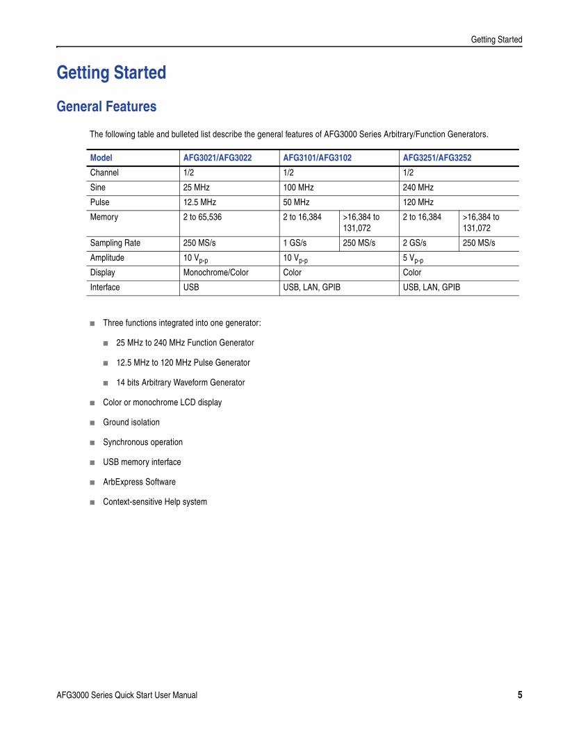
The following table and bulleted list describe the general features of AFG3000 Series Arbitrary/Function Generators.
Three functions integrated into one generator:
25 MHz to 240 MHz Function Generator
12.5 MHz to 120 MHz Pulse Generator
14 bits Arbitrary Waveform Generator
Color or monochrome LCD display
Ground isolation
Synchronous operation
USB memory interface
ArbExpress Software
Context-sensitive Help system
Model AFG3021/AFG3022 AFG3101/AFG3102 AFG3251/AFG3252
Channel 1/2 1/2 1/2
Sine 25 MHz 100 MHz 240 MHz
Pulse 12.5 MHz 50 MHz 120 MHz
Memory 2 to 65,536 2 to 16,384 >16,384 to 131,072
2 to 16,384 >16,384 to 131,072
Sampling Rate 250 MS/s 1 GS/s 250 MS/s 2 GS/s 250 MS/s
Amplitude 10 Vp-p 10 Vp-p 5 Vp-p
Display Monochrome/Color Color Color
Interface USB USB, LAN, GPIB USB, LAN, GPIB
AFG3000 Series Quick Start User Manual 5
Getting Started
Before Installation
Inspect the arbitrary/function generator carton for external damage. If the carton is damaged, notify the carrier.
Remove the arbitrary/function generator from its package and check that it has not been damaged in transit. Verify that the carton contains the instrument and its standard accessories. Refer to Standard Accessories on page 7.
Operating Requirements
Environmental
Power Supply Requirements
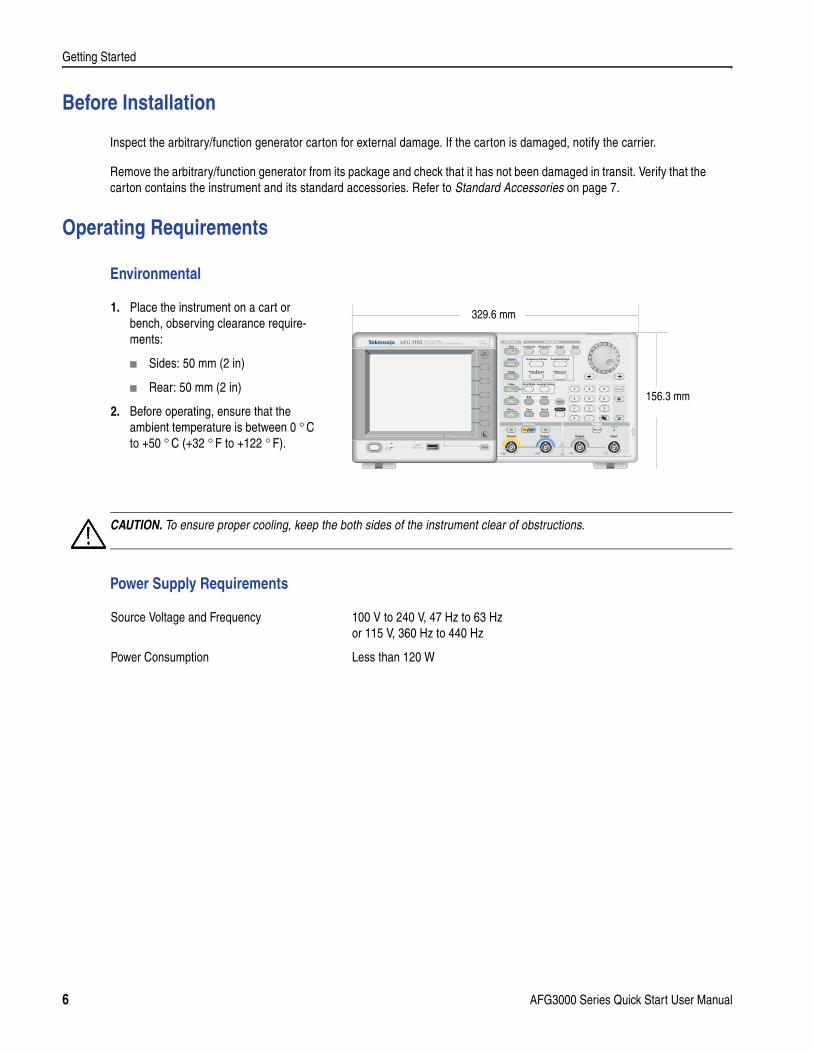
1. Place the instrument on a cart or bench, observing clearance require-ments:
Sides: 50 mm (2 in)
Rear: 50 mm (2 in)
2. Before operating, ensure that the ambient temperature is between 0 ° C to +50 ° C (+32 ° F to +122 ° F).
CAUTION. To ensure proper cooling, keep the both sides of the instrument clear of obstructions.
Output
USBMemory
USBMemory
AFG 3102 1GS/s100MHz
DUAL CHANNELARBITRARY/FUNCTION GENERATOR
InputOutput Output
Channel TriggerTrigger
View
Ch2Ch1
Run ModeFunction
Sine
Leading/TrailingDuty/Width
Sweep Burst
Edit Utility
Save RecallMore...
Arb
Pulse
Ramp
Square
Continuous Modulation
Default
Help
Offset/Low
Frequency/Period Amplitude/High
Phase Delay
156.3 mm
329.6 mm
Source Voltage and Frequency 100 V to 240 V, 47 Hz to 63 Hz or 115 V, 360 Hz to 440 Hz
Power Consumption Less than 120 W
6 AFG3000 Series Quick Start User Manual
Getting Started
Standard Accessories
Unpack the instrument and check that you received all items listed as Standard Accessories. Check the Tektronix web site (www.tektronix.com) for the most current information.
Accessory Tektronixpart number
The AFG3000 Series Arbitrary/Function Generators Quick Start User Manual
English (Option L0) 071-1631-xx
French (Option L1)1 071-1632-xx
Italian (Option L2) 071-1669-xx
German (Option L3) 1 071-1633-xx
Spanish (Option L4) 071-1670-xx
Japanese (Option L5) 1 071-1634-xx
Simple Chinese (Option L7) 1 071-1635-xx
Standard Chinese (Option L8) 1 071-1636-xx
Korean (Option L9) 1 071-1637-xx
Russian (Option L10) 071-1638-xx
No printed manual (Option L99) – – –
AFG3000 Series Product CD 063-3828-xx
ArbExpress (Application Software for Tektronix Arbitrary/ Function Generators) Software CD
063-3763-xx
The AFG3000 Series Arbitrary/Function Generators Refer-ence Manual (a PDF file on the AFG3000 Series Product CD)
071-1639-xx
The AFG3000 Series Arbitrary/Function Generators Service Manual (a PDF file on the Product CD)
071-1640-xx
Power Cord North America (Option A0) 161-0066-00
Universal Euro (Option A1) 161-0066-09
United Kingdom (Option A2) 161-0066-10
Australia (Option A3) 161-0066-13
Switzerland (Option A5) 161-0154-00
Japan (Option A6) 161-0298-00
China (Option A10) 161-0304-00
No power cord or AC adapter (Option A99)
– – –
1. These manuals contain a language overlay for the front panel controls.
AFG3000 Series Quick Start User Manual 7
Getting Started
Powering the Instrument On and Off
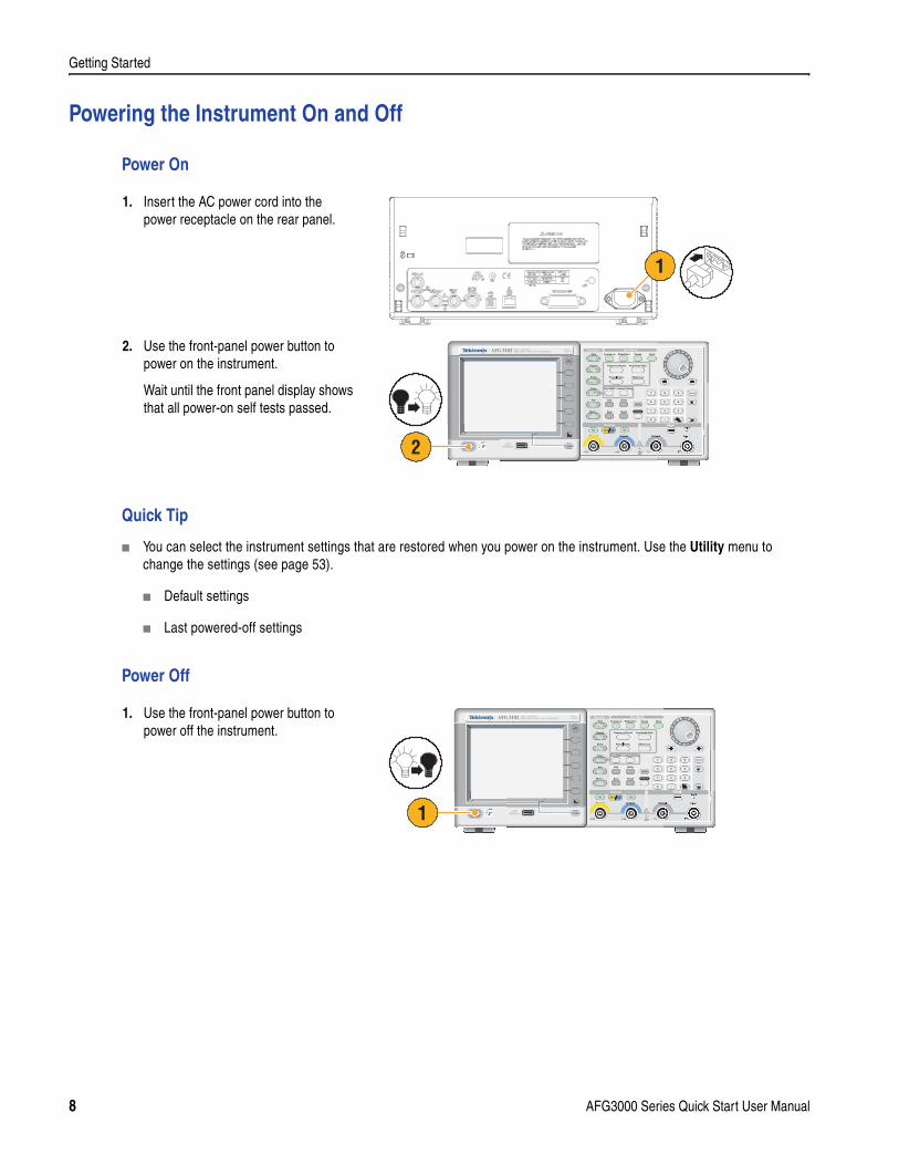
Power On
Quick Tip
You can select the instrument settings that are restored when you power on the instrument. Use the Utility menu to change the settings (see page 53).
Default settings
Last powered-off settings
Power Off
1. Insert the AC power cord into the power receptacle on the rear panel.
2. Use the front-panel power button to power on the instrument.
Wait until the front panel display shows that all power-on self tests passed.
1. Use the front-panel power button to power off the instrument.
120VA
1
Output
USBMemory
USBMemory
AFG 3102 1GS/s100MHz
DUAL CHANNELARBITRARY/FUNCTION GENERATOR
InputOutput Output
Channel TriggerTrigger
View
Ch2Ch1
Run ModeFunction
Sine
Leading/TrailingDuty/Width
Sweep Burst
Edit Utility
Save RecallMore...
Arb
Pulse
Ramp
Square
Continuous Modulation
Default
Help
Offset/Low
Frequency/Period Amplitude/High
Phase Delay
2
Output
USBMemory
USBMemory
AFG 3102 1GS/s100MHz
DUAL CHANNELARBITRARY/FUNCTION GENERATOR
InputOutput Output
Channel TriggerTrigger
View
Ch2Ch1
Run ModeFunction
Sine
Leading/TrailingDuty/Width
Sweep Burst
Edit Utility
Save RecallMore...
Arb
Pulse
Ramp
Square
Continuous Modulation
Default
Help
Offset/Low
Frequency/Period Amplitude/High
Phase Delay
1
8 AFG3000 Series Quick Start User Manual
Getting Started
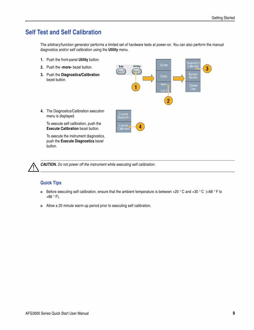
Self Test and Self Calibration
The arbitrary/function generator performs a limited set of hardware tests at power-on. You can also perform the manual diagnostics and/or self calibration using the Utility menu.
Quick Tips
Before executing self calibration, ensure that the ambient temperature is between +20 ° C and +30 ° C (+68 ° F to +86 ° F).
Allow a 20 minute warm-up period prior to executing self calibration.
1. Push the front-panel Utility button.
2. Push the -more- bezel button.
3. Push the Diagnostics/Calibration bezel button.
4. The Diagnostics/Calibration execution menu is displayed.
To execute self calibration, push the Execute Calibration bezel button.
To execute the instrument diagnostics, push the Execute Diagnostics bezel button.
2
1
3
4
CAUTION. Do not power off the instrument while executing self calibration.
AFG3000 Series Quick Start User Manual 9
Getting Started
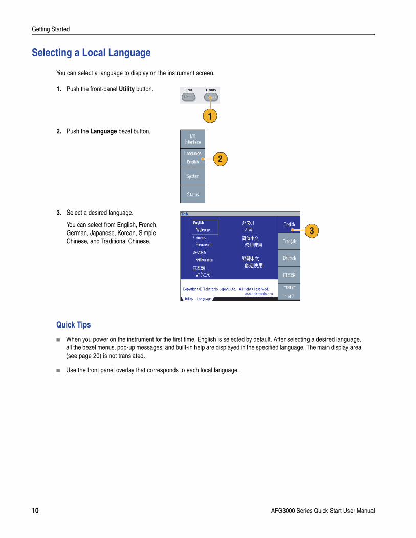
Selecting a Local Language
You can select a language to display on the instrument screen.
Quick Tips
When you power on the instrument for the first time, English is selected by default. After selecting a desired language, all the bezel menus, pop-up messages, and built-in help are displayed in the specified language. The main display area (see page 20) is not translated.
Use the front panel overlay that corresponds to each local language.
1. Push the front-panel Utility button.
2. Push the Language bezel button.
3. Select a desired language.
You can select from English, French, German, Japanese, Korean, Simple Chinese, and Traditional Chinese.
1
2
3
10 AFG3000 Series Quick Start User Manual
Getting Started
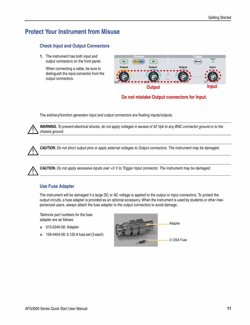
Protect Your Instrument from Misuse
Check Input and Output Connectors
The arbitrary/function generator input and output connectors are floating inputs/outputs.
Use Fuse Adapter
The instrument will be damaged if a large DC or AC voltage is applied to the output or input connectors. To protect the output circuits, a fuse adapter is provided as an optional accessory. When the instrument is used by students or other inex-perienced users, always attach the fuse adapter to the output connectors to avoid damage.
1. The instrument has both input and output connectors on the front panel.
When connecting a cable, be sure to distinguish the input connector from the output connectors.
Do not mistake Output connectors for Input.
Output Input
WARNING. To prevent electrical shocks, do not apply voltages in excess of 42 Vpk to any BNC connector ground or to the chassis ground.
CAUTION. Do not short output pins or apply external voltages to Output connectors. The instrument may be damaged.
CAUTION. Do not apply excessive inputs over +5 V to Trigger Input connector. The instrument may be damaged.
Tektronix part numbers for the fuse adapter are as follows:
013-0345-00: Adapter
159-0454-00: 0.125 A fuse set (3 each)
Adapter
0.125A Fuse
AFG3000 Series Quick Start User Manual 11
Getting Started
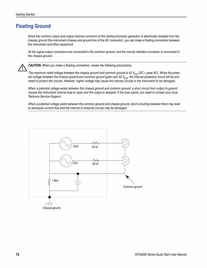
Floating Ground
Since the common (input and output channel common) of the arbitrary/function generator is electrically isolated from the chassis ground (the instrument chassis and ground line of the AC connector), you can make a floating connection between the instrument and other equipment.
All the signal output connectors are connected to the common ground, and the remote interface connector is connected to the chassis ground.
CAUTION. When you make a floating connection, review the following precautions:
The maximum rated voltage between the chassis ground and common ground is 42 Vp-p (DC + peak AC). When the poten-tial voltage between the chassis ground and common ground goes over 42 Vp-p, the internal protective circuit will be acti-vated to protect the circuits. However, higher voltage may cause the internal circuits in the instrument to be damaged.
When a potential voltage exists between the chassis ground and common ground, a short circuit from output to ground causes the instrument internal fuse to open and the output is stopped. If the fuse opens, you need to contact your local Tektronix Service Support.
When a potential voltage exists between the common ground and chassis ground, short-circuiting between them may lead to excessive current flow and the internal or external circuits may be damaged.
Chassis ground
Common ground
CH2
CH1
50 Ω
50 Ω
1 MΩ
12 AFG3000 Series Quick Start User Manual
Getting Started
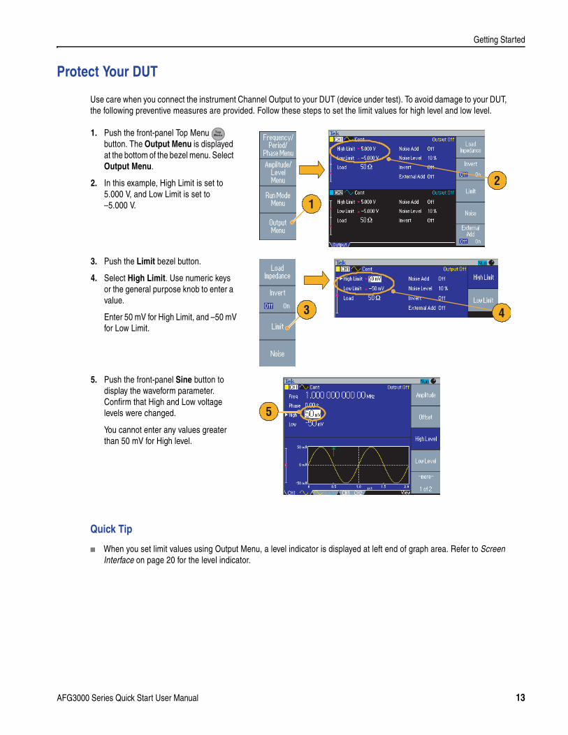
Protect Your DUT
Use care when you connect the instrument Channel Output to your DUT (device under test). To avoid damage to your DUT, the following preventive measures are provided. Follow these steps to set the limit values for high level and low level.
Quick Tip
When you set limit values using Output Menu, a level indicator is displayed at left end of graph area. Refer to Screen Interface on page 20 for the level indicator.
1. Push the front-panel Top Menu button. The Output Menu is displayed at the bottom of the bezel menu. Select Output Menu.
2. In this example, High Limit is set to 5.000 V, and Low Limit is set to –5.000 V.
3. Push the Limit bezel button.
4. Select High Limit. Use numeric keys or the general purpose knob to enter a value.
Enter 50 mV for High Limit, and –50 mV for Low Limit.
5. Push the front-panel Sine button to display the waveform parameter. Confirm that High and Low voltage levels were changed.
You cannot enter any values greater than 50 mV for High level.
1
2
3 4
5
AFG3000 Series Quick Start User Manual 13
Getting Started
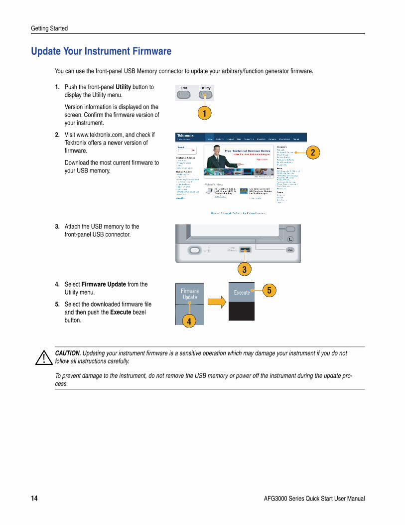
Update Your Instrument Firmware
You can use the front-panel USB Memory connector to update your arbitrary/function generator firmware.
1. Push the front-panel Utility button to display the Utility menu.
Version information is displayed on the screen. Confirm the firmware version of your instrument.
2. Visit www.tektronix.com, and check if Tektronix offers a newer version of firmware.
Download the most current firmware to your USB memory.
3. Attach the USB memory to the front-panel USB connector.
4. Select Firmware Update from the Utility menu.
5. Select the downloaded firmware file and then push the Execute bezel button.
1
2
3
5
4
CAUTION. Updating your instrument firmware is a sensitive operation which may damage your instrument if you do not follow all instructions carefully.
To prevent damage to the instrument, do not remove the USB memory or power off the instrument during the update pro-cess.
14 AFG3000 Series Quick Start User Manual
Getting Started
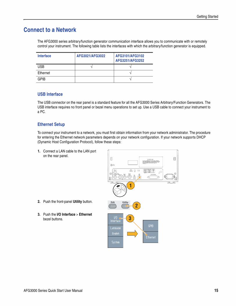
Connect to a Network
The AFG3000 series arbitrary/function generator communication interface allows you to communicate with or remotely control your instrument. The following table lists the interfaces with which the arbitrary/function generator is equipped.
USB Interface
The USB connector on the rear panel is a standard feature for all the AFG3000 Series Arbitrary/Function Generators. The USB interface requires no front panel or bezel menu operations to set up. Use a USB cable to connect your instrument to a PC.
Ethernet Setup
To connect your instrument to a network, you must first obtain information from your network administrator. The procedure for entering the Ethernet network parameters depends on your network configuration. If your network supports DHCP (Dynamic Host Configuration Protocol), follow these steps:
Interface AFG3021/AFG3022 AFG3101/AFG3102AFG3251/AFG3252
USB √ √Ethernet √GPIB √
1. Connect a LAN cable to the LAN port on the rear panel.
2. Push the front-panel Utility button.
3. Push the I/O Interface > Ethernet bezel buttons.
120VA
1
2
3
AFG3000 Series Quick Start User Manual 15
Getting Started
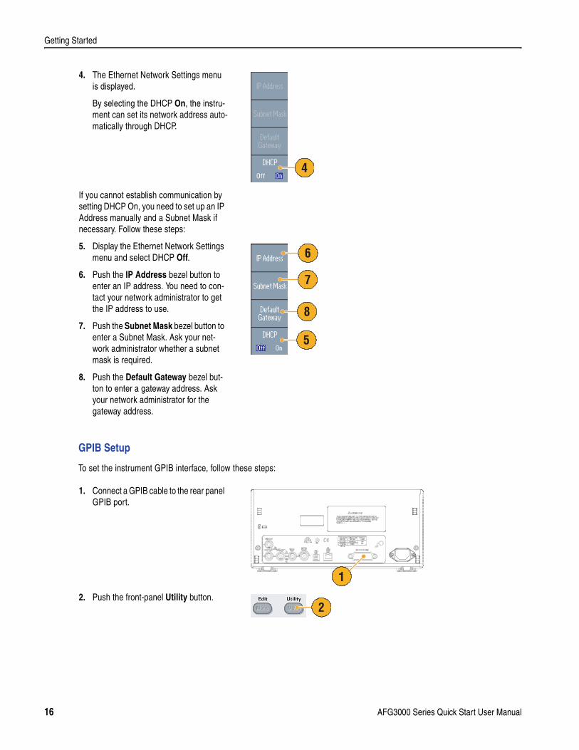
GPIB Setup
To set the instrument GPIB interface, follow these steps:
4. The Ethernet Network Settings menu is displayed.
By selecting the DHCP On, the instru-ment can set its network address auto-matically through DHCP.
If you cannot establish communication by setting DHCP On, you need to set up an IP Address manually and a Subnet Mask if necessary. Follow these steps:
5. Display the Ethernet Network Settings menu and select DHCP Off.
6. Push the IP Address bezel button to enter an IP address. You need to con-tact your network administrator to get the IP address to use.
7. Push the Subnet Mask bezel button to enter a Subnet Mask. Ask your net-work administrator whether a subnet mask is required.
8. Push the Default Gateway bezel but-ton to enter a gateway address. Ask your network administrator for the gateway address.
1. Connect a GPIB cable to the rear panel GPIB port.
2. Push the front-panel Utility button.
4
6
8
7
5
120VA
1
2
16 AFG3000 Series Quick Start User Manual
Getting Started
Quick Tip
Refer to the AFG3000 Series Arbitrary/Function Generators Reference Manual for information on remote control commands.
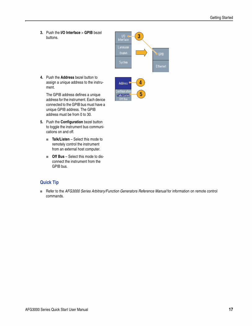
3. Push the I/O Interface > GPIB bezel buttons.
4. Push the Address bezel button to assign a unique address to the instru-ment.
The GPIB address defines a unique address for the instrument. Each device connected to the GPIB bus must have a unique GPIB address. The GPIB address must be from 0 to 30.
5. Push the Configuration bezel button to toggle the instrument bus communi-cations on and off.
Talk/Listen – Select this mode to remotely control the instrument from an external host computer.
Off Bus – Select this mode to dis-connect the instrument from the GPIB bus.
3
4
5
AFG3000 Series Quick Start User Manual 17

Getting Started
18 AFG3000 Series Quick Start User Manual
Getting Acquainted with Your Instrument
Getting Acquainted with Your Instrument
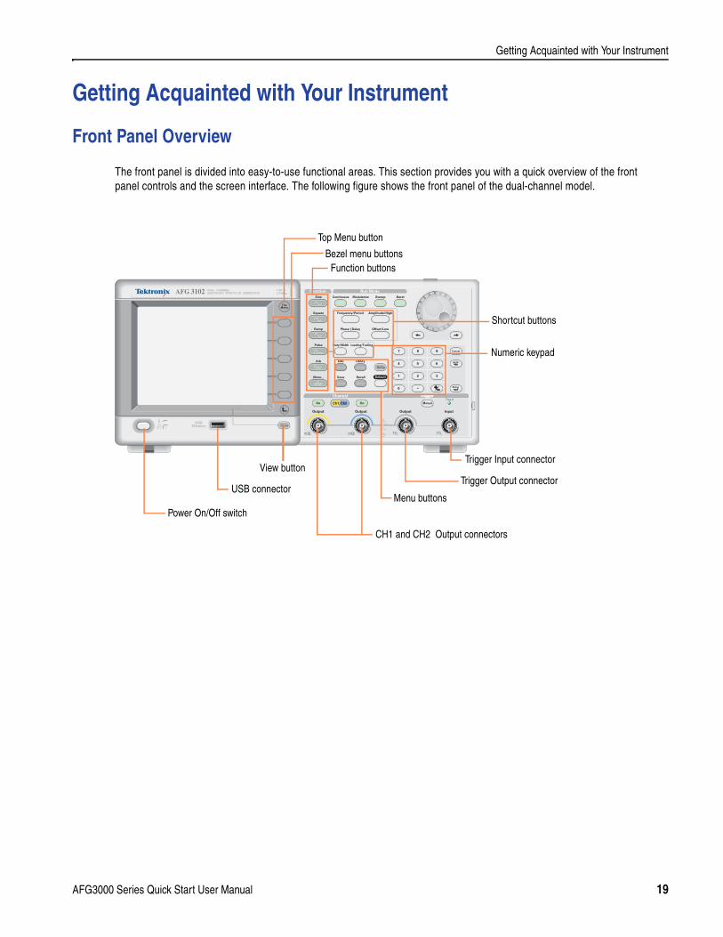
Front Panel Overview
The front panel is divided into easy-to-use functional areas. This section provides you with a quick overview of the front panel controls and the screen interface. The following figure shows the front panel of the dual-channel model.
Output
USBMemory
USBMemory
AFG 3102 1GS/s100MHz
DUAL CHANNELARBITRARY/FUNCTION GENERATOR
InputOutput Output
Channel TriggerTrigger
View
Ch2Ch1
Run ModeFunction
Sine
Leading/TrailingDuty/Width
Sweep Burst
Edit Utility
Save RecallMore...
Arb
Pulse
Ramp
Square
Continuous Modulation
Default
Help
Offset/Low
Frequency/Period Amplitude/High
Phase Delay
Numeric keypad
Power On/Off switch
Shortcut buttons
Function buttonsBezel menu buttons
Trigger Input connector
USB connector
View buttonTrigger Output connector
CH1 and CH2 Output connectors
Menu buttons
Top Menu button
AFG3000 Series Quick Start User Manual 19
Getting Acquainted with Your Instrument
Screen Interface
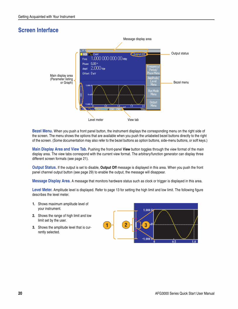
Bezel Menu. When you push a front panel button, the instrument displays the corresponding menu on the right side of the screen. The menu shows the options that are available when you push the unlabeled bezel buttons directly to the right of the screen. (Some documentation may also refer to the bezel buttons as option buttons, side-menu buttons, or soft keys.)
Main Display Area and View Tab. Pushing the front-panel View button toggles through the view format of the main display area. The view tabs correspond with the current view format. The arbitrary/function generator can display three different screen formats (see page 21).
Output Status. If the output is set to disable, Output Off message is displayed in this area. When you push the front panel channel output button (see page 29) to enable the output, the message will disappear.
Message Display Area. A message that monitors hardware status such as clock or trigger is displayed in this area.
Level Meter. Amplitude level is displayed. Refer to page 13 for setting the high limit and low limit. The following figure describes the level meter.
Bezel menu
Main display area(Parameter listing
or Graph)
View tab
Message display area
Output status
Level meter
1. Shows maximum amplitude level of your instrument.
2. Shows the range of high limit and low limit set by the user.
3. Shows the amplitude level that is cur-rently selected.
21 3
20 AFG3000 Series Quick Start User Manual
Getting Acquainted with Your Instrument
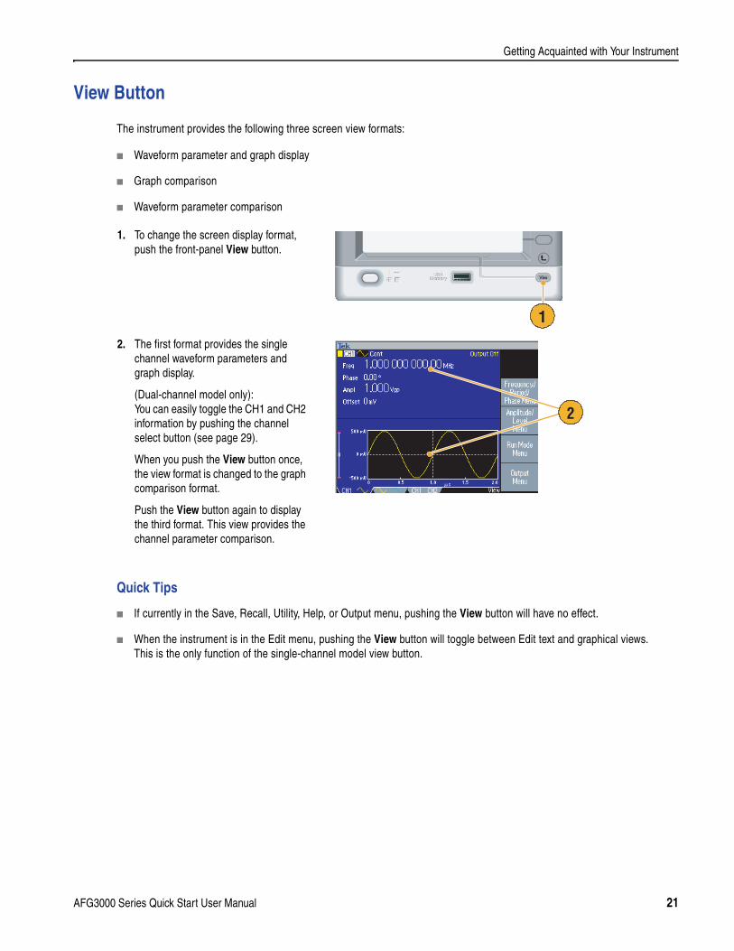
View Button
The instrument provides the following three screen view formats:
Waveform parameter and graph display
Graph comparison
Waveform parameter comparison
Quick Tips
If currently in the Save, Recall, Utility, Help, or Output menu, pushing the View button will have no effect.
When the instrument is in the Edit menu, pushing the View button will toggle between Edit text and graphical views. This is the only function of the single-channel model view button.
1. To change the screen display format, push the front-panel View button.
2. The first format provides the single channel waveform parameters and graph display.
(Dual-channel model only):You can easily toggle the CH1 and CH2 information by pushing the channel select button (see page 29).
When you push the View button once, the view format is changed to the graph comparison format.
Push the View button again to display the third format. This view provides the channel parameter comparison.
1
2
AFG3000 Series Quick Start User Manual 21
Getting Acquainted with Your Instrument
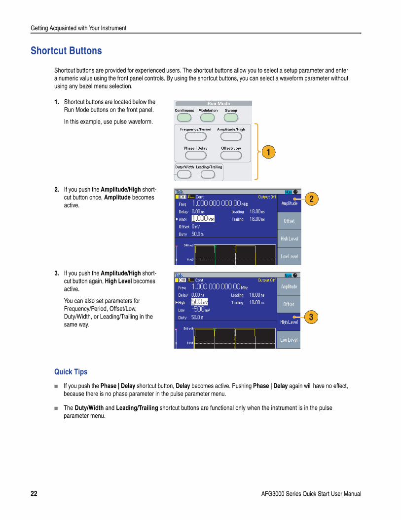
Shortcut Buttons
Shortcut buttons are provided for experienced users. The shortcut buttons allow you to select a setup parameter and enter a numeric value using the front panel controls. By using the shortcut buttons, you can select a waveform parameter without using any bezel menu selection.
Quick Tips
If you push the Phase | Delay shortcut button, Delay becomes active. Pushing Phase | Delay again will have no effect, because there is no phase parameter in the pulse parameter menu.
The Duty/Width and Leading/Trailing shortcut buttons are functional only when the instrument is in the pulse parameter menu.
1. Shortcut buttons are located below the Run Mode buttons on the front panel.
In this example, use pulse waveform.
2. If you push the Amplitude/High short-cut button once, Amplitude becomes active.
3. If you push the Amplitude/High short-cut button again, High Level becomes active.
You can also set parameters for Frequency/Period, Offset/Low, Duty/Width, or Leading/Trailing in the same way.
1
2
3
22 AFG3000 Series Quick Start User Manual

Getting Acquainted with Your Instrument
Default Setup
When you want to restore the instrument settings to the default values, use the front-panel Default button.
1. Push the front-panel Default button.
2. A confirmation pop-up message appears on the screen.
Push OK to recall the default settings.
Push Cancel to cancel the recall.
3. If you select OK, the instrument dis-plays a 1 MHz frequency, 1 Vp-p ampli-tude sine waveform as the default setup.
1
2
3
AFG3000 Series Quick Start User Manual 23
Getting Acquainted with Your Instrument
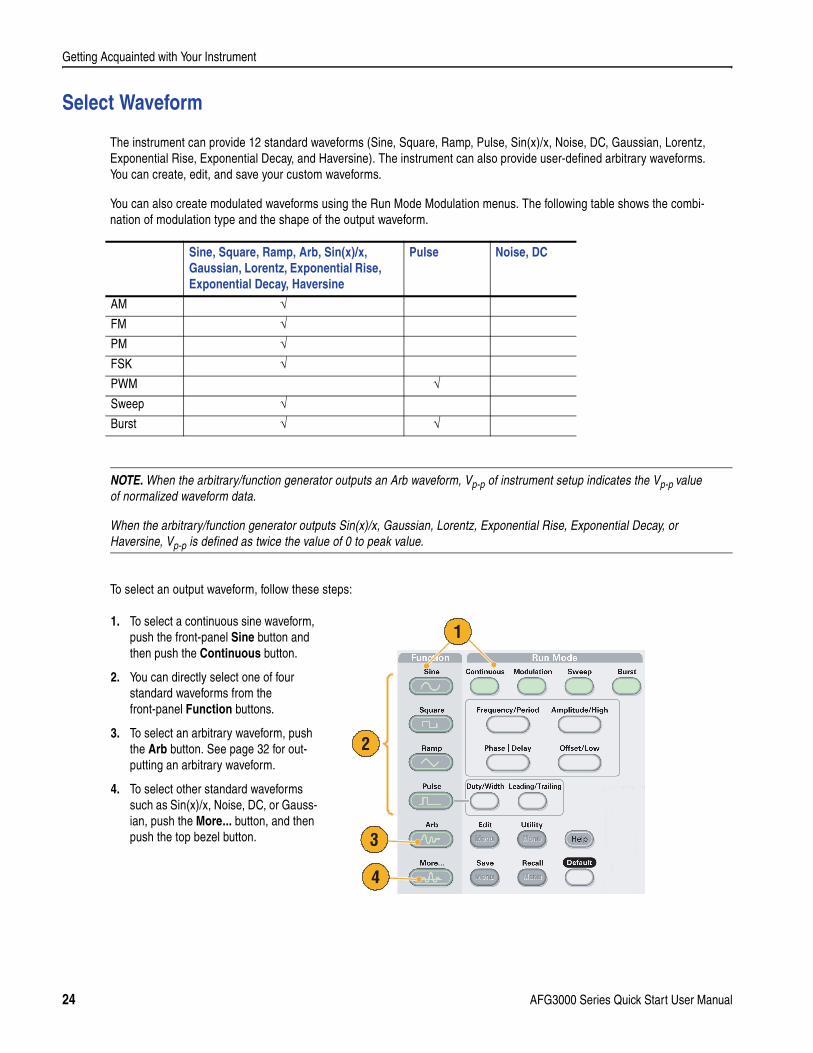
Select Waveform
The instrument can provide 12 standard waveforms (Sine, Square, Ramp, Pulse, Sin(x)/x, Noise, DC, Gaussian, Lorentz, Exponential Rise, Exponential Decay, and Haversine). The instrument can also provide user-defined arbitrary waveforms. You can create, edit, and save your custom waveforms.
You can also create modulated waveforms using the Run Mode Modulation menus. The following table shows the combi-nation of modulation type and the shape of the output waveform.
To select an output waveform, follow these steps:
Sine, Square, Ramp, Arb, Sin(x)/x, Gaussian, Lorentz, Exponential Rise, Exponential Decay, Haversine
Pulse Noise, DC
AM √FM √PM √FSK √PWM √Sweep √Burst √ √
NOTE. When the arbitrary/function generator outputs an Arb waveform, Vp-p of instrument setup indicates the Vp-p value of normalized waveform data.
When the arbitrary/function generator outputs Sin(x)/x, Gaussian, Lorentz, Exponential Rise, Exponential Decay, or Haversine, Vp-p is defined as twice the value of 0 to peak value.
1. To select a continuous sine waveform, push the front-panel Sine button and then push the Continuous button.
2. You can directly select one of four standard waveforms from the front-panel Function buttons.
3. To select an arbitrary waveform, push the Arb button. See page 32 for out-putting an arbitrary waveform.
4. To select other standard waveforms such as Sin(x)/x, Noise, DC, or Gauss-ian, push the More... button, and then push the top bezel button.
1
2
4
3
24 AFG3000 Series Quick Start User Manual
Getting Acquainted with Your Instrument
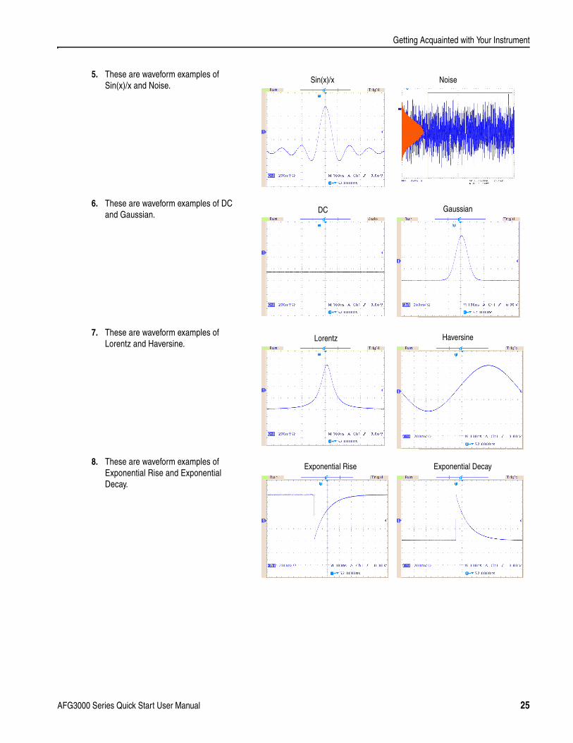
5. These are waveform examples of Sin(x)/x and Noise.
6. These are waveform examples of DC and Gaussian.
7. These are waveform examples of Lorentz and Haversine.
8. These are waveform examples of Exponential Rise and Exponential Decay.
Sin(x)/x Noise
GaussianDC
HaversineLorentz
Exponential DecayExponential Rise
AFG3000 Series Quick Start User Manual 25
Getting Acquainted with Your Instrument
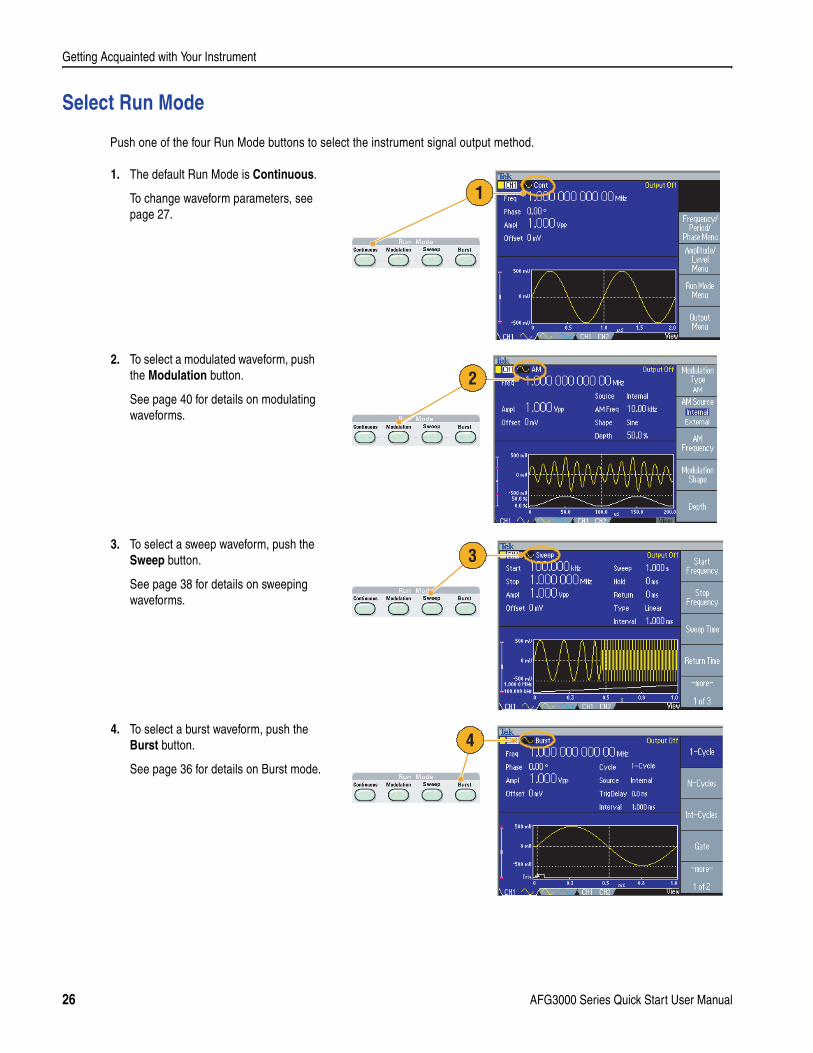
Select Run Mode
Push one of the four Run Mode buttons to select the instrument signal output method.
1. The default Run Mode is Continuous.
To change waveform parameters, see page 27.
2. To select a modulated waveform, push the Modulation button.
See page 40 for details on modulating waveforms.
3. To select a sweep waveform, push the Sweep button.
See page 38 for details on sweeping waveforms.
4. To select a burst waveform, push the Burst button.
See page 36 for details on Burst mode.
1
2
3
4
26 AFG3000 Series Quick Start User Manual
Getting Acquainted with Your Instrument
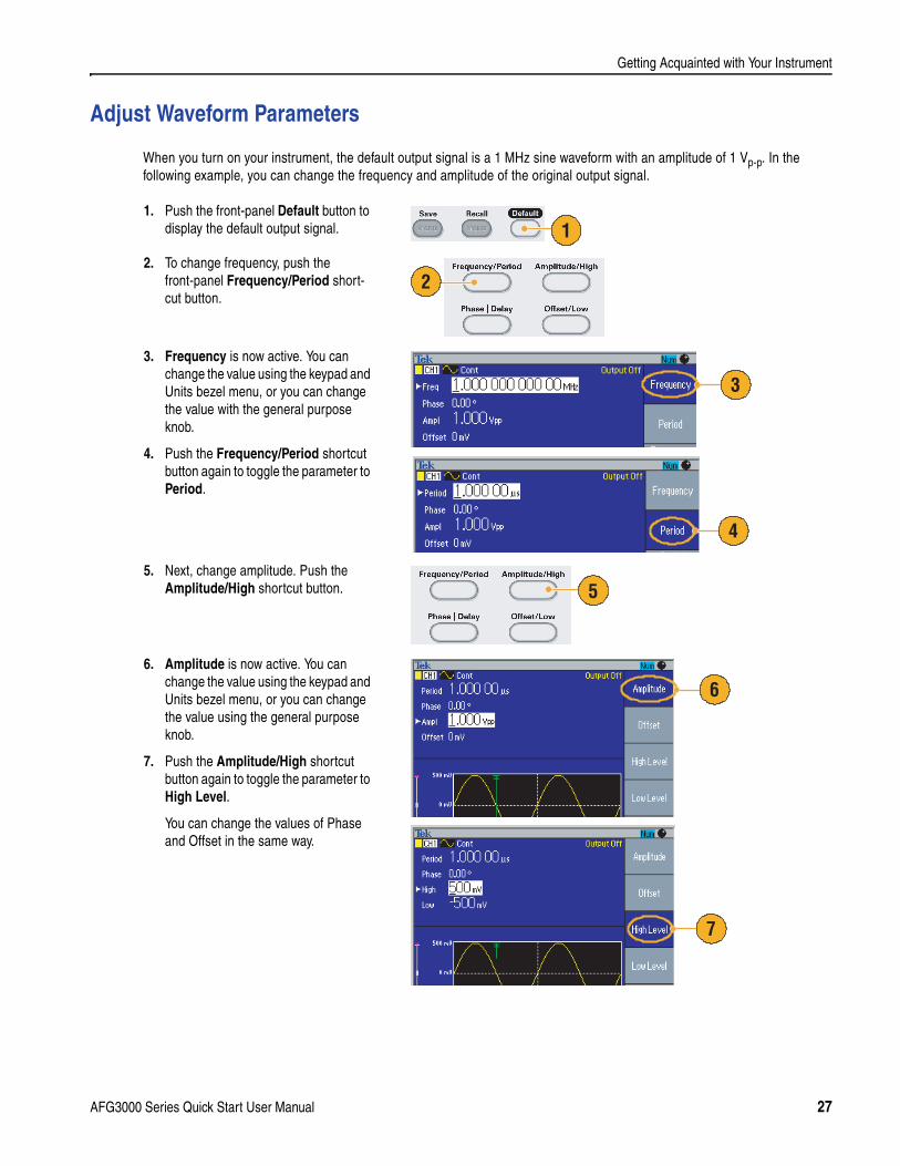
Adjust Waveform Parameters
When you turn on your instrument, the default output signal is a 1 MHz sine waveform with an amplitude of 1 Vp-p. In the following example, you can change the frequency and amplitude of the original output signal.
1. Push the front-panel Default button to display the default output signal.
2. To change frequency, push the front-panel Frequency/Period short-cut button.
3. Frequency is now active. You can change the value using the keypad and Units bezel menu, or you can change the value with the general purpose knob.
4. Push the Frequency/Period shortcut button again to toggle the parameter to Period.
5. Next, change amplitude. Push the Amplitude/High shortcut button.
6. Amplitude is now active. You can change the value using the keypad and Units bezel menu, or you can change the value using the general purpose knob.
7. Push the Amplitude/High shortcut button again to toggle the parameter to High Level.
You can change the values of Phase and Offset in the same way.
1
2
3
4
5
6
7
AFG3000 Series Quick Start User Manual 27
Getting Acquainted with Your Instrument
Quick Tip
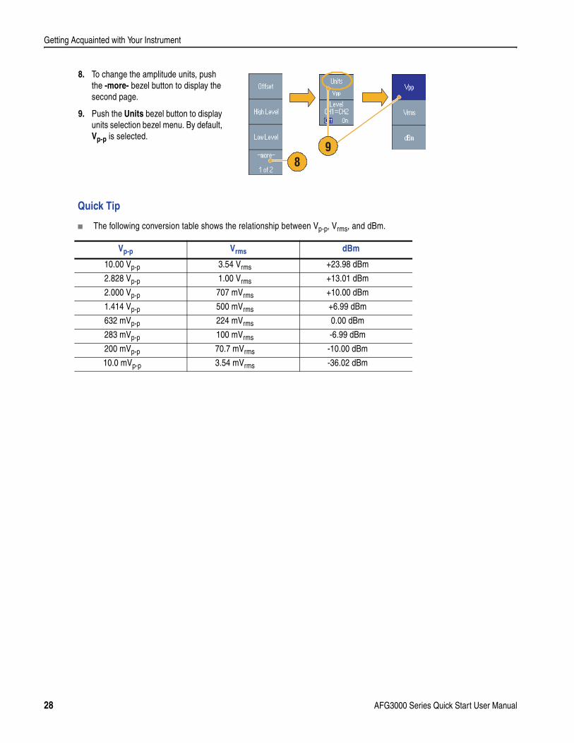
The following conversion table shows the relationship between Vp-p, Vrms, and dBm.
8. To change the amplitude units, push the -more- bezel button to display the second page.
9. Push the Units bezel button to display units selection bezel menu. By default, Vp-p is selected.
Vp-p Vrms dBm
10.00 Vp-p 3.54 Vrms +23.98 dBm
2.828 Vp-p 1.00 Vrms +13.01 dBm
2.000 Vp-p 707 mVrms +10.00 dBm
1.414 Vp-p 500 mVrms +6.99 dBm
632 mVp-p 224 mVrms 0.00 dBm
283 mVp-p 100 mVrms -6.99 dBm
200 mVp-p 70.7 mVrms -10.00 dBm
10.0 mVp-p 3.54 mVrms -36.02 dBm
89
28 AFG3000 Series Quick Start User Manual
Getting Acquainted with Your Instrument
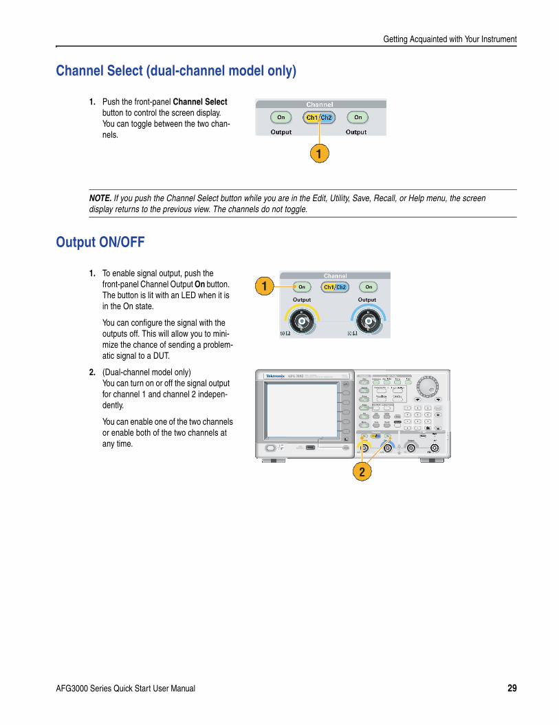
Channel Select (dual-channel model only)
Output ON/OFF
1. Push the front-panel Channel Select button to control the screen display. You can toggle between the two chan-nels.
NOTE. If you push the Channel Select button while you are in the Edit, Utility, Save, Recall, or Help menu, the screen display returns to the previous view. The channels do not toggle.
1. To enable signal output, push the front-panel Channel Output On button. The button is lit with an LED when it is in the On state.
You can configure the signal with the outputs off. This will allow you to mini-mize the chance of sending a problem-atic signal to a DUT.
2. (Dual-channel model only) You can turn on or off the signal output for channel 1 and channel 2 indepen-dently.
You can enable one of the two channels or enable both of the two channels at any time.
1
1
Output
USBMemory
USBMemory
AFG 3102 1GS/s100MHz
DUAL CHANNELARBITRARY/FUNCTION GENERATOR
InputOutput Output
Channel TriggerTrigger
View
Ch2Ch1
Run ModeFunction
Sine
Leading/TrailingDuty/Width
Sweep Burst
Edit Utility
Save RecallMore...
Arb
Pulse
Ramp
Square
Continuous Modulation
Default
Help
Offset/Low
Frequency/Period Amplitude/High
Phase Delay
2
AFG3000 Series Quick Start User Manual 29
Getting Acquainted with Your Instrument
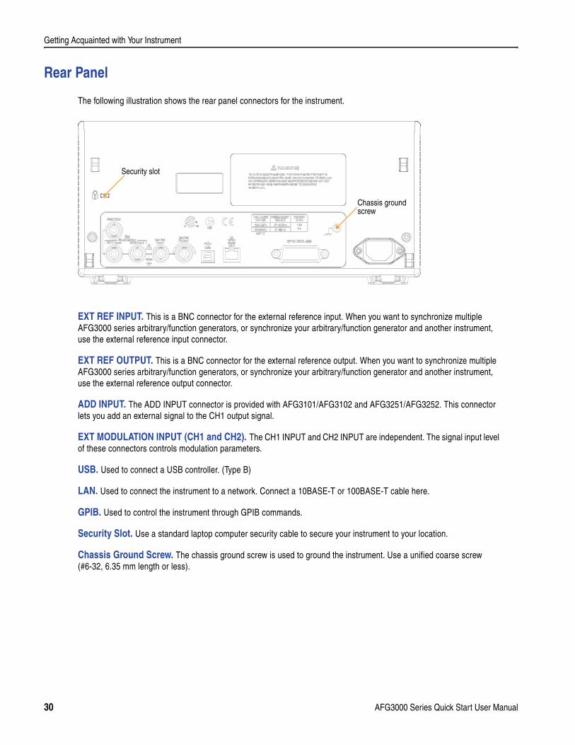
Rear Panel
The following illustration shows the rear panel connectors for the instrument.
EXT REF INPUT. This is a BNC connector for the external reference input. When you want to synchronize multiple AFG3000 series arbitrary/function generators, or synchronize your arbitrary/function generator and another instrument, use the external reference input connector.
EXT REF OUTPUT. This is a BNC connector for the external reference output. When you want to synchronize multiple AFG3000 series arbitrary/function generators, or synchronize your arbitrary/function generator and another instrument, use the external reference output connector.
ADD INPUT. The ADD INPUT connector is provided with AFG3101/AFG3102 and AFG3251/AFG3252. This connector lets you add an external signal to the CH1 output signal.
EXT MODULATION INPUT (CH1 and CH2). The CH1 INPUT and CH2 INPUT are independent. The signal input level of these connectors controls modulation parameters.
USB. Used to connect a USB controller. (Type B)
LAN. Used to connect the instrument to a network. Connect a 10BASE-T or 100BASE-T cable here.
GPIB. Used to control the instrument through GPIB commands.
Security Slot. Use a standard laptop computer security cable to secure your instrument to your location.
Chassis Ground Screw. The chassis ground screw is used to ground the instrument. Use a unified coarse screw (#6-32, 6.35 mm length or less).
120VA
Chassis groundscrew
Security slot
30 AFG3000 Series Quick Start User Manual
Operating Basics
Operating Basics
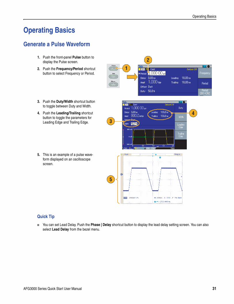
Generate a Pulse Waveform
Quick Tip
You can set Lead Delay. Push the Phase | Delay shortcut button to display the lead delay setting screen. You can also select Lead Delay from the bezel menu.
1. Push the front-panel Pulse button to display the Pulse screen.
2. Push the Frequency/Period shortcut button to select Frequency or Period.
3. Push the Duty/Width shortcut button to toggle between Duty and Width.
4. Push the Leading/Trailing shortcut button to toggle the parameters for Leading Edge and Trailing Edge.
5. This is an example of a pulse wave-form displayed on an oscilloscope screen.
1
2
3
4
5
AFG3000 Series Quick Start User Manual 31
Operating Basics
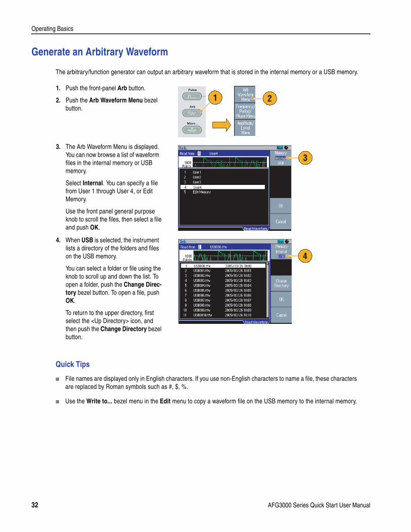
Generate an Arbitrary Waveform
The arbitrary/function generator can output an arbitrary waveform that is stored in the internal memory or a USB memory.
Quick Tips
File names are displayed only in English characters. If you use non-English characters to name a file, these characters are replaced by Roman symbols such as #, $, %.
Use the Write to... bezel menu in the Edit menu to copy a waveform file on the USB memory to the internal memory.
1. Push the front-panel Arb button.
2. Push the Arb Waveform Menu bezel button.
3. The Arb Waveform Menu is displayed. You can now browse a list of waveform files in the internal memory or USB memory.
Select Internal. You can specify a file from User 1 through User 4, or Edit Memory.
Use the front panel general purpose knob to scroll the files, then select a file and push OK.
4. When USB is selected, the instrument lists a directory of the folders and files on the USB memory.
You can select a folder or file using the knob to scroll up and down the list. To open a folder, push the Change Direc-tory bezel button. To open a file, push OK.
To return to the upper directory, first select the <Up Directory> icon, and then push the Change Directory bezel button.
1 2
3
4
32 AFG3000 Series Quick Start User Manual
Operating Basics
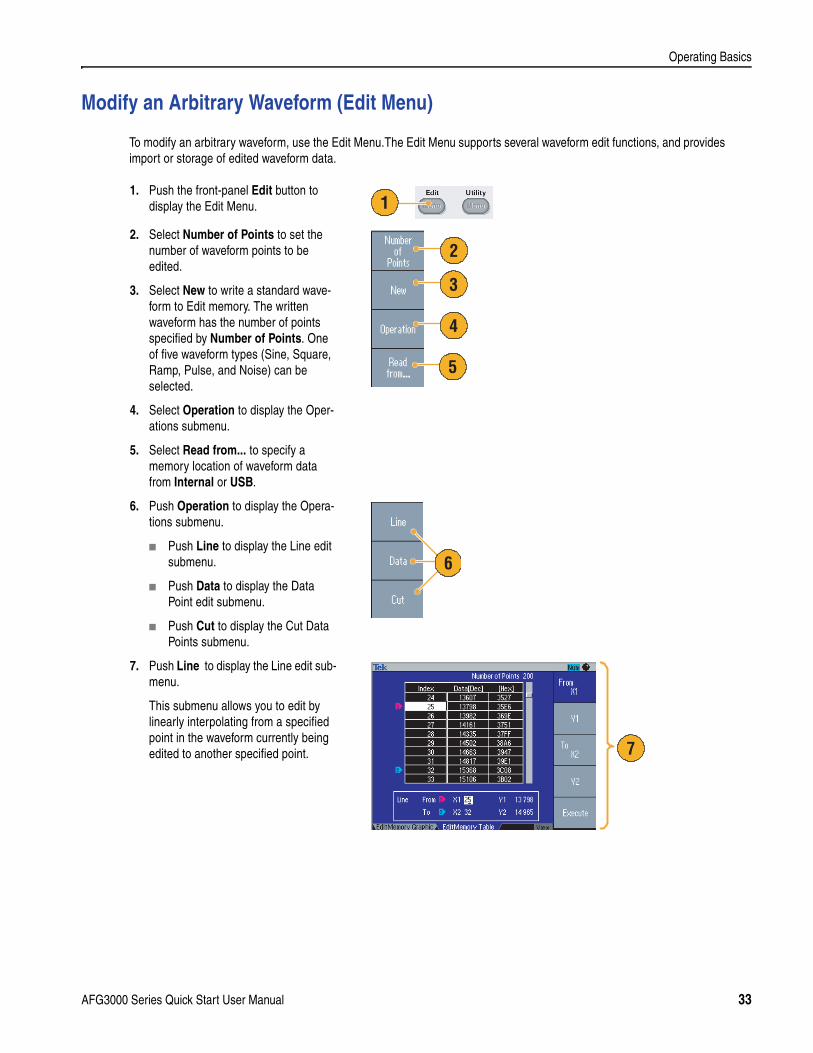
Modify an Arbitrary Waveform (Edit Menu)
To modify an arbitrary waveform, use the Edit Menu.The Edit Menu supports several waveform edit functions, and provides import or storage of edited waveform data.
1. Push the front-panel Edit button to display the Edit Menu.
2. Select Number of Points to set the number of waveform points to be edited.
3. Select New to write a standard wave-form to Edit memory. The written waveform has the number of points specified by Number of Points. One of five waveform types (Sine, Square, Ramp, Pulse, and Noise) can be selected.
4. Select Operation to display the Oper-ations submenu.
5. Select Read from... to specify a memory location of waveform data from Internal or USB.
6. Push Operation to display the Opera-tions submenu.
Push Line to display the Line edit submenu.
Push Data to display the Data Point edit submenu.
Push Cut to display the Cut Data Points submenu.
7. Push Line to display the Line edit sub-menu.
This submenu allows you to edit by linearly interpolating from a specified point in the waveform currently being edited to another specified point.
1
2
3
4
5
6
7
AFG3000 Series Quick Start User Manual 33
Operating Basics
Quick Tips
If you edit an arbitrary waveform data while the instrument generates a waveform from Edit Memory, the edited data will be automatically reflected to the generated waveform.
Push the front-panel View button in the Edit Menu to toggle between edit texts and graphical views.
Push the -more- bezel button in the Write to... submenu to display the Lock/Unlock and the Erase menu.
The Lock/Unlock function allows you to lock the file against accidental overwrite.
Refer to the AFG3000 Series Arbitrary/Function Generators Reference Manual for more information on the Edit Menu.
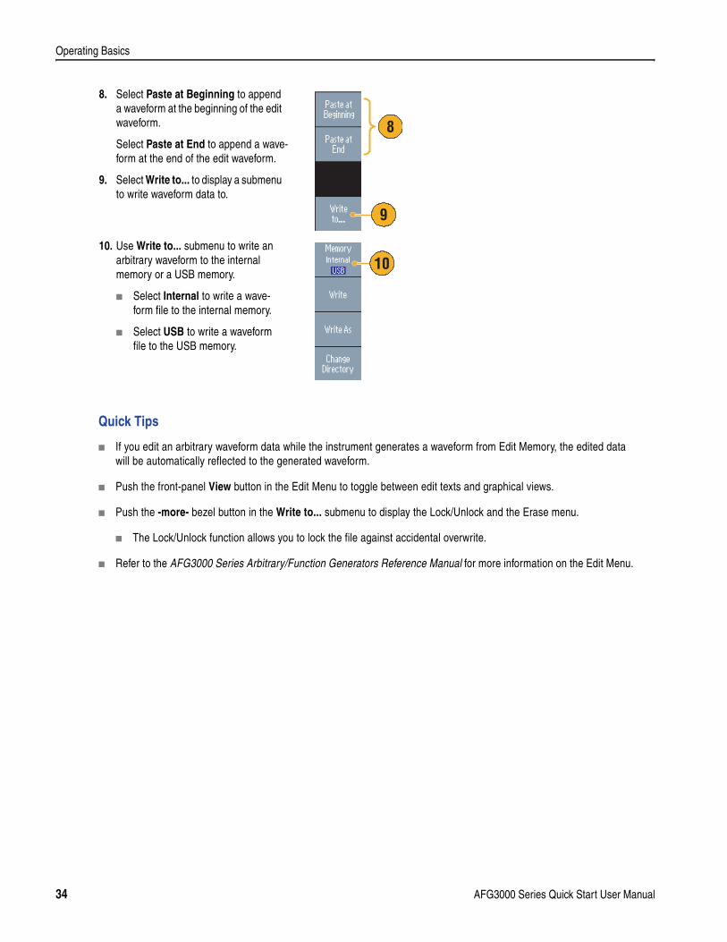
8. Select Paste at Beginning to append a waveform at the beginning of the edit waveform.
Select Paste at End to append a wave-form at the end of the edit waveform.
9. Select Write to... to display a submenu to write waveform data to.
10. Use Write to... submenu to write an arbitrary waveform to the internal memory or a USB memory.
Select Internal to write a wave-form file to the internal memory.
Select USB to write a waveform file to the USB memory.
9
8
10
34 AFG3000 Series Quick Start User Manual
Operating Basics
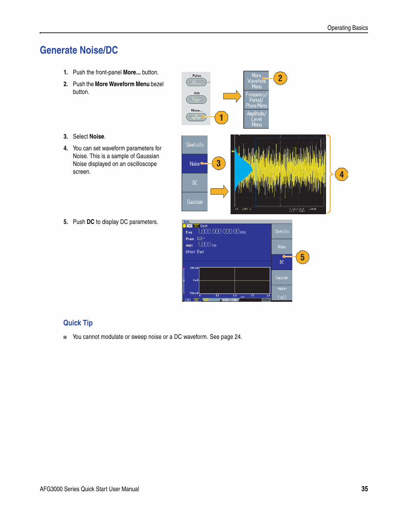
Generate Noise/DC
Quick Tip
You cannot modulate or sweep noise or a DC waveform. See page 24.
1. Push the front-panel More... button.
2. Push the More Waveform Menu bezel button.
3. Select Noise.
4. You can set waveform parameters for Noise. This is a sample of Gaussian Noise displayed on an oscilloscope screen.
5. Push DC to display DC parameters.
1
2
43
5
AFG3000 Series Quick Start User Manual 35
Operating Basics
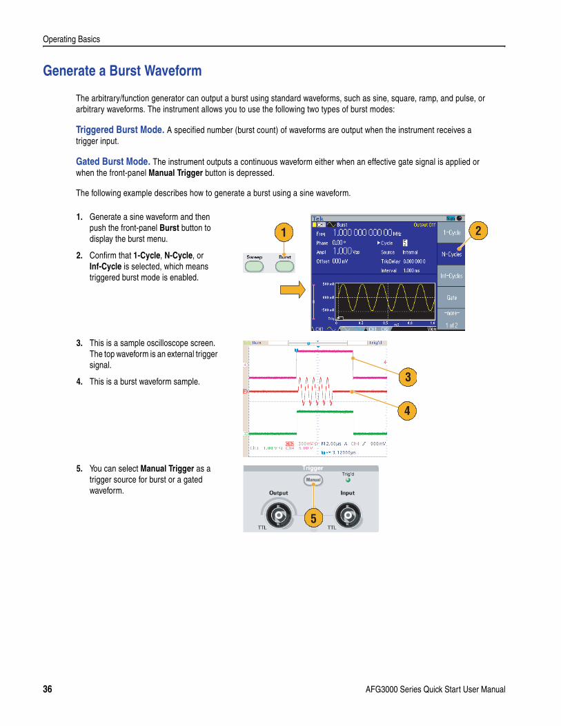
Generate a Burst Waveform
The arbitrary/function generator can output a burst using standard waveforms, such as sine, square, ramp, and pulse, or arbitrary waveforms. The instrument allows you to use the following two types of burst modes:
Triggered Burst Mode. A specified number (burst count) of waveforms are output when the instrument receives a trigger input.
Gated Burst Mode. The instrument outputs a continuous waveform either when an effective gate signal is applied or when the front-panel Manual Trigger button is depressed.
The following example describes how to generate a burst using a sine waveform.
1. Generate a sine waveform and then push the front-panel Burst button to display the burst menu.
2. Confirm that 1-Cycle, N-Cycle, or Inf-Cycle is selected, which means triggered burst mode is enabled.
3. This is a sample oscilloscope screen. The top waveform is an external trigger signal.
4. This is a burst waveform sample.
5. You can select Manual Trigger as a trigger source for burst or a gated waveform.
1 2
3
4
5
36 AFG3000 Series Quick Start User Manual
Operating Basics
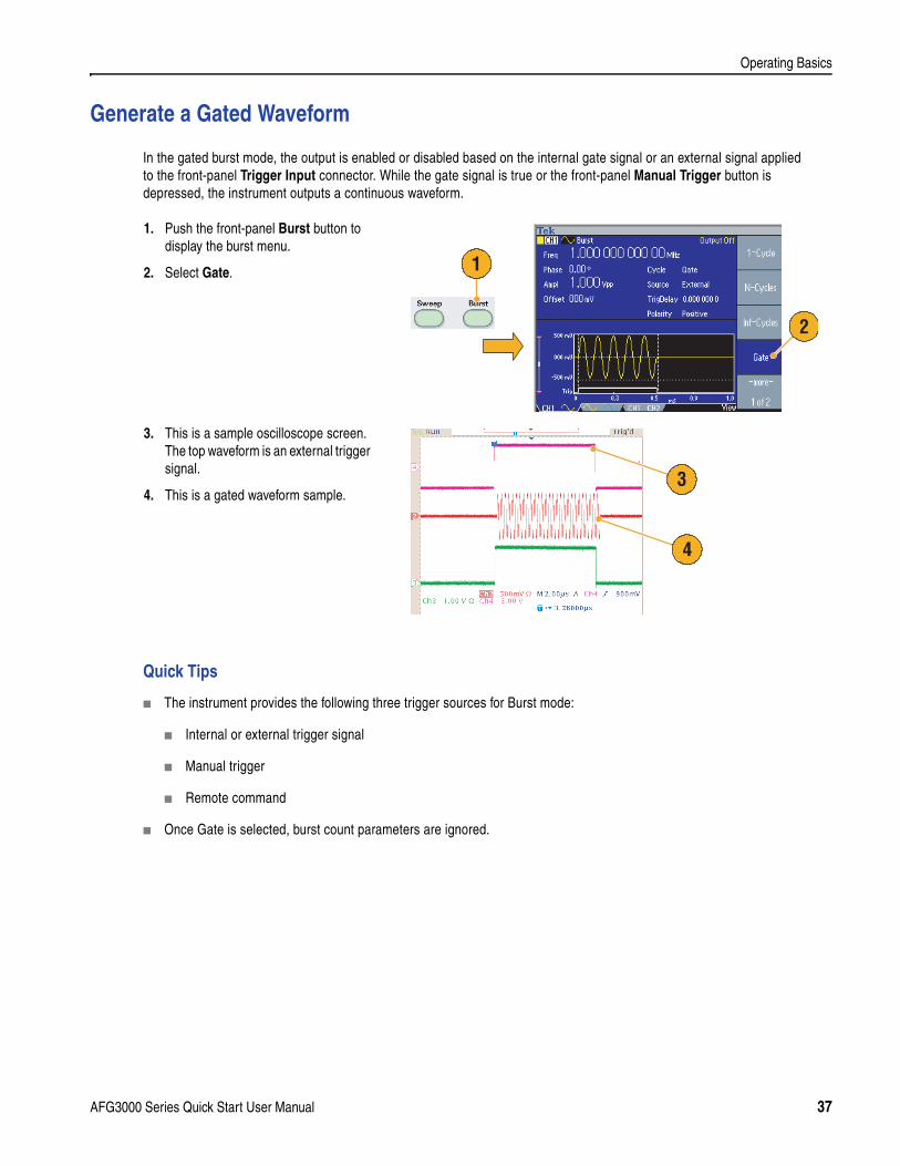
Generate a Gated Waveform
In the gated burst mode, the output is enabled or disabled based on the internal gate signal or an external signal applied to the front-panel Trigger Input connector. While the gate signal is true or the front-panel Manual Trigger button is depressed, the instrument outputs a continuous waveform.
Quick Tips
The instrument provides the following three trigger sources for Burst mode:
Internal or external trigger signal
Manual trigger
Remote command
Once Gate is selected, burst count parameters are ignored.
1. Push the front-panel Burst button to display the burst menu.
2. Select Gate.
3. This is a sample oscilloscope screen. The top waveform is an external trigger signal.
4. This is a gated waveform sample.
2
1
3
4
AFG3000 Series Quick Start User Manual 37
Operating Basics
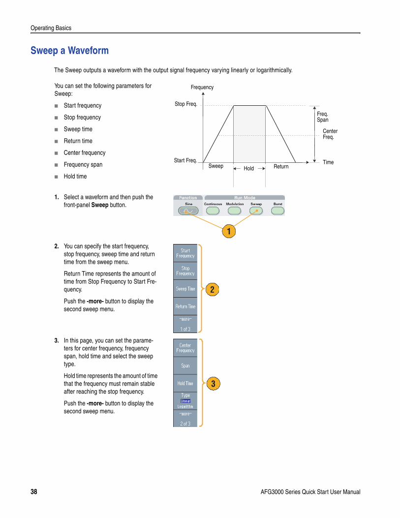
Sweep a Waveform
The Sweep outputs a waveform with the output signal frequency varying linearly or logarithmically.
You can set the following parameters for Sweep:
Start frequency
Stop frequency
Sweep time
Return time
Center frequency
Frequency span
Hold time
1. Select a waveform and then push the front-panel Sweep button.
2. You can specify the start frequency, stop frequency, sweep time and return time from the sweep menu.
Return Time represents the amount of time from Stop Frequency to Start Fre-quency.
Push the -more- button to display the second sweep menu.
3. In this page, you can set the parame-ters for center frequency, frequency span, hold time and select the sweep type.
Hold time represents the amount of time that the frequency must remain stable after reaching the stop frequency.
Push the -more- button to display the second sweep menu.
Stop Freq.
Start Freq.Hold
Time
CenterFreq.
Freq.Span
Frequency
Sweep Return
1
2
3
38 AFG3000 Series Quick Start User Manual
Operating Basics
Quick Tips
For frequency sweep, you can select a sine, square, ramp, or arbitrary waveform. Pulse, DC, and Noise waveforms cannot be selected.
Once the sweep is selected, the frequency is swept from the sweep start to the sweep stop frequencies.
If a start frequency is lower than a stop frequency, the instrument sweeps from the low frequency to the high frequency.
If a start frequency is higher than a stop frequency, the instrument sweeps from the high frequency to the low frequency.
If you want to return to the Sweep Menu after selecting other menus, push the front-panel Sweep button again.
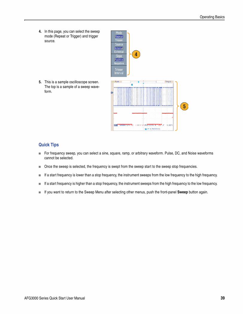
4. In this page, you can select the sweep mode (Repeat or Trigger) and trigger source.
5. This is a sample oscilloscope screen. The top is a sample of a sweep wave-form.
4
5
AFG3000 Series Quick Start User Manual 39
Operating Basics
Modulate a Waveform
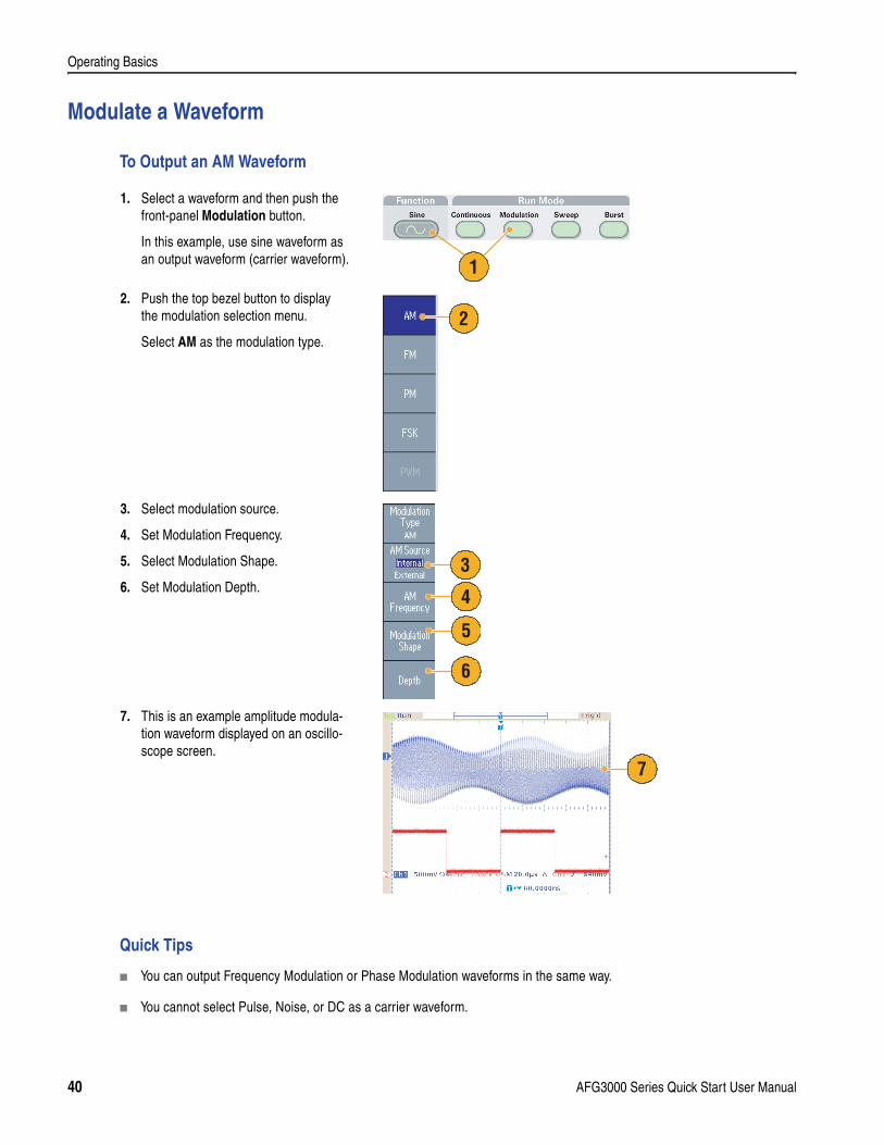
To Output an AM Waveform
Quick Tips
You can output Frequency Modulation or Phase Modulation waveforms in the same way.
You cannot select Pulse, Noise, or DC as a carrier waveform.
1. Select a waveform and then push the front-panel Modulation button.
In this example, use sine waveform as an output waveform (carrier waveform).
2. Push the top bezel button to display the modulation selection menu.
Select AM as the modulation type.
3. Select modulation source.
4. Set Modulation Frequency.
5. Select Modulation Shape.
6. Set Modulation Depth.
7. This is an example amplitude modula-tion waveform displayed on an oscillo-scope screen.
1
2
3
4
5
6
7
40 AFG3000 Series Quick Start User Manual
Operating Basics
You can select an internal or external signal as an AM source. If you select an external source and set the modulation depth to 120%, the output will be at the maximum amplitude when a ±1 Vp-p signal is applied to the rear panel EXT MODULATION INPUT connector.
You can select a modulation shape from the internal memory or USB memory.
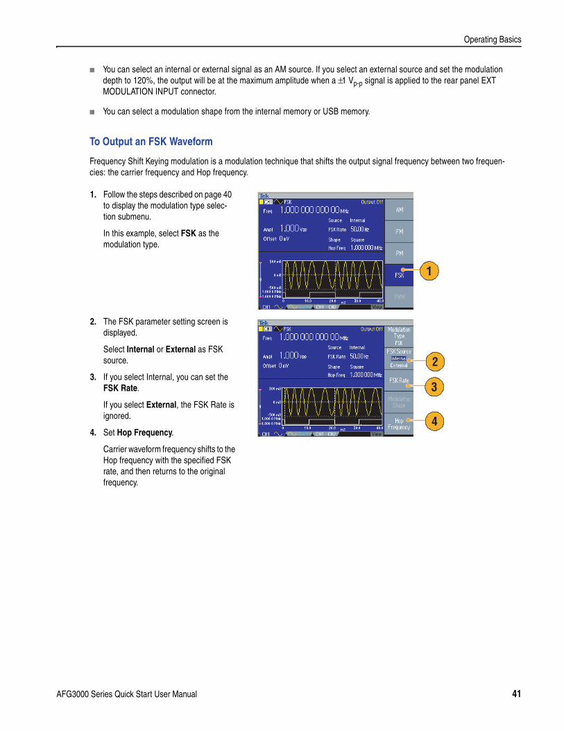
To Output an FSK Waveform
Frequency Shift Keying modulation is a modulation technique that shifts the output signal frequency between two frequen-cies: the carrier frequency and Hop frequency.
1. Follow the steps described on page 40 to display the modulation type selec-tion submenu.
In this example, select FSK as the modulation type.
2. The FSK parameter setting screen is displayed.
Select Internal or External as FSK source.
3. If you select Internal, you can set the FSK Rate.
If you select External, the FSK Rate is ignored.
4. Set Hop Frequency.
Carrier waveform frequency shifts to the Hop frequency with the specified FSK rate, and then returns to the original frequency.
1
2
3
4
AFG3000 Series Quick Start User Manual 41
Operating Basics
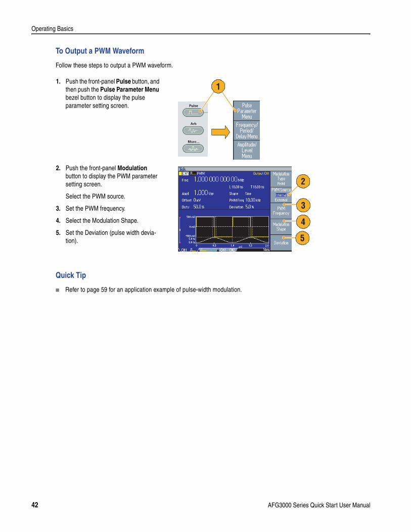
To Output a PWM Waveform
Follow these steps to output a PWM waveform.
Quick Tip
Refer to page 59 for an application example of pulse-width modulation.
1. Push the front-panel Pulse button, and then push the Pulse Parameter Menu bezel button to display the pulse parameter setting screen.
2. Push the front-panel Modulation button to display the PWM parameter setting screen.
Select the PWM source.
3. Set the PWM frequency.
4. Select the Modulation Shape.
5. Set the Deviation (pulse width devia-tion).
1
3
4
5
2
42 AFG3000 Series Quick Start User Manual
Operating Basics
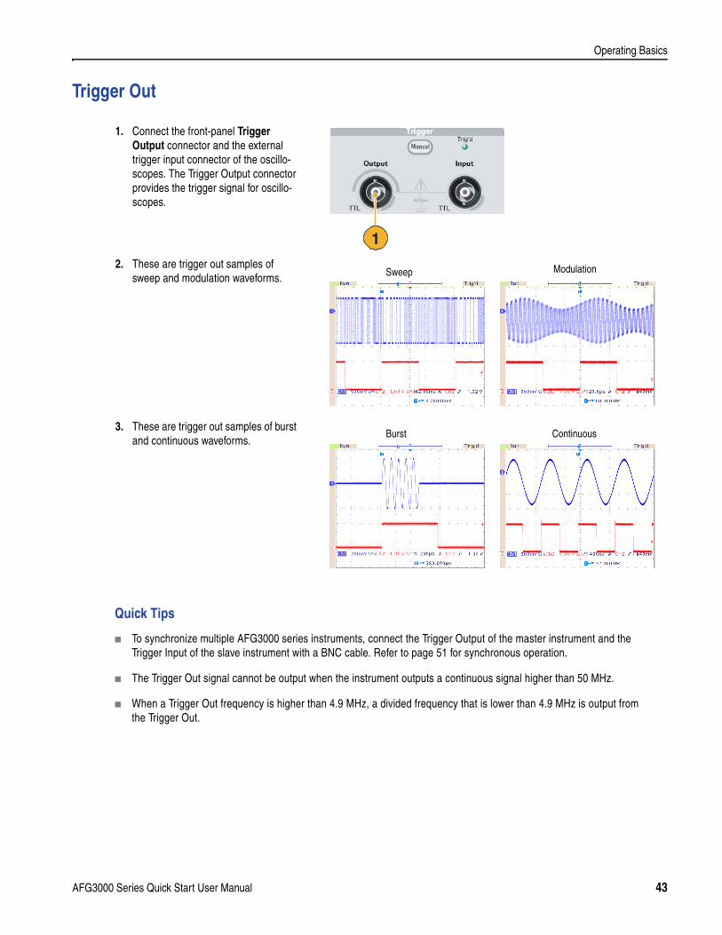
Trigger Out
Quick Tips
To synchronize multiple AFG3000 series instruments, connect the Trigger Output of the master instrument and the Trigger Input of the slave instrument with a BNC cable. Refer to page 51 for synchronous operation.
The Trigger Out signal cannot be output when the instrument outputs a continuous signal higher than 50 MHz.
When a Trigger Out frequency is higher than 4.9 MHz, a divided frequency that is lower than 4.9 MHz is output from the Trigger Out.
1. Connect the front-panel Trigger Output connector and the external trigger input connector of the oscillo-scopes. The Trigger Output connector provides the trigger signal for oscillo-scopes.
2. These are trigger out samples of sweep and modulation waveforms.
3. These are trigger out samples of burst and continuous waveforms.
1
ModulationSweep
Burst Continuous
AFG3000 Series Quick Start User Manual 43
Operating Basics
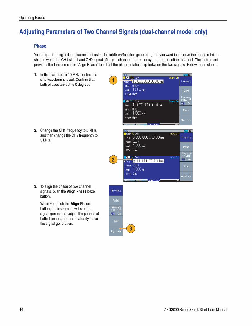
Adjusting Parameters of Two Channel Signals (dual-channel model only)
Phase
You are performing a dual-channel test using the arbitrary/function generator, and you want to observe the phase relation-ship between the CH1 signal and CH2 signal after you change the frequency or period of either channel. The instrument provides the function called “Align Phase” to adjust the phase relationship between the two signals. Follow these steps:
1. In this example, a 10 MHz continuous sine waveform is used. Confirm that both phases are set to 0 degrees.
2. Change the CH1 frequency to 5 MHz, and then change the CH2 frequency to 5 MHz.
3. To align the phase of two channel signals, push the Align Phase bezel button.
When you push the Align Phase button, the instrument will stop the signal generation, adjust the phases of both channels, and automatically restart the signal generation.
1
2
3
44 AFG3000 Series Quick Start User Manual
Operating Basics
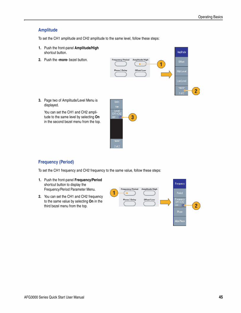
Amplitude
To set the CH1 amplitude and CH2 amplitude to the same level, follow these steps:
Frequency (Period)
To set the CH1 frequency and CH2 frequency to the same value, follow these steps:
1. Push the front-panel Amplitude/High shortcut button.
2. Push the -more- bezel button.
3. Page two of Amplitude/Level Menu is displayed.
You can set the CH1 and CH2 ampli-tude to the same level by selecting On in the second bezel menu from the top.
1. Push the front-panel Frequency/Period shortcut button to display the Frequency/Period Parameter Menu.
2. You can set the CH1 and CH2 frequency to the same value by selecting On in the third bezel menu from the top.
1
2
3
2
1
AFG3000 Series Quick Start User Manual 45
Operating Basics
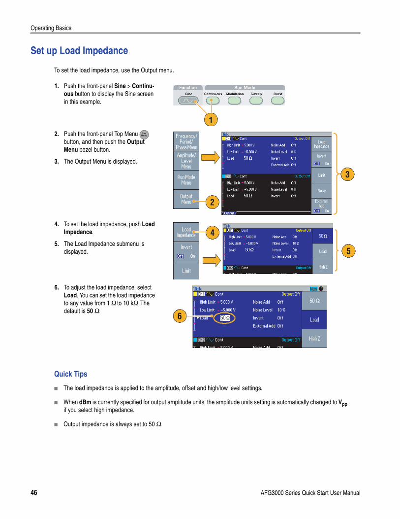
Set up Load Impedance
To set the load impedance, use the Output menu.
Quick Tips
The load impedance is applied to the amplitude, offset and high/low level settings.
When dBm is currently specified for output amplitude units, the amplitude units setting is automatically changed to Vpp if you select high impedance.
Output impedance is always set to 50 Ω.
1. Push the front-panel Sine > Continu-ous button to display the Sine screen in this example.
2. Push the front-panel Top Menu button, and then push the Output Menu bezel button.
3. The Output Menu is displayed.
4. To set the load impedance, push Load Impedance.
5. The Load Impedance submenu is displayed.
6. To adjust the load impedance, select Load. You can set the load impedance to any value from 1 Ω to 10 kΩ. The default is 50 Ω.
1
2
3
4
5
6
46 AFG3000 Series Quick Start User Manual
Operating Basics
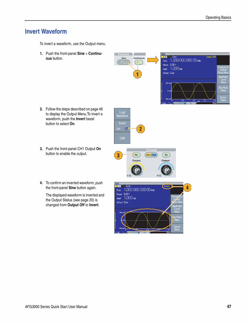
Invert Waveform
To invert a waveform, use the Output menu.
1. Push the front-panel Sine > Continu-ous button.
2. Follow the steps described on page 46 to display the Output Menu.To invert a waveform, push the Invert bezel button to select On.
3. Push the front-panel CH1 Output On button to enable the output.
4. To confirm an inverted waveform, push the front-panel Sine button again.
The displayed waveform is inverted and the Output Status (see page 20) is changed from Output Off to Invert.
1
2
3
4
AFG3000 Series Quick Start User Manual 47
Operating Basics
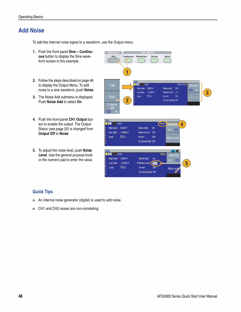
Add Noise
To add the internal noise signal to a waveform, use the Output menu.
Quick Tips
An internal noise generator (digital) is used to add noise.
CH1 and CH2 noises are non-correlating.
1. Push the front-panel Sine > Continu-ous button to display the Sine wave-form screen in this example.
2. Follow the steps described on page 46 to display the Output Menu. To add noise to a sine waveform, push Noise.
3. The Noise Add submenu is displayed. Push Noise Add to select On.
4. Push the front-panel CH1 Output but-ton to enable the output. The Output Status (see page 20) is changed from Output Off to Noise.
5. To adjust the noise level, push Noise Level. Use the general purpose knob or the numeric pad to enter the value.
1
23
4
5
48 AFG3000 Series Quick Start User Manual
Operating Basics
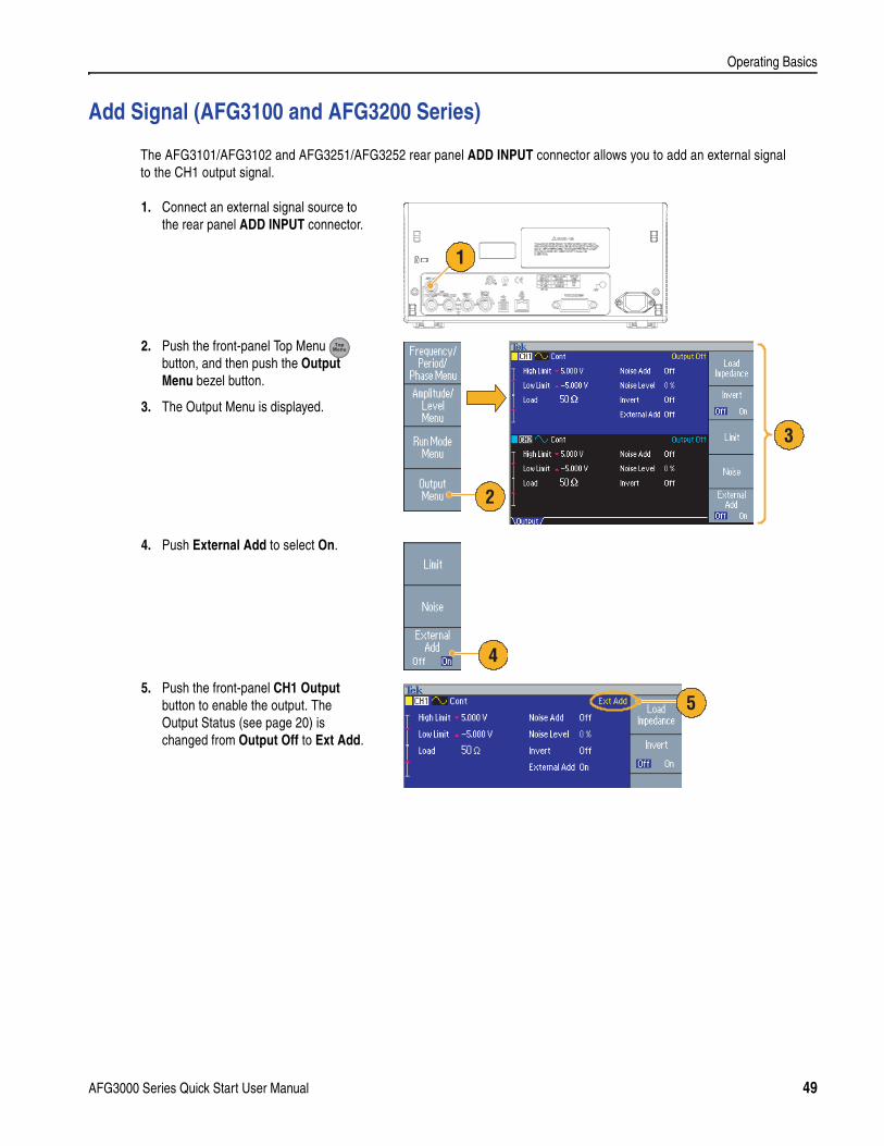
Add Signal (AFG3100 and AFG3200 Series)
The AFG3101/AFG3102 and AFG3251/AFG3252 rear panel ADD INPUT connector allows you to add an external signal to the CH1 output signal.
1. Connect an external signal source to the rear panel ADD INPUT connector.
2. Push the front-panel Top Menu button, and then push the Output Menu bezel button.
3. The Output Menu is displayed.
4. Push External Add to select On.
5. Push the front-panel CH1 Output button to enable the output. The Output Status (see page 20) is changed from Output Off to Ext Add.
120VA
1
2
3
4
5
AFG3000 Series Quick Start User Manual 49
Operating Basics
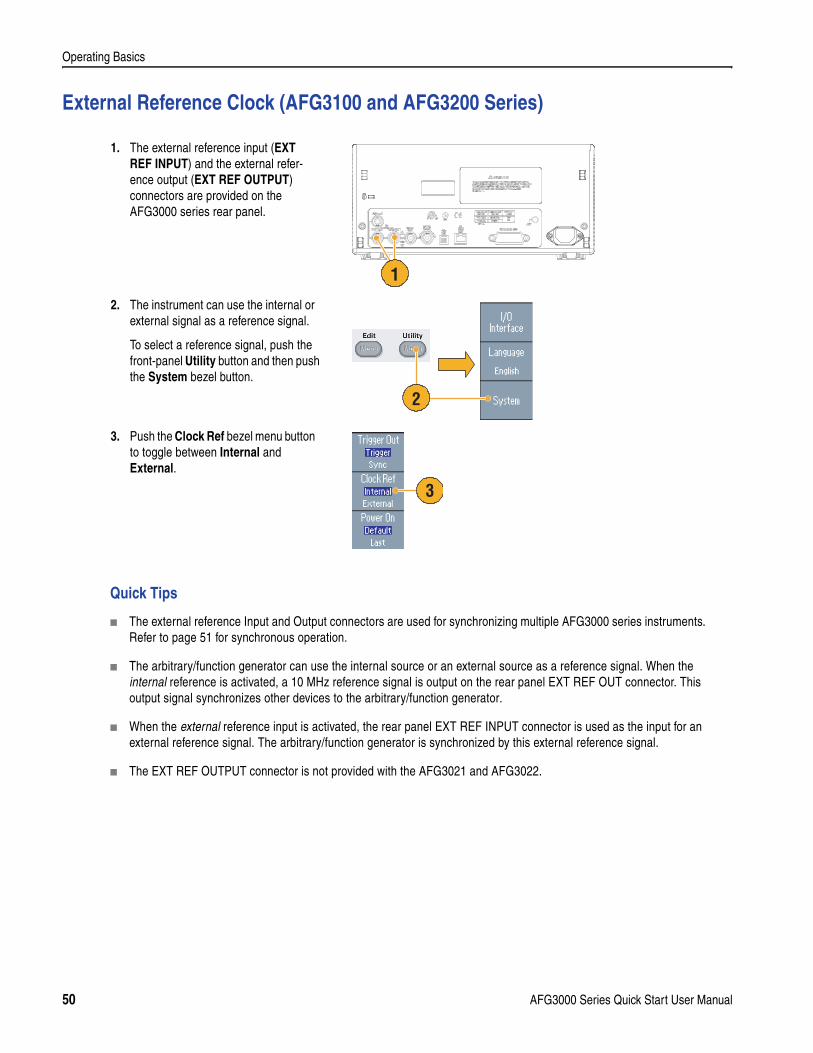
External Reference Clock (AFG3100 and AFG3200 Series)
Quick Tips
The external reference Input and Output connectors are used for synchronizing multiple AFG3000 series instruments. Refer to page 51 for synchronous operation.
The arbitrary/function generator can use the internal source or an external source as a reference signal. When the internal reference is activated, a 10 MHz reference signal is output on the rear panel EXT REF OUT connector. This output signal synchronizes other devices to the arbitrary/function generator.
When the external reference input is activated, the rear panel EXT REF INPUT connector is used as the input for an external reference signal. The arbitrary/function generator is synchronized by this external reference signal.
The EXT REF OUTPUT connector is not provided with the AFG3021 and AFG3022.
1. The external reference input (EXT REF INPUT) and the external refer-ence output (EXT REF OUTPUT) connectors are provided on the AFG3000 series rear panel.
2. The instrument can use the internal or external signal as a reference signal.
To select a reference signal, push the front-panel Utility button and then push the System bezel button.
3. Push the Clock Ref bezel menu button to toggle between Internal and External.
120VA
1
2
3
50 AFG3000 Series Quick Start User Manual
Operating Basics
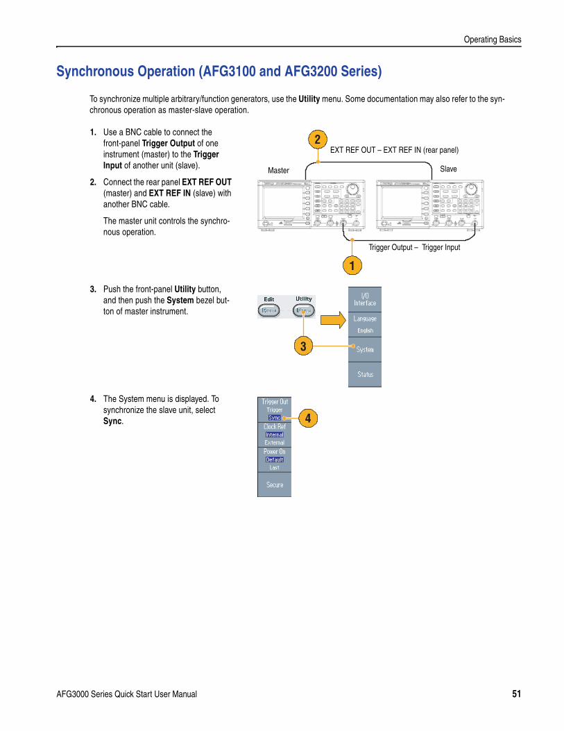
Synchronous Operation (AFG3100 and AFG3200 Series)
To synchronize multiple arbitrary/function generators, use the Utility menu. Some documentation may also refer to the syn-chronous operation as master-slave operation.
1. Use a BNC cable to connect the front-panel Trigger Output of one instrument (master) to the Trigger Input of another unit (slave).
2. Connect the rear panel EXT REF OUT (master) and EXT REF IN (slave) with another BNC cable.
The master unit controls the synchro-nous operation.
3. Push the front-panel Utility button, and then push the System bezel but-ton of master instrument.
4. The System menu is displayed. To synchronize the slave unit, select Sync.
1
2
Master Slave
Trigger Output – Trigger Input
EXT REF OUT – EXT REF IN (rear panel)
3
4
AFG3000 Series Quick Start User Manual 51
Operating Basics
USB Memory
A USB memory connector is provided with all the Tektronix AFG3000 Series Arbitrary/Function Generators to allow you to perform the following tasks:
Save or recall user-defined waveforms to/from a USB memory
Save or recall setups to/from files on a USB memory
Update your arbitrary/function generator firmware
For further information on Save/Recall, see page 55. For updating your arbitrary/function generator, see page 14.
Quick Tip
Use a USB memory with cross section smaller than 20 mm x 12 mm to connect to the AFG3000 series front panel USB connector. To connect a larger USB memory, use an extention cord.
CAUTION. Do not remove USB memory while writing or reading data. It may cause data loss and the USB memory may be damaged.
Before reinserting a USB memory after removing it from the instrument, wait at least one second.
Do not repeat insertion and removal of USB memory without waiting one second each time to avoid damage to the instru-ment.
52 AFG3000 Series Quick Start User Manual
Operating Basics
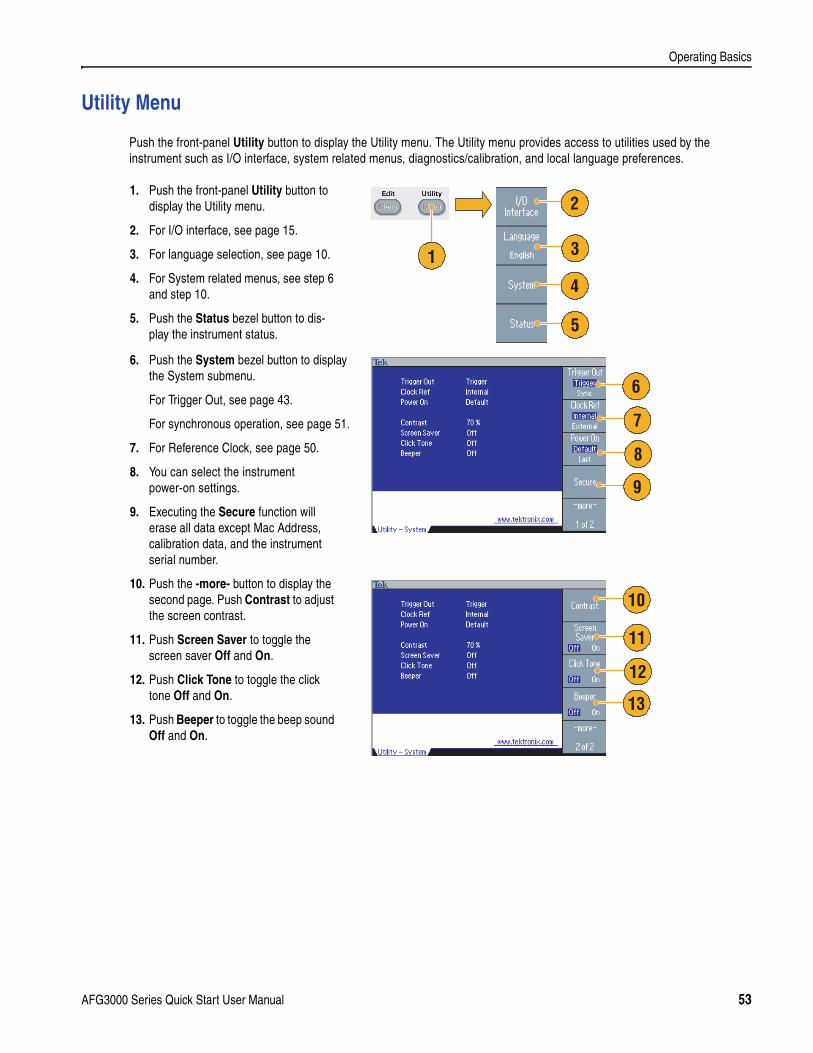
Utility Menu
Push the front-panel Utility button to display the Utility menu. The Utility menu provides access to utilities used by the instrument such as I/O interface, system related menus, diagnostics/calibration, and local language preferences.
1. Push the front-panel Utility button to display the Utility menu.
2. For I/O interface, see page 15.
3. For language selection, see page 10.
4. For System related menus, see step 6 and step 10.
5. Push the Status bezel button to dis-play the instrument status.
6. Push the System bezel button to display the System submenu.
For Trigger Out, see page 43.
For synchronous operation, see page 51.
7. For Reference Clock, see page 50.
8. You can select the instrument power-on settings.
9. Executing the Secure function will erase all data except Mac Address, calibration data, and the instrument serial number.
10. Push the -more- button to display the second page. Push Contrast to adjust the screen contrast.
11. Push Screen Saver to toggle the screen saver Off and On.
12. Push Click Tone to toggle the click tone Off and On.
13. Push Beeper to toggle the beep sound Off and On.
1
2
3
4
5
6
7
8
9
10
11
12
13
AFG3000 Series Quick Start User Manual 53
Operating Basics
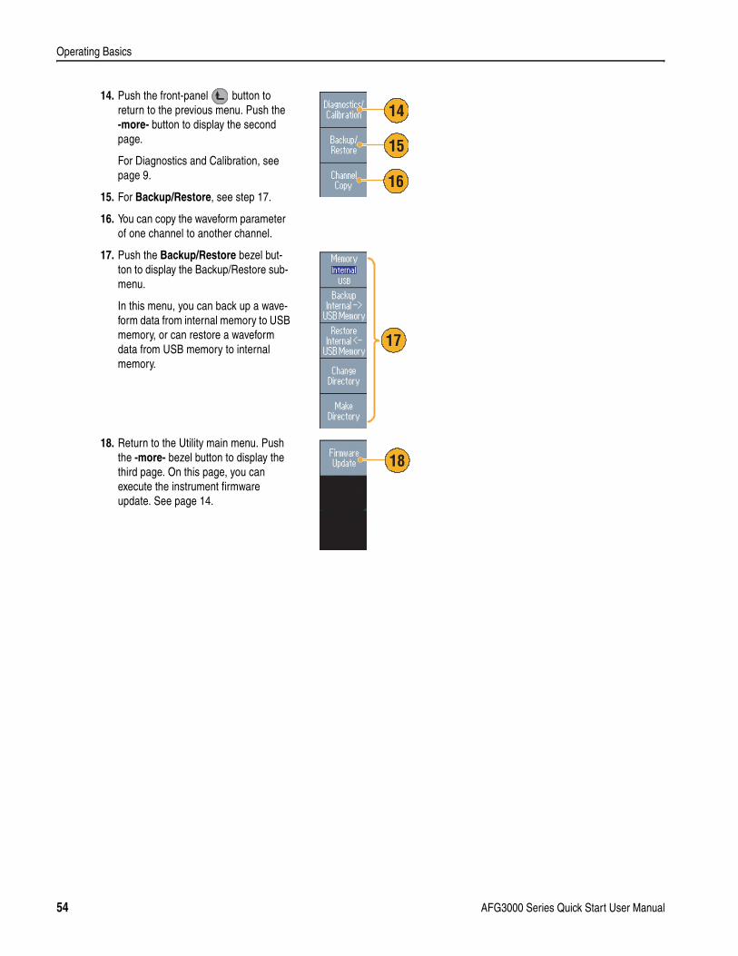
14. Push the front-panel button to return to the previous menu. Push the -more- button to display the second page.
For Diagnostics and Calibration, see page 9.
15. For Backup/Restore, see step 17.
16. You can copy the waveform parameter of one channel to another channel.
17. Push the Backup/Restore bezel but-ton to display the Backup/Restore sub-menu.
In this menu, you can back up a wave-form data from internal memory to USB memory, or can restore a waveform data from USB memory to internal memory.
18. Return to the Utility main menu. Push the -more- bezel button to display the third page. On this page, you can execute the instrument firmware update. See page 14.
14
15
16
17
18
54 AFG3000 Series Quick Start User Manual
Operating Basics
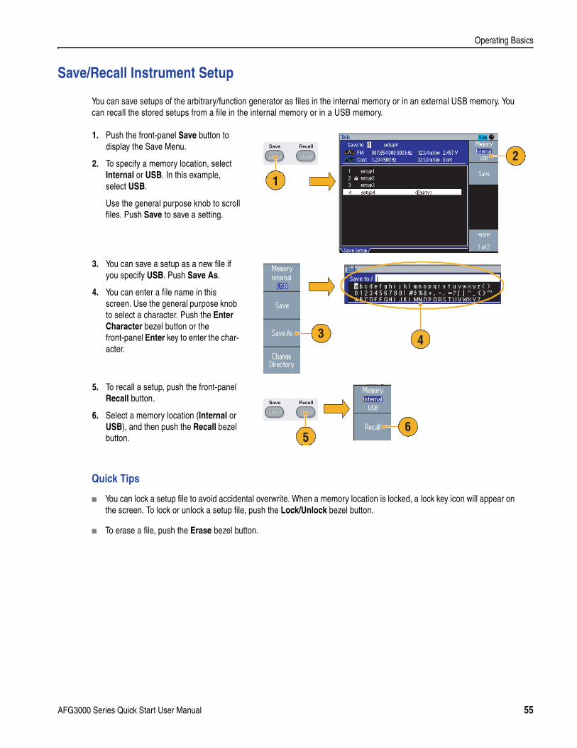
Save/Recall Instrument Setup
You can save setups of the arbitrary/function generator as files in the internal memory or in an external USB memory. You can recall the stored setups from a file in the internal memory or in a USB memory.
Quick Tips
You can lock a setup file to avoid accidental overwrite. When a memory location is locked, a lock key icon will appear on the screen. To lock or unlock a setup file, push the Lock/Unlock bezel button.
To erase a file, push the Erase bezel button.
1. Push the front-panel Save button to display the Save Menu.
2. To specify a memory location, select Internal or USB. In this example, select USB.
Use the general purpose knob to scroll files. Push Save to save a setting.
3. You can save a setup as a new file if you specify USB. Push Save As.
4. You can enter a file name in this screen. Use the general purpose knob to select a character. Push the Enter Character bezel button or the front-panel Enter key to enter the char-acter.
5. To recall a setup, push the front-panel Recall button.
6. Select a memory location (Internal or USB), and then push the Recall bezel button.
2
1
3 4
65
AFG3000 Series Quick Start User Manual 55
Operating Basics
ArbExpress
ArbExpress is a Windows-based software for creating and editing waveforms for Tektronix AWG and AFG instruments. With ArbExpress you can create and edit waveforms, transfer waveforms to and from Tektronix oscilloscopes and AFG3000 Series Arbitrary/Function Generators, and remotely control the arbitrary/function generators.
The following table and bulleted list describe the system requirements and general features.
Create waveforms from standard waveform templates
Modify and transfer waveforms to perform DUT level tests
Directly import waveforms from an oscilloscope
Send waveforms to AWG/AFG instruments directly from ArbExpress or MATLAB
Math operations on waveforms
For more information on ArbExpress, refer to the ArbExpress online help.
System Requirements
OS Supported Windows XP Professionalor Windows 2000or Windows 98/Meor Windows NT
Minimum PC Requirements Pentium III 800 MHz and higher
256 MB RAM
300 MB free hard disk
Microsoft Internet Explorer 5.01 and higher.NET Framework 1.1 Redistributable
800 x 600 Display resolution
Oscilloscope Requirements TekVISA version 2.03 or above
56 AFG3000 Series Quick Start User Manual
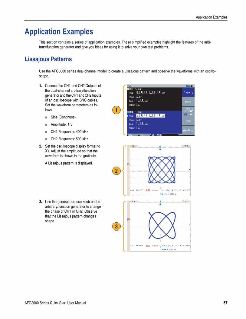
Application Examples
Application ExamplesThis section contains a series of application examples. These simplified examples highlight the features of the arbi-trary/function generator and give you ideas for using it to solve your own test problems.
Lissajous Patterns
Use the AFG3000 series dual-channel model to create a Lissajous pattern and observe the waveforms with an oscillo-scope.
1. Connect the CH1 and CH2 Outputs of the dual-channel arbitrary/function generator and the CH1 and CH2 Inputs of an oscilloscope with BNC cables. Set the waveform parameters as fol-lows:
Sine (Continuos)
Amplitude: 1 V
CH1 Frequency: 400 kHz
CH2 Frequency: 500 kHz
2. Set the oscilloscope display format to XY. Adjust the amplitude so that the waveform is shown in the graticule.
A Lissajous pattern is displayed.
3. Use the general purpose knob on the arbitrary/function generator to change the phase of CH1 or CH2. Observe that the Lissajous pattern changes shape.
1
2
3
AFG3000 Series Quick Start User Manual 57
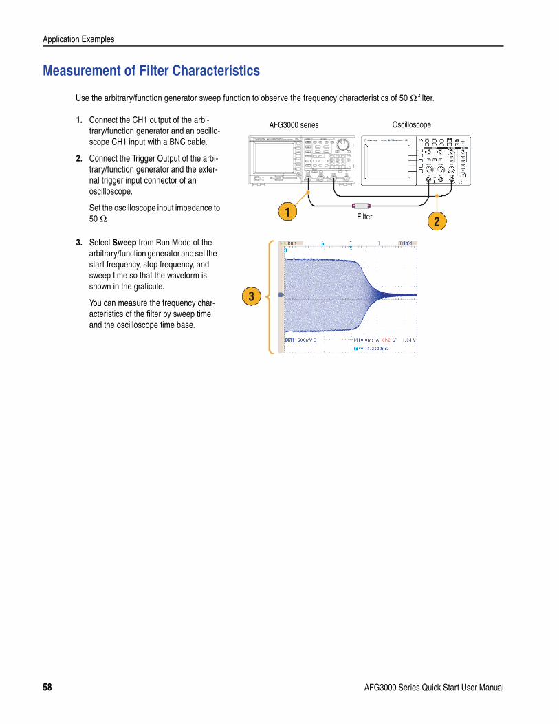
Application Examples
Measurement of Filter Characteristics
Use the arbitrary/function generator sweep function to observe the frequency characteristics of 50 Ω filter.
1. Connect the CH1 output of the arbi-trary/function generator and an oscillo-scope CH1 input with a BNC cable.
2. Connect the Trigger Output of the arbi-trary/function generator and the exter-nal trigger input connector of an oscilloscope.
Set the oscilloscope input impedance to 50 Ω.
3. Select Sweep from Run Mode of the arbitrary/function generator and set the start frequency, stop frequency, and sweep time so that the waveform is shown in the graticule.
You can measure the frequency char-acteristics of the filter by sweep time and the oscilloscope time base.
21
AFG3000 series Oscilloscope
Filter
3
58 AFG3000 Series Quick Start User Manual
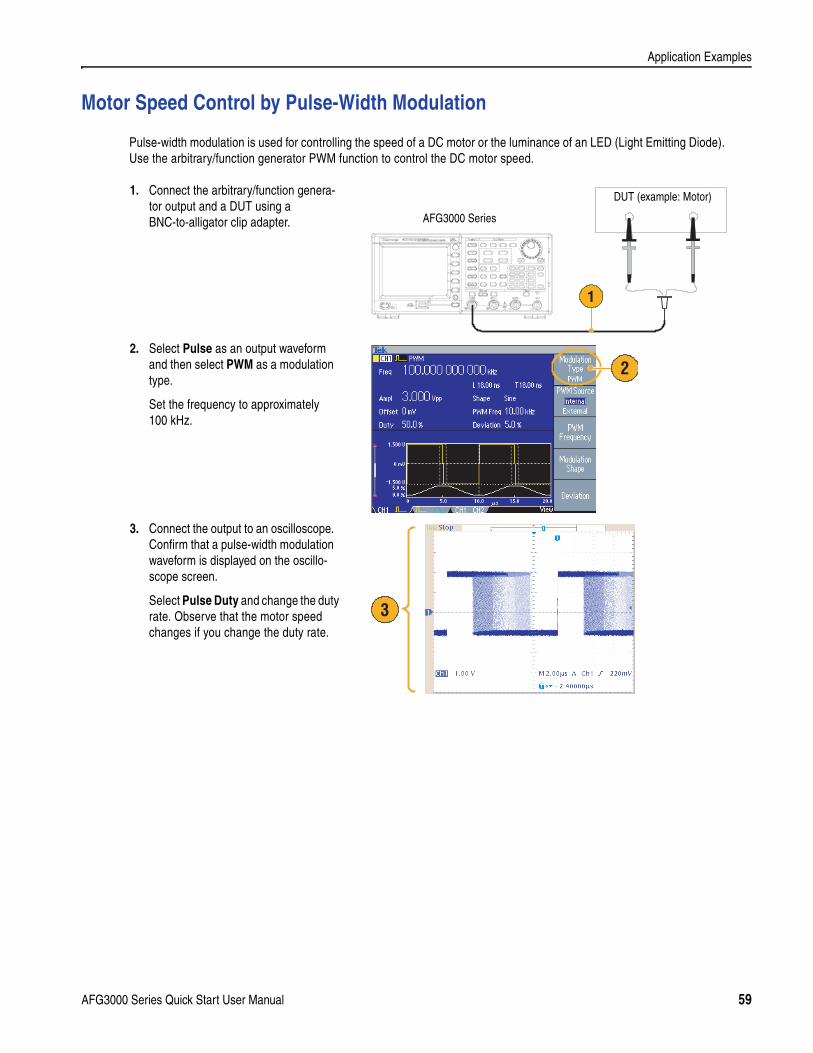
Application Examples
Motor Speed Control by Pulse-Width Modulation
Pulse-width modulation is used for controlling the speed of a DC motor or the luminance of an LED (Light Emitting Diode). Use the arbitrary/function generator PWM function to control the DC motor speed.
1. Connect the arbitrary/function genera-tor output and a DUT using a BNC-to-alligator clip adapter.
2. Select Pulse as an output waveform and then select PWM as a modulation type.
Set the frequency to approximately 100 kHz.
3. Connect the output to an oscilloscope. Confirm that a pulse-width modulation waveform is displayed on the oscillo-scope screen.
Select Pulse Duty and change the duty rate. Observe that the motor speed changes if you change the duty rate.
1
AFG3000 Series
DUT (example: Motor)
2
3
AFG3000 Series Quick Start User Manual 59
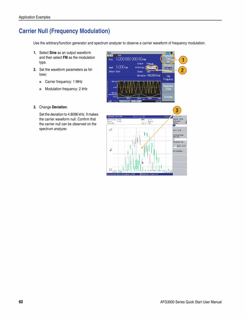
Application Examples
Carrier Null (Frequency Modulation)
Use the arbitrary/function generator and spectrum analyzer to observe a carrier waveform of frequency modulation.
1. Select Sine as an output waveform and then select FM as the modulation type.
2. Set the waveform parameters as fol-lows:
Carrier frequency: 1 MHz
Modulation frequency: 2 kHz
3. Change Deviation.
Set the deviation to 4.8096 kHz. It makes the carrier waveform null. Confirm that the carrier null can be observed on the spectrum analyzer.
1
2
3
60 AFG3000 Series Quick Start User Manual
Specifications
SpecificationsThis section contains the specifications for the AFG3000 Series Arbitrary/Function Generators. All specifications are guaranteed unless noted as “typical”. Typical specifications are provided for your convenience but are not guaranteed. Specifications that are marked with symbol are checked in Performance Verification section of the service manual, an optional accessory.
All specifications apply to the arbitrary/function generator unless noted otherwise. These specifications are valid under three conditions:
The arbitrary/function generator must have been calibrated/adjusted at an ambient temperature between +20 ° C and +30 ° C.
The arbitrary/function generator must have been operating continuously for 20 minutes within the specified operating temperature range.
The instrument must be in an environment with temperature, altitude, and humidity with the operating limits described in these specifications.
Electrical
Operating Mode
Run Mode Continuous, Modulation, Sweep, and Burst
Burst Count 1 to 1,000,000 cycles or Infinite
Internal Trigger Rate 1.000 ms to 500.0 s
Waveforms
Standard Sine, Square, Pulse, Ramp, More (Sin(x)/x, Noise, DC, Gaussian, Lorentz, Exponen-tial Rise, Exponential Decay, and Haversine)
Arbitrary Waveform AFG3021/AFG3022 AFG3101/AFG3102 AFG3251/AFG3252
Waveform Length 2 to 65,536 2 to 16,384
>16,384 to 131,072
2 to 16,384
>16,384 to 131,072
Sampling Rate 250 MS/s 1 GS/s 250 MS/s 2 GS/s 250 MS/s
Resolution 14 bits
Non-volatile Waveform Memory 4
AFG3000 Series Quick Start User Manual 61
Specifications
Frequency AFG3021/AFG3022 AFG3101/AFG3102 AFG3251/AFG3252
Sine1 1 mHz to 25 MHz 1 mHz to 100 MHz 1 mHz to 240 MHz
Square, Pulse 1 mHz to 12.5 MHz 1 mHz to 50 MHz 1 mHz to 120 MHz
Ramp, Sin(x)/x, Gaussian, Lorentz, Exponential Rise, Exponential Decay,Haversine
1 mHz to 250 kHz 1 mHz to 1 MHz 1 mHz to 2.4 MHz
Arbitrary 1 mHz to 12.5 MHz 1 mHz to 50 MHz 1 mHz to 120 MHz
Resolution 1 µHz or 12 digits
Accuracy (Stability) ±1 ppm, 0 ° C to 50 ° C
Accuracy (Aging) ±1 ppm/year
Phase (except DC, Noise, Pulse)
Range2 –180.00° to +180.00°Lead Delay (Pulse)
Range 0 ps to Period – [Pulse Width + 0.8 * (Leading Edge Time + Trailing Edge Time)]
Resolution 10 ps or 8 digits
Amplitude (50 Ω) AFG3021/AFG3022 AFG3101/AFG3102 AFG3251/AFG3252
Range3, 4 10 mVp-p to 10 Vp-p 20 mVp-p to 10 Vp-p 50 mVp-p to 5 Vp-p
Accuracy ±(1% of setting +1 mV) (1 kHz sine waveform, 0 V offset, >10 mVp-p amplitude)
Resolution 0.1 mVp-p, 0.1 mVrms, 1 mV, 0.1 dBm or 4 digits
Units5 Vp-p, Vrms, dBm, and Volt (High Level and Low Level)
Output Impedance 50 ΩDC Offset (50 Ω) AFG3021/AFG3022 AFG3101/AFG3102 AFG3251/AFG3252
Range6 ±5 Vpk ac + dc into 50 Ω ±2.5 Vpk ac + dc into 50 Ω
Accuracy7 ±(1 % of |setting| +5 mV + 0.5 % of amplitude (Vp-p))
Resolution 1 mV
Internal Noise Add
Range 0.0 % to 50 % of amplitude setting (Vp-p) of signal waveform
Resolution 1 %
1. Triggered/Gated Burst Mode:AFG3021/AFG3022, 1 mHz to 12.5 MHzAFG3101/AFG3102, 1 mHz to 50 MHzAFG3251/AFG3252, 1 mHz to 120 MHz
2. Resolution: 0.01° (sine), 0.1° (other standard waveforms)
3. AFG3021/AFG3022: 20 mVp-p to 20 Vp-p into open circuit loadAFG3101/AFG3102: 40 mVp-p to 20 Vp-p into open circuit loadAFG3251/AFG3252: 100 mVp-p to 10 Vp-p into open circuit load
4. AFG3251/AFG3252 (frequency range: >200 MHz to 240 MHz): 50 mVp-p to 4 Vp-p into 50 Ω, 100 mVp-p to 8 Vp-p into open circuit load
5. dBm is used only for sine waveform.
6. AFG3021/AFG3022 and AFG3101/AFG3102: ±10 Vpk ac + dc into open circuit loadAFG3251/AFG3252: ±5 Vpk ac + dc into open circuit load
7. AFG3021/AFG3022 and AFG3101/AFG3102: Add 0.5 mV per ° C for operation outside the range of 20 ° C to 30 ° C.AFG3251/AFG3252: Add 2.0 mV per ° C for operation outside the range of 20 ° C to 30 ° C.
Waveforms (cont.)
62 AFG3000 Series Quick Start User Manual
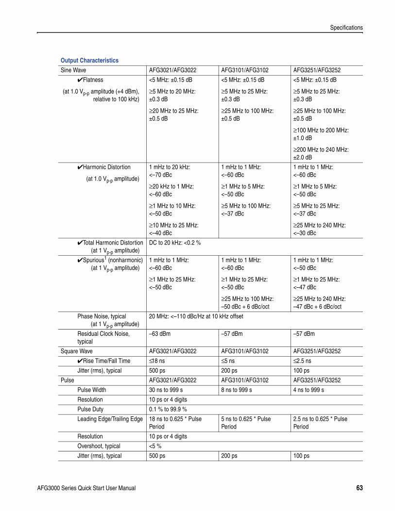
Specifications
Output Characteristics
Sine Wave AFG3021/AFG3022 AFG3101/AFG3102 AFG3251/AFG3252
Flatness
(at 1.0 Vp-p amplitude (+4 dBm),relative to 100 kHz)
<5 MHz: ±0.15 dB
≥5 MHz to 20 MHz: ±0.3 dB
≥20 MHz to 25 MHz: ±0.5 dB
<5 MHz: ±0.15 dB
≥5 MHz to 25 MHz: ±0.3 dB
≥25 MHz to 100 MHz: ±0.5 dB
<5 MHz: ±0.15 dB
≥5 MHz to 25 MHz: ±0.3 dB
≥25 MHz to 100 MHz: ±0.5 dB
≥100 MHz to 200 MHz: ±1.0 dB
≥200 MHz to 240 MHz: ±2.0 dB
Harmonic Distortion
(at 1.0 Vp-p amplitude)
1 mHz to 20 kHz: <–70 dBc
≥20 kHz to 1 MHz: <–60 dBc
≥1 MHz to 10 MHz: <–50 dBc
≥10 MHz to 25 MHz: <–40 dBc
1 mHz to 1 MHz: <–60 dBc
≥1 MHz to 5 MHz: <–50 dBc
≥5 MHz to 100 MHz: <–37 dBc
1 mHz to 1 MHz: <–60 dBc
≥1 MHz to 5 MHz: <–50 dBc
≥5 MHz to 25 MHz: <–37 dBc
≥25 MHz to 240 MHz: <–30 dBc
Total Harmonic Distortion (at 1 Vp-p amplitude)
DC to 20 kHz: <0.2 %
Spurious1 (nonharmonic) (at 1 Vp-p amplitude)
1 mHz to 1 MHz: <–60 dBc
≥1 MHz to 25 MHz: <–50 dBc
1 mHz to 1 MHz: <–60 dBc
≥1 MHz to 25 MHz: <–50 dBc
≥25 MHz to 100 MHz: –50 dBc + 6 dBc/oct
1 mHz to 1 MHz: <–50 dBc
≥1 MHz to 25 MHz: <–47 dBc
≥25 MHz to 240 MHz: –47 dBc + 6 dBc/oct
Phase Noise, typical (at 1 Vp-p amplitude)
20 MHz: <–110 dBc/Hz at 10 kHz offset
Residual Clock Noise, typical
–63 dBm –57 dBm –57 dBm
Square Wave AFG3021/AFG3022 AFG3101/AFG3102 AFG3251/AFG3252
Rise Time/Fall Time ≤ 18 ns ≤ 5 ns ≤ 2.5 ns
Jitter (rms), typical 500 ps 200 ps 100 ps
Pulse AFG3021/AFG3022 AFG3101/AFG3102 AFG3251/AFG3252
Pulse Width 30 ns to 999 s 8 ns to 999 s 4 ns to 999 s
Resolution 10 ps or 4 digits
Pulse Duty 0.1 % to 99.9 %
Leading Edge/Trailing Edge 18 ns to 0.625 * Pulse Period
5 ns to 0.625 * Pulse Period
2.5 ns to 0.625 * Pulse Period
Resolution 10 ps or 4 digits
Overshoot, typical <5 %
Jitter (rms), typical 500 ps 200 ps 100 ps
AFG3000 Series Quick Start User Manual 63
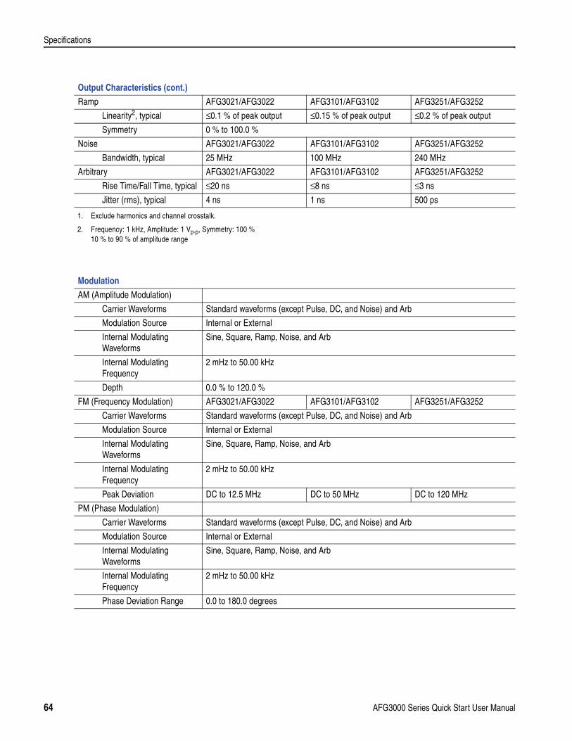
Specifications
Ramp AFG3021/AFG3022 AFG3101/AFG3102 AFG3251/AFG3252
Linearity2, typical ≤ 0.1 % of peak output ≤ 0.15 % of peak output ≤ 0.2 % of peak output
Symmetry 0 % to 100.0 %
Noise AFG3021/AFG3022 AFG3101/AFG3102 AFG3251/AFG3252
Bandwidth, typical 25 MHz 100 MHz 240 MHz
Arbitrary AFG3021/AFG3022 AFG3101/AFG3102 AFG3251/AFG3252
Rise Time/Fall Time, typical ≤ 20 ns ≤ 8 ns ≤ 3 ns
Jitter (rms), typical 4 ns 1 ns 500 ps
1. Exclude harmonics and channel crosstalk.
2. Frequency: 1 kHz, Amplitude: 1 Vp-p, Symmetry: 100 %10 % to 90 % of amplitude range
Modulation
AM (Amplitude Modulation)
Carrier Waveforms Standard waveforms (except Pulse, DC, and Noise) and Arb
Modulation Source Internal or External
Internal Modulating Waveforms
Sine, Square, Ramp, Noise, and Arb
Internal ModulatingFrequency
2 mHz to 50.00 kHz
Depth 0.0 % to 120.0 %
FM (Frequency Modulation) AFG3021/AFG3022 AFG3101/AFG3102 AFG3251/AFG3252
Carrier Waveforms Standard waveforms (except Pulse, DC, and Noise) and Arb
Modulation Source Internal or External
Internal Modulating Waveforms
Sine, Square, Ramp, Noise, and Arb
Internal ModulatingFrequency
2 mHz to 50.00 kHz
Peak Deviation DC to 12.5 MHz DC to 50 MHz DC to 120 MHz
PM (Phase Modulation)
Carrier Waveforms Standard waveforms (except Pulse, DC, and Noise) and Arb
Modulation Source Internal or External
Internal Modulating Waveforms
Sine, Square, Ramp, Noise, and Arb
Internal ModulatingFrequency
2 mHz to 50.00 kHz
Phase Deviation Range 0.0 to 180.0 degrees
Output Characteristics (cont.)
64 AFG3000 Series Quick Start User Manual
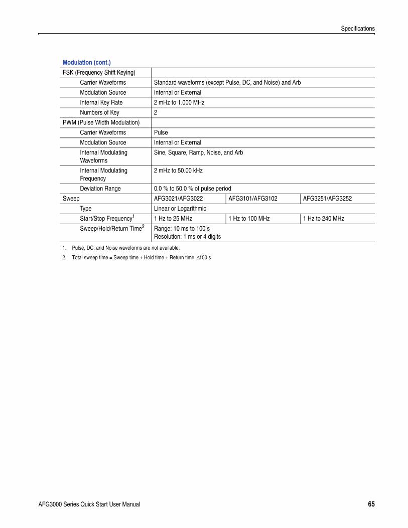
Specifications
FSK (Frequency Shift Keying)
Carrier Waveforms Standard waveforms (except Pulse, DC, and Noise) and Arb
Modulation Source Internal or External
Internal Key Rate 2 mHz to 1.000 MHz
Numbers of Key 2
PWM (Pulse Width Modulation)
Carrier Waveforms Pulse
Modulation Source Internal or External
Internal Modulating Waveforms
Sine, Square, Ramp, Noise, and Arb
Internal ModulatingFrequency
2 mHz to 50.00 kHz
Deviation Range 0.0 % to 50.0 % of pulse period
Sweep AFG3021/AFG3022 AFG3101/AFG3102 AFG3251/AFG3252
Type Linear or Logarithmic
Start/Stop Frequency1 1 Hz to 25 MHz 1 Hz to 100 MHz 1 Hz to 240 MHz
Sweep/Hold/Return Time2 Range: 10 ms to 100 sResolution: 1 ms or 4 digits
1. Pulse, DC, and Noise waveforms are not available.
2. Total sweep time = Sweep time + Hold time + Return time ≤ 100 s
Modulation (cont.)
AFG3000 Series Quick Start User Manual 65
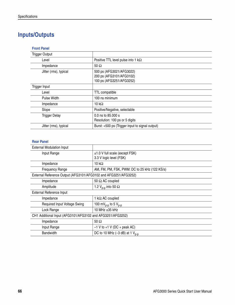
Specifications
Inputs/Outputs
Front Panel
Trigger Output
Level Positive TTL level pulse into 1 kΩImpedance 50 ΩJitter (rms), typical 500 ps (AFG3021/AFG3022)
200 ps (AFG3101/AFG3102)100 ps (AFG3251/AFG3252)
Trigger Input
Level TTL compatible
Pulse Width 100 ns minimum
Impedance 10 kΩSlope Positive/Negative, selectable
Trigger Delay 0.0 ns to 85.000 sResolution: 100 ps or 5 digits
Jitter (rms), typical Burst: <500 ps (Trigger input to signal output)
Rear Panel
External Modulation Input
Input Range ±1.0 V full scale (except FSK)3.3 V logic level (FSK)
Impedance 10 kΩFrequency Range AM, FM, PM, FSK, PWM: DC to 25 kHz (122 KS/s)
External Reference Output (AFG3101/AFG3102 and AFG3251/AFG3252)
Impedance 50 Ω, AC coupled
Amplitude 1.2 Vp-p into 50 ΩExternal Reference Input
Impedance 1 kΩ, AC coupled
Required Input Voltage Swing 100 mVp-p to 5 Vp-p
Lock Range 10 MHz ±35 kHz
CH1 Additional Input (AFG3101/AFG3102 and AFG3251/AFG3252)
Impedance 50 ΩInput Range –1 V to +1 V (DC + peak AC)
Bandwidth DC to 10 MHz (–3 dB) at 1 Vp-p
66 AFG3000 Series Quick Start User Manual
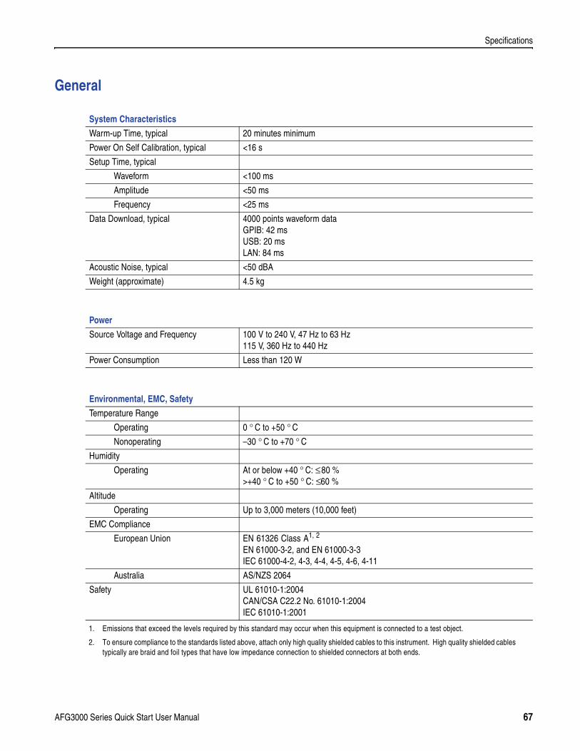
Specifications
General
System Characteristics
Warm-up Time, typical 20 minutes minimum
Power On Self Calibration, typical <16 s
Setup Time, typical
Waveform <100 ms
Amplitude <50 ms
Frequency <25 ms
Data Download, typical 4000 points waveform dataGPIB: 42 msUSB: 20 msLAN: 84 ms
Acoustic Noise, typical <50 dBA
Weight (approximate) 4.5 kg
Power
Source Voltage and Frequency 100 V to 240 V, 47 Hz to 63 Hz115 V, 360 Hz to 440 Hz
Power Consumption Less than 120 W
Environmental, EMC, Safety
Temperature Range
Operating 0 ° C to +50 ° C
Nonoperating –30 ° C to +70 ° C
Humidity
Operating At or below +40 ° C: ≤ 80 %>+40 ° C to +50 ° C: ≤ 60 %
Altitude
Operating Up to 3,000 meters (10,000 feet)
EMC Compliance
European Union EN 61326 Class A1, 2
EN 61000-3-2, and EN 61000-3-3IEC 61000-4-2, 4-3, 4-4, 4-5, 4-6, 4-11
1. Emissions that exceed the levels required by this standard may occur when this equipment is connected to a test object.
2. To ensure compliance to the standards listed above, attach only high quality shielded cables to this instrument. High quality shielded cablestypically are braid and foil types that have low impedance connection to shielded connectors at both ends.
Australia AS/NZS 2064
Safety UL 61010-1:2004CAN/CSA C22.2 No. 61010-1:2004IEC 61010-1:2001
AFG3000 Series Quick Start User Manual 67
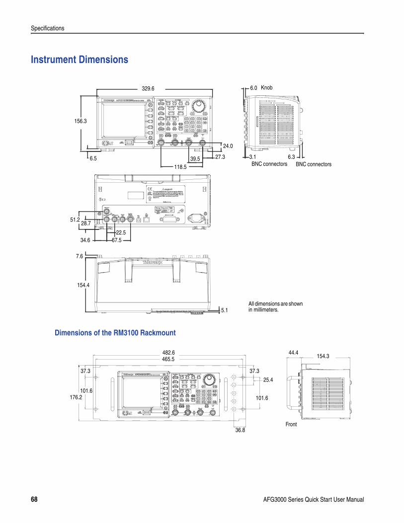
Specifications
Instrument Dimensions
Dimensions of the RM3100 Rackmount
6.33.1
329.6
156.3
24.0
6.5
All dimensions are shown in millimeters.
27.339.5118.5
51.2
67.534.622.5
154.4
7.6
5.1
6.0
BNC connectors
28.7
BNC connectors
Knob
176.2101.6
482.6465.5
37.3
154.344.4
101.6
36.8
37.3
25.4
Front
68 AFG3000 Series Quick Start User Manual
Index
Index
AAccessing Help 4ADD INPUT connector
Add signal 49Rear panel 30
Add Noise 48Add Signal 49Address, Tektronix viAdjusting parameters of two channel
signalAmplitude 45Frequency 45Period 45Phase 44
Align Phase 44Amplitude, To change the units 28Application examples
Frequency modulation 60Lissajous patterns 57Pulse-width modulation 59Sweep 58
ArbExpress 56
BBeeper, Utility menu 53Bezel menu buttons 19Bezel menu, Screen interface 20
CCarrier null, Application examples 60Center frequency, Sweep waveform 38Chassis ground screw, Rear panel 30Click tone, Utility menu 53Connect to a network
Ethernet 15GPIB 16USB interface 15
DDC, Standard waveform 25Default setup 23
Documentation v
EEdit menu 33
Saving a waveform data 34Environmental requirements 6Exponential Decay, Standard waveform
25Exponential Rise, Standard waveform 25EXT MODULATION INPUT connector,
Rear panel 30EXT REF INPUT connector, Rear panel
30EXT REF OUTPUT connector, Rear
panel 30External reference clock, Rear panel 50
FFirmware updates 14Floating ground 12Frequency span, Sweep waveform 38Front panel 19Function buttons 19Fuse adapter, Protect output circuits 11
GGaussian, Standard waveform 25General features 5Generate a burst waveform 36Generate a gated waveform 37Generate a pulse waveform 31Generate a sine waveform 2Generate an arbitrary waveform 32Generate DC 35Generate Noise 35GPIB connector, Rear panel 30
HHaversine, Standard waveform 25Help 4
Hold time, Sweep waveform 38
IInstrument dimensions 68Instrument power-on and power-off 8Instrument settings when powered-on 8Invert waveform 47
LLAN connector, Rear panel 30Level meter, Screen interface 20Lissajous Patterns, Application examples
57Lorentz, Standard waveform 25
MMain display area, Screen interface 20Master-slave operation 51Measurement of filter characteristics,
Application examples 58Menu buttons 19Message display area, Screen interface
20Modify an arbitrary waveform 33Modulate a waveform 40
NNoise, Standard waveform 25
OOperating requirements 6Option buttons 20Output menu
To add Noise 48To add signal 49To invert waveform 47To protect your DUT 13To set up load impedance 46
Output On/Off 29
AFG3000 Series Quick Start User Manual 69
Index
Output statusExt Add 49Invert 47Noise 48Screen interface 20
PPerformance test vPhase | Delay shortcut button 22Phone, Tektronix viPower button 8Power consumption 6Power off 8Power on 8Power supply requirements 6Power switch 19Procedure
To adjust waveform parameters 27To connect to a network 15To generate a pulse waveform 31To generate a sine waveform 2To generate an arbitrary waveform
32To modify an arbitrary waveform 33To output a PWM waveform 42To output an AM waveform 40To output an FSK waveform 41To restore the default setup 23To select a channel 29To select a local language 10To select a waveform 24To select Run Mode 26To sweep a waveform 38
Protect output circuits, Fuse adapter 11Protect your DUT 13Pulse-width modulation, Application
examples 59
QQuick Tutorial 1
RRackmount, dimensions 68Rear panel 30Reference Manual v
Reference signal, Internal or External 50Related documentation vReturn time, Sweep waveform 38Run Mode 26
SSales support viSave/Recall instrument setup 55Screen interface 20Screen saver, Utility menu 53Screen view formats 21Secure function, Utility menu 53Security slot, Rear panel 30Selecting a local language 10Self calibration 9Self test, Utility menu 9Service Manual vService support viSet up load impedance 46Shortcut buttons 19, 22Side-menu buttons 20Sin(x)/x, Standard waveform 25Soft keys 20Specifications 61Standard accessories 7Standard waveforms 24Start frequency, Sweep waveform 38Stop frequency, Sweep waveform 38Sweep time, Sweep waveform 38Sweep waveform, Application exam-
ples 58Synchronous operation 51
TTechnical support viTop Menu button 19Trigger input connector 19Trigger out 43Trigger output connector 19, 43
UUSB connector
Front panel 19Rear panel 30
USB memory 52Firmware updates 14Save/Recall instrument setup 55To generate an arbitrary waveform
32Utility menu 53
Connecting to a network 15Language selection 10Self test and self calibration 9Synchronous operation 51Updating instrument firmware 14
VView button 19, 21View tab, Screen interface 20Voltage units, Conversion table of Vp-p,
Vrms, and dBm 28
WWaveform parameter, how to change 27Web site, Tektronix vi
70 AFG3000 Series Quick Start User Manual


![[Power On] Soirée Connect Tendances 2010](https://img.pdfslide.net/doc/110x75/54b99a894a79598f748b4752/power-on-soiree-connect-tendances-2010.jpg)


![[Power On] Soirée Connect Blogueur](https://img.pdfslide.net/doc/110x75/54b99a8e4a79596f228b45eb/power-on-soiree-connect-blogueur.jpg)