Embed Size (px)
Citation preview
AFIS® DMU Configuration Procedures Introduction Configuration of the Honeywell AFIS® Data Management Unit (DMU) is performed by modifying parameters stored in the DMU configuration module. The configuration module is installed at the rear of the DMU avionics rack, which allows the DMU to be removed and replaced without having to configure the new unit. Parameters stored in the configuration module include the aircraft registration or permanent callsign, airline identifier, default power-up settings, and takeoff and landing report settings. Several parameters which are also modifiable by the flight crew may be configured to a "last state" setting, which means that the state of the parameter at power-down will be the state of the parameter at the next power-up. DMU configuration may be performed in several ways: 1) Through the Control Display Unit (CDU) interface of a Global Flight Management System (FMS). 2) Through the CDU interface of a Collins FMS. 3) By using Procomm Plus™ software on a portable computer connected to the DMU test port with an appropriate interface cable if only Honeywell FMSs and/or Universal Avionics FMSs are installed in the aircraft. Although the DMU may be configured using Procomm Plus regardless of the manufacturer(s) of the FMSs installed in the aircraft, use of the Global FMS and Collins FMS CDU interfaces to configure the DMU are generally preferred because no software, computer, and cable are required. Configuration using Procomm Plus is the sole option when only Honeywell FMSs and/or Universal Avionics FMSs are installed in the aircraft. Please also note that depending on the aircraft type, DMU part number, DMU modification level, and version of Procomm Plus, the actual CDU displays and Procomm Plus screens may differ slightly from those presented in this document. For support of AFIS DMU configuration, please contact the following individuals: Dale Carter AFIS DMU Product Support 913.712.2630 [email protected] James Buckner GDC Datalink Services Support 410.964.7367 [email protected] Nick Cook GDC Datalink Services Support 425.885.8788 [email protected]
AFIS® is a registered trademark of Honeywell International Inc. Procomm Plus™ is a trademark of Symantec Corporation
Global Data Center 15001 NE 36th Street
Redmond, WA 98052 USA 888.634.3330 telephone 425.885.8100 telephone 425.885.8930 facsimile
www.mygdc.com [email protected]
Document 176-9001-998 Version 6 © 2004 Honeywell International Inc.
AFIS DMU Configuration Procedures 2
Procedures 1 Global FMS 1.1 With no power applied to the DMU, remove the test port cover on the front of the DMU.
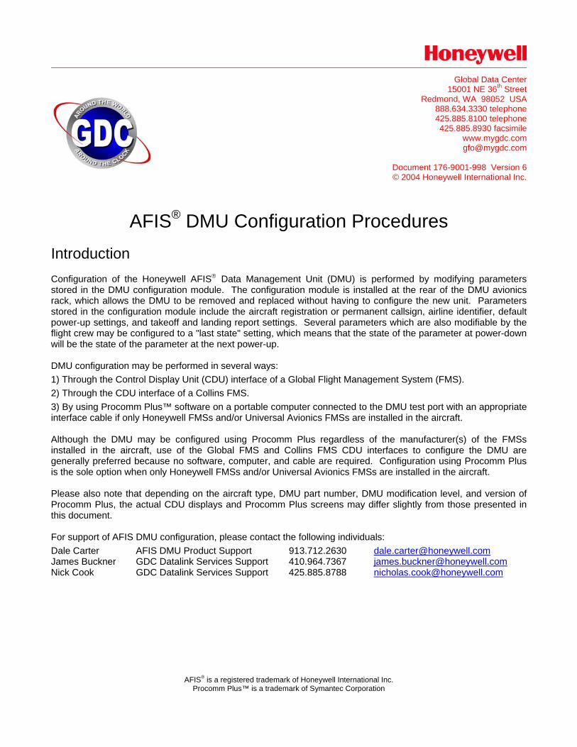
1.2 Jump pins 2 and 3 (at the 11 o'clock and 10 o'clock positions respectively) on the test port with either a test port connector or a wire. Note: The test port connector is available as Bendix/King part number 12870-1 from Bendix/King avionics dealers.
1.3 Apply power to the DMU and FMSs.
1.4 Press the AFIS function key on the CDU to access the AFIS MENU display. Note: This procedure is based on a dual GNS-XLS Enhanced FMS installation with a -0210 DMU.
AFIS MENU 1 WX GRAPHICS 2 TERMINAL WX 3 SIGMETS 4 WINDS ALOFT 5 AFIS FLT PLAN 6 RECALL AFIS FPL 7 SEND AFIS MSG 8 DISPL AFIS MSG 9 OPERATING MODES
1.5 Line select RECALL AFIS FLIGHT PLAN and then press the ENTER function key to access the RECALL AFIS FPL display. Line select the DATE field and enter 357777.
RECALL AFIS FPL FPL-# DATE 357777 ETD FR TO
1.6 Press the ENTER function key to access the configuration displays. The three most recent configurations may be edited by pressing 1, 2, or 3 and then the ENTER function key or a new configuration based on default values may be created by pressing 4 and then the ENTER function key.
CONFIGURATION READ/CHANGE 1 CONFIGURATION OF: 1 15JUL03 2 18OCT02 3 12AUG01 4 NEW VERSION
AFIS DMU Configuration Procedures 3
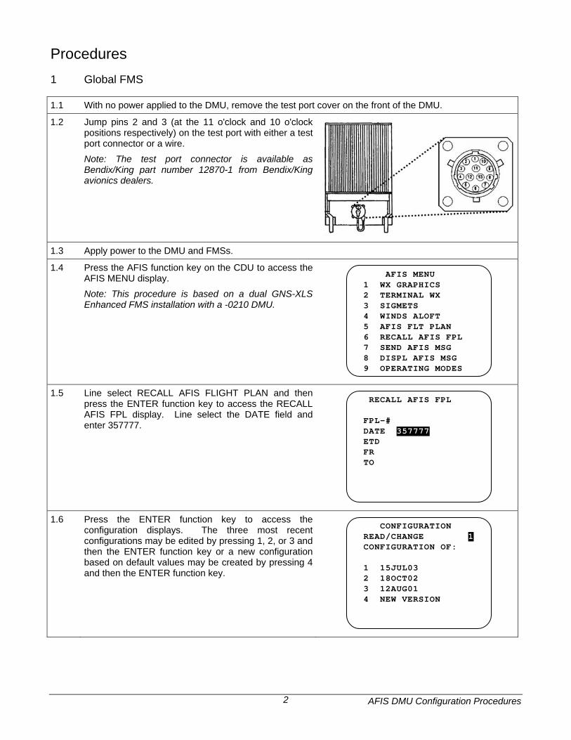
1.7 Configure the aircraft Basic Operating Weight by
entering the weight in pounds and then pressing the ENTER function key.
CONFIGURATION BASIC OPERATING WT 9355
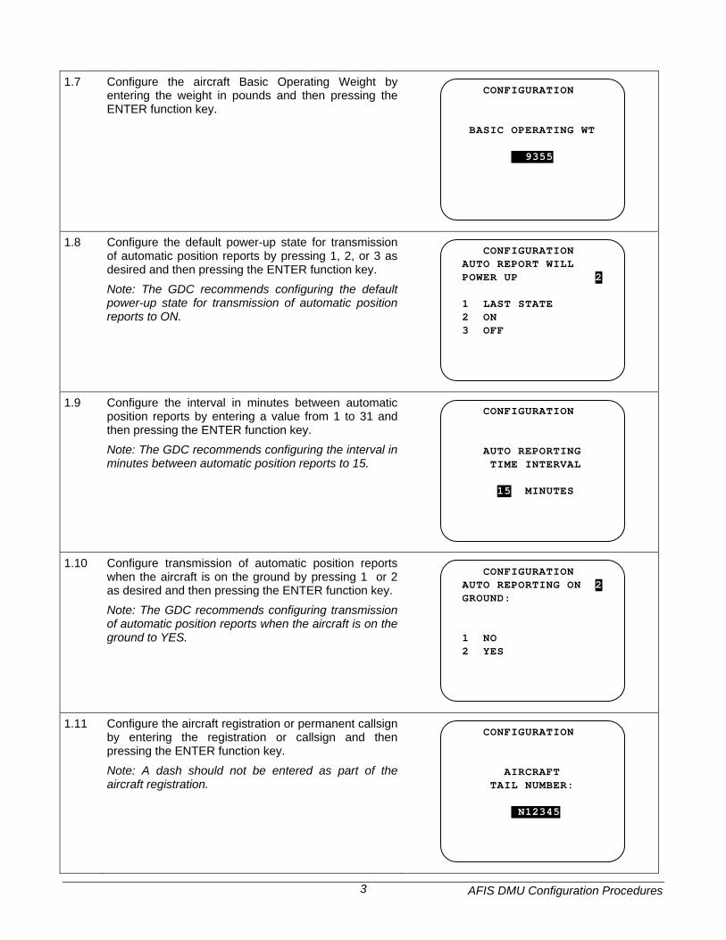
1.8 Configure the default power-up state for transmission of automatic position reports by pressing 1, 2, or 3 as desired and then pressing the ENTER function key. Note: The GDC recommends configuring the default power-up state for transmission of automatic position reports to ON.
CONFIGURATION AUTO REPORT WILL POWER UP 2 1 LAST STATE 2 ON 3 OFF
1.9 Configure the interval in minutes between automatic position reports by entering a value from 1 to 31 and then pressing the ENTER function key. Note: The GDC recommends configuring the interval in minutes between automatic position reports to 15.
CONFIGURATION AUTO REPORTING TIME INTERVAL 15 MINUTES
1.10 Configure transmission of automatic position reports when the aircraft is on the ground by pressing 1 or 2 as desired and then pressing the ENTER function key. Note: The GDC recommends configuring transmission of automatic position reports when the aircraft is on the ground to YES.
CONFIGURATION AUTO REPORTING ON 2 GROUND: 1 NO 2 YES
1.11 Configure the aircraft registration or permanent callsign by entering the registration or callsign and then pressing the ENTER function key. Note: A dash should not be entered as part of the aircraft registration.
CONFIGURATION AIRCRAFT TAIL NUMBER: n N12345
AFIS DMU Configuration Procedures 4
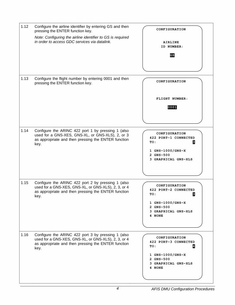
1.12 Configure the airline identifier by entering GS and then
pressing the ENTER function key. Note: Configuring the airline identifier to GS is required in order to access GDC services via datalink.
CONFIGURATION AIRLINE ID NUMBER: nGS
1.13 Configure the flight number by entering 0001 and then pressing the ENTER function key.
CONFIGURATION FLIGHT NUMBER: n0001
1.14 Configure the ARINC 422 port 1 by pressing 1 (also used for a GNS-XES, GNS-XL, or GNS-XLS), 2, or 3 as appropriate and then pressing the ENTER function key.
CONFIGURATION 422 PORT-1 CONNECTED TO: 3 1 GNS-1000/GNS-X 2 GNS-500 3 GRAPHICAL GNS-XLS
1.15 Configure the ARINC 422 port 2 by pressing 1 (also used for a GNS-XES, GNS-XL, or GNS-XLS), 2, 3, or 4 as appropriate and then pressing the ENTER function key.
CONFIGURATION 422 PORT-2 CONNECTED TO: 3 1 GNS-1000/GNS-X 2 GNS-500 3 GRAPHICAL GNS-XLS 4 NONE
1.16 Configure the ARINC 422 port 3 by pressing 1 (also used for a GNS-XES, GNS-XL, or GNS-XLS), 2, 3, or 4 as appropriate and then pressing the ENTER function key.
CONFIGURATION 422 PORT-3 CONNECTED TO: 4 1 GNS-1000/GNS-X 2 GNS-500 3 GRAPHICAL GNS-XLS 4 NONE
AFIS DMU Configuration Procedures 5
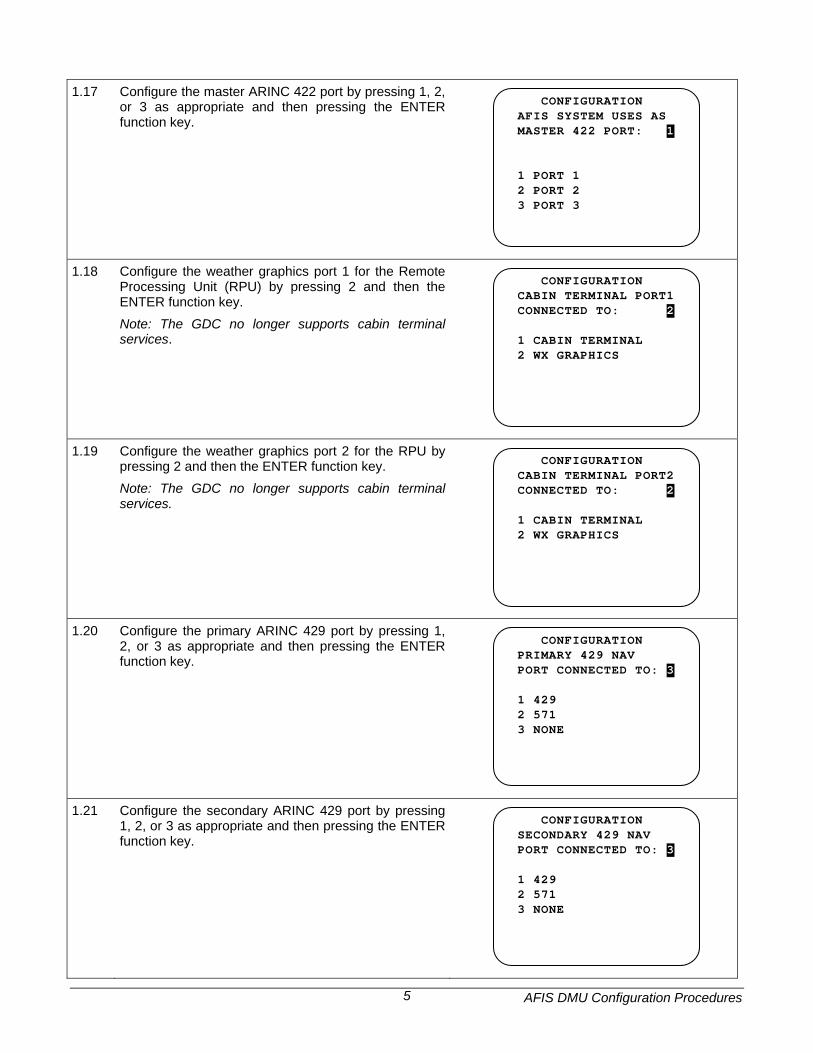
1.17 Configure the master ARINC 422 port by pressing 1, 2,
or 3 as appropriate and then pressing the ENTER function key.
CONFIGURATION AFIS SYSTEM USES AS MASTER 422 PORT: 1 1 PORT 1 2 PORT 2 3 PORT 3
1.18 Configure the weather graphics port 1 for the Remote Processing Unit (RPU) by pressing 2 and then the ENTER function key. Note: The GDC no longer supports cabin terminal services.
CONFIGURATION CABIN TERMINAL PORT1 CONNECTED TO: 2 1 CABIN TERMINAL 2 WX GRAPHICS
1.19 Configure the weather graphics port 2 for the RPU by pressing 2 and then the ENTER function key. Note: The GDC no longer supports cabin terminal services.
CONFIGURATION CABIN TERMINAL PORT2 CONNECTED TO: 2 1 CABIN TERMINAL 2 WX GRAPHICS
1.20 Configure the primary ARINC 429 port by pressing 1, 2, or 3 as appropriate and then pressing the ENTER function key.
CONFIGURATION PRIMARY 429 NAV PORT CONNECTED TO: 3 1 429 2 571 3 NONE
1.21 Configure the secondary ARINC 429 port by pressing 1, 2, or 3 as appropriate and then pressing the ENTER function key.
CONFIGURATION SECONDARY 429 NAV PORT CONNECTED TO: 3 1 429 2 571 3 NONE
AFIS DMU Configuration Procedures 6
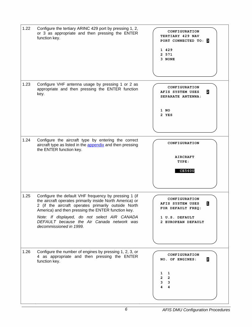
1.22 Configure the tertiary ARINC 429 port by pressing 1, 2,
or 3 as appropriate and then pressing the ENTER function key.
CONFIGURATION TERTIARY 429 NAV PORT CONNECTED TO: 3 1 429 2 571 3 NONE
1.23 Configure VHF antenna usage by pressing 1 or 2 as appropriate and then pressing the ENTER function key.
CONFIGURATION AFIS SYSTEM USES 2 SEPARATE ANTENNA: 1 NO 2 YES
1.24 Configure the aircraft type by entering the correct aircraft type as listed in the appendix and then pressing the ENTER function key.
CONFIGURATION AIRCRAFT TYPE: CE560U5
1.25 Configure the default VHF frequency by pressing 1 (if the aircraft operates primarily inside North America) or 2 (if the aircraft operates primarily outside North America) and then pressing the ENTER function key. Note: If displayed, do not select AIR CANADA DEFAULT because the Air Canada network was decommissioned in 1999.
CONFIGURATION AFIS SYSTEM USES 1 FOR DEFAULT FREQ: 1 U.S. DEFAULT 2 EUROPEAN DEFAULT
1.26 Configure the number of engines by pressing 1, 2, 3, or 4 as appropriate and then pressing the ENTER function key.
CONFIGURATION NO. OF ENGINES: 2 1 1 2 2 3 3 4 4
AFIS DMU Configuration Procedures 7
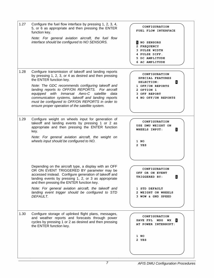
1.27 Configure the fuel flow interface by pressing 1, 2, 3, 4,
5, or 6 as appropriate and then pressing the ENTER function key. Note: For general aviation aircraft, the fuel flow interface should be configured to NO SENSORS.
CONFIGURATION FUEL FLOW INTERFACE 1 NO SENSORS 2 FREQUENCY 3 PULSE WIDTH 4 PULSE DIFF. 5 DC AMPLITUDE 6 AC AMPLITUDE
1.28 Configure transmission of takeoff and landing reports by pressing 1, 2, 3, or 4 as desired and then pressing the ENTER function key. Note: The GDC recommends configuring takeoff and landing reports to OFF/ON REPORTS. For aircraft equipped with Inmarsat Aero-C satellite data communication systems, takeoff and landing reports must be configured to OFF/ON REPORTS in order to ensure proper operation of the satellite system.
CONFIGURATION SPECIAL FEATURES SELECTION: 1 1 OFF/ON REPORTS 2 OPTION 1 3 OFF REPORT 4 NO OFF/ON REPORTS
1.29 Configure weight on wheels input for generation of takeoff and landing events by pressing 1 or 2 as appropriate and then pressing the ENTER function key. Note: For general aviation aircraft, the weight on wheels input should be configured to NO.
CONFIGURATION USE DMU WEIGHT ON WHEELS INPUT: 1 1 NO 2 YES
Depending on the aircraft type, a display with an OFF OR ON EVENT TRIGGERED BY parameter may be accessed instead. Configure generation of takeoff and landing events by pressing 1, 2, or 3 as appropriate and then pressing the ENTER function key. Note: For general aviation aircraft, the takeoff and landing event trigger should be configured to STD DEFAULT.
CONFIGURATION OFF OR ON EVENT TRIGGERED BY: 1 1 STD DEFAULT 2 WEIGHT ON WHEELS 3 WOW & GND SPEED
1.30 Configure storage of uplinked flight plans, messages, and weather reports and forecasts through power cycles by pressing 1 or 2 as desired and then pressing the ENTER function key.
CONFIGURATION SAVE FPL MSG WX 1 AT POWER INTERRUPT: 1 NO 2 YES
AFIS DMU Configuration Procedures 8
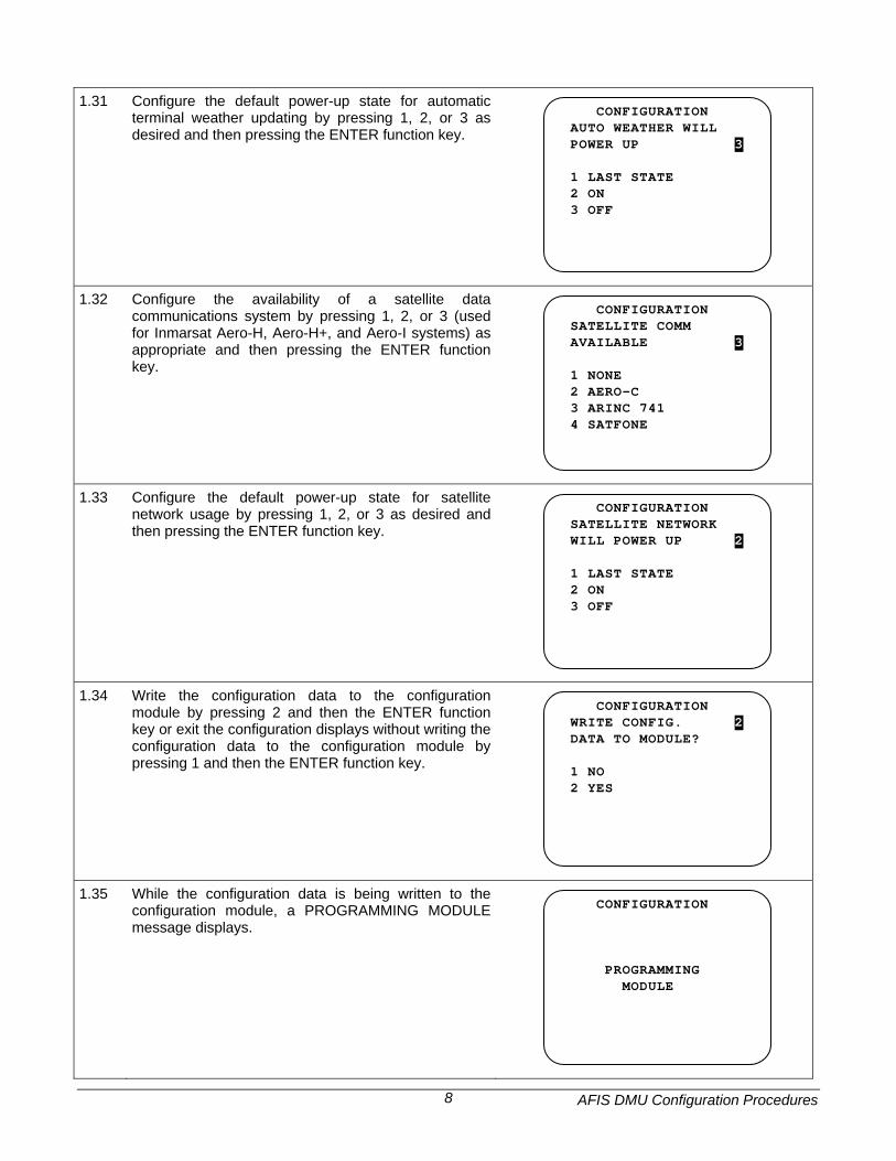
1.31 Configure the default power-up state for automatic
terminal weather updating by pressing 1, 2, or 3 as desired and then pressing the ENTER function key.
CONFIGURATION AUTO WEATHER WILL POWER UP 3 1 LAST STATE 2 ON 3 OFF
1.32 Configure the availability of a satellite data communications system by pressing 1, 2, or 3 (used for Inmarsat Aero-H, Aero-H+, and Aero-I systems) as appropriate and then pressing the ENTER function key.
CONFIGURATION SATELLITE COMM AVAILABLE 3 1 NONE 2 AERO-C 3 ARINC 741 4 SATFONE
1.33 Configure the default power-up state for satellite network usage by pressing 1, 2, or 3 as desired and then pressing the ENTER function key.
CONFIGURATION SATELLITE NETWORK WILL POWER UP 2 1 LAST STATE 2 ON 3 OFF
1.34 Write the configuration data to the configuration module by pressing 2 and then the ENTER function key or exit the configuration displays without writing the configuration data to the configuration module by pressing 1 and then the ENTER function key.
CONFIGURATION WRITE CONFIG. 2 DATA TO MODULE? 1 NO 2 YES
1.35 While the configuration data is being written to the configuration module, a PROGRAMMING MODULE message displays.
CONFIGURATION PROGRAMMING MODULE
AFIS DMU Configuration Procedures 9
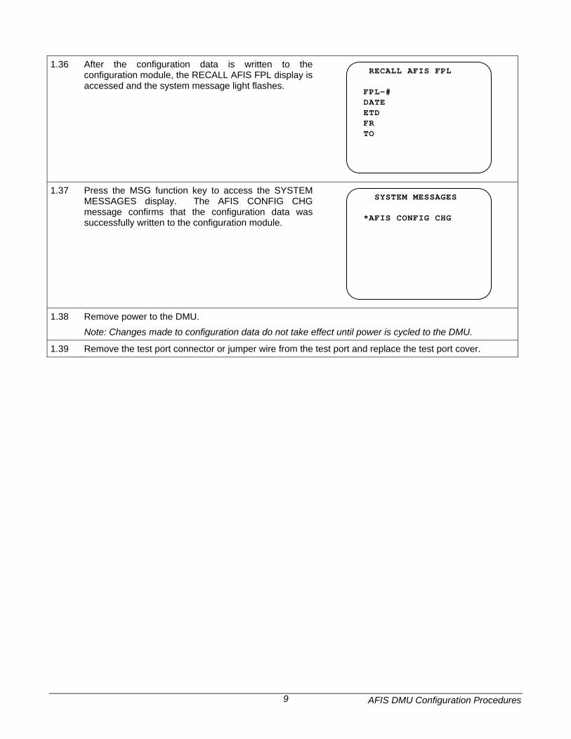
1.36 After the configuration data is written to the
configuration module, the RECALL AFIS FPL display is accessed and the system message light flashes.
RECALL AFIS FPL FPL-# DATE ETD FR TO
1.37 Press the MSG function key to access the SYSTEM MESSAGES display. The AFIS CONFIG CHG message confirms that the configuration data was successfully written to the configuration module.
SYSTEM MESSAGES *AFIS CONFIG CHG
1.38 Remove power to the DMU. Note: Changes made to configuration data do not take effect until power is cycled to the DMU.
1.39 Remove the test port connector or jumper wire from the test port and replace the test port cover.
AFIS DMU Configuration Procedures 10
2 Collins FMS 2.1 With no power applied to the DMU, remove the test port cover on the front of the DMU.
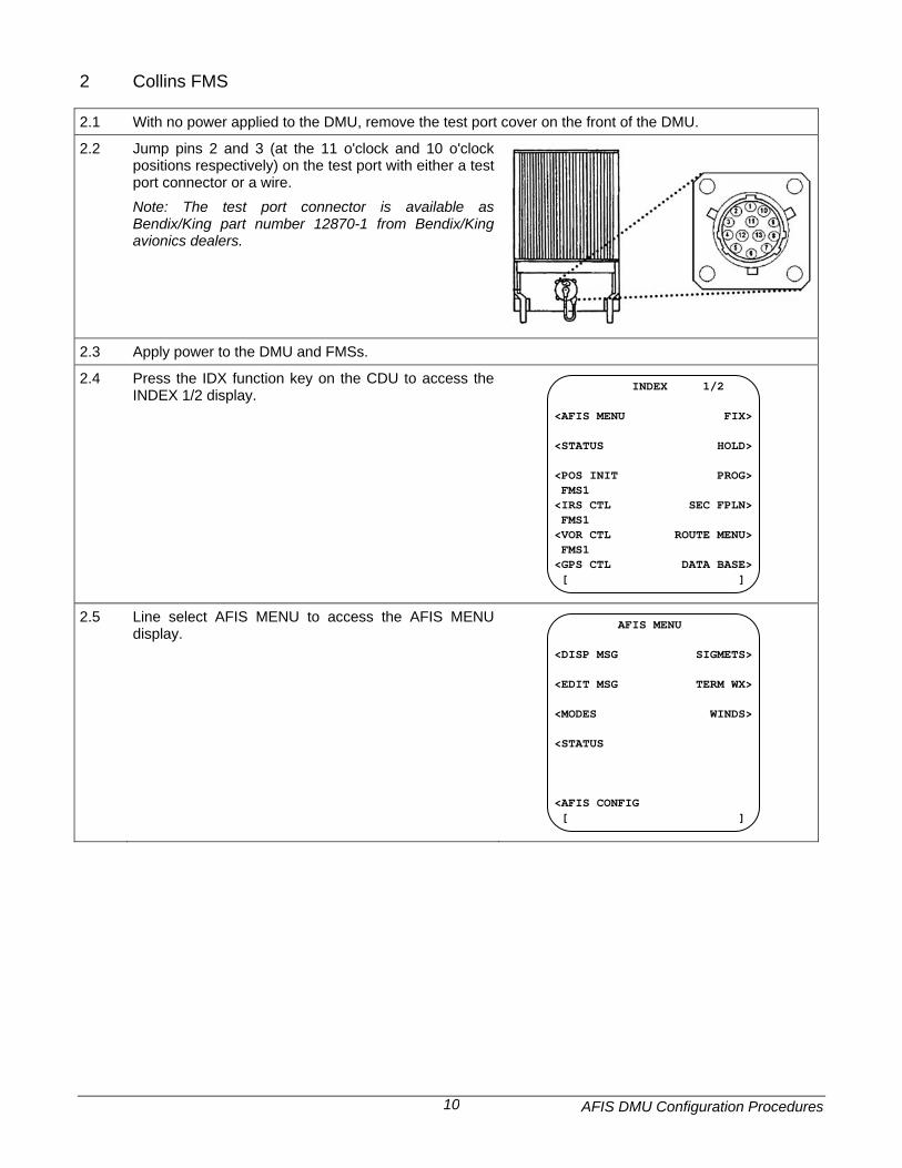
2.2 Jump pins 2 and 3 (at the 11 o'clock and 10 o'clock positions respectively) on the test port with either a test port connector or a wire. Note: The test port connector is available as Bendix/King part number 12870-1 from Bendix/King avionics dealers.
2.3 Apply power to the DMU and FMSs.
2.4 Press the IDX function key on the CDU to access the INDEX 1/2 display.
INDEX 1/2 <AFIS MENU FIX> <STATUS HOLD> <POS INIT PROG> FMS1 <IRS CTL SEC FPLN> FMS1 <VOR CTL ROUTE MENU> FMS1 <GPS CTL DATA BASE> [ ]
2.5 Line select AFIS MENU to access the AFIS MENU display.
AFIS MENU <DISP MSG SIGMETS> <EDIT MSG TERM WX> <MODES WINDS> <STATUS <AFIS CONFIG [ ]
AFIS DMU Configuration Procedures 11
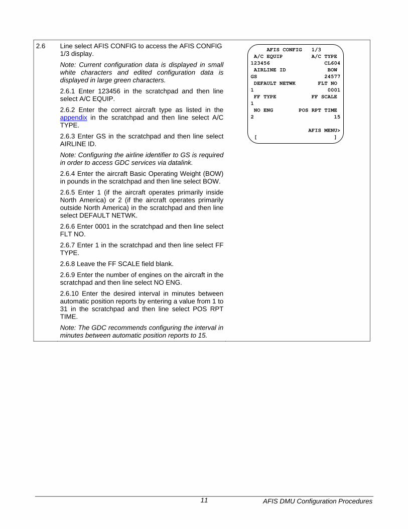
2.6 Line select AFIS CONFIG to access the AFIS CONFIG
1/3 display. Note: Current configuration data is displayed in small white characters and edited configuration data is displayed in large green characters. 2.6.1 Enter 123456 in the scratchpad and then line select A/C EQUIP. 2.6.2 Enter the correct aircraft type as listed in the appendix in the scratchpad and then line select A/C TYPE. 2.6.3 Enter GS in the scratchpad and then line select AIRLINE ID. Note: Configuring the airline identifier to GS is required in order to access GDC services via datalink. 2.6.4 Enter the aircraft Basic Operating Weight (BOW) in pounds in the scratchpad and then line select BOW. 2.6.5 Enter 1 (if the aircraft operates primarily inside North America) or 2 (if the aircraft operates primarily outside North America) in the scratchpad and then line select DEFAULT NETWK. 2.6.6 Enter 0001 in the scratchpad and then line select FLT NO. 2.6.7 Enter 1 in the scratchpad and then line select FF TYPE. 2.6.8 Leave the FF SCALE field blank. 2.6.9 Enter the number of engines on the aircraft in the scratchpad and then line select NO ENG. 2.6.10 Enter the desired interval in minutes between automatic position reports by entering a value from 1 to 31 in the scratchpad and then line select POS RPT TIME. Note: The GDC recommends configuring the interval in minutes between automatic position reports to 15.
AFIS CONFIG 1/3 A/C EQUIP A/C TYPE 123456 CL604 AIRLINE ID BOW GS 24577 DEFAULT NETWK FLT NO 1 0001 FF TYPE FF SCALE 1 NO ENG POS RPT TIME 2 15 AFIS MENU> [ ]
AFIS DMU Configuration Procedures 12
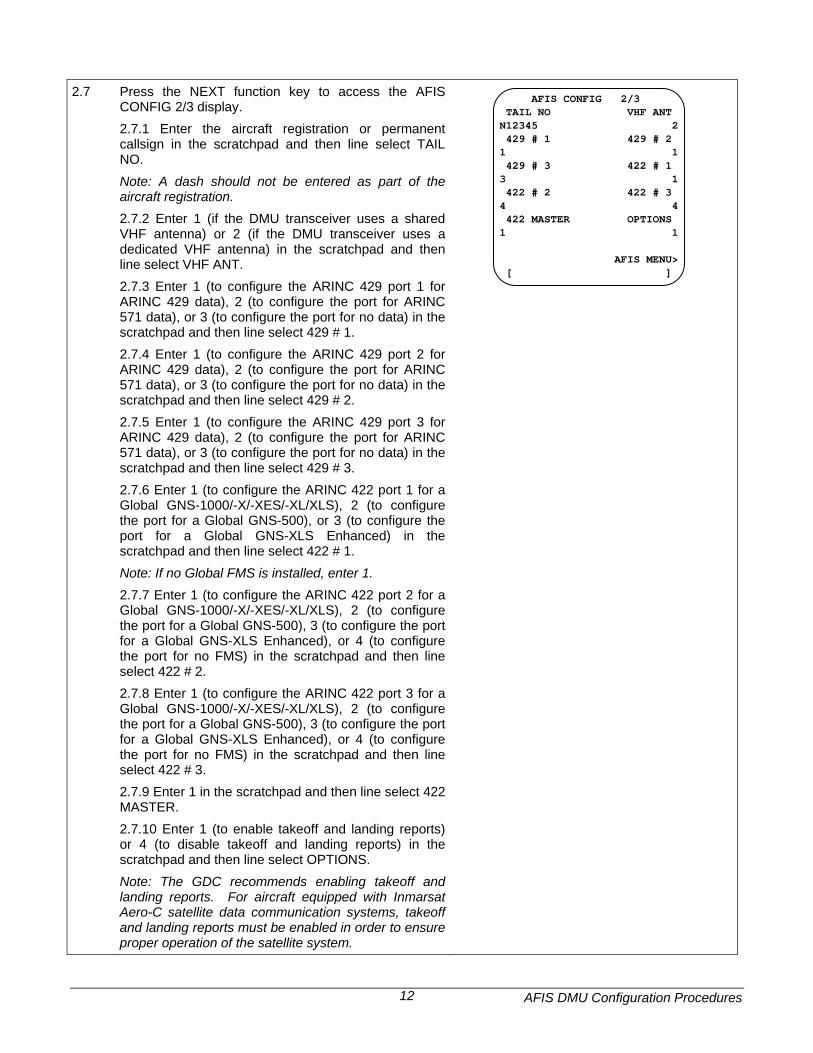
2.7 Press the NEXT function key to access the AFIS
CONFIG 2/3 display. 2.7.1 Enter the aircraft registration or permanent callsign in the scratchpad and then line select TAIL NO. Note: A dash should not be entered as part of the aircraft registration. 2.7.2 Enter 1 (if the DMU transceiver uses a shared VHF antenna) or 2 (if the DMU transceiver uses a dedicated VHF antenna) in the scratchpad and then line select VHF ANT. 2.7.3 Enter 1 (to configure the ARINC 429 port 1 for ARINC 429 data), 2 (to configure the port for ARINC 571 data), or 3 (to configure the port for no data) in the scratchpad and then line select 429 # 1. 2.7.4 Enter 1 (to configure the ARINC 429 port 2 for ARINC 429 data), 2 (to configure the port for ARINC 571 data), or 3 (to configure the port for no data) in the scratchpad and then line select 429 # 2. 2.7.5 Enter 1 (to configure the ARINC 429 port 3 for ARINC 429 data), 2 (to configure the port for ARINC 571 data), or 3 (to configure the port for no data) in the scratchpad and then line select 429 # 3. 2.7.6 Enter 1 (to configure the ARINC 422 port 1 for a Global GNS-1000/-X/-XES/-XL/XLS), 2 (to configure the port for a Global GNS-500), or 3 (to configure the port for a Global GNS-XLS Enhanced) in the scratchpad and then line select 422 # 1. Note: If no Global FMS is installed, enter 1. 2.7.7 Enter 1 (to configure the ARINC 422 port 2 for a Global GNS-1000/-X/-XES/-XL/XLS), 2 (to configure the port for a Global GNS-500), 3 (to configure the port for a Global GNS-XLS Enhanced), or 4 (to configure the port for no FMS) in the scratchpad and then line select 422 # 2. 2.7.8 Enter 1 (to configure the ARINC 422 port 3 for a Global GNS-1000/-X/-XES/-XL/XLS), 2 (to configure the port for a Global GNS-500), 3 (to configure the port for a Global GNS-XLS Enhanced), or 4 (to configure the port for no FMS) in the scratchpad and then line select 422 # 3. 2.7.9 Enter 1 in the scratchpad and then line select 422 MASTER. 2.7.10 Enter 1 (to enable takeoff and landing reports) or 4 (to disable takeoff and landing reports) in the scratchpad and then line select OPTIONS. Note: The GDC recommends enabling takeoff and landing reports. For aircraft equipped with Inmarsat Aero-C satellite data communication systems, takeoff and landing reports must be enabled in order to ensure proper operation of the satellite system.
AFIS CONFIG 2/3 TAIL NO VHF ANT N12345 2 429 # 1 429 # 2 1 1 429 # 3 422 # 1 3 1 422 # 2 422 # 3 4 4 422 MASTER OPTIONS 1 1 AFIS MENU> [ ]
AFIS DMU Configuration Procedures 13
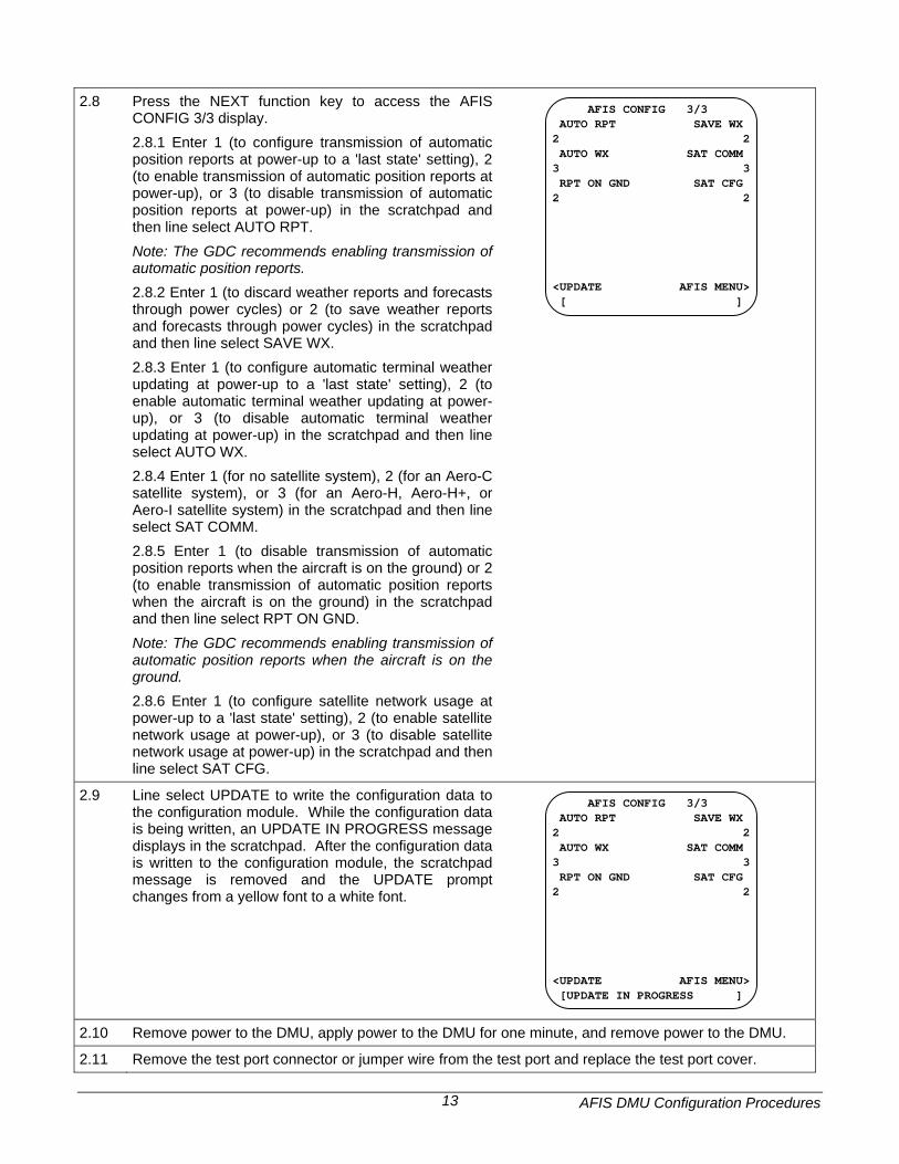
2.8 Press the NEXT function key to access the AFIS
CONFIG 3/3 display. 2.8.1 Enter 1 (to configure transmission of automatic position reports at power-up to a 'last state' setting), 2 (to enable transmission of automatic position reports at power-up), or 3 (to disable transmission of automatic position reports at power-up) in the scratchpad and then line select AUTO RPT. Note: The GDC recommends enabling transmission of automatic position reports. 2.8.2 Enter 1 (to discard weather reports and forecasts through power cycles) or 2 (to save weather reports and forecasts through power cycles) in the scratchpad and then line select SAVE WX. 2.8.3 Enter 1 (to configure automatic terminal weather updating at power-up to a 'last state' setting), 2 (to enable automatic terminal weather updating at power-up), or 3 (to disable automatic terminal weather updating at power-up) in the scratchpad and then line select AUTO WX. 2.8.4 Enter 1 (for no satellite system), 2 (for an Aero-C satellite system), or 3 (for an Aero-H, Aero-H+, or Aero-I satellite system) in the scratchpad and then line select SAT COMM. 2.8.5 Enter 1 (to disable transmission of automatic position reports when the aircraft is on the ground) or 2 (to enable transmission of automatic position reports when the aircraft is on the ground) in the scratchpad and then line select RPT ON GND. Note: The GDC recommends enabling transmission of automatic position reports when the aircraft is on the ground. 2.8.6 Enter 1 (to configure satellite network usage at power-up to a 'last state' setting), 2 (to enable satellite network usage at power-up), or 3 (to disable satellite network usage at power-up) in the scratchpad and then line select SAT CFG.
AFIS CONFIG 3/3 AUTO RPT SAVE WX 2 2 AUTO WX SAT COMM 3 3 RPT ON GND SAT CFG 2 2 <UPDATE AFIS MENU> [ ]
2.9 Line select UPDATE to write the configuration data to the configuration module. While the configuration data is being written, an UPDATE IN PROGRESS message displays in the scratchpad. After the configuration data is written to the configuration module, the scratchpad message is removed and the UPDATE prompt changes from a yellow font to a white font.
AFIS CONFIG 3/3 AUTO RPT SAVE WX 2 2 AUTO WX SAT COMM 3 3 RPT ON GND SAT CFG 2 2 <UPDATE AFIS MENU> [UPDATE IN PROGRESS ]
2.10 Remove power to the DMU, apply power to the DMU for one minute, and remove power to the DMU.
2.11 Remove the test port connector or jumper wire from the test port and replace the test port cover.
AFIS DMU Configuration Procedures 14
3 Procomm Plus 3.1 If not already accomplished, install Procomm Plus on a portable personal computer (PC).
Note: Procomm Plus is available either directly from Symantec Corporation at www.symantec.com or from various computer software retail stores. Note: This procedure is based on Procomm Plus 4.8.
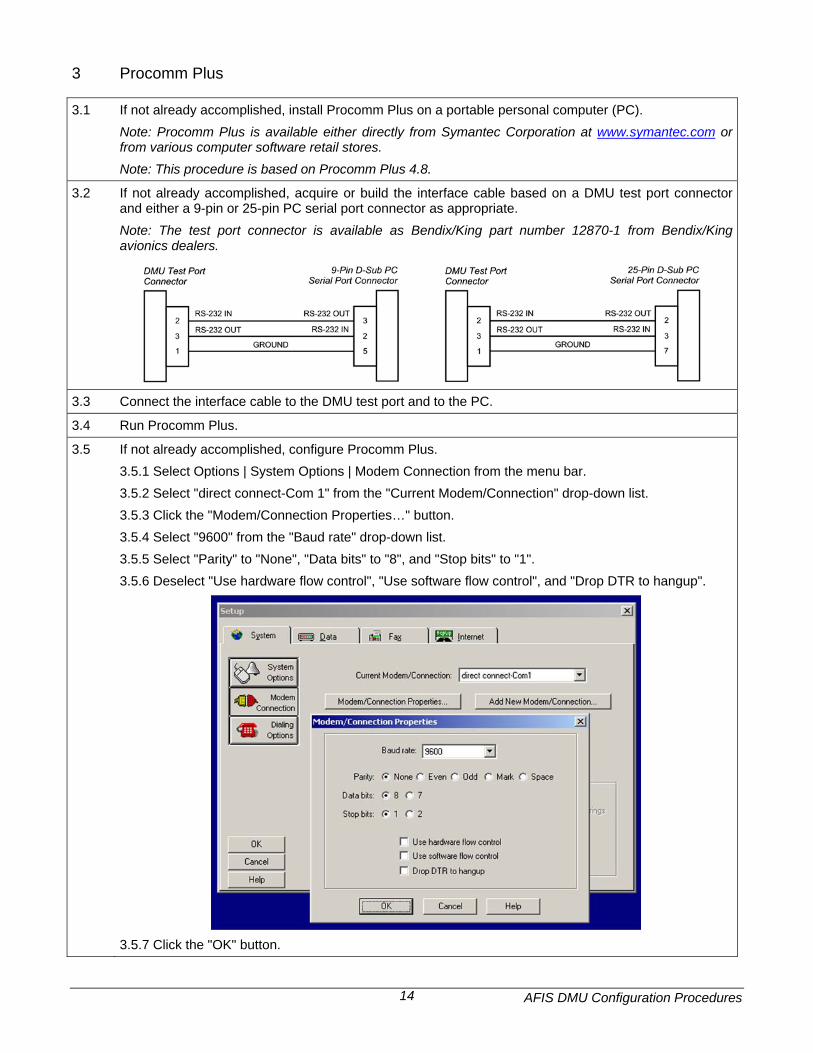
3.2 If not already accomplished, acquire or build the interface cable based on a DMU test port connector and either a 9-pin or 25-pin PC serial port connector as appropriate. Note: The test port connector is available as Bendix/King part number 12870-1 from Bendix/King avionics dealers.
3.3 Connect the interface cable to the DMU test port and to the PC.
3.4 Run Procomm Plus.
3.5 If not already accomplished, configure Procomm Plus. 3.5.1 Select Options | System Options | Modem Connection from the menu bar. 3.5.2 Select "direct connect-Com 1" from the "Current Modem/Connection" drop-down list. 3.5.3 Click the "Modem/Connection Properties…" button. 3.5.4 Select "9600" from the "Baud rate" drop-down list. 3.5.5 Select "Parity" to "None", "Data bits" to "8", and "Stop bits" to "1". 3.5.6 Deselect "Use hardware flow control", "Use software flow control", and "Drop DTR to hangup".
3.5.7 Click the "OK" button.
AFIS DMU Configuration Procedures 15
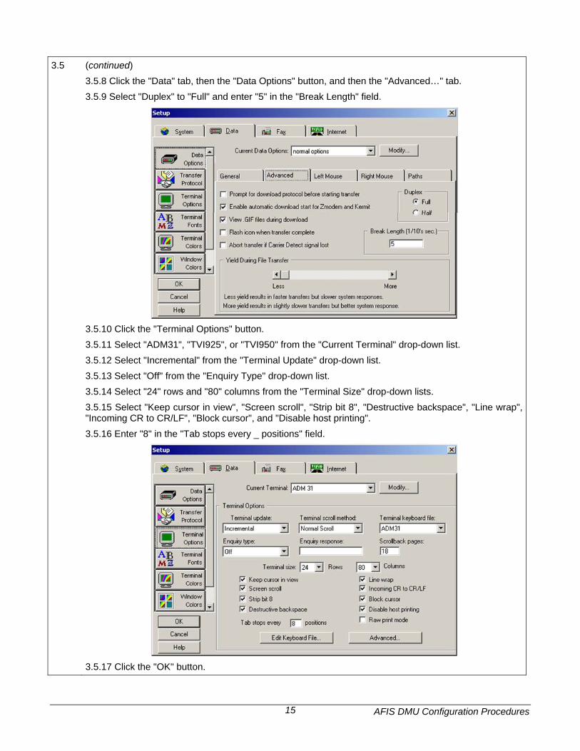
3.5 (continued)
3.5.8 Click the "Data" tab, then the "Data Options" button, and then the "Advanced…" tab. 3.5.9 Select "Duplex" to "Full" and enter "5" in the "Break Length" field.
3.5.10 Click the "Terminal Options" button. 3.5.11 Select "ADM31", "TVI925", or "TVI950" from the "Current Terminal" drop-down list. 3.5.12 Select "Incremental" from the "Terminal Update" drop-down list. 3.5.13 Select "Off" from the "Enquiry Type" drop-down list. 3.5.14 Select "24" rows and "80" columns from the "Terminal Size" drop-down lists. 3.5.15 Select "Keep cursor in view", "Screen scroll", "Strip bit 8", "Destructive backspace", "Line wrap", "Incoming CR to CR/LF", "Block cursor", and "Disable host printing". 3.5.16 Enter "8" in the "Tab stops every _ positions" field.
3.5.17 Click the "OK" button.
AFIS DMU Configuration Procedures 16
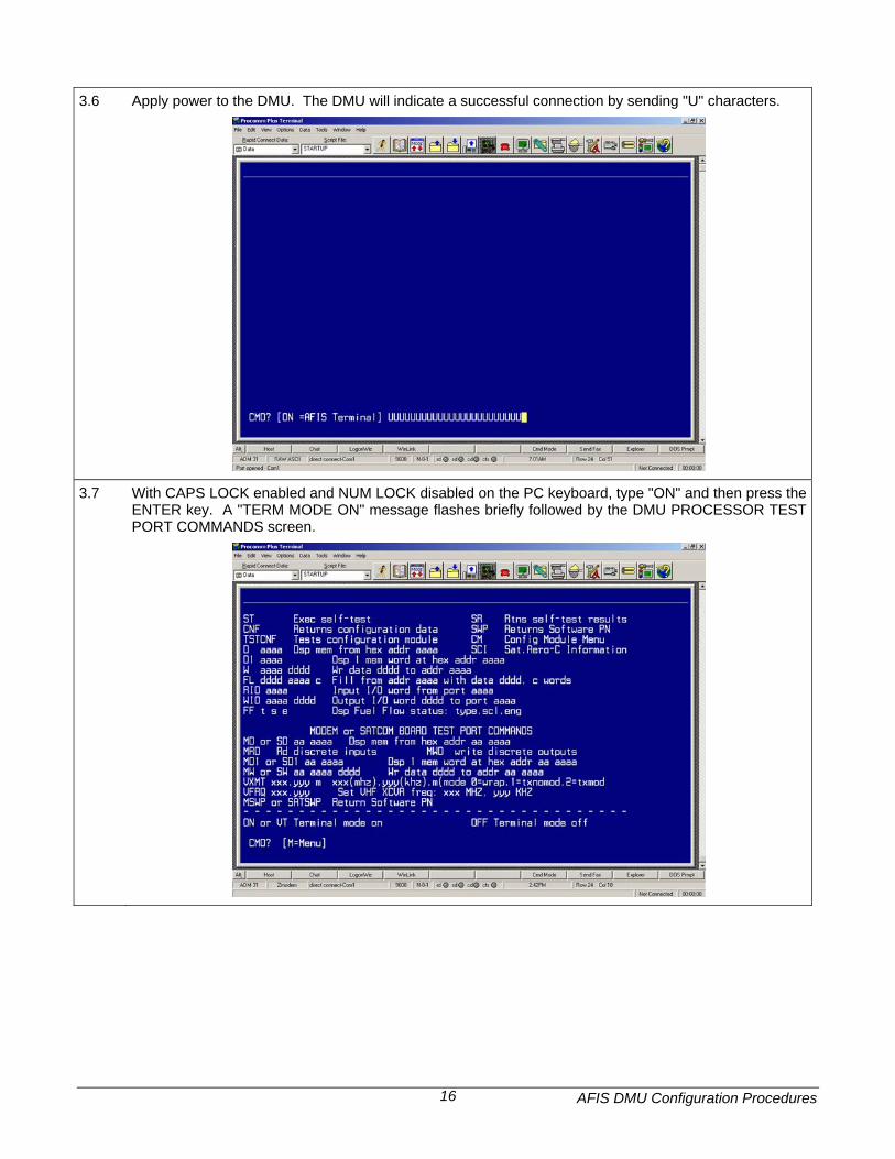
3.6 Apply power to the DMU. The DMU will indicate a successful connection by sending "U" characters.
3.7 With CAPS LOCK enabled and NUM LOCK disabled on the PC keyboard, type "ON" and then press the ENTER key. A "TERM MODE ON" message flashes briefly followed by the DMU PROCESSOR TEST PORT COMMANDS screen.
AFIS DMU Configuration Procedures 17
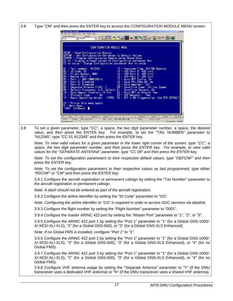
3.8 Type "CM" and then press the ENTER key to access the CONFIGURATION MODULE MENU screen.
3.9 To set a given parameter, type "CC", a space, the two digit parameter number, a space, the desired value, and then press the ENTER key. For example, to set the "TAIL NUMBER" parameter to "N12345", type "CC 01 N12345" and then press the ENTER key. Note: To view valid values for a given parameter in the lower right corner of the screen, type "CC", a space, the two digit parameter number, and then press the ENTER key. For example, to view valid values for the "SEPARATE ANTENNA" parameter, type "CC 08" and then press the ENTER key. Note: To set the configuration parameters to their respective default values, type "DEFCNF" and then press the ENTER key. Note: To set the configuration parameters to their respective values as last programmed, type either "RDCNF" or "CM" and then press the ENTER key. 3.9.1 Configure the aircraft registration or permanent callsign by setting the "Tail Number" parameter to the aircraft registration or permanent callsign. Note: A dash should not be entered as part of the aircraft registration. 3.9.2 Configure the airline identifier by setting the "ID Code" parameter to "GS". Note: Configuring the airline identifier to "GS" is required in order to access GDC services via datalink. 3.9.3 Configure the flight number by setting the "Flight Number" parameter to "0001". 3.9.4 Configure the master ARINC 422 port by setting the "Master Port" parameter to "1", "2", or "3". 3.9.5 Configure the ARINC 422 port 1 by setting the "Port 1" parameter to "1" (for a Global GNS-1000/-X/-XES/-XL/-XLS), "2" (for a Global GNS-500), or "3" (for a Global GNS-XLS Enhanced). Note: If no Global FMS is installed, configure "Port 1" to "1". 3.9.6 Configure the ARINC 422 port 2 by setting the "Port 1" parameter to "1" (for a Global GNS-1000/-X/-XES/-XL/-XLS), "2" (for a Global GNS-500), "3" (for a Global GNS-XLS Enhanced), or "4" (for no Global FMS). 3.9.7 Configure the ARINC 422 port 3 by setting the "Port 1" parameter to "1" (for a Global GNS-1000/-X/-XES/-XL/-XLS), "2" (for a Global GNS-500), "3" (for a Global GNS-XLS Enhanced), or "4" (for no Global FMS). 3.9.8 Configure VHF antenna usage by setting the "Separate Antenna" parameter to "Y" (if the DMU transceiver uses a dedicated VHF antenna) or "N" (if the DMU transceiver uses a shared VHF antenna).
AFIS DMU Configuration Procedures 18
3.9 (continued) 3.9.9 Configure the default VHF frequency by setting the "Default Frequency Parameter" to "1" (if the aircraft operates primarily inside North America) or "2" (if the aircraft operates primarily outside North America). 3.9.10 Configure the interval in minutes between automatic position reports by setting the "Auto Report Interval" parameter to a value between 1 and 31. Note: The GDC recommends configuring the interval in minutes between automatic position reports to 15. 3.9.11 Configure the aircraft type by setting the "Aircraft Type" parameter to the aircraft type as found in the appendix. 3.9.12 Configure the aircraft Basic Operating Weight by setting the "Basic Operating Weight" parameter to the aircraft Basic Operating Weight in pounds. 3.9.13 Configure transmission of takeoff and landing reports by setting the "Features Flag" parameter to "1" (Off/On Reports) or "4" (No Off/On Reports). Note: The GDC recommends enabling takeoff and landing reports. For aircraft equipped with Inmarsat Aero-C satellite data communication systems, takeoff and landing reports must be enabled in order to ensure proper operation of the satellite system. 3.9.14 Configure the ARINC 429 port A by setting the "429 Port A" parameter to "1" (for ARINC 429 data), "2" (for ARINC 571 data), or "3" (for no data). 3.9.15 Configure the ARINC 429 port B by setting the "429 Port B" parameter to "1" (for ARINC 429 data), "2" (for ARINC 571 data), or "3" (for no data). 3.9.16 Configure the ARINC 429 port C by setting the "429 Port C" parameter to "1" (for ARINC 429 data), "2" (for ARINC 571 data), or "3" (for no data). 3.9.17 Configure the default power-up state for transmission of automatic position reports by setting the "Auto Rpt Config" parameter to 1 (Last State), 2 (On), or 3 (Off). Note: The GDC recommends configuring the default power-up state for transmission of automatic position reports to On. 3.9.18 Configure storage of uplinked flight plans, messages, and weather reports and forecasts through power cycles by setting the "Save Fpl, Msg, Wx" parameter to "1" (No) or "2" (Yes). 3.9.19 Configure the default power-up state for automatic terminal weather updating by setting the "Auto Weather" parameter to "1" (Last State), "2" (On), or "3" (Off). 3.9.20 Configure the availability of a satellite data communications system by setting the "Satellite Comm" parameter to "1" (for no system), "2" (for an Aero-C system), or "3" (for an Aero-H, Aero-H+, or Aero-I system). 3.9.21 Configure the default power-up state for satellite network usage by setting the "Satellite Network" parameter to "1" (Last State), "2" (On), or "3" (Off). Note: Some Honeywell FMSs may overwrite this parameter so that the DMU operates as if it was configured with the “last state” setting. This issue will be corrected with a future Honeywell FMS software release. 3.9.22 Configure transmission of automatic position reports when the aircraft is on the ground by setting the "Auto Rpt On Ground" parameter to "N" (No) or "Y" (Yes). Note: The GDC recommends configuring transmission of automatic position reports when the aircraft is on the ground to Yes. 3.9.23 Configure the default power-up state for VHF network usage by setting the "VHF Network" parameter to "N" (No) or "Y" (Yes). 3.9.24 Configure the triggering of takeoff and landing events by setting the "Off & On Triggered By" parameter to "1" (Use Std Default) for general aviation aircraft. Note: Depending on the aircraft type, a "Use DMU Weight On Wheels" parameter may be displayed instead. This parameter should be set to "N" (No) for general aviation aircraft.
AFIS DMU Configuration Procedures 19
3.10 To program the configuration module with the current parameters, type "PGMCNF" and then press the
ENTER key. The CONFIGURATION MODULE MENU screen will temporarily go blank as the configuration module is being programmed. Note: To exit the CONFIGURATION MODULE MENU screen without programming the configuration module with the current parameters, type "M" and then press the ENTER key to return to the DMU PROCESSOR TEST PORT COMMANDS screen.
3.11 After the configuration module has been programmed, type "M" and then press the ENTER key to return to the DMU PROCESSOR TEST PORT COMMANDS screen.
3.12 Type "OFF" and then press the ENTER key. A "TERM MODE OFF" message flashes.
3.13 Exit Procomm Plus.
3.14 Remove power to the DMU. Note: Changes made to configuration data do not take effect until power is cycled to the DMU.
3.15 Remove the test port connector or jumper wire from the test port and replace the test port cover.
AFIS DMU Configuration Procedures 20
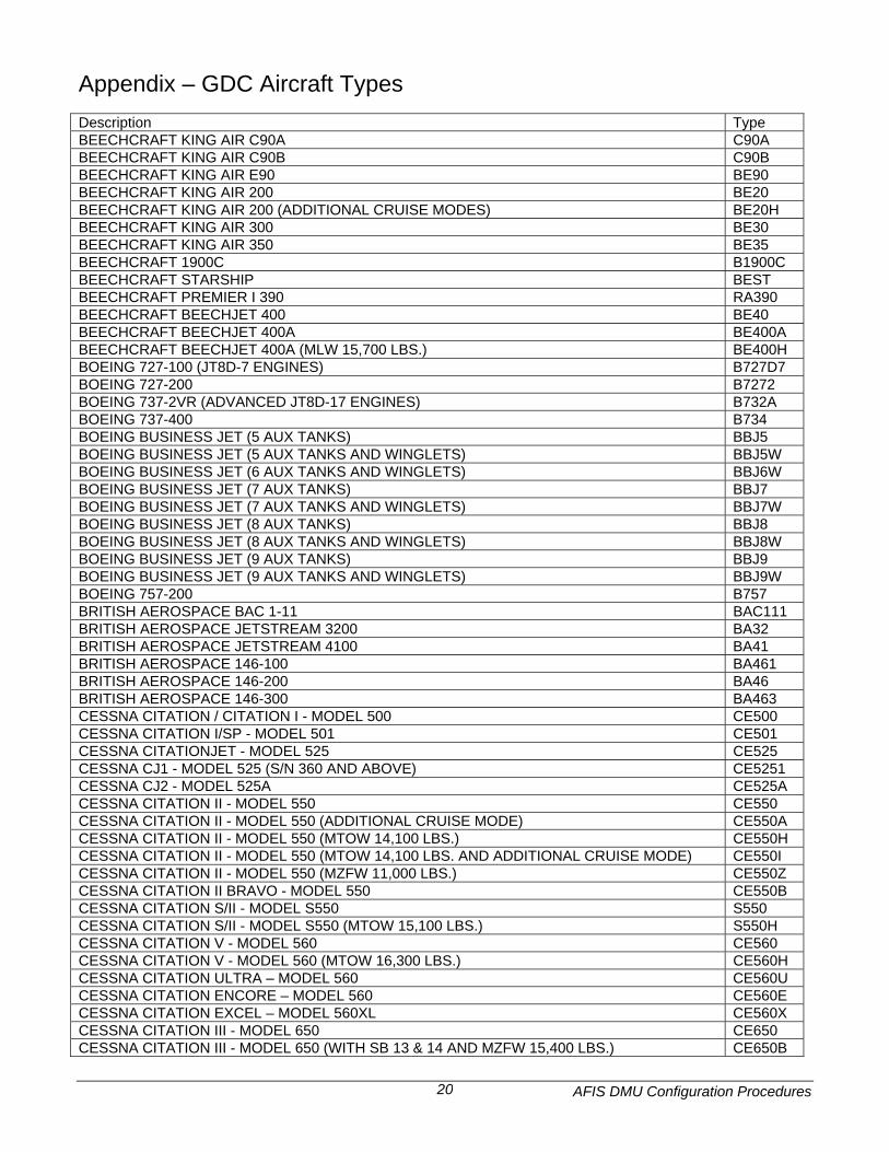
Appendix – GDC Aircraft Types Description Type BEECHCRAFT KING AIR C90A C90A BEECHCRAFT KING AIR C90B C90B BEECHCRAFT KING AIR E90 BE90 BEECHCRAFT KING AIR 200 BE20 BEECHCRAFT KING AIR 200 (ADDITIONAL CRUISE MODES) BE20H BEECHCRAFT KING AIR 300 BE30 BEECHCRAFT KING AIR 350 BE35 BEECHCRAFT 1900C B1900C BEECHCRAFT STARSHIP BEST BEECHCRAFT PREMIER I 390 RA390 BEECHCRAFT BEECHJET 400 BE40 BEECHCRAFT BEECHJET 400A BE400A BEECHCRAFT BEECHJET 400A (MLW 15,700 LBS.) BE400H BOEING 727-100 (JT8D-7 ENGINES) B727D7 BOEING 727-200 B7272 BOEING 737-2VR (ADVANCED JT8D-17 ENGINES) B732A BOEING 737-400 B734 BOEING BUSINESS JET (5 AUX TANKS) BBJ5 BOEING BUSINESS JET (5 AUX TANKS AND WINGLETS) BBJ5W BOEING BUSINESS JET (6 AUX TANKS AND WINGLETS) BBJ6W BOEING BUSINESS JET (7 AUX TANKS) BBJ7 BOEING BUSINESS JET (7 AUX TANKS AND WINGLETS) BBJ7W BOEING BUSINESS JET (8 AUX TANKS) BBJ8 BOEING BUSINESS JET (8 AUX TANKS AND WINGLETS) BBJ8W BOEING BUSINESS JET (9 AUX TANKS) BBJ9 BOEING BUSINESS JET (9 AUX TANKS AND WINGLETS) BBJ9W BOEING 757-200 B757 BRITISH AEROSPACE BAC 1-11 BAC111 BRITISH AEROSPACE JETSTREAM 3200 BA32 BRITISH AEROSPACE JETSTREAM 4100 BA41 BRITISH AEROSPACE 146-100 BA461 BRITISH AEROSPACE 146-200 BA46 BRITISH AEROSPACE 146-300 BA463 CESSNA CITATION / CITATION I - MODEL 500 CE500 CESSNA CITATION I/SP - MODEL 501 CE501 CESSNA CITATIONJET - MODEL 525 CE525 CESSNA CJ1 - MODEL 525 (S/N 360 AND ABOVE) CE5251 CESSNA CJ2 - MODEL 525A CE525A CESSNA CITATION II - MODEL 550 CE550 CESSNA CITATION II - MODEL 550 (ADDITIONAL CRUISE MODE) CE550A CESSNA CITATION II - MODEL 550 (MTOW 14,100 LBS.) CE550H CESSNA CITATION II - MODEL 550 (MTOW 14,100 LBS. AND ADDITIONAL CRUISE MODE) CE550I CESSNA CITATION II - MODEL 550 (MZFW 11,000 LBS.) CE550Z CESSNA CITATION II BRAVO - MODEL 550 CE550B CESSNA CITATION S/II - MODEL S550 S550 CESSNA CITATION S/II - MODEL S550 (MTOW 15,100 LBS.) S550H CESSNA CITATION V - MODEL 560 CE560 CESSNA CITATION V - MODEL 560 (MTOW 16,300 LBS.) CE560H CESSNA CITATION ULTRA – MODEL 560 CE560U CESSNA CITATION ENCORE – MODEL 560 CE560E CESSNA CITATION EXCEL – MODEL 560XL CE560X CESSNA CITATION III - MODEL 650 CE650 CESSNA CITATION III - MODEL 650 (WITH SB 13 & 14 AND MZFW 15,400 LBS.) CE650B
AFIS DMU Configuration Procedures 21
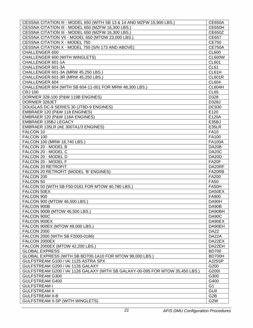
CESSNA CITATION III - MODEL 650 (WITH SB 13 & 14 AND MZFW 15,900 LBS.) CE650A CESSNA CITATION III - MODEL 650 (MZFW 16,300 LBS.) CE650H CESSNA CITATION III - MODEL 650 (MZFW 16,300 LBS.) CE650Z CESSNA CITATION VII - MODEL 650 (MTOW 23,000 LBS.) CE657 CESSNA CITATION X - MODEL 750 CE750 CESSNA CITATION X - MODEL 750 (S/N 173 AND ABOVE) CE750A CHALLENGER 600 CL600 CHALLENGER 600 (WITH WINGLETS) CL600W CHALLENGER 601-1A CL601 CHALLENGER 601-3A CL61 CHALLENGER 601-3A (MRW 45,250 LBS.) CL61H CHALLENGER 601-3R (MRW 45,250 LBS.) CL601R CHALLENGER 604 CL604 CHALLENGER 604 (WITH SB 604-11-001 FOR MRW 48,300 LBS.) CL604H CRJ 100 CL65 DORNIER 328-100 (P&W 119B ENGINES) D328 DORNIER 328JET D328J DOUGLAS DC-9 SERIES 30 (JT8D-9 ENGINES) DC930 EMBRAER 120 (P&W 118 ENGINES) E120 EMBRAER 120 (P&W 118A ENGINES) E120A EMBRAER 135BJ LEGACY E35BJ EMBRAER 135LR (AE 3007A1/3 ENGINES) E35LR FALCON 10 FA10 FALCON 100 FA100 FALCON 100 (MRW 18,740 LBS.) FA100A FALCON 20 - MODEL B DA20B FALCON 20 - MODEL C DA20C FALCON 20 - MODEL D DA20D FALCON 20 - MODEL F FA20F FALCON 20 RETROFIT DA20RF FALCON 20 RETROFIT (MODEL 'B' ENGINES) FA20RB FALCON 200 FA200 FALCON 50 FA50 FALCON 50 (WITH SB F50-0161 FOR MTOW 40,780 LBS.) FA50H FALCON 50EX DA50EX FALCON 900 FA900 FALCON 900 (MTOW 46,500 LBS.) DA90H FALCON 900B DA90B FALCON 900B (MTOW 46,500 LBS.) DA90BH FALCON 900C DA90C FALCON 900EX DA90EX FALCON 900EX (MTOW 49,000 LBS.) DA90EH FALCON 2000 DA22 FALCON 2000 (WITH SB F2000-0186) DA22A FALCON 2000EX DA22EX FALCON 2000EX (MTOW 42,200 LBS.) DA22EH GLOBAL EXPRESS BD700 GLOBAL EXPRESS (WITH SB BD700-1A10 FOR MTOW 98,000 LBS.) BD700H GULFSTREAM G100 / IAI 1125 ASTRA SPX AJ25SP GULFSTREAM G200 / IAI 1126 GALAXY G200 GULFSTREAM G200 / IAI 1126 GALAXY (WITH SB GALAXY-00-095 FOR MTOW 35,450 LBS.) G200I GULFSTREAM G300 G300 GULFSTREAM G400 G400 GULFSTREAM I G1 GULFSTREAM II GUII GULFSTREAM II-B G2B GULFSTREAM II-SP (WITH WINGLETS) G2W
AFIS DMU Configuration Procedures 22
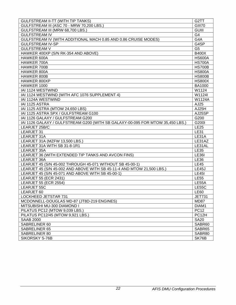
GULFSTREAM II-TT (WITH TIP TANKS) G2TT GULFSTREAM III (ASC 70 - MRW 70,200 LBS.) GIII70 GULFSTREAM III (MRW 68,700 LBS.) GUIII GULFSTREAM IV G4 GULFSTREAM IV (WITH ADDITIONAL MACH 0.85 AND 0.86 CRUISE MODES) G4A GULFSTREAM IV-SP G4SP GULFSTREAM V G5 HAWKER 400XP (S/N RK-354 AND ABOVE) B400X HAWKER 600A HS600A HAWKER 700A HS700A HAWKER 700B HS700B HAWKER 800A HS800A HAWKER 800B HS800B HAWKER 800XP HS800X HAWKER 1000 BA1000 IAI 1124 WESTWIND W1124 IAI 1124 WESTWIND (WITH AFC 1076 SUPPLEMENT 4) W1124I IAI 1124A WESTWIND W1124A IAI 1125 ASTRA AJ25 IAI 1125 ASTRA (MTOW 24,650 LBS) AJ25H IAI 1125 ASTRA SPX / GULFSTREAM G100 AJ25SP IAI 1126 GALAXY / GULFSTREAM G200 G200 IAI 1126 GALAXY / GULFSTREAM G200 (WITH SB GALAXY-00-095 FOR MTOW 35,450 LBS.) G200I LEARJET 25B/C LE25 LEARJET 31 LE31 LEARJET 31A LE31A LEARJET 31A (MZFW 13,500 LBS.) LE31AZ LEARJET 31A WITH SB 31-8-1R1 LE31AL LEARJET 35A LE35 LEARJET 36 (WITH EXTENDED TIP TANKS AND AVCON FINS) LE36I LEARJET 36A LE36 LEARJET 45 (S/N 45-002 THROUGH 45-071 WITHOUT SB 45-00-1) LE45 LEARJET 45 (S/N 45-002 AND ABOVE WITH SB 45-11-4 AND MTOW 21,500 LBS.) LE45J LEARJET 45 (S/N 45-071 AND ABOVE WITH SB 45-00-1) LE45I LEARJET 55 (ECR 2431) LE55 LEARJET 55 (ECR 2554) LE55A LEARJET 55C LE55C LEARJET 60 LE60 LOCKHEED JETSTAR 731 JET731 MCDONNELL-DOUGLAS MD-87 (JT8D-219 ENGINES) MD87 MITSUBISHI MU-300 DIAMOND I DIAM1 PILATUS PC12 (MTOW 9,039 LBS.) PC12 PILATUS PC12/45 (MTOW 9,921 LBS.) PC12H SAAB 2000 SA20 SABRELINER 60 SABR60 SABRELINER 65 SABR65 SABRELINER 80 SABR80 SIKORSKY S-76B SK76B