Embed Size (px)
Citation preview
AFRL-VA-WP-TP-2003-338 AUTOMATIC AIR COLLISION AVOIDANCE SYSTEM - DESIGN & DEVELOPMENT D.E. Swihart B.T. Nguyen A.F. Barfield E.M. Griffin
OCTOBER 2003
This material is declared a work of the U.S. Government and is not subject to copyright protection in the United States.
AIR VEHICLES DIRECTORATE AIR FORCE RESEARCH LABORATORY AIR FORCE MATERIEL COMMAND WRIGHT-PATTERSON AIR FORCE BASE, OH 45433-7542
Approved for public release; distribution is unlimited.

i
QREPORT DOCUMENTATION PAGE Form Approved OMB No. 0704-0188
The public reporting burden for this collection of information is estimated to average 1 hour per response, including the time for reviewing instructions, searching existing data sources, searching existing data sources, gathering and maintaining the data needed, and completing and reviewing the collection of information. Send comments regarding this burden estimate or any other aspect of this collection of information, including suggestions for reducing this burden, to Department of Defense, Washington Headquarters Services, Directorate for Information Operations and Reports (0704-0188), 1215 Jefferson Davis Highway, Suite 1204, Arlington, VA 22202-4302. Respondents should be aware that notwithstanding any other provision of law, no person shall be subject to any penalty for failing to comply with a collection of information if it does not display a currently valid OMB control number. PLEASE DO NOT RETURN YOUR FORM TO THE ABOVE ADDRESS.
1. REPORT DATE (DD-MM-YY)
October 2003
2. REPORT TYPE
Conference Paper Preprint 3. DATES COVERED (From - To)
5a. CONTRACT NUMBER IN-HOUSE
5b. GRANT NUMBER
4. TITLE AND SUBTITLE
AUTOMATIC AIR COLLISION AVOIDANCE SYSTEM - DESIGN & DEVELOPMENT
5c. PROGRAM ELEMENT NUMBER N/A
5d. PROJECT NUMBER
N/A 5e. TASK NUMBER
N/A
6. AUTHOR(S)
D.E. Swihart and B.T. Nguyen (AFRL/VACC) A.F. Barfield (Veridian Engineering) E.M. Griffin (Lockheed Martin Aeronautics)
5f. WORK UNIT NUMBER
N/A 7. PERFORMING ORGANIZATION NAME(S) AND ADDRESS(ES)
Control Systems Development and Application Branch (AFRL/VACC) Control Sciences Division Air Vehicles Directorate Air Force Research Laboratory, Air Force Materiel Command Wright-Patterson Air Force Base, OH 45433-7542
Veridian Engineering Lockheed Martin Aeronautics
8. PERFORMING ORGANIZATION REPORT NUMBER
AFRL-VA-WP-TP-2003-338
10. SPONSORING/MONITORING AGENCY ACRONYM(S)
AFRL/VACC
9. SPONSORING/MONITORING AGENCY NAME(S) AND ADDRESS(ES)
Air Vehicles Directorate Air Force Research Laboratory Air Force Materiel Command Wright-Patterson Air Force Base, OH 45433-7542
11. SPONSORING/MONITORING AGENCY REPORT NUMBER(S)
AFRL-VA-WP-TP-2003-33812. DISTRIBUTION/AVAILABILITY STATEMENT Approved for public release; distribution is unlimited. 13. SUPPLEMENTARY NOTES Conference paper to be presented at the 10th Conference of Australian International Aerospace Congress (AIAC), Brisbane, Australia, July 29-August 1, 2003. This material is declared a work of the U.S. Government and is not subject to copyright protection in the United States. Report contains color. 14. ABSTRACT (Maximum 200 Words) Air to air collisions are a major concern for manned aircraft especially fighters during combat training exercises. The potential of such collisions of unmanned vehicles is much higher due to the lack of a pilot to see and avoid other aircraft. A system is needed to prevent such collisions as fighters become more complex and as unmanned vehicles are used to accomplish more missions. In fact automatic collision avoidance must be developed if unmanned vehicles are to become an integral part of military air operations.
15. SUBJECT TERMS
16. SECURITY CLASSIFICATION OF:
a. REPORT Unclassified
b. ABSTRACT Unclassified
c. THIS PAGE Unclassified
17. LIMITATION OF
ABSTRACT:SAR
18. NUMBER OF PAGES
14
19a. NAME OF RESPONSIBLE PERSON (Monitor) Donald Swihart 19b. TELEPHONE NUMBER (Include Area Code)
(937) 255-8281
Standard Form 298 (Rev. 8-98) Prescribed by ANSI Std. Z39-18
Automatic Air Collision Avoidance System - Design & Development
Swihart, D.E. (1), Nguyen B.T. (1), Barfield, A.F. (2) and Griffin, E.M. (3)(1) Air Force Research Laboratory 1, Wright-Patterson AFB, Ohio, USA(2) Veridian Engineering 2, Dayton, Ohio, USA(3) Lockheed Martin Aeronautics 3, Ft. Worth, Texas, USA
AbstractAir to air collisions are a major concern for manned aircraft especially fighters during combat trainingexercises. The potential of such collisions of unmanned vehicles is much higher due to the lack of apilot to see and avoid other aircraft. A system is needed to prevent such collisions as fighters becomemore complex and as unmanned vehicles are used to accomplish more missions. In fact automaticcollision avoidance must be developed if unmanned vehicles are to become an integral part of militaryair operations.
UAVs will, in some manner, have to "see and avoid" other aircraft. The Automatic Air CollisionAvoidance System (Auto ACAS) will help provide this ability. Through the integration of sensors anddatalinks, Auto ACAS will automatically maneuver an aircraft, at the last instant, to avoid an air-to-aircollision. By emulating a normal pilot recovery maneuver, this system will form the last line of defenseagainst air collisions, while providing nuisance free operation and safe interoperability.
While Auto ACAS is designed to prevent collisions between air vehicles, it is not intended to replacesystems such as the Traffic Alert and Collision Avoidance System (TCAS), but to complement thesesystems by accomplishing a recovery maneuver at the last instant to prevent a collision. Existingsystems provide situational awareness and traffic advisories to enable pilots or UAV operators toperform de-confliction and manual avoidance maneuvers. In contrast, Auto ACAS activates after suchde-confliction and manual avoidance attempts have failed, operating in a time span that does not allowmanual pilot reactions.
This paper will discuss the requirements, design, development, and proposed testing of an automaticair collision avoidance system. The separation of deconfliction and collision avoidance will beaccomplished using a concept of time-to-escape. The Auto ACAS will automatically maneuver anaircraft, at the last instant, to avoid an air-to-air collision. It will function in a manner similar to a pilotavoiding a collision. It is a system that must be reliable, verifiable, and partially redundant, forming thelast line of defense against collisions. It must provide nuisance free operation and allow safeinteroperability. The requirements for such as system will be discussed in detail. Of particular interestare criteria to enable a safe and nuisance free operation.
Nomenclature
Auto ACAS9GPSHost aircraftINSIn-network aircraftIntruder aircraftTCASTime-to-escapeUAV
Automatic Air Collision Avoidance SystemAircraft normal acceleration unit of measureGlobal Positioning SystemThe aircraft calculating its own escape in a collision scenarioInertial Navigation SystemVehicles sharing information for collision avoidance over a datalinkAny aircraft being considered as a collision threat to the host aircraftTraffic Alert and Collision Avoidance SystemTime remaining until an escape from a collision is not possibleUnmanned Aerial Vehicle
1. IntroductionTomorrow's Air Force will use unmanned air vehicles for a number of missions. High-risk missions inwhich pilot loss is unacceptable are ideal candidates for such vehicles. Swarming large numbers ofvehicles to saturate enemy defenses and bring overwhelming force to a conflict for extended periodsof time is another possibility. Whatever missions are chosen for these vehicles, their numbers anduse will significantly increase in the future. We must find ways to allow safe operation with mannedaircraft in the same airspace. Although collision is to be prevented, close flight with other aircraft isnecessary for formation, refueling, and combat training.
,
To allow greater autonomy of operation, the onboard software programs for unmanned vehicles aregrowing at a high rate. On manned fighters, a large amount of software is considered mission criticalsince the pilot can intervene in the event of a program error. However, on unmanned vehicles thissoftware and all of the programs that emulate the pilot's decision process are safety-of-flight critical.The ability to validate and verify this software is an ever-increasing problem.
One solution to insure safety is to create a separate entity within each UAV to provide some of thebasic "see and avoid" capability of manned aircraft. Such an entity would be easily verified andvalidated. It would automatically maneuver the air vehicle, at the last instant, to avoid collision withanother vehicle. It would allow safe operation of multiple UAVs and manned aircraft in close proximity.Portions of these systems would have redundant elements to provide the necessary level of safety.
2. Time- To-EscapeAir traffic advisories and warnings. flight path de-confliction, and aircraft collision avoidance seem toimply similar requirements for a vehicle. However these actions are shown to be quite different andeasily separated by their time of action.
Collision avoidance is concerned with the last minute emergency maneuver to prevent aircraft loss. Itis not concerned with traffic advisories/warnings or de-confliction. One way to separate thesefunctions is to consider the time, prior to a potential collision, during which the systems are expectedto operate.
The aircraft maneuvering to avoid a collision requires a finite time to obtain separation distance. Thus,a point in time can be defined, along the predicted trajectory of one aircraft, for the initiation of adefined "escape maneuver" that will just touch the other aircraft. Maneuvering at or beyond this pointwill not prevent the collision. This point is defined as the zero seconds time-to-escape initiation pointsince there is no time left to prevent the collision due to the physical maneuver constraints of theavoiding aircraft. Moving back in time from this point along the predicted trajectory yields the timeavailable to escape a collision.
This concept of time-to-escape comes from the flight testing of an automatic ground collisionavoidance system by the US Air Force at Edwards AFB in California. To illustrate the concept,consider two vehicles on a collision path as shown in Figure 1. The vehicle on the left is to initiate anautomatic escape maneuver. Since the vehicles are within a "tracking zone," their trajectories arebeing predicted and the vehicle on the left determines the collision point. The collision avoidancesystem is designed to fly a path that will remain clear of the other aircraft.
An aggressive escape maneuver is defined. The maneuver is moved along the aircraft's futuretrajectory by advancing its initiation point. The initiation point of the maneuver that just touches theother aircraft is defined as the zero seconds time-to-escape point. Beyond this point, the escapemaneuver cannot prevent collision. The point at which a pilot would initiate a last-minute escapemaneuver is then established. In this example, a point 1.5 seconds prior to the zero seconds time-to-escape maneuver point is selected.
The recovery trajectory defines the temporal sphere of collision avoidance. An automatic collisionavoidance system must initiate between these points, maneuvering within the collision avoidancesphere, if it is not to interfere with the pilot and provide the desired protection. The distance at whichthe system must initiate an escape maneuver changes with each encounter geometry. However, thetime over which it must react remains constant. Thus it is easier to visualize system operation byconsidering temporal spheres whose radii are measured in time.
In an actual system an exclusion zone consisting of a physical distance around the target vehicle willbe pre-established. The system will prevent penetration of the exclusion zone. The tracking zone inwhich neighboring aircraft are observed is centered on the vehicle with the automatic collisionavoidance system. The collision avoidance and deconfliction spheres are projected onto theneighboring aircraft that pose a collision threat. Although useful for visualization, in practice a sphereis not calculated. The initiation point on the sphere is calculated. The sphere is the solution of allpotential collisions with the vehicle from all aspects. We are interested in only one solution at anytime.
']

Figure 1 Time separation of functions
By using this time-to-escape parameter, we can separate the areas of interest for traffic advisories,conflict resolution, and collision prevention. UAV deconfliction operates in the 25 seconds time-to-escape range. Note that deconfliction is concerned with attempting to resolve potential collisions at arange that allows the mission to continue without major replaning. Traffic warnings and advisories forTCAS occur at in a 25 to 45 seconds time-to-escape zone. Collision avoidance assumes that TCASadvisories and autonomous deconfliction have failed to resolve the problem. The time-to-escape canalso be used to evaluate system performance and nuisance potential. If the designed systemcommands escapes closer to the zero time-to-escape point that the point at which an aware pilotwould initial an escape the system will be considered nuisance free since its operation will not interferewith normal safe pilot control.
3. Basic RequirementsBased on the concepts and discussions above, a set of system requirements were established early inthe program. These requirements have not changes during the design and development phases.They are listed below:
1) The system must provide a last resort emergency automatic maneuver to preventcollisions with other air vehicles. The expected operation is between 0.5 seconds and 1.5seconds time-to-escape.
2) The system must not interfere with normal vehicle control except to prevent aircraft loss.It must be nuisance free.
3) The system is to provide a predictable response operating as the pilot would to avoid acollision.
4) The automatic escape maneuver will be commanded only long enough to avoid thecollision. Termination criteria will be established.
5) The system is to protect against unforeseen events that cause collisions.
3

6) The system can be relied upon to insure safe vehicle operation. It will be fully verified,validated, and tested with redundant elements as required.
7) It will make extensive use of distributed integrity monitoring to insure fail-safe operationwithout the use of brute force redundancy.
8) The system will be designed to work with momentary GPS or datalink loss.
9) UAVs will be required to execute an avoidance maneuver before manned aircraft arecommanded to maneuver to avoid collision.
10) The system will be designed to operate in both manned and unmanned air vehicles.
11) The system is to prevent air-to-air mishaps, as well as, allow a mix of UA Vs and mannedaircraft to fly in the same air space.
12) The system will be designed to be modular and transportable to multiple aircraft includingcommercial applications.
4. Automatic Versus Manual ManeuversThere are no automatic collision avoidance systems currently being applied within the aerospacecommunity. This fact appears to be alarming due to the vast technology available. Yet it has beenfought fiercely for various reasons. The most apparent reason is the fact that no piloUoperator iscontent to give up control of his/her air vehicle to a computer. Another important reason is that toaccomplish the automatic function, the flight control system must interface with various avionicsubsystems. The flight control system, due to its importance in the air vehicles survivability, musthave several orders of magnitude greater loss of function than other avionics subsystems.Redundancy is applied to flight control systems to achieve this greater protection against loss offunction. It has been thought that if redundant systems were to interface with single thread systems,the result would be that the single thread system characteristics would become dominant. Thisthinking has led to the many manual collision avoidance systems within the aerospace industry today.While it is true that allowing a single thread command into a redundant flight control computer in itselfappears to be a dangerous event, there are methods to achieve a safe automatic maneuver.
Before these methods are discussed it seems reasonable to explain why it is important to evenconsider the design of an automatic system. Manual systems have been in place for many years sowhy should this drastic step be taken to design automatic operation. First, the basic philosophy of amanual system is that the pilot/operator will accomplish the required function within the required time.There are two operations that need to be performed, the required function plus doing it in time. Tomake it simple, the time can be extended to give the pilot/operator time to determine what function toaccomplish. Extending the time also extends the distance between the air vehicles making things likeformation, refueling, air combat training, and UAV swarming impossible for a manual system. As thetime is decreased, the decision to choose the correct manual operation increases the workload on the
pilot/operator.
Another problem of manual systems is the nuisance factor. A definition of a nuisance is a warning thatoccurs when it is perceived not required. An example might be an altitude warning where thepilot/operator gets an aural or visual warning and his perception is that everything is proper. Timemarches on and the warning continues, the warning is ignored, and the aircraft hits the ground oranother aircraft killing the pilot and destroying the aircraft. An automatic system solves this problemimmediately since the control function is removed from the pilot/operator and the computer performsthe required function.The automatic design does not eliminate the nuisance factor. In fact it becomes more important. Thepilot/operator must be satisfied that the automatic maneuver activates at the proper time andaccomplishes the correct maneuver. If an automatic maneuver activates too soon, the pilot/operatorwill have the perception that he/she could have performed the maneuver and not need the automaticsystem. Of course if it activates too late the result would be catastrophic. A too early activation willalso create the nuisance factor. It needs to activate after the pilot/operation would normally performthe same escape maneuver.
4
5.Safety Methods for Flight Control/Avionics Integration
Flight control systems are designed with redundancy to achieve the required loss of control parameter.Systems are usually triplex or quad redundant in order to achieve this parameter. In a quad system, afirst failure is voted off and the system continues to operate as a triplex system. A second like failurewill again be voted off and the system continues to operate as a dual system. These systems arecalled two-fail operate.
If a single thread avionics subsystem is integrated into the flight control system, one method of failuredetection is to create a similar function utilizing redundant subsystems. For example, in Auto ACASthe INS attitude information is needed by the flight control system to enable avoidance maneuver to beexecuted. Suppose during a potential collision scenario the INS has a failure. Each of the quad digitalflight control system computers monitors the INS and when the failure is detected the flight control rategyros provides data for the flight control computer to calculate the needed INS attitude information fora short time period allowing the automatic maneuver to be completed.
Other methods to ensure safe avionics integration are employed. One example is to have theredundant flight control computer sending a predefined calculation with a known answer for anavionics computer to accomplish. Upon completion of the calculation the answer is sent back to theflight control computer where its accuracy is checked. Another example is to require the avionicscomputer to send a known coded message at a specific periodic rate to the flight control computer.
6. Sensor Versus Datalink Operation
Collision avoidance can only be accomplished if precise and timely information is available on allvehicles involved in the potential collision scenario. This information can be obtained from special on-board sensors or through the use a datalink between aircraft. For this initial Auto ACAS design andflight test effort, a specially modified datalink was chosen due to availability and cost considerations.For datal ink operation, each air vehicle must have the capability to link flight parameters to each of theother air vehicles. This in-network process can function quite well with relatively small groups ofvehicles, but the size of the group that can be served is limited by available bandwidth and requiredupdate rate. The datalink to be used for flight test can handle 10 aircraft and provide data updates at
10 times a second.
Active sensors such as radars or lasers can function quite well to provide collision avoidanceinformation; however, the issues of high cost and the inability to see in all quadrants around an aircraftdue to the limited field of view are unresolved. Should low cost all aspect sensors become availableprotection can be provided from vehicles without a datalink. In the future a combination of shortrange, limited field of view active sensors and limited bandwidth datalinks may provide the best
solution for air to air collision protection.
7. Automatic Air Collision Avoidance Algorithm Development
The Auto ACAS algorithm is being developed cooperatively by Saab in Linkoping, Sweden and theBoeing Company in St Louis, Missouri. Saab is under contract to FMV in Sweden, and Boeing isunder contract to the Air Force Research Laboratory in the US. Lockheed Martin Aircraft in Ft Worth,Texas is participating in the development and will integrate the algorithm into an F-16 for flight testingunder contract to the Air Force Research Laboratory. The Air Force Flight Test Center, and the AirForce Test Pilot School at Edwards AFB, California in conjunction with 46th Test Wing at Eglin AFB,Florida will conduct the flight test effort. The Air Force Test Pilot School is implementing the algorithmon an in-flight simulation vehicle, a highly modified F-16 that can perform as a high performancemanned fighter or a lower performance UA V for part of the flight test.
The algorithm operates by taking information on aircraft in the vicinity of the host vehicle and providinga filter function to determine those with the highest potential for a collision. The four vehicles posingthe highest collision threat are evaluated to determine if an avoidance maneuver is needed. The Auto-ACAS algorithm does not try to identify collisions based on predicted trajectories of the aircraft.Instead it claims space along a predicted escape trajectory (time tagged positions were the aircraft willbe after an avoidance is executed) which the aircraft will use in the case an avoidance maneuver isnecessary. The major benefit of using an escape trajectory is that it can be predicted much moreaccurate than the probable trajectory which the aircraft will follow if no avoidance is executed. This isbecause the escape trajectory is executed automatically in a predetermined way by the Auto-ACASalgorithm, whereas the probable trajectory is affected by the change in pilot commands. The size ofthe claimed space is computed using knowledge of the wingspan, navigation uncertainty and accuracy
,
of the predicted trajectory compared to the one the automatic digital flight control system will make the
aircraft follow if the escape command is given.
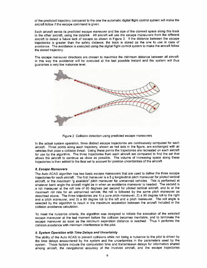
Each aircraft sends its predicted escape maneuver and the size of the claimed space along this trackto the other aircraft, using the datalink. All aircraft will use the escape maneuvers from the differentaircraft to detect a future lack of escape as shown in Figure 2. If the distance between the escapetrajectories is greater than the safety distance, the track is stored as the one to use in case ofavoidance. The avoidance is executed using the digital flight control system to make the aircraft follow
the stored trajectory.
The escape maneuver directions are chosen to maximize the minimum distance between all aircraft.In this way the avoidance will be executed at the last possible instant and the system will thusguarantee a very low nuisance level.
Figure 2 Collision detection using predicted escape maneuvers
In the actual system operation, three distinct escape trajectories are continuously computed for eachaircraft. Three points along each trajectory, shown as red dots in the figure. are exchanged with allvehicles that pose a collision threat. Using these points the trajectories are recreated on each aircraftfor use by the algorithm. The three trajectories from each aircraft are compared to find the set thatallows the aircraft to continue as close as possible. The volume of increasing space along thesetrajectories is then added to the final set to account for position uncertainties of the aircraft.
8. Escape Maneuvers
The Auto ACAS algorithm has two basic escape maneuvers that are used to define the three escapetrajectories for each aircraft. The first maneuver is a 5 g longitudinal pitch maneuver for piloted tacticalaircraft, or the maximum "g available" pitch maneuver for unmanned vehicles. This is performed atwhatever bank angle the aircraft might be in when an avoidance maneuver is needed. The second isa roll maneuver at the roll rate of 60 degrees per second for piloted tactical aircraft, and to at themaximum roll rate for an unmanned vehicle; the roll is followed by the same pitch maneuver asdescribed above. The three trajectories are 1) a pure pitch maneuver, 2) a 90 degree roll to the rightand a pitch maneuver, and 3) a 90 degree roll to the left and a pitch maneuver. The roll angle isselected by the algorithm to result in the maximum separation between the aircraft included in the
collision avoidance calculation.
To meet the nuisance criteria, the algorithm was designed to initiate the execution of the selectedescape maneuver at the last moment before the collision becomes inevitable, and to terminate theescape maneuver as soon as the minimum separation distance is reached. Thus it performs thecollision avoidance with minimum interference to the pilot.
9. System Operation with Time Delays and Uncertainty
The ability of the Auto ACAS to prevent collisions while not being a nuisance to the pilot is driven bythe time delays encountered by the system and the uncertainties in the parameters used by thesystem. These factors include the computation time and transmission delays for information sharedamong aircraft, the navigational accuracy of the involved aircraft, and the escape trajectories
6

prediction accuracy for each aircraft. It is assumed that a blended solution based on INS and GPS isavailable. An estimate of the expected computational and transmission delays were made and thesystem was designed with the ability to accommodate 300 milliseconds of delay and still provideacceptable performance. For short duration GPS losses are compensated for by allowing thenavigation uncertainty to expand as the INS position drifts. The aircraft trajectories were developed tobe accurate for the six seconds needed to enable an avoidance maneuver for most aircraft conditions.Extremely slow speed flight is currently not covered by the trajectories and will have to be the subjectof additional development. With the above delays and uncertainties it is anticipated that nuisance freecollision protection can be provided for flight with 100 to 200 feet separation for combat formations and
within the required time-to-escape window for all aspect encounters.
10. The Use of a Virtual Target from a Ground StationTesting of a collision avoidance system designed to operate during the last instance prior to a collisionpresents some interesting challenges. Flying aircraft towards a collision with only seconds to spare isan extremely high risk flight test. Several innovative concepts are being used to significantly reducethis risk.
One concept being applied is to assume that the system will always fail and to develop a test programto allows evaluation without endangering the test aircraft. This consists of distance offsets betweenthe two test aircraft. The use of a selectable exclusion zone on the autopilot inputs to prevent thealgorithm from maneuvering towards the other aircraft should some failure cause the escape roll angleto be in error to the point of trying roll the aircraft into the other test asset.
However, one of the most useful concepts is the use of a "virtual target" intruder aircraft. Initialalgorithm flight testing will be accomplished with only one real aircraft in flight. The intruder aircraft forthe test will be a computer generated virtual aircraft positioned next to and maneuvering relative to thehost vehicle. To the host aircraft and to collision avoidance system, the virtual target appears to be areal collision threat. A ground station has been developed which will contain a full six-degree offreedom simulation of the intruder aircraft with an operating Auto ACAS. The ground station includesa GPS receiver and datalink hardware. The GPS provides exact time enabling the intruder aircraft topredict its escape trajectories at the same "common" time as the test aircraft. The datalink enablesthe inclusion of real data delays and dropouts to be evaluated with real flight hardware before twoaircraft are flown together. The ground station setup is shown in Figure 3. This concept has theadded benefit of significantly reducing the setup time for data runs since the virtual aircraft can bereposition with a few keystrokes on the simulation laptop computer.
11. Conclusions and RecommendationsThe effort will show that a collision avoidance algorithm can be developed to safely maneuver amanned air vehicle automatically and not interfere with normal pilot operations. It will be required toonly function for very short time periods to prevent potentially fatal mishap. With the system operating,a pilot should be able to safely perform all maneuvers during combat training without interference fromunnecessary activation. Evaluations will show that the system would have provided protection from allof the fatal midair collisions on record.
In addition it will provide the capability for UAVs to fly closely together by removing the potential forcollisions. This will be the first necessary step in providing the capability to allow swarming ofhundreds or thousands of UAVs. This program is currently approaching the flight test phase andmuch will be learned about the suitable of the design from that testing.
Safe operation of UA Vs and manned aircraft in the same airspace can be ensured by an automaticcollision avoidance system as discussed in this paper. It will be used to prevent UAVs from hittingother aircraft flying in the vicinity regardless of failures that the UA Vs may have sustained. Theapproach described can be used for both manned fighters and UA Vs. Such a system will provideprotection that initiates at the last instant before a collision and does not interfere with normaloperations of either vehicle.
7
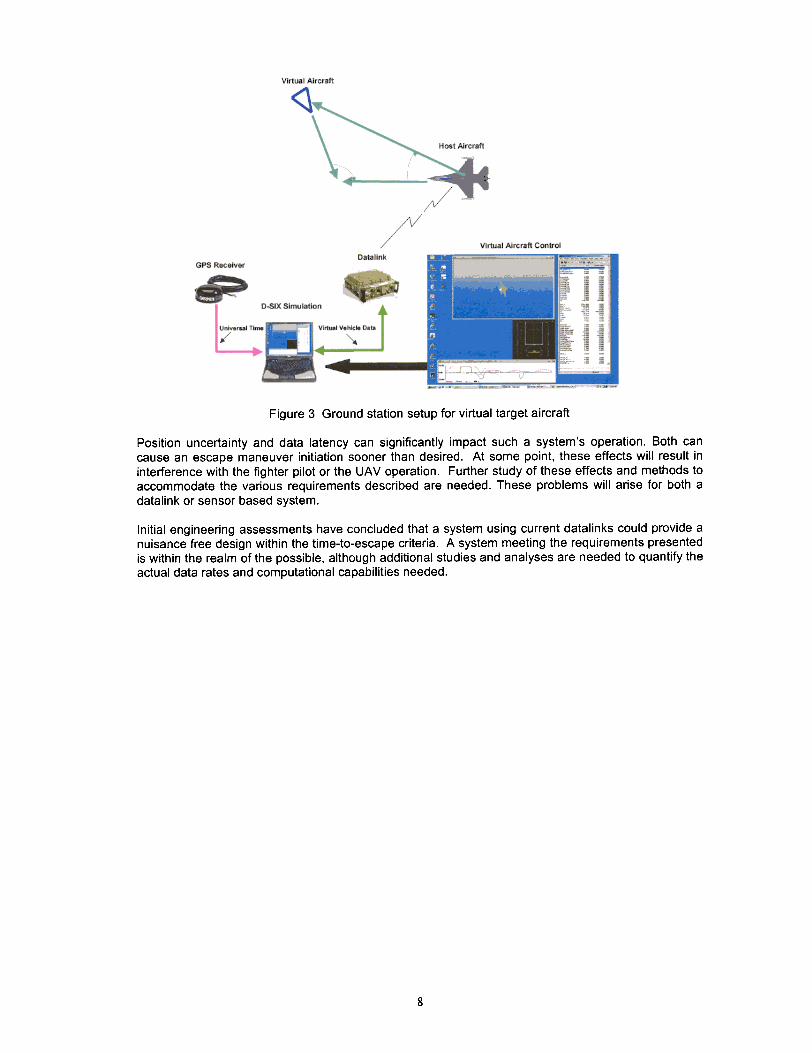
Figure 3 Ground station setup for virtual target aircraft
Position uncertainty and data latency can significantly impact such a system's operation. Both cancause an escape maneuver initiation sooner than desired. At some point, these effects will result ininterference with the fighter pilot or the UAV operation. Further study of these effects and methods toaccommodate the various requirements described are needed. These problems will arise for both adatalink or sensor based system.
Initial engineering assessments have concluded that a system using current datalinks could provide anuisance free design within the time-to-escape criteria. A system meeting the requirements presentedis within the realm of the possible, although additional studies and analyses are needed to quantify theactual data rates and computational capabilities needed.
8