Embed Size (px)
Citation preview
Air cooled and heat pumps AN series
After sales service manual
MMMiiicccrrroooccchhhiiilllllleeerrr 222
VVVEEERRRSSS...000111 Electronic
8µC2 - cod. +030220420 - rel. 2.0 - 18.10.04
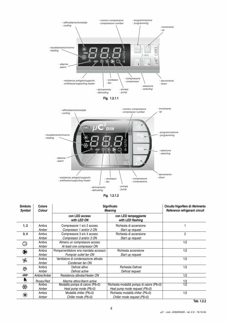
Fig. 1.2.1.1
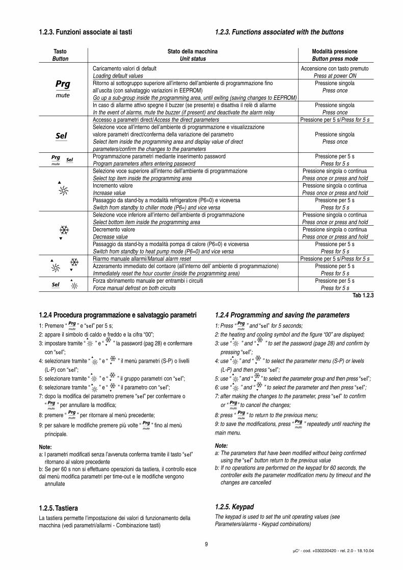
Fig. 1.2.1.2
Simbolo Colore Significato Circuito frigorifero di riferimentoSymbol Colour Meaning Reference refrigerant circuit
con LED acceso con LED lampeggiante with LED ON with LED flashing
1; 2 Ambra Compressore 1 e/o 2 acceso Richiesta di accensione 1Amber Compressor 1 and/or 2 ON Start up request
3; 4 Ambra Compressore 3 e/o 4 acceso Richiesta di accensione 2Amber Compressor 3 and/or 3 ON Start up requestAmbra Almeno un compressore acceso 1/2Amber At least one compressor ONAmbra Pompa/ventilatore aria mandata accesa/o Richiesta accensione 1/2Amber Pump/air outlet fan ON Start up requestAmbra Ventilatore di condensazione attivato 1/2Amber Condenser fan ONAmbra Defrost attivo Richiesta Defrost 1/2Amber Defrost active Defrost request
Ambra/Amber Resistenza attivata/Heater ON 1/2
Rosso/Red Allarme attivo/Alarm active 1/2Ambra Modalità pompa di calore (P6=0) Richiesta modalità pompa di calore (P6=0) 1/2Amber Heat pump mode (P6=0) Heat pump mode request (P6=0)Ambra Modalità chiller (P6=0) Richiesta modalità chiller (P6=0) 1/2Amber Chiller mode (P6=0) Chiller mode request (P6=0)
Tab. 1.2.2
1.2.3. Funzioni associate ai tasti
1.2.4 Procedura programmazione e salvataggio parametri1: Premere “ ” e “sel” per 5 s;2: appare il simbolo di caldo e freddo e la cifra “00”;3: impostare tramite “ ” e “ ” la password (pag 28) e confermare
con “sel”;4: selezionare tramite “ ” e “ ” il menù parametri (S-P) o livelli
(L-P) con “sel”;5: selezionare tramite “ ” e “ ” il gruppo parametri con “sel”;6: selezionare tramite “ ” e “ ” il parametro con “sel”;7: dopo la modifica del parametro premere “sel” per confermare o
“ ” per annullare la modifica;
8: premere “ ” per ritornare al menù precedente;
9: per salvare le modifiche premere più volte “ ” fino al menù principale.
Note:a: I parametri modificati senza l’avvenuta conferma tramite il tasto “sel”
ritornano al valore precedenteb: Se per 60 s non si effettuano operazioni da tastiera, il controllo esce dal menù modifica parametri per time-out e le modifiche vengono
annullate
1.2.5.TastieraLa tastiera permette l’impostazione dei valori di funzionamento dellamacchina (vedi parametri/allarmi - Combinazione tasti)
1.2.3. Functions associated with the buttons
1.2.4 Programming and saving the parameters1: Press “ ” and “sel” for 5 seconds;2: the heating and cooling symbol and the figure “00” are displayed;3: use “ ” and “ ” to set the password (page 28) and confirm by
pressing “sel”;4: use “ ” and “ ” to select the parameter menu (S-P) or levels
(L-P) and then press “sel”;5: use “ ” and “ ” to select the parameter group and then press “sel”;6: use “ ” and “ ” to select the parameter and then press “sel”;7: after making the changes to the parameter, press “sel” to confirm
or “ ” to cancel the changes;
8: press “ ” to return to the previous menu;9: to save the modifications, press “ ” repeatedly until reaching themain menu.
Note:a: The parameters that have been modified without being confirmed
using the “sel” button return to the previous valueb: If no operations are performed on the keypad for 60 seconds, the
controller exits the parameter modification menu by timeout and the changes are cancelled
1.2.5. KeypadThe keypad is used to set the unit operating values (seeParameters/alarms - Keypad combinations)
9µC2 - cod. +030220420 - rel. 2.0 - 18.10.04
Tasto Stato della macchina Modalità pressioneButton Unit status Button press mode
Caricamento valori di default Accensione con tasto premutoLoading default values Press at power ONRitorno al sottogruppo superiore all’interno dell’ambiente di programmazione fino Pressione singolaall’uscita (con salvataggio variazioni in EEPROM) Press onceGo up a sub-group inside the programming area, until exiting (saving changes to EEPROM)In caso di allarme attivo spegne il buzzer (se presente) e disattiva il relè di allarme Pressione singolaIn the event of alarms, mute the buzzer (if present) and deactivate the alarm relay Press onceAccesso a parametri direct/Access the direct parameters Pressione per 5 s/Press for 5 sSelezione voce all’interno dell’ambiente di programmazione e visualizzazione valore parametri direct/conferma della variazione del parametro Pressione singolaSelect item inside the programming area and display value of direct Press onceparameters/confirm the changes to the parametersProgrammazione parametri mediante inserimento password Pressione per 5 sProgram parameters afters entering password Press for 5 sSelezione voce superiore all’interno dell’ambiente di programmazione Pressione singola o continuaSelect top item inside the programming area Press once or press and holdIncremento valore Pressione singola o continuaIncrease value Press once or press and holdPassaggio da stand-by a modalità refrigeratore (P6=0) e viceversa Pressione per 5 sSwitch from standby to chiller mode (P6=) and vice versa Press for 5 sSelezione voce inferiore all’interno dell’ambiente di programmazione Pressione singola o continuaSelect bottom item inside the programming area Press once or press and holdDecremento valore Pressione singola o continuaDecrease value Press once or press and holdPassaggio da stand-by a modalità pompa di calore (P6=0) e viceversa Pressione per 5 sSwitch from standby to heat pump mode (P6=0) and vice versa Press for 5 sRiarmo manuale allarmi/Manual alarm reset Pressione per 5 s/Press for 5 sAzzeramento immediato del contaore (all’interno dell’ ambiente di programmazione) Pressione per 5 sImmediately reset the hour counter (inside the programming area) Press for 5 sForza sbrinamento manuale per entrambi i circuiti Pressione per 5 sForce manual defrost on both circuits Press for 5 s
Tab 1.2.3
Applications:
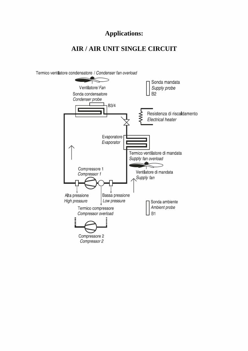
AIR / AIR UNIT SINGLE CIRCUIT
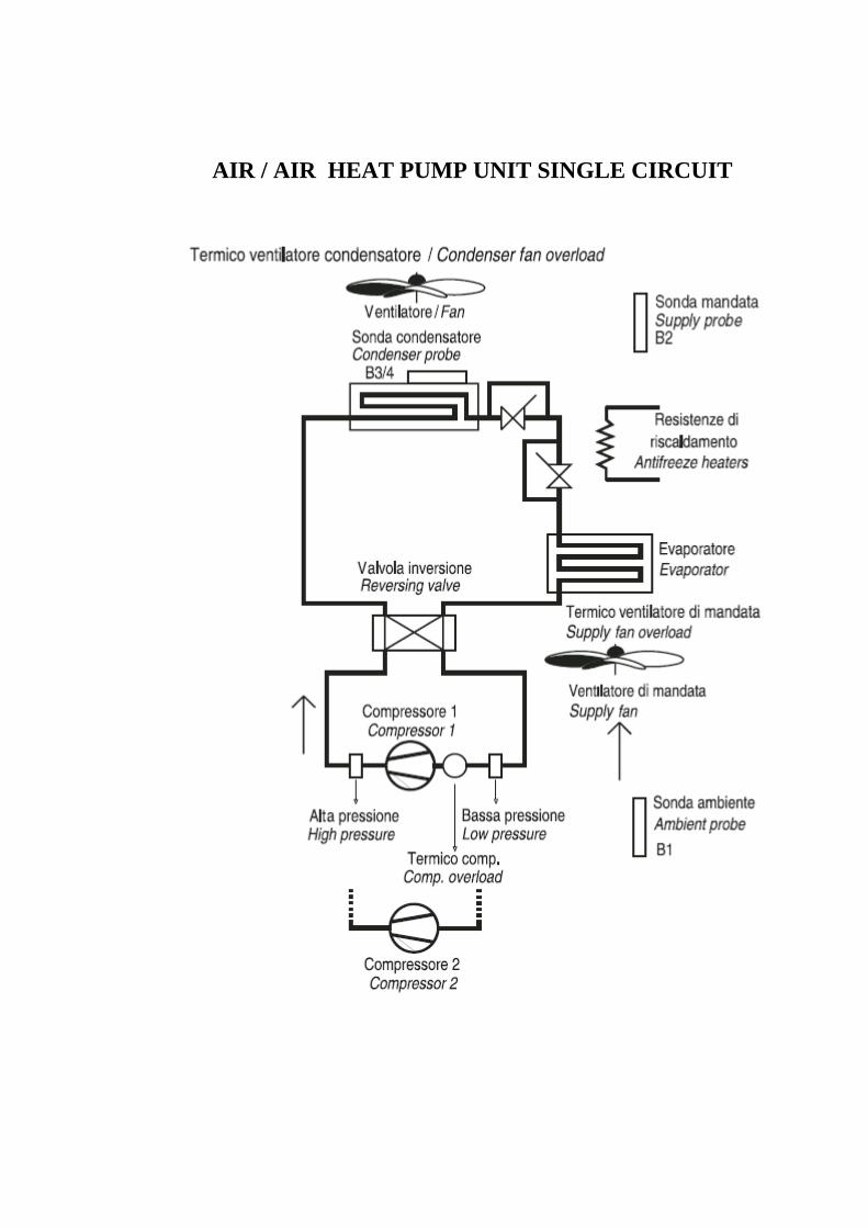
AIR / AIR HEAT PUMP UNIT SINGLE CIRCUIT

AIR / WATER UNIT SINGLE CIRCUIT
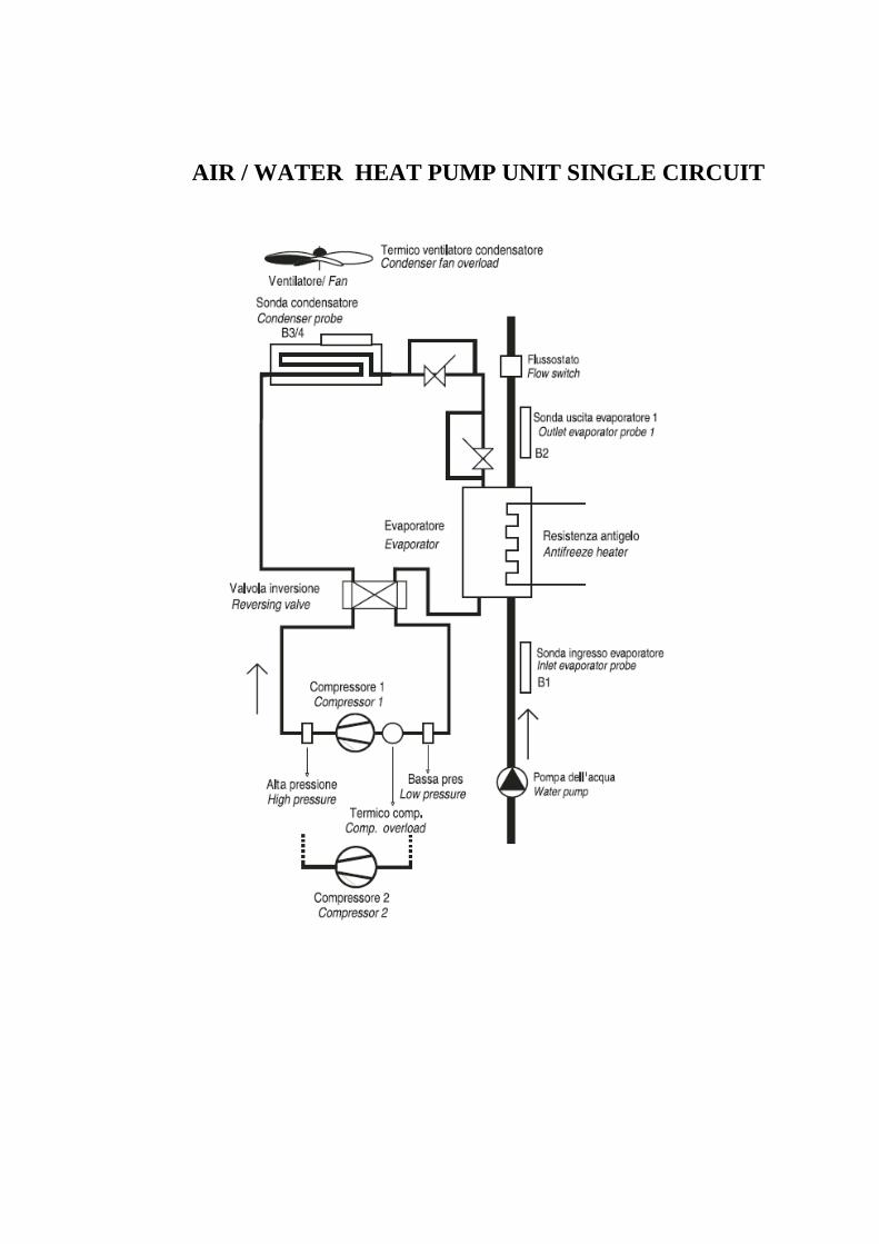
AIR / WATER HEAT PUMP UNIT SINGLE CIRCUIT
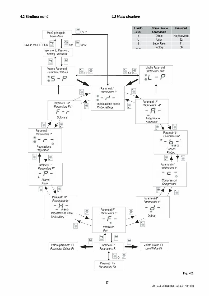
4.2 Struttura menù 4.2 Menu structure
27µC2 - cod. +030220420 - rel. 2.0 - 18.10.04
Menù principaleMain Menù
Inserimento PasswordSetting Password
Valore parametri F1Parameter Values F1
Parametri F1Parameters F1
Valore Livello F1Level Value F1
Parametri FnParameters Fn
Parametri A*Parameters A*
Parametri b*Parameters b*
Parametri /*Parameters /*
Parametri c*Parameters c*
Parametri d*Parameters d*
Parametri F*Parameters F*
Parametri H*Parameters H*
Parametri P*Parameters P*
Parametri r*Parameters r*
Parametri F-r*Parameters F-r*
Livello ParametriParameter Level
Valore ParametriParameter Values
For 5”
And For 5”Save in the EEPROM
OrOr
Or
LivelloLevel
Nome Livello PasswordLevel name
_d__U__S__F_
DirectUser
Super UserFactory
No password221166
Impostazione sondeProbe settings
RegolazioneRegulation
AllarmiAlarm
Impostazione unitàUnit setting
VentilatoriFan
CompressoriCompressor
SensoriProbes
AntighiaccioAntifreeze
Defrost
Software
Fig. 4.2

Displayindicat. Parameters AN ANH ANZ CR CRH Idro Idro H Venice Venice H HE HE H
/01 Water inlet probe B1 1 1 1 1 1 1 1 1 1 1 1/02 Water outlet probe B2 1 1 1 1 1 1 1 1 1 1 1/03 Condenser probe B3 0 1 1 0 1 0 1 0 1 0 1/04 Ambient probe B4 0 0 2 0 0 0 0 0 0 0 0/13 B1 Calibration [°C] 0 0 0 0 0 0 0 0 0 0 0/14 B2 Calibration [°C] 0 0 0 0 0 0 0 0 0 0 0/15 B3 Calibration [°C] 0 0 0 0 0 0 0 0 0 0 0/16 B4 Calibration [°C] 0 0 0 0 0 0 0 0 0 0 0/21 Digital filter 4 4 4 4 4 4 4 4 4 4 4/22 Input limitation 11 11 11 11 11 11 11 11 11 11 11/23 Unit of measure 0=°C, 1=°F 0 0 0 0 0 0 0 0 0 0 0
A01 Antifreeze set point 3 3 3 3 3 3 3 3 3 3 3A02 Differential for antifreeze [°C] 2 2 2 2 2 2 2 2 2 2 2A03 By pass time for antifreeze alarm 150 150 150 150 150 150 150 5 5 150 150A04 Set point for the activation of antifreeze heater 5 5 5 5 5 5 5 5 5 5 5A05 Diff. for antifreeze heater 2 2 2 2 2 2 2 2 2 2 2A06 Auxiliary heater probe (0= B1 probe activated) 0 0 0 0 0 0 0 0 0 0 0A07 Antifreeze alarm set point limit [°C] 2 2 2 2 2 2 2 2 2 2 2A08 Auxiliary heater set point in heating mode 5 5 5 5 5 5 5 5 5 5 5A09 Auxiliary heater differential in heating mode 2 2 2 2 2 2 2 2 2 2 2
A10 Antifreeze automatic start up (Only heater activated in standby) 3 3 3 3 3 3 3 3 3 3 3
b00 Config. Of probe to shown on the display (0 = B1) 0 0 0 0 0 0 0 0 0 0 0b01 Value read by probe B1 [°C] Vis. Vis. Vis. Vis. Vis. Vis. Vis. Vis. Vis. Vis. Vis.b02 Value read by probe B2 [°C] Vis. Vis. Vis. Vis. Vis. Vis. Vis. Vis. Vis. Vis. Vis.b03 Value read by probe B3 [°C] Vis. Vis. Vis. Vis. Vis. Vis. Vis. Vis. Vis. Vis. Vis.b04 Value read by probe B4 [°C] Vis. Vis. Vis. Vis. Vis. Vis. Vis. Vis. Vis. Vis. Vis.
µchiller Compact 2 parameters configuration
ANTIFREEZE/AUXILIARY HEATER SETTIN PARAMETERS
PROBE READING PARAMETERS
PROBE SETTING PARAMETERS

Displayindicat. Parameters AN ANH ANZ CR CRH Idro Idro H Venice Venice H HE HE H
c01 Min. compressor ON time [s] 0 0 0 0 0 0 0 0 0 0 0180 180 180 180 180 180 180 180 180 180 180
(trifase: 150)
(trifase: 150)
(trifase: 150)
(trifase: 150)
(trifase: 150)
(trifase: 150)
(trifase: 150)
(trifase: 150)
(trifase: 150)
(trifase: 150)
(trifase: 150)
c03 Delay between 2 starts of the same compressor [s] 600 600 600 600 600 600 600 600 600 600 600c04 Delay between starts of the 2 compressors 10 10 10 10 10 10 10 10 10 10 10c05 Delay between 2 shut-downs of the 2 compressors 0 0 0 0 0 0 0 0 0 0 0c06 Dealay at start up 150 150 150 150 150 150 150 30 30 150 150c07 Delay switching ON the CP after switching ON the pump 120 120 120 120 120 150 150 120 120 120 120c08 Delay switching OFF the CP after switching OFF the pump 1 1 1 1 1 1 1 1 1 1 1c09 Maximum compressor operating time in tandem 0 0 0 0 0 0 0 0 0 0 0c10 Compressor 1 timer [h] Vis. Vis. Vis. Vis. Vis. Vis. Vis. Vis. Vis. Vis. Vis.c11 Compressor 2 timer [h] Vis. Vis. Vis. Vis. Vis. Vis. Vis. Vis. Vis. Vis. Vis.c12 Compressor 3 timer [h] Vis. Vis. Vis. Vis. Vis. Vis. Vis. Vis. Vis. Vis. Vis.c13 Compressor 4 timer [h] Vis. Vis. Vis. Vis. Vis. Vis. Vis. Vis. Vis. Vis. Vis.c14 Operation timer threshold [h] 0 0 0 0 0 0 0 0 0 0 0c15 Hour counter evaporator pump Vis. Vis. Vis. Vis. Vis. Vis. Vis. Vis. Vis. Vis. Vis.c16 Hour counter condensator pump Vis. Vis. Vis. Vis. Vis. Vis. Vis. Vis. Vis. Vis. Vis.c17 Minimum time between 2 pump starts 1 1 1 1 1 1 1 1 1 1 1c18 Minimum pump On time 3 3 3 3 3 3 3 3 3 3 3
d01 Defrosting cycle [0=no; 1=yes] 0 1 1 0 1 0 1 0 1 0 1d02 Time or temperature based defrosting [1=temperature] - 1 1 - 1 - 1 - 1 - 1
d03 Start defrosting temperatur [°C] - -2.0 -2.0 - -2.0 --2.0
-3.0 su 5H
- 3-
-2
d04 End defrosting temperatur [°C] - 12 18 - 12 - 16 - 5 - 12d05 Min. time to start a defrosting cycle [s] - 10 10 - 10 - 10 - 10 - 10d06 Min. duration of a defrosting cycle [s] - 0 0 - 0 - 0 - 0 - 0d07 Max. duration of a defrosting cycle [min] - 10 - 13 Softst - 10 - 10 - 1 - 10d08 Delay between 2 defrosting cycle requestes [min] - 25 25 - 25 - 25 - 10 - 25d09 Defrosting delay between the 2 circuits [min] - 10 10 - 10 - 10 - 0 - 10d10 Defrost by external contact (0 = disabled) - 0 0 - 0 - 0 - 0 - 0
d11 Anntifreeze heaters activated while defrosting (0 = not present) - 0 0 - 0 - 0 - 0 - 0
d12 Waiting time before defrosting [min] - 1 1 - 1 - 1 - 0 - 1
COMPRESSOR SETTING PARAMETERS
c02 Min. compressor OFF time [s]
DEFROST SETTING PARAMETERS

Displayindicat. Parameters AN ANH ANZ CR CRH Idro Idro H Venice Venice H HE HE H
d13 Waiting time after defrosting [min] - 1 1 - 0 Softstart
- 1 - 1 -0
-1
d14 End defrosting with 2 circuits (0 = indipendent) - 0 0 - 0 - 0 - 0 - 0d15 Start defrosting with 2 circuits (0 = indipendent) - 0 0 - 0 - 0 - 0 - 0d16 Forced ventilation time at the end of the defrosting [s] - 0 0 - 0 - 0 - 0 - 0d17 Defrost with compressors OFF - 0 0 - 0 - 0 - 0 - 0
F01 Fan output (1 = fan present) 1 1 1 1 1 1 1 0 0 1 1F02 Fan operating mode (1 = depending on the compressor) 1 1 1 1 1 1 1 - - 1 1F03 Min. voltage threshold for triac 25 0 0 25 0 25 0 - - 25 0F04 Max. voltage threshold for triac 90 100 100 90 100 90 100 - - 90 100F05 Temp.value for min. speed cooling [°C] - 35 35 - 35 - 35 - - - 35F06 Differential value for max. speed cooling - 10 10 - 10 - 10 - - - 10F07 Fan shut-down differential in cooling mode - 15 15 - 15 - 15 - - - 15F08 Temperature value for max. speed in heating mode - 35 35 - 35 - 35 - - - 35F09 Differential value for max. speed heating - 5 5 - 5 - 5 - - - 5F10 Temp. To turn OFF the fan in heating - 5 5 - 5 - 5 - - - 5F11 Fan starting time [s] - 0 0 - 0 - 0 - - - 0F12 Triac impulse duration [s] 0 0 0 0 - - - 0F13 Fan management in defrost mede (0 = disabled) - 0 0 - 0 - 0 - - - 0F14 Fan ON time when starting in high condensing temp. [s] 0 0 0 0 - - - 0
H01 Unit model [2=air-water / chiller; 3=air-water / heat pump] 2 3 3 2 3 2 3 2 3 2 3H02 Numbers of condensers [0 = 1 condenser] 0 0 0 0 0 0 0 0 0 0 0H03 Numbers of evaporators [0 = 1 evaporator] 0 0 0 0 0 0 0 0 0 0 0H04 Numbers of compressors per circuit [0 = single circuit] 0 0 0 0 0 0 0 0 0 0 0H05 Pump mode [1 = always ON] 1 1 1 1 1 1 1 1 1 1 1H06 Cooling/Heating digital input (0=absent, 1=present) 0 1 1 0 1 0 0 0 1 0 1H07 ON/OFF digital input (0=absent, 1=present) 1 1 1 1 1 1 1 1 1 1 1H08 uC2 network configuration (0 = only uC2) 0 0 0 0 0 0 0 0 0 0 0H09 Lock keypad (1 = enabled) 1 1 1 1 1 1 1 1 1 1 1H10 Serial address 1 1 1 1 1 1 1 1 1 1 1
H11 Output modes(0 = standard, 5 = output C1/2 – No4 used as fan) 5 0 0 5 0 5 0 0 0 5 0
H12 Inversion valve management (ON in Heating mode) 1 1 1 1 1 1 1 1 1 1 1H21 Second pump function (0 = disabled) 0 0 0 0 0 0 0 0 0 0 0
UNIT SETTING PARAMETERS
FAN SETTING PARAMETERS

Displayindicat. Parameters AN ANH ANZ CR CRH Idro Idro H Venice Venice H HE HE H
H22 Disabled load default values (0 = disabled) 0 0 0 0 0 0 0 0 0 0 0H23 Enable Modbus protocol 0 0 0 0 0 0 0 0 0 0 0
H96 Software version Driver 2 Vis. Vis. Vis. Vis. Vis. Vis. Vis. Vis. Vis. Vis. Vis.H97 Software version Driver 1 Vis. Vis. Vis. Vis. Vis. Vis. Vis. Vis. Vis. Vis. Vis.H98 Expansion software version Vis. Vis. Vis. Vis. Vis. Vis. Vis. Vis. Vis. Vis. Vis.H99 Software version ( 1.7) Vis. Vis. Vis. Vis. Vis. Vis. Vis. Vis. Vis. Vis. Vis.
P01 Flow switch alarm delay when starting the pump [s] 20 20 20 20 20 20 20 20 20 20 20P02 Flow switch alarm delay during steady operation [s] 5 5 5 5 5 5 5 5 5 5 5P03 Low pressure alarm delay at start up [s] 180 180 180 180 180 199 199 180 180 180 180P05 Alarm reset (0 = HP, LP and antifreeze with manual reset) 0 0 0 0 0 0 0 0 0 0 0P06 Cooling/Heating logic (1= Sun Heat Pump/ Snow Chiller) 1 1 1 1 1 1 1 1 1 1 1P07 Low pressure alarm from trasducer (0=Disabled) 0 0 0 0 0 0 0 0 0 0 0
P08 Digital input ID1 selection (4=general thermal overload, 10=cooling/heating, O= none 4 10 10 4 10 0 10 4 10 4 10
P09 Digital input ID2 selection (1 = Flow switch manual reset) 1 (PD) 1 (PD) 1 (PD) 1 (PD) 1 (PD) 1 (PD) 1 (PD) 1 1 1 1P13 Configuration of B4 se /04 = 1 0 0 0 0 0 0 0 0 0 0 0
P15 Low pressure alarm configuration (1 = alarm detected also with compressor OFF) 1 1 1 1 1 1 1 1 1 1 1
P16 High temperature alarm set [°C] 90 90 90 60 60 90 90 60 60 90 90P17 High temperature alarm delay at start-up [min.] 30 30 30 180 180 30 30 15 15 30 30P19 System low temperature alarm set point [°C] 4 4 4 5 5 4 4 4 4 4 4P20 Enable system start-up protection (0 = disabled) 0 0 0 0 0 0 0 0 0 0 0P21 Alarm relay management (0=normally open) 0 0 0 0 0 0 0 0 0 0 0
r01 Cooling set point [°C] 11 11 11 11 11 10 10 11 11 22 22r02 Cooling differential [°C] 2 2 2 2 2 2 2 2 2 2 2r03 Heating set point [°C] 40 41 41 40 41 40 46 40 41 40 31r04 Heating differential [°C] 3 2 2 3 2 3 2 3 2 3 2r05 Compressor rotation (0 = disabled) 0 0 0 0 0 0 0 0 0 0 0r06 Type of compressor control (0 = proportional on inlet) 0 0 0 0 0 0 0 0 0 0 0r07 Dead zone differential [°C] 2 2 2 2 2 2 2 2 2 2 2r08 Activation delay at lower limit of r07 [s] 120 120 120 120 120 120 120 120 120 120 120r09 Activation delay at upper limit of r07 [s] 100 100 100 100 100 100 100 100 100 100 100r10 Deactivation delay at lower limit of r12 [s] 120 120 120 120 120 120 120 120 120 120 120r11 Deactivation delay at upper limit of r12 [s] 100 100 100 100 100 100 100 100 100 100 100
CONTROL SETTING PARAMETERS
ALARM SETTING PARAMETERS
Displayindicat. Parameters AN ANH ANZ CR CRH Idro Idro H Venice Venice H HE HE H
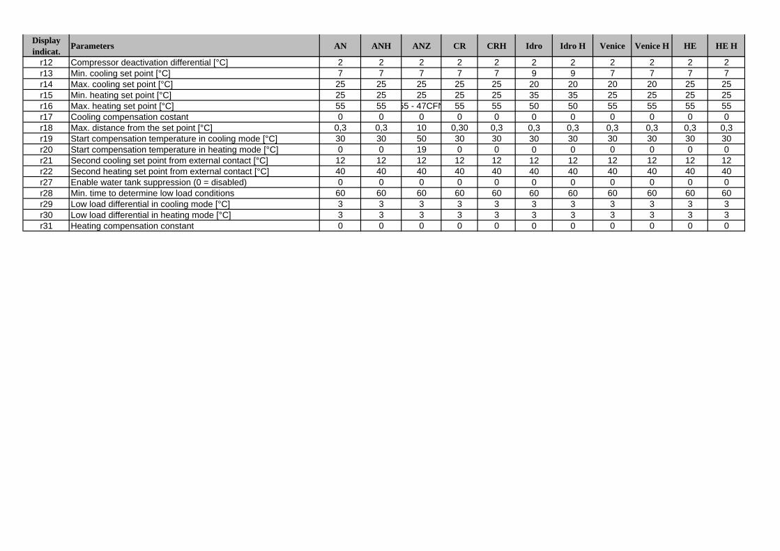
r12 Compressor deactivation differential [°C] 2 2 2 2 2 2 2 2 2 2 2r13 Min. cooling set point [°C] 7 7 7 7 7 9 9 7 7 7 7r14 Max. cooling set point [°C] 25 25 25 25 25 20 20 20 20 25 25r15 Min. heating set point [°C] 25 25 25 25 25 35 35 25 25 25 25r16 Max. heating set point [°C] 55 55 55 - 47CFN 55 55 50 50 55 55 55 55r17 Cooling compensation costant 0 0 0 0 0 0 0 0 0 0 0r18 Max. distance from the set point [°C] 0,3 0,3 10 0,30 0,3 0,3 0,3 0,3 0,3 0,3 0,3r19 Start compensation temperature in cooling mode [°C] 30 30 50 30 30 30 30 30 30 30 30r20 Start compensation temperature in heating mode [°C] 0 0 19 0 0 0 0 0 0 0 0r21 Second cooling set point from external contact [°C] 12 12 12 12 12 12 12 12 12 12 12r22 Second heating set point from external contact [°C] 40 40 40 40 40 40 40 40 40 40 40r27 Enable water tank suppression (0 = disabled) 0 0 0 0 0 0 0 0 0 0 0r28 Min. time to determine low load conditions 60 60 60 60 60 60 60 60 60 60 60r29 Low load differential in cooling mode [°C] 3 3 3 3 3 3 3 3 3 3 3r30 Low load differential in heating mode [°C] 3 3 3 3 3 3 3 3 3 3 3r31 Heating compensation constant 0 0 0 0 0 0 0 0 0 0 0

Displayindicat. Parameters AN ANH ANZ CR CRH Idro Idro H Venice Venice H HE HE H
descrizione Reset Pump Fan Heater Alarm
HP1 High pressure manual - on (60 - onLP1 Low pressure manual - off - onTP Thermal protection automatic - off - onFL Flow switch manual off off - on
E1, E2, E3,E4 Probe alarm automatic off off - on
EPr Eeprom error during operation automatic - - - onEPb Eeprom error at the start-up automatic off off off offdF1 Defrosting error automatic - - - -d1 Defrost ON - - - - -A1 Antifreeze alarm manual - off - on
ELS Low supply voltage automatic - - - -EHS High supply voltage automatic off off off -
d Directu Users Superuser
-off
TABEL OF ALARMS
----
--
-
11
Compressor
offoffoff
no password22
Password
-off--
off-
off
off
Reverse valve
--
-
off
4.3 Tabelle parametriDi seguito sono riportate le tabelle dei parametri suddivise per tipo difamiglia (es. compressore, sonde, ventilatori ecc.).
• Legenda tabella parametriLivello (default)U= userS= super userF= factory
Visibilità:La visibilità di alcuni gruppi è condizionata dal tipo di controllo e dalvalore dei parametri.
D= sbrinamento (se D01=1)F= ventilatore (se F01=1)N= sonda NTC (se /04-/08=2)P= pressione (se /04-/08=3)V= driver (se H08 =1-3)X= espansione (se H08=2-3)- = sempre presente
Variabile Supervisore:R/W = parametro di lettura/scrittura a supervisoreR = parametro di sola lettura a supervisore
4.3.1 Parametri impostazione sonde: (/*)
4.3 Parameter tablesThe following tables show of the parameters divided by type/family (e.g. compressor, probes, fans etc.).
• Key to the parameter tablesLevel (default)U= userS= super userF= factory
Visibility:The visibility of some groups depends on the type of controller and thevalue of the parameters.
D= defrost (if D01=1)F= fan (if F01=1)N= NTC probe (if /04-/08=2)P= pressure (if /04-/08=3)V= driver (if H08 =1-3)X= expansion (if H08=2-3)- = always present
Supervisor variables:R/W= supervisor read/write parameterR= supervisor read-only parameter
4.3.1 Probe setting parameters: (/*)
28µC2 - cod. +030220420 - rel. 2.0 - 18.10.04
Parametri impostazione sonde/Probe setting parametersIndicaz. Parametro e descrizione Livello Min. Max. U.M. Variazione Default Visibilità Variabile TipoDisplay Parameter and description Default Min. Max. U.O.M. Variation Default Visibility Superv. Variabile.Display Default Supervis. VariabileIndication Level Variable Type
/01 Tipo sonda B1/Probe type B1 F 0 1 Flag 1 1 - 1 (R/W) Digital0= Non presente/not present1= Presente/present
/02 Tipo sonda B2/Probe type B2 F 0 1 Flag 1 0 - 2 (R/W) Digital0= Non presente/not present1= Presente/present
/03 Tipo sonda B3/Probe type B3 F 0 2 Flag 1 0 - 14 (R/W) Integear0= Non presente/not present1= NTC Sonda Cond./NTC Cond. Probe 2= NTC Sonda ext. /NTC Out. Probe
/04 Tipo sonda B4/Probe Type B4 F 0 3 Flag 1 0 - 15 (R/W) Integear0= Non presente/not present1= ON/OFF (D.I)2= NTC Sonda ext. /Out. probe3= Sonda raziometrica cond. 5 Vdc
Ratiometric cond. Probe, 5 Vdc/05 Tipo sonda B5/Probe Type B5 F 0 1 Flag 1 0 X 3 (R/W) Digital
0= Non presente/not present1= Presente/present
/06 Tipo sonda B6/Probe Type B6 F 0 1 Flag 1 0 X 4 (R/W) Digital0= Non presente/not present1= Presente/present
/07 Tipo sonda B7/Probe Type B7 F 0 2 Flag 1 0 X 16 (R/W) Integear0= Non presente/not present1= NTC Sonda Cond./NTC Cond. Probe 2= NTC Sonda ext./NTC Out. Probe
/08 Tipo sonda B8 (espansione) F 0 3 Flag 1 0 X 17 (R/W) IntegearType of probe B8 (expansion)0= Non presente/not present1= ON/OFF2= NTC Sonda ext/Out. probe3= Sonda Raziometrica Cond. 5 Vdc
Ratiometric cond. probe, 5 Vdc/09 Valore minimo ingresso in tensione F 0 /10 0.01 Vdc 1 50 P 18 (R/W) Integear
Min. value voltage input/10 Valore massimo ingresso in tensione F /09 500 0.01 Vdc 1 450 P 19 (R/W) Integear
Max. value voltage inputcontinua.../continues...
4.3.2 Parametri impostazione antigelo-resistenze appoggio (A*) 4.3.2 Antifreeze/auxiliary heater setting parameters (A*)
29µC2 - cod. +030220420 - rel. 2.0 - 18.10.04
Parametri impostazione sonde/Probe setting parametersIndicaz. Parametro e descrizione Livello Min. Max. U.M. Variazione Default Visibilità Variabile TipoDisplay Parameter and description Default Min. Max. U.O.M. Variation Default Visibility Superv. Variabile.Display Default Supervis. VariabileIndication Level Variable Type
/11 Valore minimo pressione/Pressure min. value F 0 /12 bar 1 0 P 1 (R/W) Analog/12 Valore massimo pressione/Pressure max. value F /11 99.9 bar 1 34.5 P 2 (R/W) Analog/13 Calibrazione sonda B1/Probe B1 calibration F -12.0 12.0 °C/°F 0.1 0.0 - 3 (R/W) Analog/14 Calibrazione sonda B2/Probe B2 calibration F -12.0 12.0 °C/°F 0.1 0.0 - 4 (R/W) Analog/15 Calibrazione sonda B3/Probe B3 calibration F -12.0 12.0 °C/°F 0.1 0.0 - 5 (R/W) Analog/16 Calibrazione sonda B4/Probe B4 calibration F -12.0 12.0 °C/bar/°F 0.1 0.0 - 6 (R/W) Analog/17 Calibrazione sonda B5/Probe B5 calibration F -12.0 12.0 °C/°F 0.1 0.0 X 7 (R/W) Analog/18 Calibrazione sonda B6/Probe B6 calibration F -12.0 12.0 °C/°F 0.1 0.0 X 8 (R/W) Analog/19 Calibrazione sonda B7/Probe B7 calibration F -12.0 12.0 °C/°F 0.1 0.0 X 9 (R/W) Analog/20 Calibrazione sonda B8/Probe B8 calibration F -12.0 12.0 °C/bar/°F 0.1 0.0 X 10 (R/W) Analog/21 Filtro digitale/Digital filter U 1 15 - 1 4 - 20 (R/W) Integear/22 Limitazione ingresso/Input limitation U 1 15 - 1 8 - 21 (R/W) Integear/23 Unità di misura/Unit of measure U 0 1 Flag 1 0 - 5 (R/W) Digital
0= °C1= °F
Tab. 4.3.1
Parametri impostazione antigelo-resistenze di appoggio /Antifreeze/auxiliary heater setting parametersIndicaz. Parametro e descrizione Livello Min. Max. U.M. Variazione Default Visibilità Variabile TipoDisplay Parameter and description Default Min. Max. U.O.M. Variation Default Visibility Superv. Variabile.Display Default Supervis. VariabileIndication Level Variable Type
A01 Set allarme antigelo/bassa temp. amb. (Aria/Aria) U A07 A04 °C/°F 0.1 3.0 - 11 (R/W) AnalogAntifreeze/low ambient temp. (air/air) alarmset point
A02 Differenziale allarme antigelo/bassa U 0.3 °C 0.1 5.0 - 12 (R/W) Analogtemperatura ambiente (Aria/Aria) 0.3 122.0 °FDifferential for antifreeze/low ambienttemperature alarm
A03 Tempo bypass allarme antigelo/bassa temp. U 0 150 S 1 0 - 22 (R/W) Integearambiente all'accensione della macchina in InvernoBypass time for antifreeze alarm/low ambient temp.when turning on the unit in heating mode
A04 Set resistenza antigelo/appoggio U A01 r16 °C/°F 0.1 5.0 - 13 (R/W) AnalogSet point for the activation of antifreezeheater/auxiliary heater
A05 Differenziale resistenza antigelo/appoggio U 0.3 50.0 °C/°F 0.1 1.0 - 14 (R/W) AnalogDiff. for antifreeze heater/auxiliary heater
A06 Sonda resistenze di appoggio F 0 1 Flag 1 0 - 6 (R/W) DigitalAuxiliary heater probe0= Sonda di controllo vedi (Tab. 5.1)
Control probe see (Tab. 5.1)1= Sonda antigelo vedi (Tab 5.1)
Antifreeze probe see (Tab. 5.1)A07 Limite set allarme antigelo F -40.0 °C 0.1 -40.0 - 15 (R/W) Analog
Antifreeze alarm set point limit -40.0 176.0 °FA08 Set resistenza di appoggio in riscaldamento U A01 r15 °C 0.1 25.0 - 16 (R/W) Analog
Auxiliary heater set point in heating mode °FA09 Diff. Resistenza di appoggio in riscaldamento U 0.3 50.0 °C/°F 0.1 3.0 - 17 (R/W) Analog
Auxiliary heater differential in heating modeA10 Accensione automatica antigelo U 0 3 Flag 1 0 - 23 (R/W) Integear
Antifreeze automatic start up0= Funzione disabilitata/disabled function1= Resistenze e pompa accese
contemporaneamente su A4/A8Heaters and pump on at the same time on A4/A8
2= Resistenze e pompa accese indipendentemente su A4/A8Heaters and pump on indipendently on A4/A8
3= Resistenze accese su A4/A8Heaters ON on A4/A8
Tab. 4.3.2

4.3.3 Parametri lettura sonde (B*) 4.3.3 Probe reading parameters (B*)
30µC2 - cod. +030220420 - rel. 2.0 - 18.10.04
Parametri lettura sonde/Probe reading parametersIndicaz. Parametro e descrizione Livello Min. Max. U.M. Variazione Default Visibilità Variabile TipoDisplay Parameter and description Default Min. Max. U.O.M. Variation Default Visibility Superv. Variabile.Display Default Supervis. VariabileIndication Level Variable Type
b00 Selezione sonda da visualizzare sul display U 0 10 Flag 1 0 - 24 (R/W) IntegearConfig. of probe to be shown on the display0 = sonda/probe B11 = sonda/probe B22 = sonda/probe B33 = sonda/probe B44 = sonda/probe B55 = sonda/probe B66 = sonda/probe B77 = sonda/probe B88 = set point senza compensazione
set point without compensation9 = set point (dinamico) con eventuale
compensazionedynamic set point with possiblecompensation
10 = stato ingresso digitale ON/OFF remotoremote ON/OFF digital input status
b01 Valore letto dalla sonda B1 D - - °C /°F - - - 70 (R) AnalogValue read by probe B1
b02 Valore letto dalla sonda B2 D - - °C /°F - - - 71 (R) AnalogValue read by probe B2
b03 Valore letto dalla sonda B3 D - - °C /°F - - - 72 (R) AnalogValue read by probe B3
b04 Valore letto dalla sonda B4 D - - °C /°F/ - - - 73 (R) AnalogValue read by probe B4 bar
b05 Valore letto dalla sonda B5 D - - °C /°F - - X 74 (R) AnalogValue read by probe B5
b06 Valore letto dalla sonda B6 D - - °C /°F - - X 75 (R) AnalogValue read by probe B6
b07 Valore letto dalla sonda B7 D - - °C /°F - - X 76 (R) AnalogValue read by probe B7
b08 Valore letto dalla sonda B8 D - - °C /°F - - X 77 (R) AnalogValue read by probe B8 bar
b09 Temperatura evaporatore Driver 1 D - - °C /°F - - V 78 (R) AnalogDriver 1 evaporator temperature
b10 Pressione evaporatore Driver 1 D - - bar - - V 79 (R) AnalogDriver 1 evaporator pressure
b11 Surriscaldamento Driver 1 D - - °C /°F - - V 80 (R) AnalogDriver 1 superheating
b12 Temperatura saturazione Driver 1 D - - °C /°F - - V 81 (R) AnalogDriver 1 saturation temperature
b13 Posizione valvola Driver 1 D 0 100.0 % - - V 82 (R) AnalogDriver 1 valve position
b14 Temperatura evaporatore Driver 2 D - - °C /°F - - XV 83 (R) AnalogDriver 2 evaporator temperature
b15 Pressione evaporatore Driver 2 D - - bar - - XV 84 (R) AnalogDriver 2 evaporator pressure
b16 Surriscaldamento Driver 2 D - - °C /°F - - XV 85 (R) AnalogDriver 2 superheating
b17 Temperatura saturazione Driver 2 D - - °C /°F - - XV 86 (R) AnalogDriver 2 saturation temperature
b18 Posizione valvola Driver 2 D 0 100.0 % - - XV 87 (R) AnalogDriver 2 valve position
b19 Sonda temp. uscita scambiatore esterno c1 D - - °C /°F - - V 88 (R) AnalogTemp. probe at the outlet of the external coil c1
b20 Sonda temp. uscita scambiatore esterno c2 D - - °C /°F - - XV 89 (R) AnalogTemp. probe at the outlet of the external coil c12
Tab. 4.3.3

4.3.4 Parametri impostazione compressori (c*) 4.3.4 Compressor setting parameters (c*)
31µC2 - cod. +030220420 - rel. 2.0 - 18.10.04
Parametri lettura sonde/Compressor setting parametersIndicaz. Parametro e descrizione Livello Min. Max. U.M. Variazione Default Visibilità Variabile TipoDisplay Parameter and description Default Min. Max. U.O.M. Variation Default Visibility Superv. Variabile.Display Default Supervis. VariabileIndication Level Variable Type
c01 Tempo minimo di accensione compressore U 0 999 s 1 60 - 25 (R/W) IntegearMin. compressor ON time
c02 Tempo minimo di spegnimento compressore U 0 999 s 1 60 - 26 (R/W) IntegearMin. OFF time compressor
c03 Ritardo tra 2 accensioni dello stesso U 0 999 s 1 360 - 27 (R/W) IntegearcompressoreDelay between 2 starts of the samecompressor
c04 Ritardo accensione tra i 2 compressori U 0 999 s 1 10 - 28 (R/W) IntegearDelay between starts of the 2 compressors
c05 Ritardo spegnimento tra i 2 compressori U 0 999 s 1 0 - 29 (R/W) IntegearDelay between 2 shut-downs of the 2compressors
c06 Ritardo all'accensione/Delay at start-up U 0 999 s 1 0 - 30 (R/W) Integearc07 Ritardo accensione compressore dalla U 0 150 s 1 20 - 31 (R/W) Integear
partenza pompa/ventilatore mandataDelay in switching on the compressor afterswitching on the pump/inlet fan (air/air)
c08 Ritardo spegnimento pompa/ventilatore U 0 150 min 1 1 - 32 (R/W) Integearmandata dallo spegnimento compressoreDelay in switching OFF the compressor afterswitching OFF the pump/inlet fan (air/air)
c09 Tempo massimo funzionamento compressore U 0 60 min 1 0 - 33 (R/W) Integearin tandem/Maximum compressor operatingtime in tandem
c10 Contaore compr. 1/Compressor 1 timer D 0 800.0 100 hours 0.1 0 - 90 (R) Analogc11 Contaore compr. 2/Compressor 2 timer D 0 800.0 100 hours 0.1 0 - 91 (R) Analogc12 Contaore compr. 3/Compressor 3 timer D 0 800.0 100 hours 0.1 0 - 92 (R) Analogc13 Contaore compr. 4/Compressor 4 timer D 0 800.0 100 hours 0.1 0 - 93 (R) Analogc14 Soglia contaore di funzionamento U 0 100 100 hours 1 0 - 34 (R/W) Int.
Operation timer thresholdc15 Contaore pompa evaporatore/ventilatore 1 D 0 800.0 100 hours 0.1 0 - 94 (R) Analog
Hour counter evaporator pump/fan 1c16 Contaore pompa condensatore D 0 800.0 100 hours 0.1 0 - 95 (R) Analog
backup/ventilatore 2Hour counter condenser backup pump/fan 2
c17 Tempo minimo tra 2 accensioni pompa U 0 150 min 1 30 - 35 (R/W) IntegearMinimum time between 2 pump starts
c18 Tempo minimo accensione pompa U 0 15 min 1 3 - 36 (R/W) IntegearMinimum pump ON time
Tab. 4.3.4
4.3.5 Parametri impostazione sbrinamento (d*) 4.3.5 Defrost setting parameters (d*)
32µC2 - cod. +030220420 - rel. 2.0 - 18.10.04
Parametri lettura sonde/Compressor setting parametersIndicaz. Parametro e descrizione Livello Min. Max. U.M. Variazione Default Visibilità Variabile TipoDisplay Parameter and description Default Min. Max. U.O.M. Variation Default Visibility Superv. Variabile.Display Default Supervis. VariabileIndication Level Variable Type
d01 Esecuzione sbrinamento/Antigelo cond. U 0 1 Flag 1 0 - 7 (R/W) DigitalDefrosting cycle/Condenser antifreeze0= no1= sì con sbrinamento unificato
yes with shared defrostingd02 Sbrinamento a tempo o a temp. - press. U 0 1 Flag 1 0 D 8 (R/W) Digital
Time or temp.- press. based defrosting0= tempo/time1= temp. - press/temp. - press
d03 Temperatura inizio sbrinamento U -40.0 d04 °C/°F 0.1 -5.0 DN 19 (R/W) AnalogStart defrosting temperatureSet allarme antigelo condensazioneCondenser antifreeze alarm set pointPressione inizio sbrinamento /11 d04 bar 0.1 3.5 DP 18 (R/W) AnalogStart defrosting pressure
d04 Temperatura fine sbrinamento U d03 °C 0.1 20.0 DN 21 (R/W) AnalogEnd defrosting temperature d03 176.0 °F 0.1Pressione fine sbrinamento/End defrosting pressure d03 /12 bar 0.1 14.0 DP 20 (R/W) Analog
d05 Tempo minimo per inizio sbrinamento U 10 150 s 1 10 D 37 (R/W) IntegearMin. time to start a defrosting cycle
d06 Durata minima sbrinamento U 0 150 s 1 0 D 38 (R/W) IntegearMin. duration of a defrosting cycle
d07 Durata massima sbrinamento U 1 150 min 1 5 D 39 (R/W) IntegearMax. duration of a defrosting cycle
d08 Ritardo tra due richieste sbrinamento nello U 10 150 min 1 30 D 40 (R/W) Integearstesso circuito/Delay between 2 defrostingcycle requests within the same circuit
d09 Ritardo sbrinamento tra i 2 circuiti U 0 150 min 1 10 D 41 (R/W) IntegearDefrosting delay between the 2 circuits
d10 Sbrinamento da contatto esterno F 0 3 Flag 1 0 D 42 (R/W) IntegearDefrost by external contact0= Funzione disabilitata/disables function1= Inizio da contatto esterno/external contact start2= Fine da contatto esterno/external contact end3= Inizio e fine da contatto esterno
external contact start and endd11 Resistenze antigelo in sbrinamento U 0 1 Flag 1 0 D 9 (R/W) Digital
Antifreeze heaters activated while defrosting0= Non presenti/Not present1= Presenti/Present
d12 Tempo di attesa prima dello sbrinamento F 0 3 min 1 0 D 43 (R/W) IntegearWaiting time before defrosting
d13 Tempo di attesa dopo lo sbrinamento F 0 3 min 1 0 D 44 (R/W) IntegearWaiting time after defrosting
d14 Fine sbrinamento con 2 circuiti frigoriferi F 0 2 Flag 1 0 D 45 (R/W) IntegearEnd defrosting with 2 refrigerating circuits0= Indipendenti/Indipendent1= Se entrambi in condizione di fine sbrinam.
If both at end defrost2= Se almeno uno in condizione di fine sbrinam.
If at least one at end defrostd15 Inizio sbrinamento con 2 circuiti F 0 2 Flag 1 0 D 46 (R/W) Integear
Start defrost with 2 circuits0= Indipendenti/Indipendent1= Se entrambi in condizione di inizio sbrinam.
If both at start defrost2= Se almeno uno in condizione di inizio sbrinam.
If at least one at start defrostd16 Tempo di ventilazione forzata in fine sbrinam. F 0 360 s 1 0 D 47 (R/W) Integear
Forced ventilation time at the end of the defrostingd17 Sbrinamento a compressori spenti F 0 80.0 °C/°F 0.1 0 D 22 (R/W) Analog
Defrost with compressors OFFTab. 4.3.5

4.3.6 Parametri impostazione ventilatori (F*) 4.3.6 Fan setting parameters (F*)
33µC2 - cod. +030220420 - rel. 2.0 - 18.10.04
Parametri impostazione ventilatori/Fan setting parametersIndicaz. Parametro e descrizione Livello Min. Max. U.M. Variazione Default Visibilità Variabile TipoDisplay Parameter and description Default Min. Max. U.O.M. Variation Default Visibility Superv. Variabile.Display Default Supervis. VariabileIndication Level Variable Type
F01 Uscita ventilatori/Fan output F 0 1 Flag 1 0 - 10 (R/W) Digital0=assente/absent1=presente/present
F02 Modalità funz. ventilatori U 0 3 Flag 1 0 F 48 (R/W) IntegearFan operating mode0= sempre acceso/0= always ON1= legate al compr. (funzionamento in parallelo)
depending ON the compressor(in parallel operation mode)
2= legate al compr. con regolazione ON/OFFdepending ON the compressors inON/OFF control
3= legate al compr. con regolaz. in velocitàdepending ON the compressors inspeed control mode
F03 Soglia tensione minima per Triac F 0 F04 step 1 35 F 49 (R/W) IntegearMin. voltage threshold for Triac
F04 Soglia tensione massima per Triac F F03 100 step 1 75 F 50 (R/W) IntegearMax. voltage threshold for Triac
F05 Temp. min. velocità in modalità Estate U -40.0 °C 0.1 35.0 FN 24 (R/W) AnalogTemp. value for min. speed Cooling -40.0 176.0 °F 0.1Pressione min. velocità in modalità Estate /11 /12 bar 0.1 13.0 FP 23 (R/W) AnalogPressure value for min. speed Cooling
F06 Differenziale massima velocità in U 0 50.0 °C/°F 0.1 10.0 FN 26 R/W) Analogmodalità EstateDifferential value for max. speed CoolingPressione max. velocità in modalità Estate 0 300 bar 0.1 3.0 FP 25 (R/W) AnalogPressure value for max. speed Cooling
F07 Diff. spegnimento ventilatori in U 0 50.0 °C/°F 0.1 15.0 FN 28 (R/W) Analogmodalità EstateFan shut-down differential in Cooling modePressione spegnimento ventilatori in 0 F5 bar 0.1 5.0 FP 27 (R/W) Analogmodalità EstateFan shut-down pressure in Cooling mode
F08 Temp. min. velocità in modalità Inverno U -40.0 °C 0.1 35.0 FN 30 (R/W) AnalogTemperature value for max speed in -40.0 176.0 °F 0.1Heating modePressione min. velocità in modalità Inverno /11 /12 bar 0.1 13.0 FP 29 (R/W) AnalogPressure value for max speed in Heating
F09 Diff. temp. max. velocità in modalità Inverno U 0 50.0 °C/°F 0.1 5.0 FN 32 (R/W) AnalogTemperature value for max. speed inHeating modePressione max. velocità in modalità Inverno 0 F08 bar 0.1 4.0 FP 31 (R/W) AnalogPressure value for max speed in Heating
F10 Diff. temp. spegnimento ventilatori in U 0 F08 °C/°F 0.1 5.0 FN 34 (R/W) Analogmodalità InvernoTemp. to turn OFF the fan in Heating 0.1Pres. spegnimento ventilatori in mod. Inverno 0 30.0 bar 0.1 3.0 FP 33 (R/W) AnalogPressure to turn OFF the fan in Heating
F11 Tempo di spunto ventilatori U 0 120 s 1 0 F 51 (R/W) IntegearFan starting time
F12 Durata impulso Triac (spunto ventilatori) F 0 10 s 1 2 F 52 (R/W) IntegearTriac impulse duration (fan start)
F13 Gestione ventilatori in modalità sbrinamento F 0 2 Flag 1 0 F 53 (R/W) IntegearFan management in defrost mode0= Ventilatori disattivati/Disabled fans1= Ventilatori in modalità chiller
Fan in chiller mode2= Massima velocità dopo il defrost
Max. speed after defrostTab. 4.3.6

4.3.7 Parametri impostazione macchina (H*) 4.3.7 Unit setting parameters (H*)
34µC2 - cod. +030220420 - rel. 2.0 - 18.10.04
Parametri impostazione macchina/Unit setting parametersIndicaz. Parametro e descrizione Livello Min. Max. U.M. Variazione Default Visibilità Variabile TipoDisplay Parameter and description Default Min. Max. U.O.M. Variation Default Visibility Superv. Variabile.Display Default Supervis. VariabileIndication Level Variable Type
H01 Modello di macchina/Unit model F 0 10 Flag 1 2 - 54 (R/W) Integear0 = unità aria_aria /air_air unit1 = pompa calore aria_aria
air_air heat pump2 = Chiller aria_acqua /air_water chiller3 = pompa calore aria_acqua
air_water heat pump4 = Chiller acqua_acqua /water_water chiller5 = pompa calore acqua_acqua a reversibilità
del gas /water_water heat pump with reversal on gas circuit
6 = pompa calore acqua_acqua a reversibilitàdell'acqua /water_water heat pump withreversal on water circuit
7 = motocondensante /condensing unit8 = motocondensante con inversione di ciclo
reverse-cycle condensing unit9 = motocondensante ad acqua
water-cooled condensing unit10 = motocondensante ad acqua con
inversione di ciclo /reverse-cyclewater-cooled condensing unit
H02 Numero di circuiti di ventilazione presenti F 0 1 Flag 1 0 F 12 (R/W) DigitalNumber of ventilating circuits0=1 circuito/circuit1=2 circuiti/circuits
H03 Numero di evaporatori presenti F 0 1 Flag 1 0 - 13 (R/W) DigitalNumber of evaporators0=1 evaporatore/evaporator1=2 evaporatori/evaporators
H04 Numero compressori per circuito F 0 5 Flag 1 0 - 55 (R/W) IntegearNumber of compressors per circuit0=1 comp. su 1 circuito (monocircuito)
comp. ON 1 circuit (single circuit)1=2 comp. Tandem su 1 circuito (monocircuito)
comp. in tandem ON 1 circuit (single circuit)2=1 comp. per circuito, 2 circuiti (bicircuito)
comp. per circuit, 2 circuits (two circuits)3=2 comp. Tandem, 2 circuiti (bicircuito)
comp. in Tandem, 2 circuits (two circuits)4=1 compressore ed una parzializzazione
su un circuito/compressor and 1capacity step in one circuit
5=1 compressore ed una parzializzazioneper circuito/compressor and 1 capacitystep per circuit
H05 Modalità pompa/vent. mandata (Aria/Aria) F 0 3 Flag 1 1 - 56 (R/W) Integear(uscita N2)/Pump/outlet fan (Air/Air)mode (output N2)0 = assente/absent1 = sempre accesa/always ON2 = accesa su richiesta del regolatore
ON upon request of the controller3= Accesa su richiesta del regolat. e a tempo
ON upon request of the controller andfor set time
continua.../continues...
35µC2 - cod. +030220420 - rel. 2.0 - 18.10.04
Parametri impostazione macchina/Unit setting parametersIndicaz. Parametro e descrizione Livello Min. Max. U.M. Variazione Default Visibilità Variabile TipoDisplay Parameter and description Default Min. Max. U.O.M. Variation Default Visibility Superv. Variabile.Display Default Supervis. VariabileIndication Level Variable Type
H06 Ingresso digitale Estate/Inverno U 0 1 Flag 1 0 - 14 (R/W) DigitalCooling/Heating digital input0= Assente/absent1= Presente/present
H07 Ingr. digitale ON/OFF/ON/OFF digital input U 0 1 Flag 1 0 - 15 (R/W) Digital0= Assente/absent1= Presente/present
H08 Configurazione rete µC2 F 0 3 Flag 1 0 - 57 (R/W) IntegearµC2 network configuration0= solo µC2/µC2 only1= µC2+valvola/µC2 + valve2= µC2.+exp/µC2 + exp.3= µC2.+exp+valvola/µC2 +exp.+valve
H09 Abilitazione tastiera/Lock keypad U 0 1 Flag 1 1 - 16 (R/W) Digital0= disabilitata/disabled1= abilitata/enabled
H10 Indirizzo seriale/Serial address U 1 200 - 1 1 - 58 (R/W) IntegearH11 Modalità uscite (vedi Tab. 5.3 e sucessive pag 56) F 0 5 Flag 1 0 - 59 (R/W) Integear
Output modes (see Tab. 5.3 and following pag. 56)H12 Logica valvola parzializzaz. e valvola inversione F 0 3 Flag 1 1 - 60 (R/W) Integear
Capacity- control logic valve and inversion valve0= Entrambe normalmente chiuse
Both normally closed 1= Entrambe normalmente aperte
Both normally open2= Valvola inversione normalmente aperta
e valvola parzializzaz. normalmente chiusaInversion valve normally open and capacity-control valve normally closed
3= Valvola inversione normalmente chiusae valvola parzializzaz. normalm. apertaInversion valve normally closed and capacity-control valve normally open
H21 Funzione seconda pompa F 0 4 Flag 1 0 - 62 (R/W) IntegearSecond pump function0= Disabilitata/Disabled1= Backup e rotazione settimanale
Backup and weekly rotation2= Backup e rotazione giornaliera
Backup and daily rotation3= Condensazione su relativo set
Condensing control on corresponding set point4= Condensazione sempre accesa
Condensing control always onH22 Disabilitazione ripristino default F 0 1 Flag 1 0 - 18 (R) Digital
Disable load default values0=Funzione disabilitata
Function disabled1=Funzione abilitata
Function enabledTab. 4.3.7

4.3.8 Parametri impostazione allarmi (P*) 4.3.8 Alarm setting parameters (P*)
36µC2 - cod. +030220420 - rel. 2.0 - 18.10.04
Parametri Impostazione Allarmi/Alarm setting parametersIndicaz. Parametro e descrizione Livello Min. Max. U.M. Variazione Default Visibilità Variabile TipoDisplay Parameter and description Default Min. Max. U.O.M. Variation Default Visibility Superv. Variabile.Display Default Supervis. VariabileIndication Level Variable Type
P01 Ritardo allarme flussostato all'avviamento pompa U 0 150 s 1 20 - 63 (R/W) IntegearFlow switch alarm delay when starting the pump
P02 Ritardo allarme flussostato a regime U 0 120 s 1 5 - 64 (R/W) IntegearFlow switch alarm delay during steady operation
P03 Ritardo allarme bassa press. alla partenza U 0 200 s 1 40 - 65 (R/W) IntegearLow pressure alarm delay at start-up
P05 Ripristino allarmi/Alarm reset F 0 6 Flag 1 0 - 67 (R/W) Integear0= HP1-2/LP1-2/A1-2/Lt manuale/manual1= HP1-2/LP1-2/A1-2/Lt automatico/automatic2= HP1-2/A1-2/Lt manuale/manual
LP1-2 automatico/automatic3= HP1-2 manuale/manual
LP1-2/A1-2/Lt automatico/automatic4= HP1-2/LP1-2 manuale/manual
A1-2/Lt automatico/automatic5= HP1-2/LP1-2 (3 volte in un’ora) manuale
(thrice per hour) manualA1-2/Lt automatico/automatic
6= HP1-2/LP1-2 (3 volte in un’ ora) manuale(thrice per hour) manualA1-2/Lt manuale/manual
P06 Logica Estate/Inverno/ Cooling/heating logic F 0 1 Flag 1 0 - 19 (R/W) Digital0= : Chiller, : Pompa di calore/Heat pump
1= : Pompa di calore/Heat pump, : ChillerP07 Allarme di bassa pressione da trasduttore F 0 1 Flag 1 0 P 68 (R/W) Integear
Low pressure alarm from transducer 0= Disabilitato/Disabled 1= Abilitato/Enabled
P08 Selezione ingr. digitale 1/Digital input 1 selection F 0 22 Flag 1 0 - 69 (R/W) Integear0= N 1=FL man. 2=FL auto. 3=TP man. 4=TP auto5= TC1 man. 6= TC1 auto. 7= TC2 man.8= TC2 auto. 9= Est./inv. /Cool/Heat.10= Est./inv. con ritardo /Cool/Heat. Delayed11= LA man. 12= LA auto. 13= 2° Set 14= 2° Set timer 15= stop defrost n.c.16= stop defrost n.o. 17= start defrost n.c.18= start defrost n.o. 19= step 1 20 = step 221= step 3 22= step 4
P09 Selezione ingr. digitale 2/Digital input 2 selection F 0 22 Flag 1 0 - 70 (R/W) IntegearP10 Selezione ingr. digitale 6/Digital input 6 selection F 0 22 Flag 1 0 X 71 (R/W) IntegearP11 Selezione ingr. digitale 7/Digital input 7 selection F 0 22 Flag 1 0 X 72 (R/W) IntegearP12 Selezione ingr. digitale 10/Digital input 10 selection F 0 22 Flag 1 0 X 73 (R/W) IntegearP13 Selezione x B4 come P8 se /4=1 (ing.digitale) F 0 22 Flag 1 0 - 74 (R/W) Integear
Configuration of B4 as P8 if /4=1 (digital input)P14 Selezione x B8 come P8 se /8=1 (ing.digitale) F 0 22 Flag 1 0 X 75 (R/W) Integear
Configuration of B8 as /8=1 (digital input)P15 Selezione allarme bassa pressione L F 0 1 Flag 1 0 - 76 (R/W) Integear
low pressure alarm configuration L0= non attivo a compressore spento
not active with compressor OFF1= attivo a compressore spento
active with compressor OFFP16 Set allarme di alta temperatura impianto U -40.0 °C 0.1 80.0 - 38 (R/W) Analog
High temperature alarm set -40.0 176.0 °FP17 Ritardo allarme alta temp. all’accensione U 0 250 min 1 30 - 77 (R/W) Integear
High temperature alarm delay at start-upP18 Set allarme di alta pressione da trasduttore F 0 99.9 bar 0.1 20.0 P 39 (R/W) Analog
High pressure alarm set from transducerP19 Set allarme bassa temperatura impianto U -40.0 °C 0.1 10.0 - 40 (R/W) Analog
System low temperature alarm set point -40.0 176.0 °FP20 Abilitazione protezione avvio impianto U 0 1 Flag 1 0 - 20 (R/W) Digital
Enable system start-up protection0= Disabilitato/Disabled 1= Abilitato/Enabled
Tab. 4.3.8

4.3.9 Parametri impostazioni regolazione (r*) 4.3.9 Control setting parameters (r*)
37µC2 - cod. +030220420 - rel. 2.0 - 18.10.04
Parametri Impostazione regolazione/Control setting parametersIndicaz. Parametro e descrizione Livello Min. Max. U.M. Variazione Default Visibilità Variabile TipoDisplay Parameter and description Default Min. Max. U.O.M. Variation Default Visibility Superv. Variabile.Display Default Supervis. VariabileIndication Level Variable Type
r01 set point Estate/Cooling set point D r13 r14 °C/°F 0.1 12.0 - 41 (R/W) Analogr02 Differenziale Estate/Cooling differential D 0.3 50.0 °C/°F 0.1 3.0 - 42 (R/W) Analogr03 set point Inverno/Heating set point D r15 r16 °C/°F 0.1 40.0 - 43 (R/W) Analogr04 Differenziale Inverno/Heating differential D 0.3 50.0 °C/°F 0.1 3.0 - 44 (R/W) Analogr05 Rotazione compressori/Compressor rotation F 0 2 Flag 1 0 - 78 (R/W) Int.
0=disabilitata/disabled1= tipo FIFO/FIFO type2= con controllo ore/hour control
r06 Tipo di regolazione/uso compressori F 0 4 Flag 1 0 - 79 (R/W) IntegearType of compressor control0= ingresso Proporzionale/proportional on inlet 1= ingresso Proporzionale + Zona neutra
proportional on inlet + dead zone2= uscita proporzionale/proportional on outlet3= uscita proporzionale + Zona neutra
proportional on outlet + dead zone4= uscita a tempo con zona neutra
time on outlet with dead zoner07 Differenziale zona neutra/Dead zone differential F 0.1 50.0 °C/°F 0.1 2.0 - 45 (R/W) Analogr08 Ritardo attivazione limite inferiore di r07 F 0 999 s 1 120 - 80 (R/W) Integear
Activation delay at lower limit of r07 r09 Ritardo attivazione limite superiore di r07 F 0 999 s 1 100 - 81 (R/W) Integear
Activation delay at upper limit of r07r10 Ritardo disattivazione limite superiore di r12 F 0 999 s 1 120 - 82 (R/W) Integear
Deactivation delay at lower limit of r12r11 Ritardo disattivazione limite inferiore di r12 F 0 999 s 1 100 - 83 (R/W) Integear
Deactivation delay at upper limit of r12r12 Differenziale disattivazione compressori F 0 50.0 °C/°F 0.1 2.0 - 46 (R/W) Analog
Compressor deactivation differentialr13 Set minimo Estate/Min. Cooling set point U -40.0 r14 °C/°F 0.1 -40.0 - 47 (R/W) Analogr14 Set Massimo Estate/Max. Cooling set point U r13 °C 0.1 80.0 - 48 (R/W) Analog
r13 176.0 °Fr15 Set minimo Inverno/Min. Heating set point U -40.0 r16 °C/°F 0.1 -40.0 - 49 (R/W) Analogr16 Set massimo Inverno U r15 176.0 °C 0.1 80.0 - 50 (R/W) Analog
Max. Heating set point °Fr17 Costante di compensazione estiva U -5.0 +5.0 - 0.1 0.0 - 51 (R/W) Analog
Cooling compensation constantr18 Distanza massima dal set point U 0.3 20.0 °C/°F 0.1 0.3 - 52 (R/W) Analog
Maximum distance from the set pointr19 Temperatura inizio compensazione in Estate U -40 176.0 °C/°F 0.1 30.0 - 53 (R/W) Analog
Start compensation temperature in cooling moder20 Temperatura inizio compensazione in Inverno U -40 176.0 °C/°F 0.1 0 - 54 (R/W) Analog
Start compensation temperature in heating moder21 Secondo set point estivo da contatto esterno D r13 r14 °C/°F 0.1 12.0 - 55 (R/W) Analog
Second cooling set point from external contactr22 Secondo set point invernale da contatto esterno D r15 r16 °C/°F 0.1 40.0 - 56 (R/W) Analog
Second heating set point from external contactr27 Abilitazione soppressione vaso accumulo F 0 3 Flag 1 0 - 88 (R/W) Integear
Enable accumulation vessel suppression0= Disabilitata/Disabled1= Abilitata in inverno/Enabled in cool2= Abilitata in estate/Enabled in Heat3= Abilitata sempre/Always enabled
r28 Tempo minimo per determinazione basso carico F 0 999 s 1 60 - 89 (R/W) IntegearMinimum time to determine low load conditions
r29 Differenziale basso carico in modalità chiller F 0.3 50.0 °C/°F 0.1 3.0 - 58 (R/W) AnalogLow load differential in chiller mode
r30 Differenziale basso carico in pompa di calore F 0.3 50.0 °C/°F 0.1 3.0 - 59 (R/W) AnalogLow load differential in heat pump mode
r31 Costante di compensazione invernale U -5.0 +5.0 - 0.1 0.0 - 60 (R/W) AnalogHeating compensation constant
Tab. 4.3.9
4.3.10 Parametri firmware (F-r*)
4.3.11 Variabili solo supervisore
4.3.10 Firmware parameters (F-r*)
4.3.11 Supervisor only variables
38µC2 - cod. +030220420 - rel. 2.0 - 18.10.04
Parametri Firmware/Firmware parametersIndicaz. Parametro e descrizione Livello Min. Max. U.M. Variazione Default Visibilità Variabile TipoDisplay Parameter and description Default Min. Max. U.O.M. Variation Default Visibility Superv. Variabile.Display Default Supervis. VariabileIndication Level Variable Type
H96 Versione software Driver 2 D 0 999 Flag XV 4 (R) IntegearSoftware version Driver 2
H97 Versione software Driver 1 D 0 999 Flag V 3 (R) IntegearSoftware version Driver 1
H98 Versione software espansione D 0 999 Flag X 2 (R) IntegearExpansion software version
H99 Versione software (da visualizzare allo start-up D 0 999 Flag - 1 (R) Integeardello strumento)/Software version (to bedisplayed after instrument start-up)
Tab. 4.3.10
Parametri Firmware/Supervisor only variablesIndicaz. Parametro e descrizione Livello Min. Max. U.M. Variazione Default Visibilità Variabile TipoDisplay Parameter and description Default Min. Max. U.O.M. Variation Default Visibility Superv. Variabile.Display Default Supervis. VariabileIndication Level Variable Type
- Ingresso digitale 1/Digital input 1 - 0 1 Flag 1 - - 43 (R) Digital- Ingresso digitale 2/Digital input 2 - 0 1 Flag 1 - - 44 (R) Digital- Ingresso digitale 3/Digital input 3 - 0 1 Flag 1 - - 45 (R) Digital- Ingresso digitale 4/Digital input 4 - 0 1 Flag 1 - - 46 (R) Digital- Ingresso digitale 5/Digital input 5 - 0 1 Flag 1 - - 47 (R) Digital- Ingresso digitale sonda B4 - 0 1 Flag 1 - - 48 (R) Digital
probe B4 digital input- Uscita digitale 1/Digital output 1 - 0 1 Flag 1 - - 49 (R/W) Digital- Uscita digitale 2/Digital output 2 - 0 1 Flag 1 - - 50 (R/W) Digital- Uscita digitale 3/Digital output 3 - 0 1 Flag 1 - - 51 (R/W) Digital- Uscita digitale 4/Digital output 4 - 0 1 Flag 1 - - 52 (R/W) Digital- Uscita digitale 5/Digital output 5 - 0 1 Flag 1 - - 53 (R/W) Digital- Stato della macchina, 1= ON o 0= stand by - 0 1 Flag 1 0 - 54 (R/W) Digital
Unit status, 1= ON or 0= standby- 1= Estate o 0= Inverno/1= Cooling or 0= Heating - 0 1 Flag 1 1 - 55 (R/W) Digital- Ingresso digitale 6, 2° circuito - 0 1 Flag 1 - - 56 (R) Digital
Digital input 6, 2nd circuit- Ingresso digitale 7, 2° circuito - 0 1 Flag 1 - - 57 (R) Digital
Digital input 7, 2nd circuit- Ingresso digitale 8, 2° circuito - 0 1 Flag 1 - - 58 (R) Digital
Digital input 8, 2nd circuit- Ingresso digitale 9, 2° circuito - 0 1 Flag 1 - - 59 (R) Digital
Digital input 9, 2nd circuit- Ingresso digitale 10, 2° circuito - 0 1 Flag 1 - - 60 (R) Digital
Digital input 10, 2nd circuit- Ingresso digitale sonda B8, 2° circuito - 0 1 Flag 1 - - 61 (R) Digital
Probe B8 digital inputs, 2nd circuit- Uscita digitale 6/Digital output 6 - 0 1 Flag 1 - - 62 (R/W) Digital- Uscita digitale 7/Digital output 7 - 0 1 Flag 1 - - 63 (R/W) Digital- Uscita digitale 8/Digital output 8 - 0 1 Flag 1 - - 64 (R/W) Digital- Uscita digitale 9/Digital output 9 - 0 1 Flag 1 - - 65 (R/W) Digital- Uscita digitale 10/Digital output 10 - 0 1 Flag 1 - - 66 (R/W) Digital- Abilitazione uscita digitale da supervisore - 0 8000 Flag 1 - - 13 (R) Integear
Enable digital output from SupervisorTab. 4.3.11

5. Descrizione dei parametri
Per la modifica dei parametri vedi il capitolo 4 “Parametri.”
• Impostazione sonde: parametri (/*)(vedi tab. 4.3.1 pag. 29)- Tipo di sondaDa /01 a /08: si abilita la lettura dell’ingresso analogico relativo o sene imposta la funzione
• Corrispondenza operativa sonde
5. Description of the parameters
To modify the parameters, see chapter 4 “Parameters. ”
• Probe settings: parameters (/*)(see Table. 4.3.1 p. 29)- Type of probeFrom /01 to /08: enables the reading of the corresponding analogueinput or sets the function
• Functions of the probes
39µC2 - cod. +030220420 - rel. 2.0 - 18.10.04
Tipologia unità Sonda temp. Sonda Sonda temp. Sonda press. Sonda Sonda temp. Sonda press.Parametro H01 controllo antighiaccio condens. 1° circuito antighiaccio condens. 2° circuito
1° circuito 1° circuito 2° evaporatore 2° circuito0= aria/aria B1 B2 (bassa B3 B4 Non utilizzato B7 B8
temperatura inmandata)
1= pompa di B1 B2 (bassa B3 B4 Non utilizzato B7 B8calore aria/aria temperatura in(Estate/Inverno) mandata)
2= Chiller B1/B2 monocircuito B2 B3 B4 B6 B7 B8aria/acqua (B1/B5 bicircuito)
3= pompa di B1/B2 monocircuito B2 B3 B4 B6 B7 B8calore aria/acqua (B1/B5 bicircuito)(Estate/Inverno)
4= Chiller B1/B2 monocircuito B2 Non utilizzato Non utilizzato B6 Non utilizzato Non utilizzatoacqua/acqua (B1/B5 bicircuito)
5= pompa calore B1/B2 monocircuito B2 B3 B4 B6 B7 B8acqua/acqua rev. gas Estate (B1/B5 bicircuito)Inverno B1/B2 monocircuito B3 B3 B4 B7 B7 B8
(B1/B5 bicircuito)6= pompa calore B1/B2 monocircuito B2 Non utilizzato B4 B6 Non utilizzato B8
acqua/acqua rev. H2OEstate (B1/B5 bicircuito)Inverno B3 B2 Non utilizzato B4 B6 Non utilizzato B8
7= Motocondensante - - B3 B4 - B7 B8ad aria
8= Motocondensante - - B3 B4 - B7 B8ad aria rev. gas
9= Motocondensante - - B3 B4 - B7 B8ad acqua
10= Motocondensante - B3 B3 B4 B7 B7 B8ad acqua rev. gas
Tab 5.1

- Min/max valori di tensione e pressioneDa /09 a /12: si imposta il valore minimo/massimo di tensione epressione del segnale raziometrico.
- Calibrazione sondeDa /13 a /20: consente di calibrare il sensore relativo (da B1 a B8).
- Filtro digitale/21: Consente di stabilire il coefficiente usato nel filtraggio digitale delvalore misurato.Valori elevati di questo parametro consentono di eliminareeventuali disturbi continui agli ingressi analogici (ma diminuiscono laprontezza di misura). Il valore consigliato è pari a 4 (default).
- Limitazione ingresso/22: Consente di stabilire la massima variazione rilevabile dalle sondein un ciclo di programma della macchina; in pratica le variazioni massimeammesse nella misura sono comprese tra 0,1 e 1,5 unità (bar, °C o °Fa seconda della sonda e dell’unità di misura) ogni secondo circa. Valoribassi del parametro consentono di limitare l'effetto di disturbi di tipoimpulsivo.Valore consigliato 8 (default).
- Unità di misura/23: Consente di selezionare la modalità di funzionamento con gradiCentigradi o Fahrenheit. Al variare del parametro il µC2 effettuaautomaticamente la conversione dei valori letti dalle sonde ditemperatura NTC B1, B2, B3 nella nuova unità di misura mentre tutti glialtri parametri impostati (set point, differenziale ecc.) rimangono invariati.• Antigelo, resistenze di appoggio: parametri (A*)
- Set allarme antigelo (bassa temp. ambiente per unità Aria/Aria)A01:Rappresenta la temperatura (set antigelo) dell’acqua all'uscita
degli evaporatori sotto la quale la macchina va in allarme antigelo;
- Min/max voltage and pressure valuesFrom /09 to /12: sets the minimum/maximum voltage and pressure forthe ratiometric signal.
- Probe calibrationFrom /13 to /20: calibrates the corresponding sensor (from B1 to B8).
- Digital filter/21: Establishes the coefficient used in the digital filtering of the valuemeasured. High values for this parameter will eliminate any continuousdisturbance at the analogue inputs (however decrease the promptnessof measurement). The recommended value is 4 (default).
- Input limit/22: Establishes the maximum variation that can be measured by theprobes in one unit program cycle; in practice, the maximum variationsallowed in the measurement are between 0. 1 and 1.5 units (bars, °Cor °F, depending on the probe and the unit of measure) approximatelyevery one second. Low values for this parameter will limit the effect ofimpulsive disturbance. Recommended value 8 (default).
- Unit of measure/23: Selects the unit of measure as degrees centigrade or Fahrenheit.When the parameter is modified, the µC2 automatically convertsthe values read by the NTC temperature probes B1, B2, B3 into the newunit of measure; while all the other parameters set (set point, differentialetc. ) remain unchanged.Antifreeze, auxiliary heater: parameters (A*)
- Antifreeze alarm set point (low ambient temp. for air/air units)A01:This represents the temperature (antifreeze set point) of the water
at the evaporator outlet below which an antifreeze alarm is40
µC2 - cod. +030220420 - rel. 2.0 - 18.10.04
Type of unit Temp control Antifreeze Cond. temp Press. probe Antifreeze Cond. temp Press. probeParameter H01 probe probe probe 1st circuit probe probe 2nd circuit
1st circuit 1st circuit 2nd evaporator 2nd circuit0= air/air B1 B2 (low outlet B3 B4 Not used B7 B8
temperature)1= air/air heat pump B1 B2 (low outlet B3 B4 Not used B7 B8
(cooling/heating) temperature)2= air/water Chiller B1/B2 single circuit B2 B3 B4 B6 B7 B8
(B1/B5 two circuits)3= air/water heat pump B1/B2 single circuit B2 B3 B4 B6 B7 B8
(cooling/heating) (B1/B5 two circuits)4= water/water Chiller B1/B2 single circuit B2 Not used Not used B6 Not used Not used
(B1/B5 two circuits)5= water/water heat B1/B2 single circuit B2 B3 B4 B6 B7 B8
pump rev. on gas (B1/B5 two circuits)cooling heating B1/B2 single circuit B3 B3 B4 B7 B7 B8
(B1/B5 two circuits)6= water/water heat B1/B2 single circuit B2 Not used B4 B6 Not used B8
pump rev. on H2O B1/B5 two circuitscoolingheating B3 B2 Not used B4 B6 Not used B8
7= Air-cooled - - B3 B4 - B7 B8condensing unit
8= Air-cooled - - B3 B4 - B7 B8condensing unitrev. on gas
9= Water-cooled - - B3 B4 - B7 B8condensing unit
10= Water-cooled - B3 B3 B4 B7 B7 B8condensing unit rev.on gas
Tab 5.1
in condizione di allarme vengono spenti i compressori relativi alcircuito interessato, mentre la pompa rimane in attività per diminuire la possibilità di congelamento. Il riarmo manuale (o automatico, che dipende dal parametro P05) avviene solo quandola temperatura dell’acqua rientra nei limiti di funzionamento(ovvero quando supera il valore A01+A02).Nelle macchine aria/aria (H01=0,1) il valore rappresenta la sogliadi avviso bassa temperatura ambiente; detto allarme, attivato infunzione della sonda B1 o B2 (a seconda del parametro A06) è disola segnalazione e il ripristino dipende da P05.
- Differenziale allarme antigelo (bassa temperatura ambiente perunità Aria/Aria)A02:Determina il differenziale di intervento dell’allarme antigelo (bassa
temperatura ambiente nelle unità Aria/Aria); la condizione diallarme non può essere annullata fino a che la temperatura nonsupera il valore set + differenziale (A01+A02).
-Tempo di bypass allarme antigelo/bassa temperaura ambienteall'accensione della macchina in modalità Inverno (riscaldamento)A03:Determina il ritardo dell’intervento dell’allarme antigelo all’avvio
impianto. Nel caso di unità aria/aria, rappresenta il tempo diritardo per l’avviso di bassa temperatura ambiente (aria inritorno-aspirazione) solo in modalità Inverno (quando bisognariscaldare). Questo significa che l’ambiente da riscaldare inInverno è troppo freddo (soglia impostata dall’utente).
- Set attivazione resistenza antigelo/resistenze di appoggio inraffreddamento (modalità Estate)A04:Determina la soglia sotto la quale vengono accese le resistenze
di antigelo. Nelle unità aria/aria (H01=0, 1) rappresenta il valore ditemperatura sotto il quale si attivano le resistenze di appoggio.Nella pompa di calore aria-aria (H01=1) le resistenze di appoggio non vengono utilizzate in modalità Estate.
- Differenziale resistenze antigelo/resistenze di appoggioA05:Differenziale per l'attivazione/disattivazione delle resistenze
antigelo (di appoggio nelle unità Aria/Aria).
Diagramma di funzionamento dell’allarme antigelo e delle resistenze antigelo per chiller e pompe di calore aria/acqua, acqua/acqua
- Sonda resistenze di appoggio in riscaldamentoA06:Determina la sonda da utilizzare (B1 o B2) per controllare le
resistenze di appoggio, solo per unità aria/aria (H01=0,1).Il significato del parametro è il seguente:A06 = 0 => Sonda di controllo vedi Tab. 5.1A06 = 1 => Sonda antigelo vedi Tab. 5.1Per H1=1 le resistenze in estate sono disabilitate.Vedi Corrispondenza operativa sonde.
- Limite set allarme antigeloA07:Stabilisce il limite minimo utilizzabile per l’impostazione del set
allarme antigelo (A01).
activated; in this condition the compressors corresponding to thecircuit in question are stopped, while the pump remains on todecrease the possibility of freezing. The alarm is reset manually(or automatically, depending on parameter P05) only when thewater temperature returns within the operating limits (that is,above A01+A20).In the Air/Air units (H1=0,1) the value represents the low roomtemperature warning threshold; this alarm, activated according tovalue read by probe B1 or B2 (depending on parameter A06) issignal only, and is reset depending on the value of P05.
- Antifreeze/low room temperature (air/air) alarm differentialA02:This represents the differential for the activation of the antifreeze
alarm (low room temperature in air/air units); the alarm conditioncannot be reset until the temperature exceeds the set point +differential (A01+A02).
- Antifreeze alarm bypass time low room temperature from unitstart in heating modeA03:This represents the delay in the activation of the antifreeze alarm
when starting the system. In the case of air/air units, thisparameter represents the delay time for the low room temperature(return-intake air) signal, only in heating mode. This means thatthe room being heated is too cold (threshold set by the user).
- Antifreeze heater/auxiliary heater set point in coolingA04:Determines the threshold below which the antifreeze heater is
switched on. In the air/air units (H01=0, 1) this parameterrepresents the temperature value below which the auxiliary heateris activated. In the air/air heat pumps (H01=1) the auxiliary heatersare not used in cooling mode.
- Antifreeze heater/auxiliary heater differentialA05:Differential for the activation and deactivation of the antifreeze
heaters (auxiliary heaters in air/air units).
Operating diagram of the antifreeze alarm and the antifreeze heatersfor air/water and water/water chillers and heat pumps.
- Auxiliary heater probe in heatingA06:This determines which probe is used (B1 or B2) for control the
auxiliary heater, for air/air units only (H01=0,1). The meaning ofthe parameter is the following:A06 = 0 => Control probe see Table. 5.1A06 = 1 => Antifreeze probe see Table. 5.1If H1=1 the heaters are disabled in cooling mode.See Functions of the probes.
- Antifreeze alarm set point limitA07:Establishes the minimum limit for setting the antifreeze alarm set
point (A01).41
µC2 - cod. +030220420 - rel. 2.0 - 18.10.04
Sonde NTC CAREL (Modalità H1=2, 3, 4, 5 e 6)CAREL NTC Probes
Antifreeze alarm differen.
Heaters
Antifreeze alarm set point
Antifreeze heater differen.
Antifreeze heater set point
Antifeeze alarm
A1
A4
Differ. allarme antigelo (A2)
Set allarme antigelo (A1)
Allarme antigelo
Differ. resistenze antigelo (A5)
Set resistenze antigelo (A4)
Resistenze
t
Fig. 5.1

- Set resistenza antigelo in sbrinamento/appoggio in riscaldamento(modalità Inverno)A08:Determina la soglia sotto la quale vengono accese le resistenze
di appoggio sia in sbrinamento che in riscaldamento. Nelle pompedi calore (H01=1-3-6) durante il riscaldamento, rappresenta ilset point per le resistenze di appoggio, durante lo sbrinamento il set point per l’attivazione delle resistenze di antigelo. Nelle unita aria/aria (H01=0) rappresenta solo il set point per le resistenze di riscaldamento. Nelle pompe di calore (H1=5-10) rappresenta il set point per le resistenze antigelo e la sonda di antigelo diventa B3/B7
- Differenziale resistenza antigelo/appoggio in riscaldamentoA09:Rappresenta il differenziale per l’attivazione/disattivazione della
resistenza antigelo in sbrinamento/appoggio in riscaldamento.
- Accensione automatica in antigeloA10:Questo parametro ha effetto nel caso l’unità sia in stand-by e i
tempi di ritardo per il cambio stagione vengono ignorati.A10=0: funzione non abilitata; A10=1: resistenze di appoggio e pompa vengono accesi contemporaneamente in base ai rispettivi set: A04 o A08 a seconda delle impostazioni delle resistenze di antigelo o appoggio; eccezione fatta per H01=1 in raffreddamento (Estate) in cui nemmeno la pompa verrà attivata.Ogni circuito, nel caso di 2 evaporatori, verrà regolato in base allapropria sonda (B2, B6). A10=2: pompa e resistenze di appoggio accesiindipendentemente in base ai rispettivi set A04 o A08. Se la temperatura scende al di sotto del set allarme antigelo A01, la macchina viene accesa in modalità riscaldamento, regolando i gradini (compressori) sulla base del set A01 e differenziale A02 in modo proporzionale. Ogni circuito nel caso di 2 evaporatori, verrà regolato in base alla propria sonda (B2, B6): step 1 e 2 per il circuito 1 e step 3 e 4 per circuito 2. Questa modalità termina automaticamente quando vieneraggiunto il set antigelo A01 + il differenziale A02 (ritornando allamodalità precedente); è comunque possibile terminareanticipatamente l'operazione modificando i parametri o togliendol'alimentazione al dispositivo. Il defrost viene disabilitato.In questo caso la visualizzazione sul display sarà la seguente:• LED di stagione spenti;• I flag Estate/Inverno non commutata (quindi, il supervisore
non rileva questa modalità);• allarme antigelo A01 (rimane attivo anche al termine del
funzionamento speciale se precedentemente la macchina eragià attiva, viene disattivato da reset manuale o da standby).A10=3: resistenze accese in base ai rispettivi set A04 e A08.
• Lettura sonde: parametri (B*)- Selezione sonda visualizzata sul display.b00: Imposta la sonda da visualizzare a display.
0 = sonda B11 = sonda B22 = sonda B33 = sonda B44 = sonda B55 = sonda B66 = sonda B77 = sonda B88 = set point senza compensazione9 = set point (dinamico) con eventuale compensazione10 = stato ingresso digitale ON/OFF remoto
Per le corrispondenze parametro-sonda di lettura vedi Tab. 4.3.3 pag. 31Nota: Non è possibile selezionare le sonde non presenti.
- Antifreeze heater in defrost/auxiliary heater in heating set pointA08:Represents the threshold below which the auxiliary heater is ON
in defrost and in heating mode. In the heat pumps (H01=1-3-6),during heating mode, it represents the set point for the auxiliaryheater; during the defrost cycle, it represents the set point for theactivation of the antifreeze heaters.In the air/air units (H01=0) it only represents the set point for theheating heaters.In heat pump mode (H1=5-10) this represents the set point for theantifreeze heater and the antifreeze probe becomes B3/B7
- Antifreeze heater/auxiliary heater differential in heatingA09:Represents the differential for the activation/deactivation of the
antifreeze heater in defrost/auxiliary heater in heating.
- Automatic start for antifreezeA10:This parameter is valid when the unit is in standby.
The operating mode switchover delay times are ignored.A10=0: function not enabledA10=1: Auxiliary heater and pump are ON at the same time, basedto the respective set: points, A04 or A08, according to the settingsof the antifreeze or auxiliary heaters; the exception is whenH01=1 in cooling, in which case not even the pump will beactivated. Each circuit, in the case of two evaporators, will becontrolled based on its own probe (B2, B6).A10=2: pump and auxiliary heater ON independently based on the respective set point, A04 or A08. If the temperature falls below the antifreeze alarm set point A01, the unit is started in heating mode,controlling the steps (compressors) based on the set point A01and differential A02, in proportional mode. Each circuit, in thecase of two evaporators, will be controlled based on its own probe(B2), B6: step 1 and 2 for circuit 1, and step 3 and 4 for circuit 2.This mode ends automatically when the antifreeze set point A01 +the differential A02 is reached (returning to the previous mode); inany case, the function can be terminated manually by modifyingthe parameters or disconnecting the power supply to the device.In this case, the display will be as follows:• operating mode LED OFF;• cooling heating flag not switched (not detected by the
supervisor);• antifreeze alarm A01 (remains active even at the end of the
special operation if the unit was previously ON, deactivated bymanual reset or in standby).A10=3: heaters ON based on the respective set point A04 and A08.
• Probe readings: parameters (B*)- Select probe to be shown on display.b00: Sets the probe reading to be displayed.
0 = probe B11 = probe B22 = probe B33 = probe B44 = probe B55 = probe B66 = probe B77 = probe B88 = set point without compensation9 = dynamic set point with possible compensation10 = remote ON/OFF digital input status
For the list of parameter-probe associations see Tab. 4.3.3 pag. 31Note: probes that are not present cannot be selected.
42µC2 - cod. +030220420 - rel. 2.0 - 18.10.04
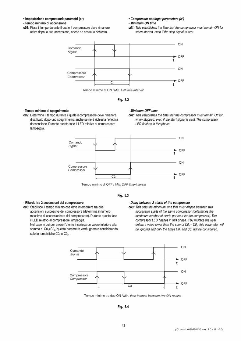
• Impostazione compressori: parametri (c*)- Tempo minimo di accensionec01: Fissa il tempo durante il quale il compressore deve rimanere
attivo dopo la sua accensione, anche se cessa la richiesta.
- Tempo minimo di spegnimentoc02: Determina il tempo durante il quale il compressore deve rimanere
disattivato dopo uno spegnimento, anche se ne è richiesta l’effettivariaccensione. Durante questa fase il LED relativo al compressorelampeggia.
- Ritardo tra 2 accensioni del compressorec03: Stabilisce il tempo minimo che deve intercorrere tra due
accensioni successive del compressore (determina il numeromassimo di accensioni/ora del compressore). Durante questa faseil LED relativo al compressore lampeggia.Nel caso in cui per errore l’utente inserisca un valore inferiore alla somma di C01+C02, questo parametro verrà ignorato considerandosolo le tempistiche C01 e C02.
• Compressor settings: parameters (c*)- Minimum ON timec01: This establishes the time that the compressor must remain ON for
when started, even if the stop signal is sent.
- Minimum OFF timec02: This establishes the time that the compressor must remain Off for
when stopped, even if the start signal is sent. The compressorLED flashes in this phase.
- Delay between 2 starts of the compressorc03: This sets the minimum time that must elapse between two
successive starts of the same compressor (determines themaximum number of starts per hour for the compressor). Thecompressor LED flashes in this phase. If by mistake the userenters a value lower than the sum of C01 + C02, this parameter willbe ignored and only the times C01 and C02 will be considered.
43µC2 - cod. +030220420 - rel. 2.0 - 18.10.04
Compressor
Signal
Min. ON time-interval
t
t
ComandoON
OFF
ON
OFF
Compressore
Tempo minimo di ON /
C1
Compressor
Signal
Min. OFF time-interval
t
t
ON
OFF
ON
OFF
Comando
Compressore
C2
Tempo minimo di OFF /
Compressor
Signal
Min. time-interval between two ON routins
t
t
ON
OFF
ON
OFF
Comando
Compressore
C3
Tempo minimo tra due ON /
Fig. 5.2
Fig. 5.3
Fig. 5.4
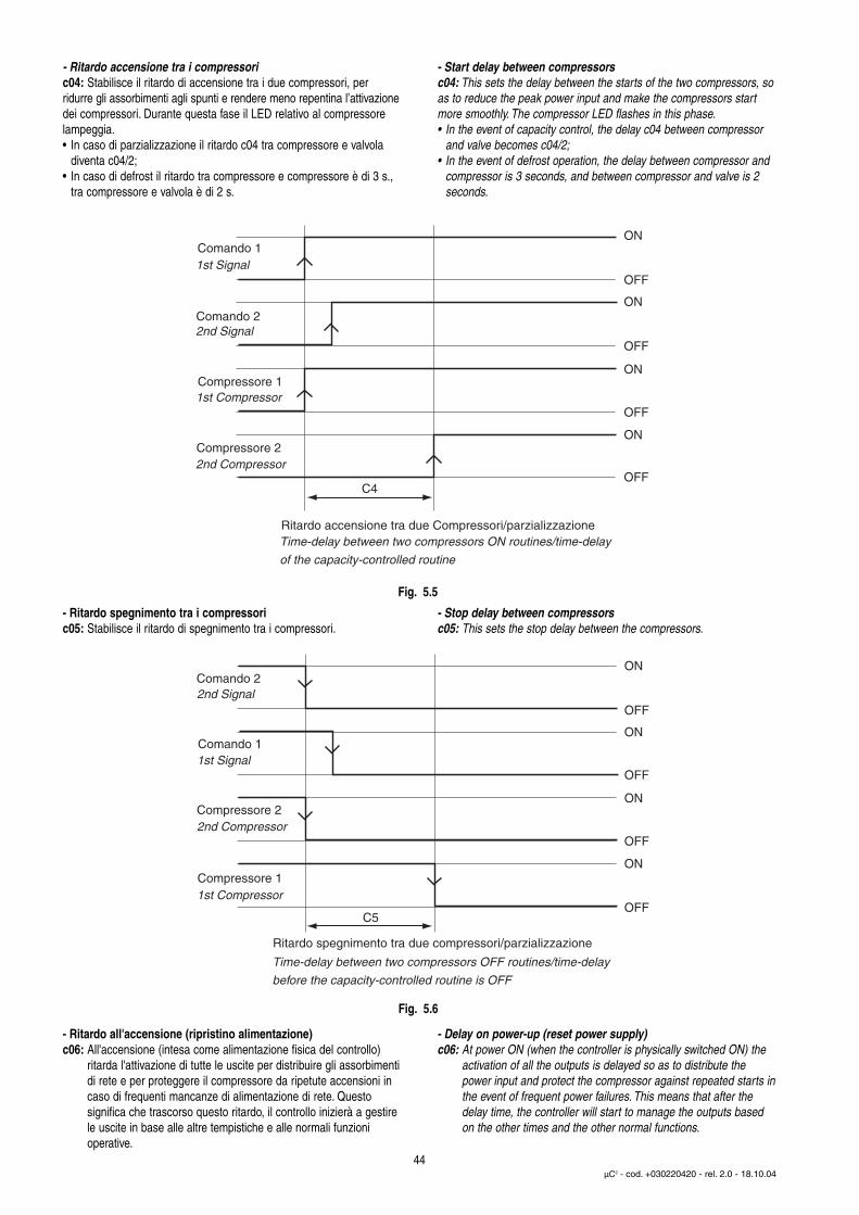
- Ritardo accensione tra i compressoric04: Stabilisce il ritardo di accensione tra i due compressori, perridurre gli assorbimenti agli spunti e rendere meno repentina l’attivazionedei compressori. Durante questa fase il LED relativo al compressorelampeggia.• In caso di parzializzazione il ritardo c04 tra compressore e valvola
diventa c04/2;• In caso di defrost il ritardo tra compressore e compressore è di 3 s.,
tra compressore e valvola è di 2 s.
- Ritardo spegnimento tra i compressoric05: Stabilisce il ritardo di spegnimento tra i compressori.
- Ritardo all'accensione (ripristino alimentazione)c06: All'accensione (intesa come alimentazione fisica del controllo)
ritarda l'attivazione di tutte le uscite per distribuire gli assorbimentidi rete e per proteggere il compressore da ripetute accensioni incaso di frequenti mancanze di alimentazione di rete. Questosignifica che trascorso questo ritardo, il controllo inizierà a gestire le uscite in base alle altre tempistiche e alle normali funzioni operative.
- Start delay between compressorsc04: This sets the delay between the starts of the two compressors, soas to reduce the peak power input and make the compressors startmore smoothly. The compressor LED flashes in this phase.• In the event of capacity control, the delay c04 between compressor
and valve becomes c04/2;• In the event of defrost operation, the delay between compressor and
compressor is 3 seconds, and between compressor and valve is 2 seconds.
- Stop delay between compressorsc05: This sets the stop delay between the compressors.
- Delay on power-up (reset power supply)c06: At power ON (when the controller is physically switched ON) the
activation of all the outputs is delayed so as to distribute thepower input and protect the compressor against repeated starts inthe event of frequent power failures. This means that after the delay time, the controller will start to manage the outputs based on the other times and the other normal functions.
44µC2 - cod. +030220420 - rel. 2.0 - 18.10.04
1st Signal
2nd Signal
1st Compressor
2nd Compressor
Time-delay between two compressors ON routines/time-delay
of the capacity-controlled routine
Comando 1ON
OFF
ON
OFF
ON
OFF
ON
OFF
Comando 2
Compressore 1
Compressore 2
Ritardo accensione tra due Compressori/parzializzazione
C4
Fig. 5.5
2nd Signal
1st Signal
2nd Compressor
1st Compressor
Time-delay between two compressors OFF routines/time-delay
before the capacity-controlled routine is OFF
ON
OFF
ON
OFF
ON
OFF
ON
OFF
Comando 1
Comando 2
Compressore 1
Compressore 2
Ritardo spegnimento tra due compressori/parzializzazione
C5
Fig. 5.6
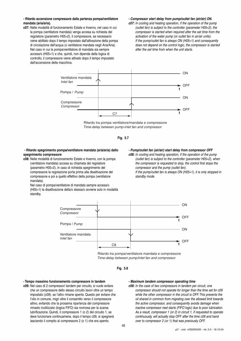
- Ritardo accensione compressore dalla partenza pompa/ventilatoremandata (aria/aria).c07: Nelle modalità di funzionamento Estate e Inverno, nel caso in cui
la pompa (ventilatore mandata) venga accesa su richiesta delregolatore (parametro H05=2), il compressore, se necessario viene abilitato dopo il tempo impostato dall'attivazione della pompadi circolazione dell'acqua (o ventilatore mandata negli Aria/Aria).Nel caso in cui la pompa/ventilatore di mandata sia sempreaccesa/o (H05=1) e che, quindi, non dipenda dalla logica dicontrollo, il compressore viene attivato dopo il tempo impostatodall'accensione della macchina.
- Ritardo spegnimento pompa/ventilatore mandata (aria/aria) dallospegnimento compressorec08: Nelle modalità di funzionamento Estate e Inverno, con la pompa
(ventilatore mandata) accesa su chiamata del regolatore(parametro H05=2), in caso di richiesta spegnimento delcompressore la regolazione porta prima alla disattivazione delcompressore e poi a quello effettivo della pompa (ventilatoremandata).Nel caso di pompa/ventilatore di mandata sempre accesa/o(H05=1) la disattivazione della/o stessa/o avviene solo in modalitàstandby.
- Tempo massimo funzionamento compressore in tandemc09: Nel caso di 2 compressori tandem per circuito, si vuole evitare
che un compressore dello stesso circuito lavori oltre un tempoimpostato (c09), se l’altro rimane spento. Questo per evitare chel’olio in comune, migri oltre il consentito verso il compressoreattivo, evitando che la prossima ripartenza del compressore rimasto inutilizzato (logica FIFO) sia rovinosa per la scarsalubrificazione. Quindi, il compressore 1 (o 2) del circuito 1, se deve funzionare continuamene, dopo il tempo c09, si spegnerà lasciando il compito al compressore 2 (o 1) che era spento.
- Compressor start delay from pump/outlet fan (air/air) ON.c07: In cooling and heating operation, if the operation of the pump
(outlet fan) is subject to the controller (parameter H05=2), thecompressor is started when required after the set time from theactivation of the water pump (or outlet fan in air/air units).If the pump/outlet fan is always ON (H05=1) and consequentlydoes not depend on the control logic, the compressor is startedafter the set time from when the unit starts.
- Pump/outlet fan (air/air) start delay from compressor OFFc08: In cooling and heating operation, if the operation of the pump
(outlet fan) is subject to the controller (parameter H05=2), whenthe compressor is requested to stop, the control first stops thecompressor and the pump (outlet fan).If the pump/outlet fan is always ON (H05=1), it is only stopped instandby mode.
- Maximum tandem compressor operating timec09: In the case of two compressors in tandem per circuit, one
compressor should not operate for longer than the time set for c09while the other compressor in the circuit is OFF. This prevents the oil shared in common from migrating over the allowed limit towardsthe active compressor, and consequently avoids damage when inactive compressor next starts (FIFO logic) due to poor lubrication.As a result, compressor 1 (or 2) in circuit 1, if requested to operatecontinuously, will actually stop OFF after the time c09 and handover to compressor 2 (or 1) that was previously OFF.
45µC2 - cod. +030220420 - rel. 2.0 - 18.10.04
Pump
Compressor
Time-delay between pump-inlet fan and compressor
Inlet fan
t
t
Pompa /
Ventilatore mandata
Compressore
Ritardo tra pompa ventilatore/mandata e compressore
C7
ON
OFF
ON
OFF
Pump
Inlet fan
Compressor
Time-delay between pump/inlet fan and compressor
t
t
Pompa /
Ventilatore mandata
C8
Compressore
Ritardo tra pompa/ventilatore mandata e compressore
ON
OFF
ON
OFF
Fig. 5.7
Fig. 5.8
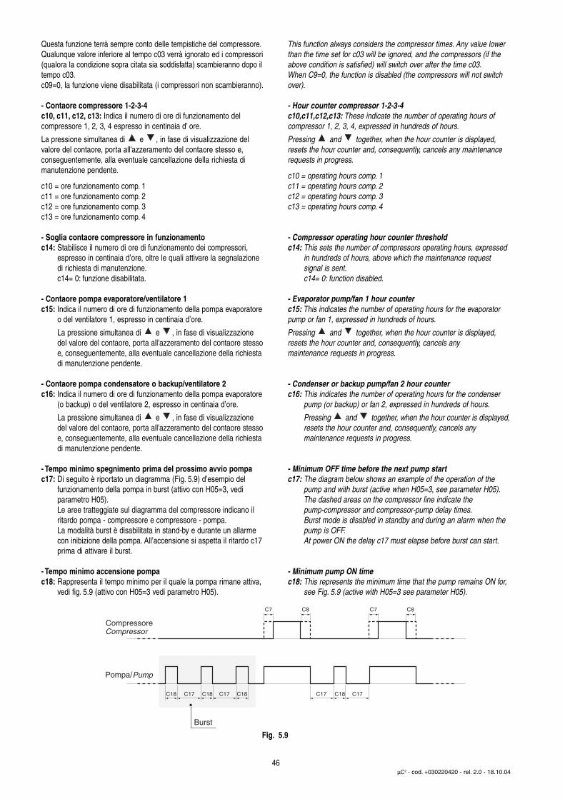
Questa funzione terrà sempre conto delle tempistiche del compressore.Qualunque valore inferiore al tempo c03 verrà ignorato ed i compressori(qualora la condizione sopra citata sia soddisfatta) scambieranno dopo iltempo c03.c09=0, la funzione viene disabilitata (i compressori non scambieranno).
- Contaore compressore 1-2-3-4c10, c11, c12, c13: Indica il numero di ore di funzionamento delcompressore 1, 2, 3, 4 espresso in centinaia d’ ore.
La pressione simultanea di e , in fase di visualizzazione delvalore del contaore, porta all'azzeramento del contaore stesso e,conseguentemente, alla eventuale cancellazione della richiesta dimanutenzione pendente.
c10 = ore funzionamento comp. 1c11 = ore funzionamento comp. 2c12 = ore funzionamento comp. 3c13 = ore funzionamento comp. 4
- Soglia contaore compressore in funzionamentoc14: Stabilisce il numero di ore di funzionamento dei compressori,
espresso in centinaia d’ore, oltre le quali attivare la segnalazionedi richiesta di manutenzione.c14= 0: funzione disabilitata.
- Contaore pompa evaporatore/ventilatore 1c15: Indica il numero di ore di funzionamento della pompa evaporatore
o del ventilatore 1, espresso in centinaia d’ore.
La pressione simultanea di e , in fase di visualizzazione del valore del contaore, porta all'azzeramento del contaore stessoe, conseguentemente, alla eventuale cancellazione della richiesta di manutenzione pendente.
- Contaore pompa condensatore o backup/ventilatore 2c16: Indica il numero di ore di funzionamento della pompa evaporatore
(o backup) o del ventilatore 2, espresso in centinaia d’ore.
La pressione simultanea di e , in fase di visualizzazione del valore del contaore, porta all'azzeramento del contaore stessoe, conseguentemente, alla eventuale cancellazione della richiesta di manutenzione pendente.
- Tempo minimo spegnimento prima del prossimo avvio pompac17: Di seguito è riportato un diagramma (Fig. 5.9) d’esempio del
funzionamento della pompa in burst (attivo con H05=3, vedi parametro H05).Le aree tratteggiate sul diagramma del compressore indicano ilritardo pompa - compressore e compressore - pompa.La modalità burst è disabilitata in stand-by e durante un allarme con inibizione della pompa. All’accensione si aspetta il ritardo c17prima di attivare il burst.
- Tempo minimo accensione pompac18: Rappresenta il tempo minimo per il quale la pompa rimane attiva,
vedi fig. 5.9 (attivo con H05=3 vedi parametro H05).
This function always considers the compressor times. Any value lowerthan the time set for c03 will be ignored, and the compressors (if theabove condition is satisfied) will switch over after the time c03.When C9=0, the function is disabled (the compressors will not switchover).
- Hour counter compressor 1-2-3-4c10,c11,c12,c13: These indicate the number of operating hours ofcompressor 1, 2, 3, 4, expressed in hundreds of hours.
Pressing and together, when the hour counter is displayed,resets the hour counter and, consequently, cancels any maintenancerequests in progress.
c10 = operating hours comp. 1c11 = operating hours comp. 2c12 = operating hours comp. 3c13 = operating hours comp. 4
- Compressor operating hour counter thresholdc14: This sets the number of compressors operating hours, expressed
in hundreds of hours, above which the maintenance requestsignal is sent.c14= 0: function disabled.
- Evaporator pump/fan 1 hour counterc15: This indicates the number of operating hours for the evaporatorpump or fan 1, expressed in hundreds of hours.
Pressing and together, when the hour counter is displayed,resets the hour counter and, consequently, cancels anymaintenance requests in progress.
- Condenser or backup pump/fan 2 hour counterc16: This indicates the number of operating hours for the condenser
pump (or backup) or fan 2, expressed in hundreds of hours.
Pressing and together, when the hour counter is displayed,resets the hour counter and, consequently, cancels anymaintenance requests in progress.
- Minimum OFF time before the next pump startc17: The diagram below shows an example of the operation of the
pump and with burst (active when H05=3, see parameter H05).The dashed areas on the compressor line indicate thepump-compressor and compressor-pump delay times.Burst mode is disabled in standby and during an alarm when the pump is OFF.At power ON the delay c17 must elapse before burst can start.
- Minimum pump ON timec18: This represents the minimum time that the pump remains ON for,
see Fig. 5.9 (active with H05=3 see parameter H05).
46µC2 - cod. +030220420 - rel. 2.0 - 18.10.04
Compressor
Pump
C7
Compressore
Pompa/
Burst
C18 C18C17 C17 C17 C17C18 C18
C8 C7 C8
Fig. 5.9
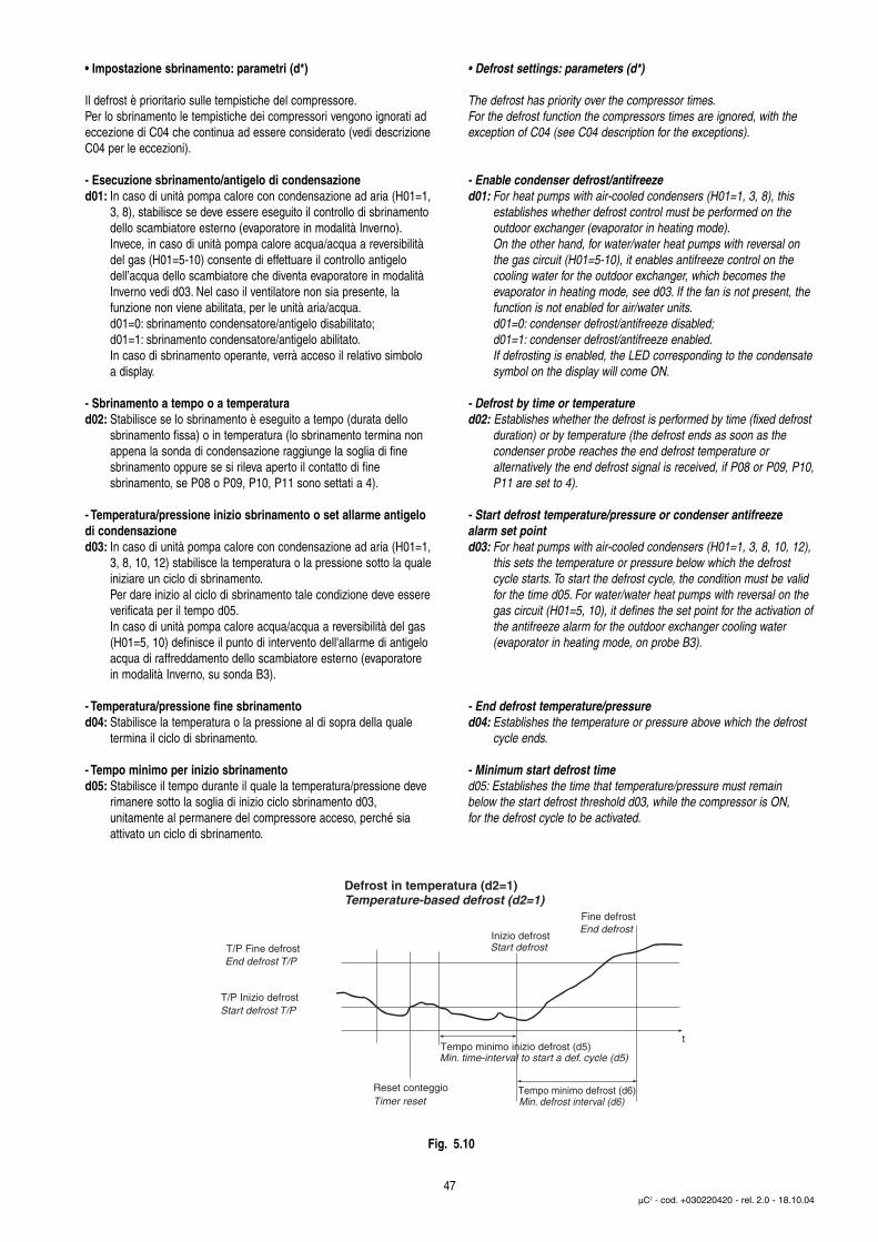
• Impostazione sbrinamento: parametri (d*)
Il defrost è prioritario sulle tempistiche del compressore.Per lo sbrinamento le tempistiche dei compressori vengono ignorati adeccezione di C04 che continua ad essere considerato (vedi descrizioneC04 per le eccezioni).
- Esecuzione sbrinamento/antigelo di condensazioned01: In caso di unità pompa calore con condensazione ad aria (H01=1,
3, 8), stabilisce se deve essere eseguito il controllo di sbrinamentodello scambiatore esterno (evaporatore in modalità Inverno).Invece, in caso di unità pompa calore acqua/acqua a reversibilitàdel gas (H01=5-10) consente di effettuare il controllo antigelo dell’acqua dello scambiatore che diventa evaporatore in modalità Inverno vedi d03. Nel caso il ventilatore non sia presente, la funzione non viene abilitata, per le unità aria/acqua.d01=0: sbrinamento condensatore/antigelo disabilitato;d01=1: sbrinamento condensatore/antigelo abilitato.In caso di sbrinamento operante, verrà acceso il relativo simbolo a display.
- Sbrinamento a tempo o a temperaturad02: Stabilisce se lo sbrinamento è eseguito a tempo (durata dello
sbrinamento fissa) o in temperatura (lo sbrinamento termina nonappena la sonda di condensazione raggiunge la soglia di finesbrinamento oppure se si rileva aperto il contatto di finesbrinamento, se P08 o P09, P10, P11 sono settati a 4).
- Temperatura/pressione inizio sbrinamento o set allarme antigelodi condensazioned03: In caso di unità pompa calore con condensazione ad aria (H01=1,
3, 8, 10, 12) stabilisce la temperatura o la pressione sotto la qualeiniziare un ciclo di sbrinamento.Per dare inizio al ciclo di sbrinamento tale condizione deve essereverificata per il tempo d05.In caso di unità pompa calore acqua/acqua a reversibilità del gas (H01=5, 10) definisce il punto di intervento dell'allarme di antigelo acqua di raffreddamento dello scambiatore esterno (evaporatore in modalità Inverno, su sonda B3).
- Temperatura/pressione fine sbrinamentod04: Stabilisce la temperatura o la pressione al di sopra della quale
termina il ciclo di sbrinamento.
- Tempo minimo per inizio sbrinamentod05: Stabilisce il tempo durante il quale la temperatura/pressione deve
rimanere sotto la soglia di inizio ciclo sbrinamento d03,unitamente al permanere del compressore acceso, perché siaattivato un ciclo di sbrinamento.
• Defrost settings: parameters (d*)
The defrost has priority over the compressor times.For the defrost function the compressors times are ignored, with theexception of C04 (see C04 description for the exceptions).
- Enable condenser defrost/antifreezed01: For heat pumps with air-cooled condensers (H01=1, 3, 8), this
establishes whether defrost control must be performed on theoutdoor exchanger (evaporator in heating mode).On the other hand, for water/water heat pumps with reversal onthe gas circuit (H01=5-10), it enables antifreeze control on thecooling water for the outdoor exchanger, which becomes the evaporator in heating mode, see d03. If the fan is not present, the function is not enabled for air/water units.d01=0: condenser defrost/antifreeze disabled;d01=1: condenser defrost/antifreeze enabled.If defrosting is enabled, the LED corresponding to the condensatesymbol on the display will come ON.
- Defrost by time or temperatured02: Establishes whether the defrost is performed by time (fixed defrost
duration) or by temperature (the defrost ends as soon as thecondenser probe reaches the end defrost temperature oralternatively the end defrost signal is received, if P08 or P09, P10,P11 are set to 4).
- Start defrost temperature/pressure or condenser antifreezealarm set pointd03: For heat pumps with air-cooled condensers (H01=1, 3, 8, 10, 12),
this sets the temperature or pressure below which the defrostcycle starts. To start the defrost cycle, the condition must be validfor the time d05. For water/water heat pumps with reversal on thegas circuit (H01=5, 10), it defines the set point for the activation ofthe antifreeze alarm for the outdoor exchanger cooling water(evaporator in heating mode, on probe B3).
- End defrost temperature/pressured04: Establishes the temperature or pressure above which the defrost
cycle ends.
- Minimum start defrost timed05: Establishes the time that temperature/pressure must remainbelow the start defrost threshold d03, while the compressor is ON,for the defrost cycle to be activated.
47µC2 - cod. +030220420 - rel. 2.0 - 18.10.04
Defrost in temperatura (d2=1) Temperature-based defrost (d2=1)
End defrost T/P
Start defrost T/P
Min. time-interval to start a def. cycle (d5)
Timer reset Min. defrost interval (d6)
Start defrost
End defrostFine defrost
T/P Fine defrostInizio defrost
T/P Inizio defrost
Reset conteggio
Tempo minimo inizio defrost (d5)t
Tempo minimo defrost (d6)
Fig. 5.10
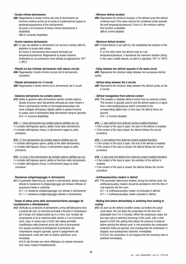
- Durata minima sbrinamentod06: Rappresenta la durata minima del ciclo di sbrinamento (la
funzione continua anche se la sonda di condensazione supera la temperatura/pressione di fine sbrinamento).Se posto a 0 la funzione di tempo minimo sbrinamento è disabilitatad06=0: comando disabilitato.
- Durata massima sbrinamentod07: In caso sia abilitato lo sbrinamento con termine a tempo (d02=0)
stabilisce la durata dello stesso.Se invece lo sbrinamento deve essere terminato per temperatura/pressione. Rappresenta la durata massima (trattandosi di una protezione viene attivata la segnalazione “dF1”o “dF2”).
- Ritardo tra due richieste sbrinamento nello stesso circuitod08: Rappresenta il ritardo minimo tra due cicli di sbrinamento
successivi.
- Ritardo sbrinamento tra i 2 circuitid09: Rappresenta il ritardo minimo tra lo sbrinamento dei 2 circuiti.
- Gestione sbrinamento da contatto esternod10: Abilita la gestione dello sbrinamento tramite contatto esterno.
Questa funzione viene tipicamente utilizzata per poter iniziare ofinire lo sbrinamento tramite un termostato/pressostato cheviene collegato all’ingresso digitale adibito a questa funzione.In questo caso le tempistiche degli sbrinamenti vengono ignorate.d10 = 0: funzione disabilitata.
d10 = 1: inizio sbrinamento da contatto esterno abilitato per cui:• il contatto dell’ingresso aperto, abilita l’inizio dello sbrinamento;• il contatto dell’ingresso chiuso, lo sbrinamento segue la solita
procedura.
d10 = 2: fine sbrinamento da contatto esterno abilitato per cui:• il contatto dell’ingresso aperto, abilita la fine dello sbrinamento;• il contatto dell’ingresso chiuso, lo sbrinamento segue la solita
procedura.
d10 = 3: inizio e fine sbrinamento da contatto esterno abilitato per cui:• il contatto dell’ingresso aperto, abilita la fine/inizio dello sbrinamento;• il contatto dell’ingresso chiuso, lo sbrinamento segue la solita
procedura.
- Resistenze antigelo/appoggio in sbrinamentod11: Il parametro determina se, durante lo sbrinamento, devono essere
attivate le resistenze di antigelo/appoggio per limitare l’afflusso diacqua/aria fredda in ambiente.d11 = 0: resistenze antigelo/appoggio non attivate in sbrinamento;d11 = 1: resistenze antigelo/appoggio attivate in sbrinamento.
- Tempo di attesa prima dello sbrinamento/ritardo passaggio dariscaldamento a raffreddamentod12: Verificata la condizione di sbrinamento, prima dell’attivazione vera
e propria del ciclo, la macchina provvede a fermare il compressoreper il tempo d12 (selezionabile da 0 a 3 min). Con l’arresto delcompressore si ha la rotazione delle valvole a 4 vie (inversioneciclo), dopo un tempo pari a d12/2; tale attesa permettel’equilibratura delle pressioni prima del ciclo di sbrinamento.Con questa procedura le tempistiche di protezione del compressore vengono ignorate, quindi lo spegnimento del compressore, come del resto la relativa ripartenza, sono immediate.d12=0: tale fermata non viene effettuata e la valvola inversioneciclo viene ruotata immediatamente.
- Minimum defrost durationd06: Represents the minimum duration of the defrost cycle (the defrost
continues even if the value read by the condenser probe exceedsthe end temperature/pressure). If set to 0, the minimum defrosttime function is disabled.d06=0: control disabled.
- Maximum defrost durationd07: If timed defrost is set (d02=0), this establishes the duration of the
cycle.If, on the other hand, the defrost ends at a set temperature/pressure, it represents the maximum duration (beingin this case a safety feature, an alarm is signalled, “dF1” or “dF2”).
- Delay between two defrost requests in the same circuitd08: Represents the minimum delay between two successive defrostcycles.
- Defrost delay between the 2 circuitsd09: Represents the minimum delay between the defrost cycles on the
2 circuits.
- Defrost management from external contactd10: This enables or disables defrost control from an external contact.
This function is typically used to end the defrost based on a signalfrom a thermostat/pressure switch connected to thecorresponding digital input. In this case, the defrost times areignored.d10 = 0: function disabled
d10 = 1: start defrost from external contact enabled therefore:• if the contact of the input is open, the start of the defrost is enabled;• if the contact of the input closed, the defrost follows the normal
procedure.
d10 = 2: end defrost from external contact enabled therefore:• if the contact of the input is open, the end of the defrost is enabled;• if the contact of the input is closed, the defrost follows the normal
procedure.
d10 = 3: start and end defrost from external contact enabled therefore:• if the contact of the input is open, the end/start of the defrost is
enabled;• if the contact of the input is closed, the defrost follows the normal
procedure.
- Antifreeze/auxiliary heaters in defrostd11: This parameter determines whether, during the defrost cycle, the
antifreeze/auxiliary heaters should be activated to limit the flow ofcold water/air into the room.d11 = 0: antifreeze/auxiliary heater not activated in defrost;d11 = 1: antifreeze/auxiliary heater activated in defrost.
- Waiting time before defrost/delay in switching from heating tocoolingd12: As soon as the defrost condition arises, but before the actual
cycle starts, the unit stops the compressor for the time d12(selectable from 0 to 3 minutes). When the compressor stops, thefour-way valve is switched (reversing of the cycle), after a timeequal to d12/2; this waiting time allows the pressure to balancebefore starting the defrost cycle. In this procedure the compressorprotection times are ignored, and consequently the compressor isstopped, and subsequently restarted, immediately.If d12=0, the compressor is not stopped and the reversing valve isswitched immediately.
48µC2 - cod. +030220420 - rel. 2.0 - 18.10.04
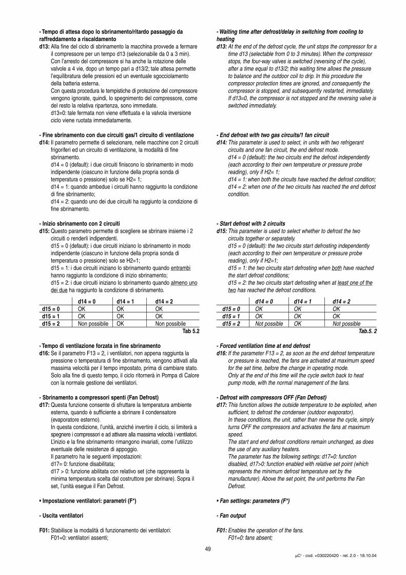
- Tempo di attesa dopo lo sbrinamento/ritardo passaggio da raffreddamento a riscaldamentod13: Alla fine del ciclo di sbrinamento la macchina provvede a fermare
il compressore per un tempo d13 (selezionabile da 0 a 3 min).Con l’arresto del compressore si ha anche la rotazione dellevalvole a 4 vie, dopo un tempo pari a d13/2; tale attesa permettel’equilibratura delle pressioni ed un eventuale sgocciolamentodella batteria esterna.Con questa procedura le tempistiche di protezione del compressorevengono ignorate, quindi, lo spegnimento del compressore, come del resto la relativa ripartenza, sono immediate.d13=0: tale fermata non viene effettuata e la valvola inversioneciclo viene ruotata immediatamente.
- Fine sbrinamento con due circuiti gas/1 circuito di ventilazioned14: Il parametro permette di selezionare, nelle macchine con 2 circuiti
frigoriferi ed un circuito di ventilazione, la modalità di finesbrinamento.d14 = 0 (default): i due circuiti finiscono lo sbrinamento in modoindipendente (ciascuno in funzione della propria sonda ditemperatura o pressione) solo se H2= 1;d14 = 1: quando ambedue i circuiti hanno raggiunto la condizionedi fine sbrinamento;d14 = 2: quando uno dei due circuiti ha raggiunto la condizione difine sbrinamento.
- Inizio sbrinamento con 2 circuitid15: Questo parametro permette di scegliere se sbrinare insieme i 2
circuiti o renderli indipendenti.d15 = 0 (default): i due circuiti iniziano lo sbrinamento in modoindipendente (ciascuno in funzione della propria sonda ditemperatura o pressione) solo se H2=1;d15 = 1: i due circuiti iniziano lo sbrinamento quando entrambihanno raggiunto la condizione di inizio sbrinamento;d15 = 2: i due circuiti iniziano lo sbrinamento quando almeno unodei due ha raggiunto la condizione di sbrinamento.
d14 = 0 d14 = 1 d14 = 2d15 = 0 OK OK OKd15 = 1 OK OK OKd15 = 2 Non possibile OK Non possibile
Tab 5.2
- Tempo di ventilazione forzata in fine sbrinamentod16: Se il parametro F13 = 2, i ventilatori, non appena raggiunta la
pressione o temperatura di fine sbrinamento, vengono attivati allamassima velocità per il tempo impostato, prima di cambiare stato.Solo alla fine di questo tempo, il ciclo ritornerà in Pompa di Calorecon la normale gestione dei ventilatori.
- Sbrinamento a compressori spenti (Fan Defrost)d17: Questa funzione consente di sfruttare la temperatura ambiente
esterna, quando è sufficiente a sbrinare il condensatore(evaporatore esterno).In questa condizione, l’unità, anziché invertire il ciclo, si limiterà a spegnere i compressori e ad attivare alla massima velocità i ventilatori.L’inizio e la fine sbrinamento rimangono invariati, come l’utilizzo eventuale delle resistenze di appoggio.Il parametro ha le seguenti impostazioni:d17= 0: funzione disabilitata;d17 > 0: funzione abilitata con relativo set (che rappresenta laminima temperatura scelta dal costruttore per sbrinare). Sopra ilset, l’unità esegue il Fan Defrost.
• Impostazione ventilatori: parametri (F*)
- Uscita ventilatori
F01: Stabilisce la modalità di funzionamento dei ventilatori:F01=0: ventilatori assenti;
- Waiting time after defrost/delay in switching from cooling toheatingd13: At the end of the defrost cycle, the unit stops the compressor for a
time d13 (selectable from 0 to 3 minutes). When the compressorstops, the four-way valves is switched (reversing of the cycle),after a time equal to d13/2; this waiting time allows the pressureto balance and the outdoor coil to drip. In this procedure thecompressor protection times are ignored, and consequently thecompressor is stopped, and subsequently restarted, immediately.If d13=0, the compressor is not stopped and the reversing valve isswitched immediately.
- End defrost with two gas circuits/1 fan circuitd14: This parameter is used to select, in units with two refrigerant
circuits and one fan circuit, the end defrost mode.d14 = 0 (default): the two circuits end the defrost independently (each according to their own temperature or pressure probe reading), only if H2= 1;d14 = 1: when both the circuits have reached the defrost condition;d14 = 2: when one of the two circuits has reached the end defrostcondition.
- Start defrost with 2 circuitsd15: This parameter is used to select whether to defrost the two
circuits together or separately.d15 = 0 (default): the two circuits start defrosting independently (each according to their own temperature or pressure probe reading), only if H2=1;d15 = 1: the two circuits start defrosting when both have reachedthe start defrost conditions;d15 = 2: the two circuits start defrosting when at least one of thetwo has reached the defrost conditions.
d14 = 0 d14 = 1 d14 = 2d15 = 0 OK OK OKd15 = 1 OK OK OKd15 = 2 Not possible OK Not possible
Tab.5. 2
- Forced ventilation time at end defrostd16: If the parameter F13 = 2, as soon as the end defrost temperature
or pressure is reached, the fans are activated at maximum speedfor the set time, before the change in operating mode.Only at the end of this time will the cycle switch back to heatpump mode, with the normal management of the fans.
- Defrost with compressors OFF (Fan Defrost)d17: This function allows the outside temperature to be exploited, when
sufficient, to defrost the condenser (outdoor evaporator).In these conditions, the unit, rather than reverse the cycle, simply turns OFF the compressors and activates the fans at maximum speed.The start and end defrost conditions remain unchanged, as does the use of any auxiliary heaters.The parameter has the following settings: d17=0: function disabled, d17>0: function enabled with relative set point (which represents the minimum defrost temperature set by the manufacturer). Above the set point, the unit performs the Fan Defrost.
• Fan settings: parameters (F*)
- Fan output
F01: Enables the operation of the fans.F01=0: fans absent;
49µC2 - cod. +030220420 - rel. 2.0 - 18.10.04

F01=1: ventilatori presenti.L’uscita PWM (1 o 2 a seconda del parametro H02) richiede lapresenza delle schede opzionali di gestione dei ventilatori(ON/OFF per modulo CONVONOFF o variazione di velocità perMCHRTF o FCS trifase).
- Modalità funzionamento ventilatoriF02: Stabilisce la logica di funzionamento dei ventilatori:
F02=0: sempre accesi alla massima velocità, indipendentementedai compressori. I ventilatori vengono spenti solo nel caso in cuila macchina è in stand-by.F02=1: accesi alla massima velocità quando è attivo almeno uncompressore del circuito relativo (funzionamento in parallelo perciascun circuito).F02=2: accesi quando è attivo il relativo compressore, conregolazione ON/OFF rispetto alle temperature/pressioni di minimae massima velocità (parametri F05-F06-F08-F09).Quando i compressori si spengono i ventilatori relativi si disattivanoindipendentemente dalla temperatura/pressione di condensazione.
F02=3: accesi quando è attivo il relativo compressore con regolazionedi velocità. Quando i compressori si spengono i ventilatori relativi sidisattivano indipendentemente dalla temperatura/pressione dicondensazione.
Con F02=3 e sonda di condensazione di tipo NTC, all’accensione delcompressore si ha lo spunto dei ventilatori alla massima velocità per iltempo F11, indipendentemente dalla temperatura misurata.In caso di sonda di condensazione guasta, i ventilatori verranno spenti.
- Soglia tensione minima per TriacF03: Nell’eventualità di regolazione di velocità dei ventilatori è richiesta
la presenza delle schede opzionali a taglio di fase MCHRTF*/FCS(dotate di Triac). In tal caso è necessario specificare le tensionierogate dal Triac al motore elettrico del ventilatore, corrispondentialla minima e massima velocità. Il valore impostato non corrispondeall’effettiva tensione in Volt applicata ma ad una unità di calcolointerna al µC2.F03 = Rappresenta la soglia minima per il triac
F01=1: fans present.The PWM output (1 or 2, depending on the value of parameterH02) requires the presence of the optional fan control cards(ON/OFF for the CONVONOFF module or speed variation forMCHRTF or FCS three-phase).
- Fan operating modeF02: This establishes the operating logic for the fans:
F02=0: always ON at maximum speed, independently from thecompressors. The fans are only switched OFF when the unit is instandby.F02=1: ON at maximum speed when at least one compressor inthe corresponding circuit is ON (parallel operation in each circuit).F02=2: ON when the corresponding compressor is ON, withON/OFF control based on the temperature/pressure settings forthe minimum and maximum speed (parameters F05-F06-F08and F09). When the compressors are stopped, the correspondingfans are also stopped, irrespective of the condensingtemperature/pressure.
F02=3: ON when the corresponding compressor is ON, with speedcontrol. When the compressors are stopped the corresponding fans arealso stopped, irrespective of the condensing temperature/pressure.
With F02=3 and an NTC condenser probe, when the compressor startsthe fans are started at maximum speed for the time F11, irrespective ofthe temperature measured.In the event of a condenser probe fault, the fans will be switched OFF.
- Minimum voltage threshold for TriacF03: In the event of fan speed control, the optional phase cutting cards
(MCHRTF*) are required, fitted with a triac. The voltage deliveredby the triac to the electric fan motor corresponding to theminimum speed must be set. The set value does not correspondto the actual voltage in Volts applied, but rather to an internal unitof calculation in the µC2.F03 = Represents the minimum threshold for the triac
50µC2 - cod. +030220420 - rel. 2.0 - 18.10.04
% speed
Condensingtemperature/pressure
F04
F05
F06 F09
F04
F08
Velocità %
Tempo/presscondensazione
Condensingtemperature/pressure
Tempo/presscondensazione
ESTATE/COOLINGON/OFF
INVERNO/HEATINGON/OFF
0%
100%
% speedVelocità %
0%
100%
Fig. 5.11
histeresis
F04
F03
F05
F07 F06
histeresis
F04
F03
F08
F09 F10Condensingtemperature/pressure
Tempo/presscondensazione
Condensingtemperature/pressure
Tempo/presscondensazione
ESTATE/COOLINGREG. VEL.
INVERNO/HEATINGREG. VEL.
% speedVelocità %
0%
100 %
0%
isteresi isteresi
Fig. 5.12
- Soglia tensione massima per TriacF04: Nell’eventualità di regolazione di velocità dei ventilatori è richiesta
la presenza delle schede opzionali a taglio di fase MCHRTF*(dotate di Triac). In tal caso è necessario specificare la tensioneerogata dal Triac al motore elettrico del ventilatore corrispondentealla massima velocità. Il valore impostato non corrispondeall’effettiva tensione in Volt applicata ma ad una unità di calcolointerna al µC2.F04 = Rappresenta la soglia massima per il triac
- Set temperatura/pressione minima velocità in modalità Estate(raffreddamento)F05: Determina la temperatura o la pressione sotto la quale i ventilatori
permangono alla minima velocità.Nel caso di regolazione ON/OFF rappresenta la temperatura o la pressione sotto la quale i ventilatori vengono spenti (Fig. 5.11).
- Differenziale Temperatura/pressione massima velocità inmodalità Estate (raffreddamento)F06: Nel caso si utilizzi il regolatore di velocità, rappresenta il
differenziale rispetto ad F05 della temperatura o pressione soprala quale i ventilatori devono essere attivate alla massima velocità;nel caso di regolazione ON/OFF rappresenta il differenzialesopra il quale i ventilatori vengono accesi (Fig. 5.11).
- Differenziale temperatura/pressione per spegnimento in modalitàEstate (raffreddamento)F07: Nel caso si utilizzi il regolatore di velocità, rappresenta il
differenziale, rispetto ad F05, per la temperatura o la pressionesotto il quale i ventilatori si spengono. (Fig. 5.12) Nel caso in cui, per il controllo della condensazione, si utilizzino sonde di temperatura NTC o sonde di pressione, l’accensione presenta una isteresi, rispettivamente, di 1 °C o 0,5 bar.
- Set temperatura/pressione minima velocità in modalità Inverno(riscaldamento)F08: Determina la temperatura o la pressione sopra la quale i
ventilatori devono essere attivati alla minima velocità (Fig 5.12).Nel caso di regolazione ON/OFF rappresenta la temperatura o la pressione sopra la quale i ventilatori vengono spenti (Fig 5.11).
- Differenziale temperatura/pressione massima velocità ventilatoriin modalità Inverno (riscaldamento)F09: Nel caso si utilizzi il regolatore di velocità, rappresenta il differenziale,
rispetto ad F08, per la temperatura o la pressione sotto il quale i ventilatori vengono attivati alla massima velocità (Fig 5.12).Nel caso di regolazione ON/OFF rappresenta il differenzialesotto il quale i ventilatori vengono accesi (Fig. 5.11).
- Differenziale temperatura/pressione spegnimento ventilatori inmodalità Inverno (riscaldamento)F10: Nel caso si utilizzi il regolatore di velocità per i ventilatori,
rappresenta il differenziale, rispetto ad F08, della temperatura odella pressione sopra la quale i ventilatori vengono spenti. (Fig. 5.12)Nel caso in cui, per il controllo della condensazione, si utilizzino sonde di temperatura NTC o sonde di pressione, l’accensione presenta una isteresi, rispettivamente, di 1 °C o 0,5 bar.
- Tempo di spunto ventilatoriF11: Stabilisce il tempo di funzionamento alla massima velocità
all'accensione dei ventilatori per vincere le inerzie meccaniche delmotore. La stessa tempistica viene rispettata anche all’accensionedel compressore (indipendentemente dalla temperatura/pressionedel condensatore), nel caso siano selezionate sonde di temperatura NTC per il controllo della condensazione e sia abilitata la regolazione di velocità F02=3); ciò avviene al fine di anticipare l’aumento improvviso di pressione (a cui non corrispondenecessariamente un altrettanto rapido aumento di temperatura nella zona ove è posta la sonda) e di conseguenza migliorare la regolazione
- Maximum voltage threshold for TriacF04: In the event of fan speed control, the optional phase cutting cards
(MCHRTF*) are required, fitted with a triac. The voltage deliveredby the triac to the electric fan motor corresponding to themaximum speed must be set. The set value does not correspondto the actual voltage in Volts applied, but rather to an internal unitof calculation in the µC2.F04 = Represents the maximum threshold for the triac
- Temperature/pressure set point for minimum speed in coolingF05: This represents the temperature or pressure below which the fans
remain ON at minimum speed.In the case of ON/OFF control, it represents the temperature or pressure below which the fans are switched OFF (Fig.5.11).
- Temperature/pressure differential for maximum speed in coolingF06: This represents the temperature or pressure differential in
reference to F05 above which the fans are started at maximumspeed; in the case of ON/OFF control, this represents the differential above which the fans are started (Fig. 5.11).
- Temperature/pressure differential for fans Off in coolingF07: This represents the temperature or pressure differential in
reference to F05 below which the fans are stopped. The fans arestarted 1 °C “lower” when using NTC temperature probes, or 0. 5bars if using pressure probes.When using NTC temperature or pressure probes for condenser control, the fans are started with an hysteresis of 1 ºC or 0. 5 bar
- Temperature/pressure set point for minimum speed in heatingF08: This represents the temperature or pressure above which the fans
are started at minimum speed (Fig 5.12).In the case of ON/OFF control, it represents the temperature or pressure above which the fans are switched OFF (Fig.5.11)
- Temperature/pressure differential for maximum speed in heatingF09: If fan speed control is used, this represents the temperature or
pressure differential in reference to F08 below which the fans arestarted at maximum speed (Fig 5.12).in the case of ON/OFF control, this represents the differential below which the fans are started (Fig. 5.11).
- Temperature/pressure differential for fans Off in heatingF10: If fan speed control is used, this represents the temperature or
pressure differential in reference to F08 above which the fans arestopped. The fans are started 1 °C “lower” if using NTCtemperature probes or 0. 5 bars lower if using pressure probes.When using NTC temperature or pressure probes for condenser control, the fans are started with an hysteresis of 1 ºC or 0. 5 bar.
- Fan start timeF11: This establishes the operating time at maximum speed when the
fans are started, so as to overcome the mechanical inertia of themotor.The same times are observed in reference to the start of thecompressor (irrespective of the condensing temperature/pressure),if NTC temperature probes are used on the condenser and speedcontrol is enabled, F02=3; this is done to bring forward the suddenincrease in pressure (which does not necessarily correspond to a likewise rapid increase in temperature in the area where the probeis located) and consequently to improve control
51µC2 - cod. +030220420 - rel. 2.0 - 18.10.04

F11=0: la funzione non viene eseguita (disabilitata), ovvero i ventilatorivengono attivati alla minima velocità e, poi, controllati in basealla temperatura/pressione di condensazione.
- Durata impulso TriacF12: Rappresenta la durata, in millisecondi, dell’impulso applicato al triac.
Per motori con comportamento induttivo impostare il parametro a 2 (default). Invece usando i moduli CONVONOFF0 o CONV0/10A0,impostare il parametro a 0.
- Gestione ventilatori in modalità sbrinamentoF13: Questo parametro imposta la logica di funzionamento dei
ventilatori di condensazione durante lo sbrinamento.:
F11=0: the function is disabled, that is, the fans are activated at theminimum speed and then controlled based on the condensingtemperature/pressure.
- Triac impulse durationF12: This represents the duration in milliseconds for the impulse
applied to the triac. For induction motors, set the parameter to 2 (default). On the other hand, when using the CONVONOFF0 or CONV0/10A0 modules, set the parameter to 0.
- Fan management mode in defrostF13: This parameter sets the operating logic for the condensing fans
during the defrost phase:52
µC2 - cod. +030220420 - rel. 2.0 - 18.10.04
???? ???
8
8 10108
98
F02= 2 F02= 3
F02= 3 F02= 3
Fig. 5.13 Fig. 5.14
Fig. 5.15 Fig. 5.16

F13 = 0: (default) i ventilatori sono disattivati.F13 = 1: i ventilatori sono attivi come in modalità chiller(raffreddamento) rispetto alla temperatura o pressione.F13 = 2: i ventilatori sono disattivati, fino alla pressione otemperatura di fine sbrinamento, al di sopra della quale vengonoaccesi alla massima velocità per il tempo impostato nel parametrod16. Solo alla fine di questo tempo, il ciclo ritornerà in pompa dicalore con la normale gestione dei ventilatori.
Nota: Nel caso la macchina stia effettuando il Fan Defrost (parametrod17), la gestione dei ventilatori selezionata da F13 é disabilitata.
• Impostazione macchina: parametri: (H*)
- Modello di macchinaH01:Permette di selezionare il tipo di macchina da controllare:
H01= 0: unità aria/ariaH01= 1: Pompa di Calore aria/ariaH01= 2: Chiller aria/acquaH01= 3: Pompa di Calore aria/acquaH01= 4: Chiller acqua/acquaH01= 5: Pompa di Calore acqua/acqua a rev. del gas (*)H01= 6: Pompa di Calore acqua/acqua a rev. dell’ acqua (*)H01= 7: motocondensante ad ariaH01= 8: motocondensante ad aria ad inversione del ciclo del gasH01= 9: motocondensante ad acquaH01= 10: motocondensante ad acqua a reversibilità del gas
(*) Nota: Impostare H21= 4 (Pompa condensazione sempre accesa),se H02= 1 (Due condensatori).
- Numero circuiti di ventilazione di condensazione/condensatoriad acquaH02:Stabilisce il numero di circuiti di ventilazione presenti nella
configurazione a due circuiti. Con 1 circuito di ventilazione (H02=0) la macchina può avere 1 o 2 circuiti frigo:• con 1 circuito frigo, il controllo dei ventilatori viene fatto
esclusivamente in base al valore di pressione/temperatura delsensore relativo al primo circuito;
• con 2 circuito circuiti frigo, il controllo dei ventilatori fa riferimentoalla temperatura/pressione più alta dei due circuiti.In Pompa di Calore l’uscita dipende dalla temperatura o pressione più bassa. L’ uscita di comando sarà Y1.Viceversa, con 2 circuiti di ventilazione (H02=1) ogni uscita PWM è indipendente ed in funzione della propria sonda dicondensazione (B3 o B4 per il circuito 1 e B7 o B8 per il circuito 2).
- Numero evaporatoriH03: Stabilisce il numero di evaporatori presenti quando vi sono 2 o 4
compressori, ovviamente con 2 circuiti (include l’espansione). Conun evaporatore (H03=0), la gestione resistenze e il controllo antigeloè eseguito solo su B2. Viceversa, con 2 evaporatori (H03=1) il controllo antigelo sarà affidato alla sonda B2 e alla sonda B6, mentreper il controllo dell’acqua in uscita, sarà utilizzato l’ingresso B5.
- Numero compressori/circuitiH04:Stabilisce il numero di compressori per circuito ed il numero dei
circuiti. Per dettaglio parametri vedi Tab. 4.3.7.
- Modalità di funzionamento pompa evaporatore/ventilatoreH05: Stabilisce la modalità di funzionamento della pompa di circolazione
dell'acqua nell’evaporatore o del ventilatore di mandata (nelle unità Aria/Aria). H05 = 0: pompa disabilitata, (l'allarme flussostato viene ignorato) H05 = 1: sempre accesa (l’allarme viene gestito)H05 = 2: accesa su chiamata del compressore (l’allarme viene gestito)H05 = 3: la pompa sarà attivata con intervalli regolari di ON e OFF(indipendentemente dai compressori) come da impostazione Burst(vedi parametri c17 e c18). Alla richiesta di caldo o freddo parte prima la pompa evaporatore/ventilatore mandata in modalità fissa (sempre ON) e, poi, il compressore dopo i tempi impostati (c07, c08).La pompa non verrà spenta se tutti i compressori non sono stati spenti.
Attenzione: con macchine ad aria H01=0,1 se si utilizzano resistenze per il
F13 = 0: (default) the fans are OFF.F13 = 1: the fans are ON as in cooling mode, based on thetemperature or pressure.F13 = 2: the fans are OFF until the end defrost temperature orpressure is reached, above which they are started at maximumspeed for the time set for parameter d16. Only at the end of thistime will the cycle return to heat pump mode with the normalmanagement of the fans.
Note: If the unit is running the Fan Defrost function (parameter d17),the fan management selected by F13 is disabled.
• Unit settings: parameters: (H*)
- Unit modelH01:Used to select the type of unit being controlled:
H01= 0: air/air unitsH01= 1: AIR/AIR heat pumpH01= 2: AIR/WATER ChillerH01= 3: AIR/WATER heat pumpH01= 4:WATER/WATER ChillerH01= 5: water/water heat pump with rev. on gas (*)H01= 6: water/water heat pump with rev. on water (*)H01= 7: air-cooled condensing unitH01= 8: air-cooled condensing unit with reversal on gas circuitH01= 9: water-cooled condensing unitH01= 10: water-cooled unit condensing with reversal on gas circuit
(*) Note: Set H21= 4 (Condenser pump always on), if H02= 1 (Two condensers).
- Number of condenser fan circuits/water condensersH02:This establishes the number of fan circuits present in the
configurations with two circuits. With one fan circuit (H02=0) theunit may have 1 or 2 refrigerant circuits:• with one refrigerant circuit, the fans are exclusively controlled
based on the pressure or temperature read by the sensor in thefirst circuit;
• with two refrigerant circuits, the fans are controlled based on thehigher temperature/pressure of the two circuits. In heat pumpmode, the output depends on the lower temperature or pressure.The output used is Y1.Vice-versa, with 2 ventilation circuits (H02=1) each PWM output is independent and depends on its own condenser probe (B3 or B4 for circuit 1 and B7 or B8 for circuit 2).
- Number of evaporatorsH03:This establishes the number of evaporators present when there are 2
or 4 compressors, obviously with 2 circuits (including the expansion).With one evaporator (H03=0), the management of the heaters andthe antifreeze function is performed only on B2. Vice-versa, with 2evaporators (H03=1) antifreeze control will be performed using B2and B6, while input B5 is used to control the water outlet temperature.
- Number of compressors/circuitsH04:This establishes the number of compressors per circuit and the
number of circuits. For further details see Table 4.3.7.
- Evaporator pump/fan operating modeH05:This establishes the operating mode for the evaporator water
pump or the outlet fan (in air/air units).H05 = 0: pump disabled, (the flow switch alarm is ignored)H05 = 1: always ON (the alarm is managed)H05 = 2: ON when called by compressor (the alarm is managed)H05 = 3: the pump will be started and stopped at regular intervals(independently from the compressors) as per the Burst setting(see parameters c17 and c18). When the heating or cooling signalis received, first the evaporator pump/outlet fan starts (always ON),and then the compressor, after the set times (c07, c08). The pumpwill not be stopped until all the compressors are Off.
Note: with air/air units (H01=0,1), if heaters are used as the heating53
µC2 - cod. +030220420 - rel. 2.0 - 18.10.04

riscaldamento bisogna assolutamente evitare che il ventilatore si fermimentre il riscaldamento è attivo, per evitare possibili rischi d’incendio.Pertanto se H01=0 o 1, si deve selezionare H05=1.
- Ingresso digitale Estate/Inverno.H06:Stabilisce se la selezione Estate/Inverno da ingresso digitale è
abilitata o meno (vedi parametri P08, P09, P10, P11, P12 e P13).Lo stato aperto forza la macchina in funzionamento Estate, viceversa, modalità Inverno.D-IN Aperto = EstateD-IN Chiuso = Inverno
- Ingresso digitale ON/OFFH07:Stabilisce se la selezione ON/OFF da ingresso digitale è abilitata
o meno. Se la selezione è abilitata (H07= 1) lo stato “aperto” forzala macchina a spegnersi mentre con lo stato “chiuso” la macchinapuò essere spenta o accesa anche da tastiera.
- Configurazione rete µC2
H08:Stabilisce la struttura della rete tLan.0 = solo µC2
1 = µC2 + valvola2 = µC2 + exp.3 = µC2+ exp. + valvola
- Abilitazione tastieraH09:Permette di disabilitare la modifica dei parametri DIRECT e USER
da tastiera ma consente comunque la visualizzazione del valore dei parametri. Vengono disabilitate anche le funzioni abilitazione/disabilitazione Estate/Inverno e reset contatori.Stato Tastiera:0: disabilitata1: abilitata (default)
- Indirizzo serialeH10: Stabilisce l'indirizzo dello strumento per il collegamento seriale, tramite
scheda opzionale, ad un sistema di supervisione e/o teleassistenza.
- Selezione mappa usciteH11:Questo parametro permette di associare arbitrariamente alcune
uscite digitali agli organi dell’unità.
H11= 0: standard (default); per unità con un compressore per circuito (H04=0, 2).
Uscite Associazione agli organi dell’unitàC1 Compressore 1C2 Resistenza 1C3 Pompa/(ventilatore) evaporatore (se unità aria/aria)C4 Valvola inversione ciclo 1C5 AllarmeC6 Compressore 2C7 Resistenza 2C8 Pompa condensazione/backupC9 Valvola inversione ciclo 2C10 Avviso
Tab 5.3
H11= 1: Per unità solo freddo bicompressore (H01=0, 2, 4, 7, 9, e H04=1, 3, 5)
Uscite Associazione agli organi dell’unitàC1 Compressore 1C2 Resistenza 1C3 Pompa/(ventilatore) evaporatore (se unità aria/aria)C4 Compressore 2 (o parzializzazione comp. 1)C5 AllarmeC6 Compressore 3C7 Resistenza 2C8 Pompa condensazione/backupC9 Compressore 4 (o parzializzazione comp. 2)C10 Avviso
Tab.5.4
device, the fan must not be stopped while heating is active. This wouldcause the risk of fire. Therefore, if H01=0 or 1, H05 must be set to 1.
- Cooling/heating digital input.H06:Establishes whether the cooling/heating selection from digital
input is enabled. see parameters P08, P09, P10, P11, P12 and P13). The open status places the unit in cooling operation, vice-versa, in heating.D-IN Open = CoolingD-IN Closed = Heating
- ON/OFF digital inputH07:Establishes whether the ON/OFF selection from digital input is
enabled or disabled. If the selection is enabled (H07= 1), the“open” status switches the unit Off, while in the “closed” status, theunit may be OFF or ON, as controlled by the keypad.
- µC2 network configurationH08:Establishes the layout of the tLan network.
0 = µC2 only1 = µC2 + valve2 = µC2 + exp.3 = µC2 + exp. + valve
- Enable keypadH09:Used to disable the modification of the DIRECT and USER
parameters from the keypad. The value of the parameters can always be displayed. The enable/disable cooling, heating and reset counter functions are also available.Values:0: keypad disabled1: keypad enabled (default)
- Serial addressH10: Establishes the address of the instrument for the serial connection,
via an optional board, to a PC for supervision and/or telemaintenance.
- Selection map outputsH11:This parameter is used to arbitrarily associate some digital
outputs to the devices on the unit.
H11= 0: standard (default); for units with one compressor per circuit (H04=0, 2).
Outputs Associated deviceC1 Compressor 1C2 Heater 1C3 Pump/evaporator (fan) (on air/air units)C4 Reversing valve 1C5 AlarmC6 Compressor 2C7 Heater 2C8 Condenser pump/backupC9 Reversing valve 2C10 Warning
Tab 5.3
H11= 1: For cooling only units with two compressors (H01=0, 2, 4, 7, 9and H04=1, 3, 5)
Outputs Associated deviceC1 Compressor 1C2 Heater 1C3 Pump/evaporator (fan) (on air/air units)C4 Compressor 2 (or capacity control comp. 1)C5 AlarmC6 Compressor 3C7 Heater 2C8 Condenser pump/backupC9 Compressor 4 (or capacity control comp. 2)C10 Warning
Tab 5.4
54µC2 - cod. +030220420 - rel. 2.0 - 18.10.04
H11= 2: Le uscite dell’espansione seguiranno la medesima logica per il 2° circuito. Per H01= 1, 3,5, 6, 8, 10 e H04= 1, 3, 5
Uscite Associazione agli organi dell’unitàC1 Compressore 1C2 Resistenza 1C3 Pompa/(ventilatore) evaporatore (se unità aria/aria)C4 Compressore 2 (o parzializzazione comp. 1)C5 Valvola inversione ciclo 1C6 Compressore 3C7 Resistenza 2C8 Pompa condensazione/backupC9 Compressore 4 (o parzializzazione comp. 2)C10 Valvola inversione ciclo 2
Tab.5.5
H11= 3: Le uscite dell’espansione seguiranno la medesima logica per il 2º circuito. Per H01= 1, 3,5, 6, 8, 10 e H04= 1, 3, 5
Uscite Associazione agli organi dell’unitàC1 Compressore 1C2 Valvola inversione ciclo 1C3 Pompa/(ventilatore) evaporatore (se unità aria/aria)C4 Compressore 2 (o parzializzazione comp. 1)C5 AllarmeC6 Compressore 3C7 Valvola inversione ciclo 2C8 Pompa condensazione/backupC9 Compressore 4 (o parzializzazione comp. 2)C10 Avviso
Tab.5.6
H11= 4: Per H01= 1, 3,5, 6, 8, 10 e H04= 0, 1
Uscite Associazione agli organi dell’unitàC1 Compressore 1C2 Valvola inversione ciclo 1C3 Pompa evaporatore C4 Compressore 2 (o parzializzazione comp. 1)C5 Allarme C6 - non usatoC7 Resistenza 1C8 Pompa condensazione/backupC9 - non usatoC10 Avviso
Tab.5.7
H11= 5: Per unità solo freddo bicompressore (H01= 0, 2, 4, 7, 9, e H04= 0)
Uscite Associazione agli organi dell’unitàC1 Compressore 1C2 Resistenza 1C3 Pompa/(ventilatore) evaporatore (se unità aria/aria)C4 Ventilatore condensazione 1C5 AllarmeC6 Compressore 2C7 Resistenza 2C8 Pompa condensazione/backupC9 Ventilatore condensazione 2C10 Avviso
Tab.5.8
- Logica parzializzazioneH12:Specifica la logica di attivazione delle parzializzazioni per i
compressori e per la valvola d’inversione a 4 vie.H12 = 0: valvola inversione a 4 vie e parzializzazioni normalmenteeccitateH12 = 1: valvola inversione a 4 vie e parzializzazioni normalmentediseccitate. Valore di default.H12 = 2: valvola inversione a 4 vie n. disecc. e parzializzazioni n.ecc.H12 = 3: valvola inversione a 4 vie n. ecc. e parzializzazioni n. disecc.
Nota: in caso di parzializzazione, la rotazione tra compressore erelativa valvola é disabilitata. La logica FIFO o a tempo potrà essereutilizzata tra i 2 circuiti per ottimizzare gli spunti o le ore dei 2compressori (1 per circuito).
H11= 2: The outputs of the expansion follow the same logic for the 2nd circuit. For H01= 1, 3, 5, 6, 8, 10 and H04= 1, 3, 5
Outputs Associated deviceC1 Compressor 1C2 Heater 1C3 Pump/evaporator (fan) (on air/air units)C4 Compressor 2 (or capacity control comp. 1)C5 Reversing valve 1C6 Compressor 3C7 Heater 2C8 Condenser pump/backupC9 Compressor 4 (or capacity control comp. 2)C10 Reversing valve 2
Tab.5. 5
H11= 3 The outputs of the expansion follow the same logic for the 2nd circuit. For H01= 1, 3, 5, 6, 8, 10 and H04= 1, 3, 5
Outputs Associated deviceC1 Compressor 1C2 Reversing valve 1C3 Pump/evaporator (fan) (on air/air units)C4 Compressor 2 (or capacity control comp. 1)C5 AlarmC6 Compressor 3C7 Reversing valve 2C8 Condenser pump/backupC9 Compressor 4 (or capacity control comp. 2)C10 Warning
Tab.5. 6
H11= 4: For H01= 1, 3, 5, 6, 8, 10 and H04= 0, 1
Output Associated deviceC1 Compressor 1C2 Reversing valve 1C3 Evaporator pump C4 Compressor 2 (or capacity-control comp. 1)C5 Alarm C6 - not usedC7 Heater 1C8 Condenser pump/backupC9 - not usedC10 Warning
Table 5.7
H11= 5: For cooling only units with two compressors (H01= 0, 2, 4, 7, 9, and H04= 0)
Output Associated deviceC1 Compressor 1C2 Heater 1C3 Evaporator pump/(fan) (for air/air units)C4 Condenser fan 1C5 AlarmC6 Compressor 2C7 Heater 2C8 Condenser pump/backupC9 Condenser fan 2C10 Warning
Table 5.8
- Capacity-control logicH12:Specifies the logic for the activation of the capacity-control steps
for the compressors and the 4-way reversing valve.H12 = 0: 4-way reversing valve and capacity-control normally energisedH12 = 1: 4-way reversing valve and capacity-control normally de-energised. Default value.H12 = 2: 4-way reversing valve normally de-energised and capacity-control normally energisedH12 = 3: 4-way reversing valve normally energised and capacity-control normally de-energised.
Note: in the event of capacity-control, the rotation between compressorand corresponding valve is disabled. FIFO or time logic can be usedbetween the 2 circuits to optimise the starts or the operating hours ofthe 2 compressors (1 per circuit)
55µC2 - cod. +030220420 - rel. 2.0 - 18.10.04
- Funzione seconda pompaH21:Questo parametro definisce come l’uscita dedicata alla seconda
pompa debba essere gestita.H21= 0: la seconda pompa viene disabilitata.H21= 1: la seconda pompa serve solo da Backup.
Se interviene il flussostato che attiva l’allarme, le pompevengono scambiate:• se l’allarme rientra, viene generato un avviso a display
e viene eccitato il relè di avviso, mentre l’unità continuaa funzionare con la pompa di Backup.Al prossimo allarme le pompe verranno ruotate.
• se l’allarme rimane attivo anche con la seconda pompa, dopo il tempo P01, viene generato l’allarmegenerale e l’unità viene spenta.
H21= 2: la seconda pompa rappresenta una pompa di Backup.Le 2 pompe non sono mai usate contemporaneamente ma ogni 24 ore vengono alternate.In caso di allarme flussostato, vale la stessa logica per l’impostazione 1. Dopo un scambio dovuto all’allarme flusso, il timer delle 24 ore viene azzerato.
H21= 3: la seconda pompa viene utilizzata come ON/OFF con lastessa modalità del ventilatore di condensazione (che inquesto caso non è presente) in modalità ON/OFF con glistessi set (di fatto in questo caso la pompa sostituisce ilventilatore compreso il simbolo).
H21= 4: la seconda pompa viene utilizzata per la condensazionema è sempre accesa. Il questo caso il simbolo dellapompa non viene gestito.
Nota: In caso di allarme flusso a ripristino automatico si effettuano 10tentativi di riavvio pompa ogni 90 s, per il tempo massimo di P02; dopo10 tentativi l’allarme diventa a ripristino manuale. Con la secondapompa il tentativo consiste nello scambio della pompa in funzione, conla stessa logica.
- Disabilitazione caricamento defaultH22: Questo parametro se posto a 1 disabilita la possibilità di ripristinare
i parametri di default tramite il tasto Prg premuto al ripristino tensione.
• Impostazione allarmi: parametri (P*)
- Ritardo allarme flussostato all'avviamento pompaP01: Stabilisce un ritardo nel riconoscimento dell'allarme del flussostato
all'avviamento della pompa (si attende che la portata arrivi a regime).In caso di allarme i compressori devono essere spenti immediatamente, ignorando le tempistiche.
- Ritardo allarme flussostato a regimeP02: Stabilisce un ritardo nel riconoscimento dell'allarme del flussostato
a regime, per filtrare eventuali variazioni di portata o bolle d'ariapresenti nel circuito dell'acqua. In caso di allarme i compressori devono essere spenti immediatamente, ignorando le tempistiche.
- Ritardo allarme bassa pressione alla partenza compressoreP03: Stabilisce un ritardo nel riconoscimento dell'allarme di bassa
pressione alla partenza del compressore per permettere ilraggiungimento di una situazione di regime. Questo ritardo viene rispettato anche all'inversione della valvola a 4 vie nel circuito del gas.
- Ripristino allarmiP05: Abilita il ripristino automatico per tutti quegli allarmi che sono
normalmente a ripristino manuale (alta pressione, bassa pressione,flussostato/antigelo) secondo la tabella di seguito riportata:
P05= 0: alta pressione, bassa pressione e antigelo(default) (bassa temperatura) a ripristino manualeP05= 1: tutti gli allarmi a ripristino automaticoP05= 2: alta pressione e antigelo (bassa temperatura) in
manuale, bassa pressione in automaticoP05= 3: alta pressione in manuale, bassa pressione e antigelo
(bassa temperatura) in automatico
- Function of the second pumpH21:This parameter defines how the output dedicated to the second
pump must be managed.H21= 0: 0, the second pump is disabled.H21= 1: 1, the second pump is used only as a backup.
If the flow switch and corresponding alarm are activated,the pumps are switched over:• if the alarm passes, a warning is shown on the display
and the warning relay is activated, while the unitcontinues to operate with the Backup pump. When the next alarm is activated the pumps will be switched over.
• if the alarm remains active even with the second pumpon for longer than the time set for P1, the generic alarmis generated and the unit is switched OFF.
H21= 2: the second pump represents a backup pump.The two pumps are never used at the same time but each 24 hours, are switched over. In the event of flow alarms, the logic is the same as for setting 1.After being switched over due to the flow alarm, the 24-hour timer is set to zero.
H21= 3: the second pump is used as an ON/OFF device in the sameway as the condenser fan (which in this case is notpresent), in ON/OFF mode, with the same settings (in fact in this case the pump replaces the fan, including thesymbol).
H21= 4: the second pump is used for the condenser but is alwaysON. In this case the pump symbol is not managed.
Note: In the event of flow alarms with automatic reset, 10 attempts aremade to restart the pump every 90 seconds, for a maximum time ofP02; after the 10 attempts, the alarm becomes manual reset. With thesecond pump, the attempt consists in switching over the pump that ison, with the same logic.
- Disable load default valuesH22: If this parameter is set to 1, it disables the possibility of restoring
the default parameters using the PRG button at power ON.
• Alarm settings: parameters (P*)
- Flow switch alarm delay when starting pumpP01: Establishes a delay in the recognition of the flow switch alarm
when starting the pump (this allows the flow-rate to stabilise). Inthe event of alarms, the compressors are stopped immediately,ignoring the times.
- Flow switch alarm delay in steady operationP02: Establishes a delay in the recognition of the flow switch alarm in
steady operation, so as to filter any variations in flow-rate or airbubbles present in the water circuit. In the event of alarms, thecompressors are stopped immediately, ignoring the times.
- Low pressure alarm delay at compressor startP03: Establishes a delay in the recognition of the low pressure alarm
when the compressor starts, so as to allow stable operatingconditions to be reached. This delay is also counted whenreversing the 4-way valve in the refrigerant circuit.
- Alarm resetP05: Enables automatic reset for all those alarms that normally feature
manual reset (high pressure, low pressure, flow switch /antifreeze) as per the following table:
P05= 0: high pressure, low pressure and antifreeze (low(default) temperature) with manual resetP05= 1: all the alarms with automatic resetP05= 2: high pressure and antifreeze (low temperature) manual,
low pressure automaticP05= 3: high pressure manual, low pressure and antifreeze (low
temperature) automatic
56µC2 - cod. +030220420 - rel. 2.0 - 18.10.04

P05= 4: alta e bassa pressione in manuale, antigelo (bassatemperatura) in automatico
P05= 5: alta e bassa pressione in manuale al terzo intervento inun’ora*, antigelo (bassa temperatura) in automatico
P05= 6: alta e bassa pressione in manuale al terzo intervento inun’ora*, antigelo (bassa temperatura) in manuale
Tab. 5.9
*gli allarmi di alta e bassa pressione sono gestiti allo stesso modo siaper i trasduttori sia per i pressostati (ingresso digitale); se l’unità è instand-by il conteggio (3 volte in un’ora) viene resettato.
- Logica Estate/InvernoP06: Con tale parametro impostato ad 1 si inverte anche la logica di
funzionamento della selezione Estate/Inverno (sia da tastiera cheda telecomando e da ingresso digitale).
Simbolo P06=0 P06=1Estate (Chiller) Inverno (pompa calore)
Inverno (pompa Estate (Chiller)calore)
Tab.5.10
- Allarme di bassa pressione con sonde di pressioneP07: P07=0: tale funzione viene disabilitata.
P07=1: se in modalità pompa calore la pressione dell’evaporatore(scambiatore esterno) è inferiore ad 1 bar (e se abilitata la presenzadella sonda di condensazione in pressione) viene attivato l’allarmedi bassa pressione (mantenendo comunque l’eventuale ritardo P03).
-Selezione ingresso digitale ID1P08= 0: nessunoP08= 1: flussostato con ripristino manuale (normalmente chiuso)P08= 2: flussostato con ripristino automatico (N.C.)P08= 3: termico generale con ripristino manuale (N.C.)P08= 4: termico generale con ripristino automatico (N.C.)P08= 5: termico circuito 1 con ripristino manuale (N.C.)P08= 6: termico circuito 1 con ripristino automatico (N.C.)P08= 7: termico circuito 2 con ripristino manuale (N.C.)P08= 8: termico circuito 2 con ripristino automatico (N.C.)P08= 9: Estate/Inverno (aperto = Estate, chiuso = Inverno)P08= 10: Estate/Inverno con ritardi d12 e d13 (aperto = Estate,
chiuso = Inverno)P08= 11: segnalazione allarme con ripristino manuale (N.C.)P08= 12: segnalazione allarme con ripristino automatico (N.C.)P08= 13: secondo set-poit da contatto esterno (sia estivo che
invernale), (normalmente aperto)P08= 14: secondo Set-Point estivo da contatto esterno ed
invernale da fascia oraria (N.A.)P08= 15: fine defrost da contatto esterno circuito 1 (N.C.)P08= 16: fine defrost da contatto esterno circuito 2 (N.C.)P08= 17: inizio defrost da contatto esterno circuito 1 (N.C.)P08= 18: inizio defrost da contatto esterno circuito 2 (N.C.)P08= 19: step 1 motocondensante (N.A.)P08= 20: step 2 motocondensante (N.A.)P08= 21: step 3 motocondensante (N.A.)P08= 22: step 4 motocondensante (N.A.)
Tab. 5.11
nota 1: nel caso P08 sia impostato a 10, il cambio di stato considera itempi d12 e d13, e rispetta i tempi di protezione dei compressori, siaesso dipeso dall'ingresso digitale, sia da tastiera.nota 2: nel caso l'ingresso digitale venga utilizzato per l' ON/OFF od ilcambio stagione, la tastiera viene disabilitata inibita a tali funzioni.
- Selezione ingressi digitali ID2, ID6, ID7, ID10P09, P10, P11, P12: Configurazione rispettivamente degli ingressi digitaliID2, ID6, ID7 e ID10 (come da tabella sopra per ingresso digitale ID1).Nota: Non è possibile impostare estate/inverno (9,10) su P10, P11,P12, e P14.
P05= 4: high and low pressure manual, antifreeze (lowtemperature) automatic
P05= 5: high and low pressure manual after the third activation inone hour*, antifreeze (low temperature) automatic
P05= 6: high and low pressure manual after the third activation inone hour*, antifreeze (low temperature) manual
Tab. 5.9
* the high and low pressure alarms are managed in the same way bothfor the transducers and the pressure switches (digital input); if the unitis in standby the count (3 times in one hour) is reset.
- Cooling/Heating logicP06: If this parameter is set to 1, the operating logic of the
Cooling/Heating logic is reversed (from the keypad, the remotecontrol and the digital input).
Symbol P06=0 P06=1Cooling (Chiller) Heating (heat pump)
Heating(heat pump) Cooling (Chiller)
Tab. 5.10
- Low pressure alarm with pressure probesP07: P07=0: this function is disabled.
P07=1: if in heat pump mode the evaporator (external exchanger)pressure is less than 1 bar (and if the presence of the condenserpressure probe is enabled), the low pressure alarm is activated(while still considering the delay P03).
- Select digital input ID1P08= 0: noneP08= 1: flow switch with manual reset (normally closed)P08= 2: flow switch with automatic reset (NC)P08= 3: general thermal overload with manual reset (NC)P08= 4: general thermal overload with automatic reset (NC)P08= 5: thermal overload circuit 1 with manual reset (NC)P08= 6: thermal overload circuit 1 with automatic reset (NC)P08= 7: thermal overload circuit 2 with manual reset (NC)P08= 8: thermal overload circuit 2 with automatic reset (NC)P08= 9: cooling/heating (open = Cooling, closed = Heating)P08= 10: cooling/heating with delays d12 and d13 (open =
Cooling, closed = Heating)P08= 11: alarm signal with manual reset (NC)P08= 12: alarm signal with automatic reset (NC)P08= 13: second set point from external contact (cooling
and heating), (normally open)P08= 14: second cooling set point from external contact and
heating from time band (NO)P08= 15: end defrost from external contact circuit 1 (NC)P08= 16: end defrost from external contact circuit 2 (NC)P08= 17: start defrost from external contact circuit 1 (NC)P08= 18: start defrost from external contact circuit 2 (NC)P08= 19: condenser step 1 (NO)P08= 20: condenser step 2 (NO)P08= 21: condenser step 3 (NO)P08= 22: condenser step 4 (NO)
Tab. 5.11
note 1: if P08 is set to 10, the change in state considers the times d12and d13, and respects the compressor protection times, both from thedigital input and the keypad.note 2: if the digital input is used to switch the unit ON/OFF or changethe operating mode, these functions are disabled on the keypad.
- Select digital inputs ID2,ID6,ID7,ID10P09, P10, P11, P12: Configuration of digital inputs ID2, ID6, ID7 andID10 respectively (as per the above table for digital input ID1).Note: cooling/heating (9,10) cannot be set on P10, P11, P12, and P14.
57µC2 - cod. +030220420 - rel. 2.0 - 18.10.04
- Selezione ingresso B4 se /04 = 1P13: Se l’ingresso B4 è utilizzato come ON/OFF (/04 = 1) valgono le
stesse opzioni di P08.
- Selezione ingresso B8 se /08 = 1P14: Se l’ingresso B8 è utilizzato come ON/OFF (/08 = 1) valgono le
stesse opzioni di P08.
- Selezione allarme bassa pressioneP15: Permette di selezionare se l’allarme di bassa pressione deve
essere rilevato anche a compressore spento (P15=1) oppure solocon compressore attivo (P15=0, default).Alla partenza del compressore l’allarme rimane in ogni caso disattivo per il tempo P03.
Set allarme di alta temperatura/alta temperatura avvio impiantoP16: Rappresenta una soglia d’allarme alta temperatura rilevata dalla
sonda B1; il differenziale è fisso a 2 °C ed il suo ripristino èautomatico (si attiva il relè di avviso, sola segnalazione e comparel’indicazione “Ht”).All’avvio dell’impianto tale allarme è inibito per il tempo P17. Se è abilitata la protezione avvio impianto (vedi parametro P20) e interviene l’allarme, il tempo P17 viene ignorato e l’allarme è privodi isteresi.
- Ritardo allarme alta temperatura all’accensioneP17: Ritardo allarme alta temperatura all’accensione del controllo
(power ON), da ON/OFF remoto o da tastiera.
- Set allarme di alta pressione da trasduttoreP18: Imposta il valore oltre il quale viene generato l’allarme di alta pressione.
Ciascun circuito sarà gestito in funzione del proprio trasduttore.P18= 0: la funzione è disabilitata.Per ciascun altro valore superiore a 3.0 per via dell’isteresi che èdi 3 bar, viene gestito l’allarme in funzione del set.
- Set allarme di bassa temperatura avvio impiantoP19: Rappresenta una soglia d’allarme bassa temperatura (rilevata dalla
sonda B1) priva di isteresi; il suo ripristino è automatico (il relè diallarme non viene attivato e appare a display la segnalazione “ALt”).
- Protezione avvio impianto per alta/bassa temperaturaP20: Questo parametro se impostato a 1, abilita la funzione di
protezione impianto all’avvio, al ripristino dell’alimentazione edal passaggio da Stand-by a ON.In modalità chiller (raffreddamento estivo) per valori di B1 superiori al set P16, l’unità è in allarme e non viene avviata (visualizzazione “AHt”). In modalità Pompa di Calore (riscaldamento invernale) per valoriinferiori al set P19 l’unità è in allarme e non viene avviata(visualizzazione “ALt”). Il suo ripristino è automatico.P20=0: la funzione non viene abilitata.
• Impostazione regolazione: parametri (r*)
- Set point estivo (raffreddamento)r01: compreso tra r13 e r14r02: differenziale estivo (raffreddamento)
- Setpoint invernale (riscaldamento: Pompa di Calore)r03: compreso tra r15 e r16r04: differenziale invernale (riscaldamento)
- Rotazione compressorir05: La rotazione dei compressori permette di ripartire equamente i
tempi di funzionamento in modo statistico per la logica FIFO e inmodo assoluto per il conteggio delle ore effettive di lavoro.Impostazioni del parametro:r05=0: rotazione disabilitata.Il cliente potrà utilizzare secondo la propria logica compressori di potenze differenti o gestire così la parzializzazione,
- Select input B4 if /04 = 1P13: If input B4 is used as ON/OFF (/04 = 1) the same options are
valid as for P08.
- Select input B8 if /08 = 1P14: If input B8 is used as ON/OFF (/08 = 1) the same options are
valid as for P08.
- Select low pressure alarmP15: Used to select whether the low pressure alarm is detected when
the compressor is OFF (P15=1) or alternatively only when thecompressor is ON (P15=0, default).When the compressor starts the alarm is in any case ignored for the time P03.
High temperature/high system start-up temperature alarm delayP16: Represents the high temperature alarm threshold detected by
probe B1; the differential is set at 2 °C and the alarm is resetautomatically (the warning relay is activated, signal only, and themessage “Ht” is shown).When starting the system, this alarm is ignored for the time P17.Ifthe system start-up protection is enabled (see parameter P20) and the alarm is activated, the time P17 is ignored and the alarm has no hysteresis.
- High temperature alarm delay on power-upP17: High temperature alarm delay when the control is switched on
(power ON), from the remote ON/OFF contact or from the keypad.
- High pressure alarm from transducer set pointP18: Sets the value beyond which the high pressure alarm is
generated. Each circuit will be managed by its own transducer.P18= 0: the function is disabled.For all other values greater than 3.0, due to the hysteresis (3bars), the alarm is managed according to the set value.
- Low system start-up temperature alarm set pointP19: Represents a threshold for the low temperature (measured by probe
B1) alarm, without hysteresis; it is reset automatically (the alarm relay is not activated and the display shows the message “ALt”).
- System start-up protection for high/low temperatureP20: If set to 1, this parameter enables the system protection function when
starting, both at power ON and when switching ON from Standby.In chiller mode (cooling), for values of B1 greater than the setpoint P19, an alarm is activated and the unit is not started(display “AHt”).In heat pump mode (heating), for values lower than the set pointP19, an alarm is activated and the unit is not started (display “ALt”).The alarm is reset automatically.P20=0: the function is not enabled.
• Control settings: parameters (r*)
- Cooling set pointr01: between r13 and r14r02: cooling differential
- Heating set point (heat pump)r03: between r15 and r16r04: heating differential
- Compressor rotationr05: The rotation of the compressors allows the operating hours to be
balanced either statistically, using FIFO logic, or absolutely, bycounting the effective operating hours.Settings:r05=0: rotation disabled; The customer can use compressors with different power ratings according to the desired logic or manage the capacity-control functions. The compressors are
58µC2 - cod. +030220420 - rel. 2.0 - 18.10.04
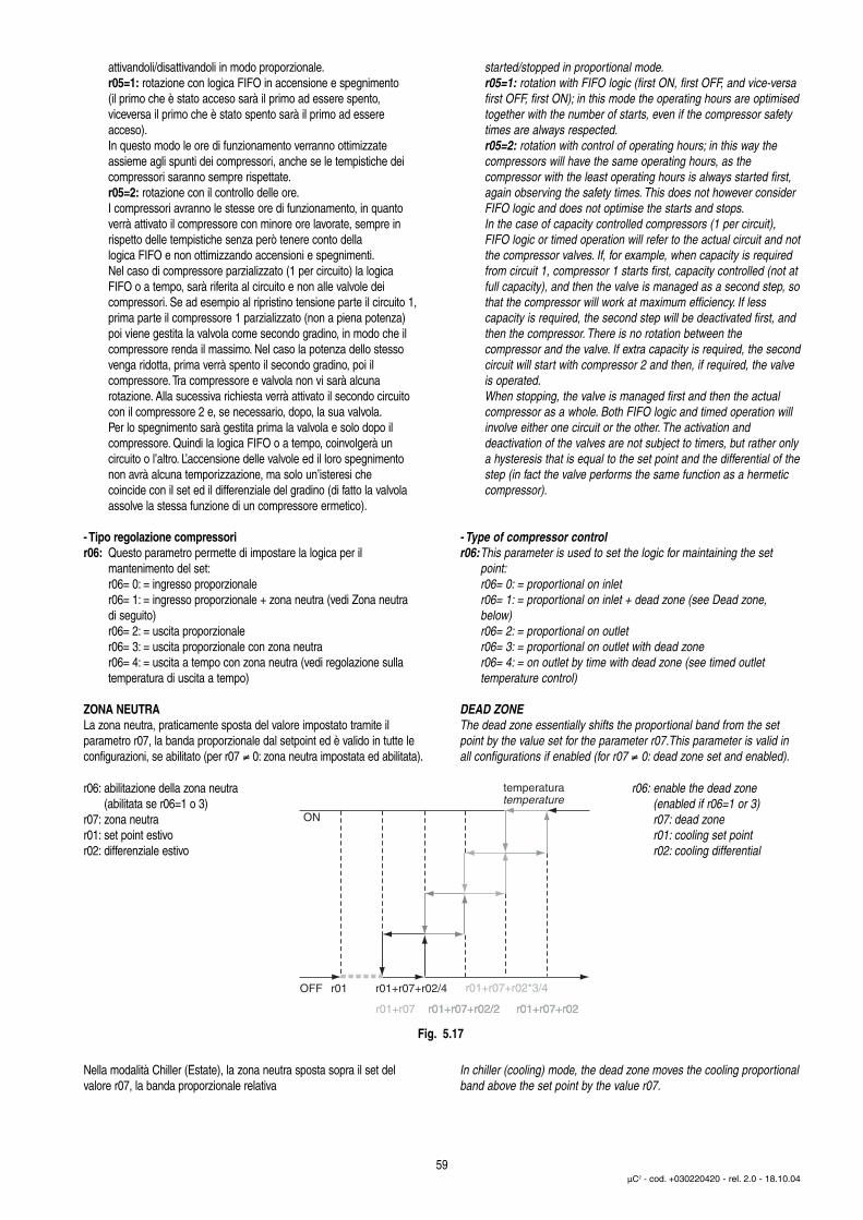
attivandoli/disattivandoli in modo proporzionale.r05=1: rotazione con logica FIFO in accensione e spegnimento(il primo che è stato acceso sarà il primo ad essere spento,viceversa il primo che è stato spento sarà il primo ad essereacceso).In questo modo le ore di funzionamento verranno ottimizzate assieme agli spunti dei compressori, anche se le tempistiche dei compressori saranno sempre rispettate.r05=2: rotazione con il controllo delle ore.I compressori avranno le stesse ore di funzionamento, in quantoverrà attivato il compressore con minore ore lavorate, sempre inrispetto delle tempistiche senza però tenere conto dellalogica FIFO e non ottimizzando accensioni e spegnimenti.Nel caso di compressore parzializzato (1 per circuito) la logicaFIFO o a tempo, sarà riferita al circuito e non alle valvole deicompressori. Se ad esempio al ripristino tensione parte il circuito 1,prima parte il compressore 1 parzializzato (non a piena potenza)poi viene gestita la valvola come secondo gradino, in modo che ilcompressore renda il massimo. Nel caso la potenza dello stessovenga ridotta, prima verrà spento il secondo gradino, poi ilcompressore.Tra compressore e valvola non vi sarà alcunarotazione. Alla sucessiva richiesta verrà attivato il secondo circuitocon il compressore 2 e, se necessario, dopo, la sua valvola.Per lo spegnimento sarà gestita prima la valvola e solo dopo ilcompressore. Quindi la logica FIFO o a tempo, coinvolgerà uncircuito o l’altro. L’accensione delle valvole ed il loro spegnimentonon avrà alcuna temporizzazione, ma solo un’isteresi checoincide con il set ed il differenziale del gradino (di fatto la valvolaassolve la stessa funzione di un compressore ermetico).
- Tipo regolazione compressorir06: Questo parametro permette di impostare la logica per il
mantenimento del set:r06= 0: = ingresso proporzionaler06= 1: = ingresso proporzionale + zona neutra (vedi Zona neutradi seguito)r06= 2: = uscita proporzionaler06= 3: = uscita proporzionale con zona neutrar06= 4: = uscita a tempo con zona neutra (vedi regolazione sullatemperatura di uscita a tempo)
ZONA NEUTRALa zona neutra, praticamente sposta del valore impostato tramite ilparametro r07, la banda proporzionale dal setpoint ed è valido in tutte leconfigurazioni, se abilitato (per r07 ≠ 0: zona neutra impostata ed abilitata).
r06: abilitazione della zona neutra (abilitata se r06=1 o 3)
r07: zona neutrar01: set point estivor02: differenziale estivo
Nella modalità Chiller (Estate), la zona neutra sposta sopra il set del valore r07, la banda proporzionale relativa
started/stopped in proportional mode.r05=1: rotation with FIFO logic (first ON, first OFF, and vice-versafirst OFF, first ON); in this mode the operating hours are optimisedtogether with the number of starts, even if the compressor safetytimes are always respected.r05=2: rotation with control of operating hours; in this way thecompressors will have the same operating hours, as thecompressor with the least operating hours is always started first,again observing the safety times. This does not however considerFIFO logic and does not optimise the starts and stops.In the case of capacity controlled compressors (1 per circuit),FIFO logic or timed operation will refer to the actual circuit and notthe compressor valves. If, for example, when capacity is requiredfrom circuit 1, compressor 1 starts first, capacity controlled (not atfull capacity), and then the valve is managed as a second step, sothat the compressor will work at maximum efficiency. If lesscapacity is required, the second step will be deactivated first, andthen the compressor. There is no rotation between thecompressor and the valve. If extra capacity is required, the secondcircuit will start with compressor 2 and then, if required, the valveis operated.When stopping, the valve is managed first and then the actualcompressor as a whole. Both FIFO logic and timed operation willinvolve either one circuit or the other. The activation anddeactivation of the valves are not subject to timers, but rather onlya hysteresis that is equal to the set point and the differential of thestep (in fact the valve performs the same function as a hermeticcompressor).
- Type of compressor controlr06:This parameter is used to set the logic for maintaining the set
point:r06= 0: = proportional on inletr06= 1: = proportional on inlet + dead zone (see Dead zone,below)r06= 2: = proportional on outletr06= 3: = proportional on outlet with dead zoner06= 4: = on outlet by time with dead zone (see timed outlettemperature control)
DEAD ZONEThe dead zone essentially shifts the proportional band from the setpoint by the value set for the parameter r07.This parameter is valid inall configurations if enabled (for r07 ≠ 0: dead zone set and enabled).
r06: enable the dead zone(enabled if r06=1 or 3)r07: dead zoner01: cooling set pointr02: cooling differential
In chiller (cooling) mode, the dead zone moves the cooling proportionalband above the set point by the value r07.
59µC2 - cod. +030220420 - rel. 2.0 - 18.10.04
temperaturetemperatura
ON
OFF r01 r01+r07+r02/4 r01+r07+r02*3/4
r01+r07 r01+r07+r02/2r01+r07+r02/2 r01+r07+r02r01+r07+r02
Fig. 5.17
r06: abilitazione della zona neutra(abilitata se r06=1 o 3)r07: zona neutrar03: set point invernaler04: differenziale invernale
Nella modalità Pompa di Calore (Inverno), la zona neutra sposta sotto il setdel valore r07, la banda proporzionale invernale (in modalità Pompa diCalore).
Regolazione sulla temperatua di uscita a tempo r06 = 4 (solo chiller)Questo tipo di regolazione nasce dall’esigenza di mantenere latemperatura di uscita il più possibile costante, nonostante il carico siavariabile, o l’inerzia dell’impianto sia ridotta.La logica ha come obbiettivo il mantenimento della temperatura all’internodella zona neutra. Se al di fuori, i compressori verranno attivati con la logica sotto descritta, per rientrare in zona neutra, ne troppo velocemente(con un integrale o derivativo), ne troppo lentamente (con una logica ditempo fisso). Si considerano allora 2 tempi logici: tempo di attivazione etempo di disattivazione.
- Differenziale zona neutrar07: (vedi zona neutra)
- Ritardo attivazione al limite inferiore di r07 (se r06 = 4)r08: Il valore impostato, viene impiegato nell’algoritmo di controllo (vedi
regolazione sulla temperatura di uscita a tempo) come tempo massimo (all’inizio del differenziale) di attivazione dei compressori.
- Ritardo attivazione al limite superiore di r07 (se r06 = 4)r09: Il valore impostato, viene impiegato nell’algoritmo di controllo (vedi
regolazione sulla temperatura di uscita a tempo) come tempo minimo (alla fine del differenziale) di attivazione dei compressori.
Tempo attivazione (Estate)Il tempo di attivazione, di fatto, non è unparametro impostato, ma un valorecompreso tra 2 parametri scelti,ossia r08 e r09. Appena usciti dalla zona neutra, il tempo di attivazione valepraticamente r08, mentre a finedifferenziale r02 il tempo di attivazionevale r09. All’interno del differenziale r02,il tempo di attivazione varia in modolineare tra r08 e r09.Questo fa si che, a mano a mano che ci si allontana dal set, i tempi d’intervento si riducano, in modo da rendere più dinamica la risposta del sistema.
- Ritardo diseccitazione al limite superiore di r12 (se r06 = 4)r10: Il valore impostato, viene impiegato nell’algoritmo di controllo (vedi
regolazione sulla temperatura di uscita a tempo) come tempo massimo (in corrispondenza del set point) di disattivazione deicompressori.
r06: enable the dead zone(enabled if r06=1 or 3)r07: dead zoner03: heating set pointr04: heating differential
In heat pump (heating) mode, the dead zone moves the heating proportional band below the set point by the value r07.
Outlet temperature control by time r06 = 4 (only chiller)This type of control is based on the need to maintain the outlet temperature as constant as possible, despite the load being variable orthe reduced inertia of the system.The logic has the aim of keeping the temperature inside the dead zone.If outside the zone, the compressors will be activated with the logicdescribed below, so as to return inside the dead zone, neither tooquickly (using an integral or derivative), nor too slowly, with fixed timelogic. There are two logical times involved: the activation time anddeactivation time.
- Dead zone differentialr07: (see dead zone)
- Activation delay at lower limit of r07 (if r06 = 4)r08: The value set is used in the control algorithm (see timed outlet
temperature control) as the maximum time (at the start of the differential) for the activation of the compressors.
- Activation delay at upper limit of r07 (if r06 = 4)r09: The value set is used in the control algorithm (see timed outlet
temperature control) as the minimum time (at the end of the differential) for the activation of the compressors.
Activation time (cooling)The activation time is not a set parameter,but rather the combination of two setparameters, that is, r08 and r09. Whenthe temperature leaves the dead zone,the activation time is equal to r08, whileat the end of the differential r02 the activation time is equal to r09.Inside the differential r02, the activationtime varies linearly between r08 and r09.This means that as the temperature movesaway from the set point, the times arereduced and the response of the processbecomes more dynamic.
- Deactivation delay at upper limit of r12 (if r06 = 4)r10: The value set is used in the control algorithm (see timed outlet
temperature control) as the maximum time (at the set point) for the deactivation of the compressors.
60µC2 - cod. +030220420 - rel. 2.0 - 18.10.04
temperaturetemperatura
ON
OFF r01 r01+r07+r02/4 r01+r07+r02*3/4
r01+r07 r01+r07+r02/2r01+r07+r02/2 r01+r07+r02r01+r07+r02
Fig. 5.18
comp. act. differentialdead zonetempo disattivazione comp.zona morta
r01+r07r01 r01+r07+r02
tempo attivazioneactivation time
temp.
tem
po/ti
me
r08
r09
Fig. 5.19
- Ritardo diseccitazione al limite inferiore di r12 (se r06 = 4)r11: Il valore impostato, viene impiegato nell’algoritmo di controllo (vedi
regolazione sulla temperatura di uscita a tempo) come tempo minimo (alla fine del differenziale di disattivazione) di disattivazione dei compressori.
- Differenziale disattivazione compressori (se r06 = 4)r12: Rappresenta il differenziale di
temperatura per il quale i compressori vengono spenti secondo la proceduradescritta nel “Tempo disattivazione”.
Tempo disattivazione (Estate)Allo stesso modo per il tempo diattivazione, anche il tempo didisattivazione varia in funzione di unmassimo, ossia il valore impostato dalparametro r10 in corrispondenza dellatemperatura di set point, ed un minimo,determinato dal parametro r11, incorrispondenza della fine differenzialeper la disattivazione dei compressori inquesta modalità, scelto tramite ilparametro r12.
Al di sotto di questo valore il tempo di disattivazione sarà uguale al minimo impostato sino al valore di temperatura A04, oltre il quale tuttii compressori verranno spenti, indipendentemente dalle tempistiche.All’allontanamento del set point, ne deriva una reazione piùdinamica del processo.
Tempo attivazione (Inverno)In Inverno il tempo di attivazione sarà via via più breve all’aumentare delloscostamento dal set point. In questo caso il set è quello invernale r03 e relativo differenziale r04. I parametri per le impostazioni dei tempi di attivazione sono sempre r08 e r09
Tempo disattivazione (Inverno)In Inverno, nel caso la temperatura salga oltre il set, il tempo di disattivazione sarà tanto breve quantopiù si allontana dal set invernale r03.Alla fine del differenziale r12, il tempo sarà il minimo impostato dal parametro r11.
- Deactivation delay at lower limit of r12 (if r06 = 4)r11: The value set for this parameter is used in the control algorithm
(see timed outlet temperature control) as the minimum time (at the end of the deactivation differential) for the deactivation of thecompressors.
- Compressor deactivation differential (if r06 = 4)r12:This represents the temperature
differential for the deactivation of the compressors, according to the procedure described in “Deactivation time”.
Deactivation time (cooling)In the same way as for the activationtime, the deactivation time also variesbetween a maximum value, set for theparameter r10 and corresponding to the set point temperature, and a minimum, set for the parameter r11 corresponding to the end of the differential for the deactivation of the compressors, set by the parameter r12.
Below this value, the deactivation time will be equal to the minimum setuntil reaching the temperature A04, after which all the compressorswill be switched OFF, irrespective of the times. As the temperaturemoves away from the set point, the response of the process becomes more dynamic.
Activation time (heating)In heating mode, the activation time willdecrease as the deviation from the set point increases. The set point is the heating set point r03 with the corresponding differential r04. The parameters for setting the activation timesare always r08 and r09.
Deactivation time (heating)In heating mode, if the temperature risesabove the set point, the deactivation timewill decrease more the further the tempe-rature moves away from the heatingset point r03. At the end of the differentialr12, the time will be the minimum setby parameter r11.
61µC2 - cod. +030220420 - rel. 2.0 - 18.10.04
deactivation differentialtempo disattivazionestop compressors
A1 r01-r12 compr.A4
r01
r01
tempo disattivazionedeactivation time
temp.
tem
po/ti
me
Fig. 5.20
r03+r07-4 r03
tempo attivazioneactivation time
temp.
tem
po/ti
me
r08
r09
r03+r07
Fig. 5.21
comp. deact. differentialtempo disattivazione comp.
r03 r03+r12
r10
r11
tempo disattivaz.deactivation time
temp.
tem
po/ti
me
Fig. 5.22
- Set minimo Estater13: Stabilisce il limite minimo utilizzabile per l'impostazione del set
point Estate.
- Set massimo Estater14: Stabilisce il limite massimo utilizzabile per l'impostazione del set
point Estate.
- Set minimo Invernor15: Stabilisce il limite minimo utilizzabile per l'impostazione del set
point Inverno.
- Set massimo Invernor16: Stabilisce il limite massimo utilizzabile per l'impostazione del set
point Inverno.
- Costante di compensazione estiva (modalità Chiller):r17: Imposta il coefficiente che regola l'algoritmo di compensazione estiva.
Se in raffreddamento, se r17 è positivo, il set point aumenta colcrescere della temperatura esterna (rilevata dalla sonda esterna); seinvece r17 è negativo (sempre in raffreddamento) il set point diminuisce al crescere della temperatura esterna. Questa differenza del set point rispetto il valore impostato può assumere un valore assoluto massimo pari al parametro r18.I valori per i parametri descritti nel grafico sono:r17=±2, r01=25, r19=32 e r18=5).
- Distanza massima dal set point:r18: Indica la massima distanza dal set point oltre il quale la
compensazione è sospesa (limiti massimo e minimo rispetto alset point impostato).
- Temperatura di inizio compensazione in Estate (sonda esterna):r19: Imposta la temperatura (misurata dalla sonda esterna) sopra la
quale inizia l'effetto di compensazione (raffreddamento), valore compreso tra -40T80 °C.
- Temperatura di inizio compensazione in Inverno (sonda esterna):r20: Imposta la temperatura (misurata dalla sonda esterna) sotto la quale
inizia l'effetto di compensazione (riscaldamento), valore compreso tra -40T80 °C.
- Secondo set point estivo da contatto esternor21: Rappresenta l’alternativa a r01 se viene chiuso l’ingresso digitale
se opportunamente impostato (vedi parametro P08) compreso trar13 e r14.
- Secondo set point invernale da contatto esternor22: Rappresenta l’alternativa a r03 se viene chiuso l’ingresso digitale
se opportunamente impostato (vedi parametro P08) compreso trar15 e r16.
- Minimum Cooling Set-Pointr13: Establishes the minimum limit for setting the Cooling set point.
- Maximum Cooling Set-Pointr14: Establishes the maximum limit for setting the Cooling set point.
- Minimum heating set pointr15: Establishes the minimum limit for setting the heating set point.
- Maximum heating set pointr16: Establishes the maximum limit for setting the heating set point.
- Cooling compensation constant (chiller mode):r17: Sets the coefficient that controls the cooling compensation
algorithm. In cooling mode, if r17 is positive, the set point increases as the outside temperature increases (measured by theoutside probe); if on the other hand r17 is negative the set point decreases as the outside temperature increases.This difference in the set point from the set value can have a maximum absolute value equal to the setting of r18. The values for the parameters shown on the graph are:r17=±2, r01=25, r19=32 and r18=5).
- Maximum deviation from the set point:r18: Indicates the maximum deviation from the set point beyond which
compensation is stopped (maximum and minimum limits inreference to the set point).
- Start compensation temperature in cooling (outside probe):r19: Sets the temperature (measured by the outside probe) above
which the compensation function starts (cooling), value between -40T80°C.
- Start compensation temperature in heating (outside probe):r20: Sets the temperature (measured by the outside probe) below
which the compensation function starts (heating), the value must be between -40T80 °C.
- Second cooling set point from external contactr21: Represents the alternative to r01 if an associated digital input is
closed (see parameter P08), between r13 and r14.
- Second heating set point from external contactr22: Represents the alternative to r03 if an associated digital input is
closed (see parameter P08), between r15 and r16.
62µC2 - cod. +030220420 - rel. 2.0 - 18.10.04
tem
pera
tur
external temperature (probe B3/B4)
comp. start temperature (r19)
positive compensation (r17=2)
negative compensation (r17=-2)
time
temperatura esterna (sonda B3/B4)
tem
pera
tura
temperatura inizio comp. (r19)
compensazione positiva (r17=2) r18
50
40
30
20
10
r18
compensazione negativa (r17= -2)
tempo/
set-point (r1)
Fig. 5.23

- Soppressione vaso accumulo (basso carico)r27: La condizione di basso carico viene determinata quando solo un
compressore è attivo e quando questo viene spento dopo un tempo di funzionamento inferiore al parametro r28.Le impostazioni sono:r27=0: la funzione è disabilitata;r27=1: abilitata solo in modalità chiller;r27=2: abilitata soloin modalità pompa di calore;r27=3: abilitata in chiller e in pompa di calore.
- Tempo minimo di funzionamento del compressore per la determinazione di basso caricor28: Questo parametro rappresenta tempo minimo di funzionamento del
compressore al di sotto del quale viene determinata la condizione dibasso carico. Ad ogni spegnimento del compressore, il controllo provvederà ad una nuova analisi dello stato di carico. Se già in bassocarico, il tempo considerato dal controllo per la nuova analisi diventa“r28 x r29 : r02” se in modalità chiller o “r28 x r30 : r04” se in modalitàpompa di calore.
- Differenziale durante la condizione di basso carico in modalità Chillerr29: Questo parametro rappresenta il nuovo differenziale considerato
dal controllo in modalità chiller durante la condizione di basso carico.Nello specifico r02 viene sostituito da r29.
- Differenziale durante la condizione di basso carico in modalitàpompa di calorer30: Questo parametro rappresenta il nuovo differenziale considerato
dal controllo in modalità pompa di calore durante la condizione di basso carico. Nello specifico r04 viene sostituito da r30.
- Costante di compensazione invernale (modalità Pompa di Calore)r31: Imposta il coefficiente che regola l'algoritmo di compensazione
invernale. In riscaldamento se r31 è positivo, il set point diminuisce al diminuire della temperatura esterna (rilevata dalla sonda esterna); se invece r31 è negativo il set point aumenta al diminuire della temperatura esterna. Questa differenza del set point rispetto il valore impostato può assumere un valore assoluto massimo pari al parametro r18. Per un esempio vedere ilparametro r17.
• Parametri firmware: (F-r*)Parametri non impostabili ma solo di visualizzazione che consentono divedere:H96-H97: versione software del Driver 1, 2;H98: versione software dell’espansione;H99: versione software del controllo µC2.
- Buffer tank suppression (low load)r27: The low load condition is determined when only one compressor
is started and then is stopped after operating for less than the time set for parameter r28.The settings are:r27=0: the function is disabled;r27=1: enabled only in chiller mode;r27=2: enabled only in heat pump mode;r27=3: enabled in chiller and heat pump modes.
- Minimum compressor on time to determine low load conditionr28: This parameter represents the minimum compressor on time
below which the low load condition is determined. Whenever the compressor stops, the controller analyses the load status.If already in low load condition, the time considered by the controller for the analysis becomes “r28 x r29 : r02” in chiller mode, or “r28 x r30 : r04” in heat pump mode.
- Differential during the low load condition in chiller moder29: This parameter represents the new differential considered by the
controller in chiller mode during the low load condition.Specifically, r02 is replaced by r29.
- Differential during the low load condition in heat pump moder30: This parameter represents the new differential considered by the
controller in heat pump mode during the low load condition.Specifically, r04 is replaced by r30.
- Heating compensation constant (mode Heat pump)r31: Sets the coefficient that controls the heating compensation
algorithm. In heating mode, if r31 is positive, the set point decreases as the outside temperature decreases (measured by the outside probe); if, on the other hand, r31 is negative, the set point increases as the outside temperature decreases.This maximum deviation of the set point from the set value is equal to parameter r18. See, for example, parameter r17.
• Firmware parameters: (F-r*)These parameters cannot be set (display only):H96-H97: software version of Driver 1, 2;H98: software version of the expansion;H99: software version of the µC2 controller.
63µC2 - cod. +030220420 - rel. 2.0 - 18.10.04
Chiller
Pompa di calore/Heat pump
Chiller in basso caricoChiller in low load
Pompa di calore in basso caricoHeat pomp in low load
r01 r01 + r29
on
off
temperaturatemperature
r01 r01 + r02
on
off
temperaturatemperature
r03 - r04 r03
on
off
temperaturatemperature
r03 - r30 r03
on
off
temperaturatemperature
Fig. 5.24
Fig. 5.25
6 Tabella allarmiLegenda tabella allarmi*: se la sonda è impostata per la compensazione, in caso di avaria,l’unità continua a funzionare.ON*: nel caso la scheda espansione non sia presente.EVD 1= EVD400 collegata al µC2 (1° circ.)EVD 2= EVD400 collegata all’espansione (2° circ.)
6 Table of alarmsKey to the table of alarms*: if the probe is set for the compensation function, in the event ofprobe faults, the unit continues to operate.ON*: if the expansion card is not present.• EVD 1= EVD400 connected to µC2 (1st circ.)• EVD 2= EVD400 connected to the expansion (2nd circ.)
64µC2 - cod. +030220420 - rel. 2.0 - 18.10.04
Tabella allarmi/Table of alarmsVisual. Tipo di allarme Ripristino Compres Pompa Ventilat. Resist. Valv. Allarm Avviso Variabile Descrizione Variab. Tipo variab.Allarm Alarm type Resetting Compres. Pump Fan Heater Valve Alarm Warning Superv. Supervis Var.TypeAlarm Superv. Superv. Variab.display Variable descriptionHP1 Alta pressione Dipende da P05. OFF C1-2 - ON(60”) - - ON - 31 (R) Allarme circuito 1 Digital
High pressure Depends on P05 Circuit 1 alarmHP2 Alta pressione Dipende da P05 OFF C3-4 - ON(60”) - - ON - 32 (R) Allarme circuito 2 Digital
High pressure Depends on P05 Circuit 1 alarmLP1 Bassa pressione Dipende da P05 OFF C1-2 - OFF 1 - - ON - 31 (R) Allarme circuito 1 Digital
Low pressure Depends on P05 Circuit 1 alarmLP2 Bassa pressione Dipende da P05 OFF C3-4 - OFF 2 - - ON - 32 (R) Allarme circuito 2 Digital
Low pressure Depends on P05 Circuit 2 alarmTP Termico generale Dipende da P08 OFF OFF OFF - - ON - 35 (R) Allarme generale Digital
General overload Depends on P08 General warningtC1 Termico circuito 1 Dipende da P08 OFF C1-2 - OFF 1 - - ON - 31 (R) Allarme circuito 1 Digital
Circuit 1overload Depends on P08 Circuit 1 alarmtC2 Termico circuito 2 Dipende da P08 OFF C3-4 - OFF 2 - - ON - 32 (R) Allarme circuito 2 Digital
Circuit 2 overload Depends on P08 Circuit 2 alarmLA Avviso Dipende da P08 - - - - - ON* ON 40 (R) Avviso generale Digital
Advice Depends on P08 General adviceFL Allarme flussostato Dipende da P08 OFF OFF OFF - - ON - 35 (R) Allarme generale Digital
Flow controller alarm Depends on P08 General warningFLb Avviso pompa backup Automatico - - - - - - ON 40 (R) Avviso generale Digital
Backup pump warning Automatic General adviceE1 Allarme sonda. B1 Automatico OFF OFF OFF OFF - ON - 36 (R) Allarme sonde Digital
Probe B1 alarm Automatic Probe alarmE2 Allarme sonda B2 Automatico OFF OFF OFF OFF - ON - 36 (R) Allarme sonde Digital
Probe B2 alarm Automatic Probe alarmE3* Allarme sonda B3 Automatico OFF OFF OFF OFF - ON - 36 (R) Allarme sonde Digital
Probe B3 alarm Automatic Probe alarmE4* Allarme sonda B4 Automatico OFF OFF OFF OFF - ON - 36 (R) Allarme sonde Digital
Probe B4 alarm Automatic Probe alarmE5 Allarme sonda B5 Automatico OFF OFF OFF OFF - ON - 36 (R) Allarme sonde Digital
Probe B5 alarm Automatic Probe alarmE6 Allarme sonda B6 Automatico OFF OFF OFF OFF - ON - 36 (R) Allarme sonde Digital
Probe B6 alarm Automatic Probe alarmE7* Allarme sonda B7 Automatico OFF OFF OFF OFF - ON - 36 (R) Allarme sonde Digital
Probe B7 alarm Automatic Probe alarmE8* Allarme sonda B8 Automatico OFF OFF OFF OFF - ON - 36 (R) Allarme sonde Digital
Probe B8 alarm Automatic Probe alarmHc1-4 Avviso ore C1-4 Automatico - - - - - - ON 37 (R) Avviso compress. Digital
Hour warning C1-4 Automatic Compressor adviceEPr Errore EEPROM Automatico - - - - - - ON 40 (R) Avviso generale Digital
in funzione Automatic General adviceEEPROM errorduring operation
EPb Errore EEPROM all’avvio Automatico OFF OFF OFF OFF OFF OFF OFF 35 (R) Allarme generale DigitalEEPROM error at the Automatic General warningstart-up
ESP Errore espansione Automatico OFF OFF OFF OFF OFF ON - 35 (R) Allarme generale DigitalExpansion Error Automatic General warning
EL1-2 Zero cross Automatico - - 100% - - ON* ON 42 (R) Avviso ventilatori DigitalZero cross Automatic Fans advice
dF1-2 Errore sbrinamento Automatico - - - - - - ON 40 (R) Avviso generale DigitalDefrosting error. Automatic General advice
d1-2 Esecuzione defrost - - - - - - - - - Segnalazione a -circuito interessato displayDefrost on circuit Signal on displayin question
A1 Allarme Ghiaccio Dipende da P05 OFF C1-2 - OFF 1 - - ON - 31 (R) Allarme circuito 1 Digitalcirc. 1 Depends on P05 Alarm circuit 1Frost alarm circ.1/2
A2 Allarme Ghiaccio circ. 2 Dipende da P05 OFF C3-4 - OFF 2 - - ON - 32 (R) Allarme circuito 2 DigitalIce alarm circ.2 Depends on P05 Alarm circuit 2
Ht Alta temperatura Automatico - - - - - ON* ON 41 (R) Avviso temperatura DigitalHigh temperature AutomaticTemperature warning
continua/continues...

65µC2 - cod. +030220420 - rel. 2.0 - 18.10.04
Tabella allarmi/Table of alarmsVisual. Tipo di allarme Ripristino Compres Pompa Ventilat. Resist. Valv. Allarm Avviso Variabile Descrizione Variab. Tipo variab.Allarm Alarm type Resetting Compres. Pump Fan Heater Valve Alarm Warning Superv. Supervis Var.TypeAlarm Superv. Superv. Variab.display Variable descriptionLt Bassa temp. Amb. Dipende da P05 - - - - - ON* ON 41 (R) Avviso temperatura Digital
Low ambient temp. Depends on P05 Temperature adviceAHt Alta temp. avvio impianto Automatico OFF - OFF OFF - - ON 40 (R) Avviso generale Digital
High temperature Automatic General adviceat the start-up
ALt Bassa temperatura Automatico OFF - OFF OFF - - ON 40 (R) Avviso generale Digitalavvio impianto Automatic General adviceLow temperatureat the start-up
ELS Bassa tensione aliment. Automatico - - - - - - ON 40 (R) Avviso generale DigitalLow supply voltage Automatic General advice
EHS Alta tensione. Alimentaz. Automatico OFF OFF OFF OFF OFF OFF OFF 35 (R) Allarme generale DigitalHigh supply voltage Automatic General warning
Ed1 Errore. EVD 1 tLAN Automatico OFF C1-2 - OFF - - ON - 33 (R) Allarme EVD 1 DigitalEVD 1 tLAN error Automatic EVD 1 warning
Ed2 Errore. EVD 2 tLAN Automatico OFF C3-4 - OFF - - ON - 34 (R) Allarme EVD 2 DigitalEVD 2 tLAN error Automatic EVD 2 warning
SH1 Allarme surrisc. EVD 1 - OFF C1-2 - OFF- - - ON - 33 (R) Allarme EVD 1 DigitalEVD 1 superheat alarm EVD 1 warning
SH2 Allarme surrisc. EVD 2 - OFF C3-4 - OFF- - - ON - 34 (R) Allarme EVD 2 DigitalEVD 2 superheat alarm EVD 2 warning
nO1 Avviso MOP 1 Automatico - - - - - - ON 38 (R) Avviso EVD 1 DigitalMOP 1 warning Automatic EVD 1 advice
nO2 Avviso MOP 2 Automatico - - - - - - ON 39 (R) Avviso EVD 2 DigitalMOP 2 warning Automatic EVD 2 advice
LO1 Avviso LOP 1 Automatico - - - - - - ON 38 (R) Avviso EVD 1 DigitalLOP 1 warning Automatic EVD 1 advice
LO2 Avviso LOP 2 Automatico - - - - - - ON 39 (R) Avviso EVD 2 DigitalLOP 2 warning Automatic EVD 2 advice
HA1 Avviso alta temperatura Automatico - - - - - - ON 38 (R) Avviso EVD 1 DigitalAspirazione circ.1 Automatic EVD 1 adviceHigh inlet temperaturewarning circ.1
HA2 Avviso alta temperatura Automatico - - - - - - ON 39 (R) Avviso EVD 2 DigitalAspirazione circ. 2 Automatic EVD 2 adviceHigh inlet temperaturewarning circ. 2
EP1 Errore Eeprom EVD 1 Automatico OFF C1-2 - OFF- - - ON - 33 (R) Allarme EVD 1 DigitalEVD 1 Eeprom error Automatic EVD 1 warning
EP2 Errore Eeprom EVD 2 Automatico OFF C3-4 - OFF- - - ON - 34 (R) Allarme EVD 2 DigitalEVD 2 Eeprom error Automatic EVD 2 warning
ES1 Errore sonde EVD 1 Automatico OFF C1-2 - OFF- - - ON - 33 (R) Allarme EVD 1 DigitalEVD 1 probe error Automatic EVD 1 warning
ES2 Errore sonde EVD 2 Automatico OFF C3-4 - OFF- - - ON - 34 (R) Allarme EVD 2 DigitalEVD 2 probe error Automatic EVD 2 warning
EU1 Errore Valvola aperta Automatico OFF C1-2 - OFF - - ON - 33 (R) Allarme EVD 1 DigitalEVD 1 all’avvio Automatic EVD 1 warningOpen valve EVD 1error at the start-up
EU2 Errore Valvola aperta Automatico OFF C3-4 - OFF - - ON - 34 (R) Allarme EVD 2 DigitalEVD 2 all’avvio Automatic EVD 2 warningOpen valve EVD 2error at the start-up
Eb1 Allarme batteria EVD 1 Automatico OFF C1-2 - OFF - - ON - 33 (R) Allarme EVD 1 DigitalEVD 1 battery alarm Automatic EVD 1 warning
Eb2 Allarme batteria EVD 2 Automatico OFF C3-4 - OFF - - ON - 34 (R) Allarme EVD 2 DigitalEVD 2 battery alarm EVD 2 warning
L Avviso basso carico Automatico - - - - - - - - Segnalazione a display -Low load warning Automatic Signal on display
Ed1 Errore comunicazione Automatico OFF C1-2 - OFF - - ON - 33 (R) Allarme EVD 1 DigitalTlan EVD 1 Automatic EVD 1 warningTlan EVD 1Communication error
Ed2 Errore comunicazione Automatico OFF C3-4 - OFF - - ON - 34 (R) Allarme EVD 2 DigitalTlan EVD 2 Automatic EVD 2 warningTlan EVD 2Communication error
Tab. 6.1
Note: Il relè avviso si differenzia da quello allarme in quanto viene attivato solo in caso di avvisi, cioè tutte le segnalazioni che non producono intervento diretto sulfunzionamento della macchina, e a display non viene visualizzata la campanella d’allarme.Note: The warning relay differs from the alarm relay as it is only activated for warnings, that is, signals only, which have no direct effect on the operation of the unit, andthe display does not show the alarm symbol (bell).

CompressoreN.B. L’allarme relativo al circuito in avaria non deve interagire con il funzio-namento dell’altro circuito, a patto che il condensatore non sia in comune.
Di seguito il significato degli allarmi indicati nella Tab. 6.1HP1: Alta pressione circuito 1L'allarme è rilevato indipendentemente dallo stato della pompa e deicompressori. Si provvede allo spegnimento immediato (senza rispettarele tempistiche di protezione) dei compressori relativi al circuito 1,vengono attivati il cicalino, il relè di allarme ed il lampeggio del display.I ventilatori relativi al condensatore dei circuito 1 vengono attivati allamassima velocità per 60 s per contrastare la situazione di allarmedopodiché vengono spenti. Questo allarme può essere generato ancheal superamento del limite di alta pressione (valido solo in presenza deltrasduttore di pressione) impostato tramite il parametro P18 che per essereabilitato deve essere superiore a 3.0 bar per via della relativa isteresi.
HP2: alta pressione circuito 2Come HP1 ma per il circuito 2.
LP1: Bassa pressione circuito 1L'allarme dipende da P15, da P7 e da P3.P15= 0, P07= 0: l’allarme viene rilevato solo se i compressori del circuito1 sono accesi, dopo il tempo P03 dall’avvio del compressore, altrimenti è immediato.P15= 1, P07= 0: l’allarme viene rilevato anche se i compressori del circuito 1 sono spenti, dopo il tempo P03.P15= 0, P07= 1: l’allarme viene rilevato solo se i compressori del circuito1 sono accesi, dopo il tempo P03 dall’avvio del compressore, altrimentiè immediato, e se in pompa di calore, interviene per valori di pressioneinferiori a 1 bar.P15= 1, P07= 1: l’allarme viene rilevato anche se i compressori del circuito 1sono spenti, dopo il tempo P03, e se in pompa di calore, interviene pervalori di pressione inferiori a 1 bar. L’isteresi per questo allarme è di 1 bar.
LP2: Bassa pressione circuito 2Come LP1 ma per il circuito 2.
tP:Termico generaleL'allarme è rilevato indipendentemente dallo stato della pompa e deicompressori. Spegne i compressori, le pompe e ventilatori, (senzarispettare le tempistiche di protezione) o non ne permette la partenza,viene attivato il relè di allarme ed il lampeggio del display con il relativomessaggio, ed il LED. Il suo ripristino può essere sia manuale cheautomatico (vedi par.P08, P09, P10, P11, P12, P13).
tC1:Termico circuito 1Come tP ma per il circuito 1
tC2:Termico circuito 2Come tC1 ma per il circuito 2.
LA: avviso genericoRappresenta un avviso generico che appare sul display, tramite ingressodigitale, senza alterare il funzionamento dell’unità. Con il solo modulo1° circuito, verrà attivato il relè di allarme, con la scheda espansione,si potrà usufruire del relè di avviso.
FL: allarme flussoL'allarme è rilevato solo se la pompa è accesa (a meno dei ritardiall’avviamento P01 e a regime P02), indipendentemente dallo stato delcompressore. Si ha la disabilitazione di tutte le uscite: pompa, compressore(senza rispettare le tempistiche di spegnimento), ventilatore condensazionee vengono attivati il cicalino, il relè di allarme ed il lampeggio del display.Deve essere abilitata la presenza della pompa acqua utenze (H5≠0). Il suoripristino può essere sia manuale che automatico (vedi P08, P09, P10,P11, P12, P13).
FLb: Avviso pompa di back upL’avviso attiva il relè di avviso e visualizza sul display il messaggio “FLb”
CompressorN.B. The alarm relating to the circuit with the fault must not interact with theoperation of the other circuit, as long as the condenser is not shared in common.
The following are the descriptions of the alarms indicated in Tab. 6. 1HP1: High pressure circuit 1The alarm is detected irrespective of the status of the pump and thecompressors. The compressors corresponding to circuit 1 areimmediately stopped (ignoring the set protection times), the buzzer andalarm relay are activated, and the display starts flashing.The fans corresponding to the condenser in circuit 1 are activated atmaximum speed for 60 s, so as to oppose the alarm situation, afterwhich they are switched OFF. This alarm may also be generated whenthe high pressure limit is exceeded (valid only when the pressure transducer is fitted) set by the parameter P18, which to be enabledmust be greater than 3.0 bars, due to the corresponding hysteresis.
HP2: High pressure circuit 2As for HP1 but relating to circuit 2.
LP1: Low pressure circuit 1The alarm depends on P15, P7 and P3.P15= 0, P07= 0: the alarm is detected only if the compressors in circuit1 are ON, and after the time P03 from when the compressors started,otherwise it is immediate.P15= 1, P07= 0: the alarm is detected even if the compressors in circuit 1 are off, after the time P03.P15= 0, P07= 1: the alarm is detected only if the compressors in circuit1 are ON, and after the time P03 from when the compressors started,otherwise it is immediate, and if in heat pump mode, is activated forpressure values less than 1 bar.P15= 1, P07= 1: the alarm is detected also if the compressors in circuit1 are Off, after the time P03, and if in heat pump mode, is activated forpressure values lower then 1 bar. The hysteresis for this alarm is 1 bar.
LP2: Low pressure circuit 2As for LP1 but relating to circuit 2.
tP: General thermal overloadThe alarm is detected irrespective of the status of the pump and thecompressors. The compressors, the pumps and fans stop (withoutobserving the protection times) or are inhibited from starting, the alarmrelay is activated, the display flashes the corresponding message, andthe LED flashes. It can be reset either manually or automatically (seepar. P08, P09, P10, P11, P12, P13).
tC1:Thermal overload circuit 1As for tP but relating to circuit 1
tC2:Thermal overload circuit 2As for tC1 but relating to circuit 2.
LA: generic warningThis represents a generic warning that appears on the display, fromdigital input, without modifying the operation of the unit. With the 1stcircuit module only, the alarm relay is activated, while with theexpansion card the warning relay can be used.
FL: flow alarmThis alarm is detected only if the pump is ON (excluding the delayswhen starting P01 and in steady operation P02), irrespective of thestatus of the compressor. All of the outputs are disabled: pump,compressor (without observing the OFF times), condenser fan, and thebuzzer sounds, the alarm relay is activated and the display flashes.The presence of the utility water pump must be enabled (H5≠0). Itcan be reset either manually or automatically (see P08, P09, P10, P11,P12, P13).
FLb: Backup pump warning The warning activates the warning relay and displays the message
66µC2 - cod. +030220420 - rel. 2.0 - 18.10.04
ed è a ripristino manuale. Indica il funzionamento della pompa di back up(se presente) per una probabile avaria avvenuta alla pompa principalesuggerendo l’intervento di manutenzione. Nel caso in cui l’allarme flussosia a ripristino automatico il controllo farà 10 tentativi per riavviarealternativamente le pompe, dopo i quali l’allarme FL prenderà il postodi FLb. Nel caso in cui l’allarme flusso sia a ripristino manuale, al primointervento il controllo mostrerà l’allarme FLb, scambiando la pompa; alsecondo l’allarme FL prenderà il posto di FLb.
E1...E8: errore sonda rilevati anche a macchina in Stand-byLa presenza di un allarme sonda porta alla disattivazione del compressore,dei ventilatori di condensazione, della pompa (ventilatore di mandata negliARIA/ARIA) e della resistenza (onde evitare incendi nelle unità aria/aria);vengono attivati il cicalino, il relè di allarme ed il lampeggio del display.Nel caso la sonda abbia funzione di compensazione, di fatto l’unitàcontinua a funzionare correttamente, perdendo l’omonima funzione, maattivando un avviso tramite il relè di avviso e messaggio su display ciascuno per ciascuna sonda da E1 a E8 per le sonde da B1 a B8.
Hc1…Hc4: avviso superate ore di funzionamento compressoriQuando il numero di ore di funzionamento del compressore supera lasoglia di manutenzione (di fabbrica pari a zero, quindi, il controllo èdisabilitato) viene attivata la segnalazione di richiesta di manutenzione.Non viene attivato il buzzer ed il relè d'allarme, ma quello di avviso (sepresente la scheda espansione).
EPr, EPb: errore EEPROMÈ un problema di memorizzazione dei parametri nella memoria nonvolatile della macchina (EEPROM); il µC2 continua ad effettuare laregolazione con i dati presenti nella memoria volatile (RAM) se si trattadi EPr, dove vi è una copia fisica di tutti i dati. Alla prima mancanza dialimentazione dello strumento la configurazione viene persa.Non viene attivato il buzzer e il relè d'allarme. Se l’errore “EPb” si presenta all’accensione il controllo rimane bloccato.
ESP: errore comunicazione con scheda espansioneIn caso il controllo perda la comunicazione con la scheda espansione, tuttoil sistema sarà inibito per evitare di compromettere l’unità e Il relè di allarmeverrà attivato e sarà visibile sul display il messaggio, con led rosso fisso.
EL1-2: avviso errore di zero crossing circuito 1-2.Nel caso il controllo rilevi errori nella tensione di alimentazione, èpossibile perdere il controllo di velocità dei ventilatori. In questo caso, ildisplay visualizzerà l’avviso, i ventilatori verranno comandati allamassima velocità solo se almeno un compressore è attivo. Il ripristinosarà automatico, per non penalizzare il funzionamento dell’unità.In caso di espansione, verrà attivato il relè di avviso (se utilizzato)
dF1-2: avviso fine sbrinamento circuito 1-2 per tempo massimoSe lo sbrinamento termina per tempo massimo quando invece vieneselezionata la fine per raggiunta soglia di temperatura o da contattoesterno, la macchina visualizza la scritta dF1 per il circuito 1 o dF2 peril circuito 2. La disattivazione del messaggio avviene con la procedura dicancellazione allarmi o con l'esecuzione di un successivo ciclo correttodi sbrinamento e non viene attivato il buzzer ed il relè d'allarme.Nel caso di scheda espansione, viene attivato il relè di avviso (utilizzato).
A1: allarme antigelo circuito 1L’allarme viene rilevato solo nei refrigeratori d’acqua (H01= 2, 3, 4, 5 o 6)tramite la sonda acqua uscita evaporatore (B2/B6). Vengono spentiimmediatamente i compressori del circuito 1, i ventilatori di condensazionedel circuito 1 e attivati il cicalino, il relè di allarme ed il lampeggio del display.Qualora il µC2 sia in stand by la condizione di allarme non viene rilevata mavengono gestite solo le resistenze. Il ripristino dipende dal parametro P05:1) in caso di ripristino automatico, l’unità riparte automaticamente se
la temperatura è al di sopra del valore A01+A02.2) in caso di ripristino manuale, l’unità riparte manualmente anche se
l’allarme è attivo.Dopo il tempo A03, se l’allarme permane, l’unità si blocca nuovamente.
“FLb”; reset is manual. This indicates the operation of the backup pump(if present) due to a probable fault on the main pump, suggesting thatmaintenance is required. If the flow alarm features automatic reset, thecontroller will make 10 attempts to re-start the pumps, after which theFL alarm will replace FLb. If the flow alarm features manual reset,when first activated the controller will display the alarm FLb, switchingover the pumps; when activated again the FL alarm will replace FLb.
E1 to E8: probe error detected even when the unit is in StandbyThe presence of a probe alarm causes the deactivation of the compressor, the condenser fans, the pump (outlet fan in AIR/AIR units)and the heaters (so as to avoid fires in the air/air units); the buzzer andalarm relay are activated, and the display starts flashing.If the probe has a compensation function, the unit will continue aoperate correctly, with the exception of the corresponding function, andthe warning relay will be activated and a message shown on thedisplay, from E1 to E8 for probes from B1 to B8.
Hc1 to Hc4: compressor operating hour limit exceeded warningWhen the number of operating hours for the compressor exceeds themaintenance threshold (as default equal to zero, and consequently thefunction is disabled), the maintenance request signal is activated.The buzzer and the alarm relay are not activated, however the warningrelay is activated (with the expansion card fitted).
Epr, EPb: EEPROM errorA problem has occurred when saving the parameters to the unit'snon-volatile memory (EEPROM); in the event of an Epr error, the µC2
continues to perform the control functions with the data present in thevolatile memory (RAM), where there is a physical copy of all of thedata. After the first power failure the configuration will be lost.The buzzer and the alarm relay are not activated. If the occurs whenstarting the unit, “EPb”, the controller will not operate.
ESP: communication error with expansion cardIf the controller loses communication with the expansion card, the entiresystem will be stopped to avoid adversely affecting the unit. The alarmrelay is activated and the display will show the message, with the redLED on steady.
EL1-2: warning, zero crossing error circuit 1-2.If the controller detects errors in the power supply, control may be lostover the fan speed. In this case, the display will show a warning, andthe fans will be controlled at maximum speed. The alarm is resetautomatically, so as to not affect the operation of the unit. If theexpansion card is used, the warning relay is activated.
dF1-2: warning, end defrost circuit 1-2 due to maximum timeIf the defrost ends after the maximum time when end defrost bytemperature or from external contact has been selected, the unitdisplays the text dF1 for circuit 1 or dF2 for circuit 2. The message iscancelled using the delete alarm procedure or when the next correctdefrost cycle is completed. The buzzer and the alarm relay are notactivated. If the expansion card is used, the warning relay is activated(if used).
A1: antifreeze alarm circuit 1The alarm is only detected in water chillers (H01= 2, 3, 4, 5 or 6) bythe evaporator water outlet probe (B2/B6). The compressors in circuit 1and the condenser fans in circuit 1 are immediately stopped, the buzzerand alarm relay are activated, and the display starts flashing. If the µC2
is in Standby, the alarm condition is not detected, and only the heatersare managed. Reset depends on parameter P5:1) in the event of automatic reset, the unit restarts automatically if the
temperature is above the value A01 + A02.2) in the event of manual reset, the unit can restart manually even if
the alarm is active.After the time A03, if the alarm persists the unit will stop again.
67µC2 - cod. +030220420 - rel. 2.0 - 18.10.04

A2: allarme antigelo circuito 2Come A1 ma per il circuito 2
Ht: avviso di alta temperaturaLa segnalazione viene attivata se si supera la soglia (letta da B1) riportata nel parametro P16. Esso è ritardato all’accensione dal parametro P17 e provoca l’accensione del relè d’allarme e del buzzersenza la disattivazione delle uscite ed il suo ripristino è automatico alrientrare delle condizioni che lo hanno generato.
Lt: avviso bassa temperaturaQualora la macchina sia ad espansione diretta (H01=0, 1) l’allarmeviene utilizzato per rilevare una eventuale bassa temperatura ambientetramite la sonda B1 o B2 (dipende dal param. A06). Il ripristino di questo allarme può essere manuale o automatico e dipende dal parametro P05. in presenza dell’espansione verrà attivato il relativorelè, in caso di solo modulo µC2, verrà utilizzato il relè di allarme.
AHt: avviso alta temperatura all’avvio dell’impianto.L’avviso non attiva il relè e visualizza sul display il messaggio “AHt”.
ALt: avviso bassa temperatura all’avvio dell’impiantoL’avviso non attiva il relè e visualizza sul display il messaggio “ALt”.
ELS/EHS: avviso bassa/allarme alta tensione di alimentazioneIn caso la tensione di alimentazione sia troppo bassa o troppo alta, compareil messaggio relativo sul display, non garantendo il corretto funzionamentodel µC2. La bassa tensione comporta l’esecuzione solo delle richiestedi spegnimento dei carichi. Eventuali richieste di accensione rimangonopendenti. L’alta tensione invece porta allo spegnimento di tutti i relè eccitati.
L: Avviso condizione di basso caricoL’avviso non attiva il relè e visualizza sul display il messaggio “ L ” ed èa ripristino automatico.
D1: segnalazione defrost circuito 1Durante il defrost sul display appare l’indicazione D1 nel caso il circuitointeressato sia il n. 1.
D2: segnalazione defrost circuito 2Durante il defrost sul display appare l’indicazione D2 nel caso il circuitointeressato sia il n. 2.
DriverTutti gli allarmi del driver che bloccano l’unità, per il µC2 sono adautoripristino. Per cui la possibilità di scegliere l’autoripristino dell’interosistema dev’essere selezionabile dal Driver stesso tramite opportuniparametri. Il µC2 può dare il comando Go Ahead secondo la solita procedura di ripristino allarmi da tastiera.
Ed1: errore di comunicazione tLAN con il Driver 1L’allarme viene generato dopo un tempo fisso (5 s) da quando il µC2 haperso contatto con il Driver 1.In questo caso il circuito 1 viene inibito per sicurezza.
Ed2: errore di comunicazione tLAN con il Driver 2 (tramite schedaespansione)Come Ed1 ma per il driver 2.
SH1: allarme di basso surriscaldamento circuito 1l’allarme di basso surriscaldamento del circuito 1, dopo un tempo fisso(5 s) inibisce il circuito 1 per sicurezza.Il rischio è che i compressori vengano allagati.
SH2: allarme di basso surriscaldamento circuito 2Come SH1 ma per il driver 2
nO1: avviso MOP (massima pressione operativa) circuito 1Appare l’avviso sul display e in caso di presenza della scheda di
A2: antifreeze alarm circuit 2As for A1 but relating to circuit 2
Ht: high temperature warningThis alarm is activated when the threshold is exceeded (read by B1),set for the parameter P16. It is delayed at power ON by the parameterP17 and causes the activation of the alarm relay and the buzzer, withoutdeactivating the outputs. It is reset automatically when conditions thatcaused the alarm are no longer present.
Lt: low temperature warningFor direct expansion units (H01=0, 1) the alarm is used to measure alow room temperature using probe B1 or B2 (depending on par. A06).The alarm may be reset manually or automatically, and depends on theparameter P05. If the expansion is present, the corresponding relay isactivated; in the event of µC2 module only, the alarm relay will be used.
AHt: high temperature warning when starting the system.The advice does not activate the relay, and displays the message “AHt”.
ALt: low temperature warning when starting the systemThe advice does not activate the relay, and displays the message “ALt”.
ELS/EHS: warning, low/high power supply alarmIf the power supply voltage is too low or too high, the correspondingmessage is displayed. In these cases, the correct operation of the µC2
is no longer guaranteed. In the low voltage conditions only the requeststo deactivate the loads are effected. Any start-up requests remain pen-ding. The high voltage condition involves the deactivation of all theenergised relays.
L: Low load warningThe warning does not activate the relay and displays the message “ L ”;reset is automatic.
D1: defrost signal circuit 1When the defrost is on circuit 1, the display shows the message D1.
D2: defrost signal circuit 2When the defrost is on circuit 2, the display shows the message D2.
DriversAll the driver alarms on the µC2 that stop the unit feature automaticreset. Consequently, the possibility to select the automatic resetting ofthe entire system must be selected for the drivers by setting thecorresponding parameters. The µC2 can send the Go Ahead commandaccording to the normal procedure for resetting the alarms from the keypad.
Ed1: tLan communication error with Driver 1The alarm is generated after a fixed time (5 s) from when theµC2 loses contact with Driver 1. In this case, circuit 1 is disabled forsafety reasons.
Ed2: tLan communication error with Driver 2 (expansion card)As for Ed1, but relating to driver 2.
SH1: low superheat alarm circuit 1The low superheat alarm for circuit 1, after a fixed time (5 s),inhibits the circuit 1 for safety reasons.The risk is that the compressors will flood.
SH2: low superheat alarm circuit 2As for SH1, but relating to driver 2
nO1: MOP warning (maximum operating pressure) circuit 1The warning appears on the display and, if the expansion card is fitted,
68µC2 - cod. +030220420 - rel. 2.0 - 18.10.04
espansione viene attivato il relè relativo.
nO2: avviso MOP (massima pressione operativa) circuito 2Appare l’avviso sul display e in caso di presenza della scheda diespansione viene attivato il relè relativo.
LO1: avviso LOP (minima pressione operativa) circuito 1Appare l’avviso sul display e in caso di presenza della scheda diespansione viene attivato il relè relativo.
LO2: avviso LOP (minima pressione operativa) circuito 2Come L01 ma per il driver 2
HA1: avviso alta temperatura evaporatore circuito 1Appare l’avviso sul display e in caso di scheda espansione vieneattivato il relè relativo.
HA2: avviso alta temperatura evaporatore circuito 2Come HA1 ma per il driver 2.
EP1: errore EEPROM driver 1Il circuito 1 viene inibito per sicurezza, non avendo lo stato del Driver 1.
EP2: errore EEPROM driver 2Come EP1 ma per il driver 2.
ES1: errore sonde driver 1Il circuito 1 viene inibito per sicurezza, non avendo lo stato del Driver 1.
ES2: errore sonde driver 2Come ES1 ma per il driver 2.
EU1: errore valvola EVD 1 aperta all’avvioSe all’avvio dell’impianto il Driver rileva la valvola ancora aperta,l’allarme viene passato al µC2 che spegne i compressori ed iventilatori del circuito relativo.
EU2: errore valvola EVD 2 aperta all’avvioCome EU1 per EVD 2.
Eb1: allarme batteria EVD 1L’allarme batteria EVD 1 inibisce la partenza dei compressori per evitare il rischio di ritorno di liquido del cicuito 1 e i ventilatori relativi.
Eb2: allarme batteria EVD 2L’allarme batteria EVD 2 inibisce la partenza dei compressori per evitare il rischio di ritorno di liquido del cicuito 2 e i ventilatori relativi.
7. Collegamenti, accessori e opzioni
7.1 Schema di collegamentoDi seguito é riportato lo schema di collegamento del µC2 nella versionea pannello e su guida DIN.
the corresponding relay is activated.
nO2: MOP warning (maximum operating pressure) circuit 2The warning appears on the display and, if the expansion card is fitted,the corresponding relay is activated.
LO1: LOP warning (lowest operating pressure) circuit 1The warning appears on the display and, if the expansion card is fitted,the corresponding relay is activated.
LO2: LOP warning (lowest operating pressure) circuit 2As for LO1, but relating to driver 2.
HA1: high evaporator temperature warning circuit 1The warning appears on the display and, if the expansion card is fitted,the corresponding relay is activated.
HA2: high evaporator temperature warning circuit 2As for HA1, but relating to driver 2.
EP1: EEPROM error driver 1The circuit 1 is disabled for safety reasons, as the status of Driver 1 isnot known.
EP2: EEPROM error driver 2As for EP1, but relating to driver 2.
ES1: probe error driver 1The circuit 1 is disabled for safety reasons, as the status of Driver 1 isnot known.
ES2: probe error driver 2As for ES1, but relating to driver 2.
EU1: EVD 1 error, valve open when startingIf when starting the system the Driver detects that the valve is stillopen, an alarm is sent to the µC2 that stops the compressors andthe fans in the corresponding circuit.
EU2: EVD 2 error, valve open when startingAs for EU1, but relating to EVD 2.
Eb1: EVD 1 battery alarmThe EVD 1 battery alarm stops the compressors from starting so as toprevent the risk of liquid returning to circuit 1, and disables the corresponding fans.
Eb2: EVD 2 battery alarmThe EVD 2 battery alarm stops the compressors from starting so as toavoid the risk of liquid returning to circuit 2, and disables the corresponding fans
7.Connections,accessories and options
7.1 Connection diagramThe following figure shows the connection diagram for the µC2, in thepanel and DIN rail versions.
69µC2 - cod. +030220420 - rel. 2.0 - 18.10.04
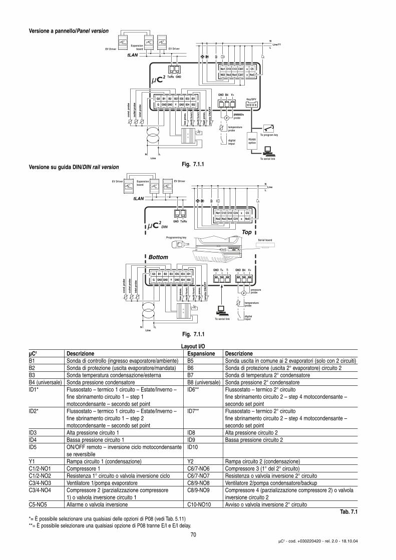
70µC2 - cod. +030220420 - rel. 2.0 - 18.10.04
G0 B1 B2 B3? ID5 ID3 ID1
G GND GND Y GND ID4 ID2
No1 C1/2 C1/2 C3/4? x C5
N02 No3 No4 C3/4? x No5
con
d. p
rob
e
ou
tlet
pro
be
inle
t p
rob
e
low
pre
ss.
mu
lti f
un
ct.?
mu
lti f
un
ct.?
hig
h p
ress
.
rem
ote
ON
/OF
F
Line??L
N
To program key
To serial link
RS485option
EV driver ESP
tLAN
Tx/Rx GND
GND B4 V+
P??????pressureprobe
temperatureprobe
digitalimput
Key/SPV
Line
LN
EV Driver EV DriverExpansion
board
EV driver
Fig. 7.1.1
G0 B1 B2 B3 ID5 ID3 ID1
G GND GND Y GND ID4 ID2
con
d. p
rob
e
ou
tlet
pro
be
inle
t p
rob
e
low
pre
ss.
mu
lti f
un
ct.
mu
lti f
un
ct.
hig
h p
ress
.
rem
ote
ON
/OF
F
GND B4 V+GND T+ T-
Ppressureprobe
temperatureprobe
digitalinput
LineLN
No1 C1/2 C1/2 C3/4 x C5
No2 No3 No4 C3/4 x No5
LineL
NExpansionboard
EV Driver
tLAN
Tx/RxGND
Top
Bottom
To serial link
Serial boardProgramming key
EV Driver
EV driver ESP EV driver
DIN
Fig. 7.1.1
Layout I/OµC2 Descrizione Espansione DescrizioneB1 Sonda di controllo (ingresso evaporatore/ambiente) B5 Sonda uscita in comune ai 2 evaporatori (solo con 2 circuiti)B2 Sonda di protezione (uscita evaporatore/mandata) B6 Sonda di protezione (uscita 2° evaporatore) circuito 2B3 Sonda temperatura condensazione/esterna B7 Sonda di temperatura 2° condensatoreB4 (universale) Sonda pressione condensatore B8 (universale) Sonda pressione 2° condensatoreID1* Flussostato – termico 1 circuito – Estate/Inverno – ID6** Flussostato – termico 2° circuito
fine sbrinamento circuito 1 – step 1 fine sbrinamento circuito 2 – step 4 motocondensante –motocondensante – secondo set point secondo set point
ID2* Flussostato – termico 1 circuito – Estate/Inverno – ID7** Flussostato – termico 2° circuitofine sbrinamento circuito 1 – step 2 fine sbrinamento circuito 2 – step 4 motocondensante –motocondensante – secondo set point secondo set point
ID3 Alta pressione circuito 1 ID8 Alta pressione circuito 2ID4 Bassa pressione circuito 1 ID9 Bassa pressione circuito 2ID5 ON/OFF remoto – inversione ciclo motocondensante ID10
se reversibileY1 Rampa circuito 1 (condensazione) Y2 Rampa circuito 2 (condensazione)C1/2-NO1 Compressore 1 C6/7-NO6 Compressore 3 (1° del 2° circuito)C1/2-NO2 Resistenza 1° circuito o valvola inversione ciclo C6/7-NO7 Resistenza o valvola inversione 2° circuitoC3/4-NO3 Ventilatore 1/pompa evaporatore C8/9-NO8 Ventilatore 2/pompa condensatore/backupC3/4-NO4 Compressore 2 (parzializzazione compressore C8/9-NO9 Compressore 4 (parzializzazione compressore 2) o valvola
1) o valvola inversione circuito 1 inversione circuito 2C5-NO5 Allarme o valvola inversione C10-NO10 Avviso o valvola inversione 2° circuito
Tab. 7.1*= È possibile selezionare una qualsiasi delle opzioni di P08 (vedi Tab. 5.11)**= È possibile selezionare una qualsiasi opzione di P08 tranne E/I e E/I delay.
Versione a pannello/Panel version
Versione su guida DIN/DIN rail version
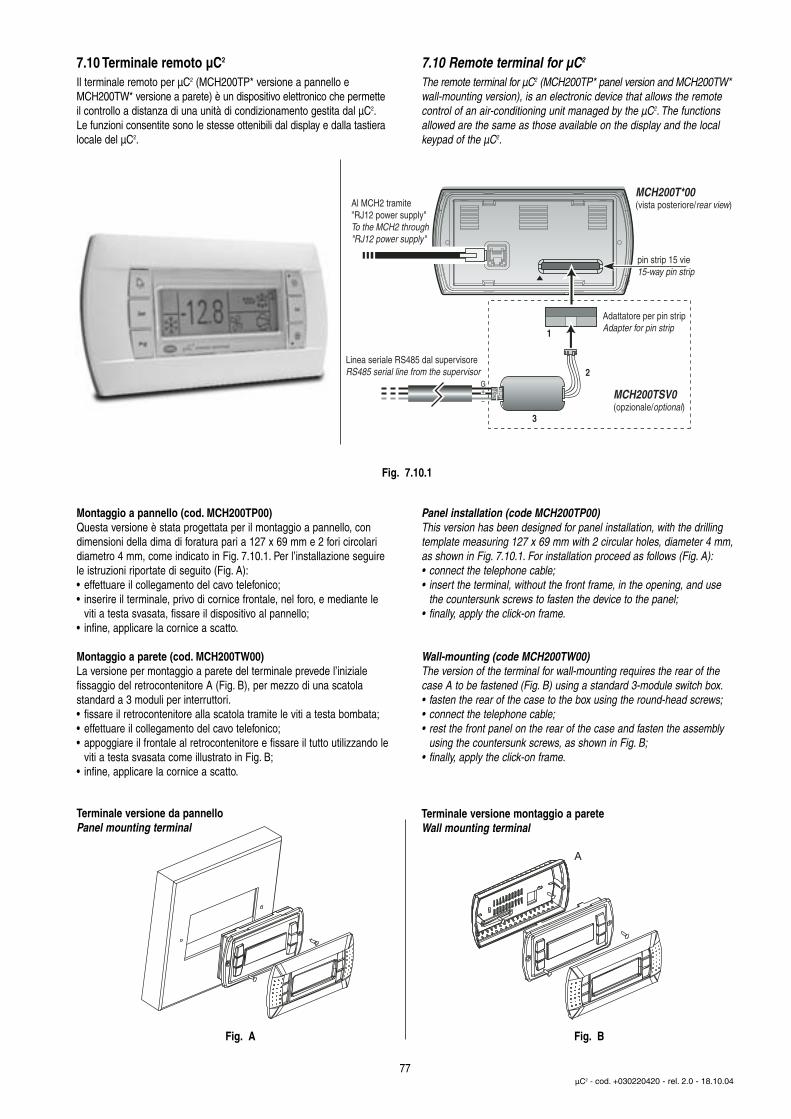
7.10 Terminale remoto µC2
Il terminale remoto per µC2 (MCH200TP* versione a pannello eMCH200TW* versione a parete) è un dispositivo elettronico che permetteil controllo a distanza di una unità di condizionamento gestita dal µC2.Le funzioni consentite sono le stesse ottenibili dal display e dalla tastieralocale del µC2.
Montaggio a pannello (cod. MCH200TP00)Questa versione è stata progettata per il montaggio a pannello, condimensioni della dima di foratura pari a 127 x 69 mm e 2 fori circolaridiametro 4 mm, come indicato in Fig. 7.10.1. Per l’installazione seguirele istruzioni riportate di seguito (Fig. A):• effettuare il collegamento del cavo telefonico;• inserire il terminale, privo di cornice frontale, nel foro, e mediante le
viti a testa svasata, fissare il dispositivo al pannello;• infine, applicare la cornice a scatto.
Montaggio a parete (cod. MCH200TW00)La versione per montaggio a parete del terminale prevede l’iniziale fissaggio del retrocontenitore A (Fig. B), per mezzo di una scatola standard a 3 moduli per interruttori.• fissare il retrocontenitore alla scatola tramite le viti a testa bombata;• effettuare il collegamento del cavo telefonico;• appoggiare il frontale al retrocontenitore e fissare il tutto utilizzando le
viti a testa svasata come illustrato in Fig. B;• infine, applicare la cornice a scatto.
7.10 Remote terminal for µC2
The remote terminal for µC2 (MCH200TP* panel version and MCH200TW*wall-mounting version), is an electronic device that allows the remotecontrol of an air-conditioning unit managed by the µC2. The functionsallowed are the same as those available on the display and the localkeypad of the µC2.
Panel installation (code MCH200TP00)This version has been designed for panel installation, with the drillingtemplate measuring 127 x 69 mm with 2 circular holes, diameter 4 mm,as shown in Fig. 7.10.1. For installation proceed as follows (Fig. A):• connect the telephone cable;• insert the terminal, without the front frame, in the opening, and use
the countersunk screws to fasten the device to the panel;• finally, apply the click-on frame.
Wall-mounting (code MCH200TW00)The version of the terminal for wall-mounting requires the rear of thecase A to be fastened (Fig. B) using a standard 3-module switch box.• fasten the rear of the case to the box using the round-head screws;• connect the telephone cable;• rest the front panel on the rear of the case and fasten the assembly
using the countersunk screws, as shown in Fig. B;• finally, apply the click-on frame.
77µC2 - cod. +030220420 - rel. 2.0 - 18.10.04
MCH200T*00
(vista posteriore/rear view)
Adattatore per pin stripAdapter for pin strip
pin strip 15 vie15-way pin strip
Al MCH2 tramite"RJ12 power supply"To the MCH2 through "RJ12 power supply"
1
2
3
MCH200TSV0(opzionale/optional)
Linea seriale RS485 dal supervisoreRS485 serial line from the supervisor
Fig. 7.10.1
A
Fig. A Fig. B
Terminale versione da pannelloPanel mounting terminal
Terminale versione montaggio a pareteWall mounting terminal

Collegamenti elettrici (Fig. 7.10.2-7.10.3)Collegare la linea seriale RS485 in uscita dall’alimentatore “RJ12Power supply” all’ingresso supervisore del µC2, utilizzando un cavoschermato ad una coppia intrecciata. Alimentare i morsetti G-G0 con untrasformatore e un fusibile da 250 mAT, come riportato nello schema di Fig.7.10.2 e 7.10.3. Effettuare il collegamento tra l’alimentatore “RJ12 Powersupply” e il terminale utilizzando il cavo telefonico (cod. S90CONN002 l = 80 cm) in dotazione. Nel caso la lunghezza sia insufficiente realizzareun cavo telefonico pin-to-pin di lunghezza massima pari a 40 m.Avvertenze:• utilizzare esclusivamente un trasformatore di sicurezza;• ai fini della sicurezza è obbligatorio inserire in serie al terminale ‘G’
un fusibile da 250 mA ritardato;• se si utilizza un trasformatore unico per µC2 e terminale rispettare la
polarità G-G0 come da schema elettrico. L’inversione equivale ad un cortocircuito sul secondario del trasformatore;
• non collegare a terra il secondario del trasformatore.
Linea alimentazione 24 Vac (G- G0)Distanze tipiche Sezione minima 250 m 1,5 mm2 (AWG16)100 m 0,5 mm2 (AWG20)50 m 0,35 mm2 (AWG22)
Tab.7.10.1
Linea seriale RS485 verso µC2
Velocità 19200 BaudDistanza massima RS485 1 Km (con terminazione da 120 ohm)Caratteristiche cavo una coppia intrecciata + schermoSezione AWG22Capacità per metro <90pF/m (ad esempio cavi
BELDEN 8761-8762)Tab.7.10.2
Electrical connections (Fig. 7.10.2-7.10.3)Connect the RS485 serial line leaving the power supply “RJ12 Powersupply” to the supervisor input on the µC2, using a twisted pair cablewith shield. Power terminals G-G0 from a transformer with a 250 mATfuse, as shown in the diagram in Fig. 7.10.2-7.10.3. Make the connection between the power supply “RJ12 Power supply” and the terminal using the telephone cable (code S90CONN002 l = 80 cm)supplied. If the cable is not long enough, use a pin-to-pin telephonecable with a maximum length of 40 m.Warnings:• only use safety transformers;• for safety reasons a 250 mA slow-blow fuse must be fitted in series
with terminal ‘G’;• if using the same transformer for the µC2 and the terminal, respect
the polarity G-G0 as per the wiring diagram. Reversing the polarity is the same as short-circuiting the secondary of the transformer;
• do not earth the secondary of the transformer.
24 Vac power supply line (G- G0)Typical length Minimum cross-section250 m 1.5 mm2 (AWG16)100 m 0.5 mm2 (AWG20)50 m 0.35 mm2 (AWG22)
Tab.7.10.1
RS485 serial line to µC2
Speed 19200 BaudMaximum RS485 distance 1 km (with 120 ohm terminals)Cable characteristics twisted pair + shieldCross-section AWG22Capacitance per metre < 90 pF/m (for example, BELDEN
8761-8762 cables)Tab.7.10.2
78µC2 - cod. +030220420 - rel. 2.0 - 18.10.04
in alternativaalternative:MCH200001*+FCSER00000(vedi Fig. 7.10.3)(see Fig. 7.10.3)
L. max.= 1000 m
RS485 doppino ritorto schermatoRS485 twisted pair + shieldRx/Tx+, Rx/Tx-, Gnd
L. max.= 40 mMax. l.= 40 m
RJ12 Power supply
Cavo telefonicoTelephone cable
N F
G0
24 Vac 3 VAclass 2 transformer
GFusibile 250 mAFuse
MCH200000* + MCH2004850MCH200TW*MCH200TP*
RJ12 – P
ow
er sup
ply
RS
48524 V
ac
GG0
–+
GN
D
Inserire resistenza di terminazione da 120 ohm tra Tx/Rx+ e Tx/Rx-, per linee di lunghezza superiori a 20 mInsert 120 ohm terminal resistor betweenTx/Rx+ and Tx/Rx- for lines longer than 20 m
1
2
3
Fig. 7.10.2
Schema di collegamento (alimentazione locale)/Connection diagram (local power supply)

InstallazionePer rendere operativo il terminale remoto nonè necessario effettuare alcuna configurazionedel µC2 in quanto il terminale funziona qualsiasi sia l’indirizzo seriale impostato tramite il parametro H10. Assicurarsi peròche il µC2 sia dotato di interfaccia serialeFCSER00000 (per versione guida DIN)oppure MCH2004850 (per versione a pannello). Alla prima accensione compariràsul display la versione firmware del µC2 (Fig. 7.10.4).
Dopo circa 4 s verrà visualizzata lamaschera principale con i simboli che rappresentano lo stato del µC2 (Fig. 7.10.5).
Nel caso il collegamento RS485 non siarealizzato correttamente oppure il controlloresia spento, il terminale cancellerà il contenuto del display e visualizzerà la scritta “OFFLINE” (Fig. 7.10.6).
Modo InfoLe pressione contemporanea dei tasti “Up” +“Down” + “Sel” per più di 6 s, forza la visualizzazione della maschera “INFO” (Fig.7.10.7) contenente informazioni sul sistemaµC2 e sulla comunicazione.Tramite la pressione del tasto “Prg” è possibile tornare alla maschera principale.
InstallationTo install the remote terminal, no configuration is required on the µC2, as theterminal works with any serial address setfor parameter H10. Check, however, thatthe µC2 is fitted with the serial interfaceFCSER00000 (DIN rail version) orMCH2004850 (panel version). When firstswitched on the display will show thefirmware version of the µC2 (Fig. 7.10.4).
After around 4 s the main screen will bedisplayed, with the symbols that representthe status of the µC2 (Fig. 7.10.5).
In the event where the RS485 connectionis not performed correctly or the controlleris off, the terminal will clear the display andshow the message “OFFLINE” (Fig. 7.10.6).
Info modePressing the “Up” + “Down” + “Sel” buttonstogether for more than 6 seconds displaysthe “INFO” screen (Fig. 7.10.7) containinginformation on the µC2 system and on thecommunication.Pressing the “Prg” button returns to themain screen.
79µC2 - cod. +030220420 - rel. 2.0 - 18.10.04
in alternativaalternative:MCH200000*+MCH2004850(vedi Fig. 7.10.2)(see Fig. 7.10.2)
L. max. = 250 m (sez. min. 1,5 mm2/AWG16)Max. l. = 250 m (min. cross-sect. 1.5 mm2/AWG16)
GG0
N F
24 Vac 15 VAclass 2 transformer
G0 G
MCH200TW*MCH200TP*
MCH200001* + FCSER00000
RJ12 – P
ow
er sup
ply
RS
48524 V
ac
GG0
–+
GN
D
Fusibile 250 mA Fuse
RJ12 Power supply
RS485 doppino ritorto schermatoRS485 twisted pair + shieldRx/Tx+, Rx/Tx-, Gnd
L. max.= 40 mMax. l.= 40 m
Cavo telefonicoTelephone cable
Inserire resistenza di terminazione da 120 ohm tra Tx/Rx+ e Tx/Rx-, per linee di lunghezza superiori a 20 mInsert 120 ohm terminal resistor between Tx/Rx+ and Tx/Rx- for lines longer than 20 m
1
2
3
Fig. 7.10.3
Fig. 7.10.5
Fig. 7.10.4
Fig. 7.10.6
Schema di collegamento (alimentazione remotata)/Connection diagram (remote power supply)
Fig. 7.10.7

Informazioni visualizzate (Fig 7.10.7):
Riga display Significato1 Versione firmware terminale2 Versione firmware µC2
3 Indirizzo supervisore del µC2
4 Tasso di errore percentuale relativo alla comunicaz. tra term. e µC2
Tab 7.10.3
Nel caso sia collegata la linea RS485 del supervisore tramite l’adattatoreMCH200TSV0 ed il supervisore sia attivo, appare in alto a destra l’icona“ ”; i due pallini a destra delle scritte Rx, Tx indicano rispettivamentei messaggi di richiesta inviati dal supervisore al µC2 di indirizzo H10 (Rx)e le trasmissioni di risposta da parte del µC2 (Tx): pallino vuoto = nessunatrasmissione (dati invariati), pallino pieno = dati trasmessi.
Collegamento alla rete di supervisione (MCH200TSV0)Qualora si desideri collegare il µC2 al terminale remoto MC2000TX00 senzaperdere la connettibilità alla rete di supervisione, è necessario installarel’adattatore seriale (opzionale) MCH200TSV0, come indicato in Fig.7.10.1.
Disconnettere il connettore telefonico, aprire la finestrella che copre ilpin-strip a 15 vie, utilizzando un tronchese appuntito, inserire l’adattatoreda pin-strip a plug 4 vie, rispettando il verso indicato in Fig 7.10.1 (pin1 a sinistra dal lato del triangolo). Eseguire il collegamento della reteRS485 al convertitore ed impostare il parametro H10 (indirizzo seriale)del µC2 al valore desiderato.
Information displayed (Fig 7.10.7):
Display row Meaning1 Terminal firmware version2 µC2 firmware version3 Supervisor address of the µC2
4 Percentage error rate in the communic. between the term. and µC2
Tab 7.10.3
If the RS485 supervisor line is connected via the MCH200TSV0 adapterand the supervisor is active, the “ ” icon is displayed at the topright; the two circles to the right of the Rx, Tx fields indicate respectively the request messages sent by the supervisor to the µC2
with address H10 (Rx) and the response from the µC2 (Tx): empty circle = no data sent (data unchanged), full circle = data sent.
Connection to the supervisor network (MCH200TSV0)To connect the µC2 to the remote terminal MC2000TX00 while stillmaintaining the possibility to connect to the supervisor network, the serialadapter (optional) MCH200TSV0 must be used, as shown in Fig. 7.10.1.
Disconnect the telephone connector, open the cover on the 15-way pinstrip using a small pair of wire cutters, and insert the adapter (pin-stripto 4-pin plug), in the direction shown in Fig 7.10.1 (pin 1 on the leftfrom the side of the triangle). Connect the RS485 network to the converter and set the parameter H10 (serial address) of the µC2 to thedesired value.
80µC2 - cod. +030220420 - rel. 2.0 - 18.10.04
Simbolo Significato Circuito frigoriferoAcceso Lampeggiante interessato
Symbol Meaning Refrigerant circuit ON Flashing involved
1,2 Compressore 1 e/o 2 acceso/Compressor 1 and/or 2 ON Richiesta di accensione/Start request 13,4 Compressore 3 e/o 4 acceso/Compressor 3 and/or 4 ON Richiesta di accensione/Start request 2
Almeno un compressore acceso 1 e/o 2At least one compressor ON 1 and/or 2Pompa/ventilatore aria mandata accesa/o Richiesta di accensione 1 e/o 2Pump/air outlet fan ON Start request 1 and/or 2Ventilatore di condensazione attivato 1 e/o 2Condenser fan ON 1 and/or 2Sbrinamento attivo Richiesta di sbrinamento 1 e/o 2Defrost active Defrost request 1 and/or 2Resistenza attivata/Heater ON Richiesta di accensione/Start request 1 e/o 2/1 and/or 2
Tasto alarm LED rosso Allarme attivo 1 e/o 2Alarm button Red LED Alarm active 1 and/or 2
Allarme attivo Allarme EEPROM 1 e/o 2Alarm active EEPROM alarm 1 and/or 2Relè avviso attivato (solo con scheda espansione)Warning relay activated (only with expansion board)Relè allarme attivatoAlarm relay activatedModalità Pompa di Calore (P6=0) Richiesta cambio di stagione 1 e 2Heat pump mode (P6=0) Season changeover request 1 and 2Modalità Refrigeratore (P6=0) Richiesta cambio di stagione 1 e 2Chiller mode (P6=0) Season changeover request 1 and 2
Tab.7.10.4
Fig. 7.10.7
Interfaccia utente/User interface
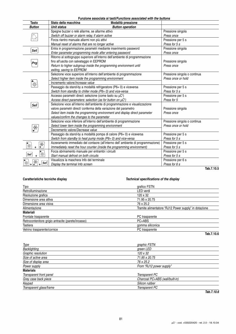
Caratteristiche tecniche display Technical specifications of the display
81µC2 - cod. +030220420 - rel. 2.0 - 18.10.04
Funzione associata ai tasti/Functions associated with the buttonsTasto Stato della macchina Modalità pressione
Button Unit status Button operationSpegne buzzer o relè allarme, se allarme attivo Pressione singolaSwitch off buzzer or alarm relay, if alarm active Press onceForza rientro manuale allarmi non più attivi Pressione per 5 sManual reset of alarms that are no longer active Press for 5 sEntra in programmazione parametri mediante inserimento password Pressione singolaEnter parameter programming mode after entering password Press onceRitorno al sottogruppo superiore all’interno dell’ambiente di programmazionefino all’uscita con salvataggio in EEPROM Pressione singolaReturn to higher subgroup inside the programming environment until Press onceexiting, saving to EEPROMSelezione voce superiore all’interno dell’ambiente di programmazione Pressione singola o continuaSelect higher item inside the programming environment Press once or holdIncremento valore/Increase valuePassaggio da stand-by a modalità refrigeratore (P6= 0) e viceversa Pressione per 5 sSwitch from standby to chiller mode (P6= 0) and vice-versa Press for 5 sAccesso parametri direct: selezione (come tasto su µC2) Pressione per 5 sAccess direct parameters: selection (as for button on µC2) Press for 5 Selezione voce all’interno dell’ambiente di programmazione e visualizzazionevalore parametri direct/ conferma della variazione del parametro Pressione singolaSelect item inside the programming environment and display direct parameter Press oncevalues/confirm the changes to the parameterSelezione voce inferiore all’interno dell’ambiente di programmazione Pressione singola o continuaSelect lower item inside the programming environment Press once or holdDecremento valore/Decrease valuePassaggio da stand-by a modalità pompa di calore (P6= 0) e viceversa Pressione per 5 sSwitch from standby to heat pump mode (P6= 0) and vice-versa Press for 5 sAzzeramento immediato del contaore (all’interno dell’ ambiente di programmazione) Pressione per 5 s
+ Immediately reset the hour counter (inside the programming environment) Press for 5 sForza sbrinamento manuale per entrambi i circuiti Pressione per 5 s
+ Start manual defrost on both circuits Press for 5 sVisualizza la maschera Info del terminale Pressione per 6 s
+ + Display the terminal Info screen Press for 6 sTab.7.10.5
Tipo grafico FSTNRetroilluminazione LED verdiRisoluzione grafica 120 x 32Dimensione area attiva 71.95 x 20.75Dimensione area visiva 76 x 25.2Alimentazione Tramite alimentatore “RJ12 Power supply” in dotazioneMaterialiFrontale trasparente PC trasparenteRetrocontenitore grigio antracite (parete/incasso) PC+ABS Tastiera gomma siliconicaVetrino trasparente/cornice PC trasparente
Tab.7.10.6
Type graphic FSTNBacklighting green LEDGraphic resolution 120 x 32Size of active area 71.95 x 20.75Size of display area 76 x 25.2Power supply From “RJ12 power supply”MaterialsTransparent front panel Transparent PCGrey case back piece Charcoal PC+ABS (wall/built-in)Keypad Silicon rubberTransparent glass/frame Transparent PC
Tab.7.10.6