Embed Size (px)
Citation preview

AD-A205 452AFWAL-TR-88-2045
LONG PULSE HOMOPOLAR GENERATOR
Edward A. Knoth
David P. Bauer
lAP Research, Inc.
2763 Culver Avenue
Dayton OH 45429-3723
August 1988
Final Report for Period April 1983 - June 1987
Approved for public release; distribution is unlimited
DTICAEROPROPULSION LABORATORY ELECTEAIR FORCE WRIGHT AERONAUTICAL LABORATORIES M'. 2O09l
AIR FORCE SYSTEM COMMAND
WRIGHT-PATTERSON AIR FORCE BASE, OHIO 45433-6563 D
8en2

UnclassifiedSECURITY CLASSIFICATION OF THIS PAGE
' Frm ApprovedREPORT DOCUMENTATION PAGE OuBN.o0o0o18
l. REPORT SECURITY CLASSIFICATION lb. RESTRICTIVE MARKINGS
jnelaRsif Ied _2a. SECURITY CLASSIFICATION AUTHORITY 3. DISTRIBUTION IAVAILABILITY OF REPORT
Approved for public release2b. DECLASSIFICATIONIDOWNGRADING SCHEDULE distribution is unlimited
4. PERFORMING ORGANIZATION REPORT NUMBER(S) S. MONITORING ORGANIZATION REPORT NUMBER(S)
AFWAL-TR-88-2045
6a. NAME OF PERFORMING ORGANIZATION 6b. OFFICE SYMBOL 7o. NAME OF MONITORING ORGANIZATIONlAP Research, Inc. (if appikable) Air Force Wright Aeronautical Laboratories
I _Aero Propulsion Laboratory (AFWAL/POOC-4)6c. ADDRESS (City, Statt, and ZIP Code) 7b. ADDRESS (City, State. and ZIP Code)
2763 Culver Avenue Wright-Patterson AFB, OH 45433-6563Dayton, OH 45429-3723 W
Sa. NAME OF FUNDING/SPONSORING 1b. OFFICE SYMBOL 9. PROCUREMENT INSTRUMENT IDENTIFICATION NUMBERORGANIZATION (If appikable)j F33615-83-C-2303
8c. ADDRESS (City, State, and ZIP Code) 10. SOURCE OF FUNDING NUMBERSPROGRAM PROJECT TASK WORK UNITELEMENT NO. NO. NO ACCESSION NO.
61101F ILIR P3 0111. TITLE (include Security Classiflcation)
Long Pulse Homopolar Generator
12. PERSONAL AUTHOR(S)David P. Bauer Edward A. Knoth
13s. TYPE OF REPORT 13b. TIME COVERED 14. DATE OF REPORT (Year, Month, Day) 15. PAGE COUNTFinal FROMAPr 83 TO Jun 87 August 1988 30
16. SUPPLEMENTARY NOTATION
17. COSATI CODES IS. SUBJECT TERMS (Continue on revoere if neceuwy and identify by block number)FIELD GROUP SUB-GROUP C6 6; y .- o- , -, ', -
20 07 homopolar, high current, high power, high speed, generator,
19. ABIT!CT (Contkwe on rer if =ray and )ntI y by block number)
The objective of this program was to develop a lightweight, long pulse
homopolar generator. The generator is'\designed to deliver 250 kW at 10 kA for
pulses greater than 10 seconds.
This report reviews the truncated drui (rotor) design and the testingperformed. The main design features, such)as active excitation coil cooling,
of the generator components are reviewed.I
20. DISTRIBUTION I AVAILABILITY OF ABSTRACT 21. fBSTsA REgyRY CLASSIFICATIONG UNCLASSIFIEDIUNUMITED C3 SAME AS RPT. Q3 DTIC USERS nc Z jfe
22a. NAME OF RESPONSIBLE INDIVIDUAL 22b. TELEPHONE "nd Code) 22€. OFFICE iYMBOLJohn Horwath (513) 255-919 AFWAL/ POOC-4
DO Form 1473, JUN 6 Previused ofvo obolete. SE t)JRITYCLASSIFICATION OF THIS PAGEUnclassifiled
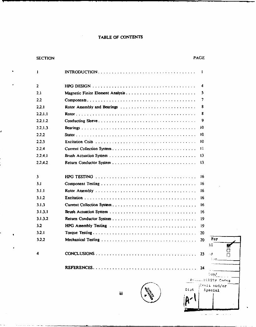
TABLE OF CONTENTS
SECTION PAGE
I INTRODUCTION ................................... I
2 HPG DESIGN ..................................... 4
2.1 Magnetic Finite Element Analysis ......................... 5
2.2 Components ....................................... 7
2.2.1 Rotor Assembly and Bearings ........................... 8
22.1.1 Rotor ........................................... 8
2.2.1.2 Conducting Sleeve ................................... 9
2.2.1.3 Bearings ......................................... 10
2.2.2 Stator ..... ... ...... ... .......................... 10
2.2.3 Excitation Coils .................................... 10
2.2.4 Current Collection System ................................ II
2.2.4.1 Brush Actuation System ............................... 13
22.4.2 Return Conductor System ................................ 13
3 HPG TESTING .................................... 16
3.1 Component Testing .................................. 16
3.1.1 Rotor Assem bly .................................... 16
3.1.2 Excitation ........................................ 16
3.1.3 Current Collection System ................................ 16
3.1.3.1 Brush Actuation System ............................... 16
3.1.3.2 Return Conductor System ................................ 19
3.2 HPG Assembly Testing ............................... 19
3.2.1 Torque Testing ..................................... 20
3.2.2 Mechanical Testing .................................. 20 For
4 CONCLUSIONS ...................................... 23 c' []
REFERENCES....................................... 24
A'. Jity/Av,- , .-il t.v 0
N 2 v~j i d/or' ulit Sp ecil
iii VI - 1L

LIST OF FIGURES
FIGURE PAGE
I Pulse power system for "long pulses" ....................... I
2 Our long pulse HPG ................................. 2
3 The homopolar generator .............................. 4
4 HPG flux distribution ................................ 6
5 Magnetic flux density in current collection region ............... 7
6 HPG rotor assembly ................................. 8
7 Excitation current requirements limit sleeve thickness ............. 9
8 HPG stator (housing) ................................... 11
9 Generator voltage is dependent on excitation current ............. 12
10 Water is used to cool the excitation coils ....................... 12
11 HPG electrical circuit .. ................................ 13
12 HPG brush actuation system .............................. 14
13 HPG stator linings ................................... 15
14 Rotor assembly in test fixture . .......................... 1715 Supply pressure of 550 kPa is required ........................ 17
16 Brush load is linear with supply pressure ...................... 18
17 Air flow rate is dependent on supply pressure .................. 18
18 Stator linings will remain cool during testing ................... 19
19 Brush frictions increase with supply pressure ................... 20
20 HPG rotor before and after testing ......................... 22
iv

LUST OF TABLES
TABLE PAGE
I HPG Specifications...................................... 5
2 Temperature Data....................................... 21

SECTION 1
INTRODUCTION
Air Force pulse power applications continue to increase in number. Pulse power
applications require very high levels of power (typically megawatts) in relatively long pulses
(a few seconds to several minutes). A repetitive electromagnetic gun is an example of this
type of application. Average power on the order of 40 MW is required.1 Energy storage
systems sized to meet this requirement would be impractically large. We proposed an alter-
native concept involving a non-air-breathing turbine and a "long pulse" homopolar generator(HPG).2
The long pulse power system concept is illustrated in Figure 1. As configured for an
electric gun system, it would consist of a non-air-breathing turbine, high current homopolar
generator, an energy storage coil, and a repetitive switch. The turbine and generator pro-
duce the required high current and high average power, while the energy storage coil and
switch compress the energy further to provide repetitive, high current pulses at power levels
2 to 3 orders of magnitude above the average power level. This system has very attractive
characteristics for many pulse power applications involving either very long pulses or bursts
of pulses lasting for seconds or more.
GAS GENERATORFUEL
ENERGY STORAGE COIL
PROJECTILE LOADER
-...-----, BARREL
~SW/ITCH
GENERATOR
TURBINE (195)
Figure 1. Pulse power system for "long pulses".
=-- -- I

The major components of this power system concept are at varying stages of develop-
ment. The Air Force is continuing the development of high power turbines, inductive
energy storage, and opening switches to meet the high power, long pulse requirements. This
report describes the characteristics of a scaled homopolar generator designed to operate with
the other components of a long pulse, high current power system. This program was the
first effort by the Air Force to design and build such a generator.
Most high current homopolar generators built to date are energy storage devices.
Energy is stored rotationally and delivered in a single, high current pulse to a load. Dis-
charge times for these machines are less than I second.
The objective of this program was to develop a lightweight, long pulse homopolar
generator. The generator, shown in Figure 2, was designed to deliver 250 kW at 10 kA for
a pulse length of 5 seconds.
Figure 2. Our long pulse HPG.
The program began with the evaluation of alternate geometries for generator construc-tion. Single, double, and tapered disk and several shell rotor configurations were considered.
This report focuses on the truncated drum HPG configuration which was built.
2

This report has three remaining sections. Section 2 describes the design of the HPGand its components. Section 3 reviews the component and HPG assembly testing. Section 4presents the conclusions.
I
SECTION 2
HPG DESIGN
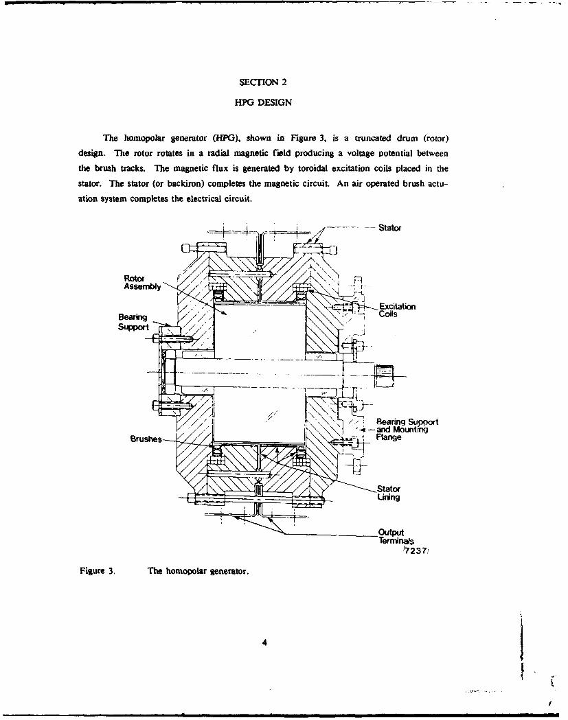
The homopolar generator (HPG), shown in Figure 3, is a truncated drum (rotor)
design. The rotor rotates in a radial magnetic field producing a voltage potential between
the brush tracks. The magnetic flux is generated by toroidal excitation coils placed in the
stator. The stator (or backiron) completes the magnetic circuit. An air operated brush actu-
ation system completes the electrical circuit.
Assembly " ..
-Excitation
BearingCoilsSupport r, _
/// Bearing Sujpfor t
Brushes. Flange
(7237
Figure 3. The homopolar generator.
4
I.i a l i i

Table I ists some of the HPG design specifications. The following subsections will
review the magnetic analysis performed and the main design features of the generator com-
ponents.
Table I
HPG Specifications
Parameter Value Units
Output Voltage 30 V
Output Current 10 kA
HPG Overall Size
Diameter 370 mm
Length 340 mm
Weight 190 kg
Excitation
Magnetic Flux Density 1.5 T
Current 820 A
Water Supply Pressure 550 kPa
Rotor
Rotational Speed 19,100 rpm
Diameter 200 nun
Length 132 mm
Weight (about) 40 kg
Brush Supply Pressure 275 kPa
2.1 Magnetic Finite Element Analysis
Magnetic Finite Element Analysis (MFEA) was performed in conjunction with HPG
component design. Magnetic analysis enabled u to analyze the effects of device geometry
and materials on the flux distribution. The leakage magnetic flux densities in the current
collection and rotor bearing areas were of particular interest in the HPG design.
5

Figure 4 indicates that some radial flux passes through the current collection brushes.
Figure 5 shows an expanded plot of the finite element model in the current collection
region. The magnitude and direction of the flux density in each element near the brush-
rotor interface is superimposed on Figure 5. The average radial component of magnetic flux
passing through the brush face is 0.159 T. The voltage gradient across the brush due to this
flux is given by:
V=B ()
where V' = the voltage gradient
B = the magnetic flux density, and
v - the sliding velocity at the interface.
i,/ r Bearing
-- . -oi S -.
FShft Rotor Stator (7239)
Figure 4. HPG flux distribution.
For a rotor tip speed of 200 m/s, the brush voltage is 31.9 V/r. According to work done
by Marshall4 , voltage gradients on brushes cause a nonuniform current distribution and
therefore nonuniform heating within the brushes. Based on experiments with copper-
graphite brushes operating at a current density of 6.5 MA/m 2 , an acceptable voltage gradient
on the brush face is 40 V/r. Therefore, the level of magnetic flux density in the brush
area is acceptable and will not cause excessive brush heating.
6

Stator-_ -- o-
tu . A1 -StatorB uhAre
1.5 LIS ______I
I-Rotor Excitation Coil (7232)
Figure 5. Magnetic flux density in current collection region.
Figure 4 indicates that the magnetic flux density in the bearing area is very low. The
results show that bearing flux density is about 0.008 T. The bearing functions like a drum
type HPG with the predominant voltage axial along the inner race. The voltage generated
can be calculated as:
Vb = Blvb, (2)
where Vb the bearing voltage,
I = the inner race thickness (0.015 m), and
vb the inner race surface speed (40 m/s).
The bearing generated voltage is about 5 mV. The upper limit of acceptable bearing voltage
has been established as 50 to 100 mV5 . Therefore, the level of magnetic flux density pre-
sent in the bearing location does not present a problem to bearing operation.
2.2 Components
The HPG consists of rotating and stationary components. The rotating components
include the rotor assembly and bearings. The stationary components consist of the stator,
excitation coils, and current collection system. The HPG's rotor assembly and bearings,
stator, excitation coils, and current collection system will be discussed in the following sub-
sections.
7
. . -

2.2.1 Rotor Assembly and Bearings
The rotor assembly, shown in Figure 6, can be divided into two parts: the rotor and
the conducting sleeve. Deep-groove ball bearings support the rotor. The rotor, conducting
sleeve, and bearings will be discussed in the following subsections.
Shaf t ShaftCollar
Brush-tracks
7240Figure 6. HPG rotor assembly.
2.2.1.1 Rotor
The rotor consists of four individual parts: the shaft, the core, and the two shaft col-
lars. A nonmagnetic shaft material, 303 stainless steel, was chosen to reduce the magnetic
flux density in the bearing locations. Power is transferred to the shaft through a standard
AN-4182 external spline. A 475 N-m shear section is located directly behind the input
spline to protect the drive system and torque transducer.
The rotor core is made from 4340 steel. A shrink fitting procedure was used to insert
the oversized shaft into the rotor core. The rotor was heatee to 1770 C in an oven while
the shaft was cooled to -1960 C by submerging it in liquid nitrogen (LN.). The interference
fit of 0.10 mm is sized to transmit the required torque at design conditions.
The two shaft collars were made from 1020 steel. The collars were pressed onto the
shaft (interference of 0.06 mm) until they contacted the rotor core. These collars stiffen the
shaft and place the natural frequency of the rotor assembly beyond the operating range.
8

2.2.1.2 Conducting Sleeve
The conducting sleeve is made from extruded 6061-T6 aluminum tube. The sleeve isinsulated from the rotor core by two layers of 56 im thick Kapton film. A shrink fittingprocedure is also used to slip the sleeve onto the rotor core. The sleeve to core interference
(including insulation) is 0.51 mm.
The outer surface of the sleeve contains two brush tracks, one at each end. Silverplating is used to prevent aluminum oxide from forming at the brush interface. The surfacebetween the brush tracks is hard anodized to prevent arcing from the sleeve surface to the
current collection system.
A sleeve thickness of 4.2 mm was chosen to keep the excitation power requirementsbelow 10,000 A-T. Figure 7 shows the flux density obtained from a specified level of exci-tation for several thicknesses of rotor conductor. Although the design level flux density is1.5 T, we selected 1.65 T as the flux density attainable at an excitation of 10,000 A-T to
allow for some margin in excitation performance.
I4e Design Flux Density1.6 Excitation Limit
(U . .............. --- -- 32 an Thick Conductor1" .4 . ' "1.4 42 us Thick Conductort.2
S5 usr Thick Conductor
9t.e
C 08 W EtS: (7241)0 .6 - 1 *.215 a 1018 Steeli 2 0.08 a 4340 Steel
X 0.4 3 0.02 e Air
=, .z
925 0 508 75 1089 1258 1 S M
Applied MMF (A-T )
Figure 7. Excitation current requirements limit sleeve thickness.
9

2.2.1.3 Bearings
Deep-groove ball bearings were selected because they can support radial and thrust
loads. Rotor weight determines the radial load. Thrust load is dependent on the rotor to
end stator air gaps and generator excitation. A peak thrust load of approximately 9 kN is
expected ,: maximum excitation.
We purchased two P/N 107FFT-G6 bearings from The Barden Corporation. The
selectd bearings are made from SAE 52100 bearing steel, prelubricated with
Exxon Andok C grease, and permanently sealed.
2.2.2 Stator
The stator (or housing) serves two purposes. First, the stator provides a low reluctance
path for the excitation magnetic flux. Second, the stator functions as the HPG's housing.
The stator provides location plus support for the excitation coils, current collection system,
and rotor assembly.
The stator is divided into four parts as shown in Figure 8. Most of the stator is made
from 1020 steel. The bearing and mounting inserts, located in the end stators, are made
from 303 stainless steel to keep the magnetic flux density low in the bearing locations.
2.2.3 Excitation Coils
The excitation coils provide the magnetic flux needed by the HPG to convert mechan-
ical energy into electrical energy. The coils are made from commercially available 3/16 inch
square copper tubing. The tubing was wrapped around a 118.8 mm radius cylinder forming
two layers- with 5 turns each.
The voltage created by the generator is dependent on the excitation current level.
Figure 9 shows how generator voltage increases with increasing excitation current. The
excitation current must be approximately 820 A to operate the generator at the design volt-
age of 30 V. Excitation current level is regulated by a 16 V, 1000 A DC power supply.
The heat generated by the excitation coils is removed by water passing through the
coils. Figure 10 shows the supply pressure needed to keep the water temperature rise below
600 C. The supply pressure required to drive the water through the coils at the design cur-
rent is 550 kPa.
10

(a) Center Stators
(b) End Stators
Figure 8. HPG stator (housing).
2.2.4 Current Collection System
The current collection system can be divided into two systems: brush actuation and
return conductor. The brush actuation system contacts silver-plated brush tracks at each end
of the conducting sleeve to complete the electrical circuit shown in Figure 11. The return
conductor system connects the brush actuation system to the ioad. The brush actuation and
return conductor systems will be discussed in the following subsections.
1.

S30
I254-"
,"-4
L 150 NOTES- (7214
-io
0 190 200 300 440 5o 600 700 e 9090 19e0
Excitation Current (A)
Figure 9. Generator voltage is dependent on excitation current.
0eC. 140 LEMl :
338 kPa
0 4SO kPaw 2 .......
I/ , 580 a
Cie.
440
~T40
- 0- 2-!00 60 "I
Current Level (A )
Figure 10. Water is used to cool the excitation coils.
12 I

Brush Actuation Syjstem
,+
HPG Rotor ' Load
Y r
L R e t u r n C o n d u c t o r S s t e m
(7210) Generator
Figure I1. HPG electrical circuit.
2.2.4.1 Brush Actuation System
The brush actuation system is shown in Figure 12. The brushes are I cm square
blocks of CMIS (copper-graphite) material. Each brush is 5.08 mm thick, radially. Brush
straps connect the brushes to the air supply manifold. The brush straps are made from 16
pieces of 12.7 mm x 76 pm (1/2 inch X 0.003 inch) thick copper foil soldered at each end.
Pistons are used to load the brushes onto the rotor surface. The pistons are located in the
air supply manifold. The manifold is made from 6.35 mm x 12.7 mm (1/4 inch X 1/2 inch)
rectangular copper tubing with 40 copper piston cylinders soldered to the inner diameter.
The brush straps were made from foil to decrease the strap stiffness and to increase
the current carrying cross-sectional area. After testing is complete, the brush straps function
as a weak spring to deactuate the brushes.
2.2A.2 Return Conductor System
Two pars form the return conductor system. They are the stator lining and the
output terminals. The C-shaped stator linings snap around the inner diameter of the center
stators. Screws fasten the brush actuation system to the linings. The L-shaped output ter-
minals connect the load cables to the stator linings.
13

i ~ ~Brush Strop •:,
Figure 12. HPG brush actuation system.
The stator linings are shown in Figure 13. They were made from 1.02 mm
(0.040 inch) copper sheet. The linings are adiabatically sized to keep their temperature rise
below 100 C during a current pulse. Varnish was used to electrically insulate and join the
linings and center stators.
14

....... ..... . ... . ..
Figure 13. HPG stator linings.
15

SECTION 3
HPG TESTING
3.1 Component Testing
Component testing was performed prior to HPG assembly. The tests performed on
the rotor assembly, excitation coils, and current collection system are discussed in the fol-
lowing subsections.
3.1.1 Rotor Assembly
The rotor assembly shown in Figure 14 was spin tested by The Balancing Com-
pany, Inc. The rotor was held at 19,000 rpm for 30 seconds (design condition). Then, the
rotor was held at 21,000 rpm for 60 seconds (design condition +10 percent). This testing
verified the mechanical integrity of the rotor assembly.
The rotor assembly passed a voltage standoff test. A 35 V potential was placed across
the sleeve-to-core insulation. This insulation prevents ground loops from passing current
through the bearings.
3.1.2 Excitation
The excitation coils were tested to verify coolant supply requirements. Figure 15
illustrates the relationship between excitation current level and water temperature rise for
various supply pressures. A water supply pressure of 550 kPa (80 psig) or greater is needed
to keep the water from boiling at the exit.
3.1.3 Current Collection System
The current collection system was tested prior to HPG assembly. The tests relating to
the brush actuation system and return conductor system will be discussed in the following
subsections.
3.1.3.1 Brush Actuation System
Load tests were conducted on the left and right brush actuation systems. Supply pres-
sure was varied from 275 to 410 kPa (25 to 45 psig). A load cell was used to measure indi-
vidual brush loads. The average brush load versus supply pressure is illustrated in
Figure 16.
16I

Figure 14. Rotor assembly in test fixture.
U0140 LEM1 :
N 330 kPaILI 129
450 kPa
to So I kP
'1B2 kPa
,4'w oe-'
' -,, .Y NOTES:
,1 26 - . 94-fL I-.. ..E
1-- 0 , I
0 260 460 6* go low
Current Level (A)
Figure 15. Supply pressure of 550 kPa is required.
17

% t LEGID:z . .
Test Data
S5 "Straight Line Fit
0
4
IA3 3L
02
L I
L9a 3W 35W 40 450 so
Supply Pressure (kPa)
Figure 16. Brush load is linear with supply pressure.
The air flow rate required to operate the brushes at a given supply pressure is shown
in Figure 17. An air supply pressure of 275 kPa (25 psig) is required at the design current
level of 10,000 A.
36 LE ED:* 0 *Test Data
0System Requirements
0) 3
3-o L- 24
NOTES:02)
L4M 18
12 I I
250 3W 350 4W 450 so
Supply Pressure (kPa)
I fgtie 17. Air flow rate is dependent on supply pressure.
18

3.1.3.2 Return Conductor System
Two tests were performed on the stator linings. One test measured the temperature
rise of the solder joints versus current and time. The other test verified that the linings
were insulated from the stator.
Figure 18 illustrates the relationship between stator lining joint temperature rise, cur-
rent, and operating time. A stator lining temperature rise of approximately 70 C can be
expected during peak current testing. Each lining will conduct 2500 A.
A Hewlett-Packard high resistance meter, Model 4329A, measured the resistance
between the stator linings and the stator. The resistance values ranged from 340 to
3500 MO. Therefore, the linings were effectively insulated from the stator.
Q. 39 LEGEND:
U U~1 second
'ID .. .
0Z 55- second*Is seconds
A A A1 secondsoPA
CheC
15
L A
- 10 NOTES: (7fl1)
L(U5
2JI. 1 2W 2250 25W 2750
Current (A)
Figure 18. Stator linings will remain cool during testing.
3.2 HPG Assembly Testing
HPG testing included torque and mechanical testing. Overspeed and thermal stresses
caused a rotor sleeve failure during the mechanical testing. This failure precluded final
brush friction, voltage, and current testing during this program. The following subsections
discuss the torque and mechanical tests performed on the HPG.
19
.

3.2.1 Torque Testing
Torque tests were performed on the HPG after assembly. The tests measured the
breakaway torque of the bearings and the coefficient of friction of the brushes. The
breakaway torque ranges from 0.68 to 0.90 N-m (6 to 8 in-lbf). Figure 19 shows the torque
required to overcome brush friction. The measured static coefficient of friction was 0.23.
12 LGM" IZ. w. . , . . .l]
Test Data
Straight Line Fit
L " BI
L0
6
i HOES:3'4
irL
250 300 350 400 450 5
Supply Pressure (kPa)Figure 19. Brush frictions increase with supply pressure.
3.2.2 Mechanical Testing
On June 8, 1987 mechanical testing was started. Five tests were to be performed.
The first four would take the generator to 20,000 rpm in 5,000 rpm increments. The fifth
test would take the generator to 21,010 rpm, a 10 percent overspeed condition.
Table 2 contains temperature data for the last three tests. TLkiR is the temperature of
one brush on the left brush actuation system. TLBRG and TRBRG represent the left and
right bearing temperatures, respectively. This data indicates the bearings were operating
satisfactorily before and after the generator sleeve failure. The temperatures listed are
steady-state values.
20
: : : -""m " I RI~l mnl B~l I

Table 2
Temperature Data
Test No. 3 4 5
Speed, rpm 14,228 20,371 21,198
TLBR, oC 65 80 37>468*
TLBRG, CC 29 30 28/35*
TRBRG, OC 24 26 28/119*
*Data shown is following generator failure.
In addition to temperatures, generator torque and vibration were measured. The
torque and vibration signals indicated that the generator was operating smoothly.
During the fifth test on June 10, 1987 the generator failed. The generator reached a
speed of 21,549 rpm before settling to 21,198 rpm. The generator was at speed for
approximately 4 seconds prior to a sudden torque increase. The increase in torque slowed
the rotor to 19,753 rpm. The motor was delivering maximum power.
The operator requested the motor to shut down at a rate of 2000 rpm/s. The motor
control did a good job regulating the deceleration considering what was going on inside the
generator. At 8,541 rpm the generator was brought to a stop in 0.280 second or
20 revolutions. This sudden stop was caused by friction welding of the input spline's rotor
collar to the right end plate.
After disassembling and examining the HPG, the following sequence of events was
formulated. The aluminum sleeve while subjected to a speed of 2220 rad/s continued to
expand due to frictional heating caused by dragging brushes. This expansion continued until
the sleeve contacted a stator lining. The large increase in brush temperature following the
torque excursion indicates that failure occurred near this location. This contact initiated the
torque excursion. The increase in power consumption was used to melt away a section of
the sleeve resulting in an unbalanced rotor. The rotor unbalance was responsible for
bending the shaft and friction welding the rotor collar to the end stator. Figure 20 shows a
before and after view of the rotor assembly.
21
I

Figure 20. HPG rotor before and after testing.
22

SECTION 4
CONCLUSIONS
The HPG is designed to deliver 250 kW at 10 kA for a pulse length greater than
10 seconds. We are rebuilding this generator for future government testing.
The generator developed by this program has a compact design which is scalable to
larger machines. Many of the features required for continuous operation are present. These
features include water cooled excitation coils and air cooled brushes.
The test plan for this program was flawed. The generator was placed at high risk
before most of the performance data was obtained. Future test plans will be sequenced to
perform high risk tests at the end of a test program.
U
23*U.S.Oovwnment Pr|nting Officet 1989 - 646-056/04191