Embed Size (px)
Citation preview

Siemens DA 51.2 · 2007/2008 2/1
2
InverterMICROMASTER 420
2/2 Description
2/4 Circuit diagrams
2/6 Technical data
2/8 Selection and ordering data
2/9 Options
2/18 Dimension drawings
© Siemens AG 2007

2/2 Siemens DA 51.2 · 2007/2008
MICROMASTER 420
2
Application Main characteristics Options (overview) International standards
The MICROMASTER 420 in-verter is suitable for a variety of variable-speed drive appli-cations. It is especially suit-able for applications with pumps, fans and in conveyor systems.
It is the ideal cost-optimized frequency inverter solution. The inverter is especially char-acterized by its customer-ori-ented performance and ease-of-use. Its large mains voltage range enables it to be used all over the world.
Design
The MICROMASTER 420 in-verter has a modular design. The operator panels and com-munication modules can be easily exchanged without re-quiring any tools.
Easy, guided start-up Modular construction al-
lows maximum configura-tion flexibility
Three fully programmable isolated digital inputs
One analog input (0 V to 10 V, scaleable) or for use as 4th digital input
One programmable analog output (0 mA to 20 mA)
One programmable relay output (30 V DC/5 A resis-tive load; 250 V AC/2A in-ductive load)
Low-noise motor operation through high pulse frequen-cy, adjustable (observe de-rating if necessary)
Complete protection for motor and inverter.
EMC filter, Class A/B LC filter Line commutating chokes Output chokes Gland plates Basic Operator Panel
(BOP) for parameterizing the inverter
Advanced Operator Panel (AOP) with multi-language plain text display
Asian Advanced Operator Panel (AAOP) with Chinese and English plain text dis-play
Cyrillic Advanced Operator Panel (CAOP) with Cyrillic, German and English plain text display
Communication modules– PROFIBUS– DeviceNet– CANopen
PC connection kits Mounting kits for installing
the operator panels in the control cabinet doors
PC start-up programs exe-cutable under Windows 98 and NT/2000/ME/XP Professional
TIA integration with Drive ES
The MICROMASTER 420 inverter complies with the requirements of the EU low-voltage guideline
The MICROMASTER 420 inverter has the > mark-ing
acc. to u and cu certified c-tick
Note:
See Appendix for standards.
Description
© Siemens AG 2007

Siemens DA 51.2 · 2007/2008 2/3
MICROMASTER 420
2
Mechanical features Performance features Protection features
Modular design Operating temperature
–10 °C to +50 °C (+14 °F to +122 °F)
Compact housing as a re-sult of high power density
Easy cable connection, mains and motor connec-tions are separated for opti-mum electromagnetic com-patibility
Detachable operator panels
Screwless control terminals
Latest IGBT technology Digital microprocessor
control Flux Current Control (FCC)
for improved dynamic re-sponse and optimized mo-tor control
Linear V/f characteristic Quadratic V/f characteristic Multipoint characteristic
(programmable V/f charac-teristic)
Flying restart Slip compensation Automatic restart following
mains failure or fault Internal PI controller for sim-
ple process control
Programmable accelera-tion/deceleration times from 0 s to 650 s
Ramp smoothing Fast Current Limit (FCL) for
trip-free operation Fast, repeatable digital in-
put response time Fine adjustment using a
high-resolution 10-bit ana-log input
Compound braking for con-trolled rapid braking
Four skip frequencies Removable “Y” capacitor
for use on IT systems (with non-grounded mains sup-plies, the “Y” capacitor must be removed and an output choke installed).
Overload current 1.5 x rat-ed output current (i.e. 150 % overload capability) for 60 s, cycle time 300 s
Overvoltage/undervoltage protection
Inverter overtemperature protection
Motor protection using PTC via digital input (possible with supplementary circuit)
Earth fault protection Short-circuit protection I2t motor thermal protection Locked motor protection Stall prevention Parameter interlock
Description
© Siemens AG 2007
2/4 Siemens DA 51.2 · 2007/2008
MICROMASTER 420
2
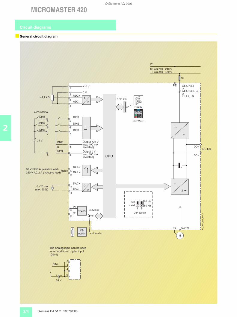
General circuit diagram
PE
SI
PE L/L1, N/L2
L/L1, N/L2, L3
L1, L2, L3
=
3 ~
PE U,V,W
M
A
D
+10 V
0 V
0 - 20 mA
max. 500 Ω
CPU
RS485
D
A
~
=
ADC+
ADC-
DIN1
DIN2
DIN3
DAC+
DAC-
P+
N-
RL1-B
RL1-C
1
2
3
4
5
6
7
8
9
12
13
14
15
10
11
≥ 4,7 kΩ
DC+
DC−
DIN4
2
3
4
9
24 V
–+
1 2
60 Hz
50 Hz
150.00
DIN1
DIN2
DIN3
5
6
7
9
NPN
PNP24 V
+
_
BOP/AOP
RS232
1/3 AC 200 - 240 V3 AC 380 - 480 V
G_
DA
51
_E
N_
00
01
1Not
used
Output 0 Vmax. 100 mA(isolated)
30 V DC/5 A (resistive load)
250 V AC/2 A (inductive load)
Output +24 Vmax. 100 mA(isolated)
or
or
automatic
DC link
The analog input can be used
as an additional digital input
(DIN4)
DIP switch
or
24 V external
BOP link
COM link
Relay
CB
option
Circuit diagrams
© Siemens AG 2007

Siemens DA 51.2 · 2007/2008 2/5
MICROMASTER 420
2
Terminal connection diagram
5 7 86 9
1 3 42
10 11
RL1-B RL1-C
+10 V 0 V ADC+ ADC-
12 14 1513
DAC+ DAC- P+ N-
DIN1 DIN2 DIN3 +24 V 0 V
NPNPNP
Output relayRL1
Analog output RS-485(USS protocol)
Voltagesupply 10 V
Analog input
Output relay contacts
Digital inputs PNP or NPNpossible
(isolated)
G_DA51_EN_05106
View A
View A
Mains connections
Motor connections
DC link terminals
Example frame size A
Circuit diagrams
© Siemens AG 2007

2/6 Siemens DA 51.2 · 2007/2008
MICROMASTER 420
2
MICROMASTER 420 inverter
Mains voltage and power ranges
1 AC 200 V to 240 V ± 10 %3 AC 200 V to 240 V ± 10 %3 AC 380 V to 480 V ± 10 %
0.12 kW to 3 kW0.12 kW to 5.5 kW0.37 kW to 11 kW
Power frequency 47 Hz to 63 HzOutput frequency 0 Hz to 650 HzPower factor 0.95Inverter efficiency 96 % to 97 % (Further information is available on the Internet at:
http://support.automation.siemens.com/WW/view/en/22978972)Overload capability Overload current 1.5 x rated output current (i.e. 150 % overload capability) for 60 s, cycle time 300 s Inrush current Less than rated input currentControl method Linear V/f-characteristic; quadratic V/f characteristic; multipoint characteristic
(programmable V/f characteristic); flux current control (FCC)Pulse frequency 16 kHz (standard with 1/3 AC 230 V)
4 kHz (standard with 3 AC 400 V)2 kHz to 16 kHz (in 2 kHz steps)
Fixed frequencies 7, programmableSkip frequency ranges 4, programmableSetpoint resolution 0.01 Hz digital
0.01 Hz serial10 bit analog
Digital inputs 3 fully programmable isolated digital inputs; switchable PNP/NPNAnalog input 1, for setpoint or PI controller (0 V to 10 V, scaleable or for use as 4th digital input)Relay outputs 1, programmable, 30 V DC/5 A (resistive load); 250 V AC/2A (inductive load)Analog output 1, programmable (0 mA to 20 mA)Serial interfaces RS-485, optional RS-232Motor cable lengths
without output choke
without output choke
max. 50 m (shielded)max. 100 m (unshielded)see variant dependent options
Electromagnetic compatibility Inverter available with internal EMC filter Class A; available as options are EMC filters to EN 55 011, Class A or Class B
Braking DC braking, compound brakingDegree of protection IP20Operating temperature –10 °C to +50 °C (+14 °F to +122 °F)Storage temperature –40 °C to +70 °C (–40 °F to +158 °F)Relative humidity 95 % (non-condensing)Installation altitude Up to 1000 m above sea level
without deratingStandard SCCR (Short Circuit Current Rating) 1)
10 kA
Protection features for • Undervoltage• Overvoltage• Overload• Earth faults • Short circuit• Stall prevention• Locked motor protection• Motor overtemperature• Inverter overtemperature• Parameter interlock
Compliance with standards u, cu, >, c-tick
> marking Conformity with low-voltage directive 73/23/EECCooling-air volumetric flow required, dimensions and weights (without options)
Frame size (FS)
ABC
Cooling-air volumetric flow required (l/s)/(CFM) 4.8/10.2 24/51 54.9/116.3
H x W x D (mm)
173 x 73 x 149202 x 149 x 172245 x 185 x 195
Weight, approx. (kg)
1.03.35.0
CFM: Cubic Feet per Minute
1) Applies to industrial control cabinet installations to NEC article 409/UL 508A.
For further information, visit us on the Internet at:
http://support.automation.siemens.com/WW/view/en/23995621
Technical data
© Siemens AG 2007

Siemens DA 51.2 · 2007/2008 2/7
MICROMASTER 420
2
Derating data
Pulse frequency
Operating temperature
Installation altitude above sea level
Output(for 3 AC 400 V)
Rated output current in Afor a pulse frequency of
kW 4 kHz 6 kHz 8 kHz 10 kHz 12 kHz 14 kHz 16 kHz0.37 1.2 1.2 1.2 1.2 1.2 1.2 1.10.55 1.6 1.6 1.6 1.6 1.6 1.6 1.10.75 2.1 2.1 2.1 2.1 1.6 1.6 1.11.1 3.0 3.0 2.7 2.7 1.6 1.6 1.11.5 4.0 4.0 2.7 2.7 1.6 1.6 1.12.2 5.9 5.9 5.1 5.1 3.6 3.6 2.63.0 7.7 7.7 5.1 5.1 3.6 3.6 2.64.0 10.2 10.2 6.7 6.7 4.8 4.8 3.65.5 13.2 13.2 13.2 13.2 9.6 9.6 7.57.5 19.0 18.4 13.2 13.2 9.6 9.6 7.5
11 26.0 26.0 17.9 17.9 13.5 13.5 10.4
Permissible output current in % of the rated output current
2000
60
0 40000
20
40
80
DA51-5018c
100
1000
%
3000 m
Rat
ed o
utpu
t cur
rent
Operational altitude
A
2000
60
0 40000
20
40
80
DA51-5019b
100
1000
%
3000 m
77
Mai
ns v
olta
ge
Operational altitude
A
Permissible mains voltage in % of the max. possible mains voltage
Technical data
© Siemens AG 2007

2/8 Siemens DA 51.2 · 2007/2008
MICROMASTER 420
2
MICROMASTER 420 inverter
Output Rated input current 1)
Rated output current
Frame size Order No.
kW hp A A (FS)
MICROMASTER 420 without filter 3)
MICROMASTER 420 with internal filter Class A 2)
Mains operating voltage 1 AC 200 V to 240 V0.12 0.16 1.8 0.9 A 6SE6420-2UC11-2AA1 6SE6420-2AB11-2AA10.25 0.33 3.2 1.7 A 6SE6420-2UC12-5AA1 6SE6420-2AB12-5AA10.37 0.50 4.6 2.3 A 6SE6420-2UC13-7AA1 6SE6420-2AB13-7AA10.55 0.75 6.2 3.0 A 6SE6420-2UC15-5AA1 6SE6420-2AB15-5AA10.75 1.0 8.2 3.9 A 6SE6420-2UC17-5AA1 6SE6420-2AB17-5AA11.1 1.5 11.0 5.5 B 6SE6420-2UC21-1BA1 6SE6420-2AB21-1BA11.5 2.0 14.4 7.4 B 6SE6420-2UC21-5BA1 6SE6420-2AB21-5BA12.2 3.0 20.2 10.4 B 6SE6420-2UC22-2BA1 6SE6420-2AB22-2BA13.0 4.0 35.5 13.6 C 6SE6420-2UC23-0CA1 6SE6420-2AB23-0CA1
Mains operating voltage 3 AC 200 V to 240 V0.12 0.16 1.1 0.9 A 6SE6420-2UC11-2AA1 –0.25 0.33 1.9 1.7 A 6SE6420-2UC12-5AA1 –0.37 0.50 2.7 2.3 A 6SE6420-2UC13-7AA1 –0.55 0.75 3.6 3.0 A 6SE6420-2UC15-5AA1 –0.75 1.0 4.7 3.9 A 6SE6420-2UC17-5AA1 –1.1 1.5 6.4 5.5 B 6SE6420-2UC21-1BA1 –1.5 2.0 8.3 7.4 B 6SE6420-2UC21-5BA1 –2.2 3.0 11.7 10.4 B 6SE6420-2UC22-2BA1 –3.0 4.0 15.6 13.6 C 6SE6420-2UC23-0CA1 6SE6420-2AC23-0CA14.0 5.0 19.7 17.5 C 6SE6420-2UC24-0CA1 6SE6420-2AC24-0CA15.5 7.5 26.5 22.0 C 6SE6420-2UC25-5CA1 6SE6420-2AC25-5CA1
Mains operating voltage 3 AC 380 V to 480 V0.37 0.50 2.2 1.2 A 6SE6420-2UD13-7AA1 –0.55 0.75 2.8 1.6 A 6SE6420-2UD15-5AA1 –0.75 1.0 3.7 2.1 A 6SE6420-2UD17-5AA1 –1.1 1.5 4.9 3.0 A 6SE6420-2UD21-1AA1 –1.5 2.0 5.9 4.0 A 6SE6420-2UD21-5AA1 –2.2 3.0 7.5 5.9 B 6SE6420-2UD22-2BA1 6SE6420-2AD22-2BA13.0 4.0 10.0 7.7 B 6SE6420-2UD23-0BA1 6SE6420-2AD23-0BA14.0 5.0 12.8 10.2 B 6SE6420-2UD24-0BA1 6SE6420-2AD24-0BA15.5 7.5 15.6 13.2 C 6SE6420-2UD25-5CA1 6SE6420-2AD25-5CA17.5 10.0 22.0 19.0 C 6SE6420-2UD27-5CA1 6SE6420-2AD27-5CA1
11 15.0 32.3 26.0 C 6SE6420-2UD31-1CA1 6SE6420-2AD31-1CA1
See Appendix for note on or-dering.
All MICROMASTER 420 invert-ers are supplied with a Status Display Panel (SDP). A BOP, AOP or other options have to be ordered separately (see Pages 2/12 to 2/16).
Motors for MICROMASTER 420
Catalog D 81.1 contains se-lection and ordering data for motors which are particularly suitable for operation with the MICROMASTER 420 inverters(see Appendix for overview).
This catalog is suitable for IEC motors. For motors according to US standards (NEMA) please refer to Catalog D 81.2 U.S./Canada (see Appendix for overview) and to:http://www.sea.siemens.com/motors
1) Supplementary conditions: Input current at rated operating point, applicable at short-circuit voltage of the supply Usc = 2 % with reference to the
inverter rated power and rated mains voltage of 240 V or 400 V without a line commutating choke.
2) Use of MICROMASTER invert-ers with internal filter is not per-missible on non-grounded (IT) mains supplies.
3) Acc. to EMC EN 61800-3 gen-erally suited to heavy industrial applications. For details please refer to Appendix on page A/4.
Selection and ordering data
© Siemens AG 2007

Siemens DA 51.2 · 2007/2008 2/9
MICROMASTER 420
2
Overview
EMC filter, Class A
Filter for inverters without an internal filter for– 3 AC 200 V to 240 V,
frame sizes A and B– 3 AC 380 V to 480 V,
frame size A.
All other inverters can be sup-plied with an internal Class A filter.
The requirements are fulfilled using shielded cables with a max. length of 25 m.
EMC filter, Class B
Filter for inverters without an internal filter for– 3 AC 200 V to 240 V,
frame sizes A and B– 3 AC 380 V to 480 V,
frame size A.
With this filter, the inverter complies with the emission standard EN 55 011, Class B for conducted interference emissions.
The requirements are fulfilled using shielded cables with a max. length of 25 m.
Additional EMC filter, Class B
Available for inverters with an internal Class A EMC filter.
With this filter, the inverter complies with the emission standard EN 55 011, Class B for conducted interference emissions.
The requirements are fulfilled using shielded cables with a max. length of 25 m.
Filter Class B with low leakage currents
EMC filter for 1 AC 200 V to 240 V inverters, frame sizes A and B, without an internal EMC filter Class A.
With this filter, the inverter complies with the emission standard EN 55 011, Class B for conducted interference emissions. The leakage cur-rents are reduced to < 3.5 mA.
The requirements are fulfilled using shielded cables with a max. length of 5 m.
Leakage currents:
The leakage currents of the in-verters with/without filter (inter-nal/external) may exceed 30 mA. Typical values in prac-tice are between 10 mA and 50 mA. The exact values de-pend on the design, environ-ment and cable lengths. Inter-ference-free operation with re-sidual current operated devic-es with a trigger value of 30 mA cannot be guaranteed. However, operation with resid-ual current circuit-breakers with a trigger value of 300 mA is possible. Please refer to the Instruction Manual for details.
LC filter
The LC filter limits the rate of rise of voltage and the capac-itive charge/discharge cur-rents which usually occur with inverter operation. This means that much longer shielded mo-tor cables are possible when using LC filters and the ser-vice life of the motor achieves values similar to those with direct mains operation. Use of an output choke isn’t required with that.
Please note when using LC filters:
• Only V/f, FCC control per-missible
• Please observe the derating of 15 % when selecting the appropriate inverter
• Operation only permissible with 4 kHz pulse frequency
• The output frequency is lim-ited to 150 Hz
• Operation and commission-ing only with connected mo-tor as the LC filter is not idling-proof!
The LC filters can be used for all MICROMASTER 420 invert-ers of frame sizes A to C.
Line commutating choke
Line commutating chokes are used to smooth voltage peaks or to bridge commutat-ing dips. In addition, line com-mutating chokes reduce the effects of harmonics on the in-verter and the power supply. If the line impedance is <1 %, a line commutating choke must be used in order to reduce the current peaks.
In line with EN 61 000-3-2 reg-ulations “Limits for harmonic currents with device input cur-rent 16 A per phase”, there are special aspects for drives with 250 W to 550 W and 230 V single-phase supplies which can be used in non-in-dustrial applications (1st envi-ronment).
For devices with 250 W and 370 W, it is necessary either to fit the recommended input chokes or to apply to the pow-er utility company for authori-zation to connect the devices to the public power supply. No limits are currently defined in the EN 61 000-3-2 standard for professionally used devic-es with a connected load > 1 kW which means that the inverters with an output power 0.75 kW comply with the EN 61 000-3-2 standard.
However, in accordance with the regulations of EN 61000-3-12 “Limits for harmonic cur-rents > 16 A and 75 A per phase” an approval is neces-sary from the power supplier for drives that are intended to be connected to the public low-voltage network. Please refer to the Operating Instruc-tions for the values of the har-monic currents.
Output choke
Output chokes can be sup-plied for reducing the capaci-tive currents and dV/dt in the case of motor cables > 50 m (shielded) or > 100 m (un-shielded).
For max. permissible cable lengths, see Technical Data.
Gland plate
The gland plate facilitates the shield connection of power and control cables and en-sures optimum EMC perfor-mance.
OptionsVariant dependent options
© Siemens AG 2007

2/10 Siemens DA 51.2 · 2007/2008
MICROMASTER 420
2
Technical data
LC filter
Max. permissible cable lengths from the motor to the inverter when using output chokes
Mains voltage 3 AC 380 V to 480 VCurrent (at 40 °C/50 °C) for frame size A
for frame size Bfor frame size C
4.5 A/ 4.1 A11.2 A/10.2 A32.6 A/29.7 A
Limiting of motor overvoltage 1078 VdV/dt limiting 500 V/sPulse frequency 4 kHzMax. motor frequency 150 HzMax. permissible motor cable lengths
shieldedunshielded
200 m300 m
Insulation strength Overvoltage category III to VDE 0110Electromagnetic compatibility Up to 200 m motor cable length with emissions to Class A according to EN 55 011 in
conjunction with filtered inverters and unshielded cablesConformity CE according to the low-voltage directive 73/23/EECApprovals UL available soonStrain resistance EN 60 068-2-31Humidity 95 % humidity, non-condensingDegree of protection IP20 (to EN 60529)Insulation class H (180 °C)Permissible temperature Operation
Storage
–10 °C to +40 °C (+14 °F to +104 °F) 100 % Pnto +50 °C (to +122 °F) 80 % Pn
–25 °C to +70 °C (–13 °F to +158 °F)Installation altitude up to 2000 m
2000 to 4000 m100 % Pn62.5 % Pn
Mounting position Footprint or suspendedFree space Top
BottomSide
100 mm100 mm100 mm
Connection system Input, litz wire or terminalOutput, terminals
1U1, 1V1, 1W11U2, 1V2, 1W2
Torque for power conductor connections 1.5 Nm to 1.8 NmWeight, approx. for frame size A
for frame size Bfor frame size C
7 kg11 kg29 kg
The following table shows the maximum permissible cable lengths from the motor to the inverter when using output chokes.
Frame size Output choke Max. permissible motor cable lengths (shielded/unshielded)for a mains voltage of
(FS) Type 200 V to 240 V ± 10 % 380 V to 400 V ± 10 % 401 V to 480 V ± 10 %A 6SE6400-3TC00-4AD3 200 m/300 m – –A 6SE6400-3TC00-4AD2 200 m/300 m 150 m/225 m 100 m/150 mB 6SE6400-3TC01-0BD3 200 m/300 m 150 m/225 m 100 m/150 mC 6SE6400-3TC03-2CD3 200 m/300 m 200 m/300 m 100 m/150 m
OptionsVariant dependent options
© Siemens AG 2007

Siemens DA 51.2 · 2007/2008 2/11
MICROMASTER 420
2
Design
General installation instructions
Availability of the options as footprint components
Recommended combinations of inverters and options
A maximum of two footprint components plus inverter are permissible.
If an LC filter is used, it must be mounted directly on the wall of the control cabinet due to weight reasons. If an LC filter of frame size C is used, therefore, only one footprint component is per-missible. If a line choke and LC filter are used, the line choke must be located on the left of the inverter. Required distance between line choke and inverter: 75 mm.
The EMC filter must be mounted directly below the frequency inverter if pos-sible.
If mounted on the side, the line-side components are to be mounted to the left of the frequency inverter whereas the output-side compon-ents are to be mounted to the right of the frequency inverter.
Frame sizeA B C
Line commutating choke
EMC filter
LC filter
Output choke
Frequency inverter Footprint Mounted on sideFrame size Position 1 Position 2 To the left of the inverter
(for line-side components)To the right of the inverter (for output-side compon-ents)
A and B EMC filter Line commutating choke – Output chokeEMC filter orLine commutating choke
Output choke orLC filter
– –
C EMC filter Line commutating choke – Output chokeEMC filter orLine commutating choke
Output choke – –
LC filter – EMC filter and/orLine commutating choke
–
Example of installation with frequency inverter, EMC filter (position 1) and line choke (position 2)
OptionsVariant dependent options
© Siemens AG 2007

2/12 Siemens DA 51.2 · 2007/2008
MICROMASTER 420
2
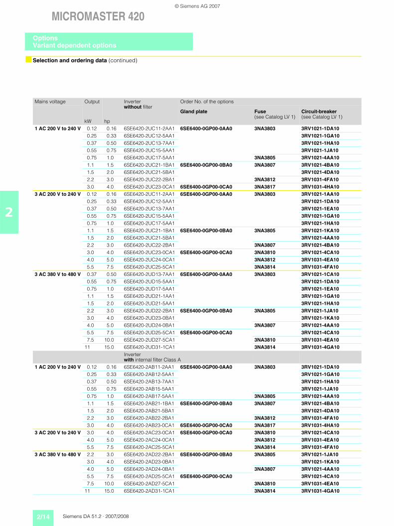
Selection and ordering data
The options listed here (filters, chokes, gland plates, fuses, and circuit-breakers) must be selected to match the inverter.
The inverter and the associat-ed options have the same volt-age ratings. Alternatively fus-es and circuit-breakers can be
provided. Both provide short circuit protection of the invert-er supply line and the inverter. A semiconductor protection of
the inverter with the suggest-ed 3NA... fuses and the 3RV... circuit-breakers is not envis-aged.
Mains voltage Output
kW hp
Inverterwithout filter
Order No. of the options
EMC filterClass A
EMC filterClass B
Additional EMC filter, Class B
1 AC 200 V to 240 V 0.12 0.16 6SE6420-2UC11-2AA1 – 6SE6400-2FL01-0AB0with low leakage currents
–0.25 0.33 6SE6420-2UC12-5AA1 – –0.37 0.50 6SE6420-2UC13-7AA1 – –0.55 0.75 6SE6420-2UC15-5AA1 – –0.75 1.0 6SE6420-2UC17-5AA1 – –1.1 1.5 6SE6420-2UC21-1BA1 – 6SE6400-2FL02-6BB0
with low leakage currents
–1.5 2.0 6SE6420-2UC21-5BA1 – –2.2 3.0 6SE6420-2UC22-2BA1 – –3.0 4.0 6SE6420-2UC23-0CA1 – – –
3 AC 200 V to 240 V 0.12 0.16 6SE6420-2UC11-2AA1 6SE6400-2FA00-6AD0 6SE6400-2FB00-6AD0 –0.25 0.33 6SE6420-2UC12-5AA1 –0.37 0.50 6SE6420-2UC13-7AA1 –0.55 0.75 6SE6420-2UC15-5AA1 –0.75 1.0 6SE6420-2UC17-5AA1 –1.1 1.5 6SE6420-2UC21-1BA1 6SE6400-2FA01-4BC0 6SE6400-2FB01-4BC0 –1.5 2.0 6SE6420-2UC21-5BA1 –2.2 3.0 6SE6420-2UC22-2BA1 –3.0 4.0 6SE6420-2UC23-0CA1 – – –4.0 5.0 6SE6420-2UC24-0CA1 – – –5.5 7.5 6SE6420-2UC25-5CA1 – – –
3 AC 380 V to 480 V 0.37 0.50 6SE6420-2UD13-7AA1 6SE6400-2FA00-6AD0 6SE6400-2FB00-6AD0 –0.55 0.75 6SE6420-2UD15-5AA1 –0.75 1.0 6SE6420-2UD17-5AA1 –1.1 1.5 6SE6420-2UD21-1AA1 –1.5 2.0 6SE6420-2UD21-5AA1 –2.2 3.0 6SE6420-2UD22-2BA1 – – –3.0 4.0 6SE6420-2UD23-0BA1 – – –4.0 5.0 6SE6420-2UD24-0BA1 – – –5.5 7.5 6SE6420-2UD25-5CA1 – – –7.5 10.0 6SE6420-2UD27-5CA1 – – –
11 15.0 6SE6420-2UD31-1CA1 – – –Inverter with internal filter Class A
1 AC 200 V to 240 V 0.12 0.16 6SE6420-2AB11-2AA1 – – 6SE6400-2FS01-0AB00.25 0.33 6SE6420-2AB12-5AA1 – –0.37 0.50 6SE6420-2AB13-7AA1 – –0.55 0.75 6SE6420-2AB15-5AA1 – –0.75 1.0 6SE6420-2AB17-5AA1 – –1.1 1.5 6SE6420-2AB21-1BA1 – – 6SE6400-2FS02-6BB01.5 2.0 6SE6420-2AB21-5BA1 – –2.2 3.0 6SE6420-2AB22-2BA1 – –3.0 4.0 6SE6420-2AB23-0CA1 – – 6SE6400-2FS03-5CB0
3 AC 200 V to 240 V 3.0 4.0 6SE6420-2AC23-0CA1 – – 6SE6400-2FS03-8CD04.0 5.0 6SE6420-2AC24-0CA1 – –5.5 7.5 6SE6420-2AC25-5CA1 – –
3 AC 380 V to 480 V 2.2 3.0 6SE6420-2AD22-2BA1 – – 6SE6400-2FS01-6BD03.0 4.0 6SE6420-2AD23-0BA1 – –4.0 5.0 6SE6420-2AD24-0BA1 – –5.5 7.5 6SE6420-2AD25-5CA1 – – 6SE6400-2FS03-8CD07.5 10.0 6SE6420-2AD27-5CA1 – –
11 15.0 6SE6420-2AD31-1CA1 – –
OptionsVariant dependent options
© Siemens AG 2007

Siemens DA 51.2 · 2007/2008 2/13
MICROMASTER 420
2
Selection and ordering data (continued)
All options are certified to u, except fuses. The fuses of Type 3NA3 are recommended for Europe.
Additional information on the listed fuses and circuit-breakers can be found in Catalogs LV 1 and LV 1 T.
Use in America requires u-listed fuses such as the Class NON/NOS range from Bussmann.
Mains voltage Output
kW hp
Inverterwithout filter
Order No. of the options
Line commutating choke
LC filter Output choke
1 AC 200 V to 240 V 0.12 0.16 6SE6420-2UC11-2AA1 6SE6400-3CC00-4AB3 – 6SE6400-3TC00-4AD30.25 0.33 6SE6420-2UC12-5AA1 –0.37 0.50 6SE6420-2UC13-7AA1 6SE6400-3CC01-0AB3 –0.55 0.75 6SE6420-2UC15-5AA1 –0.75 1.0 6SE6420-2UC17-5AA1 –1.1 1.5 6SE6420-2UC21-1BA1 6SE6400-3CC02-6BB3 – 6SE6400-3TC01-0BD31.5 2.0 6SE6420-2UC21-5BA1 –2.2 3.0 6SE6420-2UC22-2BA1 –3.0 4.0 6SE6420-2UC23-0CA1 6SE6400-3CC03-5CB3 – 6SE6400-3TC03-2CD3
3 AC 200 V to 240 V 0.12 0.16 6SE6420-2UC11-2AA1 6SE6400-3CC00-3AC3 – 6SE6400-3TC00-4AD30.25 0.33 6SE6420-2UC12-5AA1 –0.37 0.50 6SE6420-2UC13-7AA1 6SE6400-3CC00-5AC3 –0.55 0.75 6SE6420-2UC15-5AA1 –0.75 1.0 6SE6420-2UC17-5AA1 –1.1 1.5 6SE6420-2UC21-1BA1 6SE6400-3CC00-8BC3 – 6SE6400-3TC01-0BD31.5 2.0 6SE6420-2UC21-5BA1 6SE6400-3CC01-4BD3 –2.2 3.0 6SE6420-2UC22-2BA1 –3.0 4.0 6SE6420-2UC23-0CA1 6SE6400-3CC01-7CC3 – 6SE6400-3TC03-2CD34.0 5.0 6SE6420-2UC24-0CA1 6SE6400-3CC03-5CD3 –5.5 7.5 6SE6420-2UC25-5CA1 –
3 AC 380 V to 480 V 0.37 0.50 6SE6420-2UD13-7AA1 6SE6400-3CC00-2AD3 6SE6400-3TD00-4AD0 6SE6400-3TC00-4AD20.55 0.75 6SE6420-2UD15-5AA10.75 1.0 6SE6420-2UD17-5AA1 6SE6400-3CC00-4AD31.1 1.5 6SE6420-2UD21-1AA11.5 2.0 6SE6420-2UD21-5AA1 6SE6400-3CC00-6AD32.2 3.0 6SE6420-2UD22-2BA1 6SE6400-3CC01-0BD3 6SE6400-3TD01-0BD0 6SE6400-3TC01-0BD33.0 4.0 6SE6420-2UD23-0BA14.0 5.0 6SE6420-2UD24-0BA1 6SE6400-3CC01-4BD35.5 7.5 6SE6420-2UD25-5CA1 6SE6400-3CC02-2CD3 6SE6400-3TD03-2CD0 6SE6400-3TC03-2CD37.5 10.0 6SE6420-2UD27-5CA1
11 15.0 6SE6420-2UD31-1CA1 6SE6400-3CC03-5CD3Inverter with internal filter Class A
1 AC 200 V to 240 V 0.12 0.16 6SE6420-2AB11-2AA1 6SE6400-3CC00-4AB3 – 6SE6400-3TC00-4AD30.25 0.33 6SE6420-2AB12-5AA1 –0.37 0.50 6SE6420-2AB13-7AA1 6SE6400-3CC01-0AB3 –0.55 0.75 6SE6420-2AB15-5AA1 –0.75 1.0 6SE6420-2AB17-5AA1 –1.1 1.5 6SE6420-2AB21-1BA1 6SE6400-3CC02-6BB3 – 6SE6400-3TC01-0BD31.5 2.0 6SE6420-2AB21-5BA1 –2.2 3.0 6SE6420-2AB22-2BA1 –3.0 4.0 6SE6420-2AB23-0CA1 6SE6400-3CC03-5CB3 – 6SE6400-3TC03-2CD3
3 AC 200 V to 240 V 3.0 4.0 6SE6420-2AC23-0CA1 6SE6400-3CC01-7CC3 – 6SE6400-3TC03-2CD34.0 5.0 6SE6420-2AC24-0CA1 6SE6400-3CC03-5CD3 –5.5 7.5 6SE6420-2AC25-5CA1 –
3 AC 380 V to 480 V 2.2 3.0 6SE6420-2AD22-2BA1 6SE6400-3CC01-0BD3 6SE6400-3TD01-0BD0 6SE6400-3TC01-0BD33.0 4.0 6SE6420-2AD23-0BA14.0 5.0 6SE6420-2AD24-0BA1 6SE6400-3CC01-4BD35.5 7.5 6SE6420-2AD25-5CA1 6SE6400-3CC02-2CD3 6SE6400-3TD03-2CD0 6SE6400-3TC03-2CD37.5 10.0 6SE6420-2AD27-5CA1
11 15.0 6SE6420-2AD31-1CA1 6SE6400-3CC03-5CD3
OptionsVariant dependent options
© Siemens AG 2007
2/14 Siemens DA 51.2 · 2007/2008
MICROMASTER 420
2
Selection and ordering data (continued)
Mains voltage Output
kW hp
Inverterwithout filter
Order No. of the options
Gland plate Fuse(see Catalog LV 1)
Circuit-breaker(see Catalog LV 1)
1 AC 200 V to 240 V 0.12 0.16 6SE6420-2UC11-2AA1 6SE6400-0GP00-0AA0 3NA3803 3RV1021-1DA100.25 0.33 6SE6420-2UC12-5AA1 3RV1021-1GA100.37 0.50 6SE6420-2UC13-7AA1 3RV1021-1HA100.55 0.75 6SE6420-2UC15-5AA1 3RV1021-1JA100.75 1.0 6SE6420-2UC17-5AA1 3NA3805 3RV1021-4AA101.1 1.5 6SE6420-2UC21-1BA1 6SE6400-0GP00-0BA0 3NA3807 3RV1021-4BA101.5 2.0 6SE6420-2UC21-5BA1 3RV1021-4DA102.2 3.0 6SE6420-2UC22-2BA1 3NA3812 3RV1031-4FA103.0 4.0 6SE6420-2UC23-0CA1 6SE6400-0GP00-0CA0 3NA3817 3RV1031-4HA10
3 AC 200 V to 240 V 0.12 0.16 6SE6420-2UC11-2AA1 6SE6400-0GP00-0AA0 3NA3803 3RV1021-1AA100.25 0.33 6SE6420-2UC12-5AA1 3RV1021-1DA100.37 0.50 6SE6420-2UC13-7AA1 3RV1021-1EA100.55 0.75 6SE6420-2UC15-5AA1 3RV1021-1GA100.75 1.0 6SE6420-2UC17-5AA1 3RV1021-1HA101.1 1.5 6SE6420-2UC21-1BA1 6SE6400-0GP00-0BA0 3NA3805 3RV1021-1KA101.5 2.0 6SE6420-2UC21-5BA1 3RV1021-4AA102.2 3.0 6SE6420-2UC22-2BA1 3NA3807 3RV1021-4BA103.0 4.0 6SE6420-2UC23-0CA1 6SE6400-0GP00-0CA0 3NA3810 3RV1021-4CA104.0 5.0 6SE6420-2UC24-0CA1 3NA3812 3RV1031-4EA105.5 7.5 6SE6420-2UC25-5CA1 3NA3814 3RV1031-4FA10
3 AC 380 V to 480 V 0.37 0.50 6SE6420-2UD13-7AA1 6SE6400-0GP00-0AA0 3NA3803 3RV1021-1CA100.55 0.75 6SE6420-2UD15-5AA1 3RV1021-1DA100.75 1.0 6SE6420-2UD17-5AA1 3RV1021-1EA101.1 1.5 6SE6420-2UD21-1AA1 3RV1021-1GA101.5 2.0 6SE6420-2UD21-5AA1 3RV1021-1HA102.2 3.0 6SE6420-2UD22-2BA1 6SE6400-0GP00-0BA0 3NA3805 3RV1021-1JA103.0 4.0 6SE6420-2UD23-0BA1 3RV1021-1KA104.0 5.0 6SE6420-2UD24-0BA1 3NA3807 3RV1021-4AA105.5 7.5 6SE6420-2UD25-5CA1 6SE6400-0GP00-0CA0 3RV1021-4CA107.5 10.0 6SE6420-2UD27-5CA1 3NA3810 3RV1031-4EA10
11 15.0 6SE6420-2UD31-1CA1 3NA3814 3RV1031-4GA10Inverter with internal filter Class A
1 AC 200 V to 240 V 0.12 0.16 6SE6420-2AB11-2AA1 6SE6400-0GP00-0AA0 3NA3803 3RV1021-1DA100.25 0.33 6SE6420-2AB12-5AA1 3RV1021-1GA100.37 0.50 6SE6420-2AB13-7AA1 3RV1021-1HA100.55 0.75 6SE6420-2AB15-5AA1 3RV1021-1JA100.75 1.0 6SE6420-2AB17-5AA1 3NA3805 3RV1021-4AA101.1 1.5 6SE6420-2AB21-1BA1 6SE6400-0GP00-0BA0 3NA3807 3RV1021-4BA101.5 2.0 6SE6420-2AB21-5BA1 3RV1021-4DA102.2 3.0 6SE6420-2AB22-2BA1 3NA3812 3RV1031-4FA103.0 4.0 6SE6420-2AB23-0CA1 6SE6400-0GP00-0CA0 3NA3817 3RV1031-4HA10
3 AC 200 V to 240 V 3.0 4.0 6SE6420-2AC23-0CA1 6SE6400-0GP00-0CA0 3NA3810 3RV1021-4CA104.0 5.0 6SE6420-2AC24-0CA1 3NA3812 3RV1031-4EA105.5 7.5 6SE6420-2AC25-5CA1 3NA3814 3RV1031-4FA10
3 AC 380 V to 480 V 2.2 3.0 6SE6420-2AD22-2BA1 6SE6400-0GP00-0BA0 3NA3805 3RV1021-1JA103.0 4.0 6SE6420-2AD23-0BA1 3RV1021-1KA104.0 5.0 6SE6420-2AD24-0BA1 3NA3807 3RV1021-4AA105.5 7.5 6SE6420-2AD25-5CA1 6SE6400-0GP00-0CA0 3RV1021-4CA107.5 10.0 6SE6420-2AD27-5CA1 3NA3810 3RV1031-4EA10
11 15.0 6SE6420-2AD31-1CA1 3NA3814 3RV1031-4GA10
OptionsVariant dependent options
© Siemens AG 2007
Siemens DA 51.2 · 2007/2008 2/15
MICROMASTER 420
2
Overview
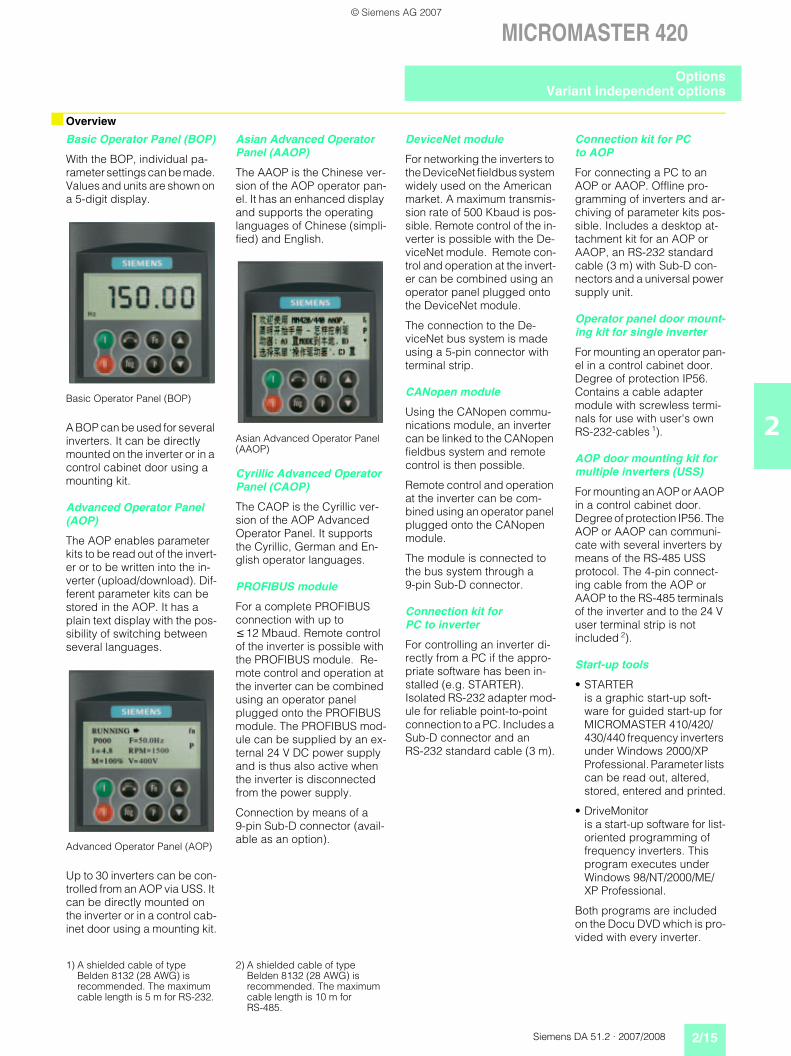
Basic Operator Panel (BOP)
With the BOP, individual pa-rameter settings can be made. Values and units are shown on a 5-digit display.
Basic Operator Panel (BOP)
A BOP can be used for several inverters. It can be directly mounted on the inverter or in a control cabinet door using a mounting kit.
Advanced Operator Panel (AOP)
The AOP enables parameter kits to be read out of the invert-er or to be written into the in-verter (upload/download). Dif-ferent parameter kits can be stored in the AOP. It has a plain text display with the pos-sibility of switching between several languages.
Advanced Operator Panel (AOP)
Up to 30 inverters can be con-trolled from an AOP via USS. It can be directly mounted on the inverter or in a control cab-inet door using a mounting kit.
Asian Advanced Operator Panel (AAOP)
The AAOP is the Chinese ver-sion of the AOP operator pan-el. It has an enhanced display and supports the operating languages of Chinese (simpli-fied) and English.
Asian Advanced Operator Panel (AAOP)
Cyrillic Advanced Operator Panel (CAOP)
The CAOP is the Cyrillic ver-sion of the AOP Advanced Operator Panel. It supports the Cyrillic, German and En-glish operator languages.
PROFIBUS module
For a complete PROFIBUS connection with up to 12 Mbaud. Remote control of the inverter is possible with the PROFIBUS module. Re-mote control and operation at the inverter can be combined using an operator panel plugged onto the PROFIBUS module. The PROFIBUS mod-ule can be supplied by an ex-ternal 24 V DC power supply and is thus also active when the inverter is disconnected from the power supply.
Connection by means of a 9-pin Sub-D connector (avail-able as an option).
DeviceNet module
For networking the inverters to the DeviceNet fieldbus system widely used on the American market. A maximum transmis-sion rate of 500 Kbaud is pos-sible. Remote control of the in-verter is possible with the De-viceNet module. Remote con-trol and operation at the invert-er can be combined using an operator panel plugged onto the DeviceNet module.
The connection to the De-viceNet bus system is made using a 5-pin connector with terminal strip.
CANopen module
Using the CANopen commu-nications module, an inverter can be linked to the CANopen fieldbus system and remote control is then possible.
Remote control and operation at the inverter can be com-bined using an operator panel plugged onto the CANopen module.
The module is connected to the bus system through a 9-pin Sub-D connector.
Connection kit for PC to inverter
For controlling an inverter di-rectly from a PC if the appro-priate software has been in-stalled (e.g. STARTER). Isolated RS-232 adapter mod-ule for reliable point-to-point connection to a PC. Includes a Sub-D connector and an RS-232 standard cable (3 m).
Connection kit for PC to AOP
For connecting a PC to an AOP or AAOP. Offline pro-gramming of inverters and ar-chiving of parameter kits pos-sible. Includes a desktop at-tachment kit for an AOP or AAOP, an RS-232 standard cable (3 m) with Sub-D con-nectors and a universal power supply unit.
Operator panel door mount-ing kit for single inverter
For mounting an operator pan-el in a control cabinet door. Degree of protection IP56. Contains a cable adapter module with screwless termi-nals for use with user's own RS-232-cables 1).
AOP door mounting kit for multiple inverters (USS)
For mounting an AOP or AAOP in a control cabinet door. Degree of protection IP56. The AOP or AAOP can communi-cate with several inverters by means of the RS-485 USS protocol. The 4-pin connect-ing cable from the AOP or AAOP to the RS-485 terminals of the inverter and to the 24 V user terminal strip is not included 2).
Start-up tools
• STARTER is a graphic start-up soft-ware for guided start-up for MICROMASTER 410/420/430/440 frequency inverters under Windows 2000/XP Professional. Parameter lists can be read out, altered, stored, entered and printed.
• DriveMonitor is a start-up software for list-oriented programming of frequency inverters. This program executes under Windows 98/NT/2000/ME/XP Professional.
Both programs are included on the Docu DVD which is pro-vided with every inverter.
1) A shielded cable of type Belden 8132 (28 AWG) is recommended. The maximum cable length is 5 m for RS-232.
2) A shielded cable of type Belden 8132 (28 AWG) is recommended. The maximum cable length is 10 m for RS-485.
OptionsVariant independent options
© Siemens AG 2007

2/16 Siemens DA 51.2 · 2007/2008
MICROMASTER 420
2
Selection and ordering data
Technical data of the communication modules
The options listed here are suitable for all MICROMASTER 420 inverters.
Options Order No.Basic Operator Panel (BOP) 6SE6400-0BP00-0AA0Advanced Operator Panel (AOP) 6SE6400-0AP00-0AA1Asian Advanced Operator Panel (AAOP) 6SE6400-0AP00-0AB0Cyrillic Advanced Operator Panel (CAOP) 6SE6400-0AP00-0CA0PROFIBUS module 6SE6400-1PB00-0AA0DeviceNet module 6SE6400-1DN00-0AA0CANopen module 6SE6400-1CB00-0AA0RS485/PROFIBUS bus connector 6GK1500-0FC00Connection kit for PC to inverter 6SE6400-1PC00-0AA0Connection kit for PC to AOP 6SE6400-0PA00-0AA0Operator panel door mounting kit for single inverter 6SE6400-0PM00-0AA0AOP door mounting kit for multiple inverters (USS) 6SE6400-0MD00-0AA0Start-up tool STARTER on DVD 6SL3072-0AA00-0AG0 Available on the Internet at:
http://support.automation.siemens.com/WW/view/en/10804985/133100
PROFIBUS module6SE6400-1PB00-0AA0
DeviceNet module6SE6400-1DN00-0AA0
Size (height x width x depth) 161 mm x 73 mm x 46 mmDegree of protection IP20Degree of pollution 2 to IEC 60 664-1 (DIN VDE 0110/T1), no condensation permitted during operationStrain resistance• Stationary
• Transport
DeflectionAccelerationDeflectionAcceleration
to DIN IEC 60 068-2-6 (if module is installed correctly) 0.15 mm in the frequency range of 10 Hz to 58 Hz19.6 m/s2 in the frequency range of 58 Hz to 500 Hz3.5 mm in the frequency range of 5 Hz to 9 Hz9.8 m/s2 in the frequency range of 9 Hz to 500 Hz
Climatic category (during operation) 3K3 to DIN IEC 60 721-3-3Cooling method Natural air coolingPermissible ambient or cooling agent temperature• Operation• Storage and transport
–10 °C to +50 °C (+14 °F to +122 °F)–25 °C to +70 °C (–13 °F to +158 °F)
Relative humidity(permissible humidity rating)• Operation• Storage and transport
85 % (non-condensing) 95 %
Electromagnetic compatibility EmissionInterference
to EN 55 011 (1991) Class Ato IEC 60 801-3 and EN 61 000-4-3
Power supply 6.5 V ± 5 %, max. 300 mA, internal from inverter or 24 V ± 10 %, max. 350 mA, external
6.5 V ± 5 %, max. 300 mA internal from inverter or 24 V, max. 60 mA from DeviceNet-Bus
Output voltage 5 V ± 10 %, max. 100 mA, galvanically isolated supply• for terminating the serial interface bus or• for supplying the OLP (Optical Link Plug)
–
Data transmission rate max. 12 Mbaud 125, 250 and 500 Kbaud
OptionsVariant independent options
© Siemens AG 2007
Siemens DA 51.2 · 2007/2008 2/17
MICROMASTER 420
2
Technical data of the communication modules (continued)
Selection and ordering data
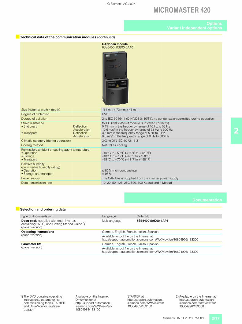
CANopen module6SE6400-1CB00-0AA0
Size (height x width x depth) 161 mm x 73 mm x 46 mmDegree of protection IP20Degree of pollution 2 to IEC 60 664-1 (DIN VDE 0110/T1), no condensation permitted during operationStrain resistance• Stationary
• Transport
DeflectionAccelerationDeflectionAcceleration
to IEC 60 068-2-6 (if module is installed correctly) 0.15 mm in the frequency range of 10 Hz to 58 Hz19.6 m/s2 in the frequency range of 58 Hz to 500 Hz3.5 mm in the frequency range of 5 Hz to 9 Hz9.8 m/s2 in the frequency range of 9 Hz to 500 Hz
Climatic category (during operation) 3K3 to DIN IEC 60 721-3-3Cooling method Natural air coolingPermissible ambient or cooling agent temperature• Operation• Storage• Transport
–10 °C to +50 °C (+14 °F to +122 °F)–40 °C to +70 °C (–40 °F to +158 °F)–25 °C to +70 °C (–13 °F to +158 °F)
Relative humidity(permissible humidity rating)• Operation• Storage and transport
85 % (non-condensing) 95 %
Power supply The CAN bus is supplied from the inverter power supplyData transmission rate 10, 20, 50, 125, 250, 500, 800 Kbaud and 1 Mbaud
Type of documentation Language Order No.Docu pack, supplied with each inverter, containing DVD 1) and Getting Started Guide 2) (paper version)
Multilanguage 6SE6400-5AD00-1AP1
Operating instructions(paper version)
German, English, French, Italian, SpanishAvailable as pdf file on the Internet at http://support.automation.siemens.com/WW/view/en/10804926/133300
Parameter list(paper version)
German, English, French, Italian, SpanishAvailable as pdf file on the Internet at http://support.automation.siemens.com/WW/view/en/10804926/133300
Documentation
1) The DVD contains operating instructions, parameter list, commissioning tools STARTER and DriveMonitor, multilan-guage.
Available on the Internet: DriveMonitor at http://support.automation.siemens.com/WW/view/en/10804984/133100
STARTER at http://support.automation.siemens.com/WW/view/en/10804985/133100
2) Available on the Internet at http://support.automation.siemens.com/WW/view/en/10804926/133300
OptionsVariant independent options
© Siemens AG 2007
2/18 Siemens DA 51.2 · 2007/2008
MICROMASTER 420
2
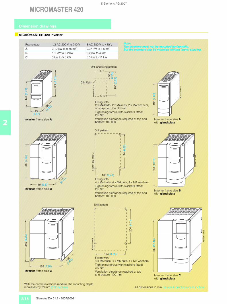
MICROMASTER 420 inverter
With the communications module, the mounting depth increases by 23 mm (0.91 inches).
Frame size 1/3 AC 200 V to 240 V 3 AC 380 V to 480 VA 0.12 kW to 0.75 kW 0.37 kW to 1.5 kWB 1.1 kW to 2.2 kW 2.2 kW to 4 kWC 3 kW to 5.5 kW 5.5 kW to 11 kW
!"
#!!
!" !
#
!
Inverter frame size A
Fixing with 2 x M4 bolts, 2 x M4 nuts, 2 x M4 washers, or snap onto the DIN railTightening torque with washers fitted: 2.5 NmVentilation clearance required at top and bottom: 100 mm
!$
!
Inverter frame size A with gland plate
!
#
!
# "
!# Fixing with 4 x M5 bolts, 4 x M5 nuts, 4 x M5 washersTightening torque with washers fitted: 3.0 NmVentilation clearance required at top and bottom: 100 mm
Inverter frame size C
%
"
Inverter frame size C with gland plate
!#
" #"
!
# !
!
!! Fixing with
4 x M4 bolts, 4 x M4 nuts, 4 x M4 washersTightening torque with washers fitted: 2.5 NmVentilation clearance required at top and bottom: 100 mm
Inverter frame size B
%
Inverter frame size B with gland plate
All dimensions in mm (values in brackets are in inches)
Note: The inverters must not be mounted horizontally. But the inverters can be mounted without lateral spacing.
Dimension drawings
© Siemens AG 2007

Siemens DA 51.2 · 2007/2008 2/19
MICROMASTER 420
2
Filters and chokes
%
"
$
Line commutating choke for
Dimensions Weight (max.)
a b c d e kgFrame size A 200
(7.87)75.5(2.97)
50(1.97)
– – 1.4
Frame size B 213(8.39)
150(5.91)
50(1.97)
220(8.66)
233(9.17)
2.2
Frame size C 245(9.65)
185(7.28)
50(1.97)
264(10.39)
280(11.02)
5.1G_
DA
51
_X
X_
00
06
4
b
a
c
d e
Line commutating choke for frame size A For frame sizes B and C
G_
DA
51
_E
N_
00
06
1
73 (2.87)
56 (2.2)
43.5 (1.71)
20
0(7
.87
)
16
0(6
.3)
18
7(7
.36
)
17
4(6
.85
)2 x M4
G_
DA
51
_E
N_
00
06
2
149 (5.87)
120 (4.72)
50.5 (1.99)
21
3(8
.39
)
17
4(6
.85
)
20
0(7
.87
)
18
7(7
.36
)
4 x M4
138(5.43)
24(0.94)
G_
DA
51
_E
N_
00
06
3
185 (7.28)
156 (6.14)
55 (2.17)
24
5(9
.65
)
20
4(8
.03
)
23
2(9
.13
)
21
9(8
.62
)
4 x M4
174(6.85)
38(1.5)
Filter frame size A For frame size B For frame size C
All dimensions in mm (values in brackets are in inches)
%
#
$
Output choke for frame size A6SE6400-3TC00-4AD26SE6400-3TC00-4AD3
For frame sizes B and C6SE6400-3TC01-0BD36SE6400-3TC03-2CD3
&&
%
$
Output choke type 6SE6400-
Dimensions Weight (max.)
a b c kg3TC00-4AD2 200
(7.87)75.5(2.97)
110(4.33)
1.9
3TC00-4AD3 200(7.87)
75.5(2.97)
50(1.97)
1.3
3TC01-0BD3 213(8.39)
150(5.91)
80(3.15)
4.1
3TC03-2CD3 245(9.65)
185(7.28)
80(3.15)
6.6
Dimension drawings
© Siemens AG 2007

2/20 Siemens DA 51.2 · 2007/2008
MICROMASTER 420
2
LC filter
!
"
!!
#"
""#"
!!
""
"
"#""
LC filter for frame size A LC filter for frame size B
Fixing with M4 bolts Fixing with M4 bolts
!
!"
" #"
#!
All dimensions in mm (values in brackets are in inches)
!
! #
" #
""
"
LC filter for frame size C
Fixing with M5 bolts
"
!#
#
Dimension drawings
© Siemens AG 2007


![MM420 Operating Instructions English [Release A1]MICROMASTER 420 Operating Instructions User Documentation Valid for Release Inverter Type Control Version MICROMASTER 420 September](https://img.pdfslide.net/doc/110x75/613f170ac500cf75ab364da2/mm420-operating-instructions-english-release-a1-micromaster-420-operating-instructions.jpg)