Embed Size (px)
DESCRIPTION
Switch MSAN
Citation preview
ZXMSG 5200AG_BT01_E1
Overview of Soft Switch
Version 1.00
C h a p t e r 1
Data-communication Basics
Key points
Historical background of NGN.
Basic concepts of IP network.
Usual IP voice coding and compression methods
Background story of NGNAs the world is now becoming a small “village”, people, who locate in different places in the earth, can communicate with each other in no time with telephone, email or video etc. The credit of such advantage goes to the development of modern telecommunication technology. Going through the history of the telecommunication will help us to understand the reason and underlying philosophy of all sorts of current techs, and give us the insight of what will happen tomorrow.
PSTN network evolution history
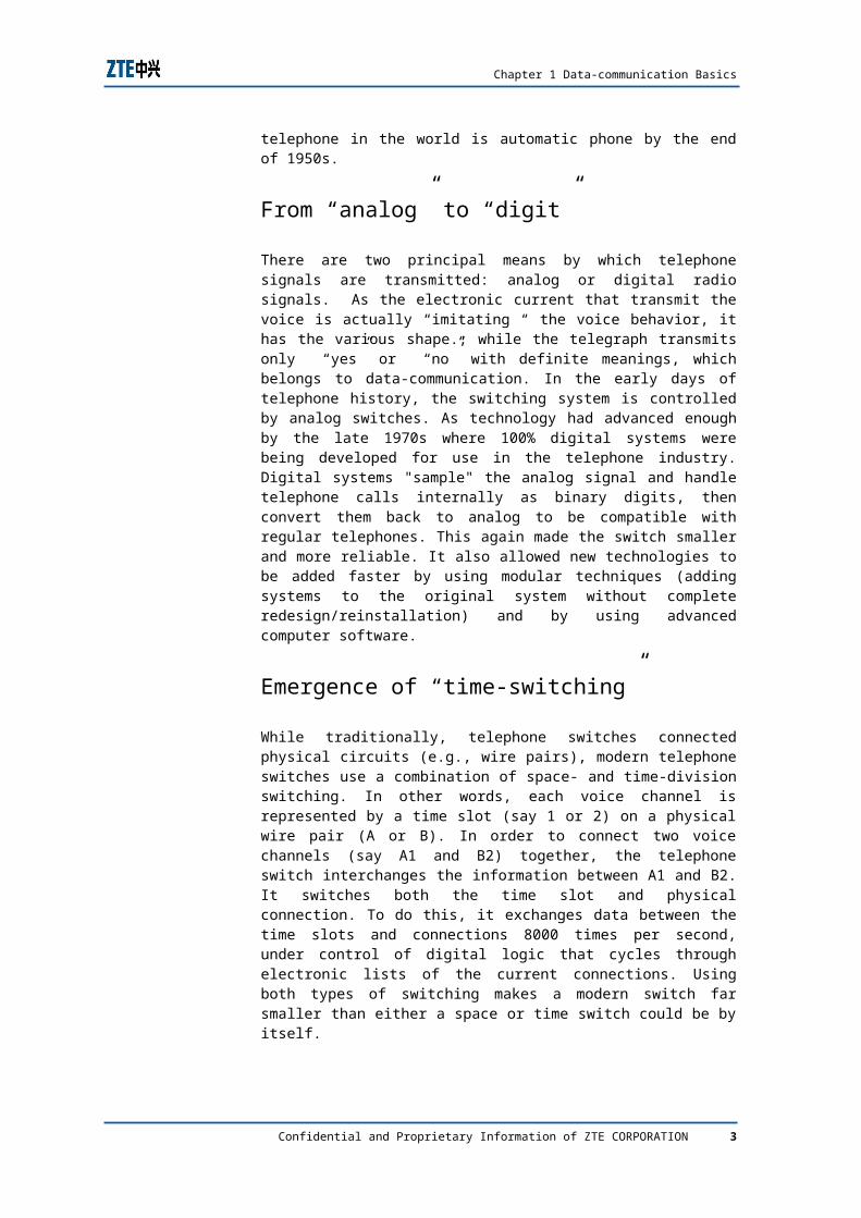
As known to all, Dr. Alexander Graham Bell is the father of telephone, born in 1847, Scotland, 28 year-old Bell braced his invention device with tears while confirming that his device is able to transmit voice. At that night, he wrote to his mother and announced that “the day friends staying at their home can still talk to each other is coming!” During the following long period, telephone business has been supported merely by manual-switching, the experiencing maching-switching and programmed-switching. As shown in Figure 1.
Confidential and Proprietary Information of ZTE CORPORATION 1
Birth of Telephone
F I G U R E 1 T E L E P H O N E H I S T O R Y ( S W I T C H I N G H I S T O R Y )
The first automatic dialing system was patented in 1891 by a Kansas City undertaker who believed that crooked operators were sending his business elsewhere, with his main objective being to eliminate the operators. The first coin telephone was installed in Hartford, Connecticut in 1900. Party lines were soon developed to lower the cost of the telephone for individual families, especially those in rural locations In 1920s, nearly 15% of the telephone in the world is automatic dialing phone, with the development of automatic dialing technology, almost 80% of the telephone in the world is automatic phone by the end of 1950s.
From “analog” to “digit”
There are two principal means by which telephone signals are transmitted: analog or digital radio signals. As the electronic current that transmit the voice is actually “imitating “ the voice behavior, it has the various shape.; while the telegraph transmits only “yes” or “no” with definite meanings, which belongs to data-communication. In the early days of telephone history, the switching system is controlled by analog switches. As technology had advanced enough by the late 1970s where 100% digital systems were being developed for use in the telephone industry. Digital systems "sample" the analog signal and handle telephone calls internally as binary digits, then convert them back to analog to be compatible with regular telephones. This again made the switch smaller and more reliable. It also allowed new technologies to be added faster by using modular techniques (adding systems to the original system without complete redesign/reinstallation) and by using advanced computer software.
Confidential and Proprietary Information of ZTE CORPORATION 2
Chapter 1 Data-communication Basics
Emergence of “time-switching”
While traditionally, telephone switches connected physical circuits (e.g., wire pairs), modern telephone switches use a combination of space- and time-division switching. In other words, each voice channel is represented by a time slot (say 1 or 2) on a physical wire pair (A or B). In order to connect two voice channels (say A1 and B2) together, the telephone switch interchanges the information between A1 and B2. It switches both the time slot and physical connection. To do this, it exchanges data between the time slots and connections 8000 times per second, under control of digital logic that cycles through electronic lists of the current connections. Using both types of switching makes a modern switch far smaller than either a space or time switch could be by itself.
The structure of a switch is an odd number of layers of smaller, simpler subswitches, interconnected by a web of wires that goes from each subswitch, to a set of the next layer of subswitches. In most designs, a physical (space) switching layer will alternate with a time switching layer. The layers are symmetric, because every call is symmetric (there's a connection in both directions).
A space-division subswitch uses digital multiplexers controlled by a cyclic memory. This takes physical space for the wiring.
A time-division subswitch reads a complete cycle of time slots into a memory, and then writes it out in a different order, also under control of a cyclic computer memory. This causes some delay in the signal.
Development of VOIP
Telephone systems have been slowly adopting the "IP" (Internet Protocol) technology over the last decades. Early experiments proved that voice can be converted to digital "packets" and sent over the Internet. The packets would be collected and converted back to analog voice. The quality of the calls was not great but it showed that it could be done. The major problem was something called "packet loss" which is common with TCP/IP connections.
By the early 2000s, the IP telephony (or "VoIP" - Voice over Internet Protocol) technology had improved. Using "classes" of service, reliable connections could be obtained and packet loss reduced to minimum levels. Business systems started using VoIP technology in their PBX (Private Branch Exchange) switches. The telephones themselves were almost like small computers that had their own analog/digital conversion systems and TCP/IP networking technology all the same system. The phone could "piggy-back" on their existing computer network system. Hence having voice AND data traffic over the same wires! As we see the history of VOIP, it can be divided into 3 phases:
Confidential and Proprietary Information of ZTE CORPORATION 3
AG_BT01_E1 Overview of Soft Switch
Phase 1 of the VoIP project: early 1998 to 1 October 1999
This phase was to get the VoIP technology working and to test it in a large pilot between PABXs. During this phase Cisco provided significant support which was to the mutual benefit of Cisco, CSIRO and AARNet. This phase was completed on 1 October 1999.
Key successes of this phase:
VoIP from PABX to PABX became fully functional, as indicated by the testing and major pilot implementations.
The VoIP technology acted as a fully transparent ISDN or Q.Sig network to the PABXs. The Q.Sig included all the advanced PABX features including Call Back, Centralised Operator, Message Waiting indicator, Calling Name Display as well as Calling Number Display.
During the initial setup of a voice call the originating PABX was triggered to route the call to the Public Switched Telephone Network (PSTN) if a problem was encountered in the data network while setting up the call, without either of the users being aware.
A light weight Network Management program was written to stop VoIP during outages, usually on microwave links.
The voice quality was near toll quality.
Facsimile traffic was supported up to 14,400 bits per second, i.e. up to ITU G.3.
A Billing System was written that invoiced the caller and generated MIS reports.
CSIRO had seven Gateways that connected PABXs into the AARNet Voice Service. All Long Distance telephone traffic from CSIRO sites to the major capital cities (not Hobart or Darwin) was sent via AARNet. Calls to the local call area hopped out of AARNet into a CSIRO PABX, which then completed the call by making a Local call into the PSTN.
CSIRO was averaging 3,500 calls per working day with an average call duration of 237 seconds per call, with a 90% saving on call charges (60% of CSIRO calls were between CSIRO sites and thus did not include the Local call charges). Other AARNet Members were likely to achieve savings of 70% to 80%.
Gatekeepers worked and vastly simplified routing tables.
Key caveats of Phase 1:
Modem traffic WAS NOT SUPPORTED, and was not likely to be in the future.
Past generation Video Conference equipment that relied on clear 64kbps ISDN channels WAS NOT SUPPORTED. However the H.323 VoIP technology, which was initially designed to support video, would enable advanced video technology using IP.
4 Confidential and Proprietary Information of ZTE CORPORATION
Chapter 1 Data-communication Basics
Phase 2 of the VoIP Project: 1 October 1999 to 2001
This phase was to roll the technology out to all the AARNet Members and to install Gateways where it was cost effective to do so, that is, there was enough traffic to the local area to warrant the installation of a Gateway. This phase had several parallel components:
Installed Gateways to allow Member telephone traffic to hop out of the AARNet Voice Service at key areas. Initially they were in Canberra, Sydney, Brisbane, Perth, Adelaide and Melbourne.
Selected a Carrier to carry the Local call from the above Gateways into the Public Switch Telephone Network (Last one installed October 2000). Public information about the Tender is available.
Wrote and deployed a Network Monitoring Application AARNet call VoIPMonitor that was scalable to a network the size of AARNet and stopped VoIP over links that were failing.
Assisted AARNet Members to connect to the AARNet Voice Service.
A loose status of the installation of VoIP at each member institution was maintained.
This phase of the roject suffered a massive delay while negotiating a contract with the Carrier for the ISDN connections to connect the AARNet Gateway back into the PSTN (several months). There was also an average 124 day delay waiting for installation (some 3.5 months late).
Phase 3 On-going operation
This phase is the ongoing operational component of the project and includes:
support; and dimensioning the network to carry the traffic.
Projects that may begin where this project ends are:
Video over IP;
User directory services for global roaming; and
User Authentication and Authorization for roaming Voice and Video over IP.
March towards NGN
With the sustainable growth of data services, the current network framework is evolving to Data Networks. Therefore, both the traditional telecom carriers relying mainly on voice services and the emerging Data Network carriers pay much
Confidential and Proprietary Information of ZTE CORPORATION 5
AG_BT01_E1 Overview of Soft Switch
attention to the new-generation Telecom Network that converges voice, video, data and etc. and integrates the PSTN circuit switching with packet switching technology.
The network integration-oriented Soft switch architecture is a total solution of the new-generation multimedia services. It implements the interconnection of various service networks including PSTN/ISDN, PLMN, IN and Internet etc. By optimizing the network architecture, it realizes network integration, and more important, the service integration, thus enabling the inheritance of rich service functions of the traditional Circuit Switching Network, meanwhile providing new services that are hard to be implemented in the traditional networks all over the new-generation network.
Basic concepts of data-communication
OSI Model
The Open Systems Interconnection Reference Model (OSI Model or OSI Reference Model for short) is a layered abstract description for communications and computer network protocol design, developed as part of the Open Systems Interconnect initiative. It is also called the OSI seven layers model.
The OSI model divides the functions of a protocol into a series of layers. Each layer has the property that it only uses the functions of the layer below, and only exports functionality to the layer above. A system that implements protocol behavior consisting of a series of these layers is known as a 'protocol stack' or 'stack'. Protocol stacks can be implemented either in hardware or software, or a mixture of both. Typically, only the lower layers are implemented in hardware, with the higher layers being implemented in software
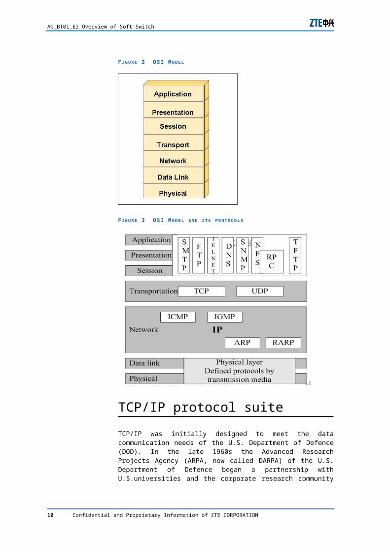
The physical layer defines all electrical and physical specifications for devices. This includes the layout of pins, voltages, and cable specifications. Hubs and repeaters are physical-layer devices.
The data link layer provides the functional and procedural means to transfer data between network entities and to detect and possibly correct errors that may occur in the Physical layer. The addressing scheme is physical which means that the addresses (MAC address) are hard-coded into the network cards at the time of manufacture
The network layer provides the functional and procedural means of transferring variable length data sequences from a source to a destination via one or more networks while maintaining the quality of service requested by the Transport layer. The Network
6 Confidential and Proprietary Information of ZTE CORPORATION
Chapter 1 Data-communication Basics
layer performs network routing, flow control, segmentation/desegmentation, and error control functions. The router operates at this layer -- sending data throughout the extended network and making the Internet possible, although there are layer 3 (or IP) switches. This is a logical addressing scheme - values are chosen by the network engineer. The addressing scheme is hierarchical.
The transport layer provides transparent transfer of data between end users, thus relieving the upper layers from any concern with providing reliable and cost-effective data transfer. The transport layer controls the reliability of a given link. Some protocols are stateful and connection oriented. This means that the transport layer can keep track of the packets and retransmit those that fail. The best known example of a layer 4 protocol is TCP.
The session layer provides the mechanism for managing the dialogue between end-user application processes. It provides for either duplex or half-duplex operation and establishes checkpointing, adjournment, termination, and restart procedures. This layer is responsible for setting up and tearing down TCP/IP sessions.
The presentation layer relieves the Application layer of concern regarding syntactical differences in data representation within the end-user systems. MIME encoding, encryption and similar manipulation of the presentation of data is done at this layer. An example of a presentation service would be the conversion of an EBCDIC-coded text file to an ASCII-coded file.
The application layer interfaces directly to and performs common application services for the application processes. The common application services provide semantic conversion between associated application processes. Examples of common application services include the virtual file, virtual terminal (for example, Telnet), and "Job transfer and Manipulation protocol".
Confidential and Proprietary Information of ZTE CORPORATION 7
AG_BT01_E1 Overview of Soft Switch
F I G U R E 2 OSI M O D E L
F I G U R E 3 OSI M O D E L A N D I T S P R O T O C O L S
TCP/IP protocol suite
TCP/IP was initially designed to meet the data communication needs of the U.S. Department of Defence (DOD). In the late 1960s the Advanced Research Projects Agency (ARPA, now called DARPA) of the U.S. Department of Defence began a partnership with U.S.universities and the corporate research community to design open, standard protocols and build multi-vendor networks.
8 Confidential and Proprietary Information of ZTE CORPORATION
Chapter 1 Data-communication Basics
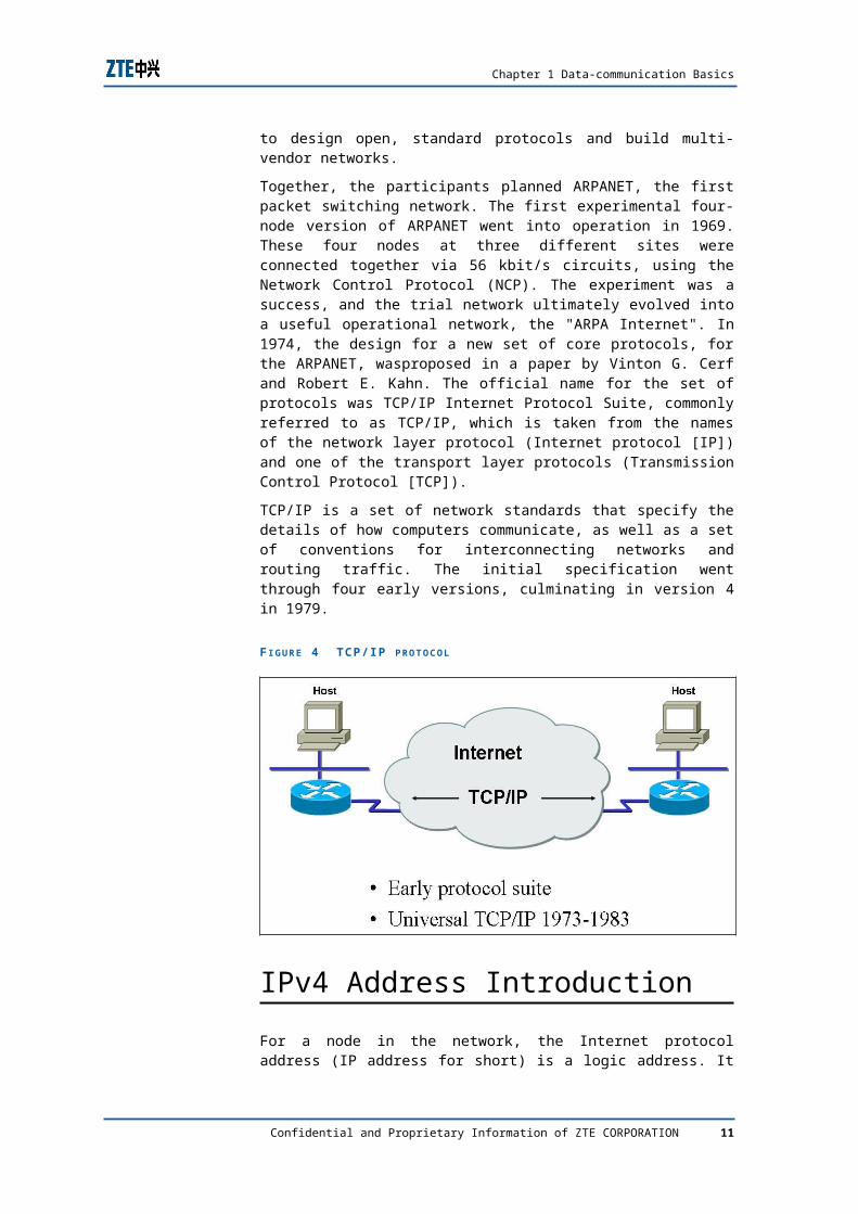
Together, the participants planned ARPANET, the first packet switching network. The first experimental four-node version of ARPANET went into operation in 1969. These four nodes at three different sites were connected together via 56 kbit/s circuits, using the Network Control Protocol (NCP). The experiment was a success, and the trial network ultimately evolved into a useful operational network, the "ARPA Internet". In 1974, the design for a new set of core protocols, for the ARPANET, wasproposed in a paper by Vinton G. Cerf and Robert E. Kahn. The official name for the set of protocols was TCP/IP Internet Protocol Suite, commonly referred to as TCP/IP, which is taken from the names of the network layer protocol (Internet protocol [IP]) and one of the transport layer protocols (Transmission Control Protocol [TCP]).
TCP/IP is a set of network standards that specify the details of how computers communicate, as well as a set of conventions for interconnecting networks and routing traffic. The initial specification went through four early versions, culminating in version 4 in 1979.
F I G U R E 4 TCP/ IP P R O T O C O L
IPv4 Address Introduction
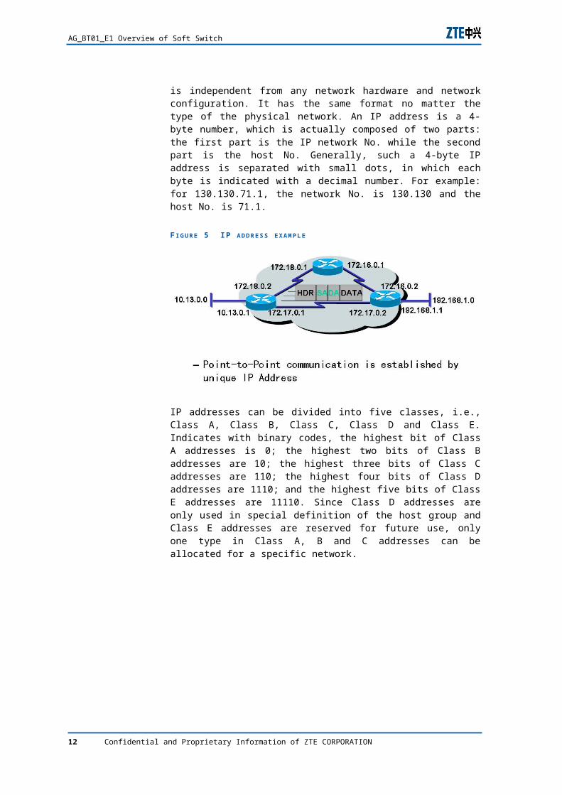
For a node in the network, the Internet protocol address (IP address for short) is a logic address. It is independent from any network hardware and network configuration. It has the same format no matter the type of the physical network. An IP address is a 4-byte number, which is actually composed of two parts: the first part is the IP network No. while the second part is the host No. Generally, such a 4-byte IP address is separated with small dots, in which each byte is indicated with a decimal number. For example: for 130.130.71.1, the network No. is 130.130 and the host No. is 71.1.
Confidential and Proprietary Information of ZTE CORPORATION 9
AG_BT01_E1 Overview of Soft Switch
F I G U R E 5 IP A D D R E S S E X A M P L E
IP addresses can be divided into five classes, i.e., Class A, Class B, Class C, Class D and Class E. Indicates with binary codes, the highest bit of Class A addresses is 0; the highest two bits of Class B addresses are 10; the highest three bits of Class C addresses are 110; the highest four bits of Class D addresses are 1110; and the highest five bits of Class E addresses are 11110. Since Class D addresses are only used in special definition of the host group and Class E addresses are reserved for future use, only one type in Class A, B and C addresses can be allocated for a specific network.
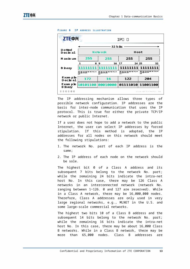
F I G U R E 6 IP A D D R E S S I L L U S T R A T I O N
The IP addressing mechanism allows three types of possible network configuration. IP addresses are the basis for inter-node communication that uses the IP protocol. This is true for either the private TCP/IP network or public Internet.
If a user does not hope to add a network to the public Internet, the user can select IP addresses by forced stipulation. If this method is adopted, the IP addresses for all nodes on this network should meet the following stipulations:
1. The network No. part of each IP address is the same;
10 Confidential and Proprietary Information of ZTE CORPORATION
Chapter 1 Data-communication Basics
2. The IP address of each node on the network should be sole.
The highest bit 0 of a Class A address and its subsequent 7 bits belong to the network No. part; while the remaining 24 bits indicate the intra-net host No. In this case, there may be 126 Class A networks in an interconnected network (network No. ranging between 1~126. 0 and 127 are reserved). While in a Class A network, there may be 16,000,000 nodes. Therefore, Class A addresses are only used in very large regional networks, e.g., MLNET in the U.S. and some large-scale commercial networks.
The highest two bits 10 of a Class B address and the subsequent 14 bits belong to the network No. part; while the remaining 16 bits indicate the intra-net host No. In this case, there may be about 16,000 Class B networks. While in a Class B network, there may be more than 65,000 nodes. Class B addresses are generally used in networks constructed by large institutions and companies.
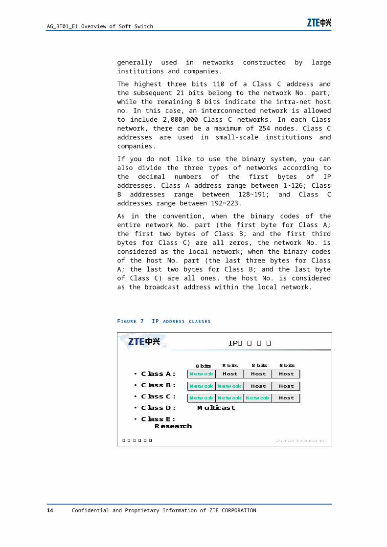
The highest three bits 110 of a Class C address and the subsequent 21 bits belong to the network No. part; while the remaining 8 bits indicate the intra-net host no. In this case, an interconnected network is allowed to include 2,000,000 Class C networks. In each Class network, there can be a maximum of 254 nodes. Class C addresses are used in small-scale institutions and companies.
If you do not like to use the binary system, you can also divide the three types of networks according to the decimal numbers of the first bytes of IP addresses. Class A address range between 1~126; Class B addresses range between 128~191; and Class C addresses range between 192~223.
As in the convention, when the binary codes of the entire network No. part (the first byte for Class A; the first two bytes of Class B; and the first third bytes for Class C) are all zeros, the network No. is considered as the local network; when the binary codes of the host No. part (the last three bytes for Class A; the last two bytes for Class B; and the last byte of Class C) are all ones, the host No. is considered as the broadcast address within the local network.
Confidential and Proprietary Information of ZTE CORPORATION 11
AG_BT01_E1 Overview of Soft Switch
F I G U R E 7 IP A D D R E S S C L A S S E S
Network category
Local Area Networks
Local Area Networks (LANs) accommodate users within a building or on a campus. Ethernet is the leading network technology for LANs or networks contained in buildings or on a single site. Ethernet was first implemented as a shared network using hubs, but high usage caused congestion that could dramatically slow or even shut down the network. Subsequently Ethernet was implemented using a switched architecture scaling performance of the network. The Ethernet ports operated in full duplex, gradually the speed increased form 10 Mbps to 10 Gbps, packet processing at higher layers and routing were added.
Wide-Area Networks and Remote Access
Wide-Area Networks (WANs) connect LANs in campuses across cities, states, and countries. Remote access refers to the connection of an individual user or very small branch office to the central network. A single user can dial up the corporate network directly or gain access via the Internet. Internet Service Providers (ISPs) aggregate multiple users through a router to the campus. In general, LAN speeds are greater than WAN and remote-access speeds. WAN technologies:
1. Dedicated and Dial-Up Access
2. Integrated Services Digital Network (ISDN)
3. Asynchronous Digital Subscriber Line (ADSL)
4. Cable Access
5. Wireless Access
12 Confidential and Proprietary Information of ZTE CORPORATION
Chapter 1 Data-communication Basics
Metropolitan Area Network
Metropolitan Area Networks (MANs) channel traffic within the metro-domain (i.e., inter-business, inter-office, metropolitan connectivity) to and from large long-haul POPS (points of presence). With the successful deployment of many long-haul fiber networks, the focus has shifted towards MANs. The goal is to bring the cost benefits and networks efficiencies of the optical networking to end-users wanting to link campuses with multi-gigabit LANs.
F I G U R E 8 LAN, MAN A N D WAN
Basic concepts of IP telephoneThe transmission of realtime voices via the IP network is different from that of ordinary data. In the former case, the relevant application devices must meet the realtimeness of voices. The voice packet transmission requires the network to provide sufficient bandwidth in time. Therefore, for most of the current IP networks that do not provide so high rates, the voice compression technology is the key for implementing IP voice communication. Now, we will present a brief description of the frequently used voice coding and compression modes at present:
1. PCM
Pulse code modulation (PCM) is the earliest digital voice technology, which does not include any compression algorithm. It transmits voice signals with the 64kbps bandwidth, i.e., taking 8,000 samples per second and
Confidential and Proprietary Information of ZTE CORPORATION 13
AG_BT01_E1 Overview of Soft Switch
acquiring an 8-digit voice signal per sample. PCM is the standard coding mode adopted in G.711.
2. CELP
Code excited linear prediction (CELP) is the most advanced voice transmission technology at present. The CELP algorithm is to compare analog signal samples with curves in the predefined code book; send codes in the code book closest to these analog signal samples to the receiving end; and regenerate original signals after comparison again with the code book at the receiving end. The sampling interval of original signals is very short. Therefore, the regenerated signals are very close to the original signals after being filtered. CELP is the basis of numerous advanced patented voice compression modes. Voices can be compressed to 5.3kbps, 8kbps or 9kbps.
3. CS-ACELP
Conjugate structure algebra code excited linear prediction (CS-ACELP) or G.729 is the 8kbps voice compression and coding standards of International Telecommunications Union (ITU). CS-ACELP is a new algorithm, which is able to encode 8kbps voice signal bit streams (while the rate of ordinary PCM signals is 64kbps). The bandwidth efficiency is eight times as that of PCM and four times as that of 32kbps ADPCM. At present, CS-ACELP is the most welcome voice encoding/decoding plan.
When actually selecting a voice compression algorithm, it is necessary to take various factors into consideration. For example: the pursue of higher bit rates guarantees sound voice quality but requires to occupy more system resources. While lower bit rates will influence voice quality and increase delay. Therefore, to keep better voice quality in the precondition of lower bit rates is the principle for compression algorithm selection.
Given the operational factors that can affect voice quality, how can end-to-end voice quality be assessed? There are several standard methods to measure voice quality. One obvious method, the Mean Opinion Score (MOS or ITU-T P.800) is obtained by conducting a controlled test in which a large number of human listeners make calls to each other and rate the voice quality. Evaluations are derived directly from the individuals who will experience the voice call. MOS is the mean score calculated from this large volume of human opinions (1-5, with 5 being excellent and 4 considered toll quality). Disadvantages of MOS are that it's time-consuming, costly, and inconvenient.
Therefore, voice quality measurement is usually done using one of the following analysis algorithms: Perceptual Speech Quality Measure (PSQM, ITU-T P.861, obsolete), Perceptual Analysis Measurement System (PAMS), or Perceptual Evaluation of Speech (PESQ, ITU-T P.862). These measurements provide the metrics necessary to objectively assess and quantify voice clarity. Most voice-quality test tools provide one or more of these measurements and corresponding MOS estimation for comparison purposes. Though these standards do not reflect the
14 Confidential and Proprietary Information of ZTE CORPORATION
Chapter 1 Data-communication Basics
quality of endpoints, they can be used for quick network assessment. However, even the newest and preferred of these algorithms, PESQ, does not provided a comprehensive evaluation of transmission quality. PESQ measures the effects of one-way speech distortion and noise only, not the effects of two-way interaction such as loudness, delay, and echo. A network can have a high PESQ score and yet have poor connection quality. Most importantly, these measurement methods do not provide enough analytical information about where in the network problems might occur.
Network infrastructure components (PSTN trunks or lines, voice gateways, analog and IP phones, etc.) affect voice quality by creating a loss insertion. Therefore, in the network planning or revising stage a comprehensive voice-quality analysis--a transmission loss and level plan--needs to be performed for the entire network. The design needs to be optimized to the desired level of voice quality between any two users of the private network as well as between the network and other--usually, public--networks.
Homework1. Please briefly discuss the telephone history
2. What are the common decoding/encoding algorithm in telephone history, describe the differences
Confidential and Proprietary Information of ZTE CORPORATION 15
C h a p t e r 2
NGN Architecture
Key points
The next generation network architecture based on softswitch technology.
ZTE softswitch product series.
NGN network protocol family.
Why NGNAt present, two totally independent networks exist: the PSTN network and data network, which provide the voice service and basic data service respectively.
Network separation and isolation of operation & maintenance have been keeping the general network operation & maintenance costs on a high level, and furthermore, a network cannot provide complicated convergence services, although the network convergence has been an inevitable trend.
Since a traditional voice network is a closed network with monopolized resources, it has become a common understanding in the telecom industry that the packet network (typically, the Internet), with the advantages such as open architecture, low costs and large scale, will replace the PSTN to become the basic frame of the next generation of convergence networks and that the construction of the next generation of networks will be based on current packet networks.
It is necessary for carriers to consider resource utilization and investment protection during construction of future networks. On one hand, carriers should trace the latest technologies; and on the other hand, they should try to utilize existing technologies and resources. Thus, carriers can provide users with large numbers of services economically and rapidly to make the highest profits, without the need of large-scale network alteration.
The solution of smooth transition from existing networks to the next generation networks is the key to the problem. The
Confidential and Proprietary Information of ZTE CORPORATION 17
Softswitch solution based on softswitch technology is just a mainstream solution to smooth network evolution
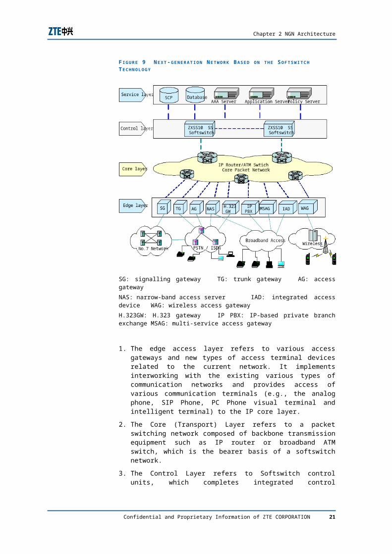
ZTE NGN Softsiwtch ArchitecutureHierarchical models are adopted for the Softswitch-based next generation network. The entire network can be divided into four layers: Service Layer, Control Layer, Core (Transport) Layer and Edge Access Layer, as shown in Figure 9.
F I G U R E 9 N E X T -G E N E R A T I O N N E T W O R K B A S E D O N T H E S O F T S W I T C H T E C H N O L O G Y
SG: signalling gateway TG: trunk gateway AG: access gateway
NAS: narrow-band access server IAD: integrated access device WAG: wireless access gateway
H.323GW: H.323 gateway IP PBX: IP-based private branch exchange MSAG: multi-service access gateway
1. The edge access layer refers to various access gateways and new types of access terminal devices related to the current network. It implements interworking with the existing various types of communication networks and provides access of various communication terminals (e.g., the analog phone, SIP
Confidential and Proprietary Information of ZTE CORPORATION 18
Chapter 2 NGN Architecture
Phone, PC Phone visual terminal and intelligent terminal) to the IP core layer.
2. The Core (Transport) Layer refers to a packet switching network composed of backbone transmission equipment such as IP router or broadband ATM switch, which is the bearer basis of a softswitch network.
3. The Control Layer refers to Softswitch control units, which completes integrated control processing functions such as call processing control, access protocol adaptation, interconnection and interworking and provides an application support platform for the entire network.
4. The Application Layer provides a network with various applications and services, client-oriented integrated intelligent services and service customization.
Where, standard interfaces are used for communication between layers. Under the control of the core equipment (i.e., the Softswitch control equipment) and based on division of labor and cooperation of work, the related NE equipment implements various service functions of the system.
In softswitch architecture, the softswitch control equipment is the core, which is independent of the bottom-layer bearer protocols and implements functions such as call control media gateway access control, resource allocation, protocol processing, routing, authentication and accounting. The softswitch control equipment can provide all basic call services, supplementary services and point-to-point multimedia services a PSTN can provide. Furthermore, with the cooperation of the Service Layer equipment (SCP) and Application Server, the equipment also can provide users with traditional intelligent services, value-added IP services, diverse third-party value added services and new intelligent services.
ZTE Softswtich
ZXSS10 SS1a is a piece of softswitch control equipment with medium capacity, which can process hundreds of thousands of calls. ZXSS10 SS1b is a piece of softswitch control equipment with large capacity, which can process millions of calls.
ZXSS10 SS1A/B: softswitch core control device
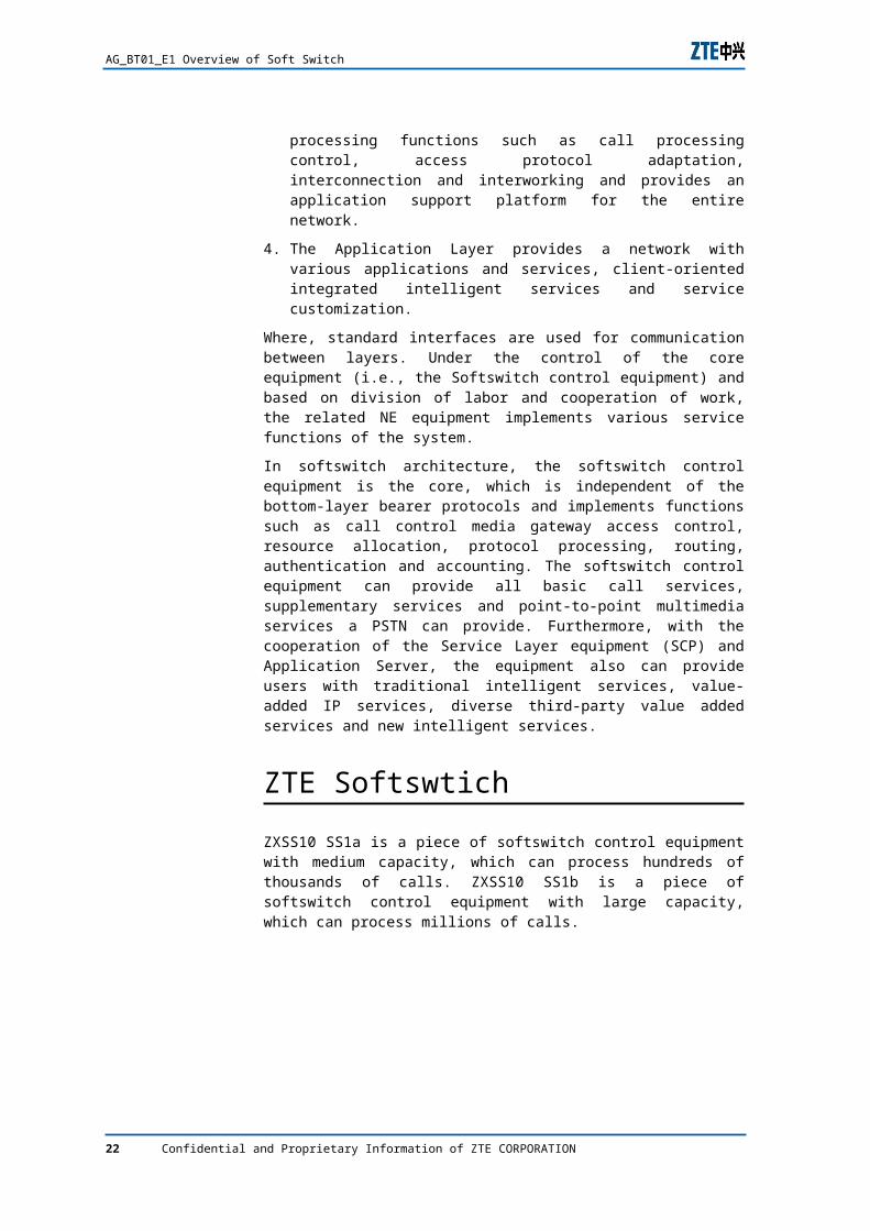
The ZXSS10 SS1a shelf is 19-inch wide and 4U high. The boards in the shelf are mounted in the front / rear face-to-face mode. Therefore, the interface boards with cables can be mounted from the back, preventing cabling in the front. The integrated shelf is composed of a standard and integrated shelf, a PCB and a power box. It provides six slots for horizontally-mounted boards. The
Confidential and Proprietary Information of ZTE CORPORATION 19

AG_BT01_E1 Overview of Soft Switch
backplane which is 3.2 mm deep can accommodate twelve boards mounted in the front / rear face-to-face mode. Figure10 is the front view of the ZXSS10 SS1a shelf.
F I G U R E 10 F R O N T V I E W O F T H E ZXSS10 SS1 A (4U)
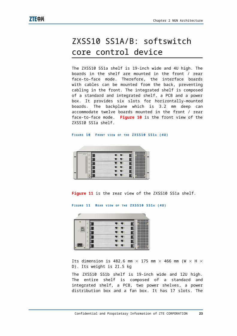
Figure 11 is the rear view of the ZXSS10 SS1a shelf.
F I G U R E 11 R E A R V I E W O F T H E ZXSS10 SS1 A (4U)
Its dimension is 482.6 mm 175 mm 466 mm (W H D). Its weight is 21.5 kg
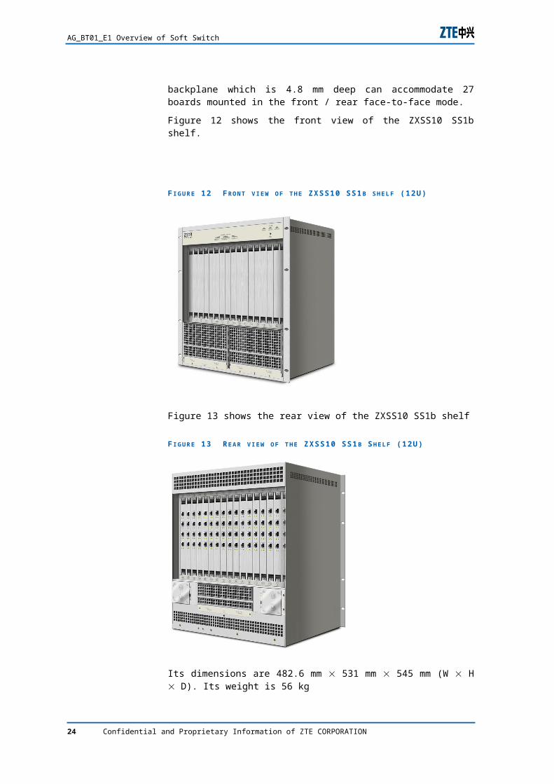
The ZXSS10 SS1b shelf is 19-inch wide and 12U high. The entire shelf is composed of a standard and integrated shelf, a PCB, two power shelves, a power distribution box and a fan box. It has 17 slots. The backplane which is 4.8 mm deep can accommodate 27 boards mounted in the front / rear face-to-face mode.
Figure 12 shows the front view of the ZXSS10 SS1b shelf.
20 Confidential and Proprietary Information of ZTE CORPORATION
Chapter 2 NGN Architecture
F I G U R E 12 F R O N T V I E W O F T H E ZXSS10 SS1 B S H E L F (12U)
Figure 13 shows the rear view of the ZXSS10 SS1b shelf
F I G U R E 13 R E A R V I E W O F T H E ZXSS10 SS1 B S H E L F (12U)
Its dimensions are 482.6 mm 531 mm 545 mm (W H D). Its weight is 56 kg
ZXMSG 7200: integrated media gateway
In addition to the channel associated signaling and DSS1 signaling processing functions, the ZXMSG 7200 provides the trunk media gateway, access media gateway, Media-Server and
Confidential and Proprietary Information of ZTE CORPORATION 21
AG_BT01_E1 Overview of Soft Switch
SS7 gateway functions. These functions can be applied separately on the ZXMSG 7200 or combined with other functions as an integrated media gateway. The ZXMSG 7200 provides the hairpin function between TDM interfaces, and the equipment can be used as the PSTN/PLMN tandem or toll office.
The ZXMSG 7200 No.7 signaling system is developed strictly in accordance with the relevant standard and ITU-T recommendation, fully implementing the SS7 MTP2, MTP3 and SCCP and other functions and realizing such protocols as the SCTP, M3UA and M2PA of the SIGTRAN protocol stack. In addition, it features the powerful processing capability, high reliability and complete maintenance function, and can work in the SG proxy mode or the SG signaling transfer mode. When the ZXMSG 7200 functions as an SG, the GS works as the built-in signaling gateway of the media gateway. If the required signaling processing capability is stronger, it is recommended to configure the dedicated independent signaling gateway.
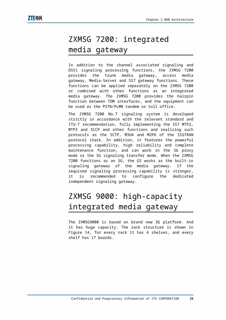
ZXMSG 9000: high-capacity integrated media gateway
The ZXMSG9000 is based on brand new 3G platform. And it has huge capacity. The rack structure is shown in Figure 14, for every rack it has 4 shelves, and every shelf has 17 boards.
F I G U R E 14 ZXMSG9000 R A C K S T R U C T U R E
22 Confidential and Proprietary Information of ZTE CORPORATION
Chapter 2 NGN Architecture
ZXMSG 5200: multi-service access gateway
The ZXMSG 5200 is applied in the edge access layer of the NGN network. It can provide abundant services for various users. For ordinary users, it can perform many services such as Video On Demand (VOD), online stock purchasing, online teaching, tele-medicine and cell network administration. After commissioning the IPTV service in later period, it can provide more abundant video service for users. For corp subscribers such as enterprises, banks, governments, hotels and schools, it provides more service types including complex dedicated line service besides voice and data service access. So the demand of access mode is also various. For low speed dedicated line service, it can provide narrowband data dedicated lines such as subrate, 64k, N*64k, 2M by ZXMSG 5200. For broadband dedicated line demand, it can provide the access of dedicated data service such as :LAN,ADSL,G SHDSL and VDSL conveniently.
ZXSS10 A200: Access Gateway
A200 (ZXSS10 A200 access gateway) connects analog telephone subscriber to SOFTSWITCH network and can provide V5 subscriber access and some data services. Combining with DSLAM, it also can provide subscribers with broadband data access.
AG can be placed in cells and buildings to replace the end office in PSTN network. It is flexible to use and convenient to network, and can be maintained and managed uniformly.
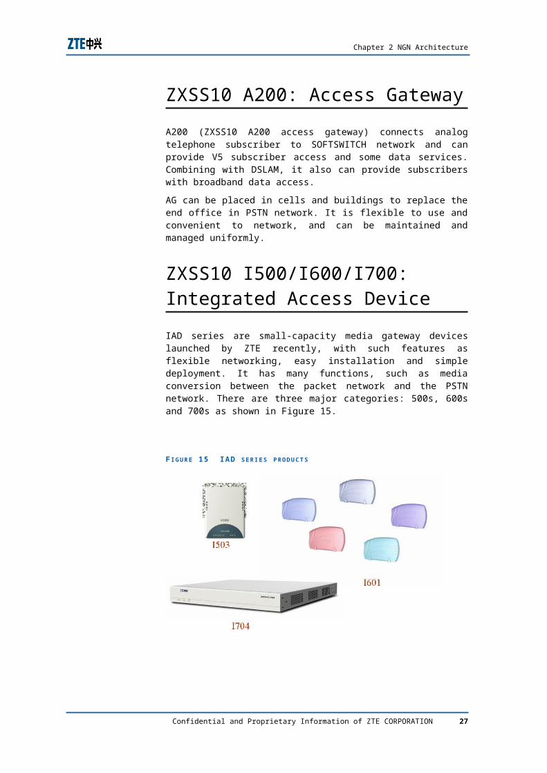
ZXSS10 I500/I600/I700: Integrated Access Device
IAD series are small-capacity media gateway devices launched by ZTE recently, with such features as flexible networking, easy installation and simple deployment. It has many functions, such as media conversion between the packet network and the PSTN network. There are three major categories: 500s, 600s and 700s as shown in Figure 15.
Confidential and Proprietary Information of ZTE CORPORATION 23
AG_BT01_E1 Overview of Soft Switch
F I G U R E 15 IAD S E R I E S P R O D U C T S
ZXSS10 B100: Broad-band gateway
The ZXSS10 B100 provides the following functions:
Supporting network address translation (NAT) of H.248 / MGCP / SIP protocols.
Supporting NAT traversal
Supporting dynamic user registration.
Supporting the backup calling agency.
Providing command line interfaces (based on Telnet and serial port).
Supporting remote FTP version upgrade
Supporting bandwidth-based strategy control.
Supporting a hidden network topology.
NGN network protocolsZXSS10 SS1A/B core control device is a protocol entity, depending on several protocols, to enable the inter-communicating with various networks. It is a high-compatible solution to deal with the future breakthrough of a new technology. Once there is a new tech, all it needs is upgrading the software version and provide associated devices in access layer, the hardware structure of the system could still remain intact.
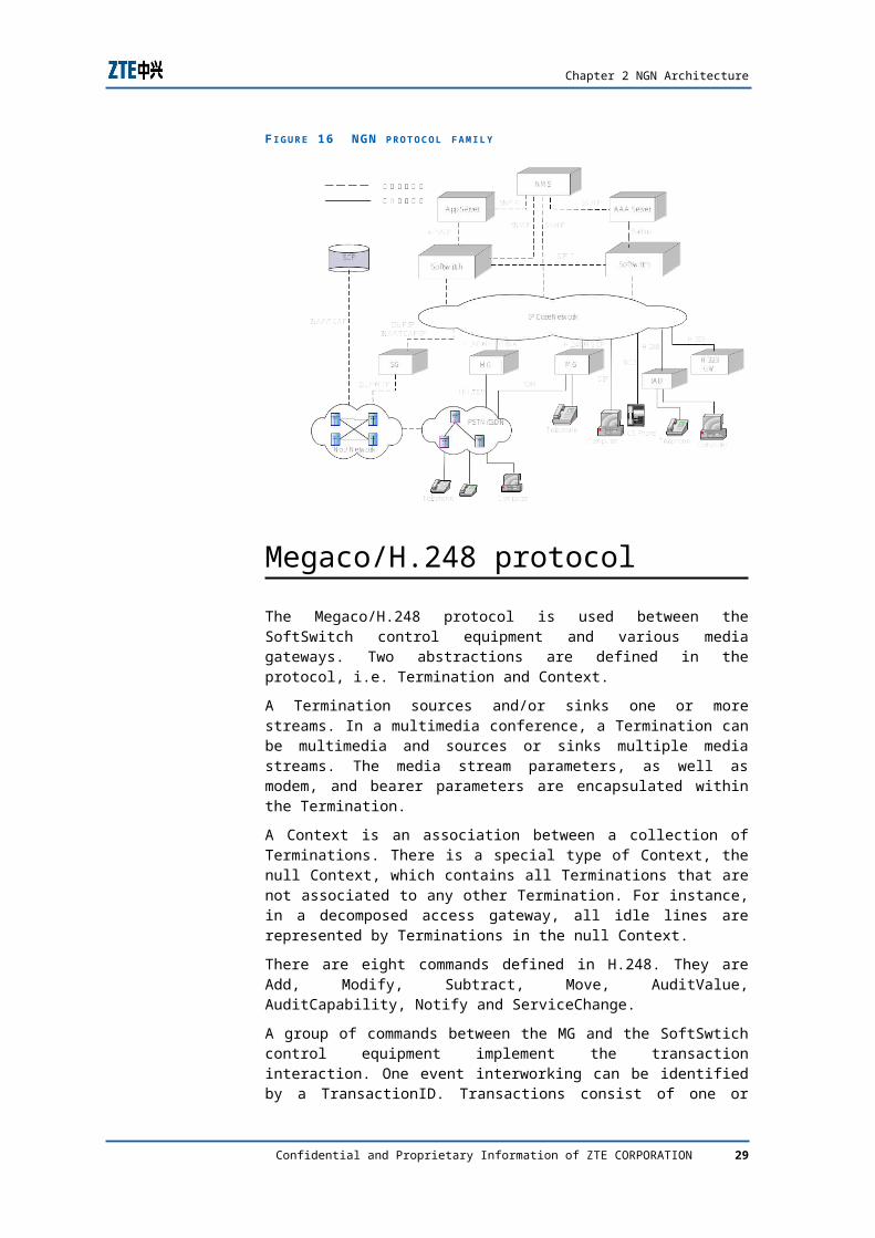
Generally, ZXSS10 SS1A/B supports the standard protocols include: MGCP, MEGACO/H.248, SIP, ISUP/TUP, SNMP, M3UA, SCTP, H.323, etc. The protocol system is illustrated in Figure 16.
24 Confidential and Proprietary Information of ZTE CORPORATION
Chapter 2 NGN Architecture
F I G U R E 16 NGN P R O T O C O L F A M I L Y
Megaco/H.248 protocol
The Megaco/H.248 protocol is used between the SoftSwitch control equipment and various media gateways. Two abstractions are defined in the protocol, i.e. Termination and Context.
A Termination sources and/or sinks one or more streams. In a multimedia conference, a Termination can be multimedia and sources or sinks multiple media streams. The media stream parameters, as well as modem, and bearer parameters are encapsulated within the Termination.
A Context is an association between a collection of Terminations. There is a special type of Context, the null Context, which contains all Terminations that are not associated to any other Termination. For instance, in a decomposed access gateway, all idle lines are represented by Terminations in the null Context.
There are eight commands defined in H.248. They are Add, Modify, Subtract, Move, AuditValue, AuditCapability, Notify and ServiceChange.
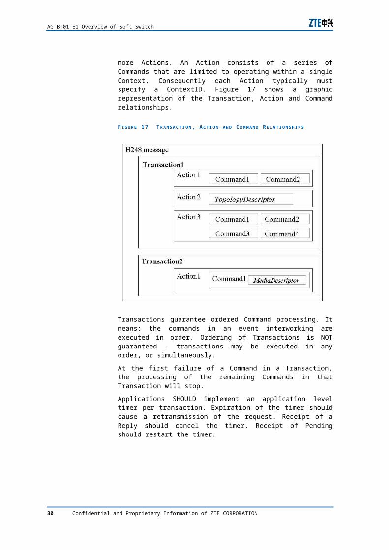
A group of commands between the MG and the SoftSwtich control equipment implement the transaction interaction. One event interworking can be identified by a TransactionID. Transactions consist of one or more Actions. An Action consists of a series of Commands that are limited to operating within a single Context. Consequently each Action typically must specify a ContextID. Figure 17 shows a graphic representation of the Transaction, Action and Command relationships.
Confidential and Proprietary Information of ZTE CORPORATION 25
AG_BT01_E1 Overview of Soft Switch
F I G U R E 17 T R A N S A C T I O N , A C T I O N A N D C O M M A N D R E L A T I O N S H I P S
Transactions guarantee ordered Command processing. It means: the commands in an event interworking are executed in order. Ordering of Transactions is NOT guaranteed - transactions may be executed in any order, or simultaneously.
At the first failure of a Command in a Transaction, the processing of the remaining Commands in that Transaction will stop.
Applications SHOULD implement an application level timer per transaction. Expiration of the timer should cause a retransmission of the request. Receipt of a Reply should cancel the timer. Receipt of Pending should restart the timer.
SIGTRAN protocol
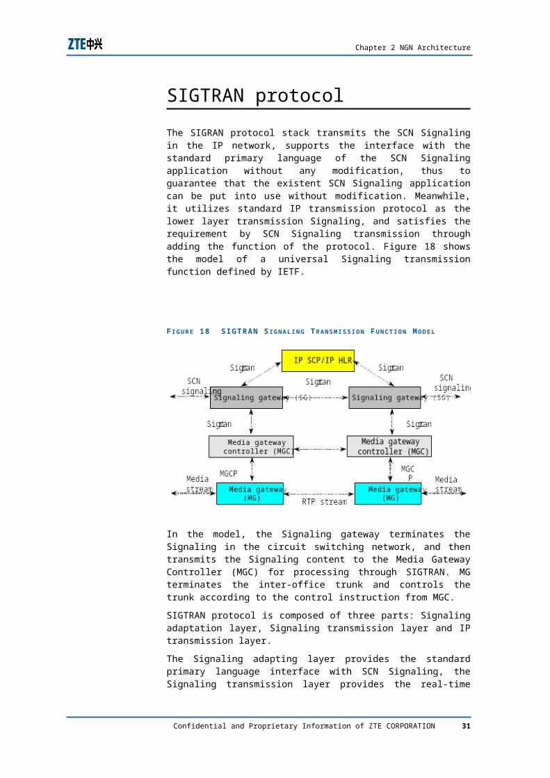
The SIGRAN protocol stack transmits the SCN Signaling in the IP network, supports the interface with the standard primary language of the SCN Signaling application without any modification, thus to guarantee that the existent SCN Signaling application can be put into use without modification. Meanwhile, it utilizes standard IP transmission protocol as the lower layer transmission Signaling, and satisfies the requirement by SCN Signaling transmission through adding the function of the protocol. Figure 18 shows the model of a universal Signaling transmission function defined by IETF.
26 Confidential and Proprietary Information of ZTE CORPORATION
Chapter 2 NGN Architecture
F I G U R E 18 S IGTRAN S I G N A L I N G T R A N S M I S S I O N F U N C T I O N M O D E L
In the model, the Signaling gateway terminates the Signaling in the circuit switching network, and then transmits the Signaling content to the Media Gateway Controller (MGC) for processing through SIGTRAN. MG terminates the inter-office trunk and controls the trunk according to the control instruction from MGC.
SIGTRAN protocol is composed of three parts: Signaling adaptation layer, Signaling transmission layer and IP transmission layer.
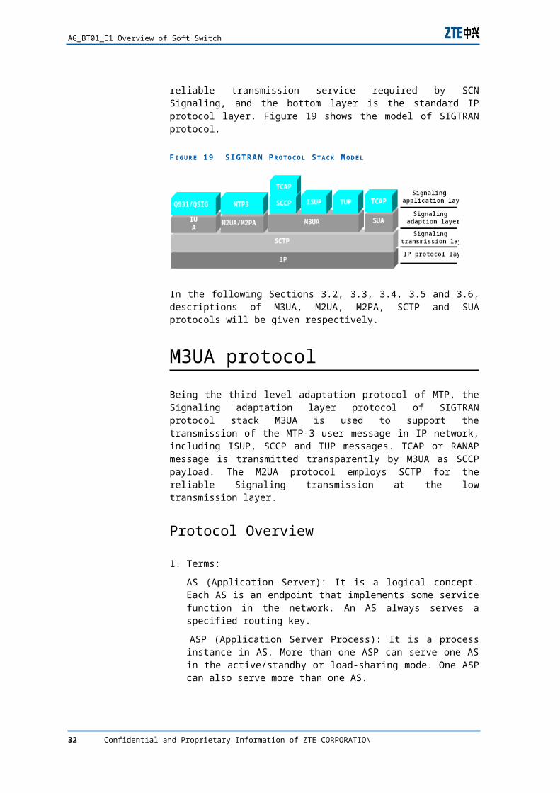
The Signaling adapting layer provides the standard primary language interface with SCN Signaling, the Signaling transmission layer provides the real-time reliable transmission service required by SCN Signaling, and the bottom layer is the standard IP protocol layer. Figure 19 shows the model of SIGTRAN protocol.
F I G U R E 19 S IGTRAN P R O T O C O L S T A C K M O D E L
In the following Sections 3.2, 3.3, 3.4, 3.5 and 3.6, descriptions of M3UA, M2UA, M2PA, SCTP and SUA protocols will be given respectively.
Confidential and Proprietary Information of ZTE CORPORATION 27
AG_BT01_E1 Overview of Soft Switch
M3UA protocol
Being the third level adaptation protocol of MTP, the Signaling adaptation layer protocol of SIGTRAN protocol stack M3UA is used to support the transmission of the MTP-3 user message in IP network, including ISUP, SCCP and TUP messages. TCAP or RANAP message is transmitted transparently by M3UA as SCCP payload. The M2UA protocol employs SCTP for the reliable Signaling transmission at the low transmission layer.
Protocol Overview
1. Terms:
AS (Application Server): It is a logical concept. Each AS is an endpoint that implements some service function in the network. An AS always serves a specified routing key.
ASP (Application Server Process): It is a process instance in AS. More than one ASP can serve one AS in the active/standby or load-sharing mode. One ASP can also serve more than one AS.
SCTP connection: It provides the service of transmitting MTP3 user Signaling protocol data and the message between peer layers of M3UA.
Routing key: Each routing key in the gateway defines a collection of routing characteristics of SS7 Signaling message. The SS7 Signaling message with the required characteristics is processed by a designated AS.
Routing Context: These are parameter values of ASPM message between gateway and ASP. The parameter uniquely identifies the SS7 Signaling message related to a specific AS, that is to say, the message keeps a one-to-one relationship with the routing key or AS.
2. Signaling Transmission Model
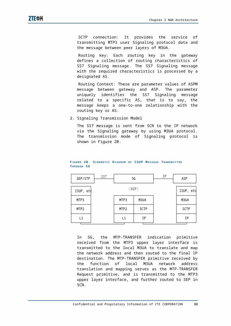
The SS7 message is sent from SCN to the IP network via the Signaling gateway by using M3UA protocol. The transmission mode of Signaling protocol is shown in Figure 20.
28 Confidential and Proprietary Information of ZTE CORPORATION
Chapter 2 NGN Architecture
F I G U R E 20 S C H E M A T I C D I A G R A M O F ISUP M E S S A G E T R A N S M I T T E D T H R O U G H SG
In SG, the MTP-TRANSFER indication primitive received from the MTP3 upper layer interface is transmitted to the local M3UA to translate and map the network address and then routed to the final IP destination. The MTP-TRANSFER primitive received by the function of local M3UA network address translation and mapping serves as the MTP-TRANSFER Request primitive, and is transmitted to the MTP3 upper layer interface, and further routed to SEP in SCN.
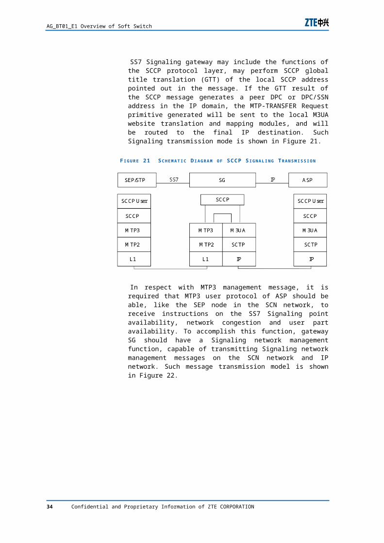
SS7 Signaling gateway may include the functions of the SCCP protocol layer, may perform SCCP global title translation (GTT) of the local SCCP address pointed out in the message. If the GTT result of the SCCP message generates a peer DPC or DPC/SSN address in the IP domain, the MTP-TRANSFER Request primitive generated will be sent to the local M3UA website translation and mapping modules, and will be routed to the final IP destination. Such Signaling transmission mode is shown in Figure 21.
F I G U R E 21 S C H E M A T I C D I A G R A M O F SCCP S I G N A L I N G T R A N S M I S S I O N
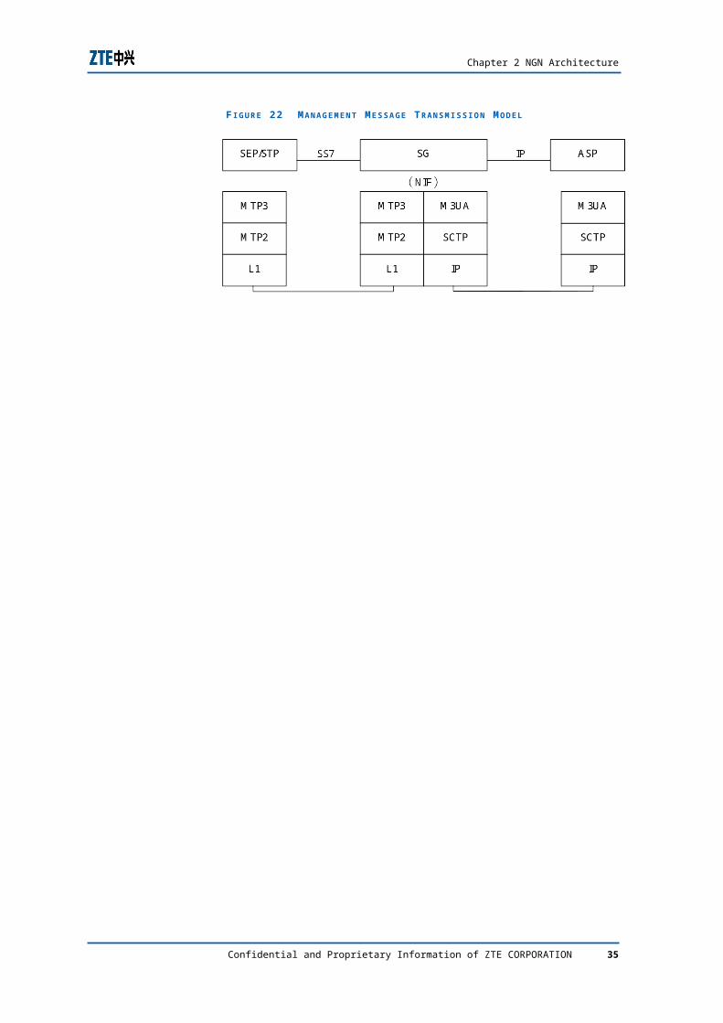
In respect with MTP3 management message, it is required that MTP3 user protocol of ASP should be able, like the SEP node in the SCN network, to receive instructions on the SS7 Signaling point availability, network congestion and user part
Confidential and Proprietary Information of ZTE CORPORATION 29
AG_BT01_E1 Overview of Soft Switch
availability. To accomplish this function, gateway SG should have a Signaling network management function, capable of transmitting Signaling network management messages on the SCN network and IP network. Such message transmission model is shown in Figure 22.
F I G U R E 22 MA N A G E M E N T M E S S A G E T R A N S M I S S I O N M O D E L
30 Confidential and Proprietary Information of ZTE CORPORATION
C h a p t e r 3
ZTE NGN Solution
Key points
Key problems in softswitch deployment and their solution.
ZTE softswitch network solutions.
New services supported by ZTE softswitch system.
Key problems in softswitch deployment
Addressing
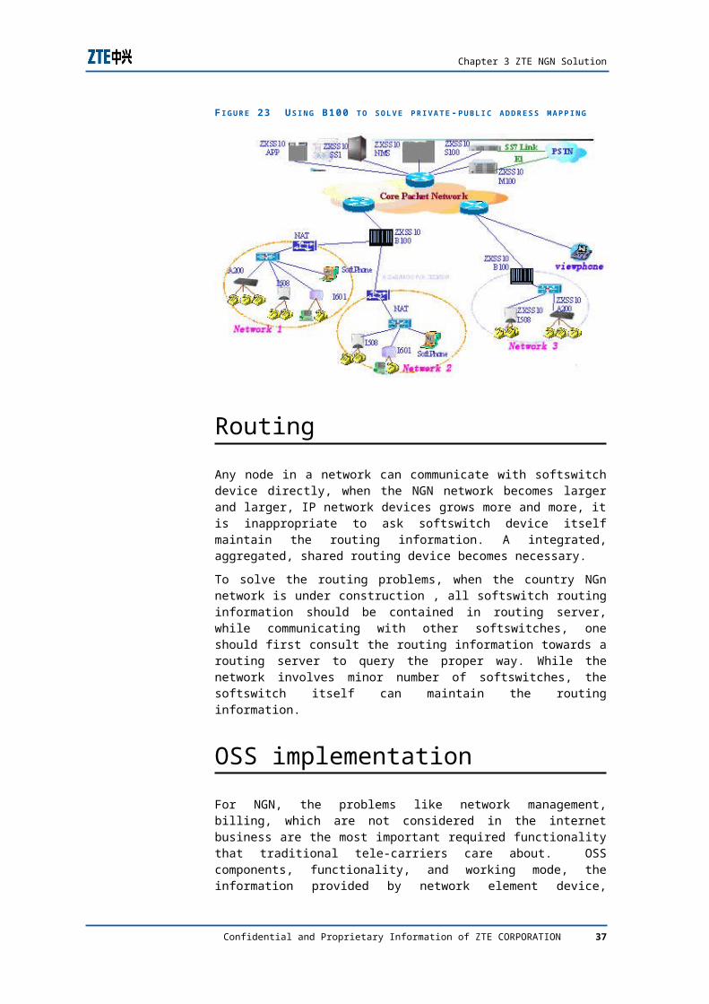
As a node in package-switching network, softswitch device must have its own network identifier, in IP network, which is IP address. However, the identifier normally is limited and can not be assigned randomly. As the development of NGN network and user scale becoming bigger and bigger, the number of identifiers (IPv4 addresses) will not be enough. To solve this problem is to user private identifier, which rises another problem – mapping from private identifier to public identifier. ZXSS10 BGW device is designed to solve such problems.
Confidential and Proprietary Information of ZTE CORPORATION 31
AG_BT01_E1 Overview of Soft Switch
F I G U R E 23 U S I N G B100 T O S O L V E P R I V A T E -P U B L I C A D D R E S S M A P P I N G
Routing
Any node in a network can communicate with softswitch device directly, when the NGN network becomes larger and larger, IP network devices grows more and more, it is inappropriate to ask softswitch device itself maintain the routing information. A integrated, aggregated, shared routing device becomes necessary.
To solve the routing problems, when the country NGn network is under construction , all softswitch routing information should be contained in routing server, while communicating with other softswitches, one should first consult the routing information towards a routing server to query the proper way. While the network involves minor number of softswitches, the softswitch itself can maintain the routing information.
OSS implementation
For NGN, the problems like network management, billing, which are not considered in the internet business are the most important required functionality that traditional tele-carriers care about. OSS components, functionality, and working mode, the information provided by network element device, interfaces between OSS and application system, inter-working and implementation with existing network management system, billing system, and authentication system are also very important problems which need to be solved in recent years. ZTE softswitch EMS system partially solved the above problems and provided a unified network management system EMS.
32 Confidential and Proprietary Information of ZTE CORPORATION
Chapter 3 ZTE NGN Solution
QoS
From the policies below, it is clear that the ZTE softswitch system can not only ensure the voice forwarding with highest priority but also control the bandwidth and traffic of voice and video services in the network to ensure the QoS of voice and video services, providing subscribers with carrier-class QoS.
Design and Construct Appropriate Network Bandwidth to Meet the Requirements of Ensuring QoS
Appropriate bandwidth is an important means to ensure QoS. For instance, a comparatively clear IP telephone will seize a network bandwidth of 12 kbps. As a result, it is impossible for a 64 kbps link to bear 8 such IP telephones simultaneously. In addition, the delay of data transmission in the entire network will be decreased in a certain range with the increase of physical line bandwidth.
A basic design conception is: To select line bandwidth according to the services that seized large bandwidth; to consider services’ multiplexing the bandwidth according to the application frequency of service. But if the services in the network are all frequent services, only overlapping bandwidth can be employed. It is a must to take the actual condition of carrier’s network bandwidth resource into consideration to analyze when using the line in practice.
The tandem layer and backbone layer of the entire network employ the modes of service differentiating and priority queuing to ensure the QoS of voice and video
For the network that VPN can be partitioned, it is recommended that the services of voice and video should be attached to a VPN, differentiating from data service, consequently the QoS and network security of voice and video can be ensured.
If VPN cannot be partitioned, it is recommended to classify the services and forward packet according to the priority. Configure the voice and video services with higher priority than data service to ensure that the services of voice and video be forwarded prior to data service, as a result, avoid the impact on voice and video services originated by masses of burst data service.
Confidential and Proprietary Information of ZTE CORPORATION 33
AG_BT01_E1 Overview of Soft Switch
QoS Warranty Policy for LAN Access Subscribers.
The LAN Access Subscribers Can be Classified as Two Categories:
The CPN transmission equipment does not support Vlan partition.
Assign the voice/video service terminal and Internet service terminal to different Ethernets, isolated physically. The IP address partition of voice/video service terminal and Internet service terminal is in different network segments.
The CPN transmission equipment supports Vlan partition.
Unify the service planning in the CPN: Partition different services into different VLANs, for instance, unify the voice service terminal into VLAN1, video service terminal into VLAN2, and Internet service terminal into VLAN3. Consequently, the switch can reorder the priority of service forwarding according to VLAN numbers, forward real-time service with high priority to ensure QoS.
The QoS Mechanism of ZTE Softswitch System Equipment
1. The subscriber terminal IAD supports 802.1P two queues priority.
2. IAD supports 802.1Q VLAN technology and 802.1Q VLAN TAG, partitions voice from data service at the fringe of access.
3. All IADs and media gateways of ZTE softswitch support technologies including echo-offset and delay jittering.
4. The media gateway can acquire the transmission condition of related voice media stream, and reports to core control device of softswitch, which control the subscriber calling access in accordance with the traffic of subscribers in the media gateway.
5. The broadband gateway can implement NAT between public and private network and control subscriber access according to the number of accessed terminal subscribers to control the traffic of the CPN subscribers.
ZTE softswitch network solutionZTE Softswitch can be used in many different networking scenarios.
34 Confidential and Proprietary Information of ZTE CORPORATION
Chapter 3 ZTE NGN Solution
Class 4 Replacement
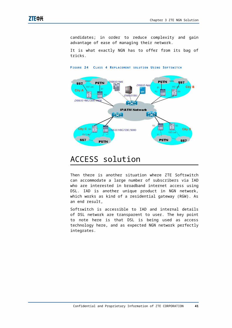
Class 4 replacement is more popular among incumbent carriers as they are not keen in replacing C5 switches in near future. C4 switches however, if at all replaced, are prime choice of carriers as replacement candidates; in order to reduce complexity and gain advantage of ease of managing their network.
It is what exactly NGN has to offer from its bag of tricks.
F I G U R E 24 C L A S S 4 R E P L A C E M E N T S O L U T I O N U S I N G S O F T S W I T C H
ACCESS solution
Then there is another situation where ZTE Softswitch can accommodate a large number of subscribers via IAD who are interested in broadband internet access using DSL. IAD is another unique product in NGN network, which works as kind of a residential gateway (RGW). As an end result,
Softswitch is accessible to IAD and internal details of DSL network are transparent to user. The key point to note here is that DSL is being used as access technology here, and as expected NGN network perfectly integrates.
Confidential and Proprietary Information of ZTE CORPORATION 35
AG_BT01_E1 Overview of Soft Switch
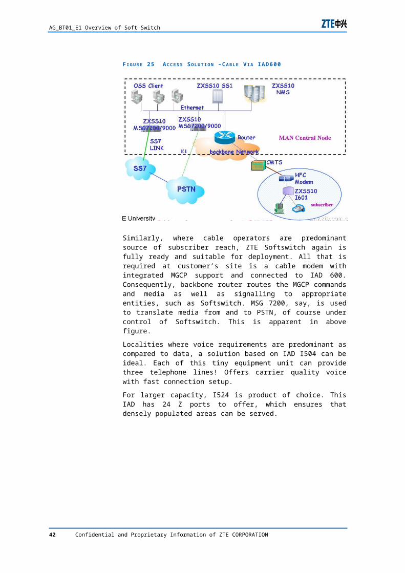
F I G U R E 25 A C C E S S S O L U T I O N –C A B L E V I A IAD600
Similarly, where cable operators are predominant source of subscriber reach, ZTE Softswitch again is fully ready and suitable for deployment. All that is required at customer’s site is a cable modem with integrated MGCP support and connected to IAD 600. Consequently, backbone router routes the MGCP commands and media as well as signalling to appropriate entities, such as Softswitch. MSG 7200, say, is used to translate media from and to PSTN, of course under control of Softswitch. This is apparent in above figure.
Localities where voice requirements are predominant as compared to data, a solution based on IAD I504 can be ideal. Each of this tiny equipment unit can provide three telephone lines! Offers carrier quality voice with fast connection setup.
For larger capacity, I524 is product of choice. This IAD has 24 Z ports to offer, which ensures that densely populated areas can be served.
36 Confidential and Proprietary Information of ZTE CORPORATION
Chapter 3 ZTE NGN Solution
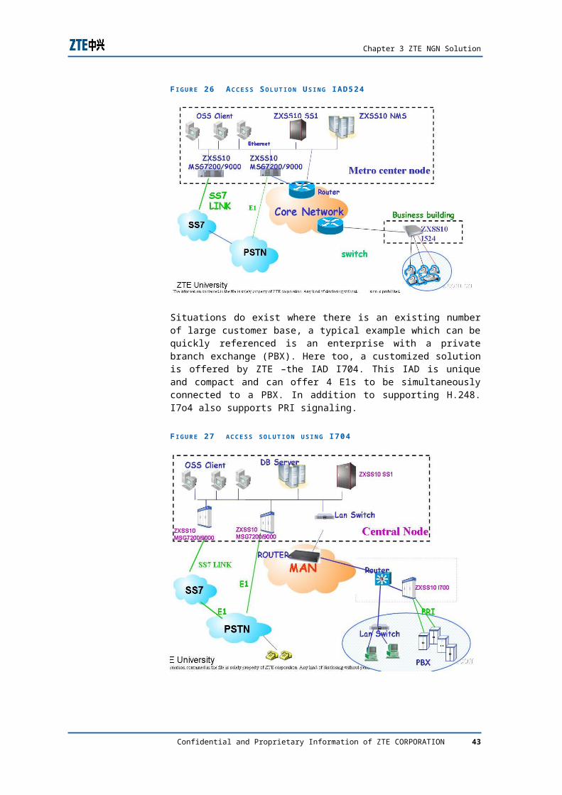
F I G U R E 26 A C C E S S S O L U T I O N U S I N G IAD524
Situations do exist where there is an existing number of large customer base, a typical example which can be quickly referenced is an enterprise with a private branch exchange (PBX). Here too, a customized solution is offered by ZTE –the IAD I704. This IAD is unique and compact and can offer 4 E1s to be simultaneously connected to a PBX. In addition to supporting H.248. I7o4 also supports PRI signaling.
F I G U R E 27 A C C E S S S O L U T I O N U S I N G I 704
Confidential and Proprietary Information of ZTE CORPORATION 37
AG_BT01_E1 Overview of Soft Switch
Co-operating with existing IN network
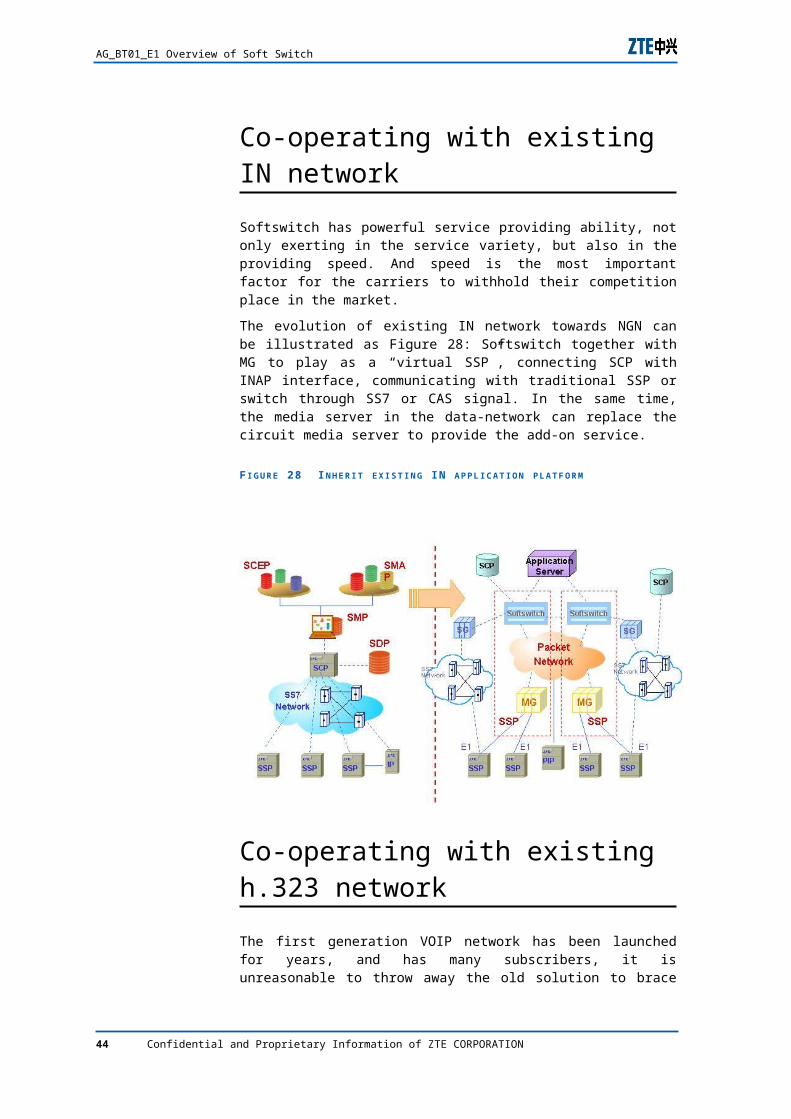
Softswitch has powerful service providing ability, not only exerting in the service variety, but also in the providing speed. And speed is the most important factor for the carriers to withhold their competition place in the market.
The evolution of existing IN network towards NGN can be illustrated as Figure 28: Softswitch together with MG to play as a “virtual SSP”, connecting SCP with INAP interface, communicating with traditional SSP or switch through SS7 or CAS signal. In the same time, the media server in the data-network can replace the circuit media server to provide the add-on service.
F I G U R E 28 I N H E R I T E X I S T I N G IN A P P L I C A T I O N P L A T F O R M
Co-operating with existing h.323 network
The first generation VOIP network has been launched for years, and has many subscribers, it is unreasonable to throw away the old solution to brace the new one. To considering the inter-working with the existing H.323 network has been proposed in the early age of NGN project. The inter-working protocol will use H.323, while softswitch and H.323 belong to different carriers, the interworking point locates between softswitch and 1-level
38 Confidential and Proprietary Information of ZTE CORPORATION
Chapter 3 ZTE NGN Solution
GK. While softswitch and H.323 belong to the same carriers, inter-working point can be assigned by the carrier itself.
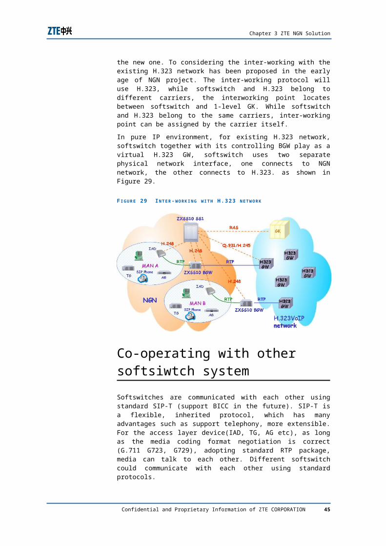
In pure IP environment, for existing H.323 network, softswitch together with its controlling BGW play as a virtual H.323 GW, softswitch uses two separate physical network interface, one connects to NGN network, the other connects to H.323. as shown in Figure 29.
F I G U R E 29 I N T E R -W O R K I N G W I T H H .323 N E T W O R K
Co-operating with other softsiwtch system
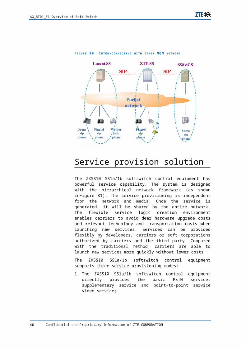
Softswitches are communicated with each other using standard SIP-T (support BICC in the future). SIP-T is a flexible, inherited protocol, which has many advantages such as support telephony, more extensible. For the access layer device(IAD, TG, AG etc), as long as the media coding format negotiation is correct (G.711 G723, G729), adopting standard RTP package, media can talk to each other. Different softswitch could communicate with each other using standard protocols.
Confidential and Proprietary Information of ZTE CORPORATION 39
AG_BT01_E1 Overview of Soft Switch
F I G U R E 30 I N T E R -C O N N E C T I N G W I T H O T H E R NGN N E T W O R K
Service provision solution
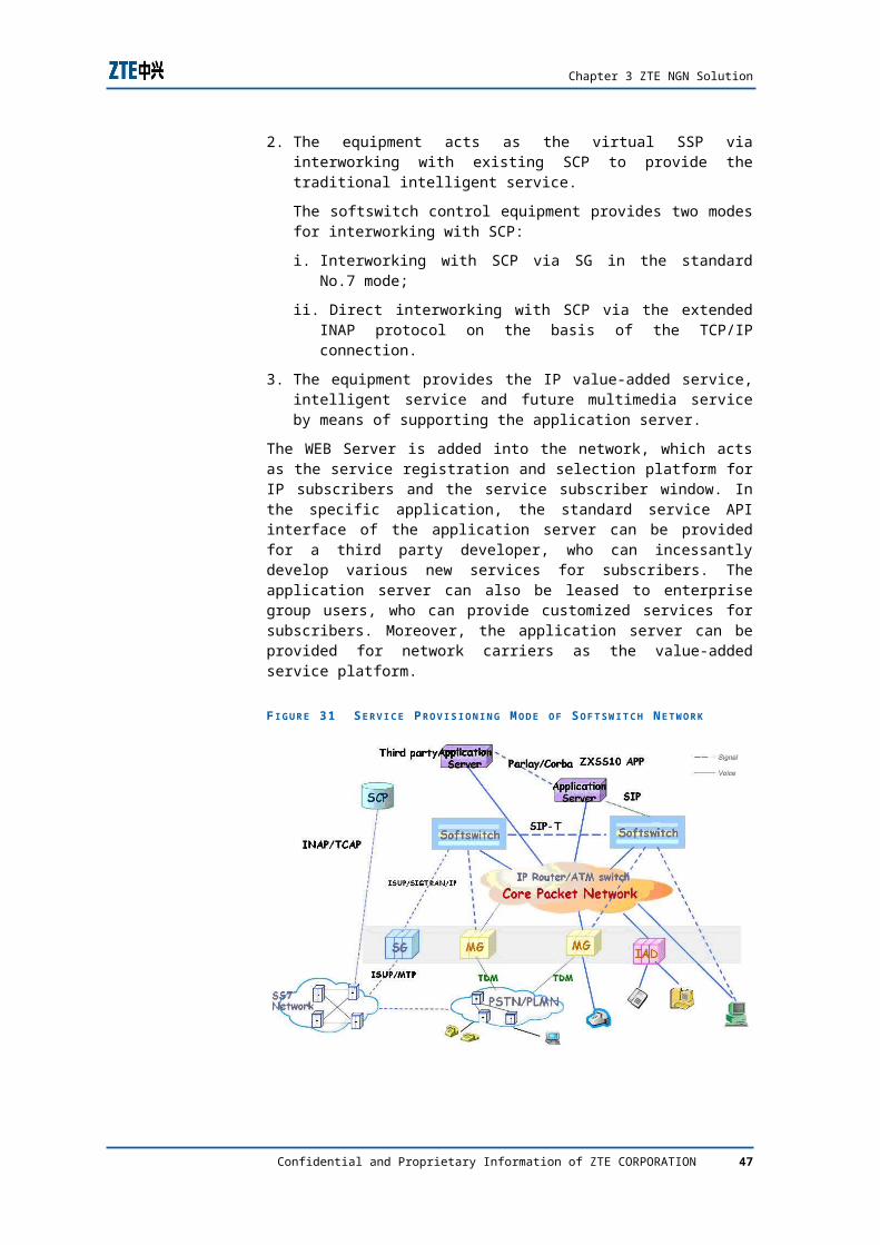
The ZXSS10 SS1a/1b softswitch control equipment has powerful service capability. The system is designed with the hierarchical network framework (as shown inFigure 31). The service provisioning is independent from the network and media. Once the service is generated, it will be shared by the entire network. The flexible service logic creation environment enables carriers to avoid dear hardware upgrade costs and relevant technology and transportation costs when launching new services. Services can be provided flexibly by developers, carriers or soft corporations authorized by carriers and the third party. Compared with the traditional method, carriers are able to launch new services more quickly without lower costs
The ZXSS10 SS1a/1b softswitch control equipment supports three service provisioning modes:
1. The ZXSS10 SS1a/1b softswitch control equipment directly provides the basic PSTN service, supplementary service and point-to-point service video service;
2. The equipment acts as the virtual SSP via interworking with existing SCP to provide the traditional intelligent service.
The softswitch control equipment provides two modes for interworking with SCP:
i. Interworking with SCP via SG in the standard No.7 mode;
ii. Direct interworking with SCP via the extended INAP protocol on the basis of the TCP/IP connection.
3. The equipment provides the IP value-added service, intelligent service and future multimedia service by means of supporting the application server.
40 Confidential and Proprietary Information of ZTE CORPORATION
Chapter 3 ZTE NGN Solution
The WEB Server is added into the network, which acts as the service registration and selection platform for IP subscribers and the service subscriber window. In the specific application, the standard service API interface of the application server can be provided for a third party developer, who can incessantly develop various new services for subscribers. The application server can also be leased to enterprise group users, who can provide customized services for subscribers. Moreover, the application server can be provided for network carriers as the value-added service platform.
F I G U R E 31 S E R V I C E P R O V I S I O N I N G M O D E O F S O F T S W I T C H N E T W O R K
New service introduction
WEB 800 service
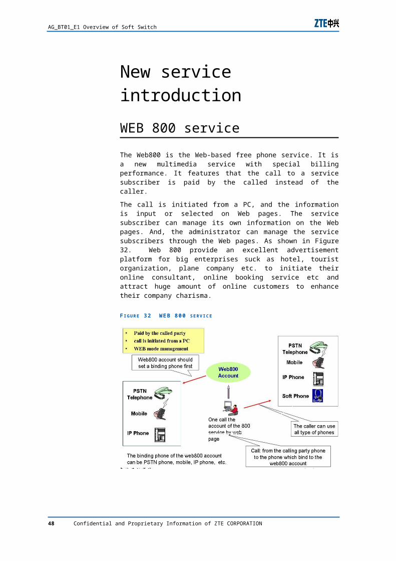
The Web800 is the Web-based free phone service. It is a new multimedia service with special billing performance. It features that the call to a service subscriber is paid by the called instead of the caller.
The call is initiated from a PC, and the information is input or selected on Web pages. The service subscriber can manage its own information on the Web pages. And, the administrator can manage the service subscribers through the Web pages. As shown in Figure 32. Web 800 provide an excellent advertisement platform for big enterprises suck as hotel, tourist organization, plane company etc. to initiate their online consultant, online booking service etc and attract huge amount of online customers to enhance their company charisma.
Confidential and Proprietary Information of ZTE CORPORATION 41
AG_BT01_E1 Overview of Soft Switch
F I G U R E 32 WEB 800 S E R V I C E
Service properties
1. service utilization
User select its 800 service number and fill in its own telephone number, accomplish the service by clicking the webpage button, user can also fill in known 800 service number.
2. billing
accomplish subscriber billing function, bill goes to the user account which has been bound to the service, while charge no money towards the caller.
3. service data management
service user can manage it own account through webpage, such as changing routing, password etc.
4. subscriber management
5. administrator could change the service user configuration, including add/remove/delete users etc.
6. ONLY
When service user has multiple telephone numbers, it can register a single one web 800 number, for those who access the 800 number users, system will divert the calls to different destinations according to the service user requirements.
7. busy/no answer divert
one service user can define multiple destination numbers, system could automatically divert a call from a busy destination to a free one.
8. call blocking
42 Confidential and Proprietary Information of ZTE CORPORATION
Chapter 3 ZTE NGN Solution
service user could define the caller privilege, forbidding subscribers from one certain area to make calls towards another area.
9. time routing
service user could define routing table based on the time schedule
10. temporary routing
service user could define routing table tempararily
11. destination selection
service user could select destination according to its own requirements
12. secure access
service user could define the access password, only those who enter the correct one are allowed to pass through.
13. management function
service user could define its own property by telephone, add/remove/delete/query/forbit/permit/active/inactive list of subscribers.
Web Conference
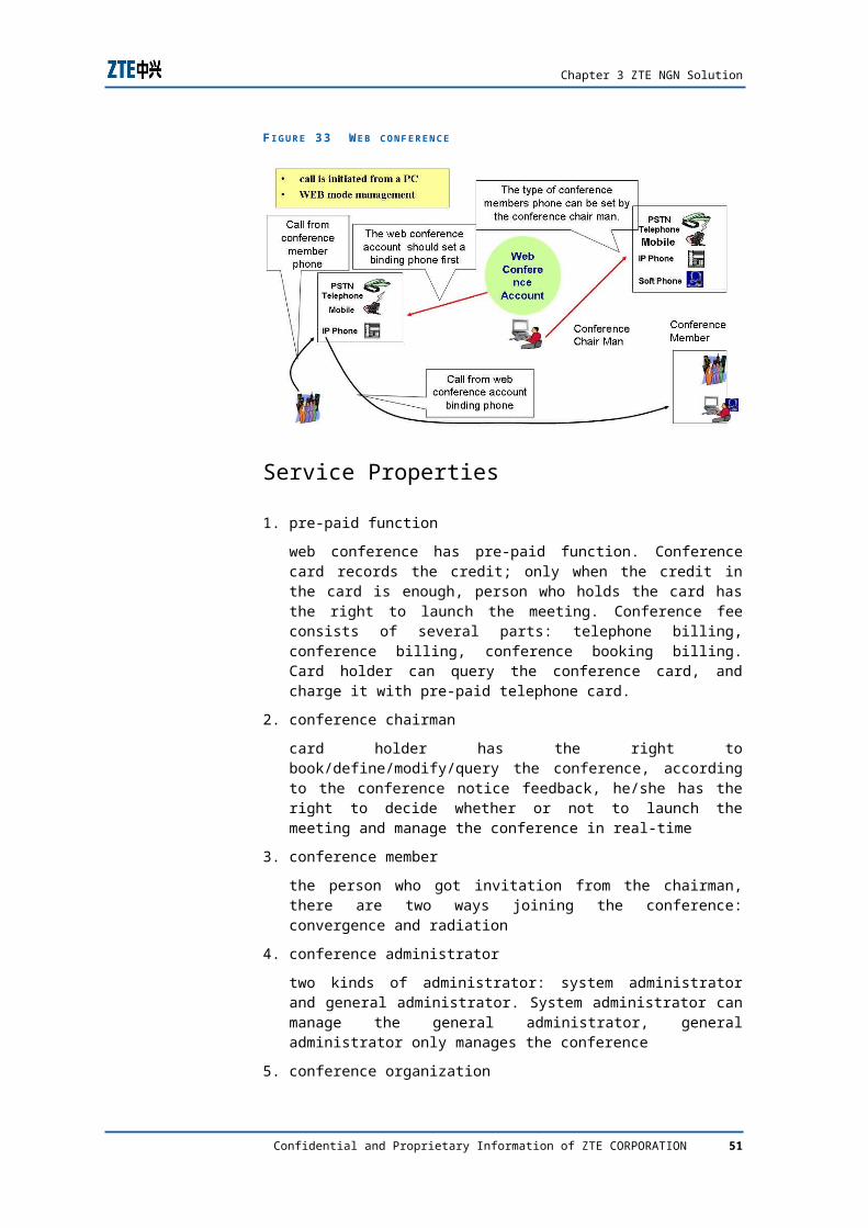
Web Conference is a web-based conference call service. Conference information is displayed on web pages, while the conference chair reserves and manages a conference through web pages.
Conference members may also decide whether to attend the conference through the web any of the two interchangeable ways: convergence and distribution. Sub-conferences are provided and the conference can be recorded in full. The system supports conference joining via a variety of terminals
Web conference service poses excellent potential market for government and educational organization. Government could initiate meeting and communicate with upper/lower agencies, educational organization could launch remote education easily by using such service.
Confidential and Proprietary Information of ZTE CORPORATION 43
AG_BT01_E1 Overview of Soft Switch
F I G U R E 33 W E B C O N F E R E N C E
Service Properties
1. pre-paid function
web conference has pre-paid function. Conference card records the credit; only when the credit in the card is enough, person who holds the card has the right to launch the meeting. Conference fee consists of several parts: telephone billing, conference billing, conference booking billing. Card holder can query the conference card, and charge it with pre-paid telephone card.
2. conference chairman
card holder has the right to book/define/modify/query the conference, according to the conference notice feedback, he/she has the right to decide whether or not to launch the meeting and manage the conference in real-time
3. conference member
the person who got invitation from the chairman, there are two ways joining the conference: convergence and radiation
4. conference administrator
two kinds of administrator: system administrator and general administrator. System administrator can manage the general administrator, general administrator only manages the conference
5. conference organization
two ways of joining the conference: convergence and radiation. Convergent way is that the conference member dialing the conference access code and password after the launching and been patched to the conference. Radiation way is that the system automatically calls the conference member, the member off-hook the handler and join the conference
44 Confidential and Proprietary Information of ZTE CORPORATION
Chapter 3 ZTE NGN Solution
6. conference booking
conference chairman can book conference, filling start time, end time, members, for radiation way, he/she needs to fill in the telephone number.
7. conference status display/management
chairman can observe the conference status and engage certain operations.
8. sub-conference
conference member could ask for join/quit sub-conference
9. multi-trial calling
for radiation way users, system could launch several trails to make sure the member attend the meeting
10. address book
chairman can has its own address book, adding usual conference member.
Web Call
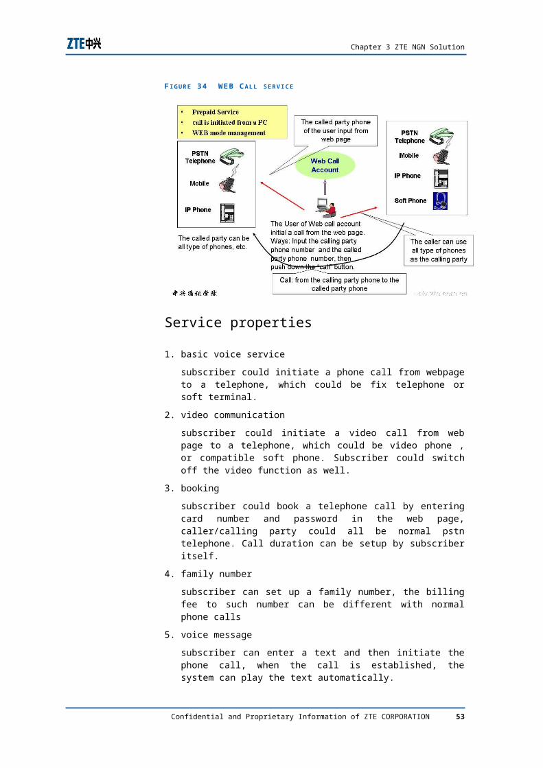
Web Call is a prepaid service which initial call from Web Page.
F I G U R E 34 WEB C A L L S E R V I C E
Service properties
1. basic voice service
Confidential and Proprietary Information of ZTE CORPORATION 45
AG_BT01_E1 Overview of Soft Switch
subscriber could initiate a phone call from webpage to a telephone, which could be fix telephone or soft terminal.
2. video communication
subscriber could initiate a video call from web page to a telephone, which could be video phone , or compatible soft phone. Subscriber could switch off the video function as well.
3. booking
subscriber could book a telephone call by entering card number and password in the web page, caller/calling party could all be normal pstn telephone. Call duration can be setup by subscriber itself.
4. family number
subscriber can set up a family number, the billing fee to such number can be different with normal phone calls
5. voice message
subscriber can enter a text and then initiate the phone call, when the call is established, the system can play the text automatically.
ONLY
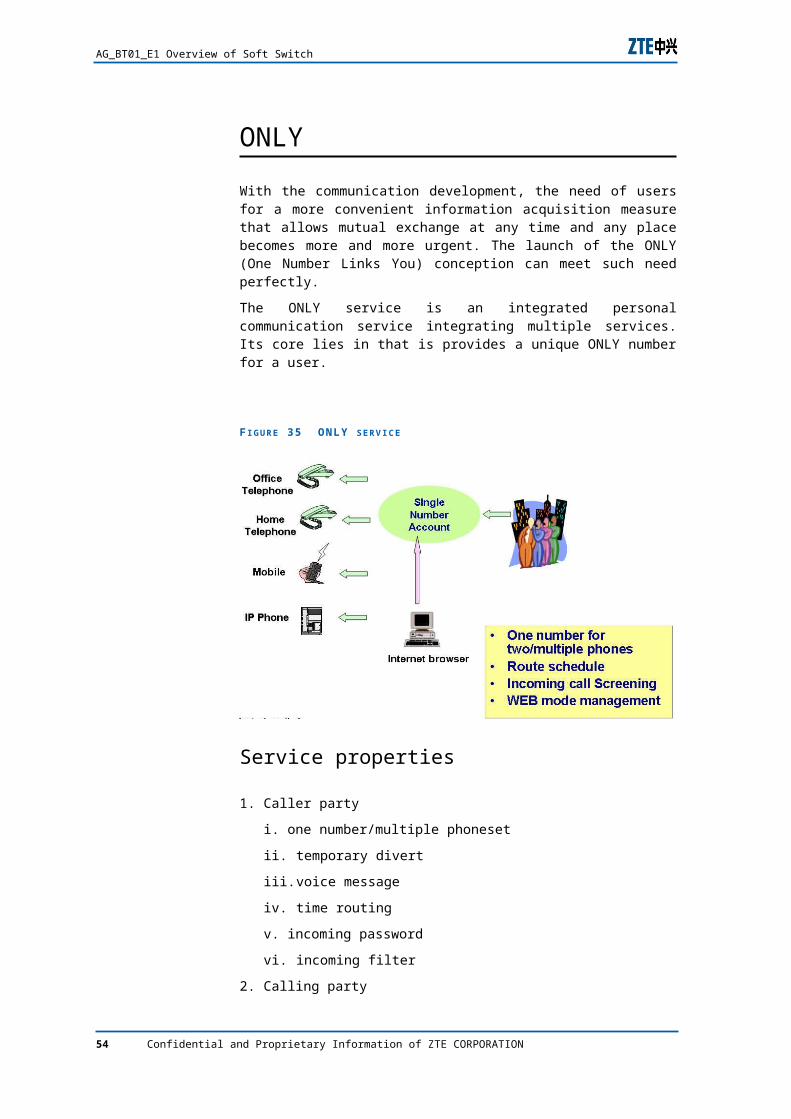
With the communication development, the need of users for a more convenient information acquisition measure that allows mutual exchange at any time and any place becomes more and more urgent. The launch of the ONLY (One Number Links You) conception can meet such need perfectly.
The ONLY service is an integrated personal communication service integrating multiple services. Its core lies in that is provides a unique ONLY number for a user.
46 Confidential and Proprietary Information of ZTE CORPORATION
Chapter 3 ZTE NGN Solution
F I G U R E 35 ONLY S E R V I C E
Service properties
1. Caller party
i. one number/multiple phoneset
ii. temporary divert
iii. voice message
iv. time routing
v. incoming password
vi. incoming filter
2. Calling party
i. ONLY account billing
ii. Personal password management
iii. Continuous dialing
iv. Calling limit
v. Calling destination limit
Confidential and Proprietary Information of ZTE CORPORATION 47
C h a p t e r 4
Dual-homing Technology
Key points
Basic concept of dual-homing.
Operating principle of dual-homing.
Data configuration when applying dual-homing technology.
Basic concepts of dual-homing
As next generation network core control device, softswitch will control all the access gateway and terminal devices, if something wrong happens in ss side, the result will be disaster and affect each and every subscribers which have been registered towards which. There fore, the requirement of reliability of softswitch is very high so that every board of softswitch should have backup partners. However, this yet could not prevent some certain accidents such as fire alarms, earthquakes etc. In order to enhance the security and reliability of softswitch device, ZTE proposed the dual-homing functionality for softswitch: allocate two softswitch with same configuration to carry half of the traffic respectively, they work together as partners and controls half of the network, when one softswitch cannot work properly, the subordinates it controlled will automatically switch their commander to another one, and restore the communication in the shortest time.
In such network configuration, every gateway and terminal will have two devices :main and assistant.
Confidential and Proprietary Information of ZTE CORPORATION 49
F I G U R E 36 B A S I C C O N C E P T S O F D U A L -H O M I N G
Dual-homing implementation principle
In the network designation, adopting dual-homing principle, each device will control half of the network resources.
1. Network resources have been divided equally into halves and assigned to two zones controlled by an individual softswitch.
2. the main/assistant softswitch engage data synchronization in the back stage to ensure the data integration
3. heartbeat mechanism ensures the working status checking between SS and SS, SS and terminals, SS and gateways.
F I G U R E 37 D U A L -H O M I N G I M P L E M E N T A T I O N P R I N C I P L E
Confidential and Proprietary Information of ZTE CORPORATION 50
Chapter 4 Dual-homing Technology
Switching principle based on H.248
Service switching mechanism: auto switching / manual switching
Service switching back: while the problem softswitch restores status, switch back the service manually or automatically
1. two kinds of heartbeats: one is coming from SS, which is the Audit message in H.248. mainly initialized by SS to check the gateway status, if there is no answer, SS consider the gateway device has switched to another backup SS, and divert the associate calling route to a backup device.
2. the other one is coming from gateway, supporting servicechange message or notify message, if there is no response, gateway will resend the message.
3. time intervals of message between Softswitches is 2ms, heartbeat adopts standard SIP OPTION message. Softswitch sends OPTIONS message, if there is no response, it will resend the message in time interval: 0.5s, 1s, 2s, 4s, 4s, 4s, 4s,4s, 4s. and will send 11 messages at most. After 40s from the first OPTION message, softswitch will consider it as off-line.
F I G U R E 38 D U A L H O M I N G I N H .248
Confidential and Proprietary Information of ZTE CORPORATION 51
AG_BT01_E1 Overview of Soft Switch
Data configuration for dual-homing
SS side data configuration
In dual-homing, the configuration of SS that plays as partners must keep the same, including their fore-end, back-end and database server.
To ensure the data integration, using the philosophy as:
1. local area data configuration is mainly configured through local clients or local billing/accounting system
2. assistant data configuration is initialized through the back-stage database serer.
3. In the SS configuration, add an additional note in “OTHER SS” area and set up as mapping relationship
F I G U R E 39 SS S I D E C O N F I G U R A T I O N F O R D U A L -H O M I N G
TG side data configuration
In the NGN architecture, TG, AG, IAD devices must register towards one and only one softswitch, which means that these devices can only controlled by one softswitch at a time. The data in other softswitch is not active. Therefore, the gateway needs to be configured a main and a backup MGC information.
52 Confidential and Proprietary Information of ZTE CORPORATION
Chapter 4 Dual-homing Technology
F I G U R E 40 TG S I D E C O N F I G U R A T I O N F O R D U A L -H O M I N G
SG side data configuration
To communicate with PSTN switches, softswitch needs to use SS7 signals. The role of SG and SS is considered equally in IP network, SG owns its own SPC code as well. In the SG configuration, two signal links (accompanied by two ASP links) connect the SSs respectively, while only one of them is active in normal working mode.
Similarly, in the SS side, it is also necessary to configure two SCTP links pointing to the SG respectively.
F I G U R E 41 SG S I D E C O N F I G U R A T I O N F O R D U A L -H O M I N G
Confidential and Proprietary Information of ZTE CORPORATION 53
AG_BT01_E1 Overview of Soft Switch
3rd-party SS data configuration
To achieve the inter-working with 3rd-party devices, the requirements to 3rd-party SS will be:
1. while configuring the subordinates of SSA, the outgoing IP route to SSA must be setup as direct route, to SSB route as indirect one.
2. while configuring the subordinates of SSB, the outgoing IP route to SSB must be setup as direct route, to SSA route as indirect one.
F I G U R E 42 3 R D P A R T Y C O N F I G U R A T I O N F O R D U A L -H O M I N G
Billing, accounting management in dual-homing
For billing and accounting system, in order to maintain the subscriber data integrity, and forbid one subscriber two CDRs, only the main user data can be modified, while the backup user data should merely be synchronized from the other end.
Local billing/accounting system modifies the subscriber data, accomplish data synchronization through message invoking
Billing of local call is initiated by main SS, while switching to assistant softswitch, the assistant will take over the billing task.
54 Confidential and Proprietary Information of ZTE CORPORATION
Chapter 4 Dual-homing Technology
F I G U R E 43 B I L L I N G , A C C O U N T I N G M A N A G E M E N T C O N F I G U R A T I O N F O R D U A L -H O M I N G
Confidential and Proprietary Information of ZTE CORPORATION 55
Figures
Figure 1 Telephone history (switching history)...........................2
Figure 2 OSI Model......................................................................8
Figure 3 OSI Model and its protocols...........................................8
Figure 4 TCP/IP protocol..............................................................9
Figure 5 IP address example.....................................................10
Figure 6 IP address illustration..................................................10
Figure 7 IP address classes.......................................................12
Figure 8 LAN, MAN and WAN.....................................................13
Figure 9 Next-generation Network Based on the Softswitch Technology................................................................................18
Figure 10 Front view of the ZXSS10 SS1a (4U).........................20
Figure 11 Rear view of the ZXSS10 SS1a (4U)..........................20
Figure 12 Front view of the ZXSS10 SS1b shelf (12U)...............21
Figure 13 Rear view of the ZXSS10 SS1b Shelf (12U)...............21
Figure 14 ZXMSG9000 rack structure.......................................22
Figure 15 IAD series products...................................................24
Figure 16 NGN protocol family..................................................25
Figure 17 Transaction, Action and Command Relationships.....26
Figure 18 SIGTRAN Signaling Transmission Function Model......27
Figure 19 SIGTRAN Protocol Stack Model..................................27
Figure 20 Schematic Diagram of ISUP Message Transmitted Through SG................................................................................29
Figure 21 Schematic Diagram of SCCP Signaling Transmission 29
Figure 22 Management Message Transmission Model..............30
Figure 23 Using B100 to solve private-public address mapping32
Figure 24 Class 4 Replacement solution Using Softswitch........35
Figure 25 Access Solution –Cable Via IAD600...........................36
Figure 26 Access Solution Using IAD524...................................37
Figure 27 access solution using I704........................................37
Figure 28 Inherit existing IN application platform.....................38
Figure 29 Inter-working with H.323 network.............................39
Confidential and Proprietary Information of ZTE CORPORATION 57
Figure 30 Inter-connecting with other NGN network.................40
Figure 31 Service Provisioning Mode of Softswitch Network.....41
Figure 32 WEB 800 service.......................................................42
Figure 33 Web conference........................................................44
Figure 34 WEB Call service.......................................................45
Figure 35 ONLY service.............................................................47
Figure 36 Basic concepts of dual-homing.................................50
Figure 37 Dual-homing implementation principle.....................50
Figure 38 Dual homing in H.248...............................................51
Figure 39 SS side configuration for dual-homing......................52
Figure 40 TG side configuration for dual-homing......................53
Figure 41 SG side configuration for dual-homing......................53
Figure 42 3rd party configuration for dual-homing.....................54
Figure 43 Billing, accounting management configuration for dual-homing...............................................................................55
Confidential and Proprietary Information of ZTE CORPORATION 58