Embed Size (px)
Citation preview

HEADSIGHT.COM | 574.546.5022
Corn Header Manual09020401d
AGCO

i
About Headsight
Headsight Contact InfoHeadsight, Inc. 4845 3B Road Bremen, IN 46506 Phone: 574-546-5022 Fax: 574-546-5760 Email: [email protected] Web: www.headsight.com
Technical AssistancePhone: 574-220-5511
About this Manual
How to use this manualThe instructions in this manual are in the order that they should be completed for new installations. Complete all applicable instructions in each section before proceeding. Note that some sections are labeled to indicate they only apply to certain machines or applications. An index is available in the front of the manual to help find technical information for previously installed systems.
This icon designates information of which you should take note.
This icon indicates a special tool needed for a given task.
This icon designates an important instruction.
DisclaimersHeadsight®, Horizon®, Pinpoint®, Insight®, Foresight®, Feathersight® Truesense™ and Truesight® are trademarks of Headsight, Inc. All other trademarks are property of their respective owners.
SuggestionsIf you have any suggestions to improve this manual please call 574-546-5022 or email [email protected].
Headsight’s products are protected by one or more of the following US Patents 6202395, 6833299, 7310931, 7647753, 9609806 and other patents pending.
Copyright Headsight, Inc. 2017
ii
ContentsAbout Headsight ��������������������������������������������������������������������������������������������� iAbout this Manual ������������������������������������������������������������������������������������������� iInstallation �������������������������������������������������������������������������������������������������� 1
Mounting Sensors ���������������������������������������������������������������������������������������� 2AGCO Poly (Outer Rows) ������������������������������������������������������������������������������� 2AGCO Poly (Inner Rows) ������������������������������������������������������������������������������� 3Steel Snouts ��������������������������������������������������������������������������������������������� 4
Routing Wiring �������������������������������������������������������������������������������������������� 5Harness Length Table ���������������������������������������������������������������������������������� 5Removing Wires for Tight Access �������������������������������������������������������������������� 5
Wiring instructions �������������������������������������������������������������������������������������� 6Install Horizon or Insight Controller ������������������������������������������������������������������ 7
Sensor Adjustment ����������������������������������������������������������������������������������������� 8Changing Swing ������������������������������������������������������������������������������������������� 8Increasing or Decreasing Voltage ���������������������������������������������������������������������� 8Sensor Extensions ���������������������������������������������������������������������������������������� 9
Parts ���������������������������������������������������������������������������������������������������������10Corn Sensor ����������������������������������������������������������������������������������������������10Mounting Bracket and Harness �����������������������������������������������������������������������11
STATEMENT OF LIMITED WARRANTY �����������������������������������������������������������������13
1
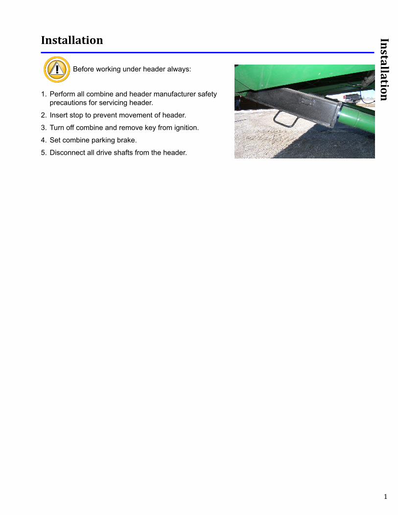
Installation
Installation
Before working under header always:
1. Perform all combine and header manufacturer safety precautions for servicing header.
2. Insert stop to prevent movement of header.
3. Turn off combine and remove key from ignition.
4. Set combine parking brake.
5. Disconnect all drive shafts from the header.
2
Installation
Complete this installation portion of the header manual before continuing.
Mounting Sensors
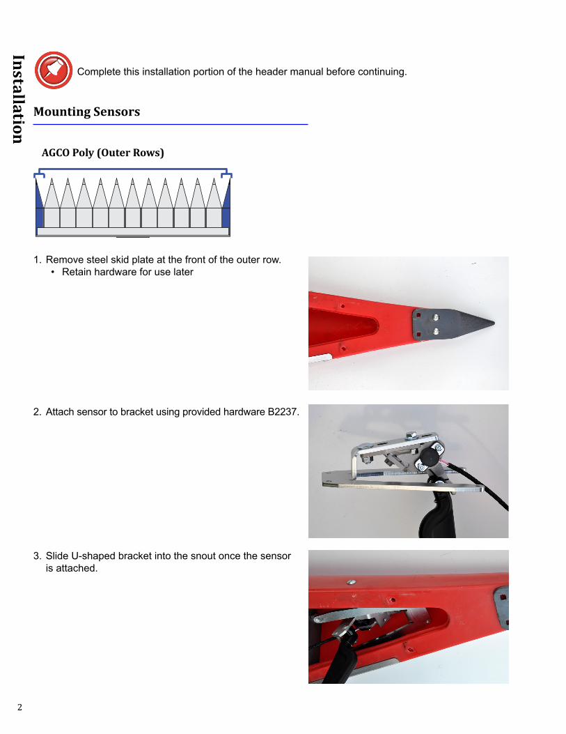
AGCO Poly (Outer Rows)
1. Remove steel skid plate at the front of the outer row.• Retain hardware for use later
2. Attach sensor to bracket using provided hardware B2237.
3. Slide U-shaped bracket into the snout once the sensor is attached.
3
Installation
4. Secure bracket to the snout reusing the hardware removed earlier.
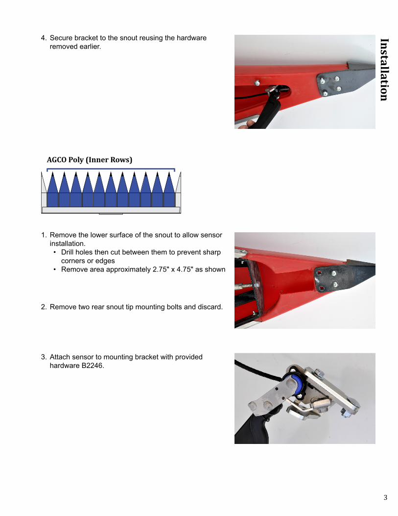
AGCO Poly (Inner Rows)
1. Remove the lower surface of the snout to allow sensor installation. • Drill holes then cut between them to prevent sharp
corners or edges• Remove area approximately 2.75" x 4.75" as shown
2. Remove two rear snout tip mounting bolts and discard.
3. Attach sensor to mounting bracket with provided hardware B2246.
4
Installation
4. Insert bracket into snout and attach with the provided 5/16" x 1" Torx screws.
Steel Snouts
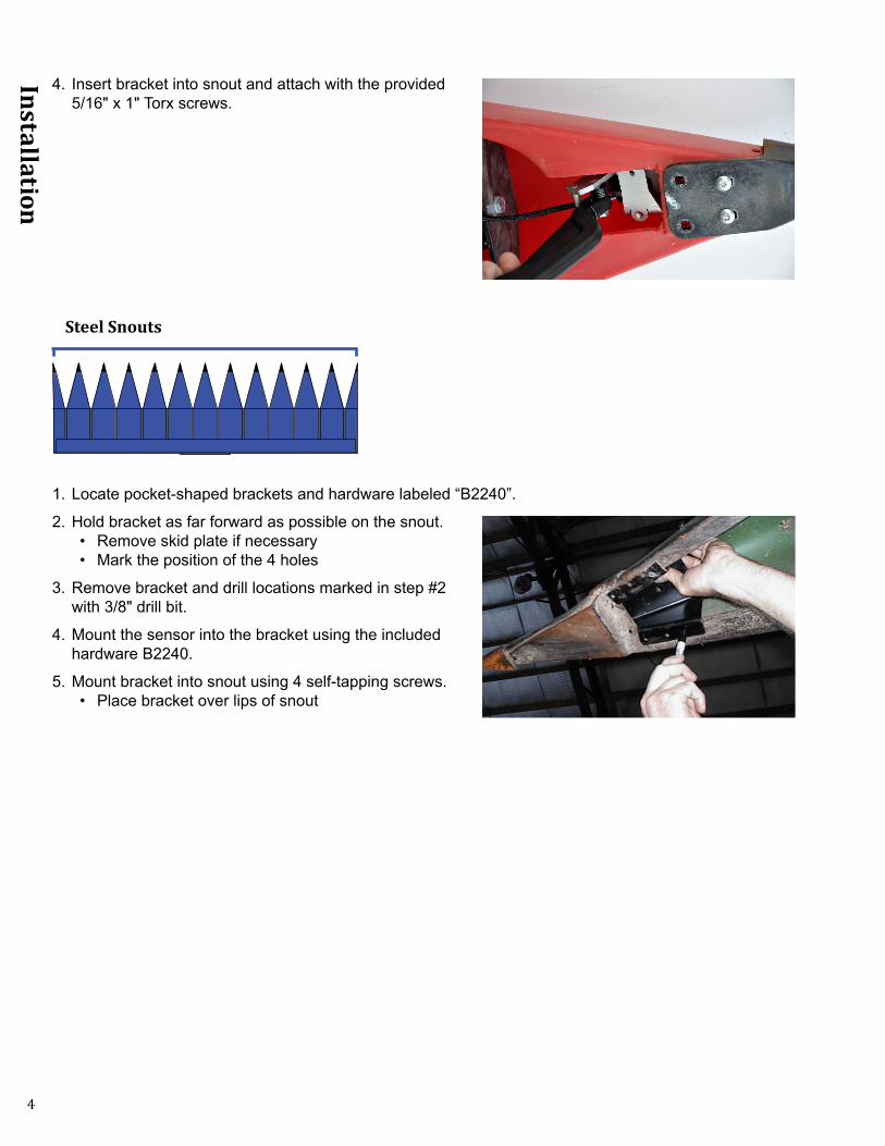
1. Locate pocket-shaped brackets and hardware labeled “B2240”.
2. Hold bracket as far forward as possible on the snout.• Remove skid plate if necessary• Mark the position of the 4 holes
3. Remove bracket and drill locations marked in step #2 with 3/8" drill bit.
4. Mount the sensor into the bracket using the included hardware B2240.
5. Mount bracket into snout using 4 self-tapping screws.• Place bracket over lips of snout
5
Installation
Routing Wiring
1. Select appropriate wiring from chart below and mark blue connector with sensor position.
Properly routing the wiring is the most critical part of the installation process. Please take time to ensure that you have allowed sufficient slack for motion as well as sufficient clearance from moving header parts or crop flow.
Harness Length Table
Header Width Left Left Center Center Right Center RightUp to 20' 17' 17' 33'
21' up to 30' 23' 17' 17' 23' 38'31' up to 40' 38' 17' 17' 33' 33' and 10'41' and up 38' 23' 17' 38' 33' and 17'
*Use Left, Left Center, Center, Right Center and Right for 5 sensor system *Use Left, Left Center, Right Center and Right for 4 sensor system*Use Left, Center and Right for 3 sensor system*Use Left and Right for 2 sensor system
Removing Wires for Tight Access
When routing the wiring, there may be times when you would like to route the wiring through a small hole. You may remove the Weather-Pack connector by using the following procedure. This step is NOT required; it is only shown to aid installation as needed.
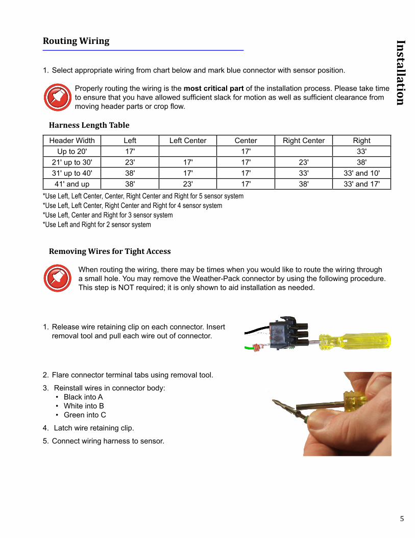
1. Release wire retaining clip on each connector. Insert removal tool and pull each wire out of connector.
2. Flare connector terminal tabs using removal tool.
3. Reinstall wires in connector body:• Black into A• White into B• Green into C
4. Latch wire retaining clip.
5. Connect wiring harness to sensor.
6
Installation
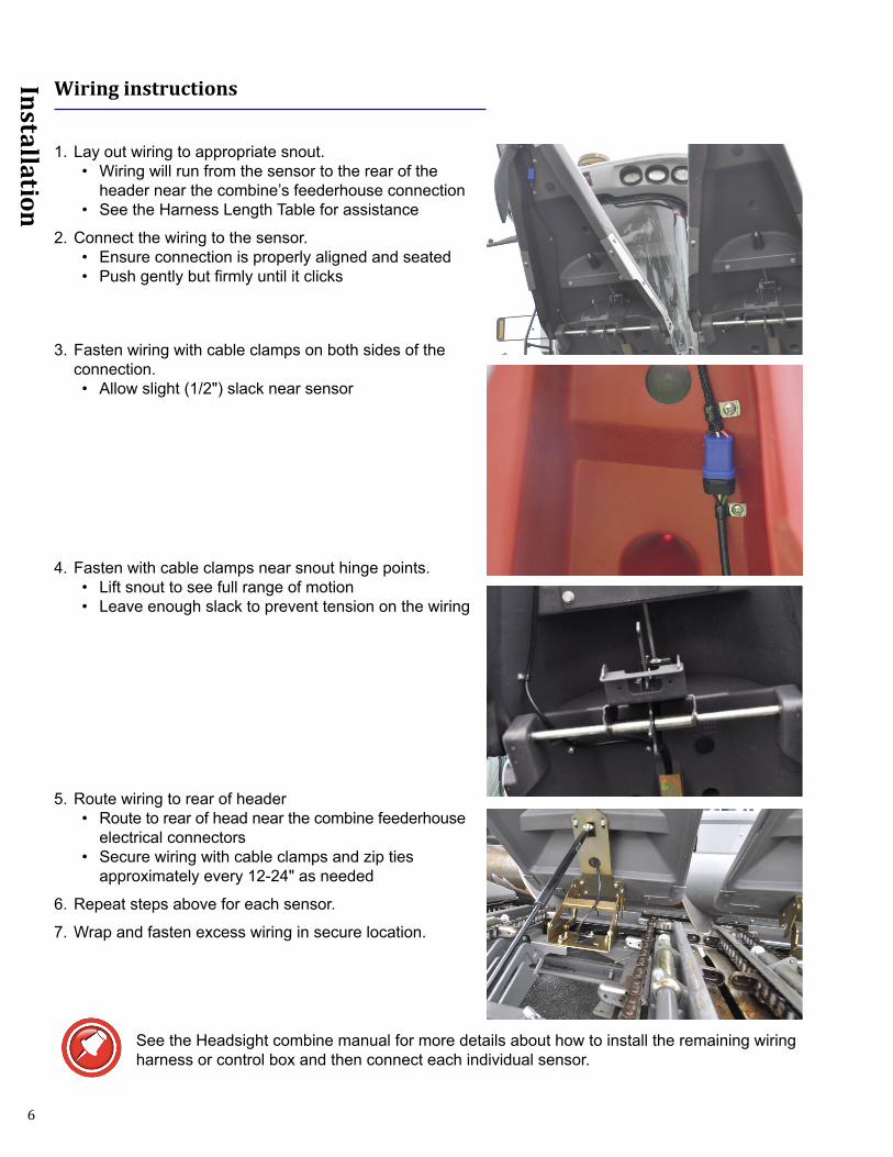
Wiring instructions
1. Lay out wiring to appropriate snout.• Wiring will run from the sensor to the rear of the
header near the combine’s feederhouse connection• See the Harness Length Table for assistance
2. Connect the wiring to the sensor.• Ensure connection is properly aligned and seated• Push gently but firmly until it clicks
3. Fasten wiring with cable clamps on both sides of the connection.• Allow slight (1/2") slack near sensor
4. Fasten with cable clamps near snout hinge points.• Lift snout to see full range of motion• Leave enough slack to prevent tension on the wiring
5. Route wiring to rear of header• Route to rear of head near the combine feederhouse
electrical connectors• Secure wiring with cable clamps and zip ties
approximately every 12-24" as needed
6. Repeat steps above for each sensor.
7. Wrap and fasten excess wiring in secure location.
See the Headsight combine manual for more details about how to install the remaining wiring harness or control box and then connect each individual sensor.
7
Installation
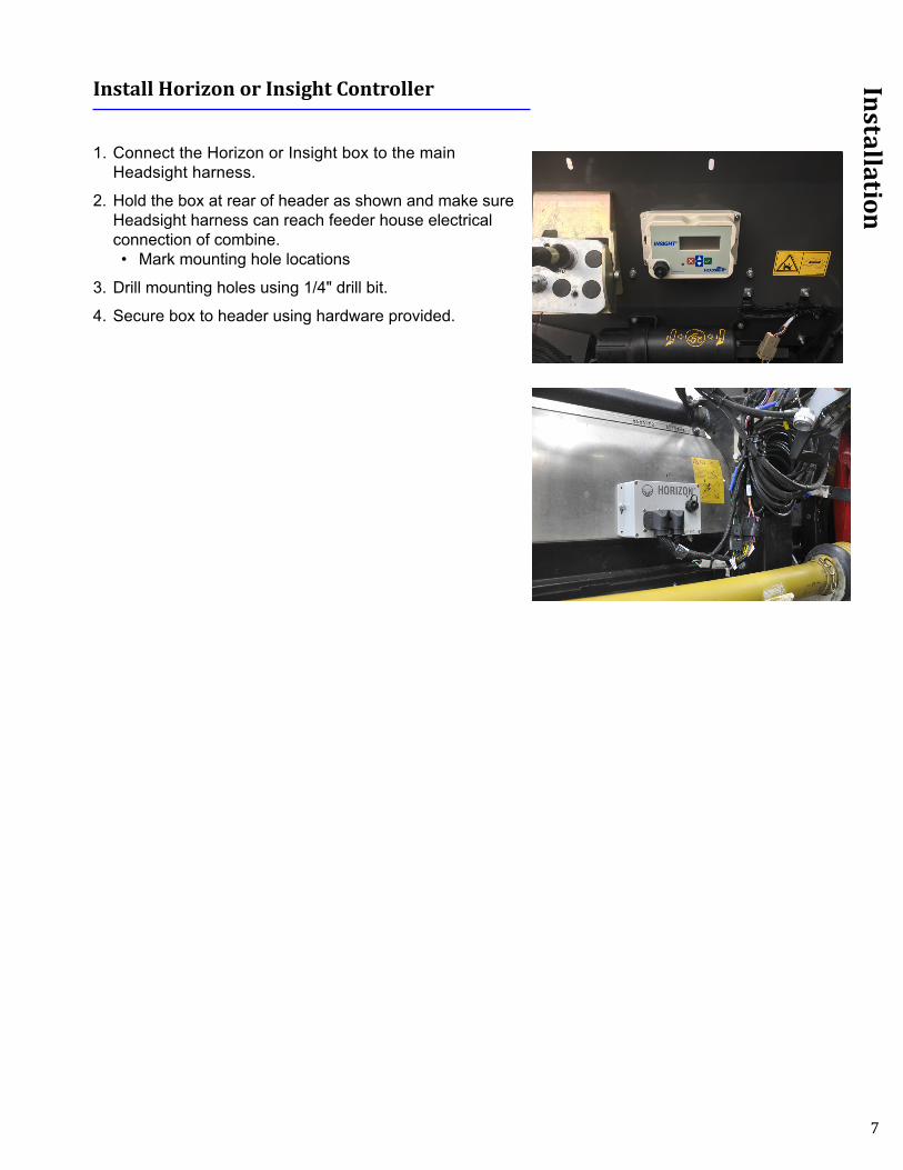
Install Horizon or Insight Controller
1. Connect the Horizon or Insight box to the main Headsight harness.
2. Hold the box at rear of header as shown and make sure Headsight harness can reach feeder house electrical connection of combine.• Mark mounting hole locations
3. Drill mounting holes using 1/4" drill bit.
4. Secure box to header using hardware provided.
8
Sensor Adjustment
Sensor Adjustment
Insert header stop to prevent movement
Changing Swing
1. Loosen the bolt A holding downstop.
2. Slide the downstop to new position in slotted hole.• Raising downstop will increase voltage swing and
allow higher maximum cutting height• Lowering the downstop will decrease total voltage
swing and help prevent arm from “stabbing” the ground when the headers is lowered
Increasing or Decreasing Voltage
1. Loosen sensor mounting nuts B.
2. Twist the sensor to new position using the slotted mounting holes.• Twisting sensor clockwise will lower voltage• Twisting sensor counterclockwise will increase
voltage
3. Retighten the nuts B.
A
BB
9
Sensor Adjustment
Sensor Extensions
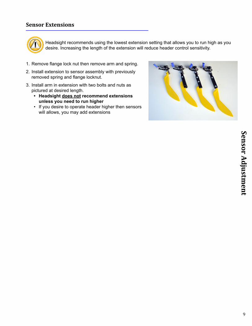
Headsight recommends using the lowest extension setting that allows you to run high as you desire. Increasing the length of the extension will reduce header control sensitivity.
1. Remove flange lock nut then remove arm and spring.
2. Install extension to sensor assembly with previously removed spring and flange locknut.
3. Install arm in extension with two bolts and nuts as pictured at desired length.• Headsight does not recommend extensions
unless you need to run higher• If you desire to operate header higher then sensors
will allows, you may add extensions
10
Parts
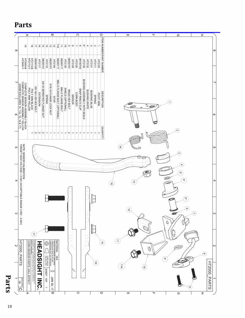
Parts
Corn Sensor
UN
LES
S O
THE
RW
ISE
SP
EC
IFIED
DIM
EN
SIO
NS
AR
E IN
INC
HE
SD
IME
NS
ION
S W
/O TO
L AR
E B
AS
IC
THIR
D A
NG
LEP
RO
JEC
TION
THE
INFO
RM
ATIO
N C
ON
TAIN
ED
ON
THIS
DR
AW
ING
IS P
RO
PR
IETA
RY
TOH
EA
DS
IGH
T, INC
. AN
Y U
NA
UTH
OR
IZED
US
E O
F SU
CH
CO
NTE
NTS
ISS
TRIC
TLY P
RO
HIB
ITED
.
CH
G LE
VE
L
DATE
SH
EE
T OF
HEA
DS
IGH
T IN
C.C
12
34
DCBA
11
E F G H
DCBA E F G H
56
78
12
34
56
78
04H
T2000_PA
RTS
CO
RN
SE
NS
OR
PA
RTS
, HA
LL EFFE
CT
JAN
30, 17
MA
TER
IAL
N/A H
T2000_PA
RTS
ITEM
NU
MB
ER
PA
RT N
UM
BE
RD
ES
CR
IPTIO
NQ
UA
NTITY
1H
T2125P
IVO
T AR
M1
2H
T2111S
PR
ING
13
HT2131
BU
SH
ING
BLU
E 1
4H
T2132B
US
HIN
G W
HITE
15*
HT2139
BU
SH
ING
AS
SE
MB
LY W
ITH S
EA
LS1
608100103
SN
AP
RIN
G E
-CLIP
17
HT2120
CO
RN
BO
DY
18
HT2128
SE
NS
OR
19
08200147 M
5x20 HE
X B
OLT
210
HT2130
SH
IELD
(OP
TION
AL)
111
08200117M
8x12 FLAN
GE
BO
LT1
11A08200117
M8x12 FLA
NG
E B
OLT (O
PTIO
NA
L)1
12H
T2105S
TOP
113
082001515/16-18 FLA
NG
E LO
CK
NU
T1
14H
T2110S
PR
ING
115
082001313/8-16 S
ER
RA
TED
FLAN
GE
NU
T2
16H
T2117E
XTE
NS
ION
217
082001083/8-16x1-3/8 H
EX
BO
LT2
18H
T2113-BH
T2113-YP
OLY
AR
M B
LAC
KP
OLY
AR
M Y
ELLO
W1
19H
T2000-BH
T2000-YC
OM
PLE
TE S
EN
SO
R A
SS
EM
BLY
BLA
CK
CO
MP
LETE
SE
NS
OR
AS
SE
MB
LY Y
ELLO
W(A
SS
M E
XC
LUD
ES
10, 11A, 15, 16 &
17)N
OTE
: SE
NS
OR
CA
LIBR
ATIO
NTA
RG
ET H
IGH
VO
LTAG
E = 4.00V
(AC
CE
PTA
BLE
RA
NG
E 3.95V
- 4.05V)
34
25*
14
13
11
12
6
10
18
1
11A
7
8
9
5*
5*5*
16
17
15
11
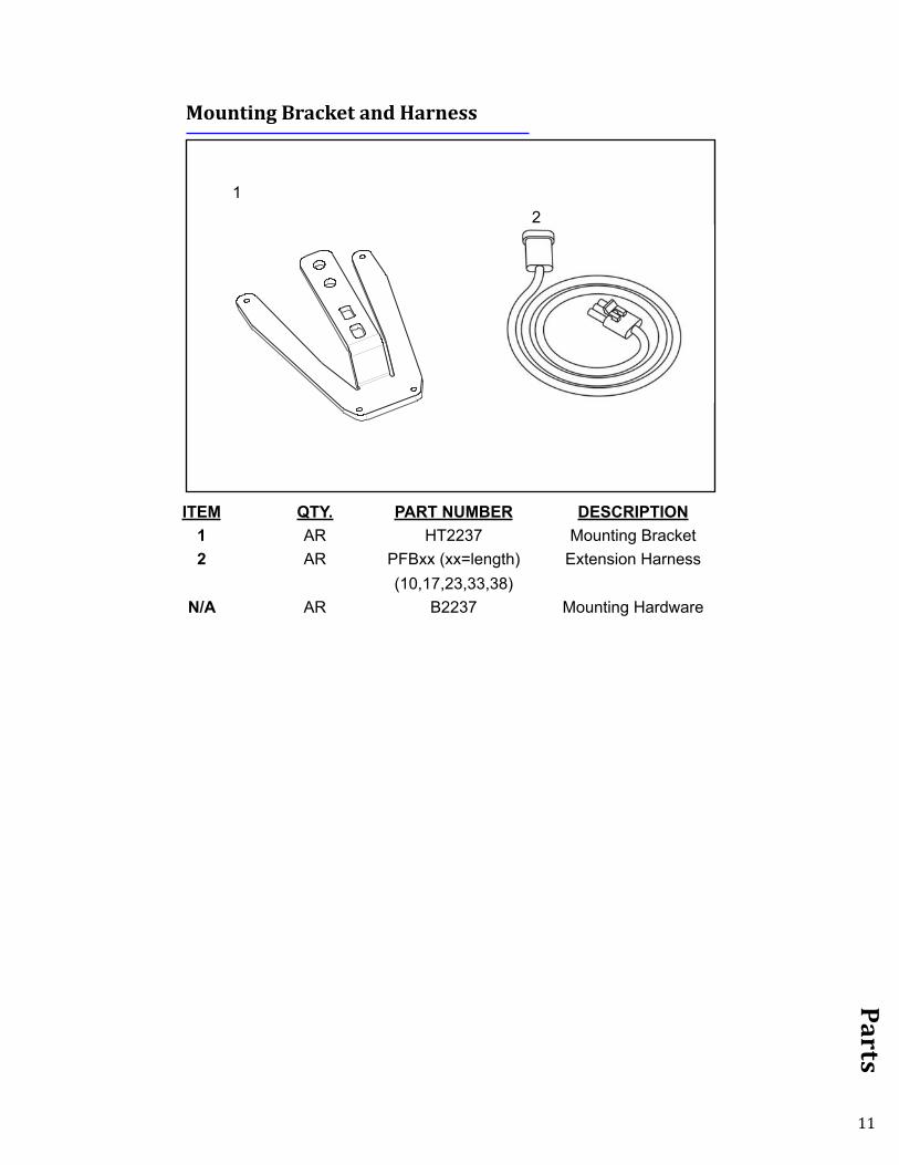
Parts
ITEM QTY. PART NUMBER DESCRIPTION1 AR HT2237 Mounting Bracket2 AR PFBxx (xx=length) Extension Harness
(10,17,23,33,38)N/A AR B2237 Mounting Hardware
Mounting Bracket and Harness
12
UNLESS OTHERWISE SPECIFIEDDIMENSIONS ARE IN INCHESDIMENSIONS W/O TOL ARE BASIC
THIRD ANGLEPROJECTION
THE INFORMATION CONTAINED ON THIS DRAWING IS PROPRIETARY TOHEADSIGHT, INC. ANY UNAUTHORIZED USE OF SUCH CONTENTS ISSTRICTLY PROHIBITED.
CHG LEVEL
DA
TE
SHEET OF
HEADSIGHT INC.
C1234
D
C
B
A
1 1
E
F
G
H
D
C
B
A
E
F
G
H
5678
12345678
1.688±.010
10°1.625±.010
.370
.000
2.005
3.255
4.890
5.260
1.565
3.695
1.3781.060
1.880
3.3803.38
3.8824.174
4X 2.630
2X .425
2X .
870
.000
2X 1
.500
2X 7
.229
8.12
5
9.00
0
6.50
0
7.50
0
2X 8
.615
3.69
2
2X .425
3.87
5
4.87
5
2X .625
4.766 REF
2.760 REF
04HT2237
BRACKET - AGCO OUTER
FEB 5, 16
MATERIAL SEE NOTE 4
HT2237
TOLERANCEx.x = ± .030x.xx = ± .010x.xxx = ± .005ANGLES = ± 1/2°
FLAT PATTERNNOTES:1. BREAK ALL SHARP EDGES, R=.015 MAX2. INNER BEND RADII, R=.06253. FINISH: ZINC PLATE4. MATERIAL: 1/4 SHEET STEEL, HOT ROLLED P & 0
4X 5/16-18 UNC-2B TAP THRU

This PageIs Intentionally
Left Blank
13
STATEMENT OF LIMITED WARRANTY
For Headsight® Products Headsight Inc. (Headsight) warrants its new products to be free from defects in material and workmanship for a period of twelve (12) consecutive months following the date of purchase by the retail purchaser.
Headsight Inc. (Headsight) warrants its new corn sensors assemblies for a period of thirty-six (36) months.
Headsight warrants genuine Headsight replacement parts and components to be free from defects in material and workmanship for a period of six (6) consecutive months following the date of purchase or the remainder of the original equipment warranty period, whichever is longer.
Headsight’s obligation under these warranties shall be limited to repairing or replacing, free of charge to the original purchaser, any part that, in Headsight’s judgment, shows evidence of such defect.
Limitations to Warranty
This warranty does not cover:• Warranty claims directly resulting from improper installation of the product.• Any product damaged by accident, abuse, misuse, or negligence after shipment from Headsight.• Any unauthorized product alteration or modification.• Any unauthorized repairs made with parts other than genuine Headsight parts.• Any repairs performed by anyone other than Headsight or an authorized Headsight dealer unless specifically authorized
by Headsight.
Warranty Procedure• Troubleshooting should be done between farmer/dealer and Headsight through our technical assistance @
574.220.5511. • Labor reimbursement will occur only pre-arranged through Headsight technical assistance and be scheduled to a flat rate
basis or reasonable time allowance in Headsight’s judgment. • There is no mileage reimbursement. • Diagnostic time will not be reimbursed except in pre-arranged circumstances.• Warranty claims should be on typical dealer service work order with a number and name to be attached for any future
correspondence. • All warranty work must be performed, and claims submitted, within thirty (30) days of the occurrence of the claim and
within the warranty period.• All parts removed during warranty repair must be returned to Headsight with Headsight’s Return Form within thirty (30)
days of the occurrence of the claim and within the warranty period.• Headsight, Inc. reserves the right to either inspect the product at the original retail purchaser’s location or require it to be
returned to Headsight, Inc. for inspection.
Limitation of LiabilityHeadsight makes no express warranties other than those, which are specifically described herein. Any description of the goods sold hereunder, including any reference to buyer’s specifications and any descriptions in circulars and other written material published by Headsight is for the sole purpose of identifying such goods and shall not create an express warranty that the goods shall conform to such description.
THIS WARRANTY IS EXPRESSLY IN LIEU OF ALL OTHER WARRANTIES EXPRESSED OR IMPLIED. There are no implied warranties of merchantability or fitness of a particular purpose. This warranty states Headsight’s entire and exclusive liability and buyer’s exclusive remedy or any claim for damages in connection with the sale of furnishing of Headsight products, their design, suitability for use, installation or operation, or for any claimed defects herein. HEADSIGHT WILL IN NO EVENT BE LIABLE FOR ANY INCIDENTAL OR CONSEQUENTIAL DAMAGES WHATSOEVER, NOR FOR ANY SUM IN EXCESS OF THE PRICE RE-CEIVED FOR THE GOODS FOR WHICH LIABILITY IS CLAIMED.
No representative of Headsight nor any dealer associated with Headsight has the authority to change the items of this warranty in any manner whatsoever, and no assistance to purchaser by Headsight in the repair of operation of any Headsight product shall constitute a waiver of the conditions of this warranty, nor shall such assistance extend or revive it.
Headsight reserves the right to make improvements in design or changes in specifications at any time, without incurring any obligation to owners of units previously sold. Warranty: 1/2017

P 574.546.5022 • F 574.546.57604845 3B Rd • Bremen, IN [email protected]


![6 . Wiring Diagram Legacy/Service Manual/1996 LEGACY RH… · 6-3 [D601] WIRING DIAGRAM 6 . Wiring Diagram 6 . Wiring Diagram Battery current 1 . POWER SUPPLY ROUTING Current from](https://img.pdfslide.net/doc/110x75/6058f70ca8a7ee39513c5dc6/6-wiring-legacyservice-manual1996-legacy-rh-6-3-d601-wiring-diagram-6-.jpg)


![ELECTRICAL & POWER CONTROL PGB A - NICOclub < component diagnosis > [power supply&ground circuit] power supply routing circuit wiring diagram - battery power supply fuse no](https://img.pdfslide.net/doc/110x75/610d80e95794fd494a1bc426/electrical-power-control-pgb-a-nicoclub-component-diagnosis-power.jpg)