Embed Size (px)
Citation preview
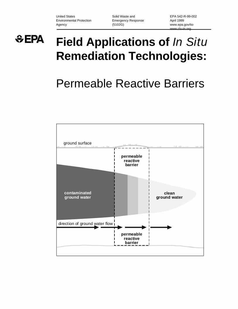
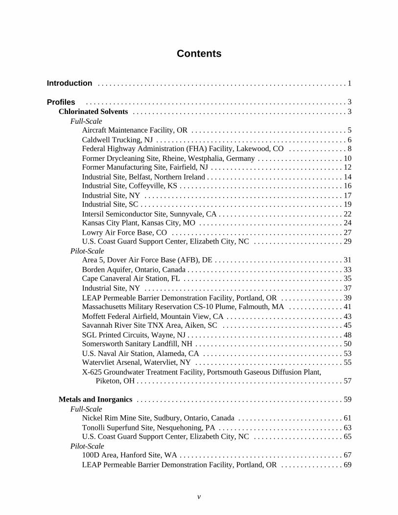
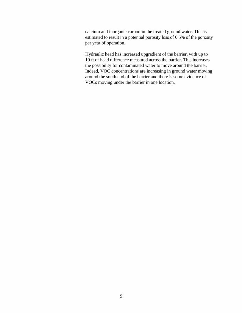
contaminatedground water
cleanground water
permeablereactivebarrier
direction of ground water flow
ground surface
permeablereactivebarrier
United States Solid Waste and EPA 542-R-99-002Environmental Protection Emergency Response April 1999Agency (5102G) www.epa.gov/tio
www.clu-in.org
Field Applications of In SituRemediation Technologies:
Permeable Reactive Barriers

i
EPA-542-R-99-002April 1999
Field Applications of In Situ Remediation Technologies:
Permeable Reactive Barriers
U.S. Environmental Protection AgencyOffice of Solid Waste and Emergency Response
Technology Innovation OfficeWashington, DC 20460
Walter W. Kovalick, Jr., Ph.D., Director
ii
Notice
This report was prepared by Environmental Management Support, Inc., 8601 Georgia Avenue, Suite500, Silver Spring, MD 20910 under contract 68-W6-0014, work assignment 104, with the U.S.Environmental Protection Agency. Mention of trade names or commercial products does not constituteendorsement or recommendation for use. For more information about this project contact: DawnCarroll, U.S. EPA, Technology Innovation Office (5102G), 401 M Street, S.W., Washington DC20460, phone: 703-603-1234, e-mail: [email protected].
iii
Foreword
Approximately 85% of the hazardous waste sites in the United States have contaminated groundwater. The conventional approach for remediating contaminated ground water has been to extract thecontaminated water, treat it above ground, and reinject or discharge the clean water in a processknown as “pump-and-treat.” The recovered contaminants must be disposed of separately. Pump-and-treat technologies require considerable investment over an extended period of time, and it has beenshown that these technologies often do not actually remove the source of the contamination. Currentpolicies and laws stress “permanent” remedies over simple containment methods. Consequently, thereis considerable interest in and effort being expended on alternative, innovative treatment technologiesfor contaminated ground water.
This report is one in a series that documents recent pilot demonstrations and full-scale applications oftechnologies that either treat soil and ground water in place or increase the solubility and mobility ofcontaminants to improve their removal by other remediation technologies. It is hoped that thisinformation will allow more regular consideration of new, less costly, and more effective technologiesto address the problems associated with hazardous waste sites and petroleum contamination. This andthe other reports listed below are available from EPA’s Technology Innovation Office World WideWeb site at http://clu-in.org/pubitech.htm.
Surfactant EnhancementsHydrofracturing/Pneumatic Fracturing
CosolventsElectrokinetics
Thermal EnhancementsIn Situ Chemical Oxidation
Ground-Water Circulation Wells

iv
v
Contents
Introduction . . . . . . . . . . . . . . . . . . . . . . . . . . . . . . . . . . . . . . . . . . . . . . . . . . . . . . . . . . . . . . . . 1
Profiles . . . . . . . . . . . . . . . . . . . . . . . . . . . . . . . . . . . . . . . . . . . . . . . . . . . . . . . . . . . . . . . . . . . 3Chlorinated Solvents . . . . . . . . . . . . . . . . . . . . . . . . . . . . . . . . . . . . . . . . . . . . . . . . . . . . . . . 3
Full-Scale Aircraft Maintenance Facility, OR . . . . . . . . . . . . . . . . . . . . . . . . . . . . . . . . . . . . . . . . 5Caldwell Trucking, NJ . . . . . . . . . . . . . . . . . . . . . . . . . . . . . . . . . . . . . . . . . . . . . . . . . 6Federal Highway Administration (FHA) Facility, Lakewood, CO . . . . . . . . . . . . . . . 8Former Drycleaning Site, Rheine, Westphalia, Germany . . . . . . . . . . . . . . . . . . . . . . 10Former Manufacturing Site, Fairfield, NJ . . . . . . . . . . . . . . . . . . . . . . . . . . . . . . . . . . 12Industrial Site, Belfast, Northern Ireland . . . . . . . . . . . . . . . . . . . . . . . . . . . . . . . . . . . 14Industrial Site, Coffeyville, KS . . . . . . . . . . . . . . . . . . . . . . . . . . . . . . . . . . . . . . . . . . 16Industrial Site, NY . . . . . . . . . . . . . . . . . . . . . . . . . . . . . . . . . . . . . . . . . . . . . . . . . . . 17Industrial Site, SC . . . . . . . . . . . . . . . . . . . . . . . . . . . . . . . . . . . . . . . . . . . . . . . . . . . . 19Intersil Semiconductor Site, Sunnyvale, CA . . . . . . . . . . . . . . . . . . . . . . . . . . . . . . . . 22Kansas City Plant, Kansas City, MO . . . . . . . . . . . . . . . . . . . . . . . . . . . . . . . . . . . . . 24Lowry Air Force Base, CO . . . . . . . . . . . . . . . . . . . . . . . . . . . . . . . . . . . . . . . . . . . . 27U.S. Coast Guard Support Center, Elizabeth City, NC . . . . . . . . . . . . . . . . . . . . . . . 29
Pilot-Scale Area 5, Dover Air Force Base (AFB), DE . . . . . . . . . . . . . . . . . . . . . . . . . . . . . . . . . 31Borden Aquifer, Ontario, Canada . . . . . . . . . . . . . . . . . . . . . . . . . . . . . . . . . . . . . . . . 33Cape Canaveral Air Station, FL . . . . . . . . . . . . . . . . . . . . . . . . . . . . . . . . . . . . . . . . . 35Industrial Site, NY . . . . . . . . . . . . . . . . . . . . . . . . . . . . . . . . . . . . . . . . . . . . . . . . . . . 37LEAP Permeable Barrier Demonstration Facility, Portland, OR . . . . . . . . . . . . . . . . 39Massachusetts Military Reservation CS-10 Plume, Falmouth, MA . . . . . . . . . . . . . . 41Moffett Federal Airfield, Mountain View, CA . . . . . . . . . . . . . . . . . . . . . . . . . . . . . . 43Savannah River Site TNX Area, Aiken, SC . . . . . . . . . . . . . . . . . . . . . . . . . . . . . . . 45SGL Printed Circuits, Wayne, NJ . . . . . . . . . . . . . . . . . . . . . . . . . . . . . . . . . . . . . . . . 48Somersworth Sanitary Landfill, NH . . . . . . . . . . . . . . . . . . . . . . . . . . . . . . . . . . . . . . 50U.S. Naval Air Station, Alameda, CA . . . . . . . . . . . . . . . . . . . . . . . . . . . . . . . . . . . . 53Watervliet Arsenal, Watervliet, NY . . . . . . . . . . . . . . . . . . . . . . . . . . . . . . . . . . . . . . 55X-625 Groundwater Treatment Facility, Portsmouth Gaseous Diffusion Plant, Piketon, OH . . . . . . . . . . . . . . . . . . . . . . . . . . . . . . . . . . . . . . . . . . . . . . . . . . . . . 57
Metals and Inorganics . . . . . . . . . . . . . . . . . . . . . . . . . . . . . . . . . . . . . . . . . . . . . . . . . . . . . 59Full-Scale
Nickel Rim Mine Site, Sudbury, Ontario, Canada . . . . . . . . . . . . . . . . . . . . . . . . . . . 61Tonolli Superfund Site, Nesquehoning, PA . . . . . . . . . . . . . . . . . . . . . . . . . . . . . . . . 63U.S. Coast Guard Support Center, Elizabeth City, NC . . . . . . . . . . . . . . . . . . . . . . . 65
Pilot-Scale100D Area, Hanford Site, WA . . . . . . . . . . . . . . . . . . . . . . . . . . . . . . . . . . . . . . . . . . 67LEAP Permeable Barrier Demonstration Facility, Portland, OR . . . . . . . . . . . . . . . . 69
vi
Fuel Hydrocarbons . . . . . . . . . . . . . . . . . . . . . . . . . . . . . . . . . . . . . . . . . . . . . . . . . . . . . . . . 71 Pilot-Scale
East Garrington, (Near Olds), Alberta, Canada . . . . . . . . . . . . . . . . . . . . . . . . . . . . . 73U.S. Naval Air Station, Alameda, CA . . . . . . . . . . . . . . . . . . . . . . . . . . . . . . . . . . . . 75
Nutrients . . . . . . . . . . . . . . . . . . . . . . . . . . . . . . . . . . . . . . . . . . . . . . . . . . . . . . . . . . . . . . . . 77Full-Scale
Y-12 Site, Oak Ridge National Laboratory, TN . . . . . . . . . . . . . . . . . . . . . . . . . . . . . 79Pilot-Scale
Public School, Langton, Ontario, Canada . . . . . . . . . . . . . . . . . . . . . . . . . . . . . . . . . 82Savannah River Site TNX Area, Aiken, SC . . . . . . . . . . . . . . . . . . . . . . . . . . . . . . . 84
Radionuclides . . . . . . . . . . . . . . . . . . . . . . . . . . . . . . . . . . . . . . . . . . . . . . . . . . . . . . . . . . . . 87Full-Scale
Fry Canyon Site, UT . . . . . . . . . . . . . . . . . . . . . . . . . . . . . . . . . . . . . . . . . . . . . . . . . 89Y-12 Site, Oak Ridge National Laboratory, TN . . . . . . . . . . . . . . . . . . . . . . . . . . . . . 92
Other Organic Contaminants . . . . . . . . . . . . . . . . . . . . . . . . . . . . . . . . . . . . . . . . . . . . . . . 95Full-Scale
Marzone Inc./Chevron Chemical Company, Tifton, GA . . . . . . . . . . . . . . . . . . . . . . 97
Bibliography of Field Applications of Permeable Reactive Barriers . . . . . . . . . . . . . 99
1
Introduction
Purpose and Process
This document is a status report on the use of permeable reactive barriers (PRBs) for ground-waterremediation in the United States, Canada, and selected locations abroad. Included in this report areprofiles of ongoing and completed pilot- and full-scale PRB demonstrations as well as full-scaleinstallations. The profiles are organized by the type of contaminant treated. At some sites, PRBsare being used to address more than one type of contaminant. Profiles for these site are included inall applicable sections of this document.
Sites included were identified by the members of the Permeable Reactive Barriers Action Teamunder the Remediation Technologies Development Forum (RTDF). The Action Team wasestablished in March 1995. Its members include representatives from government, academia, andthe private sector working as partners to achieve public and regulatory acceptance of PRBs forremediating chlorinated solvents, metals, radionuclides, and other ground-water pollutants.
The profiles included in this document have been developed based on information provided by thepoint of contact listed in each profile. The intent is to provide potential users of PRB technologywith information for making more informed decisions and, when possible, to provide pointers toadditional information.
To the extent it is available, a consistent set of information is presented in each profile. Thisincludes site name, location, characteristics of the site, major contaminants, PRB installation date,type of construction, design and installation costs, reactive materials used, results achieved, lessonslearned, and point of contact for further information. This document also includes a bibliographyof PRB-related articles and documents organized alphabetically by author’s name. Some, but notall, of the entries in the bibliography pertain to the sites profiled in the body of the document.
An Internet version of this report is maintained in the Permeable Reactive Barriers Action Teamsection of the RTDF World Wide Web site at www.rtdf.org. Those who have information aboutadditional PRB sites are encouraged to submit it for inclusion in the Web-based version.Additional profiles will be developed as sites are identified, and existing profiles will be updatedperiodically as new information is received. A copy of a “Permeable Reactive Barriers ProfileInformation Request” can be downloaded from the Web site for use in providing appropriateinformation.
2
Technology Needs
Numerous hazardous waste sites have significant concentrations of metals, halogenated organiccompounds, and radionuclides that contaminate ground water. Traditional technologies, such aspump-and-treat, require an external energy source and their cost is high. Subsurface residualsfrequently remain at undesirable levels. Thus, subsurface permeable reactive barriers (PRBs) aregaining a reputation as a cost-effective alternative. Properly designed and installed PRBs canreduce the levels of many contaminants to regulatory cleanup goals. The barriers are expected tohave low maintenance costs, though the stability of aging barriers is still being studied.
Technology Description
A PRB is a passive in situ treatment zone of reactive material that degrades or immobilizescontaminants as ground water flows through it. PRBs are installed as permanent, semi-permanent,or replaceable units across the flow path of a contaminant plume. Natural gradients transportcontaminants through strategically placed treatment media. The media degrade, sorb, precipitate, orremove chlorinated solvents, metals, radionuclides, and other pollutants. These barriers maycontain reactants for degrading volatile organics, chelators for immobilizing metals, nutrients andoxygen to enhance bioremediation, or other agents.
Choice of reactive media for PRBs is based on the specific organic or inorganic contaminant to beremediated. Most PRBs installed to date use zero-valent iron (Fe0) as the reactive media forconverting contaminants to non-toxic or immobile species. For example, Fe0 can reductivelydehalogenate hydrocarbons, such as converting trichloroethylene (TCE) to ethylene, andreductively precipitate anions and oxyanions, such as converting soluble Cr+6 oxides to insolubleCr3 hydroxides. The reactions that take place in the barriers are dependent on parameters such aspH, oxidation/reduction potential, concentrations, and kinetics. The hydrogeologic setting at thesite is also critical—geologic materials must be relatively conductive and a relatively shallowaquitard must be present to contain the system.
Most PRBs are installed in one of two basic configurations: funnel-and-gate or continuous trench,although other techniques using hydrofracturing and driving mandrels are also used. The funnel-and-gate system employs impermeable walls to direct the contaminant plume through a gate, ortreatment zone, containing the reactive media. A continuous trench is installed across the entirepath of the plume and is filled with reactive media.
3
Chlorinated Solvents

4
5
Aircraft Maintenance Facility, OR
Installation Date:March 1998
Contaminants:TCE
Reactive Media:Fe0
Installation Cost:$600,000
Construction:Funnel and Gate
Point of Contact:James RomerEMCON Associates1150 Knutson RoadSuite 5Medford, OR 97504Tel: 541-770-6977Fax: 541-770-7019E-mail:[email protected]
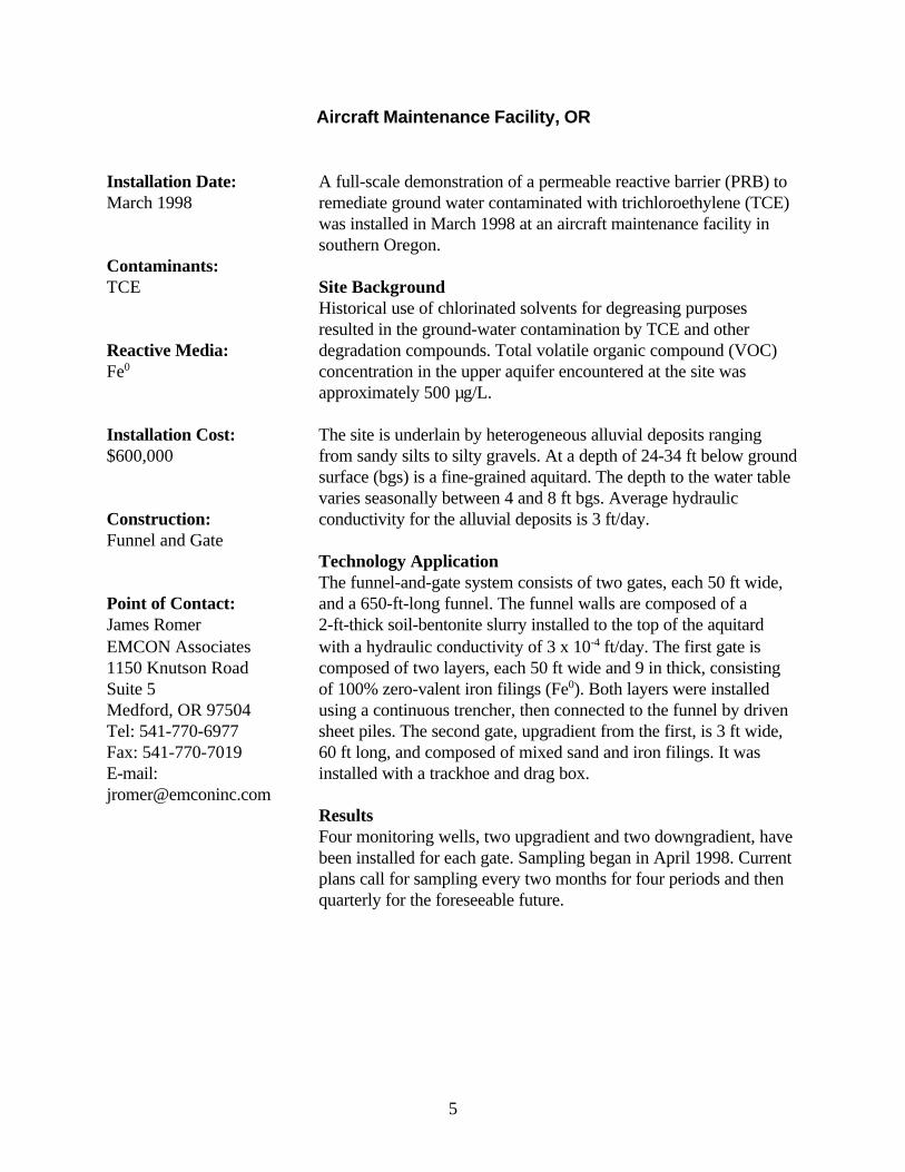
A full-scale demonstration of a permeable reactive barrier (PRB) toremediate ground water contaminated with trichloroethylene (TCE)was installed in March 1998 at an aircraft maintenance facility insouthern Oregon.
Site BackgroundHistorical use of chlorinated solvents for degreasing purposesresulted in the ground-water contamination by TCE and otherdegradation compounds. Total volatile organic compound (VOC)concentration in the upper aquifer encountered at the site wasapproximately 500 µg/L.
The site is underlain by heterogeneous alluvial deposits rangingfrom sandy silts to silty gravels. At a depth of 24-34 ft below groundsurface (bgs) is a fine-grained aquitard. The depth to the water tablevaries seasonally between 4 and 8 ft bgs. Average hydraulicconductivity for the alluvial deposits is 3 ft/day.
Technology ApplicationThe funnel-and-gate system consists of two gates, each 50 ft wide,and a 650-ft-long funnel. The funnel walls are composed of a2-ft-thick soil-bentonite slurry installed to the top of the aquitardwith a hydraulic conductivity of 3 x 10⁻⁴ ft/day. The first gate iscomposed of two layers, each 50 ft wide and 9 in thick, consistingof 100% zero-valent iron filings (Fe0). Both layers were installedusing a continuous trencher, then connected to the funnel by drivensheet piles. The second gate, upgradient from the first, is 3 ft wide,60 ft long, and composed of mixed sand and iron filings. It wasinstalled with a trackhoe and drag box.
ResultsFour monitoring wells, two upgradient and two downgradient, havebeen installed for each gate. Sampling began in April 1998. Currentplans call for sampling every two months for four periods and thenquarterly for the foreseeable future.
6
Caldwell Trucking, NJ
Installation Date:April 1998
Contaminants: TCE
Reactive Media: Fe0
Installation Cost: $1,120,000
Construction: Hydraulic Fracturing
Point of Contact:John Vidumsky DuPont Specialty Chemicals Barley Mill Plaza27/2226 Lancaster Pike and Route 141 Wilmington, DE 19805 Tel: 302-892-1378 Fax: 302-892-7641 E-mail:[email protected]
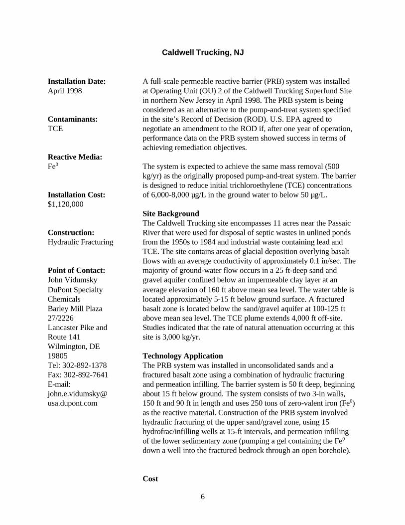
A full-scale permeable reactive barrier (PRB) system was installedat Operating Unit (OU) 2 of the Caldwell Trucking Superfund Sitein northern New Jersey in April 1998. The PRB system is beingconsidered as an alternative to the pump-and-treat system specifiedin the site’s Record of Decision (ROD). U.S. EPA agreed tonegotiate an amendment to the ROD if, after one year of operation,performance data on the PRB system showed success in terms ofachieving remediation objectives.
The system is expected to achieve the same mass removal (500kg/yr) as the originally proposed pump-and-treat system. The barrieris designed to reduce initial trichloroethylene (TCE) concentrationsof 6,000-8,000 µg/L in the ground water to below 50 µg/L.
Site BackgroundThe Caldwell Trucking site encompasses 11 acres near the PassaicRiver that were used for disposal of septic wastes in unlined pondsfrom the 1950s to 1984 and industrial waste containing lead andTCE. The site contains areas of glacial deposition overlying basaltflows with an average conductivity of approximately 0.1 in/sec. Themajority of ground-water flow occurs in a 25 ft-deep sand andgravel aquifer confined below an impermeable clay layer at anaverage elevation of 160 ft above mean sea level. The water table islocated approximately 5-15 ft below ground surface. A fracturedbasalt zone is located below the sand/gravel aquifer at 100-125 ftabove mean sea level. The TCE plume extends 4,000 ft off-site.Studies indicated that the rate of natural attenuation occurring at thissite is 3,000 kg/yr.
Technology ApplicationThe PRB system was installed in unconsolidated sands and afractured basalt zone using a combination of hydraulic fracturingand permeation infilling. The barrier system is 50 ft deep, beginningabout 15 ft below ground. The system consists of two 3-in walls,150 ft and 90 ft in length and uses 250 tons of zero-valent iron (Fe0)as the reactive material. Construction of the PRB system involvedhydraulic fracturing of the upper sand/gravel zone, using 15hydrofrac/infilling wells at 15-ft intervals, and permeation infillingof the lower sedimentary zone (pumping a gel containing the Fe0
down a well into the fractured bedrock through an open borehole).
Cost

7
The total installation cost of the PRB system (both walls) at this siteis estimated at $1,120,000—$670,000 for the 90-ft (hydrofracing)wall and $450,000 for the 150-ft (permeation infilling) wall. Thisincludes the cost of design, construction, materials, and the reactivematerial.
ResultsMonitoring wells and surface waters have been sampled at leastmonthly for volatiles and metals, and other parameters have beenmeasured. To date, the barrier has achieved 95% degradation ofTCE in the ground water, from an upgradient concentration of7,000 µg/L to a downgradient concentration of less than 400 µg/L.TCE ground-water concentrations, affected by variable ground-water flow velocities and desorption of TCE from the site soils, areexpected to reach pseudo steady-state conditions in early 1999.
Lessons Learned The low temperature and high pH at which the guar gum gel usedfor installation was formulated slowed its enzymatic degradationafter it was in place. As a solution, a pH buffer and additionalenzyme were injected. Guar breakdown then occurred and TCEreductions were observed. Otherwise, the gel has not interfered withthe barrier’s permeability nor impacted the iron's reactivity.
8
Federal Highway Administration (FHA) Facility, Lakewood, CO
Installation Date:October 1996
Contaminants:TCA; 1,1-DCE; TCE;cDCE
Reactive Media:Fe0
Installation Cost:$1,000,000
Construction:Funnel and Multiple Gate
Point of Contact:Peter McMahon U.S. Geological SurveyDenver Federal Center(MS-415)Denver, CO 80225 Tel: 303-236-4882, x286 FAX: 303-236-4912 E-mail:[email protected]
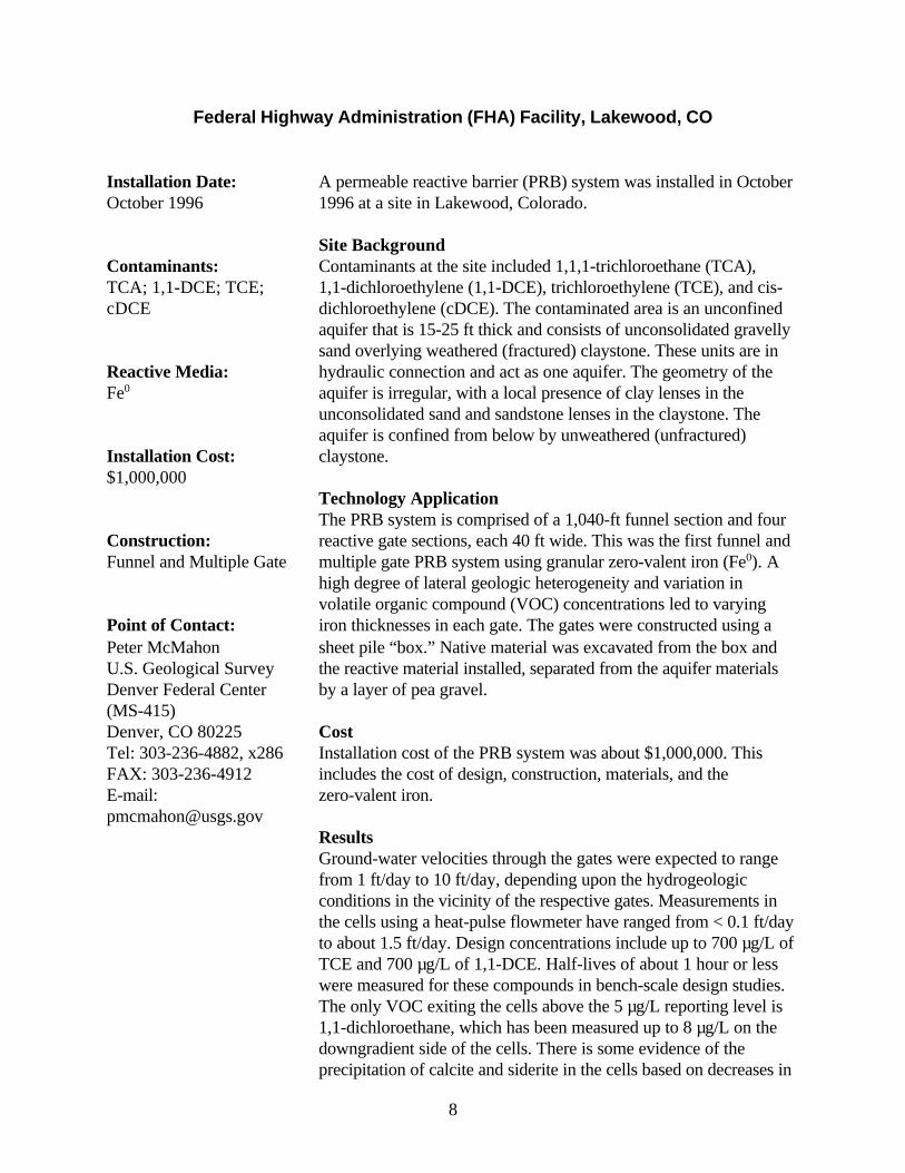
A permeable reactive barrier (PRB) system was installed in October1996 at a site in Lakewood, Colorado.
Site BackgroundContaminants at the site included 1,1,1-trichloroethane (TCA),1,1-dichloroethylene (1,1-DCE), trichloroethylene (TCE), and cis-dichloroethylene (cDCE). The contaminated area is an unconfinedaquifer that is 15-25 ft thick and consists of unconsolidated gravellysand overlying weathered (fractured) claystone. These units are inhydraulic connection and act as one aquifer. The geometry of theaquifer is irregular, with a local presence of clay lenses in theunconsolidated sand and sandstone lenses in the claystone. Theaquifer is confined from below by unweathered (unfractured)claystone.
Technology ApplicationThe PRB system is comprised of a 1,040-ft funnel section and fourreactive gate sections, each 40 ft wide. This was the first funnel andmultiple gate PRB system using granular zero-valent iron (Fe0). Ahigh degree of lateral geologic heterogeneity and variation involatile organic compound (VOC) concentrations led to varyingiron thicknesses in each gate. The gates were constructed using asheet pile “box.” Native material was excavated from the box andthe reactive material installed, separated from the aquifer materialsby a layer of pea gravel.
CostInstallation cost of the PRB system was about $1,000,000. Thisincludes the cost of design, construction, materials, and thezero-valent iron.
ResultsGround-water velocities through the gates were expected to rangefrom 1 ft/day to 10 ft/day, depending upon the hydrogeologicconditions in the vicinity of the respective gates. Measurements inthe cells using a heat-pulse flowmeter have ranged from < 0.1 ft/dayto about 1.5 ft/day. Design concentrations include up to 700 µg/L ofTCE and 700 µg/L of 1,1-DCE. Half-lives of about 1 hour or lesswere measured for these compounds in bench-scale design studies.The only VOC exiting the cells above the 5 µg/L reporting level is1,1-dichloroethane, which has been measured up to 8 µg/L on thedowngradient side of the cells. There is some evidence of theprecipitation of calcite and siderite in the cells based on decreases in
9
calcium and inorganic carbon in the treated ground water. This isestimated to result in a potential porosity loss of 0.5% of the porosityper year of operation.
Hydraulic head has increased upgradient of the barrier, with up to10 ft of head difference measured across the barrier. This increasesthe possibility for contaminated water to move around the barrier.Indeed, VOC concentrations are increasing in ground water movingaround the south end of the barrier and there is some evidence ofVOCs moving under the barrier in one location.
10
Former Drycleaning Site, Rheine, Westphalia, Germany
Installation Date:June 1998
Contaminants: PCE, 1,2-DCE
Reactive Media: Fe0, iron sponge
Design Cost: $30,000
Installation Cost: $93,000
Construction: Continuous Wall
Point of Contact:Dr. Martin Wegner Dr. Wilfried Moeller Mull & PartnerIngenieurgessellschaftmbH Osteriede 5, 30827Garbsen, Germany Tel: 49-5131-4694-55 or49-5131-4694-55Fax: 49-5131-4694-90 E-mail: [email protected]
A full-scale permeable reactive barrier (PRB) was installed at aformer drycleaning site in an urban area in Rheine, Westphalia inGermany.
Site BackgroundTetrachloroethylene (PCE) and 1,2-dichloroethylene (1,2-DCE) arethe primary contaminants of concern at the site. Initial maximumconcentrations in the plume were 20 mg/L for PCE and 0.5 mg/Lfor 1,2-DCE. The 1,640-ft-long, 820-ft-wide plume is present in aloamy sand aquifer that extends 16-33 ft below grade. The watertable is about 10 ft below the ground surface. The hydraulicconductivity varies between about 0.3 and 2.8 ft/day. The distancefrom the center of contamination to the treatment wall is about 1,300ft.
Technology ApplicationThe PRB is a continuous reactive wall that varies between 2 and 3 ftwide and is 74 ft long. The PRB was constructed by drilling a lineof overlapping 3-ft diameter boreholes which were filled withreactive material to ground-water level, and with clean soil toground surface level. The PRB uses two reactive media: 69 tons ofgranular iron (Fe0) mixed with gravel at a 1:2 volume ratio (34.5tons each of Fe0 and gravel) in 33 ft of the wall and 85 tons of ironsponge in 41 ft of the wall. A concrete-filled borehole separates thetwo segments. (Iron sponge consists of wood shavings or woodchips impregnated with hydrated iron oxide. It is used for removalof H2S in oil and gas processing operations.)
CostThe mandrel construction method was chosen because it wasdetermined to be easier and less expensive than continuous sheetpiling construction. Design costs were $30,000. Installation costsincluding construction and reactive material totaled $93,000. Anadditional $13,000 was spent on monitoring and $24,000 on theinstallation of gas measurement devices.
ResultsThis is the first continuous treatment wall in Germany and was builtas a research project with no specific target cleanup concentrations.However, the PRB has resulted in significant reduction in theconcentration of contaminants—especially PCE. The effluentconcentration of PCE from both sections of the wall is less than 100µg/L. There has been only a low level of metabolite production. No
11
vinyl chloride was observed in the affluent or effluent of the PRB.There was measurable production of hydrogen only at the verybeginning of the remediation process— simultaneous with acomplete reduction of nitrogen to ammonia. Ground-water samplesare being collected monthly.
Lessons LearnedDue to increasing microbial activity at the site of the PRB, hydrogenemission is decreasing. Nitrate now is reduced to nitrogen or N2O.The sulfate effluent concentration is decreasing due to the sulfatereduction to sulphured hydrogen.
12
Former Manufacturing Site, Fairfield, NJ
Installation Date:September 1998
Contaminants:1,1,1-TCA, PCE, TCE,DNAPL
Reactive Media:Fe0
Design Cost:$150,000
Installation Cost:$725,000
Construction:Continuous Trench
Point of Contact: Stephen Tappert VECTRE Corporation 15 Route 15 South Lafayette, NJ07848-0930 Tel: 973-383-2500 Fax: 973-579-0025 E-mail: [email protected]
A full-scale permeable reactive barrier (PRB) was installed at a sitein Fairfield, NJ, to treat chlorinated solvent contamination.
Site BackgroundThe site, a former electromechanical product manufacturing,assembly, and testing facility is currently in operation as a school. Itconsists of a single one-story slab foundation brick building andpaved parking lot covering 60% of a 2.8-acre plot of land. The siteis underlain by 15-20 ft of silty sand with some gravel, overlying alacustrine clay 10-15 ft thick. The clay unit varies in depth from15-23 ft below grade. Ground water at the site occurs under water-table conditions within the glacial sediments above bedrock, andunder confined conditions in the deeper sand aquifer. Shallowground-water flow is moving toward a nearby creek at an averagehydraulic gradient of 0.005 ft/ft. Depth-to-water in the shallow zonehas been as high as 4 ft below grade. An upward verticalground-water gradient exists between the shallow aquifer and thesilty sand unit underlying the clay, with a head difference of almost6 ft in some areas.
Environmental investigations at the site identified a plume ofchlorinated solvents, with an apparent source in the vicinity of aformer dry well and septic system. Contamination was limited to theshallow sandy aquifer. The total VOC concentration at the plumefront was approximately 4,500 µg/L. Key contaminants included1,200 µg/L trichloroethane (1,1,1-TCA), 19 µg/Ltetrachloroethylene (PCE), and 110 µg/L trichloroethylene (TCE).A pool of dense nonaqueous-phase liquid (DNAPL) was alsoidentified with significant concentrations of solvents in saturatedsoils below 15 ft. Underground utilities in place at the site includedtwo storm drains and a sewer line at 13 ft below grade.
Technology ApplicationPrior to installation of the PRB, the DNAPL pool was excavated.As a remedial measure, the excavation was partially backfilled witha 1:1 mix of zero-valent iron (Fe0) and sand. For the PRB,conventional sheet piling construction was selected as the mostreliable approach with the most predictable timeframe forcompletion. The PRB was constructed as a continuous barrierlocated ahead of the highest plume concentrations to prevent offsitemigration. The bottom portion of the barrier used a 4:1 iron/sandmixture and the upper portion of the barrier used a 3:2 iron/sandmixture. A total of 720 tons of iron were used. The final barrier was
13
127 ft wide, 25 ft deep, and 5 ft thick. After the barrier wasinstalled, the site was graded and seeded, and the parking lot wasrepaved. Construction was generally straightforward with the onlymajor problem being the below-grade sewer line that permitted alarge volume of water to enter the excavation. Constructionultimately required subaqueous excavation to complete that sectionof the wall.
CostDesign costs for the barrier, including a licensing fee, were$150,000. Installation costs (which include construction, materials,and reactive media) totaled $725,000.
ResultsCleanup goals for chlorinated solvents at the site were New JerseyGround Water Quality Criteria: 1 µg/L for PCE, 1 µg/L for TCE,and 30 µg/L for 1,1,1-TCA. Monitoring wells were installedupgradient, downgradient, and within the PRB and samples werecollected one month after installation. At that time, VOCconcentrations at the center of the plume decreased to 33 µg/Lwithin the PRB. Subsequent quarterly sampling results showed anincrease in pH from approximately 6.5 to 9.5, a change in Eh from-50 mv to -400 mv, and concentrations of VOCs at or near detectionlimits in the middle of the wall. Future sampling plans includequarterly monitoring of selected wells for two years, then continuedmonitoring with reduced frequency after that.
Lessons Learned Detailed knowledge of the site and detailed planning were critical tomaking this technology work. Also, it was important to get the stateagency on the team early to expedite the project.
14
Industrial Site, Belfast, Northern Ireland
Installation Date:December 1995
Contaminants:TCE, 1,2-cDCE
Reactive Media:Fe0
Installation Cost:$375,000
Construction:Slurry Wall Funnel In Situ Reaction Vessel
Point of Contact:Stephanie O’Hannesin EnviroMetalTechnologies, Inc. 42 Arrow Road Guelph, OntarioN1K 1S6 CanadaTel: 519-824-0432 Fax: 519-763-2378 E-mail:[email protected]
A full-scale field test of a permeable reactive barrier (PRB) systemwas conducted at an industrial facility in Belfast, Ireland.
Site BackgroundA circular in situ reaction vessel filled with iron was installed to adepth of about 40 ft in December 1995, to treat up to 390 mg/L oftrichloroethylene (TCE) and related breakdown products. Previousowners of the site had used chlorinated solvents whilemanufacturing electronic components. Years of spillages resulted inan intense but localized plume close to the current site boundary.
The TCE plume at this site is located in an area characterized by athick deposit of till (up to 78 ft) underlain by Mercia mudstones. Thetill has silt, sand, and gravel lenses that allow contaminants tomigrate from the source; however, migration is constrained by thespecific orientation of the permeable lenses that contain discrete clayor clayey silt lenses. The depth of the barrier was chosen to interceptthe horizon of low permeability that is present at a depth of around33 ft. The site is characterized as having a water table approximately20 ft below ground surface, and an underlying aquifer about 40 ft indepth.
Technology ApplicationTwo 100-ft bentonite cement slurry walls directed water to the inletof the steel reaction vessel, which was 4 ft in diameter and containeda 16-ft vertical thickness of zero-valent iron (Fe0). Ground waterflowed by gravity through the iron zone and discharged through apiped outlet on the downgradient side of the slurry wall. The vesselwas equipped with a manhole to access the top of the iron zone, inthe event that periodic scarification of the iron surface proved accesswas necessary. The system was designed to provide residence timeof about 5 days.
CostThe total cost of the system, including slurry walls, granular iron,reaction vessel, and engineering was about $375,000.
ResultsThe system was designed to meet ground-water-quality criteria of500 µg/L for TCE, which apply to ground water beneath industrialland slated for redevelopment. Flow rates through the reactor havevaried substantially since its installation, but data have shown anoverall 99.7% reduction in TCE and cis-1,2-dichloroethylene
15
(cDCE) levels through the reaction vessel. Both increased anddecreased levels of cDCE resulting from reductive dehalogenationhave been identified. TCE levels in the system have been decreasingin the effluent sample ports. Only low levels (in the range of 100µg/L) of cDCE have been detected. Vinyl chloride, a commonbreakdown product of this process, has not appeared in appreciablequantities.
16
Industrial Site, Coffeyville, KS
Installation Date:January 1996
Contaminants:TCE, 1,1,1-TCA
Reactive Media:Fe0
Installation Cost:$400,000
Construction:Funnel and Gate
Point of Contact:Greg SomermeyerSECOR International,Inc.4700 McMurry DriveSuite 101Fort Collins, CO 80525Tel: 970-226-4040Fax: 970-226-4099
This permeable reactive barrier (PRB) system was installed at theproperty boundary of an industrial site in Coffeyville, KS, inJanuary 1996.
Site BackgroundThe site covers about 200 acres and is hydrologically andgeochemically complex. Contaminants include trichloroethylene(TCE) and 1,1,1-trichloroethane (TCA). Prior releases at this sitehad generated a dissolved plume approximately 875 yds longcontaminated with 400 µg/L of TCE and 100 µg/L of 1,1,1-TCA.Contaminant transport occurred to the greatest lateral extent in abasal sand and gravel unit just above shale bedrock, which liesabout 30 ft beneath the site. There is nearby public use of shallowground water necessitating measures to prevent additional off sitemigration.
Technology ApplicationThe PRB system uses a funnel-and-gate configuration to directground water through a single, permeable treatment gate that is 20 ftlong and 3 ft thick. The funnel section of the system consists of two490-ft soil-bentonite slurry walls on either side of the treatment gate.Zero-valent iron (Fe0) is used as the reactive material. The treatmentwall contains 70 tons of the iron. A low ground-water flow velocityof 0.2 ft/day permitted the use of this relatively high funnel-to-gateratio. The system is installed to a depth of 30 ft in a basal alluvialaquifer.
CostThe installation cost for the system, including slurry walls, treatmentgate, and granular iron, was approximately $400,000.
ResultsNo determinations of ground-water velocity through the systemhave been made to date. Concentrations in the iron zone are belowMaximum Contaminant Levels (MCLs).
17
Industrial Site, NY
Installation Date: December 1997
Contaminants: TCE, cDCE, VC
Reactive Media: Fe0
Installation Cost: $797,000
Construction: Continuous Trench
Point of Contact:Diane Clark Stearns & Wheler, LLC One Remington Park Dr.Cazenovia, NY 13035 Tel: 315-655-8161 Fax: 315-655-4180 E-mail: [email protected]
A full-scale permeable reactive barrier (PRB) was installed at aformer plating facility in Central New York in December 1997.
Site BackgroundTrichloroethylene (TCE), cis-1,2-dichloroethylene (cDCE), andvinyl chloride (VC) are the primary contaminants of concern at thisfacility. Initial concentrations ranged from 200-1,280 µg/L for TCE,300-1,800 µg/L for cDCE, and 26-53 µg/L for VC. Total volatileorganic compounds (VOC) concentrations ranged from 300 µg/L-900 µg/L. The goal of this project is to clean the site to New Yorkground-water standards, 5 µg/L for TCE, 5 µg/L for cDCE, and 2µg/L for VC.
The 370-ft plume is present in a sand and gravel aquifer that extendsfrom 4-21 ft below grade, and the water table is located 4-5 ft belowground surface. Based on the results of slug tests, the hydraulicconductivity of the material in the aquifer ranges from about 16 to230 ft/day.
Technology ApplicationThe PRB uses 742 tons of bulk granular zero-valent iron (Fe0) forreductive dehalogenation of chlorinated aliphatic compounds. It wasconstructed as a continuous wall, measuring 1 ft thick and 18 ftdeep, across the entire width of the plume. An additional 1-ft-thickcontinuous wall was placed 10 ft upgradient of the longer wall andin the portion of the plume with the highest concentrations of totalVOCs to provide additional residence time in the reactive iron.
The system was installed with continuous trenching equipment thatuses a large cutting chain excavator combined with a trench box andloading hopper. To construct the barrier, the cutting chain removedthe native soil along the trench line. As the machine advanced alongthe trench line, the granular iron was lowered through the hopperand trench box into the excavated trench. During this process, thetrenching equipment proved to move faster than the rate at whichthe iron settled into the excavated trench. As a result, the top 2 ft ofthe trench had to be backfilled with a backhoe to reach the 18-ftdepth.
A 3-ft bench was excavated prior to the use of the trenchingequipment, allowing the wall to be installed to the maximum depthof the clay layer, which was 21 ft below normal site grade. Thespoils removed from the trench were then spread on the surface of
18
the bench on the upgradient side of the iron. Finally, the spoils werecovered by backfill of the clean soil excavated for the bench,amounting to a minimum of 2 ft of clean soil as cover.
CostA predesign study determined that a continuous permeable reactivebarrier was more cost-effective than a funnel-and-gate system at thissite. Installation costs for the full-scale system were $797,000. Thisincludes construction, materials, and the cost of the reactive material.In addition, it includes the cost of site improvements allowing accessby the trenching equipment. Design cost for this system is notavailable. Because several issues that would not be required forother installations were included in this system's design cost, sitemanagers indicate that it probably would not be applicable, as far asscale-up, to other sites.
ResultsRecent sampling results have indicated upgradient concentrations of2,200 µg/L TCE, 4,900 µg/L 1,2-DCE, and 260 µg/L VC.Downgradient results showed only 5 µg/L 1,2-DCE and 23 µg/LVC. Ground-water samples will be collected on a quarterly basis fora total of 5 years.
Lessons Learned At this particular site, construction of a continuous trench systemwas more cost-effective than a funnel-and-gate system. This optionalso required the shortest construction period, minimizing disruptionto the landowner. In addition, site managers were able to managetrench spoils onsite, instead of having to dispose of them offsite.Spoils were spread in the benched area and capped with a minimum2 ft of top soil, which had been stripped off prior to construction andstockpiled.
19
Industrial Site, SC
Installation Date:November 1997
Contaminants:TCE, cDCE, VC
Reactive Media:Fe0
Design Cost:$50,000
Installation Cost:$350,000
Construction:Continuous Trench
Point of Contact:Steven SchroederRMT, Inc.100 Verdae BoulevardP.O. Box 16778Greenville, SC29606-6778Tel: 864-281-0030Fax: 864-287-0288E-mail:[email protected]
Phase 1 of a full-scale permeable reactive barrier (PRB) wasinstalled at a former industrial site in Manning, SC, in November1997.
Site BackgroundTrichloroethylene (TCE), cis-1,2-dichloroethylene (cDCE), andvinyl chloride (VC) have been detected in two aquifers that underliethe site at concentrations of 25 mg/L, 3.5 mg/L, and 0.9 mg/L,respectively. TCE concentrations in the lower of the twocontaminated aquifers are generally one order of magnitude lessthan those in the upper aquifer.
The upper aquifer is 5-15 ft below ground surface (bgs). It iscomposed primarily of sandy to silty fill material with a hydraulicconductivity of 2 ft/day. A clay unit forms the lower boundary ofthis aquifer. The intermediate aquifer (18-27 ft bgs) is composed offine silt laminae and very fine sand layers within the clay unit andhas a hydraulic conductivity of 2.6 ft/day. The lower portion of thisclay unit forms a boundary between the intermediate and loweraquifers. Monitoring wells did not detect any volatile organiccompounds (VOCs) in the lower aquifer.
Technology ApplicationThe PRB was installed to the base of the intermediate aquifer. It is a1-ft-wide continuous trench composed of 50% sand and 50% zero-valent iron (Fe0) by volume in the form of iron filings. The 400 tonsof Fe0 was homogeneously distributed throughout the sand usingcement-mixing equipment. A one-pass trenching technique wasused from a surface bench 4-6 ft bgs. This surface bench allowedthe trenching equipment to reach the final depth of 29 ft bgs. Phase1 of the installation called for a 325-ft section to address the highestconcentrations of VOCs and mitigate suspected off-site migration.Phase I construction—including mobilization, benching, installation,and demobilization—was completed in 4 weeks.
CostDesign for this PRB system was $50,000. The total installation costfor both phases will be approximately $350,000. This includesconstruction, materials, and the cost of the reactive media.
Results
20
Cleanup goals for the site are 0.005 mg/L for TCE, 0.070 mg/L forcDCE, and 0.002 mg/L for VC. After the initial 9 months of systemoperation, positive indicators for dechlorination were measured atdowngradient monitoring wells for both VOC concentrations andindicator compounds (pH, eH, chloride). However, due to the slowrate of ground-water flow and the fact that VOCs were presentdowngradient of the wall at installation, performance evaluationscontinue. Construction of Phase 2 will extend the wall to a totallength of 1,000 ft to treat the entire contaminant plume.
Minor problems were encountered at the start of Phase 1 installation,with some material cave-in occurring at the top 3-4 ft of the trenchsidewalls. This problem was alleviated by reconfiguring the locationof the feed hopper on top of the boot and by adding steel plates tothe top portion of the boot, to improve material flow. Installationthrough the two aquifers has affected ground-water flow in thevicinity of the treatment wall. By providing a greater connectionbetween the two aquifers, ground-water velocities have beenreduced and ground-water flowpaths modified slightly. Thereduction in ground-water velocities and modified flowpaths shouldnot affect the capability of the treatment wall to intercept andadequately treat VOCs at the site. Increased residence time fortreatment will improve the long term treatment efficacy.
Modifications to the ground-water monitoring schedule were alsonecessary to take into account differences in ground-water flowrates. Sampling upgradient and downgradient of the wall isconducted on a quarterly basis. Semi-annual sampling is anticipatedin the future.
Lessons LearnedCompared with other methods, continuous trenching provided cost-effective installation and a high degree of confidence that materialswould be placed according to the design, to create a continuoustreatment wall with equal distribution of the Fe0.
Because of the reduced ground-water flow velocity at the site, moretime than originally estimated will be required to complete an initialflushing of VOCs in downgradient ground water. This site mayrequire 18-24 months to complete dechlorination sufficient toachieve cleanup levels.
Expectations and data collection efforts relative to performance willbe planned to accommodate a relatively long initial period ofoperation and monitoring.

21
22
Intersil Semiconductor Site, Sunnyvale, CA
Installation Date: February 1995
Contaminants: TCE, cDCE, VC,Freon 113®
Reactive Media: Fe0
Installation Cost: $1,000,000
Construction: Funnel and Gate
Point of Contact:Carol Yamane Geomatrix Consultants,Inc. 100 Pine Street San Francisco, CA94111 Tel: 415-434-9400 Fax: 415-434-1365 E-mail: [email protected]
In January 1995, after being approved by the California RegionalWater Quality Control Board, a permeable reactive barrier (PRB)was installed at the Intersil Semiconductor Site in Sunnyvale, CA.
Site BackgroundIntersil had manufactured semiconductors at the site from the early1970s until 1983. In 1972, the company had installed a concrete,epoxy-lined, in-ground system at the facility to neutralize acid inwastewater before discharge to a sanitary sewer. Soil andground-water contamination from halogenated volatile organiccompounds (VOCs) was identified near the neutralization holdingtank site after it was removed early in 1987. Initial concentrations ofcontaminants were 50-200 µg/L of trichloroethylene (TCE),450-1,000 µg/L of cis-1,2,-dichloroethylene (cDCE), 100-500 µg/Lof vinyl chloride (VC), and 20-60 µg/L of Freon 113®.Ground-water extraction and treatment, using an air stripper, beganlate in 1987. The in situ PRB system replaced the existingpump-and-treat system which was being maintained at a significantcost. The original system has been removed and the property hasbeen restored to full economic use. The monitoring wells provideaccess to the in situ system for periodic monitoring compliance.
The contaminated area is in a semiconfined aquifer that is 2-4 ftthick. It is composed of interfingering zones of silty, fine-grainedsand, fine- to medium-grained sand, and gravelly sand. Thegeometry of the aquifer is irregular, with a local presence of claylenses. The aquifer is mostly confined by an upper silty-clay andclay layer, which ranges from 9-12 ft thick, and by a lower aquitardof clay and silty clay, which is about 65 ft thick.
Technology ApplicationThe physical constraints of the site helped determine the geometryof the PRB and the construction technique used. To addresshistorically changing ground-water flow directions, lowpermeability walls were installed upgradient and perpendicular tothe PRB to contain affected ground water onsite prior to flowthrough the barrier. The treatment zone is sandwiched betweenpermeable gravel layers to evenly distribute flow through the zone.The barrier itself is 4 ft wide, 36 ft long, and 20 ft deep. It ischarged with 220 tons of granular iron (Fe0) to a depth of about 11ft. A low, permeable “wing” that extends perpendicular from thetreatment wall to about 20 ft downgradient was installed to reduce
23
the impact on ground-water velocity through the wall due tovariations in regional flow direction.
CostInstallation cost for the in situ PRB system, including the slurrywalls used to direct ground water toward the permeable reactivebarrier, was $1,000,000. This includes the cost of construction,materials, and the iron. Design cost for this system is not available.
ResultsThe cleanup goal established for the site is to reduce contaminantconcentrations to levels below the Maximum Contaminant Level(MCL) set by the State of California and Primary Drinking WaterStandards—5 µg/L for TCE, 6 µg/L for cDCE, 0.5 µg/L for VC,and 1,200 µg/L for Freon 113®. Since installation, VOCconcentrations have been reported below cleanup goals frommonitoring wells located within the iron wall. While seasonalhydraulic mounding has been observed above the PRB, it is notexpected to affect long-term performance of the barrier. Affectedground water is contained onsite when mounding is present. Whenthe mounding dissipates, ground water again flows through thebarrier and is treated.
Lessons Learned In addition to helping distribute flow through the PRB, the peagravel zone placed upgradient of the PRB has resulted inprecipitation of naturally occurring minerals and partial treatment oftarget chemicals upgradient of the iron treatment zone. Some mixingof the iron into the pea gravel zone is likely to have occurred duringconstruction and resulted in chemical conditions favorable for somemineral precipitation (for example, higher pH, lower redox potentialthan ambient ground water). This is evidenced by inorganicchemistry data from wells within the pea gravel. While sitemanagers did not anticipate this benefit, the result is expected toextend the life of the treatment zone relative to the potential negativeeffects of mineral precipitation.
24
Kansas City Plant, Kansas City, MO
Installation Date: April 1998
Contaminants: 1,2-DCE, VC
Reactive Media: Fe0
Design Cost: $200,000
Installation Cost: $1,300,000
Construction: Continuous Trench
Point of Contact: Paul Dieckmann AlliedSignal FM&T 2000 East 95th St. (P.O. Box 419159) Kansas City, MO64141-6159 Tel: 816-997-2335 Fax: 816-997-7361 E-mail:[email protected]
A permeable reactive barrier (PRB) was installed in April 1998 atthe U.S. Department of Energy's Kansas City Plant in Kansas City,MO.
Site BackgroundContaminants of concern include 1,2-dichloroethylene (1,2-DCE)and vinyl chloride (VC). Maximum initial concentrationsencountered at the site were 1,377 µg/L of 1,2-DCE and 291 µg/Lof VC.
The Kansas City Plant site is underlain by alluvial sediments thatrange from 20-33 ft in thickness. Lower alluvial sediments arecharacterized by low plasticity clays that overlie basal gravels. Thealluvial sediments are underlain by bedrock shales. The basal gravelis the most permeable unit and acts as a semi-confined aquifer. Thehydraulic conductivity of the basal gravel is 34 ft/day, while thehydraulic conductivity of the overlying clay unit is 0.75 ft/day.
Technology ApplicationThe PRB was constructed as a continuous trench measuring 130 ftlong. Sheet piles were driven into bedrock to support the side walls.The resulting excavation was 6 ft wide. The first 6 ft of the trenchabove bedrock was filled with 100% zero-valent iron (Fe0). Theremainder of the trench was filled with 2 ft of Fe0 and 4 ft of sand.These differing thicknesses were used to compensate for theincreased flow-through thickness required for the basal gravel unit.Approximately 8,320 cubic feet of reactive iron was used in thepermeable barrier.
CostDesign costs were approximately $200,000. Design costs includedpre-design site characterization done to obtain additional chemical,hydrological, and geotechnical data. Installation costs were$1,300,000. This includes construction, materials, the reactivematerial, and hazardous waste transportation and disposal.
ResultsCleanup goals for the site are Maximum Contaminant Levels(MCLs) as defined in 40 CFR 141.2 and listed in 40 CFR 141.61(a)and 40 CFR 264.94. (70 µg/L for 1,2-DCE and 2 µg/L for VC.)The VOC plume is predominant in the basal gravel unit. A numberof monitoring wells have been installed. Upper completion wells arescreened in the saturated clay. The clay soil extends from the ground
25
surface to a depth of approximately 25 ft. Lower completion wellsare screened in the basal gravel formation which varies in thicknessfrom about 3-5 ft and overlays the bedrock (shale). Lowercompletion wells were installed at the upgradient face, center, anddowngradient face of the wall at three locations. Sidegradient wellswere installed as well to confirm that the contamination is not goingaround the wall. Results of a January 16, 1999, sampling eventindicate that all compliance wells are below MCLs.
Plans call for investigative fieldwork to be conducted at the PRB inFebruary 1999. This will include subjecting a number of the wells tocolloidal borescope measurements, heat-pulse flow metermeasurements, and enhanced (nitrogen pressure) single well testingin order to address the following questions:
Can flow rates and directions within an iron wall be adequatelydetermined?
Are there significant flow contrasts within the treatment area? Can the enhanced single-well testing procedure adequately
determine permeability contrasts within the treatment zone? How do the borescope, heat-pulse meter, and enhanced
single-well testing procedures compare with respect to ease-of-use and precision of measurement?
Lessons Learned The two main advantages for choosing the continuous permeablewall design were predictability and economics.
A continuous permeable wall impacts the existing ground-waterflow system less than some other designs. Modeling (predicting)“changes” in flow directions and velocities were not required forthis design as would have been for a funnel-and-gate system. Theupgradient horizontal extent of the plume and ground-water levelsare expected to experience little change.
The cost and time required for constructing a continuous permeablereactive wall was estimated to be less than for constructing a seriesof impermeable wall and gate sections. The continuous wall wasexpected to be constructed with a one-pass deep trenching machine.However, the contractor had difficulties with the trenching machine,which may have been due to the heavy, wet clay. The problemsencountered resulted in utilization of conventional sheet pileconstruction of the permeable wall. This should actually benefit thelong-term performance. For example, there was better opportunityduring the installation process to verify intimate contact of ironplacement with the bedrock surface; additional wall thickness was
26
created by the use of “Z” piles; and uniform, continuous placementof iron was visually verified.
27
Lowry Air Force Base, CO
Installation Date:December 1995
Contaminants:TCE
Reactive Media:Fe0
Installation Cost:$530,000
Construction:Funnel and Gate
Point of Contact:William A. GallantVersar, Inc.11990 Grant StreetSuite 500Northglenn, CO 80233Tel: 303-452-5700Fax: 303-452-2336E-mail:[email protected]
A demonstration project of a permeable reactive barrier (PRB) toremediate ground water contaminated with chlorinatedhydrocarbons was initiated at Lowry Air Force Base, CO.
Site BackgroundContamination at Lowry is a result of various base activitiesgenerating contaminants that were transferred to local ground watervia storm drains, septic tanks, or direct infiltration. The totalchlorinated hydrocarbon concentration was approximately 1,400µg/L, primarily consisting of trichloroethylene (TCE).
The Lowry site is underlain by unconsolidated alluvial deposits andartificial fill that is approximately 18 ft thick. These surficial depositsoverlie bedrock consisting of silty claystones and sandy siltstones.The local water table aquifer is approximately 9 ft below groundsurface (bgs) and saturates alluvial material as well as the upper 10 ftof underlying bedrock in places. Local ground-water flow patternsare partly controlled by paleochannels eroded into the underlyingbedrock. Hydraulic conductivity for the site averages 35 ft/day, andthe average ground-water velocity is 1 ft/day.
Technology ApplicationThe funnel-and-gate system constructed consists of a 10-ft-wide and5-ft-thick reactive wall composed of 100% granular, zero-valent iron(Fe0) and two 14-ft sheet piling walls that were installed to a depthof 17 ft.
CostThe total installation cost for the system was approximately$530,000. This includes design, construction, materials, and thereactive material.
ResultsThirty-four wells located within and proximate to the wall wereused to monitor the system’s performance. Seven sets of sampleswere taken from December 1995 through June 1996. Data analysisindicates that a first-order, abiotic reaction involving reductivedehalogenation is taking place within the reactive iron wall.Chlorinated hydrocarbons are being completely degraded within thefirst foot of the wall. After 18 hours residence time (2 ft into thewall), all analytes degrade to their respective analytical quantitationlimits. In addition, intermediate breakdown products producedduring the process are also degraded. The wall was resampled in

28
May 1997 with similar results. Since the PRB was designed andbuilt as a short-term solution, there are no plans to continue themonitoring. A slurry wall containment area was constructed inOctober 1997 30-50 ft upgradient of the PRB as part of a newsource-area remedial system.
29
U.S. Coast Guard Support Center, Elizabeth City, NC
Installation Date:June 1996
Contaminants: Cr+6, TCE
Reactive Media: Fe0
Installation Cost: $500,000
Construction:Continuous Trench
Point of Contact:Robert W. Puls U.S. EPA/National Risk Management Research Laboratory P.O. Box 1198 Ada, OK 74820 Tel: 580-436-8543 Fax: 580-436-8706 E-mail:[email protected]
A full-scale demonstration of a permeable reactive barrier (PRB) toremediate ground water contaminated with chromium andchlorinated organic compounds was initiated at the U.S. CoastGuard Support Center site in Elizabeth City, NC, in 1995.
Site BackgroundThe primary contaminants of concern are hexavalent chromium(Cr+6) and trichloroethylene (TCE). Initial maximum concentrationswere more than 4,320 µg/L for TCE and more than 3,430 µg/L forCr+6. The contaminant plume was estimated to cover a 34,000-ft2
area. The plume is adjacent to a former electroplating shop thatoperated for more than 30 years prior to 1984 when operationsceased. Ground water begins approximately 6 ft below groundsurface, and a highly conductive zone is located 16-20 ft below thesurface. This layer coincides with the highest aqueousconcentrations of chromium and chlorinated organic compoundsfound on the site. A low-conductivity layer—clayey, fine sand tosilty clay—is located at a depth of about 22 ft. This layer acts as anaquitard to the contaminants located immediately above.
Technology ApplicationA continuous wall composed of 100% zero-valent iron (Fe0) wasinstalled in June 1996 using a trencher that was capable of installingthe granular iron to a depth of 24 ft. The continuous trenchingequipment used for the installation has a large cutting chainexcavator system to remove native soil combined with a trench boxand loading hopper to emplace the iron.
The trenched wall is approximately 2 ft thick and about 150 ft long.The wall begins about 3 ft below ground surface and consists ofabout 450 tons of granular iron.
CostThe total installation cost was $500,000. This includes the cost ofdesign, construction, materials, and the iron, which cost about$175,000.
ResultsThe wall was designed to meet cleanup goal concentrations of 0.05mg/L of Cr+6 and 5 µg/L of TCE. Performance monitoring has beenconducted on a quarterly basis since November 1996. In addition to2-in PVC compliance wells, the wall is monitored using a series ofmultilevel sampling (MLS) ports to monitor the geochemicalmechanisms occurring in the barrier and in the downgradientaquifer. Sampling results for chromium indicate that all chromiumhas been removed from the ground water within the first 6 inches ofthe wall as expected. No chromium has been detected downgradient
30
of the wall either in the MLS ports or in the compliance wellslocated immediately behind the wall. Results thus far indicate thatthe barrier is successfully reducing TCE, c-DCE, and vinyl chlorideconcentrations to less than MCL levels for the vast majority of themonitored portions of the wall. Of 29 downgradient MLS ports,MCLs for TCE and vinyl chloride are exceeded in 1 and 3 ports,respectively. TCE concentrations are generally below 5 µg/L withinthe wall, but exceed 50 µg/L at the lowest depth. There are someindications that the TCE plume may have dipped lower in this partof the aquifer following wall installation. The slight elevationbeyond target levels for vinyl chloride seen in the MLS ports are notreflected in adjoining compliance wells. Downgradient vinylchloride concentrations in the MLS ports have declined with time.Nowhere do c-DCE concentrations exceed regulatory limits.
Numerous vertical and angle cores also have been collected at thesite to examine changes to the iron surface and to evaluate theformation of secondary precipitates which may affect wallperformance over time. These cores continue to be studied.
Lessons Learned Researchers are investigating the possibility that the TCE plume hasdipped lower in the aquifer after the wall was installed and is nowmoving under the wall. A significant amount of recharge occurredinto the reaction zone following installation due to removal of theconcrete parking lot covering the site. This recharge may havedriven the plume deeper than had previously been observedallowing some of the plume to move under the wall. Interestingly,there is still significant treatment below the wall where no ironresides.
Based on limited preliminary electrical conductivity profiles, thewall is approximately 19-21 in thick, compared to the designthickness of 23 in. Some minor vertical discontinuities wereobserved in the conductivity data and have been confirmed withcoring. These small gaps are probably due to bridging within thetrencher hopper during iron emplacement.
31
Area 5, Dover Air Force Base (AFB), DE
Installation Date:January 1998
Contaminants:PCE, TCE, DCE
Reactive Media:Fe0
Installation Cost:$800,000
Construction:Funnel and Gate
Point of Contact:1Lt. Dennis O'SullivanAir Force ResearchLaboratory Airbase &EnvironmentalTechnology Division(AFRL/MLQ)139 Barnes DriveSuite 2Tyndall Air Force Base,Florida 32403-5323 Tel: 850-283-6239Fax: 850-283-6064E-mail:dennis_o’[email protected]
A pilot-scale field demonstration of a permeable reactive barrier(PRB) is being conducted at the Area 5 site at Dover AFB, DE. Thedemonstration is funded by the Strategic Environmental Researchand Development Program (SERDP).
Site BackgroundThe Dover site is contaminated with perchloroethylene (PCE),trichloroethylene (TCE), and dichloroethylene (DCE). Themaximum concentrations encountered during site characterizationwere 5,617 µg/L of PCE, 549 µg/L of TCE, and 529 µg/L of DCE.Area 5 lies within the Atlantic Coastal Plain PhysiographicProvince, consisting of Cretaceous to Recent sedimentary depositsof gravel, sand, silt, clay, limestone, marl, and chalk dipping to thesoutheast. Ground water is located 5-15 ft below ground surface.The clay aquitard is located 40-45 ft below the surface. Thehydraulic conductivity values used for design of the permeablebarrier were based on an aquifer conductivity range of 10-50 ft/day.
Technology ApplicationMajor objectives of the demonstration include comparing tworeactive media schemes and examining innovative emplacementtechniques designed to reduce the cost of construction for PRBsystems. The funnel-and-gate system, installed in January 1998,consists of two gates that are 8 ft wide and 45 ft deep. One gate isfilled with pure, zero-valent iron (Fe0) filings with a 10% iron/sandpretreatment zone to stabilize flow and remove dissolved oxygen.The second gate also is filled with iron, but it is preceded by a 10%pyrite/sand mixture. The mixture serves to moderate the pH of thereactive bed, thereby decreasing the precipitates formed.
The gates were constructed with 8-ft-diameter caissons that wereremoved after reactive media emplacement. The funnel sectionswere built using Waterloo interlocking sheet piling driven to the45-ft depth and keyed into the underlying clay aquitard.
CostThe total installation cost for the system was $800,000. Thisincludes the cost of design, construction, materials, and the reactivematerial.
Results
32
Results of the demonstration are unknown at this time. Twocomprehensive monitoring events are planned for July andDecember 1998. The demonstration is being used to validate thedocument “Design Guidance for Application of Permeable Barriersto Remediate Dissolved Chlorinated Solvents,” developed withinput from state and federal regulators and published in February1997. At the completion of the project (approximately December1998), the guidance document will be updated to reflect lessonslearned.
33
Borden Aquifer, Ontario, Canada
Installation Date:1991
Contaminants:TCE, PCE
Reactive Media:Fe0
Installation Cost:$30,000 (not includingFe0 and labor)
Construction:Continuous Trench
Point of Contact:Stephanie F. O’HannesinWaterloo Centre forGroundwater ResearchUniversity of WaterlooWaterloo, OntarioN2L 3G1 CanadaTel: 519-885-1211 x3159 Fax: 519-763-2378 E-mail: [email protected]
A pilot-scale demonstration of a permeable reactive barrier (PRB) toremediate ground water contaminated with trichloroethylene (TCE)and perchloroethylene (PCE) was conducted at the Canadian ForcesBase in Borden, Ontario, Canada. The PRB was installed in 1991.
Site BackgroundContamination was the result of a previous site study to determinethe dissolution characteristics of a mixed non-aqueous fluid. Thecontaminant plume was about 6.5 ft wide and 3.3 ft thick. Initialconcentrations were 250,000 µg/L TCE and 43,000 µg/L PCE. Theplume source was located about 13 ft below ground surface (bgs)and 3.3 ft below the water table.
The contaminated surficial aquifer is composed of medium-finesand. Its lower boundary is a thick clay deposit located 30 ft belowthe surface. The upper boundary of the aquifer varies between 6.5 ftand 10 ft bgs. Hydraulic conductivity for the surficial sand aquifer is20.5 ft/day.
Technology ApplicationReactive material was installed using sealable joint sheet piling 18 ftdowngradient from the source. Individual piles were interlocked tocreate a rectangular cell normal to ground-water flow direction thatwas 18 ft long, 5 ft wide, and 32 ft high. The pilings were thendriven as a unit to a depth of 32 ft using a hydraulic vibratory driversuspended by a crane. The joints were sealed with a bentonite-basedsealant, and the water table was lowered below the depth ofexcavation. The cell was then excavated and the native material wasreplaced with a mix of 22% (by weight) zero-valent granular iron(Fe0) and 78% coarse sand from 12.4-20 ft bgs. This mixture had ahydraulic conductivity of 124 ft/day. After emplacement of themixture, the sheet pilings were removed.
CostThe cost for installation, exclusive of the cost of reactive iron andlabor, was $30,000. The reactive material and the labor weredonated.
34
ResultsA total of 348 monitoring wells were installed upgradient anddowngradient from the wall, as well as within the reactive material.Concentration distributions were monitored over a period of fiveyears. The PRB reduced TCE concentrations by 90% and PCEconcentrations by 86%. No vinyl chloride was detected in thesamples. The low amounts of calcium carbonate precipitate detectedin the wall after five years suggests that the wall’s performanceshould persist for at least another five years. Since the residualsource was remediated using permanganate flushing, there are noplans for additional sampling.
35
Cape Canaveral Air Station, FL
Installation Date:October-November 1997
Contaminants:TCE, DCE, VC
Reactive Media:Fe0
Design Cost:$292,000 (for twobarriers)
Installation Cost:$279,000 (Mandrel) $238,000 (Jet-AssistedGrout)
Construction:Continuous Walls with Overlapping Panels
Point of Contact:Maj. Edward MarchandU.S. Air Force Center forEnvironmentalExcellence3207 North RoadBrooks AFB, TX 78235Tel.: 210-536-4364Fax: 210-536-4330 E-mail:[email protected]
Side-by-side, pilot-scale demonstrations of two emplacementtechniques for permeable reactive barriers (PRBs) are beingconducted at the industrial area of Cape Canaveral Air Station, FL.
Site BackgroundThe site is contaminated with 90 mg/L of trichloroethylene (TCE), 7mg/L of vinyl chloride (VC), and 170 mg/L of dichloroethylene(DCE). The water table at the site is about 5 ft below groundsurface. Ground-water flow is in the range of 0.1-0.5 ft/day andchanges with depth.
Technology ApplicationA major objective of the demonstration was to compare the twoemplacement methods. Both wall systems included a 50-ft mainwall followed by 10-ft wall placed 4 ft downgradient from it and athird 10-ft wall placed 4 ft downgradient of the second. Thisprovided a total target length of 70 linear ft for each technique. Inthe first installation, a hollow mandrel, or vibrated beam, created avoid that is 4 in thick, about 45 ft deep, and 32 in long for eachpanel of the wall. A vibratory hammer drove the beam to therequired depth. The void was filled with the reactive materialthrough a chute at the top of the mandrel. About 98 tons of 100%zero-valent iron (Fe0) was used to construct the wall, and adjacentpanels were overlapped to provide continuity in the wall. In thesecond installation, high-pressure water jets, guided by a 36-inI-beam, were used in addition to the water to create the void foreach wall panel. A vibratory hammer was used to drive the beam todepth. The void was filled with a slurry made by mixing Fe0 withguar gum and a binder. About 107 tons of Fe0 was used for thisemplacement. As in the first installation, adjacent wall panels wereoverlapped to provide continuity.
CostTotal installation cost for the two barriers at this site was $809,000.This includes design, construction, materials, and the reactive media.The design cost for both walls totaled $292,000. Mobilization anddemobilization, construction, materials, and the reactive material forthe mandrel system was $279,000. Mobilization and demobilization,construction, materials, and the reactive material for the jet-assistedgrout system was $238,000.
Results
36
Results of the demonstration are unknown at this time. Dedicated insitu flow sensors and ground-water monitoring wells were installedafter construction of the walls to track performance.
Quarterly monitoring is scheduled to continue until November 1998,and a report of demonstration results is expected to be issued in1999.
37
Industrial Site, NY
Installation Date:May 1995
Contaminants:TCE, cDCE, VC
Reactive Media:Fe0
Installation Cost:$250,000
Construction:Funnel and Gate
Point of Contact:Diane Clark Stearns & Wheler One Remington ParkDrive Cazenovia, NY 13035 Tel: 315-655-8161 Fax: 315-655-4180 E-mail:[email protected]
A pilot-scale, in situ funnel-and-gate system using metal-enhancedreductive dehalogenation was installed at an industrial facility inNew York in May 1995 and operated for 2.5 years.
Site BackgroundA 370-ft-wide plume of trichloroethylene (TCE) withconcentrations of 300 µg/L existed at this former plating facility. Asa result of reductive dehalogenation of TCE, 100-500 µg/L of cis-1,2-dichloroethylene (cDCE) and 80 µg/L of vinyl chloride (VC)also were present. These contaminants were present in a 15-ftshallow sand and gravel aquifer that overlays a dense clay confininglayer about 20 ft below ground surface (bgs). The water table waslocated approximately 4-5 ft bgs. Hydraulic conductivity ofmaterials in this area was approximately 1.6 in/sec.
Technology ApplicationThe reactive section (gate) of the system contained zero-valent iron(Fe0). It was 12 ft long, 3.5 ft thick, and extended from 3-18 ftbelow grade. The gate was flanked by 15-ft sections of sealablejoint sheet piling extending laterally on either side to form thefunnel. Monitoring wells were installed upgradient, within, anddowngradient from the reactive zone.
CostInstallation costs for the system were approximately $250,000. Thisincludes the cost of design, construction, materials, and 45 tons ofreactive material, which cost $30,000 (or about $0.12/gal treated).
ResultsData on volatile organic compounds (VOCs) indicated thatchlorinated VOC concentrations were reduced to MaximumContaminant Levels (MCLs), or approximately 5 µg/L for TCE andcDCE and 2 µg/L for VC, within 1.5 ft of travel through thereactive zone. Consistent performance was maintained over the2.5-year monitoring period. Based on water-level data, theground-water flow velocity through the zone was about 1 ft/day,and a 24-ft wide portion of the plume was captured and treated.Microbial analyses on ground-water samples indicated no significantincrease in microbial populations in the Fe0 relative to the populationpresent in the aquifer.
Approximately 2,098,800 gal of ground water were treated duringoperation of the pilot-scale system.
38
The PRB system was destroyed following completion of thepilot-scale demonstration to make way for a full-scale installation in1997.
39
LEAP Permeable Barrier Demonstration Facility, Portland, OR
Installation Date:October 1997
Contaminants: Cr+6, PCE
Reactive Media: SMZ
Design Cost:$75,000
Installation Cost: $25,000
Construction: Hanging Barrier inPerforated Metal Frame
Point of Contact:Robert BowmanDept. of Earth &Environmental ScienceNew Mexico Tech801 LeRoy PlaceSocorro, NM 87801 Tel.: 505-835-5992Fax: 505-835-6436E-mail:[email protected]
A pilot-scale demonstration was conducted at the LargeExperimental Aquifer Program (LEAP) site at the Oregon GraduateInstitute of Science and Technology near Portland, OR.
Site BackgroundThe main purpose of the demonstration was to quantify the ability ofa surfactant-modified zeolite (SMZ) permeable reactive barrier(PRB) to intercept and retard the migration of a mixed plumecontaining 22 mg/L of chromate (Cr+6) and 2 mg/L ofperchloroethylene (PCE). The goal was to test laboratory-basedpredictions of behavior of the SMZ, using Cr+6 and PCE as “type”contaminants (anionic metal and chlorinated hydrocarbon). Thepilot-test was conducted in a contained, simulated aquifer. Theaquifer was filled with sand and had a hydraulic conductivity of56.7 ft/day.
Technology ApplicationThe barrier of SMZ was hung in the center of the simulated aquiferabout 3 ft above the base in order to simulate emplacement in frontof an advancing plume in a shallow, unconfined aquifer. The barrierhad three modules, each about 6.5 ft long. Overall, the barrier wasabout 20 ft long, 3 ft thick, and 6.5 ft deep, and used 12 tons of thereactive medium. Since this was a pilot-scale test under controlledconditions, the reactive medium was contained in a frame tofacilitate removal and replacement with other test media in thefuture.
CostTotal design cost for the barrier system was about $75,000. Totalinstallation cost was about $25,000. This includes the cost of construction, materials, and the reactive material.
ResultsThe contaminant plume was injected into the simulated aquifer for 2months, and performance was monitored. Samples were collectedapproximately weekly from a network of 63 sample nests (315sample points) in the aquifer and 18 sample nests (90 sample points)within the barrier. Analysis of preliminary data indicates that thebarrier performed according to design specifications, withretardation factors for Cr+6 and PCE both on the order of 50. Finalinterpretation of data from the sampling and chemical analyses is inprogress. Pending the results of this of the pilot-scale effort, afull-scale implementation is anticipated.

40
Lessons Learned Barrier performance is very sensitive to the interface betweenaquifer material and reactive barrier materials. Sufficientpermeability contrast must be established and maintained to avoidplume deflection. The causes for poor permeability contrast,whether due to inherent media property differences or barrierinstallation, can be difficult to isolate. Long-term compaction of thematerial with resultant loss in hydraulic conductivity needs furtherevaluation. Low-conductivity zones in an earlier phase of the projectwere difficult to detect and locate.
41
Massachusetts Military Reservation CS-10 Plume, Falmouth, MA
Installation Date:June 1998
Contaminants:PCE, TCE
Reactive Media:Fe0
Installation Cost:$160,000
Construction:Hydraulic Fracturing
Point of Contact:Robert W. GillhamUniversity of Waterloo2400 University AvenueWestWaterloo, OntarioCanada N2V 1T4Tel: 519-888-4658Fax: 519-746-1829E-mail: [email protected]
Installation of a permeable reactive barrier (PRB) system toremediate ground water contaminated with chlorinated solvents wascompleted by University of Waterloo researchers at theMassachusetts Military Reservation (MMR) near Falmouth, MA, in1998.
Site BackgroundThe uniqueness of the project was the great depth of the site—theChemical Spill 10 (CS-10) plume extends to about 120 ft belowground surface (bgs) near its source area. The demonstrationprogram was pilot-scale in width, but full-scale in depth. Theprimary contaminants of concern at this site are perchloroethylene(PCE) and trichloroethylene (TCE), for which initial maximumconcentrations of 300 µg/L and 15 µg/L, respectively, wereidentified. A 600 ft-wide contamination plume resulting from themaintenance of BOMARC missiles and related equipment duringthe 1960s exists in the area of MMR’s Buildings 4642 and 4601,now known as the UTES site. The CS-10 demonstration site islocated in an area of glacial outwash sand and gravel, where thewater table is located approximately 80 ft bgs. Ground-water flowvelocity in the area is approximately 1 ft/day, and the horizontalhydraulic conductivity is approximately 200 ft/day. Maximumcontaminant concentrations were identified at about 100 ft bgs.
Technology ApplicationTwo iron walls approximately 20 ft apart were installedperpendicular to the contaminant plume using verticalhydrofracturing with a guar-based slurry. In the preliminary designfor this project, installation methods were selected for their ability toemplace granular iron to the required depth. This installationtechnique required the drilling of 1-ft-diameter boreholes at 15-ftintervals along the wall. The “frac wells” were installed fromground surface to below the base of the contamination zone, and aspecially-designed frac tool was used to cut a vertical notch forinitiation of the fracture. A fracture was then induced and filled withgranular iron suspended in a hydrated and cross-linked guar slurry.The propagating fracture from one frac well coalesced with theemplaced material from the adjacent well, thus forming a continuousvertical wall. The upgradient wall contains 44 tons of fine- tomedium-granular iron (Fe0) (Master Builders GX-027), averages 3.3inches in thickness and 48 ft in width, and extends fromapproximately 78 ft to more than 120 ft in depth.
42
A second wall, of similar dimensions, but consisting of a mixture of5 tons of sand and 5 tons of granular iron, was emplaced todemonstrate the possible use of sand as a filler and permeability-increasing amendment for more highly reactive enhanced-ironmaterials. The upgradient, 100%-iron wall was verified by activeresistivity and borehole radar tomography, hydraulic pulseinterference testing, and borehole deviation measurements. Morethan 30 monitoring wells have been installed to monitorperformance of the demonstration project.
Installation cost for this demonstration is estimated to be $160,000.This includes design, construction, materials, and the reactive media.
ResultsAlthough cleanup goals were not specified for this demonstration,cleanup to levels below maximum contaminant levels (MCLs)served as the target. Sampling of the ground water upgradient anddowngradient of the PRB system is conducted every 2-3 months.Results of the demonstration will be available upon its completion inmid-2000.
Lessons LearnedIt was recognized early in the demonstration process that, dependingupon the initial contaminant concentrations and flow velocity, thistype of PRB system may require multiple walls to achieve asufficient thickness. For the MMR CS-10 source area plume, three3-in thick commercial Fe0 walls were expected to be needed for fulltreatment with an adequate factor of safety.
The 100% iron wall was installed successfully. During theinstallation of the second wall, however, fracturing control was lostwhen the propagating fracture came close to two screenedmonitoring wells deviating as much as 7 ft horizontally over their150-ft length. Use of the system to remediate deep plumes such asthis requires that the proximity (3-dimensional coordinates) ofscreened monitoring wells to the wall installation be carefullyplanned and checked with borehole deviation testing. As a result ofan unanticipated delayed break of the cross-linked guar duringconstruction of the system, more time was required forreestablishment of ground water flow through the wall.Accordingly, it was determined that an improved guar-iron mixdesign was needed to establish flow through reactive zones soonafter installation of the walls.
43
Moffett Federal Airfield, Mountain View, CA
Installation Date: April 1996
Contaminants: TCE, 1,2-DCE, PCE
Reactive Media: Fe0
Design Cost: $100,000
Installation Cost: $365,000
Construction: Funnel and Gate
Point of Contact:Mr. Chuck Reeter Naval FacilitiesEngineeringService Center 1100 23rd Avenue,Code 411 Port Hueneme, CA93043-4370 Tel: 805-982-0469 Fax: 805-982-4304 E-mail: [email protected]
A pilot-scale permeable reactive barrier (PRB) was constructed in April1996 at the former NAS Moffett Field in Mountain View, CA, by theU.S. Navy Engineering Field Activity-West.
Site BackgroundPrevious investigations identified extensive ground-watercontamination on the site from dissolved chlorinatedhydrocarbons—trichloroethylene (TCE), dichloroethylene (1,2-DCE),and perchloroethylene (PCE)—much of which originated offsite. Initialconcentrations were 2,990 µg/L (TCE), 280 µg/L (1,2-DCE), and 26µg/L (PCE) upgradient of the iron gate. The overall Moffett Fieldsolvent plume is more than 10,000 ft long and about 5,000 ft wide.
Subsurface sediments at the Moffett Field PRB site are a mixture ofalluvial-fluvial clay, silt, sand, and gravel. Sands and gravels arepresent as lens-shaped, interbraided channel deposits that are presumedto have incised into the clay and silt layers. Contamination is present intwo aquifer zones that extend from 5-60 ft below ground surface (bgs).These aquifer zones are separated by a discontinuous, semiconfiningclay layer (aquitard) at approximately 25 ft bgs, ranging from 1-15 ft inthickness. Average linear flow velocities from onsite pumping testswere calculated to be about 1-4 ft/day. Hydraulic conductivity valuesfor the separating aquitard layer range from 10-5-10-3 ft/min. Soilporosity values in the silts and sands ranged from 30-45%.
Technology ApplicationA funnel-and-gate system was installed in the upper aquifer zone to justabove the aquitard using a trenching method. The system includes areactive iron gate that is 10 ft wide by 6 ft long and contains about 75tons of granular zero-valent iron (Fe0). The iron cell is bounded by 2-ftsections of pea gravel at upgradient and downgradient locations. Two20-ft-long steel sheet pile funnels or wing walls are positioned on eitherside of the reactive iron gate.
CostsThe costs of planning and design of the system was $100,000.Installation cost, including construction, materials, and the reactivematerial, was approximately $365,000. Bench-scale testing requiredanother $75,000.
ResultsThe U.S. Department of Defense Environmental Security TechnologyCertification Program (ESTCP) has sponsored the demonstration
44
project at Moffett Field for the past three years. The Naval FacilitiesEngineering Service Center has collected performance monitoring andcost data to validate the PRB technology for potential use at DoD sitesworldwide. Water quality sampling from 1996 (June and September)and 1997 (January, April, July, and October) from about 70 monitoringwells in or near the reactive barrier consistently have indicatedsignificant degradation of chlorinated compounds. All principalcontaminant concentrations had been reduced to below MaximumContaminant Levels (MCLs) or non-detectable levels within the first2-3 ft of the gate (iron cell). Bromide tracer testing at the PRB siterevealed that flow velocities through the cell are about 0.5-2 ft/day. Thefinal PRB technology evaluation report for the Moffett Field pilotdemonstration project was published in November 1998. A summaryversion was published in December 1998.
Lessons Learned Coring results have suggested that conditions exist for potentiallong-term formation of chemical precipitates in the iron cell. This maylead to an eventual reduction in the longevity and efficiency(permeability and reactivity) of the reactive barrier. The DoD ESTCP,U.S. Environmental Protection Agency (EPA), and U.S. Departmentof Energy (DOE), in partnership with the RTDF Permeable ReactiveBarriers Action Team, are sponsoring additional performance andlongevity evaluations to support widespread regulatory acceptance andencourage use of PRB technology. As part of these efforts to furtherinvestigate the potential concerns for biological fouling and chemicalprecipitation, annual water-quality sampling and iron-cell coring areplanned at several PRB sites across the country, including MoffettField, over the next three years.

45
Savannah River Site TNX Area, Aiken, SC
Installation Date: July 1997
Contaminants: TCE, cDCE, CT, NO3
Reactive Media: Fe0
Installation Cost: $120,000
Construction: GeoSiphon Cell
Point of Contact Mark Phifer Westinghouse SRC/SRS Building 773-42A Aiken, SC 29808 Tel: 803-725-5222 Fax: 803-725-7673 E-mail: [email protected]
The GeoSiphon Cell (patent pending) was installed in the TNXflood plain at the Savannah River Site (SRS) by auger and caissonmethods in July 1997. The cell was installed to demonstratetreatment of ground water contaminated with chlorinated volatileorganic compounds (CVOCs).
Site BackgroundGround-water contamination has been detected in the TNX watertable aquifer, but not in the semi-confined or deep aquifersunderlying the site. Predominant contaminants, and averageconcentrations of each, detected in the TNX flood plain aretrichloroethylene (TCE) at 200-250 µg/L, cis-1,2-dichloroethylene(cDCE) at 20-50 µg/L, carbon tetrachloride (CT) at 15-45 µg/L, andnitrate (NO3) at 10-70 mg/L.
The TNX Area is a semi-works facility for the Savannah RiverTechnology Center, which is located 0.25 mile from the SavannahRiver near Aiken, SC. The facility was used for pilot-scale testingand evaluation of various chemical processes associated with SRS.The water table elevation averages 100 ft above mean sea levelunder the TNX site, while the Savannah River elevation averages85 ft. In the flood plain where contamination was detected, thewater table aquifer is approximately 35-40 ft thick. It consists ofinterbedded sand, silty sand, and relatively thin clay layers. Basedon testing and modeling analysis, the aquifer may be characterizedas having a horizontal hydraulic conductivity of 65 ft/day, verticalhydraulic conductivity of 30 ft/day, effective porosity of 0.15, porevelocity of 3 ft/day, and a horizontal gradient of 0.007.
Technology ApplicationThe TNX GeoSiphon Cell is a large-diameter (8-ft) well containing granular zero-valent iron (Fe0) as a treatment media (in place ofgravel pack). The cell passively induces flow by use of a siphonfrom the cell to the Savannah River. The flow is induced by thenatural hydraulic head difference between the cell and the river. Thepassively-induced flow draws contaminated ground water throughthe treatment cell, where the Fe0 reduces the CVOCs to ethane,ethene, methane, and chloride ions. Treated water is discharged tothe Savannah River.
During Phase I testing of this technology, which was completed inDecember 1997, flow through the TNX GeoSiphon Cell wasinduced by pumping and the treated water was discharged to the
46
existing TNX National Pollutant Discharge Elimination Systemoutfall. Testing indicated that TCE degradation is the limitingcompound to treatment below the Primary Drinking Water StandardMaximum Contaminant Levels within the TNX GeoSiphon Cell.Data indicated that approximately 8 gal/hr of ground watercontaminated with 200-250 µg/L of TCE could be treated, whilemaintaining the average discharge TCE concentration below 5 µg/L.Field first-order rate constants produced from the steady state TCEdata increased with flow rate from 0.347 to 0.917/hr.
During Phase II, flow through the TNX GeoSiphon Cell wasinduced by siphon and the treated water was discharged to anexisting outfall ditch that flows into the Savannah River. To allowcontinuous operation, the siphon line configuration was optimized toinclude an upward rise from the cell to the outfall ditch, an airchamber at the crest adjacent to the outfall ditch, and a steep dropinto the outfall ditch with line termination in a sump. The headdifferential available to drive the system (approximately 1.4 ft)produced a continuous flow rate of 2.5-2.7 gal/min. Approximately1.2 ft of head was utilized to drive flow through the cell itself, and approximately 0.2 ft of head was utilized to driveflow through the siphon line. Based on these results, a new siphonline will be installed between the cell and a target location, thusproducing a 5-ft head differential capable of inducing an estimated9.5 gal/min through the GeoSiphon Cell.
Phase III of this demonstration project will involve installation andoperation of a full-scale GeoSiphon Cell system for treatment of theentire TNX contaminated ground-water plume.
CostPhase I system costs are estimated at $119,155, including $26,400for iron; $27,411 for other construction materials; and $65,344 formobilization, labor, rentals, and related installation expenses.Approximately 49.7 tons of 0.25-2.0 mm (particle size) granular castiron was used in the installation of the first TNX GeoSiphon Cell(TGSC-1).
Lessons Learned The GeoSiphon Cell was selected for use at the TNX Area becauseit offers passive (no power requirements), in situ treatment at loweroperating and maintenance costs than pump-and-treat technology. Incontrast to funnel-and-gate or continuous permeable walltechnologies, the GeoSiphon Cell could be constructed using anexisting foundation and well drilling techniques. In addition, there ispotential for accelerating cleanup through the use of induced flow
47
rates greater than natural flow. With a maximum siphon lift of 25 ft,application of the GeoSiphon Cell technology was found to belimited to areas of shallow ground water such as that existing at theTNX Area.
48
SGL Printed Circuits, Wayne, NJ
Installation Date:November 1994
Contaminants:TCE, PCE, cDCE
Reactive Media:Fe
Installation Cost:$48,000
Construction:Reaction Vessel
Point of Contact:John Vogan EnviroMetalTechnologies, Inc. 42 Arrow Road Guelph, OntarioN1K 1S6 Canada Tel: 519-824-0432 Fax: 519-763-2378 E-mail:[email protected]
Demonstration of a metal-enhanced dechlorination process fordestroying chlorinated volatile organic compounds (CVOCs) inaqueous media took place from November 1994 to February 1995.The process was demonstrated under EPA’s SITE Program at theSGL Printed Circuits site in Wayne, Passaic County, New Jersey,using a pilot-scale, above-ground treatment reactor containing areactive iron medium.
Site BackgroundInfluent ground water was contaminated with trichloroethylene(TCE) at concentrations ranging from 54-590 µg/L,perchloroethylene (PCE) at concentrations ranging from4,100-13,000 µg/L, and cis-1,2-dichloroethylene (cDCE) atconcentrations ranging from 35-1,600 µg/L.
Technology ApplicationIn this technology, ground water pumped from extraction wells andthe sump passes through a check valve, a 5-micron water filter, aflow meter, and an air eliminator before entering the treatmentreactor. The water filter removes suspended solids from influentwater, eliminating the need for a layer of well sand or pea gravelabove the reactive iron medium.
After entering the treatment reactor, water flows by gravity throughthe reactive medium. At the SGL site, an 8-ft-diameter fiberglassreactor containing a 5.5-ft-thick layer of the reactive medium wasemployed. Approximately 20 tons of granular iron were used in thereactor. The porosity of the iron medium, after placement andsettling in the reactor, was estimated to be about 0.4. The iron restedon a 6-in layer of coarse silica sand, referred to as “well sand,”which acted as a strainer and prevented the granular iron fromwashing out into the effluent line. The reactor drained through acollector line located in the well sand at the bottom of the reactor,and the collector line directed the treated water to the effluent line.Treated effluent was returned to the shallow, unconsolidated aquiferthrough several monitoring wells modified to serve as reinjectionwells. The process provided a reactor contact time of about 1 day.
CostCosts for this metal-enhanced dechlorination process were estimatedto be about $91 per 1,000 gal treated. Capital costs for installing anabove-ground treatment reactor such as this were about $48,000,including equipment and construction but excluding hydrogeologic
49
characterization, bench-scale studies, permitting, and installation ofground water extraction/reinjection systems. Minimum annualoperation and maintenance costs were approximately $10,000.
ResultsResults indicated that the process achieved the demonstrationeffluent target level of 1 µg/L for TCE and PCE, and that PCEremoval efficiencies consistently were greater than 99.9%.Sedimentation on the reactive iron surface, variations in reactortemperature, and other factors potentially affected the technology’sperformance. Approximately 61,000 gal of ground water containingPCE, TCE, and cDCE were treated during the demonstration.
50
Somersworth Sanitary Landfill, NH
Installation Date: 1994
Contaminants: TCE, VC
Reactive Media: Fe0
Installation Cost: To be determined
Construction: Funnel and Gate
Point of Contact:Roger DuwartU.S. EnvironmentalProtection AgencyRegion 1 John F. KennedyFederal BuildingMail Code HBO One Congress Street Boston, MA 02203 Tel: 617-573-9628 Fax: 617-573-9662 E-mail:[email protected]
Site BackgroundThe Somersworth Sanitary Landfill Superfund Site is a 26-acre landfillthat was constructed in the early 1930s on the site of a former sand andgravel quarry. The landfill was used to dispose of household trash,business refuse, and industrial wastes. Waste was burned at the landfilluntil 1958. From 1958 to 1981, the waste material was placed inexcavated areas, compacted, and covered with soil. In 1981, use of thelandfill stopped when the City of Somersworth began disposing of itsmunicipal waste at a regional incinerator.
In 1981, the City of Somersworth implemented a closure plan for thelandfill that involved the covering of a portion of the landfill with cleanfill. Volatile organic compounds (VOCs), principally trichloroethylene(TCE) and vinyl chloride (VC), are present in the ground water. TCEand VC levels have been detected as high as 370 µg/L and 1,900 µg/L,respectively.
The site is characterized by sands and gravels having a hydraulicconductivity ranging from 28-14 ft/day. The hydraulic gradient variesfrom 0.01-0.004 ft/ft near the edge of the waste. The top of the watertable ranges from less than 2 ft to about 20 ft below ground surface. Asmuch as 10% of the waste is in the ground water. The aquifer is about40 ft thick.
Technology ApplicationThe clean-up plan selected by EPA uses zero-valent iron (Fe0) to treatthe ground water through reductive dechlorination. Since thetechnology has not been implemented at this scale or in a landfillsetting, a pilot-scale wall was installed in 1994 and is currently underevaluation. The pilot-scale PRB system consists of an 8-ft-diameter“gate” of iron between layers of gravel. Slurry walls measuring 4.5 ftfunnel ground water through the gate.
Results for the pilot-scale wall currently under evaluation include:
VOCs have been reduced 50% between upgradient aquifer andwall, providing a strong case for biodegradation that occurs viasequential anaerobic and aerobic processes.
VOCs have been reduced to non-detectable levels at the firstmonitoring point in the wall.
Ground water velocity has been slower than the design rate due toreduced hydraulic conductivity (possibly due to soil densification).
51
Reduction in bicarbonate, Ca, Mg, Fe, Mn, and sulfate has beenshown within the first 14 inches of iron zone.
Within the iron zone, ground water became strongly reducing(reduced DO, ORP) and alkaline (pH 10).
The objective of the pilot-scale study has been to provide data to enabledesign of a full-scale system to be completed by February 1999. Ofparticular interest is whether unacceptable precipitation and/orbiofouling is occurring within or on the iron media.
The cleanup goals of the full-scale project will be: Contaminants Interim Cleanup Level (µg/L)
Benzene* 51,1-Dichloroethylene 7Methylene chloride* 5Tetrachloroethylene 5Trichloroethylene 5Vinyl chloride 2cis-1,2-Dichloroethylene 70trans-1,2-Dichloroethylene 100
(* These contaminants are not affected by the permeable reactivebarrier.)
Lessons Learned During the installation of the pilot-scale wall, contractors attempted todrive an 8-ft diameter, 48-ft-long steel caisson into the aquifer with avibratory hammer. Due to unexpected cobbles which presumablycaused the bottom of the caisson to flare, the caisson became stuck. Inorder to remove it (to allow for the placement of pea gravel and ironfilings) the lower 13 ft of the caisson were cut off and plugged. Thisallowed the remainder of the caisson to be removed as the gravel andiron were placed.
The pilot-scale PRB was installed very close to a wetland on thedowngradient side of the landfill. As a result of a nearly snowlesswinter, little precipitation infiltrated the landfill; it went into the wetlandinstead. This caused a reverse flow (the wetland ground-water levelbeing somewhat higher than the landfill ground-water level near thepilot) through the PRB, which made assessment of its effectivenessdifficult. The flow reversal, however, should not negatively affectlong-term performance.
When a “normal” flow regime was established, less flow than expectedwent through the PRB. A “skin effect,” due probably to the installationtechnique, was theorized as the cause. Alternate installation techniquesare being investigated to avoid the skin effect and installation problems.

52
A continuous trench of reactive material should allow for flow throughthe PRB which more closely emulates flow through the aquifer.

53
U.S. Naval Air Station, Alameda, CA
Installation Date:December 1996
Contaminants:cDCE, VC, TCE, BTEX
Reactive Media:Fe0, O
Installation Cost:$400,000
Construction:Funnel and SequencedTreatment Gate
Point of Contact:Michaye McMasterBeak International Inc.42 Arrow Rd.Guelph, OntarioN1K 1S6 CanadaTel: 519-763-2325Fax: 519-763-2378E-mail:[email protected]
The second part of a pilot-scale demonstration of an in situsequenced permeable reactive barrier (SPRB) for the remediation ofchlorinated solvents and petroleum hydrocarbons was conducted atAlameda Point (formerly U.S. Naval Air Station Alameda) inAlameda, California.
Site BackgroundThe initial phase of this demonstration, which had been conductedat Canadian Forces Base Borden, Ontario, Canada, evaluated threetechnologies for their ability to treat perchloroethylene (PCE),carbon tetrachloride (CCl4) and toluene. The technologies were: (1)abiotic reductive dechlorination using zero-valent iron (Fe0),followed by oxygen releasing compound (ORC™) to promoteaerobic biodegradation; (2) natural attenuation; and (3) a permeablenutrient injection wall, using benzoate to promote anaerobicbiodegradation, followed by an aerobic (oxygen) biosparge gate foraerobic biodegradation.
The Alameda demonstration used Fe0 followed by oxygenbiosparging in a funnel-and-gate system to remediatetrichloroethylene (TCE); cis-1,2-dichloroethylene (cDCE); vinylchloride (VC); and toluene, benzene, ethyl benzene, and xylene(BTEX). Total initial (upgradient) concentrations of chlorinatedVOCs exceeded 100 mg/L, and toluene was found at levels of up to10 mg/L.
Historical air photos of the site indicate open disposal pitsupgradient of the SPRB. The shallow aquifer is composed of 22-24ft of sandy artificial fill material that was hydraulically placed on baysilts and clays. The hydraulic conductivity of the overlying sandy fillmaterial is 0.057 ft/day (~21 ft/year). The underlying bay silts andclays are 15-20 ft thick and act as a confining unit. Depth to groundwater ranges from 4 to 7 ft below ground surface.
Technology ApplicationDuring construction of the funnel-and-gate system, the artificial fillsand was excavated to the top of the confining bay mud unit. Toprevent settling, a concrete pad (nominally 2 ft thick) was placed atthe bottom of the excavation; the gate was then constructed on thisbase. The gate is 10 ft wide and 15 ft long. As ground water passesthrough the gate it contacts the following media: about 18 in ofcoarse sand mixed with 5% Fe0, 5 ft of Fe0, a 3-ft pea graveltransition zone, a 3-ft biosparge zone, and a 2-ft pea gravel zone.

54
The 10-ft funnels were placed on either side of the gate,perpendicular to the direction of water flow.
Between February 1997 and May 1998, two pumping wells wereused to operate the system under controlled conditions. For a periodof about 70 days, the system operated at a flux rate of approximately45 ft3/day to determine the maximum velocity it could process. Atthis velocity, breakthrough was observed in several down-gradientmonitoring points. Then, the system operated for about one year at aflux rate of approximately 12 ft3/day, more representative ofconditions that would exist as a result of the funnel sections. Finally,the system was allowed to operate under natural gradient conditions.
ResultsThe remedial objectives of the project generally were met, exceptwith respect to cDCE and VC, with typical effluent concentrationsof about 136 µg/L and 217 µg/L respectively. Retardation of thetoluene or other hydrocarbons as a result of sorption to the granulariron precluded an assessment of petroleum hydrocarbondegradation. Breakthrough of cDCE and VC indicated thatbiodegradation (likely via aerobic oxidation) of these compoundswas occurring in the biosparge zone. An estimated 66% of the VCand 30% of the cDCE was volatilized. Assessment of multileveldata showed excellent degradation (>91%) of the chlorinatedorganics using the granular iron at high influent concentrations(>100 mg/L total VOCs). At lower influent concentrations, almostcomplete degradation (>99%) was observed. The biosparge zonesupported aerobic biodegradation of VC and cDCE, and by January1998 remedial objectives were being met at the last set of samplingwells in the gate.
Results obtained to date suggest sparging rates in the biosparge zoneshould be minimized to reduce volatilization of contaminants fromthe water column. In addition, monitoring should continue so thatlong-term performance of the SPRB can be assessed.
The U.S. Navy has begun to operate the site; current plans call for ahydraulic study to examine ground-water flow in the funnel-and-gate area and for monitoring to continue on a quarterly basis.
55
Watervliet Arsenal, Watervliet, NY
Installation Date:October 1998
Contaminants:PCE, TCE, cDCE, trans-DCE, VC
Reactive Media:Concrete, sand, and iron
Design Cost:$113,000
Installation Cost:$257,000
Construction:Excavate and Fill
Point of Contact:Russell MarshU.S. Army Corps ofEngineers, BaltimoreDistrictP.O. Box 1715Baltimore, MD 21203Tel: 410-962-2227Fax: 404-962-2318E-mail: [email protected]
A permeable reactive barrier (PRB) pilot system was installed at theWatervliet Arsenal near Albany, NY, in October 1998 to remediateground water contaminated with chlorinated volatile organiccompounds (CVOCs).
Site BackgroundThe contaminated area, known as the Siberia Area, has been usedfor the interim storage of raw and hazardous materials involved incannon manufacturing. Contaminants and the initial concentrationsfound in the area were: perchloroethylene (PCE), 1,100 µg/L;trichloroethylene (TCE), 1,500 µg/L; cis-dichloroethylene (cDCE),4,200 µg/L, trans-dichloroethylene (trans-DCE), 11 µg/L; and vinylchloride (VC), 1,700 µg/L. Two unconsolidated deposits areencountered in the area. The upper deposit is a fill materialapproximately 2-4 ft thick, and the second is a clayey-silt typically12-15 ft below grade and extending to the weathered bedrock.Hydraulic conductivities in the fill material range from 0.4-2.0ft/day, and from 0.2-1.4 ft/day in the clayey silt. A relativelyconservative ground-water velocity of 0.15 ft/day was used in thedesign of the reactive wall. The water table is generally 3-5 ft belowgrade.
Technology ApplicationThe PRB system at Watervliet Arsenal consists of two separatewalls. The upgradient wall, which is 205 ft long, is positioned tocapture the majority of the plume source area. The downgradientwall, which is 83 ft long, was installed to capture a portion of theplume that is downgradient of the longer wall and to serve as apolishing wall for the upgradient wall. An excavator with temporarysheeting and concrete mixing equipment were used to construct thewalls, which contain 163 tons of sand and 165.5 tons of iron.Excavation was required to remove large debris such as concrete,rebar, and wood at the site. Use of a nearby concrete plant and truckprovided the ability to obtain a relatively consistent mixture of sandand iron.
Design costs for the Watervliet Arsenal PRB system were$113,000, and installation costs (including construction, materials,and reactive material) are estimated at $257,000. An additional$17,000 was incurred for licensing fees.
Results
56
Cleanup goals for the contaminants of concern are: PCE, 5 µg/L;TCE, 5 µg/L; cis-DCE, 5 µg/L; trans-DCE, 5 µg/L; and vinylchloride, 2 µg/L. Monthly ground water sampling will be performedfor six months to monitor remediation progress; semi-annualsampling will follow. Based on the analytical results of groundwater tests, it is anticipated that concentrations will reach the targetcleanup goals.
Lessons LearnedUse of this type of PRB system required a thorough understandingof geohydrologic conditions at the site. It was found that the color ofthe sand used in the wall can affect quality-control efforts. Sandused at the Watervliet Arsenal met the technical requirements suchas gradation and density, but its dark color was similar to that ofiron. As a result, visual differentiation of the material was moredifficult than if a light color of sand had been used.
57
X-625 Groundwater Treatment Facility,Portsmouth Gaseous Diffusion Plant, Piketon, OH
Installation Date:March 1996
Contaminants:TCE
Reactive Media:Fe0
Installation Cost:$4,000,000
Construction:Horizontal Well
Point of Contact:Thomas C. HoukPortsmouth GaseousDiffusion Plant3930 US Route 23SPiketon, OH 45661Tel: 614-897-6502Fax: 614-897-3800E-mail: [email protected]
A pilot-scale field test of reactive media (zero valent iron) fordegrading trichloroethylene (TCE) in ground water is currently inplace at the X-625 Groundwater Treatment Facility at the U.S.Department of Energy’s (DOE) Portsmouth Gaseous DiffusionPlant in Piketon, Ohio.
Site BackgroundInfluent concentrations of TCE for the treatment facility range from70 to 150 µg/L. Contamination resulted from past waste disposalpractices at the plant.
The uppermost layer underlying the site is composed ofapproximately 30 ft of silt. The contaminated aquifer resides belowthis layer within a 2 to 10-ft layer of silty gravel and has a hydraulicconductivity of approximately 20 ft/day. Bedrock is 32-40 ft belowground surface (bgs).
Technology ApplicationThe X-625 facility consists of a 500-ft horizontal well that collectsTCE-contaminated ground water from within the silty-gravel aquiferunderlying the treatment area at a depth of 30 ft. This ground wateris fed into a building constructed at an elevation that is 3-5 ft belowbedrock. The ground water then is distributed through a series ofcanisters filled with zero-valent iron (Fe0). The flow rate into thefacility has been less than 1 gallon per minute (gpm). The facility iscurrently being converted to accommodate a higher ground-waterflow rate (5 gpm). After conversion, treatment will be through Fe0 inthe form of foamed pellets. Electrochemical enhancement bypassing a current through the iron media also is being considered.
ResultsTesting of Fe0 filings was conducted from March 1996 throughMarch 1998. Results indicated a reduction of TCE concentrations toless than 5 µg/L after passage through the treatment system.Reductions in the hydraulic conductivity of the iron media due tomineral precipitation (e.g., iron oxides and iron sulfides) wereobserved. The life of the reactive media will be dependent on highFe0 corrosion rates influenced by the high sulfate levels in theground water.

58
Future sampling plans will be developed during conversion to thehigher flow rate, which is expected to be completed by October1998.

59
Metals and Inorganics

60
61
Nickel Rim Mine Site, Sudbury, Ontario, Canada
Installation Date:August 1995
Contaminants:Ni, Fe, Sulfate
Reactive Media:Organic Carbon
Installation Cost:$30,000
Construction:Cut and Fill
Point of Contact:David W. Blowes Waterloo Centre forGroundwater Research University of Waterloo Waterloo, Ontario,Canada Tel: 519-888-4878 Fax: 519-746-5644
A full-scale continuous permeable reactive barrier (PRB) wasinstalled in August 1995 downgradient from an inactive minetailings impoundment at the Nickel Rim Mine site in Sudbury,Ontario, Canada.
Site BackgroundNickel Rim was an active mine from 1953 to 1958. Primary metalsextracted were copper (Cu) and nickel (Ni). Tailings have beenundergoing oxidation for approximately 40 years. The ground-waterplume emanating from the tailings is discharging to a nearby lake.The primary contaminants on site are Ni, iron (Fe), and sulfate.Initial concentrations were 2400-3800 mg/L sulfate, 740-1000 mg/LFe, and up to 10 mg/L Ni.
The contaminated aquifer is 10-26 ft thick and composed ofglacio-fluvial sand. The aquifer is confined to a narrow valley,bounded on both sides and below by bedrock. Ground-watervelocity within the aquifer is estimated to be 49 ft/yr.
Technology ApplicationThe PRB was installed across the valley using a cut-and-filltechnique. The barrier spans the valley and is 50 ft long, 14 ft deep,and 12 ft wide. It is composed of a reactive mixture containingmunicipal compost, leaf compost, and wood chips. Pea gravel wasadded to the mixture to increase hydraulic conductivity. Coarse sandbuffer zones were installed on both the upgradient anddowngradient sides of the reactive material. A 12-in clay cap wasplaced on top of the PRB to minimize entry of surface water andoxygen into the PRB. Remediation at the Nickel Rim Mine Site wasaccomplished by sulfate reduction and metal sulfide precipitationresulting from the presence of the organic material.
CostThe installation cost was approximately $30,000. This includesdesign, construction, materials, and the reactive mixture.
ResultsMonitoring wells were installed along a transect parallel toground-water flow. Samples were collected one month afterinstallation and again nine months after installation. Passing throughthe PRB resulted in a decrease in sulfate concentrations to110-1,900 mg/L. Iron concentrations decreased to <1-91 mg/L.Dissolved Ni decreased to <0.1 mg/L within and downgradient of
62
the PRB. In addition, pH increased from 5.8 to 7.0 across thebarrier. As a whole, the PRB converted the aquifer fromacid-producing to acid-consuming. Monitoring is planned tocontinue for a minimum of three years with sampling occurringbiannually.
63
Tonolli Superfund Site, Nesquehoning, PA
Installation Date:August 1998
Contaminants:Pb, Cd, As, Zn, Cu
Reactive Media:Limestone
Installation Cost:To be determined
Construction:Continuous Trench
Point of Contact:Steven J. DonohueU.S. EnvironmentalProtection Agency,Region 3Hazardous Site ControlDivision, 3HS221650 Arch StreetPhiladelphia, PA 19103-2029Tel: 215-814-3215Fax: 215-814-3002E-mail:[email protected]
Construction of a full-scale permeable reactive barrier (PRB) wascompleted in August 1998 at the Tonolli Superfund Site nearNesquehoning, PA.
Site BackgroundThe PRB is being used to remediate ground water contaminatedwith heavy metals, including lead (Pb), cadmium (Cd), arsenic (As),zinc (Zn), and copper (Cu). Maximum concentrations of thesecontaminants encountered were 328 µg/L of Pb, 77 µg/L of Cd, 313µg/L of As, 1,130 µg/L of Zn, and 140 µg/L of Cu.
The Tonolli Corporation operated a battery recycling and secondarylead smelting plant at the site from 1974 until 1986, and currently isresponsible for cleanup activities. The presence of elevateddissolved metals in the ground water is attributed to both wastesources and anthropogenic sources from the dumping of battery acidduring past site operations, and the acid mine drainage effect of themine spoils.
Remedial investigations indicated that contamination is confined tothe underlying overburden aquifer located in coal mine spoil at 0-19ft below ground surface, and alluvium at 74-113 ft. Ground water inthe area flows horizontally southeast toward Nesquehoning Creek.Vertical ground-water flow is downward in the northern portion ofthe site, and upward in the southern portion of the site, where itdischarges to the creek. The goal of ground-water remediation is toachieve background levels for contaminants in the overburdenaquifer.
Technology ApplicationTo construct the PRB, a ground-water trench, approximately 3 ftwide, 20 ft deep, and 1,100 ft long, was dug using a trackhoe.Trench boxes were installed parallel to the creek along the southernsite property boundary.
CostDesign and installation cost for this PRB system are not currentlyavailable.
ResultsPRB performance results will be available upon completion ofremedial activities in 1999.
64
Lessons LearnedOne-pass trenching equipment was evaluated and determined to beimpractical. Problems arose during construction as a result of thepresence of rubble and concrete foundations, sloughing of minespoil, and the close proximity of a railroad spur and an onsite landfillembankment. In addition, the wall was designed to be 1 ft in widthbut required expansion to 3 ft.
65
U.S. Coast Guard Support Center, Elizabeth City, NC
Installation Date:June 1996
Contaminants: Cr+6, TCE
Reactive Media: Fe0
Installation Cost: $500,000
Construction:Continuous Trench
Point of Contact:Robert W. Puls U.S. EPA/National Risk Management Research Laboratory P.O. Box 1198 Ada, OK 74820 Tel: 580-436-8543 Fax: 580-436-8706 E-mail:[email protected]
A full-scale demonstration of a permeable reactive barrier (PRB) toremediate ground water contaminated with chromium andchlorinated organic compounds was initiated at the U.S. CoastGuard Support Center site in Elizabeth City, NC, in 1995.
Site BackgroundThe primary contaminants of concern are hexavalent chromium(Cr+6) and trichloroethylene (TCE). Initial maximum concentrationswere more than 4,320 µg/L for TCE and more than 3,430 µg/L forCr+6. The contaminant plume was estimated to cover a 34,000-ft2
area. The plume is adjacent to a former electroplating shop thatoperated for more than 30 years prior to 1984 when operationsceased. Ground water begins approximately 6 ft below groundsurface, and a highly conductive zone is located 16-20 ft below thesurface. This layer coincides with the highest aqueousconcentrations of chromium and chlorinated organic compoundsfound on the site. A low-conductivity layer—clayey, fine sand tosilty clay—is located at a depth of about 22 ft. This layer acts as anaquitard to the contaminants located immediately above.
Technology ApplicationA continuous wall composed of 100% zero-valent iron (Fe0) wasinstalled in June 1996 using a trencher that was capable of installingthe granular iron to a depth of 24 ft. The continuous trenchingequipment used for the installation has a large cutting chainexcavator system to remove native soil combined with a trench boxand loading hopper to emplace the iron.
The trenched wall is approximately 2 ft thick and about 150 ft long.The wall begins about 3 ft below ground surface and consists ofabout 450 tons of granular iron.
CostThe total installation cost was $500,000. This includes the cost ofdesign, construction, materials, and the iron, which cost about$175,000.
ResultsThe wall was designed to meet cleanup goal concentrations of 0.05mg/L of Cr+6 and 5 µg/L of TCE. Performance monitoring has beenconducted on a quarterly basis since November 1996. In addition to2-in PVC compliance wells, the wall is monitored using a series ofmultilevel sampling (MLS) ports to monitor the geochemicalmechanisms occurring in the barrier and in the downgradientaquifer. Sampling results for chromium indicate that all chromiumhas been removed from the ground water within the first 6 inches ofthe wall as expected. No chromium has been detected downgradient

66
of the wall either in the MLS ports or in the compliance wellslocated immediately behind the wall. Results thus far indicate thatthe barrier is successfully reducing TCE, c-DCE, and vinyl chlorideconcentrations to less than MCL levels for the vast majority of themonitored portions of the wall. Of 29 downgradient MLS ports,MCLs for TCE and vinyl chloride are exceeded in 1 and 3 ports,respectively. TCE concentrations are generally below 5 µg/L withinthe wall, but exceed 50 µg/L at the lowest depth. There are someindications that the TCE plume may have dipped lower in this partof the aquifer following wall installation. The slight elevationbeyond target levels for vinyl chloride seen in the MLS ports are notreflected in adjoining compliance wells. Downgradient vinylchloride concentrations in the MLS ports have declined with time.Nowhere do c-DCE concentrations exceed regulatory limits.
Numerous vertical and angle cores also have been collected at thesite to examine changes to the iron surface and to evaluate theformation of secondary precipitates which may affect wallperformance over time. These cores continue to be studied.
Lessons Learned Researchers are investigating the possibility that the TCE plume hasdipped lower in the aquifer after the wall was installed and is nowmoving under the wall. A significant amount of recharge occurredinto the reaction zone following installation due to removal of theconcrete parking lot covering the site. This recharge may havedriven the plume deeper than had previously been observedallowing some of the plume to move under the wall. Interestingly,there is still significant treatment below the wall where no ironresides.
Based on limited preliminary electrical conductivity profiles, thewall is approximately 19-21 in thick, compared to the designthickness of 23 in. Some minor vertical discontinuities wereobserved in the conductivity data and have been confirmed withcoring. These small gaps are probably due to bridging within thetrencher hopper during iron emplacement.
67
100 D Area, Hanford Site, WA
Installation Date: September 1997
Contaminants: Cr+6
Reactive Media: Sodium dithionite
Installation Cost: $480,000
Construction: Injection
Point of Contact:Jonathan S. Fruchter Batelle Pacific Northwest National Laboratory P.O. Box 999 (K6-96)Richland, WA 99352 Tel: 509-376-3937 Fax: 509-372-1704E-mail:[email protected]
A large-scale treatability test of an In Situ Redox Manipulation(ISRM) method is being conducted at the 100D Area of the U.S.Department of Energy (DOE) Hanford Site in Washington.
Site BackgroundChromate (Cr+6 ) concentrations of up to 2 mg/L have been detectedwithin the 100D Area. Contamination resulted from the use ofchromium-bearing anti-corrosion agents in onsite reactors. The 100D Area is underlain by both glacial and fluvial sediments,predominantly sands and gravels. Hydraulic conductivity isapproximately 100 ft/day. The upper surface of the contaminatedaquifer is approximately 85 ft below ground surface and isapproximately 15 ft thick, constrained at its lower boundary by anaquitard. Technology ApplicationISRM involves injection of a chemical reducing agent in thecontaminant plume downgradient from the source area. This agentalters the chemical redox potential of aquifer fluids and sediments.Redox-sensitive metals migrating through the treatment zone areimmobilized. The treatability test at Hanford’s 100D Area began inSeptember 1997 and consists of injecting sodium dithionite into aseries of five existing wells to a depth of 100 ft below groundsurface. Treated zones for each well overlap, creating a 150-ft-longbarrier that is approximately 50 ft wide.
CostThe installation cost is estimated to be $480,000. This includes thecost of design, construction, materials, and the reactive material.
ResultsSodium dithionite was injected into the first of the five wells in1997. As a result, aqueous chromate concentrations have beenreduced below 8 µg/L. After the completion of a gas tracer teststudying rates of reoxygenation in the treated plume, plans called forsodium dithionite to be injected into the remaining four wells inmid-1998, followed by a bromide tracer test to determine the effectof the treatability test on ground-water flow within the aquifer.Performance monitoring is expected to continue through the end of1999.

68
LEAP Permeable Barrier Demonstration Facility, Portland, OR
Installation Date:October 1997
Contaminants: Cr+6, PCE
Reactive Media: SMZ
Design Cost:$75,000
Installation Cost: $25,000
Construction: Hanging Barrier inPerforated Metal Frame
Point of Contact:Robert BowmanDept. of Earth &Environmental ScienceNew Mexico Tech801 LeRoy PlaceSocorro, NM 87801 Tel.: 505-835-5992Fax: 505-835-6436E-mail:[email protected]
A pilot-scale demonstration was conducted at the LargeExperimental Aquifer Program (LEAP) site at the Oregon GraduateInstitute of Science and Technology near Portland, OR.
Site BackgroundThe main purpose of the demonstration was to quantify the ability ofa surfactant-modified zeolite (SMZ) permeable reactive barrier(PRB) to intercept and retard the migration of a mixed plumecontaining 22 mg/L of chromate (Cr+6) and 2 mg/L ofperchloroethylene (PCE). The goal was to test laboratory-basedpredictions of behavior of the SMZ, using Cr+6 and PCE as “type”contaminants (anionic metal and chlorinated hydrocarbon). Thepilot-test was conducted in a contained, simulated aquifer. Theaquifer was filled with sand and had a hydraulic conductivity of56.7 ft/day.
Technology ApplicationThe barrier of SMZ was hung in the center of the simulated aquiferabout 3 ft above the base in order to simulate emplacement in frontof an advancing plume in a shallow, unconfined aquifer. The barrierhad three modules, each about 6.5 ft long. Overall, the barrier wasabout 20 ft long, 3 ft thick, and 6.5 ft deep, and used 12 tons of thereactive medium. Since this was a pilot-scale test under controlledconditions, the reactive medium was contained in a frame tofacilitate removal and replacement with other test media in thefuture.
CostTotal design cost for the barrier system was about $75,000. Totalinstallation cost was about $25,000. This includes the cost of construction, materials, and the reactive material.
ResultsThe contaminant plume was injected into the simulated aquifer for 2months, and performance was monitored. Samples were collectedapproximately weekly from a network of 63 sample nests (315sample points) in the aquifer and 18 sample nests (90 sample points)within the barrier. Analysis of preliminary data indicates that thebarrier performed according to design specifications, withretardation factors for Cr+6 and PCE both on the order of 50. Finalinterpretation of data from the sampling and chemical analyses is inprogress. Pending the results of this of the pilot-scale effort, afull-scale implementation is anticipated.
69
Lessons Learned Barrier performance is very sensitive to the interface betweenaquifer material and reactive barrier materials. Sufficientpermeability contrast must be established and maintained to avoidplume deflection. The causes for poor permeability contrast,whether due to inherent media property differences or barrierinstallation, can be difficult to isolate. Long-term compaction of thematerial with resultant loss in hydraulic conductivity needs furtherevaluation. Low-conductivity zones in an earlier phase of the projectwere difficult to detect and locate.

70

71
Fuel Hydrocarbons

72
73
East Garrington, (Near Olds), Alberta, Canada
Installation Date:September 1995
Contaminants:BTEX
Reactive Media:O2
Design/InstallationCost:$67,200
Construction:Trench and Gate
Point of Contact:Marc BowlesKomex International Ltd.16th Avenue, NWSuite 100Calgary, AlbertaCanada T3B 0M6Tel: 403-247-0200Fax: 403-247-4811Email: [email protected]
A pilot-scale permeable reactive barrier (PRB) was installed at theEast Garrington gas plant in Alberta, Canada in September 1995.
Site BackgroundInitial concentrations of up to 12 mg/L of BTEX (benzene, toluene,ethylbenzene, and xylene) were detected. The gas processing plantwas contaminated by condensate, lube oil, flare pit wastes, and othermaterials. The goal of the pilot-scale demonstration was to containthe BTEX onsite and ensure that only treated ground water migratedoffsite.
The site is underlain by 10-16 ft of low-conductivity glacial tillcomposed of silty clay and cobble-rich deposits that grade into aclay-rich sandy to silty basal unit. This is underlain by a silty shalewith occasional interbedded sandstone units. The contaminatedaquifer extends from the near the surface to 10 ft below groundsurface (bgs).
Technology ApplicationTwo 145-ft-long cut-off tenches were excavated at right angles toeach other through the fine-grained glacial sediments down to therelatively impermeable bedrock. The bottom, and the downgradientsides of the trenches were then sealed with an impermeable,synthetic liner before being filled with highly permeable aggregate.The PRB systems consists of three 6-foot wide modular treatmentgates in series. They were constructed of vertical culverts that injectair into the contaminated ground water, which promoteshydrocarbon degradation. The residence time inside the treatmentgate is approximately 24 hours. The treated ground water thenpasses through an infiltration gallery composed of thin verticaltrenches filled with highly permeable gravel.
A passive permeable reactive barrier was chosen as a remedy for thesite because of its low maintenance costs, despite the longertimeframe required for remediation. More specifically, a trench-and-gate system was selected over a funnel-and-gate system because ofits advantages in low permeability sediments such as glacial tills.Compared with traditional stand-alone barriers, the combination of acut-off wall and adjacent drainage trench (1) improves drainage ofthe contaminated zone; (2) increases the size of the capture zoneboth horizontally and vertically; and (3) prevents damming effectssuch as mounding which force contaminants around or under funnelwalls.
74
CostDesign and installation costs for the system were approximately$67,200. This includes design, construction, and materials.
ResultsResults of the pilot-scale project show that the contaminant plumehas been captured and treated by the trench-and-gate system. Recentsampling yielded BTEX concentrations below 10 µg/L at thetreatment gate, and no contaminants have been detected offsite.Monitoring equipment includes soil moisture sensors, tensiometers,and pressure transducers installed upgradient, downgradient, andalong the trench. Experiments conducted in the system usingartificially contaminated water suggest that total BTEXconcentrations up to 2.5 mg/L can be effectively treated. Samplingwill continue on a biannual basis.
Lessons LearnedDuring installation, an unusually high water table led to trenchingproblems. The high water table increased installation costs, but hadno effect on maintenance costs.
Air sparging was found to be an effective method for enhancingbiodegradation through the addition of oxygen to the treatment cell.Experiments using Oxygen Releasing Compound were noteffective. However, the addition of phosphorus increaseddegradation rates.
75
U.S. Naval Air Station, Alameda, CA
Installation Date:December 1996
Contaminants:cDCE, VC, TCE, BTEX
Reactive Media:Fe0, O
Installation Cost:$400,000
Construction:Funnel and SequencedTreatment Gate
Point of Contact:Michaye McMasterBeak International Inc.42 Arrow Rd.Guelph, OntarioN1K 1S6 CanadaTel: 519-763-2325Fax: 519-763-2378E-mail:[email protected]
The second part of a pilot-scale demonstration of an in situsequenced permeable reactive barrier (SPRB) for the remediation ofchlorinated solvents and petroleum hydrocarbons was conducted atAlameda Point (formerly U.S. Naval Air Station Alameda) inAlameda, California.
Site BackgroundThe initial phase of this demonstration, which had been conductedat Canadian Forces Base Borden, Ontario, Canada, evaluated threetechnologies for their ability to treat perchloroethylene (PCE),carbon tetrachloride (CCl4) and toluene. The technologies were: (1)abiotic reductive dechlorination using zero-valent iron (Fe0),followed by oxygen releasing compound (ORC™) to promoteaerobic biodegradation; (2) natural attenuation; and (3) a permeablenutrient injection wall, using benzoate to promote anaerobicbiodegradation, followed by an aerobic (oxygen) biosparge gate foraerobic biodegradation.
The Alameda demonstration used Fe0 followed by oxygenbiosparging in a funnel-and-gate system to remediatetrichloroethylene (TCE); cis-1,2-dichloroethylene (cDCE); vinylchloride (VC); and toluene, benzene, ethyl benzene, and xylene(BTEX). Total initial (upgradient) concentrations of chlorinatedVOCs exceeded 100 mg/L, and toluene was found at levels of up to10 mg/L.
Historical air photos of the site indicate open disposal pitsupgradient of the SPRB. The shallow aquifer is composed of 22-24ft of sandy artificial fill material that was hydraulically placed on baysilts and clays. The hydraulic conductivity of the overlying sandy fillmaterial is 0.057 ft/day (~21 ft/year). The underlying bay silts andclays are 15-20 ft thick and act as a confining unit. Depth to groundwater ranges from 4 to 7 ft below ground surface.
Technology ApplicationDuring construction of the funnel-and-gate system, the artificial fillsand was excavated to the top of the confining bay mud unit. Toprevent settling, a concrete pad (nominally 2 ft thick) was placed atthe bottom of the excavation; the gate was then constructed on thisbase. The gate is 10 ft wide and 15 ft long. As ground water passesthrough the gate it contacts the following media: about 18 in ofcoarse sand mixed with 5% Fe0, 5 ft of Fe0, a 3-ft pea graveltransition zone, a 3-ft biosparge zone, and a 2-ft pea gravel zone.
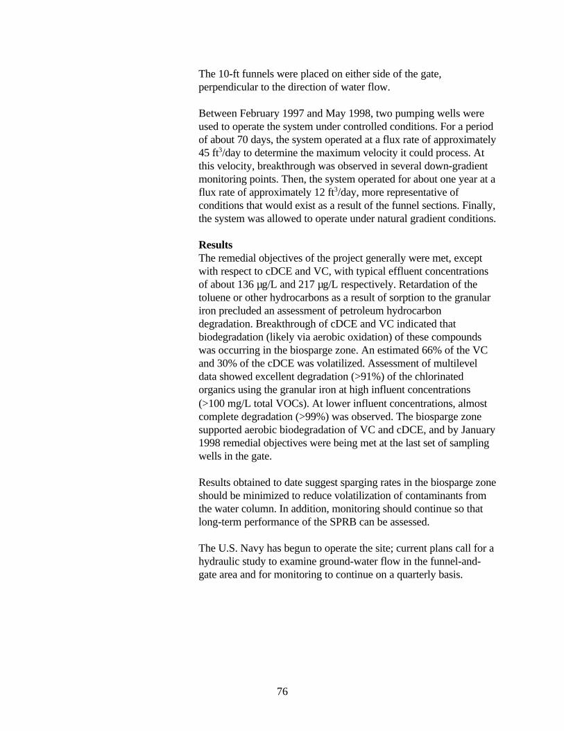
76
The 10-ft funnels were placed on either side of the gate,perpendicular to the direction of water flow.
Between February 1997 and May 1998, two pumping wells wereused to operate the system under controlled conditions. For a periodof about 70 days, the system operated at a flux rate of approximately45 ft3/day to determine the maximum velocity it could process. Atthis velocity, breakthrough was observed in several down-gradientmonitoring points. Then, the system operated for about one year at aflux rate of approximately 12 ft3/day, more representative ofconditions that would exist as a result of the funnel sections. Finally,the system was allowed to operate under natural gradient conditions.
ResultsThe remedial objectives of the project generally were met, exceptwith respect to cDCE and VC, with typical effluent concentrationsof about 136 µg/L and 217 µg/L respectively. Retardation of thetoluene or other hydrocarbons as a result of sorption to the granulariron precluded an assessment of petroleum hydrocarbondegradation. Breakthrough of cDCE and VC indicated thatbiodegradation (likely via aerobic oxidation) of these compoundswas occurring in the biosparge zone. An estimated 66% of the VCand 30% of the cDCE was volatilized. Assessment of multileveldata showed excellent degradation (>91%) of the chlorinatedorganics using the granular iron at high influent concentrations(>100 mg/L total VOCs). At lower influent concentrations, almostcomplete degradation (>99%) was observed. The biosparge zonesupported aerobic biodegradation of VC and cDCE, and by January1998 remedial objectives were being met at the last set of samplingwells in the gate.
Results obtained to date suggest sparging rates in the biosparge zoneshould be minimized to reduce volatilization of contaminants fromthe water column. In addition, monitoring should continue so thatlong-term performance of the SPRB can be assessed.
The U.S. Navy has begun to operate the site; current plans call for ahydraulic study to examine ground-water flow in the funnel-and-gate area and for monitoring to continue on a quarterly basis.

77
Nutrients

78
79
Y-12 Site, Oak Ridge National Laboratory, TN
Installation Date:December 1997November 1997
Contaminants: U, Tc, HNO3
Reactive Media: Fe0
Installation Cost: $1,000,000
Construction: Funnel and Gate Continuous Trench
Point of Contact:Baohua GuOak Ridge National LaboratoryEnvironmental Sciences Division Oak Ridge, TN 37831-6036 Tel: 423-574-7286 Fax: 423-576-8543 E-mail: [email protected]
Permeable reactive barrier (PRB) systems have been constructed intwo different ground-water pathways through the Y-12 site at theU.S. Department of Energy’s (DOE) Oak Ridge NationalLaboratory, TN.
Site BackgroundLiquid wastes, including nitric acid (HNO3) with uranium (U), andtechnetium (Tc), were placed in disposal ponds on the site from1952 to 1981. The site was capped in 1983. Leached wastes havecontaminated both ground and surface water.
The site is underlain by unconsolidated clay and regolith overlyingfractured shales. The permeability of the clay is very low(approximately 4 x 10⁻⁷ in/sec), but the weathered bedrock abovethe shales generally has a higher permeability (locally as high as 4 x10⁻⁴ in/sec). The depth to ground water is 10-15 ft, and the shallowunconsolidated unit aquifer is 10-20 ft thick. The PRBs are focusedon capturing ground water in this shallow unconsolidated zone.
Technology ApplicationPathway 1 PRBA funnel-and-gate system was installed in the area designatedPathway 1 in December 1997. The system is approximately 220 ftlong and consists of two wing walls designed to funnel groundwater to a concrete vault containing treatment canisters forevaluating different treatment media. The treatment vault consists offive vertically stacked reactors. An advantage of vertical reactors isthe ease of cleaning and replacing used or clogged iron. The wingwalls were installed to a depth of approximately 25 ft. The naturalground-water gradient and permeability contrast between the gravelbackfill in the trench and surrounding native silt and clay is designedto generate flow through the treatment zone. Barriers were installedusing a guar gum slurry for support to reduce slumping in thetrench. An enzyme breaker was used to digest the guar which wasrecycled down the trench as construction progressed.
Pathway 2 PRBA continuous trench system was installed in the area designatedPathway 2 in November 1997. It is 225 ft long, 2 ft wide, 22-30 ftdeep, and filled with gravel except for a 26-ft section in the middlethat is filled with 80 tons of zero-valent iron (Fe0). Guar gum wasadded during excavation to keep the trench walls from collapsing.
80
The trench was installed parallel to the direction of ground-waterflow.
Although total iron and ferrous iron concentrations were initiallyhigh after installation, concentrations have decreased as the pHwithin the iron has increased over time (to as high as 9 or 10). Thisinitial spike is likely a result of enhanced microbial activity from theguar used in the barrier installation. Due to the effect of the guar onground-water chemistry, nitrate concentrations increased in theupgradient wells over time. Sulfate levels in the ground water havedecreased as sulfate is reduced to sulfide. Additionally, a decreasedconcentration of calcium in ground water was observed and may beattributed to the precipitation of calcium carbonate within the ironbarrier. Continued monitoring and performance evaluation is inprogress to better understand the flow paths through the PRB, thepotential for clogging due to mineral precipitation, and the long-termeffectiveness for uranium removal. The total installation cost for the two walls was approximately$1,000,000. This includes the cost of design, construction, materials,and the reactive material.
ResultsThe goals of the project were to investigate the feasibility andeffectiveness of passive in situ treatment systems to remove thecontaminants in the ground water that are migrating to Bear Creekfrom the disposal ponds. Early results indicate that Fe0 is an efficientand cost-effective method of simultaneously removing certainradionuclides, such as U and Tc, as well as HNO3. Sampling tomonitor performance is occurring on a monthly basis.
Lessons Learned Pathway 1 PRBThe use of guar increased biological activity in the system.
Pathway 2 PRBPreliminary evaluation of hydraulic and chemical data suggests that,under wet-season hydraulic conditions, contaminated ground watermay migrate across the trench instead of down the trench asdesigned. Vertical gradients at the site appear to have a significantimpact on ground-water flow and capture. The data suggest that toeffectively operate passively in all hydraulic conditions, the trenchneeds to be longer and discharge at a lower hydraulic headdowngradient. The following modifications are planned for thePathway 2 PRB in fiscal year 1999 to enhance treatment efficiency:
81
The trench will be extended an additional 100 ft to increase theground-water capture zone.
Guar will not be used to excavate the trench extension because ofpotential geochemical impacts on the iron media, native soil, andground water observed during initial trench construction.
Ground water from the trench extension will be siphonedapproximately 800 ft to a second Fe0 treatment zone deployed insubsurface concrete boxes.
The treated water will flow into an infiltration trenchdowngradient of the second treatment zone.
82
Public School, Langton, Ontario, Canada
Installation Date:August 1993
Contaminants:PO4
3-, NO3-
Reactive Media:Fe/Ca oxides, high-Ca limestone,organic carbon
Installation Cost:$5,000
Construction:Funnel and Gate
Points of Contact:Will Robertson (NO3
-)David W. Blowes (PO4
3-)University of Waterloo,Department of EarthSciences200 University AvenueWest Waterloo, OntarioN2L 3G1 Canada
Will RobertsonTel: 519-888-4567 x6800Fax: 519-746-7484E-mail: [email protected]
David BlowesTel: 519-888-4567 x4878Fax: 519-746-7484E-mail: [email protected]
A pilot-scale demonstration of a funnel-and-gate system designed toremediate phosphate (PO4
3-) and nitrate (NO3-) was installed on the
grounds of a public school in Langton, Ontario, Canada in August1993.
Site BackgroundThe system was emplaced to remove PO4
3- and NO3- from a
large-capacity conventional septic system located on the schoolproperty that had operated over a 45-year period. The site isunderlain by a thick body of medium sand with a hydraulicconductivity of 72 ft/day. The water table is located at a depth of 10ft and the ground-water velocity is 330 ft/yr. The contaminatedaquifer is unconfined.
Technology ApplicationGround water was funneled between two walls constructed fromsealable joint sheet pilings that extend 16 ft from the central gatearea. The funnel walls extended 5 ft below the water table. Thecentral gate was 6 ft wide, 6 ft long, and extended 6 ft below thewater table. The gate contained two distinct treatment zones. ThePO4
3- treatment zone, which was 2 ft thick, contained a reactivemixture of 6% iron and calcium oxides (Fe/Ca oxides), 9% high-Calimestone, and 85% local aquifer sand. The phosphate was removedby adsorption onto Fe oxides and precipitation of Ca-PO4 phases.The 2-ft-thick NO3
- treatment zone contained wood chips thatremoved nitrate by bacterial denitrification.
CostThe installation cost was $5,000.
ResultsMonitoring over one year for NO3 and two years for PO4 indicatedsignificant drops in concentrations of both. PO4
3- concentrationsdecreased from 1.0-1.3 mg/L on the influent side of the barrier to0.3 mg/L on the effluent side. NO3
- concentrations decreased from23-82 mg/L upgradient of the gate to <2 mg/L within the gate.There are no plans to continue monitoring.
Lessons Learned

83
One lesson learned from this demonstration is that if walls are notkeyed into a underlying impermeable material, underflow must becarefully considered.
84
Savannah River Site TNX Area, Aiken, SC
Installation Date: July 1997
Contaminants: TCE, cDCE, CT, NO3
Reactive Media: Fe0
Installation Cost: $120,000
Construction: GeoSiphon Cell
Point of Contact Mark Phifer Westinghouse SRC/SRS Building 773-42A Aiken, SC 29808 Tel: 803-725-5222 Fax: 803-725-7673 E-mail: [email protected]
The GeoSiphon Cell (patent pending) was installed in the TNXflood plain at the Savannah River Site (SRS) by auger and caissonmethods in July 1997. The cell was installed to demonstratetreatment of ground water contaminated with chlorinated volatileorganic compounds (CVOCs).
Site BackgroundGround-water contamination has been detected in the TNX watertable aquifer, but not in the semi-confined or deep aquifersunderlying the site. Predominant contaminants, and averageconcentrations of each, detected in the TNX flood plain aretrichloroethylene (TCE) at 200-250 µg/L, cis-1,2-dichloroethylene(cDCE) at 20-50 µg/L, carbon tetrachloride (CT) at 15-45 µg/L, andnitrate (NO3) at 10-70 mg/L.
The TNX Area is a semi-works facility for the Savannah RiverTechnology Center, which is located 0.25 mile from the SavannahRiver near Aiken, SC. The facility was used for pilot-scale testingand evaluation of various chemical processes associated with SRS.The water table elevation averages 100 ft above mean sea levelunder the TNX site, while the Savannah River elevation averages85 ft. In the flood plain where contamination was detected, thewater table aquifer is approximately 35-40 ft thick. It consists ofinterbedded sand, silty sand, and relatively thin clay layers. Basedon testing and modeling analysis, the aquifer may be characterizedas having a horizontal hydraulic conductivity of 65 ft/day, verticalhydraulic conductivity of 30 ft/day, effective porosity of 0.15, porevelocity of 3 ft/day, and a horizontal gradient of 0.007.
Technology ApplicationThe TNX GeoSiphon Cell is a large-diameter (8-ft) well containing granular zero-valent iron (Fe0) as a treatment media (in place ofgravel pack). The cell passively induces flow by use of a siphonfrom the cell to the Savannah River. The flow is induced by thenatural hydraulic head difference between the cell and the river. Thepassively-induced flow draws contaminated ground water throughthe treatment cell, where the Fe0 reduces the CVOCs to ethane,ethene, methane, and chloride ions. Treated water is discharged tothe Savannah River.
During Phase I testing of this technology, which was completed inDecember 1997, flow through the TNX GeoSiphon Cell wasinduced by pumping and the treated water was discharged to the

85
existing TNX National Pollutant Discharge Elimination Systemoutfall. Testing indicated that TCE degradation is the limitingcompound to treatment below the Primary Drinking Water StandardMaximum Contaminant Levels within the TNX GeoSiphon Cell.Data indicated that approximately 8 gal/hr of ground watercontaminated with 200-250 µg/L of TCE could be treated, whilemaintaining the average discharge TCE concentration below 5 µg/L.Field first-order rate constants produced from the steady state TCEdata increased with flow rate from 0.347 to 0.917/hr.
During Phase II, flow through the TNX GeoSiphon Cell wasinduced by siphon and the treated water was discharged to anexisting outfall ditch that flows into the Savannah River. To allowcontinuous operation, the siphon line configuration was optimized toinclude an upward rise from the cell to the outfall ditch, an airchamber at the crest adjacent to the outfall ditch, and a steep dropinto the outfall ditch with line termination in a sump. The headdifferential available to drive the system (approximately 1.4 ft)produced a continuous flow rate of 2.5-2.7 gal/min. Approximately1.2 ft of head was utilized to drive flow through the cell itself, and approximately 0.2 ft of head was utilized to driveflow through the siphon line. Based on these results, a new siphonline will be installed between the cell and a target location, thusproducing a 5-ft head differential capable of inducing an estimated9.5 gal/min through the GeoSiphon Cell.
Phase III of this demonstration project will involve installation andoperation of a full-scale GeoSiphon Cell system for treatment of theentire TNX contaminated ground-water plume.
CostPhase I system costs are estimated at $119,155, including $26,400for iron; $27,411 for other construction materials; and $65,344 formobilization, labor, rentals, and related installation expenses.Approximately 49.7 tons of 0.25-2.0 mm (particle size) granular castiron was used in the installation of the first TNX GeoSiphon Cell(TGSC-1).
Lessons Learned The GeoSiphon Cell was selected for use at the TNX Area becauseit offers passive (no power requirements), in situ treatment at loweroperating and maintenance costs than pump-and-treat technology. Incontrast to funnel-and-gate or continuous permeable walltechnologies, the GeoSiphon Cell could be constructed using anexisting foundation and well drilling techniques. In addition, there ispotential for accelerating cleanup through the use of induced flow
86
rates greater than natural flow. With a maximum siphon lift of 25 ft,application of the GeoSiphon Cell technology was found to belimited to areas of shallow ground water such as that existing at theTNX Area.

87
Radionuclides

88
89
Fry Canyon Site, UT
Installation Date: August 1997
Contaminants: U
Reactive Media: Fe0, AFO, PO4
Design Cost: $30,000
Installation Cost: $140,000
Construction: Funnel and Gate
Points of Contact:Ed Feltcorn U.S. EPA/ORIA 401 M St., SW Washington, DC 20460 Tel: 202-564-9422 Fax: 202-565-2037 E-mail:[email protected]
David Naftz, Ph.D. U.S. Geological Survey 1745 W. 1700 South Salt Lake City, UT84104 Tel: 801-975-3389 Fax: 801-975-3424 E-mail:[email protected]
A field-scale demonstration of a permeable reactive barrier (PRB)system is underway at an abandoned uranium upgrader site in FryCanyon, UT. The U.S. Environmental Protection Agency (EPA) isthe lead agency on the site.
Site BackgroundThe ultimate goal of the demonstration is to determine thetechnological and economic feasibility of using permeable chemicalor biological obstacles, placed in the flow path, for removingdissolved metals and radionuclides from contaminated groundwater. This project is testing the performance of three permeablereactive barriers at the Fry Canyon site. Anticipated results of theresearch for each of the PRBs tested will include long-term removalefficiencies for uranium and an evaluation of the commercializationpotential for each. Specific objectives of the field demonstrationproject include: (1) hydrologic and geochemical characterization ofthe site prior to emplacement of barriers; (2) design, installation, andoperation of three PRBs; and (3) evaluation of barrier performanceand commercialization potential.
At the Fry Canyon site, the water table is approximately 8-9 ftbelow ground surface, and the underlying aquifer ranges from 1-6 ftdeep. Estimated hydrologic properties and measured hydraulicgradients indicate that ground water in the alluvial aquifer moves ata rate of about 1.5 ft/day nearly parallel to the direction of streamflow. The uranium (U) concentration in the shallow colluvial aquiferranges from 60 µg/L in water from a background well to 20,700µg/L in water beneath the tailings. The hydraulic conductivity of thebarriers is approximately 1,500 ft/day, while that of the surroundingnative material is 1 to 2 orders of magnitude smaller. Native materialconsists of poorly sorted fine- and medium-grained sand.
Technology ApplicationThe funnel-and-gate system, installed in August 1997, is comprisedof three barriers, each constructed of different reactive materials.One is bone char phosphate (PO4), another is foamed zero-valentiron (Fe0) pellets, and the third is amorphous ferric oxide (AFO).Each barrier is approximately 7 ft wide, 3 ft thick, and 4 ft deep.Approximately 110 ft3 of material was used in each barrier. Eachcontains 22 monitoring points, a water-quality mini-monitor, fourpressure transducers, and a flow-sensor port. According tosteady-state modeling results, ground-water velocities in the reactivewalls are about 4.5 ft/day.
90
CostThe EPA and U.S. Geological Survey have estimated that thedesign cost (engineering design and planning for the funnel-and-gate construction) for this system totals $30,000. The installationcost, including construction, materials, and the reactive materials,totals $140,000. These estimates do not include bench-scale testingof the candidate barrier materials.
ResultsOverall, results to date show that the system is controlling uraniummigration in Fry Canyon. One year of uranium-concentration datahave been collected from the three PRBs installed using funnel-and-gate designs. The input uranium concentrations are significantlydifferent for each PRB, ranging from less than 1,000 mg/L in thePO4 PRB to higher than 20,000 mg/L in the AFO ZVI. The inputuranium concentrations to each of the PRBs also vary seasonally byapproximately 4,000 to 7,000 mg/L. During the first year ofoperation, the PRBs are removing the majority of incominguranium; however, the percentage of uranium removal varies withtime and barrier material. The ZVI PRB has consistently removedgreater than 99.9 percent of the input uranium concentration inflow-path 1. The percentage of uranium removed in the PO4 andAFO PRBs is slightly less than the ZVI PRB. Except for twomonitoring periods, over 90 percent of the input uraniumconcentration was removed in the PO4 barrier. The AFO PRBremoved over 90 percent of the input uranium concentration throughNovember 1997. From January 1998 through September 1998 theuranium removal percentage was reduced to less than 90 percent.Studies will continue to evaluate the barriers under varyinghydrologic and geochemical conditions. Final results will bepresented after peer review in the report to be issued by end of fiscalyear 1999.
Lessons Learned The Fry Canyon project has shown continued promise for use ofPRB technology at appropriate sites (as determined bycharacterization). Uranium reduction ratios were calculated for allwater samples collected from each reactive wall from September1997 through January 1998. These calculations indicate that the Fe0
reactive chemical wall has been most efficient in removing uraniumfrom ground water; however, uranium removal efficiencies in thePO4 and AFO walls also have been high. Other lessons learned todate include the following:
Project results thus far indicate that the PO4 binder system can beused to customize reactive materials effectively.
91
Data also suggest, however, that the dissolution of Fe0 and itsassociated clogging could present problems, while the AFO is lesssubject to clogging and iron release. Although the possibilityexists for elevated iron concentrations downgradient of the PRB(which could cause degradation in water quality not present beforebarrier installation); to date, iron concentrations in downgradientwells do not seem to present a large water-quality problem.
Numerous geochemical, hydrological, and other factors that affecturanium removal efficiencies and processes in each of the PRBs arecurrently being evaluated. These factors include:
Changes in the amount and velocity of water flowing through thePRBs
Type and quantities of minerals forming within the PRBs Leakage between underlying “no-flow” paths through the PRBs
The following potential problems also are being assessed: In a low-gradient system like Fry Canyon, it is difficult to
estimate mass of treated water and, at times, whether there iseven flow through some of the gate structures. This presents anunknown to regulators in estimating total mass of contaminantthat will be cleaned up per unit of time since PRB deployment.
Seasonal changes are apparent in the PRBs’ efficiency in removing uranium. The processes causing these changes need tobe identified in order to effectively determine long-term clean-upgoals.
PRBs that are placed adjacent to ephemeral channels could bedestroyed or have their long-term function significantly compromised during intense thunderstorm events in the Fry Creek drainage basin without proper erosion control measures.
Ground settling could compromise the lack of visual impact thatPRBs have in future remediation applications and could impactmonitoring wells.

92
Y-12 Site, Oak Ridge National Laboratory, TN
Installation Date:December 1997November 1997
Contaminants: U, Tc, HNO3
Reactive Media: Fe0
Installation Cost: $1,000,000
Construction: Funnel and Gate Continuous Trench
Point of Contact:Baohua GuOak Ridge National LaboratoryEnvironmental Sciences Division Oak Ridge, TN 37831-6036 Tel: 423-574-7286 Fax: 423-576-8543 E-mail: [email protected]
Permeable reactive barrier (PRB) systems have been constructed intwo different ground-water pathways through the Y-12 site at theU.S. Department of Energy’s (DOE) Oak Ridge NationalLaboratory, TN.
Site BackgroundLiquid wastes, including nitric acid (HNO3) with uranium (U), andtechnetium (Tc), were placed in disposal ponds on the site from1952 to 1981. The site was capped in 1983. Leached wastes havecontaminated both ground and surface water.
The site is underlain by unconsolidated clay and regolith overlyingfractured shales. The permeability of the clay is very low(approximately 4 x 10⁻⁷ in/sec), but the weathered bedrock abovethe shales generally has a higher permeability (locally as high as 4 x10⁻⁴ in/sec). The depth to ground water is 10-15 ft, and the shallowunconsolidated unit aquifer is 10-20 ft thick. The PRBs are focusedon capturing ground water in this shallow unconsolidated zone.
Technology ApplicationPathway 1 PRBA funnel-and-gate system was installed in the area designatedPathway 1 in December 1997. The system is approximately 220 ftlong and consists of two wing walls designed to funnel groundwater to a concrete vault containing treatment canisters forevaluating different treatment media. The treatment vault consists offive vertically stacked reactors. An advantage of vertical reactors isthe ease of cleaning and replacing used or clogged iron. The wingwalls were installed to a depth of approximately 25 ft. The naturalground-water gradient and permeability contrast between the gravelbackfill in the trench and surrounding native silt and clay is designedto generate flow through the treatment zone. Barriers were installedusing a guar gum slurry for support to reduce slumping in thetrench. An enzyme breaker was used to digest the guar which wasrecycled down the trench as construction progressed.
Pathway 2 PRBA continuous trench system was installed in the area designatedPathway 2 in November 1997. It is 225 ft long, 2 ft wide, 22-30 ftdeep, and filled with gravel except for a 26-ft section in the middlethat is filled with 80 tons of zero-valent iron (Fe0). Guar gum wasadded during excavation to keep the trench walls from collapsing.

93
The trench was installed parallel to the direction of ground-waterflow.
Although total iron and ferrous iron concentrations were initiallyhigh after installation, concentrations have decreased as the pHwithin the iron has increased over time (to as high as 9 or 10). Thisinitial spike is likely a result of enhanced microbial activity from theguar used in the barrier installation. Due to the effect of the guar onground-water chemistry, nitrate concentrations increased in theupgradient wells over time. Sulfate levels in the ground water havedecreased as sulfate is reduced to sulfide. Additionally, a decreasedconcentration of calcium in ground water was observed and may beattributed to the precipitation of calcium carbonate within the ironbarrier. Continued monitoring and performance evaluation is inprogress to better understand the flow paths through the PRB, thepotential for clogging due to mineral precipitation, and the long-termeffectiveness for uranium removal. The total installation cost for the two walls was approximately$1,000,000. This includes the cost of design, construction, materials,and the reactive material.
ResultsThe goals of the project were to investigate the feasibility andeffectiveness of passive in situ treatment systems to remove thecontaminants in the ground water that are migrating to Bear Creekfrom the disposal ponds. Early results indicate that Fe0 is an efficientand cost-effective method of simultaneously removing certainradionuclides, such as U and Tc, as well as HNO3. Sampling tomonitor performance is occurring on a monthly basis.
Lessons Learned Pathway 1 PRBThe use of guar increased biological activity in the system.
Pathway 2 PRBPreliminary evaluation of hydraulic and chemical data suggests that,under wet-season hydraulic conditions, contaminated ground watermay migrate across the trench instead of down the trench asdesigned. Vertical gradients at the site appear to have a significantimpact on ground-water flow and capture. The data suggest that toeffectively operate passively in all hydraulic conditions, the trenchneeds to be longer and discharge at a lower hydraulic headdowngradient. The following modifications are planned for thePathway 2 PRB in fiscal year 1999 to enhance treatment efficiency:

94
The trench will be extended an additional 100 ft to increase theground-water capture zone.
Guar will not be used to excavate the trench extension because ofpotential geochemical impacts on the iron media, native soil, andground water observed during initial trench construction.
Ground water from the trench extension will be siphonedapproximately 800 ft to a second Fe0 treatment zone deployed insubsurface concrete boxes.
The treated water will flow into an infiltration trenchdowngradient of the second treatment zone.

95
Other Organic Contaminants

96
97
Marzone Inc./Chevron Chemical Company, Tifton, GA
Installation Date:August 1998
Contaminants:BHC, beta-BHC, DDD,DDT, xylene,ethylbenzene, lindane,and methyl parathion
Reactive Media:Activated carbon
Design Cost:$230,000
Installation Cost:$520,000
Construction:Funnel and Gate
Point of Contact:Annie GodfreyU.S. EnvironmentalProtection Agency,Region 461 Forsyth StreetAtlanta, GA 30303Tel: 404-562-8919Fax: 404-562-8896E-mail:[email protected]
A permeable reactive barrier (PRB) was installed in August 1998 atOperable Unit 1 of the Marzone site in Tifton, GA, to remediateground water contaminated with pesticides and volatile organiccompounds (VOCs).
Site BackgroundA 1994 Record of Decision originally selected a pump-and-treatsystem to remediate the ground water. During remedial designactivities, however, it was determined that an in situ treatmentsystem such as a funnel-and-gate system may be a more appropriatetechnology for the specific site conditions. The Marzone facility wasused as a pesticide formulation facility from 1950 until the 1980s.Ground-water contaminants of concern and their initial maximumconcentrations are: alpha-hexachlorobenzene (BHC) (60 mg/L),beta-BHC (98.5 mg/L), DDD (7.6 mg/L), DDT (9.3 mg/L), xylene(94,000 mg/L), ethylbenzene (6,100 mg/L), lindane (54.6 mg/L)and methyl parathion (47 mg/L). A shallow aquifer is located at adepth of 7 ft and a deeper aquifer exists at approximately 25 ft.Hydraulic conductivity is estimated at 2.9-4.6 ft/day. Soils in thisarea consist of a mixture of sand, sandy clay, and clay.
Technology ApplicationThe modified funnel-and-gate system comprises a 400-ft barrier wallthat was installed using a vibrating beam technology. A collectiontrench lined with geotextile and filled with granular drain materialwas constructed upgradient of and parallel to the barrier wall.Ground water collected in this trench moves by way of a slottedwell screen and associated piping into treatment vaults containingapproximately 1,800 pounds of activated carbon located betweenthe collection trench and barrier wall. From the treatment vaults,ground water moves slowly (1-2 gal/min) by way of piping throughthe barrier wall and into a distribution trench of similar constructionas the collection trench but running perpendicular to the barrier wall.
CostDesign costs for the Marzone PRB system were $230,000.Installation costs, including construction, materials, and reactivematerial, are estimated at $520,000.
ResultsCleanup goals for the contaminants of concern are: 0.00003 mg/Lfor alpha-BHC, 0.0001 mg/L for beta-BHC, 0.00077 mg/L for
98
DDD, 0.00054 mg/L for DDT, 10 mg/L for xylene, 0.7 mg/L forethylbenzene, 0.0002 mg/L for lindane, and 0.0039 mg/L for methylparathion. Sampling of the treatment vault effluent is conducted on amonthly basis. Preliminary sampling indicates contaminantconcentrations that are below detection levels.
Lessons LearnedThe funnel-and-gate system was selected for use because if offeredless impact to the surrounding community than other treatmenttechnologies, while being partially self-operational. Flushing of thesystem is required every 3-4 weeks in order to reinitiate flow; as aresult, costs for operation and maintenance are higher thatanticipated.

99
Bibliography

100
101
Bibliography of Field Applications of Permeable Reactive Barrier Technology
Appleton, E.L. 1996. “A Nickel-Iron Wall Against Contaminated Groundwater.” EnvironmentalScience & Technology, 30:12, 536A-539A.
Bain, J.G.; D.W. Blowes; S.G. Benner. 1998. “Treatment of Acidic, Mine-Associated Dischargeto a Lake Using a Permeable Reactive Barrier.” 1998 American Geophysical Union SpringMeeting, 26-29 May, Boston, MA.
Baker, M.J.; D.W. Blowes; C.J. Ptacek. 1997. “Phosphorous Adsorption and Precipitation in aPermeable Reactive Wall: Applications for Wastewater Disposal Systems.” 1997 InternationalContainment Technology Conference and Exhibition, 9-12 February, St. Petersburg, FL. 697-703. CONF-970208-Proc. DE98001967.
Barton, W.D.; P.M. Craig; W.C. Stone. 1997. “Two Passive Groundwater Treatment Installationsat DOE Facilities.” 1997 International Containment Technology Conference and Exhibition, 9-12February, St. Petersburg, FL. 827-834. CONF-970208-Proc. DE98001967.
Benner, S.G.; D.W. Blowes; C.J. Ptacek. 1997. “A Full-Scale Porous Reactive Wall forPrevention of Acid Mine Drainage.” Ground Water Monitoring and Remediation. 17:4 (Fall):99-107.
Benner, S.G.; D.W. Blowes; C.J. Ptacek. 1997. “Porous Reactive Wall for Prevention of AcidMine Drainage: Results of a Full-Scale Field Demonstration.” 1997 International ContainmentTechnology Conference and Exhibition, 9-12 February, St. Petersburg, FL. 835-843. CONF-970208-Proc. DE98001967.
Benner, S.G.; D.W. Blowes; C.J. Ptacek. 1997. “Sulfate Reduction in a Permeable Reactive Wallfor Prevention of Acid Mine Drainage.” The 213th National Meeting of the American ChemicalSociety, San Francisco, CA. Preprint Extended Abstracts, Division of Environmental Chemistry.37:1, 140-141.
Bennett, T.A.; D.W. Blowes; R.W. Puls; R.W. Gillham; C.J. Hanton-Fong; C.J. Ptacek; S.F.O’Hannesin; J.L. Vogan. 1997. “Design and Installation of an In Situ Porous Reactive Wall forTreatment of Cr(VI) and Trichloroethylene in Groundwater.” The 213th National Meeting of theAmerican Chemical Society, San Francisco, CA. Preprint Extended Abstracts, Division ofEnvironmental Chemistry. 37:1, 243-245.
Bennett, T.A.; D.W. Blowes; R.W. Puls; R.W. Gillham; C.J. Hanton-Fong; C.J. Ptacek; S.F.O’Hannesin; J.L. Vogan. 1998. “An In-Situ Permeable Iron-Filings Wall to Remediate Cr(VI) andTCE Contaminated Groundwater.” Subsurface Barrier Technologies Conference: EngineeringAdvancements and Application Considerations for Innovative Barrier Technologies, 26-27January 1998, Tucson, AZ. International Business Communications, Southborough, MA.
102
Betts, K.S. 1998. “Novel Barrier Remediates Chlorinated Solvents.” Environmental Science &Technology, 1 November 1998, 495A.
Blowes, D.W.; C.J. Ptacek; K.R. Waybrant; J.D. Bain; W.D. Robertson. 1994. “In Situ Treatmentof Mine Drainage Water Using Porous Reactive Walls.” The “New Economy”: Green Needs andOpportunities. Environment and Energy Conference of Ontario, November 15 & 16, 1994,Toronto, Ontario.
Blowes, D.W.; C.J. Ptacek; J.A. Cherry; R.W. Gillham; W.D. Robertson. 1995. “PassiveRemediation of Groundwater Using In Situ Treatment Curtains.” Geoenvironment 2000:Characterization, Containment, Remediation, and Performance in Environmental Geotechnics.American Society of Civil Engineers, Reston, VA. Geotechnical special publication 46 (v.2),1588-1607.
Blowes, D.W.; C.J. Ptacek; C.J. Hanton-Fong; J.L. Jambor. 1995. “In Situ Remediation ofChromium Contaminated Groundwater Using Zero-Valent Iron.” The 209th American ChemicalSociety National Meeting, Division of Environmental Chemistry, 2-7 April 1995, Anaheim, CA.Preprint Extended Abstracts. 35:1, 780-783.
Blowes, D.W.; C.J. Ptacek; K.R. Waybrant; J.G. Bain. 1995. “In Situ Treatment of MineDrainage Water Using Porous Reactive Walls.” Proceedings, Biominet Annual General Meetingon Biotechnology and the Mining Environment, 26 January 1995, Ottawa, Ontario. 119-128.
Blowes, D.W.; C.J. Ptacek; J.G. Bain; K.R. Waybrant; W.D. Robertson. 1995. “Treatment ofMine Drainage Water Using In Situ Permeable Reactive Walls.” Proceedings, Sudbury '95Symposium on Mining and the Environment, 28 May-1 June 1995, Sudbury, Ontario. V.3,979-987.
Blowes, D.W.; R.W. Puls; T.A. Bennett; R.W. Gillam; C.J. Hanton-Fong; C.J. Ptacek. 1997.“In-Situ Porous Reactive Wall for Treatment of Cr(VI) and Trichloroethylene in Groundwater.” 1997 International Containment Technology Conference, 9-12 February 1997, St. Petersburg,FL. 851-857. CONF-970208-Proc. DE98001967.
Blowes, D.W.; R.W. Puls; C. Ptacek; T.A. Bennett; K.U. Mayer; A.R. Pratt. 1998. “PermeableReactive Barrier for Cr(VI) Treatment: from Concept to Implementation.” 1998 AmericanGeophysical Union Fall Meeting, 6-10 December, San Francisco, CA.
Borden, R.C. ; R.T. Goin; C.M. Kao; C.G. Rosal. 1996. Enhanced Bioremediation of BTEX Using Immobilized Nutrients: Field Demonstration and Monitoring. 68 pp. EPA/600/R-96/145.PB97-186290.
Borden, Robert C.; Russell Todd Goin; Chih-Ming Kao. 1997. “Control of BTEX MigrationUsing a Biologically Enhanced Permeable Barrier.” Ground Water Monitoring & Remediation.17:1, 70-80.
103
Bowles, M.; L.R. Bentley; J. Barker; D. Thomas; D. Granger; H. Jacobs; S. Rimbey; B. Hoyne.1997. “The East Garrington Trench and Gate System: It Works,” The 6th Annual Conference onGroundwater and Soil Remediation, Montreal, 18-21 June 1997.
Bowman, Robert. 1999. “Pilot-Scale Testing of a Surfactant-Modified Zeolite PRB.” GroundWater Currents. EPA/542/N-99/002. (Available through http://clu-in.org.)
Byerly, B.T.; W.D. Robertson. 1996. “Remediation of Landfill Leachate Using Infiltration andReactive Barrier Technology: a Field Study.” Environmental Biotechnology: Principles andApplications. Kluwer Academic Pub. ISBN: 0792338774. 417-430.
Caruana, Alex. 1998. “1,200-Foot Permeable Reactive Barrier in Use at the Denver FederalCenter.” Ground Water Currents. March, No. 27. (Available through http://clu-in.org.)
Chapman, S.W.; B.T. Byerly; D.J. Smyth; R.D. Wilson; D.M. Mackay. 1997. “Semi-PassiveOxygen Release Barrier for Enhancement of Intrinsic Bioremediation.” In Situ and On-SiteBioremediation: Volume 4. Battelle Press, Columbus, OH. 209-214.
Clark, D.K.; T.L. Hineline. 1996. “Evaluation of Funnel and Gate System for In Situ Treatment ofTCE Plume.” Proceedings of the 28th Mid-Atlantic Industrial and Hazardous Waste Conference,14-17 July 1996, Buffalo, NY. Technomic Publishing Co., Lancaster, PA. 337-341.
Clark, D.K.; T.L. Hineline; J. Vogan; S.F. O’Hannesin. 1996. “In Situ Treatment of a TCE PlumeUsing a Funnel and Gate System: a Case Study.” Petroleum Hydrocarbons and OrganicChemicals in Groundwater: Prevention, Detection, and Restoration. National NWWA/APIConference, November 1996, Houston, TX. National Water Well Association. 165-174.
Clark, D.K.; J. Vogan; S. O’Hannesin. 1996. “Application of Passive Remediation forGroundwater Impacted with Chlorinated Solvents.” Remediation Management, 4th quarter 1996.
Cole, Jason D.; Sandra Woods; Kenneth Williamson; David Roberts. 1998. “Demonstration of aPermeable Barrier Technology for Pentachlorophenol-Contaminated Groundwater.” Designingand Applying Treatment Technologies: Remediation of Chlorinated and Recalcitrant Compounds.Battelle Press, Columbus, OH. 121-126.
Cumming, Lydia; Bruce Sass; Arun Gavaskar; Eric Drescher; Travis Williamson; MelodyDrescher. 1998. “Bench-Scale Tracer Tests for Evaluating Hydraulic Performance of PermeableBarrier Media.” Designing and Applying Treatment Technologies: Remediation of Chlorinatedand Recalcitrant Compounds. Battelle Press, Columbus, OH. 97-102.
Curtis, G.P.; P.B. McMahon. 1998. “Numerical Simulation of Geochemical Reactions at a ZeroValent Iron Wall Remediation Site.” 1998 American Geophysical Union Spring Meeting, 26-29May, Boston, MA.
104
Dwyer, B.P.; D.C. Marozas; K. Cantrell; W. Stewart. 1996. Laboratory and Field ScaleDemonstration of Reactive Barrier Systems. 13 pp. SAND–96-2500. DE97001355.
Dwyer, B.P.; D.C. Marozas. 1997. “In-Situ Remediation of Uranium ContaminatedGroundwater.” 1997 International Containment Technology Conference and Exhibition, 9-12February, St. Petersburg, FL. 844-850. CONF-970208-Proc. DE98001967.
Fairweather, V. 1996. “When Toxics Meet Metal.” Civil Engineering—ASCE, 66:5, 44-48.
Federal Remediation Technologies Roundtable. 1998. Remediation Case Studies: InnovativeGroundwater Treatment Technologies, Volume 11. EPA/542/R-98/015. PB99-106775.
Feltcorn, Ed; Randy Breeden. 1997. “Reactive Barriers for Uranium Removal.” Ground WaterCurrents. December, No. 26. (Available through http://clu-in.org.)
Focht, R.M.; R.W. Gillham. 1995. “Dechlorination of 1,2,3-Trichloropropane by Zero-ValentIron.” The 209th American Chemical Society National Meeting, Division of EnvironmentalChemistry, 2-7 April 1995, Anaheim, CA. Preprint Extended Abstracts. 35:1, 741-743.
Focht, R.; J. Vogan; S. O’Hannesin. 1996. “Field Application of Reactive Iron Walls for In-SituDegradation of Volatile Organic Compounds in Groundwater.” Remediation, 6:3, 81-94.
Focht, R.M.; J.L. Vogan; S.F. O’Hannesin. 1997. “Hydraulic Studies of In-Situ PermeableReactive Barriers.” 1997 International Containment Technology Conference and Exhibition, 9-12February, St. Petersburg, FL. 975-981. CONF-970208-Proc. DE98001967.
Fruchter, J.S.; C.R. Cole; M.D. Williams; V.R. Vermeul; S.S. Teel; J.E. Amonette; J.E. Szecsody;S.B. Yabusaki. 1997. “Creation of a Subsurface Permeable Treatment Barrier Using In-SituRedox Manipulation.” 1997 International Containment Technology Conference and Exhibition, 9-12 February, St. Petersburg, FL. 704-710. CONF-970208-Proc. DE98001967.
Gallant, William A.; Brian Myller. 1997. “The Results of a Zero Valence Metal Reactive WallDemonstration at Lowry AFB, Colorado.” Air & Waste Management Association’s 90thAnnual Meeting & Exhibition, 8-13 June 1997, Toronto, Ontario, Canada.
Gallinati, J.D.; S.D. Warner. 1994. “Hydraulic Design Considerations for Permeable In-SituGroundwater Treatment Walls.” Association of Groundwater Scientists and Engineers, NGWA,October 1994, Las Vegas, NV.
Gallinati, J.D.; S.D. Warner; C.L. Yamane; F.S. Szerdy; D.A. Hankins; D.W. Major. 1995.“Design and Evaluation of an In-Situ Ground Water Treatment Wall Composed of Zero-ValentIron.” Ground Water, 33:5, 834-835.
Gavaskar, Arun; Neeraj Gupta; Bruce Sass; Tad Fox; Robert Jonosy. 1997. Design Guidance forApplication of Permeable Barriers to Remediate Dissolved Chlorinated Solvents. 202 pp. NTIS.AL/EQ-TR-1997-0014. AD-A327159.
105
Gillham, R.W.; D.R. Burris. 1992. “Recent Developments in Permeable In Situ Treatment Wallsfor Remediation of Contaminated Groundwater.” Third International Conference on GroundWater Quality Research: Subsurface Restoration Conference, 21-24 June 1992, Dallas, TX. 66-68.
Gillham, R.W.; D.W. Blowes; C.J. Ptacek; S.F. O’Hannesin. 1994. “Use of Zero-Valent Metals inIn-Situ Remediation of Contaminated Ground Water.” In-Situ Remediation: Scientific Basis forCurrent and Future Technologies—33rd Hanford Symposium on Health and the Environment.Battelle Press, Columbus, OH. Part 2, 913-930.
Gillham, R.W.; S.O. O’Hannesin; S. Orth; J. Vogan. 1996. “Field Applications of MetalEnhanced Dehalogenation of Chlorinated Organic Contaminants.” WEFTEC ‘95: 68th AnnualConference & Exposition of the Water Environment Federation, 21-25 Oct 1995, Miami Beach,FL. Water Environment Federation, Alexandria, VA. p 224. CONF-951023.
Gillham, R. W.; S. F. O’Hannesin; M. S. Odziemkowski; R. A. Garcia-Delgado; R. M. Focht; W.H. Matulewicz; J. E. Rhodes. 1997. “Enhanced Degradation of VOCs: Laboratory and Pilot-ScaleField Demonstration.” 1997 International Containment Technology Conference, 9-12 February,St. Petersburg, FL. 858-863.
Gillham, R.W.; D.R. Burris. 1997. “Recent Developments in Permeable in Situ Treatment Wallsfor Remediation of Contaminated Groundwater.” Subsurface Restoration, Ann Arbor Press,Chelsea, MI. 343-356.
Gillham, R. 1998. “In Situ Remediation of Groundwater Using Granular Iron: Case Studies.”Subsurface Barrier Technologies Conference: Engineering Advancements and ApplicationConsiderations for Innovative Barrier Technologies, 26-27 January 1998, Tucson, AZ.International Business Communications, Southborough, MA.
Gravelding, D. 1998. “Design and Construction of a 1200 Foot Funnel & Gate System.”Subsurface Barrier Technologies Conference: Engineering Advancements and ApplicationConsiderations for Innovative Barrier Technologies, 26-27 January 1998, Tucson, AZ.International Business Communications, Southborough, MA.
Gupta, N.; B.M. Sass; A.R. Gavaskar; J.R. Sminchak; T.C. Fox; F.A. Snyder; D. O’Dwyer; C.Reeter. 1998. “Hydraulic Evaluation of a Permeable Barrier Using Tracer Tests, VelocityMeasurements, and Modeling.” Designing and Applying Treatment Technologies: Remediation ofChlorinated and Recalcitrant Compounds. Battelle Press, Columbus, OH. 157-162.
106
Haigh, Dale. 1997. “Reactive Barrier System Reduces TCE in Northern Ireland Installation.”Water Online, 08/05/97. (Available at http://news.wateronline.com/case-studies/CS707292.html.)
Hayes, Joseph J.; Donald L. Marcus. 1997. “Design of a Permeable Reactive Barrier In SituRemediation System, Vermont Site.” In Situ Remediation of the Geoenvironment. AmericanSociety of Civil Engineers, Reston, VA. Geotechnical Special Publication No. 71, 56-67.
Hubble, D.W.; R.W. Gillham; J.A. Cherry. 1997. “Emplacement of Zero-Valent Iron forRemediation of Deep Containment Plumes.” 1997 International Containment TechnologyConference, 9-12 February, St. Petersburg. 872-878. CONF-970208-Proc. DE98001967.
Janosy, R. J.; J. E. Hicks; D. O`Sullivan. 1998. “Site Characterization to Aid in the Design of aPermeable Barrier at Dover AFB.” Designing and Applying Treatment Technologies:Remediation of Chlorinated and Recalcitrant Compounds. Battelle Press, Columbus, OH.127-132.
Jefferis, S.A.; G.H. Norris; A.O. Thomas. 1997. “Developments in Permeable and LowPermeability Barriers.” 1997 International Containment Technology Conference and Exhibition,9-12 February, St. Petersburg, FL. 817-826. CONF-970208-Proc. DE98001967.
Jefferis, Stephan A.; Graham H. Norris. 1998. “Reactive Treatment Zones: Concepts and a CaseHistory.” NATO/CCMS Pilot Study: Evaluation of Demonstrated and Emerging Technologies forthe Treatment of Contaminated Land and Groundwater—Phase III. Session on Treatment Wallsand Permeable Reactive Barriers, No. 229. 66-76. EPA/542/R-98/003.
Korte, Nic; Olivia R. West; Liyuan Liang; Mark J. Pelfrey; Thomas C. Houk. 1997. “A Field-Scale Test Facility for Permeable Reactive Barriers at the Portsmouth Gaseous Diffusion Plant.”Federal Facilities Environmental Journal. 8:3, 105-104.
Lee, David R.; David J.A. Smyth; Steve G. Shikaze; Robin Jowett; Dale S. Hartwig; ClaireMilloy. 1998. “Wall-and-Curtain for Passive Collection/Treatment of Contaminant Plumes.”Designing and Applying Treatment Technologies: Remediation of Chlorinated and RecalcitrantCompounds. Battelle Press, Columbus, OH. 77-84.
Liang, L.; O.R. West; N.E. Korte; et al. 1997. The X-625 Groundwater Treatment Facility: AField-Scale Test of Trichloroethylene Dechlorination Using Iron Filings for the X-120/X-749Groundwater Plume. 71 pp. ORNL/TM--13410. DE98007047.
Mackenzie, P. D.; S. S. Baghel; G. R. Eykholt; D. P. Horney; J. J. Salvo; T. M. Sivavec. 1995.“Pilot-Scale Demonstration of Reductive Dechlorination of Chlorinated Ethenes by Iron Metal.”The 209th National Meeting of the American Chemical Society, Anaheim, CA. Preprint ExtendedAbstracts, Division of Environmental Chemistry. 35:1, 796-799.
107
Manz, C.; K. Quinn. 1997. “Permeable Treatment Wall Design and Cost Analysis.” 1997International Containment Technology Conference and Exhibition, 9-12 February, St. Petersburg,FL. 788-794. CONF-970208-Proc. DE98001967.
Marcus, Donald L.; James Farrell. 1998. “Reactant Sand-Fracking Pilot Test Results.” Designingand Applying Treatment Technologies: Remediation of Chlorinated and Recalcitrant Compounds.Battelle Press, Columbus, OH. 85-90.
Mayer, K.U.; D.W. Blowes; E.O. Frind. 1998. “Formulation of the Model MIN3P and ItsApplication to an In-Situ Reactive Barrier.” 1998 American Geophysical Union Spring Meeting,26-29 May, Boston, MA.
Morkin, Mary; J. Barker; R. Devlin; Michaye McMaster. 1998. “In Situ Sequential Treatment of aMixed Organic Plume Using Granular Iron, O2 and CO2 Sparging.” Designing and ApplyingTreatment Technologies: Remediation of Chlorinated and Recalcitrant Compounds. BattellePress, Columbus, OH. 289-294.
Morrison, Stan. 1998. Research and Application of Permeable Reactive Barriers. U.S.Department of Energy, Grand Junction Office. 50 pp. (Available at http://www.gwrtac.org/html/tech_status.html)
Morrison, Stan. 1998. “Fry Canyon Demonstration Project.” Subsurface Barrier TechnologiesConference: Engineering Advancements and Application Considerations for Innovative BarrierTechnologies, 26-27 January 1998, Tucson, AZ. International Business Communications,Southborough, MA.
Muza, Richard. 1997. “Reactive Walls Demonstrated.” Ground Water Currents. April, No. 24. (Available through http://clu-in.org.)
Naftz, D.L. 1997. “Field Demonstration of Reactive Chemical Barriers to Control Radionuclideand Trace-Element Contamination in Ground Water, Fry Canyon, Utah.” 1997 GSA AnnualMeeting, 20-23 October 1997, Salt Lake City, UT. A-335.
Naftz, D.L.; G.W. Freethey; J.A. Davis; R. Breeden; E. Feltcorn; R. Wilhelm; R.R. Spangler; S.J.Morrison; B. Lewis; J. Brown. 1997. “Hydrologic Characterization of the Fry Canyon, Utah SitePrior to Field Demonstration of Reactive Chemical Barriers to Control Radionuclide andTrace-Element Contamination in Groundwater.” 1997 International Containment TechnologyConference and Exhibition, 9-12 February, St. Petersburg, FL. 725-729. CONF-970208-Proc.DE98001967.
O’Brien, K.; G. Keyes; N. Sherman. 1997. “Implementation of a Funnel-and-Gate RemediationSystem.” 1997 International Containment Technology Conference and Exhibition, 9-12 February,St. Petersburg, FL. 895-901. CONF-970208-Proc. DE98001967.
108
O’Hannesin, S.F.; R.W. Gillham. 1992. “A Permeable Reaction Wall for In Situ Degradation ofHalogenated Organic Compounds.” The 45th Canadian Geotechnical Society Conference, 25-28October 1992, Toronto, Ontario.
O’Hannesin, S.F.; R.W. Gillham. 1993. “In Situ Degradation of Halogenated Organics byPermeable Reaction Wall.” Ground Water Currents, March. EPA/542/N-93/003. (Availablethrough http://clu-in.org)
O’Hannesin, S.F.; R.W. Gillham. 1998. “Long-Term Performance of an In Situ ‘Iron Wall’ forRemediation of VOCs.” Ground Water. 36:1, 164-170.
Porter, J. 1998. “Greening Process.” Ground Engineering, 31:7, 32-33.
Powell, R.M.; R.W. Puls; D.W. Blowes; R.W. Gillham; D. Schultz. 1998. Permeable ReactiveBarrier Technologies for Contaminant Remediation. 114 pp. EPA/600/R-98/125. (Also availableat http://www.epa.gov/ada/reports.html)
Puls, R. W.; D. A. Clark; C. J. Paul; J. Vardy. 1994. “Transport and Transformation ofHexavalent Chromium Through Soils and into Ground Water.” Journal of Soil Contamination,3:2, 203-224. (Also available from NTIS as EPA/600/J-94/315. Order PB94-197597.)
Puls, R. W.; R. M. Powell; C. J. Paul. 1995. “In Situ Remediation of Ground Water Contaminatedwith Chromate and Chlorinated Solvents Using Zero-Valent Iron: a Field Study.” The 209thNational Meeting of the American Chemical Society, Anaheim, CA. Preprint Extended Abstracts,Division of Environmental Chemistry. 35:1, 788-791.
Puls, R. W.; C. J. Paul; R. M. Powell. 1996. “In Situ Immobilization and Detoxification ofChromate-Contaminated Ground Water Using Zero-Valent Iron: Field Experiments at the USCGSupport Center, Elizabeth City, North Carolina.” The 4th Great Lakes Geotechnical andGeoenvironmental Conference: In-Situ Remediation of Contaminated Sites, University of Illinois,Chicago, IL. 69-77. (Paper also available from NTIS. Order PB96-169313.)
Puls, R.W.; C.J. Paul; R.M. Powell. 1996. “Remediation of Chromate-Contaminated GroundWater Using Zero-Valent Iron: Field Test at USCG Support Center, Elizabeth City, NorthCarolina.” The 9th Annual Conference on Hazardous Waste Remediation: 1996 HSRC/WERCJoint Conference on the Environment. Kansas State University, Manhattan, KS. 69-77. (Paperalso available from NTIS. Order PB97-122915.)
Puls, R.W.; D.W. Blowes; R.M. Powell; D.S. Schultz; J. Vogan. 1997. NGWA Workshop onPermeable Reactive Barriers in Ground Water. 10 pp. EPA/600/A-97/029. PB97-192827.
109
Puls, R.W.; C.J. Paul; P.J. Clark. 1997. “Remediation of Chromate-Contaminated Ground WaterUsing an In-Situ Permeable Reactive Mixture: Field Pilot Test, Elizabeth City, North Carolina.”The 213th National Meeting of the American Chemical Society, San Francisco, CA. PreprintExtended Abstracts, Division of Environmental Chemistry. 37:1. 241-243. (Paper also availablefrom NTIS as EPA/600/A-97/002. Order PB97-192819)
Puls, Robert W.; Robert W. Powell. 1997. Permeable Reactive Subsurface Barriers for theInterception and Remediation of Chlorinated Hydrocarbon and Chromium(VI) Plumes in GroundWater. 4 pp. EPA/600/F-97/008. (Available at http://www.epa.gov/ada.)
Puls, R. W. 1998. “Remediation of Ground Water Using In-Situ Permeable Reactive Barriers:Chromate and Other Inorganic Contaminants.” Water Resources and the Urban Environment ‘98,Proceedings of the National Conference on Environmental Engineering, American Society ofCivil Engineers. Chicago, IL. 116-121. (Paper also available from NTIS as EPA/600/A-98/043.Order PB98-135122.)
Puls, R. W.; D.W. Blowes; R.W. Gillham. 1998. “Emplacement Verification and Long-termPerformance Monitoring for Permeable Reactive Barrier at the USCG Support Center, ElizabethCity, North Carolina.” International Conference on Groundwater Quality, Tubingen, Germany.(Paper also available From NTIS as EPA/600/A-98/085. Order PB98-151285.)
Puls, Robert W. 1998. “Permeable Reactive Barrier Research at the National Risk ManagementResearch Laboratory, U.S. Environmental Protection Agency.” NATO/CCMS Pilot Study:Evaluation of Demonstrated and Emerging Technologies for the Treatment of Contaminated Landand Groundwater—Phase III. Special Session on Treatment Walls and Permeable ReactiveBarriers, No. 229. 3-5. EPA/542/R-98/003.
Puls, R.W.; R.M. Powell; C.J. Paul; D. Blowes. 1998. “Ground Water Remediation of ChromiumUsing Zero-Valent Iron in a Permeable Reactive Barrier.” Field Testing of Innovative SubsurfaceRemediation Technologies, American Chemical Society Symposium, 13-17 April 1997, SanFrancisco, CA. (Paper also available from NTIS as EPA/600/A-98/108. Order PB98-155088.)
Reeter, Charles; Arun Gavaskar; Neeraj Gupta; Bruce Sass. 1998. “Permeable Reactive WallRemediation of Chlorinated Hydrocarbons in Groundwater: NAS Moffett Field, Mountain View,California.” After the Rain Has Fallen: 2nd International Water Resources EngineeringConference, 3-7 August 1998, Memphis, TN. American Society of Civil Engineers, Reston, VA.153-158.
Robertson, W.D.; D.W. Blowes; C.J. Ptacek; J.A. Cherry. 1995. “Waterloo DenitrificationBarrier: Longer Term Performance of Pilot Scale Field Trials.” Proceedings of the WaterlooCentre for Groundwater Research Annual Septic System Conference—Alternative Systems:Nutrient Removal and Pathogenic Microbes, 15 May 1995, Waterloo, Ontario. 1627.
110
Robertson, W.D.; J.A. Cherry. 1995. “In Situ Denitrification of Septic-System Nitrate UsingReactive Porous Media Barriers: Field Trials.” Ground Water. 33:1, 99-111.
Robertson, W.D.; J.A. Cherry. 1997. “Long-Term Performance of the Waterloo DenitrificationBarrier.” 1997 International Containment Technology Conference and Exhibition, 9-12 February,St. Petersburg, FL. 691-696. CONF-970208-Proc. DE98001967.
Romer, James R.; Stephanie O’Hannesin. 1998. “Use of Continuous Trenching Technique toInstall Iron Permeable Barriers.” Designing and Applying Treatment Technologies: Remediationof Chlorinated and Recalcitrant Compounds. Battelle Press, Columbus, OH. 139-143.
Rose, Alan. 1998. “An ‘Underground Plan’ to Capture Radioactivity.” North Renfrew Times,May 6, 1998.
Roy, S.J.; Z. Li; K. Hildenbrand; R.S. Bowman; R.L. Johnson; T.L. Johnson; M. Perrott. 1998.“A Surfactant-Modified Zeolite Permeable Barrier for the Remediation of Chrome and PCE: PilotStudy Results.” WERC-WRHSRC-NMHWMS ‘98 Joint Conference on the Environment, 31March-2 April 1998, Albuquerque, NM.
Sabatini, David A.; Robert C. Knox; Edwin E. Tucker; Robert W. Puls. 1997. EnvironmentalResearch Brief. Innovative Measures for Subsurface Chromium Remediation: Source Zone,Concentrated Plume, and Dilute Plume. 16 pp. EPA/600/S-97/005. (Available athttp://www.epa.gov/ada/)
Sass, Bruce M.; Arun R. Gavaskar; Neeraj Gupta; Woong-Sand Yoon; James E. Hicks; DeirdreO’Dwyer; Charles Reeter. 1998. “Evaluating the Moffett Field Permeable Barrier UsingGroundwater Monitoring and Geochemical Modeling.” Designing and Applying TreatmentTechnologies: Remediation of Chlorinated and Recalcitrant Compounds. Battelle Press,Columbus, OH. 169-175.
Schad, Hermann; Peter Grathwohl. 1998. “Funnel-and-Gate Systems for In Situ Treatment ofContaminated Groundwater at Former Manufactured Gas Plant Sites.” NATO/CCMS Pilot Study:Evaluation of Demonstrated and Emerging Technologies for the Treatment of Contaminated Landand Groundwater—Phase III. Special Session on Treatment Walls and Permeable ReactiveBarriers, No. 229. 56-65. EPA/542/R-98/003.
Schmithorst, W.L.; J.A. Vardy. 1997. “RCRA Corrective Measures Using a Permeable ReactiveIron Wall: U.S. Coast Guard Support Center, Elizabeth City, North Carolina.” 1997 InternationalContainment Technology Conference and Exhibition, 9-12 February, St. Petersburg, FL. 795-800. CONF-970208-Proc. DE98001967.
Scott, M.J.; F.B. Metting; J.S. Fruchter; R.E. Wildung. 1998. “Research Investment Pays Off.”Soil and Groundwater Cleanup, October 1998, 6-13.
111
Shelp, G.S.; W. Chesworth; G. Spiers. 1995. “The Amelioration of Acid Mine Drainage by an inSitu Electrochemical Method. I. Employing Scrap Iron as the Sacrificial Anode.” AppliedGeochemistry. (10): 705-713.
Shoemaker, S.H.; J.F. Greiner; R.W. Gillham. 1995. “Permeable Reactive Barriers. Assessment ofBarrier Containment Technologies: a Comprehensive Treatment for Environmental Applications.”Barrier Containment Technologies for Environmental Remediation Applications. NTIS. Chapter11, 301-353.
Smith, M.H.; J.A. Stinson; D. O’Sullivan; R.S. Wolf. 1997. “Permeable Barrier Demonstration.”Military Engineer. No.586, p 56.
Smyth, D.J.A.; J.A. Cherry; R.J. Jowett. 1994. “Funnel-and-Gate for In Situ Groundwater PlumeContainment.” Superfund XV, 28 November-1 December 1994, WA, D.C.
Smyth, D.J.A.; B.T. Byerley; S.W. Chapman; R.D. Wilson; D.M. Mackay. 1995. “Oxygen-Enhanced In Situ Biodegradation of Petroleum Hydrocarbons in Groundwater Using a PassiveInterception System.” The 5th Annual Symposium on Groundwater and Soil Remediation, 2-6October 1995, Toronto. EPS Publications, Hull, PQ, Canada. ISBN: 0-660-59979-1. 23-34.
Starr, R.C.; J.A. Cherry. 1994. “In Situ Remediation of Contaminated Ground Water: the Funnel-and-Gate System.” Ground Water. 32:3, 465-476.
Steimle, R. 1995. In Situ Remediation Technology Status Report: Treatment Walls. U.S. EPA,Office of Solid Waste and Emergency Response. 31 pp. EPA/542/K-94/004. (Available in PDF athttp://www.epa.gov/swertio1/pubitech.html)
Szerdy, Frank S.; John D. Gallinatti; Scott D. Warner; Carol L. Yamane; Deborah A. Hankins;John L. Vogan. 1996. “In Situ Groundwater Treatment by Granular Zero-Valent Iron: Design,Construction and Operation of an In Situ Treatment Wall.” Non-Aqueous Phase Liquids (NAPLs)in Subsurface Environment: Assessment and Remediation. American Society of Civil Engineers,Reston, VA. ISBN: 0-7844-0203-5, 245-256.
Tratnyek, Paul G. 1996. “Putting Corrosion to Use: Remediating Contaminated Groundwater withZero-Valent Metals.” Chemistry & Industry, 1 July 1996, No. 13, 499-503.
U.S. EPA.1996. A Citizen’s Guide to Treatment Walls. 4 pp. EPA/542/F-96/016. (Available athttp://www.clu-in.org/pub1.htm)
U.S. EPA.1997. SITE Technology Capsule: Metal Enhanced Dechlorination of Volatile OrganicCompounds Using an Aboveground Reactor, EnviroMetal Technologies, Inc. 8 pp.EPA/540/R-96/503a.
112
U.S. EPA. 1997. Innovative Technology Evaluation Report. Metal Enhanced Dechlorination ofVolatile Organic Compounds Using an Aboveground Reactor, EnviroMetal Technologies, Inc. 94 pp. EPA/540/R-96/503.
U.S. EPA. 1998. Innovative Technology Evaluation Report. EnviroMetal Technologies, Inc.:Metal-Enhanced Dechlorination of Volatile Organic Compounds Using an In-Situ Reactive IronWall. 105 pp. EPA/540/R-98/501.
U.S. EPA. 1998. NATO/CCMS Pilot Study: Evaluation of Demonstrated and EmergingTechnologies for the Treatment of Contaminated Land and Groundwater—Phase III. SpecialSession on Treatment Walls and Permeable Reactive Barriers, No. 229. 114 pp. EPA/542/R-98/003. (Available in PDF at http://www.clu-in.org/partner1.htm)
U.S. EPA. 1998. “Permeable Treatment Beds.” NATO/CCMS Pilot Study: Evaluation ofDemonstrated and Emerging Technologies for the Treatment of Contaminated Land andGroundwater (Phase III) 1998 Annual Report, No. 228. 11-13. EPA 542-R-98-002. (The fulldocument is available in PDF at http://www.clu-in.org/partner1.htm)
U.S. EPA. 1998. “Permeable Reactive Barriers for In Situ Treatment of Chlorinated Solvents.” NATO/CCMS Pilot Study: Evaluation of Demonstrated and Emerging Technologies for theTreatment of Contaminated Land and Groundwater (Phase III) 1998 Annual Report, No. 228. 36-37. EPA 542-R-98-002. (The full document is available in PDF at http://www.clu-in.org/partner1.htm)
Vidic, Radisav D.; Frederick G. Pohland. 1996. Treatment Walls. Ground-Water RemediationTechnologies Analysis Center (GWRTAC), Pittsburgh, PA. TE-96-01. (Available athttp://www.gwrtac.org)
Vogan, J.L.; R.W. Gillham; S.F. O’Hannesin; W.H. Matulewicz; J.E. Rhodes. 1995. “SiteSpecific Degradation of VOCs in Groundwater Using Zero-Valent Iron.” The 209th AmericanChemical Society Meeting, 2-7 April 1995, Anaheim, CA. Preprint Extended Abstracts, Divisionof Environmental Chemistry. 35:1, 800-804.
Vogan, J.; T.A. Krug; D. Major. 1996. “Cost Effective In Situ Remediation of Chlorinated VOCsUsing Permeable Iron Reactive Walls.” HazMat International ‘96: 14th Annual InternationalEnvironmental Management and Technology Conference, 18-20 June 1996, Atlantic City, NJ.Advanstar Expositions. 221-227.
Vogan, J.L.; SF. O’Hannesin; A. Mace; D.K. Clark. 1996. “Evaluation of an In Situ Applicationof the EnviroMetal Process at a Former Industrial Facility.” The AIChe 1996 Spring NationalMeeting, February, New Orleans, LA.
113
Vogan, J.L.; B.J. Butler; M.S. Odziemkowski; G. Friday; R.W. Gillham. 1998. “Inorganic andBiological Evaluation of Cores from Permeable Iron Reactive Barriers.” Designing and ApplyingTreatment Technologies: Remediation of Chlorinated and Recalcitrant Compounds. BattellePress, Columbus, OH. ISBN: 1-57477-061-6. 163-168.
Warner, S.D.; J.D. Gallinatti; J.H. Honniball. 1995. “The Use of Field Redox Measurements inAssessing Remediation of Ground Water Containing Petroleum Hydrocarbons and ChlorinatedOrganic Compounds.” Ground Water, 33:5, 857-858.
Warner, S.D.; C.L. Yamane; J.D. Gallinati; F.S. Szerdy; D.A. Hankins. 1995. “Assessing theFeasibility of Permeable Reactive Barriers for Treating VOC-Affected Groundwater In Situ:Experience from the First Full-Scale Commercial Application in California.” InternationalContainment Technology Workshop, Permeable Reactive Barriers Subgroup, 29-31 August 1995,Baltimore, MD.
Warner, S.D.; C.L. Yamane; J.D. Gallinati; F.S. Szerdy; D.A. Hankins. 1997. “PermeableReactive Barriers for Treating VOC-Affected Groundwater: Revisiting the Sunnyvale ‘IronWall.’” Environmental Management and Technology Conference, 5 November 1997, LongBeach, CA. 269-282.
Warner, S.D. 1998. “The Feasibility of Permeable Reactive Barriers for in Situ GroundwaterTreatment: the Sunnyvale ‘Iron Wall’ and Beyond.” Subsurface Barrier TechnologiesConference: Engineering Advancements and Application Considerations for Innovative BarrierTechnologies, 26-27 January 1998, Tucson, AZ. International Business Communications,Southborough, MA.
Warner, Scott D.; Carol L. Yamane; John D. Gallinatti; Deborah A. Hankins. 1998.“Considerations for Monitoring Permeable Ground-Water Treatment Walls.” Journal ofEnvironmental Engineering. 124:6, 524-529.
Warner, Scott D.; Carol L. Yamane; N.T. Bice; F.S. Szerdy; J. Vogan; D.W. Major; D.A.Hankins. 1998. “Technical Update: the First Commercial Subsurface Permeable ReactiveTreatment Zone Composed of Granular Zero-Valent Iron.” Designing and Applying TreatmentTechnologies: Remediation of Chlorinated and Recalcitrant Compounds. Battelle Press,Columbus, OH. 145-150.
Watson, D.; M. Leavitt; C. Smith; T. Klasson; B. Bostick; L. Liang; D. Moss. 1997. “Bear CreekValley Characterization Area Mixed Wastes Passive In Situ Treatment Technology DemonstrationProject Status Report.” 1997 International Containment Technology Conference, St. Petersburg,FL. 730-736. CONF-970208-Proc. DE98001967.
114
Watson, David; Baohua Gu; Will Goldberg; Steve Dunstan; Elizabeth Rasor. 1998. “Installationand Design of Two Reactive Barriers for Treatment of Uranium and Other Contaminants at the S-3 Pond Site, Oak Ridge Y-12 Plant.” Subsurface Barrier Technologies Conference: EngineeringAdvancements and Application Considerations for Innovative Barrier Technologies, 26-67January 1998, Tucson, AZ. International Business Communications, Southborough, MA.
Weiss, H.; F.-D. Kopinke; P. Popp; L. Wunsche. 1998. “In Situ Remediation Research in aComplexly Contaminated Aquifer: the SAFIRA Test Site at Bitterfeld, Germany.” NATO/CCMSPilot Study: Evaluation of Demonstrated and Emerging Technologies for the Treatment ofContaminated Land and Groundwater—Phase III. Special Session on Treatment Walls andPermeable Reactive Barriers, No. 229. 84-91. EPA/542/R-98/003.
Wilson, E.K. 1995. “Zero-Valent Metals Provide Possible Solution to Groundwater Problems.”Chemical & Engineering News, 73:27, 19-22.
Yamane, C.L.; S.D. Warner; J.D. Gallinati; F.S. Szerdy; T.A. Delfino; D.A. Hankins; J.L. Vogan.1995. “Installation of a Subsurface Groundwater Treatment Wall Composed of Granular Zero-Valent Iron.” Proceedings of the 209th American Chemical Society National Meeting, 2-7 April1995, Anaheim, CA. Preprints, 35:1, 792-795.
—. 1998. “Field Testing of a Permeable Reactive Zone.” Underground Tank Technology Update,12:5 (Sept/Oct), 5-6.
—. 1997. “Iron Constitution: Golders Pioneers First European Use of a Reactive Barrier Systemfor Groundwater Remediation.” Ground Engineering. 30:6, 20.
—. 1997. “Nifty Iron Wall to Confront Caldwell Plume.” Superfund Week, 11:27, July 11.
—. 1998. “Reactive Iron Walls Offer Passive Ground-Water Restoration.” Hazardous WasteConsultant, 16:2 (Mar/Apr) 1.2-1.6.