Embed Size (px)
Citation preview
Agenda Item: B
Date: March 21, 2019
Title: Final Review of Proposed Revisions to the Virginia School Bus Specifications
Presenters: Mr. Kent Dickey, Deputy Superintendent of Budget, Finance, and Operations
Mr. Kerry Miller, Associate Director for Pupil Transportation
Email: [email protected] Phone: (804) [email protected] (804) 225-2772
Purpose of Presentation: Action required by state or federal law or regulation.
Executive Summary: The proposed changes to the Virginia School Bus Specifications were developed in consultation with the Department’s Specifications Committee, which is comprised of pupil transportation representatives from school divisions across the state, the Virginia State Police, school bus manufacturers, and Virginia school bus dealers. Attachment A is a summary listing of the proposed changes to the specifications. The complete specifications document (Attachment B) has been updated and revised to increase the safety and efficiency of various bus components and equipment, to incorporate various recommendations from the latest national specifications document, and to aid in the procurement of alternative fuel buses.
None of the proposed changes represent significant deviations from standard industry practices. All of the recommended specifications comply with the safety requirements of the National Highway Traffic Safety Administration. Other changes are made for consistency with requirements in the Regulations Governing Pupil Transportation and the Code of Virginia.
Action Requested: Final review: Action requested at this meeting.
A
Virginia Board of Education Agenda Item
Rationale for Action:Approving the proposed revisions to the Virginia School Bus Specifications will permit Virginia public school buses to incorporate new technology and construction design that will assist school divisions in providing safe and efficient pupil transportation.
Superintendent’s Recommendation: The Superintendent of Public Instruction recommends the Board of Education approve the proposed revisions to the Virginia School Bus Specifications.
Previous Review or Action: Previous review and action. Specify date and action taken below: Date: January 24, 2019 Action: First Review
Background Information and Statutory Authority: The Board of Education is authorized in Sections 22.1-176 and 22.1-177 of the Code of Virginia to promulgate regulations regarding pupil transportation, including regulations relating to the construction, design, operation, equipment, and color of public school buses. The Regulations Governing Pupil Transportation, as approved in January 2004, deleted the sections that detailed the technical specifications for school buses and made them a separate document (Virginia School Bus Specifications) that requires periodic approval by the Board of Education. This permits the Virginia Department of Education to revise and update the bus specifications more efficiently than would be permitted under the process for revising regulations. It also permits the specifications to be updated more frequently to recognize new or emerging practices and technology. The Virginia School Bus Specifications are presented to the Board of Education for approval as necessary. The last revisions to the specifications were approved by the Board on September 26, 2013.
Timetable for Further Review/Action:Upon approval by the Board of Education, the updated specifications will be communicated to school divisions via superintendent’s memorandum.
Impact on Fiscal and Human Resources: The administrative impact required to update the specifications will be absorbed within existing agency resources.
B
ATTACHMENTS
A. Summary of the Proposed Revisions to the Virginia School Bus Specifications
B. Proposed Revisions to the Virginia School Bus Specifications
iii
Attachment A
Summary of the Proposed Revisions to the Virginia School Bus Specifications as of March 21, 2019
“Virginia School Bus Specifications” is changed to “Virginia Public School Bus Specifications.”(Cover Page and throughout the document)
Table of Contents, Acknowledgements, and Acronyms sections are added.(Pages 3-4, and Pages 11-13)
Specifications compliance is changed from purchase date to manufacturing date.(Page 5, Item 2.)
o The majority of state and Federal agencies use the manufacturing date for specification compliance.
o Will assist with tracking specification compliance.o Manufacturing date is posted on the bus.o Will enable bus vendors to carry more stock buses, benefiting school division
pricing and ease of purchase.
Type B buses are removed from the Specifications.(Page 7, Type “B” bus, deleted in Definitions section)
o The Type “B” chassis is no longer in production for school buses.
Updated School and Multifunction School Activity Bus (MFSAB) bus pictures added to reflect current models.(Page 9, Definitions)
Increased the alternator amperage rating for Type C and D buses to 200 amps.(Page 13, Item 2. Alternator, A., changed from 160 to 200 amps)
o Approximately $155.00 to $165.00 cost per bus.o The higher amp rating provides adequate electrical current for additional
lighting, communication devices, and cameras to the school bus.
The parking brake interlock requirement is added to the Brake section and is also listed in the Transmission section. (Added to Page 15, Item 5. Brakes, F. and maintained on Pages 28-29, Item 31. Transmission, C.)
iv
Electronic Engine speed limiter was changed to Electronic Road Speed Limiter to accurately describe the specification requirement. (Page 18, Item 11. Electronic Road Speed Limiter)
Exhaust system tail pipe location was changed to only rear of the bus, left of the emergency door for safety. (Pages 19-20, Item 13. Exhaust System, G.)
Reduced the minimum capacity for fuel supply container for Type A Buses from 30 gallons to 25 gallons.(Page 22, Item 17. Fuel Supply Container, A., currently requires a minimum 30 gallon container)
Corrects the number of forward speeds in the bus transmission. (Page 28, Item 31. Transmission, A.1.)
o Currently, four forward speeds are listed in this section. The minimum specification charts list a minimum of five speeds, for all Type C and D public school buses.
Child Check Systems specification language is added and is mandatory on all buses.(Page 30, Item 38. Child Check System, A.)
o Forces the driver to walk to the rear of the bus to deactivate the alarm before opening the service door.
o Inexpensive option at $200-$300 per bus.o The majority of Virginia school divisions are already specifying this system
when purchasing buses.
Specification language is added for exterior camera system monitors as an approved option.(Pages 32-36, Item 40. Communication and Camera Systems (Optional), E. Exterior Camera System Monitors, 1. a-d.; current Item E. re-named to ‘Stop Arm Video Monitoring Systems, Item F. 1. a-m’).
o Cameras can provide exterior views up to 360 degrees around the bus.o Includes rear back up cameras and lane changing assistance.
Changed Emergency Exit specification language to adopt updated standards and reflect language published in the National School Transportation Specifications. (Pages 46-49, Item 46., 2. Roof Exits/Vents, deleted d. and e.; re-numbered f. and g. to d. and e.)
v
Deleted the current requirement that all heater cores be the coiled tubing fin type. (Page 51, Item 49. Heating and Air Conditioning Systems, K.)
Amber warning light cancel switch added.(Pages 59-60, Item 57. Lights and Signals, A. 9. School Bus Traffic Warning Lights, b.)
o There may be times when the driver activates the amber warning lights and doesn’t have to stop due to no children waiting. This switch enables the driver to deactivate the amber lights without stopping and opening the service door.
Added supplemental warning light language in the Pilot Test section. (Pages 61-62, Item 57, Lights and Signals, A. 9. M. School Bus Traffic Warning Lights, m.)
o Extra LED warning lights that are above the front and rear bus bumpers that give vehicles more “line of sight warning” when the school bus is stopped for loading and unloading students.
Changed seating specification language to adopt updated standards and reflect language published in the National School Transportation Specifications. (Pages 69-72, Item 66. Seating, A. Passenger Seating, 1-9 and B. Pre-School Age Seating, 1.)
Ramps for special needs buses are removed as an approved option.(Page 86, Item 89. Wheelchair Lift, A., deleted 1. and 2., Re-numbered 3. to Number 1.)
o Ramps have a greater risk of injury due to slippage.
Changed Type A bus minimum specification chart to include more chassis and passenger capacity options. Added language to reflect the current advice from the Virginia Office of Attorney General on MFSAB vehicles with a passenger capacity of less than 16.(Pages 98-101, Minimum Chassis Specification Chart, Type A Bus).
vi
Attachment B
Virginia Public School Bus Specifications
Section 1Notice/General Information
_____________________________________________________________________
Effective December 21, 2013 Month/Day, 2019
Virginia Department of EducationOffice of Support Services
1
Virginia Public School Bus Specifications
FORWARD
Effective Month /Day, 201 9
These Specifications define certain, but not all, components required on a school public school buses and public school multifunction school activity buses (body and chassis) purchased by Virginia public school divisions.
Any variation from the Specifications, in the form of additional equipment or changes in style of equipment, without prior approval of the Pupil Transportation Service, Virginia Department of Education, (VDOE), is prohibited.
The responsibility for compliance with these the public school bus Specifications and public school multifunction school activity bus (MFSAB) Specifications rests with dealers and manufacturers. If any dealers dealer or manufacturers sell manufacturer sells public school bus or public school MFSAB vehicles that do not conform to any or all of these Specifications, a general notice will be sent to all school divisions advising that equipment supplied by such dealer or manufacturer will be disapproved for public school transportation until further notice. A copy of the notice will be sent to the dealer or manufacturer and will remain in effect until full compliance by the dealer or manufacturer is assured.
2
TABLE OF CONTENTS
Acknowledgements 4
General Information 5
General Requirements for Alternative Fuel Buses 6
Definitions 7
Acronyms 9
Specifications for Publi c School Bus Chassis 11
Specifications for Public School Bus Body 21
Specifications for Public School Multifunction School Activity Bus 52
Specifications for Public School Wheelchair Lift Bus 54
Lettering and Lighting Requirements:
Diagram 1 60
Diagram 2 61
Addendum
Minimum Chassis Specification Charts:
Type A 62
Type C 63
Type D (FE) 65
Type D (RE) 67
3
ACKNOWLEDGEMENTS
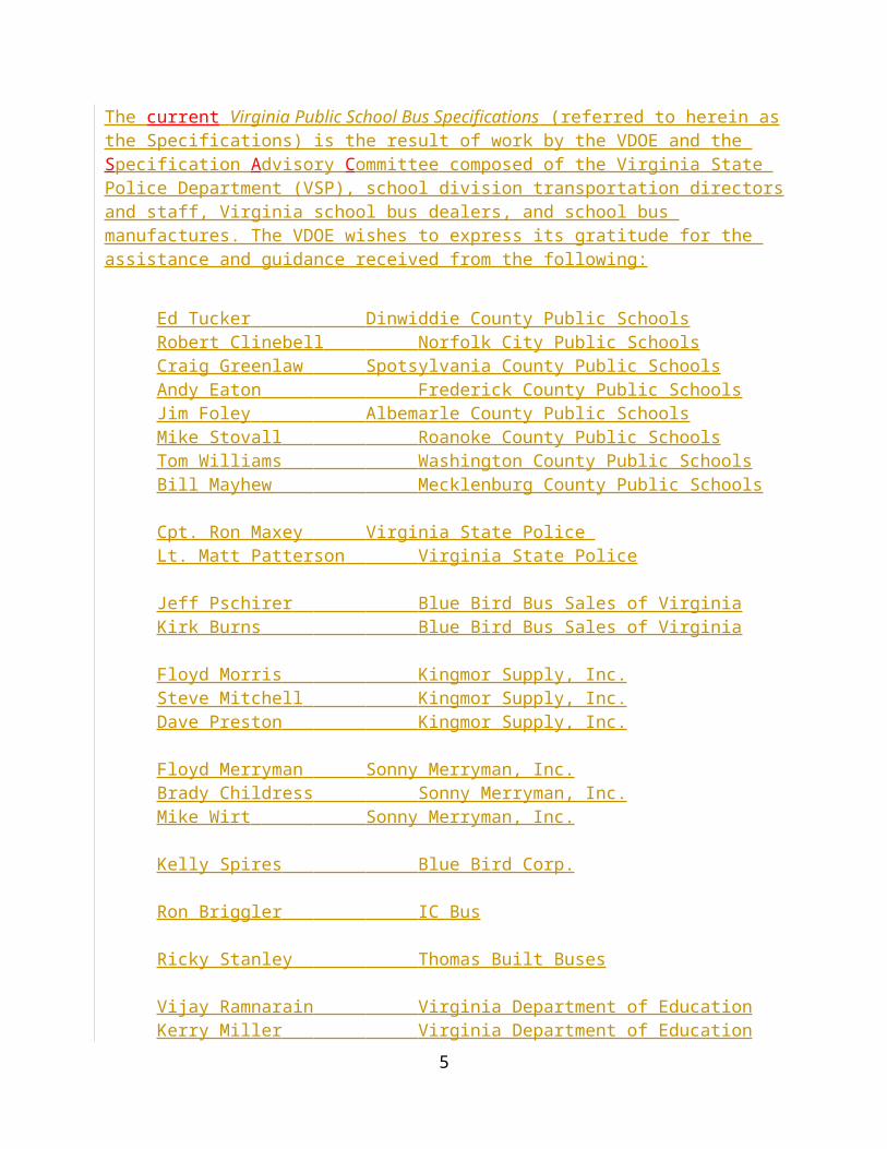
The current Virginia Public School Bus Specifications (referred to herein as the Specifications) is the result of work by the VDOE and the S pecification A dvisory C ommittee composed of the Virginia State Police Department (VSP), school division transportation directors and staff, Virginia school bus dealers, and school bus manufactures. The VDOE wishes to express its gratitude for the assistance and guidance received from the following:
Ed Tucker Dinwiddie County Public SchoolsRobert Clinebell Norfolk City Public SchoolsCraig Greenlaw Spotsylvania County Public SchoolsAndy Eaton Frederick County Public SchoolsJim Foley Albemarle County Public SchoolsMike Stovall Roanoke County Public SchoolsTom Williams Washington County Public SchoolsBill Mayhew Mecklenburg County Public Schools
Cpt. Ron Maxey Virginia State Police Lt. Matt Patterson Virginia State Police
Jeff Pschirer Blue Bird Bus Sales of VirginiaKirk Burns Blue Bird Bus Sales of Virginia
Floyd Morris Kingmor Supply, Inc.Steve Mitchell Kingmor Supply, Inc.Dave Preston Kingmor Supply, Inc.
Floyd Merryman Sonny Merryman, Inc.Brady Childress Sonny Merryman, Inc.Mike Wirt Sonny Merryman, Inc.
Kelly Spires Blue Bird Corp.
Ron Briggler IC Bus
Ricky Stanley Thomas Built Buses
Vijay Ramnarain Virginia Department of EducationKerry Miller Virginia Department of EducationJackie Herring Virginia Department of EducationHarold Grimes Virginia Department of Education
4
General Information
1. All public school and MFSAB buses (bodies and chassis) and school activity buses used to transport children to and from school public schools or school-related events purchased, leased or contracted for by any public school board in Virginia, on or manufactured on or after the effective date of this document, as specified in 8VAC20-70-460, shall:
aA. Meet or exceed the minimum requirements of these the Specifications;.
bB. Meet all applicable Federal Motor Vehicle Safety Standards; (FMVSS).
C. Meet or exceed the current National School Transportation Specifications and Procedures (also referred to herein as the National Specifications) except when in conflict with the requirements herein. In such cases, the requirements requirement specified in this document shall prevail; and.
dD. Meet or exceed applicable National Fire Protection Association (NFPA) codes and safety standards for alternative fuel vehicles.
2. The requirements specified herein are the minimum requirements for public school and MFSAB buses in Virginia. The date used to determine the applicability of these the Specifications shall be defined as the bus manufactured date the vendor receives the purchase order or signs a valid sales contract with the purchaser.
3. Any variation from the Specifications, in the form of additional equipment or changes in style of equipment, without prior approval of the Department of Education (DOE), VDOE, is prohibited.
4. The VDOE may request the school bus (body and chassis) manufacturer to certifythat its their product meets these minimum standards on items which are not covered by FMVSS certification requirements of 49 CFR, Part 567,Certification.
5
General Requirements for Alternative Fuel Public School Buses
1. All alternative fuel public school buses shall be capable of traveling not less than 200 miles with a full load, except those powered solely by electricity shall be capable of traveling not less than 80 miles.
[2.] Natural gas powered vehicles public school buses shall be equipped with an interior/exterior gas leak detection system and fire suppression system as outlined in Item item 15.A.
2.[3.] All materials and assemblies used to transfer or store alternative fuels shall be installed outside the passenger/driver compartment.
[4.] The manufacturer supplying the alternative fuel equipment must shall provide the owner and operators with the adequate training and certification in fueling procedures, schedule of maintenance, troubleshooting and repair of alternative fuel equipment.
[5.] All fueling equipment shall be designed specifically for fueling motor vehicles public school buses and shall be certified by the manufacturer as meeting all applicable federal, state and industry standards.
[6.] All on On board fuel supply containers shall meet all appropriate requirements of the American Society of Mechanical Engineers (ASME) code, U.S. Department of Transportation (DOT) regulations or and applicable FMVSS and NFPA standards.
3.[7.] All fuel supply containers shall be securely mounted to withstand a static force of eight times their weight in any direction.
[8.] A positive quick acting (1/4 one-fourth turn) shut-off control valve shall be installed in each gaseous fuel supply line, as close as possible to the fuel supply containers. The valve controls shall be placed in a location easily accessible without the use of tools, and shall be operable from the exterior of the vehicle. bus. The location of the valve controls shall be clearly marked on the exterior surface of the bus.
4.[9.] An electrical grounding system shall be required for the grounding of the fuel system during maintenance-related venting.
[10.] Biodiesel must conform to the specifications of the American Society for Testing and Materials (ASTM) 6751, (Biodiesel Standards.).
[11.] The manufacturer of alternative fueled vehicles fuel public school buses shall provide written certification to the purchaser and the Virginia Department of Education VDOE that the alternative fuel installation, parts, and materials meet the National Fire Protection
6
Association NFPA and other applicable standards, including all alternative fuel requirements of the Virginia School Bus Specifications.
Section 2
Virginia School Bus Specifications EffectiveDecember 21, 2013
DEFINITIONS
1. Public School Buses:
TYPE A:
Type “A” school bus is a conversion bus constructed utilizing a cutaway front-section vehicle with a left side driver’s driver’s door. This definition includes two classifications: Type A1, with Gross Vehicle Weight Rating (GVWR) 14,500 pounds or less; and Type A2 with a GVWR greater than 14,500 pounds and but less than or equal to 21,500 pounds. Both Type A1 and A2 buses shall be equipped with dual rear wheels (DRW).
TYPE B:
Type “B” school bus is constructed utilizing a body on a stripped chassis. The entrance door is behind the front wheels. This definition includes two classifications: Type B1, with a GVWR of 10,000 pounds or
less, designed for carrying more than 10 persons and Type B2, with a GVWR greater than 10,000 pounds.
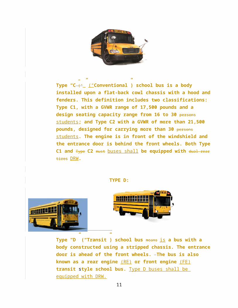
TYPE C:
7
Type “C”(“” (“Conventional”) school bus is a body installed upon a flat-back cowl chassis with a hood and fenders. This definition includes two classifications: Type C1, with a GVWR range of 17,500 pounds and a design seating capacity range from 16 to 30 persons students; and Type C2 with a GVWR of more than 21,500 pounds, designed for carrying more than 30 persons students. The engine is in front of the windshield and the entrance door is behind the front wheels. Both Type C1 and Type C2 must buses shall be equipped with dual rear tires DRW.
TYPE D:
Type “D” (“Transit”) school bus means is a bus with a body constructed using a stripped chassis. The entrance door is ahead of the front wheels. The bus is also known as a rear engine (RE) or front engine (FE) transit style school bus. Type D buses shall be equipped with DRW.
8
Multifunction School Activity Bus:
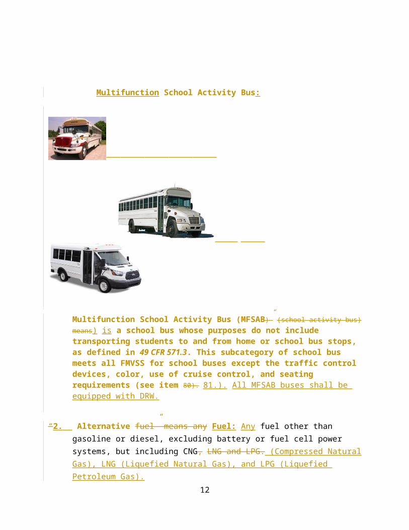
Multifunction School Activity Bus (MFSAB)” (school activity bus) means) is a school bus whose purposes do not include transporting students to and from home or school bus stops, as defined in 49 CFR 571.3. This subcategory of school bus meets all FMVSS for school buses except the traffic control devices, color, use of cruise control, and seating requirements (see item 80). 81.). All MFSAB buses shall be equipped with DRW.
“2. Alternative fuel” means any Fuel: Any fuel other than gasoline or diesel, excluding battery or fuel cell power systems, but including CNG, LNG and LPG. (Compressed Natural Gas), LNG (Liquefied Natural Gas), and LPG (Liquefied Petroleum Gas).
[1.] “ASME Code” means section VIII and IX of the American Society of Mechanical Engineers.
[2.] “CFR” means Code of Federal Regulations.
[3.] “CNG” means compressed natural gas.
[4.] “DOT” means the U. S. Department of Transportation.
[5.] “FMCSR” means Federal Motor Carrier Safety Regulations as found in the Code of Federal Regulations.
9
[6.] “FMVSS” means the Federal Motor Vehicle Safety Standards as found in the Code of Federal Regulations.
3. Fuel supply container” Supply Container (or “fuel cylinder” means aFuel Cylinder”): A container or cylinder installed on a vehicle public school bus to supply fuel for the propulsion system of the vehicle.
4. Fuel system” means the System: The fuel supply container or cylinder, supply lines, and all ancillary fuel equipment.
[7.] “LNG” means liquefied natural gas.
[8.] “LPG” means liquefied petroleum gas.
5. Non-Sequential Operations: The system of red and amber signal lamps designed so that red lamps are activated whenever the passenger entrance doors open, regardless of whether the amber lamps have been activated.
6. Gross Vehicle Weight: The wet weight, plus body weight, plus driver’s weight of 150 lbs, plus weight of maximum seated pupil load based on not less than 120 lbs per pupil.
7. Liquid fuel” means any Fuel: Any fuel that is in a liquid state under normal ambient atmospheric conditions of temperature and pressure.
10
A cronyms
A list of acronyms and their definitions, used in this document:
1. ABS Anti-lock Braking System
2. AMPS Amperes
3. ASME American Society of Mechanical Engineers, §§ VIII, IX
4. ASTM American Society for Testing and Materials
5. BOE Virginia Board of Education
6. BTU British Thermal Unit
7. “C” Celsius
8. CCA Cold Cranking Amperes
9. CFR Code of Federal Regulations
10. CFM Cubic Feet per Minute
11. CDL Commercial Driver License
12. CNG Compressed Natural Gas
13. dB Decibel
14. DOT United States Department of Transportation
15. DRL Daytime Running Lights
16. DRW Duel Rear Wheels
17. “F” Fahrenheit
18. FMCSR Federal Motor Carrier Safety Regulations
19. FMVSS Federal Motor Vehicle Safety Standards
20. “g” Gravity-force
21. GALS Gallons
22. GAWR Gross Axle Weight Rating
23. GRD Ground
11
Acronyms (continued)
24. GVW Gross Vehicle Weight (wet weight, + body weight, + driver’s weight of 150 lbs, + weight of maximum seated pupil load based on not less than 120 lbs per pupil)
25. GVWR Gross Vehicle Weight Rating
26. HP Horse Power
27. LBS Pounds
28. LNG Liquefied Natural Gas
29. LPG Liquefied Petroleum Gas
30. MFSAB Multifunction School Activity Bus
31. MPH Miles per Hour
32. National Specifications National School Transportation Specifications and Procedures
33. NFPA” means the National Fire Protection Association.
34. NSBY National School Bus Yellow
35. OEM Original Equipment Manufacturer
36. “P” Passenger Endorsement on Commercial Driver License
37. RPM Revolutions per Minute
38. “S” School Bus Endorsement, Commercial and Regular Driver License
39. SAE Society of Automotive Engineers
40. SBMTC School Bus Manufacturers Technical Council
41. Specifications Virginia School Bus Specifications
42. TRA Tire and Rim Association, Inc., Standards
[9.] “Non-Sequential Operations” means the system of red and amber signal lamps designed so that red lamps are activated whenever the entrance doors open, regardless of whether the amber lamps have been activated.
12

Acronyms (continued)
43. UL Underwriters Laboratories, Inc.
44. VDOE Virginia Department of Education
45. VSP Virginia State Police Department
SPECIFICATIONS FOR PUBLIC SCHOOL BUSESEffective Month /Day, 201 9
SPECIFICATIONS FOR THE PUBLIC
SCHOOL BUS CHASSIS
Effective December 21, 2013
[1.] Air Cleaner .
A. The engine intake air cleaner system shall be furnished and properly installed by the chassis manufacturer to meet the engine manufacturer’s specifications.
B. An air cleaner restriction indicator shall be furnished and installed by chassis manufacturer.
[2.] Alternator .
[A.] All public school buses shall be equipped with a heavy duty truck or bus type alternator having a minimum output rating of 130 amperes (amps) for Type A buses, and 160 amperes 200 amps for Type B Types C and above, D buses. The alternator shall be capable of producing a minimum of 50 percent of its maximum rated output at the engine manufacturer’s recommended idle speed.
13
C.[B.] Buses equipped with electrically powered wheelchair lift, air conditioning or other accessories may be equipped with a device that monitors the electrical system voltage and advances the engine idle speed when the voltage drops to, or below, a pre-set level.
D.[C.] Belt drive shall be capable of handling the rated capacity of the alternator with no detrimental effect on other driven components. Direct/gear-drive alternator is permissible in lieu of belt drive.
3. Axles.
[A.] The front and rear axle axles and suspension systems shall have a gross axle weight rating Gross Axle Weight Rating (GAWR) at ground commensurate with the respective front and rear weight loads that will be imposed by the bus.
A.[B.] Rear axle shall be single speed, full-floating type.
4. Battery.
A. The storage batteries shall have minimum cold cranking capacity rating (cold cranking amps, or cca) equal to the cranking current required for 30 seconds at 0 degrees (°) Fahrenheit (F) and a minimum reserve capacity rating of 120 minutes at 25 amps. Higher capacities may be required, depending upon optional equipment and local environmental conditions.
[B.] Batteries shall be mounted in a slide out tray on the left side of the body in a compartment designed for storage batteries storage. When in the stored position, the tray shall be retained by a securing mechanism capable of holding the tray [with battery(ies)] batteries in position when subjected to a 5g5 gravity (g) load from any direction. The battery compartment door or cover, if separate from the tray, shall be hinged at the front or top. It shall be secured by a positive operated latching system or other type fastener. The door may be an integral part of the battery slide tray. The door or cover must shall fit tightly to the body, and not present presents sharp edges or snagging points. Battery cables shall meet Society of Automotive Engineers (SAE) requirements. Battery cables and shall be of sufficient length to allow the battery tray to fully extend.
[C.] Exception: Type A units Batteries public school bus batteries may be located in standard manufacturer’s position.
14
D. Buses may be equipped with a battery shut-off switch. The switch is to be placed in a location not readily accessible to the driver or passengers.
5. Brakes.
[A.] Four-wheel brakes, adequate at all times to control bus when fully loaded, shall be provided in accordance with Federal Motor Vehicle Safety FMVSS.
[B.] The chassis brake system shall conform to the provisions of Federal Motor Vehicle Safety Standards (FMVSS) 105 (Hydraulic and Electric Brake Systems), 106 (Brake Hoses), and 121 (Air Brake Systems) as applicable.
A.[C.] Chassis shall be equipped with auxiliary brakes capable of holding vehicle on any grade on which it is operated under any conditions of loading on a surface free from snow or ice. Operating controls of such auxiliary brakes shall be independent of operating controls of service brakes.
[D.] Buses Public school buses having full compressed air systems shall be equipped with a minimum 13.2 cubic feet per minute (cfm) engine oil-fed air compressor.
1. Air supply for air compressor shall be taken from the clean side of engine air cleaner system.
2. A desiccant type air dryer with automatic purge and drain cycle and a heating element shall be installed on all air brake buses.
3. Air brake systems shall include system for anti-compounding of the service and parking brakes.
Buses
B. Public school buses using hydraulic brakes shall have power assist brakes. Hydraulic line pressure shall not exceed recommendation of chassis or brake manufacturer.
C.[E.] All non-parking pawl transmissions shall incorporate a park brake interlock that requires the service brake to be applied to allow release of the parking brake.
15
6. Bumper, Front.
[A.] The front bumper on buses of Type A-2 (with GVWR greater than 14,500 pounds), Type B, Type Types A2, C, and D public school buses shall be pressed steel channel, painted black at least 3/16 three-sixteenths inches thick and not less than 8 eight inches wide (high). It shall extend beyond the forward-most part of the body, grille, hood and fenders and shall extend to the outer edges of the fenders at the bumper’s top line. Type A A1 public school buses having a GVWR of 14,500 pounds or less may be equipped with an Original Equipment Manufacturer (OEM-) supplied front bumper. The front bumper shall be of sufficient strength to permit being pushed by another vehicle on a smooth surface with a 5 five degree (8.7 percent) grade, without permanent distortion. The contact point on the front bumper is intended to be between the frame rails, with as wide a contact area as possible. If the front bumper is used for lifting, the contact points shall be under the bumper attachments to the frame rail brackets unless the manufacturer specifies different lifting points in the owner’s manual. Contact and lifting pressures should be applied simultaneously at both lifting points.
[B.] The front bumper shall be of sufficient strength to permit pushing a vehicle of equal gross vehicle weight, per Section B, (GVW) without permanent distortion to the bumper, chassis or body.
C. The bumper shall be designed or reinforced so that it will not deform when the bus is lifted by a chain that is passed under the bumper (or through the bumper if holes are provided for this purpose) and attached to both tow hooks/eyes. For the purpose of meeting this specification, the bus shall be empty and positioned on a level, hard surface and both tow hooks/eyes shall share the load equally.
7. Clutch.
[A.] Torque capacity shall be equal to or greater than the engine torque output. Clutch facing shall be non-asbestos.
A.[B.] A starter interlock shall be installed to prevent actuation of the starter if the clutch pedal is not depressed.
8. Color.
16
[A.] Chassis, including wheels, front bumper, rails and lettering shall be black. Backs of mirrors should be non-gloss black. The balance of the bus should be yellow.
[B.] Hood, Cowl and Fenders shall be NSBY.
B. All paint shall meet the be lead-free standards.
C. Exception: Activity MFSAB buses shall not be painted NSBY. (See Item 80.) (see item 81.).
9. Drive Shaft.
A. Drive shaft shall be protected by metal guard or guards to prevent it from whipping through floor or dropping to ground if broken.
10. Electrical System.
[A.] Battery. See Item (see item 4..).
[B.] Alternator. See Item (see item 2..).
[C.] Lights and signals. See Item (see item 21..).
[D.] Wiring. See Item 79. (see item 80.).
[E.] Power terminal. : Chassis manufacturer shall provide an electric power source terminal for bus body power connection. Wiring from the power source in wiring terminal shall have a current carrying capacity of 125 amperes amps continuous (minimum four gauge wire). If the bus is to be equipped with Air Conditioning or Wheelchair Lift, current carrying capacity shall be increased to 150 amperes amps continuous.
1. This conductor shall be routed to cover the least distance practicable between points of termination. It should be of continuous size protected by fusible links,
17

fuses, circuit breakers, or a resettable electronic circuit protection device, no more than 24 inches from the battery. The terminal shall be of the single post-type, minimum of one-fourth inch (1/4”) stud and located in an accessible location for service, subject to approval of the Department of Education..
[F.] Light terminal. : The chassis manufacturer shall provide a wire terminal adjacent to or in the under dash area of the left side panel accessible to the body company for connection of rear brake lights, tail lights, turn signal lights, and back-up lights. A terminal strip consisting of individual terminals with each terminal properly identified shall be provided to meet this requirement.
[G.] Fuse. Fuses: All fuses shall be located in fuse block and properly identified for the circuit protected.
A.[H.] Each chassis circuit shall be color-coded and a diagram of the circuits shall be included with the chassis.
[I.] Wiring harness. All conductors from the alternator to the battery shall be continuous in length. The conductors shall be sized to provide at least a 25 percent greater current carrying capacity than the design output of the alternator (minimum four-gauge wire). The conductor between the alternator and the battery shall be routed in a manner that will provide the least distance between points of termination. A separate ground conductor from alternator to engine shall be provided (minimum four-gauge).
[J.] Buses using multiplexed electrical systems may meet the intent of these specifications without the use of specified equipment, subject to the approval of the Department of Education.
11. Electronic Engine Road Speed Limiter.
[A.] An electronic engine road speed limiter shall be provided and set to limit engine road speed not to exceed the maximum revolutions per minute as recommended by the engine manufacturer. Bus road speed shall not exceed a maximum of to 60 miles per hour. (MPH) on all public school buses. Cruise control shall not be installed on public school buses painted NSBY.
12. Engine.
18

[A.] The engine shall be of the internal-combustion, four-stroke cycle type.
B. Vehicles Public school buses equipped with CNG, LPG gaseous or liquid injected, and other gaseous fuels engines must shall be equipped with the valves, valve seats, and other necessary components hardened for the use with such fuels.
13. Exhaust System.
A. Exhaust pipe, muffler, after treatment system, and tail pipe shall be outside the bus body and attached to the chassis so that any other chassis component is not damaged.
B. Size of tail pipe shall not be reduced after it leaves muffler.
C. Exhaust system shall be properly insulated from fuel supply containers and fuel supply container connections by securely attached metal shield at any point where it is 12 twelve inches or less from fuel supply container or tank fuel supply container connections/components.
D. Muffler shall be constructed of corrosion corrosive resistant material.
E. Exhaust shall exit to the rear and opposite side of vehicles with special service entrances. The exhaust on Type A shall exit behind the rear wheel and to the opposite side of the special service entrance.
FE. The tail pipe and after treatment system shall be constructed of 16-gauge steel tubing of equal diameter.
G
F. The tail pipe may be flush with, or shall not extend more than 2 two inches beyond the perimeter of the body for side-exit pipe or the bumper for rear-exit
19
pipe. The exhaust system shall be designed such that exhaust gas will not be trapped under the body of the bus.
HG. The tail pipe shall exit to the left or right of the emergency exit door in the rear of the vehicle under or to through the left side of the bus in front of or behind the rear drive axle. The tail pipe shall not exit beneath any fuel filler location, emergency door or lift door. bumper.
14. Fenders, Front.
A. Total spread of outer edges of front fenders, measured at fender line, shall exceed total spread of front tires when front wheels are in straight-ahead position.
[B.] Front fenders shall be properly braced and free from any body attachment attachments.
15. Fire Suppression Systems (Optional except for natural gas powered vehicles Buses). See General Requirements for Alternative Fuel School Buses in Item 2.)
A. Natural gas-powered public school buses shall be equipped with an
interior/exterior gas leak detection system and an automatic or manual fire suppression system in the engine compartment.
B. All other public school buses may be equipped with a fire suppression system as an option.
C. If equipped with a fire suppression system, it shall be located in the engine compartment.
[D.] The fire suppression system nozzles shall be located in the engine compartment, under the bus, in the electrical panel or under the dash, but they shall not be located in the passenger compartment.
E. The system shall be triggered by electronic activation through a control panel that provides an audible and visual alarm. The control panel shall be located within
20
view and easy reach of the driver. The control panel shall supervise all suppression circuits. The fire suppressant chemical shall be Purple K (dry type), ABC (dry type) or FE-36 (liquid clean agent). A pressure gauge, light or monitor shall be mounted within the driver’s compartment area to monitor the status of the charged chemical canister. If a light or monitor is utilized, a pressure gauge must still be provided at the charged chemical canister. The fire suppression system shall be capable of being activated whether the engine is running or not. The complete fire suppression system shall be warranted for a minimum of one year. The fire suppression manufacturer must shall supply a written certification report that is specific to each application of installation. The fire suppression system shall not have a vehicle shut down system. A placard shall be placed in clear view of the driver that reads “IN CASE OF FIRE, STOP VEHICLE, SHUT OFF ENGINE””, and any necessary instruction instructions providing further driver directions.
F. Option: Control panel can may have a manual means of actuation accessible to the driver.
16. Frame.
A. Frame lengths shall be established in accordance with the design criteria for the complete vehicle.
B. Making holes in top or bottom flanges or side units of the frame and welding to the frame shall not be permitted except as provided or accepted by the chassis manufacturer.
C. Frames shall not be modified for the purpose of extending the wheel base.
D. Any secondary manufacturer that modifies the original chassis frame shall provide a warranty at least equal to the warranty offered by the original equipment manufacturer (OEM) OEM, and shall certify that the modification and other parts or equipment affected by the modification shall be free from defects in material and workmanship under normal use and service intended by the OEM.
17. Fuel Supply Container.
21
[A.] Fuel supply container shall be rated for the appropriate passenger capacity of the vehicle, per manufacturer and FMVSS, but shall not be less than 30 gallons. 25-gals for Type A public school buses and not less than 30-gals for Type C and D public school buses. The fuel supply container for alternative fuels shall be rated in the gasoline or diesel gallon equivalents. The fuel supply container shall be filled and vented to the outside of the body, and the fuel filler should shall be placed on the right side in a location where accidental fuel spillage will not drop or drain on any part of the exhaust system. CNG and LPG cylinders shall have pressure relief device vented to the outside of the body and the fuel filler should shall be placed on the right side in a location where access to filler port with high pressure fill connection can be made easily with filler hose.
A.[B.] Fuel lines shall be mounted to the chassis frame in such a manner that the frame provides the maximum possible protection from damage.
[C.] Fuel supply container may be mounted between the frame rails or outboard on the right side of the vehicle. (Alternative fuel supply containers, see Item 17.F.)
B.[D.] The actual draw capacity of each fuel supply container shall be a minimum of 83 percent of the fuel supply container capacity. Alternative fuel capacity shall be equal to the gasoline or diesel equivalent.
[E.] Exception: Type A Vehicles Special needs public school buses will that are Specially equipped buses may allow for a left side fuel filler.
[F.] Installation The installation of alternative fuel supply containers and fuel systems shall comply with all applicable Federal Motor Vehicle Safety Standards (FMVSS),, CFRs, all applicable fire codes, all applicable DOT requirements and applicable standards of the National Fire Protection Association. NFPA. All alternative fuel supply containers shall be securely mounted and protected to withstand a static force of eight times their weight from any direction. Vehicle manufacturer School bus manufacturers or installers of alternative fuel system must systems shall provide written certification that all applicable standards have been met. No parts of the fuel supply containers shall be mounted in the drivers or passengers compartment of the bus. No fuel supply container shall be mounted above or on top of the bus. Fuel supply containers and supply lines and fittings shall be steel and meet ASME codes.
18. Heating System, provision for.
22
[A.] The chassis engine shall have plugged openings for the purpose of supplying hot water for the bus heating system. The opening shall be suitable for attaching ¾ three-fourth inch pipe thread/hose connector. The engine shall be capable of supplying water having a temperature of at least 170 ° F at a flow rate of 50 pounds per minute at the return end of 30 feet of one-inch inside diameter automotive hot water heater hose. ( (reference: School Bus Manufacturers Technical Council (SBMTC)), Standard Code for Testing and Rating Automotive Bus Hot Water Heating and Ventilating Equipment.)).
B. Exception: Type A public school buses shall be use manufacturer’s standard heating system.
19. Horn.
A. The Each public school bus shall be equipped with a horn(s) of standard make with the horn(s) capable of producing a complex sound in bands of audio frequencies between 250 and 2,000 cycles per second, and tested in accordance with SAE J377, (Horn – Forward Warning – Electric –Performance, Test, and Application.).
20. Instrument and Instrument Panel.
A. Chassis shall be equipped with the following instruments and gauges:
[1.] Speedometer which will show speed;.
[2.] Odometer which will show accrued mileage, including tenths of miles,; tenths of miles can be accrued with trip odometer;.
[3.] Ammeter or voltmeter with graduated scale;.
[4.] Oil pressure gauge;.
23
[5.] Water Coolant temperature gauge;.
[6.] Fuel gauge;.
[7.] High beam headlamp indicator; and.
1.[8.] Tachometer.
B. All instruments or gauges shall be mounted on instrument panel in such manner that each is clearly visible to driver in normal seated position. Lights in lieu of gauges are not acceptable.
[C.] Exception: Type A vehicles the public school bus ammeter or voltmeter and its wiring are to shall be compatible with generating capacity. Tachometer A tachometer is not required.
[A.] Multifunction gauges must have prior approval of the Department of Education.
21. Lights and Signals.
[A.] Each chassis shall be equipped with not less than two headlights, beam controlled, and stop and tail lights, and two front turn signal lamps mounted on front fenders. Front turn signal lamps on Type D bodies shall be the same as the rear turn signals unless the turn signals are incorporated as a part of the headlight assemblies or otherwise incorporated into the front end design as approved by the Department of Education VDOE.
A.[B.] Lights shall be protected by fuse or circuit breakers.
[C.] Self-canceling directional signal switch shall be installed by the chassis manufacturer. The directional signals shall activate only when ignition is in “on ON” position.
[D.] Daytime Running Lights (DRL) are shall be required.
24
[E.] Brake air pressure gauge (air brakes), brake indicator lamp (vacuum/hydraulic brakes), or brake indicator lamp (hydraulic/hydraulic) are shall be required.
[F.] Turn signal indicator is shall be required.
[G.] Glow-plug indicator Engine pre-heater lamp is required, where appropriate.
[H.] Instruments and controls must shall be illuminated as required by FMVSS 101 (Controls and Displays).
22. Oil Filter.
A. An oil filter with a replaceable element shall be provided and connected by flexible oil lines if it is not a built-in or an engine-mounted design. The oil filter shall have a capacity in accordance with the engine manufacturer’s recommendation.
23. Openings.
A. All openings in floorboard or firewall between chassis and passenger-carrying compartment, such as for gearshift lever and auxiliary brake lever, shall be sealed.
24. Passenger Load.
Gross vehicle weight (
A. GVW) (i.e., wet weight, plus body weight, plus driver’s weight of 150 pounds, plus weight of maximum seated pupil load based on not less than 120 pounds per pupil) shall not exceed maximum gross vehicle weight rating GVWR as established by manufacturer.
25
B.[A.] Actual GVW shall not exceed the chassis manufacturer’s GVWR for the chassis, nor shall the actual weight carried on any axle exceed the chassis manufacturer’s Gross Axle Weight Rating (GAWR).
25. Retarder System (Optional).)
A. A retarder system, if used, shall limit the speed of a fully loaded school bus to 19.0 mph on a 7 percent grade for 3.6 miles.
26. Shock Absorbers.
A. All public school and MFSAB buses shall be equipped with front and rear double-acting shock absorbers compatible with manufacturer’s rated axle capacity.
27. Springs. and Suspension Systems
A. Springs or suspension assemblies shall be of ample resiliency under all load conditions and of adequate strength to sustain loaded bus without evidence of overload.
[B.] Springs or suspension assemblies shall be designed to carry their proportional share of gross vehicle weight GVW.
B.[C.] Rear springs shall be of progressive, variable, parabolic or air ride type.
C.[D.] Stationary eye of the front spring shall be protected by full wrapper leaf in addition to main leaf.
[E.] The capacity of springs or suspension assemblies shall be commensurate with the chassis manufacturer’s GVWR and chassis specification minimums.
F. Exception: Type A vehicles springs that are regular equipment on vehicle to be purchased may be used.
26
28. Steering Gear.
A. Steering gear shall be approved by chassis manufacturer and designed to assure safe and accurate performance when vehicle is operated with maximum load and maximum speed.
[B.] No changes shall be made in steering apparatus that are not approved by chassis manufacturer.
B.[C.] There shall be clearance of at least two inches between steering wheel and cowl instrument panel, windshield, or any other surface.
C.[D.] Power steering is required and shall be of the integral type with integral valves.
E. The steering system shall be designed to provide a means for lubrication of all wear-points that are not permanently lubricated.
29. Tires and Rims.
[A.] Tire and rim sizes, shall be based upon current standards of The Tire and Rim Association, Inc. (TRA), shall be required.).
A.[B.] Total weight imposed on any tire shall not be above the current standard of the TRA.
[C.] Dual rear tires DRW shall be provided on all vehicles public school buses.
B. All tires on vehicles public school buses shall be of the same size and shall meet or exceed the load range rating of the TRA for required GAWR.
C.[D.] Spare tire, if required, shall be suitably mounted in accessible location outside passenger compartment.
27
30. Towing Attachment Points.
A. Front and/or rear towing devices (i.e., tow hooks, tow eyes, or other designated towing attachment points) shall be furnished to assist in the retrieval of buses that are stuck and/or for towing buses when a wrecker with a “wheel lift” or an “axle lift” is not available or cannot be applied to the towed vehicle.
B. Towing devices shall be attached to the chassis frame either by the chassis manufacturer or in accordance with the chassis manufacturer’s specifications.
C. Each towing device shall have a strength rating of 13,500 pounds each for a combined rating of 27,000 pounds with the force applied in the rearward direction, parallel to the ground, and parallel to the longitudinal axis of the chassis frame rail.
D. The towing devices shall be mounted such that they do not project forward of the front bumper or rearward of the rear bumper.
Note: E. Type A public school buses are exempt from this requirement for front tow hooks or eyes due to built-in crush zones. Tow eyes or hooks shall be furnished and attached so they do not project beyond the front bumper.
31. Transmission.
[A.] Mechanical type transmission shall be synchromesh except first and reverse gears. Its design shall provide not less than four five forward and one reverse speeds. With five-speed transmission,; fifth gear shall be direct.
A.[B.] Automatic transmissions are permissible when equipped with a parking pawl or approved parking brake system.
[C.] Automatic transmissions incorporating a parking pawl shall have a transmission shifter interlock controlled by the application of the service brake to prohibit
28
accidental engagement of the transmission. All non-parking pawl transmissions shall incorporate a park brake interlock that requires the service brake to be applied to allow release of the parking brake. (see item 5.F.).
32. Turning Radius.
[A.] Chassis with a wheel base of 264 inches or less shall have a right and left turning radius of not more than 42 ½ .5 feet, curb to curb measurement.
[B.] Chassis with a wheel base over 264 inches shall have a right and left turning radius of not more than 44 ½ .5 feet, curb to curb measurement.
33. Weight Distribution.
A. Shall be established by chassis manufacturers’ engineering department.
34. Wheels.
A. Disc wheels are required.
SPECIFICATIONS FOR THE PUBLIC SCHOOL BUS BODY
35. Aisle.
A. Minimum clearance of all aisles, including aisle (or passageway between seats) leading to emergency door shall be 12 inches. Aisles shall be unobstructed at all times.
36. Back-up Alarm.
29
[A.] An automatic audible alarm shall be installed behind the rear axle and shall comply with the published SAE J994b (Backup Alarm Standards (SAE J994b),) providing a minimum of 112 dBA, decibels (dB), or shall have a variable volume feature that allows the alarm to vary from 87 dBA dB to 112 dBA dB sound level, staying at least 5 dBA dB above the ambient noise level.
37. Body Sizes.
[A.] Sizes are based on knee-room clearance between rows of forward-facing seats, overall width, center aisle width, and average rump width.
37. Bumper, Rear.
[A.] Rear bumper shall be of pressed steel channel at least 3/16 three sixteenth of an inch by 9 ½ .5 inches.
A.[B.] It shall be wrapped around back corners of bus. It shall extend forward at least 12 inches, measured from rear-most point of body at floor line.
B.[C.] Bumper shall be attached to chassis frame in such manner that it may be easily removed, shall be so braced as to develop full strength of bumper section from rear or side impact, and shall be so attached as to prevent hitching of rides.
C.[D.] Rear bumper shall extend beyond rear-most part of body surface at least one inch, measured at floor line.
[E.] Exception: Type A vehicles public school buses - Rear bumper shall be standard type furnished by chassis manufacturer as part of chassis on conversions. Body manufacturer will furnish bumper on cutaway chassis.
38. Child Check System
A. All public school buses shall be equipped with an electronic audible and visual warning device that requires driver deactivation after the driver walks to the rear of the bus checking for children.
30

39. Color.
[A.] School The public school bus body including hood, cowl, external speakers and fenders shall be painted uniform color National School Bus Yellow (NSBY). Prior to the application of the finish coats to the bus body, hood and cowl, external speakers and fenders, all surfaces shall be cleaned of grease, foreign matter, excessive body caulking, sealing material and treated as per paint manufacturer’s recommendation for proper adhesion and painted NSBY.
A.[B.] Grill shall be NSBY, silver, or gray, if painted; otherwise it shall be chrome or anodized aluminum.
[C.] Rear bumper, body trim, and rub rails shall be painted black. Must meet color requirements specific to bus. (See “Bus Chassis” Item 8 for specific specifications.) (see item 8.).
B.[D.] The roof of the public school bus may be painted white extending down to the drip rails on the sides of the body except that front and rear roof caps shall remain NSBY.
[E.] All paint shall meet the be lead-free standards..
[F.] Paint shall be applied for a total dry thickness of at least 1.8 mils over all painted surfaces.
G. Exception: Activity bus Activity The public MFSAB bus shall not be painted NSBY. Bumpers, body trim and rub rails may be painted a different color other than black. (See Item 80.) (see item 81.).
H. Retro-reflective tape. Material material shall be Type V or better, as determined by the American Society of Testing Materials (ASTM: D4956-90).“ (Standard specifications Specifications for reflectivesheeting Reflective Sheeting
for traffic control.” Traffic Control).
31
[1.] The rear of the public school bus body shall be marked with strips of retro- reflective NSBY material to outline the perimeter of the back of the bus using material which conforms with to the requirements of FMVSS 131 (School Bus Pedestrian Safety Devices, Table 1). The perimeter marking of rear emergency exits per FMVSS 217 (Bus Emergency Exits and Window Retention and Release), and/or the use of retro reflective “SCHOOL BUS” signs partially accomplishes the objective of this requirement. To complete the perimeter marking of the back of the bus, strips of retro-reflective NSBY material a minimum of 1” one inch and a maximum of 2” two inches in width, shall be applied horizontally above the rear windows and above the rear bumper, extending from the rear emergency exit perimeter, marking outward to the left and right rear corners of the bus. Vertical strips shall be applied at the corners connecting these horizontal strips.
1.[2.] “SCHOOL BUS” signs shall be marked with retro reflective NSBY material comprising background for lettering of the front and/or rear “SCHOOL BUS” signs.
[3.] Sides of the public school bus body shall be marked with a minimum of 1” one inch and a maximum of 2” two inches in width retro reflective NSBY material, extending the length of the bus body and located (vertically) between the floor line and the beltline.
I. The back of all mirrors shall be non-gloss black.
40. Communication and Camera Systems (Optional).
[A.] Communication systems. If communication systems are used on school buses, the systems shall be subject to written policies adopted by the local school board. Installation shall be subject to the Department of Education fleet assessment.
[B.] Communication Systems.
1. The radio mounting shall be in the driver’s compartment in a safe, secure location, so as not to interfere with normal bus operation.
2. Mounting shall be permanent. Temporary mountings will not be acceptable.
32
3. Wiring shall be protected by a proper fuse or circuit breaker and permanently connected to an accessory circuit shut off by ignition switch. Plug-in type connections are not acceptable.
4. Antenna shall be permanently mounted so as not to interfere with driver’s vision of roadway. Antenna lead-in cable shall be permanently secured with the proper clamps, grommets, and sealant. Antenna cable may not pass through window opening.
B. Public address system. Address System.
1. For use by driver, the system contains shall contain an inside speaker and/or an external speaker that is of special use when driver needs to caution pupils about surrounding dangers at school bus stops. Inside speakers shall be recessed type.
C. AM/FM radios, cassette players or Radio, CD players. If AM/FM radios, cassette players, or CD players are installed, they shall Player.
1. Shall be properly mounted by the body manufacturer or local shop personnel.
2. All wiring shall be properly connected and concealed and any
speakers shall be of recessed type. 3. No internal speakers, other than the driver’s communication
systems, may be installed within 4 feet of the driver’s seat back in its rearmost upright position.
D. Interior Camera. Both Systems.
A. The recording equipment and installation shall be subject to the Department of Education fleet assessment.
33
[1.] The recording equipment shall be The equipment must be installed in an area at the front of the bus.
[2.] The equipment is shall be mounted outside the federal head impact zone, FMVSS 222 (School Bus Passenger Seating and Crash Protection).
[3.] The equipment is shall be located in an area not likely to cause student injury.
[4.] The equipment will shall have no sharp edges or projections.
E. Exterior Camera System Monitors.
1. Exterior view camera systems may be installed to view areas of restricted visibility outside of the public school bus and shall meet the following criteria:
a. Shall not be mounted where it blocks the driver view in any direction.
b. Shall only activate when the bus is in reverse for a rear camera or when the bus is in park or has the turn signals
activated for side cameras.
c. Shall be automatically controlled without requiring driver action.
d. The exterior camera system monitor may be incorporated as part of the interior rear view mirror and shall not interfere with the normal use of the mirror.
F. Stop Arm Video Monitoring Systems.
1. Stop Arm video monitoring systems for passing stopped on public school buses must shall include the minimum system requirements established by the Code of Virginia: a) must.
34
a. The system shall produce live digital and recorded video of vehicles being operated in violation of the Code; b) must of Virginia.
b. The system shall produce a recorded image of the license plate; c) must
c. The system shall record the activation status of at least one warning device (activation of either and/or the red traffic warning lights and the side stop sign) mounted on the public school bus; d), and the time, date, and location of the vehicle when the image is recorded.
1. d. The system shall not obscure the lettering on the side of the bus is not obscured.
2. Must
e. The system shall not impede or block any emergency exits.
3. All wiring must
f. Wiring shall not be mounted on the outside the side of the public school bus and shall not be mounted inside the driver/passenger area.
g. All roof and side mounting locations must shall be sealed to ensure no leaks.
5. System wiring
h. The system shall have separate wiring from any emergency lights, alarms, etc.
6
i. All exterior camera housings must shall be painted national school bus yellow NSBY.
35
7. System operates
j. The system shall operate automatically and does, not require the require driver to activate it activation.
8
k. Vendor/manufacturer must Manufacturer shall provide documentation to the locality that the system is properly mounted and camera(s) are capturing clear video identifying a moving vehicle.
9
l. Vendor/manufacturer must Manufacturer shall warranty the complete system for at least 12 months after the locality school division accepts documentation of mounting.
10
m. Exterior camera(s) must shall be designed to eliminate movement due to vandalism and rough roads.
41. Construction, Type B, Types C , and D Vehicles. Public School Bus es
A. Construction of public school bus body shall meet all requirements of FMVSS 220 (School Bus Rollover Protection), 49 CFR § 571.220, FMVSS 221 (School Bus Joint Strength), 49 CFR § 571.221, and all other applicable federal standards.
B. Construction shall be of prime commercial quality steel, or other material with strength at least equivalent to all steel as certified by bus body manufacturer. All such construction materials shall be fire resistant.
C. Construction shall provide reasonable dust proof and watertight unit.
[D.] Bus body (including Body: The roof bows, body posts, strainers, stringers, floor, inner and outer linings, rub rails and other reinforcements) shall be of sufficient strength to support entire weight of fully loaded vehicle on its top or side if overturned. Bus body as unit shall be designed and built to provide impact and penetration resistance.
36
[E.] Side posts Posts and roof bows. Roof Bows: There shall be a body side post and roof bow fore and aft of each window opening. This may be a continuous bow or two separate pieces effectively joined.
[F.] Floor shall: Shall be of prime commercial quality steel of at least 14-gauge or other metal or other material at least equal in strength to 14-gauge steel. Floor shall be level from front to back and from side to side except in wheel housing, toe board, and driver’s seat platform areas. When plywood is used, it shall be of ½ one-half inch exterior B.B. Grade or equivalent and securely fastened to the existing steel floor.
[G.] Roof strainers. Strainers: Two or more roof strainers or longitudinal members shall be provided to connect roof bows, to reinforce flattest portion of roof skin, and to space roof bows. These strainers may be installed between roof bows or applied externally. They shall extend from windshield header and, when combined with rear emergency doorpost, are to function as longitudinal members extending from windshield header to rear floor body cross member. At all points of contact between strainers or longitudinal members and other structural material, attachment shall be made by means of welding, riveting or bolting.
H. Floor sills. Sills: There shall be one main body sill at each side post and two intermediate body sills on approximately 10 ten inch centers. All sills shall be of equal height, not to exceed three inches. All sills shall extend width of body floor except where structural members or features restrict area. Main body sill shall be equivalent to or heavier than 10-gauge and each intermediate body sill shall be equivalent to or heavier than 16-gauge, or each of all sills shall be equivalent to or greater than 14-gauge. All sills shall be permanently attached to floor. Connections between sides and floor system shall be capable of distributing loads from vertical posts to all floor sills.
I. All openings between chassis and passenger-carrying compartment made due to alterations by body manufacturers shall be sealed. (See Item 60). (see item 61.).
J. A cover shall be provided for the opening to the fuel tank supply container fill pipe.
37
K. A moisture and rustproof removable panel shall be provided in the floor for access to the fuel tank supply container sender gauge. It shall be designed for prolonged use and adequate fastening to the floor.
42. Construction, Type A Vehicles. Public School Bus
A. Construction of public school bus body shall meet all requirements of FMVSS 220 (School Bus Rollover Protection), 49 CFR § 571.220, and all other applicable federal standards.
[B.] Body joints created by body manufacturer shall meet the 60 percent joint strength provision required in FMVSS 221 (School Bus Body Joint Strength), 49 CFR § 571.221, for Type B, Types C, and D public school buses.
B.[C.] Construction shall be of prime commercial quality steel or other material with strength at least equivalent to all steel as certified by bus body manufacturer. All such construction materials shall be fire resistant.
C.[D.] Construction shall provide reasonably dustproof and watertight unit.
[E.] Bus body (including Body: The roof bows, body posts, strainers, stringers, floor, inner and outer linings, rub rails and other reinforcements) shall be of sufficient strength to support entire weight of fully loaded vehicle on its top or side if overturned. Bus body as unit shall be designed and built to provide impact and penetration resistance.
[F.] Floor.: Plywood of ½ one-half inch exterior B.B. Grade or equivalent shall be applied over the existing steel floor and securely fastened. Floor shall be level from front to back and from side to side except in wheel housing, toe board, and driver seat platform areas.
[G.] Roof strainers.: Two or more roof strainers or longitudinal members shall be provided to connect roof bows to reinforce flattest portion of roof skin, and to space roof bows. These strainers may be installed between roof bows or applied externally. They shall extend from windshield header to rear body header over the emergency door. At all points of contact between strainers of longitudinal
38
members and other structural material, attachment shall be made by means of welding, riveting, or bolting.
1. After load as called for in Static Load Test Code has been removed, none of the following defects shall be evident:
a. Failure or separation at joints where strainers are fastened to roof bows;.
b. Appreciable difference in deflection between adjacent strainers and roof bows; or.
c. twisting, buckling, or deformation of strainer cross-section.
[H.] Area between floor and window line shall be restructured inside to include at least four vertical formed reinforcement members extending from floor to window line rail. They shall be securely attached at both ends.
[I.] Rear corner reinforcements. Corner Reinforcements: Rear corner framing of the bus body between floor and window sill and between emergency door post and last side post shall consist of at least one structural member applied horizontally to provide additional impact and penetration resistance equal to that provided by frame members in areas of sides of body. Such member shall be securely attached at each end.
[J.] All openings between chassis and passenger-carrying compartment made due to alterations by body manufacturers shall be sealed. (See Item 60.) (see item 61.).
43. Defrosters.
[A.] Defrosting and defogging equipment shall direct a sufficient flow of heated air onto the windshield, the window to the left of the driver and the glass in the viewing area directly to the right of the driver to eliminate frost, fog and snow. (Exception: The requirements of this standard do not apply to the exterior surfaces of double pane storm windows.)
39
[B.] The defrosting system shall conform to SAE J381, (Windshield Defrosting Systems Test Procedure and Performance Requirements – Trucks, Buses, and Multipurpose Vehicles.).
A.[C.] The defroster and defogging system shall be capable of furnishing heated, outside ambient air, except that the part of the system furnishing additional air to the windshield, entrance door and step well may be the recirculating air type.
[D.] Exception: On Type A vehicle, Types C and D public school buses shall have two auxiliary fan is fans. Auxiliary fans are not required on Type A public school buses.
44. Doors.
[A.] Service Door.
[B.] Service door shall be manually or power-operated, under the driver’s control of driver, and so designed as to afford easy release and to provide a positive latching device, on manual operating doors, to prevent accidental opening.
1. When a hand lever is used, no parts shall come together so as tothat will shear or crush fingers. Manual door controls shall not require more than 25 lbs of force to operate. Power-operated door controls are allowed (see item 44.A.8.).
[1.] Service The door shall be located on the right side of bus, opposite driver and within his the driver’s direct view.
2. Service door shall have minimum horizontal opening of 24 inches and minimum vertical opening of 68 inches.
[3.] Service The door shall be of split-type, outward opening type.
[4.] All door glass shall be approved safety glass. Bottom of each lower glass panel shall not be more than 10 ten inches from the top surface bottom of the bottom step. Top of each upper glass panel when viewed from the
40
interior shall not be more than three inches below the interior door control cover or header pad.
3.[5.] Vertical closing edges shall be equipped with flexible material to protect children’s fingers.
[6.] All doors The door opening shall be equipped with padding at the top of each door opening. Pad. Padding shall be at least three inches wide and one inch thick and extend the full width of the door opening.
[7.] For power-operated entrance service doors, the an emergency release valve, switch or device to release the service door must shall be placed above, to the immediate left, or to the immediate left or right of the entrance door, and must shall be clearly labeled in a color to contrast with the background of the label. The emergency release valve, switch or device shall work in the absence of power.
[C.] Rear Emergency Door Type B, Types C and D vehicles Public School Buses.
4.[1.] Emergency door shall be located in center of rear end of bus.
5.[2.] Rear emergency door shall have minimum horizontal opening of 24 inches and minimum vertical opening of 45 inches measured from floor level.
[3.] Rear emergency door shall be hinged on right side and shall open outward and be equipped with an adequate strap or stop to prevent door from striking lamps or right rear of body. Such strap or stop shall allow door to open at least at a 90-degree angle from closed position.
[4.] Exception: Type D vehicles with rear engines (RE) public school buses - Emergency door shall be located on the left side, shall be hinged on the front side and open outward. Door shall meet all requirements of FMVSS 217 (Bus Emergency Exits and Window Retention and Release), 49 CFR § 571.217.
5. The upper portion of the emergency door shall be equipped with approved safety glazing, the exposed area of which shall be at least 400 square inches. The lower portion of the rear emergency door on Types B, C and D vehicles shall be equipped with a minimum of 350 square inches of
41
approved safety glazing. This glass shall be protected by a metal guard on the inside. This guard shall be free of any sharp edges that may cause injury to passengers.
56. There shall be no steps leading to emergency door.
67. When not fully latched, emergency door shall actuate signal audible to driver by means of mechanism actuated by latch.
78. Words “EMERGENCY DOOR,” both inside and outside in black letters two inches high, painted or vinyl, shall be in compliance with FMVSS 217 (Bus Emergency Exits and Window Retention and Release).
89. The emergency door shall be designed to open from inside and outside bus. It shall be equipped with a slide bar and cam-operated lock located on left side of door and fastened to the door framing.
The slide bar shall be approximately 1 ¼ .25 inches wide and 3/8 three-eighth inch thick and shall have a minimum stroke of 1 ¼ .25 inches. The slide bar shall have a bearing surface of a minimum of 3/4 three-quarter inch with the door lock in a closed position. Control from driver’s seat shall not be permitted. Provision for opening from outside shall consist of non-detachable device so designed as to prevent hitching to, but to permit opening when necessary. Door lock shall be equipped with interior handle and guard that extend approximately to center of door. It shall lift up to release lock.
910. All doors shall be equipped with padding at the top edge of each door opening. Pad shall be at least three inches wide and one inch thick and extend the full width of the door opening.
1011. There shall be no obstruction higher than ¼ one quarter-inch across the bottom of any emergency door opening. Fasteners used within the emergency exit opening shall be free of sharp edges or burrs.
C. Rear emergency door Emergency Door, Type A vehicles Public School Buses.
[1.] Emergency door shall be located in center of rear end of bus and shall be equipped with fastening device for opening from inside and outside body, which may be quickly released but is designed to offer protection against accidental release. Control from driver’s seat shall not be permitted. Provision for opening from outside shall consist of device designed to prevent hitching to but to permit opening when necessary.
42
1.[2.] No seat or other object shall be placed in bus which restricts passageway to emergency door to less than 12 inches.
3. The lower portion of the rear emergency door shall be equipped with a minimum of 350 square inches of approved safety glazing.
D. Security locking system. Locking System.
1. A locking system to lock the emergency door(s) or roof hatch(es) exits and the entrance door may be installed.
2. The system shall meet requirements of FMVSS 217 (Bus Emergency Exits and Window Retention and Release) and be equipped with an interlock in the chassis starting circuit and an audible alarm to indicate when an emergency exit is locked while the ignition switch is in the “on ON” position.
3. A cutoff switch on the interlock circuit or any exit equipped with a lock and hasp shall not be allowed.
4. The entrance service door lock system shall not permit hooking or snagging during passenger egress/ingress.
45. Emergency Equipment.
A. Fire Extinguisher.
[1.] The Each public school bus shall be equipped with one dry-chemical fire extinguisher of at least five-pound capacity with pressure indicator, mounted in extinguisher manufacturer’s bracket of automotive type, and located in full view and in an accessible place in the front of the bus.
[2.] The fire extinguisher shall bear label of Underwriters Laboratories, Inc.,. (UL), showing a rating of 2A 10BC 2-A:10-BC, or greater.
3. Fire The fire extinguisher shall have aluminum, brass, or steel: valves, ; heads,; check stems, ; siphon tubes,; levers,; safety pins,; chain,;
43
handles; and metal hanging brackets. Plastic bracket (plastic shall not be used for those named these parts.).
B. First Aid Kit.
1. Bus Each public school bus shall carry have a removable, Grade A metal, first aid kit, unit-type, mounted in full view and in an accessible place in the front of the bus and identified as a first aid kit.
2. The first aid kit shall contain the following items:
Unit
a. Bandage compress (sterile gauze pads) 4-inch 3
b. Bandage compress (sterile gauze pads) 2-inch 2
c. Adhesive absorbent bandage (nonadhering non-adhering pad) 1 x 3- inch 2
d. Triangular bandage, 40-inch 2
e. Gauze bandage, 4-inch 2
f. Absorbent-gauze compress 1
g. Antiseptic applicator (swab type) 10 per unit 2
(Zephiran Chloride/Green Soap type)
44
h. Bee sting applicator (swab type) 10 per unit 1
i. Pair medical non-latex examination gloves 1
j. Mouth-to-mouth airway 1
C. 1. Bus shall be equipped with a kit containing three reflectorized triangular warning devices meeting requirements of FMVSS 125
(Warning Devices), 49 CFR § 571.125.
2. Kit shall be securely mounted.
D.C. Body Fluid Clean-up Kit.
[1.] Each public school bus shall carry have a removable, Grade A metal or rigid plastic kit, mounted in an accessible place and identified as a body fluid clean-up kit with a directions for use sheet attached to the inside cover.
1.[2.] The body fluid clean-up kit shall be moisture proof and properly mounted or secured in a storage compartment.
2.[3.] Contents shall include, but not be limited to, the following items:
Unit
a. Non-latex gloves 1 pair
[a.] One pick Pick-up spatula or scoop 1
[b.] One face Face mask 1
45
b.[c.] Infectious liquid spill control powder 1 bag
c.[d.] Anti-microbial hand wipes – individually wrapped 2
[e.] Germicidal disinfectant wipes wipe – tuberculocidal 1
d.[f.] Plastic disposal bag with tie 1
D. Seat Belt Cutter.
1. Each public school bus shall be equipped with a durable webbing cutter having a full width handgrip and a protected, replaceable or non-corrodible blade. The required belt cutter shall be mounted in a location accessible to the seated driver in an easily detachable manner.
E. Warning Devices.
1. Each public school bus shall be equipped with a kit containing three reflectorized triangular warning devices meeting requirements of FMVSS 125 (Warning Devices), 49 CFR § 571.125.
2. The warning devices kit shall be securely mounted.
46. Emergency Exits.
A. Each emergency exit shall comply with FMVSS 217 (Bus Emergency Exits and Window Retention and Release), 49 CFR § 571.217, regarding the number of exits, types of exits and location of exits based on the capacity of the vehicle.
1. Side Emergency Exit Doors.
46
a. A dedicated aisle of at least 12 inches in width, referenced to the rear of the emergency exit door is required.
b. Side emergency exit doors shall be hinged on the forward edge.
c. When not fully latched, side emergency exit door shall actuate a signal audible to the driver by means of a mechanism actuated by the latch when the ignition switch is on.
[d.] A security locking system designed to prevent vandalism may be installed provided it meets all specifications of Item (see item 44 .D..).
2. Roof Exits/Vents.
a. All vehicles public school buses shall be equipped with a minimum of one emergency roof exit/vent approved by the Department of Education.
b. When not fully latched, this exit shall actuate a signal audible to the driver by means of a mechanism actuated by the latch when the ignition switch is on.
c. A roof exit/vent security locking system designed to prevent vandalism may be installed provided it meets all specifications of Item 44.D. (see item 44.D.).
d. When a single roof exit is installed, it shall be located as near as practicable to the longitudinal midpoint of the passenger compartment, and shall be installed such that the centerline of the hatch is on the longitudinal centerline of the bus.
e. If two roof exits are utilized, they shall be located as near as practicable to the points equidistant between the longitudinal
47
midpoint of the passenger compartment and the front and the rear of the passenger compartment.
NOTE: No removal or cutting of any roof structural component shall occur during installation. If the installation required by subdivisions 2 d and 2 e of this section cannot be accomplished as described, then prior approval by the Department of Education will be required through a written request from the local school division.
Roof exits/vents shall have rustproof hardware.
e. Roof exits/vents shall be hinged in the front and be equipped with an outside release handle.
[3.] Emergency exit windows Exit Windows.
a. Push-out emergency windows are permissible, if required by FMVSS 217 (Bus Emergency Exits and Window Retention and Release), 49 CFR § 571.217.
b. When not fully latched, the emergency exit window shall actuate a signal audible to the driver by means of a mechanism actuated by the latch.
c. No emergency exit window shall be located directly in front of a side emergency exit door.
d. The rear d. Type D (RE) public school bus emergency window shall have a lifting assistance device that will aid in lifting and holding the rear emergency window open.
48
47. Floor Covering.
A. Floor in under seat area, including tops of wheel housings, driver’s compartment and toe board shall be covered with fire-resistant rubber floor covering or an approved equivalent, having minimum overall thickness of .125 inch. Driver’s compartment and toe board area shall be trimmed with molding strips behind the cowl face line.
[B.] Floor covering in aisle shall be of aisle-type fire resistant rubber or an approved equivalent, nonskid, wear-resistant and ribbed. Minimum overall thickness shall be .1875 inch measured from tops of ribs and have a calculated burn rate of 0.1 or less, using the test methods, procedures and formulas listed in FMVSS 302 (Flammability of Interior Materials). Rubber floor covering shall meet federal specifications ZZ-M71d.
B.[C.] Floor covering shall be permanently bonded to floor, and shall not crack when subjected to sudden changes in temperature. Bonding or adhesive material shall be waterproof and shall be of the type recommended by manufacturer of floor-covering material. All seams shall be sealed with waterproof sealer.
C.[D.] All floor covering seams shall be covered with trim and fastened with screws.
E. On Types B, C, and D public school buses, shall have a flush-mounted, screw-down plate that is secured and sealed shall be provided to provide access to the fuel tank supply container sending unit and/or fuel pump. This plate shall not be installed under flooring material.
48. Handrails.
A. At least 1A. A minimum of one handrail shall be installed. The handrail(s) shall assist passengers during entry or exit, and shall be designed to prevent entanglement, as evidenced by the passing of the NHTSA National Highway Traffic Safety Administration (NHTSA) string and nut test.
49
49. Heating and Air Conditioning Systems.
A. Hot water heaters of fresh air or combination fresh air and recirculating type, with power defrosters, are required.
B. Heaters shall bear nameplate rating affixed by heater manufacturer on top of heater shell.
[C.] Heaters shall be capable of maintaining inside temperature of 50o 50° F, with an outside temperature of 20o 20° F when the bus is loaded to one-half capacity. (SAE test procedure J2233).
[D.] The heater wiring shall be connected to the cold side of the ignition switch through a continuous duty solenoid relay.
C.[E.] The power defroster shall deliver a sufficient amount of heated air distributed through a windshield duct, nozzle or nozzles to defog and de-ice the entire windshield, and to defog the driver’s window. The duct, nozzle, or nozzles shall be designed to prevent objects from being placed in any manner that would obstruct the flow of air.
[F.] Water Types C and D public school buses shall have water circulation cut-off valves in the supply and return lines, a minimum of ¾ three-quarter inch diameter (except Type A), public school buses) and shall be located at or near the engine. A water flow-regulating valve in the pressure line for convenient operation by the driver is also required. All valves shall be ¼ one-quarter turn ball type. The driver and passenger heaters may operate independently of each other for maximum comfort.
D.[G.] Heater hoses, including those in engine compartment, shall be supported in such manner that hose chafing against other objects will not occur nor shall suspended water lines interfere with routine vehicle maintenance.
E.[H.] All water hoses in driver or passenger area shall be shielded.[I.] An auxiliary heater of recirculating type, having a minimum capacity of 60,000 BTU
output, shall be installed under the second seat behind the aft of rear wheel housing. There shall be a grille or guard over exposed heater cores to prevent damage by pupils’ feet.
50
[J.] Exception: Type Types A and D vehicles public school buses.
1. Front heater with high output and defroster shall be furnished by the chassis manufacturer.
2. The body manufacturer shall provide an additional under seat heater near the rear of the bus.
[K.] All heater cores shall be the coiled tubing fin type approved by the Department of Education.
50. Passenger Compartment Air Conditioning (Optional)
[A.] The following specifications are applicable to all types of public school and MFSAB buses that may be equipped with air conditioning. This section is divided into two parts. Part
1. covers. A standard performance specifications and Part 2 coversother requirements applicable to all buses.Standard Performance : The installed air conditioning system should cool the interior of the bus from 100 degrees° to 80 degrees Fahrenheit° F, measured at three points (minimum) located four feet above the floor on the longitudinal centerline of the bus. The three required points shall be: (1) three feet above the center point of the
horizontal driver seat surface, (2) at the longitudinal midpoint of the body, and (3) three feet forward of the rear emergency door or,
for Type D rear-engine (RE) public school buses, three feet forward of the end of the aisle. Note for the Type A vehicles public school buses, placement of the rear thermocouple should be centered in the bus over the rear axle. The independent temperature reading of each temperature probe inside the bus shall be within a range of +/- 3 degrees Fahrenheit ° F of the average temperature at the conclusion of the test.
High Performance : The installed
2. A high performance air conditioning system should cool the interior of the bus from 100 degrees Fahrenheit° F to 70 degrees Fahrenheit° F, measured at three
51
points (minimum) located four feet above the floor on the longitudinal centerline of the bus. The three required points shall be: (1) three feet above the center point of the horizontal driver seat surface, (2) at the longitudinal midpoint of the body, and (3) three feet forward of the emergency door or, for Type D rear-engine (RE) buses, three feet forward of the end of the aisle. The independent temperature reading of each temperature probe inside the bus shall be within a range of +/- 3 degrees Fahrenheit ° F of the average temperature at the conclusion of the test. The test conditions under which the above performance standards must be achieved shall consist of (1) placing the bus in a room (such as a paint booth) where ambient temperature can be maintained at 100 degrees Fahrenheit ° F; (2) heat-soaking the bus at 100 degrees Fahrenheit ° F at a point measured 2 feet horizontally from the top of the windows on both sides of the bus, with windows open for two hours; and (3) closing windows, turning on the air conditioner with the engine running at 1,250 +/- 50 RPM, and cooling the interior of the bus to 80 degrees Fahrenheit ° F (standard performance) or 70 degrees Fahrenheit ° F (high performance), within 30 minutes, while maintaining 100 degrees Fahrenheit ° F outside temperature. The manufacturer shall provide facilities for the user or user’s representative to confirm that a pilot model of each bus design meets the above performance requirements.
23. Other Requirements.
a. Evaporator cases, lines and ducting (as equipped) shall be designed in such a manner that all condensation is effectively drained to the exterior of the bus below the floor level under all conditions of vehicle movement and without leakage on any interior portion of the bus;.
b. Evaporators and ducting systems shall be designed and installed to be free of projections or sharp edges. Ductwork shall be installed so that exposed edges face the front of the bus and do not present sharp edges;.
52
c. On school buses equipped with Type-2 seatbelts having anchorages above the windows, the ducting (if used) shall be placed at a height sufficient to not obstruct occupant securement anchorages. This clearance shall be provided along the entire length (except at evaporator locations) of the passenger area on both sides of the bus interior;.
d. The body may be equipped with additional insulation, including sidewalls, back walls, roof, firewall, rear, inside body bows, and plywood or composite floor insulation to reduce thermal transfer;.
e. All glass (windshield, service and emergency doors, side and rear windows) may be equipped with maximum integral tinting allowed by the Code of Virginia for the respective locations, except that windows rear of the driver’s compartment, if tinted, shall have approximately 28% percent light transmission;.
f. Electrical generating capacity shall be provided to accommodate the additional electrical demands imposed by the air conditioning system;.
g. Air intake for any evaporator assembly(ies), except for front evaporator of Type A-1 A public school buses, shall be equipped with replaceable air filter(s) accessible without disassembly of evaporator case;.
h. For In all public school buses (except Type D rear engine transit (RE) buses) equipped with a rear evaporator assembly, the evaporator shall not encroach upon head impact zone, but may occupy an area of less than 26.5 inches from the rear wall and 14 inches from the ceiling; and.
i. For Type D rear engine transit (RE) public school buses equipped with a rear evaporator over the davenport, the evaporator assembly
53
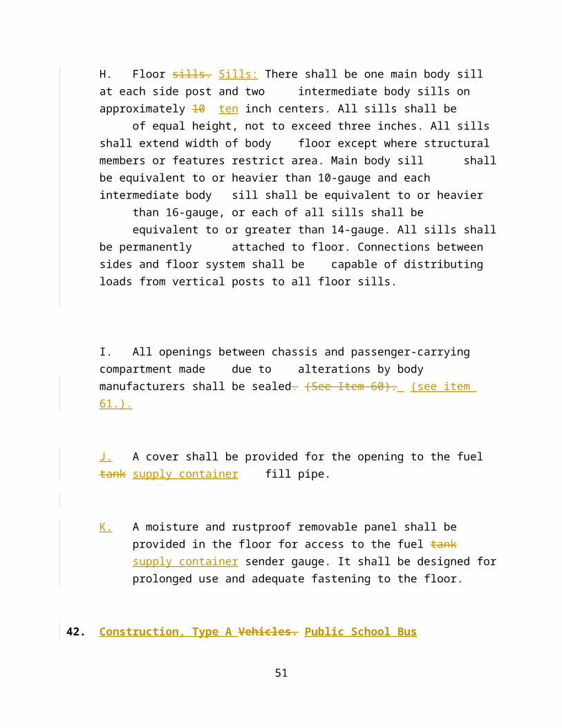
may shall not interfere with rear exit window and may not extend above the rear seating row.
5051. Hinges.
A. All exterior metal door hinges shall be designed to allow lubrication to be channeled to the center 75 percent of each hinge loop without disassembly, unless they are constructed of stainless steel, brass or non-metallic hinge pins or other designs that prevent corrosion.
5152. Identification of Public School Buses .
[A.] All lettering shall be of black paint or vinyl decal and conform to “Series B” for Standard Alphabets for Highway Signs. The words “SCHOOL BUS” shall be on reflective yellow background. See (see Diagrams 1 and 2. , pages 62-63). For purposes of identification, public school buses shall be lettered as follows:
1. Both the front and rear of the body shall bear the words, “SCHOOL BUS” in black letters eight inches in height.
2. The bus number shall be placed just back of the front warning sign on the left side, just behind the entrance door on the right side and be four inches high. The number is required on the left side of the front bumper (driver’s side). The number shall be placed on the rear body of the bus and shall be four inches high.
3. (Name of) County Public Schools or (Name of) City Public Schools shall be placed on each side of the public school bus body at the beltline and be four inches high.
4. Type of Fuel: Identification of fuel type shall be in 2 two inch lettering adjacent to the fuel filler opening.
5. A sign with black letters on clear or school bus yellow NSBY background, indicating the type of alternative fuel being used, may be placed on the side of the bus near the entrance door. No sign shall be more than 4-3/4 .75 inches long or more than 3-1/4 .25 inches high.
54
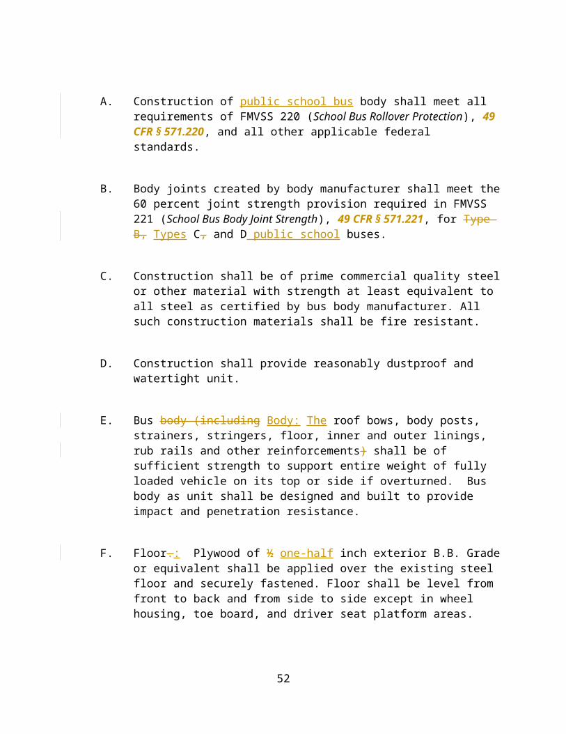
56. Options -: The following lettering and signs are options, but if equipped, they must shall conform to these specifications:
a. The bus number may shall be placed in the center of the public school bus roof with black (12-inch twelve inches minimum) numbers.
b. The bus number (four inches minimum) shall be placed on the inside rear header with black paint or vinyl decals. It shall not interfere with the Emergency Door letterings.
c. Battery -: The location of the battery identified by the word “Battery” or “Batteries” on the battery compartment door in 2 two inch lettering.
d. Traffic Warning Lights Sign: Shall be placed in between the top and bottom glass on the rear emergency door, and lettered “STOP WHEN RED LIGHTS FLASH.” The sign shall be marked with retro-reflective NSBY material comprising background for black letters, four inches in height. On a rear-engine Type D bus (RE) buses, the sign shall be placed in the center of the engine door. Exception: The sign shall not be mounted on any public MFSAB bus.
Exception: The sign shall not be mounted on any activity vehicle.
e. Stop for Railroad Crossing Sign: The sign shall be placed on the rear of the public school bus.
f. Identification Sign for Students: A sign with symbols and/or numbers displaying identification information for the students of the bus or route served shall be mounted on the right side of the
55
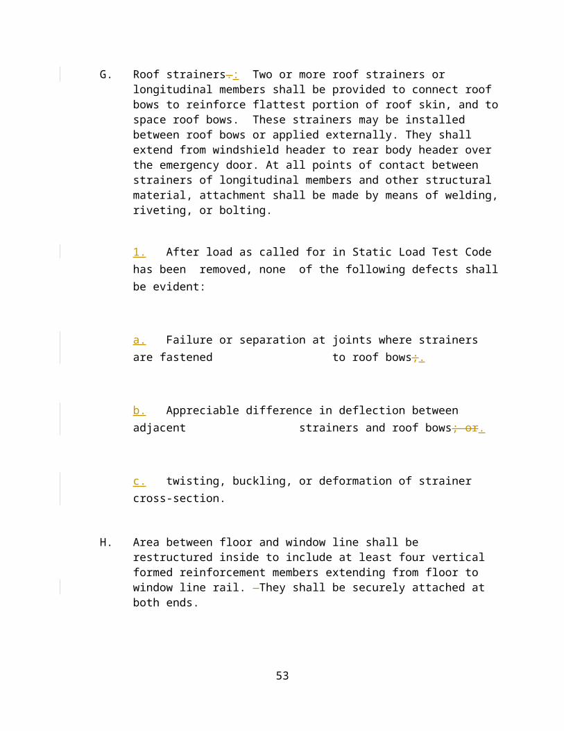
bus near the entrance door. The sign shall be no larger than 121 square inches.
g. American Flag Decals: Non-reflective, American Flag decals, no larger than 6 six inches by 10 ten inches shall be placed on the exterior of the bus, on both sides and/or at the rear of the bus. Types C and D public school buses. The decals shall be centered between the top two rub rails and mounted so that the right edge of the decal is no closer than 3 three inches from the bus number or so that the left edge of the decal is no further than 12 twelve inches from the bus number. A rear decal shall be centered in the rear of the bus.
Exception: Type A public school buses shall mount the American Flag decals below the second rub rail and centered below the bus number on both sides.
h. Bus Safety Hotline Sign: A sign with yellow lettering on black background may be mounted in the center of the rear bumper with the letters “School Bus Safety Hotline Call (area) xxx-xxxx.” The sign is not to exceed 3 ¼ .25 inches high x 10 ten inches wide.
67. Only manufacturer or dealer’s identification, logos, signs or other items approved by the Department of Education (DOE) VDOE may be displayed.
5253. Inside Height.
[A.] Inside body height shall be 72 inches or more, measured metal to metal, at any point on longitudinal center line from front vertical bow to rear vertical bow. Exception: Type A conversion van – Inside body height shall be 62 inches minimum. Does not apply to air conditioning equipment.
[B.] 53Type A public school buses inside body height shall be 62 inches minimum. Does not apply to air conditioning equipment.
56

54. Insulation.
A. Ceilings and walls shall be coated with proper materials to deaden sounds and to reduce vibrations to a minimum. Thermal insulation (minimum R-value of 5.5) shall be used to insulate walls and roof between inner and outer panels.
5455. Interior.
A. Interior of public school bus shall be free of all unnecessary projections likely to cause injury. This standard requires inner lining on ceilings and walls. Ceiling panels shall be constructed so as to contain lapped joints with all exposed edges hemmed to minimize sharpness. If lateral panels are used, forward panels shall be lapped by rear panels.
55.56. License Plates.
A. All vehicles public school buses shall be constructed so that mounting and securing of license plates will be compliant with FMVSS and the Code of Virginia,Section § 46.2-716.
56.57. Lights and Signals.
[A.] No lights or signals other than specified here shall be installed on public school buses, except those required by federal regulations. All lights and reflectors shall be approved by the Superintendent of the Virginia State Police VSP.
[1.] Clearance lights. Lights: Body shall be equipped with two red clearance lamps at rear, two amber clearance lamps at front, and intermediate side marker lamps on buses 30 feet or more in length controlled by headlight switch. They may be of armour type.
57
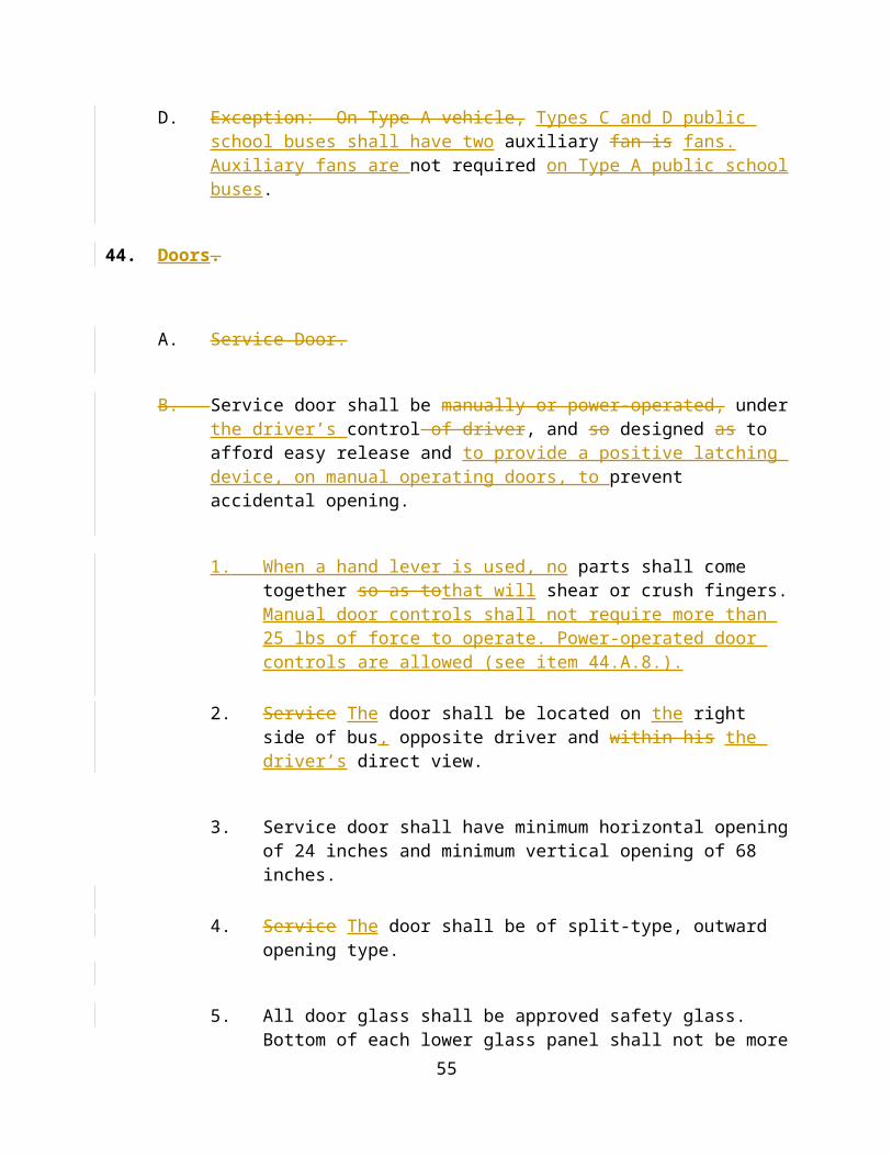
[2.] Identification lamps. Lamps: Three amber lamps shall be mounted on front and three red lamps on rear of body controlled by the headlight switch.
[3.] Stop and tail lamps. Bus Tail Lamps: Public school buses shall be equipped with two matched stop and tail lamps of heavy duty type, which shall be in combination, emitting red light plainly visible from a distance of at least 500 feet to rear, and mounted on rear end with their centers not less than 12 nor more than 24 inches from plane side of body, and not less than six or more than 18 inches below D-glass in rear of body. They shall be approximately seven inches in diameter or, if a shape other than round, a minimum 38 square inches of illuminated area and shall meet SAE specifications. These lights shall be on the same horizontal line with the turn signal units and shall not flash.
[4.] Back-up lamps. Lamps: The public school bus body shall be equipped with 2 two white rear back-up lamps that are at least four inches in diameter or, if a shape other than round, a minimum of 12 twelve square inches of illuminated area and shall meet FMVSS 108 (Lamps, Reflective Devices, and Associated Equipment). If back-up lamps are placed on the same horizontal line as the brake lamps and turn signal lamps, they shall be to the inside.
[5.] Interior lamps. Lamps: Interior lamps shall be provided which adequately illuminate aisles and step well.
[6.] Turn signal units. Bus Signal Units: Public school buses shall be equipped with Class A, flashing turn signal units of heavy-duty type. These signals shall be independent units equipped with amber lenses on all faces. The turn signals/directional signal units shall activate only when ignition is in “on ON” position. A pilot light or lights(s) shall indicate when these lights are activated. The front lights shall be mounted near the front corners of chassis on each side. The rear lights shall be seven inches in diameter, or if a shape other than round, the lights must be 38 square inches in area and mounted not less than six nor more than 18 inches from plane of the side of the body and not less than six nor more than 18 inches below D-glass in rear of body. They shall be on the same horizontal line with the stop and tail lights required in item 3 above.
[a.] In addition to the turn signals described above, two amber lenses metal turn signal lamps of armour-type with a minimum of four candlepower each shall be mounted on the body side at approximate seat level height and located just to the rear of the
58

entrance door on the right side of the body and approximately the same location on the left side. They are to be connected to and function with the regular turn signal lamps. Such lamps shall provide 180o 180 degrees angle vision and if painted, they shall be black.
[b.] Exception: Type A public school bus: Turn signals shall be chassis manufacturer’s standard.
[7.] Hazard warning signal. Warning Signal: The turn signal units shall also function as the hazard warning system. The system shall operate independently of the ignition switch and, when energized, shall cause all turn signal lamps to flash simultaneously.
[8.] Reflex reflectors. Reflectors: (Class A) Two amber lights and two amber reflectors (they may be combined) shall be mounted, one on each side, near the front of the chassis. Two three 3-inch red reflectors shall be mounted,; one on each side near the rear of the body and two three 3-inch red reflectors shall be mounted on the rear above the bumper. Two intermediate amber three-inch reflectors, one on each side near the middle of the bus, shall be mounted on buses 30 feet or more in length. They shall be mounted in accordance with FMVSS 108 (Lamps, Reflective Devices, and Associated Equipment).
[9.] School bus traffic warning lights.
[10.] School Bus Traffic Warning Lights: Public school buses shall be equipped with four red lights and four amber lights. One amber light shall be located near each red light, at the same level, but closer to the vertical centerline of the bus. All lights shall comply with SAE standards for school bus warning lamps.
a. A non-sequential system for the traffic warning lights shall be installed that allow the red traffic warning lights to activate when the door opens. When doors close all lights shall immediately deactivate.
[b.] The traffic warning light system shall be wired so that the amber lights are activated manually by a hand operated switch. When There shall be a momentary Amber Light Cancel Switch to deactivate the amber warning lights if the driver has determined a stop is not needed and the door does not need to be opened. When the door is
59
opened, amber lights will automatically deactivate and red traffic warning lights, warning sign with flashing lights and crossing control arm shall be activated. When the door is closed, red traffic warning lights, warning sign with flashing lights and traffic crossing control arm shall be deactivated.
dc. Warning Light Cancel Switch for Railroads: There shall be a momentary warning light cancel switch labeled “R/R Cancel” that when depressed and released deactivates the red traffic warning lights, crossing arm and stop arm for one entrance door cycle. The Warning Light Cancel Switch for Railroads shall be mounted on the accessory console, orange in color, clearly distinguishable, visible and accessible to the driver. The driver need not depress or reactivate any switch in any way for the continued operation of the non-sequential system.
d. There shall also be a separate master warning light control switch Master Warning Light Control Switch that would allow for deactivation of this feature during maintenance operation. The master light control circuit shall be connected to the cold side or switched side of the ignition switch and mounted on the accessory console, clearly labeled, distinguishable, red in color, or be black in color with a red bezel ring. This switch shall be located on the switch panel at the furthest point away from other light controls and door operations switches.
fe. The flasher and the relay shall be fastened in a compartment in the driver area and be easily accessible for servicing. The location of the flasher shall be approved by the Department of Education VDOE.
gf. System shall contain an amber pilot light for amber lamps and a red pilot light for red lamps, clearly visible to the driver, to indicate when system is activated.
60
hg. A black border 1 ¼ .25 to 3 inches wide shall be painted around the warning lights and must be equipped with a black painted hooded housing.
ih. All electrical connections shall be soldered or connected by an acceptable SAE method.
ji. All switches and pilot lights shall be properly identified by labels.
kj. There shall be an interrupt feature in the system to interrupt the traffic warning sign and the crossing control arm when their use is not desired. This feature shall consist of a double throw relay and a momentary switch.
lk. Amber start switch Start Switch, Amber Cancel Switch, Warning Light Cancel Switch for Railroads “R/R Cancel,” traffic warning sign/crossing control Traffic Warning Sign/Crossing Control arm, master warning light control switch Master Warning Light Control Switch and interrupt switch Interrupt Switch shall be momentary switches.
ml. There shall be no controls and/or switches located in the steering wheel for operation of any system except controls and/or switches of the horn or optional cruise control. All controls and/or switches shall be labeled according to their function and shall meet the standards of FMVSS 101 (Controls and Displays).
NOTE: Cruise control option is for activity buses only.
m. Additional front, rear, and side-mounting warning lights for school divisions approved for participation in the Board of Education’s BOE approved pilot program. Additional warning lights may be mounted on the front hood, bottom rear of the school bus above the
61
bumper, and front sides of the school bus above the entrance door and the driver’s window. Lights shall work in conjunction with the standard warning light system and shall meet FMVSS and SAE standards or must be of a type approved by the Virginia State Police. VSP. Contact the VDOE for approved mounting locations and lighting systems.
Optional Equipment.
n. Fog lights Must (optional) shall be mounted by the manufacturer, meet FMVSS requirements and comply with the Code of Virginia Code..
10. School bus Bus Traffic Warning Sign: Public school buses shall be equipped with a traffic warning sign must conform conforming to FMVSS 131 (School Bus Pedestrian Safety Devices).
a. Warning sign shall be mounted on the left side near the front of the bus immediately below the window line.
b. Sign shall be of the octagon series, 18 inches in diameter, and be equipped with wind guard. The sign shall have a red background with a ½ one-half inch white border, and the word “STOP” on both sides in white letters, six inches high and one inch wide. The sign shall be reflective.
c. Sign shall have double-faced alternately flashing red lights, four inches in diameter, located at the top and bottom most portions of the sign, one above the other.
d. The sign shall be connected and energized through the red traffic warning lamps.
62
e. Air operated signs require air pressure regulator in addition to control valve. Source of supply shall be the main air tank with a pressure protection valve at the tank.
f. Sign and components shall comply with all provisions of SAEJ 1133.
g. A second school bus traffic warning sign on the left side near the rear of the bus, may be mounted on all 65, or larger sized passenger Type Types C and D public school buses.
11. School Bus Crossing Control Arm.: Public school buses shall be equipped with a crossing control arm mounted on the right side of the front bumper.
a. When opened, the arm shall extend in a line parallel to the body side and aligned with the right front wheel.
b. Appropriate grommets or a loom shall be used where wires or tubes go through holes in bumper and firewall.
b. School buses shall be equipped with a crossing control arm mounted on the right side of the front bumper. When opened, this arm shall extend in a line parallel to the body side and aligned with the right front wheel.
c. All components of the crossing control arm and all connections shall be weatherproofed.
d. The crossing control arm shall incorporate system connectors (electrical, vacuum or air) at the gate and shall be easily removable to allow for towing of the bus. Source of supply for
63
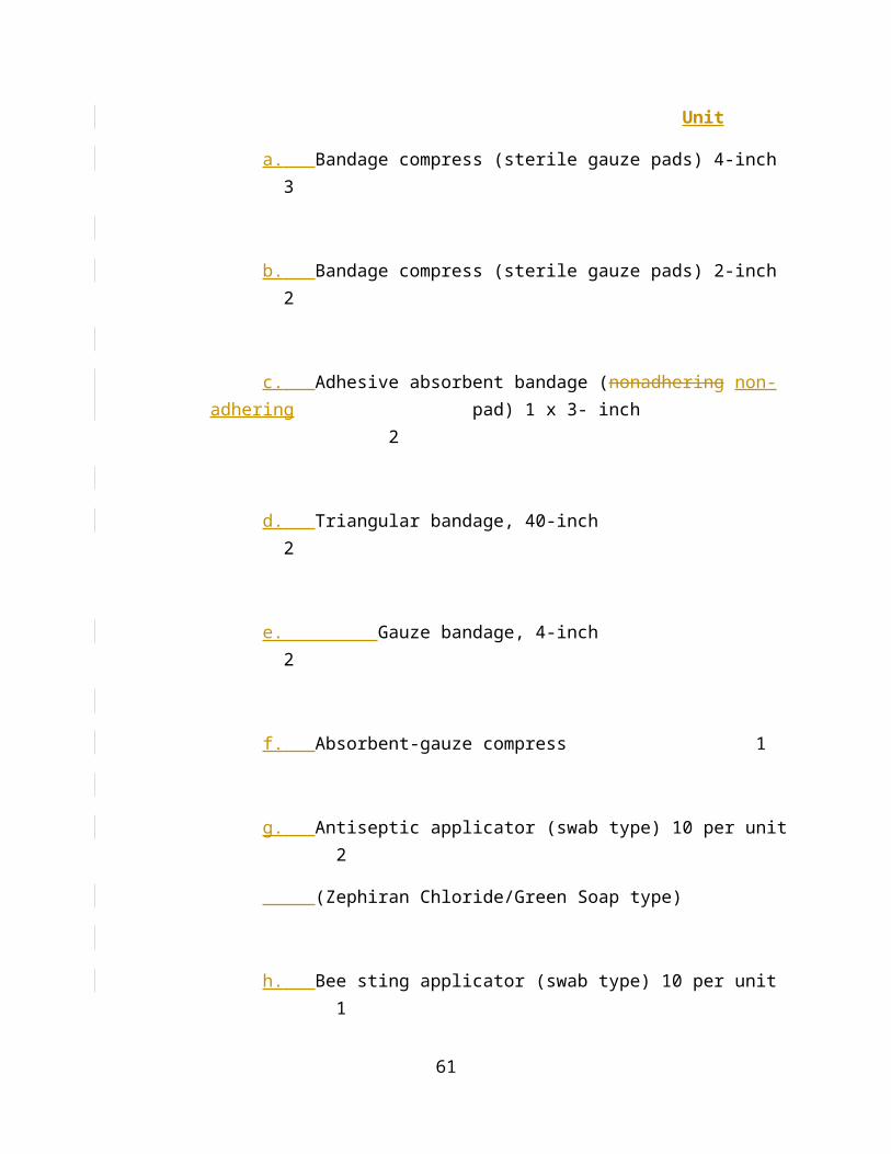
air-operated arms shall be the main air supply tank with pressure protection valve at tank.
e. The crossing control arm shall be constructed of non-corrodible or nonferrous material.
f. There shall be no sharp edges or projections that could cause injury or be a hazard to students. The end of the arm shall be rounded.
g. The crossing control arm shall extend a minimum of 70 inches (measured from the bumper at the arm assembly attachment point) when in the extended position. The crossing control arm shall not extend past the end of the bumper when in the stowed position.
h. The crossing control arm shall extend simultaneously with the traffic warning sign(s) and shall be connected and energized through the traffic warning lamps.
i. The assembly shall include a device attached to the bumper near the end of the arm to automatically retain the arm while in the stowed position. That device shall not interfere with normal operations of the crossing control arm.
12. Strobe Warning Light.
a. Each public school bus shall be equipped with a white flashing strobe light meeting the following requirements:.
b. The strobe light shall have self-contained power supply.
64

c. The strobe light base shall be LexanTM (or approved equal) or other polycarbonate or corrosion resistant metallic material. Lens The lamp shall be have a single clear LexanTM or other polycarbonate material or equal or better strength, resilience, and durability. lens emitting light 360 ° around its vertical axis, meeting the requirements of SAE J845. Unit shall be sealed to protect against intrusion of dust and moisture. All external fasteners including mounting screws shall be stainless steel. Unit shall have mounting gasket to isolate the light assembly from vibration.
3. Electrical characteristics: Shall have a flash energy of minimum 8 joules. Shall have 80 (plus or minus 10) single or double flashes per minute. Shall have integral fuse or circuit breaker protection and reverse polarity protection. Maximum current draw shall be 2 amperes at 12 volts.
4. Dimensions and location: Overall
d. The overall height of the unit shall be approximately four inches to 6 six inches, with lens diameter approximately four inches to 6 six inches. Mounting location is to be centered (laterally) on roof of bus, approximately 48 inches (longitudinally) from rear edge of rear roof cap. and shall meet SAE J845 specifications Shall meet SAE J575..
6. Body
e. The body circuitry :Shall shall include a separate, clearly labeled driver’s panel mounted switch, with a clearly labeled pilot light.
5758. Metal Treatment.
65
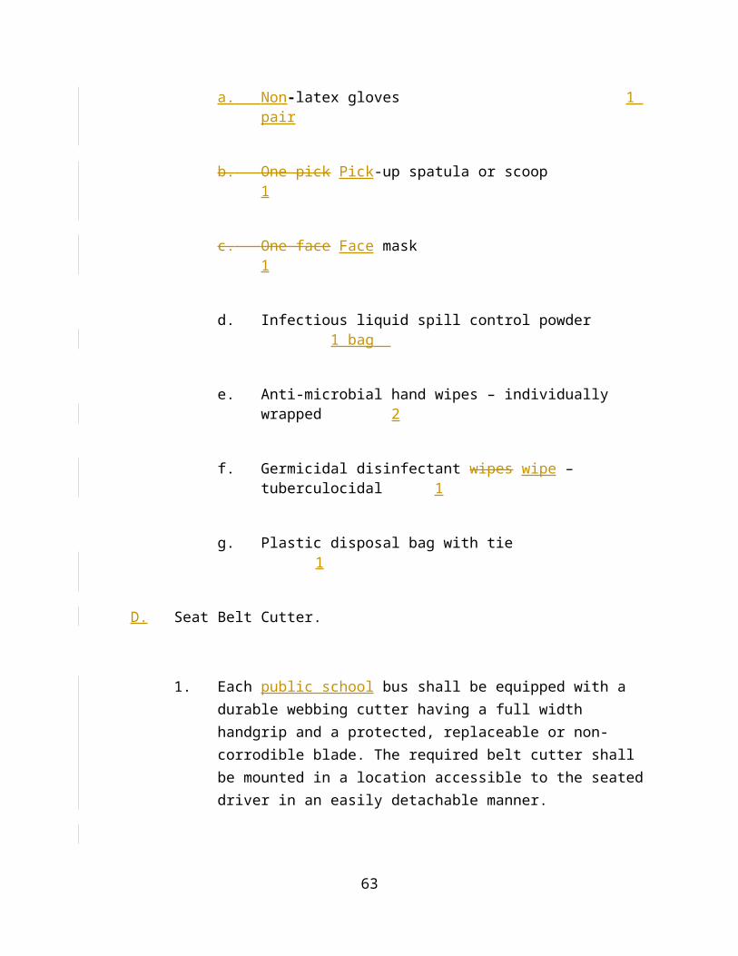
[A.] All metal parts that will be painted shall be chemically cleaned, etched, zinc-phosphate-coated, and zinc-chromate or epoxy-primed or conditioned by equivalent process.
58
59. Mirrors.
[A.] Types C and D public school bus interior rear-view mirror mirrors shall be at least 6 x 30 inches, metal encased safety glass of at least 1/8 inch with a minimum thickness of .125 inch, which will afford good view of pupils and roadway to rear and shall be installed in such a way that vibration will be reduced to a minimum. It shall have rounded corners and protected edges.
[B.] Exception: Type A - Interior public school bus interior rear-view mirror to shall be 6 x 16 inches.
A.[C.] All public school buses shall have a mirror system that conforms to FMVSS 111 (Rearview Mirrors), 49 CFR § 271.111 as amended.
B.[D.] Thermostatically controlled heated exterior mirrors are permissible.
C.[E.] Motorized exterior mirrors may be used.
5960. Mounting.
[A.] Chassis frame shall extend to rear edge of rear body cross member. Bus body shall be attached to chassis frame in such manner as to prevent shifting or separation of body from chassis under severe operating conditions.
66
A.[B.] Body front shall be attached and sealed to chassis cowl in such manner as to prevent entry of water, dust, and fumes through joint between chassis cowl and body.
[C.] Insulating material shall be placed at all contact points between body and chassis frame on Types A, B, C, and D public school buses. Insulating material shall be approximately ¼ .125 inch thick and shall be so attached to chassis frame or body member that it will not move under severe operating conditions.
6061. Openings.
[A.] Any openings in body or front fenders of chassis resulting from change necessary to furnish required components shall be sealed. (See Item (see items 23., 41.I., and Item 41 i and Item 42 j.).J.).
61. Overall
62. Overall Length .
A. Overall length of public school bus shall not exceed 40 feet when measured from bumper to bumper.
62 63. Width.
[A.] Overall width of public school bus shall not exceed 100 inches, including traffic-warning sign in closed position. Outside rearview mirrors are excluded.
63.64. Rub Rails.
A. There shall be one rub rail located on each side of the public school bus at seat cushion level which extends from the rear side of the entrance door completely around the bus body (except the emergency door or any maintenance access door) to the point of curvature near the outside cowl on the left side, or to the front corner of the bus body.
67
[B.] There shall be one additional rub rail located on each side at, or no more than 10 ten inches above, the floor line. The rub rail shall cover the same longitudinal area as the upper rub rail, except at the wheel housings, and it shall extend only to the radii of the right and left rear corners.
B.[C.] Both rub rails shall be attached at each body post and at all other upright structural members.
C.[D.] Each rub rail shall be four inches or more in width in their finished form, shall be constructed of 16-gauge steel or suitable material of equivalent strength and shall be constructed in corrugated or ribbed fashion.
[E.] Both rub rails shall be applied outside the body or outside body posts. (Pressed-in or snap-on rub rails do not satisfy this requirement.) For Type A-1 public school buses using the body provided by the chassis manufacturer or for types A-2, B, C, and D public school buses using the rear engine compartment, rub rails need not extend around the rear corners.
D.[F.] There shall be a rub rail or equivalent bracing located horizontally at the bottom edge of the body side skirts.
6465. Seat Belt for Driver.
[A.] A locking retractor type Type 2-lap belt/shoulder harness seat belt shall be provided for the driver. Each belt section shall be booted so as to keep the buckle and button-type latch off the floor and within easy reach of the driver. Belt shall be anchored in such a manner or guided at the seat frame so as to prevent the driver from sliding sideways from under the belt. The driver’s seat belt shall be high visible orange in color on all public school buses. The driver’s seat belt shall be high visible orange in color on all buses. Exception: Type A buses may have driver seat belts high visible orange in color.
65. Seats.
68
66. Seating
A. Passenger Seating.
1. Public school bus design capacities shall be in accordance with 49 CFR, Part 571.3, Definitions, and FMVSS 222 (School Bus Passenger Seating and Crash Protection).
2. All seats shall have a minimum cushion depth of 15 inches. Indeterminingseating capacity, a seat back height of bus, allowable
averagerump width shall be 13 inches. (See Item 36.) 24inches above the seating reference point, and must comply with all
other requirements of FMVSS 222.
3. All restraining barriers and passenger seats shall be constructed with materials that enable them to meet the criteria of the School Bus Seat Upholstery Fire Block Test and comply with FMVSS 302 (Flammability of Interior Materials), 49 CFR Part 571.302.
4. Each seat leg shall be secured to the floor by bolts, washers and nuts in order to meet the performance requirements of FMVSS
222. Flange-head nuts may be used in lieu of nuts and washers. All seat frames attached to the seat rail shall be fastened with two or more bolts, washers and nuts, or with flange-head nuts. Seats may be track-mounted in conformance with FMVSS 222.
5. If track seating is installed, the manufacturer shall supply minimum and maximum seat spacing dimensions (applicable to
the bus) which conform to FMVSS 222. This information shall be on a label permanently affixed to the bus.
69
6. Seating plans for public schools buses with wheelchair positions: (see Item 92A. item 92.A.). All public school bus seating shall be of a three-to-three arrangement with the exception of the last row seat to the left of any rear emergency door. This seat shall meet the standards set forth in FMVSS 222 for last row seating and ingress and egress of standards of FMVSS 217 for emergency door and aisle clearance at that position. There shall be provided a full width barrier in front of each seating position. Type D, rear engine (RE) public school buses shall be exempt from the last row requirements. Type A public school buses with a capacity of 16 passengers or less may have two-to-two seating arrangement with 30 inch seats.
Exception – Type A – 16 passenger may have two-to-two seating arrangement, with 30 inch seats.
D. Floor track seat securement may be used and the manufacturer shall supply minimum and maximum seat spacing dimensions (applicable to the bus) which comply with FMVSS No 222. This information shall be on a label permanently affixed to the bus.
E. Passenger seat cushion retention system shall meet FMVSS 222.
F. 7. All public school buses shall be equipped with jump seats or portable seats. restraining barriers which conform to FMVSS 222.
G. Seat spacing shall meet FMVSS 222 (School Bus Passenger Seating and Crash Protection).
H. Seat and back cushions of all seats shall be designed to safely support designated number of passengers under normal road conditions encountered in school bus service. Covering of seat cushions shall be of material having 42 ounce finished weight, 54-inch width, and finished vinyl coating of 1.06 broken twill. Material on polyester drill and polyester cotton twill knit backing with equal vinyl coating
70
which meets or exceeds the laboratory test results for the 42 ounce 1.06 covering may be used. Padding and seat covers on all seats shall comply with provisions of FMVSS 302 (Flammability of Interior Materials), 49 CFR § 571.302.
I. Minimum distance between steering wheel and backrest of driver’s seat shall be 11 inches.
8. A flip-up seat may be installed at any side emergency door. If provided, the flip-up seat shall conform to FMVSS 222 and aisle clearance requirements of FMVSS 217 (Bus Emergency Exits and Window Retention and Release). The flip-up seat shall be free of sharp projections on the underside of the seat bottom. The underside of the flip-up seat bottoms shall be padded or contoured to reduce the possibility of clothing being snagged. Flip-up seats shall be constructed to prevent passenger limbs from becoming entrapped between the seat back and the seat cushion when the seat is in the upright position. The seat cushion shall be designed to rise to a vertical position automatically when it is not occupied.
9. Lap belts shall not be installed on passenger seats in large school buses (over 10,000 pounds GVWR) except in conjunction with child safety restraint systems that comply with the requirements of FMVSS 213 (Child Restraint Systems).
B. Pre-School Age Seating.
1. Passenger seats designed to accommodate a child or infant carrier seat shall comply with FMVSS 225 (Child Restraint Anchorage Systems). These seats shall be in compliance with NHTSA’s “Guideline for the Safe Transportation of Pre-school Age Children in School Buses” (see item 66.A.9.).
C. Driver Seat.
71

1. The driver’s seat supplied by the body manufacturer shall be a high back seat. The seat back shall be adjustable to 15 degrees minimum, without requiring the use of tools. The seat shall be equipped with a head restraint to accommodate a 5th percentile female to a 95th percentile adult male, as defined in FMVSS No. 208, (Occupant Crash Protection.).
2. Minimum distance between steering wheel and backrest of driver’s seat shall be 11 inches.
3. Type A public school buses may utilize the standard driver’s seat provided by the chassis manufacturer.
J. Minimum of 36-inch headroom for sitting position above top of undepressed cushion line of all seats shall be provided. Measurement shall be made vertically not more than seven inches from sidewall at cushion height and at fore-and-aft center of cushion.
K. Backs of all seats of similar size shall be of same width at top and of same height from floor and shall slant at same angle with floor.
L. Seat back heights shall be between 24 and 27 inches measured from seating reference point.
Exception: Seats with optional child safety restraining systems shall comply with FMVSS 222 (School Bus Passenger Seating and Crash Protection).
6667. Barrier.
72
A. A padded barrier shall be installed at rear of driver’s seat in such a position as not to interfere with adjustment of driver’s seat.
B. A padded barrier shall be installed at rear of entrance step well. Barrier to coincide with length of the right front seat cushion with minimum width of 26 inches and shall have a modesty panel to extend from bottom of barrier to floor.
[C.] All restraining barriers and passenger seats shall be constructed with materials that enable them to meet the criteria of the School Bus Seat Upholstery Fire Block Test. Padding and veering shall comply with provisions of FMVSS 302 (Flammability of Interior Materials), 49 CFR §Part 571.302.
6768. Steps.
A. First step at service entrance door shall be not less than 10 inches and not more than 16 inches from the ground, based on standard chassis specifications.
B. Service Entrance door entrance may be equipped with two-step or three-step step well. Risers in each case shall be approximately equal.
C. Steps shall be enclosed to prevent accumulation of ice and snow.
B.[D.] Steps shall not protrude beyond side bodyline.
C.[E.] Grab handle not less than 20 inches in length shall be provided in unobstructed location inside doorway, but shall not be attached so that it will interfere with the opening of the glove compartment door. This handle shall be designed to eliminate exposed ends that would catch passenger clothing and shall be so placed in a position to aid small children entering the bus.
F. Step covering: All steps, including the floor line platform area, shall be covered with an elastomer floor covering having a minimum overall thickness of 0.187 inch.
73
1. The step covering shall be permanently bonded to a durable backing material that is resistant to corrosion.
2. Steps, including the floor line platform area, shall have a 1 ½ .5 inch nosing that contrasts in color by at least 70 percent measured in accordance with the contrasting color specification in 36 CFR, Part 1192, ADA, (Accessibility Guidelines for Transportation Vehicles.).
3. Step treads shall have the following characteristics:
a. Abrasion resistance: Step tread material weight loss shall not exceed 0.40 percent, as tested under ASTM D-4060, Standard Test Method for Abrasion Resistance of Organic Coatings by the Taber Abraser, (CS-17 Wheel, 1,000 gram, 1,000 cycle)).
b. Weathering resistance: Step treads shall not break, crack, or check after ozone exposure (7 days at 50 phm at 40 degrees ° C) and Weatherometer exposure (ASTEM D-750, Standard Test method for Rubber Deterioration in Carbon-Arc Weathering Apparatus, 7 days)).
c. Flame resistance: Step treads shall have a calculated burn rate of .01 or less using the test methods, procedures and formulas listed in FMVSS No. 302 (Flammability of Interior Materials).
G. There shall be a “no-smoking No Smoking” sign placed on the top step riser of the entrance step well. The letters shall be red in color with a white background and a length of 9 ½ .5 inches and lettering height of 1 ¼ .125 inches.
6869. Stirrup Steps.
74
A. If the windshield and lamps are not easily accessible from the ground, there may be at least 1 one folding stirrup step or recessed foothold installed on each side of the front of the body for easy accessibility for cleaning. There also may be a grab handle installed in conjunction with the step. Steps are permitted in or on the front bumper in lieu of the stirrup steps if the windshield and lamps are easily accessible for cleaning from that position.
6970. Storage and Luggage Compartments.
[A.] Vehicles Public school buses may be equipped with luggage compartments or tool compartments in the body skirt provided they do not reduce ground clearance to less than 14 ½ .5 inches from bottom of compartment and that the addition of the compartments does not exceed the vehicles’ GVWR.
[B.] Optional: Drivers A driver’s storage compartment may be above the driver’s area and must not impede ingress and egress. It shall not violate any federal safety FMVSS standard or the Code of Virginia.
70
71. Sun Shield.
A. Interior adjustable transparent sun shield, darkest shade available, not less than 6 x 30 inches shall be installed in position convenient for use by driver.
[B.] Exception: Type A vehicles public school buses – Manufacturer’s standard is acceptable.
7172. Trash Container and Hold Device (Optional).)
A. When requested or used, the The trash container shall be secured by a holding device that is designed to prevent movement and to allow easy removal and
75
replacement. It shall be soft, pliable, and installed in an accessible location in the driver’s compartment, not obstructing passenger access to the entrance door.
7273. Undercoating.
[A.] Entire underside of public school bus body, including floor sections, cross members, and below floor line side panels, shall be coated with rust-proofing compound for which compound manufacturer has issued notarized certification of compliance to bus body building that compounds meet or exceed all performance requirements of SAE J1959.
A.[B.] Undercoating compound shall be applied with suitable airless or conventional spray equipment to the undercoating manufacturer recommended film thickness and shall show no evidence of voids in cured film. Undercoating is expected to prevent rust under all bus service conditions for minimum of five years.
B.[C.] The undercoating material shall not cover any exhaust components of the chassis.
7374. Ventilation.
A. Body shall be equipped with suitable, controlled ventilating system of sufficient capacity to maintain proper quantity of air under operating conditions without opening of windows except in extremely warm weather.
B. Static-type, non-closable, exhaust roof ventilators shall be installed in low-pressure area of roof panel.
C. Auxiliary fans shall meet the following requirements:
1. Types C and D public school buses shall be equipped with two fans. Type A public school buses may be equipped with auxiliary fans but is not required. Fans for left and right sides of the windshield shall be placed in a location where they can be adjusted for maximum effectiveness and where they do not obstruct vision to any mirror. Note: Type A buses may be equipped with one fan.
76

2. Fans shall have 6 a six-inch (nominal) diameter; and be 3.Fan blades shall be enclosed in a protective cage.
3. Each fan shall be controlled by a separate switch.
7475. Water Test.
[A.] Each and every public school bus body, after it is mounted on chassis ready for delivery, shall be subjected to a thorough water test in which water under pressure equal to a driving rain is forced against the entire bus body from various directions. Any leaks detected are to be repaired before the bus is declared ready for delivery.
7576. Wheel Housings.
A. Wheel housings shall be of full open type.
B. Wheel housings shall be designed to support seat and passenger loads and shall be attached to floor sheets in such manner as to prevent any dust or water from entering the body. Wheel housings shall be constructed of 16-gauge (or thicker) steel.
C. Inside height of wheel housings above floor line shall not exceed 12 inches.
D. No part of a raised wheel housing shall extend into the emergency door opening.
E. Wheel housings shall provide clearance for dual wheels as established by National Association of Chain Manufacturers. Mounting of housings in the wheel area must be free of protruding screws and bolts.
77
[F.] Exception: Type A vehicles Standard does not apply to conversion vans.
7677. Windshield and Windows.
[A.] All glass in windshield, windows, and doors shall be of approved safety glass, so mounted so that permanent mark is visible, and of sufficient quality to prevent distortion of view in any direction. Windshield shall be AS1 and all other glass shall be AS2.
A.[B.] Plastic glazing material of a thickness comparable to AS2 glass, meeting ANSI Standard Z 26.1 and FMVSS 205 (Glazing Materials), 49 CFR § 571.205, may be used in side windows behind the driver’s compartment.
B.[C.] Windshield shall have horizontal shade band consistent with SAE J-100 and Code of Virginia.
C.[D.] Each full side window shall provide unobstructed emergency opening at least nine inches high and 22 inches wide, obtained either by lowering of window or by use of knock-out type split-sash windows.
D. Approved tinted glass or plastic glazing material may be used consistent with the Code of Virginia.
E. Windshield shall comply with all federal and state regulations.
77
78. Windshield Washers.
[A.] Windshield washers meeting federal requirements shall be provided and shall be controlled by a switch accessible to the driver. Reservoir shall be mounted outside passenger compartment.
7879. Windshield Wipers.
78
A. Bus shall be equipped with variable-speed windshield wipers of air or electric-type powered by a motor or motors of sufficient power to operate wipers.
B. Blades and arms shall be of such size that minimum blade length will be 12 inches with longer blades being used whenever possible.
C. The wipers shall meet the requirements of FMVSS 104 (Windshield Wiping and Washing Systems).
7980. Wiring.
[A.] All wiring shall conform to current standards of Society of Automotive Engineers SAE.
A.[B.] Circuits
1. Wiring shall be arranged in at least 12 regular circuits as follows:
a. Head, tail, stop (brake) and instrument panel lamps.
b. Clearance lamps.
c. Dome and step well lamps.
d. Starter motor.
e. Ignition.
f. Turn-signal units.
g. Alternately flashing red signal lamps.
79
h. Horns.
i. Heater and defroster.
j. Emergency door buzzer.
[j.] Auxiliary fan fans.
[k.] Booster pump (Type A bus exempt)).
2. Any of the above combination circuits may be subdivided into additional independent circuits.
3. Whenever possible, all other electrical functions (such as electric-type windshield wipers) shall be provided with independent and properly protected circuits.
4. Each body circuit shall be color coded or numbered and a diagram of the circuits shall be attached to the body in a readily accessible location.
B.[C.] A circuit breaker shall be provided for each circuit except starter motor and ignition circuits.
C.[D.] A continuous duty solenoid relay operated by the ignition switch, for Circuits i, j, k, and l.
[E.] All wires within the public school bus body shall be insulated and protected by covering of fibrous loom (or equivalent) that will protect them from external damage and minimize dangers from short circuits. Whenever wires pass through a body member, additional protection in a form of appropriate type of insert shall be provided.
D.[F.] All light circuits shall be such as to provide, as nearly as possible, bulb design voltage at light bulb terminals.
80
G. Buses using multiplexed electrical systems may meet the intent of these specifications the Specifications without the use of specified equipment, subject to the approval of the Department of Education VDOE.
H. There shall be a manual noise suppression switch installed in the control panel. The switch shall be labeled and alternately colored. This switch shall be an on/off type that deactivates body equipment that produces noise, including, at least, the AM/FM radio, CD player, heaters, air conditioners, fans, and defrosters. This switch shall not deactivate safety systems, such as windshield wipers or lighting systems.
SPECIFICATIONS FOR ACTIVITY BUSES PUBLIC SCHOOL MFSAB
[80.] Activity Buses.81. Public School MFSAB
A. Activity Public school MFSAB buses shall meet all Federal Motor Vehicle Safety Standards FMVSS requirements for public school buses except as noted in Items 80 this section (see items 81.B. through 80.F.81.G.).
(NOTE: Any variation
B. Variations from the specifications Specifications, in the form of additional equipment or changes in style of equipment, without prior approval of from the DOE, is VDOE, are prohibited.).
BC. Identification.
81
[1.] The activity public school MFSAB bus body shall be identified “Activity Bus”, lettered 8 eight inches in height in the front and rear of the vehicle.
2. The name of the school division or individual school shall be lettered in at least 4 inch four inches height in the beltline area.
3. All lettering and numbering shall be painted or be vinyl decals of a contrasting color of the body and conform to FMVSS and Virginia School Bus, the Specifications, and shall meet all reflectivity standards.
4. No manufacturer or vendor logos, signs or other items not approved in the Virginia School Bus Specifications shall be displayed.
D. Color.
1. The activity public school MFSAB bus shall not be painted NSBY. The local school division may determine the color of the body of the vehicle bus and the color scheme may utilize up to 2 two colors. This combination may be in addition to a white painted roof. It is recommended that light colors be used for the body color to enhance visibility by other vehicles. Markings shall be contrasted against selected colors for ease of identification during periods of reduced visibility other than darkness. NOTE: The NSBY color shall not be used as a part of any color scheme.
E. Lights and Warning Devices.
1. All activity public school MFSAB buses shall meet all state and FMVSS for public school bus lighting and warning device requirements with the following exceptions:
82
a. The 8 Public school MFSAB buses shall not be equipped with the eight-lamp, traffic warning light system shall not be equipped.
b. The Public school MFSAB buses shall not be equipped with any flashing lighted stop arm or and the crossing control arm shall not be equipped.
F. Seats.
1. Other types of seats and increased spacing, which meet all regulations of FMVSS 222 (School Bus Passenger Seating and Crash Protection) and 302 (Flammability of Interior Materials) may be used in lieu of regular public school bus seats.
G. Cruise Control.
1. May only be installed on activity public school MFSAB buses and operated in accordance with regulation speeds.
NOTE: Not permitted to
2. Shall not be installed on yellow school buses.
SPECIFICATIONS FOR PUBLIC SCHOOL
WHEELCHAIR LIFT BUSES
8182. General Requirements.
83
[A.] School Public school buses or school vehicles designed for transporting children with special transportation needs shall comply with Virginia’s standards applicable to school buses and Federal Motor Vehicle Safety Standards FMVSS as applicable to their GVWR category.
[B.] Any public school bus that is used for the transportation of children, who are confined to a wheelchair or other restraining devices that prohibit use of the regular service entrance, shall be equipped with a power lift,. unless a ramp is needed for unusual circumstances.
A.[C.] Lift shall be located on the right side of the body, in no way attached to the exterior sides of the bus but confined within the perimeter of the school bus body when not extended.
8283. Aisles.
A. All aisles leading to the emergency door from wheelchair area shall be a minimum of 30 inches in width. A wheelchair securement position shall never be located directly in front of (blocking) a power lift door location.
83.84. Communications.
[A.] Special education public school buses shall be equipped with a two-way communication system. (See Item (see item 40.A.).).
84.85. Fastening Devices.
A. Unless otherwise specified below, fastening devices shall conform to FMVSS 222 (School Bus Passenger Seating and Crash Protection), 49 CFR § 571.222, as amended.
[1.] Wheelchair fastening devices shall be provided and attached to the floor or walls or both to enable securement of wheelchairs in the vehicle. public school bus. The devices shall be of the type that requires human intervention to unlatch or disengage. The fastening devices shall be
84
designed to withstand forces up to 3,000 pounds lbs. per tie-down leg or clamping mechanism or 12,000 pounds lbs. total for each wheelchair.
1.[2.] Additional fastening devices may be needed to assist the student due to the many different configurations of chairs and exceptionalities.
8586. Heaters.
[A.] An additional heater shall be installed in the rear portion of the bus behind wheel wells as required in Item 48 I, except a 50,000 minimum BTU heater may be used in bodies originally designed for 31-66 passenger capacity and 34 30,000 minimum BTU heaters may be used in bodies of 30 passengers or less. Hose to rear heater, when under body shall be encased in metal tube.
8687. Identification.
[A.] Buses Public school buses with wheelchair lifts used for transporting children with physical disabilities shall display the universal handicapped International Symbol of Accessibility symbols located on the front and rear of the vehicle bus below the window line. Such emblems shall be white on blue, shall be a minimum of nine inches and a maximum of 12 inches in size, and shall be of a high-intensity retro reflective material meeting the requirements of Federal Highway Administration (FHWA) FP-85, Standard Specifications for Construction of Roads and Bridges on Federal Highway Projects. They shall be placed so as not to cover lettering, lamps or glass.
8788. Passenger Capacity Rating.
A. In determining the passenger capacity of a public school bus for purposes other than actual passenger load (e.g., vehicle school bus classification or various billing/reimbursement models), any location in a school bus intended for securement of a wheelchair during vehicle bus operation shall be regarded as four designated seating positions, and each lift area shall count as four designated seating positions.
85
8889. Wheelchair Lift.
A. The wheelchair lift shall be located on the right side of the bus body. Exception: The lift may be located on the left side of the bus if, and only if, the bus is only used to deliver students to the left side of one-way streets.
[1.] A ramp device may be used in lieu of a mechanical lift if the ramp meets all the requirements of the Americans with Disabilities Act (ADA) as found in 36 CFR §1192.23, Vehicle ramp.
[2.] A ramp device that does not meet the specifications of ADA, but does meet the specifications of paragraph C of this section, may be installed and used, when, and only when, a power lift system is not adequate to load and unload students having special and unique needs. A readily accessible ramp may be installed for emergency exit use. If stowed in the passenger compartment, the ramp must be properly secured and placed away from general passenger contact. It must not obstruct or restrict any aisle or exit while in its stowed or deployed position.
[3.] All specially equipped public school buses shall provide a level-change mechanism or boarding device (e.g., lift or ramp), complying with paragraph B or C of this section, with sufficient clearances to permit a wheelchair user to reach a securement location.
B. Vehicle lift Lift and installation Installation.
[1.] General: Vehicle School bus lifts and installations shall comply with the requirements set forth in FMVSS 403 (Platform Lift Systems for Motor Vehicles), and FMVSS 404 (Platform Lift Installations in Motor Vehicles).
2. Design loads: Loads: The design load of the lift shall be at least 800 pounds. Working parts, such as cables, pulleys and shafts, which can be expected to wear, and upon which the lift depends for support of the load, shall have a safety factor of at least six, based on the ultimate strength of the material. Non-working parts, such as platform, frame and attachment hardware that would not be expected to wear shall have a safety factor of at least three, based on the ultimate strength of the material.
86
3. Lift capacity: Capacity: The lifting mechanism and platform shall be capable of operating effectively with a wheelchair and occupant mass of at least 800 pounds.
4. Controls: (See see 49 CFR 571.403, S6.7, Control systems.)).
5. Emergency operations: (See Operations: (see 49 CFR 571.403, S6.9, Backup operation.)).
6. Power or equipment failures: (See Equipment Failures: (see 49 CFR 571.403, S6.2.2, Maximum platform velocity.)).
7. Platform barriers: (See Barriers: (see 49 CFR 571.403, S6.4.7, Wheelchair retention.)).
8. Platform surface: (See Surface: (see 49 CFR 571.403, S6.4.2, S6.4.3, Platform requirements.)).
9. Platform gaps Gaps and entrance ramps: (See Entrance Ramps: (see 49 CFR 571.403, S6.4.4, Gaps, transitions and openings.)).
10. Platform deflection: (See Deflection: (see 49 CFR 571.403, S6.4.5, Platform deflection.)).
11. Platform movement: (See Movement: (see 49 CFR 571.403, S6.2.3, Maximum platform acceleration.)).
87
12. Boarding direction: Direction: The lift shall permit both inboard and outboard facing of wheelchair and mobility aid users.
13. Use by standees: Standees: Lifts shall accommodate persons students who are using walkers, crutches, canes or braces, or who otherwise have difficulty using steps. The platform may be marked to indicate a preferred standing position.
14. Handrails: (See (see 49 CFR 571.403, S6.4.9, Handrails.)).
15. Circuit breaker: Breaker: A resettable circuit breaker shall be installed between the power source and the lift motor if electrical power is used. It shall be located as close to the power source as possible, but not within the passenger/driver compartment.
16. Excessive pressure: (See Pressure: (see 49 CFR 571.403, S6.8, Jacking prevention.)).
17. Documentation: The following information shall be provided with each vehicle school bus equipped with a lift:
a. A phone number where information can be obtained about installation, repair and parts. (Detailed (detailed written instructions and parts list shall be available upon request.)).
b. Detailed instructions regarding use of the lift shall be readily visible when the lift door is open, including a diagram showing the proper placement and positions of wheelchair/mobility aids on the lift.
88
18. Training materials: Materials: The lift manufacturer shall make training materials available to ensure the proper use and maintenance of the lift. These may include instructional videos, classroom curriculum, system test results or other related materials.
19. Identification and certification: Certification: Each lift shall be permanently and legibly marked or shall incorporate a non-removable label or tag that states it conforms to all applicable requirements of the current National School Transportation Specifications and Procedures. . In addition and upon request of the original titled purchaser, the lift manufacturer or an authorized representative shall provide a notarized Certificate of Conformance, either original or photocopied, which states that the lift system meets all the applicable requirements of the current National School Transportation Specifications and Procedures.
89. Ramps.
[A.] When a power lift system is not adequate to load and unload students having special and unique needs, a ramp device may be installed.
[1.] If a ramp is used, it shall be of sufficient strength and rigidity to support the special device, occupant, and attendants. It shall be equipped with a protective flange on each longitudinal side to keep special device on the ramp.
[2.] Floor of ramp shall be of nonskid construction.
[3.] Ramp shall be of weight and design, and equipped with handles, to permit one person to put ramp in place and return it to its storage place.
90. Regular Service Entrance.
[A.] In Type D vehicles, there public school buses shall be have three step risers, of equal height, in the entrance well stepwell.
89
A.[B.] An additional foldout step may be provided which will provide for the step level to be no more than six inches from the ground level.
[C.] Three step risers in Type C vehicles public school buses are optional.
91. Restraining Devices.
A. Seat frames may be equipped with attachments or devices to which restraining harnesses or other devices may be attached. Attachment framework or anchorage devices, if installed, shall conform to FMVSS 210 (Seat Belt Assembly Anchorages), 49 CFR § 571.210, and FMVSS No. 213 (Child Restraint Systems).
92. Seating Arrangements.
A. Flexibility in seat arrangements to accommodate special devices shall be permitted due to the constant changing of passenger requirements. All seating shall meet the requirements of FMVSS 222 (School Bus Passenger Seating and Crash Protection).
[B.] There shall be a padded barrier forward of any standard seating position and between lift-gate and first seat to rear of lift-gate. A wheelchair position immediately forward of lift-gate shall have a barrier between lift and wheelchair. (See Item 66.) (see item 67.).
93. Special Light.
A. Lights shall be placed inside the bus to sufficiently illuminate lift area and shall be activated from door area. An outside light to be activated when lift door is open and deactivated when lift door is closed is permissible.
94. Special Service Entrance.
90
A. Bus bodies may have a special service entrance constructed in the body to accommodate a wheelchair lift for the loading and unloading of passengers.
B. The opening to accommodate the special service entrance shall be at any convenient point on the right (curb side) of the bus and far enough to the rear to prevent the doors, when open, from obstructing the right front regular service door (excluding a regular front service door lift).
[C.] The opening shall not extend below the floor level. Outboard type lifts shall be used.
C.[D.] The opening, with doors open, shall be of sufficient width to allow the passage of wheelchairs. The minimum clear opening through the door and the lift mechanism shall be 30 inches in width.
D.[E.] A drip molding shall be installed above the opening to effectively divert water from entrance.
E.[F.] Entrance shall be of sufficient width and depth to accommodate various mechanical lifts and related accessories as well as the lifting platform.
F.[G.] Doorposts and headers from entrance shall be reinforced sufficiently to provide support and strength equivalent to the areas of the side of the bus not used for service doors.
[H.] Special service entrance doors shall be equipped with padding at the top edge of the door opening. Pad shall be at least three inches wide and one inch thick and extend the full width of the door opening.
95. Special Service Entrance Doors.
A. A single door of a minimum 43 inches may be used.
B. All doors shall open outwardly.
C. All doors shall have positive fastening devices approved by Pupil Transportation Services to hold doors in the open position.
91
D. All doors shall be weather sealed and on buses with double doors, they shall be so constructed that a flange on the forward door overlaps the edge of the rear door when closed.
E. When dual doors are provided, the rear door shall have at least a one-point fastening device to the header. The forward mounted door shall have at least three-point fastening devices. One shall be to the header, one to the floor line of the body, and the other shall be into the rear door. These locking devices shall afford maximum safety when the doors are in the closed position. The door and hinge mechanism shall be of a strength that will provide for the same type of use as that of a standard entrance door.
F. Door materials, panels, and structural strength shall be equivalent to the conventional service entrance and emergency doors. Color, rub rail extensions, lettering and other exterior features shall match adjacent sections of the body.
G. Each door shall have windows set in a waterproof manner compatible within one inch of the lower line of adjacent sash.
H. Doors shall be equipped with a device that will actuate a flashing visible signal located in the driver’s compartment when doors are not securely closed and ignition is in “ON” position. A cluster light “LIFT” is allowed.
I. A switch shall be installed so that the lifting mechanism will not operate when the lift platform doors are closed.
96. Special Optional Equipment.
92
[A.] Special seats for attendants may be installed on an optional basis. The location, restraints, and so forth shall be assessed and approved on an individual unit basis. All equipment shall be secured properly.
93
Virginia School Bus Specifications
94
Diagram 1
60
MINIMUM LETTERING AND LIGHTING REQUIREMENTS
A Clearance lights Lights (see item 56 .A(.1)).) L Name of Division (see item 51 52.A(.3)) .)
BB Octagonal Stop Arm (2nd optional stop arm-see item 56 57.A.10(.g)).) M Bus Numbers (see item 51 52.A(.2)).)
C Front Turn Signals, (amber lenses) NUniversal Handicapped Symbol, Wheelchair Lift Equipped Buses (see item 86) 87.)
FPupil Warning Lights, Side By Side Amber and Red, Flat Back Design Quartz Halogen Bulb
O Identification Lamps
G Reflectors (see item 56 57.A(.8)).) S Battery Box (see item 5 52.A (5c)).6.c.)I Emergency Exit U Pupil Crossing ArmJ Double Faced Flashing Red Lights Z Cross/Side View Mirror System
KSCHOOL BUS, Front And Rear, 8 inch letters on retroflective yellow background
95
Diagram 1

96
Diagram 2
Diagram 2
61

A Clearance lights Lights (see item 56 57.A(.1)).) M Bus Numbers (see item 51 .A(.2)).)
B Seven inch Tail Lights NUniversal Handicapped Symbol, Wheelchair Lift Equipped Buses (see item 86. for exact size and location)
C Seven Inch Turn Signals (amber lenses) O Identification LampsE 4 inch Stop / Tail Lights P Back-up Lights
FPupil Warning Lights, Side By Side Amber and Red, Flat Back Design Quartz Halogen Bulb
R Fuel Door (see item 51 .A(.4)).)
G Reflectors (see item 56 .A(.8)).) T Wheelchair Lift Landing Light (see item 93(.A)).)
H License Plate Lamp Z Cross/Side View Mirror System
I Emergency Exit Signs AA Roof-mounted White Flashing Strobe Light
K SCHOOL BUS, Front And Rear, 8 inch letters on retroflective yellow background
CC
Rear Door Lettering (optional see item 51 .A .5 (.e)).)
L Name of Division (see item 51 .A(.3)).)
MINIMUM LETTERING AND LIGHTING REQUIREMENTS
97
Addendum
MINIMUM SPECIFICATIONS FOR PUBLIC SCHOOL
AND MFSAB BUS CHASSIS TO MEET REQUIREMENTS OF
VIRGINIA BOARD OF EDUCATION
Minimum Chassis Specification Chart
Type A Bus
Maximum Design(Passenger) Capacity 16 24
GVWR (Pounds)(Minimum)
10,000 lbs 10,000 lbs
Minimum engine size
Electronic speed limiter set to maximum of 60 MPH
diesel engines 6.0 Liter 6.0 Liter
gasoline engines 5.4 Liter 5.4 Liter
Wheelbase (inches) 139 139Minimum fuel supply container, gallons 30 gallons 30 gallons
MinimumTires* See Item 28 See Item 28
Rims Disc 6.0 X 16 Disc 6.0 X 16
Minimum Transmission Specifications 4 speed automatic 4 speed automatic
Alternators amps 130 130
98
Minimum Chassis Specification Chart
Type A BusFrame Per standards for severe duty Per standards for severe duty
Steering Power-meeting Virginia Specification Power-meeting Virginia SpecificationFront Bumper Heavy duty painted black Heavy duty painted black
Brakes Power, with anti-lock brakes system Power, with anti-lock brakes systemSuspension Per standards for severe duty Per standards for severe dutyDrive Shaft Grease fittings on all shafts, guards on all shafts Grease fittings on all shafts, guards on all shaftsFuel Tank 30 gallons (see item 16) 30 gallons (see item 16)
Air Cleaner Per engine manufacturer specifications w/restrictor indicator
Per engine manufacturer specifications w/restrictor indicator
Oil Filter Replaceable, 1 quart Replaceable, 1 quart
Battery 600 CCA 600 CCA
Horn Dual Electric Dual Electric
Lights Per FMVSS and daytime running lights Per FMVSS and daytime running lights
Gauges Speedometer, tachometer, fuel, oil pressure, coolant temp, and voltmeter
Speedometer, tachometer, fuel, oil pressure, coolant temp, and voltmeter
62
Minimum Chassis Specification Chart
Type A Bus
Maximum Design(Passenger) Capacity 1611 through 24 (see Notes) 24
GVWR 10,000 lbs
Engine SizeDiesel Engines 3.2 Liter
Gasoline 3.7 Liter
99
Minimum Chassis Specification Chart
Type A BusEngines
Wheelbase 138”Tires 195/65R16, DRW (see item 29.)Rims Disc 6.0” X 16” (see item 29.)
Transmission 4 Speed AutomaticAlternator 130 amps
Frame Per Standards for Severe DutySteering Power (see item 28.D.)
Front Bumper Heavy Duty, Painted Black (MFSAB, see item 81.D.1,)Brakes Power, with ABS
Suspension Per Standards for Severe DutyDrive Shaft Grease Fittings and Guards on All Shafts
Fuel Supply Container 25 gals (see item 17.)
Air Cleaner Per Engine Manufacturer Specifications w/Restrictor Indicator
Oil Filter Replaceable, 1 QuartBattery 600 CCAHorn Dual ElectricLights Per FMVSS and DRL (MFSAB, see item 81.D.1,)
Gauges Speedometer, Oil Pressure, Fuel, Coolant Temp. & Voltmeter.
ColorFrame, wheels, bumper, rails Wheels, Bumpers, Rails and
letterings-black ;Letterings-Black.Back of Mirrors-Non-gloss Black. The balance yellow,
NSBY.
Frame, wheels, bumper, rails and letterings-black; balance yellow (MFSAB, see item
81.D.1,)
[1.] 16 Passenger Base Bus (Gasoline Engine - V8 – Min)
[2.] 16 Passenger Base Bus (Diesel Engine)
100
[3.] 24 Passenger Base Bus (Gasoline Engine – V8 – Min)
[4.] 24 Passenger Base Bus (Diesel Engine)
Notes:
1. Alternative fuel engines Fuel Engines shall be engine manufacturers’ standard for vehicle type, which meets or exceeds the equivalent power rating for diesel or gasoline engines.
2. The Maximum Passenger Capacity of a Type A bus shall be 24 passengers.3. Drivers of Type A public school and activity buses with a capacity of less than 16 passengers shall:
a. Comply with the BOE Regulation 8VAC20-70-280. Requirements for School Bus Drivers Both for Employment and Continued Employment. Exception: Drivers are not subject to Section 6 of 8VAC20-70-280. School division alcohol and drug testing policies will apply to drivers operating Type A buses that have a capacity of less than 16 passengers.
b. Comply with BOE Regulation 8VAC20-70-350. Training.
Minimum Chassis Specification Chart
Type TYPE C BusMaximum
Design(Passenger)
Capacity
Type C1 Bus
30 35 53 65 71 77GVWR (lbs.) 17,500 lbs 21,000 lbs 25,000 lbs 27,500 lbs 29,000 lbs 31,000 lbs
Wheels
8-STUD DISC Stud Disc
19.5” X 6.75”5”
8-STUD DISC Stud Disc
22.5” X 6.755”
8-STUD DISC Stud Disc22.5” X
6.7576.5”
10-Stud Disc22.5” X 7.505”
10-Stud Disc22.5” X
7.508.25”
10-Stud Disc22.5” X 8.25”
Tires 9R22.5 (1)(see item 29)
9R22.5 (1(see item 29)
9R22.5 (1(see item 29)
10R22.5(1(see item 29)
10R22.5(1 (see item 29)
11R22.5(1(see item 29)
Frame ONE PIECE SIDE MEMBER – FRONT TOW
HOOKS One
ONE PIECE SIDE MEMBER – FRONT TOW
HOOKS One
ONE PIECE SIDE MEMBER – FRONT TOW HOOKS One
ONE PIECE SIDE MEMBER – FRONT TOW HOOKS One
ONE PIECE SIDE MEMBER – FRONT TOW HOOKS One
ONE PIECE SIDE MEMBER – FRONT TOW HOOKS One
101
64
Minimum Chassis Specification Chart
Type TYPE C BusPiece Side Member – Front Tow
Hook
Piece Side Member – Front Tow
Hook
Piece Side Member – Front Tow
Hook
Piece Side Member – Front Tow
Hook
Piece Side Member – Front Tow
Hook
Piece Side Member – Front Tow
Hook
Steering Power (2(see item 28 D)
Power (2(see item 28 D)
Power (2 (see item 28.D)
Power (2 (see item 28.D)
Power (2 (see item 28.D)
Power (2(see item 28.D)
Front Bumper 3/16” Steel 3/16” Steel 3/16” Steel 3/16” Steel 3/16” Steel 3/16” SteelFront Axle 7,000 lbs 6,000 lbs 8,000 lbs 10,000 lbs 10,000 lbs 10,000 lbsRear Axle 10,500 lbs 15,000 lbs 17,000 lbs 17,500 lbs 19,000 lbs 21,000 lbs
Service brakeBrakes:
HydraulicHydraulic Disc w/abs
ABS
Hydraulic Disc w/abs(3)
ABS
Hydraulic Disc w/abs(3)
ABS
Air
13.2 CMF CFM, Air
Compressor/Air dryer(3 &
Dryer(see item 5)
13.2 CMF CFM, Air
Compressor/Air dryer(3 &
Dryer(see item 5)
13.2 CMF CFM, Air
Compressor/Air dryer &
Dryer
13.2 CMF CFM, Air
Compressor/Air dryer &
Dryer
13.2 CMF CFM, Air
Compressor/Air dryer &
Dryer
Suspension
Front Springs, ea. 5,400 lbs @
grd. Rear Springs, ea. 8,500 lbs @
grd. Front and Rear Shock Absorbers
Front Springs, ea. 5,400 lbs @
grd. Rear Springs, ea. 8,500 lbs @
grd. Front and Rear Shock Absorbers.
Front Springs, ea. 5,400 lbs @
grd. Rear Springs, ea. 8,500 lbs @
grd. Front and Rear Shock Absorbers.
Front Springs, ea. 5,400 lbs @
grd. Rear Springs, ea. 8,500 lbs @
grd. Front and Rear Shock Absorbers.
Front Springs, ea. 5,400 lbs @
grd. Rear Springs, ea. 8,500 lbs @
grd. Front and Rear Shock Absorbers.
Front Springs, ea. 5,400 lbs @
grd. Rear Springs, ea. 8,500 lbs @
grd. Front and Rear Shock Absorbers.
Engine 175 HP (see item 11)
175 HP (see item 11)
175 HP (See item 11)
175 HP (see item 11)
190 HP(see item 11)
210 HP (see item 11)
Transmission (Allison or
approved equal)
5-Speed Direct or
1,000 PTS
5-Speed Direct,2,100 or 2,200
PTS(see item 5)
5-Speed Direct,2,100 or 2,200
PTS(see item 5)
5-Speed Direct or 2,500 PTS 2,500 PTS 2,500 PTS
Drive Shaft Guards on All Guards on All Guards on All Guards on All Guards on All Guards on All
102
Minimum Chassis Specification Chart
Type TYPE C BusShafts Shafts Shafts Shafts Shafts Shafts
Fuel Supply Container 30 gals 30 gals 30 gals 30 gals 30 gals 30 gals
Air cleaner
Dry Element Type
w/Restriction Gauge
Dry Element Type
w/Restriction Gauge
Dry Element Type
w/Restriction Gauge
Dry Element Type
w/Restriction Gauge
Dry Element Type
w/Restriction Gauge
Dry Element Type
w/Restriction Gauge
Minimum Chassis Specification Chart
TYPE C Bus
Maximum Design
(Passenger) Capacity
Type C1 Bus
30 35 53 65 71 77
Alternator
200 amps, 4gauge
Charging and Ground Circuits
200 amps, 4gauge
Charging and Ground Circuits
200 amps, 4gauge
Charging and Ground Circuits
200 amps, 4gauge
Charging and Ground Circuits
200 amps, 4gauge
Charging and Ground Circuits
200 amps, 4gauge
Charging and Ground Circuits
Horn Per FMVSS Per FMVSS Per FMVSS Per FMVSS Per FMVSS Per FMVSS
Lights Per FMVSS and DRL
Per FMVSS and DRL
Per FMVSS and DRL
Per FMVSS and DRL
Per FMVSS and DRL
Per FMVSS and DRL
Gauges Speedometer, Tachometer, Oil Pressure, Fuel, Coolant
Temp. & Voltmeter.
Speedometer, Tachometer, Oil Pressure, Fuel, Coolant
Temp. & Voltmeter.
Speedometer, Tachometer, Oil Pressure, Fuel, Coolant
Temp. & Voltmeter.
Speedometer, Tachometer, Oil Pressure, Fuel, Coolant
Temp., Voltmeter, &
Speedometer, Tachometer, Oil Pressure, Fuel, Coolant
Temp., Voltmeter &
Speedometer, Tachometer, Oil Pressure, Fuel, Coolant
Temp., Voltmeter &
103
Minimum Chassis Specification Chart
TYPE C BusAir Pressure as
required.Air Pressure as
required.Air Pressure Air Pressure. Air Pressure.
Color
Frame, Wheels, Bumpers, Rails and Lettering - Black. Back of Mirrors – Non-
gloss Black. The balance
NSBY.
Frame, Wheels, Bumpers, Rails and Lettering - Black. Back of Mirrors – Non-
gloss Black. The balance
NSBY.
Frame, Wheels, Bumpers, Rails and Lettering - Black. Back of Mirrors – Non-
gloss Black. The balance
NSBY.
Frame, Wheels, Bumpers, Rails and Lettering - Black. Back of Mirrors – Non-
gloss Black. The balance
NSBY.
Frame, Wheels, Bumpers, Rails and Lettering - Black. Back of Mirrors – Non-
gloss Black. The balance
NSBY.
Frame, Wheels, Bumpers, Rails and Lettering - Black. Back of Mirrors – Non-
gloss Black. The balance
NSBY.
Oil Filter 1 Quart per Manufacturer
1 Quart per Manufacturer
1 Quart per Manufacturer
1 Quart per Manufacturer
1 Quart per Manufacturer
1 Quart per Manufacturer
Battery 750 CCA 750 CCA 750 CCA 750 CCA 750 CCA 750 CCA
(1) Load range meeting TRA standards for required gawr.
(2) Power – Meeting Virginia specification
(3) Hydraulic (w/ Allison 2200 pts or approved equal) Full Air (5 speed direct
or Allison 2100 pts or approved equal)
104
Minimum Chassis Specification Chart
Type C Bus TYPE D Front Engine (FE) Transit BusMaximum
Design(Passenger)
Capacity
Type C1 Bus
3035
42 & 53 65 71 77 83
SuspensionGVWR
Frt. Springs 3,500 lbs. Ea @ grd.Rear Springs
5,250 lbs. Ea @ grd
Frt. and rear shock
absorbers27,800 lbs
Frt. Springs 329,000 lbs. Ea @
grd.Rear Springs
7,500 lbs. Ea @ grd
Frt. and rear shock
absorbers
Frt. Springs 429,000 lbs. Ea @
grd.Rear Springs 8,500 lbs. Ea
@ grdFrt. and rear
shock absorbers
Frt. Springs 532,000 lbs. Ea @
grd.Rear Springs 8,750 lbs. Ea
@ grdFrt. and rear
shock absorbers
Frt. Springs 532,000 lbs. Ea @
grd.Rear Springs 9,500 lbs. Ea
@ grdFrt. and rear
shock absorbers
Frt. Springs 5,000 lbs. Ea @ grd.
Rear Springs 10,500 lbs. Ea @ grd
Frt. and rear shock absorbers
Engine 175 H.P.* 175 H.P.* 175 H.P.* 175 H.P.* 190 H.P* 210 H.P*
Transmission (Allison or approved equal)
5 Speed Direct, 1,000 PTS
5 Speed Direct, 2,200 or 2,100
pts**
5 Speed Direct, 2,100 or 2,200
pts**
5 Speed Direct or 2,500 pts
2,500 PTS 2,500 PTS
Drive Shaft Guards on all shafts
Guards on all shafts
Guards on all shafts
Guards on all shafts
Guards on all shafts
Guards on all shafts
Fuel supply container (min size) 30 30 30 30 30 30Air cleaner Dry element
type w/restriction
gauge
Dry element type
w/restriction gauge
Dry element type
w/restriction gauge
Dry element type
w/restriction gauge
Dry element type
w/restriction gauge
Dry element type
w/restriction gauge
Alternator 160 amp4 ga. charging
and ground circuits
160 amp4 ga. charging
and ground circuits
160 amp4 ga. charging
and ground circuits
160 amp4 ga. charging
and ground circuits
160 amp4 ga. charging
and ground circuits
160 amp4 ga. charging
and ground circuits
Horn Per FMVSS Per FMVSS Per FMVSS Per FMVSS Per FMVSS Per FMVSS
* (ENGINE) Electronic speed limiter set to maximum of 60 mph.
105
65
** See Brake Item 5.
106
Minimum Chassis Specification Chart
Type C BusMaximum Design
(Passenger) CapacityType C1
Bus30
35 53 65 71 77
Lights Per FMVSS and daytime
running lights
Per FMVSS and daytime
running lights
Per FMVSS and daytime running lights
Per FMVSS and daytime running lights
Per FMVSS and daytime running
lights
Per FMVSS and daytime running
lightsGauges Speedometer,
tachometer, fuel, oil pressure,
coolant temp & voltmeter
Speedometer, tachometer,
fuel, oil pressure,
coolant temp & voltmeter,
air pressure as required
Speedometer, tachometer,
fuel, oil pressure,
coolant temp & voltmeter,
air pressure as required
Speedometer, tachometer,
fuel, oil pressure,
coolant temp & voltmeter, air
pressure
Speedometer, tachometer, fuel,
oil pressure, coolant temp & voltmeter, air
pressure
Speedometer, tachometer, fuel,
oil pressure, coolant temp & voltmeter, air
pressure
Color Frame, wheels, bumper, rails and lettering-black. Back of mirrors – non-
gloss black. The balance
yellow
Frame, wheels, bumper, rails and lettering-black. Back of mirrors – non-
gloss black. The balance
yellow
Frame, wheels, bumper, rails and lettering-black. Back of mirrors – non-
gloss black. The balance
yellow
Frame, wheels, bumper, rails and lettering-black. Back of mirrors – non-
gloss black. The balance
yellow
Frame, wheels, bumper, rails and lettering-black. Back of mirrors – non
gloss black. The balance yellow
Frame, wheels, bumper, rails and lettering-black. Back of mirrors
– non gloss black. The
balance yellow
Oil Filter 1 Qt. Per manufacturer
1 Qt. Per manufacturer
1 Qt. Per manufacturer
1 Qt. Per manufacturer
1 Qt. Per manufacturer
1 Qt. Per manufacturer
Battery 750 cca 750 cca 750 cca 750 cca 750 cca 750 cca
107
66
Minimum Chassis Specification Chart
TYPE D Front Engine Transit BusMaximum Design
(Passenger) Capacity 42 & 53 65 71 77 83GVWR (lbs.) 27,800 29,000 29,000 32,000 32,000
Wheels 10-Stud Disc22.5” X 7.5”
10-Stud Disc22.5” X 7.5”
10-Stud Disc22.5” X 7.5”
10-Stud Disc22.5” X 8.25”
10-Stud Disc22.5” X 8.25”
Tires 11R22.5 (1) (See item 29.)
11R22.5 (1) (See item 29.)
11R22.5 (1) (See item 29.)
11R22.5 (1) (See item 29.)
11R22.5 (1)(See item 29.)
Frame
ONE PIECE SIDE MEMBER –
FRONT TOW HOOKS One Piece Side Member –
Front Tow Hooks
ONE PIECE SIDE MEMBER –
FRONT TOW HOOKS One Piece Side Member –
Front Tow Hooks
ONE PIECE SIDE MEMBER –
FRONT TOW HOOKS One Piece Side Member –
Front Tow Hooks
ONE PIECE SIDE MEMBER –
FRONT TOW HOOKS One Piece Side Member –
Front Tow Hooks
ONE PIECE SIDE MEMBER –
FRONT TOW HOOKS One Piece Side Member –
Front Tow Hooks
Steering Power (2)(see item 28.D.)
Power (2) (See item 28.D.)
Power (2)(See item 28.D.)
Power (2)(See item 28.D.)
Power (2)(See item 28.D.)
Front Bumper 3/16” Steel 3/16” Steel 3/16” Steel 3/16” Steel 3/16” SteelFront Axle 10,800 lbs 12,000 lbs 12,000 lbs 13,000 lbs 13,000 lbsRear Axle 17,000 lbs 17,000000 lbs 17,000 lbs 19,000 lbs 19,000 lbs
Service brakes Brakes:
Air
13.2 CMF Comp/CFM Air
dryerCompressor/Dryer
16.5” x 5” Frtx5” Front 16.5 x
7”x7” Rear
13.2 CMF Comp/CFM Air
dryerCompressor/Dryer
16.5” x 5” Frtx5” Front 16.5 x
7”x7” Rear
13.2 CMF Comp/CFM Air
dryerCompressor/Dryer
16.5” x 5” Frtx5” Front 16.5 x
7”x7” Rear
13.2 CMF Comp/CFM Air
dryerCompressor/Dryer
16.5” x 5” Frtx5” Front 16.5 x
7”x7” Rear
13.2 CMF Comp/CFM Air
dryerCompressor/Dryer
16.5” x 5” Frtx5” Front 16.5 x 7”x7” Rear
Suspension
Frt. Front Springs, ea. 5,400 lbs. Ea
@ grd.Rear Springs, ea. 8,500 lbs. Ea @
grdFrt.. Front and
rear shock absorbersRear
Shock Absorbers.
Frt Front Springs 6,000, ea. 5,400 lbs. Ea @ grd.
Rear Springs, ea. 8,500 lbs. Ea @
grdFrt.. Front and rear shock absorbersRear Shock Absorbers.
Frt Front Springs 6,500, ea. 5,400 lbs. Ea @ grd.
Rear Springs 9, ea. 8,500 lbs. Ea
@ grdFrt.. Front and rear shock absorbersRear Shock Absorbers.
Frt. Front Springs 6,500, ea. 5,400 lbs. Ea @ grd.
Rear Springs 9, ea. 8,500 lbs. Ea
@ grdFrt.. Front and rear shock absorbersRear Shock Absorbers
Frt. Front Springs 6,500, ea. 5,400 lbs. Ea @ grd.
Rear Springs 9, ea. 8,500 lbs. Ea
@ grdFrt.. Front and rear shock absorbersRear Shock Absorbers
Engine 190 H.P*HP(see item 11.)
190 H.P*HP(see item 11.)
190*190 HP (see item 11.)
210* HP(see item 11.)
210* HP(see item 11.)
Transmission(Allison or approved
equal)2,500 PTS 2,500 PTS 2,500 PTS 2,500 PTS 3,000 PTS
Drive Shaft Guards on all shafts All Shafts
Guards on all shafts All Shafts
Guards on all shafts All Shafts
Guards on all shafts All Shafts
Guards on all shafts All Shafts
108
Fuel supply container (min size) Supply Container
30 gals 30 gals 30 gals 30 gals 30 gals
Air cleanerCleaner
Dry element typeElement Type w/restriction gauge Restriction Gauge
Dry element typeElement Type w/restriction gauge Restriction Gauge
Dry element typeElement Type w/restriction gauge Restriction Gauge
Dry element typeElement Type w/restriction gauge Restriction Gauge
Dry element typeElement Type w/restriction gauge Restriction Gauge
Alternator
160 amp200 amps 4 ga. charging-gauge Charging and ground circuits
Ground Circuits
160 amp200 amps 4 ga. charging-gauge Charging and ground circuits Ground Circuits
160 amp200 amps 4 ga. charging-gauge Charging and ground circuits Ground Circuits
160 amp200 amps 4 ga. charging-gauge Charging and ground circuits Ground Circuits
160 amp200 amps 4 ga. charging-gauge Charging and ground circuits Ground Circuits
Horn Per FMVSS Per FMVSS Per FMVSS Per FMVSS Per FMVSS
Lights Per FMVSS and DRL.
Per FMVSS and DRL.
Per FMVSS and DRL.
Per FMVSS and DRL.
Per FMVSS and DRL.
Gauges
Speedometer, tachometer, fuel,
oil pressure, coolant temp & voltmeter, air
pressure
Speedometer, tachometer, fuel,
oil pressure, coolant temp & voltmeter, air
pressure
Speedometer, tachometer, fuel,
oil pressure, coolant temp & voltmeter, air
pressure
Speedometer, tachometer, fuel
oil pressure, coolant temp & voltmeter, air
pressure
Speedometer, tachometer, fuel,
oil pressure, coolant temp & voltmeter, air
pressure
Minimum Chassis Specification Chart
TYPE D Front Engine (FE) Transit BusMaximum Design
(Passenger) Capacity 42 & 53 65 71 77 83
Color
Frame, Wheels, Bumpers, Rails and Lettering-Black. Back of Mirrors – Non-
gloss Black. The balance NSBY.
Frame, Wheels, Bumpers, Rails and Lettering-Black. Back of Mirrors – Non-
gloss Black. The balance NSBY.
Frame, Wheels, Bumpers, Rails and Lettering-Black. Back of Mirrors – Non-
gloss Black. The balance NSBY.
Frame, Wheels, Bumpers, Rails and Lettering-Black. Back of Mirrors – Non-
gloss Black. The balance NSBY.
Frame, Wheels, Bumpers, Rails and
Lettering-Black. Back of Mirrors – Non- gloss Black.
The balance NSBY.
Oil Filter 1 Quartper Manufacturer
1 Quartper Manufacturer
1 Quartper Manufacturer
1 Quartper Manufacturer
1 Quartper Manufacturer
Battery 750 CCA 750 CCA 750 CCA 750 CCA 750 CCA
(1) Load range meeting TRA standards for required gawr.
(2) Power – Meeting Virginia specification.
* (ENGINE) Electronic speed limiter set to maximum of 60 mph.
67
109
Minimum Chassis Specification Chart
TYPE D Front Rear Engine (RE) Transit BusMaximum Design
(Passenger) Capacity 42 & 53 66 65 72 71 78 77 84 83
Lights GVWR29,800 lbs and
daytime running lights
29,800 lbs and daytime running
lights
33,000 lbs and daytime running
lights
33,000 lbs and daytime running
lights
Per FMVSS and daytime
running lights
Gauges Speedometer, tachometer,
fuel, oil pressure,
coolant temp & voltmeter, air pressure
Speedometer, tachometer,
fuel, oil pressure,
coolant temp & voltmeter, air pressure
Speedometer, tachometer,
fuel, oil pressure,
coolant temp & voltmeter, air
pressure
Speedometer, tachometer,
fuel, oil pressure,
coolant temp & voltmeter, air
pressure
Speedometer, tachometer,
fuel, oil pressure,
coolant temp & voltmeter, air
pressureColor Frame, wheels,
bumper, rails and lettering-black. Back of mirrors – non-
gloss black. The balance
yellow
Frame, wheels, bumper, rails and lettering-black. Back of mirrors – non-
gloss black. The balance
yellow
Frame, wheels, bumper, rails and lettering-black. Back of mirrors – non-
gloss black. The balance
yellow
Frame, wheels, bumper, rails and lettering-black. Back of mirrors – non-
gloss black. The balance
yellow
Frame, wheels, bumper, rails and lettering-black. Back of mirrors – non-
gloss black. The balance yellow
Oil Filter 1 Qt. Per manufacturer
1 Qt. Per manufacturer
1 Qt. Per manufacturer
1 Qt. Per manufacturer
1 Qt. Per manufacturer
Battery 750 cca 750 cca 750 cca 750 cca 750 cca
110
68
111
Minimum Chassis Specification Chart
TYPE D Rear Engine Transit BusMaximum Design
(Passenger) Capacity 66 72 78 84GVWR (lbs.) 29,800 29,800 33,000 33,000
Wheels 10-Stud Disc22.5” X 7.5”
10-Stud Disc22.5” X 7.5”
10-Stud Disc22.5” X 7.5”
10-Stud Disc22.5” X 7.5”
Tires 11R22.5 (1)(see item 29.)
11R22.5 (1)(see item 29.)
11R22.5 (1)(see item 29.)
11R22.5 (1)(see item 29.)
Frame
ONE PIECE SIDE MEMBER – FRONT TOW HOOKS One
Piece Side Member – Front Tow Hook
ONE PIECE SIDE MEMBER – FRONT TOW HOOKS One
Piece Side Member – Front Tow Hook
ONE PIECE SIDE MEMBER – FRONT TOW HOOKS One
Piece Side Member – Front Tow Hook
ONE PIECE SIDE MEMBER – FRONT TOW HOOKS One
Piece Side Member – Front Tow Hook
Steering Power (2)(see item 28.D.)
Power (2)(see item 28.D.)
Power (2)(see item 28.D.)
Power (2)(see item 28.D.)
Front Bumper 3/16” Steel 3/16” Steel 3/16” Steel 3/16” SteelFront Axle 10,800 lbs 10,800 lbs 12,000 lbs 12,000 lbsRear Axle 19,000 lbs 19,000 lbs 21,000 lbs 21,000 lbs
Service brakes Brakes:
Air
13.2 CMF Comp/CFM, Air dryer Compressor
& Dryer.16.5” x 5” Frt Front
16.5” x 7” Rear
13.2 CMF Comp/CFM, Air dryer Compressor
& Dryer.16.5” x 5” Frt Front
16.5” x 7” Rear
13.2 CMF Comp/CFM, Air dryer Compressor
& Dryer.16.5” x 5” Frt Front
16.5” x 7” Rear
13.2 CMF Comp/CFM, Air dryer Compressor
& Dryer.16.5” x 5” Frt Front
16.5” x 7” Rear
Suspension
Frt. Front Springs, ea. 5,400 lbs. Ea @ grd. Rear Springs 9, ea. 8,500 lbs. Ea @ grd.
Frt. Front and rear shock absorbers Rear
Shock Absorbers
Frt .Front Springs, ea. 5,400 lbs. Ea @ grd. Rear Springs 9, ea. 8,500 lbs. Ea @ grd.
Frt. Front and rear shock absorbers Rear Shock Absorbers
Frt. Front Springs 6,000, ea. 5,400 lbs. Ea
@ grd. Rear Springs 10, ea. 8,500 lbs. Ea @ grd.
Frt. Front and rear shock absorbers Rear
Shock Absorbers
Frt. Front Springs 6,000, ea. 5,400 lbs. Ea
@ grd. Rear Springs 10, ea. 8,500 lbs. Ea @ grd.
Frt. Front and rear shock absorbers Rear
Shock Absorbers
Engine 190 H.P* HP (see item 11)
190 H.P* HP (see item 11)
210 H.P* HP (see item 11)
210 H.P* HP (see item 11)
Transmission(Allison or approved
equalApproved Equal)2,500 PTS 2,500 PTS 3,000 PTS 3,000 PTS
Drive Shaft Guards on all shafts All Shafts
Guards on all shafts All Shafts
Guards on all shafts All Shafts
Guards on all shafts All Shafts
Fuel supply container (min size) Supply
Container
30 gals 30 gals 30 gals 30 gals
Air cleaner CleanerDry element type Element Type
w/restriction gauge Restriction Gauge
Dry element type Element Type
w/restriction gauge Restriction Gauge
Dry element type Element Type
w/restriction gauge Restriction Gauge
Dry element type Element Type
w/restriction gauge Restriction Gauge
Alternator 160 200 amp, 4 ga. charging-gaugeCharging and ground
circuits Ground
160 200 amp, 4 ga. charging-gaugeCharging and ground
circuits Ground
160 200 amp, 4 ga. charging-gaugeCharging and ground
circuits Ground
160 200 amp, 4 ga. charging-gaugeCharging and ground
circuits Ground
112
Circuits Circuits Circuits CircuitsHorn Per FMVSS Per FMVSS Per FMVSS Per FMVSS
LightsPer FMVSS and daytime running
lights DRL
Per FMVSS and daytime running
lights DRL
Per FMVSS and daytime running
lights DRL
Per FMVSS and daytime running
lights DRL
Gauges
Speedometer, Tachometer, Oil Pressure, Fuel, Coolant Temp.
Voltmeter & Air Pressure.
Speedometer, Tachometer, Oil Pressure, Fuel, Coolant Temp.
Voltmeter & Air Pressure.
Speedometer, Tachometer, Oil Pressure, Fuel, Coolant Temp.
Voltmeter & Air Pressure.
Speedometer, Tachometer, Oil Pressure, Fuel, Coolant Temp.
Voltmeter & Air Pressure.
(1) Load range meeting TRA standards for required gawr.
(2) Power – Meeting Virginia specification.
* (ENGINE) Electronic speed limiter set to maximum of 60 mph.
Minimum Chassis Specification Chart
TYPE D Rear Engine (RE) Transit BusMaximum Design
(Passenger) Capacity 66 72 78 84Gauges Speedometer,
tachometer, fuel, oil pressure, coolant temp
& voltmeter, air pressure
Speedometer, tachometer, fuel, oil
pressure, coolant temp & voltmeter, air
pressure
Speedometer, tachometer, fuel, oil
pressure, coolant temp & voltmeter, air
pressure
Speedometer, tachometer, fuel, oil
pressure, coolant temp & voltmeter, air
pressure
Color
Frame, wheels, bumper, rails Wheels,
Bumper, Rails and lettering-black.
Lettering-Black. Back of mirrors – non
Mirrors – Non- gloss black Black. The
balance yellowNSBY
Frame, wheels, bumper, rails Wheels,
Bumper, Rails and lettering-black.
Lettering-Black. Back of mirrors – non
Mirrors – Non- gloss black Black. The
balance yellowNSBY
Frame, wheels, bumper, rails Wheels,
Bumper, Rails and lettering-black. Back
Lettering- Black. Black of mirrors – non- Mirrors-Non-gloss black Black.
The balance yellow NSBY.
Frame, wheels, bumper, rails Wheels,
Bumper, Rails and lettering-black.
Lettering-Black. Back of mirrors – non
Mirrors – Non- gloss black Black. The
balance yellowNSBY.
Oil Filter1 Qt. Per
manufacturer 1 Quartper Manufacturer
1 Qt. Per manufacturer 1 Quart
per Manufacturer
1 Qt. Per manufacturer 1 Quart
per Manufacturer
1 Qt. Per manufacturer 1 Quart
per ManufacturerBattery 750 ccaCCA 750 ccaCCA 750 ccaCCA 750 ccaCCA
113