Embed Size (px)
Citation preview
1. Principles of the Free Floating Screed1. Principles of the Free Floating Screed
Forces Acting on the ScreedForces Acting on the Screed
Issues Affecting the Forces that Impacts Smoothness & DensityIssues Affecting the Forces that Impacts Smoothness & Density
2. Screed Adjustments Impacting Angle of Attack2. Screed Adjustments Impacting Angle of Attack
Extension screed, Strikeoff, tow point positionExtension screed, Strikeoff, tow point position
Pulling off The JointPulling off The Joint
33. Segregation. Segregation
Typical Locations, Causes & SolutionsTypical Locations, Causes & Solutions
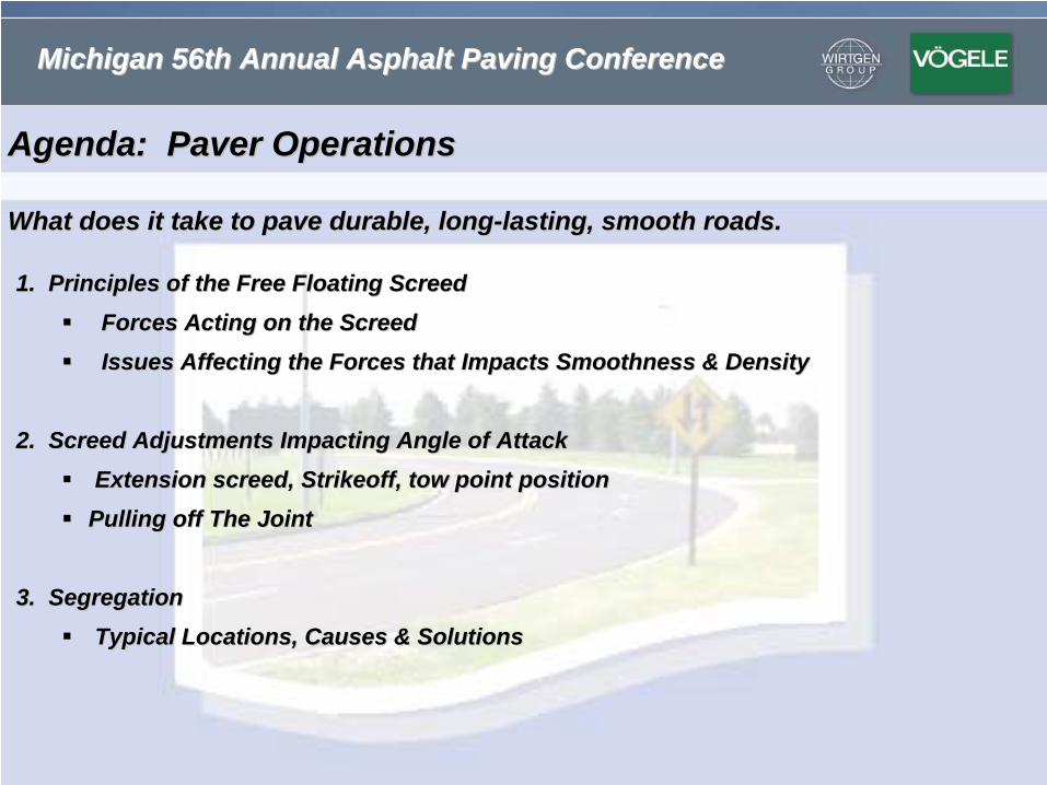
Michigan 56th Annual Asphalt Paving ConferenceMichigan 56th Annual Asphalt Paving Conference
Agenda: Paver OperationsAgenda: Paver Operations
What does it take to pave durable, longWhat does it take to pave durable, long--lasting, smooth roads.lasting, smooth roads.
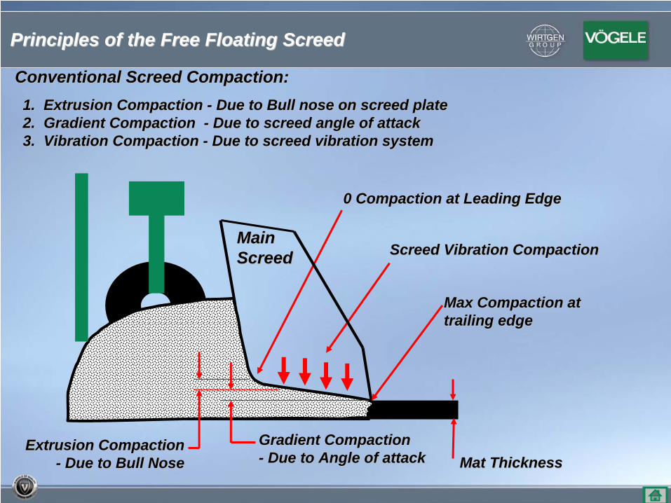
Main Main ScreedScreed
Mat ThicknessMat ThicknessExtrusion Compaction Extrusion Compaction
-- Due to Bull NoseDue to Bull Nose
Screed Vibration CompactionScreed Vibration Compaction
Gradient CompactionGradient Compaction-- Due to Angle of attackDue to Angle of attack
Conventional Screed Compaction:Conventional Screed Compaction:1. Extrusion Compaction 1. Extrusion Compaction -- Due to Bull nose on screed plateDue to Bull nose on screed plate2. Gradient Compaction 2. Gradient Compaction -- Due to screed angle of attack Due to screed angle of attack 3. Vibration Compaction 3. Vibration Compaction -- Due to screed vibration systemDue to screed vibration system
Max Compaction at Max Compaction at trailing edgetrailing edge
0 Compaction at Leading Edge0 Compaction at Leading Edge
Principles of the Free Floating ScreedPrinciples of the Free Floating Screed
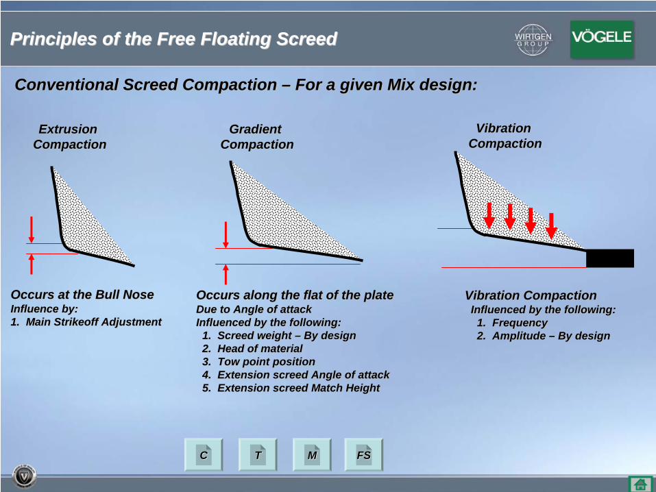
Occurs at the Bull NoseOccurs at the Bull NoseInfluence by:Influence by:1. Main Strikeoff Adjustment1. Main Strikeoff Adjustment
Occurs along the flat of the plateOccurs along the flat of the plateDue to Angle of attackDue to Angle of attackInfluenced by the following:Influenced by the following:
1. Screed weight 1. Screed weight –– By design By design 2. Head of material2. Head of material3. Tow point position3. Tow point position4. Extension screed Angle of attack4. Extension screed Angle of attack5. Extension screed Match Height5. Extension screed Match Height
Vibration CompactionVibration CompactionInfluenced by the following:Influenced by the following:
1. Frequency1. Frequency2. Amplitude 2. Amplitude –– By design By design
ExtrusionExtrusionCompactionCompaction
GradientGradientCompactionCompaction
VibrationVibrationCompactionCompaction
Conventional Screed Compaction Conventional Screed Compaction –– For a given Mix design:For a given Mix design:
Principles of the Free Floating ScreedPrinciples of the Free Floating Screed
CC TT MM FSFS
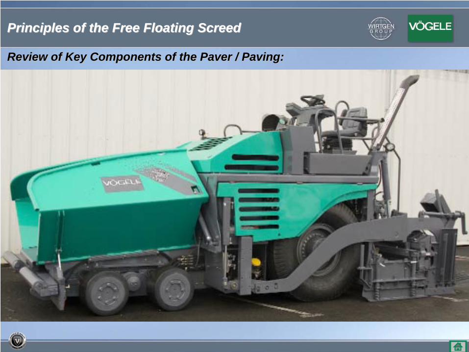
Review of Key Components of the Paver / Paving:Review of Key Components of the Paver / Paving:
Principles of the Free Floating ScreedPrinciples of the Free Floating Screed
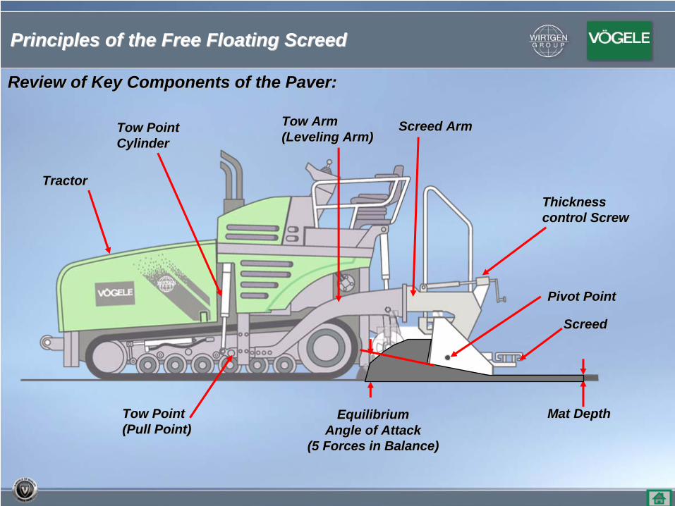
Review of Key Components of the Paver:Review of Key Components of the Paver:
Tow ArmTow Arm(Leveling Arm)(Leveling Arm)
Tow PointTow Point(Pull Point)(Pull Point)
TractorTractor
Mat DepthMat Depth
Thickness Thickness control Screwcontrol Screw
EquilibriumEquilibriumAngle of AttackAngle of Attack
(5 Forces in Balance)(5 Forces in Balance)
Pivot PointPivot Point
Tow PointTow PointCylinderCylinder
ScreedScreed
Screed ArmScreed Arm
Principles of the Free Floating ScreedPrinciples of the Free Floating Screed
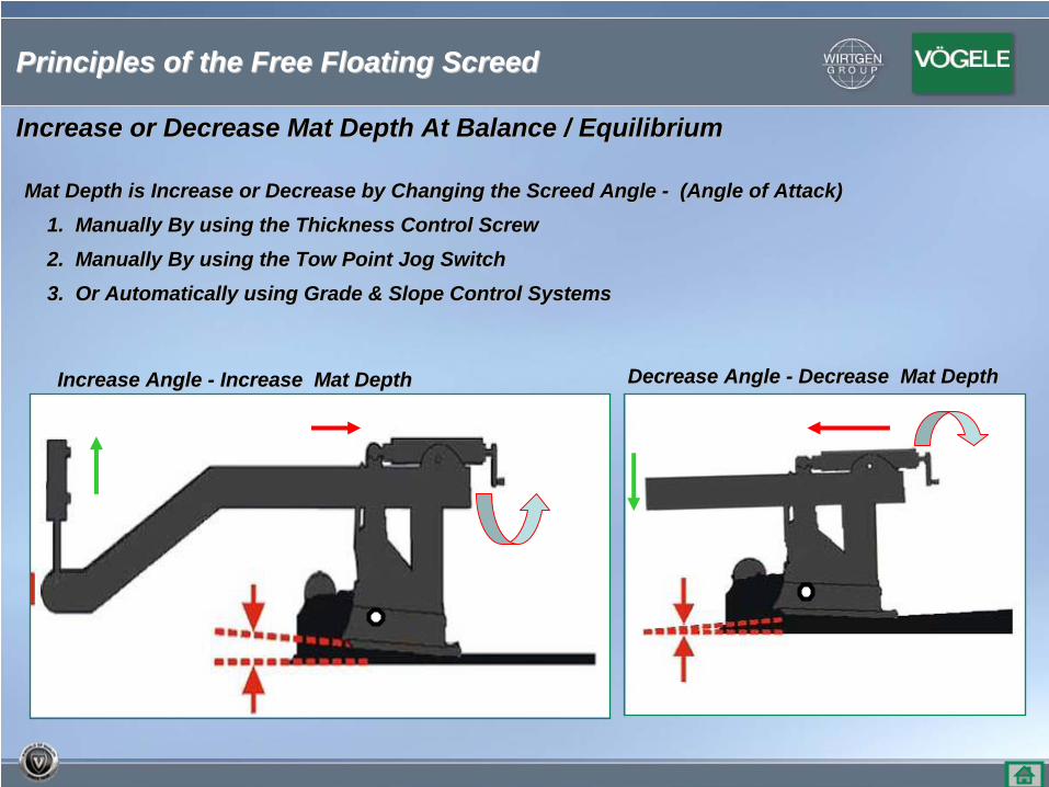
Increase or Decrease Mat Depth At Balance / EquilibriumIncrease or Decrease Mat Depth At Balance / Equilibrium
Mat Depth is Increase or Decrease by Changing the Screed Angle Mat Depth is Increase or Decrease by Changing the Screed Angle -- (Angle of Attack)(Angle of Attack)1. Manually By using the Thickness Control Screw1. Manually By using the Thickness Control Screw
2. Manually By using the Tow Point Jog Switch2. Manually By using the Tow Point Jog Switch
3. Or Automatically using Grade & Slope Control Systems3. Or Automatically using Grade & Slope Control Systems
Decrease Angle Decrease Angle -- Decrease Mat DepthDecrease Mat DepthIncrease Angle Increase Angle -- Increase Mat DepthIncrease Mat Depth
Principles of the Free Floating ScreedPrinciples of the Free Floating Screed
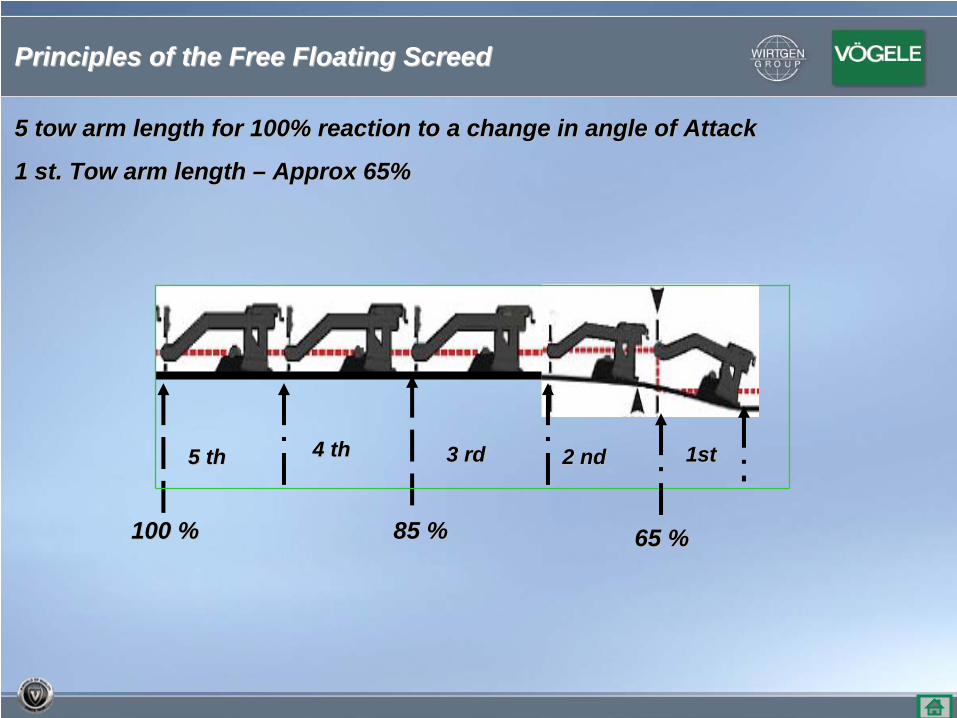
5 tow arm length for 100% reaction to a change in angle of Attac5 tow arm length for 100% reaction to a change in angle of Attackk
1 1 stst. Tow arm length . Tow arm length –– Approx 65%Approx 65%
2 2 ndnd 1st1st3 rd3 rd4 4 thth5 5 thth
65 %65 %85 %85 %100 %100 %
Principles of the Free Floating ScreedPrinciples of the Free Floating Screed
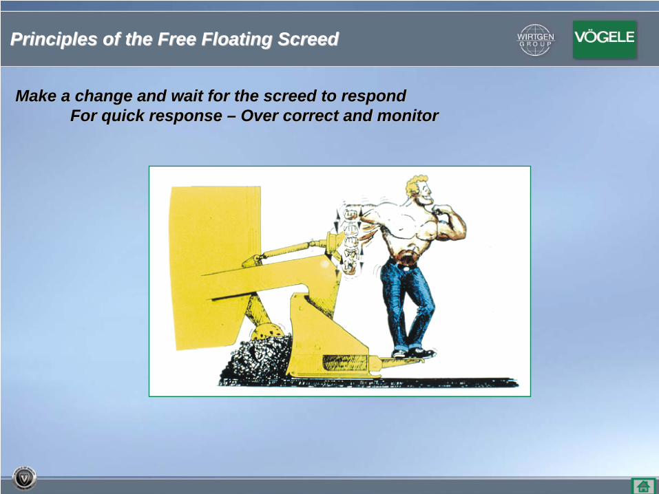
Make a change and wait for the screed to respondMake a change and wait for the screed to respondFor quick response For quick response –– Over correct and monitorOver correct and monitor
Principles of the Free Floating ScreedPrinciples of the Free Floating Screed
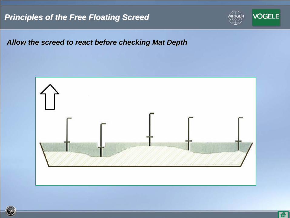
Allow the screed to react before checking Mat DepthAllow the screed to react before checking Mat Depth
Principles of the Free Floating ScreedPrinciples of the Free Floating Screed
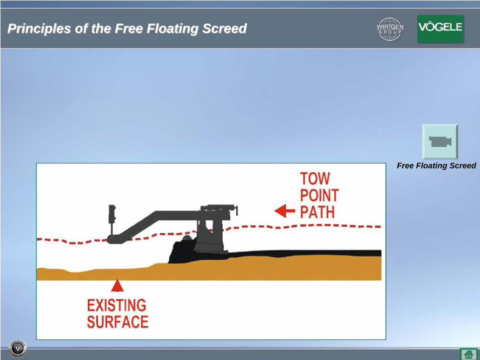
Free Floating ScreedFree Floating Screed
Principles of the Free Floating ScreedPrinciples of the Free Floating Screed
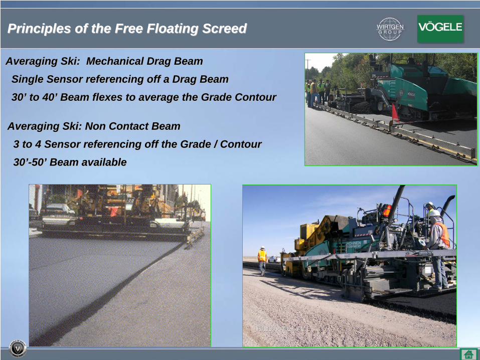
Averaging Ski: Mechanical Drag BeamAveraging Ski: Mechanical Drag Beam
Single Sensor referencing off a Drag BeamSingle Sensor referencing off a Drag Beam
3030’’ to 40to 40’’ Beam flexes to average the Grade ContourBeam flexes to average the Grade Contour
Principles of the Free Floating ScreedPrinciples of the Free Floating Screed
Averaging Ski: Non Contact BeamAveraging Ski: Non Contact Beam
3 to 4 Sensor referencing off the Grade / Contour3 to 4 Sensor referencing off the Grade / Contour
3030’’--5050’’ Beam availableBeam available
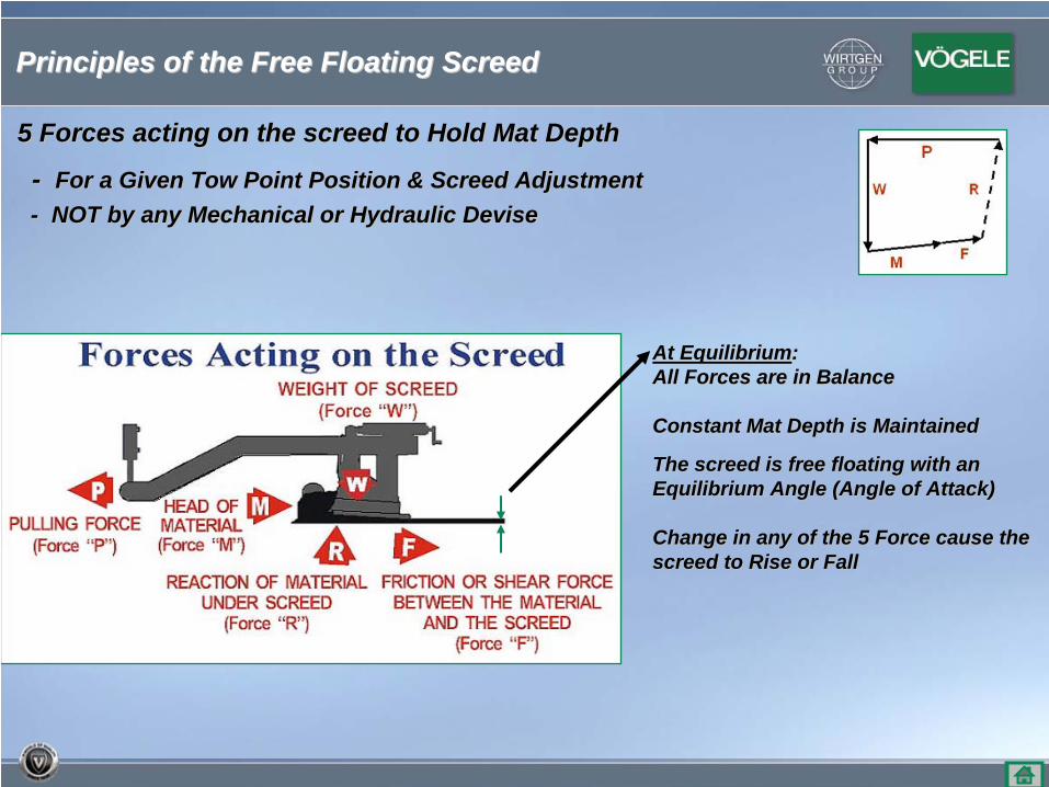
At EquilibriumAt Equilibrium::All Forces are in BalanceAll Forces are in Balance
Constant Mat Depth is MaintainedConstant Mat Depth is Maintained
The screed is free floating with an The screed is free floating with an Equilibrium Angle (Angle of Attack)Equilibrium Angle (Angle of Attack)
Change in any of the 5 Force cause the Change in any of the 5 Force cause the screed to Rise or Fallscreed to Rise or Fall
5 Forces acting on the screed to Hold Mat Depth5 Forces acting on the screed to Hold Mat Depth
-- For a Given Tow Point Position & Screed AdjustmentFor a Given Tow Point Position & Screed Adjustment-- NOT by any Mechanical or Hydraulic DeviseNOT by any Mechanical or Hydraulic Devise
Principles of the Free Floating ScreedPrinciples of the Free Floating Screed
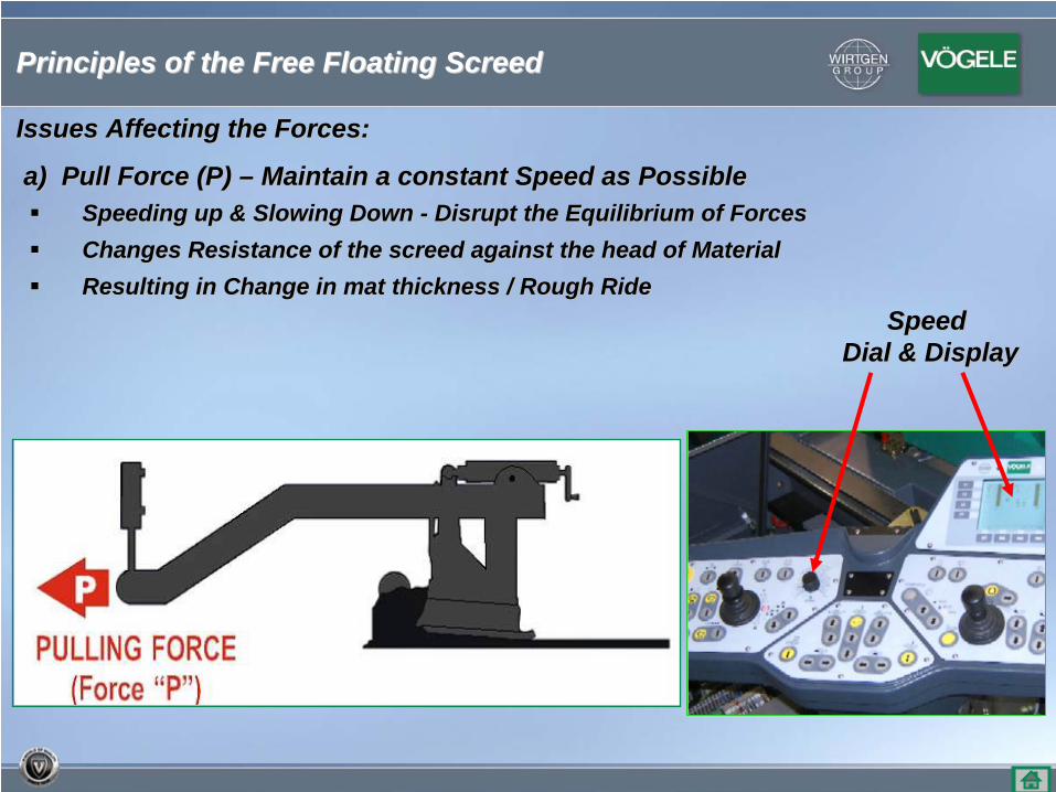
Issues Affecting the Forces:Issues Affecting the Forces:
a) Pull Force (P) a) Pull Force (P) –– Maintain a constant Speed as PossibleMaintain a constant Speed as PossibleSpeeding up & Slowing Down Speeding up & Slowing Down -- Disrupt the Equilibrium of ForcesDisrupt the Equilibrium of ForcesChanges Resistance of the screed against the head of MaterialChanges Resistance of the screed against the head of MaterialResulting in Change in mat thickness / Rough RideResulting in Change in mat thickness / Rough Ride
Speed Speed Dial & DisplayDial & Display
Principles of the Free Floating ScreedPrinciples of the Free Floating Screed
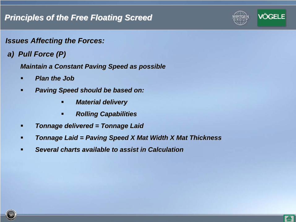
Issues Affecting the Forces:Issues Affecting the Forces:
a) Pull Force (P)a) Pull Force (P)Maintain a Constant Paving Speed as possibleMaintain a Constant Paving Speed as possible
Plan the JobPlan the Job
Paving Speed should be based on:Paving Speed should be based on:
Material delivery Material delivery
Rolling CapabilitiesRolling Capabilities
Tonnage delivered = Tonnage Laid Tonnage delivered = Tonnage Laid
Tonnage Laid = Paving Speed X Mat Width X Mat Thickness Tonnage Laid = Paving Speed X Mat Width X Mat Thickness
Several charts available to assist in Calculation Several charts available to assist in Calculation
Principles of the Free Floating ScreedPrinciples of the Free Floating Screed
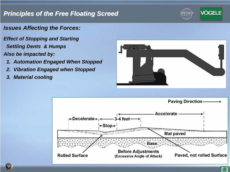
Issues Affecting the Forces:Issues Affecting the Forces:
Effect of Stopping and StartingEffect of Stopping and StartingSettling Dents & HumpsSettling Dents & Humps
Also be impacted by:Also be impacted by:1. Automation Engaged When Stopped1. Automation Engaged When Stopped2. Vibration Engaged when Stopped2. Vibration Engaged when Stopped3. Material cooling3. Material cooling
Principles of the Free Floating ScreedPrinciples of the Free Floating Screed
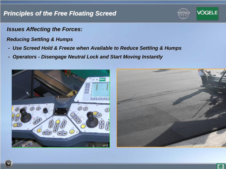
Issues Affecting the Forces:Issues Affecting the Forces:
Reducing Settling & HumpsReducing Settling & Humps
-- Use Screed Hold & Freeze when Available to Reduce Settling & HUse Screed Hold & Freeze when Available to Reduce Settling & Humpsumps
-- Operators Operators -- Disengage Neutral Lock and Start Moving Instantly Disengage Neutral Lock and Start Moving Instantly
Principles of the Free Floating ScreedPrinciples of the Free Floating Screed
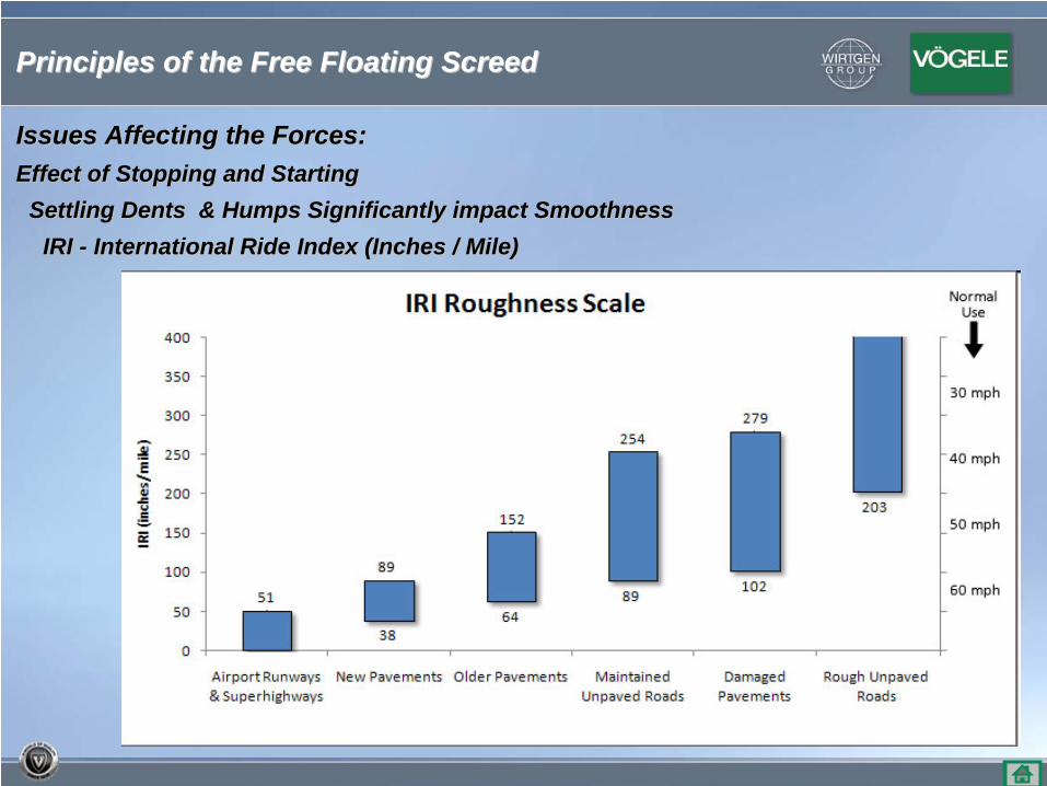
Issues Affecting the Forces:Issues Affecting the Forces:Effect of Stopping and StartingEffect of Stopping and Starting
Settling Dents & Humps Significantly impact SmoothnessSettling Dents & Humps Significantly impact SmoothnessIRI IRI -- International Ride Index (Inches / Mile)International Ride Index (Inches / Mile)
Principles of the Free Floating ScreedPrinciples of the Free Floating Screed
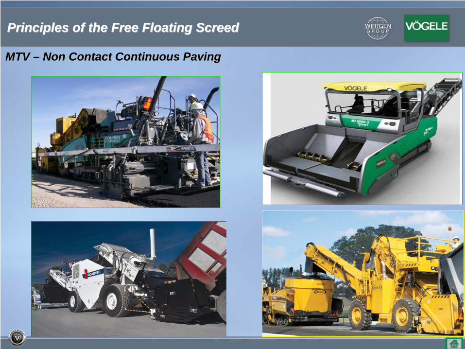
MTV MTV –– Non Contact Continuous PavingNon Contact Continuous Paving
Principles of the Free Floating ScreedPrinciples of the Free Floating Screed
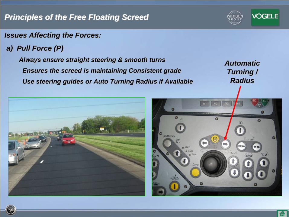
Issues Affecting the Forces:Issues Affecting the Forces:
a) Pull Force (P)a) Pull Force (P)Always ensure straight steering & smooth turnsAlways ensure straight steering & smooth turns
Ensures the screed is maintaining Consistent gradeEnsures the screed is maintaining Consistent grade
Use steering guides or Auto Turning Radius if AvailableUse steering guides or Auto Turning Radius if Available
Automatic Automatic Turning / Turning / RadiusRadius
Principles of the Free Floating ScreedPrinciples of the Free Floating Screed
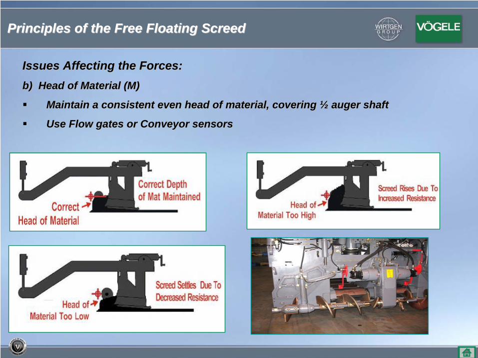
Issues Affecting the Forces:Issues Affecting the Forces:b) Head of Material (M)b) Head of Material (M)
Maintain a consistent even head of material, covering Maintain a consistent even head of material, covering ½½ auger shaftauger shaft
Use Flow gates or Conveyor sensorsUse Flow gates or Conveyor sensors
Principles of the Free Floating ScreedPrinciples of the Free Floating Screed
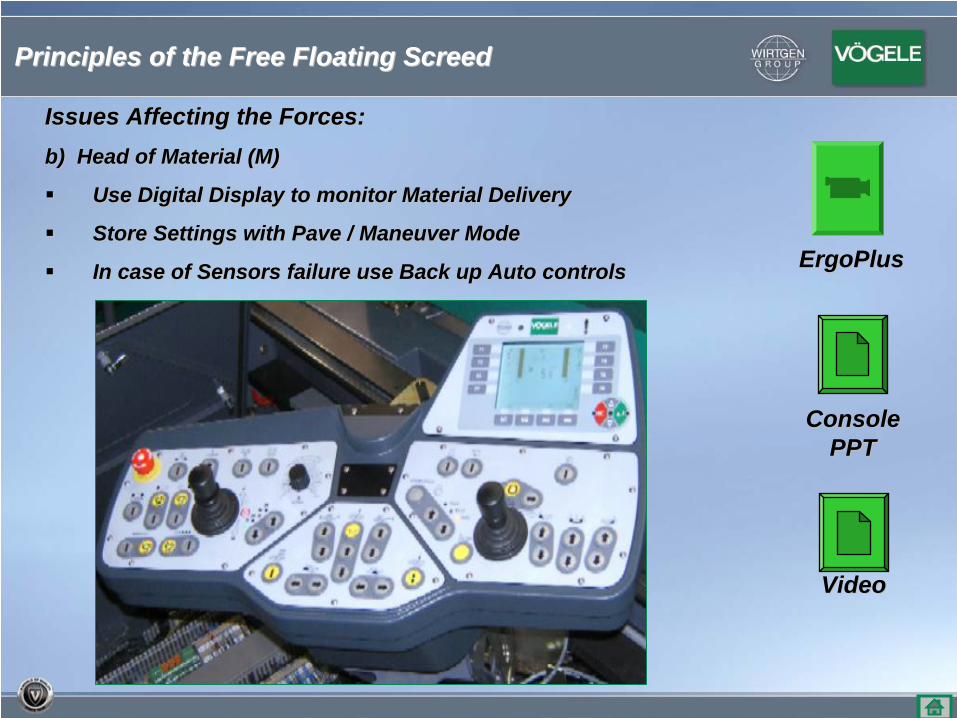
Issues Affecting the Forces:Issues Affecting the Forces:b) Head of Material (M)b) Head of Material (M)
Use Digital Display to monitor Material DeliveryUse Digital Display to monitor Material Delivery
Store Settings with Pave / Maneuver ModeStore Settings with Pave / Maneuver Mode
In case of Sensors failure use Back up Auto controlsIn case of Sensors failure use Back up Auto controls ErgoPlusErgoPlus
ConsoleConsolePPTPPT
VideoVideo
Principles of the Free Floating ScreedPrinciples of the Free Floating Screed
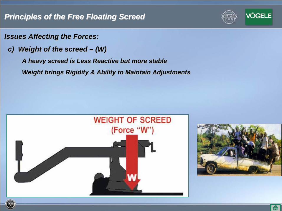
Issues Affecting the Forces:Issues Affecting the Forces:
c) Weight of the screed c) Weight of the screed –– (W)(W)A heavy screed is Less Reactive but more stableA heavy screed is Less Reactive but more stable
Weight brings Rigidity & Ability to Maintain AdjustmentsWeight brings Rigidity & Ability to Maintain Adjustments
Principles of the Free Floating ScreedPrinciples of the Free Floating Screed
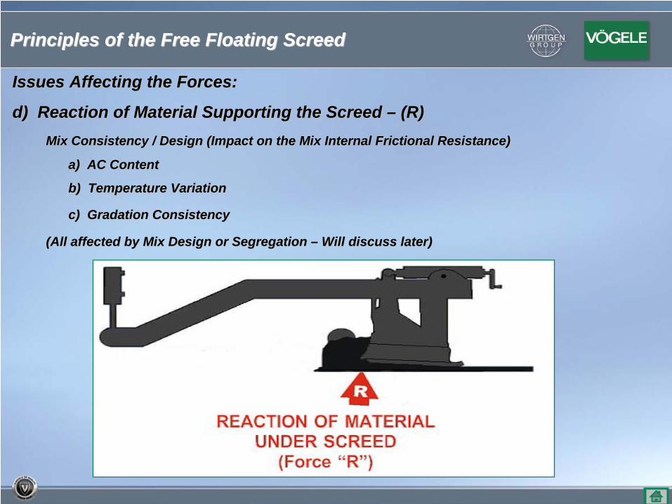
Issues Affecting the Forces:Issues Affecting the Forces:
d) Reaction of Material Supporting the Screed d) Reaction of Material Supporting the Screed –– (R)(R)Mix Consistency / Design (Impact on the Mix Internal Frictional Mix Consistency / Design (Impact on the Mix Internal Frictional Resistance)Resistance)
a) AC Contenta) AC Content
b) Temperature Variationb) Temperature Variation
c) Gradation Consistencyc) Gradation Consistency
(All affected by Mix Design or Segregation (All affected by Mix Design or Segregation –– Will discuss later)Will discuss later)
Principles of the Free Floating ScreedPrinciples of the Free Floating Screed
Issues Affecting the Forces:Issues Affecting the Forces:
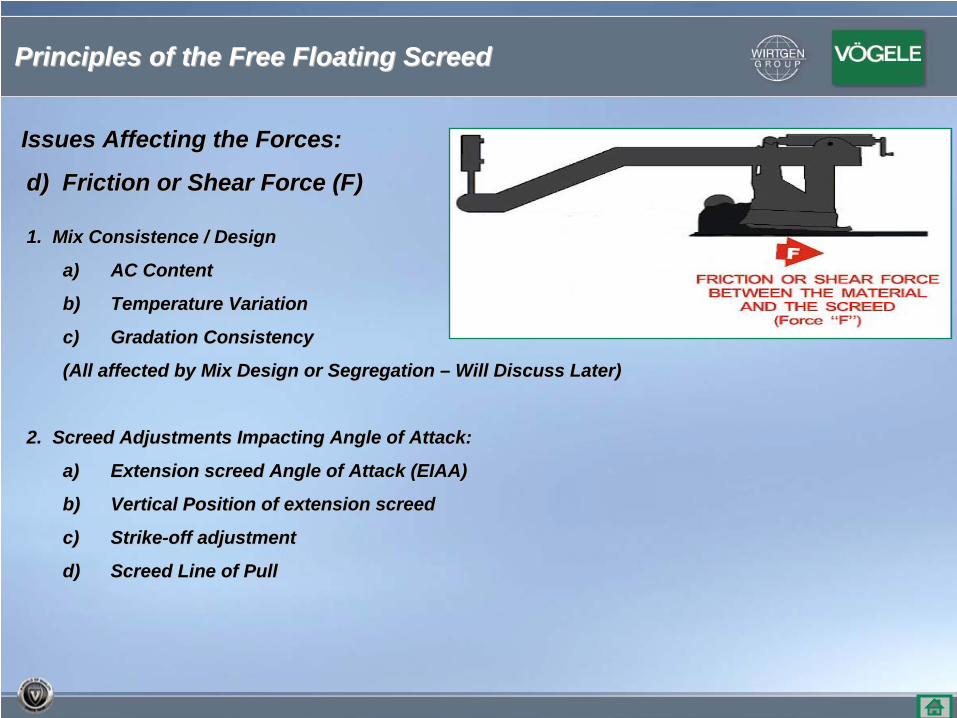
d) Friction or Shear Force (F)d) Friction or Shear Force (F)
1. Mix Consistence / Design1. Mix Consistence / Design
a)a) AC ContentAC Content
b)b) Temperature VariationTemperature Variation
c)c) Gradation ConsistencyGradation Consistency
(All affected by Mix Design or Segregation (All affected by Mix Design or Segregation –– Will Discuss Later)Will Discuss Later)
2. Screed Adjustments Impacting Angle of Attack:2. Screed Adjustments Impacting Angle of Attack:
a) a) Extension screed Angle of Attack (EIAA)Extension screed Angle of Attack (EIAA)
b) b) Vertical Position of extension screedVertical Position of extension screed
c) c) StrikeStrike--off adjustmentoff adjustment
d)d) Screed Line of PullScreed Line of Pull
Principles of the Free Floating ScreedPrinciples of the Free Floating Screed
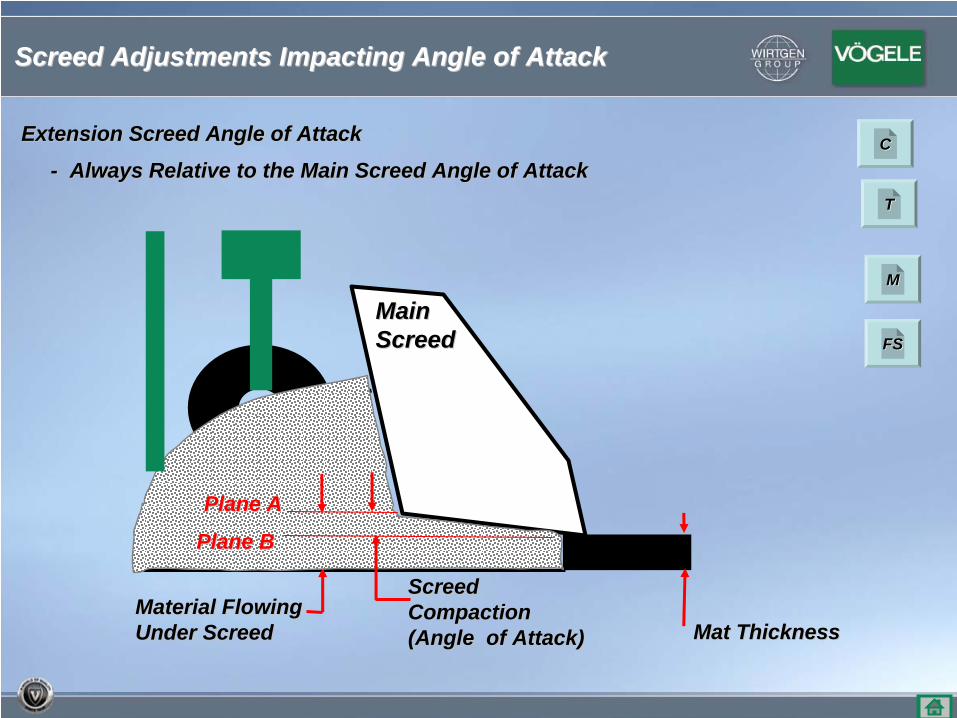
Main Main ScreedScreed
Mat ThicknessMat ThicknessMaterial Flowing Material Flowing Under ScreedUnder Screed
Screed Screed CompactionCompaction(Angle of Attack)(Angle of Attack)
Extension Screed Angle of AttackExtension Screed Angle of Attack
-- Always Relative to the Main Screed Angle of AttackAlways Relative to the Main Screed Angle of Attack
Plane APlane A
Plane BPlane B
Screed Adjustments Impacting Angle of AttackScreed Adjustments Impacting Angle of Attack
CC
TT
MM
FSFS
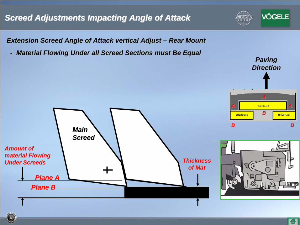
Amount of Amount of material Flowing material Flowing Under ScreedsUnder Screeds
Main Main ScreedScreed
LH & RH LH & RH ExtensionExtension
Thickness Thickness of Matof Mat
Plane APlane APlane BPlane B
Extension Screed Angle of Attack vertical Adjust Extension Screed Angle of Attack vertical Adjust –– Rear MountRear Mount
-- Material Flowing Under all Screed Sections must Be EqualMaterial Flowing Under all Screed Sections must Be EqualPaving Paving
DirectionDirection
BB BB
BB
AA
AAAA
Screed Adjustments Impacting Angle of AttackScreed Adjustments Impacting Angle of Attack
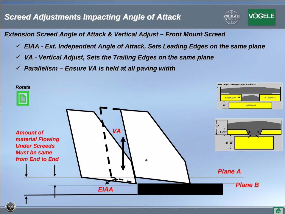
EIAA EIAA -- Ext. Independent Angle of Attack, Sets Leading Edges on the samExt. Independent Angle of Attack, Sets Leading Edges on the same planee plane
VA VA -- Vertical Adjust, Sets the Trailing Edges on the same planeVertical Adjust, Sets the Trailing Edges on the same plane
Parallelism Parallelism –– Ensure VA is held at all paving widthEnsure VA is held at all paving width
VAVA
EIAAEIAA
Plane APlane A
Plane BPlane B
Main Main ScreedScreed
Amount of Amount of material Flowing material Flowing Under ScreedsUnder ScreedsMust be same Must be same from End to Endfrom End to End
Extension Screed Angle of Attack & Vertical Adjust Extension Screed Angle of Attack & Vertical Adjust –– Front Mount ScreedFront Mount Screed
Screed Adjustments Impacting Angle of AttackScreed Adjustments Impacting Angle of Attack
RotateRotate
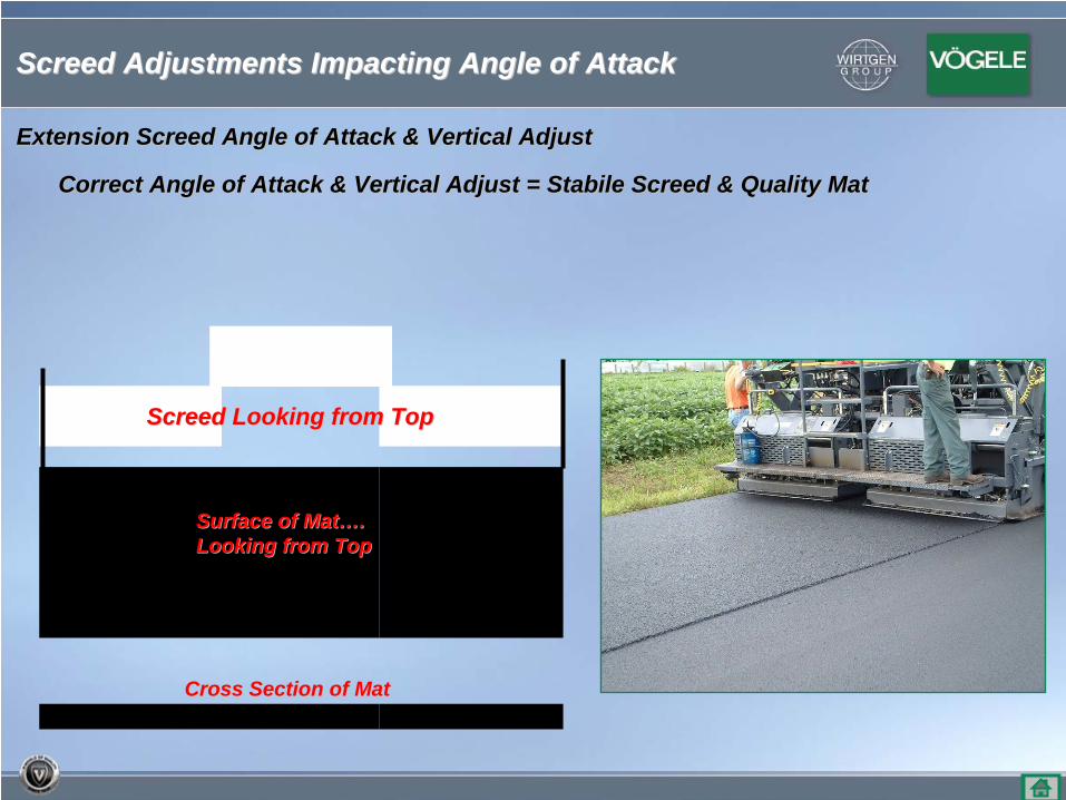
Correct Angle of Attack & Vertical Adjust = Stabile Screed & QuaCorrect Angle of Attack & Vertical Adjust = Stabile Screed & Quality Matlity Mat
Cross Section of MatCross Section of Mat
Surface of MatSurface of Mat……. . Looking from TopLooking from Top
Screed Looking from TopScreed Looking from Top
Extension Screed Angle of Attack & Vertical AdjustExtension Screed Angle of Attack & Vertical Adjust
Screed Adjustments Impacting Angle of AttackScreed Adjustments Impacting Angle of Attack
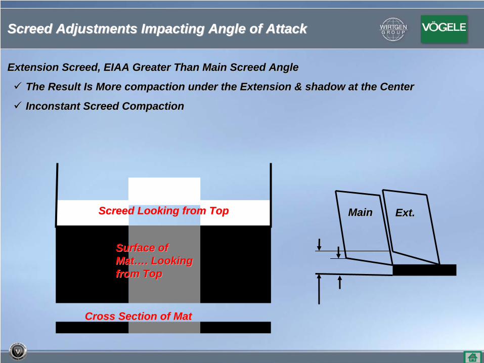
Extension Screed, EIAA Greater Than Main Screed AngleExtension Screed, EIAA Greater Than Main Screed Angle
The Result Is More compaction under the Extension & shadow at thThe Result Is More compaction under the Extension & shadow at the Centere Center
Inconstant Screed CompactionInconstant Screed Compaction
Cross Section of MatCross Section of Mat
Surface of Surface of MatMat……. Looking . Looking from Topfrom Top
Screed Looking from TopScreed Looking from Top MainMain Ext.Ext.
Screed Adjustments Impacting Angle of AttackScreed Adjustments Impacting Angle of Attack
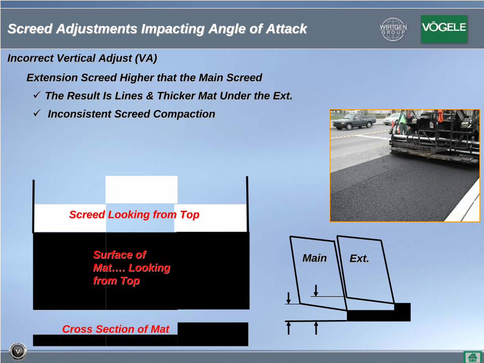
Extension Screed Higher that the Main ScreedExtension Screed Higher that the Main Screed
The Result Is Lines & Thicker Mat Under the Ext.The Result Is Lines & Thicker Mat Under the Ext.
Inconsistent Screed CompactionInconsistent Screed Compaction
Cross Section of MatCross Section of Mat
Surface of Surface of MatMat……. Looking . Looking from Topfrom Top
Screed Looking from TopScreed Looking from Top
MainMain Ext.Ext.
Incorrect Vertical Adjust (VA)Incorrect Vertical Adjust (VA)
Screed Adjustments Impacting Angle of AttackScreed Adjustments Impacting Angle of Attack
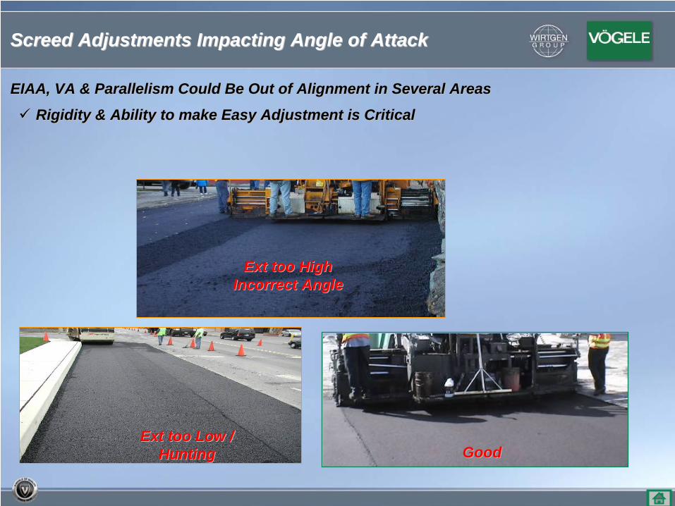
EIAA, VA & Parallelism Could Be Out of Alignment in Several AreaEIAA, VA & Parallelism Could Be Out of Alignment in Several Areass
Rigidity & Ability to make Easy Adjustment is CriticalRigidity & Ability to make Easy Adjustment is Critical
GoodGood
Ext too HighExt too HighIncorrect AngleIncorrect Angle
Ext too Low / Ext too Low / HuntingHunting
Screed Adjustments Impacting Angle of AttackScreed Adjustments Impacting Angle of Attack
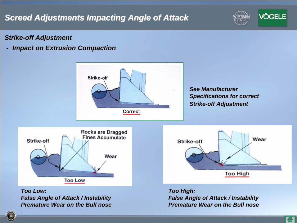
StrikeStrike--off Adjustment off Adjustment -- Impact on Extrusion CompactionImpact on Extrusion Compaction
See ManufacturerSee ManufacturerSpecifications for correctSpecifications for correctStrikeStrike--off Adjustmentoff Adjustment
Too High:Too High:False Angle of Attack / InstabilityFalse Angle of Attack / InstabilityPremature Wear on the Bull nosePremature Wear on the Bull nose
Too Low:Too Low:False Angle of Attack / InstabilityFalse Angle of Attack / InstabilityPremature Wear on the Bull nosePremature Wear on the Bull nose
Screed Adjustments Impacting Angle of AttackScreed Adjustments Impacting Angle of Attack
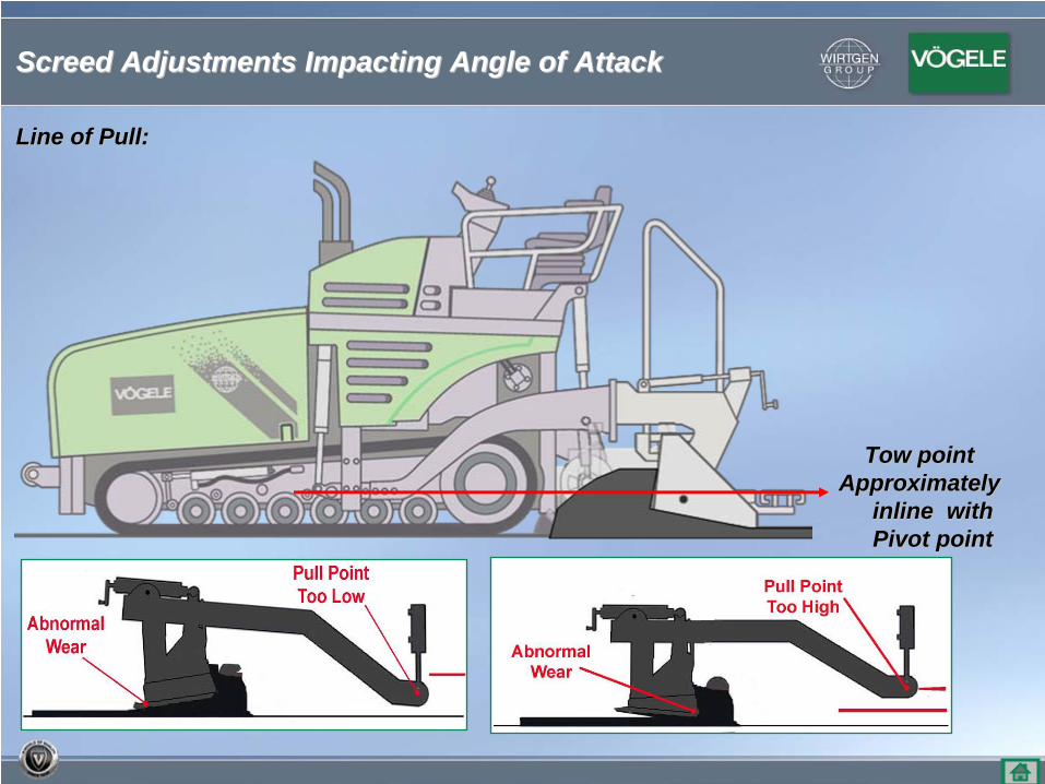
Tow pointTow pointApproximately Approximately
inline with inline with Pivot pointPivot point
Line of Pull:Line of Pull:
Screed Adjustments Impacting Angle of AttackScreed Adjustments Impacting Angle of Attack
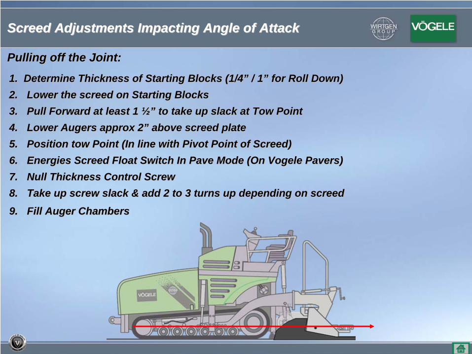
Pulling off the Joint:Pulling off the Joint:
1. Determine Thickness of Starting Blocks (1/41. Determine Thickness of Starting Blocks (1/4”” / 1/ 1”” for Roll Down)for Roll Down)2.2. Lower the screed on Starting BlocksLower the screed on Starting Blocks3.3. Pull Forward at least 1 Pull Forward at least 1 ½”½” to take up slack at Tow Pointto take up slack at Tow Point4.4. Lower Augers approx 2Lower Augers approx 2”” above screed plateabove screed plate5.5. Position tow Point (In line with Pivot Point of Screed)Position tow Point (In line with Pivot Point of Screed)6.6. Energies Screed Float Switch In Pave Mode (On Vogele Pavers)Energies Screed Float Switch In Pave Mode (On Vogele Pavers)7.7. Null Thickness Control ScrewNull Thickness Control Screw8.8. Take up screw slack & add 2 to 3 turns up depending on screedTake up screw slack & add 2 to 3 turns up depending on screed
9.9. Fill Auger ChambersFill Auger Chambers
Screed Adjustments Impacting Angle of AttackScreed Adjustments Impacting Angle of Attack
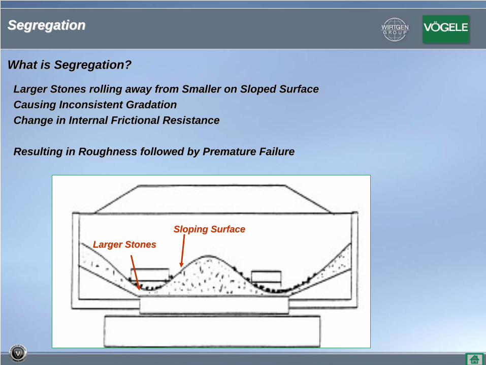
What is Segregation?What is Segregation?
Larger Stones rolling away from Smaller on Sloped SurfaceLarger Stones rolling away from Smaller on Sloped SurfaceCausing Inconsistent GradationCausing Inconsistent GradationChange in Internal Frictional ResistanceChange in Internal Frictional Resistance
Resulting in Roughness followed by Premature FailureResulting in Roughness followed by Premature Failure
Larger StonesLarger StonesSloping SurfaceSloping Surface
Segregation Segregation
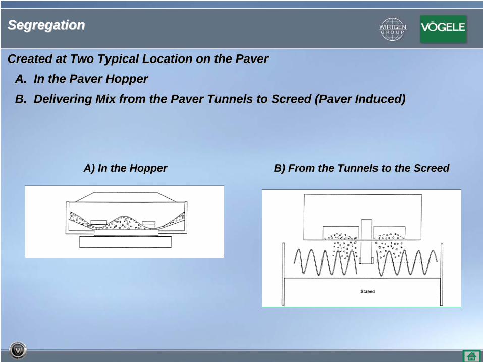
Created at Two Typical Location on the PaverCreated at Two Typical Location on the Paver
A) In the HopperA) In the Hopper
A. In the Paver HopperA. In the Paver Hopper
B. Delivering Mix from the Paver Tunnels to Screed (Paver InducB. Delivering Mix from the Paver Tunnels to Screed (Paver Induced)ed)
B) From the Tunnels to the ScreedB) From the Tunnels to the Screed
Segregation Segregation
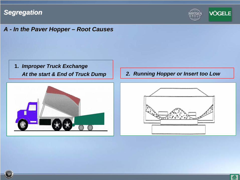
A A -- In the Paver Hopper In the Paver Hopper –– Root CausesRoot Causes
1. Improper Truck ExchangeAt the start & End of Truck Dump 2. Running Hopper or Insert too Low
Segregation Segregation
XX
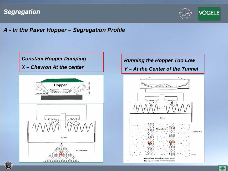
A A -- In the Paver Hopper In the Paver Hopper –– Segregation ProfileSegregation Profile
YY YY
Running the Hopper Too LowRunning the Hopper Too Low
Y Y –– At the Center of the TunnelAt the Center of the Tunnel
Constant Hopper DumpingConstant Hopper Dumping
X X –– Chevron At the center Chevron At the center
Segregation Segregation
A A -- In the Paver Hopper In the Paver Hopper –– Segregation ProfileSegregation Profile
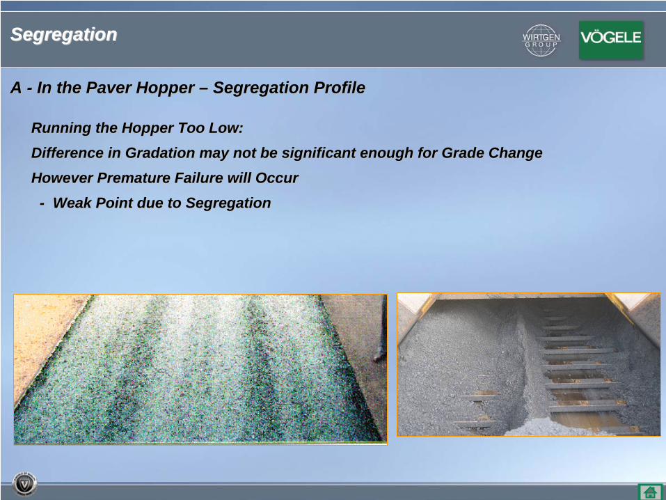
Running the Hopper Too Low:Running the Hopper Too Low:
Difference in Gradation may not be significant enough for Grade Difference in Gradation may not be significant enough for Grade ChangeChange
However Premature Failure will OccurHowever Premature Failure will Occur
-- Weak Point due to Segregation Weak Point due to Segregation
Segregation Segregation
A A -- In the Paver Hopper In the Paver Hopper –– Segregation ProfileSegregation Profile
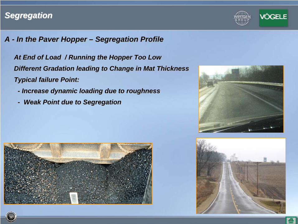
At End of Load / Running the Hopper Too LowAt End of Load / Running the Hopper Too Low
Different Gradation leading to Change in Mat ThicknessDifferent Gradation leading to Change in Mat Thickness
Typical failure Point:Typical failure Point:
-- Increase dynamic loading due to roughnessIncrease dynamic loading due to roughness
-- Weak Point due to Segregation Weak Point due to Segregation
Segregation Segregation
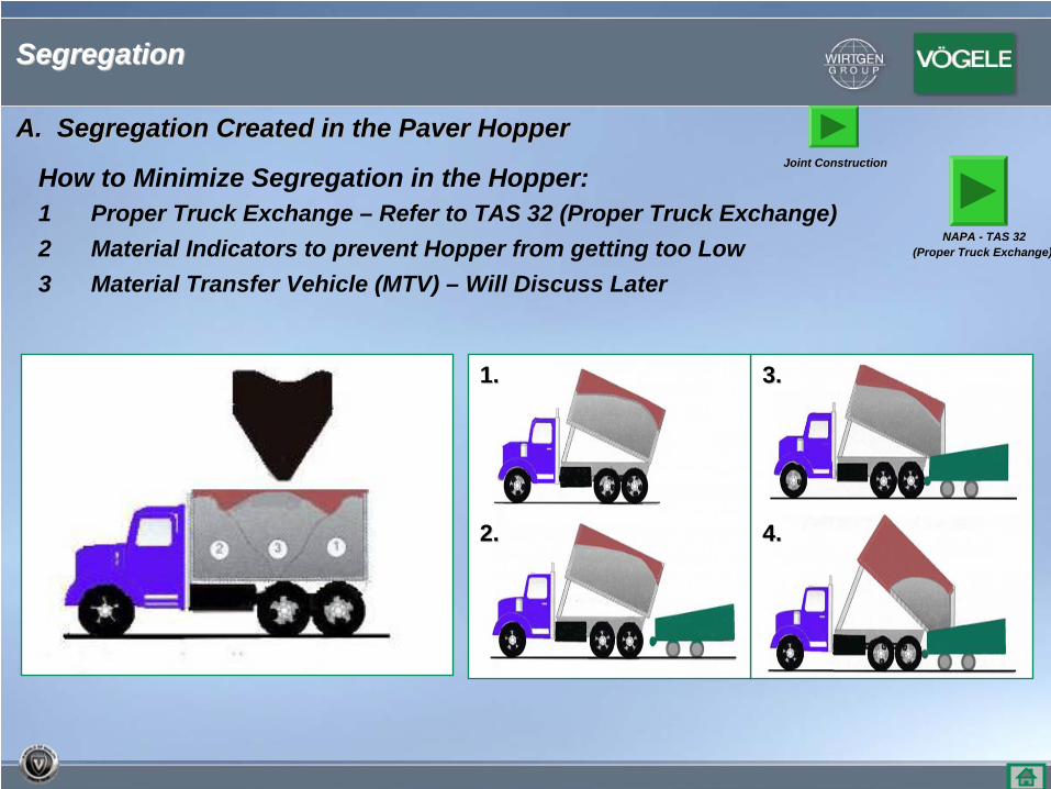
A. Segregation Created in the Paver HopperA. Segregation Created in the Paver Hopper
How to Minimize Segregation in the Hopper:1 Proper Truck Exchange – Refer to TAS 32 (Proper Truck Exchange)2 Material Indicators to prevent Hopper from getting too Low3 Material Transfer Vehicle (MTV) – Will Discuss Later
1.1.
2.2. 4.4.
3.3.
Segregation Segregation
NAPA NAPA -- TAS 32(Proper Truck Exchange)
Joint ConstructionJoint Construction
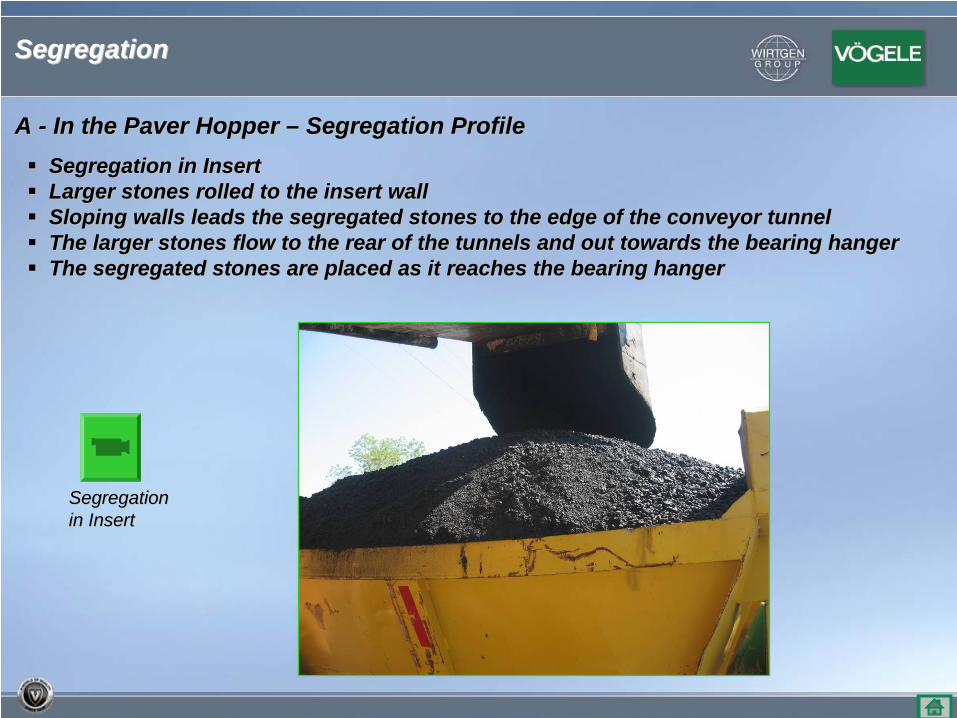
A A -- In the Paver Hopper In the Paver Hopper –– Segregation ProfileSegregation ProfileSegregation in InsertSegregation in InsertLarger stones rolled to the insert wallLarger stones rolled to the insert wallSloping walls leads the segregated stones to the edge of the cSloping walls leads the segregated stones to the edge of the conveyor tunnelonveyor tunnelThe larger stones flow to the rear of the tunnels and out towaThe larger stones flow to the rear of the tunnels and out towards the bearing hangerrds the bearing hangerThe segregated stones are placed as it reaches the bearing hanThe segregated stones are placed as it reaches the bearing hangerger
SegregationSegregationin Insertin Insert
Segregation Segregation
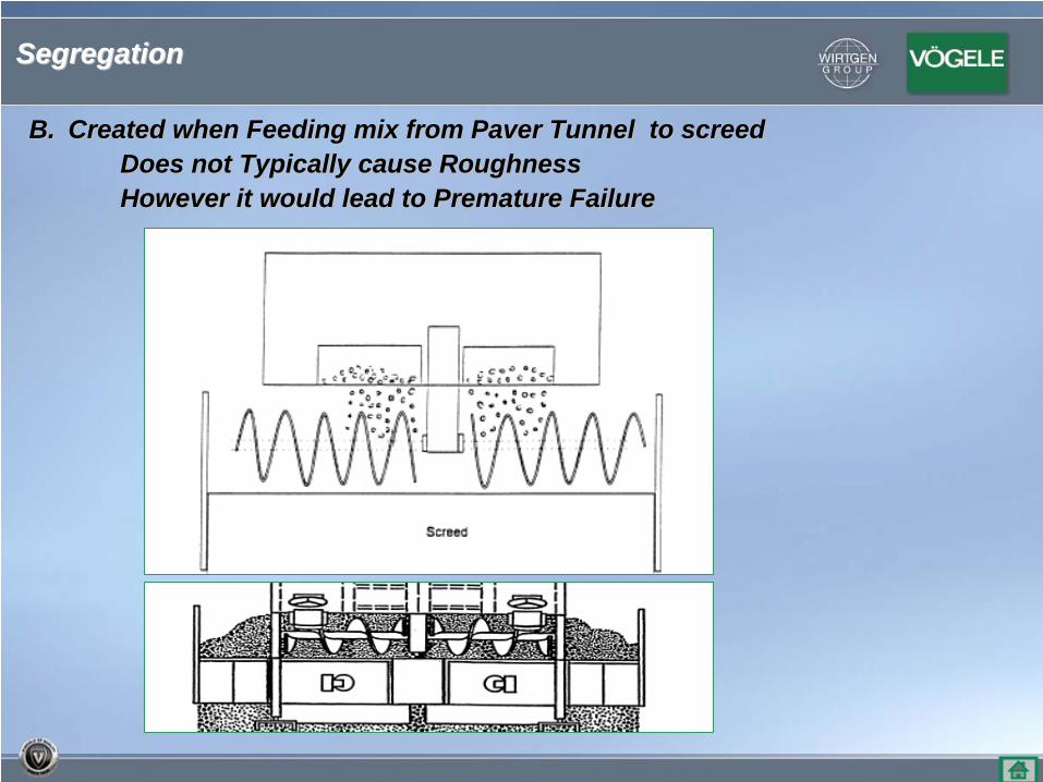
B.B. Created when Feeding mix from Paver Tunnel to screedCreated when Feeding mix from Paver Tunnel to screedDoes not Typically cause RoughnessDoes not Typically cause RoughnessHowever it would lead to Premature Failure However it would lead to Premature Failure
Segregation Segregation
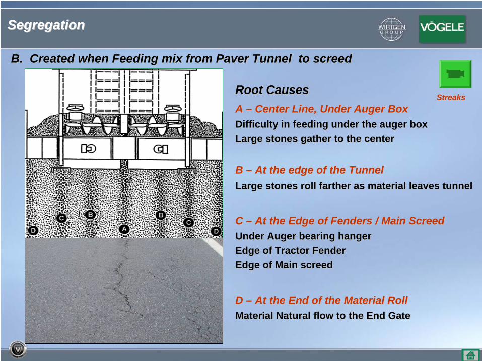
Root CausesRoot CausesA A –– Center Line, Under Auger BoxCenter Line, Under Auger BoxDifficulty in feeding under the auger boxDifficulty in feeding under the auger boxLarge stones gather to the centerLarge stones gather to the center
B B –– At the edge of the TunnelAt the edge of the TunnelLarge stones roll farther as material leaves tunnelLarge stones roll farther as material leaves tunnel
C C –– At the Edge of Fenders / Main ScreedAt the Edge of Fenders / Main ScreedUnder Auger bearing hangerUnder Auger bearing hangerEdge of Tractor FenderEdge of Tractor FenderEdge of Main screedEdge of Main screed
D D –– At the End of the Material RollAt the End of the Material RollMaterial Natural flow to the End GateMaterial Natural flow to the End Gate
B. Created when Feeding mix from Paver Tunnel to screedB. Created when Feeding mix from Paver Tunnel to screed
StreaksStreaks
Segregation Segregation
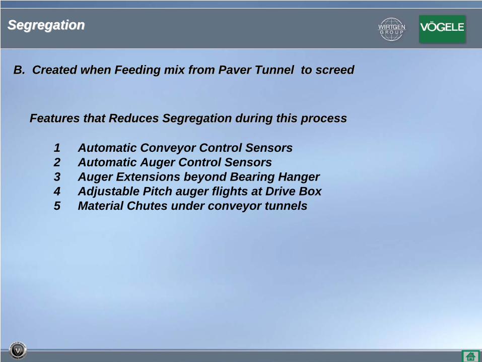
Features that Reduces Segregation during this processFeatures that Reduces Segregation during this process
1 Automatic Conveyor Control Sensors2 Automatic Auger Control Sensors 3 Auger Extensions beyond Bearing Hanger4 Adjustable Pitch auger flights at Drive Box5 Material Chutes under conveyor tunnels
B. Created when Feeding mix from Paver Tunnel to screedB. Created when Feeding mix from Paver Tunnel to screed
Segregation Segregation
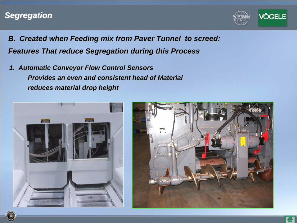
1. Automatic Conveyor Flow Control Sensors1. Automatic Conveyor Flow Control SensorsProvides an even and consistent head of MaterialProvides an even and consistent head of Materialreduces material drop heightreduces material drop height
B.B. Created when Feeding mix from Paver Tunnel to screed:Created when Feeding mix from Paver Tunnel to screed:
Features That reduce Segregation during this ProcessFeatures That reduce Segregation during this Process
Segregation Segregation
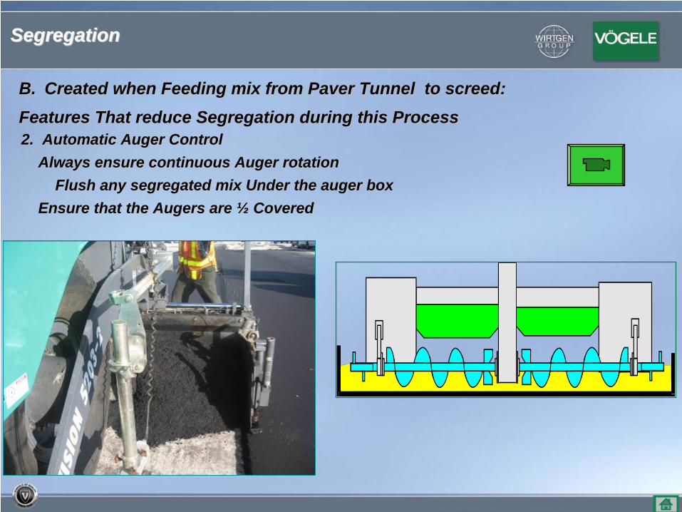
2. Automatic Auger Control2. Automatic Auger ControlAlways ensure continuous Auger rotationAlways ensure continuous Auger rotation
Flush any segregated mix Under the auger boxFlush any segregated mix Under the auger boxEnsure that the Augers are Ensure that the Augers are ½½ CoveredCovered
B.B. Created when Feeding mix from Paver Tunnel to screed:Created when Feeding mix from Paver Tunnel to screed:
Features That reduce Segregation during this ProcessFeatures That reduce Segregation during this Process
Segregation Segregation
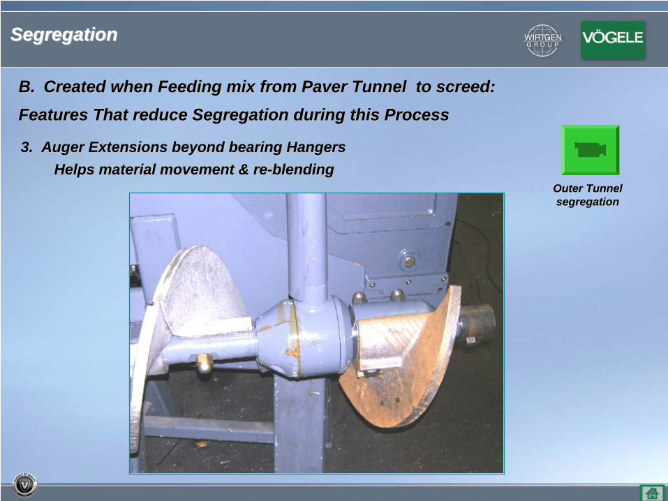
3. Auger Extensions beyond bearing Hangers3. Auger Extensions beyond bearing HangersHelps material movement & reHelps material movement & re--blending blending
B.B. Created when Feeding mix from Paver Tunnel to screed:Created when Feeding mix from Paver Tunnel to screed:
Features That reduce Segregation during this ProcessFeatures That reduce Segregation during this Process
Outer Tunnel Outer Tunnel segregationsegregation
Segregation Segregation
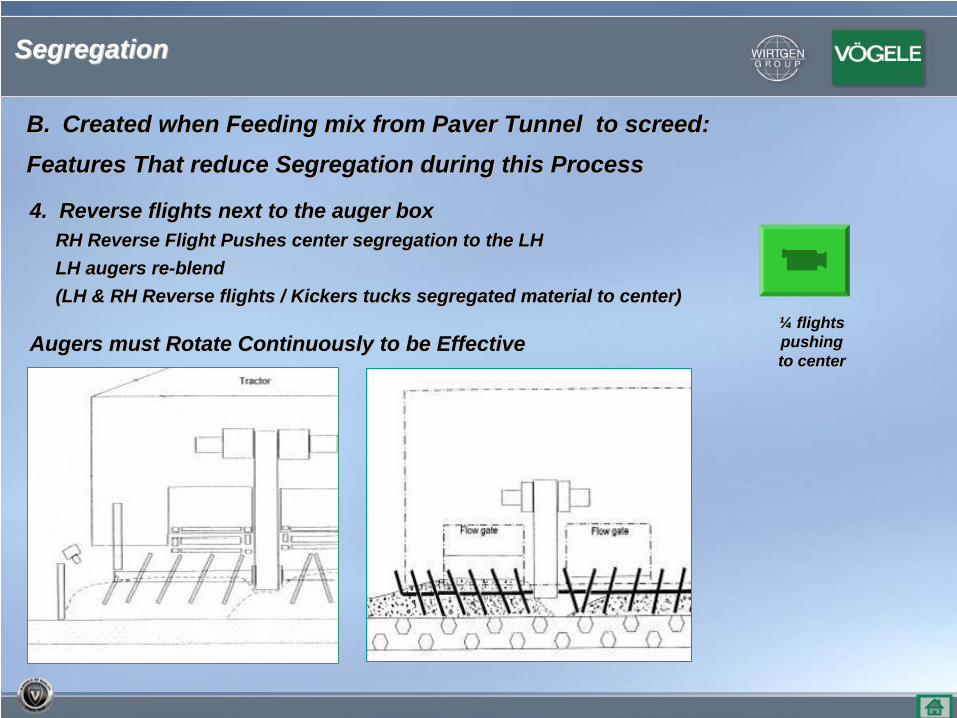
4. Reverse flights next to the auger box4. Reverse flights next to the auger boxRH Reverse Flight Pushes center segregation to the LHRH Reverse Flight Pushes center segregation to the LHLH augers reLH augers re--blendblend(LH & RH Reverse flights / Kickers tucks segregated materia(LH & RH Reverse flights / Kickers tucks segregated material to center)l to center)
Augers must Rotate Continuously to be EffectiveAugers must Rotate Continuously to be Effective
B.B. Created when Feeding mix from Paver Tunnel to screed:Created when Feeding mix from Paver Tunnel to screed:
Features That reduce Segregation during this ProcessFeatures That reduce Segregation during this Process
¼¼ flights flights pushing pushing to centerto center
Segregation Segregation
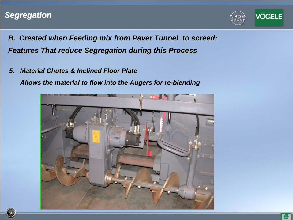
5. Material Chutes & Inclined Floor Plate5. Material Chutes & Inclined Floor Plate
Allows the material to flow into the Augers for reAllows the material to flow into the Augers for re--blendingblending
B.B. Created when Feeding mix from Paver Tunnel to screed:Created when Feeding mix from Paver Tunnel to screed:
Features That reduce Segregation during this ProcessFeatures That reduce Segregation during this Process
Segregation Segregation
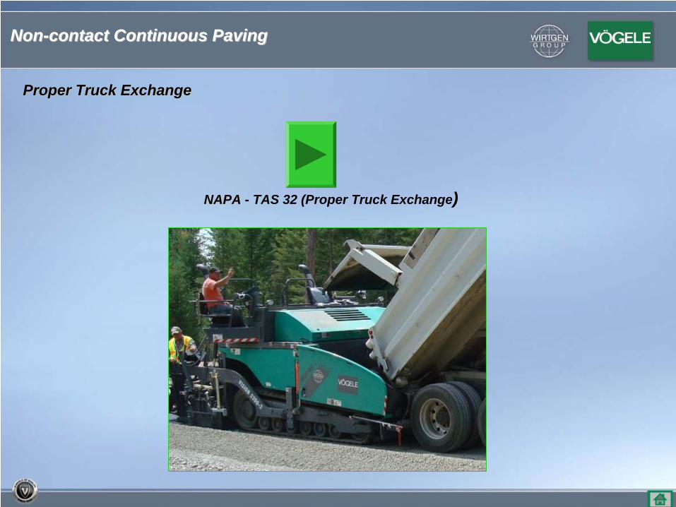
Proper Truck ExchangeProper Truck Exchange
NonNon--contact Continuous Pavingcontact Continuous Paving
NAPA NAPA -- TAS 32 (Proper Truck Exchange)
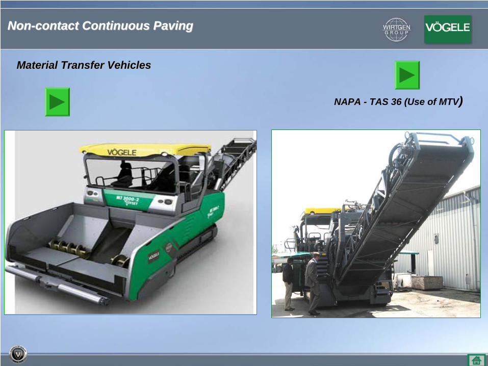
Material Transfer VehiclesMaterial Transfer Vehicles
NAPA NAPA -- TAS 36 (Use of MTV)
NonNon--contact Continuous Pavingcontact Continuous Paving

QuestionsQuestions
Thank YouThank You
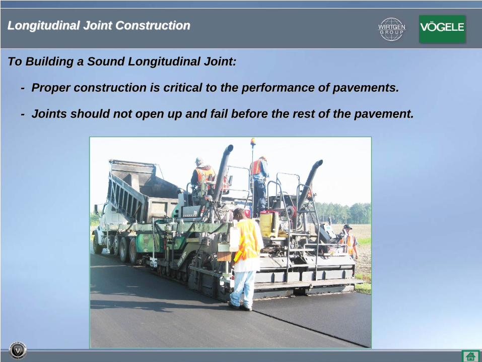
To Building a Sound Longitudinal Joint:To Building a Sound Longitudinal Joint:
-- Proper construction is critical to the performance of pavementProper construction is critical to the performance of pavements.s.
-- Joints should not open up and fail before the rest of the paveJoints should not open up and fail before the rest of the pavement.ment.
Longitudinal Joint ConstructionLongitudinal Joint Construction
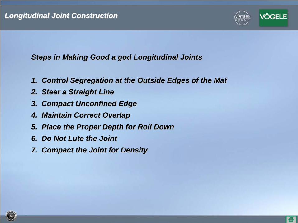
Steps in Making Good a god Longitudinal JointsSteps in Making Good a god Longitudinal Joints
1. Control Segregation at the Outside Edges of the Mat1. Control Segregation at the Outside Edges of the Mat2. Steer a Straight Line2. Steer a Straight Line3. Compact Unconfined Edge3. Compact Unconfined Edge4. Maintain Correct Overlap4. Maintain Correct Overlap5. Place the Proper Depth for Roll Down5. Place the Proper Depth for Roll Down6. Do Not Lute the Joint6. Do Not Lute the Joint7. Compact the Joint for Density7. Compact the Joint for Density
Longitudinal Joint ConstructionLongitudinal Joint Construction
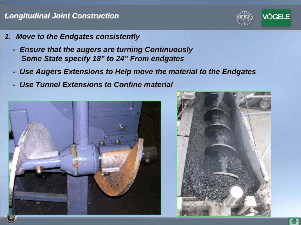
1.1. Move to the Endgates consistentlyMove to the Endgates consistently
-- Ensure that the augers are turning ContinuouslyEnsure that the augers are turning ContinuouslySome State specify 18Some State specify 18”” to 24to 24”” From endgates From endgates
-- Use Augers Extensions to Help move the material to the EndgateUse Augers Extensions to Help move the material to the Endgatess
-- Use Tunnel Extensions to Confine Use Tunnel Extensions to Confine materialmaterial
Longitudinal Joint ConstructionLongitudinal Joint Construction
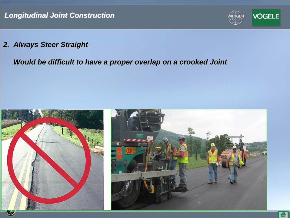
2. Always Steer Straight2. Always Steer Straight
Would be difficult to have a proper overlap on a crooked JoWould be difficult to have a proper overlap on a crooked Jointint
Longitudinal Joint ConstructionLongitudinal Joint Construction
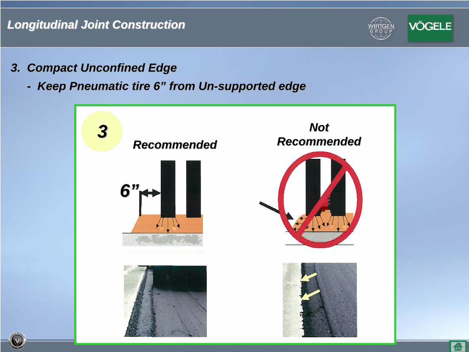
33
3. Compact Unconfined Edge3. Compact Unconfined Edge-- Keep Pneumatic tire 6Keep Pneumatic tire 6”” from Unfrom Un--supported edgesupported edge
66””
RecommendedRecommendedNotNot
RecommendedRecommended
Longitudinal Joint ConstructionLongitudinal Joint Construction
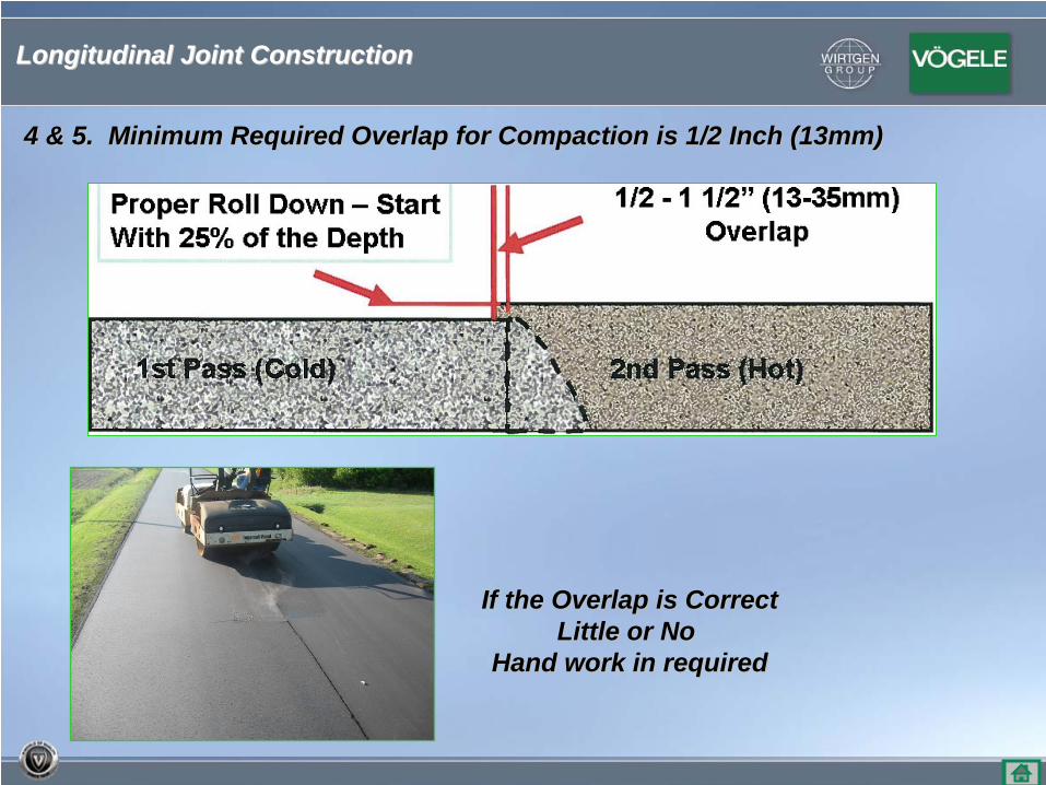
4 & 5. Minimum Required Overlap for Compaction is 1/2 Inch (13m4 & 5. Minimum Required Overlap for Compaction is 1/2 Inch (13mm)m)
If the Overlap is CorrectIf the Overlap is CorrectLittle or No Little or No
Hand work in requiredHand work in required
Longitudinal Joint ConstructionLongitudinal Joint Construction
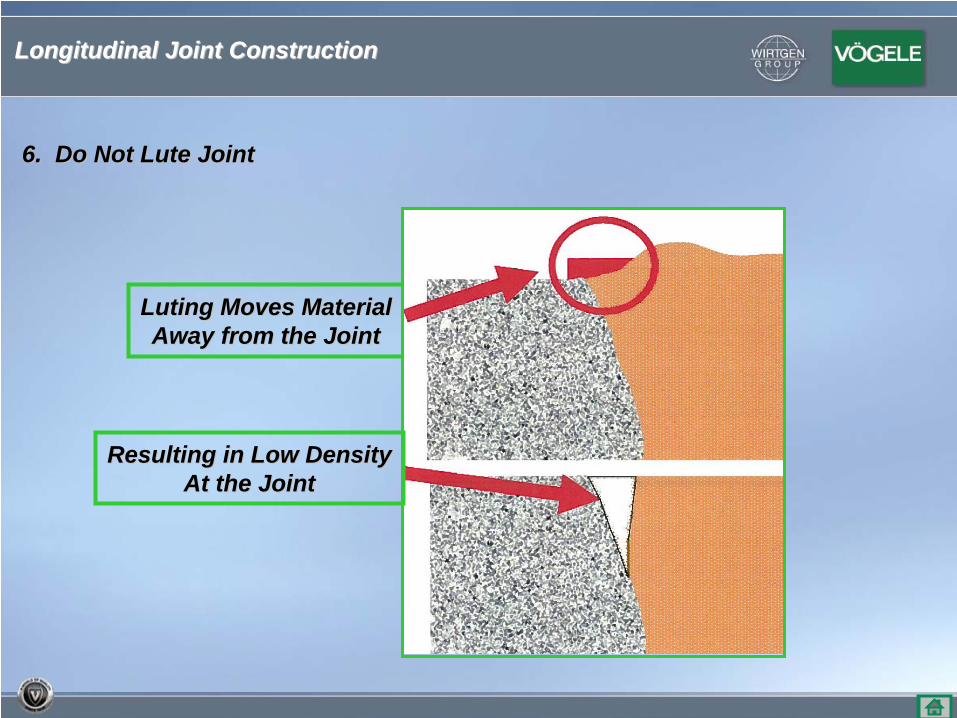
6. Do Not Lute Joint6. Do Not Lute Joint
Luting Moves MaterialLuting Moves MaterialAway from the JointAway from the Joint
Resulting in Low DensityResulting in Low DensityAt the JointAt the Joint
Longitudinal Joint ConstructionLongitudinal Joint Construction
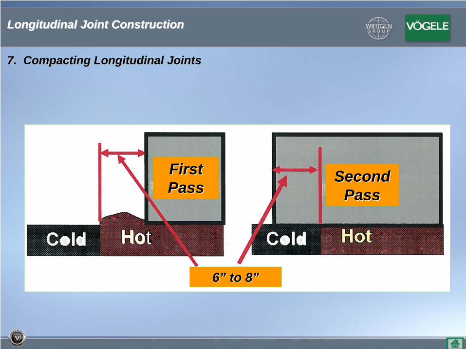
First First PassPass
66”” to 8to 8””
Second Second PassPass
7. Compacting Longitudinal Joints7. Compacting Longitudinal Joints
Hot
Longitudinal Joint ConstructionLongitudinal Joint Construction
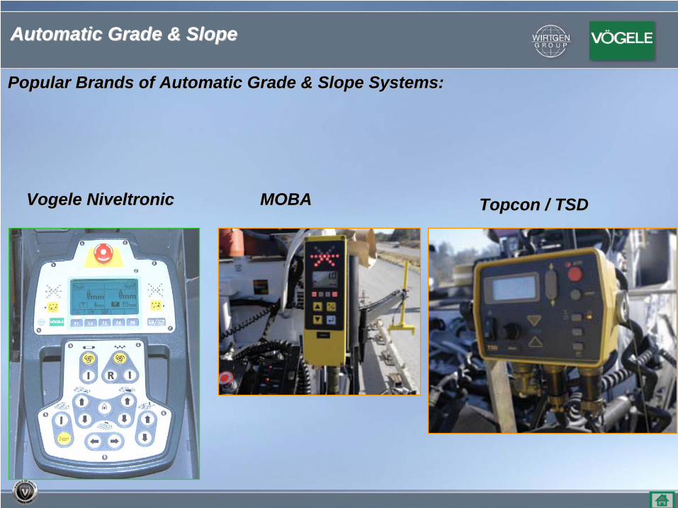
Popular Brands of Automatic Grade & Slope Systems:Popular Brands of Automatic Grade & Slope Systems:
Vogele NiveltronicVogele Niveltronic MOBAMOBA Topcon / TSDTopcon / TSD
Automatic Grade & SlopeAutomatic Grade & Slope
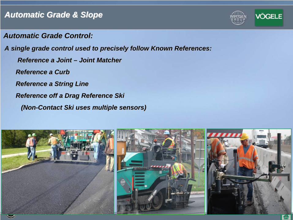
Automatic Grade Control:Automatic Grade Control:
A single grade control used to precisely follow Known ReferencesA single grade control used to precisely follow Known References::
Reference a Joint Reference a Joint –– Joint MatcherJoint Matcher
Reference a CurbReference a Curb
Reference a String LineReference a String Line
Reference off a Drag Reference SkiReference off a Drag Reference Ski
(Non(Non--Contact Ski uses multiple sensors)Contact Ski uses multiple sensors)
Automatic Grade & SlopeAutomatic Grade & Slope
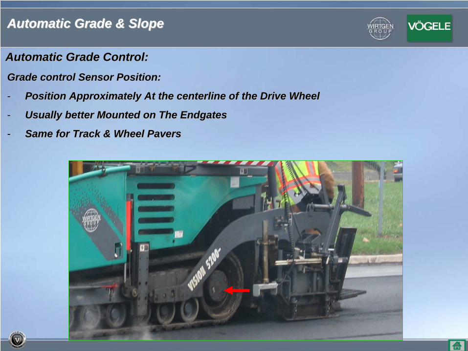
Automatic Grade Control:Automatic Grade Control:
Grade control Sensor Position:Grade control Sensor Position:
-- Position Approximately At the centerline of the Drive WheelPosition Approximately At the centerline of the Drive Wheel
-- Usually better Mounted on The EndgatesUsually better Mounted on The Endgates
-- Same for Track & Wheel PaversSame for Track & Wheel Pavers
Automatic Grade & SlopeAutomatic Grade & Slope
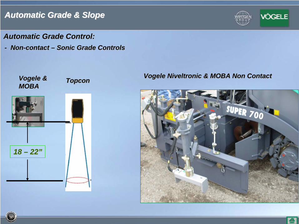
-- NonNon--contact contact –– Sonic Grade ControlsSonic Grade Controls
Vogele Niveltronic & MOBA Non ContactVogele Niveltronic & MOBA Non ContactVogele &Vogele &MOBAMOBA
TopconTopcon
18 18 –– 2222””
Automatic Grade Control:Automatic Grade Control:
Automatic Grade & SlopeAutomatic Grade & Slope
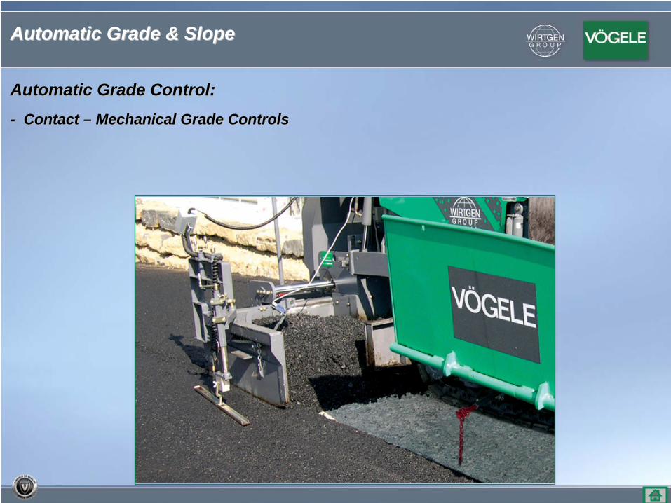
Automatic Grade Control:Automatic Grade Control:
-- Contact Contact –– Mechanical Grade ControlsMechanical Grade Controls
Automatic Grade & SlopeAutomatic Grade & Slope
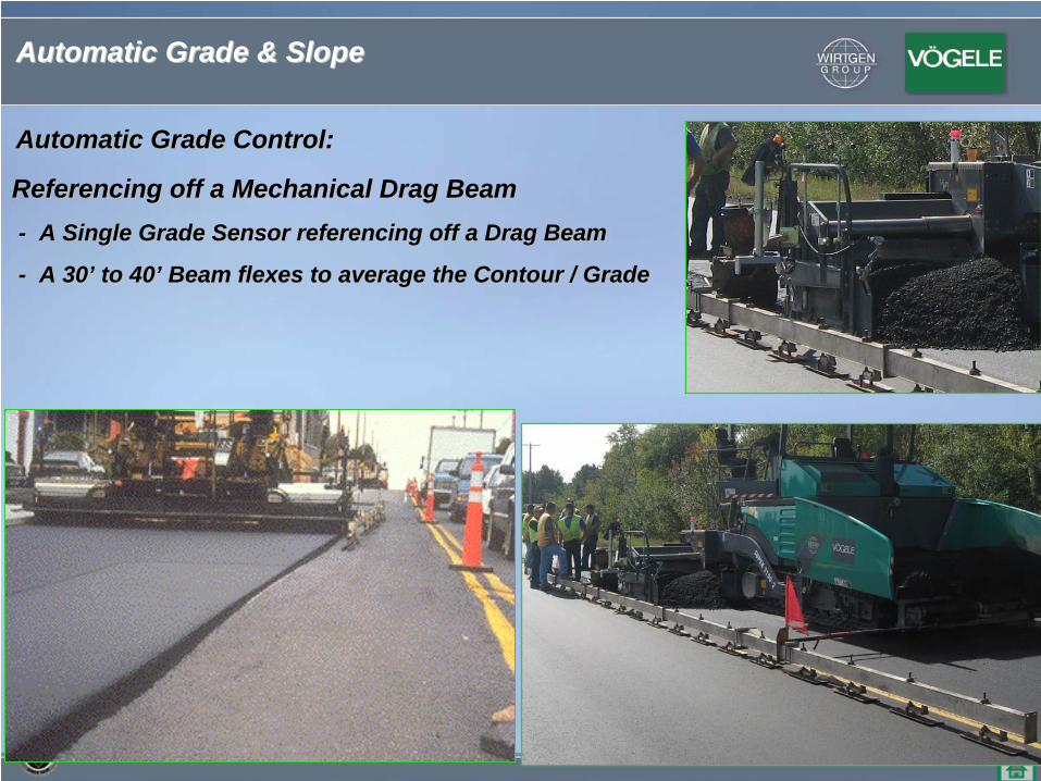
Referencing off a Mechanical Drag BeamReferencing off a Mechanical Drag Beam-- A Single Grade Sensor referencing off a Drag BeamA Single Grade Sensor referencing off a Drag Beam
-- A 30A 30’’ to 40to 40’’ Beam flexes to average the Contour / GradeBeam flexes to average the Contour / Grade
Automatic Grade Control:Automatic Grade Control:
Automatic Grade & SlopeAutomatic Grade & Slope
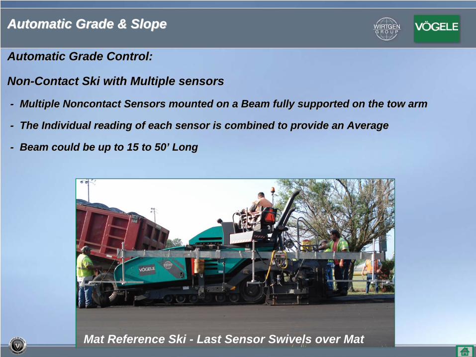
NonNon--Contact Ski with Multiple sensorsContact Ski with Multiple sensors
-- Multiple Noncontact Sensors mounted on a Beam fully supported Multiple Noncontact Sensors mounted on a Beam fully supported on the tow armon the tow arm
-- The Individual reading of each sensor is combined to provide aThe Individual reading of each sensor is combined to provide an Averagen Average
-- Beam could be up to 15 to 50Beam could be up to 15 to 50’’ Long Long
Mat Reference Ski - Last Sensor Swivels over Mat
Automatic Grade Control:Automatic Grade Control:
Automatic Grade & SlopeAutomatic Grade & Slope
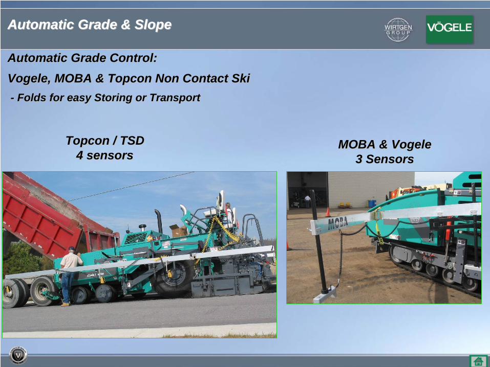
Vogele, MOBA & Topcon Non Contact SkiVogele, MOBA & Topcon Non Contact Ski-- Folds for easy Storing or TransportFolds for easy Storing or Transport
Topcon / TSDTopcon / TSD4 sensors4 sensors
MOBA & VogeleMOBA & Vogele3 Sensors3 Sensors
Automatic Grade Control:Automatic Grade Control:
Automatic Grade & SlopeAutomatic Grade & Slope
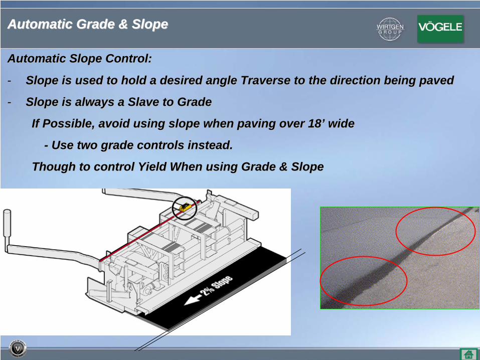
Automatic Slope Control:Automatic Slope Control:
-- Slope is used to hold a desired angle Traverse to the direction Slope is used to hold a desired angle Traverse to the direction being pavedbeing paved
-- Slope is always a Slave to GradeSlope is always a Slave to Grade
If Possible, avoid using slope when paving over 18If Possible, avoid using slope when paving over 18’’ widewide
-- Use two grade controls instead.Use two grade controls instead.
Though to control Yield When using Grade & SlopeThough to control Yield When using Grade & Slope
Automatic Grade & SlopeAutomatic Grade & Slope
MaintenanceMaintenance
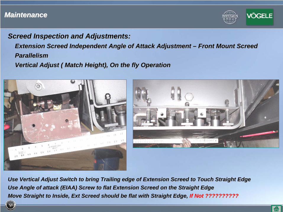
Screed Inspection and Adjustments:Screed Inspection and Adjustments:Extension Screed Independent Angle of Attack Adjustment Extension Screed Independent Angle of Attack Adjustment –– Front Mount ScreedFront Mount ScreedParallelismParallelismVertical Adjust ( Match Height), On the fly OperationVertical Adjust ( Match Height), On the fly Operation
Use Vertical Adjust Switch to bring Trailing edge of Extension SUse Vertical Adjust Switch to bring Trailing edge of Extension Screed to Touch Straight Edgecreed to Touch Straight EdgeUse Angle of attack (EIAA) Screw to flat Extension Screed on theUse Angle of attack (EIAA) Screw to flat Extension Screed on the Straight EdgeStraight EdgeMove Straight to Inside, Ext Screed should be flat with StraightMove Straight to Inside, Ext Screed should be flat with Straight Edge, Edge, If Not ??????????If Not ??????????
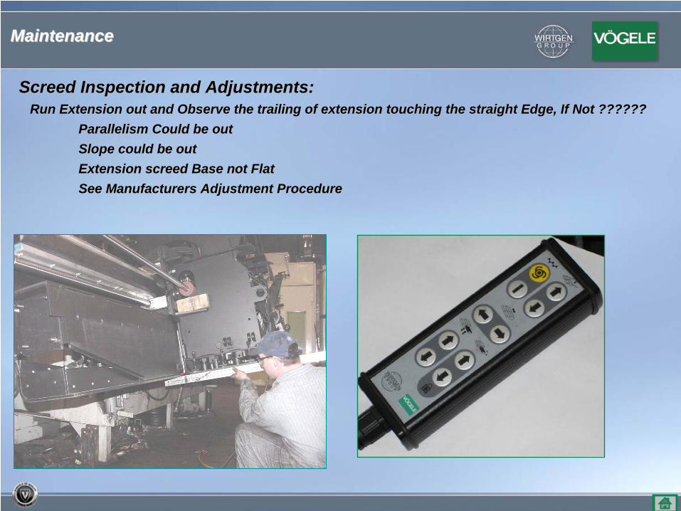
Screed Inspection and Adjustments:Screed Inspection and Adjustments:Run Extension out and Observe the trailing of extension touchRun Extension out and Observe the trailing of extension touching the straight Edge, If Not ??????ing the straight Edge, If Not ??????
Parallelism Could be outParallelism Could be outSlope could be outSlope could be outExtension screed Base not Flat Extension screed Base not Flat See Manufacturers Adjustment ProcedureSee Manufacturers Adjustment Procedure
MaintenanceMaintenance
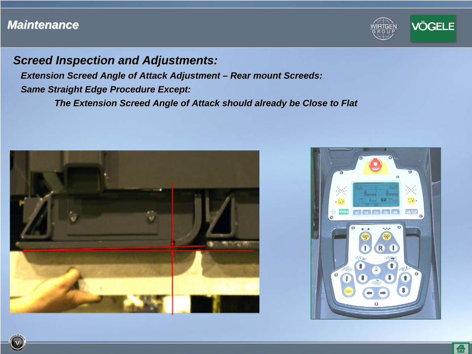
Screed Inspection and Adjustments:Screed Inspection and Adjustments:Extension Screed Angle of Attack Adjustment Extension Screed Angle of Attack Adjustment –– Rear mount Screeds:Rear mount Screeds:Same Straight Edge Procedure Except: Same Straight Edge Procedure Except:
The Extension Screed Angle of Attack should already be Close to The Extension Screed Angle of Attack should already be Close to FlatFlat
MaintenanceMaintenance
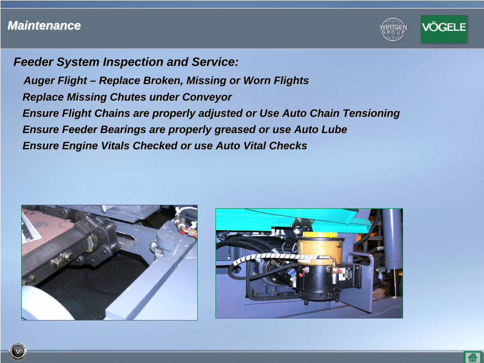
Feeder System Inspection and Service:Feeder System Inspection and Service:Auger Flight Auger Flight –– Replace Broken, Missing or Worn FlightsReplace Broken, Missing or Worn FlightsReplace Missing Chutes under ConveyorReplace Missing Chutes under ConveyorEnsure Flight Chains are properly adjusted or Use Auto Chain Ensure Flight Chains are properly adjusted or Use Auto Chain TensioningTensioningEnsure Feeder Bearings are properly greased or use Auto LubeEnsure Feeder Bearings are properly greased or use Auto LubeEnsure Engine Vitals Checked or use Auto Vital ChecksEnsure Engine Vitals Checked or use Auto Vital Checks
MaintenanceMaintenance

QuestionsQuestions
Thank YouThank You