Embed Size (px)
Citation preview
Agent Models for Concurrent Software Systems
Lawrence Cabac, Till Dörges, Michael Duvigneau, Daniel Moldt,Christine Reese, Matthias Wester-Ebbinghaus
University of Hamburg, Department of Computer Science,Vogt-Kölln-Str. 30, D-22527 Hamburg
http://www.informatik.uni-hamburg.de/TGI
Abstract In this work we present modeling techniques for the devel-opment of multi-agent applications within the reference architecture formulti-agent system Mulan. Our approach can be characterized as modeldriven development by using models in all stages and levels of abstrac-tion regarding design, implementation and documentation. Both, stan-dard techniques from software development as well as customized onesare used to satisfy the needs of multi-agent system development. To il-lustrate the techniques and models within this paper we use diagramscreated during the development of an agent-based distributed WorkflowManagement System (WFMS).
Keywords: high-level Petri nets, nets-within-nets, reference nets, netcomponents, Renew, modeling, agents, multi-agent systems, Paose
1 Introduction
The agent metaphor is highly abstract and it is necessary to develop software en-gineering techniques and methodologies that particularly fit the agent-orientedparadigm. They must capture the flexibility and autonomy of an agent’s problem-solving capabilities, the richness of agent interactions and the (social) organiza-tional structure of a multi-agent system as a whole.
Many agent-oriented software development methodologies have been broughtforward over the past decade, many of them already in a mature state. Here, wepresent our contribution to this rapidly evolving field of research by describingagent models and their usage during the development of multi-agent systemswith Mulan (Multi-Agent Nets [7]). As a matter of course there exist manyanalogies to related agent-oriented development techniques and methodologieslike Gaia [15], MaSE [4] or Prometheus [11]. This concerns development methodsand abstractions like use cases, system structure (organization) diagrams, rolemodels, interaction diagrams and interaction protocols as well as more fine-grained models of agents’ internal events, data structures and decision makingcapabilities.
Our approach Paose (Petri net-based AOSE) facilitates the metaphor ofmulti-agent systems in a formally precise and coherent way throughout all as-pects of software development as well as a concurrency-aware (Petri net-based)modeling and programming language. The metaphor of multi-agent systems is
R. Bergmann, G. Lindemann (Eds.): Multiagent System Technologies, LNAI 5244, pp. 37–48, 2008.c© Springer-Verlag Berlin Heidelberg 2008
38 Cabac, Dörges, Duvigneau, Moldt, Reese, Wester-Ebbinghaus
formalized by the Mulan reference architecture, which is modeled using refer-ence nets. We integrate several ideas from the methodologies mentioned aboveas well as concepts from conventional modeling techniques (UML). The result ofthose efforts is a development methodology that continuously integrates our phi-losophy of Petri net-based and model-driven software engineering in the contextof multi-agent systems.
This paper focuses on the set of modeling techniques used within the Paose
approach. Other aspects have already been presented, for example the multi-
agent system as a guiding metaphor for development processes in [1]. In Section 2we introduce the basic conceptual features of multi-agent application develop-ment with Mulan. The particular techniques, models and tools are presentedin Section 3.
2 Concepts of Application Development with Mulan
Reference nets1 and thus also Mulan run in the virtual machine provided byRenew [9], which also includes an editor and runtime support for several kindsof Petri nets. Since reference nets may carry complex Java-instructions as in-scriptions and thereby offer the possibility of Petri net-based programming, theMulan models have been extended to a fully elaborated and running softwarearchitecture, the FIPA2-compliant re-implementation Capa [5].
Reference nets can be regarded as a concurrency extension to Java, whichallows for easy implementation of concurrent systems in regard to modeling(implementation) and synchronization aspects. Those – often tedious – aspectsof implementation regarding concurrency are handled by the formalism as wellas by the underlying virtual machine. In this aspect lies the advantage of ourapproach. We rely on a formal background, which is at the same time tightlycoupled with the programming environment Java. Mulan can be regarded asa reference architecture for concurrent systems providing a highly structuredapproach using the multi-agent system metaphor.
We describe the internal components of the Mulan agent followed by aninvestigation of the interrelations between them, which results in the organiza-tional structure of the system. For the details of further aspects of the Mulan
architecture we refer to Rölke et. al. [7].
2.1 The Mulan Agent
The reference net-based multi-agent system architecture Mulan (Multi AgentNets) structures a multi-agent system in four layers, namely infrastructure, plat-
form, agent and protocol [7,12]. Figure 1 shows a schematic net model of a
1 Reference nets [8] are high-level Petri nets comparable to colored Petri nets. In addi-tion they implement the nets-within-nets paradigm where tokens are active elements(token refinement). Reference semantics is applied, so tokens are references to netinstances. Synchronous channels allow for communication between net instances.
2 Foundation for Intelligent Physical Agents http://www.fipa.org.
Agent Models for Concurrent Software Systems 39
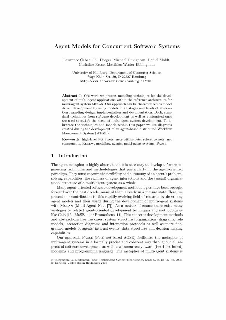
Figure 1. Agent net
Mulan agent. Several parts of the operational model, such as inscriptions, syn-chronous channels and initialization, are omitted for clearness. Instead, descrip-tive names have been given to the net elements representing synchronous chan-nels or place contents. The model stresses that the agent is a communicatingagent being able to receive and send messages. The labeled places store refer-ences to net instances that provide or refine the main functionality of the agent.These are the Factory, the Knowledge base, the Decision components, and theProtocols. Protocol and decision component nets comprise parts of the domain-specific agent behavior, the two corresponding places in the agent net may con-tain numerous net instances (compare nets-within-nets [14]).
The factory produces net instances from net patterns of protocols and de-cision components. It realizes reactive and proactive behavior by examining in-coming messages and the agent’s knowledge.
The knowledge base offers database functionality including atomic query, cre-ate, remove and modify operations to other subnets of the agent. It is used tostore persistent information to be shared by protocol nets and decision compo-nents, for example the agent’s representation of the environment. The knowledgebase also stores the agent’s configuration. It holds information about providedand required services, and a mapping of incoming messages to protocol nets.
Protocol nets implement domain-specific agent behavior. Each protocol nettemplate models the participation of an agent role in a multi-agent interactionprotocol. Instantiated protocol nets reside on the place Protocols of the agent,handle the processing of received messages and may generate outgoing messages.
40 Cabac, Dörges, Duvigneau, Moldt, Reese, Wester-Ebbinghaus
Protocol net instances are the manifestations of the agent’s involvement in an in-teraction with one or more other agents. They can access the knowledge base andexchange information with decision components through the exchange channel.
Decision components implement, like protocol nets, domain-specific agentbehavior. A decision component net instance can be queried by protocol net in-stances to add flexibility to the static, workflow-like character of protocol nets.Decision components can also initiate proactive agent behavior by requestingthe factory to instantiate protocol nets. Thus an AI-like planning componentcan be attached to an agent as a decision component or the functionality can beimplemented directly as reference nets. Decision components may also encapsu-late external tools or legacy code as well as a graphical user interface wherebythe external feedback is transformed into proactive agent behavior.
2.2 Organizational Structure
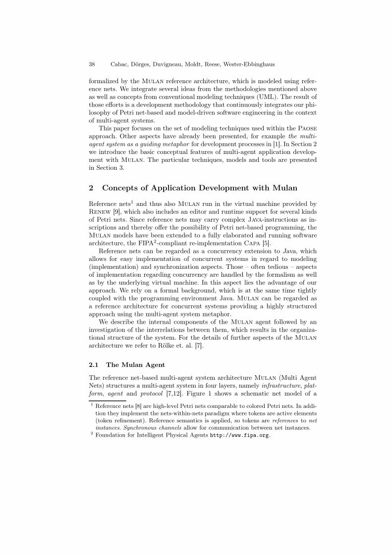
In a multi-agent application the organizational structure has to be defined, suchthat responsibilities for all aspects of the system are specified. The general per-spectives in the area of a multi-agent systems are the structure, the interactions,and the terminology. These perspectives are orthogonal with connecting pointsat some intersections (compare Figure 2).
The structure of a multi-agent system is given by the agents, their roles,knowledge bases and decision components. The behavior of a multi-agent systemis given by the interactions of the agents, their communicative acts and theinternal actions related to the interactions. The terminology of a multi-agentsystem is given as a domain-specific ontology definition that enables agents andinteractions to refer to the same objects, actions and facts. Without a commonontology successful interactions are impossible.
Figure 2. Two dimensional matrix showing perspectives (behavior, structure).
A schematic two dimensional matrix is depicted in Figure 2 showing theindependence and interconnection of agents and interactions. Neither is thereany direct relationship between any pair of agents, nor between any pair of in-teractions. Thus these architectural elements are independent and depicted inparallel to each other. Agents and interactions are shown as orthogonal because
Agent Models for Concurrent Software Systems 41
each agent is involved in some interactions. The general case for any two struc-tural and/or behavioral elements is independence, but interconnections exist.Coupled agents and interactions are marked by circles in the figure.
The terminology defined as ontology is the third dimension of perspectives(omitted in the diagram). It is orthogonal to the other two, but it tends to havemany interconnecting points because each interaction and each agent uses partsof the ontology definition to fulfill its purpose.
Since the three perspectives are orthogonal to each other and independentwithin the perspective, it is easily possible to divide the tasks of design andimplementation into independent parts. This means that different interactionscan be developed by independent sub-teams and different agents can be designedby other independent sub-teams. Between agent teams and interaction teams,coordination is needed for the crucial parts only (circles in the diagram).
These three perspectives enable us to develop the parts of the system inde-pendently and concurrently – thus also distributedly – as long as there is enoughcoordination / synchronization between intersecting groups.
3 Techniques, Models and Development Tools
In this section we describe the techniques applied during the various stagesof multi-agent application development with Mulan. An agent-based Work-flow Management System serves as an example application to provide real-worldmodels. However, since the WFMS is not the objective here, we will not go intodetail of its design.
We present the applied techniques and resulting models starting with thecoarse design giving an overview over the system, continuing with the definitionof the structure of the multi-agent application, the ontology and the behavior ofthe agents.
3.1 Coarse Design
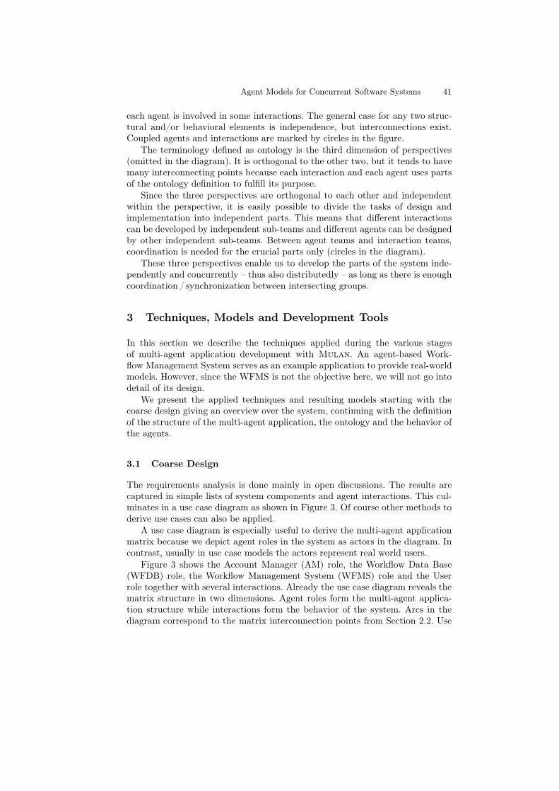
The requirements analysis is done mainly in open discussions. The results arecaptured in simple lists of system components and agent interactions. This cul-minates in a use case diagram as shown in Figure 3. Of course other methods toderive use cases can also be applied.
A use case diagram is especially useful to derive the multi-agent applicationmatrix because we depict agent roles in the system as actors in the diagram. Incontrast, usually in use case models the actors represent real world users.
Figure 3 shows the Account Manager (AM) role, the Workflow Data Base(WFDB) role, the Workflow Management System (WFMS) role and the Userrole together with several interactions. Already the use case diagram reveals thematrix structure in two dimensions. Agent roles form the multi-agent applica-tion structure while interactions form the behavior of the system. Arcs in thediagram correspond to the matrix interconnection points from Section 2.2. Use
42 Cabac, Dörges, Duvigneau, Moldt, Reese, Wester-Ebbinghaus
User
WFMS
AM
login/logout
init Workflow
offer Workitem List
request Workitem
cancel/confirm Activity
edit Workflow
WFDB
show State
authenticate
Use Cases in WFMS
@authors group discussion participants@date Nov 17, 2006
"/" in use casesand actor namesrefer to multiple use cases, actorsresp.
Almost all interactions thathandle workitems have to pass authenticaten.For diagram conciseness thesedependencies have been omitted.
Figure 3. Fragment of a use case diagram showing the system’s coarse design.
case diagrams are drawn directly in Renew. The use case plugin provides thefunctionality by adding a palette of drawing tools to the editor.
The use case plugin (UC-Plugin) integrates a generator feature, which gen-erates the complete folder structure of the application necessary for the imple-mentation of a multi-agent application. This includes a standard source packagefolder structure, skeletons for all agent interactions, role diagram and ontologyfiles as well as configuration files and build / start skripts. The generator utilizesthe Velocity3 template engine.
3.2 Multi-Agent Application Structure
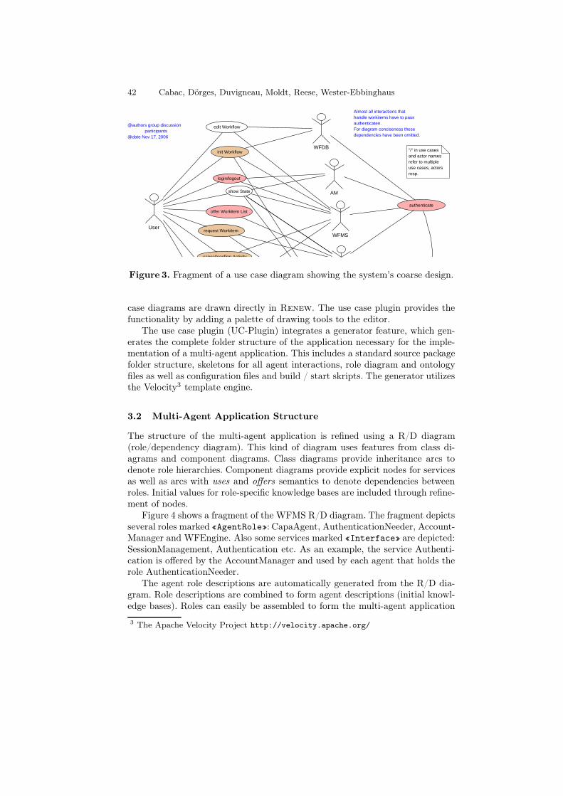
The structure of the multi-agent application is refined using a R/D diagram(role/dependency diagram). This kind of diagram uses features from class di-agrams and component diagrams. Class diagrams provide inheritance arcs todenote role hierarchies. Component diagrams provide explicit nodes for servicesas well as arcs with uses and offers semantics to denote dependencies betweenroles. Initial values for role-specific knowledge bases are included through refine-ment of nodes.
Figure 4 shows a fragment of the WFMS R/D diagram. The fragment depictsseveral roles marked «AgentRole»: CapaAgent, AuthenticationNeeder, Account-Manager and WFEngine. Also some services marked «Interface» are depicted:SessionManagement, Authentication etc. As an example, the service Authenti-cation is offered by the AccountManager and used by each agent that holds therole AuthenticationNeeder.
The agent role descriptions are automatically generated from the R/D dia-gram. Role descriptions are combined to form agent descriptions (initial knowl-edge bases). Roles can easily be assembled to form the multi-agent application
3 The Apache Velocity Project http://velocity.apache.org/
Agent Models for Concurrent Software Systems 43
Figure 4. Fragment of a R/D diagram (agents, roles, services).
using the graphical user interface. The multi-agent application is started eitherfrom within the tool, by a startup script or by a Petri net.
3.3 Terminology
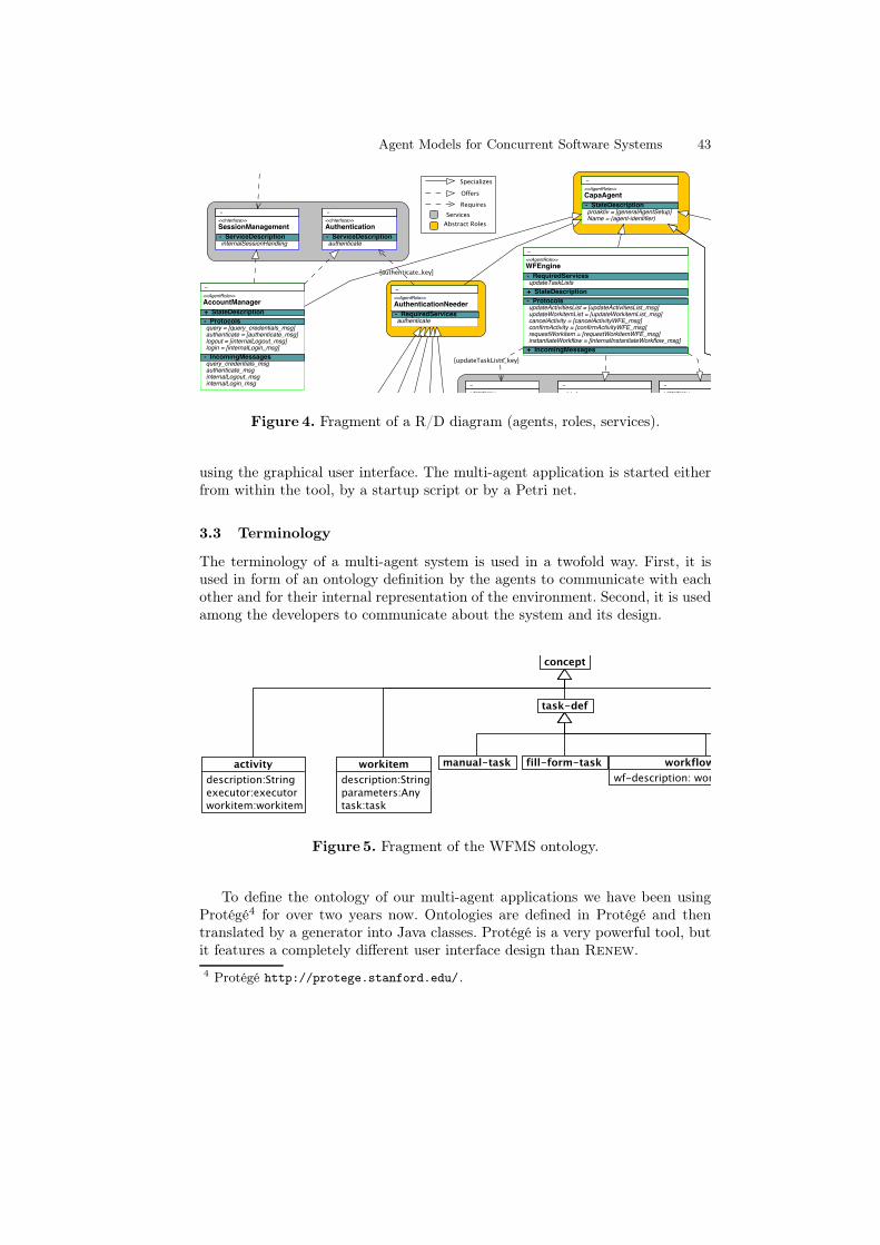
The terminology of a multi-agent system is used in a twofold way. First, it isused in form of an ontology definition by the agents to communicate with eachother and for their internal representation of the environment. Second, it is usedamong the developers to communicate about the system and its design.
Figure 5. Fragment of the WFMS ontology.
To define the ontology of our multi-agent applications we have been usingProtégé4 for over two years now. Ontologies are defined in Protégé and thentranslated by a generator into Java classes. Protégé is a very powerful tool, butit features a completely different user interface design than Renew.
4 Protégé http://protege.stanford.edu/.

44 Cabac, Dörges, Duvigneau, Moldt, Reese, Wester-Ebbinghaus
The Renew feature structure plugin allows to explicitly model the ontologyas a concept diagram as shown in Figure 5. These are class diagrams restrictedto inheritance and association. The concept diagrams can easily be understoodby all sub-teams to capture the context of the concepts in use.
Up to now, the translation of models from the feature structure concepts toProtégé ontologies is a manual task. The Protégé model can then be used togenerate the Java ontology classes. However, we have also developed a proto-typical implementation of an ontology classes generator (directly) from conceptdiagrams. We are also working on transformations from and to Protégé models.
3.4 Knowledge and Decisions
While the agent’s interactive behavior is defined in the interaction protocols (seenext section), the facts about its environment are located in the agent’s knowl-edge base. The initial knowledge of the agent is defined in its initial knowledgebase file, constructed by joining information from the role definitions, whichhave been defined in the R/D diagram (introduced in Section 3.2). This XMLdocument that can also be customized apart from the R/D diagram is parsed tobuild the initial knowledge of the agent during its initialization. Alternatively, atext file in the style of properties files suffices for the same purpose.
START
channelname
s
:newExchange(s, workitem, id);
[id,workitem]
>> id
[id,success]
proxy [request workitemfrom proxy]
id id
requestedworkitem
proxy:request(workitem,success)
requestedworkitems
[id,workitem]
>
>
>
id
id
id
id
id
id
successinformation
refuse
accept
[id,success]
[id,success]success
information
guard (success==true)
action sucs=new Success()
channelname
s
s
:exchange(s,sucs,id)
guard (success==false)action fail=new Failure("not")
:exchange(s,fail,id)
[report whethersuccessful
or not]
Request Workitem
proxy
Figure 6. Fragment of a decision component net: RequestWorkitemHandling
Decision components (DC) are constructed as reference nets. There exists ageneralized form of a DC providing GUI interface connection. Also net compo-nents [2] for the development of DCs are provided.
Figure 6 shows a fragment of the DC net handling the request of a user for aworkitem in the workitem dispatcher agent. The net holds the proxy net whichimplements the interface to the workflow engine. A request starts at the left ofthe image and is handed over to the proxy, which holds a list of available workitems for the given user. The result of the request is handed back to the DC netand passed (via the exchange channel) on to the requester, a protocol net, whichin turn sends an appropriate message to the requesting agent.
Agent Models for Concurrent Software Systems 45
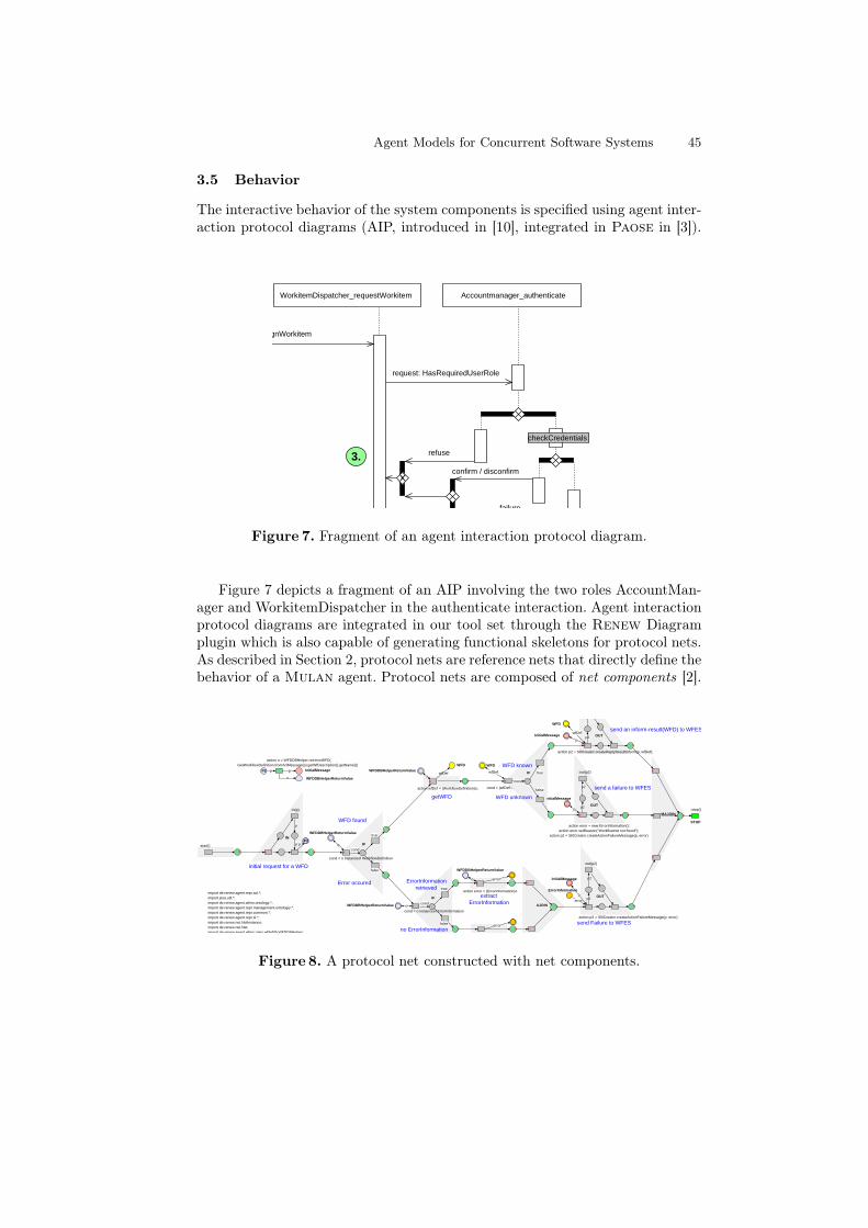
3.5 Behavior
The interactive behavior of the system components is specified using agent inter-action protocol diagrams (AIP, introduced in [10], integrated in Paose in [3]).
refuse
failure
3.
checkCredentials
request: HasRequiredUserRole
confirm / disconfirm
Accountmanager_authenticateWorkitemDispatcher_requestWorkitem
request: assignWorkitem
Figure 7. Fragment of an agent interaction protocol diagram.
Figure 7 depicts a fragment of an AIP involving the two roles AccountMan-ager and WorkitemDispatcher in the authenticate interaction. Agent interactionprotocol diagrams are integrated in our tool set through the Renew Diagramplugin which is also capable of generating functional skeletons for protocol nets.As described in Section 2, protocol nets are reference nets that directly define thebehavior of a Mulan agent. Protocol nets are composed of net components [2].
>
:start()
import de.renew.agent.repr.acl.*;import java.util.*;import de.renew.agent.wfms.ontology.*;import de.renew.agent.repr.management.ontologiy.*;import de.renew.agent.repr.common.*;import de.renew.agent.repr.sl.*;import de.renew.net.NetInstance;import de.renew.net.Net;import de.renew.agent.wfms.roles.wfdefdb.WFDDBHelper;
P2p
>
:in(p)
p
>
p
IN
p pP2
p2
p2
>
OUT
:out(p2)
>
p2
p2
>
OUT
>
:stop()
STOP
>
InitialMessage
p
p
InitialMessage
action error = new ErrorInformation();action error.setReason("Workflownet not found");
action p2 = Sl0Creator.createActionFailureMessage(p, error)
initial request for a WFD
send an inform-result(WFD) to WFES
send a failure to WFES
WFD WFD
wfDefwfDef
WFD
wfDef
action p2 = Sl0Creator.createReplyResultInform(p, wfDef);
o
action o = WFDDBHelper.retrieveWFD(GetWorkflowDefinition.fromAclMessage(p).getWfDescription().getName())
WFDDBHelperReturnValue
o
WFD found
>
Error occured
>
IF
false
true
>
cond
>
>
>
>
MAJOIN
cond = o instanceof WorkflowDefinition
ErrorInformationretrieved
>
no ErrorInformation >
IF
false
true
>
cond
>>
extractErrorInformation
>>
>
>
AJOIN
>
>
:out(p2)
action p2 = Sl0Creator.createActionFailureMessage(p, error)
send Failure to WFES
OUT
p2
p2
>
>>
action wfDef = (WorkflowDefinition)o;
getWFD
o
WFDDBHelperReturnValue
WFDDBHelperReturnValue o
WFDDBHelperReturnValue
o
error
error
error
action error = (ErrorInformation)o
action error = new ErrorInformation();
pErrorInformation
InitialMessage
cond = o instanceof ErrorInformation
WFDDBHelperReturnValue
InitialMessage
>
>
cond = (wfDef!=null)false
trueIF
>
WFD known
WFD unknown
cond
Figure 8. A protocol net constructed with net components.
46 Cabac, Dörges, Duvigneau, Moldt, Reese, Wester-Ebbinghaus
Net components are also used for automatic generation of protocol net skeletonsfrom agent interaction protocol diagrams. The protocol nets are then refinedduring the implementation phase by adding inscriptions to the nets. Figure 8shows an example protocol net.5 Several decisions are made after receiving arequest message. Finally, the appropriate answer is sent back.
With the implementation of interactions as protocol nets, the internal pro-cesses as decision components and the knowledge bases through the descriptionof the role diagram, the whole multi-agent application is defined.
Additionally, all diagrams presented here serve as documentation elementsand are included in the API-documentation of the system (MulanDoc Plugin).
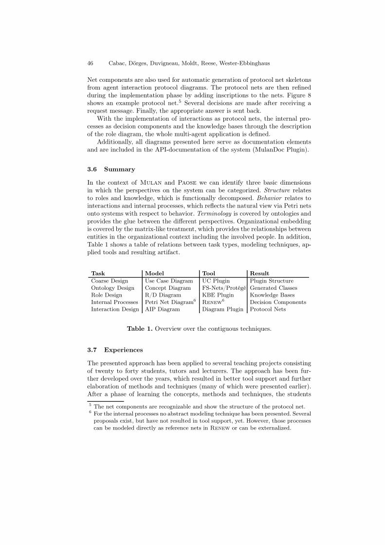
3.6 Summary
In the context of Mulan and Paose we can identify three basic dimensionsin which the perspectives on the system can be categorized. Structure relatesto roles and knowledge, which is functionally decomposed. Behavior relates tointeractions and internal processes, which reflects the natural view via Petri netsonto systems with respect to behavior. Terminology is covered by ontologies andprovides the glue between the different perspectives. Organizational embeddingis covered by the matrix-like treatment, which provides the relationships betweenentities in the organizational context including the involved people. In addition,Table 1 shows a table of relations between task types, modeling techniques, ap-plied tools and resulting artifact.
Task Model Tool Result
Coarse Design Use Case Diagram UC Plugin Plugin StructureOntology Design Concept Diagram FS-Nets/Protégé Generated ClassesRole Design R/D Diagram KBE Plugin Knowledge BasesInternal Processes Petri Net Diagram6
Renew6 Decision Components
Interaction Design AIP Diagram Diagram Plugin Protocol Nets
Table 1. Overview over the contiguous techniques.
3.7 Experiences
The presented approach has been applied to several teaching projects consistingof twenty to forty students, tutors and lecturers. The approach has been fur-ther developed over the years, which resulted in better tool support and furtherelaboration of methods and techniques (many of which were presented earlier).After a phase of learning the concepts, methods and techniques, the students
5 The net components are recognizable and show the structure of the protocol net.6 For the internal processes no abstract modeling technique has been presented. Several
proposals exist, but have not resulted in tool support, yet. However, those processescan be modeled directly as reference nets in Renew or can be externalized.
Agent Models for Concurrent Software Systems 47
were able to design and construct rather complex concurrent and distributedsoftware systems. For example, an agent-based workflow management system(compare with the diagrams of this paper) was developed using this approach.
The results of 5 weeks of teaching and 9 weeks of implementation includeabout 10 agent roles, more than 20 interactions and almost 70 concepts in theontology. The outcome is a running prototype of an distributed agent basedworkflow management system, where a user is represented by an agent andthe basic features are provided through a user GUI: Authentication, workflowinstantiation, offering of available tasks according to application roles and taskrules, accepting, cancellation and conclusion of tasks during the progress of aworkflow. Workflows themselves are specified with Petri nets using a special tasktransition which provides cancellation (compare [6]). Thus synchronization andconflict solving are provided by the inherent features of the Renew simulationengine. This example and our other previous projects show that Paose togetherwith the guiding metaphor of a multi-agent system of developers [1] enable us todevelop multi-agent applications with Mulan. The developed methods and thetool support have proven to be effective in supporting the development process.
4 Conclusion
In this paper we present the modeling techniques used within the Paose ap-proach to build agent models. The tools that are used during the developmentprocess support all tasks of development with modeling power, code genera-tion and deployment facilities. Still some of the tools have prototypical char-acter. Specifically, we have presented techniques to model structure, behaviorand terminology of concurrent software systems in a coherent way following themulti-agent paradigm. All techniques and tools own semantics built upon theunique, concurrency-oriented modeling and programming language of referencenets, either directly or by referring to the Mulan reference architecture.
The concurrency-awareness in development process and modeling techniquesdistinguishes our approach from most of the methodologies mentioned in theintroduction since they usually do not address true concurrency explicitly (com-pare [13]). The advantage of tight integration of abstract modeling techniqueswith the conceptual framework given through the formal model of Mulan isresponsible for the clearness and the effectivity of our approach.
For the future, we follow several directions to refine the approach. On thepractical side, we look into further developments, improvements and integrationof tools and techniques. On the conceptual side, we work on expanding the multi-agent-oriented approach to other aspects of the development process like projectorganization and agent-oriented tool support. Following these directions, we wantto achieve symmetrical structures in all three aspects of software development:the system, the development process and the project organization (compare [1]).
48 Cabac, Dörges, Duvigneau, Moldt, Reese, Wester-Ebbinghaus
References
1. Lawrence Cabac. Multi-agent system: A guiding metaphor for the organizationof software development projects. In Petta Paolo, editor, Proceedings of the FifthGerman Conference on Multiagent System Technologies, volume 4687 of LNCS,pages 1–12, Leipzig, Germany, 2007. Springer-Verlag.
2. Lawrence Cabac, Michael Duvigneau, and Heiko Rölke. Net components revisited.In Daniel Moldt, editor, Fourth International Workshop on Modelling of Objects,Components, and Agents. MOCA 2006, pages 87–102, 2006.
3. Lawrence Cabac, Daniel Moldt, and Heiko Rölke. A proposal for structuring Petrinet-based agent interaction protocols. In Wil van der Aalst and E. Best, editors,24th International Conference on Application and Theory of Petri Nets, Eind-hoven, Netherlands, volume 2679 of LNCS, pages 102–120. Springer-Verlag, 2003.
4. Scott DeLoach. Engineering organization-based multiagent systems. In SoftwareEngineering for Large-Scale Multi-Agent Systems (SELMAS), volume 3914 of Lec-ture Notes in Computer Science, pages 109–125. Springer Verlag, 2005.
5. M. Duvigneau, D. Moldt, and H. Rölke. Concurrent architecture for a multi-agentplatform. In Fausto Giunchiglia, James Odell, and Gerhard Weiß, editors, Proc.of AOSE 2002, volume 2585 of LNCS, Berlin, 2003. Springer Verlag.
6. Thomas Jacob, Olaf Kummer, Daniel Moldt, and Ulrich Ultes-Nitsche. Implemen-tation of workflow systems using reference nets – security and operability aspects.In Kurt Jensen, editor, Fourth Workshop on Practical Use of Coloured Petri Nets.University of Aarhus, Department of Computer Science, August 2002.
7. Michael Köhler, Daniel Moldt, and Heiko Rölke. Modelling the structure andbehaviour of Petri net agents. In J.M. Colom and M. Koutny, editors, Proceedingsof the 22nd Conference on Application and Theory of Petri Nets 2001, volume 2075of LNCS, pages 224–241. Springer-Verlag, 2001.
8. Olaf Kummer. Introduction to Petri nets and reference nets. Sozionik Aktuell,1:1–9, 2001. ISSN 1617-2477.
9. Olaf Kummer, Frank Wienberg, and Michael Duvigneau. Renew – The ReferenceNet Workshop. http://www.renew.de, March 2007. Release 2.1.
10. James Odell, H. Van Dyke Parunak, and Bernhard Bauer. Extending UML foragents. In Gerd Wagner, Yves Lesperance, and Eric Yu, editors, Proc. of theAgent-Oriented Information Systems Workshop at the 17th National conference onArtificial Intelligence, pages 3–17, 2000.
11. Lin Padgham and Michael Winikoff. Prometheus: A pragmatic methodology forengineering intelligent agents. In Proceedings of the OOPSLA 2002 Workshop onAgent–Oriented Methodologies, pages 97–108, 2002.
12. Heiko Rölke. Modellierung von Agenten und Multiagentensystemen – Grundlagenund Anwendungen, volume 2 of Agent Technology – Theory and Applications. LogosVerlag, Berlin, 2004.
13. Onn Shehory and Arnon Sturm. Evaluation of modeling techniques for agent-basedsystems. In Agents, pages 624–631, 2001.
14. Rüdiger Valk. Petri nets as token objects - an introduction to elementary objectnets. In Jörg Desel and Manuel Silva, editors, 19th International Conference onApplication and Theory of Petri nets, Lisbon, Portugal, number 1420 in LNCS,pages 1–25, Berlin, Heidelberg, New York, 1998. Springer-Verlag.
15. Franco Zambonelli, Nicholas Jennings, and Michael Wooldridge. Developing multi-agent systems: The Gaia methodology. ACM Transactions on Software Engineeringand Methodology, 12(3):317–370, 2003.


![[JavaOne 2011] Models for Concurrent Programming](https://img.pdfslide.net/doc/110x75/5550f3bdb4c90501448b45c6/javaone-2011-models-for-concurrent-programming.jpg)