Embed Size (px)
Citation preview

Agile RUP for non-object-oriented projects
by Gary Evans
PresidentEvanetics, Inc.
The Unified Modeling Language (UML) and IBM Rational Unified Process,® or RUP,® are standard fixtures on most object-oriented projects today. UML is a notation for visually expressing object-oriented concepts; RUP is a process framework that uses the UML to express the content of its artifacts and tasks. But what do RUP and the UML offer that portion of our software community doing non-object oriented development? This article is my answer to that question. As we shall see, RUP and UML can be used quite effectively on software projects in COBOL, C, or even (the dreaded) assembler language.
RUP values and practices
RUP is not so much a defined process as it is a description of a process framework. Because it is a generic framework, it is large and complex. But putting aside its substantial footprint (more than 3,000 files in more than 200 folders), RUP incorporates a very simple vision based on six basic principles, or what IBM Rational calls software development best practices:
● Develop iteratively
● Manage requirements
● Use component architectures
● Model visually
● Continuously verify quality
Copyright Rational Software 2003 http://www.therationaledge.com/content/sep_03/m_rupagility_ge.jsp

● Manage change
These core principles characterize the "personality" of RUP. They dictate that an effective process should be:
● Iterative -- Do the same activities in small pieces, over and over.
● Incremental -- Plan to gain a bit more understanding of the problem, and add a bit more of the solution, at each iteration, building on what you did previously.
● Risk-focused -- Address risk early and often. Focus on the most architecturally significant properties of the system, including the highest risk areas, before developing the easy, "low hanging fruit" of the system.
● Controlled -- Always know where you are, where you are going, and how far you have yet to go.
● Use-case (i.e., requirements)-driven -- Establish the goal of the system by capturing all its requirements; and capture the operational requirements in use cases.
● Architecture-centric -- Emphasize architectural stability over software design details.
For software groups doing procedural development within the traditional "waterfall" process, adopting the six RUP principles can seem a daunting challenge. Why should an organization give up all the techniques they know for new practices they don't know? This is a crucial question, and I will come back to it later to offer an answer.
UML in the Key of C
A lot of readers will not be using COBOL on their projects. But many will be developing in C, so here's a quick outline on how to do the UML-to- language mapping for C.3
Class allocation. Allocate one class per file. This is à la Java, and it just makes the code easier to manage.
Global variables.
Agile development values and practices
RUP has an additional characteristic that is implicit in the properties listed above: It is a prescriptive process definition. By prescriptive, I mean it pre-scribes (literally, it's all written down for teams ahead of time) the tasks, workers, and artifacts that a project using RUP should follow. Now, being prescriptive is not an evil thing. For many organizations used to developing software via the Indiana Jones process ("I'm making it up as I go, kid"!), the checklist and tour guide that RUP offers can dramatically reduce a team's anxiety in transitioning to an actual, defined process. However, I have also worked with way too many organizations that, in deciding to use RUP, thought they had to use all of RUP on every size project. Ouch! The sheer mass of content in RUP is enough to sink any project that tries to cover all of it.
Over the past four years, a grass-roots reaction to
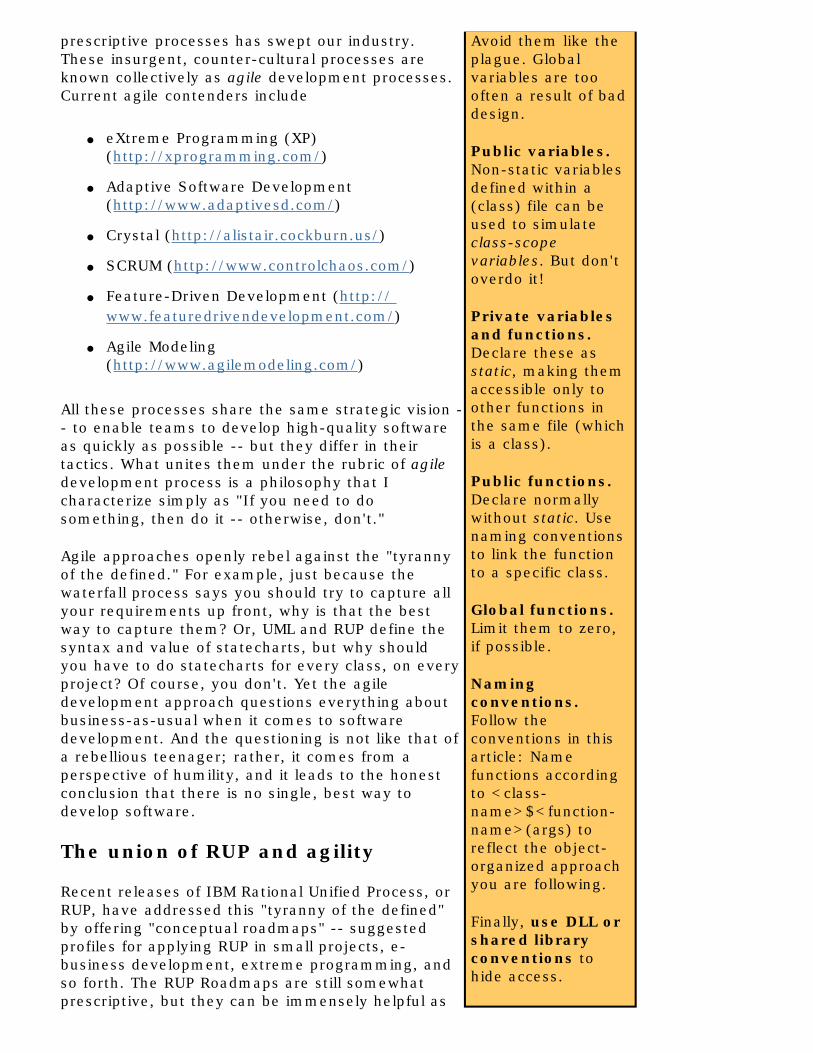
Avoid them like the plague. Global variables are too often a result of bad design.
Public variables. Non-static variables defined within a (class) file can be used to simulate class-scope variables. But don't overdo it!
Private variables and functions. Declare these as static, making them accessible only to other functions in the same file (which is a class).
Public functions. Declare normally without static. Use naming conventions to link the function to a specific class.
Global functions. Limit them to zero, if possible.
Naming conventions. Follow the conventions in this article: Name functions according to <class-name>$<function-name>(args) to reflect the object-organized approach you are following.
Finally, use DLL or shared library conventions to hide access.
prescriptive processes has swept our industry. These insurgent, counter-cultural processes are known collectively as agile development processes. Current agile contenders include
● eXtreme Programming (XP) (http://xprogramming.com/)
● Adaptive Software Development (http://www.adaptivesd.com/)
● Crystal (http://alistair.cockburn.us/)
● SCRUM (http://www.controlchaos.com/)
● Feature-Driven Development (http:// www.featuredrivendevelopment.com/)
● Agile Modeling (http://www.agilemodeling.com/)
All these processes share the same strategic vision -- to enable teams to develop high-quality software as quickly as possible -- but they differ in their tactics. What unites them under the rubric of agile development process is a philosophy that I characterize simply as "If you need to do something, then do it -- otherwise, don't."
Agile approaches openly rebel against the "tyranny of the defined." For example, just because the waterfall process says you should try to capture all your requirements up front, why is that the best way to capture them? Or, UML and RUP define the syntax and value of statecharts, but why should you have to do statecharts for every class, on every project? Of course, you don't. Yet the agile development approach questions everything about business-as-usual when it comes to software development. And the questioning is not like that of a rebellious teenager; rather, it comes from a perspective of humility, and it leads to the honest conclusion that there is no single, best way to develop software.
The union of RUP and agility
Recent releases of IBM Rational Unified Process, or RUP, have addressed this "tyranny of the defined" by offering "conceptual roadmaps" -- suggested profiles for applying RUP in small projects, e-business development, extreme programming, and so forth. The RUP Roadmaps are still somewhat prescriptive, but they can be immensely helpful as

a jumpstart for development teams working on projects that match these profiles.
With their inherent differences, is it conceivable that RUP and agile approaches could ever co-exist? Absolutely. IBM Rational has recently produced numerous papers on how to make RUP more agile. I also published a Rational Edge article about an agile approach to RUP that I use on all of my projects (see "A Simplified Approach to RUP" at http://www.therationaledge.com/content/jan_01/t_rup_ge.html).
Making RUP agile is not a violation of RUP philosophy; it simply requires that we make our own decisions about what we will use and do on our projects. If you approach RUP as a cafeteria menu rather than as a set of inscribed stone tablets, you will do fine.
A new perspective for non-OO developers
"Ok," you may say, "I have a cafeteria mentality, and I routinely question everything. How does this help me develop a COBOL application using RUP and UML? I don't have any objects in these languages." True enough, but you don't have customers, purchase orders, bills, or price quotes in your COBOL or C program, either. Yet these are concepts that everyone uses when talking about programs and business models. And your design thinking shows an intent to capture these concepts.
At this point in our discussion we must make some very important distinctions. We must discipline ourselves to think from qualitatively different perspectives, as Martin Fowler has expressed:1
● Conceptual Perspective: Represents the concepts in the domain of interest.
● Specification Perspective: Captures the interfaces of the software, not the implementation.
● Implementation Perspective: Captures the embodiment of the software, including internal implementation.
These distinct perspectives are crucial in our attempt to apply object-oriented techniques to non-object oriented development projects. When we are exploring our system-to-be from either a conceptual or specification perspective, the implementation language, algorithmic details, and platform constraints just don't matter yet. It is easy to look at UML as a notation system and subtly conclude that it is tied to an implementation language. But it isn't -- in fact, the power of UML is a direct consequence of its ability to help you assume a conceptual and a specification perspective on your system-to-be.
These facts are always true:
● The development language we choose is not the focus of our business.

● When we implement, we are always implementing some kind of conceptual or specification model.
● Developers think in terms of these conceptual models, regardless of what development language they ultimately use.
● UML lets us bring this conceptualization to the forefront of our thinking.
It should be evident that the pre-coding tasks in which requirements capture, analysis, and design occur all produce conceptual models as outputs, regardless of the implementation language. In the procedural world, these conceptual models would include data flow diagrams, flowcharts, logical data models, control flow diagrams, context diagrams, and so forth..
But conceptually, we can regard a COBOL billing system or a Call-record Tracking System as objects or components that:
● Have defined functionality.
● Are accessed according to specific interfaces.
● Should hide their implementation details.
● Have defined structure (the data they own and operate on).
The object-organized approach
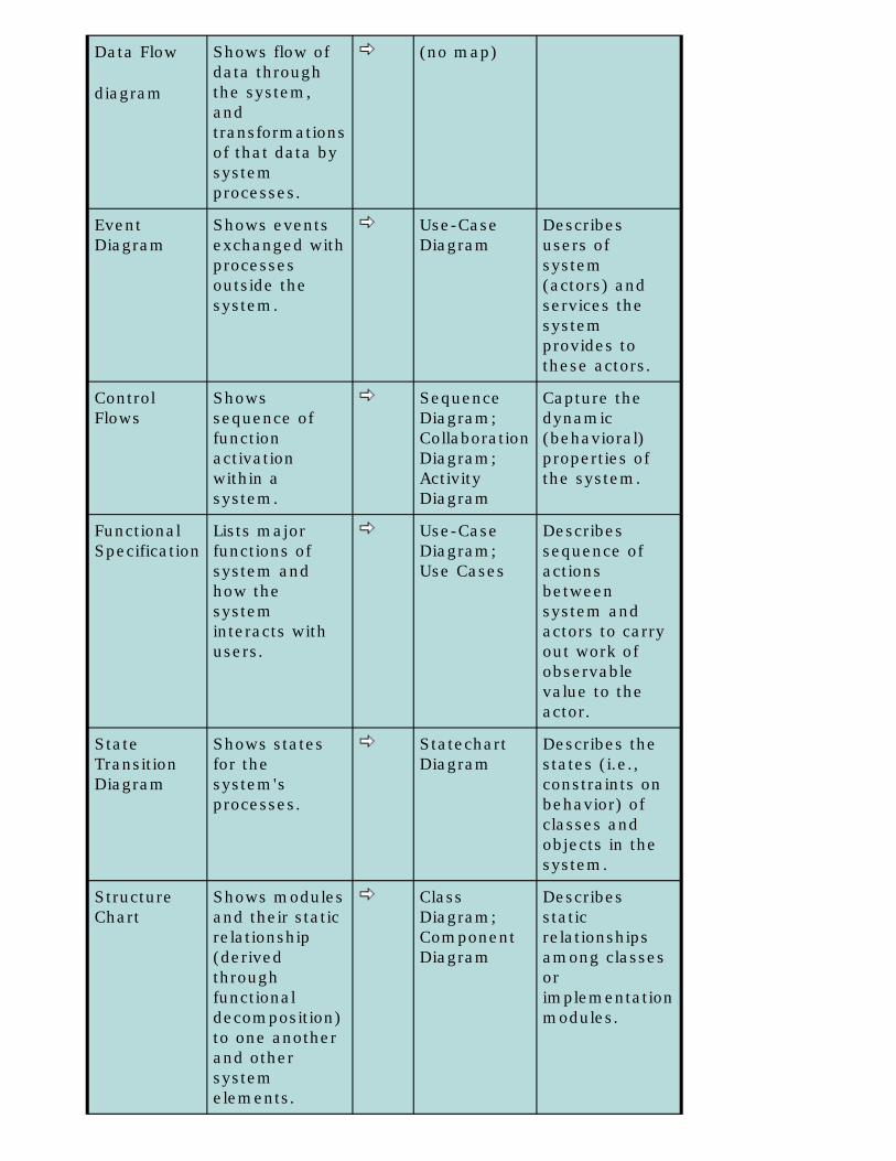
Even the notational gap between the procedural/structured world and the UML world is not really as large as we might first think. Table 1 shows how the traditional modeling elements of structured analysis/structured design map to the UML diagrams.
Table 1: Mapping structured artifacts to UML
Structured artifact
Description Maps to
UML artifact
Description
Context Diagram
Shows external data sources and sinks, and the data exchanged. (Highest level DFD)
(no map)
Data Flow
diagram
Shows flow of data through the system, and transformations of that data by system processes.
(no map)
Event Diagram
Shows events exchanged with processes outside the system.
Use-Case Diagram
Describes users of system (actors) and services the system provides to these actors.
Control Flows
Shows sequence of function activation within a system.
Sequence Diagram;Collaboration Diagram;Activity Diagram
Capture the dynamic (behavioral) properties of the system.
Functional Specification
Lists major functions of system and how the system interacts with users.
Use-Case Diagram; Use Cases
Describes sequence of actions between system and actors to carry out work of observable value to the actor.
State Transition Diagram
Shows states for the system's processes.
Statechart Diagram
Describes the states (i.e., constraints on behavior) of classes and objects in the system.
Structure Chart
Shows modules and their static relationship (derived through functional decomposition) to one another and other system elements.
Class Diagram;Component Diagram
Describes static relationships among classes or implementation modules.

Entity Relationship Diagrams
Logical data modeling diagrams to explore data relationships.
Class Diagram
Describes static relationships among classes.
System Diagram
Shows processes and their allocation to processors.
Deployment Diagram
Describes processes and their allocation to devices and processors.
We might dispute the exact extent of the mapping shown, but both sets of artifacts attempt to present a multi-dimensional, qualitative perspective of our software system. And, if there is such a large intersection in the semantic content of these various diagrams, we can assume that it is possible to use the UML diagrams readily within an agile RUP process -- even when implementing the target system in COBOL. In other words, you can actually pursue an object-organized approach to development even when you cannot be truly object-oriented.
Let's look at a project in which I did exactly that.
A case study
Using an agile RUP approach, the development team and I pursued this project according to the outline in Table 2. But this outline was just our guideline, not a rigid prescription. If we felt the need to change a task for good reason, we did. Note that this outline is focused on the software definition and development tasks. I have omitted the tasks associated with project management, configuration management, and so forth. In the space of this article I cannot show every step we performed on the project, but I will cover the major steps.
Table 2: Outline of agile RUP steps
Getting Started:
a.
Get a handle on the scope and goals of the system.
b.
Identify the initial packages that are part of the system being modeled.
c.
Identify the major functional and non-functional requirements for the system.
d.
Develop the major use-case descriptions.

Identify the major classes/components that are part of the domain being modeled.
f.
Define the responsibilities and relationships for each class in the domain.
g.
Construct an initial analysis class diagram.
h.
Identify the major risk factors and prioritize the most architecturally significant use cases and scenarios.
i.
Partition the major use cases/scenarios across the planned iterations.
j.
Develop an Iteration Plan describing each "mini-project" to be completed in an iteration.
For each iteration:
1.
Construct analysis-level interaction diagrams (i.e., Sequence Diagrams or Collaboration Diagrams) for each scenario in the iteration. (Usually on a whiteboard.)
2.
Test and challenge the analysis-level Sequence Diagrams.
3.
Develop analysis-level Statechart Diagrams for each class with "significant" state.
4.
Enhance Interaction Diagrams and Statechart Diagrams with design-level content (add in technology classes such as collection classes, persistence interfaces, etc.).
5.
Challenge the design-level Sequence Diagrams and Statechart Diagrams on paper, discovering additional operations and data assigned to classes; update the Class Diagram with these operations and data.
6.
Develop the code for the use cases/scenarios

in the current iteration from the current diagrams.
7.
Test the code in the current iteration.
8.
Conduct an iteration review: Did you achieve your goal? What went right? What went wrong? What needs to be changed?
Conduct the next iteration (i.e., go back to Step 1), adding in the next set of use cases/scenarios until the system is completely built.
Getting a handle on system scope and goals
This case study covers a new taxation subsystem developed for a major cellular telephone company's legacy billing system, which was written in COBOL. The myriad ways of determining taxes were elaborated via in-line code within the billing system code. This was a maintenance nightmare because of frequent changes in state, municipal, and federal tax regulations. Our goal was to isolate the computation of taxes and provide a component-level interface to requestors of tax-calculation services. In addition, the solution had to easily incorporate changes in how taxes are computed, and it had to enable the taxation capabilities to be extended without affecting the remainder of the billing system.
We learned that it wasn't only the billing system that would need the tax-calculation services. Customers often called the company's customer service group to ask how a change to their account (e.g., adding another phone line) would affect their monthly bill, including the taxes applied. So we had not one, but two, immediate requestors of tax-calculation services.
Identifying the major packages in the domain being modeled
The team first constructed the UML Package Diagram (Figure 1) to capture our goal: The in-line taxation code would be extracted and isolated into a component-level taxation subsystem. The dashed lines with stick arrow heads denote dependency in UML. For example, the diagram shows that the order system is dependent upon the billing system, meaning that changes to the billing system interface will force changes on the order system.

Figure 1: Taxation package diagram
Identifying the major functional and non-functional requirements
A billing system has dozens or hundreds of functions that it must perform internally, but we focused on the external, public services that the billing system had to provide (its specification perspective) to the requestors of those services. At the service level, the billing system computes taxes of two types: bill taxes on the account itself, and roaming taxes for individual roaming calls made on that account.
We also knew that some administrative functions for maintaining tax data had to be provided as well. We produced a Use-Case Diagram that captured our known requestors (actors) of tax calculation services and the major use cases we had identified.
Figure 2: Tax system use-case diagram
This was an initial -- and not very elegant -- diagram, but it served our needs. It helped us understand the basics of our development goal. You can see from the use-case diagram that certain architectural and infrastructure decisions are evident even at this early stage of the project:
We would enlist the services of a commercial, industry-standard, third-party tax calculation engine (business constraint), and we made the assumption that we would manage taxes by interfacing with to-be-determined providers of services to administer the tax rule base and the requisite tax tables.
We also had a short list (not shown) of non-functional requirements that described our goals for reliability, availability, scalability, and so forth.
Developing the major use-case descriptions
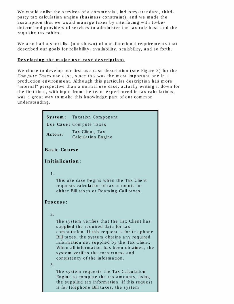
We chose to develop our first use-case description (see Figure 3) for the Compute Taxes use case, since this was the most important one in a production environment. Although this particular description has more "internal" perspective than a normal use case, actually writing it down for the first time, with input from the team experienced in tax calculations, was a great way to make this knowledge part of our common understanding.
System: Taxation Component
Use Case: Compute Taxes
Actors: Tax Client, Tax Calculation Engine
Basic Course
Initialization:
1.
This use case begins when the Tax Client requests calculation of tax amounts for either Bill taxes or Roaming Call taxes.
Process:
2.
The system verifies that the Tax Client has supplied the required data for tax computation. If this request is for telephone Bill taxes, the system obtains any required information not supplied by the Tax Client. When all information has been obtained, the system verifies the correctness and consistency of the information.
3.
The system requests the Tax Calculation Engine to compute the tax amounts, using the supplied tax information. If this request is for telephone Bill taxes, the system

performs any post-processing on those tax amounts (e.g., resetting tax amounts for tax-exempt customers, or computing tax-on-tax amounts).
Termination:
4.
The system returns the tax amounts to the Tax Client, and this use case ends.
Exceptions
Exception: Error Detected
1.
If an error is detected at any point in the tax preparation or calculation, the system will inform the Tax Client of the error. This use case ends.
Figure 3: Use case description for Compute Taxes
At this point, just a couple of days into the project, we had determined:
● Our actors (Billing System, Customer Service System, Tax Administrator, Tax Calculation Engine, Tax Rule Base and Tax Tables)
● Our major use cases (Compute Taxes and Manage Taxes)
● Two scenarios within the Compute Taxes use case (Compute Bill Taxes and Compute Roaming Taxes)
● A description of the system's operational personality for the Computing Taxes use case.
And this was about all the documentation we produced. We just didn't need any more at this point.
Identifying the major classes/components of the domain being modeled
Our architectural goal in this project was to produce a taxation component. In its simplest definition, a component is a software entity that
1. Provides a set of defined functionality as requestable services.
2. Exposes its services through defined public interfaces.

3. Exposes none of its internal implementation.
Figure 4 shows a simple UML diagram illustrating the component interfaces, Calc_Bill_Tax( ) and Calc_Roamer_Tax( ), on the taxation component. As we explored the uses of the taxation component, we learned that the billing system would require access to both Bill and Roaming tax calculations, but the Customer Service System would need access only to the Bill Tax service. The diagram reflects this.
Figure 4: Taxation component with interfaces
Now our team was at a point where we had to look inside the component and define the classes that actually composed it. Figure 5 shows the initial model the team developed, which consisted of three classes:
● The public TaxRequest class that supplies the Calc_Bill_Tax( ) and Calc_Roamer_Tax( ) operations.
● The private TaxGuard class that assures the integrity of the tax data.
● The private TaxEngineInterface class that hides the vendor-specific interface to the Tax Calculation Engine (actor), which actually performs the tax calculations.
Figure 5: Internal classes of taxation component
Defining responsibilities and relationships for each class in the domain

Naming the classes is not sufficient. I adhere rigorously to Rebecca Wirfs-Brock's practice of responsibility-driven analysis.2 In this approach, classes are not characterized by their data or their methods; rather, each class has a defined set of responsibilities that are completely separate from every other class's responsibilities. The methods (operations) and data defined in the class must serve these responsibilities -- not the other way around.
Table 3 shows our classes and their responsibilities:
Table 3: Classes and responsibilities for constructing an initial analysis class diagram.
Class name Responsibilities
TaxRequest● Assures proper sequence of
Tax Calculation process.
● Returns calculated tax amounts, or exceptions, to Tax Client.
● Performs any needed processing after Tax Calculation engine's calculations.
TaxGuard● Assures completeness and
integrity of tax-related data.
● Identifies link area data exceptions that prevent Tax Engine from being called.
TaxEngine● Encapsulates the third party
Tax Calculation engine.
● Informs TaxRequest of any errors or exceptions that have occurred during tax calculations.
Constructing an initial analysis class diagram.
Given these responsibilities, we quickly developed the UML class diagram shown in Figure 6.
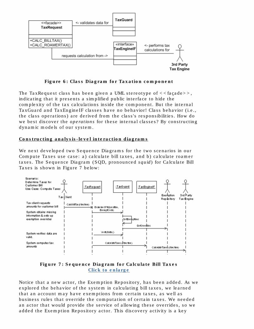
Figure 6: Class Diagram for Taxation component
The TaxRequest class has been given a UML stereotype of <<façade>>, indicating that it presents a simplified public interface to hide the complexity of the tax calculations inside the component. But the internal TaxGuard and TaxEngineIF classes have no behavior! Class behavior (i.e., the class operations) are derived from the class's responsibilities. How do we best discover the operations for these internal classes? By constructing dynamic models of our system.
Constructing analysis-level interaction diagrams
We next developed two Sequence Diagrams for the two scenarios in our Compute Taxes use case: a) calculate bill taxes, and b) calculate roamer taxes. The Sequence Diagram (SQD, pronounced squid) for Calculate Bill Taxes is shown in Figure 7 below:
Figure 7: Sequence Diagram for Calculate Bill TaxesClick to enlarge
Notice that a new actor, the Exemption Repository, has been added. As we explored the behavior of the system in calculating bill taxes, we learned that an account may have exemptions from certain taxes, as well as business rules that override the computation of certain taxes. We needed an actor that would provide the service of allowing these overrides, so we added the Exemption Repository actor. This discovery activity is a key

benefit of developing UML dynamic diagrams such as Sequence Diagrams, Collaboration Diagrams, and Activity Diagrams. Groups that only do static Class Diagrams are severely handicapped in their ability to fully characterize the system under discussion.
Challenging the interaction diagrams, updating the Class Diagrams
When we had challenged and accepted this Sequence Diagram, we updated the Class Diagram to add the operations corresponding to the messages in the SQD. To do this, we promoted each message into an operation within the class of the object receiving that message. For example, on the SQD, an instance of the class TaxGuard receives a message named Examine&Fill( ); therefore, we added an operation to the class TaxGuard to represent a method ExamineandFill( ). The updated Class Diagram is shown in Figure 8.
Figure 8: Updated class diagram for Taxation component
In the TaxGuard class we have specified two public (+) operations, and a private (-) SetExemptions( ) operation. The business rules of the system made it clear that SetExemptions( ) is called only within the ExamineandFill( ) operation, and should not be called in any other context.
Developing the implementation model
The last step in our process is unique within our method of applying agile RUP and UML to a COBOL or C project. We have to transform our object-oriented thinking into a procedural or structured representation for the target language. Developing the implementation model requires that we have a clear understanding of the scoping semantics of the target language. Since procedural languages do not have native concepts of public or private access, we must use the language features to emulate these concepts.
For example, in COBOL a subprogram is a separately compiled program. The CALL verb transfers control to a subprogram linked into the system executable image. How do you hide access to a given subprogram to emulate private access, or prevent access to a class that is internal to a component? The COBOL language allows the programmer to define either internal or external subprograms. Some degree of information hiding can

be emulated through the COBOL rules determining who can call a subprogram, with the IS GLOBAL clause on data fields, and by passing parameters BY REFERENCE (the default) or BY CONTENT -- what C and C++ programmers know as by value.
Another topic of some interest is the level of traceability you may want to capture between your object models and your code. In our project, we chose two-way traceability: We wanted to be able to start with the Class Diagrams and map those classes to their implementation in the COBOL programs, or to start with the code and be able to trace the COBOL code back to the classes on the Class Diagrams and interaction diagrams.
Figure 9 shows a schematic version of our implementation model on this project. Note that both the Billing program and Customer Service program CALL a subprogram .TAXREQUEST' (which is the class name), invoking a COBOL paragraph named .TXRQ$CALC_BILL_TAX', or ‘TXRQ$CALC_ROAMER_TAX'. What's with these weird names? Here we freely borrowed the idea of name decoration (also known as name-mangling) from C++. The C++ (and C# and Java) compilers rename every method in a class to a form that is roughly:
<classname>D<methodname>D<parameter-list>
where D represents a compiler-specific delimiter. For example, if you have a class called Account that has a method called open( float amount), the programmer would invoke Account.open( float amount ), but the compiler will produce a "decorated" function call to something like: Account$open%1F(amount). This format is guaranteed to produce a unique name for any method in a class.
As shown in Figure 9, we did a straightforward application of name decoration as a naming convention for all subprogram entry points in our COBOL system. Unlike a compiler-enforced language feature, our convention required error-prone human compliance, so the team agreed to the convention and to perform code reviews to ensure compliance.

Figure 9: Schematic representation of COBOL implementation model
Click to enlarge
Now we had a convention that supported the two-way traceability we wanted, as shown in Figure 10.
Figure 10: Traceability between Class and COBOL implementation
It's a simple trick, and it works very effectively. Each procedural language has its own scoping rules, but name-decorating is required in all of these languages.
We've come to the end of the case study. With the level of modeling and translation convention I have described, the programmers on the team were ready to start rewriting and refactoring the existing taxation code

into our new Taxation component. As they began working with the first iteration, our "leader" team began modeling the other Calculate Roamer Taxes scenario in our Compute Taxes use case. We moved fast, and light, and followed the "core" practices of RUP in a very agile fashion.
The implications for non-OO project teams
I promised to come back to a question I posed early in this article: Why should an organization give up all the techniques they know for new practices they don't know?
Let's address this first from the perspective of process change. Does my case study suggest that your organization should change from a waterfall process and move to the unknowns of an "iterative" process like RUP? The answer is no, you don't have to, but you probably should. Quality improvement must occur along multiple dimensions. Using UML to capture and organize your concepts and document them in a standardized fashion is only one of these dimensions. Others dimensions are:
● Business process
● Staffing and training
● Standardization for reuse
● Compensation plans
● Management accountability reform, and so forth
The major reason to move to an iterative process such as agile RUP is to achieve maximum visibility in project management -- knowing whether or not your project is on schedule and on target in meeting the system's requirements. Another big payoff is being able to see, and show your customer, actual working code every few weeks. It's a win-win proposition.
Now, let's also consider the question about moving to an unfamiliar process from a project and cultural perspective. Do the techniques I have described in the case study mean your organization never has to move to an OO language? Certainly not, but without direct object-orientation support you are, at best, using a handsaw when a power saw is what you need. However, these techniques will allow you to move incrementally toward further quality improvements in project management, code quality, documentation, internal and external communication, and more.
Do these techniques mean you have to train your whole team in RUP and UML? Yes, but to varying degrees. System analysts and those producing the models must understand UML in some depth. Quality assurance, project management, and developers need to be able to read UML artifacts, but not necessarily produce them. Everyone has to understand their role and responsibilities in the development process. You will have to either grow your own object modelers to produce the models and lead the agile process definition, or you will need to hire people with these skills.
One last question: What about using CASE tools to capture our models? I am a believer in CASE tools until they become an end in themselves. A CASE tool that supports UML modeling and is flexible enough to be tailored to an agile process approach can be a great aid. But beware of updating every model just because an operation name has changed. In fact, while I invariably use a CASE tool on my consulting projects, I do not enter the models into the tool until the models become stable. If you let the tool be your master, you will spend all your time serving the demands of the tool rather than developing working software. And proper use of a modern OO CASE tool has an additional benefit: It allows the team members to upgrade their skills with additional software development techniques, and the employer to acquire better skills within its work force.
Final suggestions
I have described the important aspects of using an agile object-organized approach on a pure COBOL project. I hope I have conveyed that UML and RUP are tools that can be tailored in rather unlikely ways to produce business value for the many procedural software shops still generating new applications.
Because this approach is only "object-organized," and not object-oriented, there are certainly pitfalls you must be aware of. For example, you can model inheritance or polymorphism in UML, but you will have a very difficult time implementing those charactersitics of OO programming in C or COBOL. Similarly, aggregation and composition are concepts not supported directly by any procedural language, and to implement these you will have to rely on convention and team communication.
Keep in mind that you can appropriate as much, or as little, of the object paradigm as you want. Use cases themselves are not object-oriented at all. Structural models such as class diagrams establish the main business concepts and their relationships. Behavioral models, such as sequence diagrams, let you "run" the system on paper, but they require a cohesive, object-oriented mindset. Evolve your use of both approaches and train key people on an as-needed basis. You don't have to throw away anything you currently know. My bottom-line recommendation is: Use the object-oriented paradigm to supplement your structured approach. If we can do this in COBOL, we can do it for any language!
Notes
1 Martin Fowler and Kendall Scott. UML Distilled. Addison-Wesley, 1997, p. 55.
2 Rebecca Wirfs-Brock, et. al. Designing Object-Oriented Software. Prentice Hall, 1990.
3 Some of these ideas were shared by Umar Janjua.

For more information on the products or services discussed in this article, please click here and follow the instructions provided. Thank you!
Copyright Rational Software 2003 | Privacy/Legal Information