Embed Size (px)
Citation preview
Agilent 4285A Precision LCR Meter (Including Option 001, 002, 201, 202, 301)
Maintenance Manual
SERIAL NUMBERS
This manual applies directly to instruments whose serial number prefix is 3009J-, and whose ROM-based firmware is version 01.00. For additional important information about serial numbers, read CHAPTER 1, SERIAL NUMBER of the 4285A Operation Manual.
'. ; .' '-::';~:" Agilent Technologies
Agilent Part No. 04285-90030 Printed in JAPAN April 2000
Second Edition
Notice The information contained in this document is subject to change without notice.
This document contains proprietary information that is protected by copyright. All rights are reserved. No part of this document may be photocopied, reproduced, or translated to another language without the prior written consent of the Agilent Technologies.
Agilent Technologies Japan, Ltd. Component Test PGU-Kobe 1-3-2, Murotani, Nishi-ku, Kobe-shi, Hyogo, 651-2241 Japan
©Copyright 1990, 2000 Agilent Technologies Japan, Ltd.

Manual Printing History The manual printing date and part number indicate its current edition. The printing date changes when a new edition is printed. (Minor corrections and updates that are incorporated at reprint do not cause the date to change.) The manual part number changes when extensive technical changes are incorporated.
April 1990 ............................................ First Edition (part number: 04285-90030)
April 2000 ......................................... Second Edition (part number: 04285-90030)
iii
Certification Agilent Technologies certifies that this product met its published specifications at the time of shipment from the factory. Agilent Technologies further certifies that its calibration measurements are traceable to the United States National Institute of Standards and Technology, to the extent allowed by the Institution's calibration facility, or to the calibration facilities of other International Standards Organization members.
Warranty This Agilent Technologies instrument product is warranted against defects in material and workmanship for a period of one year from the date of shipment, except that in the case of certain components listed in General Information of this manual, the warranty shall be for the specified period. During the warranty period, Agilent Technologies will, at its option, either repair or replace products that prove to be defective.
For warranty service or repair, this product must be returned to a service facility designated by Agilent Technologies. Buyer shall prepay shipping charges to Agilent Technologies and Agilent Technologies shall pay shipping charges to return the product to Buyer. However, Buyer shall pay all shipping charges, duties, and taxes for products returned to Agilent Technologies from another country.
Agilent Technologies warrants that its software and firmware designated by Agilent Technologies for use with an instrument will execute its programming instruction when property installed on that instrument. Agilent Technologies does not warrant that the operation of the instrument, or software, or firmware will be uninterrupted or error free.
Limitation Of Warranty The foregoing warranty shall not apply to defects resulting from improper or inadequate maintenance by Buyer, Buyer-supplied software or interfacing, unauthorized modification or misuse, operation outside the environmental specifications for the product, or improper site preparation or maintenance.
No other warranty is expressed or implied. Agilent Technologies specifically disclaims the implied warranties of merchantability andfitnessJor a particular purpose.
iv
Exclusive Remedies The remedies provided herein are buyer's sole and exclusive remedies. Agilent Technologies shall not be liable for any direct, indirect, special, incidental, or consequential damages, whether based on contract, tort, or any other legal theory.
Assistance Product maintenance agreements and other customer assistance agreements are available for Agilent Technologies products.
For any assistance, contact your nearest Agilent Technologies Sales and Service Office. Addresses are provided at the back of this manual.
v
Safety Summary The following general safety precautions must be observed during all phases of operation, service, and repair of this instrument. Failure to comply with these precautions or with specific WARNINGS elsewhere in this manual may impair the protection provided by the equipment. In addition it violates safety standards of design, manufacture, and intended use of the instrument. The Agilent Technologies assumes no liability for the customer's failure to comply with these requirements.
Ground The Instrument
To avoid electric shock hazard, the instrument chassis and cabinet must be connected to a safety earth ground by the supplied power cable with earth blade.
DO NOT Operate In An Explosive Atmosphere
Do not operate the instrument in the presence of flammable gasses or fumes. Operation of any electrical instrument in such an environment constitutes a definite safety hazard.
Keep Away From Live Circuits
Operating personnel must not remove instrument covers. Component replacement and internal adjustments must be made by qualified maintenance personnel. Do not replace components with the power cable connected. Under certain conditions, dangerous voltages may exist even with the power cable removed. To avoid injuries, always disconnect power and discharge circuits before touching them.
DO NOT Service Or Adjust Alone
Do not attempt internal service or adjustment unless another person, capable of rendering first aid and resuscitation, is present.
DO NOT Substitute Parts Or Modify Instrument
Because of the danger of introducing additional hazards, do not install substitute parts or perform unauthorized modifications to the instrument. Return the instrument to a Agilent Technologies Sales and Service Office for service and repair to ensure that safety features are maintained.
Dangerous Procedure Warnings
Warnings , such as the example below, precede potentially dangerous procedures throughout this manual. Instructions contained in the warnings must be followed.
Warning
vi
Dangerous voltages, capable of causing death, are present in this instrument. Use extreme caution when handling, testing, and adjusting this instrument.
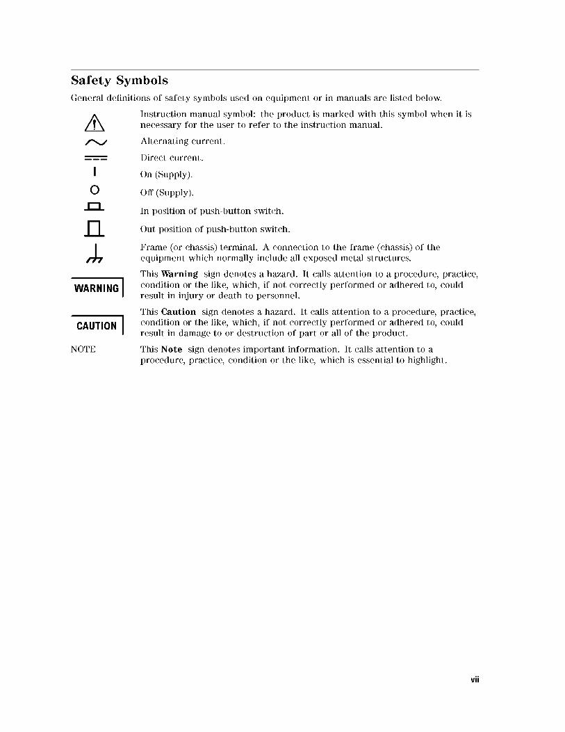
Safety Symbols General definitions of safety symbols used on equipment or in manuals are listed below.
o ...c:J...
I WARNING I
I CAUTION I NOTE
Instruction manual symbol: the product is marked with this symbol when it is necessary for the user to refer to the instruction manual.
Alternating current.
Direct current.
On (Supply).
Off (Supply) .
In position of push-button switch.
Out position of push-button switch.
Frame ( or chassis) terminal. A connection to the frame ( chassis) of the equipment which normally include all exposed metal structures.
This Warning sign denotes a hazard. It calls attention to a procedure, practice, condition or the like, which, if not correctly performed or adhered to, could result in injury or death to personnel.
This Caution sign denotes a hazard. It calls attention to a procedure, practice, condition or the like, which, if not correctly performed or adhered to, could result in damage to or destruction of part or all of the product.
This Note sign denotes important information. It calls attention to a procedure, practice, condition or the like, which is essential to highlight.
vii

HOW TO USE THIS MANUAL This manual consists of Chapter 1 (Performance Tests). Chapter 1 provides the information to performance test the 4285A.
viii
4285A Precision LCR Meter Documentation Map
Getting Started Guide
The Getting Started Guide walks you through system setup and initial power-up, shows how to make basic measurements and explains commonly used features.
Operation Manual
The Operation Manual provides general information, specifications, GPIB programing information, and in depth reference information.
Maintenance Manual
The Maintenance Manual explains how to verify conformance to published specifications.
Service Manual
The Service Manual explains how to adjust troubleshoot, and repair the instrument.
ix
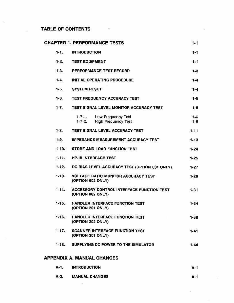
TABLE OF CONTENTS
CHAPTER 1. PERFORMANCE TESTS 1-1
1-1. INTRODUCTION 1-1
1-2. TEST EQUIPMENT 1-1
1-3. PERFORMANCE TEST RECORD 1-3
1-4. INITIAL OPERATING PROCEDURE 1-4
1-5. SYSTEM RESET 1-4
1-6. TEST FREQUENCY ACCURACY TEST 1-5
1-7. TEST SIGNAL LEVEL MONITOR ACCURACY TEST 1-6
1-7 -1. Low Frequency Test 1-6 1-7-2. High Frequency Test 1-8
1-8. TEST SIGNAL LEVEL ACCURACY TEST 1-11
1-9. IMPEDANCE MEASUREMENT ACCURACY TEST 1-13
1-10. STORE AND LOAD FUNCTION TEST 1-24
1-11. HP-IB INTERFACE TEST 1-25
1-12. DC BIAS LEVEL ACCURACY TEST (OPTION 001 ONLY) 1-27
1-13. VOLTAGE RATIO MONITOR ACCURACY TEST 1-29 (OPTION 002 ONLY)
1-14. ACCESSORY CONTROL INTERFACE FUNCTION TEST 1-31 (OPTION 002 ONLY)
1-15. HANDLER INTERFACE FUNCTION TEST 1-34 (OPTION 201 ONLY)
1-16. HANDLER INTERFACE FUNCTION TEST 1-38 (OPTION 202 ONLY)
1-17. SCANNER INTERFACE FUNCTION TEST 1-41 (OPTION 301 ONLY)
1-18. SUPPLYING DC POWER TO THE SIMULATOR 1-44
APPENDIX A. MANUAL CHANGES
A-1. INTRODUCTION A-1
A-2. MANUAL CHANGES A-1
○C Copyright 2012 Agilent Technologies
Agilent 4285A Precision LCR Meter Maintenance Manual
Manual Change
Agilent Part No. N/A
June 2012
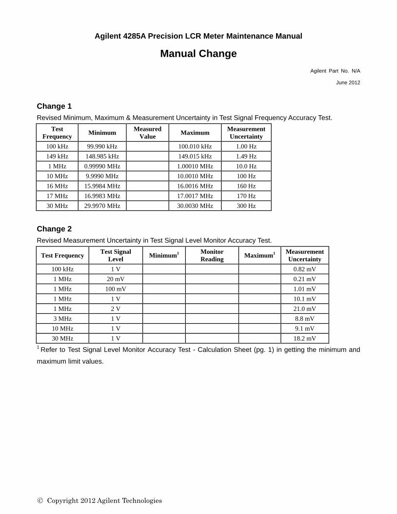
Change 1
Revised Minimum, Maximum & Measurement Uncertainty in Test Signal Frequency Accuracy Test.
Test
Frequency Minimum
Measured
Value Maximum
Measurement
Uncertainty
100 kHz 99.990 kHz 100.010 kHz 1.00 Hz
149 kHz 148.985 kHz 149.015 kHz 1.49 Hz
1 MHz 0.99990 MHz 1.00010 MHz 10.0 Hz
10 MHz 9.9990 MHz 10.0010 MHz 100 Hz
16 MHz 15.9984 MHz 16.0016 MHz 160 Hz
17 MHz 16.9983 MHz 17.0017 MHz 170 Hz
30 MHz 29.9970 MHz 30.0030 MHz 300 Hz
Change 2
Revised Measurement Uncertainty in Test Signal Level Monitor Accuracy Test.
Test Frequency Test Signal
Level Minimum
1 Monitor
Reading Maximum
1 Measurement
Uncertainty
100 kHz 1 V 0.82 mV
1 MHz 20 mV 0.21 mV
1 MHz 100 mV 1.01 mV
1 MHz 1 V 10.1 mV
1 MHz 2 V 21.0 mV
3 MHz 1 V 8.8 mV
10 MHz 1 V 9.1 mV
30 MHz 1 V 18.2 mV
1 Refer to Test Signal Level Monitor Accuracy Test - Calculation Sheet (pg. 1) in getting the minimum and
maximum limit values.
○C Copyright 2012 Agilent Technologies
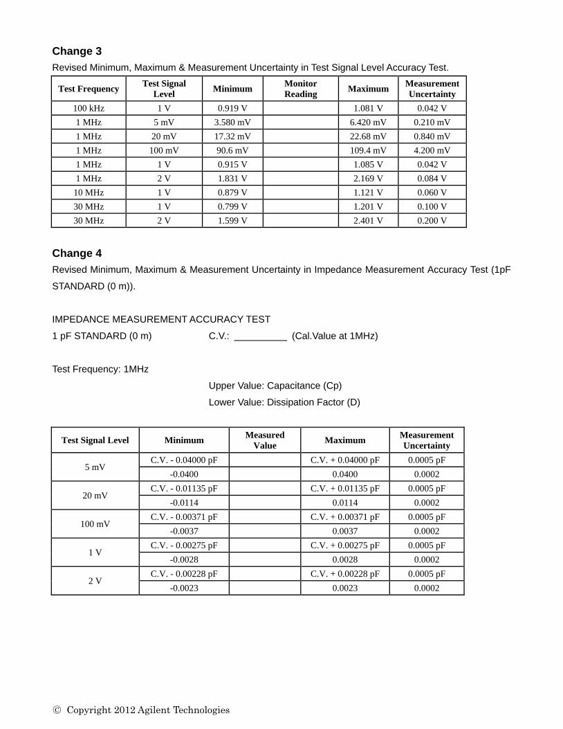
Change 3
Revised Minimum, Maximum & Measurement Uncertainty in Test Signal Level Accuracy Test.
Test Frequency Test Signal
Level Minimum
Monitor
Reading Maximum
Measurement
Uncertainty
100 kHz 1 V 0.919 V 1.081 V 0.042 V
1 MHz 5 mV 3.580 mV 6.420 mV 0.210 mV
1 MHz 20 mV 17.32 mV 22.68 mV 0.840 mV
1 MHz 100 mV 90.6 mV 109.4 mV 4.200 mV
1 MHz 1 V 0.915 V 1.085 V 0.042 V
1 MHz 2 V 1.831 V 2.169 V 0.084 V
10 MHz 1 V 0.879 V 1.121 V 0.060 V
30 MHz 1 V 0.799 V 1.201 V 0.100 V
30 MHz 2 V 1.599 V 2.401 V 0.200 V
Change 4
Revised Minimum, Maximum & Measurement Uncertainty in Impedance Measurement Accuracy Test (1pF
STANDARD (0 m)).
IMPEDANCE MEASUREMENT ACCURACY TEST
1 pF STANDARD (0 m) C.V.: (Cal.Value at 1MHz)
Test Frequency: 1MHz
Upper Value: Capacitance (Cp)
Lower Value: Dissipation Factor (D)
Test Signal Level Minimum Measured
Value Maximum
Measurement
Uncertainty
5 mV C.V. - 0.04000 pF C.V. + 0.04000 pF 0.0005 pF
-0.0400 0.0400 0.0002
20 mV C.V. - 0.01135 pF C.V. + 0.01135 pF 0.0005 pF
-0.0114 0.0114 0.0002
100 mV C.V. - 0.00371 pF C.V. + 0.00371 pF 0.0005 pF
-0.0037 0.0037 0.0002
1 V C.V. - 0.00275 pF C.V. + 0.00275 pF 0.0005 pF
-0.0028 0.0028 0.0002
2 V C.V. - 0.00228 pF C.V. + 0.00228 pF 0.0005 pF
-0.0023 0.0023 0.0002
○C Copyright 2012 Agilent Technologies
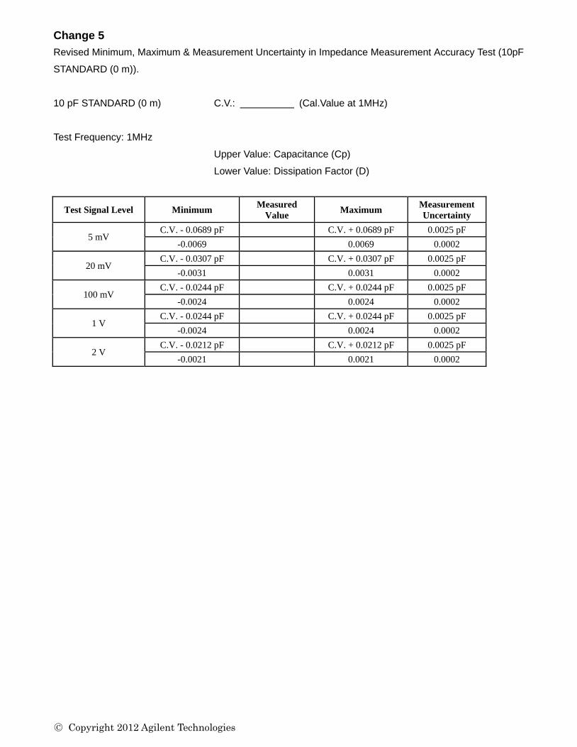
Change 5
Revised Minimum, Maximum & Measurement Uncertainty in Impedance Measurement Accuracy Test (10pF
STANDARD (0 m)).
10 pF STANDARD (0 m) C.V.: (Cal.Value at 1MHz)
Test Frequency: 1MHz
Upper Value: Capacitance (Cp)
Lower Value: Dissipation Factor (D)
Test Signal Level Minimum Measured
Value Maximum
Measurement
Uncertainty
5 mV C.V. - 0.0689 pF C.V. + 0.0689 pF 0.0025 pF
-0.0069 0.0069 0.0002
20 mV C.V. - 0.0307 pF C.V. + 0.0307 pF 0.0025 pF
-0.0031 0.0031 0.0002
100 mV C.V. - 0.0244 pF C.V. + 0.0244 pF 0.0025 pF
-0.0024 0.0024 0.0002
1 V C.V. - 0.0244 pF C.V. + 0.0244 pF 0.0025 pF
-0.0024 0.0024 0.0002
2 V C.V. - 0.0212 pF C.V. + 0.0212 pF 0.0025 pF
-0.0021 0.0021 0.0002

○C Copyright 2012 Agilent Technologies
Change 6
Revised Minimum, Maximum & Measurement Uncertainty in Impedance Measurement Accuracy Test
(100pF STANDARD (0 m)).
100 pF STANDARD (0 m) C.V.: (Cal.Value at 1MHz)
Test Frequency: 1MHz
Upper Value: Capacitance (Cp)
Lower Value: Dissipation Factor (D)
Test Signal Level Minimum Measured
Value Maximum
Measurement
Uncertainty
5 mV C.V. - 0.636 pF C.V. + 0.636 pF 0.0250 pF
-0.0064 0.0064 0.0002
20 mV C.V. - 0.222 pF C.V. + 0.222 pF 0.0250 pF
-0.0022 0.0022 0.0002
100 mV C.V. - 0.153 pF C.V. + 0.153 pF 0.0250 pF
-0.0015 0.0015 0.0002
1 V C.V. - 0.153 pF C.V. + 0.153 pF 0.0250 pF
-0.0015 0.0015 0.0002
2 V C.V. - 0.218 pF C.V. + 0.218 pF 0.0250 pF
-0.0022 0.0022 0.0002
○C Copyright 2012 Agilent Technologies
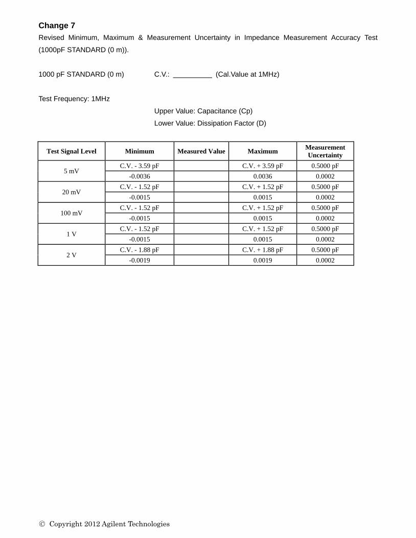
Change 7
Revised Minimum, Maximum & Measurement Uncertainty in Impedance Measurement Accuracy Test
(1000pF STANDARD (0 m)).
1000 pF STANDARD (0 m) C.V.: (Cal.Value at 1MHz)
Test Frequency: 1MHz
Upper Value: Capacitance (Cp)
Lower Value: Dissipation Factor (D)
Test Signal Level Minimum Measured Value Maximum Measurement
Uncertainty
5 mV C.V. - 3.59 pF C.V. + 3.59 pF 0.5000 pF
-0.0036 0.0036 0.0002
20 mV C.V. - 1.52 pF C.V. + 1.52 pF 0.5000 pF
-0.0015 0.0015 0.0002
100 mV C.V. - 1.52 pF C.V. + 1.52 pF 0.5000 pF
-0.0015 0.0015 0.0002
1 V C.V. - 1.52 pF C.V. + 1.52 pF 0.5000 pF
-0.0015 0.0015 0.0002
2 V C.V. - 1.88 pF C.V. + 1.88 pF 0.5000 pF
-0.0019 0.0019 0.0002
○C Copyright 2012 Agilent Technologies
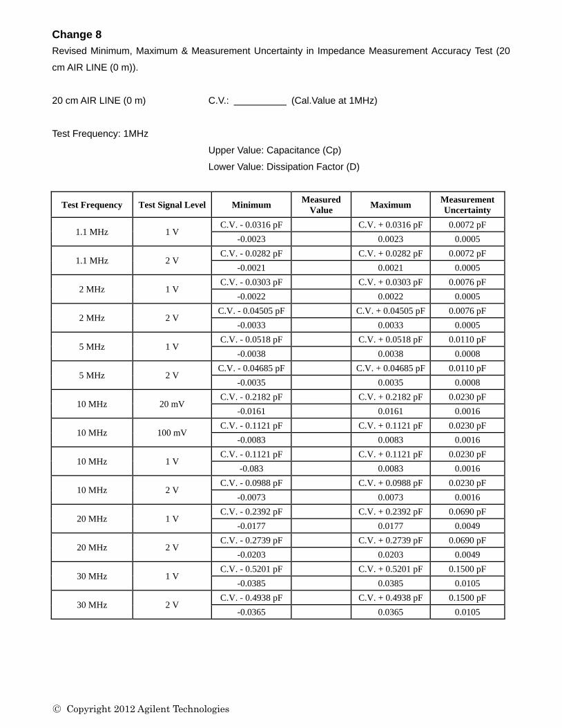
Change 8
Revised Minimum, Maximum & Measurement Uncertainty in Impedance Measurement Accuracy Test (20
cm AIR LINE (0 m)).
20 cm AIR LINE (0 m) C.V.: (Cal.Value at 1MHz)
Test Frequency: 1MHz
Upper Value: Capacitance (Cp)
Lower Value: Dissipation Factor (D)
Test Frequency Test Signal Level Minimum Measured
Value Maximum
Measurement
Uncertainty
1.1 MHz 1 V C.V. - 0.0316 pF C.V. + 0.0316 pF 0.0072 pF
-0.0023 0.0023 0.0005
1.1 MHz 2 V C.V. - 0.0282 pF C.V. + 0.0282 pF 0.0072 pF
-0.0021 0.0021 0.0005
2 MHz 1 V C.V. - 0.0303 pF C.V. + 0.0303 pF 0.0076 pF
-0.0022 0.0022 0.0005
2 MHz 2 V C.V. - 0.04505 pF C.V. + 0.04505 pF 0.0076 pF
-0.0033 0.0033 0.0005
5 MHz 1 V C.V. - 0.0518 pF C.V. + 0.0518 pF 0.0110 pF
-0.0038 0.0038 0.0008
5 MHz 2 V C.V. - 0.04685 pF C.V. + 0.04685 pF 0.0110 pF
-0.0035 0.0035 0.0008
10 MHz 20 mV C.V. - 0.2182 pF C.V. + 0.2182 pF 0.0230 pF
-0.0161 0.0161 0.0016
10 MHz 100 mV C.V. - 0.1121 pF C.V. + 0.1121 pF 0.0230 pF
-0.0083 0.0083 0.0016
10 MHz 1 V C.V. - 0.1121 pF C.V. + 0.1121 pF 0.0230 pF
-0.083 0.0083 0.0016
10 MHz 2 V C.V. - 0.0988 pF C.V. + 0.0988 pF 0.0230 pF
-0.0073 0.0073 0.0016
20 MHz 1 V C.V. - 0.2392 pF
C.V. + 0.2392 pF 0.0690 pF
-0.0177 0.0177 0.0049
20 MHz 2 V C.V. - 0.2739 pF C.V. + 0.2739 pF 0.0690 pF
-0.0203 0.0203 0.0049
30 MHz 1 V C.V. - 0.5201 pF C.V. + 0.5201 pF 0.1500 pF
-0.0385 0.0385 0.0105
30 MHz 2 V C.V. - 0.4938 pF C.V. + 0.4938 pF 0.1500 pF
-0.0365 0.0365 0.0105
○C Copyright 2012 Agilent Technologies
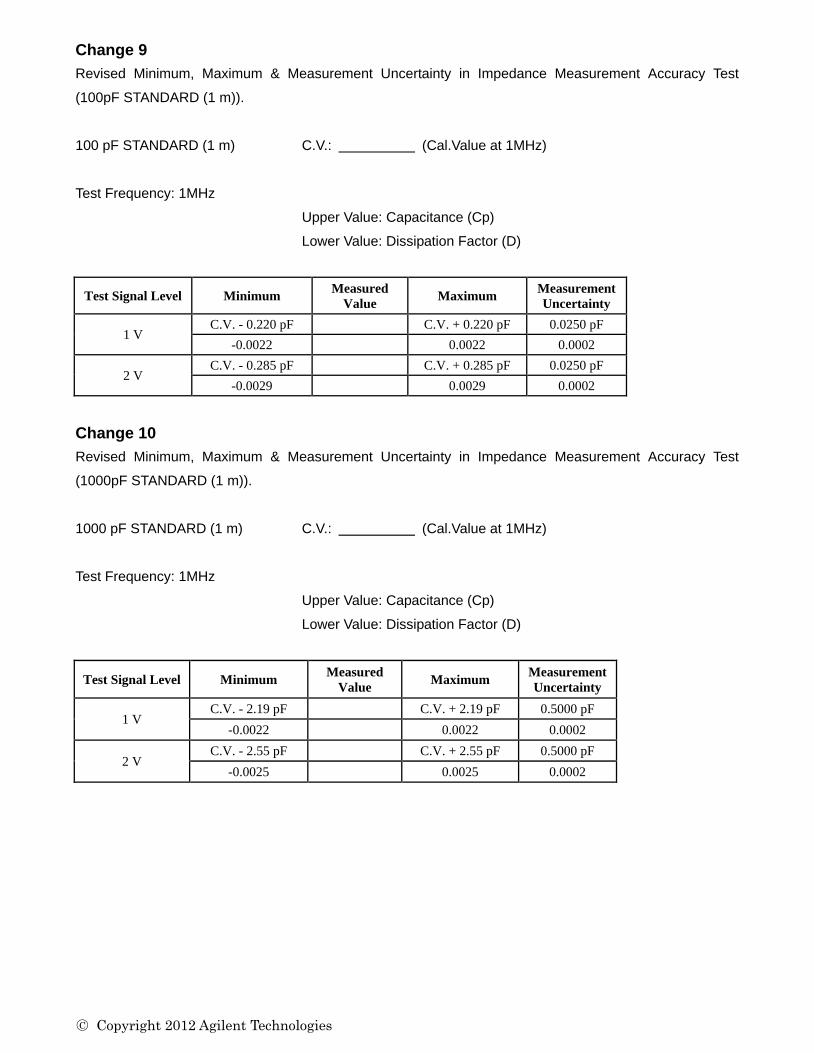
Change 9
Revised Minimum, Maximum & Measurement Uncertainty in Impedance Measurement Accuracy Test
(100pF STANDARD (1 m)).
100 pF STANDARD (1 m) C.V.: (Cal.Value at 1MHz)
Test Frequency: 1MHz
Upper Value: Capacitance (Cp)
Lower Value: Dissipation Factor (D)
Test Signal Level Minimum Measured
Value Maximum
Measurement
Uncertainty
1 V C.V. - 0.220 pF C.V. + 0.220 pF 0.0250 pF
-0.0022 0.0022 0.0002
2 V C.V. - 0.285 pF C.V. + 0.285 pF 0.0250 pF
-0.0029 0.0029 0.0002
Change 10
Revised Minimum, Maximum & Measurement Uncertainty in Impedance Measurement Accuracy Test
(1000pF STANDARD (1 m)).
1000 pF STANDARD (1 m) C.V.: (Cal.Value at 1MHz)
Test Frequency: 1MHz
Upper Value: Capacitance (Cp)
Lower Value: Dissipation Factor (D)
Test Signal Level Minimum Measured
Value Maximum
Measurement
Uncertainty
1 V C.V. - 2.19 pF C.V. + 2.19 pF 0.5000 pF
-0.0022 0.0022 0.0002
2 V C.V. - 2.55 pF C.V. + 2.55 pF 0.5000 pF
-0.0025 0.0025 0.0002
○C Copyright 2012 Agilent Technologies
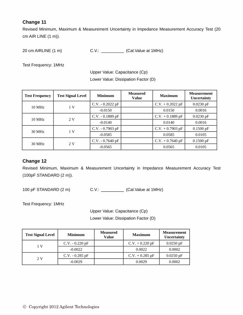
Change 11
Revised Minimum, Maximum & Measurement Uncertainty in Impedance Measurement Accuracy Test (20
cm AIR LINE (1 m)).
20 cm AIRLINE (1 m) C.V.: (Cal.Value at 1MHz)
Test Frequency: 1MHz
Upper Value: Capacitance (Cp)
Lower Value: Dissipation Factor (D)
Test Frequency Test Signal Level Minimum Measured
Value Maximum
Measurement
Uncertainty
10 MHz 1 V C.V. - 0.2022 pF C.V. + 0.2022 pF 0.0230 pF
-0.0150 0.0150 0.0016
10 MHz 2 V C.V. - 0.1889 pF C.V. + 0.1889 pF 0.0230 pF
-0.0140 0.0140 0.0016
30 MHz 1 V C.V. - 0.7903 pF C.V. + 0.7903 pF 0.1500 pF
-0.0585 0.0585 0.0105
30 MHz 2 V C.V. - 0.7640 pF C.V. + 0.7640 pF 0.1500 pF
-0.0565 0.0565 0.0105
Change 12
Revised Minimum, Maximum & Measurement Uncertainty in Impedance Measurement Accuracy Test
(100pF STANDARD (2 m)).
100 pF STANDARD (2 m) C.V.: (Cal.Value at 1MHz)
Test Frequency: 1MHz
Upper Value: Capacitance (Cp)
Lower Value: Dissipation Factor (D)
Test Signal Level Minimum Measured
Value Maximum
Measurement
Uncertainty
1 V C.V. - 0.220 pF C.V. + 0.220 pF 0.0250 pF
-0.0022 0.0022 0.0002
2 V C.V. - 0.285 pF C.V. + 0.285 pF 0.0250 pF
-0.0029 0.0029 0.0002
○C Copyright 2012 Agilent Technologies
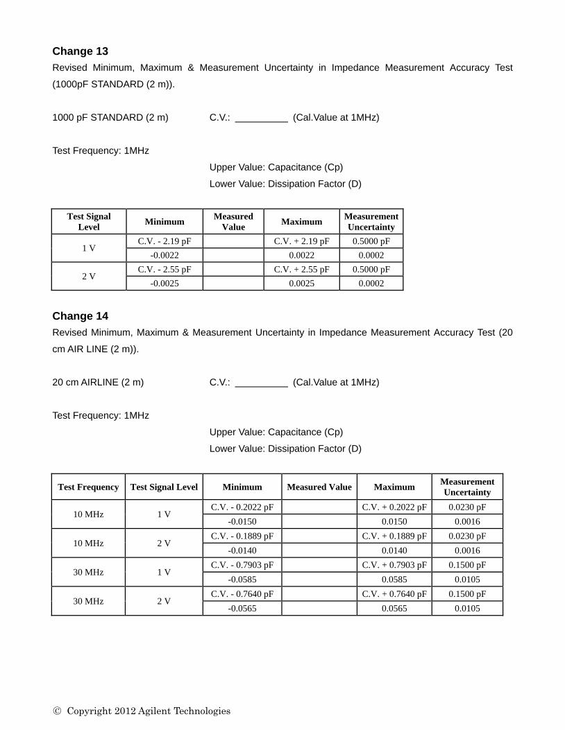
Change 13
Revised Minimum, Maximum & Measurement Uncertainty in Impedance Measurement Accuracy Test
(1000pF STANDARD (2 m)).
1000 pF STANDARD (2 m) C.V.: (Cal.Value at 1MHz)
Test Frequency: 1MHz
Upper Value: Capacitance (Cp)
Lower Value: Dissipation Factor (D)
Test Signal
Level Minimum
Measured
Value Maximum
Measurement
Uncertainty
1 V C.V. - 2.19 pF C.V. + 2.19 pF 0.5000 pF
-0.0022 0.0022 0.0002
2 V C.V. - 2.55 pF C.V. + 2.55 pF 0.5000 pF
-0.0025 0.0025 0.0002
Change 14
Revised Minimum, Maximum & Measurement Uncertainty in Impedance Measurement Accuracy Test (20
cm AIR LINE (2 m)).
20 cm AIRLINE (2 m) C.V.: (Cal.Value at 1MHz)
Test Frequency: 1MHz
Upper Value: Capacitance (Cp)
Lower Value: Dissipation Factor (D)
Test Frequency Test Signal Level Minimum Measured Value Maximum Measurement
Uncertainty
10 MHz 1 V C.V. - 0.2022 pF C.V. + 0.2022 pF 0.0230 pF
-0.0150 0.0150 0.0016
10 MHz 2 V C.V. - 0.1889 pF C.V. + 0.1889 pF 0.0230 pF
-0.0140 0.0140 0.0016
30 MHz 1 V C.V. - 0.7903 pF C.V. + 0.7903 pF 0.1500 pF
-0.0585 0.0585 0.0105
30 MHz 2 V C.V. - 0.7640 pF C.V. + 0.7640 pF 0.1500 pF
-0.0565 0.0565 0.0105
○C Copyright 2012 Agilent Technologies
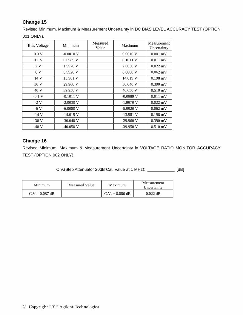
Change 15
Revised Minimum, Maximum & Measurement Uncertainty in DC BIAS LEVEL ACCURACY TEST (OPTION
001 ONLY).
Bias Voltage Minimum Measured
Value Maximum
Measurement
Uncertainty
0.0 V -0.0010 V 0.0010 V 0.001 mV
0.1 V 0.0989 V 0.1011 V 0.011 mV
2 V 1.9970 V 2.0030 V 0.022 mV
6 V 5.9920 V 6.0080 V 0.062 mV
14 V 13.981 V 14.019 V 0.198 mV
30 V 29.960 V 30.040 V 0.390 mV
40 V 39.950 V 40.050 V 0.510 mV
-0.1 V -0.1011 V -0.0989 V 0.011 mV
-2 V -2.0030 V -1.9970 V 0.022 mV
-6 V -6.0080 V -5.9920 V 0.062 mV
-14 V -14.019 V -13.981 V 0.198 mV
-30 V -30.040 V -29.960 V 0.390 mV
-40 V -40.050 V -39.950 V 0.510 mV
Change 16
Revised Minimum, Maximum & Measurement Uncertainty in VOLTAGE RATIO MONITOR ACCURACY
TEST (OPTION 002 ONLY).
C.V.(Step Attenuator 20dB Cal. Value at 1 MHz): [dB]
Minimum Measured Value Maximum Measurement
Uncertainty
C.V. - 0.087 dB C.V. + 0.086 dB 0.022 dB
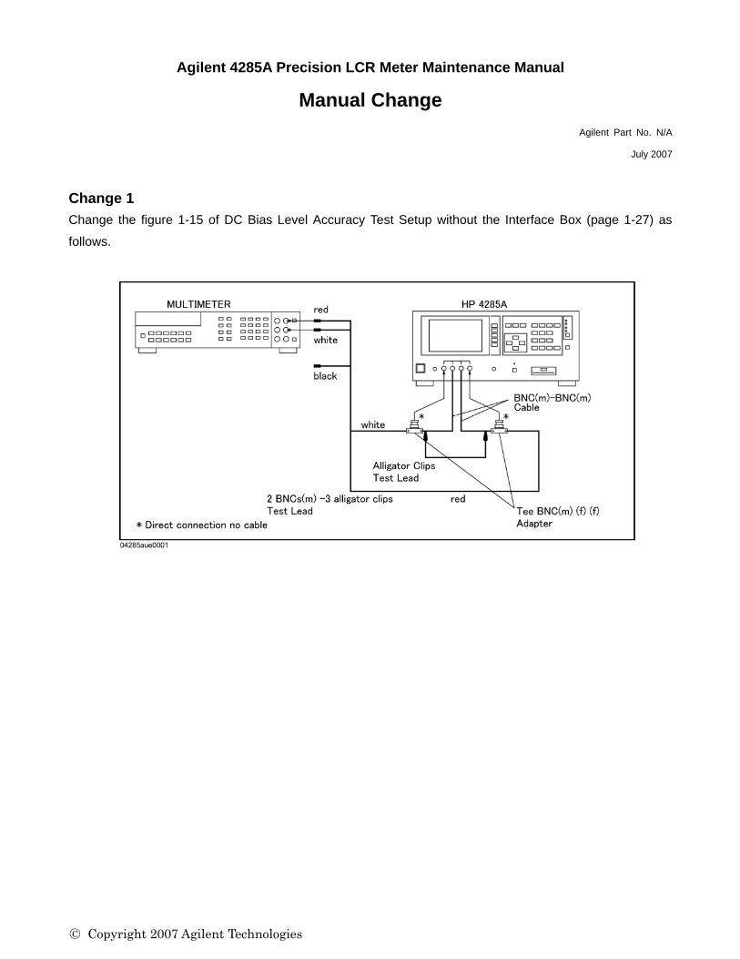
Agilent 4285A Precision LCR Meter Maintenance Manual
Manual Change Agilent Part No. N/A
July 2007
Change 1 Change the figure 1-15 of DC Bias Level Accuracy Test Setup without the Interface Box (page 1-27) as
follows.
○C Copyright 2007 Agilent Technologies

○C Copyright 2012 Agilent Technologies
CHAPTER 1
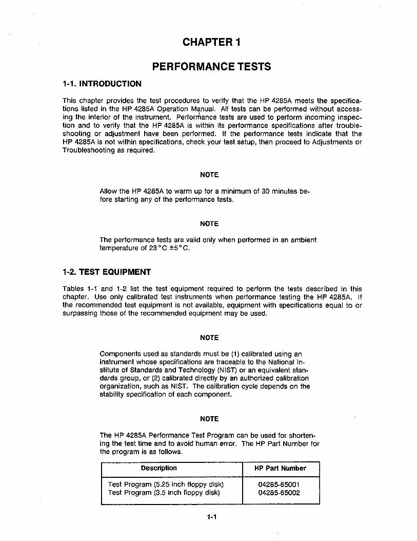
PERFORMANCE TESTS 1-1. INTRODUCTION
This chapter provides the test procedures to verify that the HP 4285A meets the specifications listed in the HP 4285A Operation Manual. All tests can be performed without access-, ing the interior of the instrument. Performance tests are used to perform incoming inspec-tion and to verify that the HP 4285A is within its performance specifications after troubleshooting or adjustment have been performed. If the performance tests indicate that the HP 4285A is not within specifications, check your test setup, then proceed to Adjustments or Troubleshooting as required.
NOTE
Allow the HP 4285A to warm up for a minimum of 30 minutes before starting any of the performance tests.
NOTE
The performance tests are valid only when performed in an ambient temperature of 23 0 C ±5° C.
1-2. TEST EQUIPMENT
Tables 1-1 and 1-2 list the test equipment required to perform the tests described in this chapter. Use only calibrated test instruments when performance testing the HP 4285A. If the recommended test equipment is not available, equipment with specifications equal to or surpassing those of the recommended equipment may be used.
NOTE
Components used as standards must be (1) calibrated using an instrument whose specifications are traceable to the National Institute of Standards and Technology (NIST) or an equivalent standards group, or (2) calibrated directly by an authorized calibration organization, such as NIST. The calibration cycle depends on the stability specification of each component.
NOTE
The HP 4285A Performance Test Program can be used for shortening the test time and to avoid human error. The HP Part Number for the program is as follows.
Description HP Part Number
Test Program (5.25 inch floppy disk) 04285-65001 Test Program (3.5 inch floppy disk) 04285-65002
1·1
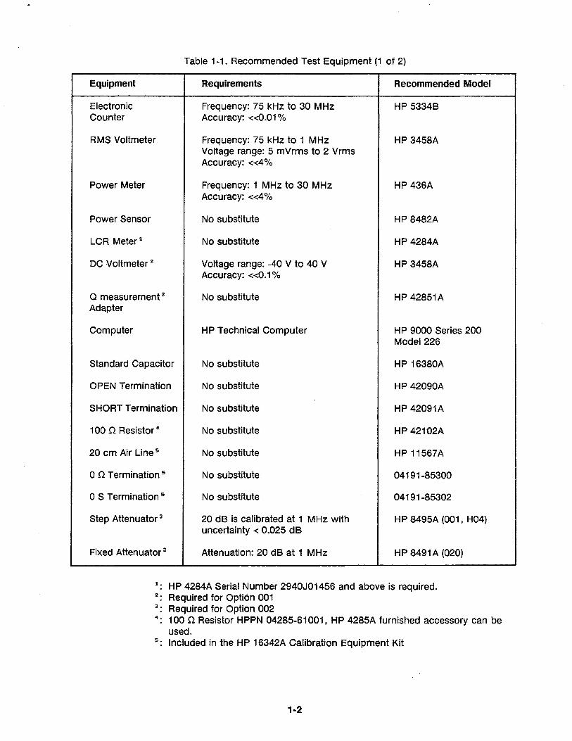
Table 1-1. Recommended Test Equipment (1 of 2)
Equipment Requirements Recommended Model
Electronic Frequency: 75 kHz to 30 MHz HP 5334B Counter Accuracy: <<0.01 %
RMS Voltmeter Frequency: 75 kHz to 1 MHz HP 3458A Voltage range: 5 mVrms to 2 Vrms Accuracy: «4%
Power Meter Frequency: 1 MHz to 30 MHz HP 436A Accuracy: «4%
Power Sensor No substitute HP 8482A
LCR Meter 1 No substitute HP 4284A
DC Voltmeter 2 Voltage range: -40 V to 40 V HP 3458A Accuracy:: <<0.1 %
Q measurement 3 No substitute HP 42851 A Adapter
Computer HP Technical Computer HP 9000 Series 200 Model 226
Standard Capacitor No substitute HP 16380A
OPEN Termination No substitute HP 42090A
SHORT Termination No substitute HP 42091A
100 n Resistor 4 No substitute HP 42102A
20 cm Air Line 5 No substitute HP 11567A
o n Termination 5 No substitute 04191-85300
o S Termination 5 No s,ubstitute 04191-85302
Step Attenuator 3 20 dB is calibrated at 1 MHz with HP 8495A (001, H04) uncertainty < 0.025 dB
Fixed Attenuator 3 Attenuation: 20 dB at 1 MHz HP 8491 A (020)
1. HP 4284A Sierial Number 2940J01456 and above is required. 2. Required for Optii6n 001 3. Required for Optiion 002 4. 100 n Resistor HPPN 04285-61001, HP 4285A furnished accessory can be
used. 5. Included in the HP 16342A Calibration Equipment Kit
1-2
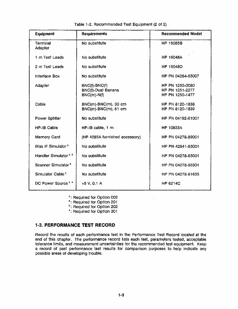
Table 1-2. Recommended Test Equipment (2 of 2)
Equipment Requirements
Terminal No substitute Adapter
1 m Test Leads No substitute
2 m Test Leads No substitute
Interface Box No substitute
Adapter BNC(f)-BNC(f) BNC(f)-Dual Banana BNC(m)-N(f)
Cable BNC(m)-BNC{m), 30 cm BNC(m)-BNC(m), 61 cm
Power Splitter No substitute
HP-IB Cable HP-IB cable, 1 m
Memory Card (HP 4285A furnished accessory)
Bias IF Simulator 1 No substitute
Handler Simulator 2 3 No substitute
Scanner Simulator 4 No substitute
Simulator Cable 3 No substitute
DC Power Source 1 4 +5V,0.1 A
1: Required for Option 002 2: Required for Option 201 3: Required for Option 202 4: Required for Option 301
1~.PERFORMANCETESTRECORD
Recommended Model
HP 16085B
HP 16048A
HP 16048D
HP PN 04284-65007
HP PN 1250-0080 HP PN 1251-2277 HP PN 1250-1477
HP PN 8120-1838 HP PN 8120-1839
HP PN 04192-61001
HP 10833A
HP PN 04278-89001
HP PN 42841-65001
HP PN 04278-65001
HP PN 04278-65301
HP PN 04278-61635
HP 6214C
Record the results of each performance test in the Performance Test Record located at the end of this chapter. The performance record lists each test, parameters tested, acceptable tolerance limits, and measurement uncertainties for the recommended test equipment. Keep a record of past performance test· results for comparison purposes to help indicate any possible areas of developing trouble.
1-3
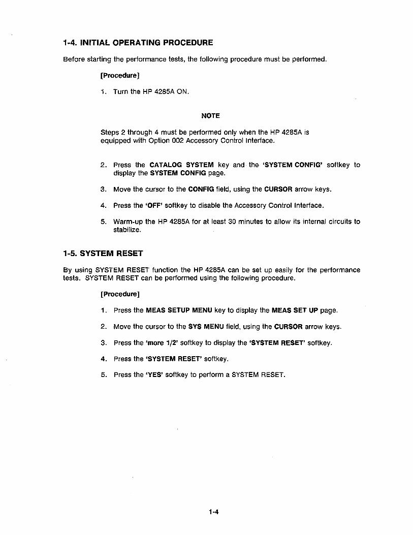
1-4. INITIAL OPERATING PROCEDURE
Before starting the performance tests, the following procedure must be performed.
[Procedure]
1. Turn the HP 4285A ON.
NOTE
Steps 2 through 4 must be performed only when the HP 4285A is equipped with Option 002 Accessory Control Interface.
2. Press the CATALOG SYSTEM key and the 'SYSTEM CON FIG' softkey to display the SYSTEM CON FIG page.
3. Move the cursor to the CON FIG field, using the CURSOR arrow keys.
4. Press the 'OFF' softkey to disable the Accessory Control Interface.
5. Warm-up the HP 4285A for at least 30 minutes to allow its internal circuits to stabilize.
1-5. SYSTEM RESET
By using SYSTEM RESET function the HP 4285A can be set up easily for the performance tests. SYSTEM RESET can be performed using the following procedure.
[Procedure]
1 . Press the MEAS SETUP MENU key to display the MEAS SET UP page.
2. Move the cursor to the SYS MENU field, using the CURSOR arrow keys.
3. Press the 'more 1/2' softkey to display the 'SYSTEM RESET' softkey.
4. Press the 'SYSTEM RESET' softkey.
5. Press the 'YES' softkey to perform a SYSTEM RESET.
1-4
PERFORMANCE TESTS
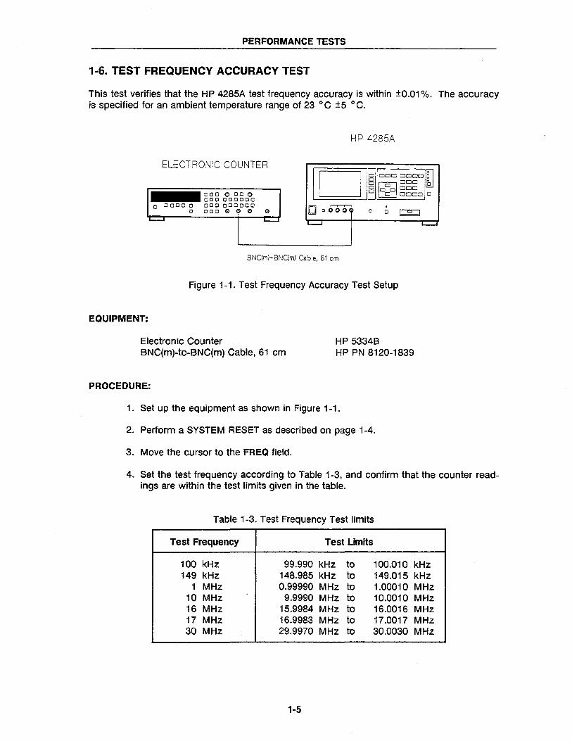
1-6. TEST FREQUENCY ACCURACY TEST
This test verifies that the HP 4285A test frequency accuracy is within ±0.01 %. The accuracy is specified for an ambient temperature range of 23°C ±5 °C.
HP 4285A
ELECTRONIC COUNTER
D~DDDD~~ 8 ~DDD 0 o 00 000
_ClClClOCICIO o 0 0000 CI CI CI CI CI CI CI CI CI CI
CI CICICICI CI CICICI ClCICICIOO o 0 000i CI CICIO e e e 0 CI I = I ......... L...-J L---I
BNC(m)-BNC(m) Cable. 61 em
Figure 1-1. Test Frequency Accuracy Test Setup
EQUIPMENT:
Electronic Counter BNC(m)-to-BNC(m) Cable, 61 cm
PROCEDURE:
HP 5334B HP PN 8120-1839
1. Set up the equipment as shown in Figure 1-1.
2. Perform a SYSTEM RESET as described on page 1-4.
3. Move the cursor to the FREQ field.
L--J
4. Set the test frequency according to Table 1-3, and confirm that the counter readings are within the test limits given in the table.
Table 1-3. Test Frequency Test limits
Test Frequency Test Limits
100 kHz 99.990 kHz to 100.010 kHz 149 kHz 148.985 kHz to 149.015 kHz
1 MHz 0.99990 MHz to 1.00010 MHz 10 MHz 9.9990 MHz to 10.0010 MHz 16 MHz 15.9984 MHz to 16.0016 MHz 17 MHz 16.9983 MHz to 17.0017 MHz 30 MHz 29.9970 MHz to 30.0030 MHz
1-5
PERFORMANCE TESTS
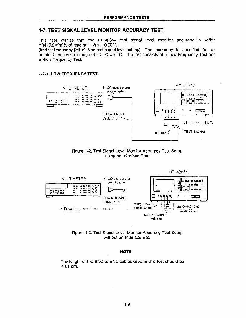
1-7. TEST SIGNAL LEVEL MONITOR ACCURACY TEST
This test verifies that the HP 4285A test signal level monitor accuracy is within ±[(4+O.2xfm)% of reading + Vm x 0.002]. (fm:test frequency [MHz], Vm: test signal level setting) The accuracy is specified for an ambient temperature range of 23 0 C ±5 0 C. The test consists of a Low Frequency Test and a High Frequency Test.
1· 7 -1. LOW FREQUENCY TEST
MULTIMETER BNC(f)-dual banana plug Adapter
o l::lI:JOOOCJ OClCOCJO
CO ecce o~t=1p---1 ~ ~ ~!;~~ OG oc cooo 000
BN C(m)-B N C(m) Cable 61 em ______
HP 4285A
D~OOOOOOO:
o ODD' OM 0 o 00000 o 0 DODD 0
o 0 I = I
INTERFACE BOX
DC BIAS TEST SIGNAL
Figure 1-2. Test Signal Level Monitor Accuracy Test Setup using an Interface Box
MULTIMETER
00
00
Cable 61 em
* Direct connection no cable
HP 4285A
I DII~ oo~oorn B 0 DOD lhJ o 10 01 DOD o 0 ~ODD 0
BNC(m)-BNC{m) Cable 30 em
Adapter
. o 0 I = I
BNC{m)-BNC{m) Cable 30 em
Figure 1-3. Test Signal Level Monitor Accuracy Test Setup without an Interface Box
NOTE
The length of the BNC to BNC cables used in this test should be ~ 61 em.
1·6
PERFORMANCE TESTS
EQUIPMENT:
Interface Box Multimeter BNC(m)-BNC(m) Cable, 61 cm BNC(f) to dual banana plug Adapter
PROCEDURE:
HP PN 04284-65007 HP 3458A HP PN 8120-1839 HP PN 1251-2277
1. Set up the equipment as shown in Figure 1-2.
NOTE
If the Interface Box is not available, use the following cables and adapters as a substitute. Figure 1-3 shows the test setup without the interface box.
BNC(m)-BNC(m) Cable, 30 cm Tee, BNC(m)(f)(f) Adapter
2. Set the multimeter as follows.
• ACV • Auto • SETACV SYNC • NPLC = 100
HP PN 8120-1838 2 ea. HP PN 1250-0781
3. Perform a SYSTEM RESET as described on page 1-4.
4. Press the MEAS SETUP MENU key and the 'CORRECTION' soft key to display the CORRECTION page.
5. Move the cursor to the CABLE field, and press the '0 m' softkey to set the cable length to 0 m.
6. Press the DISPLAY FORMAT MENU key to display the MEAS DISPLAY page.
7. Move the cursor to the FREQ field and set the test frequency to 100 kHz.
8. Record the multimeter reading into Calculation Sheet column [a], and calculate the test limits according to the calculation sheet.
9. Confirm that the Level Monitor reading (Vm) is within the specified test limits.
10. Perform the test for a" settings listed in Table 1-4 by repeating steps 7 to 9 for each listed setting.
1-7
PERFORMANCE TESTS
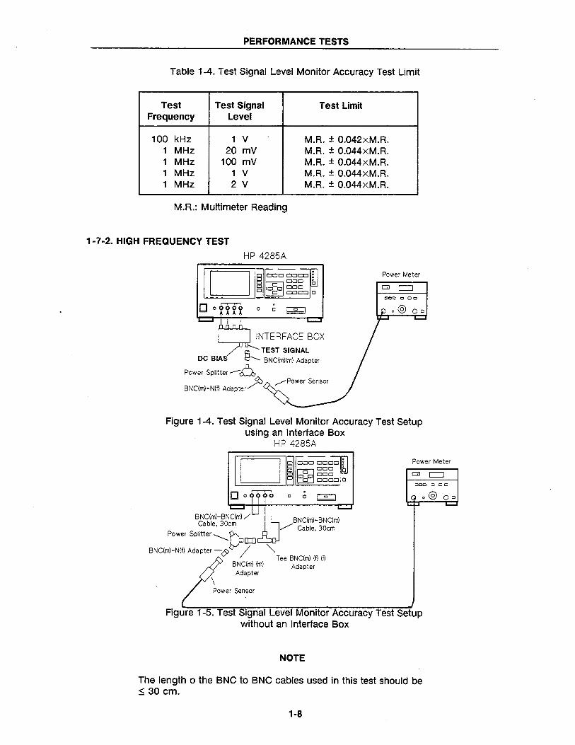
Table 1-4. Test Signal Level Monitor Accuracy Test Limit
Test Test Signal Test Limit Frequency Level
100 kHz 1 V M.R. ± 0.042xM.R. 1 MHz 20 mV M.R. ± 0.044xM.R. 1 MHz 100 mV M.R. ± 0.044xM.R. 1 MHz 1 V M.R. ± 0.044xM.R. 1 MHz 2 V M.R. ± 0.044xM.R.
M.R.: Multimeter Reading
1-7-2. HIGH FREQUENCY TEST
HP 4285A
I DI I~ oo~oo~: o OCiO' oM 0 o 0 CI 000 o 0 OCiOO 0
o 0 .
o 0 I = I
INTERFACE BOX '--~.,...J
TEST SIGNAL DC BIAS § ......... BNC(m)(m) Adapter
Power SPlitter-O ~ ........-Power Sensor
BNC(m)-N(f) Adapter./"
Power Meter
000 000
Figure 1-4. Test Signal Level Monitor Accuracy Test Setup using an Interface Box
HP 4285A
I DI I~ oCl~ClClIfl Cl OOCI lW 8 IOCIOI OOCI o CI OOCIO 0
BNC(m)-BNC(m) / Cable,30cm
Power SPlitter ............... r> BNC(m)-N(f) Adapter -& / ""
. o 0 I = I
BNC(m)-BNC(m) / Cable, 30cm
Tee BNC(m) (f) (f) BNC(m) (m) Adapter Adapter
\ Power Sensor
Power Meter
000 0 co
Figure 1-5. Test Signal Level Monitor Accuracy Test Setup without an Interface Box
NOTE
The length 0 the BNC to BNC cables used in this test should be :5 30 cm.
1-8
PERFORMANCE TESTS
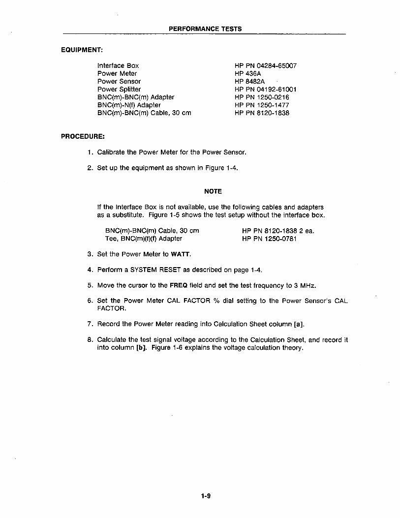
EQUIPMENT:
Interface Box Power Meter Power Sensor Power Splitter BNC(m)-BNC(m) Adapter BNC(m)-N(f) Adapter BNC(m)-BNC(m) Cable, 30 cm
PROCEDURE:
HP PN 04284-65007 HP 436A HP 8482A HP PN 04192-61001 HP PN 1250-0216 HP PN 1250-1477 HP PN 8120-1838
1. Calibrate the Power Meter for the Power Sensor.
2. Set up the equipment as shown in Figure 1-4.
NOTE
If the Interface Box is not available, use the following cables and adapters as a substitute. Figure 1-5 shows the test setup without the interface box.
BNC(m)-BNC(m) Cable, 30 cm Tee, BNC(m)(f)(f) Adapter
3. Set the Power Meter to WATT.
HP PN 8120-18382 ea. HP PN 1250-0781
4. Perform a SYSTEM RESET as described on page 1-4.
5. Move the cursor to the FREQ field and set the test frequency to 3 MHz.
6. Set the Power Meter CAL FACTOR % dial setting to the Power Sensor's CAL FACTOR.
7. Record the Power Meter reading into Calculation Sheet column [a].
8. Calculate the test signal voltage according to the Calculation Sheet, and record it into column [b]. Figure 1-6 explains the voltage calculation theory.
1-9
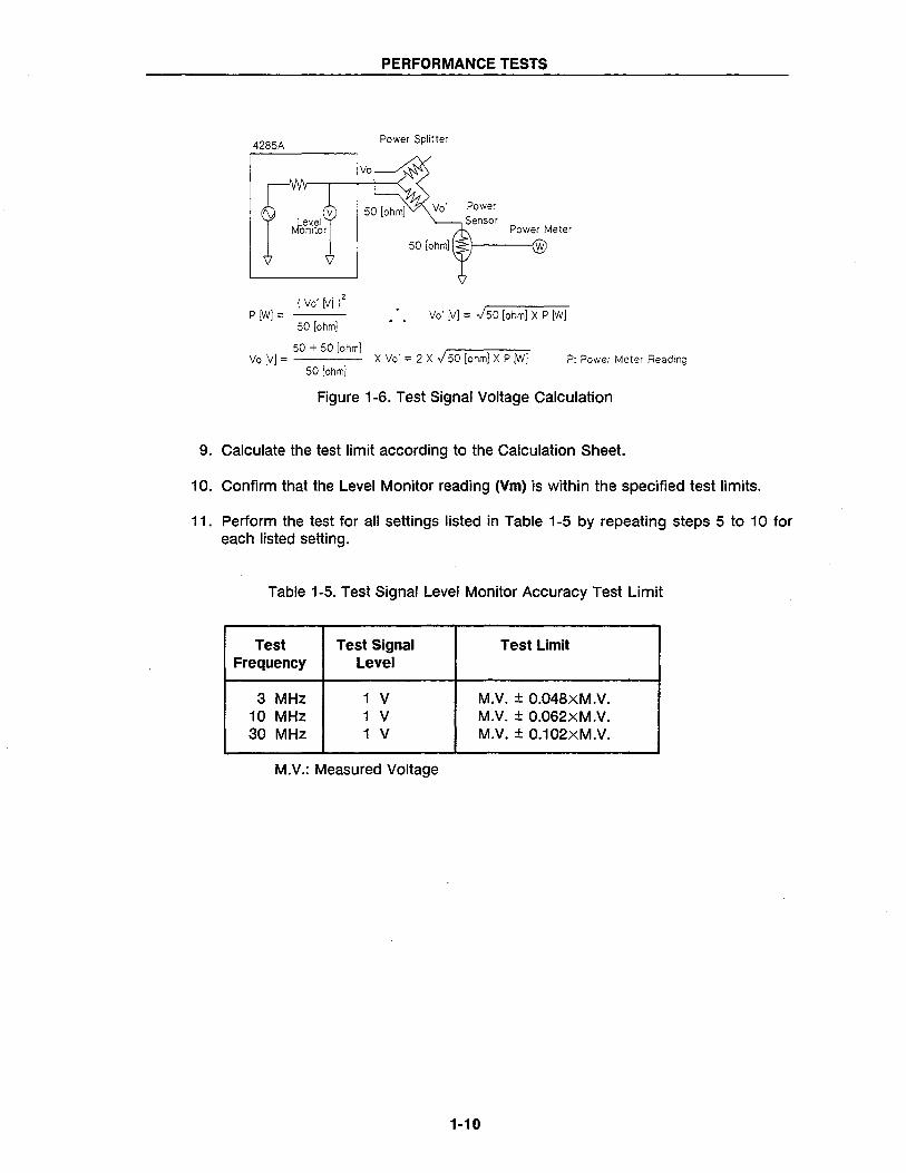
PERFORMANCE TESTS
Power Splitter
Vo' Power Sensor
P [w]::: Vo' (V] ::: J50 (ohm] X P [w] 50 [ohm]
50 + 50 [ohm] Vo [V] ::: X Vo' ::: 2 X J 50 (ohm] X P (w] P: Power Meter Reading
50 [ohm]
Figure 1-6. Test Signal Voltage Calculation
9. Calculate the test limit according to the Calculation Sheet.
10. Confirm that the Level Monitor reading (Vm) is within the specified test limits.
11. Perform the test for a" settings listed in Table 1-5 by repeating steps 5 to 10 for each listed setting.
Table 1-5. Test Signal Level Monitor Accuracy Test Limit
Test Test Signal Test Limit Frequency Level
3 MHz 1 V M.V. ± 0.048xM.V. 10 MHz 1 V M.V. ± 0.062xM.V. 30 MHz 1 V M.V. ± 0.102xM.V.
M.V.: Measured Voltage
1-10
PERFORMANCE TESTS
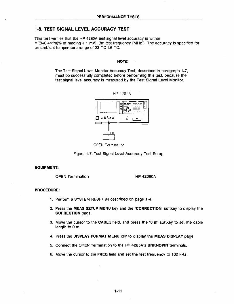
1-8. TEST SIGNAL LEVEL ACCURACY TEST
This test verifies that the HP 4285A test signal level accuracy is within ±[(8+O.4xfm)% of reading + 1 mY]. (fm:test frequency [MHz]) The accuracy is specified for an ambient temperature range of 23 0 C ±5 0 C.
NOTE
The Test Signal Level Monitor Accuracy Test, described in paragraph 1-7, must be successfully completed before performing this test, because the test signal level accuracy is measured by the Test Signal Level Monitor.
HP 4285A
D~ DOD DODD Ifl
B MDDD lhJ o 00000 o 0 DODD 0
o 00000 o
OPEN Termination
Figure 1-7. Test Signal Level Accuracy Test Setup
EQUIPMENT:
OPEN Termination HP 42090A
PROCEDURE:
1. Perform a SYSTEM RESET as described on page 1-4.
2. Press the MEAS SETUP MENU key and the 'CORRECTION' softkey to display the CORRECTION page.
3. Move the cursor to the CABLE field, and press the '0 m' softkey to set the cable length to 0 m.
4. Press the DISPLAY FORMAT MENU key to display the MEAS DISPLAY page.
5. Connect the OPEN Termination to the HP 4285A's UNKNOWN terminals.
6. Move the cursor to the FREQ field and set the test frequency to 100 kHz.
1-11
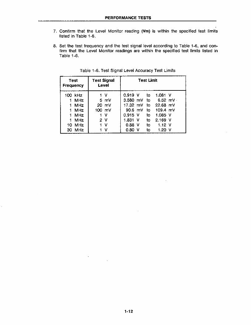
PERFORMANCE TESTS
7. Confirm that the Level Monitor reading (Vm) is within the specified test limits listed in Table 1-6.
8. Set the test frequency and the test signal level according to Table 1-6, and confirm that the Level Monitor readings are within the specified test limits listed in Table 1-6.
Table 1-6. Test Signal Level Accuracy Test Limits
Test Test Signal Test Limit Frequency Level
100 kHz 1 V 0.919 V to 1.081 V 1 MHz 5 mV 3.580 mV to 6.52 mV 1 MHz 20 mV 17.32 mV to 22.68 mV 1 MHz 100 mV 90.6 mV to 109.4 mV 1 MHz 1 V 0.915 V to 1.085 V 1 MHz 2 V 1.831 V to 2.169 V
10 MHz 1 V 0.88 V to 1.12 V 30 MHz 1 V 0.80 V to 1.20 V
1-12
PERFORMANCE TESTS
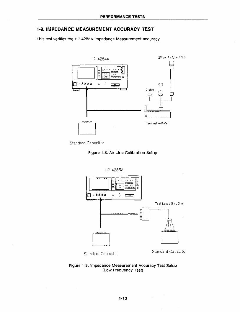
1-9. IMPEDANCE MEASUREMENT ACCURACY TEST
This test verifies the HP 4285A Impedance Measurement accuracy.
HP 4284A
o DOD DODD : Dr--~ B MODO 0 o 0 0 ~OD o 0 DODD 0
D 00000 . 0 0 I = I
L.-.-I L.-.-I
o Standard Capacitor
o ohm
CJ
I
20 em Air Line / 0 S
OS
g
1 o
Terminal Adapter
Figure 1-8. Air Line Calibration Setup
HP 4285A
D~ DOD OOOO~:
o ODD' OM 0 o 0 0 DOD o 0 DODD 0
o 0 OCi"Oo . o 0 I = I
Test Leads (1 m. 2 m)
o Standard Capacitor
Standard Capacitor
Figure 1-9. Impedance Measurement Accuracy Test Setup (Low Frequency Test)
1-13
PERFORMANCE TESTS
HP 4285A
Test Leads (1 m. 2 m)
g OS OS
20 em Air Line 20 em Air Line
Terminal Adapter Terminal Adapter
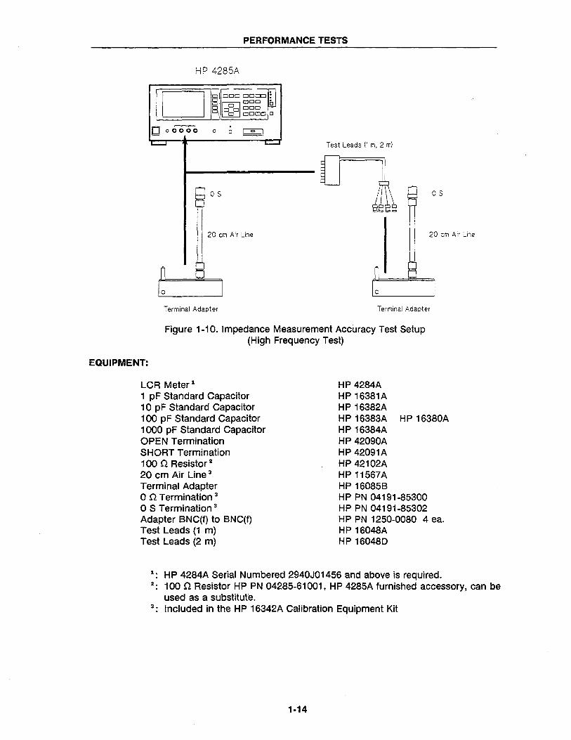
Figure 1-10. Impedance Measurement Accuracy Test Setup (High Frequency Test)
EQUIPMENT:
LCR Meter 1
1 pF Standard Capacitor 10 pF Standard Capacitor 100 pF Standard Capacitor 1000 pF Standard Capacitor OPEN Termination SHORT Termination 100 n Resistor 2
20 cm Air Line 3
Terminal Adapter on Termination 3
o S Termination 3
Adapter BNC(f) to BNC(f) Test Leads (1 m) Test Leads (2 m)
HP 4284A HP 16381A HP 16382A HP 16383A HP 16380A HP 16384A HP 42090A HP 42091A HP 42102A HP 11567A HP 160858 HP PN 04191-85300 HP PN 04191-85302 HP PN 1250-0080 4 ea. HP 16048A HP 160480
1. HP 4284A Serial Numbered 2940J01456 and above is required. 2. 100 n Resistor HP PN 04285-61001, HP 4285A furnished accessory, can be
used as a substitute. 3. Included in the HP 16342A Calibration Equipment Kit
1-14
PERFORMANCE TESTS
PROCEDURE:
NOTE
The Impedance Measurement Accuracy Test consists of the following seven blocks.
Air Line Calibration
o m Low Frequency Test
o m High Frequency Test
1 m Low Frequency Test
1 m High Frequency Test
2 m Low Frequency Test
2 m High Frequency Test
Air Line Calibration
Steps 1 to 27
Steps 28 to 45
Steps 46 to 61
Steps 62 to 76
Steps 77 to 86
Steps 87 to 101
Steps 102 to 111
1. Record the 10 pF Standard Capacitor's calibration value at 1 MHz into Calculation Sheet column [a].
2. Initialize the HP 4284A by performing a SYSTEM RESET. The HP 4285A SYSTEM RESET procedure shown on page 1-4 also applies to the HP 4284A.
3. Press the MEAS SETUP MENU key and the 'CORRECTION' soft key to display the CORRECTION page.
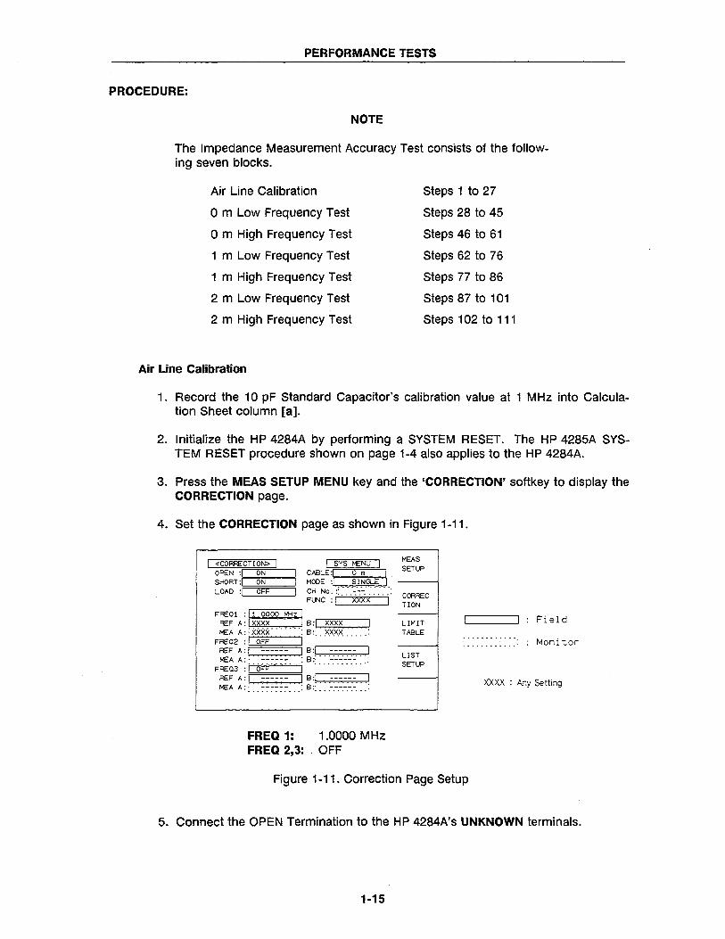
4. Set the CORRECTION page as shown in Figure 1-11.
I <CORRECT! ON> I I SYS I>£NU I OPEN :1 ON CABLE :1 0 m I SHORT:. ON MOCE :1 SINGLE i LOAD :)=1 =O~FF;;=~I CH NO.:'.·'- .--.--.--.' .- .- .- .- .-:
FUNC : I XXXX I FREOl : r::ll-'O""'OOO::-:::-:-MH:-:-z:-11
REF A:lxxxx 18:1 xxxx MEA A:: XXXX· -- -- --: 8:' XXXX .
FRE02 :, OFF " .......... .
REF A: I _nn_ , 8 :! ... -.-.-.-.-.-... ' I>£AA:' ------ :8:- :
FRE03 :j" OFF' .... --I ...... -- ... .
~~ ~;f: :~~~~~~:: :1 ~;f:: :=:=:=:=:=:=:: :1
FREQ 1: 1.0000 MHz FREQ 2,3: . OFF
MEAS SETUP
CORREC nON
LIMIT TABLE
LIST SETUP
Figure 1-11. Correction Page Setup
Field
Monitor
XXXX : Any Setting
5. Connect the OPEN Termination to the HP 4284A's UNKNOWN terminals.
1·15
PERFORMANCE TESTS
6. Move the cursor to the FREQ1 field, and press the 'MEAS OPEN' softkey to store the open correction data.
7. Connect the SHORT Termination to the HP 4284A's UNKNOWN terminals.
8. Press the 'MEAS SHORT' soft key to store the short correction data.
9. Press the MEAS SETUP MENU key to display the MEAS SETUP page.
10. Move the cursor to the FREQ field, and set the test frequency to 1.00000 MHz.
11. Move the cursor to the TRIG field, and press the 'MAN' softkey to set the trigger mode to manual.
12. Move the cursor to the AVG field, and press the 4 and ENTER keys to set the averaging rate to 4.
13. Press the DISPLAY FORMAT MENU key to display the MEAS DISPLAY page.
14. Connect the 10 pF Standard to the HP 4284A's UNKNOWN terminals.
15. Press the TRIGGER key.
16. Record the Cp reading into Calculation Sheet column [b].
17. Connect the Terminal Adapter (HP 16085B) to the HP 4284A's UNKNOWN terminals.
18. Press the MEAS SETUP MENU key and the 'CORRECTION' softkey to display the CORRECTION page.
19. Connect the 0 S Termination to the Terminal Adapter's OUTPUT terminal.
20. Move the cursor to the' FREQ1 field, and presS! the 'MEAS OPEN' softkey to store the OPEN correction data.
21. Connect the 0 n Termination to the Terminal Adapter's OUTPUT terminals.
22. Press the 'MEAS SHORT' softkey to store the short correction data.
23. Press the DISPLAY FORMAT MENU key to display the MEAS DISPLAY page.
24. Connect the 20 cm Air Line to the Terminal Adapter's OUTPUT terminal.
25. Connect the 0 S Termination to the 20 cm Air Line.
26. Press the TRIGGER key, and record the Cp reading into Calculation Sheet column [c]. .
27. Calculate the Air Line calibration value for 1 MHz, according to the Calculation Sheet.
1·16
PERFORMANCE TESTS
o m Low Frequency Test
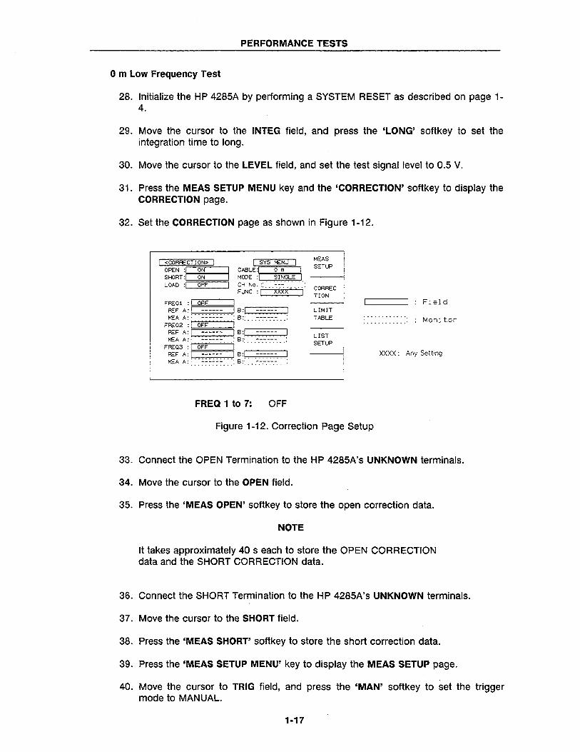
28. Initialize the HP 4285A by performing a SYSTEM RESET as described on page 1-4.
29. Move the cursor to the INTEG field, and press the 'LONG' softkey to set the integration time to long.
30. Move the cursor to the LEVEL field, and set the test signal level to 0.5 V.
31. Press the MEAS SETUP MENU key and the 'CORRECTION' softkey to display the CORRECTION page.
32. Set the CORRECTION page as shown in Figure 1-12.
I <CORRECTION> I I SYS MENU OREN :1 ON CABLE :1 0 m I SHORT:~O~N'----I MODE :1 .. SI!'I.GL.E J LOAD :1 OFF I CH No. :
FI..NC :rl ·:":"·'V·Xx';';·Xv-X'-'-· .-'-; ...
FREOl : '-1 =OF=F-----,I REF A: I ------ I B:I ------ I MEA A::·· :.:.:.:..:.: .... B:· ------ :
FRE02 : I OFF i· .......... . REF A: I ------ I B :1. .. -.. -.. -.-... I F:~3A ~ i· o;;~~~~· .. ; B:: ... -.-.-.-:-:: .. :
REF A: I ------ I B:I - --- I MEA A:: >.:.~:~~:::: B::: : :-:-:-:-:-:-:: ::
FREQ 1 to 7: OFF
MEAS SETUP
CORREC nON
LIMIT TABLE
LIST SETUP
Figure 1-12. Correction Page Setup
Field
Moni tor
XXXX: Any Setting
33. Connect the OPEN Termination to the HP 4285A's UNKNOWN terminals.
34. Move the cursor to the OPEN field.
35. Press the 'MEAS OPEN' softkey to store the open correction data.
NOTE
It takes approximately 40 s each to store the OPEN CORRECTION data and the SHORT CORRECTION data.
36. Connect the SHORT Termination to the HP 4285A's UNKNOWN terminals.
37. Move the cursor to the SHORT field.
38. Press the 'MEAS SHORT' softkey to store the short correction data.
39. Press the 'MEAS SETUP MENU' key to display the MEAS SETUP page.
40. Move the cursor to TRIG field, and press the 'MAN' softkey to set the trigger mode to MANUAL.
1-17
PERFORMANCE TESTS
41. Press the 'DISPLAY FORMAT MENU' key to display the MEAS DISPLAY page.
42. Connect the 1 pF Standard to the HP 4285A's UNKNOWN terminals.
43. Move the cursor to the LEVEL field, and set the test signal level to 5 mY.
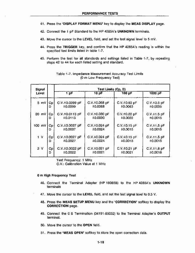
44. Press the TRIGGER key, and confirm that the HP 4285A's reading is within the specified test limits listed in table 1-7.
45. Perform the test for all standards and settings listed in Table 1-7, by repeating steps 42 to 44 for each listed setting and standard.
Signal Level
5 mV Cp 0
20 mV Cp 0
100 mV Cp 0
1 V Cp 0
2 V Cp 0
Table 1-7. Impedance Measurement Accuracy Test Limits (0 m Low Frequency Test)
Test Limits (Cp, D) 1 pF 10 pF 100 pF
C.V.±0.0399 pF C.V.±0.068 pF C.V.±0.63 pF ±0.0399 ±0.0068 ±0.0063
C.V.±0.0113 pF C.V.±0.030 pF C.V.±0.22 pF ±b.0113 ±0.0030 ±0.0022
C.V.±0.0037 pF C.V.±0.024 pF C.V.±0.15 pF ±0.0037 ±0.0024 ±0.0015
C.V.±0.0027 pF C.V.±0.024 pF C.V.±0.15 pF ±0.0027 ±0.0024 ±0.0015
C.V.±0.0022 pF C.V.±0.021 pF C.V.±0.21 pF ±0.0022 ±0.0021 ±0.0021
Test Frequency: 1 MHz C.V.: Calibration Value at 1 MHz
o m High Frequency Test
1000 pF
C.V.±3.5 pF ±0.0035
C.V.±1.5 pF ±0.0015
C.V.±1.5 pF ±0.0015
C.V.±1.5 pF ±0.0015
C.V.±1.8 pF ±0.0018
46. Connect the Terminal Adapter (HP 16085B) to the HP 4285A's UNKNOWN terminals
47. Move the cursor to the LEVEL field, and set the test signal level to 0.5 V.
48. Press the MEAS SETUP. MENU key and the 'CORRECTION' softkey to display the CORRECTION page.
49. Connect the 0 S Termination (04191-85032) to the Terminal Adapter's OUTPUT terminal.
50. Move the cursor to the OPEN field.
51. Press the 'MEAS OPEN' softkey to store the open correction data.
1·18
PERFORMANCE TESTS
52. Connect the 0 n Termination (04191-85030) to the Terminal Adapter's OUTPUT terminal.
53. Move the cursor to the SHORT field.
54. Press the 'MEAS SHORT' softkey to store the short correction data.
55. Press the 'DISPLAY FORMAT MENU' key to display the MEAS DISPLAY page.
56. Connect the 20 cm Air Line to the Terminal Adapter's OUTPUT terminal.
57. Connect the 0 S Termination to the 20 cm Air Line.
58. Move the cursor to LEVEL field, and set the test signal level to 1 V.
59. Move the cursor to FREQ field, and set the test frequency to 1.1 MHz.
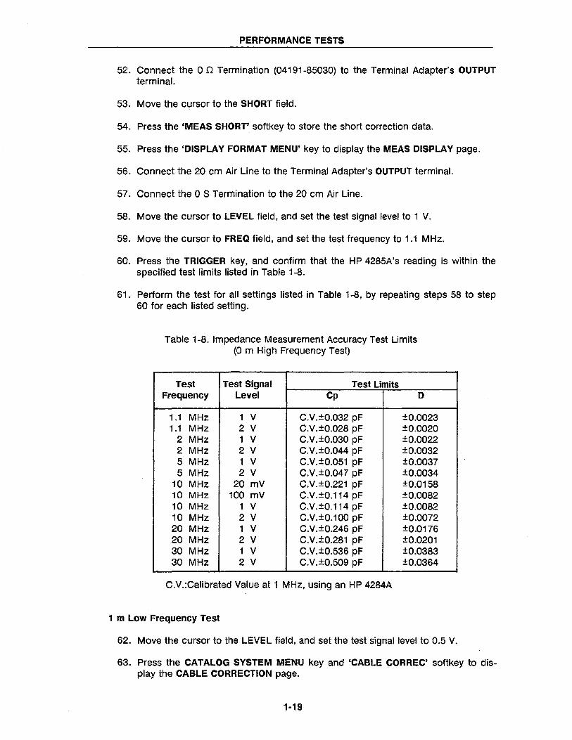
60. Press the TRIGGER key, and confirm that the HP 4285A's reading is within the specified test limits listed in Table 1-8.
61. Perform the test for all settings listed in Table 1-8, by repeating steps 58 to step 60 for each listed setting.
Table 1-8. Impedance Measurement Accuracy Test Limits (0 m High Frequency Test)
Test Test Signal Test Limits Frequency Level Cp D
1.1 MHz 1 V C.V.±0.032 pF ±0.0023 1.1 MHz 2 V C.V.±0.028 pF ±0.0020
2 MHz 1 V C.V.±0.030 pF ±0.0022 2 MHz 2 V C.V.±0.044 pF ±0.0032 5 MHz 1 V C.V.±0.051 pF ±0.0037 5 MHz 2 V C.V.±0.047 pF ±0.0034
10 MHz 20 mV C.V.±0.221 pF ±0.0158 10 MHz 100 mV C.V.±0.114 pF ±0.0082 10 MHz 1 V C.V.±0.114 pF ±0.0082 10 MHz 2 V C.V.±0.100 pF ±0.0072 20 MHz 1 V C.V.±0.246 pF ±0.0176 20 MHz 2 V C.V.±0.281 pF ±0.0201 30 MHz 1 V C.V.±0.536 pF ±0.0383 30 MHz 2 V C.V.±0.509 pF ±0.0364
C.V.:Calibrated Value at 1 MHz, using an HP 4284A
1 m Low Frequency Test
62. Move the cursor to the LEVEL field, and set the test signal level to 0.5 V.
63. Press the CATALOG SYSTEM MENU key and 'CABLE CORREC' softkey to display the CABLE CORRECTION page.
1·19
PERFORMANCE TESTS
64. Move the cursor to CABLE CORRECTION MENU field.
65. Press the 1 and ENTER keys to start the 1 m Cable Correction.
66. Perform the 1 m Cable Correction according to the instruction on the HP 4285A's LCD.
67. Press the MEAS SETUP MENU key and the 'CORRECTION' softkey to display the CORRECTION page.
68. Move the cursor to CABLE field, and press the '1 m' softkey to set the cable length to 1 m.
69. Connect the 1 m Test Leads (HP 16048A) to the UNKNOWN terminals.
70. Store the OPEN CORRECTION data and the SHORT CORRECTION data, refer to steps 33 to 38. In this procedure the OPEN termination and the SHORT termination should be connected to the 1 m Test Leads (HP 16048A) with 4 BNC(f)BNC(f) adapters.
71. Press the 'DISPLAY FORMAT MENU' key to display the MEAS DISPLAY page.
72. Connect the 100 pF Standard to the 1 m Test Leads.
73. Move the cursor to the LEVEL field, and set the test signal level to 1 V.
74. Move the cursor to the FREQ field, and set the test frequency to 1 MHz.
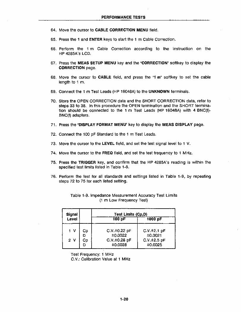
75. Press the TRIGGER key, and confirm that the HP 4285A's reading is within the specified test limits listed in Table 1-9.
76. Perform the test for all standards and settings listed in Table 1-9, by repeating steps 72 to 75 for each listed setting.
Table 1-9. Impedance Measurement Accuracy Test Limits (1 m Low Frequency Test)
Signal Test Limits (Cp,D) Level 100 pF 1000 pF
1 V Cp C.V.±0.22 pF C.V.±2.1 pF D ±0.0022 ±0.0021
2 V Cp C.V.±0.28 pF C.V.±2.5 pF D ±0.0028 ±0.0025
Test Frequency: 1 MHz C.V.: Calibration Value at 1 MHz
1-20
PERFORMANCE TESTS
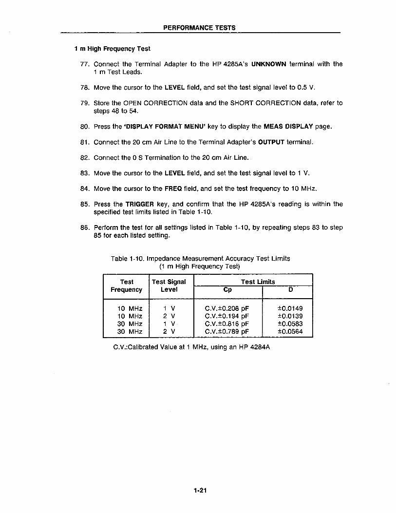
1 m High Frequency Test
77. Connect the Terminal Adapter to the HP 4285A's UNKNOWN terminal with the 1 m Test Leads.
78. Move the cursor to the LEVEL field, and set the test signal level to 0.5 V.
79. Store the OPEN CORRECTION data and the SHORT CORRECTION data, refer to steps 48 to 54.
80. Press the 'DISPLAY FORMAT MENU' key to display the MEAS DISPLAY page.
81. Connect the 20 cm Air Line to the Terminal Adapter's OUTPUT terminal.
82. Connect the 0 S Termination to the 20 cm Air Line.
83. Move the cursor to the LEVEL field, and set the test signal level to 1 V.
84. Move the cursor to the FREQ field, and set the test frequency to 10 MHz.
85. Press the TRIGGER key, and confirm that the HP 4285A's reading is within the specified test limits listed in Table 1-10.
86. Perform the test for all settings listed in Table 1-10, by repeating steps 83 to step 85 for each listed setting.
Table 1-10. Impedance Measurement Accuracy Test Limits (1 m High Frequency Test)
Test Test Signal Test Limits Frequency Level Cp D
10 MHz 1 V C.V.±0.208 pF ±0.O149 10 MHz 2 V C.V.±0.194 pF ±O.O139 30 MHz 1 V C.V.±0.816 pF ±0.O583 30 MHz 2 V C.V.±0.789 pF ±0.O564
C.V.:Calibrated Value at 1 MHz, using an HP 4284A
1-21
PERFORMANCE TESTS
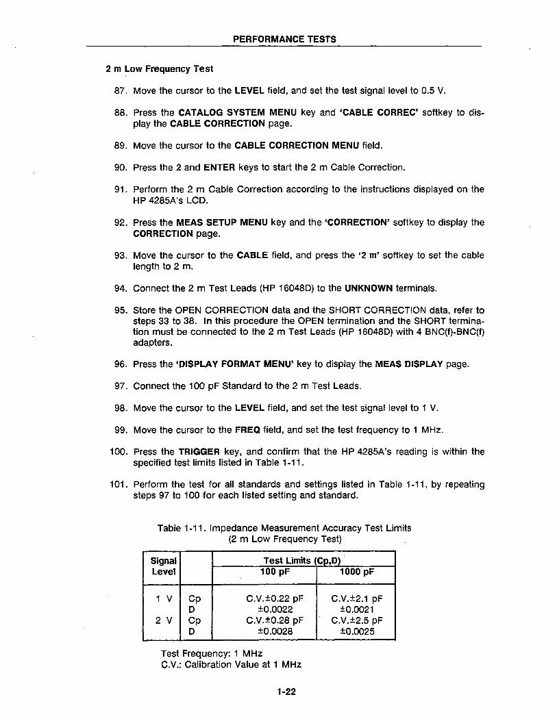
2 m Low Frequency Test
87. Move the cursor to the LEVEL field, and set the test signal level to 0.5 V.
88. Press the CATALOG SYSTEM MENU key and 'CABLE CORREC' softkey to display the CABLE CORRECTION page.
89. Move the cursor to the CABLE CORRECTION MENU field.
90. Press the 2 and ENTER keys to start the 2 m Cable Correction.
91. Perform the 2 m Cable Correction according to the instructions displayed on the HP 4285A's LCD.
92. Press the MEAS SETUP MENU key and the 'CORRECTION' softkey to display the CORRECTION page.
93. Move the cursor to the CABLE field, and press the '2 m' softkey to set the cable length to 2 m.
94. Connect the 2 m Test Leads (HP 16048D) to the UNKNOWN terminals.
95. Store the OPEN CORRECTION data and the SHORT CORRECTION data, refer to steps 33 to 38. In this procedure the OPEN termination and the SHORT termination must be connected to the 2 m Test Leads (HP 16048D) with 4 BNC(f)-BNC(f) adapters.
96. Press the 'DISPLAY FORMAT MENU' key to display the MEAS DISPLAY page.
97. Connect the 100 pF Standard to the 2 m Test Leads.
98. Move the cursor to the LEVEL field, and set the test signal level to 1 V.
99. Move the cursor to the FREQ field, and set the test frequency to 1 MHz.
100. Press the TRIGGER key, and confirm that the HP 4285A's reading is within the specified test limits listed in Table 1-11.
101. Perform the test for all standards and settings listed in Table 1-11, by repeating steps 97 to 100 for each listed setting and standard.
Table 1-11. Impedance Measurement Accuracy Test Limits (2 m Low Frequency Test)
Signal Test Limits (Cp,D) Level 100 pF 1000 pF
1 V Cp C.V.±0.22 pF C.V.±2.1 pF D ±0.0022 ±0.0021
2 V Cp C.V.±0.28 pF C.V.±2.5 pF D ±0.0028 ±0.0025
Test Frequency: 1 MHz C.V.: Calibration Value at 1 MHz
1-22
PERFORMANCE TESTS
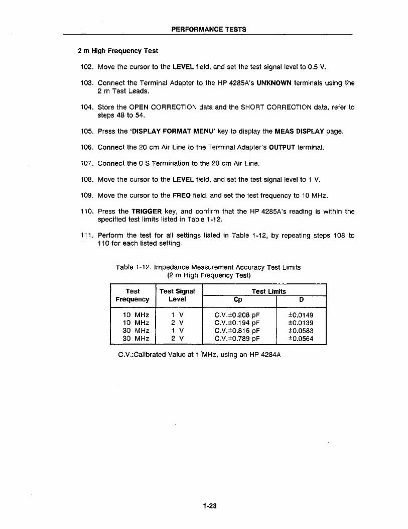
2 m High Frequency Test
102. Move the cursor to the LEVEL field, and set the test signal level to 0.5 V.
103. Connect the Terminal Adapter to the HP 4285A's UNKNOWN terminals using the 2 m Test Leads.
104. Store the OPEN CORRECTION data and the SHORT CORRECTION data, refer to steps 48 to 54.
105. Press the 'DISPLAY FORMAT MENU' key to display the MEAS DISPLAY page.
106. Connect the 20 cm Air Line to the Terminal Adapter's OUTPUT terminal.
107. Connect the 0 S Termination to the 20 cm Air Line.
108. Move the cursor to the LEVEL field, and set the test signal level to 1 V.
109. Move the cursor to the FREQ field, and set the test frequency to 10 MHz.
110. Press the TRIGGER key, and confirm that the HP 4285A's reading is within the specified test limits listed in Table 1-12.
111. Perform the test for all settings listed in Table 1-12, by repeating steps 108 to 110 for each listed setting.
Table 1-12. Impedance Measurement Accuracy Test Limits (2 m High Frequency Test)
Test Test Signal Test Limits Frequency Level Cp D
10 MHz 1 V C.V.±0.208 pF ±0.0149 10 MHz 2 V C.V.±0.194 pF ±0.0139 30 MHz 1 V C.V.±0.816 pF ±0.0583 30 MHz 2 V C.V.±0.789 pF ±0.0564
C.V.:Calibrated Value at 1 MHz, using an HP 4284A
1-23
PERFORMANCE TESTS
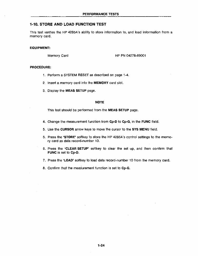
1-10. STORE AND LOAD FUNCTION TEST
This test verifies the HP 4285A's ability to store information to, and load information from a memory card.
EQUIPMENT:
Memory Card HP PN 04278-89001
PROCEDURE:
1. Perform a SYSTEM RESET as described on page 1-4.
2. Insert a memory card into the MEMORY card slot.
3. Display the MEAS SETUP page.
NOTE
This test should be performed from the MEAS SETUP page.
4. Change the measurement function from Cp-D to Cp-G, in the FUNC field.
5. Use the CURSOR arrow keys to move the cursor to the SYS MENU field.
5. Press the 'STORE' softkey to store the HP 4285A's control settings to the memory card as data record-number 10.
6. Press the 'CLEAR SETUP' softkey to clear the set up, and then confirm that FUNC is set to Cp-D.
7. Press the 'LOAD' softkey to load data record-number 10 from the memory card.
8. Confirm that the measurement function is set to Cp-G.
1-24
PERFORMANCE TESTS
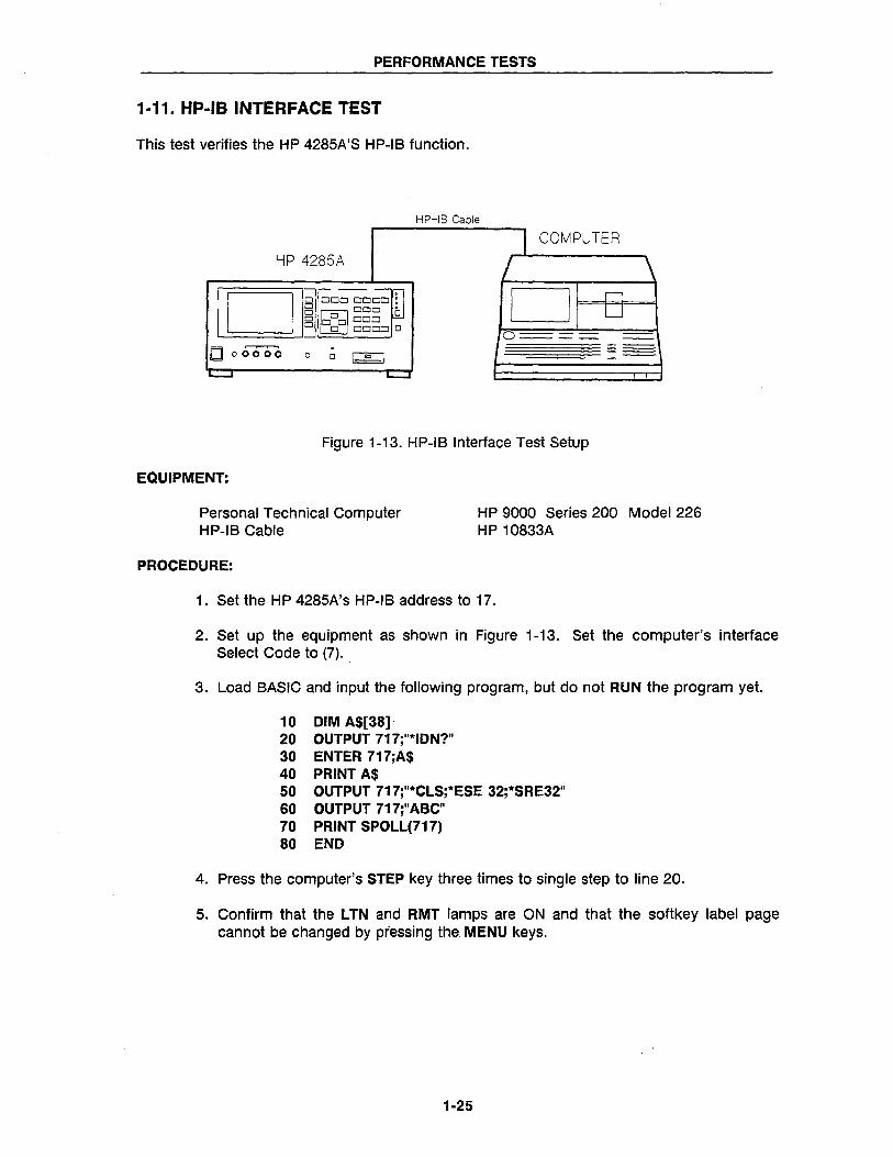
1-11. HP-IB INTERFACE TEST
This test verifies the HP 4285A'S HP-IB function.
HP-IB Cable
HP 4285A J COMPUTER
/
D~~o~~~ 0 n D DOD. U D~ 0 BOD ODo
D 00= 0 0---_ --o 00000 0 0 I Q I
~ ~
Figure 1-13. HP-IB Interface Test Setup
EQUIPMENT:
Personal Technical Computer HP-IB Cable
HP 9000 Series 200 Model 226 HP 10833A
PROCEDURE:
1. Set the HP 4285A's HP-IB address to 17.
2. Set up the equipment as shown in Figure 1-13. Set the computer's interface Select Code to (7).
3. Load BASIC and input the following program, but do not RUN the program yet.
10 DIM A$[38] 20 OUTPUT 717;"*IDN?" 30 ENTER 717;A$ 40 PRINT A$ 50 OUTPUT 717;"*CLS;*ESE 32;*SRE32" 60 OUTPUT 717;"ABC" 70 PRINT SPOLL(717) 80 END
4. Press the computer's STEP key three times to single step to line 20.
5. Confirm that the L TN and RMT lamps are ON and that the softkey label page cannot be changed by pressing the MENU keys.
1-25
PERFORMANCE TESTS
6. Press the H P 4285A LCL key.
7. Confirm that the LTN lamp stays ON, the RMT lamp is OFF, and the soft key label page can be changed by pressing the MENU keys.
8. Press the computer's STEP key to execute line 30 and confirm that the TLK lamp is ON.
9. Step to line 40 and confirm that the following message is displayed on the computer.
"HEWLETT -PACKARD,4285A,O,REV01.00"
10. Step to line 60, and confirm that the SRQ, LTN, and RMT lamps are ON.
11. Step to line 80 and confirm that the status byte value displayed on the computer is greater than 95.
1-26
PERFORMANCE TESTS
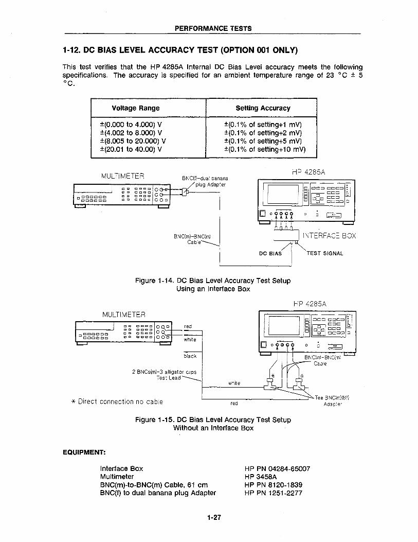
1-12. DC BIAS LEVEL ACCURACY TEST (OPTION 001 ONLY)
This test verifies that the HP 4285A Internal DC Bias Level accuracy meets the following specifications. The accuracy is specified for an ambient temperature range of 23 ° C ± 5 °C.
Voltage Range Setting Accuracy
±(O.OOO to 4.000) V ±(0.1 % of setting+1 mY) ±(4.002 to 8.000) V ±(0.1 % of setting+2 mY) ±(8.005 to 20.000) V ±(0.1 % of setting+5 mY) ±(20.01 to 40.00) V ±(0.1 % of setting+ 10 mY)
HP 4285A MULTIMETER BNC(f}-dual banana plug Adapter liD I~ ClCl~OCl ffl 0°00000
CJOOCJCJD
o Q 0 c:::t 0 0 0 G-e-f---r:I( ~ ~ ~ ~ ~:; 0 G.-.J.-·...[jJ--.--i cO 00,0 c 00 a
BN C(m)-B NC(rn) Cable '-----n-rr
DC BIAS
B ~ooo [J o 00000 o 0 DODD 0
o o I = I
INTERFACE BOX
TEST SIGNAL
Figure 1-14. DC Bias Level Accuracy Test Setup Using an Interface Box
MULTIMETER
I cc cc
o ClOClOCJO cc 000000 cc
......... white
OCOc::J OQCl ccoc OOco Ou.. 0000 000
red
~
black
2 BNCs(m)-3 alligator clips Test Lead ___
* Direct connection no cable
white
red
HP 4285A
Dj ClOCl ~ODD ffl B MODO [J o 0 oOOCl o 0 ~ODD 0
CJ o~ o o I = I
Tee BNC(m)(f)(f) Adapter
Figure 1-15. DC Bias Level Accuracy Test Setup Without an Interface Box
EQUIPMENT:
Interface Box Multimeter BNC(m)-to-BNC(m) Cable, 61 cm BNC(f) to dual banana plug Adapter
1·27
HP PN 04284-65007 HP 3458A HP PN 8120-1839 HP PN 1251-2277
PERFORMANCE TESTS
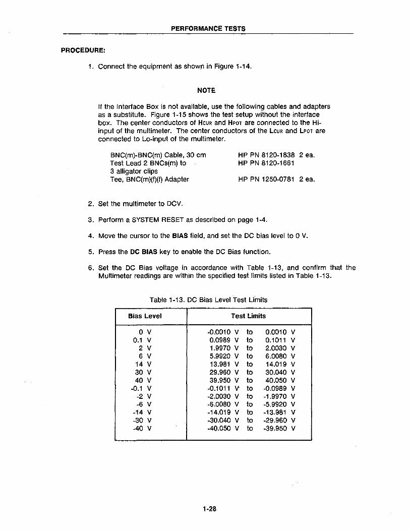
PROCEDURE:
1. Connect the equipment as shown in Figure 1-14.
NOTE
If the Interface Box is not available, use the following cables and adapters as a substitute. Figure 1-15 shows the test setup without the interface box. The center conductors of HeuR and HpOT are connected to the Hiinput of the multimeter. The center conductors of the LeuR and LpOT are connected to Lo-input of the multimeter.
BNC(m)-BNC(m) Cable, 30 cm Test Lead 2 BNCs(m) to 3 alligator clips Tee, BNC(m)(f)(f) Adapter
2. Set the multimeter to DCV.
HP PN 8120-1838 2 ea. HP PN8120-1661
HP PN 1250-0781 2 ea.
3. Perform a SYSTEM RESET as described on page 1-4.
4. Move the cursor to the BIAS field, and set the DC bias level to 0 V.
5. Press the DC BIAS key to enable the DC Bias function.
6. Set the DC Bias voltage in accordance with Table 1-13, and confirm that the Multimeter readings are within the specified test limits listed in Table 1-13.
Table 1-13. DC Bias Level Test Limits
Bias Level Test Limits
o V -0.0010 V to 0.0010 V 0.1 V 0.0989 V to 0.1011 V
2 V 1.9970 V to 2.0030 V 6 V 5.9920 V to 6.0080 V
14 V 13.981 V to 14.019 V 30 V 29.960 V to 30.040 V 40 V 39.950 V to 40.050 V
-0.1 V -0.1011 V to -0.0989 V -2 V -2.0030 V to -1.9970 V -6 V -6.0080 V to -5.9920 V
-14 V -14.019 V to -13.981 V -30 V -30.040 V to -29.960 V -40 V -40.050 V to -39.950 V
1·28
PERFORMANCE TESTS
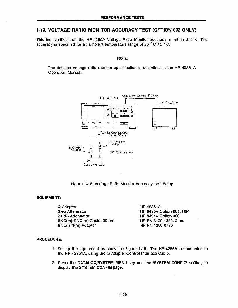
1-13. VOLTAGE RATIO MONITOR ACCURACY TEST (OPTION 002 ONLY)
This test verifies that the HP 4285A voltage Ratio Monitor accuracy is within ± 1 %. The accuracy is specified for an ambient temperature range of 23 0 C ±5 0 C.
NOTE
The detailed voltage ratio monitor specification is described in the HP 42851A Operation Manual.
HP 4285A Accessory Control IF Cable
I DI I~ oo~oo fI 8 M 000 lkJ o 0 0 CJCJ CJ o 0 CJCJoo 0
o o~ 0 0 I = I
BNC(m)-BNC(m) Cable. 30 cm
BNC(f}-N(m) .0. _____ Adapter
BNCIf}-N(m) ~ Adapter ~ A 8-
-u 20 dB Attenuator
d=J Step Attenuator
HP 42851A
D
Figure 1-16. Voltage Ratio Monitor Accuracy Test Setup
EQUIPMENT:
Q Adapter Step Attenuator 20 dB Attenuator BNC(m)-BNC(m) Cable, 30 cm BNC(f)-N(m) Adapter
PROCEDURE:
HP 42851A HP 8495A Option 001, H04 HP 8491A Option 020 HP PN 8120-1838, 2 ea. HP PN 1250-0780
1. Set up the equipment as shown in Figure 1-16. The H P 4285A is connected to the HP 42851A, using the Q Adapter Control Interface Cable.
2. Press the CATALOG/SYSTEM MENU key and the 'SYSTEM CONFIG' softkey to display the SYSTEM CON FIG page.
1-29
PERFORMANCE TESTS
3. Move the cursor to the CONFIG field, and press the 'Q Adapter' softkey to set the H P 4285A to Q measurement mode.
4. Perform a SYSTEM RESET as described on page 1-4.
5. Press the MEAS SETUP MENU key to display the MEAS SETUP page.
6. Move the cursor and set the HP 4285A as follows.
FREQ: TUNE: LEVEL: TRIG:
1 MHz FIX-C 150 mV MAN
7. Press the DISPLAY FORMAT MENU key to display the MEAS DISPLAY page.
8. Set the step attenuator to 0 dB.
9. Press the TRIGGER key, and record the Level Monitor Reading (V) in Calculation Sheet column [Vo].
NOTE
While in the Q measurement mode, the level monitor indicates approximately 60 times the value of the input voltage.
10. Set the step attenuator to 20 dB.
11. Record the Level Monitor Reading (V) in Calculation Sheet column [V20).
12. Calculate the measured value 20 LOG(VO/V20), and confirm the value is within the following specified test limits.
C.V. ± 0.086 [dB]
C.V.:Step Attenuator 20 dB Calibration value at 1 MHz
13. Press the CATALOG/SYSTEM MENU key and the 'SYSTEM CONFIG' softkey to display the SYSTEM CON FIG page.
14. Move the cursor to the CON FIG field, and press the 'OFF' softkey to set the HP 4285A to Impedance measurement mode.
1-30
PERFORMANCE TESTS
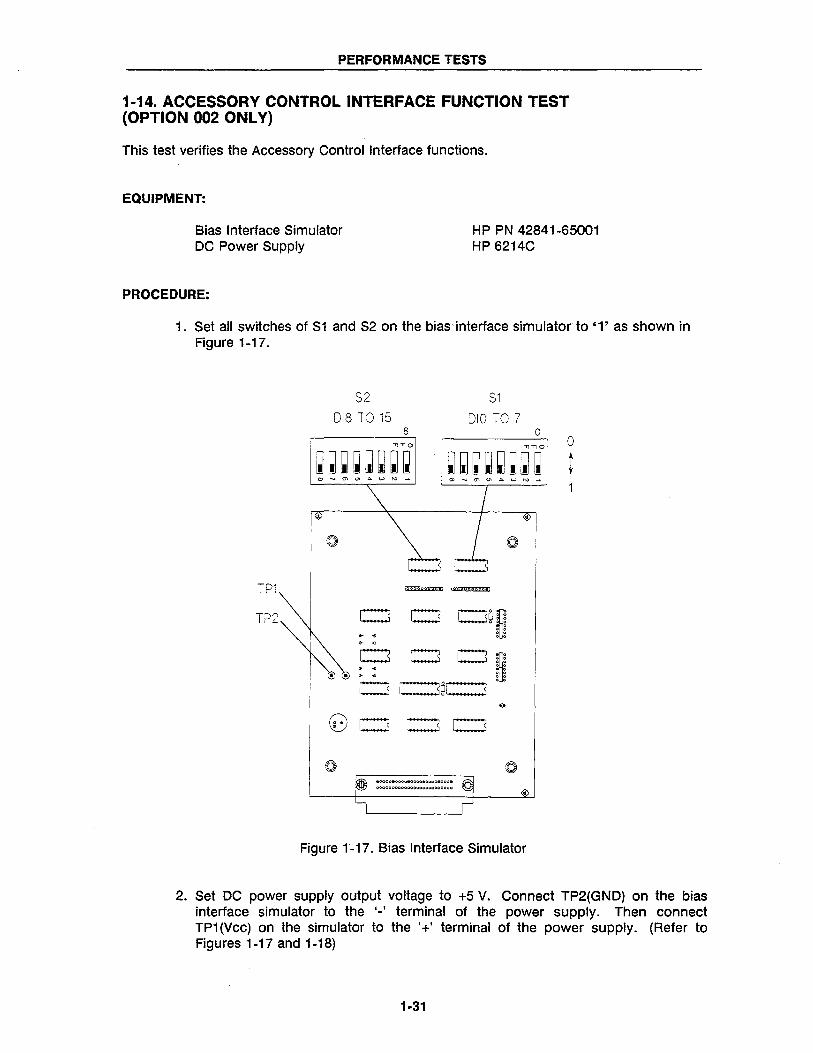
1-14. ACCESSORY CONTROL INTERFACE FUNCTION TEST (OPTION 002 ONLY)
This test verifies the Accessory Control Interface functions.
EQUIPMENT:
Bias Interface Simulator DC Power Supply
HP PN 42841-65001 HP 6214C
PROCEDURE:
1. Set all switches of S1 and S2 on the bias interface simulator to '1' as shown in Figure 1-17.
TP1
TP2
S2
DI8 TO 15 8
-"-"0
S1
DIO TO 7 o
-"-"0
~~~~~~~~ ~~~~~~~~
CJ CJ~O
®®~~OC~O
.00011.OO0".0000.oOQoeooo.
000000000000;>0000000000000
Figure 1"-17. Bias Interface Simulator
o
t
2. Set DC power supply output voltage to +5 V. Connect TP2(GND) on the bias interface simulator to the '-' terminal of the power supply. Then connect TP1(Vcc) on the simulator to the '+' terminal of the power supply. (Refer to Figures 1-17 and 1-18)
1-31
PERFORMANCE TESTS
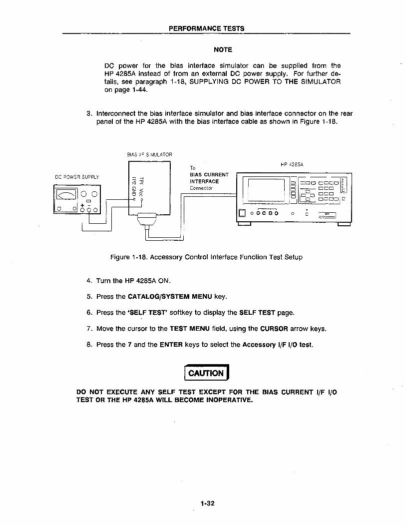
NOTE
DC power for the bias interface simulator can be supplied from the HP 4285A instead of from an external DC power supply. For further details, see paragraph 1-18, SUPPLYING DC POWER TO THE SIMULATOR on page 1-44.
3. Interconnect the bias interface simulator and bias interface connector on the rear panel of the HP 4285A with the bias interface cable as shown in Figure 1-18.
BIAS IIF SIMULATOR
DC POWER SUPPLY
To BIAS CURRENT INTERFACE Connector
HP 4285A
I DI I~ DOD DDDD~: o DOD' OM 0 o 00000 o 0 DODD 0
Do~ o
Figure 1-18. Accessory Control I nterface Function Test Setup
4. Turn the HP 4285A ON.
5. Press the CATALOG/SYSTEM MENU key.
6. Press the 'SELF TEST' softkey to display the SELF TEST page.
7. Move the cursor to the TEST MENU field, using the CURSOR arrow keys.
8. Press the 7 and the ENTER keys to select the Accessory I/F I/O test.
I CAUTION I DO NOT EXECUTE ANY SELF TEST EXCEPT FOR THE BIAS CURRENT I/F I/O TEST OR THE HP 4285A WILL BECOME INOPERATIVE.
1-32
PERFORMANCE TESTS
9. Press the 'TEST START' softkey.
NOTE
Check the settings of S1 and S2 described in the Step 1, if the HP 4285A's LCD displays "E74:lIlegal test setup".
10. Confirm that the /RESET LED on the bias interface simulator turns ON.
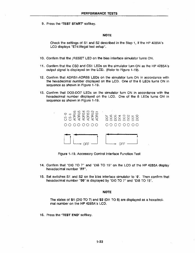
11. Confirm that the CSO and CS1 LEOs on the simulator turn ON as the HP 4285A's output signal is displayed on the LCD. (Refer to Figure 1-19).
12. Confirm that AORS1-AORS6 LEOs on the simulator turn ON in accordance with the hexadecimal number displayed on the LCD. One of the 6 LEOs turns ON in sequence as shown in Figure 1-19.
13. Confirm that 000-007 LEOs on the simulator turn ON in accordance with the hexadecimal number displayed on the LCD. One of the 8 LEOs turns ON in sequence as shown in Figure 1-19.
<.0 LD -<::t. 0) ·N .,..... o..-(/)(/)(/)(/)(/)(/)
I I ecececececec (/)(/)000000 00««««««
00000000
r---<..OlO'<j" (Y)N..-O 00000000 00000000
00000000
Figure 1-19. Accessory Control I nterface Function Test
14. Confirm that "010 TO 7" and "018 TO 15" on the LCD of the HP 4285A display hexadecimal number "FF".
15. Set switches S1 and S2 on the bias interface simulator to '0'. Then confirm that hexadecimal number "00" is displayed by "010 TO 7" and "018 TO 15".
NOTE
The states of S1 (010 TO 7) and S2 (011 TO 8) are displayed as a hexadecimal number on the HP 4285A's LCD.
16. Press the 'TEST END' softkey.
1-33
PERFORMANCE TESTS
1-15. HANDLER INTERFACE FUNCTION TEST (OPTION 201 ONLY)
Perform this test only when troubleshooting the Option 201 Handler Interface Board.
This test verifies the Option 201 handler interface functions.
EQUIPMENT:
Handler Simulator HP PN 04278-65001
PROCEDURE:
1. Disconnect the power cable from the HP 4285A and allow enough time (a few minutes), for the internal capacitors to discharge.
I WARNING I DANGEROUS ENERGY /VOLT AGE EXISTS WHEN THE HP 4285A IS IN OPERATION, AND FOR A TIME AFTER IT IS POWERED DOWN. ALLOW A FEW MINUTES FOR THE INTERNAL CAPACITORS TO DISCHARGE.
2. Disconnect the two rear feet which lock the top cover and rear panel together.
3. Fully loosen the top cover retaining screws located on the rear of the top cover.
4. Slide the top cover toward rear and lift it off. The top shield plate will be visible.
5. Remove the top shield plate to expose the PC boards.
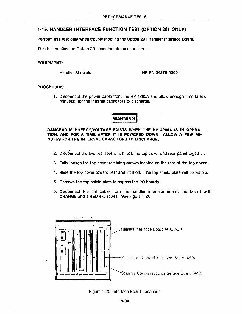
6. Disconnect the flat cable from the handler interface board, the board with ORANGE and a RED extractors. See Figure 1-20.
0 0
J ~ V ~
t---
-' 0 I='
Handler Interface Board (A30/A31)
3
[J . 0 . -I- 0
Accessory Control Interface Board (A50)
0
'-
~ n J""LJ"'L1"1.~
I Scanner Compensation/Interface Board (A40)
Figure 1-20. Interface Board Locations
1-34
PERFORMANCE TESTS
7. Remove the handler interface board.
NOTE
Before performing step 8, make a note of the jumper settings so that you can return them to their original settings after you finish this test.
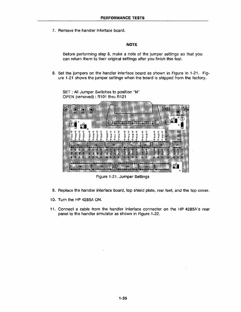
8. Set the jumpers on the handler interface board as shown in Figure in 1-21. Figure 1-21 shows the jumper settings when the board is shipped from the factory.
SET: All Jumper Switches to position "N" OPEN (removed) : R101 thru R121
Figure 1-21. Jumper Settings
9. Replace the handler interface board, top shield plate, rear feet, and the top cover.
10. Turn the HP 4285A ON.
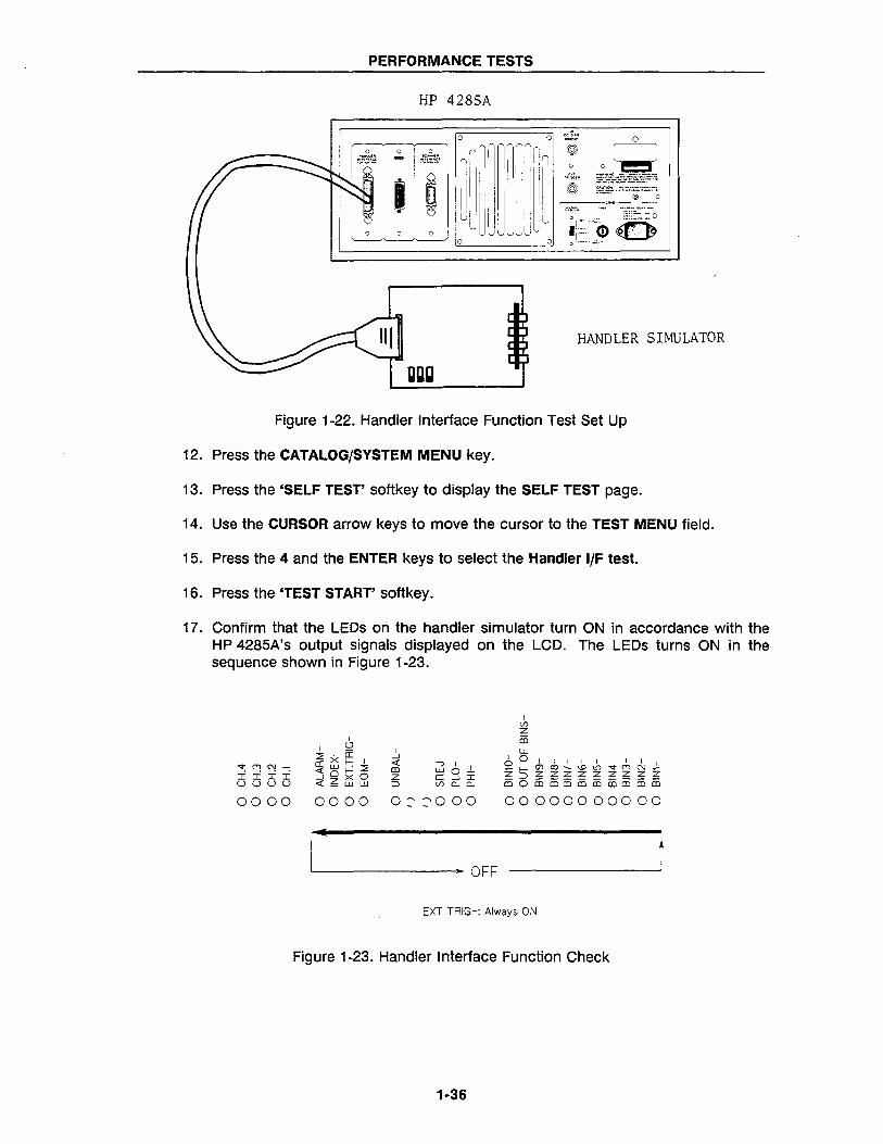
11. Connect a cable from the handler interface connector on the HP 4285A's rear panel to the handler simulator as shown in Figure 1-22.
1-35
PERFORMANCE TESTS
HP 4285A
HANDLER SIMULATOR
ggg
Figure 1-22. Handler Interface Function Test Set Up
12. Press the CATALOG/SYSTEM MENU key.
13. Press the 'SELF TEST' softkey to display the SELF TEST page.
14. Use the CURSOR arrow keys to move the cursor to the TEST MENU field.
15. Press the 4 and the ENTER keys to select the Handler I/F test.
16. Press the 'TEST START' softkey.
17. Confirm that the LEOs oli the handler simulator turn ON in accordance with the HP 4285A's output signals displayed on the LCD. The LEOs turns ON in the sequence shown in Figure 1-23.
~(')N ........
:i:i:i:i uuuu
I --' ~ co Z :::l
I -, I I woCI:--'I <1)0..0..
0000 0000 0::,::,000 00000000000
• L-______________ OFF 1
EXT TRIG-: Always ON
Figure 1-23. Handler Interface Function Check
1-36
PERFORMANCE TESTS
18. Press the 'TEST END' softkey.
I CAUTION I DO NOT EXECUTE ANY SELF TEST EXCEPT FOR THE HANDLER IIF TEST OR THE HP 4285A WILL BECOME INOPERATIVE. THE REMAINING SELF TESTS ARE FOR SERVICE USE ONLY.
19. Return the jumper settings on the handler interface board to their original settings.
1-37
PERFORMANCE TESTS
1-16. HANDLER INTERFACE FUNCTION TEST (OPTION 202 ONLY)
Perform this test only when troubleshooting the Option 202 handler interface board.
This test verifies the Option 202 handler interface functions. When this test is performed the following LEOs WILL NOT turn ON because the signals they represent are not used by the Option 202 handler interface board.
PHI-, PLO·, SREJ·, UNBAL- and ALARM·
EQUIPMENT:
Handler Simulator Cable
PROCEDURE:
HP PN 04278-65001 HP PN 04278-61635
1. Perform steps 1 through 5 described on page 1-34.
2. Disconnect the flat cable from the handler interface board. The handler interface board has ORANGE and BROWN extractors and its location is shown in Figure 1-20 (page 1-34).
3. Remove the handler interface board.
NOTE
Before performing step 4, make a note of the jumper settings so that you can return them to there original settings at the end of this test.
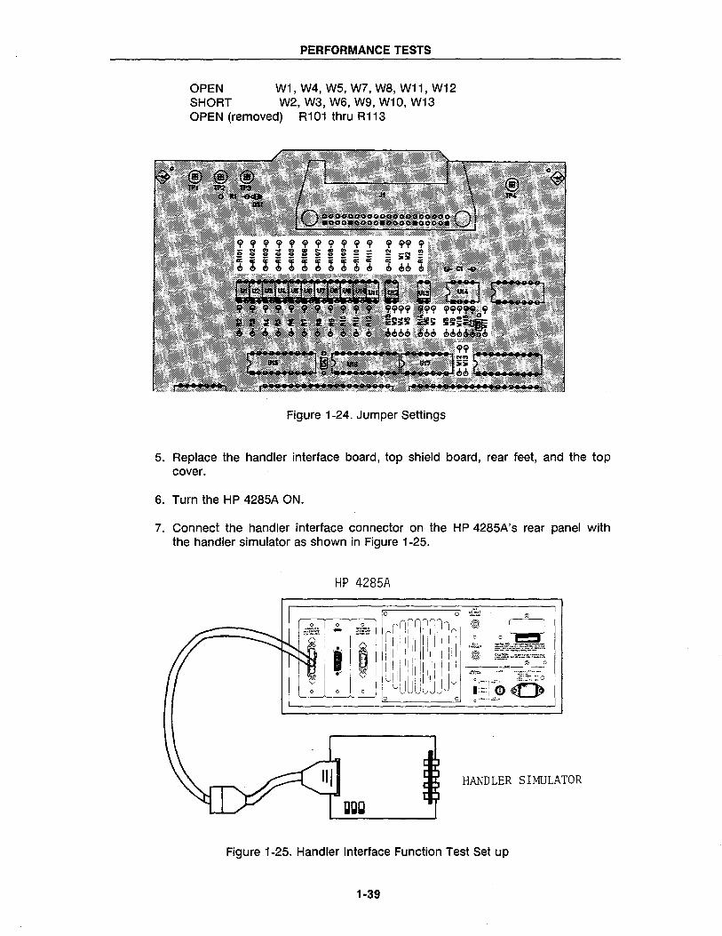
4. Set the jumpers on the handler interface board as shown in Figure 1-24. (Figure 1-24 shows the jumper settings when the board is shipped from the factory.)
1·38
PERFORMANCE TESTS
OPEN W1, W4, W5, W7, W8, W11, W12 SHORT W2, W3, W6, W9, W10, W13 OPEN (removed) R101 thru R113
Figure 1-24. Jumper Settings
5. Replace the handler interface board, top shield board, rear feet, and the top cover.
6. Turn the HP 4285A ON.
7. Connect the handler interface connector on the HP 4285A's rear panel with the handler simulator as shown in Figure 1-25.
HP 4285A
HANDLER SIMULATOR
Figure 1-25. Handler Interface Function Test Set up
1-39
PERFORMANCE TESTS
8. Press the CATALOG/SYSTEM MENU key.
9. Press the 'SELF TEST' soft key to display the SELF TEST page.
10. Move the cursor to the TEST MENU field.
11. Press the 4 and ENTER keys to select the Handler I/F test.
12. Press the 'TEST START' softkey.
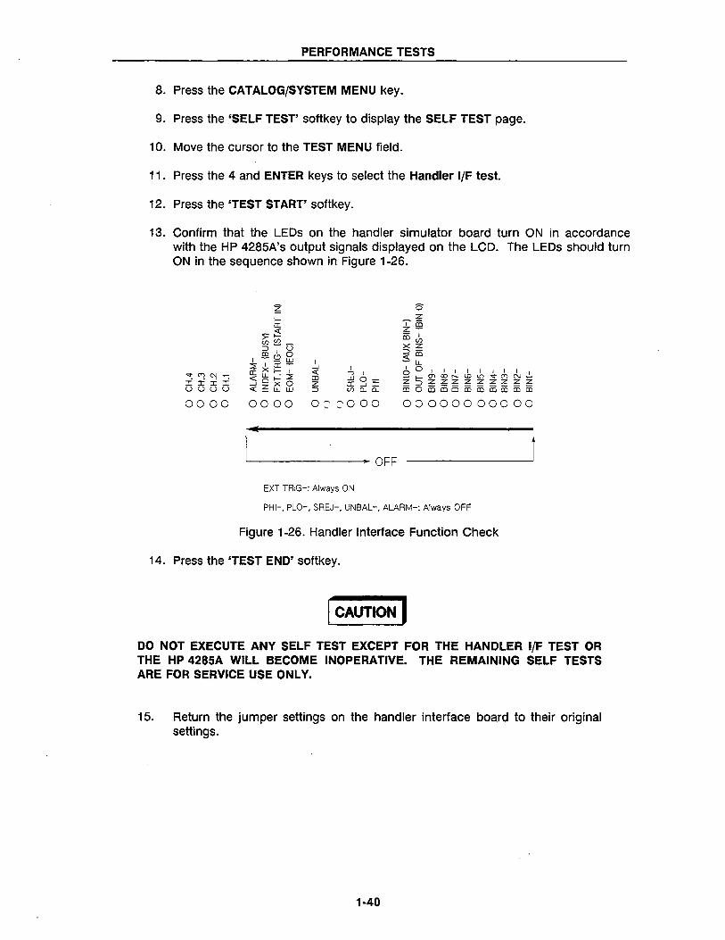
13. Confirm that the LEOs on the handler simulator board turn ON in accordance with the HP 4285A's output signals displayed on the LCD. The LEOs should turn ON in the sequence shown in Figure 1-26.
,",,"(T)C"\l.,....
:i:i:i:i uuuu
I -' « CD z ::>
000000000=,=,000 00000000000
.. ~-------------. OFF
EXT TRIG-: Always ON
PHI-, PLO-, SREJ-, UNBAL-, ALARM-: Always OFF
Figure 1-26. Handler Interface Function Check
14. Press the 'TEST END' softkey.
I CAUTION I DO NOT EXECUTE ANY SELF TEST EXCEPT FOR THE HANDLER I/F TEST OR THE HP 4285A WILL BECOME INOPERATIVE. THE REMAINING SELF TESTS ARE FOR SERVICE USE ONLY.
15. Return the jumper settings on the handler interface board to their original settings.
1·40
PERFORMANCE TESTS
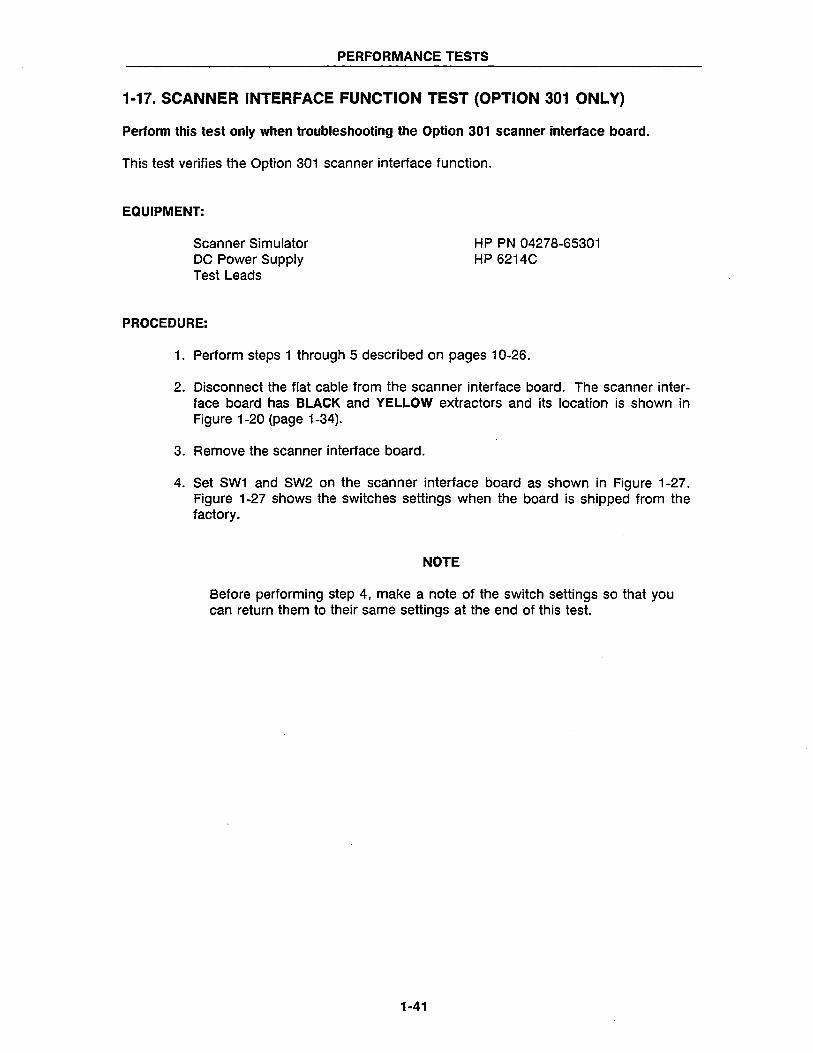
1-17. SCANNER INTERFACE FUNCTION TEST (OPTION 301 ONLY)
Perfonn this test only when troubleshooting the Option 301 scanner interface board.
This test verifies the Option 301 scanner interface function.
EQUIPMENT:
Scanner Simulator DC Power Supply Test Leads
PROCEDURE:
HP PN 04278-65301 HP 6214C
1. Perform steps 1 through 5 described on pages 10-26.
2. Disconnect the flat cable from the scanner interface board. The scanner interface board has BLACK and YELLOW extractors and its location is shown in Figure 1-20 (page 1-34).
3. Remove the scanner interface board.
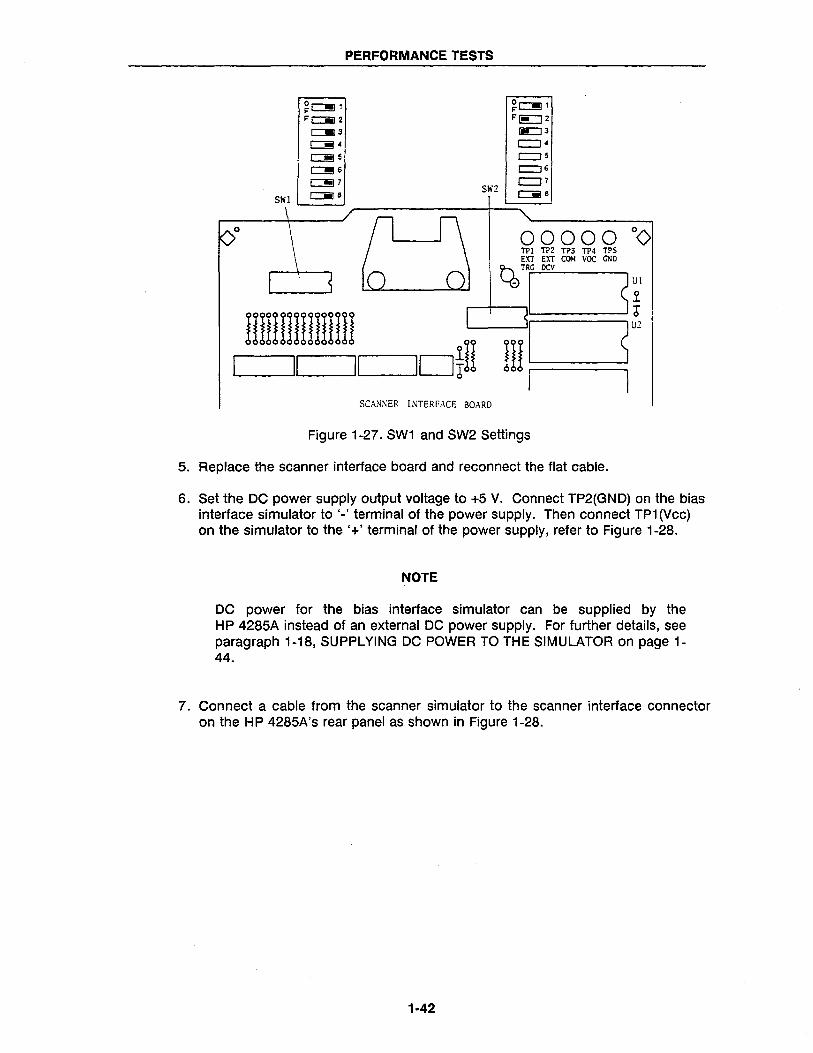
4. Set SW1 and SW2 on the scanner interface board as shown in Figure 1-27. Figure 1-27 shows the switches settings when the board is shipped from the factory.
NOTE
Before performing step 4, make a note of the switch settings so that you can return them to their same settings at the end of this test.
1-41
PERFORMANCE TESTS
~C!!Jl ~~1 -c::iiI2 -~2
c:::J!I 3 (ii::J 3
C!!i ~ c::::J 4
c:::!!J 5 r:::=J 5
c:!!6 r:::=J 6
c:!!J 7 SW2
c::::J 7
SWI c::iiI 8 Cii]8
00000 °0 TPI TP2 TP3 TP4 TPS EXT EXT CO~I VOC GND
~TRG DCV
- I s~ II111!111111!11!
lotH iU I S"' II II o I SCANNER INTERFACE BOARD
Figure 1-27. SW1 and SW2 Settings
5. Replace the scanner interface board and reconnect the flat cable.
6. Set the DC power supply output voltage to +5 V. Connect TP2(GND) on the bias interface simulator to '-' terminal of the power supply. Then connect TP1 (Vcc) on the simulator to the '+' terminal of the power supply, refer to Figure 1-28.
NOTE
DC power for the bias interface simulator can be supplied by the HP 4285A instead of an external DC power supply. For further details, see paragraph 1-18, SUPPLYING DC POWER TO THE SIMULATOR on page 1-44.
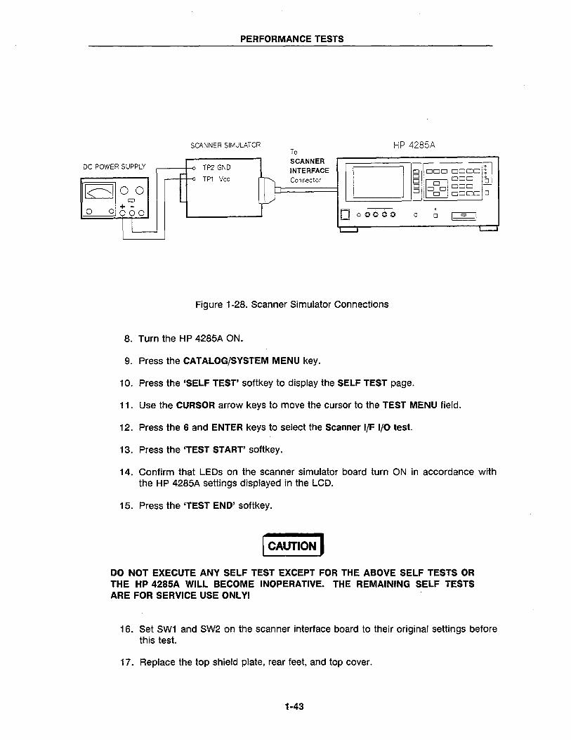
7. Connect a cable from the scanner simulator to the scanner interface connector on the HP 4285A's rear panel as shown in Figure 1-28.
1-42
PERFORMANCE TESTS
SCANNER SIMULATOR HP 4285A To
P SCANNER [ C 11~~DD DD~~
DC POWER SUPPLY TP2 GND INTERFACE TP1 Vee Connector BODO 1:1
8 00 o 10001000 o 0 DODD 0
o 0 ~ 60 0 ~ 0
000010 0 0 I "" I I L- L..-J L..-.-J
Figure 1-28. Scanner Simulator Connections
8. Turn the HP 4285A ON.
9. Press the CATALOG/SYSTEM MENU key.
10. Press the 'SELF TEST' softkey to display the SELF TEST page.
11. Use the CURSOR arrow keys to move the cursor to the TEST MENU field.
12. Press the 6 and ENTER keys to select the Scanner I/F I/O test.
13. Press the 'TEST START' softkey.
14. Confirm that LEOs on the scanner simulator board turn ON in accordance with the HP 4285A settings displayed in the LCD.
15. Press the 'TEST END' softkey.
I CAUTION I DO NOT EXECUTE ANY SELF TEST EXCEPT FOR THE ABOVE SELF TESTS OR THE HP 4285A WILL BECOME INOPERATIVE. THE REMAINING SELF TESTS ARE FOR SERVICE USE ONL YI
16. Set SW1 and SW2 on the scanner interface board to their original settings before this test.
17. Replace the top shield plate, rear feet, and top cover.
1-43
PERFORMANCE TESTS
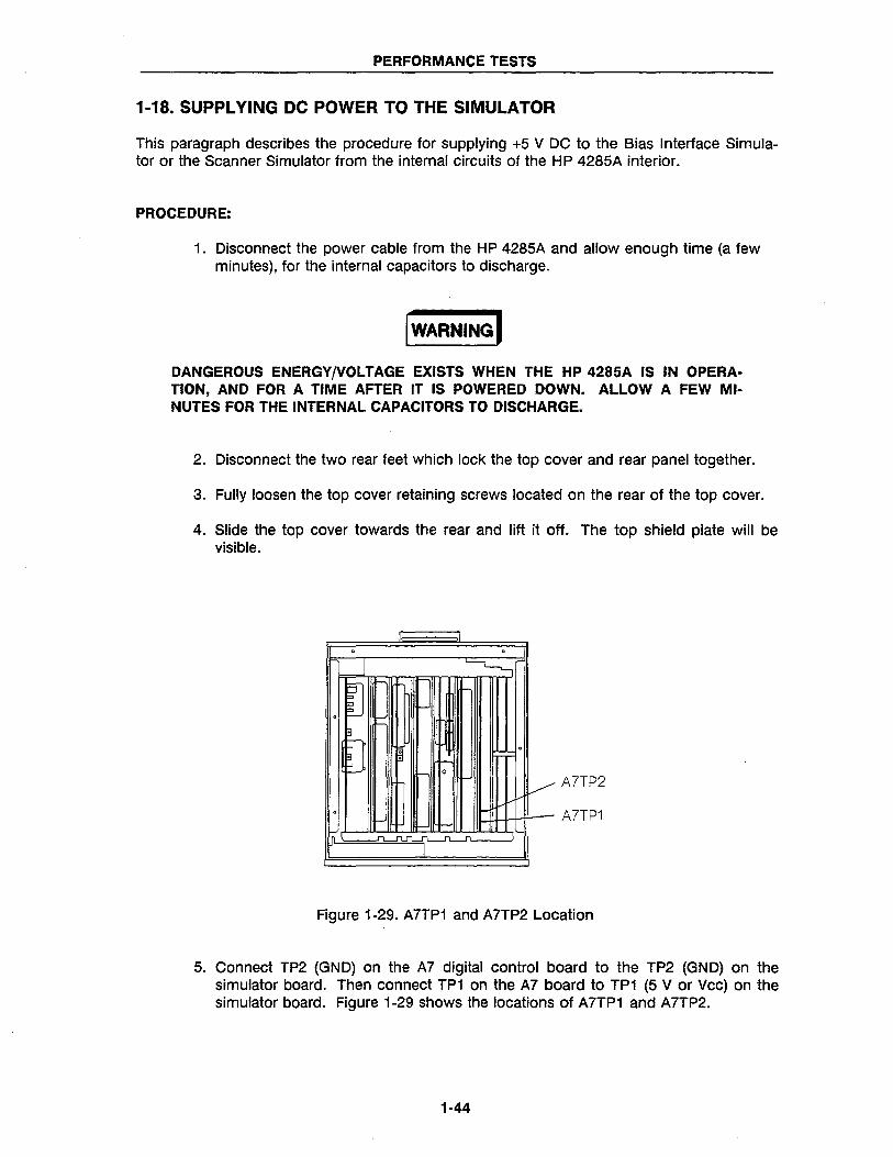
1-18. SUPPLYING DC POWER TO THE SIMULATOR
This paragraph describes the procedure for supplying +5 V DC to the Bias Interface Simulator or the Scanner Simulator from the internal circuits of the HP 4285A interior.
PROCEDURE:
1. Disconnect the power cable from the HP 4285A and allow enough time (a few minutes), for the internal capacitors to discharge.
I WARNING I DANGEROUS ENERGY/VOLTAGE EXISTS WHEN THE HP 4285A IS IN OPERATION, AND FOR A TIME AFTER IT IS POWERED DOWN. ALLOW A FEW MINUTES FOR THE INTERNAL CAPACITORS TO DISCHARGE.
2. Disconnect the two rear feet which lock the top cover and rear panel together.
3. Fully loosen the top cover retaining screws located on the rear of the top cover.
4. Slide the top cover towards the rear and lift it off. The top shield plate will be visible.
. . J ~
iJ "-"I
-J . -l
3
!J . . . -I- 0
~ A7TP2
. I- A7TP1
..n J1.Jl.:[l-I"L-1""l
I
Figure 1-29. A7TP1 and A7TP2 Location
5. Connect TP2 (GND) on the A7 digital control board to the TP2 (GND) on the simulator board. Then connect TP1 on the A7 board to TP1 (5 V or Vcc) on the simulator board. Figure 1-29 shows the locations of A7TP1 and A7TP2.
1·44
CALCULATION SHEET
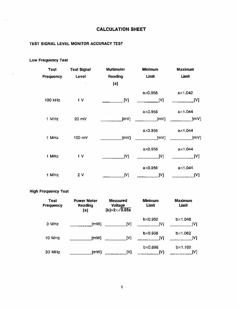
TEST SIGNAL LEVEL MONITOR ACCURACY TEST
Low Frequency Test
Test Test Signal Multimeter Minimum Maximum
Frequency Level Reading Limit Limit
[a]
axO.958 ax1.042
100 kHz 1 V [V] [V] [V]
axO.956 ax1.044
1 MHz 20 mV [mV] [mV] [mV]
axO.956 ax1.044
1 MHz 100 mV [mV] [mV] [mV]
axO.956 ax1.044
1 MHz 1 V [V] [V] [V]
axO.956 ax1.044
1 MHz 2V [V] [V] [V]
High Frequency Test
Test Power Meter Measured Minimum Maximum Frequency Reading Voltage Limit Limit
[a] [b]=2x/O.05a
bxO.952 bx1.048 3 MHz [mW] [V] [V] [V]
bXO.938 bx1.062 10 MHz [mW] [V] [V] [V]
bxO.898 bx1.102 30 MHz [mW] [V] [V] [V]
1
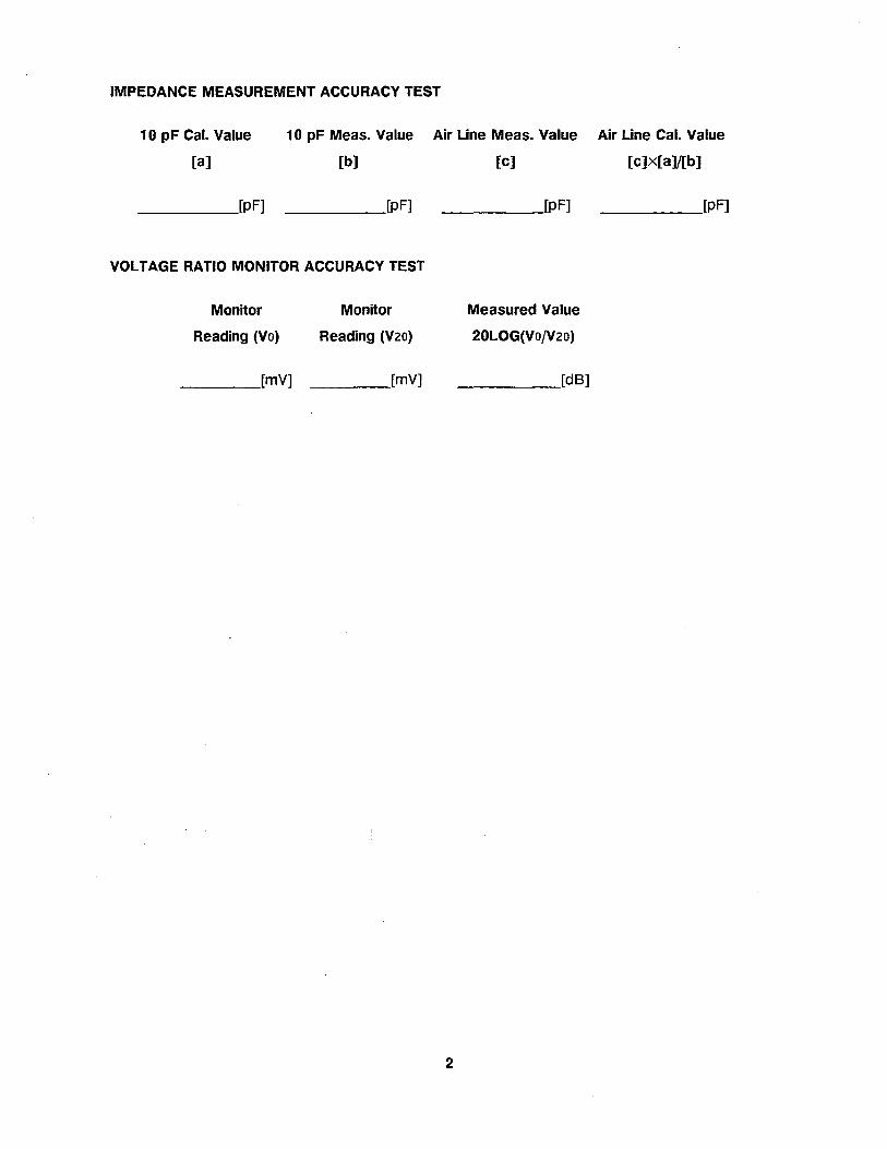
IMPEDANCE MEASUREMENT ACCURACY TEST
10 pF Cal. Value 10 pF Meas. Value Air Line Meas. Value Air Line Cal. Value
[a] [b) [e] [e]x[a]/[b]
____ [pF] [pF] [pF] [pF]
VOLTAGE RATIO MONITOR ACCURACY TEST
Monitor Monitor
Reading (Vo) Reading (V20)
____ [mV] [mY]
2
Measured Value
20LOG{VO/V20)
_____ [dB]
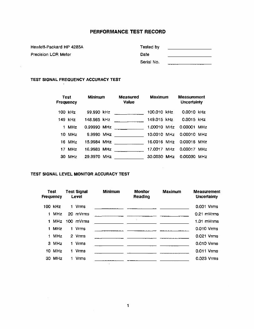
PERFORMANCE TEST RECORD
Hewlett-Packard HP 4285A
Precision LCR Meter
TEST SIGNAL FREQUENCY ACCURACY TEST
Test Minimum Measured Frequency Value
100 kHz 99.990 kHz
149 kHz 148.985 kHz
1 MHz 0.99990 MHz
10 MHz 9.9990 MHz
16 MHz 15.9984 MHz
17 MHz 16.9983 MHz
30 MHz 29.9970 MHz
TEST SIGNAL LEVEL MONITOR ACCURACY TEST
Tested by
Date
Serial No.
Maximum
100.010 kHz
149.015 kHz
1.00010 MHz
10.0010 MHz
16.0016 MHz
17.0017 MHz
30.0030 MHz
Measurement Uncertainty
0.0010 kHz
0.0015 kHz
0.00001 MHz
0.00010 MHz
0.00016 MHz
0.00017 MHz
0.00030 MHz
Test Test Signal Minimum Monitor Maximum Measurement Frequency Level Reading Uncertainty
100 kHz 1 Vrms 0.001 Vrms
1 MHz 20 mVrms 0.21 mVrms
1 MHz 100 mVrms 1.01 mVrms
1 MHz 1 Vrms 0.010 Vrms
1 MHz 2 Vrms 0.021 Vrms
3 MHz 1 Vrms 0.010 Vrms
10 MHz 1 Vrms 0.011 Vrms
30 MHz 1 Vrms 0.023 Vrms
1
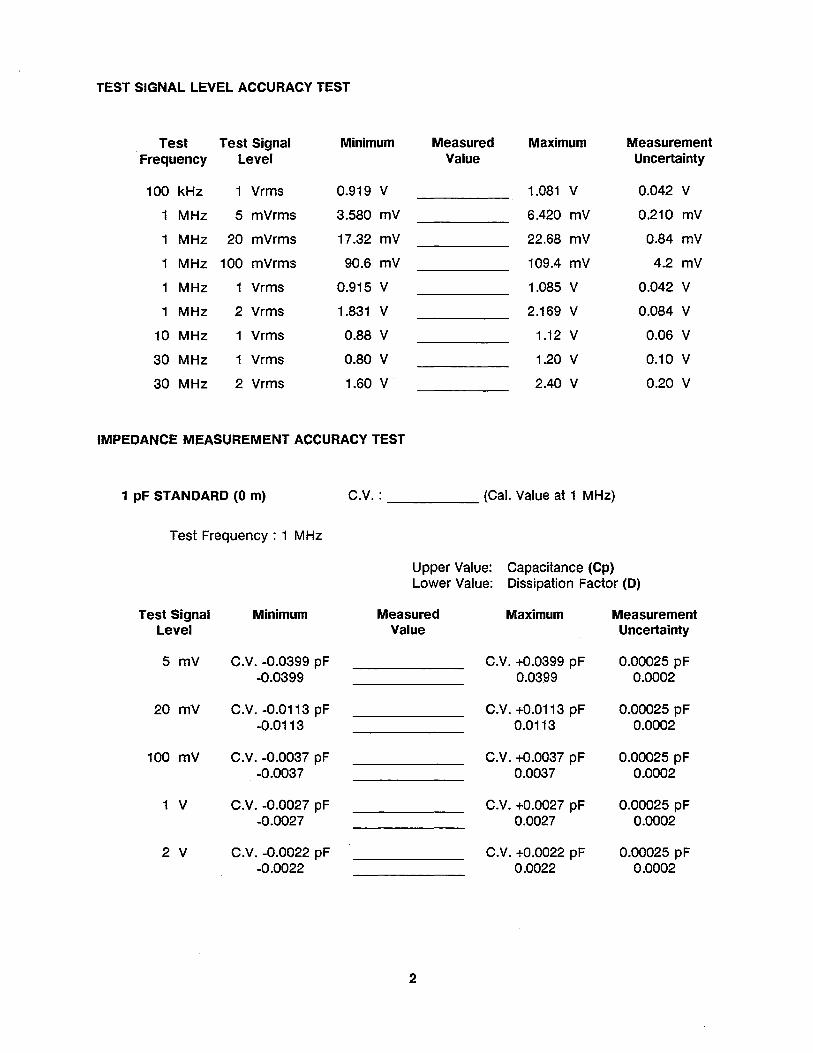
TEST SIGNAL LEVEL ACCURACY TEST
Test Test Signal Minimum Measured Maximum Measurement Frequency Level Value Uncertainty
100 kHz 1 Vrms 0.919 V 1.081 V 0.042 V
1 MHz 5 mVrms 3.580 mV 6.420 mV 0.210 mV
1 MHz 20 mVrms 17.32 mV 22.68 mV 0.84 mV
1 MHz 100 mVrms 90.6 mV 109.4 mV 4.2 mV
1 MHz 1 Vrms 0.915 V 1.085 V 0.042 V
1 MHz 2 Vrms 1.831 V 2.169 V 0.084 V
10 MHz 1 Vrms 0.88 V 1.12 V 0.06 V
30 MHz 1 Vrms 0.80 V 1.20 V 0.10 V
30 MHz 2 Vrms 1.60 V 2.40 V 0.20 V
IMPEDANCE MEASUREMENT ACCURACY TEST
1 pF STANDARD (0 m) c.V. : _____ (Cal. Value at 1 MHz)
Test Frequency: 1 MHz
Upper Value: Capacitance (Cp) Lower Value: Dissipation Factor (D)
Test Signal Minimum Measured Maximum Measurement Level Value Uncertainty
5 mV C.V. -0.0399 pF C.V. +0.0399 pF 0.00025 pF -0.0399 0.0399 0.0002
20 mV C.V. -0.0113 pF C.V. +0.0113 pF 0.00025 pF -0.0113 0.0113 0.0002
100 mV C.V. -0.0037 pF C.V. +0.0037 pF 0.00025 pF -0.0037 0.0037 0.0002
1 V C.V. -0.0027 pF C.V. +0.0027 pF 0.00025 pF -0.0027 0.0027 0.0002
2 V C.V. -0.0022 pF C.V. +0.0022 pF 0.00025 pF -0.0022 0.0022 0.0002
2
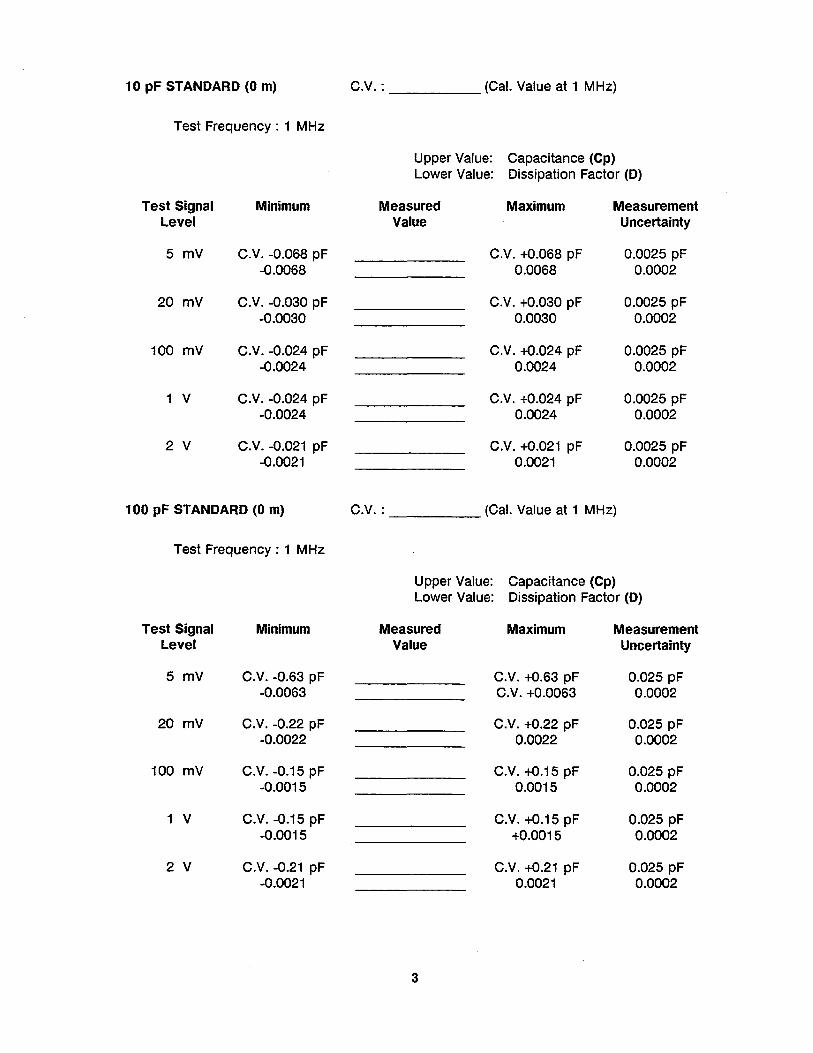
10 pF STANDARD (0 m)
Test Frequency: 1 MHz
Test Signal Minimum Level
5 mV C.V. -0.068 pF -0.0068
20 mV C.V. -0.030 pF -0.0030
100 mV C.V. -0.024 pF -0.0024
1 V C.V. -0.024 pF -0.0024
2 V C.V. -0.021 pF -0.0021
100 pF STANDARD (0 m)
Test Frequency: 1 MHz
Test Signal Minimum Level
5 mV C.V. -0.63 pF -0.0063
20 mV C.V. -0.22 pF -0.0022
100 mV C.V. -0.15 pF -0.0015
1 V C.V. -0.15 pF -0.0015
2 V C.V. -0.21 pF -0.0021
C.V. : _____ (Cal. Value at 1 MHz)
Upper Value: Capacitance (Cp) Lower Value: Dissipation Factor (D)
Measured Maximum Measurement
C.V. :
Value Uncertainty
C.V. +0.068 pF 0.0025 pF 0.0068 0.0002
C.V. +0.030 pF 0.0025 pF 0.0030 0.0002
C.V. +0.024 pF 0.0025 pF 0.0024 0.0002
C.V. +0.024 pF 0.0025 pF 0.0024 0.0002
C.V. +0.021 pF 0.0025 pF 0.0021 0.0002
(Cal. Value at 1 MHz)
Upper Value: Capacitance (Cp) Lower Value: Dissipation Factor (D)
Measured Maximum Measurement Value Uncertainty
C.V. +0.63 pF 0.025 pF C.V. +0.0063 0.0002
C.V. +0.22 pF 0.025 pF 0.0022 0.0002
C.V. +0.15 pF 0.025 pF 0.0015 0.0002
C.V. +0.15 pF 0.025 pF +0.0015 0.0002
C.V. +0.21 pF 0.025 pF 0.0021 0.0002
3
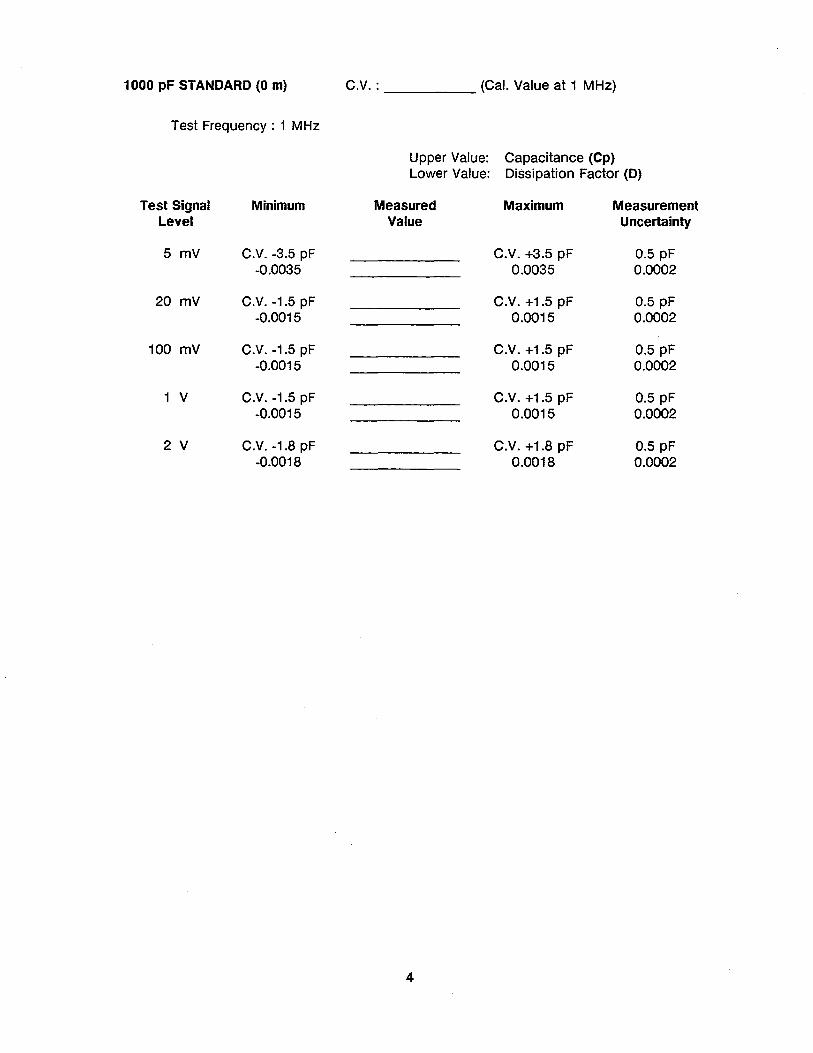
1000 pF STANDARD (0 m) C.V. : _____ (Cal. Value at 1 MHz)
Test Frequency: 1 MHz
Upper Value: Capacitance (Cp) Lower Value: Dissipation Factor (D)
Test Signal Minimum Measured Maximum Measurement Level Value Uncertainty
5 mV C.V. -3.5 pF C.V. +3.5 pF 0.5 pF -0.0035 0.0035 0.0002
20 mV C.V. -1.5 pF C.V. +1.5 pF 0.5 pF -0.0015 0.0015 0.0002
100 mV C.V. -1.5 pF C.V. +1.5 pF 0.5 pF -0.0015 0.0015 0.0002
1 V C.V. -1.5 pF C.V. +1.5 pF 0.5 pF -0.0015 0.0015 0.0002
2 V C.V. -1.8 pF C.V. +1.8 pF 0.5 pF -0.0018 0.0018 0.0002
4
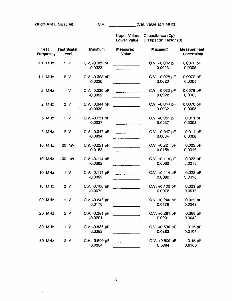
20 cm AIR LINE (0 m) C.V.: (Cal. Value at 1 MHz)
Upper Value: Capacitance (Cp) Lower Value: Dissipation Factor (0)
Test Test Signal Minimum Measured Maximum Measurement Frequency Level Value Uncertainty
1.1 MHz 1 V C.V. -0.032 pF C.V. +0.032 pF 0.0072 pF -0.0023 0.0023 0.0005
1.1 MHz 2 V C.V. -0.028 pF C.V. +0.028 pF 0.0072 pF -0.0020 0.0020 0.0005
2 MHz 1 V C.V. -0.030 pF C.V. +0.030 pF 0.0076 pF -0.0022 0.0022 0.0005
2 MHz 2 V C.V. -0.044 pF C.V. +0.044 pF 0.0076 pF -0.0032 0.0032 0.0005
5 MHz 1 V C.V. -0.051 pF C.V. +0.051 pF 0.011 pF -0.0037 0.0037 0.0008
5 MHz 2 V C.V. -0.047 pF C.V. +0.047 pF 0.011 pF -0.0034 0.0034 0.0008
10 MHz 20 mV C.V. -0.221 pF C.V. +0.221 pF 0.023 pF -0.0158 0.0158 0.0016
10 MHz 100 mV C.V. -0.114 pF C.V. +0.114 pF 0.023 pF -0.0082 0.0082 0.0016
10 MHz 1 V C.V. -0.114 pF C.V. +0.114 pF 0.023 pF -0.0082 0.0082 0.0016
10 MHz 2 V C.V. -0.100 pF C:V. +0.100 pF 0.023 pF -0.0072 0.0072 0.0016
20 MHz 1 V C.V. -0.246 pF C.V. +0.246 pF 0.069 pF -0.0176 0.0176 0.0049
20 MHz 2 V C.V. -0.281 pF C.V. +0.281 pF 0.069 pF -0.0201 0.0201 0.0049
30 MHz 1 V C.V. -0.536 pF C.V. +0.536 pF 0.15 pF -0.0383 0.0383 0.0105
30 MHz 2 V C.V. -0.509 pF C.V. +0.509 pF 0.15 pF -0.0364 0.0364 0.0105
5
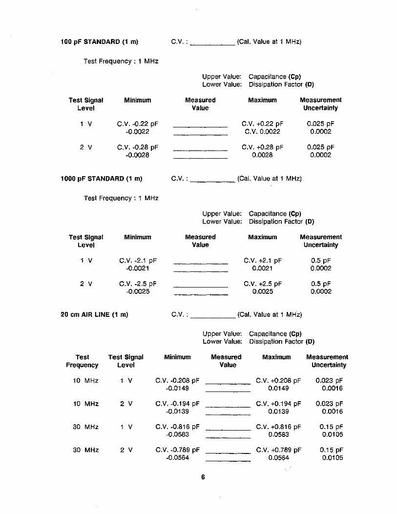
100 pF STANDARD (1 m)
Test Frequency: 1 MHz
Test Signal Minimum Level
1 V C.V. -0.22 pF -0.0022
2 V C.V. -0.28 pF -0.0028
1000 pF STANDARD (1 m)
Test Frequency: 1 MHz
Test Signal Level
1 V
2 V
Minimum
C.V. -2.1 pF -0.0021
C.V. -2.5 pF -0.0025
20 cm AIR LINE (1 m)
Test Test Signal Frequency Level
C.V. : _____ (Cal. Value at 1 MHz)
Upper Value: Capacitance (Cp) Lower Value: Dissipation Factor (D)
Measured Maximum Measurement
C.V. :
Value Uncertainty
C.V. +0.22 pF 0.025 pF C.V.0.0022 0.0002
C.V. +0.28 pF 0.025 pF 0.0028 0.0002
(Cal. Value at 1 MHz)
Upper Value: Capacitance (Cp) Lower Value: Dissipation Factor (D)
Measured Maximum Measurement Value Uncertainty
C.V. +2.1 pF 0.5 pF 0.0021 0.0002
C.V. +2.5 pF 0.5 pF 0.0025 0.0002
C.V. : _____ (Cal. Value at 1 MHz)
Minimum
Upper Value: Capacitance (Cp) Lower Value: Dissipation Factor (D)
Measured Maximum Measurement Value Uncertainty
10 MHz 1 V C.V. -0.208 pF C.V. +0.208 pF 0.023 pF -0.0149 0.0149 0.0016
10 MHz 2 V C.V. -0.194 pF C.V. +0.194 pF 0.023 pF -0.0139 0.0139 0.0016
30 MHz 1 V C.V. -0.816 pF C.V. +0.816 pF 0.15 pF -0.0583 0.0583 0.0105
30 MHz 2 V C.V. -0.789 pF C.V. +0.789 pF 0.15 pF -0.0564 0.0564 0.0105
6
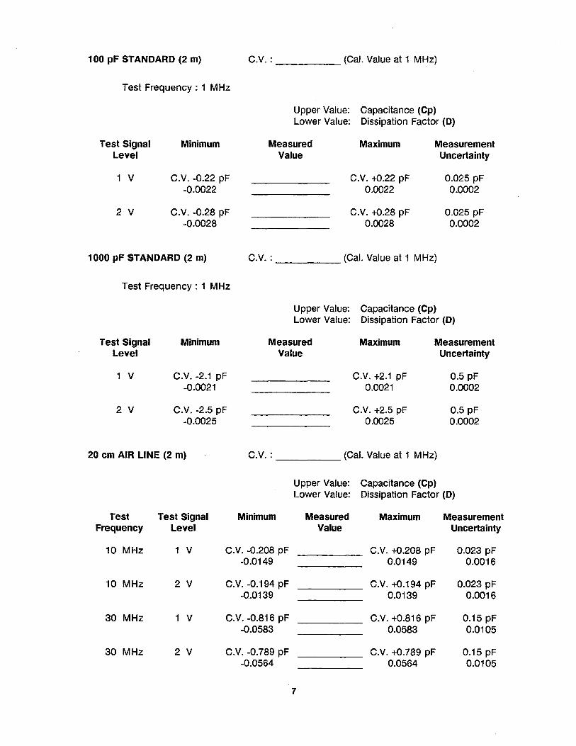
100 pF STANDARD (2 m)
Test Frequency: 1 MHz
Test Signal Level
1 V
2 V
Minimum
C.V. -0.22 pF -0.0022
C.V. -0.28 pF -0.0028
1000 pF STANDARD (2 m)
Test Frequency: 1 MHz
Test Signal Minimum Level
1 V C.V. -2.1 pF -0.0021
2 V C.V. -2.5 pF -0.0025
20 cm AIR LINE (2 m)
Test Test Signal Frequency Level
C.V. : _____ (Cal. Value at 1 MHz)
Upper Value: Capacitance (Cp) Lower Value: Dissipation Factor (0)
Measured Value
Maximum Measurement Uncertainty
C.V. +0.22 pF 0.0022
C.V. +0.28 pF 0.0028
0.025 pF 0.0002
0.025 pF 0.0002
C.V. : _____ (Cal. Value at 1 MHz)
Upper Value: Capacitance (Cp) Lower Value: Dissipation Factor (D)
Measured Maximum Measurement Value Uncertainty
C.V. +2.1 pF 0.5 pF 0.0021 0.0002
C.V. +2.5 pF 0.5 pF 0.0025 0.0002
C.V. : _____ (Cal. Value at 1 MHz)
Minimum
Upper Value: Capacitance (Cp) Lower Value: Dissipation Factor (D)
Measured Maximum Measurement Value Uncertainty
10 MHz 1 V C.V. -0.208 pF C.V. +0.208 pF 0.023 pF -0.0149 0.0149 0.0016
10 MHz 2 V C.V. -0.194 pF C.V. +0.194 pF 0.023 pF -OA0139 0.0139 0.0016
30 MHz 1 V C.V. -0.816 pF C.V. +0.816 pF 0.15 pF -0.0583 0.0583 0.0105
30 MHz 2 V C.V. -0.789 pF C.V. +0.789 pF 0.15 pF -0.0564 0.0564 0.0105
7
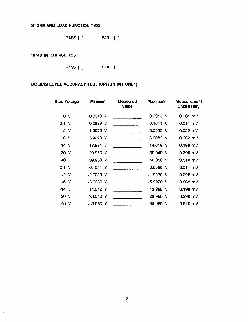
STORE AND LOAD FUNCTION TEST
PASS [ ] FAIL [ ]
Hp·IB INTERFACE TEST
PASS [ ] FAIL [ ]
DC BIAS LEVEL ACCURACY TEST (OPTION 001 ONLY)
Bias Voltage Minimum Measured Maximum Measurement Value Uncertainty
o V -0.0010 V 0.0010 V 0.001 mV
0.1 V 0.0989 V 0.1011 V 0.011 mV
2 V 1.9970 V 2.0030 V 0.022 mV
6 V 5.9920 V 6.0080 V 0.062 mV
14 V 13.981 V 14.019 V 0.198 mV
30 V 29.960 V 30.040 V 0.390 mV
40 V 39.950 V 40.050 V 0.510 mV
-0.1 V -0.1011 V -0.0989 V 0.011 mV
-2 V -2.0030 V -1.9970 V 0.022 mV
-6 V -6.0080 V -5.9920 V 0.062 mV
-14 V -14.012 V -13.988 V 0.198 mV
-30 V -30.040 V -29.960 V 0.390 mV
-40 V -40.050 V -39.950 V 0.510 mV
8
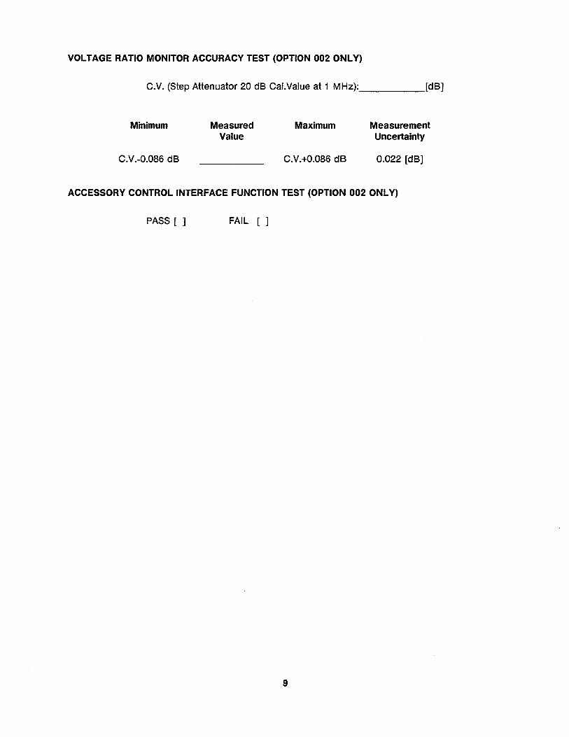
VOLTAGE RATIO MONITOR ACCURACY TEST (OPTION 002 ONLY)
C.V. (Step Attenuator 20 dB Cal.Value at 1 MHz): _____ [dB]
Minimum
C.V.-0.086 dB
Measured Value
Maximum
C.V.+0.086 dB
Measurement Uncertainty
0.022 [dB]
ACCESSORY CONTROL INTERFACE FUNCTION TEST (OPTION 002 ONLY)
PASS [ ] FAIL [ ]
9

APPENDIXA
MANUAL CHANGES
A-1.INTRODUCTION
This appendix contains the information required to adapt this manual to earlier versions or configurations of the HP 4285A than the current printing date of this manual. The information in this manual applies directly to HP 4285A Precision LCR Meters whose serial number prefix is listed on the title page of this manual.
A-2. MANUAL CHANGES
To adapt this manual to your HP 4285A, refer to Tables A and S, and make all of the manual changes listed opposite your instrument's serial number and ROM-based firmware's version.
Instruments manufactured after the printing of this manual may be different than those documented in this manual. Later instrument versions will be documented in a manual changes supplement that will accompany the manual shipped with that instrument. If your instrument serial number is not listed on the title page of this manual or in Table A, it may be documented in a yellow MANUAL CHANGES supplement.
Refer to the description of the *IDN? command in CHAPTER 9, COMMAND REFERENCE, OPERATION MANUAL for confirmation of the ROM-based firmware's version.
Table A. Manual Changes by Serial Number
Serial Prefix or Number
Make Manual Changes
There are no earlier configurations than the printing date of this manual.
Table S. Manual Changes by Firmware's Version
Version Make Manual Changes
There are no earlier versions than the printing date of this manual.
A·1

NOTES
A-2

REGIONAL SALES AND SUPPORT OFFICES
For more information about Agilent Technologies test and measurement products, applications, services, andfor a current sales office listing, visit our web site: http://www.agilent.com/find/tmdir. You can also contact one of the following centers and ask for a test and measurement sales representative. 11129199
United States: Agilent Technologies Test and Measurement Call Center P.O.Box 4026 Englewood, CO 80155-4026 (tel) 1 8004524844
Canada: Agilent Technologies Canada Inc. 5150 Spectrum Way Mississauga, Ontario L4W 5Gl (tel) 1 877 8944414
Europe: Agilent Technologies Test & Measurement European Marketing Organization P.O.Box 999 1180 AZ Amstelveen The Netherlands (tel) (31 20) 547 9999
Japan: Agilent Technologies Japan Ltd. Call Center 9-1, Takakura-Cho, Hachioji-Shi, Tokyo 192-8510, Japan (tel) (81) 426567832 (fax) (81) 426 56 7840
Latin America: Agilent Technologies Latin American Region Headquarters 5200 Blue Lagoon Drive, Suite #950 Miami, Florida 33126 U.S.A. (tel) (305) 267 4245 (fax) (305) 267 4286
AustralialNew Zealand: Agilent Technologies Australia Pty Ltd
347 Burwood Highway Forest Hill, Victoria 3131 (tel) 1-800629485 (Australia) (fax) (61 3) 9272 0749 (tel) 0 800 738 378 (New Zealand) (fax) (64 4) 802 6881
Asia Pacific: Agilent Technologies 241F, Cityplaza One, 1111 King's Road, Taikoo Shing, Hong Kong (tel) (852)-3197-7777 (fax) (852)-2506-9284