Embed Size (px)
Citation preview
Agilent 8645 Signal GeneratorCommunicationProduct Note 8645-2
A catalog of 8645A information
Table of contents
Operation related topics. . . . . . . . . . . . . . . . . . . . . . . . . . . . . . . . . . . . . . . . . . . . . . . . . . . . . . . . . . . . . 3Block diagram and theory of operation . . . . . . . . . . . . . . . . . . . . . . . . . . . . . . . . . . . . . . . . . . . . . . . . . . 3 Timebase configurations . . . . . . . . . . . . . . . . . . . . . . . . . . . . . . . . . . . . . . . . . . . . . . . . . . . . . . . . . . . . . . 5Internal audio source. . . . . . . . . . . . . . . . . . . . . . . . . . . . . . . . . . . . . . . . . . . . . . . . . . . . . . . . . . . . . . . . . 6Frequency sweep capabilities . . . . . . . . . . . . . . . . . . . . . . . . . . . . . . . . . . . . . . . . . . . . . . . . . . . . . . . . . . 7Externally doubled outputs to 2060 MHz . . . . . . . . . . . . . . . . . . . . . . . . . . . . . . . . . . . . . . . . . . . . . . . . . 8Operation as a phase noise reference . . . . . . . . . . . . . . . . . . . . . . . . . . . . . . . . . . . . . . . . . . . . . . . . . . . . 9Programming with HP-SL . . . . . . . . . . . . . . . . . . . . . . . . . . . . . . . . . . . . . . . . . . . . . . . . . . . . . . . . . . . . 10Command sequence independence using HP-SL . . . . . . . . . . . . . . . . . . . . . . . . . . . . . . . . . . . . . . . . . . 11
Performance related topics . . . . . . . . . . . . . . . . . . . . . . . . . . . . . . . . . . . . . . . . . . . . . . . . . . . . . . . . . . 12Phase noise performance. . . . . . . . . . . . . . . . . . . . . . . . . . . . . . . . . . . . . . . . . . . . . . . . . . . . . . . . . . . . . 12Spurious performance . . . . . . . . . . . . . . . . . . . . . . . . . . . . . . . . . . . . . . . . . . . . . . . . . . . . . . . . . . . . . . . 14Third order intermodulation . . . . . . . . . . . . . . . . . . . . . . . . . . . . . . . . . . . . . . . . . . . . . . . . . . . . . . . . . . 15Divided outputs below 515 MHz . . . . . . . . . . . . . . . . . . . . . . . . . . . . . . . . . . . . . . . . . . . . . . . . . . . . . . . 16Stereo separation quality. . . . . . . . . . . . . . . . . . . . . . . . . . . . . . . . . . . . . . . . . . . . . . . . . . . . . . . . . . . . . 17Minimizing fan noise . . . . . . . . . . . . . . . . . . . . . . . . . . . . . . . . . . . . . . . . . . . . . . . . . . . . . . . . . . . . . . . . 18
Frequency agility . . . . . . . . . . . . . . . . . . . . . . . . . . . . . . . . . . . . . . . . . . . . . . . . . . . . . . . . . . . . . . . . . . 19Functional description of frequency agile operation . . . . . . . . . . . . . . . . . . . . . . . . . . . . . . . . . . . . . . . 19Faster frequency switching using multiple agile generators . . . . . . . . . . . . . . . . . . . . . . . . . . . . . . . . . 20Frequency accuracy of agile outputs. . . . . . . . . . . . . . . . . . . . . . . . . . . . . . . . . . . . . . . . . . . . . . . . . . . . 22Relating phase error and frequency accuracy . . . . . . . . . . . . . . . . . . . . . . . . . . . . . . . . . . . . . . . . . . . . 23Amplitude dynamic range while frequency hopping . . . . . . . . . . . . . . . . . . . . . . . . . . . . . . . . . . . . . . . 24Amplitude shaping of agile outputs. . . . . . . . . . . . . . . . . . . . . . . . . . . . . . . . . . . . . . . . . . . . . . . . . . . . . 25
Modulation . . . . . . . . . . . . . . . . . . . . . . . . . . . . . . . . . . . . . . . . . . . . . . . . . . . . . . . . . . . . . . . . . . . . . . 26High rate, high deviation FM . . . . . . . . . . . . . . . . . . . . . . . . . . . . . . . . . . . . . . . . . . . . . . . . . . . . . . . . . 26Simultaneous modulations . . . . . . . . . . . . . . . . . . . . . . . . . . . . . . . . . . . . . . . . . . . . . . . . . . . . . . . . . . . 27Digitized FM operation . . . . . . . . . . . . . . . . . . . . . . . . . . . . . . . . . . . . . . . . . . . . . . . . . . . . . . . . . . . . . . 28AC coupled FM . . . . . . . . . . . . . . . . . . . . . . . . . . . . . . . . . . . . . . . . . . . . . . . . . . . . . . . . . . . . . . . . . . . . . 29
Special capabilities . . . . . . . . . . . . . . . . . . . . . . . . . . . . . . . . . . . . . . . . . . . . . . . . . . . . . . . . . . . . . . . . 30Tailored operation through special functions. . . . . . . . . . . . . . . . . . . . . . . . . . . . . . . . . . . . . . . . . . . . . 30Protecting classified instrument settings . . . . . . . . . . . . . . . . . . . . . . . . . . . . . . . . . . . . . . . . . . . . . . . . 31Storage registers and sequential recall . . . . . . . . . . . . . . . . . . . . . . . . . . . . . . . . . . . . . . . . . . . . . . . . . 32Offsets and multipliers of frequency and amplitude . . . . . . . . . . . . . . . . . . . . . . . . . . . . . . . . . . . . . . . 33Built-in calibration functions . . . . . . . . . . . . . . . . . . . . . . . . . . . . . . . . . . . . . . . . . . . . . . . . . . . . . . . . . 34Finding failures with internal diagnostics . . . . . . . . . . . . . . . . . . . . . . . . . . . . . . . . . . . . . . . . . . . . . . . 35
2
This product note is actually acompilation of many brief prod-uct notes, each concerned with aparticular aspect of the 8645Aagile signal generator. Includedin these pages are explanationsof how this unique signal genera-tor operates, the capabilities it
has to offer and the performanceit can provide. The objective ofthis product note is to be a refer-ence guide for the owner of a8645A, to help maximize the use-fulness and performance of thisagile signal generator in theintended application. While none
of the topics are covered in greatdetail and other literature mayoffer a more thorough treatmentof a subject, these summariesshould provide sufficient infor-mation to help in many situa-tions.
Operation related topics
Block diagram and theoryof operation
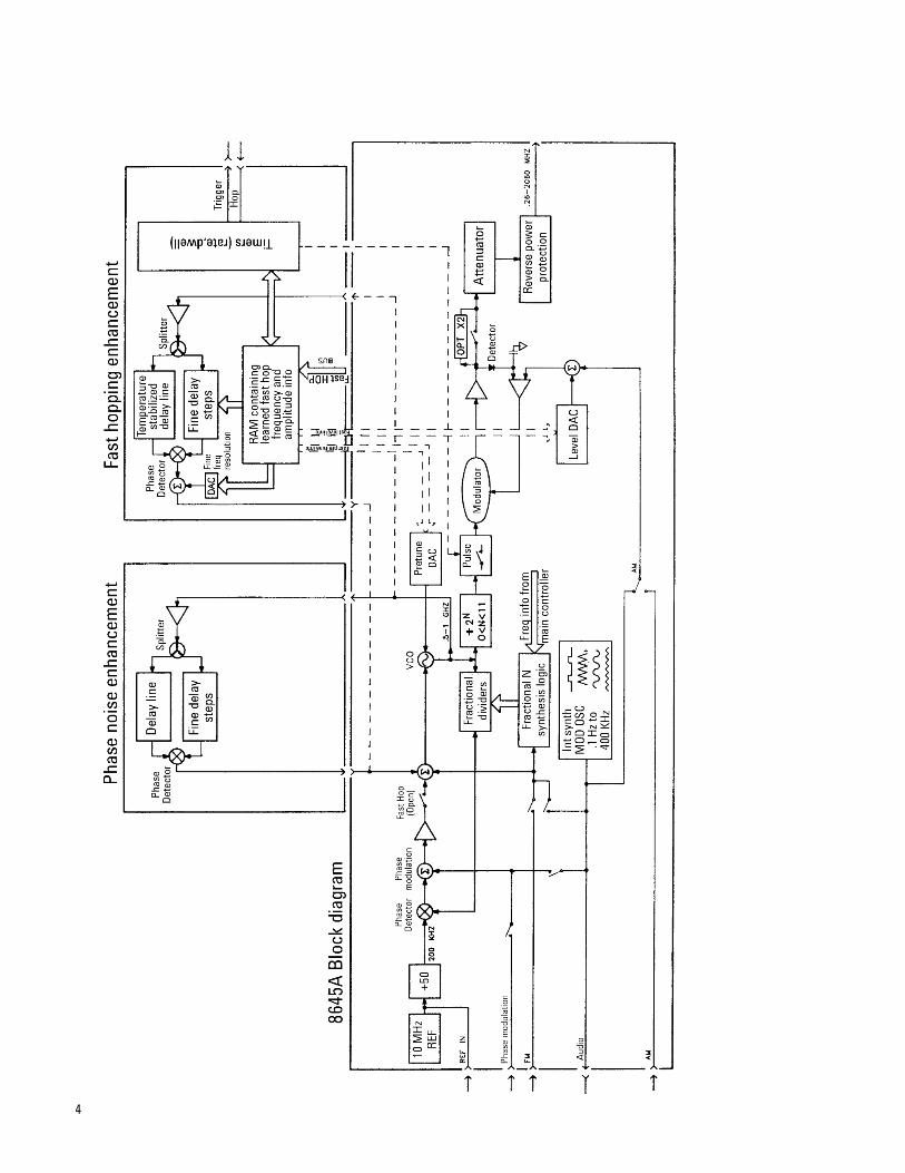
The basis of the 8645A is a sin-gle fractional N loop controllinga VCO operating in the frequen-cy range of 515 to 1030 MHz.The reference signal for thisphase lock loop originates fromeither an internal 10 MHz oscil-lator or an external input. Anextensive divider section at theoutput of the phase lock loopprovides coverage down to 252 kHz and a doubler in theoutput section extends the fre-quency range to 2060 MHz. Allfour modulation types are imple-mented in the 8645A with eitherthe internal 400 kHz synthesizerintegrated circuit providing themodulation waveform or anexternal input. Frequency modu-lation uses two techniquesincluding an analog signalsummed into the VCO tuninginput and a digitized FM tech-nique that directly modifies thefractional N number of the phaselock loop. Phase modulation sig-nals are summed directly intothe fractional N phase lock loop.Pulse modulation occurs directlyafter the divider section.Amplitude modulation is accom-
plished in the output sectionthrough control of the AutomaticLevel Control (ALC). The AM sig-nal is summed together with thelevel DAC which sets the ampli-tude level that reaches the atten-uators. The combination of thelevel DAC, the AM signal, andthe attenuators (up to 120 dB ofattenuation) determine the actu-al output level of the 8645A. TheReverse Power Protection (RPP)prevents the output circuits fromdamaging signals externallyinput through the generator’soutput. Controlling all of thishardware in the many states theuser can set up is a Motorola68000 microprocessor.
The basic block diagram summa-rized above produces all the tra-ditional functions of a signalgenerator. For the applicationsintended for the 8645A, thephase noise and spurious signalsmust be very low at offsetsgreater than approximately 10 kHz. A major advantage ofthe block diagram is that aclean-up loop based on a delayline and a phase detector can beadded in parallel to the fraction-al N phase lock loop. The 70 nsecdelay line in the clean-up loop ofthe phase noise enhancementsection decreases the phasenoise and spurious signals tolevels required by communica-tions hardware tests.
Besides high performance out-puts for traditional applications,the 8645A is designed to providesequences of many frequenciesin rapid order. Frequencyswitching is specified as fast as15 usec between frequencies. Toaccomplish this switching speed,the fractional N phase lock loopis opened and replaced by adelay line frequency lock loop.Phase noise and spurious signalson the VCO output are againdecreased by the delay line andphase detector in the fast hopenhancement section. VCO set-tings learned before fast hopoperation begins are sent to theVCO through a pretune DAC inthe order of the output frequen-cies the user wants and at therate programmed. Amplitudeinformation is simultaneouslysent to the level DAC. A hard-ware state machine programmedby the microprocessor providesall the fast control signals need-ed while fast hop operation isunderway.
Many of the operational areasbriefly discussed on this pageare covered more thoroughly inother parts of this product note.Refer to the table of contents fora listing of the topics.
3
4
Timebase configurations
The frequency stability of the8645A depends a great deal onthe reference oscillator in use.The standard internal timebaseis a non-ovenized 10 MHz crystaloscillator with a typical agingrate of ±2 ppm per year. Withthis timebase, a 1 GHz output ofthe signal generator would notvary more than ±2 kHz in a yeardue to timebase aging. However,the frequency drift due to tem-perature changes may be twicethis amount because this oscilla-tor is not ovenized. Although the8645A has several design fea-tures to minimize internal tem-perature fluctuations, thestandard timebase could drift byas much as ±4 ppm over a tem-perature range variation of 0 to+55 degrees centigrade.
Option 001 of the 8645A adds amore stable 10 MHz ovenizedtimebase to the instrument. Theaging rate is specified to be bet-ter +0.0005 ppm or a 0.5 Hz vari-ation of a 1 GHz output in 24hours after a 10 day warm-up.Frequency drift due to a ambienttemperature change of 0 to +55degrees centigrade is typicallyless than +0.006 ppm. The fre-quency of this timebase can bemechanically adjusted through ahole in the rear panel using atweaker. Voltage control of thetimebase frequency is availableusing the Electronic FrequencyControl (EFC) input. The maxi-mum ±10 volt EFC input signalwill produce a ±1 Hz frequencychange of the 10 MHz output.
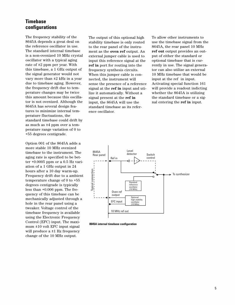
The output of this optional highstability timebase is only routedto the rear panel of the instru-ment as the oven ref output. Anexternal jumper cable is used toinput this reference signal at theref in port for routing into thefrequency synthesis circuits.When this jumper cable is con-nected, the instrument willsense the presence of a referencesignal at the ref in input and uti-lize it automatically. Without asignal present at the ref ininput, the 8645A will use thestandard timebase as its refer-ence oscillator.
To allow other instruments touse the timebase signal from the8645A, the rear panel 10 MHzref out output provides an out-put of either the standard oroptional timebase that is cur-rently in use. The signal genera-tor can also utilize an external10 MHz timebase that would beinput at the ref in input.Activating special function 161will provide a readout indictingwhether the 8645A is utilizingthe standard timebase or a sig-nal entering the ref in input.
5
8645ARear panel
Typi
cal c
onne
ctio
n
Standard referenceoscillator(10 MHz)
Optionalhigh stabilityoscillator(10 MHz)
Switchcontrol
To synthesizer
Ref in
Leveldetector
Oven refoutput
EFC input
10 MHz ref out
8645A internal timebase configuration
Internal audio source
The internal audio source in the8645A can generate four basicwaveforms of sine, sawtooth,square, and white Gaussiannoise. Waveforms are generatedby a numerical synthesis tech-nique. The heart of the synthe-sizer is a Digital WaveformSynthesis Integrated Circuit(DWSIC). The DWSIC generates acontinuous stream of numbersthat represents instantaneouslevels of the waveform. This “dig-ital” waveform is then convertedto an analog signal by adigital-to-analog converter. Theanalog signal is conditioned byconventional analog circuitryand routed to various parts ofthe signal generator. The condi-tioning circuits include a sampleand hold to remove DAC switch-ing noise, filters to remove quan-tization noise, and amplifiers toboost the output.
The internal audio source isused in the signal generator formodulation, sweeping, calibra-tion, and diagnostics. To theuser, the source appears like aninternal function generator usedto modulate the carrier with thefour basic waveforms. It is alsoused as a ramp voltage into theFM circuitry during phase con-tinuous sweep that disallowsinternal modulation being activethis sweep mode. This source isused as an accurate DC refer-ence to calibrate FM deviationand AM depth when these modu-lations are active. The built-indiagnostics use the source forDC and AC signals to test vari-ous modules in the instrument.And of course the audio signal isavailable at the front panel audiooutput with programmable wave-forms, amplitude, and frequency.
The type of waveform producedcan be selected by activatingspecial function 130 or via GPIBwith the commandLFS:Waveform <type> where<type> is sin, square, saw, orWGN (for white Gaussian noise).The frequency can be selectedover a range of 0.1 Hz to 400kHz. Sawtooth and squarewaverates should be limited to lessthan 50 kHz because the outputcircuitry degrades the perform-ance at higher rates. Frequencyaccuracy is equal to the internaltimebase accuracy of the instru-ment. Frequency switchingspeed of the source is typicallyless than 30 msec. Output levelis programmable and rangesfrom 1 mV to 1 Vrms into a 600ohm load with a specified accu-racy of ±20 mV. Adjusting theoutput level will effect theamount of internal modulationpresent such that a decrease inoutput level will proportionatelydecrease the amount of internalmodulation. This feature can beused to increase the amount ofexternal modulation allowedduring simultaneous internaland external modulation. Thesum of the internal and externalvoltages should not exceed 1.4 Vpeak during simultaneousmodulation or clipping distor-tion may occur.
6
Frequency sweep capabilities
The 8645A was designed to havethree different types of frequen-cy sweep operation to accommo-date a wide variety of applications.As is evident from the descrip-tions that follow, the wide devia-tion FM capabilities and the fasthop operation offer uniquesweep capabilities not present inthe typical RF signal generator.
The most useful sweep for find-ing the frequency response ofnarrowband devices is the phasecontinuous frequency sweep.The instrument uses the widedeviation FM circuitry to createa phase-continuous output overspans as wide as twice the maxi-mum FM deviation available forthat carrier frequency range. Inthe main VCO band of 515 to1030 MHz the maximum span is20 MHz. This range is decreasedby half for each divider bandbelow this main carrier band. Asweeptime range of 10 msec to10 seconds is allowed for anyspan that is chosen. Only a lin-ear frequency sweep is allowed.Another capability that offersvery high accuracy of each fre-quency point of the sweep is thedigitally stepped frequencysweep. The instrument will stepthe synthesizer across any spanset by the user in a linear or log
frequency spacing. The numberof discrete points output willdepend on the span and sweep-time that is set. Sweeptime canrange from 0.5 to 1000 secondswith each discrete point requir-ing typically 90 msec to com-plete. To reduce the amount ofswitching transients spurs dueto each frequency change, theoutput level is reduced approxi-mately 60 dB between each dis-crete frequency. This amplitudeblanking may cause dropouts onthe displayed frequencyresponse. Due to these dropoutsit may be more useful to specifya fast hop sweep for wide fre-quency spans as the followingdescribes.
A unique frequency sweep capa-bility of the 8645A is the fasthop sweep. Utilizing the frequen-cy agile capability, large frequen-cy spans with 1000 discretefrequency steps in as little as100 msec per sweep. The num-ber of frequency steps variesaccording to the sweeptime andfrequency range selected witheach discrete step taking 30microseconds for outputs from128 to 2060 MHz. The user canset a sweeptime range from 10 msec to 100 seconds.
Although the output is blankedbetween each frequency step asin digitally stepped sweep, theduration of the blanking is soshort that the detector used tomeasure the frequency responsewill typically not show thedropout on the oscilloscope ornetwork analyzer. Either a linearand log distribution of frequencysteps can be selected.
Each of the three types of fre-quency sweep described abovecan be operated in a continuousrepetitive output or a singlesweep output triggered by thepress of a key or an HP-SL com-mand. Additionally the digitallystepped and fast hop sweeptypes can be operated manuallyusing the front panel knob orup/down arrow keys. Up to threemarkers can be entered for out-put during a sweep. When thesweep reaches the marker fre-quency a 0 volt signal is outputfrom the Z axis port on the rearpanel. The Z axis output is +1 volt during a sweep and +5 volts during retrace to blankthe CRT of an oscilloscope. TheX axis output of 0 to 10 voltsmatched to the progress of thefrequency sweep.
7
Externally doubled outputs to 2060 MHz
For applications requiring out-puts above the 1030 MHz maxi-mum frequency of the standard8645A, consideration can begiven to either ordering the8645A with the optional internaldoubler, installing the 11867Aretrofit kit or using an externaldoubler. This technical briefsummarizes the capabilities andperformance the user can expectwhile using one such externaldoubler, the 11721A frequencydoubler, to increase the frequencyrange of the 8645A to 2060 MHz. The 11721A frequency doubler isa passive, full-wave rectifyingdoubling circuit that wasdesigned to minimize conversionloss over a wide frequencyrange. Its output frequencyrange is 10 MHz to 2560 MHz. Atinput levels above +13 dBm the
doubler has an almost constantconversion loss of approximately11 dB. This typical conversionloss after the +16 to +18 dBmmaximum output of the 8645Aresults in an output signal levelof +5 to +7 dBm for the average11721A external doubler. Theharmonic and spurious contentof the output is almost complete-ly a function of the input signal.Note that harmonics input todoubler (specified at <–30 dBcfor the 8645A below 1030 MHz)will increase approximately 6 dBdue to the doubling function.The same 6 dB increase will bepresent on the phase noise ofthe carrier. Any frequency mod-ulation at the input to the dou-bler will double in deviationalso.
For frequency agile signals, the11721A has no measurable affecton the frequency switching timeup to the fastest time of 15 usecavailable on the 8645A.
By using special function 111frequency multiplier with anentered multiplier of 2, the dis-play of the 8645A will representthe signal at the output of thedoubler as a convenience.Simultaneously, the doubler’sconversion loss can be enteredas an amplitude offset to cali-brate the display for the actualamplitude at the doubler’s out-put.
More general information aboutthe 11721A frequency doubler inuse with the 8662A synthesizedsignal generator is available inapplication note 283-2 (litera-ture number 5952-8217).
8
Operation as a phasenoise measurement reference
Among several techniques formeasuring the phase noise of asource is the method of using asecond source to demodulate thephase instability using a phasedetector. Commonly referred toas the phase detector method,this process requires that thesecond source or referencesource have as good or betterphase noise performance thanthe source being tested. It is alsorequired that one of the sourceshave an FM capability in orderto maintain phase quadrature atthe output of the phase detector.These needs for good phasenoise performance and FM capa-bility often result in a genericsignal generator being used asthe reference source of a phasenoise measurement system. Thesubject of this brief product noteis how to optimize use of the8645A as a reference source forphase noise measurements. Moreinformation on the measurementtechnique itself can be found inliterature related to productssuch as the 11729C carrier noisetest set or 3048A phase noisemeasurement system.
Several features of the 8645Amake it a good choice for use asa phase noise measurementsource. These include the widecarrier frequency range, an out-put power of +16 dBm and alarge FM deviation range. Thephase noise of the 8645A’s out-put is very low at offsets greaterthan 10 kHz from the carrier, asis commonly required for testingchannelized communicationdevices or systems. The 8645Ahas very few spurs on its outputwhich simplifies the detectionand interpretation of spurs fromthe test source. The typicalphase noise and spurious per-formance is indicated in thegraph included in the “phasenoise performance” summary ofthis product note.
As with any reference sourceused in the phase detectormethod, only as much FM devia-tion as required to establish thephase lock loop for the measure-ment should be used. Minimizingthe FM deviation decreases thenoise contribution of the FM cir-cuits and reduces the potentialfor an unstable Phase Lock Loop(PLL). The design of the 8645Auses two different FM implemen-tations that the user shouldchoose between according to theFM deviation range required.The standard FM is recommend-ed for phase noise measure-ments that use a PLL bandwidthof less than 1.6 kHz. Variationsin the group delay of the FM cir-cuits for deviation settings tosupport more than 1.6 kHz couldcause inaccurate measurements
or loop oscillations. For situa-tions that require more loopbandwidth, it is recommendedthat the fast hop mode be acti-vated for the measurement. Inthe fast hop mode the groupdelay of the FM is very low andremains constant at higher FMdeviations. Although the phasenoise at low offsets increases inthis mode, it is generally accept-able as sources that requiremore FM range to maintainquadrature also have higherphase noise to be measured.
One other unique characteristicof the 8645A is that several cir-cuits internally are reset when-ever the center frequency settingis changed so the output is notphase continuous during thesechanges. The output is decreasedby more than 60 dB during theseresets so that the unspecifiedoutput during the transition willnot affect the user’s device. Thistransition period lasts less than85 msec typically. While thisoperational characteristic willnot affect a phase noise meas-urement in progress, it will beapparent when the center fre-quency of the 8645A is beingtuned as the beatnote disappearsmomentarily with each change.This signal interruption willcause the PLL to momentarilybreak lock. Activating specialfunction 105 amplitude mutingdisables this amplitude blankingbut the unspecified transitionsof the output signal could stillresult in perturbations whiletuning frequency.
9
Programming with HP-SL
Hewlett-Packard SystemsLanguage (HP-SL) is the pro-gramming language for instru-mentation adopted by AgilentTechnologies. This language usesstandard GPIB hardware andwill be used in many new Agilentproducts. The 8645A is the firstsignal generator to implementHP-SL. HP-SL uses self-explana-tory commands and is flexiblefor beginning and advanced pro-grammers. Programs written inHP-SL for the 8645A will be com-patible with the other generatorswith the exception of commandsassociated with unique functionsof the signal generator such asfast hop capabilities. This isintended to minimize softwaremodifications by the customerwhen hardware is upgraded orreplaced.
Many Agilent divisions have con-tributed to the development ofHP-SL and will use it as part ofan interface system that con-forms to the new IEEE 488.2standard. The advantage of thenew IEEE standard is that itdefines common global com-mands such as for the instru-ment preset function, as well ashardware and protocol that iscompatible with previous stan-dards. In the short term HP-SLwill be easier to learn and selfdocumenting and in the longterm, HP-SL will provide a morecommon language to reduce thecost of software support.A simple example shows how
HP-SL commands are selfexplanatory and what a typicalprogram for the 8645A couldlook like. The following programlines will perform an instrumentpreset on the signal generator,set the RF frequency to 500 MHzand the amplitude to 10 dBm,and turn the RF output on.
100 Output 719; “*RST”
200 Output 719; “Frequency:CW 500 MHz”
300 Output 719; “Amplitude:Level 10 dBm”
400 Output 719; “Amplitude:State on”
This example programming canbe further simplified becausewith HP-SL commands can becombined in a single outputstatement without regard for theorder in which the instrumentwill execute the commands. Thismeans that HP-SL instrumentswill take in the full command“message” of a single line of pro-gramming before executing anyof the contents. The commandmessage defines the final instru-ment state that is wanted with-out regard for the order ofcommands given. This eliminatesthe problem of programming anunallowed instrument state suchas increasing FM deviationbefore increasing carrier fre-quency. However care must betaken that each individual mes-sage only defines one finalinstrument state and not several.With this HP-SL capability, theprevious example can bechanged to the following:
Since “*RST” defines a completeinstrument state on its own, itcannot be combined with theother commands or it will beuncertain which state will result.This example also shows the useof the short form of commandsas well as implied commandsand implied units. The semicolonis used to separate commands ina single output, and the colon isused to separate words in a sin-gle command. The commandswith asterisks are used with allIEEE 488.2 compatible instru-ments that can execute thatfunction. In HP-SL commands,spaces should be between wordsand arguments but not before orafter punctuation. Much moreinformation on HP-SL program-ming with the 8645A is providedin the HP-SL ProgrammingGuide (literature number5951-6710).
10
100 Output 719; “*RST”
200 Output 719; “Freq 500 MHz;Ampl:Lev 10; Stat on”
Command sequence independence using HP-SL
A current problem with instru-ment programming is that eachcommand that is received by aninstrument is executed immedi-ately. When the user is trying toset up a complete instrumentstate, the order in which thecommands are sent must be cor-rect so that each intermediatestate is valid. ImplementingHP-SL on the 8645A has elimi-nated this command orderdependence through the creationof command “messages”. A mes-sage contains all of the instru-ment commands that will resultin the desired instrument state.None of the commands areimplemented by the instrumentuntil the complete message isreceived. In this structure, theorder of the commands in themessage is irrelevant. The pro-grammer constructs messages todescribe the final instrumentstate that is needed without wor-rying about the way the instru-ment gets to that state.
For example, suppose a signalgenerator had the followingcapability dependencies betweencarrier and FM deviation range:
Carrier range FM deviation range
100 MHz to 1 GHz 1 MHz to 10 MHz
10 MHz to 100 MHz 100 Hz to 1 MHz
With the previous control struc-ture, it is impossible to seriallychange the frequency and FMdeviation because either com-mand to go to another range willcause an error as the otherparameter is out of range. Theprogrammer would have to cre-ate an intermediate state such asturn FM off before changing thefrequency so that all intermedi-ate states were valid. ThePerformance Signal Generator(PSG) implementation of theIEEE 488.2 standard eliminatesthis problem because only thefinal state need be valid. Themessage of “Freq 200 MHz; FM 8 MHz” would put the instru-ment right to the new state thatis wanted.
It is important that the userdoes not define an ambiguousstate within a message by modi-fying the same function morethan once in a single message. Itis uncertain (and undefined)what the final instrument statewould be if the 8645A receivedthe following messages:
Freq:step 10 HZ;:Freq up;:Freq:step 100HZ;:Freq down
As the frequency is repetitivelychanged in a single message thefinal frequency of the instru-ment will depend on the execu-tion order of the commands,which is not defined.
*RST;Freq 123 MHz;FM:State on
In this case the *RST commandcould be executed after the othercommands, canceling theireffects. The command *RSTdefines a complete instrumentstate by itself and so should besent alone.
FM:State on;:AM:State on;:Mod:Stateoff;:Freq 100 MHz;:Mod:State on
In this case the user has speci-fied conflicting states for themod:state command.
If the execution order of a groupof commands is important, theuser must send a separate mes-sage for each command.
11
Performance relatedtopics
Phase noise performance
The 8645A agile signal generatorwas designed to minimize thephase noise of its signal at off-sets corresponding to typicalchannel spacings of communica-tion systems. These offsets ofinterest are generally greaterthan 10 kHz from the carrier.Simultaneously, the close-innoise was reduced to assure lowresidual FM for receiver testing.The following summarizes thephase noise performance of the8645A.
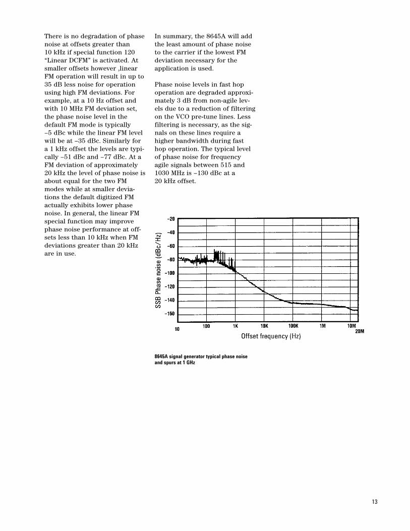
For offsets less than 100 Hz, theprimary contributor of phasenoise is the fractional N synthe-sis circuitry in a single phaselock loop if FM is not active. Atypical level is –80 dBc (in a 1 Hz noise bandwidth) at 100 Hzoffset for carriers in the mainband of 515 to 1030 MHz. Thephase noise at offsets between100 Hz and 10 MHz is deter-mined primarily by a frequencydiscriminator inside a frequencylocked loop. The typical phasenoise level at a 20 kHz offset is–133 dBc in the main band.Beyond 10 MHz the phase noiseis that of the VCO or output sec-tion divider noise floor atapproximately –150 dBc. Thesephase noise levels at offsets lessthan 10 MHz will decrease byapproximately 6 dB each timethe carrier frequency is reducedby half due to the dividers in theblock diagram. This phase noisereduction continues until thedividers’ noise floor of approxi-mately –150 dBc/Hz is reached.
At offset frequencies of 20 kHzor greater phase noise does notincrease when FM is active aslong as the deviation used is lessthan approximately 5% of themaximum FM deviation allowedat that carrier frequency. Forexample, in the main band of515 to 1030 MHz the maximumavailable deviation is 10 MHz,but the phase noise performanceat a 20 kHz offset remains thesame as in CW operation if 500 kHz or less of FM deviationis set by the user. If the full 10MHz deviation is used, the phasenoise at this 20 kHz offset typi-cally increases by 17 dB to –116 dBc.
As with any signal generator,close-in phase noise of the8645A goes up as the FM devia-tion increases. This is becausethe internal FM circuits con-tribute more noise as the devia-tion (gain) increases. Forexample, the phase noise level isapproximately –80 dBc at a 10 Hzoffset for a main band outputfrom 515 to 1030 MHz with FMdeviation set to 100 Hz. If FMdeviation is set to 100 kHz thephase noise at this offsetincreases by 35 dB to typically–45 dBc. Using the full 10 MHzdeviation, the maximum avail-able in this main band, phasenoise will go up another 40 dBto approximately –5 dBc at a 10 Hz offset.
12
There is no degradation of phasenoise at offsets greater than 10 kHz if special function 120“Linear DCFM” is activated. Atsmaller offsets however ,linearFM operation will result in up to35 dB less noise for operationusing high FM deviations. Forexample, at a 10 Hz offset andwith 10 MHz FM deviation set,the phase noise level in thedefault FM mode is typically –5 dBc while the linear FM levelwill be at –35 dBc. Similarly fora 1 kHz offset the levels are typi-cally –51 dBc and –77 dBc. At aFM deviation of approximately20 kHz the level of phase noise isabout equal for the two FMmodes while at smaller devia-tions the default digitized FMactually exhibits lower phasenoise. In general, the linear FMspecial function may improvephase noise performance at off-sets less than 10 kHz when FMdeviations greater than 20 kHzare in use.
In summary, the 8645A will addthe least amount of phase noiseto the carrier if the lowest FMdeviation necessary for theapplication is used.
Phase noise levels in fast hopoperation are degraded approxi-mately 3 dB from non-agile lev-els due to a reduction of filteringon the VCO pre-tune lines. Lessfiltering is necessary, as the sig-nals on these lines require ahigher bandwidth during fasthop operation. The typical levelof phase noise for frequencyagile signals between 515 and1030 MHz is –130 dBc at a 20 kHz offset.
8645A signal generator typical phase noiseand spurs at 1 GHz
13
Spurious performance
The spurious performance of the8645A is quite good, but thereare still spurs to be found. Thisproduct note describes thesources of potential spurs andwhere in the spectrum they canbe found.
The harmonically related spursare caused by nonlinear opera-tion of amplifiers in the RF path.The specification for harmonicsof the carrier for carrier fre-quencies below 1030 MHz is –30 dBc. Typically, they are bet-ter than –35 dBc. Subharmonicstypically are caused by a dividerin the Phase Lock Loop (PLL)signal path that affects the mainVCO output and amplification inthe output section. The domi-nant subharmonic is at 0.5 * theVCO frequency. This spur in themain band (515 to 1030 MHz) isless than –70 dBc, in the dou-bled band (1030 to 2060 MHz) itis less than –45 dBc, and below515 MHz it is practically nonexistent.
Nonharmonically related spursare caused by a number ofthings. These include the powersupply, microphonics, and digitalcircuits. The power supply spursare all input line frequency relat-ed and are typically less than–60 dBc in the main band. Acareful design of the regulatorsand power distribution circuitskeeps the power supply ripple inthe instrument very low. Thefront panel display circuitry canproduce a spur at an offset ofapproximately 1.5 kHz. Its levelis less than 20 dB above the sig-nal generator’s phase noisemeasured in a 1 Hz noise band-width. Microphonics is anothersource of spurs that depends onhow severe the signal generatoris being vibrated. One inherentsource is the fan, with the loca-tion of the spur dependent onfan speed which in turn is afunction of the instrument’s tem-perature. The fan spur is usuallyless than 20 dB above the noise.
A spur can be produced in theoutput when external modula-tion (i.e., FM) is enabled and theinternal audio source is active.Its location will be at the audiosource frequency. The level willdepend on the amount of FMdeviation programmed. Forexample, if 1 MHz deviationusing an external FM source isset and the internal audio oscil-lator is at 100 kHz, it will causea spur at approximately –80 dBc.It is recommended that theaudio oscillator be turned offwhen not in use.
One final type of spur to be men-tioned is due to the fractional-Ncircuitry in the PLL. When theoutput frequency in the mainband is not an integer multipleof 400 kHz, a spur will be pro-duced. This spur is caused bythe PLL divider alternatingbetween two divider numbers(integers) such that the averagefrequency is the desired frequen-cy. Compensation in the PLL cir-cuitry keeps these spurs to lessthan 25 dB above the phasenoise of the output signal (in a 1 Hz noise bandwidth). The frac-tional-N spur frequency in themain band will be at half the dif-ference between the closest inte-ger multiple of 400 kHz and theinstrument’s output frequency.
14
Third order intermodulation
Third Order Intermodulation(TOI) products result when theoutputs of two signal generatorsare summed together in a com-bining network. These spurioussignals occur at frequencies2*F1-F2 and 2*F2-F1, where F1and F2 are the output frequen-cies of signal generators 1 and 2respectively. The unwantedintermodulation signals are theresult of the Automatic LevelControl (ALC) loops in the out-put sections of each generator“seeing” the other generator’ssignal and responding to it as ifit were unwanted modulation onthe desired output signal. If thefrequency difference betweenthe desired output signal and theother generator’s signal is lessthan the bandwidth of the ALCloop, the loop can respond to thesignal’s presence. In trying toremove this single sided “modu-lation”, the loop inadvertentlyproduces modulation sidebandsof its own. This unfortunateprocess is also occurring in theother generator’s ALC loop atthe same time. The overall resultis third order intermodulationproducts accompanying the twotest signals at the output of thecombiner.
Since signal generator outputsare usually combined to providea stimulus to test the TOI per-formance of receiver front ends,it is important that the TOIproducts caused by the signalgenerators be well below thoseexpected from the device undertest. One way to reduce the TOIproducts from the signal genera-tors is to use a directional cou-pler rather than a resistivesummer to combine the two sig-nal generator outputs. Anotherway to decrease TOI products isto reduce the bandwidths of thesignal generator ALC loops wellbelow the frequency spacingused. This approach can betaken to the extreme of entirelyopening (or disabling) the ALCloops, since an open loop can bethought of as an infinitely nar-row (0 Hz) bandwidth becausethe ALC will not respond to asignal at any frequency.
The 8645A has five differentALC loop bandwidths: 200 kHz,50 kHz, 5 kHz, 60 Hz, and 0 Hz.The instrument automaticallyselects the optimum bandwidthfor lowest AM distortion, fastestamplitude switching speed, andlowest TOI. The three widestbandwidths are used only whenAM is enabled. In that case, thebandwidth selected is a functionof carrier frequency. The 60 Hzbandwidth is used whenever AMis turned off. At this bandwidth,the TOI level produced by twosignal generators with a frequen-cy difference of 25 kHz and withoutput levels of +8 dBm is typi-cally less than –55 dB. For betterperformance with smaller fre-quency differences, the 0 Hzbandwidth can be selected usingspecial function 104.
15
Divided outputs below 515 MHz
To create signals below the mainVCO frequency range of 515 to1030 MHz, the 8645A divides theVCO into lower frequencyoctaves using digital dividersswitched into the signal path. Atotal of 11 divide bands extendthe frequency coverage down to252 kHz. This technique is verygood for spectral purity as witheach division of the signal thephase noise and spurs aredecreased approximately 6 dB.This reduction in phase noisecontinues until the noise floor ofthe dividers is reached which istypically approximately –150dBc. Residual FM is also reducedas the carrier frequency is divid-ed down. However, there areother consequences that must bedealt with as the followingdescribes.
When FM is applied to the VCOthe amount of deviation that ispresent in a divided output isdivided by the same number asthe carrier. For the lowest or11th divider band this divisionequals 211 or a divisor of 2048.This large divisor is one of thereasons the 8645A has a maxi-mum of 10 MHz of FM deviationin the main band. With this largedeviation available in main bandthere is still 10 MHz / 2048 or4.8 kHz of deviation available inthe 252 to 503 kHz band. FMrate also decreases with eachsuccessive divide band becauseeach band has 2 half-octave lowpass filters present to reduce thelevel of harmonics at the output.
Phase continuous frequencysweep is also reduced by theaction of the divider circuits.The actual frequency change inthis function is an FM operationusing the full FM deviation avail-able in the main band to get a20 MHz span (±10 MHz). Theavailable span width is reducedby half with each successivedivide in the same way FM deviation is.
The AM bandwidth is alwayslimited to something much lessthan the carrier frequencybecause the level detector(which is designed to follow theAM envelope or any level varia-tion and not the RF) would startdetecting the RF waveform if thebandwidth were too wide. In adivided output, the AM isapplied to the divided RF output(not the main VCO signal) andtherefore the AM bandwidthmust be less than the band’slowest RF signal so as not toreact to the carrier. But as AMbandwidth is reduced, amplitudeswitching time gets longer andAM distortion is worse. In the8645A three AM bandwidths areused to optimize the AM per-formance and still allow fastamplitude transitions as is nec-essary for fast hop operation.Over the frequency range of 128to 2060 MHz a 100 kHz band-width is used, a 50 kHz band-width is active for signals downto 8 MHz and a 5 kHz bandwidthlimits signals for outputs to 252 kHz. In fast hop operation,the amplitude is decreased byapproximately 30 dB by the AMcircuitry during each frequencychange of the main VCO. Thereduction of AM bandwidth forthe lower divide bands whichcauses slower amplitude switch-ing time is the only reason thefast hop switching time is longerfor low carrier frequencies.
16
Stereo separation quality
Stereo separation is a measureof a receiver’s ability to separatethe left and right channel of astereo signal. To a listener, thisis a measure of the receiver’sability to recreate the spatialimpression of a stereo signal. Inan FM system the audio informa-tion is received as a left + rightsignal and a left-right signal. Thereceiver decodes the left channelby adding the two signals anddecodes the right channel bysubtracting the two signals. Theseparation of the channelsdepends on the cancellation ofthe right channel during theaddition and cancellation of theleft channel during subtraction.For this to happen properly, therelative phase and amplitude ofthe two original signals must bekept equal.
In a signal generator the FM lin-earity and group delay flatnessdetermines whether the relativephase and amplitude of thestereo signal is preserved.Typically, test signals near 1 kHzand 38 kHz are used to modulatethe signal generator to teststereo separation in a receiver.The quality of the test signal,and therefore the measurement,will depend on the FM linearityand group delay at these fre-quencies.
Radio manufacturers specifystereo separation in dB as theamplitude difference between adesired signal in one channeland an undesired signal in theother channel. The desired signalis a known test signal used tostimulate one channel. The unde-sired signal is the unwanted“leakage” or coupling of the testsignal into the other channel.Radio manufacturers typicallyspecify 40 dB separation whichis beyond most listener’s abilityto detect distortion or “crosstalk”between the channels.
The 8645A in the fast hop opera-tion uses linear FM and has lowgroup delay. Typical stereo sepa-ration is greater than 55 dB inthis mode and is sufficient totest most consumer radio equip-ment. Using digitized FM in stan-dard operation of the 8645A willresult in poor stereo separationdue to variations in the groupdelay of the FM signal path.Activating special function 120linear FM with AC coupling setprovides separation similar tothe fast hop mode but has thedisadvantage that signals below20 Hz cannot be used. Linear FMwith DC coupling also has goodstereo separation but poor cen-ter frequency resolution.Therefore, for the best stereoseparation with the 8645A theuser should activate the fast hopmode with DC coupling.
17
Minimizing fan noise
Increasing concern over the levelof audio noise coming from testinstruments has resulted in sev-eral design features to minimizenoise from the PerformanceSignal Generator (PSG). Theobjectionable noise from testinstruments comes from the fansused to create the internal air-flow to cool the electronics andprevent heat related failures.These modifications from whatwas done in the past are relatedto careful fan selection, fanspeed and rear panel fan cover.An overriding consideration wasto maintain the high reliabilitydesign goal for the PSG by ensur-ing sufficient airflow for coolingcomponents.
A number of fans were evaluatedfor use in PSG. Along with beingof the right physical size andpushing enough air, the noiselevel when running was consid-ered. Of the fans that wouldmeet the cooling requirements,the one with lowest noise levelwas chosen. The next step wasto evaluate the noise contribu-tion the fan cover was responsi-ble for. The shape of the grillwork of the cover changes thenoise level due to the fan bladespassing close to it in their rota-tion. An analysis of noisesources of various grill shapeswith the blade shape of the lownoise fan led to making severalgrills to try out. The combinationof the grill and low noise fanthat produced the lowest noisewas chosen for implementationin PSG.
The final step taken to reducethe noise of the PSG producedthe biggest benefit for the aver-age user. Minimum airflowrequired for high reliability oper-ation is calculated assuming theambient temperature at the max-imum operating temperaturespecified. For PSG, this tempera-ture is 55 degrees centigrade(131 degrees fahrenheit). Fanrotation speed is set to provideenough airflow at this high envi-ronmental temperature. At lowertemperatures, less airflow isneeded to keep internal compo-nents at their specified operat-ing temperature so the fan speedcould be reduced. In most previ-ous instruments the fan speed isheld constant at the highest air-flow needed for high ambienttemperatures. In PSG instru-ments, the fan speed is con-trolled by a temperature sensorto vary airflow as needed tomaintain as much as possibleconstant internal temperatureover the full environmentalrange of 0 to 55 degrees centi-grade. Since the average userhas the instrument in environ-ments much less than 55 degreescentigrade, the fan speed ismuch slower than the maximumit could do. As fan noise isdirectly related to the fan speed,in typical use the PSG instru-ments are much quieter thanprevious signal generators. Thisprovides a much more pleasantenvironment for the operator ofa performance signal generator.
18
Frequency agility
Functional description offrequency agile operation
The frequency agile operation ofthe 8645A is unique in both itscapabilities and its operation.The following describes what theinstrument is actually doingwhile in fast hop operation.
Entering the fast hop modeEither pressing the fast hopmode select key or sending thecounterpart HP-SL commandwill put the instrument in thefast hop synthesis mode. Theinstrument’s output frequency isno longer phase locked. Insteadthe frequency accuracy dependson an extremely stable VCO anda frequency locked loop. At thispoint the fast hop subsystem isset to idle allowing parameterssuch as output level and FMdeviation to be programmed thesame as in non-agile operation.
Entering channel information,hop rate, and dwell timeAs the user enters each frequen-cy and amplitude into a channellocation, the information is putinto non-volatile memory for useduring the learn operation thatprecedes frequency hopping. If achannel sequence is entered forthe channel numbers, this infor-mation is also put in this memo-ry. A hop rate and dwell timeare always in memory and aremodified according to any newvalues entered. Any conflictbetween the hop rate and dwelltime is not checked until the fre-quency learn operation is initiat-ed.
Initiating the learn operationThe learn operation recalls eachfrequency and amplitude storedin each channel location andsets the phase locked synthesizerand the ALC of the output toeach value. At each setting theinstrument records the VCO tun-ing voltage and the ALC amplifi-er gain. The output is turned offwhile this process is underway.The hop rate and dwell are alsoverified that they will not con-flict for the frequencies (andassociated switching time) in thechannel table. The only channelsthat are part of these operationsare those in the currentsequence table. If the user didnot specify a sequence table, the8645A creates one that reflectsthe number and order of theentries in the channel table. Theinstrument does not programfrequencies and amplitudes ofany channels that are repeatedin the sequence table, rather theVCO and ALC settings alreadylearned are copied into memory.The learn operation always lastsa minimum of 10 seconds toensure that the hopping circuitsare exercised sufficiently to sta-bilize any thermal changes in thetransition from the idle state. Asmore unique frequencies areincluded in the channel table ittakes longer to set up each stateto record the settings and so thelearn time required increases.For 2400 channels, learn time isapproximately 1 minute. Thistime doubles to 2 minutes if FMis active.
Initiating hop operationWhen the 8645A begins frequen-cy hopping a unique “fast con-troller” takes control of the VCOand ALC. The data contained inthe fast hop memory is present-ed to the hardware to duplicateeach channel in the order itappears in the sequence table.Depending on which fast hopmode is active, the fast con-troller may cycle through thesequence table at a programmedrate or enable external inputs totrigger a hop to the next channelor to select which sequence loca-tion to output based on the inputat the fast hop bus. The instru-ment will remain in the hopstate until the idle or learn oper-ation is selected or a function ischanged that would invalidatethe data in the fast hop memory(such as changing the FM devia-tion). Rate and dwell can bechanged without having to learnagain.
19
Faster frequency switching using multipleagile generators
The 8645A can provide frequen-cy agile outputs with hop ratesof up to 50,000 hops/seconddepending on the carrier fre-quencies above 128 MHz, 11,000 hops/second above 8MHz, and 2,000 hops/secondabove 252 kHz. While these hoprates are fast enough for themajority of agile applications,sometimes higher hop rates maybe needed. The 8645A has beendesigned to make it easy to syn-chronize and combine the out-puts of multiple units in order tocreate agile signals at higher hoprates. This product note explainshow to configure multiple unitsto work together.
Frequency agile operations thatinclude interfacing with a radiousually involve control of the fol-lowing parameters: frequencyselection, data valid, hop trigger-ing, dwell time, modulation andamplitude. Of these parametersonly data valid and hop trigger-ing require extra attention whensynchronizing the outputs of twoor more 8645A’s. In a typicalinstrument set-up, each 8645Awill have loaded into memoryidentical channel and sequencetables of all the frequencies andamplitudes to be output. Dwelltime for each hop frequency willbe constant and controlled bythe instrument’s internal timers.The modulation waveform to beplaced on the carrier would beinput to both external FM inputswith the same FM deviation seton each generator. The frequen-cy control word to select eachchannel to be output accordingto its location in the sequencetable would also be input to thefast hop bus of both instrumentssimultaneously. The RF outputof each generator would bebrought together with a combin-er for input to the device undertest. All of these control inputsand instrument settings areidentical to that required foroperating a single 8645A.
By alternating which signal gen-erator receives the data validand hop trigger signals it is pos-sible to give one 8645A time toswitch frequencies while a sec-ond unit is producing the neededoutput. Then while the secondunit is changing frequencies thefirst can provide the next out-put. In this way the combinedagile output can be switched atmuch higher rates than are pos-sible with a single 8645A. Eachunit gets a trigger signal at halfthe hop rate of the combinedoutput will be. The data validinput to clock in each frequencyword occurs at the same time asthe hop trigger but is input tothe opposite instrument.Consequently the same triggersignal (approximately +5 voltsfor 1 usec) can be used for boththe hop trigger of one unit andthe data valid input of the otherunit since the two signals occursimultaneously but are just rout-ed to two different inputs.
Although both generators get themodulating signal, only the gen-erator that is presently out-putting a signal will carry themodulation since the output ofthe other generator is decreasedby over 60 dB while it is chang-ing frequencies. Also the fre-quency word that goes to bothfast hop bus inputs is ignored bythe generator that does not alsoget a hop trigger to implementthe word.
20
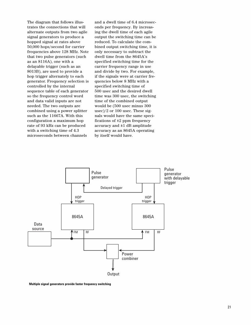
The diagram that follows illus-trates the connections that willalternate outputs from two agilesignal generators to produce ahopped signal at rates above50,000 hops/second for carrierfrequencies above 128 MHz. Notethat two pulse generators (suchas an 8116A), one with adelayable trigger (such as an8013B), are used to provide ahop trigger alternately to eachgenerator. Frequency selection iscontrolled by the internalsequence table of each generatorso the frequency control wordand data valid inputs are notneeded. The two outputs arecombined using a power splittersuch as the 11667A. With thisconfiguration a maximum hoprate of 93 kHz can be producedwith a switching time of 4.3microseconds between channels
and a dwell time of 6.4 microsec-onds per frequency. By increas-ing the dwell time of each agileoutput the switching time can bereduced. To calculate the com-bined output switching time, it isonly necessary to subtract thedwell time from the 8645A’sspecified switching time for thecarrier frequency range in useand divide by two. For example,if the signals were at carrier fre-quencies below 8 MHz with aspecified switching time of 500 usec and the desired dwelltime was 300 usec, the switchingtime of the combined outputwould be (500 usec minus 300usec)/2 or 100 usec. These sig-nals would have the same speci-fications of ±2 ppm frequencyaccuracy and ±1 dB amplitudeaccuracy as an 8645A operatingby itself would have.
21
HOPtrigger
FM RF FM RF
HOPtrigger
Delayed trigger
Powercombiner
Output
Datasource
8645A 8645A
Pulsegeneratorwith delayabletrigger
Pulsegenerator
Multiple signal generators provide faster frequency switching
Frequency accuracy ofagile outputs
The frequency accuracy and sta-bility of the 8645A is directlyrelated to the 10 MHz timebaseused as a reference for non-agileoperation. The output accuracyis a direct multiple of the time-base error. For the high stabilitytimebase specified at 0.0005parts per million (ppm) agingrate per day, the worst caseerror of a 1 GHz output after 10days would be 5 Hz assuming noinitial inaccuracy.
For frequency agile outputs, the8645A specifies a maximumerror of ±2 ppm. There are twocontributors to the frequencyerror: timebase error and tem-perature related drift. Timebaseerror is a factor because duringthe “learn” operation the 8645Abriefly synthesizes each outputfrequency using the phase lockloop circuits and reads voltagelevels of the VCO tuning line.While hopping this tuning volt-age is sent back to the VCO tocreate the output signal veryrapidly. Any error of the time-base will be reflected in the tunevoltage sent to the VCO used forfast hop signals.
Temperature related frequencyerrors result from a change inthe operating temperature of thecomponents in the agile signalpath. Several steps have beentaken to reduce the temperaturevariations within the instrumentsuch as providing constant-tem-perature heating of the delayline and temperature regulatingthe fan speed that provides cool-ing. These design features andthe large thermal mass of theinstrument greatly reduce thesensitivity of the 8645A’s agilefrequency accuracy to ambienttemperature changes. In anycase, it is recommended that theuser re-learn the hop frequen-cies before beginning a frequen-cy agile test. Each learnoperation will remove any tem-perature related offset betweenthe fully synthesized calibratingsignal and the agile output. Also,as noted in the specificationstable, having the unit plugged-infor 24 hours and operating for aminimum of 2 hours before thelearn operation and frequencyhopping begin, will ensure theheating elements and the ther-mal mass of the instrument areat a stable operating tempera-ture.
The typical worst case frequencyerror of ±1 ppm for agile fre-quency outputs can be signifi-cantly improved if the testparameters for the applicationare within a certain criteria thatminimizes the minute thermalvariation of the agile compo-nents themselves. For example,tests conducted during the8645A’s design show that thefrequency error is reduced foragile test sequences of less thanapproximately 60 unique fre-quencies with hop rates ofgreater than 10 hops/second.The same improvement occursfor internally controlledsequences having up to the max-imum number of 2400 uniquefrequencies as long as the distribution of how often eachfrequency is output is pseudo-random. The average frequencyerror measured under these con-ditions was less than ±0.3 ppm.
22
Relating phase error andfrequency accuracy
The quality of a signal can bespecified in many ways includingamplitude accuracy, spectralpurity, output level, modulationdistortion, etc. A common speci-fication of many sources is fre-quency accuracy or phase error.While many signal generators arespecified in terms of frequencyaccuracy, other types of sourcesare just as commonly describedwith a phase error. Since the sig-nal generator is often used tosimulate or substitute for asource specified in terms ofphase error, it becomes neces-sary to convert between frequen-cy accuracy and phase error todetermine if performance is suf-ficient. This calculation is of crit-ical importance for frequencyagile sources that are specified tobe within a stated frequencyaccuracy or phase error in a cer-tain amount of time after a fre-quency change is triggered. Thisproduct note discusses the con-version between phase error andfrequency accuracy.
Converting a phase error specifi-cation to a frequency accuracynumber is based on a keyassumption: that the phase set-tling characteristics are approxi-mately linear. Since the rate ofphase change of a signal is relat-ed to its frequency, knowing thata source’s output is uniformlyapproaching the desired finalphase state allows a calculationof the corresponding frequencychange. If the phase settlingdeparts significantly from linear,the calculated frequency errorwill be too low for faster phasesettling and too high for slowersettling signals. The followingexamples use typical characteris-tics for a frequency agile localoscillator to illustrate the phaseerror to frequency accuracy con-version process.
Example 1: Converting phaseerror to frequency accuracyA local oscillator switching inthe range of 800 to 1000 MHz isspecified to be within 0.1 radianof final phase 20 usec after thefrequency change trigger isreceived. The signal settles to thefinal phase during the 5 usecduration of the output.Converting the accumulatedphase error over the 5 usecduration results in a calculationof (0.1 radians)/(5 usec) equal-ing 20,000 radians/second thatthe signal is changing. Thisequals a frequency error of(20,000 rad/sec)/(2*pi rad/sec)or 3183 Hz. The frequency accu-racy of the 8645A is specified at±2 ppm of the carrier whichtranslates to a maximum of 2 kHzfrequency error for the 800 to1000 MHz frequency range. Inthis application the 8645A cansubstitute for the local oscillatoras far as the frequency accuracyrequirement is concerned.
If in the previous example thesignal settled to its final phasefaster than 5 usec, the calculatedfrequency error would be corre-spondingly higher. Anotherexample follows which convertsthe frequency accuracy of the8645A to its correspondingphase error for the previousexample.
Example 2: Converting frequency accuracy to phase errorThe frequency accuracy of the8645A is specified at +2 ppm ofthe carrier frequency. For a 1 GHzoutput this equals a maximumerror of 2 kHz. Converting 2 kHzto a phase error equals (2000Hz)*(2*pi rad/sec) or 12,566radians/sec. In the 5 usec dura-tion of the signal described inexample 1, the maximum accu-mulated phase error is (12566rad/sec)*(5 usec) or 0.0628 radians.
If the phase error is specified interms of degrees the valuesgiven in radians in the aboveexamples should be multipliedby (2*pi). In example 2 the8645A’s phase error of 0.0628radians translates to 0.3946degrees.
23
Amplitude dynamic rangewhile frequency hopping
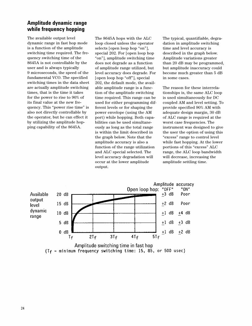
The available output leveldynamic range in fast hop modeis a function of the amplitudeswitching time required. The fre-quency switching time of the8645A is not controllable by theuser and is always typically 9 microseconds, the speed of thefundamental VCO. The specifiedswitching times in the data sheetare actually amplitude switchingtimes, that is the time it takesfor the power to rise to 90% ofits final value at the new fre-quency. This “power rise time” isalso not directly controllable bythe operator, but he can effect itby utilizing the amplitude hop-ping capability of the 8645A.
The 8645A hops with the ALCloop closed unless the operatorselects [open loop hop “on”],special 202. For [open loop hop“on”], amplitude switching timedoes not degrade as a functionof amplitude range utilized, butlevel accuracy does degrade. For[open loop hop “off”], special202, the default mode, the avail-able amplitude range is a func-tion of the amplitude switchingtime required. This range can beused for either programming dif-ferent levels or for shaping thepower envelope (using the AMport) while hopping. Both capa-bilities can be used simultane-ously as long as the total rangeis within the limit described inthe graph below. Note that theamplitude accuracy is also afunction of the range utilizationand ALC special selected. Thelevel accuracy degradation willoccur at the lower amplitudeoutput.
The typical, quantifiable, degra-dation in amplitude switchingtime and level accuracy isdescribed in the graph below.Amplitude variations greaterthan 20 dB may be programmed,but amplitude inaccuracy couldbecome much greater than 5 dBin some cases.
The reason for these interrela-tionships is, the same ALC loopis used simultaneously for DCcoupled AM and level setting. Toprovide specified 90% AM withadequate design margin, 30 dBof ALC range is required at theworst case frequencies. Theinstrument was designed to givethe user the option of using this“excess” range to control levelwhile fast hopping. At the lowerportions of this “excess” ALCrange, the ALC loop bandwidthwill decrease, increasing theamplitude settling time.
24
Amplitude shaping ofagile outputs
As part of their frequencyswitching algorithms, many fre-quency agile radios reduce theRF carrier power when switch-ing between frequencies. Sincecontrolling the characteristics ofthe amplitude transitions whileswitching is critical to properhopped operation, the 8645Awas designed to allow the userto shape the amplitude transi-tions of the RF carrier while infast hop operation.
If the amplitude transitions arevery sharp in nature, a frequen-cy agile carrier (when viewed atone specific frequency) will havethe same sin (X/X) spectral sig-nature as a pulsed RF carrier. Aswith a pulsed RF carrier, theenergy of the carrier will be dis-tributed throughout the lobes ofthe sin (X/X) envelope. Thisenergy distribution is typically ofno concern in pulsed applica-tions but in frequency agileapplications the distributedenergy can fall into adjacentcommunication channels, caus-ing disruption of communica-tions in those channels. To avoidthis problem, frequency agileradios that reduce the RF carrierpower when switching alsoshape the RF power transitionsto minimize the spectral splatterassociated with sharp (pulselike) amplitude transitions.
When in fast hop operation, the8645A automatically ‘softens’the amplitude transitions todecrease the spectral splatter. Aspower is being shut off at a spe-cific hop frequency, timers builtinto the instrument send a nega-tive step to the ALC loop so thatthe amplitude drops at a ratethat is consistent with the ALCloop bandwidth. After severalmicroseconds the ALC loop willhave decreased the output ampli-tude by approximately 30 dB. Atthis point the pulse modulator isactivated to get an additional 35dB or more of amplitudedecrease. This timing sequenceis reversed when the power isbeing brought up at the new fre-quency, with the pulse modula-tor being turned off first andthen the ALC loop being allowedto return to its pre-shutoff level.This sequence greatly reducesthe spectral splatter from what itwould be if only the pulse modu-lator were used. If the user acti-vates special function 202 ALCoff, to get slightly faster frequen-cy switching speed, the ALC isnot used to decrease the outputpower. Only the pulse modulatorwould be used so spectral splat-ter increases somewhat due tothe more abrupt amplitude tran-sition. Additionally the power isonly decreased approximately 35dB between frequency hops.
The operator that would like touse the 8645A to emulate atransmitter that uses a rigorousamplitude shaping technique, orwho needs to decrease spectralsplatter for other reasons, canuse the external DC AM port toshape the amplitude transitionsduring fast hop operation. Theshaping signal, such as a raisedcosine wave, when input into theexternal DC AM port controlsthe ALC loop to implement theamplitude shaping. To shape theamplitude rise and fall charac-teristics of a hopped signal, theshaping signal must be synchro-nized to the hop trigger or dwelltime control (available on therear panel of the 8645A). Itshould be noted that externalshaping, as well as the automaticshaping previously described,use some of the available ALCrange. This means that theamount of amplitude variationavailable while hopping isdecreased. Elsewhere in thisproduct note the interactionbetween amplitude hoppingrange, frequency switchingspeed, and amplitude shaping isdiscussed as “Agile AmplitudeDynamic Range”.
25
Modulation
High rate, high deviationfrequency modulation
The 8645A has overcome manyof the previous barriers to pro-vide FM with high deviation inan RF signal generator. By usingdigital techniques, deviations ashigh as 10 MHz are possible forcarrier frequencies in the maincarrier band of 515 to 1030 MHz.Accompanying this breakthroughin high deviation FM is a similarincrease in the maximum rate ofFM to 10 MHz. One reason forthis extra FM performance is toensure sufficient usable capabili-ty after the many divider stagesthat extend frequency coveragedown to the minimum carrieroutput of 252 kHz.
In the 8645A, the amount of FMdeviation selected determinesthe length of the delay line usedin the delay line discriminatorplaced around the VCO toreduce phase noise. At higherselected FM deviations the delayline is shortened so that it doesnot reduce FM sensitivity in thedeviation range that is set. Witha shorter delay line the phasenoise from the VCO increases,but generally this is acceptablefor applications needing high FMdeviations. The annunciator forthe mode 1 key on the frontpanel lights up when the shorterdelay line is in use. As FM devia-tion is reduced below approxi-mately 17% (1.76 MHz in themain band) of the maximumallowed at each carrier band, theextra delay line is automaticallyplaced in the VCO signal pathunless the user has specificallylocked the instrument into mode1 using the mode select keys.Phase noise and spurs arereduced for operation using thesmaller FM deviation and themode 2 indicator is lit. In thisway, the best spectral purity isprovided for any FM deviationthat is selected.
The 8645A has two differenttypes of FM referred to as digi-tized FM and linear FM, both ofwhich can be used with theinternal modulation oscillatorand/or an external source at thefront panel. Digitized FM is thedefault type and utilizes an A/Dconverter to translate the modu-lating waveform into digitalinformation that is used to mod-ulate the fractional-N divider
number. This provides FM atrates from DC up to the phaselocked loop bandwidth alongwith the capability for high devi-ations. A wideband, high slewrate analog path sums the modu-lation signal onto the VCO tuneline to allow FM at rates fromthe PLL bandwidth up to 3.75 MHz and typically to 10 MHz while retaining the highdeviations.
Linear FM is activated using spe-cial function 120. In this FMoperation the digital path isswitched out leaving just theanalog path for improved flat-ness and stereo separation. Inmode 2 with linear FM, the PLLis not used and linear DCFM isavailable through the frequencylocked loop. During calibration,offsets are nulled in this path toimprove frequency accuracy infast hop operation which alwaysuses linear FM. Group delay isless than 1 usec in linear FMwith a typical value of 0.1 usec.
The maximum deviation avail-able is the divided result of theamount available in the mainband of 515 to 1030 MHz. Themaximum of 10 MHz deviation inthis main band becomes 5 MHzin the first divide band of 207.5to 515 MHz. The minimum devia-tion that can be set is 100 Hz inthe main band and also getshalved by each divider band to aminimum of 1 Hz. The maximumavailable FM rate is also reducedby each divider section due tothe half-octave filters present ineach divider section to reducethe level of harmonics generated.
26
Simultaneous modulation
The 8645A has a wide range ofcombinations available for simul-taneous modulation. Variouscombinations of amplitude, fre-quency, phase and pulse modula-tion are provided as follows:
With AM: FM, phase, pulse, FM and pulse, phase and pulse
With FM: AM, pulse, AM and pulse
With phase: AM, pulse, AM and pulse
With pulse: AM, FM, phase, AM and FM, AM and phase
In addition to these combina-tions, the modulating waveformcan be provided from either theinternal modulation source orfrom an external source via afront panel input The internal/external status of a given modu-lation type can be set independ-ent from any other modulationtype that may also be active. Thefollowing combinations of inter-nal and external modulationwaveform source are availablefor each modulation:
AM: Internal, external FM: Internal, external, internal
and external Phase: Internal, external,
internal and external Pulse: External only
In simultaneous internal andexternal FM or phase modula-tion, an external signal of typi-cally 30% or more of full scaleinput can be applied simultane-ously with a full scale internalsignal without any limitingoccurring.
When using the internal modula-tion source, rates from .1 Hz to400 kHz are available with a res-olution of .1 Hz. Therefore theentire bandwidth of AM (100 kHz for carrier frequenciesgreater than 128 MHz) andphase modulation (150 Hz) aswell as a major portion of theFM bandwidth can be coveredwith the internal modulationsource. The level of the internalmodulation signal can be adjust-ed with a resolution of .2% of fullscale to provide improved reso-lution of level of various modula-tion types. The internalmodulation source can also pro-vide complex waveforms such assawtooth and squarewave atrates up to 50 kHz and whiteGaussian noise of constantamplitude from .1 Hz to 400 kHz.
The external modulation sourceinput of all modulation typesexcept pulse can be set to ACcoupling as an alternative to DCcoupling. In AC coupling all DCdrifts and biases up to ±10 voltsfrom external sources areblocked without degradation ofperformance. The lower 3 dBbandwidth in AC coupling for allmodulation types is typically 20 Hz.
The input impedance of all theexternal modulation ports is 600 ohms, except the FM port.The external FM input imped-ance is 50 ohms to allow exter-nal modulation sources toprovide signals up to 10 MHzwith low loss. By activating spe-cial function 123 the user canroute modulation signals fromthe phase modulation input tothe FM circuitry. Since the phasemodulation input impedance is600 ohms, this capability pro-vides higher input impedance forFM operation. The upper 3 dBFM bandwidth using this phasemodulation input is approxi-mately 2 MHz.
27
Digitized FM operation
Synthesized signal generatorshave traditionally generated FMwith a phase lock loop dedicatedfor this purpose. For AC coupledFM, this loop remains lockedwhile the frequency modulatingsignal is injected into the loop toFM the output. For DC coupledFM, the loop must be unlockedso that low modulating frequen-cies are not canceled by the loopfeedback. However, unlockingthe loop for DC FM allows theoutput frequency to drift, whichcan be a problem for some appli-cations. The 8645A has this tra-ditional implementation of FMoperation as a special function(120). The standard FM imple-mentation for the 8645A is onethat removes the frequency driftproblem of DC FM.
As standard operation, the8645A uses a digital FM signal tomodify the instantaneous syn-thesizer divide values in thefractional-N circuit. This methodgreatly reduces the frequencydrift and offset that is usuallyassociated with DC FM opera-tion. The only remaining drift isrelated to the Analog to DigitalConverter (ADC) which is typi-cally much less than the drift ofan open loop VCO. This modula-tion technique is also very accu-rate at low FM rates because theoutput of an ADC can be muchmore precise than the analogtuning curve of a VCO. A sidebenefit of major importance isthat this technique does notintroduce out-of-channel spurs.In a traditional signal generatorblock diagram, the FM loopneeds to sum into the main loopwith the unavoidable introduc-tion of crossing spurs.
There are some disadvantages tothis digitized FM technique. Oneis that the digitization and sum-mation of the modulating signaltakes time, resulting in approxi-mately 30 usec of group delay ofthe modulating signal at ratesinside the PLL bandwidth. Thenon-flat group delay may causedistortion of the modulating sig-nal, and in some instances mayactually cause the PLL to unlock.Another implication of this mod-ulation scheme is that when digi-tal FM is being used in afeedback loop, the quantizationsteps of the ADC may causephase discontinuities. For thesereasons some applications mayrequire use of the traditional FMimplementation available as spe-cial function 120.
The following describes the per-formance that results from acti-vating each type of FM in the8645A.
Center frequency accuracy andtemperature stability: For the digitized FM mode, theinitial center frequency accuracyis typically 0.1% of the FM devia-tion set (typically 1% if in fasthop mode). Non-digitized or lin-ear FM (special 120) has an off-set of typically 1 kHz for anydeviation in the 515 to 1030 MHzcarrier band (offset divides forlower carrier bands.) The carrierfrequency temperature drift withdigitized FM active is typicallyless than 0.1% of the set devia-tion over the full operating rangeof 0 to 55 ˚C. The center fre-quency accuracy in linear FMwill vary approximately 1 kHz/˚C in the 515 to 1030 MHz carri-er range.
Phase noise variations at lowoffsets: For deviations less than 5% ofthe maximum deviation availableat any carrier frequency, digi-tized FM operation negligiblyaffects the phase noise perform-ance of the output. The noiseincreases with higher FM devia-tions. For linear FM, the phasenoise at low offsets goes up by20 dB when activated but doesnot increase as much for higherdeviations as it does in digitizedFM. In general, special 120 linearFM may improve phase noiseperformance over the digitizedFM at offsets less than 10 kHzwhen deviations greater than 20 kHz are in use. The topic“Phase Noise Performance” inthis product note has moreinformation on this subject.
FM deviation accuracy: For modulation rates <1 kHz,deviation accuracy for the digi-tized FM is a function of theADC, typically <1% of the setdeviation. For linear FM it isapproximately 5%. At higherrates, the deviation accuracy isdependent on analog factorswhich makes it the same foreither FM technique.
Square wave or digital modulation waveforms: For linear FM the group delay isvery flat and typical of other sig-nal generators. The group delayof digitized DC FM is a functionof the modulating rate. For sin-gle-tone modulation signals or ifthe spectral energy is primarilybelow 10 kHz, group delay in dig-itized FM operation is constantand will not affect the outputsignal. For high rate or digitalmodulating signals, the variablegroup delay of digitized FMcould cause serious distortion solinear DC FM should be selected.
28
AC coupled FM
This product note builds on theinformation given in the digi-tized FM operation product noteto explain the operation andresulting performance of ACCoupled FM (ACFM).
The 8645A has digitized and lin-ear ACFM capabilities. DigitizedACFM is simply AC coupling ofthe digitized DCFM described inthe “Digitized FM Operation”product note. The default digi-tized DC Coupled FM (DCFM)utilizes an Analog-to-DigitalConverter (ADC) to digitize theincoming modulating signal as itoccurs and uses the digitizedinformation to modify the syn-thesis dividers. Low frequency 3 dB bandwidth of digitized
ACFM is approximately 7 Hz.This function should satisfymost applications if the slightfrequency inaccuracy of approxi-mately .1% of the programmeddeviation can be tolerated. Caremust be exercised that the com-plexity of the modulating wave-form does not cause unlockingor distortion problems asexplained in the “Digitized orLinear FM” product note. Due tothe very low drift of the digitizedDCFM operation in the 8645A,there is less use for digitizedACFM. It should be noted thatthe 50 ohm input impedance toground of the external FM inputwill be still there for ACFM signals.
The 8645A also offers specialfunction 120 to get linear ACFM.This mode is more typical of theACFM in other signal generatorswith the modulating signal inputdirectly to the VCO except thatthe phase lock loop that is mod-ulated has a much wider band-width than is typical. Because ofthis, the 3 dB low frequency cor-ner is either 300 Hz or 3 kHz,depending on whether mode 2 or1 respectively of the mode selectkeys is lit. If the user can toler-ate this relatively high 3 dB fre-quency corner, the benefits thisoperation includes minimalgroup delay and precise centerfrequency. The applicationswhere linear ACFM may be use-ful are when any frequency inac-curacy can’t be tolerated, or thegroup delay characteristics ofthe digitized FM can’t be tolerat-ed, or unlocking occurs due tosquare waves at the FM port.
29
Special Capabilities
Tailored operation throughspecial functions
In addition to the featuresdirectly available to a userthrough the front panel keys, the8645A has a number of capabili-ties called “special functions”.These functions are accessedwith the [Special] key in the util-ity field on the front panel andallow a user to customize opera-tion of the instrument for a spe-cific application.
Special functions or “specials”are functionally grouped bynumber as follows:
To find a particular special in thelist, the user can scroll throughthe list by pressing [Special] andeither turning the knob or press-ing the up or down arrow keys.When the display shows thedesired special, pressing [Enter]will access that special. A usermay also press [Special] followedby the number of the special and[Enter] to access it. Pressing[Special] [Enter] will re-accessthe last special displayed. Once aspecial is accessed, it can be con-trolled with the same keys usedfor control of standard functions.
When displaying a special, thelight above the special key willbe lit if it is not at its default set-ting (the special is active). Whilescrolling through the specials asdescribed above, the light willalso come on when displayingthe name of an active special.When no special is being dis-played and standard functionsare being used or displayed, thislight will be lit if there are anyspecials active. Pressing the[Display] key followed by the[Special] key will show a list ofall active specials.
30
100-109: Amplitude & ALC functions110-119: Carrier control (phase, frequency multiplier, sweep mode)120-129: FM functions130-159: Audio source control160-169: Frequency reference170-189: Tests, calibration, security, volt/power meter functions.190-199: Serial number, display control200-210: Fast hop functions
Protecting classifiedinstrument settings
The 8645A incorporates a num-ber of functions to prevent theunauthorized exposure of classi-fied instrument settings andreadouts. They range from blank-ing the displayed readouts, to anautomatic memory erasure ifpower to the instrument is inter-rupted.
The simplest function which hasbeen present on many instru-ments for some time now is dis-play blanking. With the 8645A,the entire display or specificfunctional readouts such as fre-quency or modulation can beblanked either from the frontpanel by activating special func-tions or using HP-SL commandsvia GPIB. This blanking includesall annunciator lights on thefunction specific keys as well asthe alpha-numeric display. Thiswill prevent the casual observerfrom seeing the instrument set-tings. To prevent an operatorfrom unblanking the display bydeactivating the special functionanother security-related capabil-ity, the local lockout can be initi-ated over GPIB. With locallockout active the instrument
keyboard will not respond to theuser until the controller removesthe local lockout over the GPIBor until power is cycled. If poweris cycled the machine returns towhatever state it was in beforepower was turned off, exceptthat local lockout will be dis-abled.
A function called RAM wipe wascreated to allow the user toerase all user entered parame-ters and operation specific cali-bration data from the internalRAM. When this special function172 is activated, a power-onreset is performed on the instru-ment. All RAM locations arecleared and tested with checker-board patterns, and then clearedagain. A side effect of this opera-tion is that the instrument mustspend a few minutes re-calibrat-ing itself in order to restore thecalibration coefficients in RAM.All storage registers are cleared,all fast hop sequence and chan-nel data are also cleared. Thisfeature satisfies the require-ments set forth in Mil Std380-380.
The three functions described sofar, blanking, local lockout, andRAM wipe, can be used in com-bination with the security modefunction for the highest level ofsecurity. Security mode specialfunction 173, is like a one wayoperation in that no reduction ofsecurity is allowed, only increas-es. Activating security mode setsa flag in the instrumentfirmware such that all or part ofthe display can be blanked butnot unblanked. If an instrumentpreset is performed, the instru-ment will remain in its currentstate of operation, with displaysblanked and keyboard disabled ifpreviously set, and the securitymode still active. Security modecan be deactivated by turningspecial function 173 off orthrough an GPIB command.However, leaving security modeeither way automatically andimmediately initiates a RAMwipe operation. If power iscycled with security mode activea RAM wipe will be performedimmediately when power isrestored and the security modewill be deactivated. With securi-ty mode active the user can stillgain control of the instrument,but not with any classified dataparameters still present on thedisplay or in memory.
31
Storage registers andsequential recall
Storage registers are used tostore the current state of themachine for later recall. Thereare 50 storage registers providedin the 8645A. The storage regis-ters use non-volatile memory sopower interruptions won’t affectthe contents. Instrument presethas no effect on the storage reg-isters, but activating the RAMwipe special function to removeall user-entered data from theinstrument will erase them.Storage registers 0 through 9store the entire machine stateexcept for the fast hop channeldata. (The fast hop channelinformation is held innon-volatile memory also, sopower interrupts won’t force areload.) Registers 10 through 49store only the current frequencyand amplitude (frequency off-sets/multipliers or amplitude off-sets are not included). Any ofthe 50 storage registers can berecalled explicitly by specifyingthe register number.
Machine states are saved usingthe front panel keys by pressing[Save] <register number>(Enter]. To recall a register,press [Recall] <register number>[Enter]. All of the storage regis-ters can be erased at once bypressing [Clear all] [Enter].
Registers can also be recalled ina user-defined sequence that hasthe instrument repetitively step-ping from one register to anoth-er. Registers 0 through 9 can beincluded in the sequence listthat can be up to 10 registerslong including any repeated reg-isters. A sequence is entered bypressing [Set seq] <first registernumber.> [Enter] <second regis-ter number> [Enter] ... continueto ... <last register number>[Enter]. There are several waysto recall registers from asequence list. To repetitivelyrecall the entire sequence, press[Auto seq]. Pressing [Off] stops
this sequentially recall. To recalleach sequence entry individual-ly, either press [Seq] on the frontpanel or provide a +5 volt triggersignal to the Seq input on therear panel. The entire sequencelist in memory can be displayedby pressing [Display] [Seq].
Each of the functions describedabove has its counterpart HP-SLcommand for control over GPIB.
32
Offsets and multipliers offrequency and amplitude
The 8645A has several featureswhich allow the user to stream-line use of the instrument inapplications where the frequen-cy or amplitude of the instru-ment is scaled or offset by theuser. This change of amplitudeor frequency may be due to anamplifier, attenuator, cable,mixer, multiplier, divider, etc.For some applications, it may bemore useful to control and dis-play the frequency and ampli-tude in terms of a device’soutput rather than the RF out-put of the signal generator.
Amplitude offset allows the userto program into the 8645A theamount of loss or gain in theconnecting device. For example,to control and display the ampli-tude at a device’s input after aconnecting cable loss of 1.2 dB,the user would press [Amptdofs] <–1.2> [dB]. If the displaypreviously read 0 dBm it willnow read –1.2 dBm with anadditional indicator “Offset”showing that an offset is in use.An offset to reflect the output ofa 20 dB amplifier would beentered [Amptd ofs] <20> [dB].The 0 dBm display would changeto +20 dBm by these entries. Allsubsequent amplitude settingsentered into the instrument willbe displayed according to thenew amplitude reference point.For example, entering an ampli-tude value of +5 dBm into the8645A with a +20 dB offsetactive to reflect the output of anamplifier would actually produce–15 dBm at the RF output of thesignal generator. In all cases,losses are entered as negativenumbers and gains as positiveentries. The maximum amplitudeoffset range is ±50 dB. Pressing[Amptd ofs] [Off] turns off anamplitude offset.
Frequency offset allows the userto enter a frequency shiftbetween the RF output and thedisplay of the 8645A to reflectthe result of the signal passingthrough an external device. Theoperation of a frequency offset issimilar to that of an amplitudeoffset. For example, if the userwants to produce an output thatwill be translated by a mixingprocess upward by 2 GHz andhave the display reflect theresult of the frequency transla-tion, pressing [Freq ofs] <2> [GHz] will do it. All subse-quent frequency entries willreflect the offset, ie. entering a 3 GHz frequency setting with the2 GHz offset active will result ina 1 GHz signal coming from theRF output of the signal genera-tor. A display that previouslyread 1 GHz will then read 3 GHzto reflect the output of the mix-ing process and the “Offset” indi-cator will be lit. Negative entriescan be used to shift the RF out-put for a down-convertingprocess. Frequency offsets arelimited to ±50 GHz. To turn off afrequency offset, press [Freq ofs][Off].
Frequency multiplier allows theuser to enter a multiplier or divi-sor to modify the frequency out-put of the 8645A to reflect theaction of a multiplier or dividerconnected to the signal genera-tor. Frequency multipliers areentered using special function111. For example, if an externaldevice multiplies the signal byfour, then pressing [Special]<111> [Enter] <4> [Enter] willproduce an RF output that when
multiplied by four will equal theentered frequency setting. Thefrequency display will show thefrequency at the output of themultiplier. An “Offset” indicatoris lit below the frequency read-out. Any subsequent frequencyentries will be in terms of theentered multiplier and not theactual output of the generator,ie. entering 1 GHz with a multi-plier of 4 active will produce a250 MHz signal at the RF outputfor multiplication to 1 GHz.Similarly, negative entries reflecta divider’s action. A multiplierrange of ±10 can be entered andonly integer values are allowed.To disable the multiplier func-tion, press [Special] <111>[Enter] <1> [Enter] which resetsthe frequency display for a mul-tiple of 1.
When using a frequency multipli-er, the FM deviation is scaled inthe same way as the carrier fre-quency since an external multi-plier or divider also multipliesor divides the amount of FMdeviation. Therefore, if a multi-plier of four was active in the8645A, an entered FM deviationof 10 MHz would actually pro-duce a 2.5 MHz deviation on theactual output of the signal gener-ator and a displayed value of 10 MHz. Frequency offsets haveno effect on FM.
Offsets and multipliers may beused simultaneously. Whenusing both a frequency multipli-er and a frequency offset, thedisplayed frequency equals (theoutput frequency) times (themultiplier) plus (the offset).
33
Built-in calibration functions
The 8645A was designed with nomanual internal adjustments. Alladjustments are under the con-trol of the instrument firmwareresponding to a variety of sen-sors placed at strategic locationsto monitor signal levels. Thisallows the instrument to adjustits signal parameters for an opti-mum output whenever the userwants. With this capability, theinstrument can effectively cali-brate itself by making adjust-ments to signal levels andrecording the settings that resultin the optimum and specifiedoutput signal. This calibrationdata is stored in battery back-upRAM so that the user will nothave to repeat the calibrationwhenever the instrument isturned on. The self-calibrationprocess typically takes approxi-mately 2 minutes.
If the user suspects that theinstrument is not performingcorrectly, a re-calibration of theinstrument may be initiated bypressing [Special] <171> [Enter][On] from the front panel or bysending the “*CAL?” HP-SL com-mon query over GPIB. Theinstrument will display a resultcode of 0 if no errors occurredduring the calibration operation.
The internal temperature is con-stantly monitored by the instru-ment to insure the optimumcalibrated output. Since portionsof the calibration data are tem-perature sensitive, the instru-ment will store the currenttemperature when calibratingalong with the calibration data.If the temperature changesenough (approximately 10degrees centigrade) to potential-ly invalidate the calibrationdata, a warning will be placed inthe message queue to notify theuser. If the user feels that theinstrument performance is notsatisfactory, the instrument maybe re-calibrated at the new tem-perature using the special func-tion.
Under certain conditions the cal-ibration data may be lost orbecome corrupt, such as due tothe following events:
1. Disabling the RAM using a switch on the Digital Control Unit (DCU).
2. Executing the RAM wipe special function.
3. Turning off the security function (which executes the RAM wipe function).
4. Failing a self-calibration or diagnostic test.
5. Removing the DCU from the motherboard.
If the instrument powers upwithout valid calibration data, itwill automatically initiate aself-calibration. The exception tothis is when the service modeswitch on the DCU is enabled toprevent nuisance calibrationswhile working on an incompleteinstrument.
34

Finding failures withinternal diagnostics
The 8645A contains diagnosticroutines in the instrumentfirmware which test the instru-ment hardware and will reportover 90% of all instrument fail-ures that could occur. Thesediagnostic routines will also iso-late the cause of the failure to areplaceable hardware module ora cable. The diagnostic routinesare activated from the frontpanel using an instrument spe-cial function or via GPIB com-mands and only run wheninitiated by the user.
There is separate circuitry builtinto the instrument that continu-ally monitors high-level function-ality (such as the phase lockloop being locked) and will put amessage in the instrument mes-sage buffer should a problem bedetected. However, this messageis not specific enough to deter-mine which module is the causeof the problem. When the userreads the message, the diagnos-tic routines can be activated todetermine which hardware mod-ule is at fault.
There is special hardware in theinstrument that makes thesediagnostics possible. The digitalcontroller contains a voltmeterwith AC and DC measurementcapability and each of the hard-ware modules contains at leastone 8 channel multiplexerthrough which critical points onthe modules can be measured bythe voltmeter. A typical diagnos-tic routine would set a module toa specific operating mode andthen set the multiplexer on thatmodule so a critical point on themodule can be measured. Theroutine would compare the volt-meter reading with the normalvalue. If the reading is not with-in preset limits, the routine willterminate testing and a resultcode is displayed on the frontpanel of the instrument indicat-ing where in the test sequencethe failure occurred. If the read-ing is normal, the routine contin-ues to set the module to all itsoperating conditions and meas-ures critical circuit points foreach set of conditions. A typicalroutine makes 100 measure-ments on a module.
The diagnostic routines can findalmost all-functional failures,however, the diagnostics are lim-ited in their ability to find fail-
ures where a performance valueis just out of spec. The internalvoltmeter has an accuracy ofapproximately 2% and this is notaccurate enough to measuresome internal signals to deter-mine if the specification is beingmet. However, these ‘out of spec’problems are historically a smallpart of total instrument failures.Another limitation is there areusually only 8 points on a mod-ule where measurements can bemade. These 8 points wereselected to maximize the amountof circuitry that can be tested,but there is still some circuitryon most modules that cannot betested. In general the diagnosticswill not find problems withphase noise, spurs, output levelaccuracy, high deviation FM andfast switching.
The service documentation avail-able with the PSG products con-sists of a diagnostics manual anda service manual. The diagnos-tics manual is needed to use thediagnostics. Its purpose is toguide the user to finding the badmodule and replacing it withanother module. The servicemanual contains schematic dia-grams and uses the result of thediagnostics to guide the user inrepairing the bad module to thebad component.
35
Agilent Technologies’ Test andMeasurement Support, Services, and AssistanceAgilent Technologies aims to maximize thevalue you receive, while minimizing yourrisk and problems. We strive to ensurethat you get the test and measurementcapabilities you paid for and obtain thesupport you need. Our extensive supportresources and services can help youchoose the right Agilent products for yourapplications and apply them successfully.Every instrument and system we sell has aglobal warranty. Support is available for atleast five years beyond the production lifeof the product. Two concepts underlieAgilent's overall support policy: "OurPromise" and "Your Advantage."
Our PromiseOur Promise means your Agilent test andmeasurement equipment will meet itsadvertised performance and functionality.When you are choosing new equipment,we will help you with product information,including realistic performance specifica-tions and practical recommendations fromexperienced test engineers. When you useAgilent equipment, we can verify that itworks properly, help with product opera-tion, and provide basic measurementassistance for the use of specified capabil-ities, at no extra cost upon request. Manyself-help tools are available.
Your AdvantageYour Advantage means that Agilent offersa wide range of additional expert test andmeasurement services, which you can pur-chase according to your unique technicaland business needs. Solve problems effi-ciently and gain a competitive edge bycontracting with us for calibration, extra-cost upgrades, out-of-warranty repairs,and on-site education and training, as wellas design, system integration, projectmanagement, and other professional engi-neering services. Experienced Agilentengineers and technicians worldwide canhelp you maximize your productivity, opti-mize the return on investment of yourAgilent instruments and systems, andobtain dependable measurement accuracyfor the life of those products.
By internet, phone, or fax, get assistancewith all your test & measurement needs
Online assistance:
www.agilent.com/find/assist
Phone or FaxUnited States:(tel) 1 800 452 4844
Canada:(tel) 1 877 894 4414(fax) (905) 282-6495
China:(tel) 800-810-0189(fax) 1-0800-650-0121
Europe:(tel) (31 20) 547 2323(fax) (31 20) 547 2390
Japan:(tel) (81) 426 56 7832(fax) (81) 426 56 7840
Korea:(tel) (82-2) 2004-5004 (fax) (82-2) 2004-5115
Latin America:(tel) (305) 269 7500(fax) (305) 269 7599
Taiwan:(tel) 080-004-7866 (fax) (886-2) 2545-6723
Other Asia Pacific Countries:(tel) (65) 375-8100 (fax) (65) 836-0252Email: [email protected]
Product specifications and descriptionsin this document subject to change with-out notice.
© Agilent Technologies, Inc. 2001Printed in USA July 18, 20015951-6712