Embed Size (px)
Citation preview

Agilent G6012A Quiet Cover DS
Service Manual
Agilent Technologies
Notices© Agilent Technologies, Inc. 2012
No part of this manual may be reproduced in any form or by any means (including electronic storage and retrieval or transla-tion into a foreign language) without prior agreement and written consent from Agilent Technologies, Inc. as governed by United States and international copyright laws.
Manual Part NumberG6012-90020
EditionFirst edition, July 2012
Printed in USA
安捷伦科技 (上海)有限公司 上海市浦东新区外高桥保税区 英伦路 412 号 联系电话:(800) 820 3278
WarrantyThe material contained in this docu-ment is provided “as is,” and is sub-ject to being changed, without notice, in future editions. Further, to the max-imum extent permitted by applicable law, Agilent disclaims all warranties, either express or implied, with regard to this manual and any information contained herein, including but not limited to the implied warranties of merchantability and fitness for a par-ticular purpose. Agilent shall not be liable for errors or for incidental or consequential damages in connection with the furnishing, use, or perfor-mance of this document or of any information contained herein. Should Agilent and the user have a separate written agreement with warranty terms covering the material in this document that conflict with these terms, the warranty terms in the sep-arate agreement shall control.
Safety Notices
CAUTION
A CAUTION notice denotes a hazard. It calls attention to an operating procedure, practice, or the like that, if not correctly performed or adhered to, could result in damage to the product or loss of important data. Do not proceed beyond a CAUTION notice until the indicated conditions are fully understood and met.
WARNING
A WARNING notice denotes a hazard. It calls attention to an operating procedure, practice, or the like that, if not correctly performed or adhered to, could result in personal injury or death. Do not proceed beyond a WARNING notice until the indicated conditions are fully understood and met.
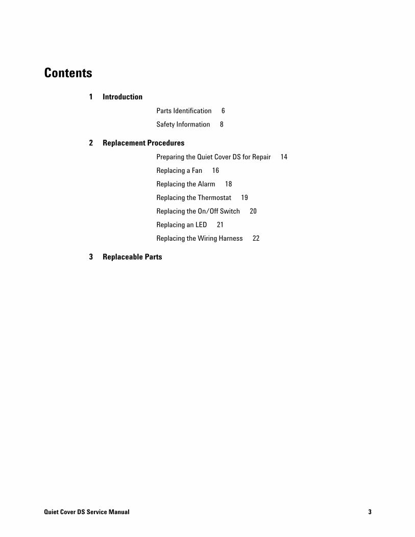
Contents
1 Introduction
Quiet Cover DS Service Manual
Parts Identification 6
Safety Information 8
2 Replacement Procedures
Preparing the Quiet Cover DS for Repair 14
Replacing a Fan 16
Replacing the Alarm 18
Replacing the Thermostat 19
Replacing the On/Off Switch 20
Replacing an LED 21
Replacing the Wiring Harness 22
3 Replaceable Parts
3

4
Quiet Cover DS Service Manual
Agilent G6012A Quiet Cover DSService Manual
1Introduction
Parts Identification 6
Safety Information 8
This manual provides information for Agilent service representatives to support the Agilent G6012A Quiet Cover DS.
The Quiet Cover DS is only compatible with Agilent DS 202, DS 302, DS 402, and DS 602 pumps.
5Agilent Technologies

1 Introduction
Parts Identification
6
Figures 1- 4 point out the main internal components of the Quiet Cover DS.
Figure 1 Quiet Cover DS (internal view of rear panel)
Fan cable
Fan connector
Thermostat5188-6570
Power connector(included in wiring harness)
Wiring harness5188-1163
Alarm5188-1277
FanG1099-60564
Figure 2 Quiet Cover DS (internal view of front panel)
Power (Green LED) 5188-1180
On/off switch 5188-1178
Ferrite G3199-60000(part of wiring harness 5188-1163)
Temperature alarm (Red LED )5188-1179
Q
uiet Cover DS Service Manual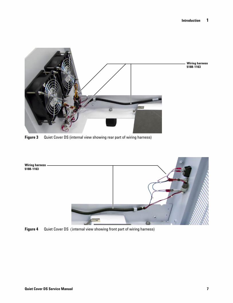
Introduction 1
Quiet Cover DS Service Manual
Figure 3 Quiet Cover DS (internal view showing rear part of wiring harness)
Wiring harness 5188-1163
Figure 4 Quiet Cover DS (internal view showing front part of wiring harness)
Wiring harness 5188-1163
7
1 Introduction
Safety Information
General Information
8
The Quiet Cover DS conforms to the International Electrotechnical Commission (IEC) 61010–1 safety standard.
It also conforms to the following regulations on Electromagnetic Compatibility (EMC) and Radio Frequency Interference (RFI):
• CISPR 11/EN 55011: Group 1, Class A
• IEC/EN 61326
• AUS/NZ
This ISM device complies with Canadian ICES- 001. Cet appareil ISM est conforme a la norme NMB—001 du Canada.
The Quiet Cover DS is designed and manufactured under a quality system registered to ISO 9001.
Information
The Agilent Technologies Quiet Cover DS meets the following IEC classifications: Category II, Pollution Degree 2, Class III.
Quiet Cover DS has been designed and tested in accordance with recognized safety standards and is designed for use indoors. If it is used in a manner not specified by the manufacturer, the protection provided by the instrument may be impaired. Whenever the safety protection of the Quiet Cover DS has been compromised, disconnect it from all power sources and secure it against unintended operation.
Refer servicing to qualified service personnel. Substituting parts or performing any unauthorized modification to the instrument may result in a safety hazard.
Quiet Cover DS Service Manual
Introduction 1
Quiet Cover DS Service Manual
Symbols
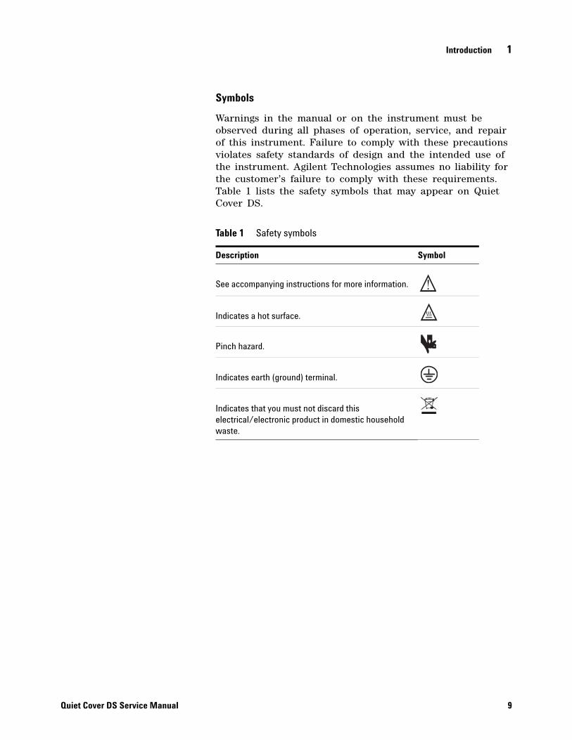
Warnings in the manual or on the instrument must be observed during all phases of operation, service, and repair of this instrument. Failure to comply with these precautions violates safety standards of design and the intended use of the instrument. Agilent Technologies assumes no liability for the customer’s failure to comply with these requirements. Table 1 lists the safety symbols that may appear on Quiet Cover DS.
Table 1 Safety symbols
Description Symbol
See accompanying instructions for more information.
Indicates a hot surface.
Pinch hazard.
Indicates earth (ground) terminal.
Indicates that you must not discard this electrical/electronic product in domestic household waste.
9
1 Introduction
Important Safety Warnings
10
Safety cautions and warnings must be observed during all phases of operation, service, and repair of Quiet Cover DS. Failure to comply with these precautions violates safety standards of design and Quiet Cover DS’s intended use. Agilent Technologies assumes no liability for the customer’s failure to comply with these requirements.
WARNING Never run the pump without also running Quiet Cover DS.
CAUTION While running Quiet Cover DS:
• Do not block air flow to the fans.
• Do not set items on top of Quiet Cover DS.
• It is important that the Quiet Cover DS not recirculate hot air. Always position the front end of the Quiet Cover DS where it can draw cool air.
Be sure to position Quiet Cover DS so that there is plenty of room to
CAUTIONallow access to panels and controls.In the event of a temperature alarm malfunction or if the alarm has
WARNINGbeen on for an extended period of time, Quiet Cover DS and the pump may be dangerously hot. Check that the Quiet Cover DS and pump are cool before you touch them.Quiet Cover DS Service Manual

Introduction 1
Quiet Cover DS Service Manual
Electromagnetic compatibility
This device complies with the requirements of CISPR 11. Operation is subject to the following two conditions:
• This device may not cause harmful interference.
• This device must accept any interference received, including interference that may cause undesired operation.
If this equipment does cause harmful interference to radio or television reception, which can be determined by turning the equipment off and on, the user is encouraged to try one or more of the following measures:
• Relocate the radio or antenna.
• Move the device away from the radio or television.
• Plug the device into a different electrical outlet, so that the device and the radio or television are on separate electrical circuits.
• Make sure that all peripheral devices are also certified.
• Make sure that appropriate cables are used to connect the device to peripheral equipment.
• Consult your equipment dealer, Agilent Technologies, or an experienced technician for assistance.
• Changes or modifications not expressly approved by Agilent Technologies could void the user’s authority to operate the equipment.
Sound emission declaration
• Sound pressure – Lp < 70 dB according to EN 27779:1991.
• Schalldruckpegel – LP < 70 dB am nach EN 27779:1991.
11

12
1 Introduction
Quiet Cover DS Service Manual
Agilent G6012A Quiet Cover DSService Manual
2Replacement Procedures
Preparing the Quiet Cover DS for Repair 14
Replacing a Fan 16
Replacing the Alarm 18
Replacing the Thermostat 19
Replacing the On/Off Switch 20
Replacing an LED 21
Replacing the Wiring Harness 22
13Agilent Technologies
2 Replacement Procedures
Preparing the Quiet Cover DS for Repair
14
Before performing any replacement procedures on the Quiet Cover DS, prepare it for service as described below.
Required tools
• 5/16- inch open- end wrench
Procedure
1 Turn off and unplug Quiet Cover DS.
2 Remove the two pump access panels by loosening the thumbscrews on the top and sides.
3 Remove the lid by loosening the three thumbscrews along the bottom of each side and by loosening the one thumbscrew along the front edge of each side.
The pump:
WARNING• May be hot. Use gloves when moving it or wait until it is cool.• Is heavy. For your safety, two people should move it together.
Quiet Cover DS Service Manual

Replacement Procedures 2
Quiet Cover DS Service Manual
4 Remove the pump.
a Slide the cord and grommet from the groove in the back upper edge of the Quiet Cover DS frame (Figure 5).
b Remove the cord from the grommet and slide the grommet back into the groove in the frame for safekeeping.
c Using two people, lift and remove the rough pump from the Quiet Cover DS.
When finished with maintenance, be sure to do the reverse of these steps before use.
Figure 5 Power cord grommet
Power cordgrommet
15
2 Replacement Procedures
Replacing a Fan
Required tools
16
• Philips screwdriver
• A wrench for #8–32 nut
Procedure
To remove the old fan
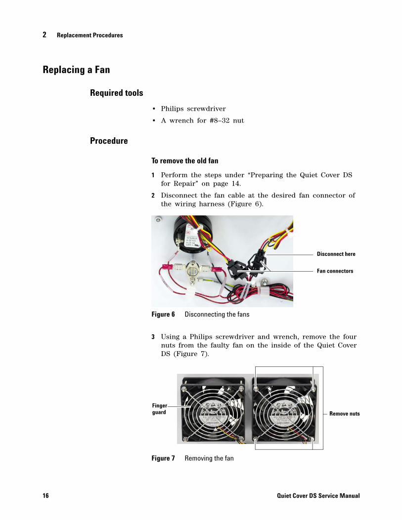
1 Perform the steps under “Preparing the Quiet Cover DS for Repair” on page 14.
2 Disconnect the fan cable at the desired fan connector of the wiring harness (Figure 6).
3 Using a Philips screwdriver and wrench, remove the four nuts from the faulty fan on the inside of the Quiet Cover DS (Figure 7).
Figure 6 Disconnecting the fans
Figure 7 Removing the fan
Disconnect here
Fan connectors
Remove nutsFingerguard
Quiet Cover DS Service Manual
Replacement Procedures 2
Quiet Cover DS Service Manual
4 Remove the finger guards and fan. Save the finger guards.
To install the new fan
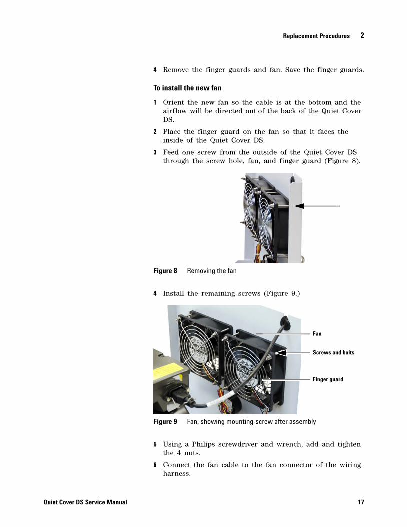
1 Orient the new fan so the cable is at the bottom and the airflow will be directed out of the back of the Quiet Cover DS.
2 Place the finger guard on the fan so that it faces the inside of the Quiet Cover DS.
3 Feed one screw from the outside of the Quiet Cover DS through the screw hole, fan, and finger guard (Figure 8).
4 Install the remaining screws (Figure 9.)
5 Using a Philips screwdriver and wrench, add and tighten the 4 nuts.
6 Connect the fan cable to the fan connector of the wiring harness.
Figure 8 Removing the fan
Figure 9 Fan, showing mounting-screw after assembly
Finger guard
Screws and bolts
Fan
17

2 Replacement Procedures
Replacing the Alarm
Required tools
18
• Philips screwdriver
Procedure
1 Perform the steps under “Preparing the Quiet Cover DS for Repair” on page 14.
2 Remove the wires (marked ALRM + and ALRM –) from the alarm (Figure 10).
3 From the outside of the Quiet Cover DS, unscrew the ring securing the alarm and remove the alarm (Figure 11).
4 Place a new alarm on the Quiet Cover DS, then completely screw the ring to secure the alarm to the chassis.
5 Reconnect the wires to the alarm, matching the ALRM + and ALRM – wires to the + and – terminals on the alarm.
Figure 10 Inside view of the back of the alarm
Figure 11 Outside view of the alarm
Alarm5188-1277
Connectors
Quiet Cover DS Service Manual
Replacement Procedures 2
Replacing the Thermostat
Required tools
Quiet Cover DS Service Manual
• Philips screwdriver
Procedure
1 Perform the steps under “Preparing the Quiet Cover DS for Repair” on page 14.
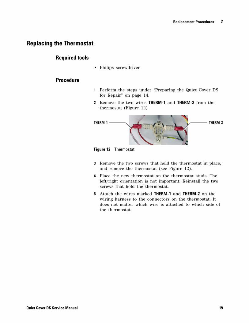
2 Remove the two wires THERM-1 and THERM-2 from the thermostat (Figure 12).
3 Remove the two screws that hold the thermostat in place, and remove the thermostat (see Figure 12).
4 Place the new thermostat on the thermostat studs. The left/right orientation is not important. Reinstall the two screws that hold the thermostat.
5 Attach the wires marked THERM-1 and THERM-2 on the wiring harness to the connectors on the thermostat. It does not matter which wire is attached to which side of the thermostat.
Figure 12 Thermostat
THERM-1 THERM-2
19

2 Replacement Procedures
Replacing the On/Off Switch
Required tools
20
None
Procedure
1 Perform the steps under “Preparing the Quiet Cover DS for Repair” on page 14.
2 Inside the cabinet remove the two wires SW-1 and SW-2 from the on/off switch (Figure 13).
3 Squeeze the latches on the back of the switch and push it out through the front of the Quiet Cover DS.
4 Toggle the new switch so the red does not show.
5 With the raised end of the switch at the top, push the new switch in place. (The two wiring connectors will be towards the bottom of the switch, see Figure 13.)
6 Connect the SW-2 wire from the wiring harness to the top connector of the switch and the SW-1 wire to the bottom connector.
Figure 13 Wires to remove from the on/off switch
Remove wires
Quiet Cover DS Service Manual

Replacement Procedures 2
Replacing an LED
Required tools
Quiet Cover DS Service Manual
• A wrench for #6–32 nut
Procedure
1 Perform the steps under “Preparing the Quiet Cover DS for Repair” on page 14.
2 Remove the + and – wires (marked GLED+/– or RLED+/–) from the faulty LED (Figure 14).
3 Remove the nut that secures the metal LED holder.
4 Remove the faulty LED and replace it with a new one.
5 Replace the metal LED holder, making sure that both LEDs and the nylon holder for the ferrite are in place.
6 While holding the metal LED holder, secure it with the nut. Check once again that the ferrite in the wire holder is still attached to the back of the LED holder.
7 Reattach wires to the replacement LED. Hold the LED firmly so that the connectors do not bend.
• If replacing the red LED, connect the RLED+ wire to the red + connector tab and the RLED– wire to the red – connector tab.
• If replacing the green LED, connect the GLED+ wire to the green + connector tab and the GLED– wire to the green – connector tab.
Figure 14 LED connectors
Remove wires
Metal LED holder
Screw
Green LED
Red LED
FerriteFerrite
21
2 Replacement Procedures
Replacing the Wiring Harness
Required tools
22
• Pliers with wire cutter
• Philips screwdriver
Procedure
To remove the old wiring harness
1 Perform the steps under “Preparing the Quiet Cover DS for Repair” on page 14.
2 Disconnect the wiring harness connections for the alarm, fans, thermostat, on/off switch, and LEDs. Loosen and remove the nut retaining the grounding wire. (This is located below the thermostat.)
3 Remove the ferrite from the nylon holder.
4 Cut the red 24+ and the green 24– wires from the power connector on the inside back of the Quiet Cover DS. Remove the old wiring harness, slipping the wires out of each of the nylon holders.
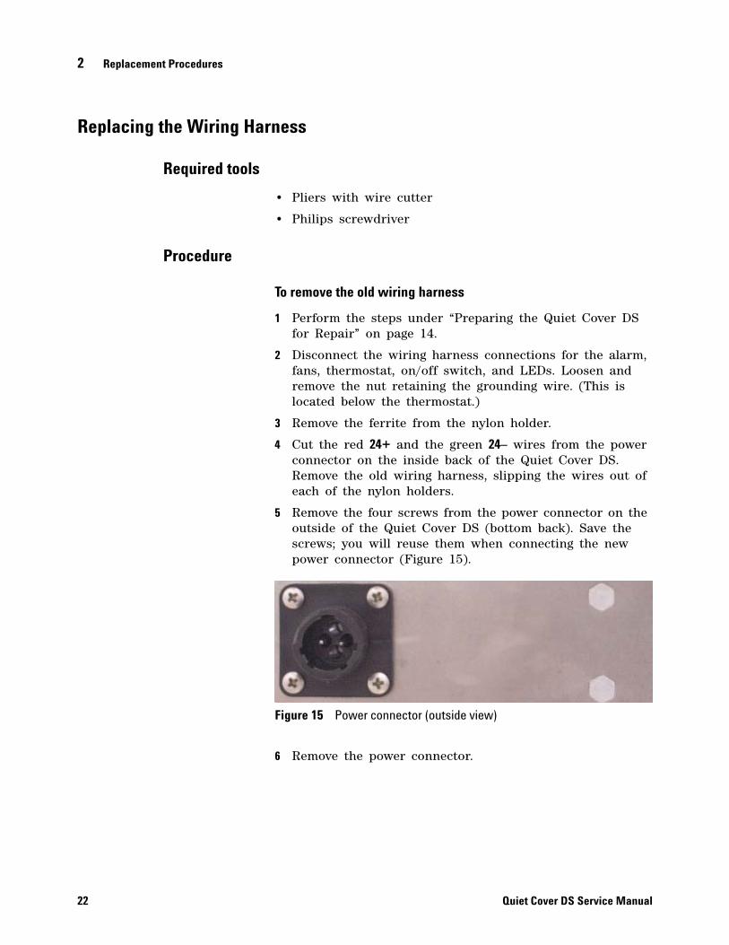
5 Remove the four screws from the power connector on the outside of the Quiet Cover DS (bottom back). Save the screws; you will reuse them when connecting the new power connector (Figure 15).
6 Remove the power connector.
Figure 15 Power connector (outside view)
Quiet Cover DS Service Manual

Replacement Procedures 2
Quiet Cover DS Service Manual
To connect the new wiring harness
1 Install the new power connector into the back of the Quiet Cover DS using the screws from before. Pinhole 1 should be on the top inside and pinhole 4 should be on the bottom. (Pinholes 2 and 3 are horizontal from each other and used for the electrical connection in step 4.)
2 Place the new wiring harness along the side rail of the Quiet Cover DS, with the ferrite end at the front of the box.
3 Slide the wires into the nylon wire holders along the inside of the rail.
4 Connect all the wiring as indicated below:
• Power connector. Insert the red 24+ wire into pin 2 and the black 24– wire into pin 3 of the power connector on the inside of the Quiet Cover DS (Figure 16).
• Thermostat. On the inside back of the Quiet Cover DS, attach the THERM-1 and the THERM-2 wires to the two thermostat connector tabs.
• Alarm. Attach the ALRM + wire to the + side of the alarm connector tab and the ALRM – wire to the – side of the alarm.
• Fans. Connect both fans.
• Ferrite. Slide the wires of the ferrite into the wire holder attached to the center of the LED holder. Then, slide the ferrite into the holder so it is held firmly in place next to the LED holder.
• LEDs. Connect the + and – wires (marked GLED +/– and RLED +/–) to the green and red LEDs, respectively.
• On/off switch. Connect the SW-2 wire to the top switch connector tab and the SW-1 wire to the bottom connector tab.
5 Verify that the oil tray does not pinch any of the wires when sliding it in and out of the Quiet Cover DS.
Figure 16 Connecting the power connector on the Quiet Cover DS
23
24
2 Replacement Procedures
Quiet Cover DS Service Manual
Agilent G6012A Quiet Cover DSService Manual
3Replaceable Parts
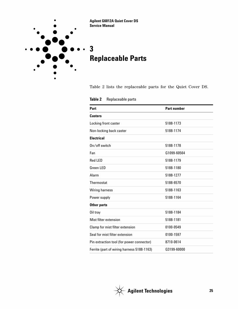
Table 2 lists the replaceable parts for the Quiet Cover DS.
Table 2 Replaceable parts
Part Part number
Casters
Locking front caster 5188-1173
Non-locking back caster 5188-1174
Electrical
On/off switch 5188-1178
Fan G1099-60564
Red LED 5188-1179
Green LED 5188-1180
Alarm 5188-1277
Thermostat 5188-6570
Wiring harness 5188-1163
Power supply 5188-1164
Other parts
Oil tray 5188-1184
Mist filter extension 5188-1181
Clamp for mist filter extension 0100-0549
Seal for mist filter extension 0100-1597
Pin extraction tool (for power connector) 8710-0614
Ferrite (part of wiring harness 5188-1163) G3199-60000
25Agilent Technologies

Agilent Technologies
© Agilent Technologies, Inc. 2012
G6012-90020*G6012-90020*