Embed Size (px)
Citation preview
Agilent U1251B and U1252B Handheld Digital Multimeter
User’s and Service Guide
Agilent Technologies
2 Agilent U1251B/U1252B User’s and Service Guide
Notices© Agilent Technologies, Inc. 2009
No part of this manual may be reproduced in any form or by any means (including elec-tronic storage and retrieval or translation into a foreign language) without prior agree-ment and written consent from Agilent Technologies, Inc. as governed by United States and international copyright laws.
Manual Part NumberU1251-90036
EditionFirst Edition, December 01, 2009
Printed in Malaysia
Agilent Technologies, Inc.5301 Stevens Creek Blvd.Santa Clara, CA 95051 USA
Technology Licenses The hardware and/or software described in this document are furnished under a license and may be used or copied only in accor-dance with the terms of such license.
Restricted Rights Legend
U.S. Government Restricted Rights. Soft-ware and technical data rights granted to the federal government include only those rights customarily provided to end user cus-tomers. Agilent provides this customary commercial license in Software and techni-cal data pursuant to FAR 12.211 (Technical Data) and 12.212 (Computer Software) and, for the Department of Defense, DFARS 252.227-7015 (Technical Data - Commercial Items) and DFARS 227.7202-3 (Rights in Commercial Computer Software or Com-puter Software Documentation).
Warranty
The material contained in this docu-ment is provided “as is,” and is sub-ject to being changed, without notice, in future editions. Further, to the max-imum extent permitted by applicable law, Agilent disclaims all warranties, either express or implied, with regard to this manual and any information contained herein, including but not limited to the implied warranties of merchantability and fitness for a par-ticular purpose. Agilent shall not be liable for errors or for incidental or consequential damages in connec-tion with the furnishing, use, or per-formance of this document or of any information contained herein. Should Agilent and the user have a separate written agreement with warranty terms covering the material in this document that conflict with these terms, the warranty terms in the sep-arate agreement shall control.
Accessories Warranty Agilent offers warranty for product’s acces-sories for up to 3 months from the end-user acceptance date.
Standard Calibration Service (optional)Agilent offers an optional calibration service contract for a period of 3 years from end-user acceptance date.
Safety Notices
CAUTION
A CAUTION notice denotes a haz-ard. It calls attention to an operat-ing procedure, practice, or the like that, if not correctly performed or adhered to, could result in damage to the product or loss of important data. Do not proceed beyond a CAUTION notice until the indicated conditions are fully understood and met.
WARNING
A WARNING notice denotes a hazard. It calls attention to an operating procedure, practice, or the like that, if not correctly per-formed or adhered to, could result in personal injury or death. Do not proceed beyond a WARNING notice until the indicated condi-tions are fully understood and met.
Safety SymbolsThe following symbols on the instrument and in the documentation indicate precautions which must be taken to maintain safe operation of the instrument.
Direct current (DC) Off (supply)
Alternating current (AC) On (supply)
Both direct and alternating current Caution, risk of electric shock
Three-phase alternating currentCaution, risk of danger (refer to this manual for specific Warning or Caution information)
Earth (ground) terminal Caution, hot surface
Protective conductor terminal Out position of a bi-stable push control
Frame or chassis terminal In position of a bi-stable push control
Equipotentiality Category III 1000 V overvoltage protection
Equipment protected throughout bydouble insulation or reinforcedinsulation
Category IV 600 V overvoltage protection
CAT III1000 V
CAT IV600 V
Agilent U1251B/U1252B User’s and Service Guide III
Safety InformationThis meter is safety-certified in compliance with EN/IEC 61010-1:2001, UL 61010-1 Second Edition and CAN/CSA 22.2 61010-1 Second Edition, CAT III 1000 V/ CAT IV 600 V Overvoltage Protection, Pollution Degree II. Use with standard or compatible test probes.
General Safety InformationThe following general safety precautions must be observed during all phases of operation, service, and repair of this instrument. Failure to comply with these precautions or with specific warnings elsewhere in this manual violates safety standards of design, manufacture, and intended use of the instrument. Agilent Technologies assumes no liability for the customer’s failure to comply with these requirements.
IV Agilent U1251B/U1252B User’s and Service Guide
WARNING • When working above 70V DC, 33 V AC RMS or 46.7 V peak, exercise caution – such range pose a shock hazard.
• Do not measure more than the rated voltage (as marked on the meter) between terminals, or between terminal and earth ground.
• Double-check the meter’s operation by measuring a known voltage.• For current measurement, turn off circuit power before connecting the meter to the
circuit. Always place the meter in series with the circuit.• When connecting probes, always connect the common test probe first. When
disconnecting probes, always disconnect the live test probe first.• Detach test probes from the meter before you open the battery cover.• Do not use the meter with the battery cover or part of the cover removed or loose.
• Replace the battery as soon as the low battery indicator flashes on screen. This is to avoid false readings, which may lead to possible electric shock or personal injury.
• Do not operate the product in an explosive atmosphere or in the presence of flammable gases or fumes.
• Inspect the case for cracks or missing plastic. Pay extra attention to the insulation surrounding the connectors. Do not use the meter if it is damaged.
• Inspect the test probes for damaged insulation or exposed metal, and check for continuity. Do not use the test probe if it is damaged.
• Do not use any other AC charger adaptor apart from the one certified by Agilent with this product.
• Do not use repaired fuses or short-circuited fuse-holders. For continued protection against fire, replace the line fuses only with fuses of the same voltage and current rating and recommended type.
• Do not service or perform adjustments alone. Under certain condition, hazardous voltages may exist, even with the equipment switched off. To avoid dangerous electric shock, service personnel must not attempt internal service or adjustment unless another person, capable of rendering resuscitation or first aid, is present.
• Do not substitute parts or modify equipment to avoid the danger of introducing additional hazards. Return the product to Agilent Technologies Sales and Service Office for service and repair to ensure the safety features are maintained
• Do not operate damaged equipment as the safety protection features built into this product may have been impaired, either through physical damage, excessive moisture, or any other reason. Remove power and do not use the product until safe operation can be verified by service-trained personnel. If necessary, return the product to Agilent Technologies Sales and Service Office for service and repair to ensure the safety features are maintained.
Agilent U1251B/U1252B User’s and Service Guide V
CAUTION • Turn off circuit power and discharge all high-voltage capacitors in the circuit before you perform resistance, continuity, diodes, or capacitance tests.
• Use the correct terminals, function, and range for your measurements.• Never measure voltage when current measurement is selected.• Use only recommended rechargeable battery. Ensure proper insertion of battery in the
meter, and follow the correct polarity.• Disconnect test leads from all the terminals during battery charging.
VI Agilent U1251B/U1252B User’s and Service Guide
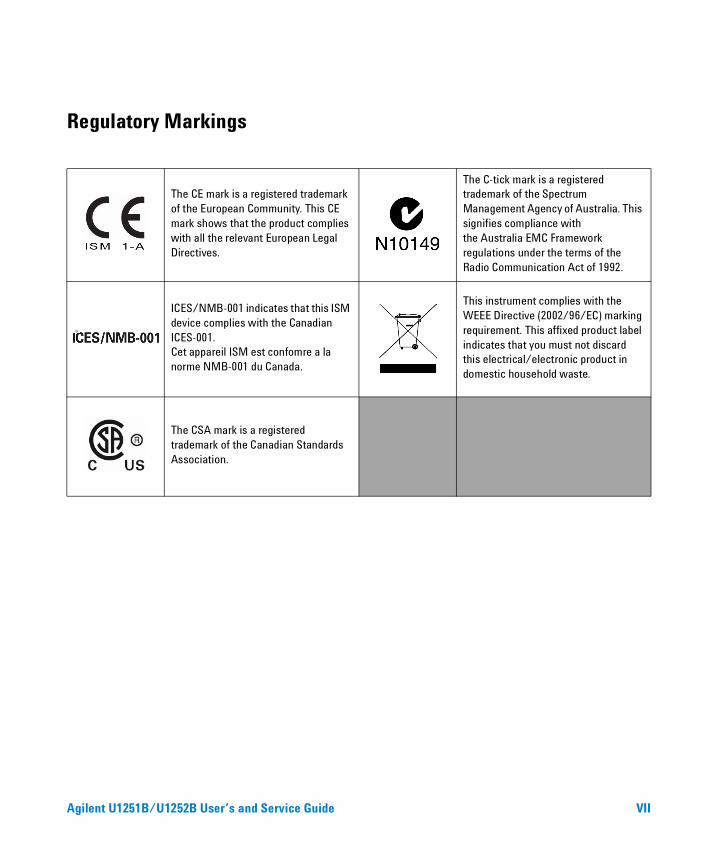
Regulatory Markings
The CE mark is a registered trademarkof the European Community. This CEmark shows that the product complieswith all the relevant European LegalDirectives.
The C-tick mark is a registered trademark of the Spectrum Management Agency of Australia. This signifies compliance withthe Australia EMC Frameworkregulations under the terms of the Radio Communication Act of 1992.
ICES/NMB-001 indicates that this ISM device complies with the Canadian ICES-001.Cet appareil ISM est confomre a la norme NMB-001 du Canada.
This instrument complies with the WEEE Directive (2002/96/EC) marking requirement. This affixed product label indicates that you must not discard this electrical/electronic product in domestic household waste.
The CSA mark is a registered trademark of the Canadian Standards Association.
Agilent U1251B/U1252B User’s and Service Guide VII
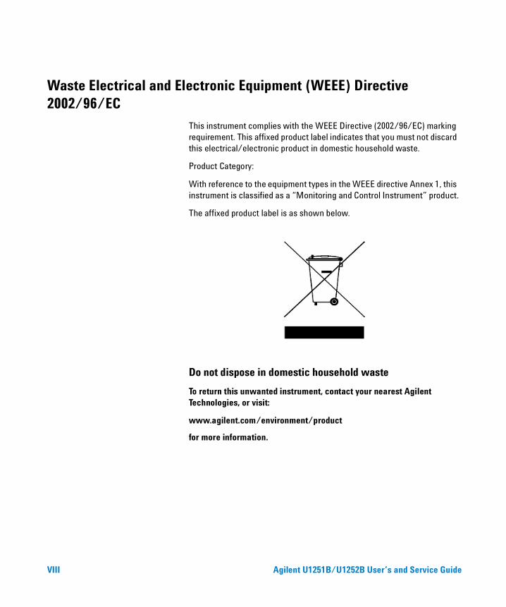
Waste Electrical and Electronic Equipment (WEEE) Directive 2002/96/EC
This instrument complies with the WEEE Directive (2002/96/EC) marking requirement. This affixed product label indicates that you must not discard this electrical/electronic product in domestic household waste.
Product Category:
With reference to the equipment types in the WEEE directive Annex 1, this instrument is classified as a “Monitoring and Control Instrument” product.
The affixed product label is as shown below.
Do not dispose in domestic household waste
To return this unwanted instrument, contact your nearest Agilent Technologies, or visit:
www.agilent.com/environment/product
for more information.
VIII Agilent U1251B/U1252B User’s and Service Guide
Declaration of Conformity (DoC)
The Declaration of Conformity (DoC) for this instrument is available on the Web site. You can search the DoC by its product model or description.
http://regulations.corporate.agilent.com/DoC/search.htm
NOTE If you are unable to search for the respective DoC, please contact your local Agilent representative.
Agilent U1251B/U1252B User’s and Service Guide IX

X Agilent U1251B/U1252B User’s and Service Guide
Contents
1 Getting Started Tutorial 1
Introducing the Agilent U1251B and U1252B Handheld Digital Multimeter 2
Adjusting the Tilt-Stand 3
The Front Panel at a Glance 5
The Rotary Switch at a Glance 6
The Keypad at a Glance 7
The Display at a Glance 9
Selection of Display by Hz Button 13
Selection of Display by Dual Button 15
Selection of Display by Shift Button 18
The Terminals at a Glance 20
The Rear Panel at a Glance 21
2 Making Measurements 23
Measuring Voltage 24Measuring Current 27Measuring DC voltage 26
Measuring Current 27µA & mA Measurement 27% Scale of 4–20 mA 28A measurement 29
Frequency Counter 30Measuring Resistance, Conductance and Testing Continuity 32
Testing Diodes 36
Measuring Capacitance 39Measuring Temperature 40
Alerts and Warning During Measurement 43Overload Alert 43Input Warning 43Charge Terminal Alert 44
Agilent U1251B/U1252B User’s and Service Guide XI
Contents
3 Features and Functions 45
Dynamic Recording 46
Data Hold (Trigger Hold) 48
Refresh Hold 49Null (Relative) 51
Decibel Display 53
1 ms Peak Hold 55
Data Logging 57Manual Logging 57Interval Logging 59Reviewing Logged Data 61
Square Wave Output (for U1252B) 63
Remote Communication 67
4 Changing The Default Setting 69
Selecting Setup Mode 70Setting Data Logging Mode 74Setting Thermocouple Types (for U1252B) 75Setting Reference Impedance for dBm Measurement 76Setting Minimum Frequency Measurement 77Setting Temperature Unit 78Setting Auto Power Saving Mode 80Setting % Scale Readout 82Setting Beep Frequency 83Setting Backlit Timer 84Setting Baud Rate 85Setting Parity Check 86Setting Data Bit 87Setting Echo Mode 88Setting Print Mode 89Returning to Default Factory Settings 90Setting the Battery Voltage 91Setting the DC Filter 92
5 Maintenance 93
Introduction 94General Maintenance 94Replacing the Battery 95Charging the Battery 97
XII Agilent U1251B/U1252B User’s and Service Guide
Contents
Replacing the Fuse 103Troubleshooting 105
6 Performance Tests and Calibration 107
Calibration Overview 108Closed-case Electronic Calibration 108Agilent Technologies Calibration Services 108Calibration Interval 108Adjustment is Recommended 109
Recommended Test Equipment 110Basic Operating Test 111Backlit Test 111Testing the Display 111Current Terminal Test 112
Charge Terminal Alert Test 113Test Considerations 114
Input Connections 115
Performance Verification Tests 116
Calibration Security 124
Unsecuring the Instrument for Calibration 125Calibration Process 128Using the Front Panel for Adjustments 129
Adjustments Consideration 130Valid Adjustment Input Values 131Adjustment Procedure 132Finishing the Adjustment 139To Read the Calibration Count 139Calibration Errors 140
7 Specifications 141
DC Specifications 142
U1251B AC Specifications 144
U1252B AC Specifications 145
U1252B AC+DC Specifications 146
Temperature and Capacitance Specifications 147
U1251B & U1252B Frequency Specifications 148
Agilent U1251B/U1252B User’s and Service Guide XIII
Contents
Operating Specifications 152
General Specifications 154
XIV Agilent U1251B/U1252B User’s and Service Guide
Agilent U1251B and U1252B Handheld Digital MultimeterUser’s and Service Guide
1Getting Started Tutorial
Introducing the Agilent U1251B and U1252B Handheld Digital Multimeter 2
Adjusting the Tilt-Stand 3
The Front Panel at a Glance 5
The Rotary Switch at a Glance 6
The Keypad at a Glance 7
The Display at a Glance 9
Selection of Display by Hz Button 13
Selection of Display by Dual Button 15
Selection of Display by Shift Button 18
The Terminals at a Glance 20
The Rear Panel at a Glance 21
This chapter contains a brief description of the front panel of the Agilent U1251B and U1252B Handheld Digital Multimeter.
1Agilent Technologies
1 Getting Started Tutorial
Introducing the Agilent U1251B and U1252B Handheld Digital Multimeter
The handheld digital multimeter’s key features are:
• DC, AC and AC + DC (only U1252B) voltage and current measurements.
• True- RMS measurement for both AC voltage and current
• Rechargeable Ni- MH battery with built- in charging capability (only for U1252B)
• Ambient temperature on second display
• Battery capacity indicator
• Bright orange LED backlight
• Resistance measurement up to 50 MΩ (for U1251B) and 500 MΩ (for U1252B)
• Conductance measurement from 0.01 nS (100 GΩ) ~ 50 nS
• Capacitance measurement up to 100 mF
• Frequency counter up to 20 MHz (only U1252B)
• The % scale readout for 4- 20 mA or 0-20 mA measurement
• dBm with selectable reference impedance
• 1 ms Peak Hold to catch inrush voltage and current easily
• Temperature test with selectable 0 °C compensation (without ambient temperature compensation).
• K- type (for U1251B) and J/K- types temperature measurement (for U1252B)
• Frequency, duty cycle and pulse width measurements
• Dynamic Recording for min, max and average readings
• Data Hold with manual or auto trigger and Null mode
• Diode and audible continuity tests
• Square wave generator with selectable frequency, pulse width and duty cycle (only U1252B)
• Agilent GUI Application Software (IR- USB cable sold separately)
• Closed case calibration
2 Agilent U1251B/U1252B User’s and Service Guide
Getting Started Tutorial 1
• 50,000 count precision true RMS digital multimeter, designed to meet IEC61326- 1:2005 / EN61326- 1:2006 Category III 1000 V/ CAT IV 600 V Overvoltage Protection, Pollution Degree II standards
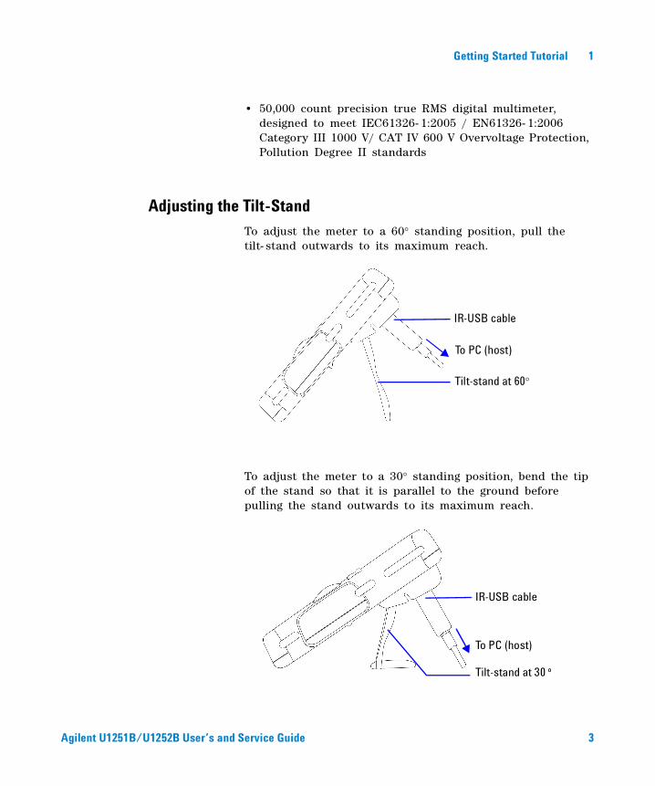
Adjusting the Tilt-StandTo adjust the meter to a 60° standing position, pull the tilt- stand outwards to its maximum reach.
To adjust the meter to a 30° standing position, bend the tip of the stand so that it is parallel to the ground before pulling the stand outwards to its maximum reach.
To PC (host)
Tilt-stand at 30 º
IR-USB cable
To PC (host)
Tilt-stand at 60°
IR-USB cable
Agilent U1251B/U1252B User’s and Service Guide 3
Getting Started Tutorial 1
Agilent U1251B/U1252B User’s and Service Guide 4
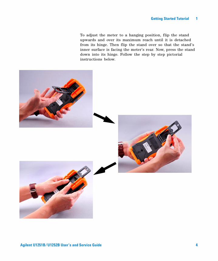
To adjust the meter to a hanging position, flip the stand upwards and over its maximum reach until it is detached from its hinge. Then flip the stand over so that the stand’s inner surface is facing the meter’s rear. Now, press the stand down into its hinge. Follow the step by step pictorial instructions below.
Getting Started Tutorial 1
Agilent U1251B/U1252B User’s and Service Guide 5
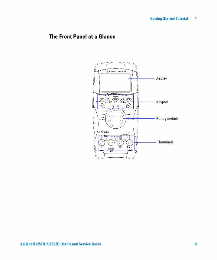
The Front Panel at a Glance
Display
Keypad
Rotary switch
Display
Terminals
1 Getting Started Tutorial
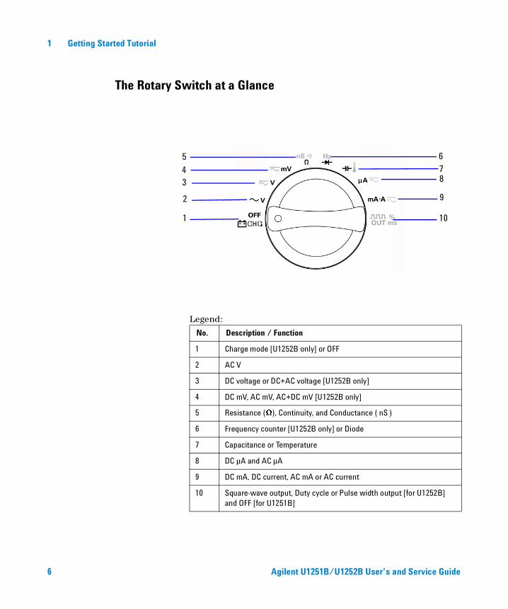
The Rotary Switch at a Glance
Legend:
No. Description / Function
1 Charge mode [U1252B only] or OFF
2 AC V
3 DC voltage or DC+AC voltage [U1252B only]
4 DC mV, AC mV, AC+DC mV [U1252B only]
5 Resistance (Ω), Continuity, and Conductance ( nS )
6 Frequency counter [U1252B only] or Diode
7 Capacitance or Temperature
8 DC µA and AC µA
9 DC mA, DC current, AC mA or AC current
10 Square-wave output, Duty cycle or Pulse width output [for U1252B] and OFF [for U1251B]
2
1
34 75 6
8
9
10
6 Agilent U1251B/U1252B User’s and Service Guide
Getting Started Tutorial 1
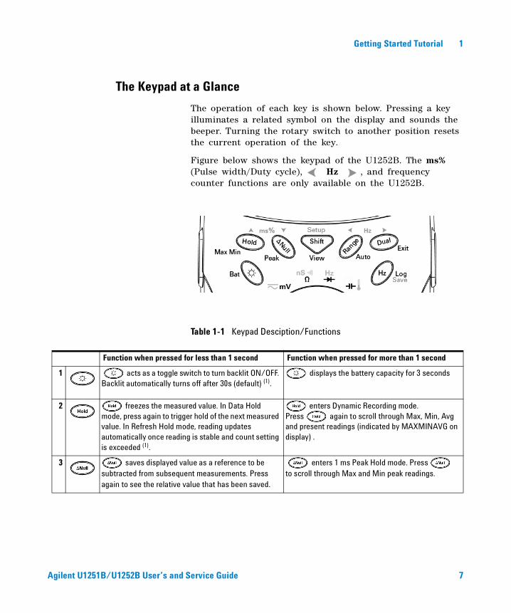
The Keypad at a Glance
The operation of each key is shown below. Pressing a key illuminates a related symbol on the display and sounds the beeper. Turning the rotary switch to another position resets the current operation of the key.
Figure below shows the keypad of the U1252B. The ms% (Pulse width/Duty cycle), Hz , and frequency counter functions are only available on the U1252B.
Table 1-1 Keypad Desciption/Functions
Function when pressed for less than 1 second Function when pressed for more than 1 second
1 acts as a toggle switch to turn backlit ON/OFF. Backlit automatically turns off after 30s (default) (1).
displays the battery capacity for 3 seconds
2 freezes the measured value. In Data Hold mode, press again to trigger hold of the next measured value. In Refresh Hold mode, reading updates automatically once reading is stable and count setting is exceeded (1).
enters Dynamic Recording mode. Press again to scroll through Max, Min, Avg and present readings (indicated by MAXMINAVG on display) .
3 saves displayed value as a reference to be subtracted from subsequent measurements. Press again to see the relative value that has been saved.
enters 1 ms Peak Hold mode. Press to scroll through Max and Min peak readings.
Agilent U1251B/U1252B User’s and Service Guide 7
1 Getting Started Tutorial
Function when pressed for less than 1 second Function when pressed for more than 1 second
4 scrolls through the measuring function(s) at a particular rotary switch position.
enters Log Review mode. Press to switch to manual or interval logging data. Press or to view first or last logged data respectively. Press or to scroll up or down logged data.Press for more than 1 second to exit mode.
5 scrolls through available measuring ranges (except when rotary switch is set at or at Hz [for U1252B] position) (2).
sets to Auto Range mode.
6 scrolls through available dual-combination displays (except when rotary switch is set at or [for U1252B] position, or when meter is in 1 ms peak hold or dynamic recording mode) (3).
exits Hold, Null, Dynamic Recording, 1 ms Peak Hold and dual display modes.
7 enters Frequency Test mode for current or voltage measurements. Press to scroll through frequency (Hz), duty cycle (%) and pulse width (ms) functions. In duty cycle (%) and pulse width (ms) tests, press to switch to positive or negative pulse.
enters logging mode. In manual data logging, press to log data manually into memory. In automatic data logging, data logs automatically (1). Press for more than 1 second to exit auto data logging mode.
NOTE 1. See Table 4-1, “Available setting options in Setup mode,” on page 71 for details of available options.
2. When rotary switch is at , press to switch to ºC or ºF display. When
rotary swtich is at Hz, press to switch to division of signal frequency by 1 or 100.
3. When rotary switch is at , ETC is ON by default. You may press to disable ETC (Environment Temperature Compensation), will appear on display.
For pulse and duty cycle measurement, press to switch trigger slope to positive or negative. When meter is in peak or dynamic-recording mode, press
to restart 1 ms peak hold or dynamic recording mode.
8 Agilent U1251B/U1252B User’s and Service Guide
Getting Started Tutorial 1
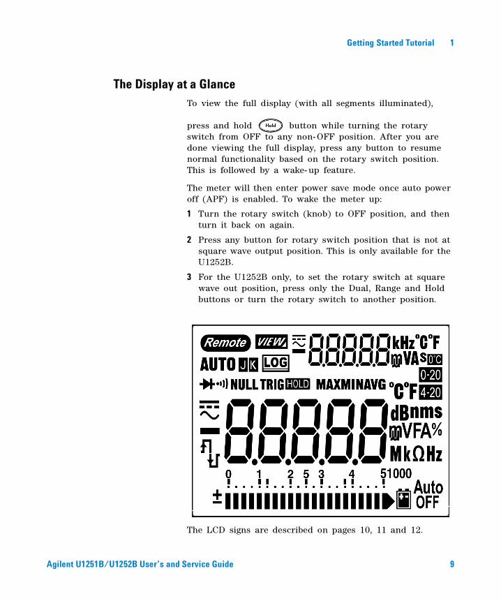
The Display at a GlanceTo view the full display (with all segments illuminated),
press and hold button while turning the rotary switch from OFF to any non- OFF position. After you are done viewing the full display, press any button to resume normal functionality based on the rotary switch position. This is followed by a wake- up feature.
The meter will then enter power save mode once auto power off (APF) is enabled. To wake the meter up:
1 Turn the rotary switch (knob) to OFF position, and then turn it back on again.
2 Press any button for rotary switch position that is not at square wave output position. This is only available for the U1252B.
3 For the U1252B only, to set the rotary switch at square wave out position, press only the Dual, Range and Hold buttons or turn the rotary switch to another position.
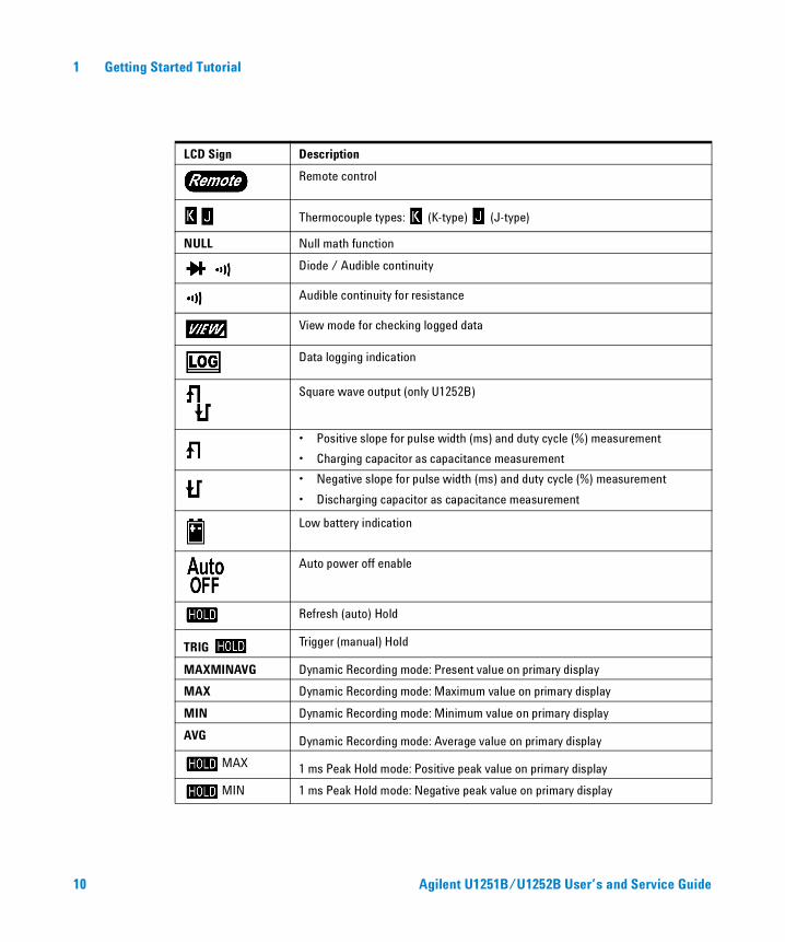
The LCD signs are described on pages 10, 11 and 12.
Agilent U1251B/U1252B User’s and Service Guide 9
1 Getting Started Tutorial
LCD Sign Description
Remote control
Thermocouple types: (K-type) (J-type)
NULL Null math function
Diode / Audible continuity
Audible continuity for resistance
View mode for checking logged data
Data logging indication
Square wave output (only U1252B)
• Positive slope for pulse width (ms) and duty cycle (%) measurement
• Charging capacitor as capacitance measurement
• Negative slope for pulse width (ms) and duty cycle (%) measurement
• Discharging capacitor as capacitance measurement
Low battery indication
Auto power off enable
Refresh (auto) Hold
TRIG Trigger (manual) Hold
MAXMINAVG Dynamic Recording mode: Present value on primary display
MAX Dynamic Recording mode: Maximum value on primary display
MIN Dynamic Recording mode: Minimum value on primary display
AVG Dynamic Recording mode: Average value on primary display
MAX 1 ms Peak Hold mode: Positive peak value on primary display
MIN 1 ms Peak Hold mode: Negative peak value on primary display
10 Agilent U1251B/U1252B User’s and Service Guide
Getting Started Tutorial 1
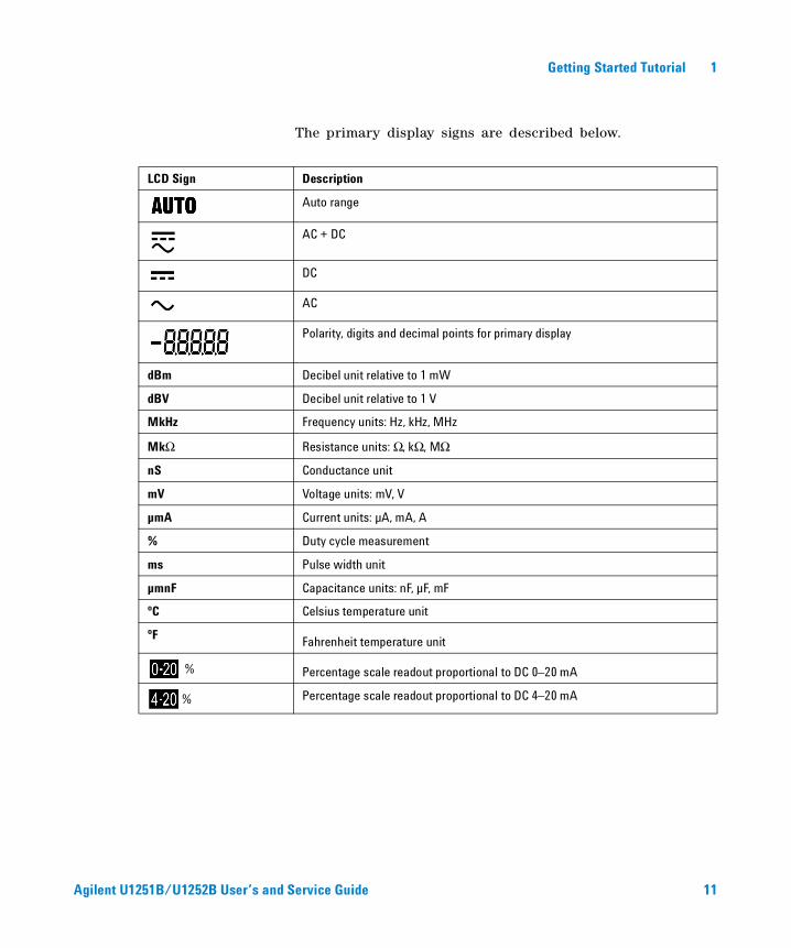
The primary display signs are described below.
LCD Sign Description
Auto range
AC + DC
DC
AC
Polarity, digits and decimal points for primary display
dBm Decibel unit relative to 1 mW
dBV Decibel unit relative to 1 V
MkHz Frequency units: Hz, kHz, MHz
MkΩ Resistance units: Ω, kΩ, MΩ
nS Conductance unit
mV Voltage units: mV, V
µmA Current units: µA, mA, A
% Duty cycle measurement
ms Pulse width unit
µmnF Capacitance units: nF, µF, mF
ºC Celsius temperature unit
ºF Fahrenheit temperature unit
% Percentage scale readout proportional to DC 0–20 mA
% Percentage scale readout proportional to DC 4–20 mA
Agilent U1251B/U1252B User’s and Service Guide 11
1 Getting Started Tutorial
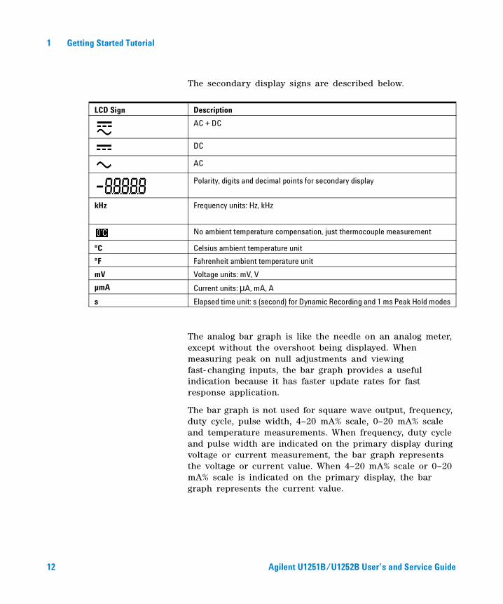
The secondary display signs are described below.
The analog bar graph is like the needle on an analog meter, except without the overshoot being displayed. When measuring peak on null adjustments and viewing fast- changing inputs, the bar graph provides a useful indication because it has faster update rates for fast response application.
The bar graph is not used for square wave output, frequency, duty cycle, pulse width, 4–20 mA% scale, 0–20 mA% scale and temperature measurements. When frequency, duty cycle and pulse width are indicated on the primary display during voltage or current measurement, the bar graph represents the voltage or current value. When 4–20 mA% scale or 0–20 mA% scale is indicated on the primary display, the bar graph represents the current value.
LCD Sign Description
AC + DC
DC
AC
Polarity, digits and decimal points for secondary display
kHz Frequency units: Hz, kHz
No ambient temperature compensation, just thermocouple measurement
ºC Celsius ambient temperature unit
ºF Fahrenheit ambient temperature unit
mV Voltage units: mV, V
µmA Current units: µA, mA, A
s Elapsed time unit: s (second) for Dynamic Recording and 1 ms Peak Hold modes
12 Agilent U1251B/U1252B User’s and Service Guide
Getting Started Tutorial 1
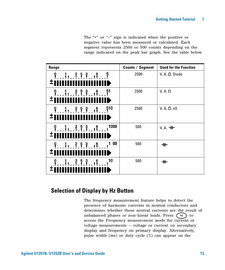
The “+” or “–” sign is indicated when the positive or negative value has been measured or calculated. Each segment represents 2500 or 500 counts depending on the range indicated on the peak bar graph. See the table below.
Selection of Display by Hz Button
The frequency measurement feature helps to detect the presence of harmonic currents in neutral conductors and determines whether these neutral currents are the result of unbalanced phases or non- linear loads. Press to access the Frequency measurement mode for current or voltage measurements — voltage or current on secondary display and frequency on primary display. Alternatively, pulse width (ms) or duty cycle (%) can appear on the
Range Counts / Segment Used for the Function
2500 V, A, Ω, Diode
2500 V, A, Ω
2500 V, A, Ω, nS
500 V, A,
500
500
Agilent U1251B/U1252B User’s and Service Guide 13
1 Getting Started Tutorial
primary display by pressing again. This enbles the simultaneous monitoring of real- time voltage and current with frequency, duty cycle or pulse width. Voltage or current resumes on primary display after you press and hold for more than 1 second.
Rotary switch position (Function) Primary display Secondary display
for U1252B
(DC voltage)
Frequency (Hz) AC V
Pulse width (ms)
Duty cycle (%) for U1251B
for U1252B
(DC voltage)
Frequency (Hz) DC V
Pulse width (ms)
Duty cycle (%)
for U1252B
(AC + DC voltage)
Frequency (Hz) AC + DC V
Pulse width (ms)
Duty cycle (%)
(AC voltage)
Frequency (Hz) AC mV
Pulse width (ms)
Duty cycle (%)
(DC voltage)
Frequency (Hz) DC mV
Pulse width (ms)
Duty cycle (%)
(AC + DC voltage)
Frequency (Hz) AC + DC mV
Pulse width (ms)
Duty cycle (%)
(AC Current)
Frequency (Hz) AC µA
Pulse width (ms)
Duty cycle (%)
(DC current)
Frequency (Hz) DC µA
Pulse width (ms)
Duty cycle (%)
[for U1252B]
14 Agilent U1251B/U1252B User’s and Service Guide
Getting Started Tutorial 1
Selection of Display by Dual Button
Press to select different combinations of dual display.
Normal single display resumes after you press and hold
for more than 1 second. See table below.
(AC + DC current)
[for U1252B]
Frequency (Hz) AC + DC µA
Pulse width (ms)
Duty cycle (%)
(AC current)
Frequency (Hz) AC mA or A
Pulse width (ms)
Duty cycle (%)
(DC current)
Frequency (Hz) DC mA or A
Pulse width (ms)
Duty cycle (%)
(AC + DC current)
[for U1252B]
Frequency (Hz) AC + DC mA
Pulse width (ms)
Duty cycle (%)
Hz (Frequency counter) - press
to select frequency
division by 1 [for U1252B]
Frequency (Hz) - 1 -
Pulse width (ms)
Duty cycle (%)
Hz (Frequency counter) - press
to select frequency
division by 100 [for U1252B]
Frequency (Hz) - 100 -
Agilent U1251B/U1252B User’s and Service Guide 15
1 Getting Started Tutorial
Rotary switch position
(Function)
Primary display Secondary display
AC V Hz (AC coupling)
(AC voltage) dBm or dBV (select
by pressing )
AC V
AC V Ambient temperature °C or °F
for U1252B
(AC voltage)
AC V Hz (AC coupling)
dBm or dBV (1) AC V
AC V DC V
AC V Ambient temperature °C or °F for U1251B/
for U1252B
(DC voltage)
DC V Hz (DC coupling)
dBm or dBV (1) DC V
DC V AC V [for U1252B]
DC V Ambient temperature °C or °Ffor U1252B
(AC + DC voltage)
AC + DC V Hz (AC coupling)
dBm or dBV (1) AC + DC V
AC + DC V AC V
AC + DC V DC V
AC + DC V Ambient temperature °C or °F
(AC voltage)
AC mV Hz (AC coupling)
dBm or dBV (1) AC mV
AC mV DC mV
AC mV Ambient temperature °C or °F
(DC voltage)
DC mV Hz (DC coupling)
dBm or dBV (1) DC mV
DC mV AC mV
DC mV Ambient temperature °C or °F
NOTE [1] Reading of dBm or dBV depends on the last review on AC V. If the last review is dBV, the following display will also remain in dBV.
16 Agilent U1251B/U1252B User’s and Service Guide
Getting Started Tutorial 1
(AC + DC voltage)
[for U1252B]
AC + DC mV Hz (AC coupling)
dBm or dBV AC + DC mV
AC + DC mV AC mV
AC + DC mV DC mV
AC + DC mV Ambient temperature °C or °F
(DC current)
DC μA Hz (DC coupling)
DC μA AC μA
DC μA Ambient temperature °C or °F
AC μA Hz (AC coupling)
(AC current) AC μA DC μA
AC μA Ambient temperature °C or °F
AC + DC μA Hz (AC coupling)
(AC + DC current) AC + DC μA AC μA
AC + DC μA DC μA
AC + DC μA Ambient temperature °C or °F
DC mA Hz (DC coupling)
(DC current) DC mA AC mA
%(0–20 or 4–20) DC mA
DC mA Ambient temperature °C or °F
AC mA Hz (AC coupling)
(AC current) AC mA DC mA
AC mA Ambient temperature °C or °F
AC + DC mA Hz (AC coupling)
(AC + DC current)[for U1252B]
AC + DC mA AC mA
AC + DC mA DC mA
AC + DC mA Ambient temperature °C or °F
DC A Hz (DC coupling)
(DC current) DC A AC A
DC A Ambient temperature °C or °F
[for U1252B]
Agilent U1251B/U1252B User’s and Service Guide 17
1 Getting Started Tutorial
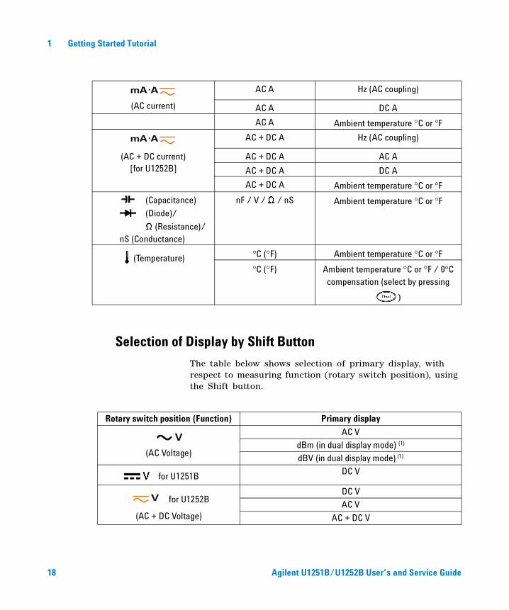
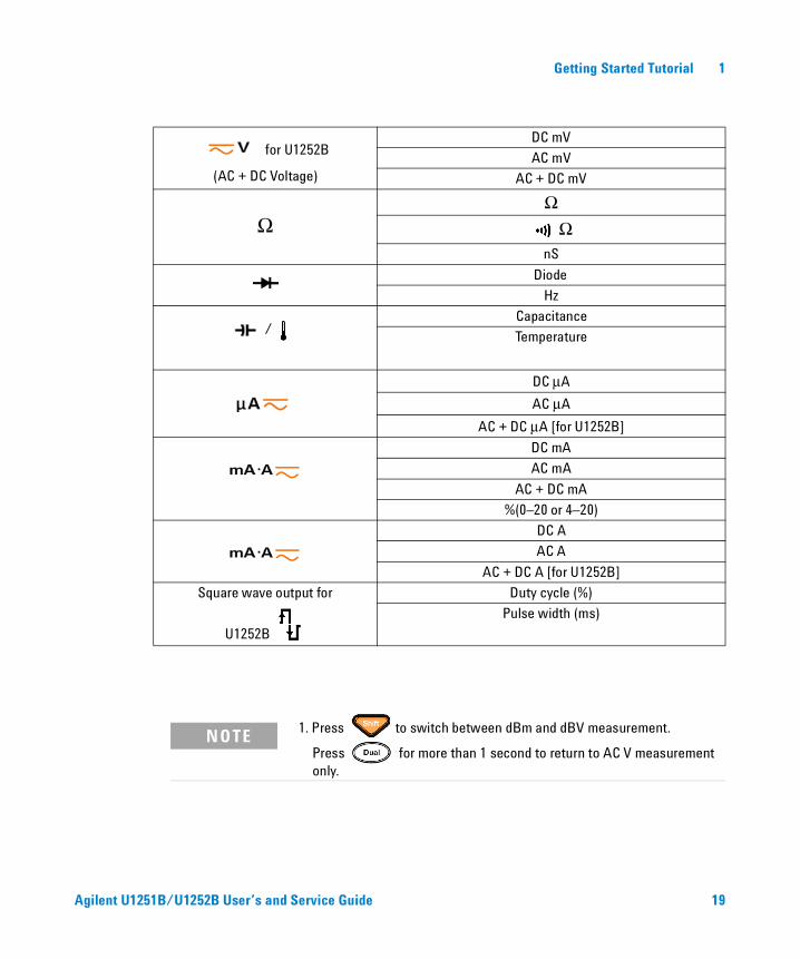
Selection of Display by Shift Button
The table below shows selection of primary display, with respect to measuring function (rotary switch position), using the Shift button.
AC A Hz (AC coupling)
(AC current) AC A DC A
AC A Ambient temperature °C or °F
AC + DC A Hz (AC coupling)
(AC + DC current) AC + DC A AC A[for U1252B] AC + DC A DC A
AC + DC A Ambient temperature °C or °F
(Capacitance)
(Diode)/
Ω (Resistance)/nS (Conductance)
nF / V / Ω / nS Ambient temperature °C or °F
(Temperature) °C (°F) Ambient temperature °C or °F
°C (°F) Ambient temperature °C or °F / 0°C compensation (select by pressing
)
Rotary switch position (Function) Primary display
(AC Voltage)
AC V
dBm (in dual display mode) (1)
dBV (in dual display mode) (1)
for U1251B DC V
for U1252B
(AC + DC Voltage)
DC V
AC V
AC + DC V
18 Agilent U1251B/U1252B User’s and Service Guide
Getting Started Tutorial 1
for U1252B
(AC + DC Voltage)
DC mV
AC mV
AC + DC mV
ΩΩ
ΩnS
Diode
Hz
/ Capacitance
Temperature
DC μA
AC μA
AC + DC μA [for U1252B]
DC mA
AC mA
AC + DC mA
%(0–20 or 4–20)
DC A
AC A
AC + DC A [for U1252B]
Square wave output for
U1252B
Duty cycle (%)
Pulse width (ms)
NOTE 1. Press to switch between dBm and dBV measurement.
Press for more than 1 second to return to AC V measurement only.
Agilent U1251B/U1252B User’s and Service Guide 19
1 Getting Started Tutorial
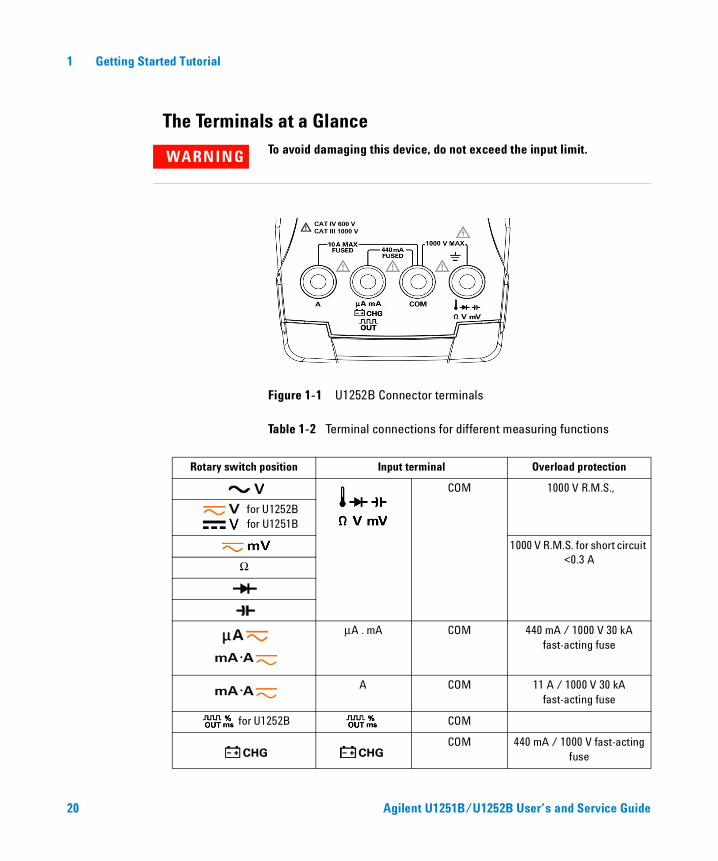
The Terminals at a Glance
Figure 1-1 U1252B Connector terminals
Table 1-2 Terminal connections for different measuring functions
WARNING To avoid damaging this device, do not exceed the input limit.
Rotary switch position Input terminal Overload protection
COM 1000 V R.M.S.,
for U1252B for U1251B
1000 V R.M.S. for short circuit <0.3 AΩ
μA . mA COM 440 mA / 1000 V 30 kA fast-acting fuse
A COM 11 A / 1000 V 30 kA fast-acting fuse
for U1252B COM
COM 440 mA / 1000 V fast-acting fuse
20 Agilent U1251B/U1252B User’s and Service Guide
Getting Started Tutorial 1
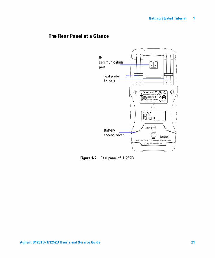
The Rear Panel at a Glance
Figure 1-2 Rear panel of U1252B
IR communication port
Test probe holders
Battery access cover
Agilent U1251B/U1252B User’s and Service Guide 21

1 Getting Started Tutorial
22 Agilent U1251B/U1252B User’s and Service Guide
Agilent U1251B and U1252B Handheld Digital MultimeterUser’s and Service Guide
2 Making Measurements
Measuring Voltage 24
Measuring AC voltage 24
Measuring DC voltage 26
Measuring Current 27
μA & mA Measurement 39
% Scale of 4–20 mA 28
A measurement 29
Frequency Counter 30
Measuring Resistance, Conductance and Testing Continuity 32
Testing Diodes 36
Measuring Temperature 40
Alerts and Warning During Measurement 43
Overload Alert 43
Input Warning 43
Charge Terminal Alert 44
This chapter contains detailed information on how measurements are taken using this handheld digital multimeter. It builds on information you have learned in the Quick Start Guide.
23Agilent Technologies
2 Making Measurements
Measuring Voltage
The meter offers true- RMS readings for AC measurements
that are accurate for sine waves, square waves, triangle
waves, staircase waves and other waveforms without any DC
offset.
For AC with DC offset, use AC + DC measurement on or rotary switch location. This applies only to U1252B.
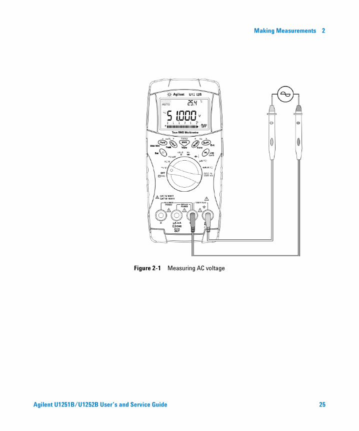
Measuring AC voltage
1 Set the rotary switch to , or .
2 Connect the red and black test leads to the input terminals V.mV and COM respectively.
3 Alternatively, press to display frequency on secondary display.
4 Probe the test points and read the display.
WARNING Ensure that the terminal connections are correct for that particular measurement before proceeding with the measurement. To avoid damaging the device, do not exceed the input limit.
24 Agilent U1251B/U1252B User’s and Service Guide
Making Measurements 2
Figure 2-1 Measuring AC voltage
Agilent U1251B/U1252B User’s and Service Guide 25
2 Making Measurements
Measuring DC voltage
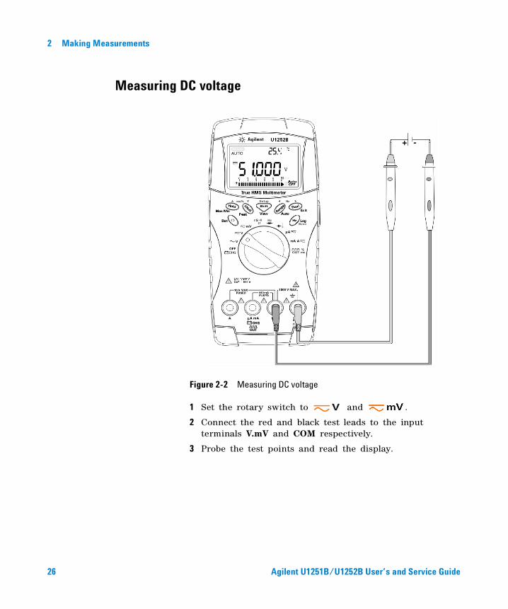
Figure 2-2 Measuring DC voltage
1 Set the rotary switch to and .
2 Connect the red and black test leads to the input terminals V.mV and COM respectively.
3 Probe the test points and read the display.
26 Agilent U1251B/U1252B User’s and Service Guide
Making Measurements 2
Measuring Current
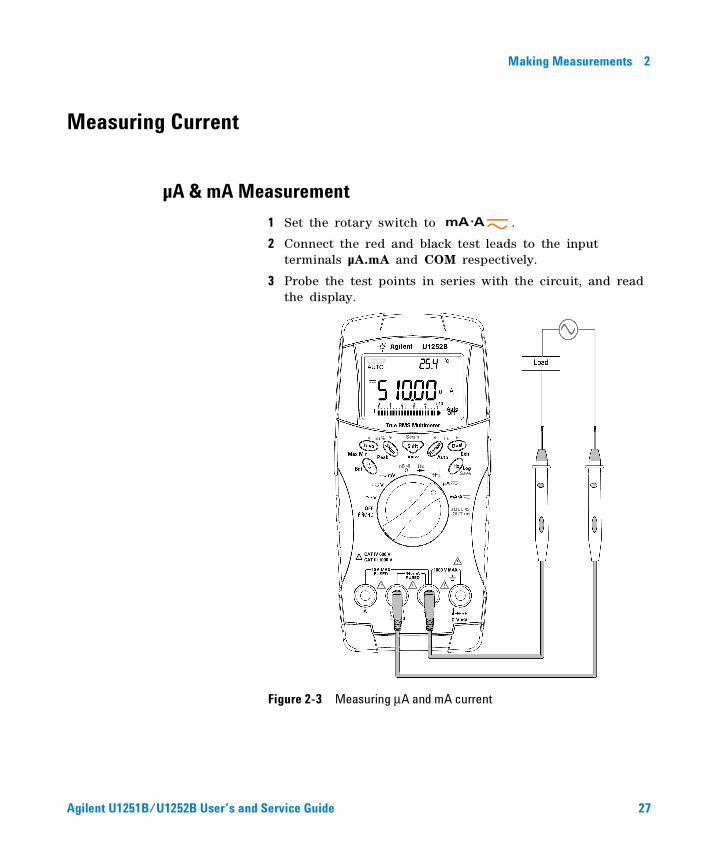
µA & mA Measurement
1 Set the rotary switch to .
2 Connect the red and black test leads to the input terminals µA.mA and COM respectively.
3 Probe the test points in series with the circuit, and read the display.
Figure 2-3 Measuring μA and mA current
Agilent U1251B/U1252B User’s and Service Guide 27
2 Making Measurements
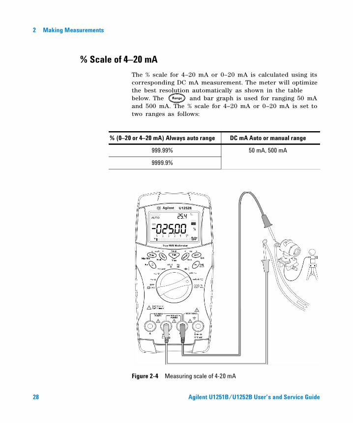
% Scale of 4–20 mA
The % scale for 4–20 mA or 0–20 mA is calculated using its corresponding DC mA measurement. The meter will optimize the best resolution automatically as shown in the table below. The and bar graph is used for ranging 50 mA and 500 mA. The % scale for 4–20 mA or 0–20 mA is set to two ranges as follows:
Figure 2-4 Measuring scale of 4-20 mA
% (0–20 or 4–20 mA) Always auto range DC mA Auto or manual range
999.99% 50 mA, 500 mA
9999.9%
28 Agilent U1251B/U1252B User’s and Service Guide
Making Measurements 2
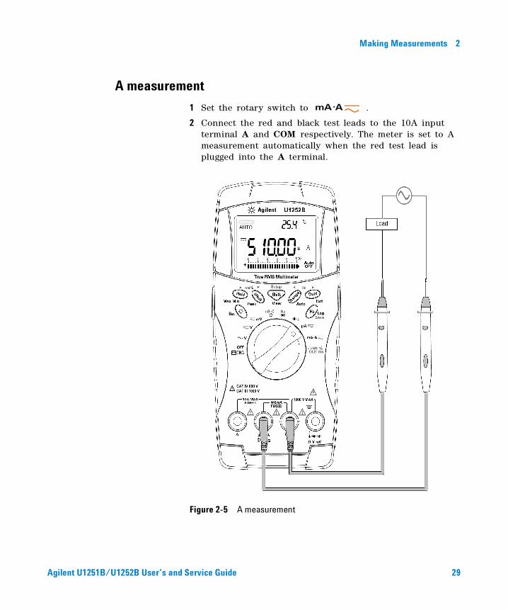
A measurement
1 Set the rotary switch to .
2 Connect the red and black test leads to the 10A input terminal A and COM respectively. The meter is set to A measurement automatically when the red test lead is plugged into the A terminal.
Figure 2-5 A measurement
Agilent U1251B/U1252B User’s and Service Guide 29
2 Making Measurements
Frequency Counter
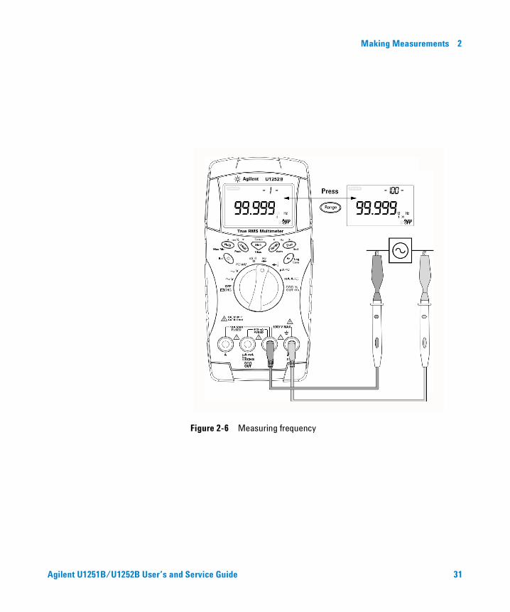
1 Set the rotary switch to .
2 Press to select the Frequency counter (Hz) function. “- 1- “ on the secondary display means the input signal frequency is divided by 1. This accommodates for a higher frequency range of up to 985 kHz.
3 Connect the red and black test leads to the input terminals V and COM respectively.
4 Probe the test points and read the display.
5 If the reading is unstable or is zero, press to select the division of the input signal frequency by 100. This accommodates for a higher frequency range of up to 20 MHz.
6 The signal is out of range if the reading is still unstable after Step 5.
While the secondary display shows “- 1- “, you may scroll through the pulse width (ms), duty cycle (%) and frequency (Hz) measurements by pressing .
WARNING • Use the frequency counter for low voltage applications only. Never use the frequency counter for line power system.
• For input more than 30 Vpp, you are required to use frequency measurement mode available under the current or voltage measurement instead of frequency counter.
30 Agilent U1251B/U1252B User’s and Service Guide
Making Measurements 2
Figure 2-6 Measuring frequency
Agilent U1251B/U1252B User’s and Service Guide 31
2 Making Measurements
Measuring Resistance, Conductance and Testing Continuity
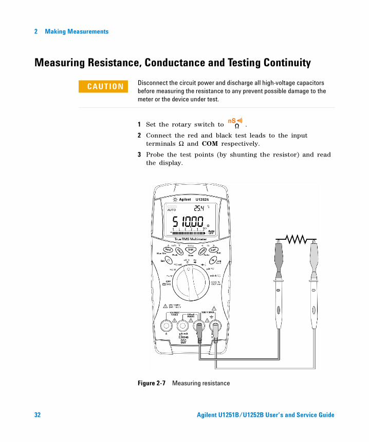
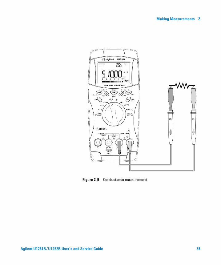
1 Set the rotary switch to .
2 Connect the red and black test leads to the input terminals Ω and COM respectively.
3 Probe the test points (by shunting the resistor) and read the display.
Figure 2-7 Measuring resistance
CAUTION Disconnect the circuit power and discharge all high-voltage capacitors before measuring the resistance to any prevent possible damage to the meter or the device under test.
32 Agilent U1251B/U1252B User’s and Service Guide
Making Measurements 2
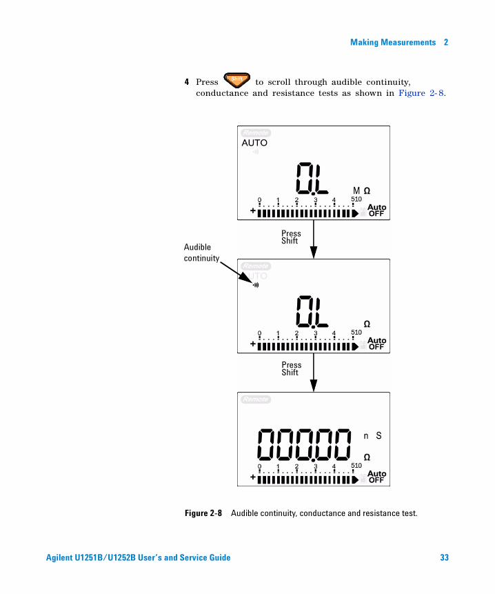
4 Press to scroll through audible continuity, conductance and resistance tests as shown in Figure 2- 8.
Figure 2-8 Audible continuity, conductance and resistance test.
Audible continuity
Press Shift
Press Shift
Agilent U1251B/U1252B User’s and Service Guide 33
2 Making Measurements
In the range of 0–500 Ω, the beeper will sound if the resistance value falls below 10 Ω. For other ranges, the beeper will sound if the resistance falls below the typical values indicated in the table below.
The conductance measurement enables the measurement of very high resistance of up to 100 GΩ. As the high- resistance readings are susceptible to noise, you can capture the average readings by using the Dynamic Recording mode. See Figure 3- 1 on page 47.
Measuring range Beeper sounds when
500.00 Ω Ω < 10
5.0000 kΩ Ω < 100
50.000 kΩ Ω < 1k
500.00 kΩ Ω < 10k
5.0000 MΩ Ω < 100k
50.000 MΩ Ω < 1M
500.00 MΩ Ω < 10M
34 Agilent U1251B/U1252B User’s and Service Guide
Making Measurements 2
Figure 2-9 Conductance measurement
Agilent U1251B/U1252B User’s and Service Guide 35
2 Making Measurements
Testing Diodes
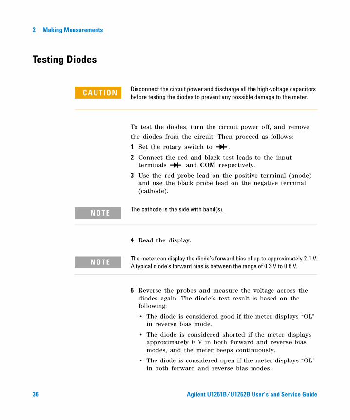
To test the diodes, turn the circuit power off, and remove
the diodes from the circuit. Then proceed as follows:
1 Set the rotary switch to .
2 Connect the red and black test leads to the input terminals and COM respectively.
3 Use the red probe lead on the positive terminal (anode) and use the black probe lead on the negative terminal (cathode).
4 Read the display.
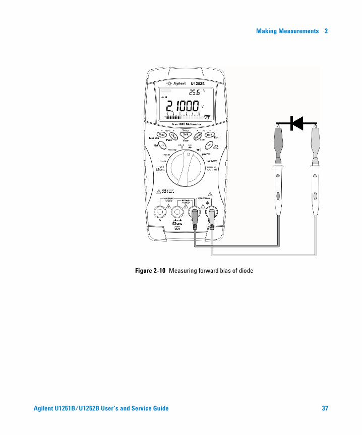
5 Reverse the probes and measure the voltage across the diodes again. The diode’s test result is based on the following:
• The diode is considered good if the meter displays “OL” in reverse bias mode.
• The diode is considered shorted if the meter displays approximately 0 V in both forward and reverse bias modes, and the meter beeps continuously.
• The diode is considered open if the meter displays “OL” in both forward and reverse bias modes.
CAUTION Disconnect the circuit power and discharge all the high-voltage capacitors before testing the diodes to prevent any possible damage to the meter.
NOTE The cathode is the side with band(s).
NOTE The meter can display the diode’s forward bias of up to approximately 2.1 V.A typical diode’s forward bias is between the range of 0.3 V to 0.8 V.
36 Agilent U1251B/U1252B User’s and Service Guide
Making Measurements 2
Figure 2-10 Measuring forward bias of diode
Agilent U1251B/U1252B User’s and Service Guide 37
2 Making Measurements
Figure 2-11 Measuring reverse bias of diode
.
38 Agilent U1251B/U1252B User’s and Service Guide
Making Measurements 2
Measuring Capacitance
The meter measures capacitance by charging the capacitor with a known current for a period of time, measuring the voltage and then calculating the capacitance. The larger the capacitor, the longer is the charging time.
Measuring tips:
• For measuring capacitances greater than 10,000µF, discharge the capacitor first, then select a suitable range for the measurement. This will speed up measuring time in order to obtain the correct capacitance value.
• For measuring small capacitances, press with the test leads open to subtract any residual capacitance from the meter or the leads.
1 Set the rotary switch to .
2 Connect the red and black test leads to the input terminals and COM respectively.
3 Use the red probe lead on the positive terminal of the capacitor and use the black probe lead on the negative terminal.
4 Read the display.
CAUTION Disconnect the circuit power and discharge all the high-voltage capacitors before measuring the capacitance to prevent any possible damage to the meter or the device under test. To confirm that the capacitors have discharged, use the DC voltage function.
NOTE means the capacitor is charging. means the capacitor is discharging.
Agilent U1251B/U1252B User’s and Service Guide 39
2 Making Measurements
Measuring Temperature
The bead type thermocouple probe is suitable for making temperature measurements between –20 °C to 200 °C in Teflon compatible environments. Above this temperature, the probe may emit a toxic gas. Do not immerse this thermocouple probe in liquids. For best results, use a thermocouple probe designed for each application — an immersion probe for liquid or gel and an air probe for air measurements. Observe the following measuring techniques:
• Clean the measurement surface and make sure the probe is securely touching the surface. Remember to disable the applied power.
• When measuring above the ambient temperature, move the thermocouple along the surface until you get the highest temperature reading.
• When measuring below ambient temperature, move the thermocouple along the surface until you get the lowest temperature reading.
• Place the meter in the operating environment for at least 1 hour as using non- compensation transfer adaptor with miniature thermal probe.
• For a quick measurement, use the 0 °C compensation to see the temperature variation of the thermocouple sensor. The 0 °C compensation assists in measuring the relative temperature immediately.
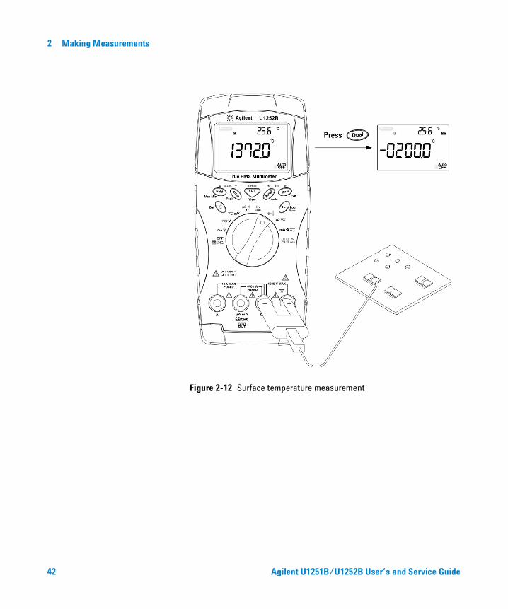
1 Turn the rotary switch to position.
2 Press to select the temperature measurement.
3 Plug the thermocouple adapter (with the thermocouple probe connected to it) into the input terminals and COM.
CAUTION Do not bend the thermocouple leads at sharp angles. Repeated bendingover a period of time may break the leads.
40 Agilent U1251B/U1252B User’s and Service Guide
Making Measurements 2
4 Touch the measurement surface with the thermocouple probe.
5 Read the display.
If you are working in a varied environment, where the ambient temperature is not constant, do the following:
1 Press to select 0 °C compensation. This gives a quick measurement of the relative temperature.
2 Avoid contact between the thermocouple probe and the measurement surface.
3 After a constant reading is obtained, press to set the reading as the relative reference temperature.
4 Touch the measurement surface with the thermocouple probe.
5 Read the display for the relative temperature.
Agilent U1251B/U1252B User’s and Service Guide 41
2 Making Measurements
Figure 2-12 Surface temperature measurement
42 Agilent U1251B/U1252B User’s and Service Guide
Making Measurements 2
Alerts and Warning During Measurement
Overload Alert
The meter provides an overload alert for voltage measurement in both auto and manual range modes. The meter beeps periodically once the measuring voltage exceeds 1010 V. For your safety, please be aware of this alert.
Input Warning
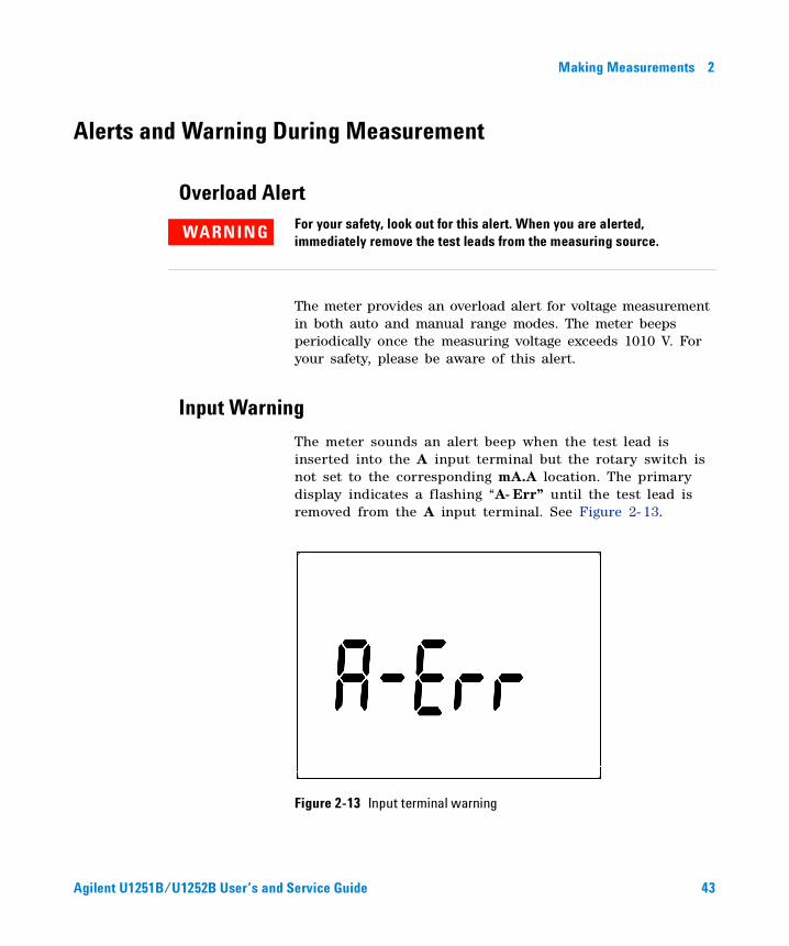
The meter sounds an alert beep when the test lead is inserted into the A input terminal but the rotary switch is not set to the corresponding mA.A location. The primary display indicates a flashing “A- Err” until the test lead is removed from the A input terminal. See Figure 2- 13.
Figure 2-13 Input terminal warning
WARNING For your safety, look out for this alert. When you are alerted, immediately remove the test leads from the measuring source.
Agilent U1251B/U1252B User’s and Service Guide 43
2 Making Measurements
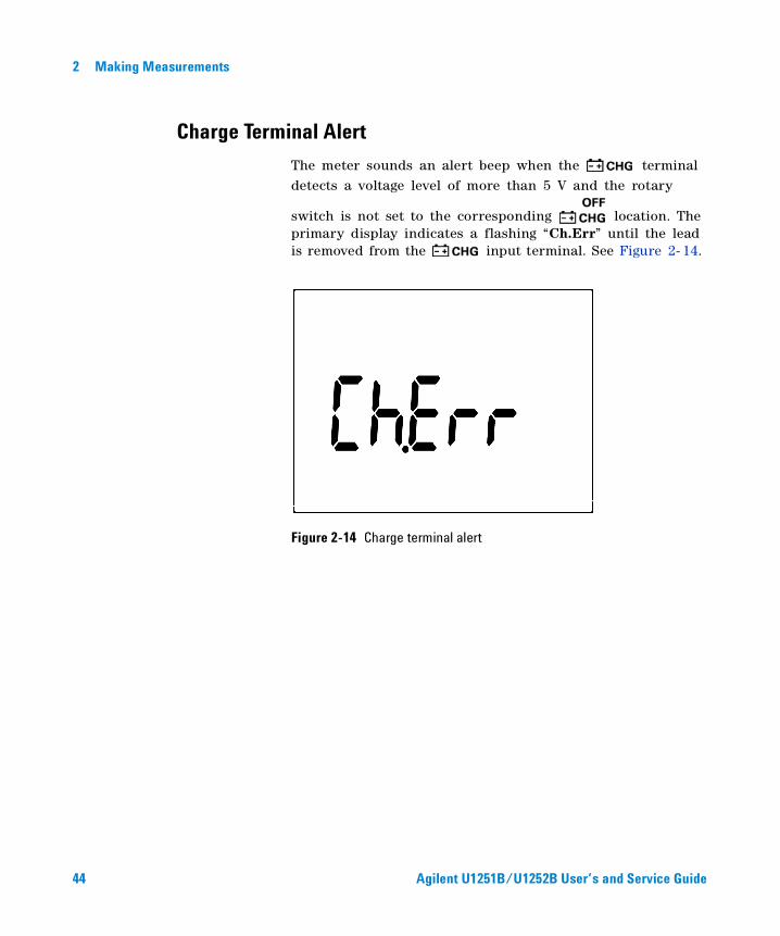
Charge Terminal Alert
The meter sounds an alert beep when the terminal detects a voltage level of more than 5 V and the rotary
switch is not set to the corresponding location. The primary display indicates a flashing “Ch.Err” until the lead is removed from the input terminal. See Figure 2- 14.
Figure 2-14 Charge terminal alert
44 Agilent U1251B/U1252B User’s and Service Guide
Agilent U1251B and U1252B Handheld Digital Multimeter User’s and Service Guide
3Features and Functions
Dynamic Recording 46
Data Hold (Trigger Hold) 48
Refresh Hold 49
Null (Relative) 51
Decibel Display 53
1 ms Peak Hold 55
Data Logging 57
Manual Logging 57
Interval Logging 59
Reviewing Logged Data 61
Square Wave Output (for U1252B) 63
Remote Communication 67
This chapter contains detailed information on the features and functions that are available in this meter.
45Agilent Technologies
3 Features and Functions
Dynamic Recording
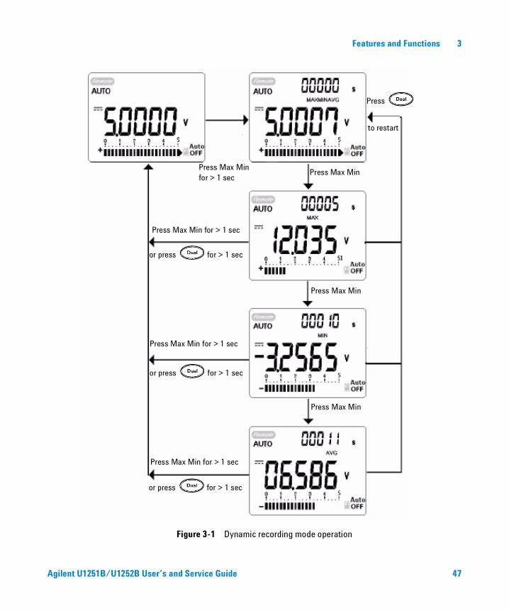
The Dynamic Recording mode detects intermittent turn on or turn off voltage or current surges and verifies the measuring performance without the user being present during any particular period of time. You can take readings simultaneously while performing other task.
Use the average reading procedure to even out unstable inputs, estimating the percentage in time a circuit is operated, and verifying the circuit performance. The secondary display shows the time lapse. The maximum time is 99,999 seconds. When this maximum time is exceeded, the display indicates “OL”.
1 Press for more than 1 second to enter Dynamic Recording mode. The meter is now in continuous mode or non- data hold (non- trigger) mode. “MAXMINAVG” and present value of measurement are displayed. The beeper sounds when a new maximum or minimum value is recorded.
2 Press to cycle through maximum, minimum, average and present readings. The MAX, MIN, AVG and MAXMINAVG indicators light up, corresponding to the displayed readings.
3 Press or for more than 1 second to exit Dynamic Recording mode.
NOTE • Press to restart the dynamic recording.
• The average value is the true average of all the measured values taken in the Dynamic Recording mode. If an overload is recorded, the averaging function will stop and the average value becomes "OL"(overload). is disabled in Dynamic Recording mode.
46 Agilent U1251B/U1252B User’s and Service Guide
Features and Functions 3
Figure 3-1 Dynamic recording mode operation
Press Max Min for > 1 sec
Press Max Min for > 1 sec
or press for > 1 sec
Press Max Min for > 1 sec
Press Max Min for > 1 sec
Press
to restart
Press Max Min
or press for > 1 sec
or press for > 1 sec
Press Max Min
Press Max Min
Agilent U1251B/U1252B User’s and Service Guide 47
3 Features and Functions
Data Hold (Trigger Hold)
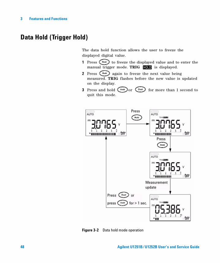
The data hold function allows the user to freeze the displayed digital value.
1 Press to freeze the displayed value and to enter the manual trigger mode. TRIG is displayed.
2 Press again to freeze the next value being measured. TRIG flashes before the new value is updated on the display.
3 Press and hold or for more than 1 second to quit this mode.
Figure 3-2 Data hold mode operation
Measurement update
Press or
press for > 1 sec.
Press
Press
48 Agilent U1251B/U1252B User’s and Service Guide
Features and Functions 3
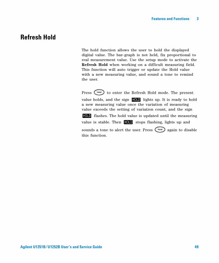
Refresh Hold
The hold function allows the user to hold the displayed digital value. The bar- graph is not held, fix proportional to real measurement value. Use the setup mode to activate the Refresh Hold when working on a difficult measuring field. This function will auto trigger or update the Hold value with a new measuring value, and sound a tone to remind the user.
Press to enter the Refresh Hold mode. The present
value holds, and the sign lights up. It is ready to hold a new measuring value once the variation of measuring value exceeds the setting of variation count, and the sign
flashes. The hold value is updated until the measuring
value is stable. Then stops flashing, lights up and
sounds a tone to alert the user. Press again to disable this function.
Agilent U1251B/U1252B User’s and Service Guide 49
Features and Functions 3
Agilent U1251B/U1252B User’s and Service Guide 50
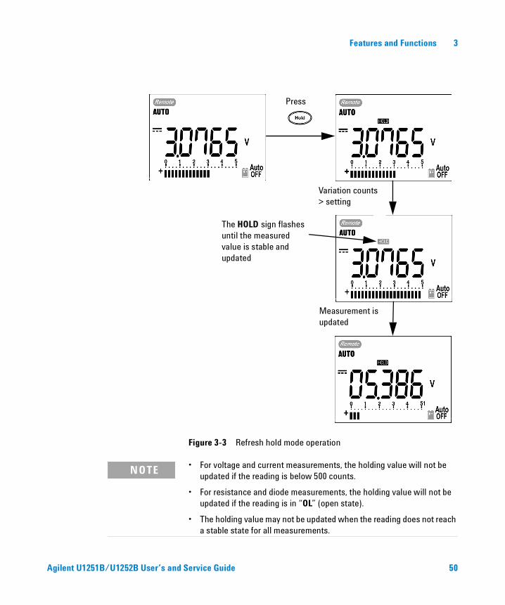
Figure 3-3 Refresh hold mode operation
The HOLD sign flashes until the measured value is stable and updated
Press
Variation counts > setting
Measurement is updated
NOTE • For voltage and current measurements, the holding value will not be updated if the reading is below 500 counts.
• For resistance and diode measurements, the holding value will not be updated if the reading is in “OL” (open state).
• The holding value may not be updated when the reading does not reach a stable state for all measurements.
Features and Functions 3
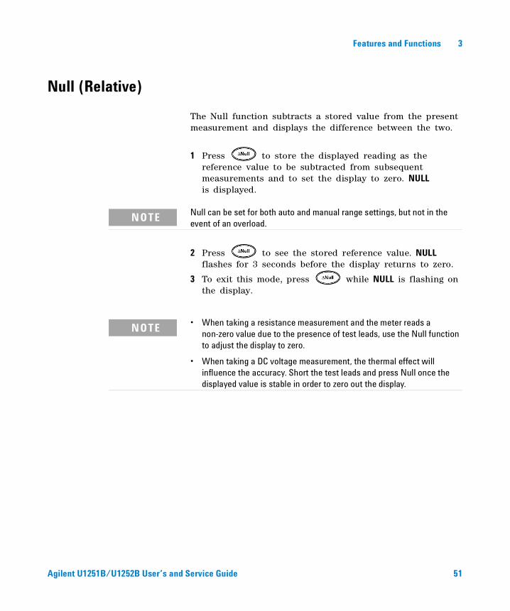
Null (Relative)
The Null function subtracts a stored value from the present measurement and displays the difference between the two.
1 Press to store the displayed reading as the reference value to be subtracted from subsequent measurements and to set the display to zero. NULL is displayed.
2 Press to see the stored reference value. NULL flashes for 3 seconds before the display returns to zero.
3 To exit this mode, press while NULL is flashing on the display.
NOTE Null can be set for both auto and manual range settings, but not in the event of an overload.
NOTE • When taking a resistance measurement and the meter reads a non-zero value due to the presence of test leads, use the Null function to adjust the display to zero.
• When taking a DC voltage measurement, the thermal effect will influence the accuracy. Short the test leads and press Null once the displayed value is stable in order to zero out the display.
Agilent U1251B/U1252B User’s and Service Guide 51
3 Features and Functions
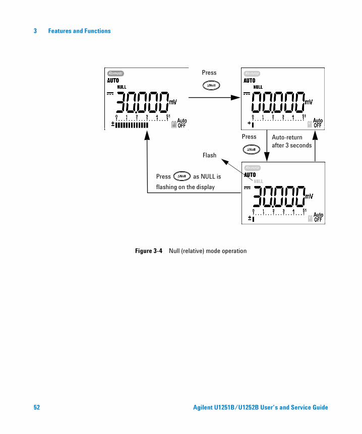
Figure 3-4 Null (relative) mode operation
Press
Press as NULL is
flashing on the display
Press Auto-return after 3 seconds
Flash
52 Agilent U1251B/U1252B User’s and Service Guide
Features and Functions 3
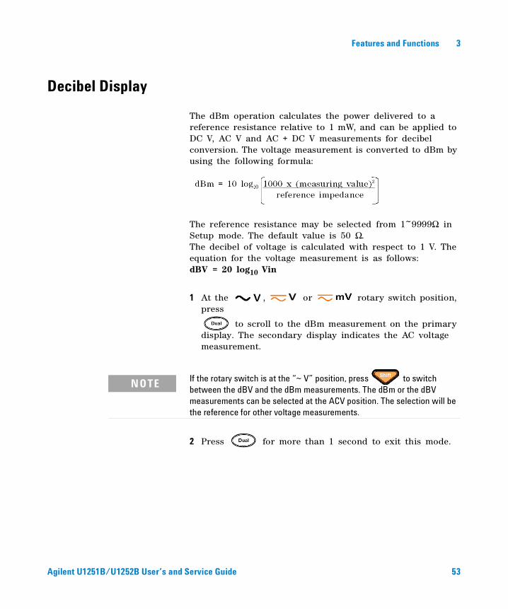
Decibel Display
The dBm operation calculates the power delivered to a reference resistance relative to 1 mW, and can be applied to DC V, AC V and AC + DC V measurements for decibel conversion. The voltage measurement is converted to dBm by using the following formula:
The reference resistance may be selected from 1~9999Ω in Setup mode. The default value is 50 Ω.The decibel of voltage is calculated with respect to 1 V. The equation for the voltage measurement is as follows:dBV = 20 log10 Vin
1 At the , or rotary switch position, press
to scroll to the dBm measurement on the primary display. The secondary display indicates the AC voltage measurement.
2 Press for more than 1 second to exit this mode.
NOTE If the rotary switch is at the “~ V” position, press to switch between the dBV and the dBm measurements. The dBm or the dBV measurements can be selected at the ACV position. The selection will be the reference for other voltage measurements.
Agilent U1251B/U1252B User’s and Service Guide 53
3 Features and Functions
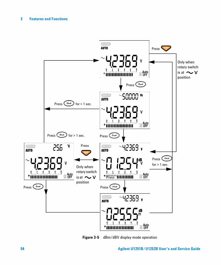
Figure 3-5 dBm/dBV display mode operation
Press
Press
Press
Press
Press for > 1 sec.
Press for > 1 sec.
Only when rotary switch is at position
Only when rotary switch is at position
Press
Press
for > 1 sec.
Press
Press
54 Agilent U1251B/U1252B User’s and Service Guide
Features and Functions 3
1 ms Peak Hold
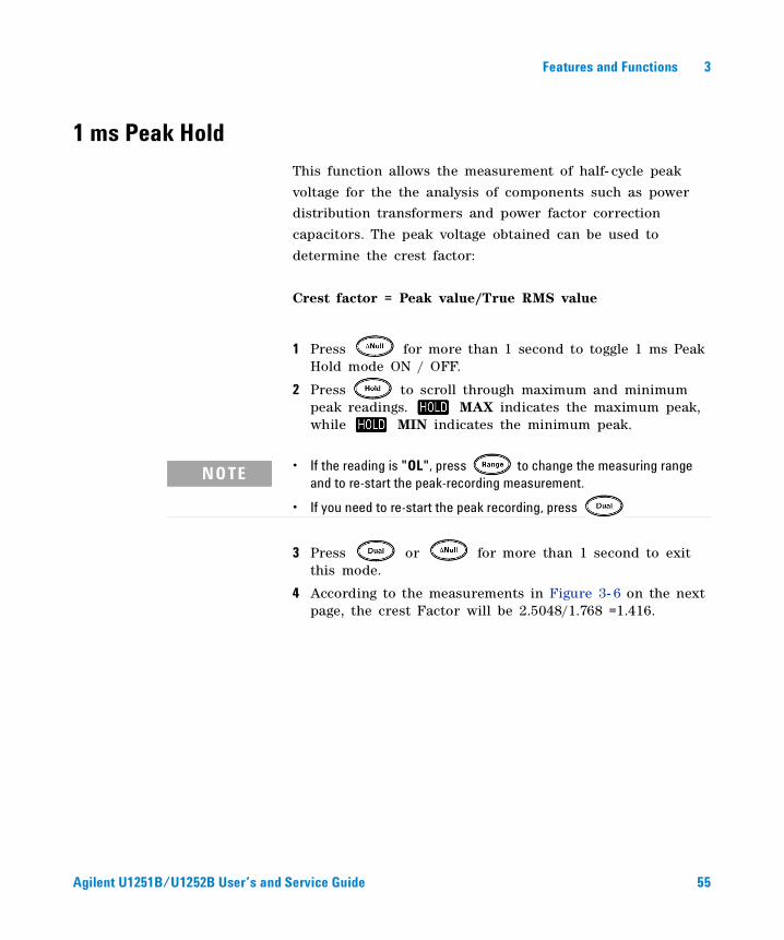
This function allows the measurement of half- cycle peak
voltage for the the analysis of components such as power
distribution transformers and power factor correction
capacitors. The peak voltage obtained can be used to
determine the crest factor:
Crest factor = Peak value/True RMS value
1 Press for more than 1 second to toggle 1 ms Peak Hold mode ON / OFF.
2 Press to scroll through maximum and minimum peak readings. MAX indicates the maximum peak, while MIN indicates the minimum peak.
3 Press or for more than 1 second to exit this mode.
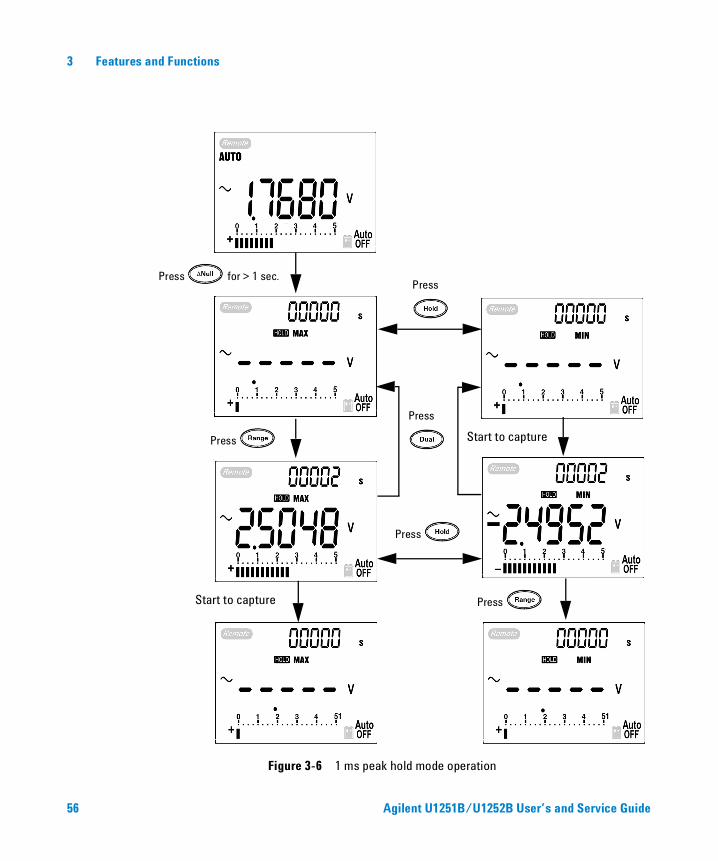
4 According to the measurements in Figure 3- 6 on the next page, the crest Factor will be 2.5048/1.768 =1.416.
NOTE • If the reading is "OL", press to change the measuring range and to re-start the peak-recording measurement.
• If you need to re-start the peak recording, press
Agilent U1251B/U1252B User’s and Service Guide 55
3 Features and Functions
Figure 3-6 1 ms peak hold mode operation
Press for > 1 sec.
Press
Press
Press
Press
Press Start to capture
Start to capture
56 Agilent U1251B/U1252B User’s and Service Guide
Features and Functions 3
Data Logging
The Data logging function makes it easy to record test data
for future review or analysis. Since data are stored in the
non- volatile memory, they are retained when the meter is
turned OFF or when the battery is changed. There are two
options - hand (manual) logging and interval (automatic)
logging. Data logging records the values on primary display
only.
Manual Logging
Hand (Manual) logging can be specified in Setup mode.
1 Press for more than 1 second to store the presentvalue and function on the primary display to the
non- volatile memory. and the logging index are
indicated. The logging index flashes on the secondary
display for 3 seconds before returning to normal display.
2 Press again to save the next value into the permanent memory.
Agilent U1251B/U1252B User’s and Service Guide 57
3 Features and Functions
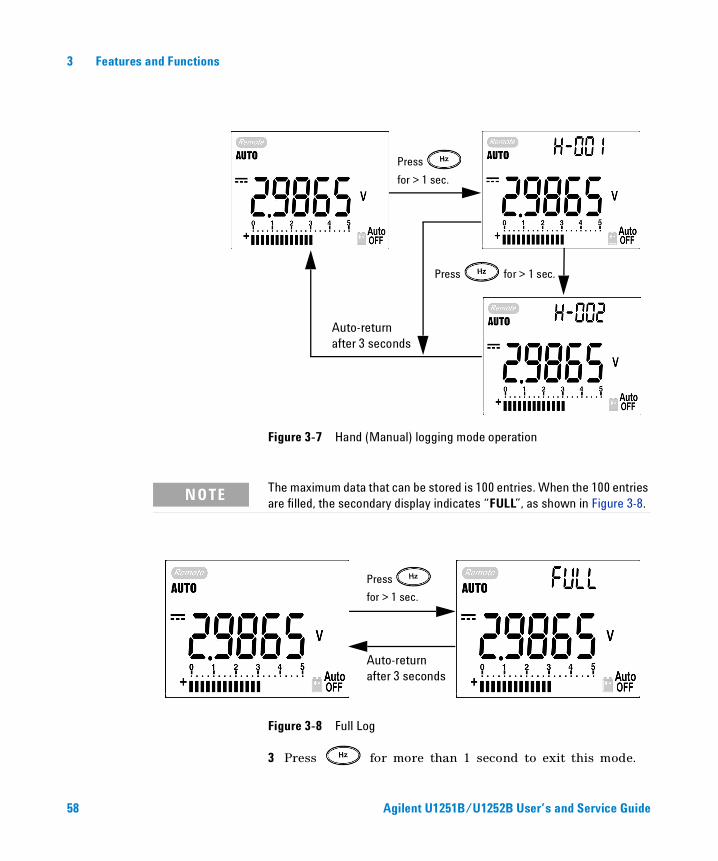
Figure 3-7 Hand (Manual) logging mode operation
Figure 3-8 Full Log
3 Press for more than 1 second to exit this mode.
Press
for > 1 sec.
Press for > 1 sec.
Auto-return after 3 seconds
NOTE The maximum data that can be stored is 100 entries. When the 100 entries are filled, the secondary display indicates “FULL”, as shown in Figure 3-8.
Auto-return after 3 seconds
Press
for > 1 sec.
58 Agilent U1251B/U1252B User’s and Service Guide
Features and Functions 3
Interval Logging
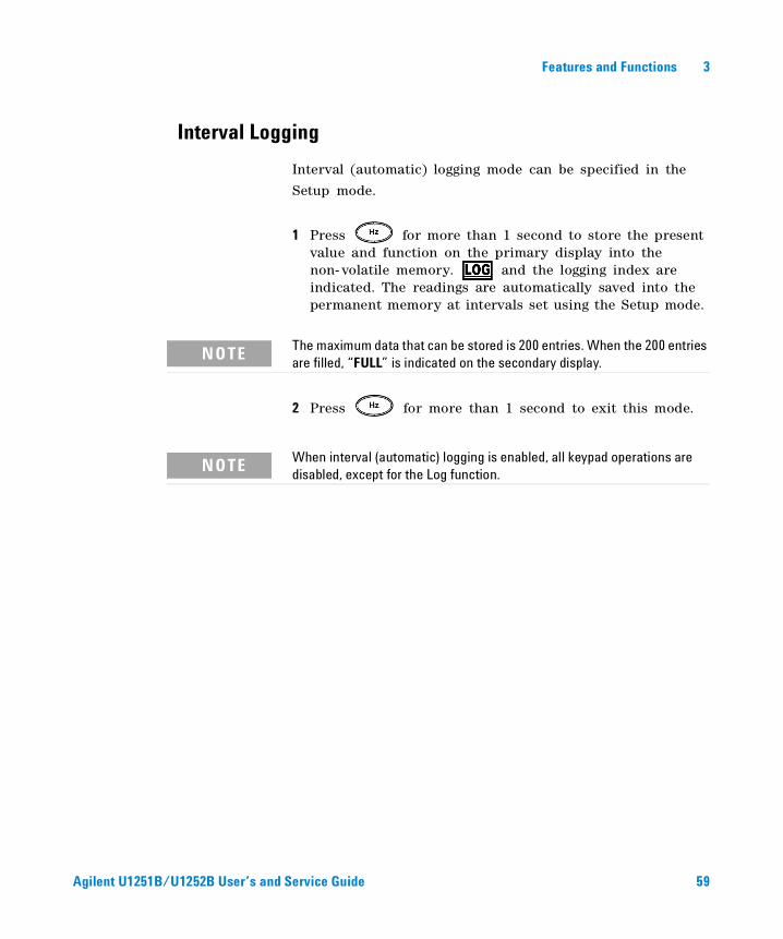
Interval (automatic) logging mode can be specified in the
Setup mode.
1 Press for more than 1 second to store the present value and function on the primary display into the non- volatile memory. and the logging index are indicated. The readings are automatically saved into the permanent memory at intervals set using the Setup mode.
2 Press for more than 1 second to exit this mode.
NOTE The maximum data that can be stored is 200 entries. When the 200 entries are filled, “FULL” is indicated on the secondary display.
NOTE When interval (automatic) logging is enabled, all keypad operations are disabled, except for the Log function.
Agilent U1251B/U1252B User’s and Service Guide 59
3 Features and Functions
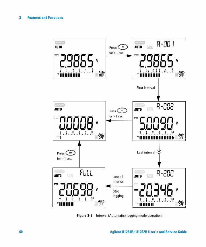
Figure 3-9 Interval (Automatic) logging mode operation
Press
for > 1 sec.
Press
for > 1 sec.
Press
for > 1 sec.
First interval
Last interval
Last +1 interval
Stop logging
60 Agilent U1251B/U1252B User’s and Service Guide
Features and Functions 3
Reviewing Logged Data
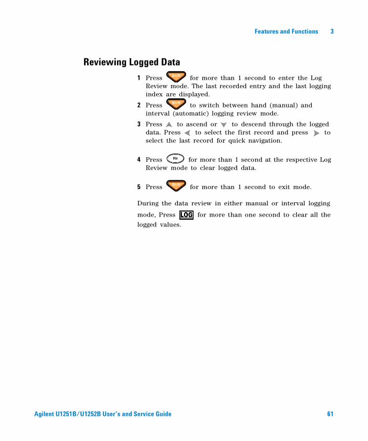
1 Press for more than 1 second to enter the Log Review mode. The last recorded entry and the last logging index are displayed.
2 Press to switch between hand (manual) and interval (automatic) logging review mode.
3 Press to ascend or to descend through the logged data. Press to select the first record and press to select the last record for quick navigation.
4 Press for more than 1 second at the respective Log Review mode to clear logged data.
5 Press for more than 1 second to exit mode.
During the data review in either manual or interval logging
mode, Press for more than one second to clear all the
logged values.
Agilent U1251B/U1252B User’s and Service Guide 61
3 Features and Functions
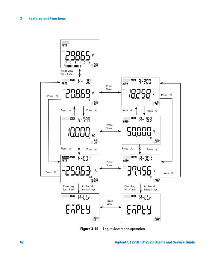
Figure 3-10 Log review mode operation
Press View for > 1 sec.
Press View
Press
Press
Press
Press
Press
Press Press
Press Press Press
Press
Press
Press Log for > 1 sec
to clear all manual logs
Press Log for > 1 sec
to clear all interval logs
Press View
Press View
Press View
62 Agilent U1251B/U1252B User’s and Service Guide
Features and Functions 3
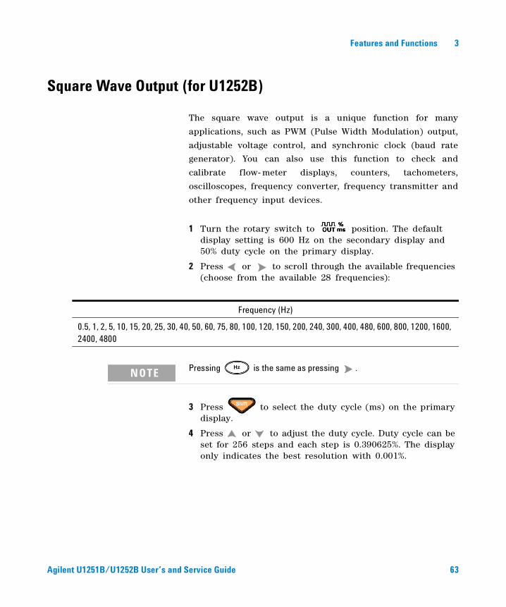
Square Wave Output (for U1252B)
The square wave output is a unique function for many
applications, such as PWM (Pulse Width Modulation) output,
adjustable voltage control, and synchronic clock (baud rate
generator). You can also use this function to check and
calibrate flow- meter displays, counters, tachometers,
oscilloscopes, frequency converter, frequency transmitter and
other frequency input devices.
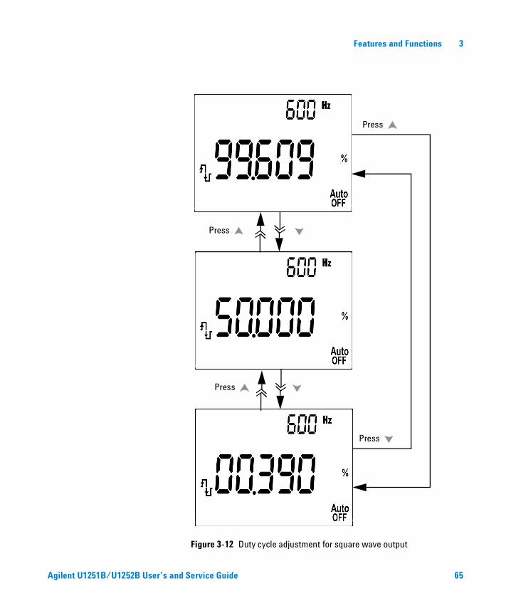
1 Turn the rotary switch to position. The default display setting is 600 Hz on the secondary display and 50% duty cycle on the primary display.
2 Press or to scroll through the available frequencies (choose from the available 28 frequencies):
3 Press to select the duty cycle (ms) on the primary display.
4 Press or to adjust the duty cycle. Duty cycle can be set for 256 steps and each step is 0.390625%. The display only indicates the best resolution with 0.001%.
Frequency (Hz)
0.5, 1, 2, 5, 10, 15, 20, 25, 30, 40, 50, 60, 75, 80, 100, 120, 150, 200, 240, 300, 400, 480, 600, 800, 1200, 1600, 2400, 4800
NOTE Pressing is the same as pressing .
Agilent U1251B/U1252B User’s and Service Guide 63
3 Features and Functions
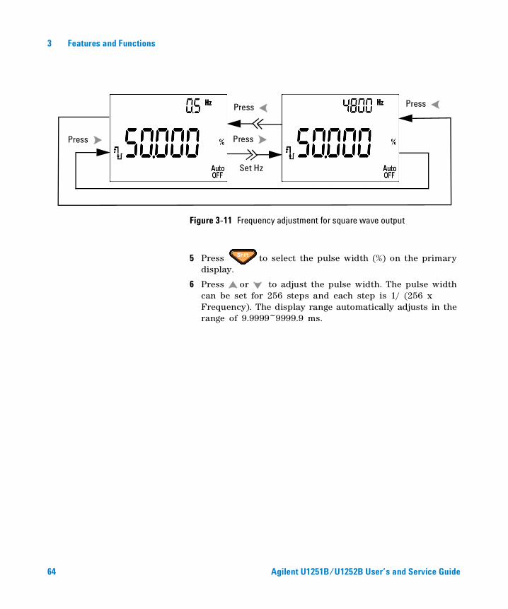
Figure 3-11 Frequency adjustment for square wave output
5 Press to select the pulse width (%) on the primary display.
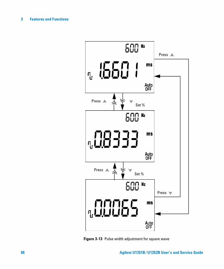
6 Press or to adjust the pulse width. The pulse width can be set for 256 steps and each step is 1/ (256 x Frequency). The display range automatically adjusts in the range of 9.9999~9999.9 ms.
Press Press
Press Press
Set Hz
64 Agilent U1251B/U1252B User’s and Service Guide
Features and Functions 3
Agilent U1251B/U1252B User’s and Service Guide 65
Figure 3-12 Duty cycle adjustment for square wave output
Press
Press
Press
Press
3 Features and Functions
Figure 3-13 Pulse width adjustment for square wave
Press
Press
Press
Press
Set %
Set %
66 Agilent U1251B/U1252B User’s and Service Guide
Features and Functions 3
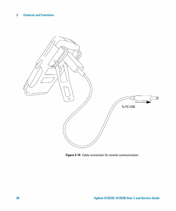
Remote Communication
The meter has a bi- directional (full duplex) communication capability that speeds data storing from the meter to the PC. To use this feature, you require the optional IR- USB cable, to be used with an application software that is downloadable from the Agilent Web site.
For details on performing PC- meter remote communication, click on Help after launching the Agilent GUI Data Logger Software.
Agilent U1251B/U1252B User’s and Service Guide 67
3 Features and Functions
Figure 3-14 Cable connection for remote communication
To PC USB
68 Agilent U1251B/U1252B User’s and Service Guide
Agilent U1251B and U1252B Handheld Digital MultimeterUser’s and Service Guide
4 Changing The Default Setting
Selecting Setup Mode 70
Setting Data Logging Mode 74
Setting Thermocouple Types (for U1252B) 75
Setting Reference Impedance for dBm Measurement 76
Setting Minimum Frequency Measurement 77
Setting Temperature Unit 78
Setting Auto Power Saving Mode 80
Setting % Scale Readout 82
Setting Beep Frequency 83
Setting Backlit Timer 84
Setting Baud Rate 85
Setting Parity Check 86
Setting Data Bit 87
Setting Echo Mode 88
Setting Print Mode 89
Returning to Default Factory Settings 90
Setting the Battery Voltage 91
Setting the DC Filter 92
This chapter describes how to change the default settings of the handheld digital multimeter, which includes data logging and other setting features.
69Agilent Technologies
4 Changing The Default Setting
Selecting Setup Mode
To enter the Setup mode, perform the following steps:
1 Turn the meter OFF.
2 From the OFF position, press and hold while turning the rotary switch to any non- OFF position.
To change a menu item setting in Setup mode, perform the following steps:
1 Press or to scroll through the menu items.
2 Press or to scroll through the available settings. See Table 3, “Available setting options in Setup mode,” for details of available options.
3 Press to save changes. These parameters will remain in the non- volatile memory.
4 Press for more than 1 second to exit Setup mode.
NOTE When you hear a beep, the meter is in Setup mode and you can release
.
70 Agilent U1251B/U1252B User’s and Service Guide
Changing The Default Setting 4
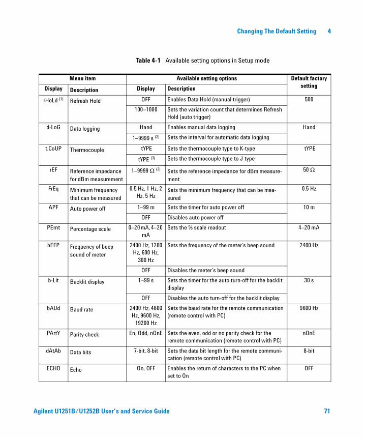
Table 4-1 Available setting options in Setup mode
Menu item Available setting options Default factory settingDisplay Description Display Description
rHoLd (1) Refresh Hold OFF Enables Data Hold (manual trigger) 500
100–1000 Sets the variation count that determines Refresh Hold (auto trigger)
d-LoG Data logging Hand Enables manual data logging Hand
1–9999 s (2) Sets the interval for automatic data logging
t.CoUP Thermocouple tYPE Sets the thermocouple type to K-type tYPE
tYPE (3) Sets the thermocouple type to J-type
rEF Reference impedance for dBm measurement
1–9999 Ω (2) Sets the reference impedance for dBm measure-ment
50 Ω
FrEq Minimum frequency that can be measured
0.5 Hz, 1 Hz, 2 Hz, 5 Hz
Sets the minimum frequency that can be mea-sured
0.5 Hz
APF Auto power off 1–99 m Sets the timer for auto power off 10 m
OFF Disables auto power off
PErnt Percentage scale 0–20 mA, 4–20 mA
Sets the % scale readout 4–20 mA
bEEP Frequency of beep sound of meter
2400 Hz, 1200 Hz, 600 Hz,
300 Hz
Sets the frequency of the meter’s beep sound 2400 Hz
OFF Disables the meter’s beep sound
b-Lit Backlit display 1–99 s Sets the timer for the auto turn-off for the backlit display
30 s
OFF Disables the auto turn-off for the backlit display
bAUd Baud rate 2400 Hz, 4800 Hz, 9600 Hz,
19200 Hz
Sets the baud rate for the remote communication (remote control with PC)
9600 Hz
PArtY Parity check En, Odd, nOnE Sets the even, odd or no parity check for the remote communication (remote control with PC)
nOnE
dAtAb Data bits 7-bit, 8-bit Sets the data bit length for the remote communi-cation (remote control with PC)
8-bit
ECHO Echo On, OFF Enables the return of characters to the PC when set to On
OFF
Agilent U1251B/U1252B User’s and Service Guide 71
4 Changing The Default Setting
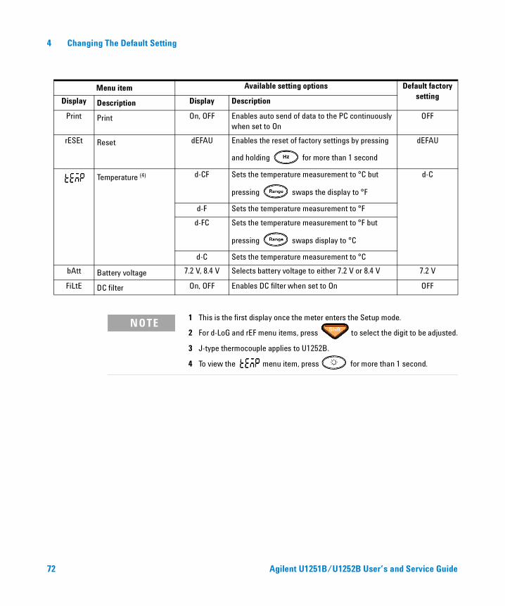
Menu item Available setting options Default factory setting
Display Description Display Description
Print Print On, OFF Enables auto send of data to the PC continuously when set to On
OFF
rESEt Reset dEFAU Enables the reset of factory settings by pressing
and holding for more than 1 second
dEFAU
Temperature (4) d-CF Sets the temperature measurement to °C but
pressing swaps the display to °F
d-C
d-F Sets the temperature measurement to °F
d-FC Sets the temperature measurement to °F but
pressing swaps display to °C
d-C Sets the temperature measurement to °C
bAtt Battery voltage 7.2 V, 8.4 V Selects battery voltage to either 7.2 V or 8.4 V 7.2 V
FiLtE DC filter On, OFF Enables DC filter when set to On OFF
NOTE1 This is the first display once the meter enters the Setup mode.
2 For d-LoG and rEF menu items, press to select the digit to be adjusted.
3 J-type thermocouple applies to U1252B.
4 To view the menu item, press for more than 1 second.
72 Agilent U1251B/U1252B User’s and Service Guide
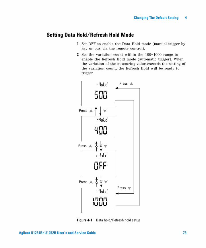
Changing The Default Setting 4
Setting Data Hold/Refresh Hold Mode
1 Set OFF to enable the Data Hold mode (manual trigger by key or bus via the remote control).
2 Set the variation count within the 100~1000 range to enable the Refresh Hold mode (automatic trigger). When the variation of the measuring value exceeds the setting of the variation count, the Refresh Hold will be ready to trigger.
Figure 4-1 Data hold/Refresh hold setup
Press
Press
Press
Press
Press
Agilent U1251B/U1252B User’s and Service Guide 73
4 Changing The Default Setting
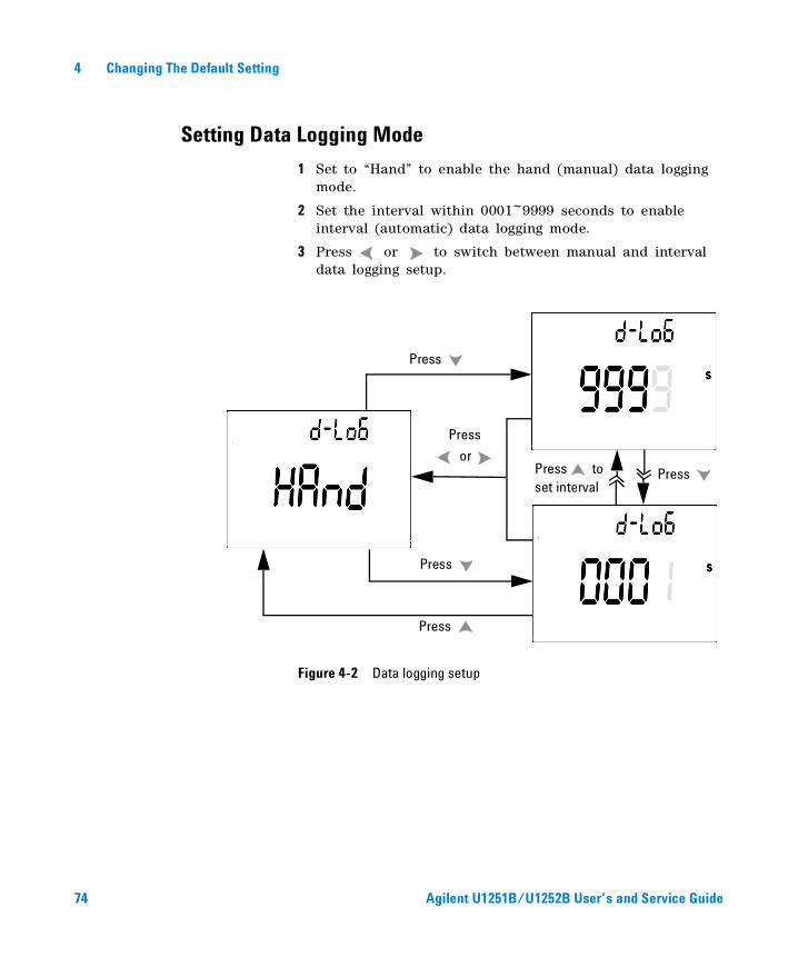
Setting Data Logging Mode
1 Set to “Hand” to enable the hand (manual) data logging mode.
2 Set the interval within 0001~9999 seconds to enable interval (automatic) data logging mode.
3 Press or to switch between manual and interval data logging setup.
Figure 4-2 Data logging setup
Press
Press
Press
Press
Press to set interval
Press
or
74 Agilent U1251B/U1252B User’s and Service Guide
Changing The Default Setting 4
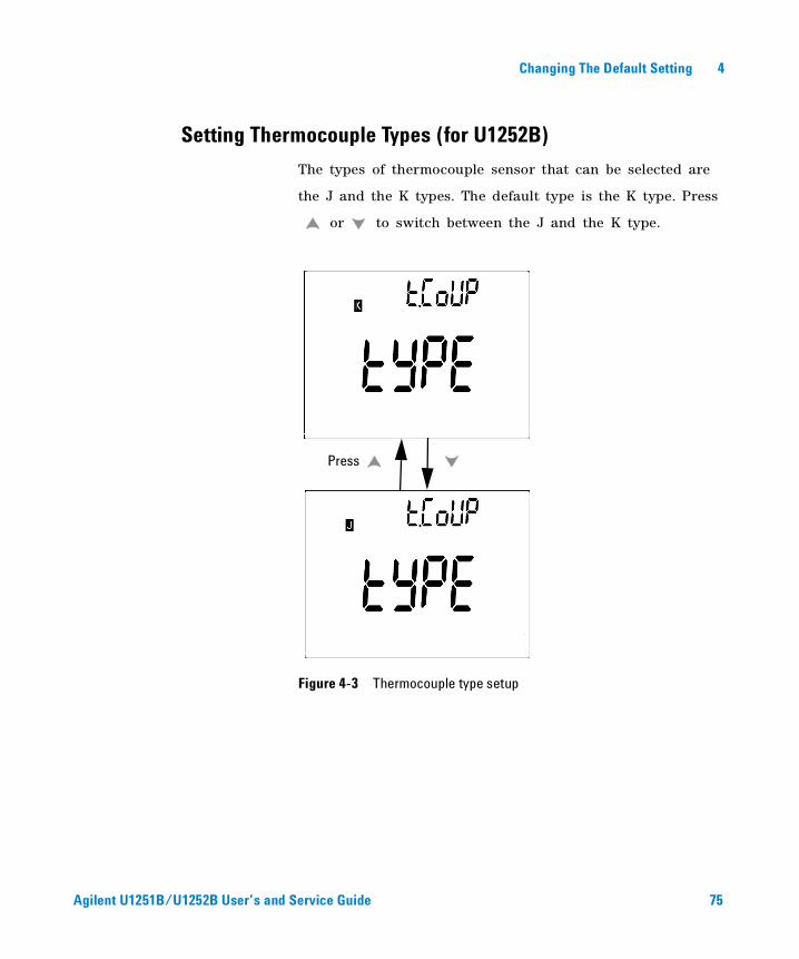
Setting Thermocouple Types (for U1252B)
The types of thermocouple sensor that can be selected are
the J and the K types. The default type is the K type. Press
or to switch between the J and the K type.
Figure 4-3 Thermocouple type setup
Press
Agilent U1251B/U1252B User’s and Service Guide 75
4 Changing The Default Setting
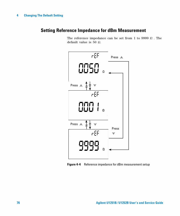
Setting Reference Impedance for dBm Measurement
The reference impedance can be set from 1 to 9999 W . The default value is 50 W.
Figure 4-4 Reference impedance for dBm measurement setup
Press
Press
Press Press
76 Agilent U1251B/U1252B User’s and Service Guide
Changing The Default Setting 4
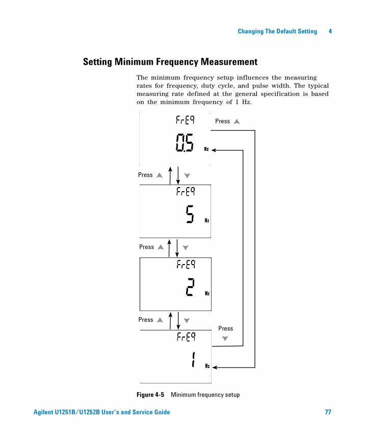
Setting Minimum Frequency Measurement
The minimum frequency setup influences the measuring rates for frequency, duty cycle, and pulse width. The typical measuring rate defined at the general specification is based on the minimum frequency of 1 Hz.
Figure 4-5 Minimum frequency setup
Press
Press
Press
Press Press
Agilent U1251B/U1252B User’s and Service Guide 77
4 Changing The Default Setting
Setting Temperature Unit
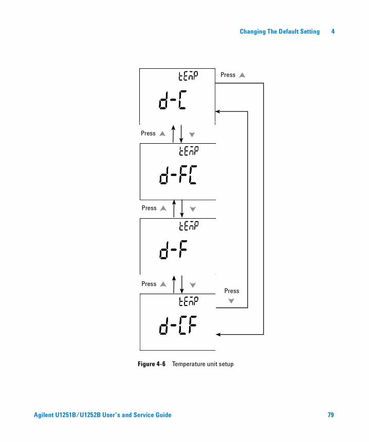
Four combination displays are available:
• Celsius only (°C on primary display) single display setting
• Celsius- Fahrenheit (d- CF) and Fahrenheit- Celsius (d- FC) dual display setting.
• Fahrenheit only (°F on primary display) single display setting.
NOTE Primary-Secondary Display can be swapped by pressing .
78 Agilent U1251B/U1252B User’s and Service Guide
Changing The Default Setting 4
Figure 4-6 Temperature unit setup
Press
Press
Press
Press
Press
Agilent U1251B/U1252B User’s and Service Guide 79
4 Changing The Default Setting
Setting Auto Power Saving Mode
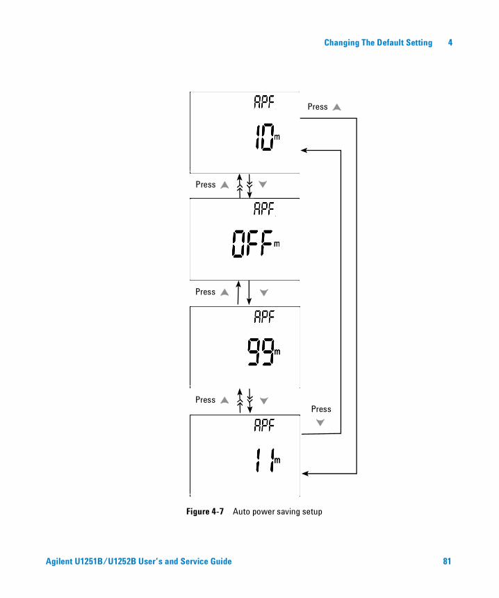
• The timer for APF (Auto Power OFF) can be set for the range of 1~99 minutes. To activate the meter after it has “auto power off”, turn the rotary switch to the OFF position, then turn it back on again.
• “OFF” disables APF. is indicated on the display during subsequent measurements.
80 Agilent U1251B/U1252B User’s and Service Guide
Changing The Default Setting 4
Figure 4-7 Auto power saving setup
Press
Press
Press
Press Press
Agilent U1251B/U1252B User’s and Service Guide 81
4 Changing The Default Setting
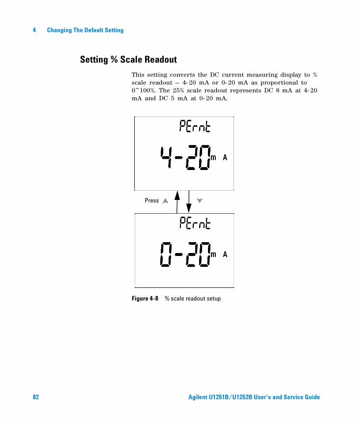
Setting % Scale Readout
This setting converts the DC current measuring display to % scale readout — 4- 20 mA or 0- 20 mA as proportional to 0~100%. The 25% scale readout represents DC 8 mA at 4- 20 mA and DC 5 mA at 0- 20 mA.
Figure 4-8 % scale readout setup
Press
82 Agilent U1251B/U1252B User’s and Service Guide
Changing The Default Setting 4
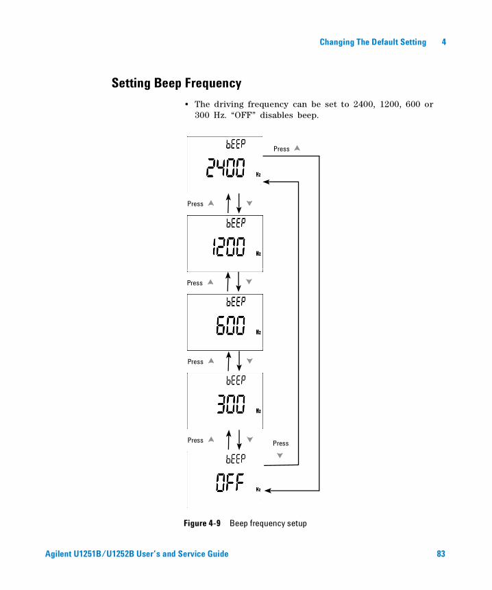
Setting Beep Frequency
• The driving frequency can be set to 2400, 1200, 600 or 300 Hz. “OFF” disables beep.
Figure 4-9 Beep frequency setup
Press
Press
Press
Press
Press
Press
Agilent U1251B/U1252B User’s and Service Guide 83
4 Changing The Default Setting
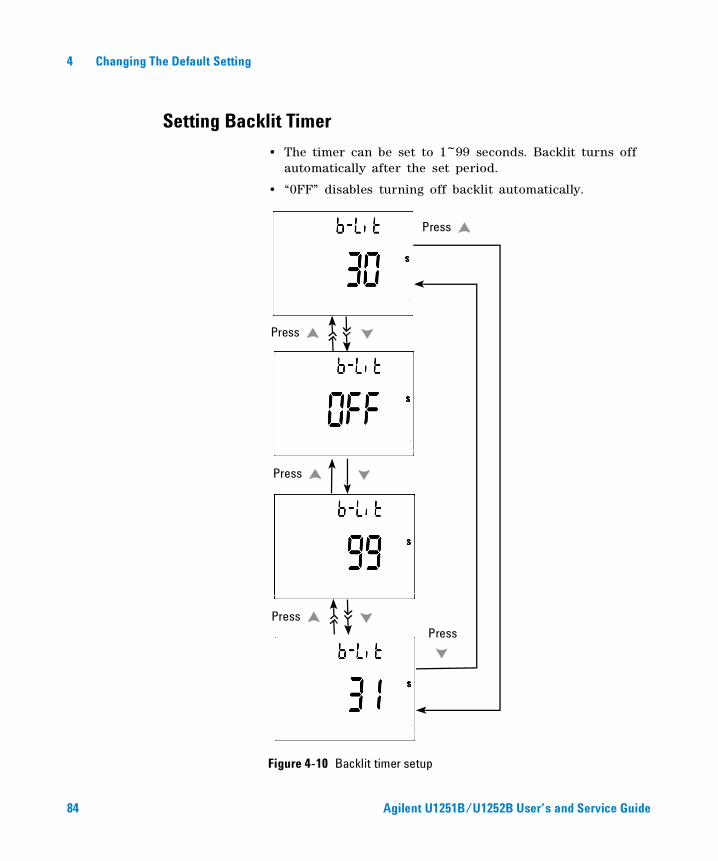
Setting Backlit Timer
• The timer can be set to 1~99 seconds. Backlit turns off automatically after the set period.
• “0FF” disables turning off backlit automatically.
Figure 4-10 Backlit timer setup
Press
Press
Press
Press Press
84 Agilent U1251B/U1252B User’s and Service Guide
Changing The Default Setting 4
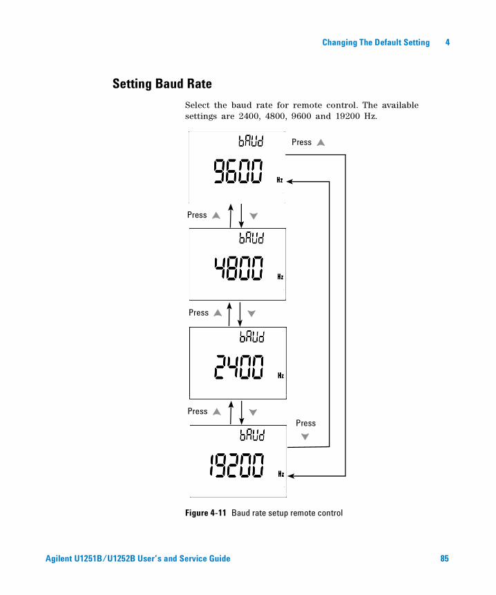
Setting Baud Rate
Select the baud rate for remote control. The available settings are 2400, 4800, 9600 and 19200 Hz.
Figure 4-11 Baud rate setup remote control
Press
Press
Press
Press Press
Agilent U1251B/U1252B User’s and Service Guide 85
4 Changing The Default Setting
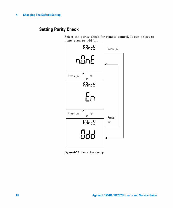
Setting Parity Check
Select the parity check for remote control. It can be set to none, even or odd bit.
Figure 4-12 Parity check setup
Press
Press
Press Press
86 Agilent U1251B/U1252B User’s and Service Guide
Changing The Default Setting 4
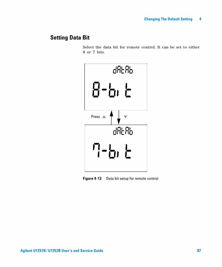
Setting Data Bit
Select the data bit for remote control. It can be set to either 8 or 7 bits.
Figure 4-13 Data bit setup for remote control
Press
Agilent U1251B/U1252B User’s and Service Guide 87
4 Changing The Default Setting
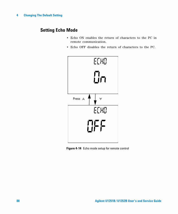
Setting Echo Mode
• Echo ON enables the return of characters to the PC in remote communication.
• Echo OFF disables the return of characters to the PC.
Figure 4-14 Echo mode setup for remote control
Press
88 Agilent U1251B/U1252B User’s and Service Guide
Changing The Default Setting 4
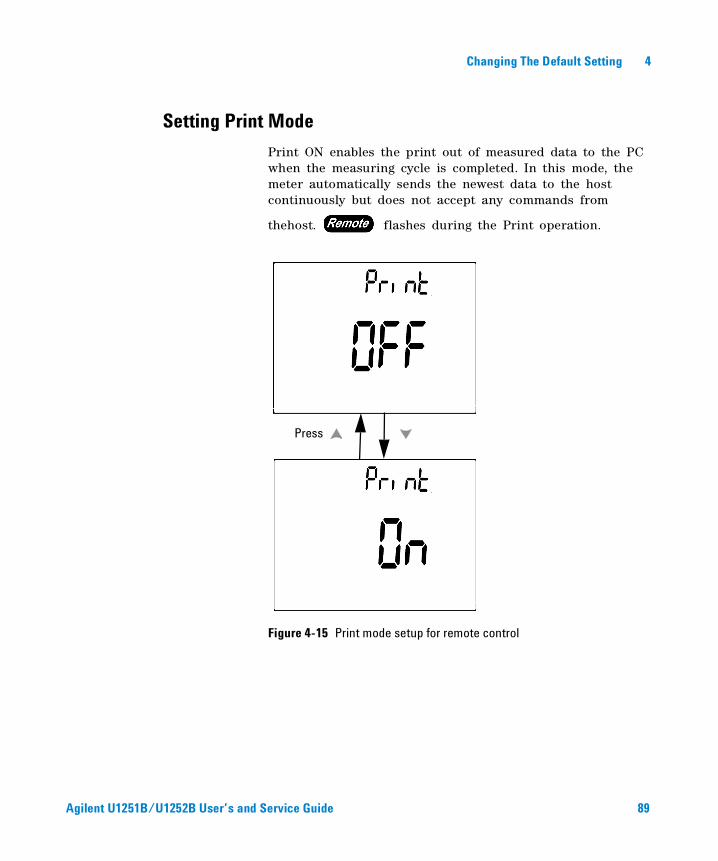
Setting Print Mode
Print ON enables the print out of measured data to the PC when the measuring cycle is completed. In this mode, the meter automatically sends the newest data to the host continuously but does not accept any commands from
thehost. flashes during the Print operation.
Figure 4-15 Print mode setup for remote control
Press
Agilent U1251B/U1252B User’s and Service Guide 89
4 Changing The Default Setting
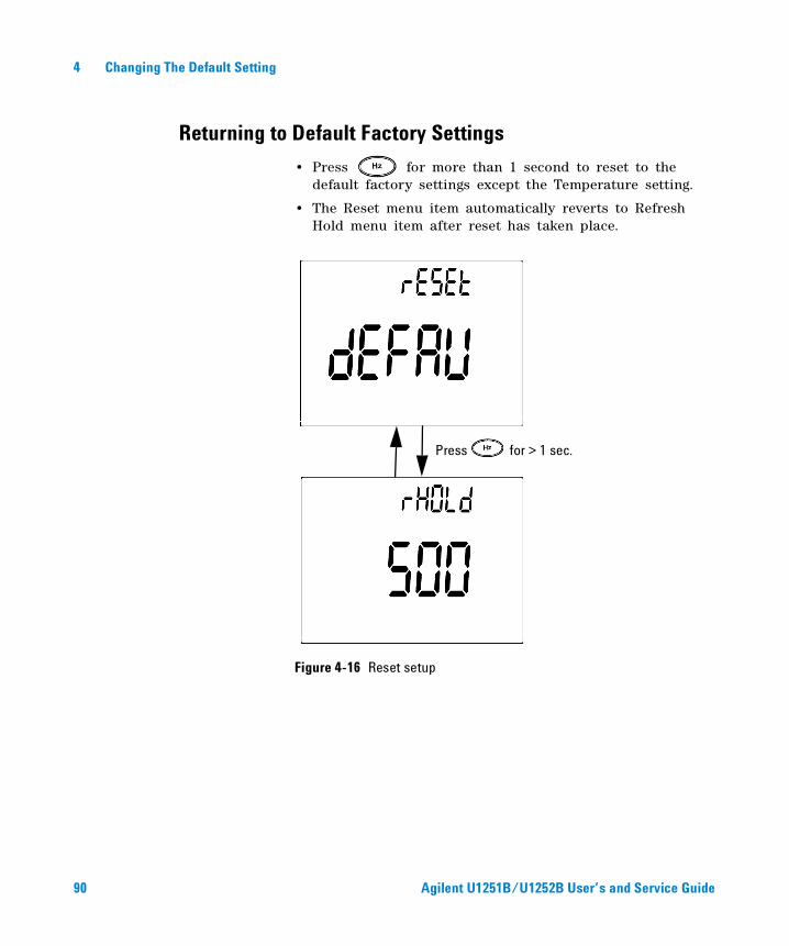
Returning to Default Factory Settings
• Press for more than 1 second to reset to the default factory settings except the Temperature setting.
• The Reset menu item automatically reverts to Refresh Hold menu item after reset has taken place.
Figure 4-16 Reset setup
Press for > 1 sec.
90 Agilent U1251B/U1252B User’s and Service Guide
Changing The Default Setting 4
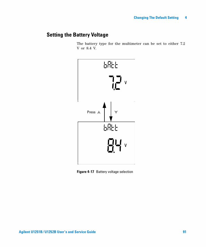
Setting the Battery Voltage
The battery type for the multimeter can be set to either 7.2 V or 8.4 V.
Figure 4-17 Battery voltage selection
Press
Agilent U1251B/U1252B User’s and Service Guide 91
4 Changing The Default Setting
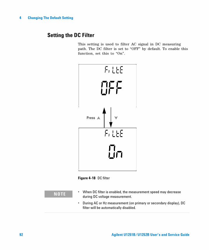
Setting the DC Filter
This setting is used to filter AC signal in DC measuring path. The DC filter is set to “OFF” by default. To enable this function, set this to “On”.
Figure 4-18 DC filter
Press
NOTE • When DC filter is enabled, the measurement speed may decrease during DC voltage measurement.
• During AC or Hz measurement (on primary or secondary display), DC filter will be automatically disabled.
92 Agilent U1251B/U1252B User’s and Service Guide
Agilent U1251B and U1252B Handheld Digital MultimeterUser’s and Service Guide
5 Maintenance
Introduction 94
General Maintenance 94
Replacing the Battery 95
Charging the Battery 97
Replacing the Fuse 103
Troubleshooting 105
This chapter helps you to troubleshoot a failing handheld digital multimeter.
93Agilent Technologies
5 Maintenance
Introduction
Repair or service which is not covered in this manual should
only be performed by a qualified personnel.
General Maintenance
Besides the above hazard, dirt or moisture in the terminals can distort readings. The steps for cleaning are as follows:
1 Turn the meter off and remove the test leads.
2 Turn the meter over and shake out any dirt that may have accumulated in the terminals.
3 Wipe the case with a damp cloth and a mild detergent — do not use abrasives or solvents. Wipe the contacts in each terminal with a clean swab dipped in alcohol.
WARNING Ensure that the terminal connections are correct for that particular measurement before proceeding. To avoid damaging the device, do not exceed the input limit.
94 Agilent U1251B/U1252B User’s and Service Guide
Maintenance 5
Replacing the Battery
The meter is powered by a 7.2 V battery. Use only the specified type. To ensure that the correct battery type is used, replace the battery immediately when the low battery sign flashes. If your meter has the rechargeable battery type, refer to the section “Charging The Battery”. The procedures for battery replacement are listed below:
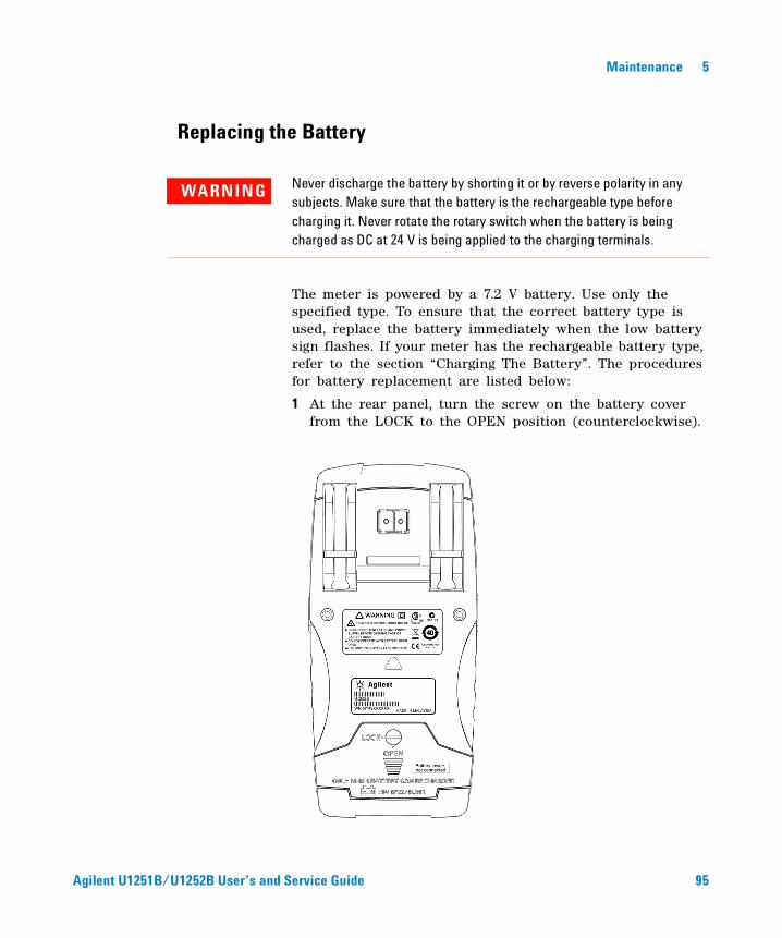
1 At the rear panel, turn the screw on the battery cover from the LOCK to the OPEN position (counterclockwise).
WARNING Never discharge the battery by shorting it or by reverse polarity in any subjects. Make sure that the battery is the rechargeable type before charging it. Never rotate the rotary switch when the battery is being charged as DC at 24 V is being applied to the charging terminals.
Agilent U1251B/U1252B User’s and Service Guide 95
5 Maintenance
2 Slide down the battery cover.
3 Lift the battery cover up.
4 Replace the specified battery.
5 Reverse the above procedures to close the cover.
NOTE List of compatible batteries for the Agilent U1251B :
• 9V Alkaline non-chargeable battery (ANSI/NEDA 1604A or IEC 6LR61)
• 9V Carbon-zinc non-chargeable battery (ANSI/NEDA 1604D or IEC6F22)
List of compatible batteries for the Agilent U1252B :
• 7.2V 300mAH Ni-MH Rechargeable battery, 9V size
• 8.4V 300mAH Ni-MH rechargeable battery, 9V size
• 9V Alkaline non-chargeable battery (ANSI/NEDA 1604A or IEC 6LR61)
• 9V Carbon-zinc non-chargeable battery (ANSI/NEDA 1604D or IEC6F22)
96 Agilent U1251B/U1252B User’s and Service Guide
Maintenance 5
Charging the Battery
This meter is powered by a 7.2 V NiMH rechargeable battery. Use the specified accessory, the 24 V DC adaptor to charge the battery. Remember never to turn the rotary switch of the meter when its battery is being charged. Use the following procedures to charge the battery:
1 Remove and disconnect the test leads from the meter.
2 Turn the rotary switch to the position. Connect the power cord to the DC adapter.
3 Plug the Red (+)/ Black (- ) banana terminals of the DC adapter to the and the “COM” terminals
WARNING Never discharge the battery by shorting it or by reverse polarity in any subjects. Make sure the battery is the rechargeable type before charging it. Never rotate the rotary switch when the battery is being charged as DC at 24 V is being applied to the charging terminals.
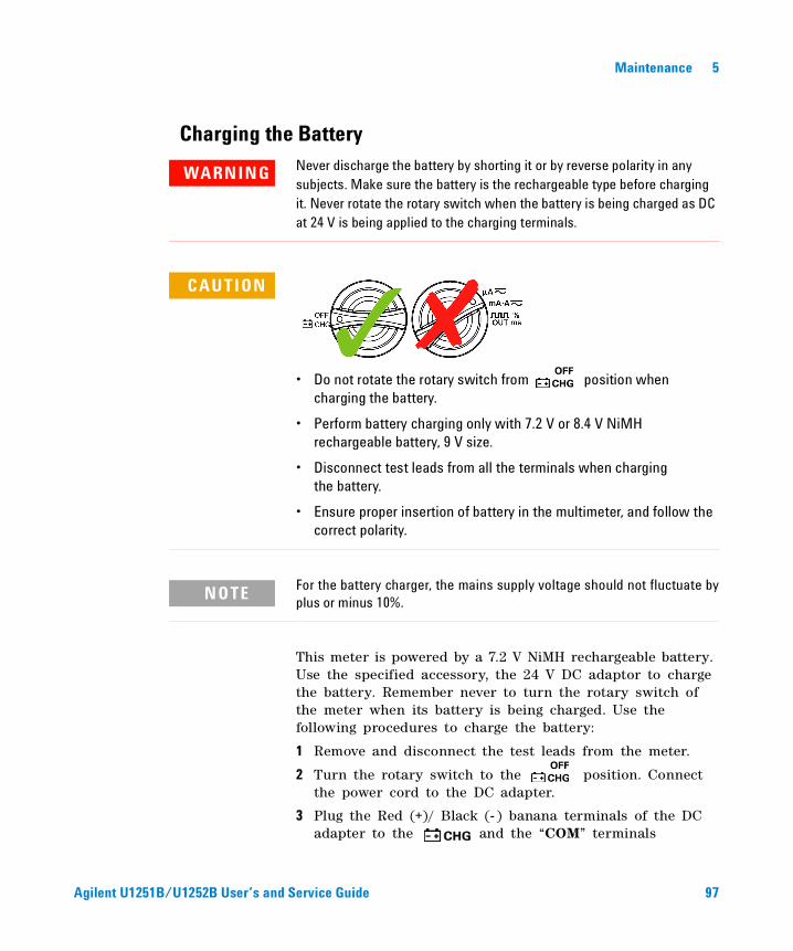
CAUTION
• Do not rotate the rotary switch from position when charging the battery.
• Perform battery charging only with 7.2 V or 8.4 V NiMH rechargeable battery, 9 V size.
• Disconnect test leads from all the terminals when chargingthe battery.
• Ensure proper insertion of battery in the multimeter, and follow the correct polarity.
NOTE For the battery charger, the mains supply voltage should not fluctuate byplus or minus 10%.
Agilent U1251B/U1252B User’s and Service Guide 97
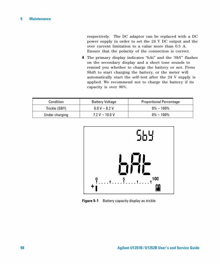
5 Maintenance
respectively. The DC adaptor can be replaced with a DC power supply in order to set the 24 V DC output and the over current limitation to a value more than 0.5 A. Ensure that the polarity of the connection is correct.
4 The primary display indicates “bAt” and the ‘SbY” flashes on the secondary display and a short tone sounds to remind you whether to charge the battery or not. Press Shift to start charging the battery, or the meter will automatically start the self- test after the 24 V supply is applied. We recommend not to charge the battery if its capacity is over 90%.
Figure 5-1 Battery capacity display as trickle
Condition Battery Voltage Proportional Percentage
Trickle (SBY) 6.0 V ~ 8.2 V 0% ~ 100%
Under charging 7.2 V ~ 10.0 V 0% ~ 100%
98 Agilent U1251B/U1252B User’s and Service Guide
Maintenance 5
5 After pressing Shift or when the self- test starts, the meter performs a self- test to check if the battery in the meter is the rechargeable type. The self- test takes about 2 to 3 minutes. Avoid pressing any button during the self- test. A message is diplayed as shown below.
Figure 5-2 Self test
Error Condition Secondary Display
OL
• No battery in the meter
• Battery failing
• Battery is full
Agilent U1251B/U1252B User’s and Service Guide 99
5 Maintenance
Figure 5-3 Error messages
The smart charging mode will start if the meter passes the self- test. The charging time is limited to not more than 220 minutes. The secondary display will count down the charging time. During charging, no buttons can be pressed. The error message may appear during charging to alert any overcharging of the battery.
Error Condition Secondary Display
C-Err
• No rechargeable batteryinside
• Battery failing
NOTE• If the OL message appears while the battery is inside, do not charge the battery.• If the C-Err message appears, check if the battery is the specified type. Use the
battery as specified in this guide. Ensure that the battery is the correct rechargeable type before charging it again. After replacing with the correct rechargeable battery, press Shift to perform the self-test again. If the C-Err message reappears, replace with a new battery,
100 Agilent U1251B/U1252B User’s and Service Guide
Maintenance 5
Figure 5-4 Charging mode
6 The charge end message (C–End) appears on the secondary display once charging is completed. The trickle charging current is provided to maintain the battery capacity. The flashing signs of and appear to show the trickle state.
7 Remove the DC adapter when the C–End message appears on the secondary display. Do not turn the rotary switch before removing the adapter from the terminals.
Figure 5-5 Charge end and trickle state
Agilent U1251B/U1252B User’s and Service Guide 101
5 Maintenance
Figure 5-6 Battery charging procedures
Press to start charge
Error-Full
Error-Empty
Battery can be charged
Fully charged
Error
102 Agilent U1251B/U1252B User’s and Service Guide
Maintenance 5
Replacing the Fuse
Follow the procedures below to replace the fuse.
1 Turn the meter off and disconnect the test leads from the external equipment. Make sure to remove the adaptor.
2 Wear clean/dry gloves and do not touch any other component except the fuse and plastic parts. The current calibration is considered shunt only, so do not recalibrate the meter after replacing the fuse.
3 Remove the battery cover compartment to replace the fuse.
4 Loosen the two screws on the bottom case and remove the cover.
5 Loosen the two screws on the top corners to lift the circuit board.
6 Gently remove the defective fuse by prying one end of the fuse loose and removing it out of the fuse bracket.
7 Replace with a new fuse of the same size and rating. Make sure the new fuse is centered in the fuse holder.
8 Ensure that the rotary switch on the top case and the circuit board switch stay on the OFF position.
9 Then re- fasten the circuit board and the bottom cover.
10 Refer to the table below for the part number, rate and size of the fuses.
NOTE This manual provides only the fuse replacement procedures, but not thefuse replacement markings.
Fuse Agilent Part Number Rating Size Type
1 2110-1400 440mA/1000V 10 mm x 35 mm Fast blow Fuse
2 2110-1402 11A/1000V 10 mm x 38 mm
Agilent U1251B/U1252B User’s and Service Guide 103
5 Maintenance
Figure 5-7 Fuse replacement
Fuse 1
Fuse 2
104 Agilent U1251B/U1252B User’s and Service Guide
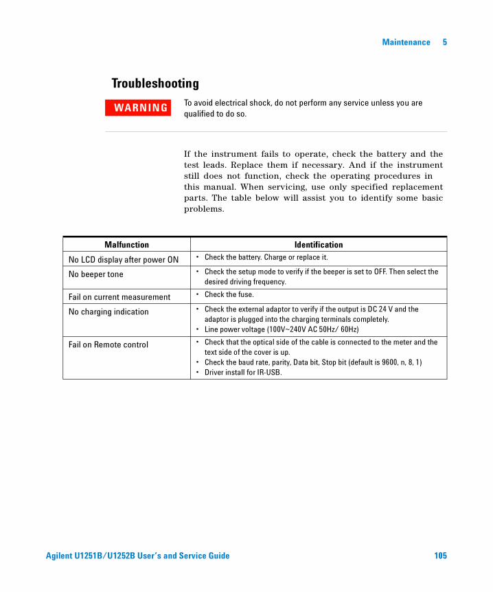
Maintenance 5
Troubleshooting
If the instrument fails to operate, check the battery and the test leads. Replace them if necessary. And if the instrument still does not function, check the operating procedures in this manual. When servicing, use only specified replacement parts. The table below will assist you to identify some basic problems.
WARNING To avoid electrical shock, do not perform any service unless you are qualified to do so.
Malfunction Identification
No LCD display after power ON • Check the battery. Charge or replace it.
No beeper tone • Check the setup mode to verify if the beeper is set to OFF. Then select the desired driving frequency.
Fail on current measurement • Check the fuse.
No charging indication • Check the external adaptor to verify if the output is DC 24 V and the adaptor is plugged into the charging terminals completely.
• Line power voltage (100V~240V AC 50Hz/ 60Hz)
Fail on Remote control • Check that the optical side of the cable is connected to the meter and the text side of the cover is up.
• Check the baud rate, parity, Data bit, Stop bit (default is 9600, n, 8, 1)• Driver install for IR-USB.
Agilent U1251B/U1252B User’s and Service Guide 105

5 Maintenance
106 Agilent U1251B/U1252B User’s and Service Guide
Agilent U1251B and U1252B Handheld Digital MultimeterUser’s and Service Guide
6 Performance Tests and Calibration
Calibration Overview 108
Recommended Test Equipment 110
Basic Operating Test 111
Test Considerations 114
Performance Verification Tests 116
Calibration Security 124
Calibration Process 128
Adjustments Consideration 130
This chapter contains the performance test procedures and the adjustment procedures. The performance test procedures allow you to verify that the handheld digital multimeter is operating within its published specifications.
107Agilent Technologies
6 Performance Tests and Calibration
Calibration Overview
This manual contains procedures to verify the instrument’s performance and adjustment (calibration).
Closed-case Electronic Calibration
This instrument features closed- case electronic calibration. No internal mechanical adjustments are required. The instrument calculates correction factors based upon the input reference value you set. The new correction factors are stored in the non- volatile memory until the next calibration adjustment is performed. The non- volatile EEPROM calibration memory is retained when the power is off.
Agilent Technologies Calibration Services
When your instrument is due for calibration, contact your local Agilent Service Center for a low- cost recalibration.
Calibration Interval
A 1- year interval is adequate for most applications. Accuracy specifications are warranted only if adjustment is made at regular calibration intervals. Accuracy specifications are not warranted beyond the 1- year calibration interval. Agilent does not recommend extending calibration intervals beyond 2 years for any application.
NOTE Make sure you have read the “Test Considerations” on page 114 before calibrating the instrument.
108 Agilent U1251B/U1252B User’s and Service Guide
Performance Tests and Calibration 6
Adjustment is Recommended
Specifications are only guaranteed within the period stated from the last adjustment. Agilent recommends that readjustment should be performed during the calibration process for best performance. This will assure that the U1251B/U1252B will remain within the specifications for the next calibration interval. This criterion for the re- adjustment provides the best long–term stability.
Performance data are measured during the Performance Verification Tests but this does not guarantee that the instrument will remain within these limits unless the adjustments are performed.
Refer to the section “To Read the Calibration Count” on page 139 and verify that all the adjustments have been performed.
Agilent U1251B/U1252B User’s and Service Guide 109
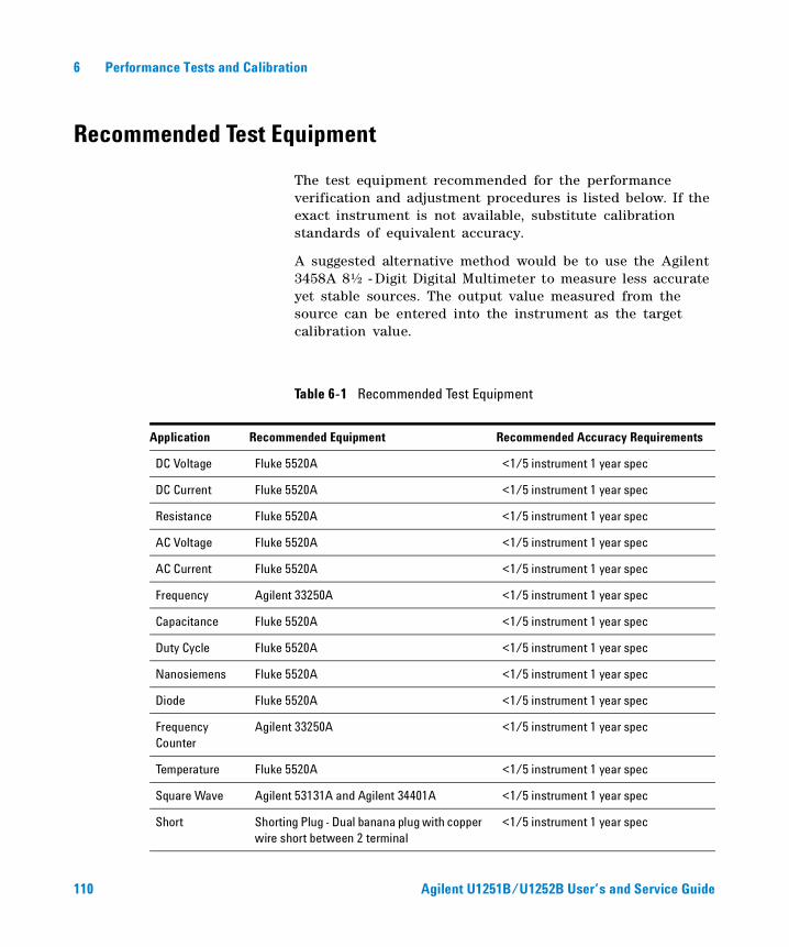
6 Performance Tests and Calibration
Recommended Test Equipment
The test equipment recommended for the performance verification and adjustment procedures is listed below. If the exact instrument is not available, substitute calibration standards of equivalent accuracy.
A suggested alternative method would be to use the Agilent 3458A 8½ - Digit Digital Multimeter to measure less accurate yet stable sources. The output value measured from the source can be entered into the instrument as the target calibration value.
Table 6-1 Recommended Test Equipment
Application Recommended Equipment Recommended Accuracy Requirements
DC Voltage Fluke 5520A <1/5 instrument 1 year spec
DC Current Fluke 5520A <1/5 instrument 1 year spec
Resistance Fluke 5520A <1/5 instrument 1 year spec
AC Voltage Fluke 5520A <1/5 instrument 1 year spec
AC Current Fluke 5520A <1/5 instrument 1 year spec
Frequency Agilent 33250A <1/5 instrument 1 year spec
Capacitance Fluke 5520A <1/5 instrument 1 year spec
Duty Cycle Fluke 5520A <1/5 instrument 1 year spec
Nanosiemens Fluke 5520A <1/5 instrument 1 year spec
Diode Fluke 5520A <1/5 instrument 1 year spec
Frequency Counter
Agilent 33250A <1/5 instrument 1 year spec
Temperature Fluke 5520A <1/5 instrument 1 year spec
Square Wave Agilent 53131A and Agilent 34401A <1/5 instrument 1 year spec
Short Shorting Plug - Dual banana plug with copper wire short between 2 terminal
<1/5 instrument 1 year spec
110 Agilent U1251B/U1252B User’s and Service Guide
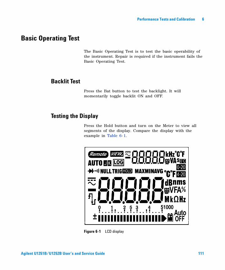
Performance Tests and Calibration 6
Basic Operating Test
The Basic Operating Test is to test the basic operability of the instrument. Repair is required if the instrument fails the Basic Operating Test.
Backlit Test
Press the Bat button to test the backlight. It will momentarily toggle backlit ON and OFF.
Testing the Display
Press the Hold button and turn on the Meter to view all segments of the display. Compare the display with the example in Table 6- 1.
Figure 6-1 LCD display
Agilent U1251B/U1252B User’s and Service Guide 111
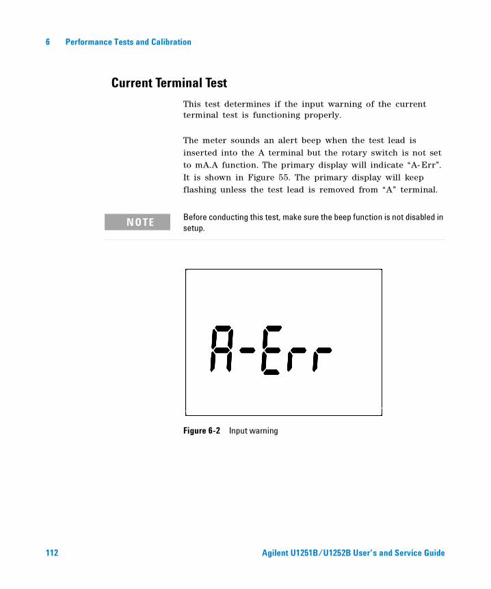
6 Performance Tests and Calibration
Current Terminal Test
This test determines if the input warning of the current terminal test is functioning properly.
The meter sounds an alert beep when the test lead is inserted into the A terminal but the rotary switch is not set to mA.A function. The primary display will indicate “A- Err”. It is shown in Figure 55. The primary display will keep flashing unless the test lead is removed from “A” terminal.
Figure 6-2 Input warning
NOTE Before conducting this test, make sure the beep function is not disabled in setup.
112 Agilent U1251B/U1252B User’s and Service Guide
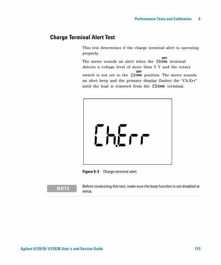
Performance Tests and Calibration 6
Charge Terminal Alert Test
This test determines if the charge terminal alert is operating properly.
The meter sounds an alert when the terminal detects a voltage level of more than 5 V and the rotary
switch is not set to the position. The meter sounds an alert beep and the primary display flashes the “Ch.Err” until the lead is removed from the terminal.
Figure 6-3 Charge terminal alert
NOTE Before conducting this test, make sure the beep function is not disabled at setup.
Agilent U1251B/U1252B User’s and Service Guide 113
6 Performance Tests and Calibration
Test Considerations
Long test leads can also act as antennas which may pick up AC signals.
For optimum performance, all procedures should comply with the following recommendations:
• Ensure that the calibration ambient temperature is stable and is between 18 °C and 28 °C. Ideally the calibration should be performed at 23 °C ± 1 °C.
• Ensure that the ambient relative humidity is less than 80%.
• Allow a warm- up period of five minutes with a Shorting Plug connected to the V and COM input terminals.
• Use shielded twisted pair Teflon- insulated cables to reduce settling and noise errors. Keep the input cables as short as possible.
• Connect the input cable shields to earth ground. Except where noted in the procedures, connect the calibrator LO source to earth ground at the calibrator. It is important that the LO to earth ground connection be made at only one place in the circuit to avoid ground loops.
Please ensure that the calibration standards and test procedures used do not introduce additional errors. Ideally, the standards used to verify and adjust the instrument should be of an order of magnitude more accurate than each instrument range full- scale error specification.
For the DC voltage, DC current, and resistance gain verification measurements, ensure that the calibrator's "0" output is correct. You will need to set the offset for each range of the measuring function being verified.
114 Agilent U1251B/U1252B User’s and Service Guide
Performance Tests and Calibration 6
Input Connections
Test connections to the instrument are best accomplished using the dual banana plug with copper wire short between the two terminals for low- thermal offset measurement. We recommend the use of shielded, twisted- pair, Teflon interconnect cables of minimum length between the calibrator and the multimeter. The cable shields should be earth ground referenced. This configuration is recommended to attain optimal noises and settling time performance during calibration.
Agilent U1251B/U1252B User’s and Service Guide 115
6 Performance Tests and Calibration
Performance Verification Tests
Use the Performance Verification Tests to verify the easurement performance of the instrument. The performance verification tests use the instrument’s specifications listed in the U1251B/U1252B Data Sheet.
The performance verification tests are recommended as acceptance tests when you first receive the instrument. The acceptance test results should be compared against the one year test limits. After acceptance, you should repeat the performance verification tests at every calibration interval.
If the multimeter fails the performance verification tests, adjustment or repair is required.
NOTE Make sure you have read the “Test Considerations” on page 114 before doing the performance verification tests.
116 Agilent U1251B/U1252B User’s and Service Guide
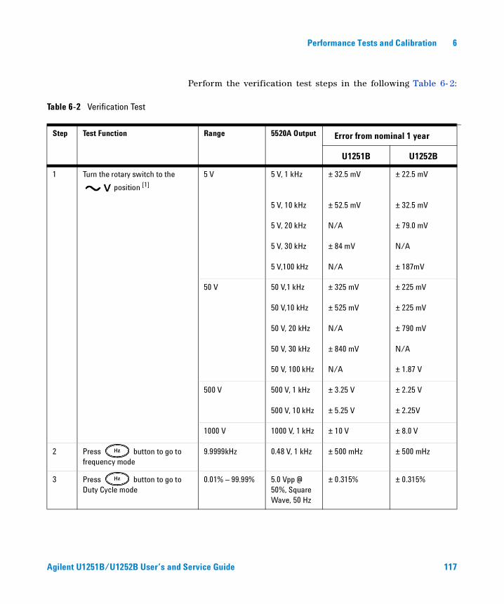
Performance Tests and Calibration 6
Perform the verification test steps in the following Table 6- 2:
Table 6-2 Verification Test
Step Test Function Range 5520A Output Error from nominal 1 year
U1251B U1252B
1 Turn the rotary switch to the
position [1]
5 V 5 V, 1 kHz ± 32.5 mV ± 22.5 mV
5 V, 10 kHz ± 52.5 mV ± 32.5 mV
5 V, 20 kHz N/A ± 79.0 mV
5 V, 30 kHz ± 84 mV N/A
5 V,100 kHz N/A ± 187mV
50 V 50 V,1 kHz ± 325 mV ± 225 mV
50 V,10 kHz ± 525 mV ± 225 mV
50 V, 20 kHz N/A ± 790 mV
50 V, 30 kHz ± 840 mV N/A
50 V, 100 kHz N/A ± 1.87 V
500 V 500 V, 1 kHz ± 3.25 V ± 2.25 V
500 V, 10 kHz ± 5.25 V ± 2.25V
1000 V 1000 V, 1 kHz ± 10 V ± 8.0 V
2 Press button to go to frequency mode
9.9999kHz 0.48 V, 1 kHz ± 500 mHz ± 500 mHz
3 Press button to go to Duty Cycle mode
0.01% – 99.99% 5.0 Vpp @ 50%, Square Wave, 50 Hz
± 0.315% ± 0.315%
Agilent U1251B/U1252B User’s and Service Guide 117
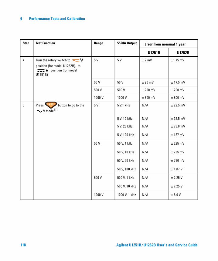
118 Agilent U1251B/U1252B User’s and Service Guide
6 Performance Tests and Calibration
Step Test Function Range 5520A Output Error from nominal 1 year
U1251B U1252B
4 Turn the rotary switch to
position (for model U1252B), to position (for model
U1251B)
5 V 5 V ± 2 mV ±1.75 mV
50 V 50 V ± 20 mV ± 17.5 mV
500 V 500 V ± 200 mV ± 200 mV
1000 V 1000 V ± 800 mV ± 800 mV
5 Press button to go to the
V mode [1]
5 V 5 V,1 kHz N/A ± 22.5 mV
5 V, 10 kHz N/A ± 32.5 mV
5 V, 20 kHz N/A ± 79.0 mV
5 V, 100 kHz N/A ± 187 mV
50 V 50 V, 1 kHz N/A ± 225 mV
50 V, 10 kHz N/A ± 225 mV
50 V, 20 kHz N/A ± 790 mV
50 V, 100 kHz N/A ± 1.87 V
500 V 500 V, 1 kHz N/A ± 2.25 V
500 V, 10 kHz N/A ± 2.25 V
1000 V 1000 V, 1 kHz N/A ± 8.0 V
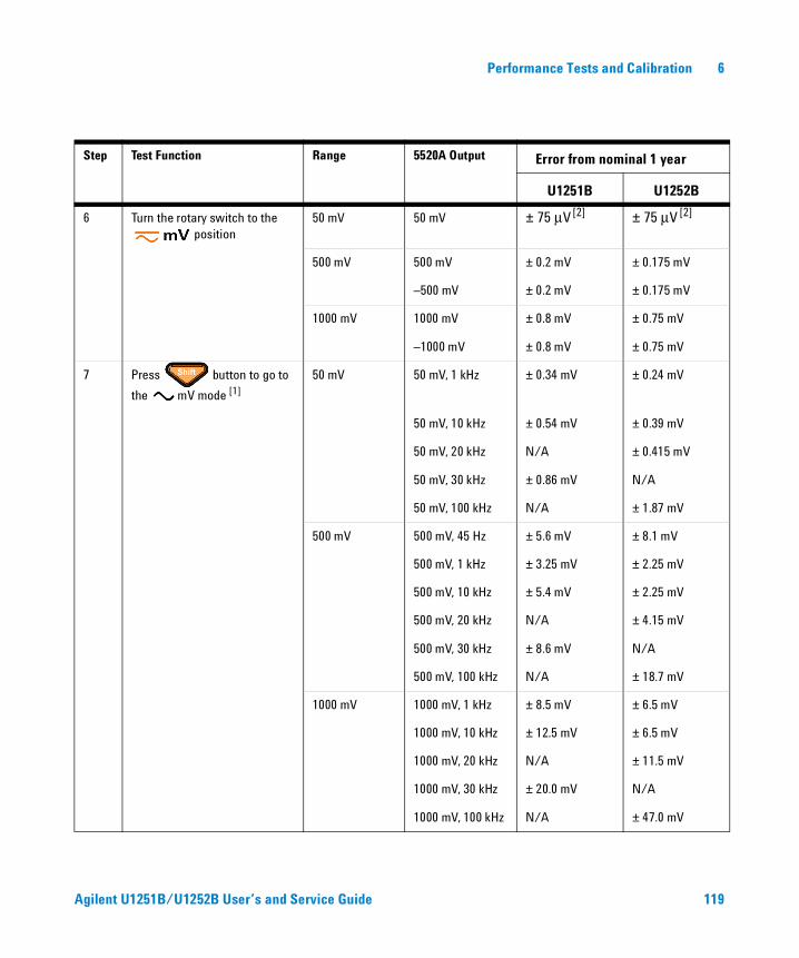
Performance Tests and Calibration 6
Agilent U1251B/U1252B User’s and Service Guide 119
Step Test Function Range 5520A Output Error from nominal 1 year
U1251B U1252B
6 Turn the rotary switch to the position
50 mV 50 mV ± 75 μV [2] ± 75 μV [2]
500 mV 500 mV ± 0.2 mV ± 0.175 mV
–500 mV ± 0.2 mV ± 0.175 mV
1000 mV 1000 mV ± 0.8 mV ± 0.75 mV
–1000 mV ± 0.8 mV ± 0.75 mV
7 Press button to go to
the mV mode [1]
50 mV 50 mV, 1 kHz ± 0.34 mV ± 0.24 mV
50 mV, 10 kHz ± 0.54 mV ± 0.39 mV
50 mV, 20 kHz N/A ± 0.415 mV
50 mV, 30 kHz ± 0.86 mV N/A
50 mV, 100 kHz N/A ± 1.87 mV
500 mV 500 mV, 45 Hz ± 5.6 mV ± 8.1 mV
500 mV, 1 kHz ± 3.25 mV ± 2.25 mV
500 mV, 10 kHz ± 5.4 mV ± 2.25 mV
500 mV, 20 kHz N/A ± 4.15 mV
500 mV, 30 kHz ± 8.6 mV N/A
500 mV, 100 kHz N/A ± 18.7 mV
1000 mV 1000 mV, 1 kHz ± 8.5 mV ± 6.5 mV
1000 mV, 10 kHz ± 12.5 mV ± 6.5 mV
1000 mV, 20 kHz N/A ± 11.5 mV
1000 mV, 30 kHz ± 20.0 mV N/A
1000 mV, 100 kHz N/A ± 47.0 mV
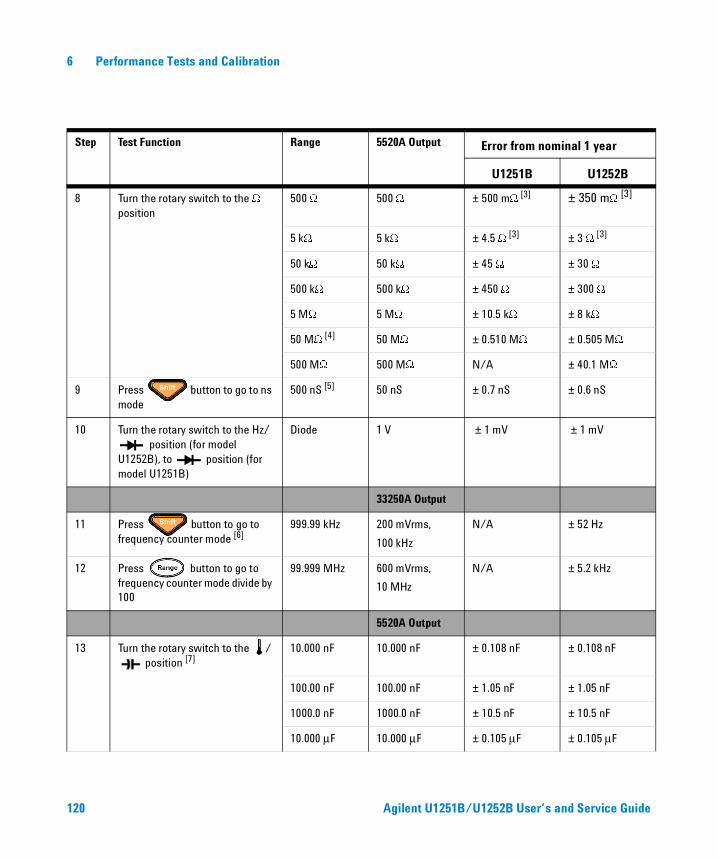
6 Performance Tests and Calibration
Step Test Function Range 5520A Output Error from nominal 1 year
U1251B U1252B
8 Turn the rotary switch to the W position
500 W 500 W ± 500 mW [3] ± 350 mW [3]
5 kW 5 kW ± 4.5 W [3] ± 3 W [3]
50 kW 50 kW ± 45 W ± 30 W
500 kW 500 kW ± 450 W ± 300 W
5 MW 5 MW ± 10.5 kW ± 8 kW
50 MW [4] 50 MW ± 0.510 MW ± 0.505 MW
500 MW 500 MW N/A ± 40.1 MW
9 Press button to go to ns mode
500 nS [5] 50 nS ± 0.7 nS ± 0.6 nS
10 Turn the rotary switch to the Hz/ position (for model
U1252B), to position (for model U1251B)
Diode 1 V ± 1 mV ± 1 mV
33250A Output
11 Press button to go to frequency counter mode [6]
999.99 kHz 200 mVrms,
100 kHz
N/A ± 52 Hz
12 Press button to go to frequency counter mode divide by 100
99.999 MHz 600 mVrms,
10 MHz
N/A ± 5.2 kHz
5520A Output
13 Turn the rotary switch to the / position [7]
10.000 nF 10.000 nF ± 0.108 nF ± 0.108 nF
100.00 nF 100.00 nF ± 1.05 nF ± 1.05 nF
1000.0 nF 1000.0 nF ± 10.5 nF ± 10.5 nF
10.000 μF 10.000 μF ± 0.105 μF ± 0.105 μF
120 Agilent U1251B/U1252B User’s and Service Guide
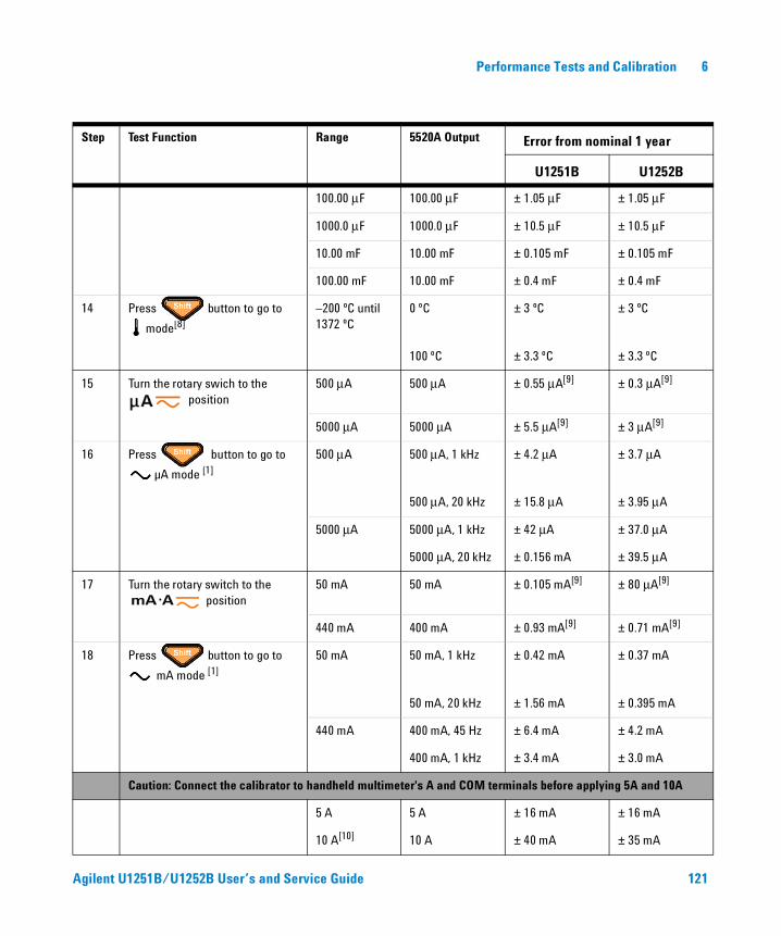
Performance Tests and Calibration 6
Step Test Function Range 5520A Output Error from nominal 1 year
U1251B U1252B
100.00 μF 100.00 μF ± 1.05 μF ± 1.05 μF
1000.0 μF 1000.0 μF ± 10.5 μF ± 10.5 μF
10.00 mF 10.00 mF ± 0.105 mF ± 0.105 mF
100.00 mF 10.00 mF ± 0.4 mF ± 0.4 mF
14 Press button to go to
mode[8]
–200 ºC until 1372 ºC
0 ºC ± 3 ºC ± 3 ºC
100 ºC ± 3.3 ºC ± 3.3 ºC
15 Turn the rotary swich to the position
500 μA 500 μA ± 0.55 μA[9] ± 0.3 μA[9]
5000 μA 5000 μA ± 5.5 μA[9] ± 3 μA[9]
16 Press button to go to
µA mode [1]
500 μA 500 μA, 1 kHz ± 4.2 μA ± 3.7 μA
500 μA, 20 kHz ± 15.8 μA ± 3.95 μA
5000 μA 5000 μA, 1 kHz ± 42 μA ± 37.0 μA
5000 μA, 20 kHz ± 0.156 mA ± 39.5 μA
17 Turn the rotary switch to the position
50 mA 50 mA ± 0.105 mA[9] ± 80 μA[9]
440 mA 400 mA ± 0.93 mA[9] ± 0.71 mA[9]
18 Press button to go to
mA mode [1]
50 mA 50 mA, 1 kHz ± 0.42 mA ± 0.37 mA
50 mA, 20 kHz ± 1.56 mA ± 0.395 mA
440 mA 400 mA, 45 Hz ± 6.4 mA ± 4.2 mA
400 mA, 1 kHz ± 3.4 mA ± 3.0 mA
Caution: Connect the calibrator to handheld multimeter's A and COM terminals before applying 5A and 10A
5 A 5 A ± 16 mA ± 16 mA
10 A[10] 10 A ± 40 mA ± 35 mA
Agilent U1251B/U1252B User’s and Service Guide 121
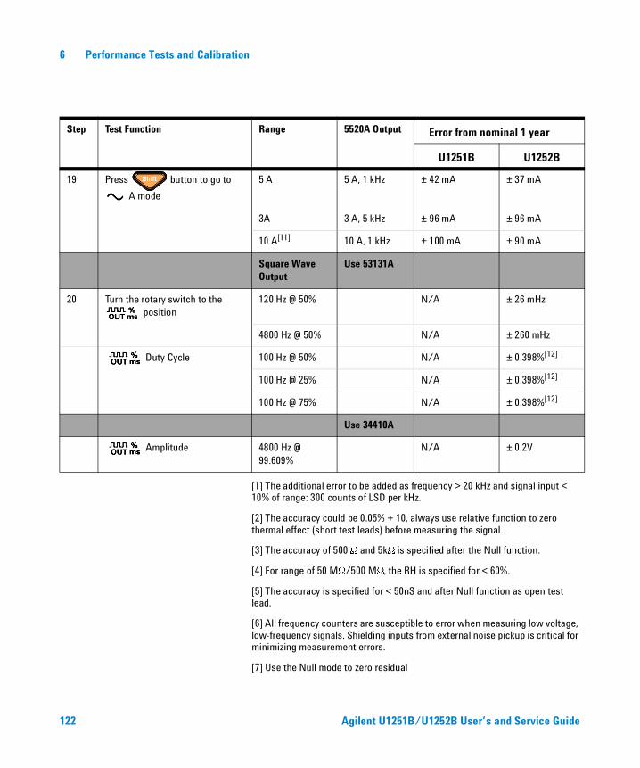
6 Performance Tests and Calibration
[1] The additional error to be added as frequency > 20 kHz and signal input < 10% of range: 300 counts of LSD per kHz.
[2] The accuracy could be 0.05% + 10, always use relative function to zero thermal effect (short test leads) before measuring the signal.
[3] The accuracy of 500 W and 5kW is specified after the Null function.
[4] For range of 50 MW/500 MW, the RH is specified for < 60%.
[5] The accuracy is specified for < 50nS and after Null function as open test lead.
[6] All frequency counters are susceptible to error when measuring low voltage, low-frequency signals. Shielding inputs from external noise pickup is critical for minimizing measurement errors.
[7] Use the Null mode to zero residual
Step Test Function Range 5520A Output Error from nominal 1 year
U1251B U1252B
19 Press button to go to
A mode
5 A 5 A, 1 kHz ± 42 mA ± 37 mA
3A 3 A, 5 kHz ± 96 mA ± 96 mA
10 A[11] 10 A, 1 kHz ± 100 mA ± 90 mA
Square Wave Output
Use 53131A
20 Turn the rotary switch to the position
120 Hz @ 50% N/A ± 26 mHz
4800 Hz @ 50% N/A ± 260 mHz
Duty Cycle 100 Hz @ 50% N/A ± 0.398%[12]
100 Hz @ 25% N/A ± 0.398%[12]
100 Hz @ 75% N/A ± 0.398%[12]
Use 34410A
Amplitude 4800 Hz @ 99.609%
N/A ± 0.2V
122 Agilent U1251B/U1252B User’s and Service Guide
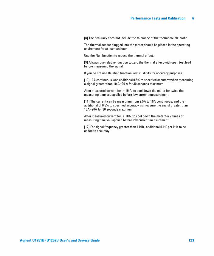
Performance Tests and Calibration 6
[8] The accuracy does not include the tolerance of the thermocouple probe.
The thermal sensor plugged into the meter should be placed in the operating enviroment for at least an hour.
Use the Null function to reduce the thermal effect.
[9] Always use relative function to zero the thermal effect with open test lead before measuring the signal.
If you do not use Relation function, add 20 digits for accuracy purposes.
[10] 10A continuous, and additional 0.5% to specified accuracy when measuring a signal greater than 10 A~20 A for 30 seconds maximum.
After measured current for > 10 A, to cool down the meter for twice the measuring time you applied before low current measurement.
[11] The current can be measuring from 2.5A to 10A continuous, and the additional of 0.5% to specified accuracy as measure the signal greater than 10A~20A for 30 seconds maximum.
After measured current for > 10A, to cool down the meter for 2 times of measuring time you applied before low current measurement
[12] For signal frequency greater than 1 kHz, additional 0.1% per kHz to be added to accuracy
Agilent U1251B/U1252B User’s and Service Guide 123
6 Performance Tests and Calibration
Calibration Security
The calibration security code prevents accidental or unauthorized adjustments to the instrument. When you first receive your instrument, it is secured. Before you can adjust the instrument, you must unsecure it by entering the correct security code (see “Unsecuring the Instrument for Calibration” on page 125).
The security code is set to 1234 when the instrument is shipped from the factory. This code is stored in non- volatile memory, and does not change when power is turned off .
The security code may contain up to 4 numeric characters.
NOTE You can unsecure the instrument from the front panel. The security code can only be changed from the front panel and from the remote interface after the instrument has been unsecured.
NOTE See “To Unsecure the Instrument Without the Security Code” on page 127 if you forget your security code.
124 Agilent U1251B/U1252B User’s and Service Guide
Performance Tests and Calibration 6
Unsecuring the Instrument for Calibration
Before you can adjust the instrument, you must unsecure it by entering the correct security code. The security code is set to 1234 when the instrument is shipped from the factory. The security code is stored in non- volatile memory, and does not change when power is off.
To Unsecure the Instrument from the Front Panel
1 Turn the rotary switch to .
2 Press and button simultaneously to enter the Calibration Security Code entry mode.
3 The primary display shows 5555 and the secondary display show SECUr.
4 Use the editing keys and to step each character in the code.
Use the and to select each character.
5 Press (Save) when done.
6 If the correct security code is entered, the secondary display will show PASS.
Agilent U1251B/U1252B User’s and Service Guide 125
6 Performance Tests and Calibration
To Change the Instrument Calibration Security Code from the Front Panel
1 When the multimeter is in the unsecured mode, press for more than 1 second to enter the Calibration
Security Code setting mode.
2 The factory default calibration security code 1234 will be displayed on the primary display.
3 Use the editing keys and to step each character in the code.
4 Use the and to change each character in the code.
5 Press (Save) to store the new calibration security code.
6 If the new calibration security code has been successfully stored, the secondary display will show PASS.
126 Agilent U1251B/U1252B User’s and Service Guide
Performance Tests and Calibration 6
To Unsecure the Instrument Without the Security Code
To unsecure the instrument without the correct security code, follow the steps below.
1 Record the last 4 digits of the multimeter’s serial number.
2 Turn the rotary switch to .
3 Press and simultaneously to enter the Calibration Security Code entry mode.
The primary display shows 5555 and the secondary display shows SECUr.
4 Press for more than 1 second to enter the Set Default Security Code mode. The secondary display shows SEr.no and the primary display shows 5555.
5 Use the editing keys and to step each character in the code.
6 Use and to select each character.
7 Set the code, same as the last 4 digits of the instrument’s serial number.
8 Press (Save) to confirm the entry.
9 If the 4 digits entered are correct, the secondary display will show PASS.
NOTE If you do not have a record of the security code, you can try 1234 (the fac-tory default code) using the front panel or the remote interface.
Agilent U1251B/U1252B User’s and Service Guide 127
6 Performance Tests and Calibration
Now you can use 1234 as the security code. If you want to enter a new security code, see “To Change the Instrument Calibration Security Code from the Front Panel” on page 126. Make sure you record the new security code.
Calibration Process
To complete a full instrument calibration use following general procedures:
1 Read “Test Considerations” on page 114.
2 Perform the verification tests to characterize the instrument (incoming data).
3 Unsecure the instrument for calibration (see “Calibration Security” on page 124).
4 Perform the adjustment procedures (see “Adjustments Consideration” on page 130).
5 Secure the instrument against calibration.
6 Note the new security code and calibration count in the instrument's maintenance records.
NOTE Make sure to quit the Adjustment Mode before turning off the instrument.
128 Agilent U1251B/U1252B User’s and Service Guide
Performance Tests and Calibration 6
Using the Front Panel for Adjustments
This section describes the procedures to perform adjustments from the front panel.
Selecting the Adjustment Mode
To unsecure the instrument, see “Unsecuring the Instrument for Calibration” on page 125 or “To Unsecure the Instrument Without the Security Code” on page 127. Once unsecured, the reference value will be indicated on the primary display.
Entering Adjustment Values
Use the following adjustment procedure to enter an input calibration value from the front panel:
1 Use the edit keys and to select each digit in the primary display.
2 Use the and the arrow keys to advance through the digits 0 through 9.
3 Press when done to start calibration.
Agilent U1251B/U1252B User’s and Service Guide 129
6 Performance Tests and Calibration
Adjustments Consideration
You will need a test input cable, a connectors set, and a Shorting Plug to adjust the instrument (see “Input Connections” on page 115).
Adjustments for each function should be performed only in the order shown below.
1 Allow the instrument to warm up and stabilize for 5 minutes before performing the adjustments.
2 Ensure that during the adjustments, the low battery indicator does not appear. Replace the batteries as soon as possible to avoid false reading.
3 Consider the thermal effects as you are connecting test leads to the calibrator and handheld multimeter. It is recommended to wait for one minute before you begin the calibration after connecting the test leads.
4 During ambient temperature adjustment, be sure to turn on the instrument for at least 1 hour with the K- type thermocouple connected between the instrument and the calibration source.
NOTE After each adjustment, the secondary display briefly shows PASS. If the calibration fails, the handheld multimeter sounds a beep, and an error number is shown in the secondary display. Calibration error messages are described on page 140. In the event of a calibration failure, correct the problem and repeat the procedure.
CAUTION Never turn off the instrument during an adjustment. This may delete the calibration memory for the present function.
130 Agilent U1251B/U1252B User’s and Service Guide
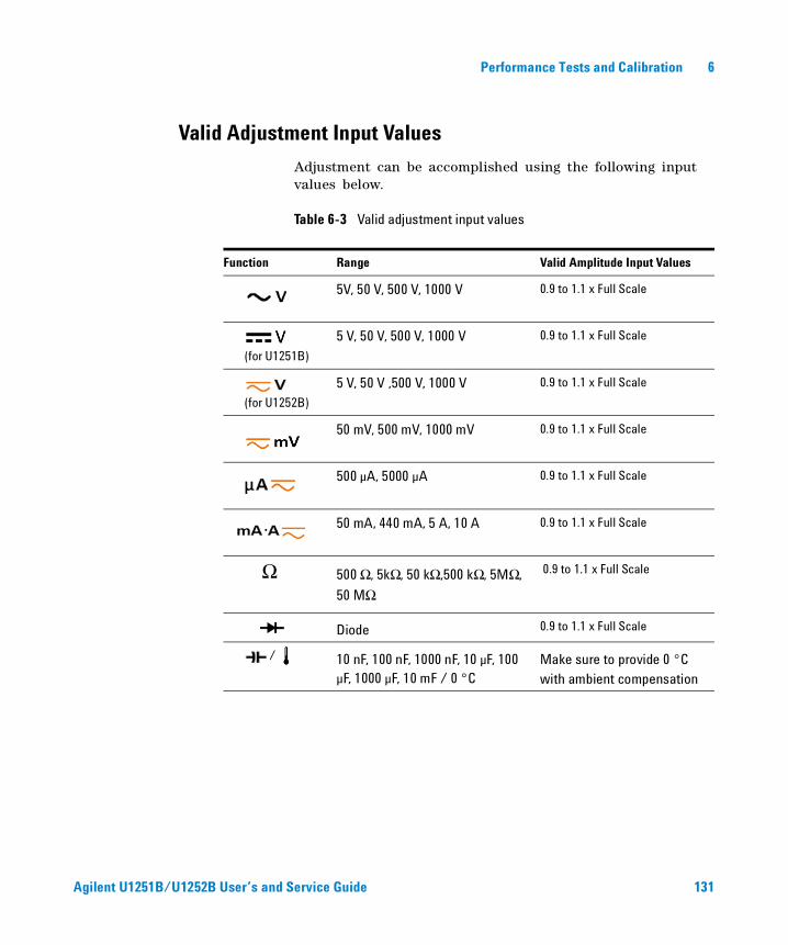
Performance Tests and Calibration 6
Valid Adjustment Input Values
Adjustment can be accomplished using the following input values below.
Table 6-3 Valid adjustment input values
Function Range Valid Amplitude Input Values
5V, 50 V, 500 V, 1000 V 0.9 to 1.1 x Full Scale
(for U1251B)
5 V, 50 V, 500 V, 1000 V 0.9 to 1.1 x Full Scale
(for U1252B)
5 V, 50 V ,500 V, 1000 V 0.9 to 1.1 x Full Scale
50 mV, 500 mV, 1000 mV 0.9 to 1.1 x Full Scale
500 µA, 5000 µA 0.9 to 1.1 x Full Scale
50 mA, 440 mA, 5 A, 10 A 0.9 to 1.1 x Full Scale
Ω 500 Ω, 5kΩ, 50 kΩ,500 kΩ, 5MΩ,
50 MΩ
0.9 to 1.1 x Full Scale
Diode 0.9 to 1.1 x Full Scale
/ 10 nF, 100 nF, 1000 nF, 10 µF, 100 µF, 1000 µF, 10 mF / 0 °C
Make sure to provide 0 °C with ambient compensation
Agilent U1251B/U1252B User’s and Service Guide 131
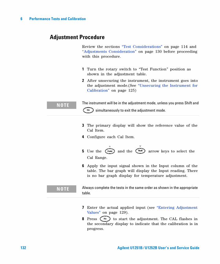
6 Performance Tests and Calibration
Adjustment Procedure
Review the sections “Test Considerations” on page 114 and “Adjustments Consideration” on page 130 before proceeding with this procedure.
1 Turn the rotary switch to “Test Function” position as shown in the adjustment table.
2 After unsecuring the instrument, the instrument goes into the adjustment mode.(See “Unsecuring the Instrument for Calibration” on page 125)
3 The primary display will show the reference value of the Cal Item.
4 Configure each Cal Item.
5 Use the and the arrow keys to select the
Cal Range.
6 Apply the input signal shown in the Input column of the table. The bar graph will display the Input reading. There is no bar graph display for temperature adjustment.
7 Enter the actual applied input (see “Entering Adjustment Values” on page 129).
8 Press to start the adjustment. The CAL flashes in the secondary display to indicate that the calibration is in progress.
NOTE The instrument will be in the adjustment mode, unless you press Shift and
simultaneously to exit the adjustment mode.
NOTE Always complete the tests in the same order as shown in the appropriate table.
132 Agilent U1251B/U1252B User’s and Service Guide
Performance Tests and Calibration 6
For an adjustment that is successful, the secondary display will briefly show PASS. An adjustment failure is indicated by a long beep and a calibration error number appears in the secondary display. The primary display remains at the current Cal Item. Check the input value, range, function, and entered adjustment value to fix the problem. Repeat the adjustment procedure.
9 Repeat steps 1 through 8 for each adjustment point.
10 Verify the adjustments using the “Performance Verification Tests” on page 116. Verify the adjustments using Table 6- 4:
Agilent U1251B/U1252B User’s and Service Guide 133
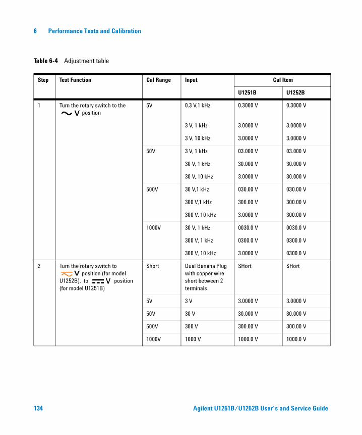
134 Agilent U1251B/U1252B User’s and Service Guide
6 Performance Tests and Calibration
Table 6-4 Adjustment table
Step Test Function Cal Range Input Cal Item
U1251B U1252B
1 Turn the rotary switch to the position
5V 0.3 V,1 kHz 0.3000 V 0.3000 V
3 V, 1 kHz 3.0000 V 3.0000 V
3 V, 10 kHz 3.0000 V 3.0000 V
50V 3 V, 1 kHz 03.000 V 03.000 V
30 V, 1 kHz 30.000 V 30.000 V
30 V, 10 kHz 3.0000 V 30.000 V
500V 30 V,1 kHz 030.00 V 030.00 V
300 V,1 kHz 300.00 V 300.00 V
300 V, 10 kHz 3.0000 V 300.00 V
1000V 30 V, 1 kHz 0030.0 V 0030.0 V
300 V, 1 kHz 0300.0 V 0300.0 V
300 V, 10 kHz 3.0000 V 0300.0 V
2 Turn the rotary switch to position (for model
U1252B), to position (for model U1251B)
Short Dual Banana Plug with copper wire short between 2 terminals
SHort SHort
5V 3 V 3.0000 V 3.0000 V
50V 30 V 30.000 V 30.000 V
500V 300 V 300.00 V 300.00 V
1000V 1000 V 1000.0 V 1000.0 V
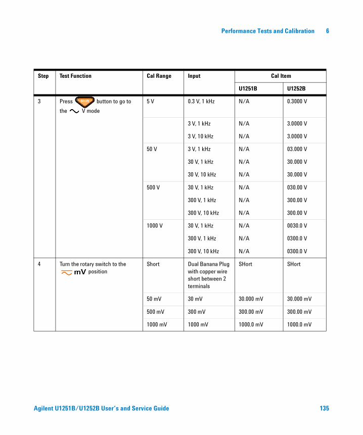
Performance Tests and Calibration 6
Step Test Function Cal Range Input Cal Item
U1251B U1252B
3 Press button to go to
the V mode
5 V 0.3 V, 1 kHz N/A 0.3000 V
3 V, 1 kHz N/A 3.0000 V
3 V, 10 kHz N/A 3.0000 V
50 V 3 V, 1 kHz N/A 03.000 V
30 V, 1 kHz N/A 30.000 V
30 V, 10 kHz N/A 30.000 V
500 V 30 V, 1 kHz N/A 030.00 V
300 V, 1 kHz N/A 300.00 V
300 V, 10 kHz N/A 300.00 V
1000 V 30 V, 1 kHz N/A 0030.0 V
300 V, 1 kHz N/A 0300.0 V
300 V, 10 kHz N/A 0300.0 V
4 Turn the rotary switch to the position
Short Dual Banana Plug with copper wire short between 2 terminals
SHort SHort
50 mV 30 mV 30.000 mV 30.000 mV
500 mV 300 mV 300.00 mV 300.00 mV
1000 mV 1000 mV 1000.0 mV 1000.0 mV
Agilent U1251B/U1252B User’s and Service Guide 135
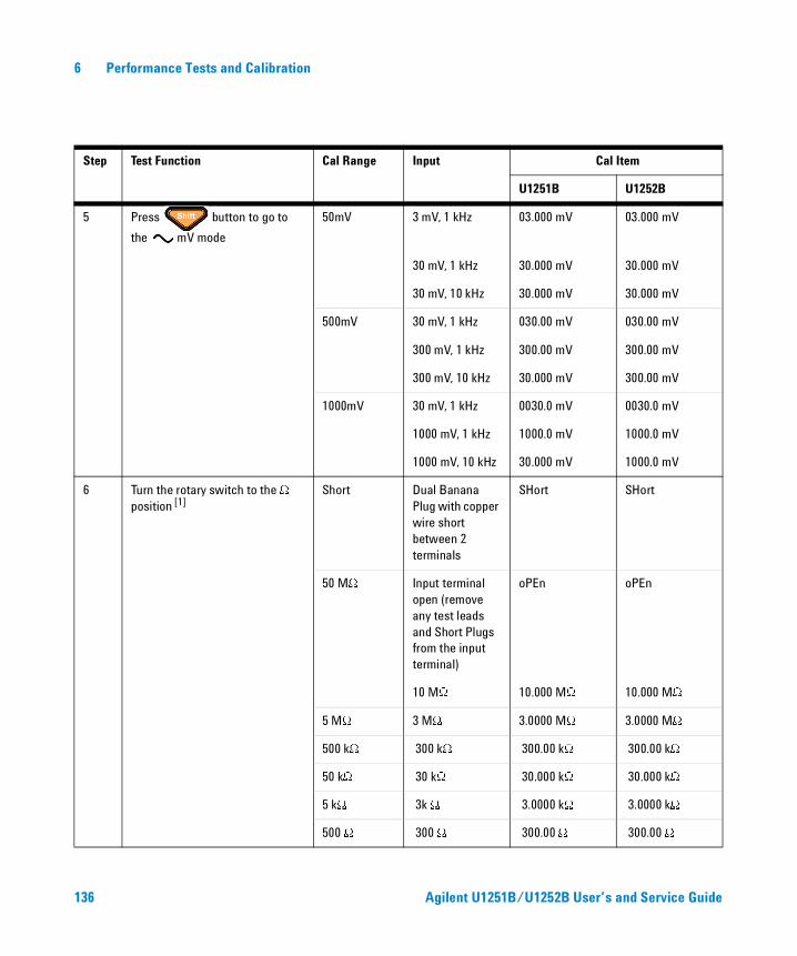
6 Performance Tests and Calibration
Step Test Function Cal Range Input Cal Item
U1251B U1252B
5 Press button to go to
the mV mode
50mV 3 mV, 1 kHz 03.000 mV 03.000 mV
30 mV, 1 kHz 30.000 mV 30.000 mV
30 mV, 10 kHz 30.000 mV 30.000 mV
500mV 30 mV, 1 kHz 030.00 mV 030.00 mV
300 mV, 1 kHz 300.00 mV 300.00 mV
300 mV, 10 kHz 30.000 mV 300.00 mV
1000mV 30 mV, 1 kHz 0030.0 mV 0030.0 mV
1000 mV, 1 kHz 1000.0 mV 1000.0 mV
1000 mV, 10 kHz 30.000 mV 1000.0 mV
6 Turn the rotary switch to the W
position [1]Short Dual Banana
Plug with copper wire short between 2 terminals
SHort SHort
50 MW Input terminal open (remove any test leads and Short Plugs from the input terminal)
oPEn oPEn
10 MW 10.000 MW 10.000 MW
5 MW 3 MW 3.0000 MW 3.0000 MW
500 kW 300 kW 300.00 kW 300.00 kW
50 kW 30 kW 30.000 kW 30.000 kW
5 kW 3k W 3.0000 kW 3.0000 kW
500 W 300 W 300.00 W 300.00 W
136 Agilent U1251B/U1252B User’s and Service Guide
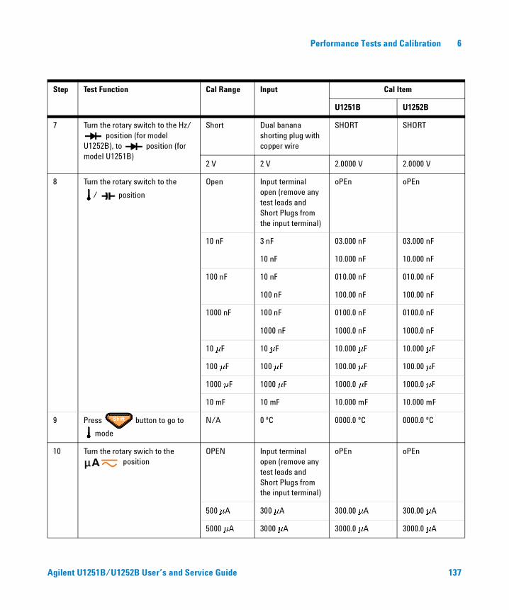
Performance Tests and Calibration 6
Step Test Function Cal Range Input Cal Item
U1251B U1252B
7 Turn the rotary switch to the Hz/ position (for model
U1252B), to position (for model U1251B)
Short Dual banana shorting plug with copper wire
SHORT SHORT
2 V 2 V 2.0000 V 2.0000 V
8 Turn the rotary switch to the
/ position
Open Input terminal open (remove any test leads and Short Plugs from the input terminal)
oPEn oPEn
10 nF 3 nF 03.000 nF 03.000 nF
10 nF 10.000 nF 10.000 nF
100 nF 10 nF 010.00 nF 010.00 nF
100 nF 100.00 nF 100.00 nF
1000 nF 100 nF 0100.0 nF 0100.0 nF
1000 nF 1000.0 nF 1000.0 nF
10 mF 10 mF 10.000 mF 10.000 mF
100 mF 100 mF 100.00 mF 100.00 mF
1000 mF 1000 mF 1000.0 mF 1000.0 mF
10 mF 10 mF 10.000 mF 10.000 mF
9 Press button to go to
mode
N/A 0 ºC 0000.0 ºC 0000.0 ºC
10 Turn the rotary swich to the position
OPEN Input terminal open (remove any test leads and Short Plugs from the input terminal)
oPEn oPEn
500 mA 300 mA 300.00 mA 300.00 mA
5000 mA 3000 mA 3000.0 mA 3000.0 mA
Agilent U1251B/U1252B User’s and Service Guide 137
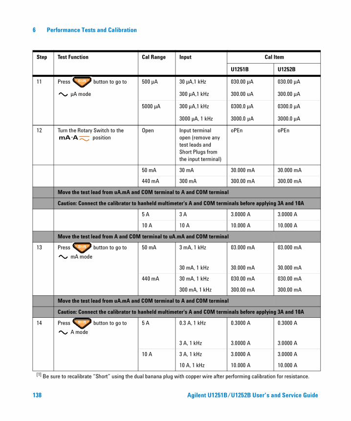
6 Performance Tests and Calibration
Step Test Function Cal Range Input Cal Item
U1251B U1252B
11 Press button to go to 500 µA 30 µA,1 kHz 030.00 µA 030.00 µA
µA mode 300 µA,1 kHz 300.00 uA 300.00 µA
5000 µA 300 µA,1 kHz 0300.0 µA 0300.0 µA
3000 µA, 1 kHz 3000.0 µA 3000.0 µA
12 Turn the Rotary Switch to the position
Open Input terminal open (remove any test leads and Short Plugs from the input terminal)
oPEn oPEn
50 mA 30 mA 30.000 mA 30.000 mA
440 mA 300 mA 300.00 mA 300.00 mA
Move the test lead from uA.mA and COM terminal to A and COM terminal
Caution: Connect the calibrator to hanheld multimeter's A and COM terminals before applying 3A and 10A
5 A 3 A 3.0000 A 3.0000 A
10 A 10 A 10.000 A 10.000 A
Move the test lead from A and COM terminal to uA.mA and COM terminal
13 Press button to go to
mA mode
50 mA 3 mA, 1 kHz 03.000 mA 03.000 mA
30 mA, 1 kHz 30.000 mA 30.000 mA
440 mA 30 mA, 1 kHz 030.00 mA 030.00 mA
300 mA, 1 kHz 300.00 mA 300.00 mA
Move the test lead from uA.mA and COM terminal to A and COM terminal
Caution: Connect the calibrator to hanheld multimeter's A and COM terminals before applying 3A and 10A
14 Press button to go to
A mode
5 A 0.3 A, 1 kHz 0.3000 A 0.3000 A
3 A, 1 kHz 3.0000 A 3.0000 A
10 A 3 A, 1 kHz 3.0000 A 3.0000 A
10 A, 1 kHz 10.000 A 10.000 A
[1] Be sure to recalibrate “Short” using the dual banana plug with copper wire after performing calibration for resistance.
138 Agilent U1251B/U1252B User’s and Service Guide
Performance Tests and Calibration 6
Finishing the Adjustment
1 Remove all the shorting plugs and connectors from the instrument.
2 Record the new Calibration Count.
3 Press and simultaneously to exit the Adjustment Mode. Power off and on again. The instrument will then be secured.
To Read the Calibration Count
You can query the instrument to determine how many calibrations have been performed.
When you receive your instrument, read the count to determine its initial value.
The count value increases by one for each calibration point, and a complete calibration will increase the value by many counts. The calibration count increments up to a maximum of 65535 after which it is set at 0. The calibration count can be read from the front panel after the instrument has been unsecured. Use the following procedure to read the calibration count from the front panel.
1 Press Adjustment Mode. The primary display shows the calibration count.
2 Take note of the count.
3 Press again to exit the calibration count mode.
NOTE Your instrument was calibrated before it left the factory.
Agilent U1251B/U1252B User’s and Service Guide 139
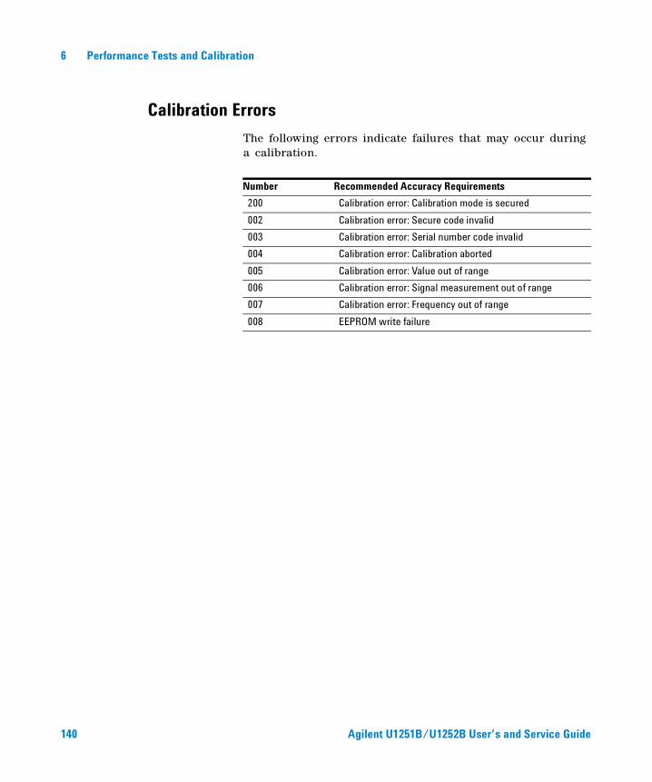
6 Performance Tests and Calibration
Calibration Errors
The following errors indicate failures that may occur during a calibration.
Number Recommended Accuracy Requirements
200 Calibration error: Calibration mode is secured
002 Calibration error: Secure code invalid
003 Calibration error: Serial number code invalid
004 Calibration error: Calibration aborted
005 Calibration error: Value out of range
006 Calibration error: Signal measurement out of range
007 Calibration error: Frequency out of range
008 EEPROM write failure
140 Agilent U1251B/U1252B User’s and Service Guide
Agilent U1251B and U1252B Handheld Digital MultimeterUser’s and Service Guide
7Specifications
DC Specifications 142
U1251B AC Specifications 144
U1252B AC Specifications 145
U1252B AC+DC Specifications 146
Temperature and Capacitance Specifications 147
U1251B & U1252B Frequency Specifications 148
Operating Specifications 152
General Specifications 154
This chapter lists the specifications of the handheld digital multimeter. When using the multimeter in an environment where there are electromagnetic interferences or significant electrostatic charges, the accuracy of measurement may be reduced.
141Agilent Technologies
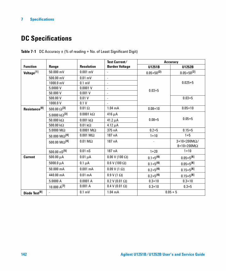
7 Specifications
DC Specifications
Table 7-1 DC Accuracy ± (% of reading + No. of Least Significant Digit)
Function Range ResolutionTest Current/ Burden Voltage
AccuracyU1251B U1252B
Voltage[1] 50.000 mV 0.001 mV - 0.05+50(2) 0.05+50[2]
500.00 mV 0.01 mV -
0.03+5
0.025+51000.0 mV 0.1 mV -5.0000 V 0.0001 V -50.000 V 0.001 V -500.00 V 0.01 V - 0.03+51000.0 V 0.1 V -
Resistance[8] 500.00 Ω[3] 0.01 Ω 1.04 mA 0.08+10 0.05+10
5.0000 kΩ[3] 0.0001 kΩ 416 μA
0.08+5 0.05+550.000 kΩ 0.001 kΩ 41.2 μA500.00 kΩ 0.01 kΩ 4.12 μA5.0000 MΩ 0.0001 MΩ 375 nA 0.2+5 0.15+5
50.000 MΩ[4] 0.001 MΩ 187 nA 1+10 1+5
500.00 MΩ[4] 0.01 MΩ 187 nA - 3+10<200MΩ/8+10>200MΩ
500.00 nS[5] 0.01 nS 187 nA 1+20 1+10
Current 500.00 μA 0.01 μA 0.06 V (100 Ω) 0.1+5(6) 0.05+5[6] 5000.0 μA 0.1 μA 0.6 V (100 Ω) 0.1+5(6) 0.05+5[6] 50.000 mA 0.001 mA 0.09 V (1 Ω) 0.2+5(6) 0.15+5[6]
440.00 mA 0.01 mA 0.9 V (1 Ω) 0.2+5(6) 0.15+5[6]
5.0000 A 0.0001 A 0.2 V (0.01 Ω) 0.3+10 0.3+10
10.000 A[7] 0.001 A 0.4 V (0.01 Ω) 0.3+10 0.3+5
Diode Test[8] - 0.1 mV 1.04 mA 0.05 + 5
142 Agilent U1251B/U1252B User’s and Service Guide
Specifications 7
[1] Input impedance: Refer to Table 7-6.
[2] The accuracy could be 0.05 %+10 for U1251B and 0.05 %+5 for U1252B. Always use the Null function to zero out the thermal effect before measuring the signal.
[3] The accuracy of 500 Ω and 5 kΩ is specified after Null function, which is used to subtract the test lead resistance and the thermal effect
[4] For the range of 50 Ω/500 MΩ, the R.H. is specified for <60 %.
[5] The accuracy is specified for <50 nS and after Null function with open test lead.
[6] Always use the Null function to zero out thermal effect with open test lead before measuring the signal. If the Null function is not used, add 20 counts to the DC current accuracy. Thermal effect could occur due to the following:
Wrong procedures used to measure the high voltage of 50 V to 1000 V for resistance, diode, and mV measurements.
After battery-charging has completed.
After measuring current greater than 440 mA. Thus we recommend that the meter be left to cool down for a period which is twice the measuring time used.
[7] Current can be measured up to 10 A continuously. Add 0.5 % to the specified accuracy if the signal measured is in the range of 10 A to 20 A and for a period of up to 30 seconds. After measuring current > 10 A, leave the meter to cool down for twice the measuring time used before application of low current measurement.
[8] Maximum open voltage: <+4.2 V.
Agilent U1251B/U1252B User’s and Service Guide 143
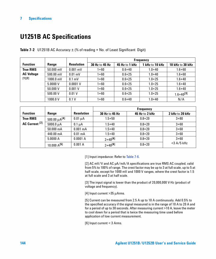
7 Specifications
U1251B AC Specifications
Table 7-2 U1251B AC Accuracy ± (% of reading + No. of Least Significant Digit)
[1] Input impedance: Refer to Table 7-6.
[2] AC mV/V and AC µA/mA/A specifications are true RMS AC coupled, valid from 5% to 100% of range. The crest factor may be up to 3 at full scale, up to 5 at half-scale, except for 1000 mV and 1000 V ranges, where the crest factor is 1.5 at full scale and 3 at half scale.
[3] The input signal is lower than the product of 20,000,000 V-Hz (product of voltage and frequency).
[4] Input current >35 μArms.
[5] Current can be measured from 2.5 A up to 10 A continuously. Add 0.5% to the specified accuracy if the signal measured is in the range of 10 A to 20 A and for a period of up to 30 seconds. After measuring current >10 A, leave the meter to cool down for a period that is twice the measuring time used before application of low current measurement.
[6] Input current < 3 Arms.
Function Range ResolutionFrequency
30 Hz to 45 Hz 45 Hz to 1 kHz 1 kHz to 10 kHz 10 kHz to 30 kHzTrue RMSAC Voltage [1][2]
50.000 mV 0.001 mV 1+60 0.6+40 1.0+40 1.6+60500.00 mV 0.01 mV 1+60 0.6+25 1.0+40 1.6+601000.0 mV 0.1 mV 1+60 0.6+25 1.0+25 1.6+405.0000 V 0.0001 V 1+60 0.6+25 1.0+25 1.6+4050.000 V 0.001 V 1+60 0.6+25 1.0+25 1.6+40500.00 V 0.01 V 1+60 0.6+25 1.0+25 1.6+40[3]
1000.0 V 0.1 V 1+60 0.6+40 1.0+40 N/A
Function Range ResolutionFrequency
30 Hz to 45 Hz 45 Hz to 2 kHz 2 kHz to 20 kHzTrue RMS
AC Current [2]
500.00 μA[4] 0.01 μA 1.5+50 0.8+20 3+80
5000.0 μA 0.1 μA 1.5+40 0.8+20 3+6050.000 mA 0.001 mA 1.5+40 0.8+20 3+60440.00 mA 0.01 mA 1.5+40 0.8+20 3+605.0000 A 0.0001 A 2+40[6] 0.8+20 3+60
<3 A/5 kHz10.000 A[5] 0.001 A 2+40[6] 0.8+20
144 Agilent U1251B/U1252B User’s and Service Guide
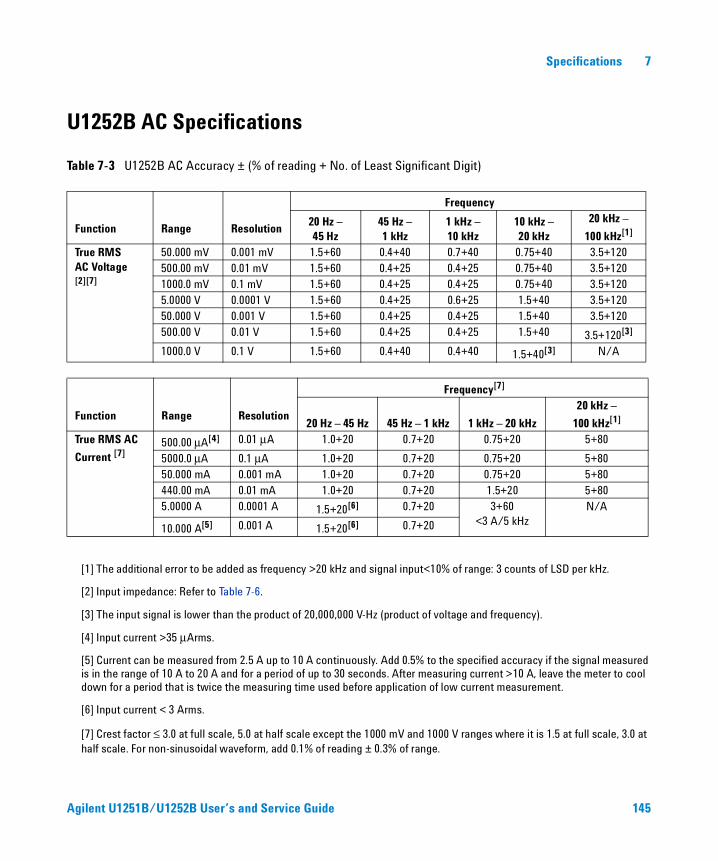
Specifications 7
U1252B AC Specifications
Table 7-3 U1252B AC Accuracy ± (% of reading + No. of Least Significant Digit)
[1] The additional error to be added as frequency >20 kHz and signal input<10% of range: 3 counts of LSD per kHz.
[2] Input impedance: Refer to Table 7-6.
[3] The input signal is lower than the product of 20,000,000 V-Hz (product of voltage and frequency).
[4] Input current >35 μArms.
[5] Current can be measured from 2.5 A up to 10 A continuously. Add 0.5% to the specified accuracy if the signal measured is in the range of 10 A to 20 A and for a period of up to 30 seconds. After measuring current >10 A, leave the meter to cool down for a period that is twice the measuring time used before application of low current measurement.
[6] Input current < 3 Arms.
[7] Crest factor ≤ 3.0 at full scale, 5.0 at half scale except the 1000 mV and 1000 V ranges where it is 1.5 at full scale, 3.0 at half scale. For non-sinusoidal waveform, add 0.1% of reading ± 0.3% of range.
Function Range Resolution
Frequency
20 Hz –45 Hz
45 Hz – 1 kHz
1 kHz –10 kHz
10 kHz –20 kHz
20 kHz –
100 kHz[1]
True RMSAC Voltage [2][7]
50.000 mV 0.001 mV 1.5+60 0.4+40 0.7+40 0.75+40 3.5+120500.00 mV 0.01 mV 1.5+60 0.4+25 0.4+25 0.75+40 3.5+1201000.0 mV 0.1 mV 1.5+60 0.4+25 0.4+25 0.75+40 3.5+1205.0000 V 0.0001 V 1.5+60 0.4+25 0.6+25 1.5+40 3.5+12050.000 V 0.001 V 1.5+60 0.4+25 0.4+25 1.5+40 3.5+120500.00 V 0.01 V 1.5+60 0.4+25 0.4+25 1.5+40 3.5+120[3]
1000.0 V 0.1 V 1.5+60 0.4+40 0.4+40 1.5+40[3] N/A
Function Range Resolution
Frequency[7]
20 Hz – 45 Hz 45 Hz – 1 kHz 1 kHz – 20 kHz
20 kHz –
100 kHz[1]
True RMS AC
Current [7]
500.00 μA[4] 0.01 μA 1.0+20 0.7+20 0.75+20 5+80
5000.0 μA 0.1 μA 1.0+20 0.7+20 0.75+20 5+8050.000 mA 0.001 mA 1.0+20 0.7+20 0.75+20 5+80440.00 mA 0.01 mA 1.0+20 0.7+20 1.5+20 5+805.0000 A 0.0001 A 1.5+20[6] 0.7+20 3+60
<3 A/5 kHzN/A
10.000 A[5] 0.001 A 1.5+20[6] 0.7+20
Agilent U1251B/U1252B User’s and Service Guide 145
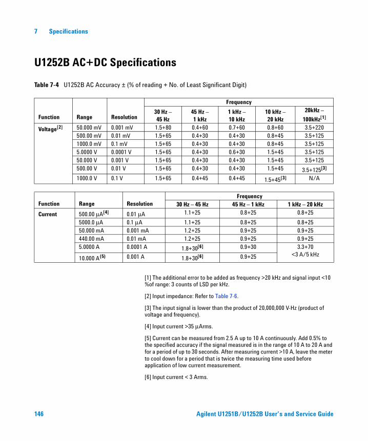
7 Specifications
U1252B AC+DC Specifications
Table 7-4 U1252B AC Accuracy ± (% of reading + No. of Least Significant Digit)
[1] The additional error to be added as frequency >20 kHz and signal input <10 %of range: 3 counts of LSD per kHz.
[2] Input impedance: Refer to Table 7-6.
[3] The input signal is lower than the product of 20,000,000 V-Hz (product of voltage and frequency).
[4] Input current >35 μArms.
[5] Current can be measured from 2.5 A up to 10 A continuously. Add 0.5% to the specified accuracy if the signal measured is in the range of 10 A to 20 A and for a period of up to 30 seconds. After measuring current >10 A, leave the meter to cool down for a period that is twice the measuring time used before application of low current measurement.
[6] Input current < 3 Arms.
Function Range Resolution
Frequency
30 Hz –45 Hz
45 Hz –1 kHz
1 kHz –10 kHz
10 kHz –20 kHz
20kHz –
100kHz[1]
Voltage[2] 50.000 mV 0.001 mV 1.5+80 0.4+60 0.7+60 0.8+60 3.5+220500.00 mV 0.01 mV 1.5+65 0.4+30 0.4+30 0.8+45 3.5+1251000.0 mV 0.1 mV 1.5+65 0.4+30 0.4+30 0.8+45 3.5+1255.0000 V 0.0001 V 1.5+65 0.4+30 0.6+30 1.5+45 3.5+12550.000 V 0.001 V 1.5+65 0.4+30 0.4+30 1.5+45 3.5+125500.00 V 0.01 V 1.5+65 0.4+30 0.4+30 1.5+45 3.5+125[3]
1000.0 V 0.1 V 1.5+65 0.4+45 0.4+45 1.5+45[3] N/A
Function Range ResolutionFrequency
30 Hz – 45 Hz 45 Hz – 1 kHz 1 kHz – 20 kHz
Current 500.00 μA[4] 0.01 μA 1.1+25 0.8+25 0.8+25
5000.0 μA 0.1 μA 1.1+25 0.8+25 0.8+2550.000 mA 0.001 mA 1.2+25 0.9+25 0.9+25440.00 mA 0.01 mA 1.2+25 0.9+25 0.9+255.0000 A 0.0001 A 1.8+30[6] 0.9+30 3.3+70
<3 A/5 kHz10.000 A(5) 0.001 A 1.8+30[6] 0.9+25
146 Agilent U1251B/U1252B User’s and Service Guide
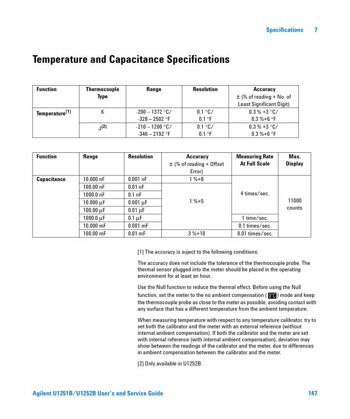
Specifications 7
Temperature and Capacitance Specifications
[1] The accuracy is suject to the following conditions:
The accuracy does not include the tolerance of the thermocouple probe. The thermal sensor plugged into the meter should be placed in the operating environment for at least an hour.
Use the Null function to reduce the thermal effect. Before using the Null
function, set the meter to the no ambient compensation ( ) mode and keep the thermocouple probe as close to the meter as possible, avoiding contact with any surface that has a different temperature from the ambient temperature.
When measuring temperature with respect to any temperature calibrator, try to set both the calibrator and the meter with an external reference (without internal ambient compensation). If both the calibrator and the meter are set with internal reference (with internal ambient compensation), deviation may show between the readings of the calibrator and the meter, due to differences in ambient compensation between the calibrator and the meter.
[2] Only available in U1252B.
Function ThermocoupleType
Range Resolution Accuracy ± (% of reading + No. of Least Significant Digit)
Temperature[1] K -200 – 1372 °C/-328 – 2502 °F
0.1 °C/0.1 °F
0.3 % +3 °C/ 0.3 %+6 °F
J(2) -210 – 1200 °C/-346 – 2192 °F
0.1 °C/0.1 °F
0.3 % +3 °C/0.3 %+6 °F
Function Range Resolution Accuracy ± (% of reading + Offset
Error)
Measuring Rate At Full Scale
Max. Display
Capacitance 10.000 nF 0.001 nF 1 %+8
4 times/sec.11000 counts
100.00 nF 0.01 nF
1 %+51000.0 nF 0.1 nF10.000 μF 0.001 μF100.00 μF 0.01 μF1000.0 μF 0.1 μF 1 time/sec.10.000 mF 0.001 mF 0.1 times/sec.100.00 mF 0.01 mF 3 %+10 0.01 times/sec.
Agilent U1251B/U1252B User’s and Service Guide 147
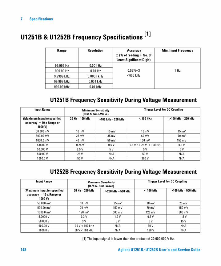
7 Specifications
U1251B & U1252B Frequency Specifications
U1251B Frequency Sensitivity During Voltage Measurement
U1252B Frequency Sensitivity During Voltage Measurement
[1] The input signal is lower than the product of 20,000,000 V-Hz.
Range Resolution Accuracy± (% of reading + No. of Least Significant Digit)
Min. Input Frequency
99.999 Hz 0.001 Hz0.02%+3<600 kHz
1 Hz999.99 Hz 0.01 Hz
9.9999 kHz 0.0001 kHz
99.999 kHz 0.001 kHz
999.99 kHz 0.01 kHz
Input Range Minimum Sensitivity(R.M.S. Sine-Wave)
Trigger Level For DC Coupling
(Maximum input for specified accuracy = 10 x Range or
1000 V)
20 Hz – 100 kHz >100 kHz – 200 kHz < 100 kHz >100 kHz – 200 kHz
50.000 mV 10 mV 15 mV 10 mV 15 mV
500.00 mV 25 mV 35 mV 60 mV 70 mV
1000.0 mV 40 mV 50 mV 100 mV 150 mV
5.0000 V 0.25 V 0.5 V 0.5 V / 1.25 V (< 100 Hz) 0.6 V50.000 V 2.5 V 5 V 5 V 6 V
500.00 V 25 V N/A 50 V N/A
1000.0 V 50 V N/A 300 V N/A
Input Range Minimum Sensitivity(R.M.S. Sine-Wave)
Trigger Level For DC Coupling
(Maximum input for specified accuracy = 10 x Range or
1000 V)
20 Hz – 200 kHz >200 kHz – 500 kHz < 100 kHz >100 kHz – 500 kHz
50.000 mV 10 mV 25 mV 10 mV 25 mV
500.00 mV 70 mV 150 mV 70 mV 150 mV
1000.0 mV 120 mV 300 mV 120 mV 300 mV5.0000 V 0.3 V 1.2 V 0.6 V 1.5 V
50.000 V 3 V 5 V 6 V 15 V
500.00 V 30 V < 100 kHz N/A 60 V N/A
1000.0 V 50 V < 100 kHz N/A 120 V N/A
[1]
148 Agilent U1251B/U1252B User’s and Service Guide
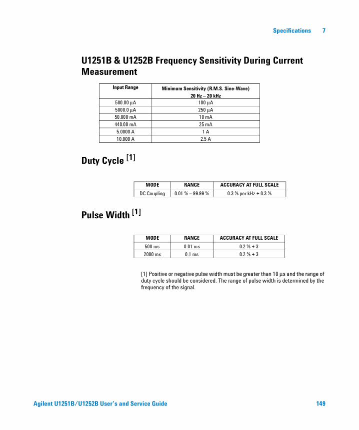
Specifications 7
U1251B & U1252B Frequency Sensitivity During Current Measurement
Duty Cycle [1]
Pulse Width [1]
[1] Positive or negative pulse width must be greater than 10 μs and the range of duty cycle should be considered. The range of pulse width is determined by the frequency of the signal.
Input Range Minimum Sensitivity (R.M.S. Sine-Wave)20 Hz – 20 kHz
500.00 μA 100 μA
5000.0 μA 250 μA50.000 mA 10 mA
440.00 mA 25 mA
5.0000 A 1 A
10.000 A 2.5 A
MODE RANGE ACCURACY AT FULL SCALE
DC Coupling 0.01 % – 99.99 % 0.3 % per kHz + 0.3 %
MODE RANGE ACCURACY AT FULL SCALE
500 ms 0.01 ms 0.2 % + 3
2000 ms 0.1 ms 0.2 % + 3
Agilent U1251B/U1252B User’s and Service Guide 149

7 Specifications
U1252B Frequency Counter Specifications
Divide 1 (secondary display “-1-”)
Divide 100 (secondary display “-100-”)
PEAK HOLD (Capturing changes)
[1] The maximum measurement level is < 30 Vpp.
[2] All frequency counters are susceptible to error when measuring low-voltage, low-frequency signals. Shielding inputs from picking up external noise is critical for minimizing measurement errors. For non-square wave signals, an additional 5 counts need to be added.
[3] The minimum measurement frequency of low frequency is set by power-on option to speed up the measurement rate.
Range Resolution Accuracy ± (% of reading + No. of Least Significant Digit)
Sensitivity Min. Input Frequency
99.999 Hz 0.001 Hz 0.02%+3[2]
100 mV R.M.S.0.5 Hz
999.99 Hz 0.01 Hz
0.002%+5, <985 kHz
9.9999 kHz 0.0001 kHz
99.999 kHz 0.001 kHz
999.99 kHz 0.01 kHz 200 mV R.M.S.
9.9999 MHz 0.0001 MHz
Range Resolution Accuracy± (% of reading + No. of Least Significant Digit)
Sensitivity Min. Input Frequency
9.9999 MHz 0.0001 MHz 0.002 %+5,<20 MHz
400 mV R.M.S. 1 MHz
99.99 MHz 0.001 MHz 600 mV R.M.S.
SIGNAL WIDTH ACCURACY FOR DC mV/VOLTAGE/CURRENT
Single event > 1 ms 2% + 400 for all ranges
Repetitive > 250 μs 2% + 1000 for all ranges
150 Agilent U1251B/U1252B User’s and Service Guide
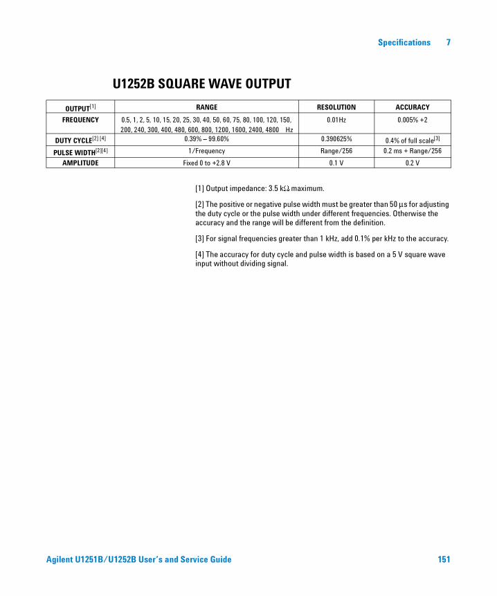
Specifications 7
U1252B SQUARE WAVE OUTPUT
[1] Output impedance: 3.5 kW maximum.
[2] The positive or negative pulse width must be greater than 50 μs for adjusting the duty cycle or the pulse width under different frequencies. Otherwise the accuracy and the range will be different from the definition.
[3] For signal frequencies greater than 1 kHz, add 0.1% per kHz to the accuracy.
[4] The accuracy for duty cycle and pulse width is based on a 5 V square wave input without dividing signal.
OUTPUT[1] RANGE RESOLUTION ACCURACY
FREQUENCY 0.5, 1, 2, 5, 10, 15, 20, 25, 30, 40, 50, 60, 75, 80, 100, 120, 150, 200, 240, 300, 400, 480, 600, 800, 1200, 1600, 2400, 4800 Hz
0.01Hz 0.005% +2
DUTY CYCLE[2] [4] 0.39% – 99.60% 0.390625% 0.4% of full scale[3]
PULSE WIDTH[2][4] 1/Frequency Range/256 0.2 ms + Range/256
AMPLITUDE Fixed 0 to +2.8 V 0.1 V 0.2 V
Agilent U1251B/U1252B User’s and Service Guide 151
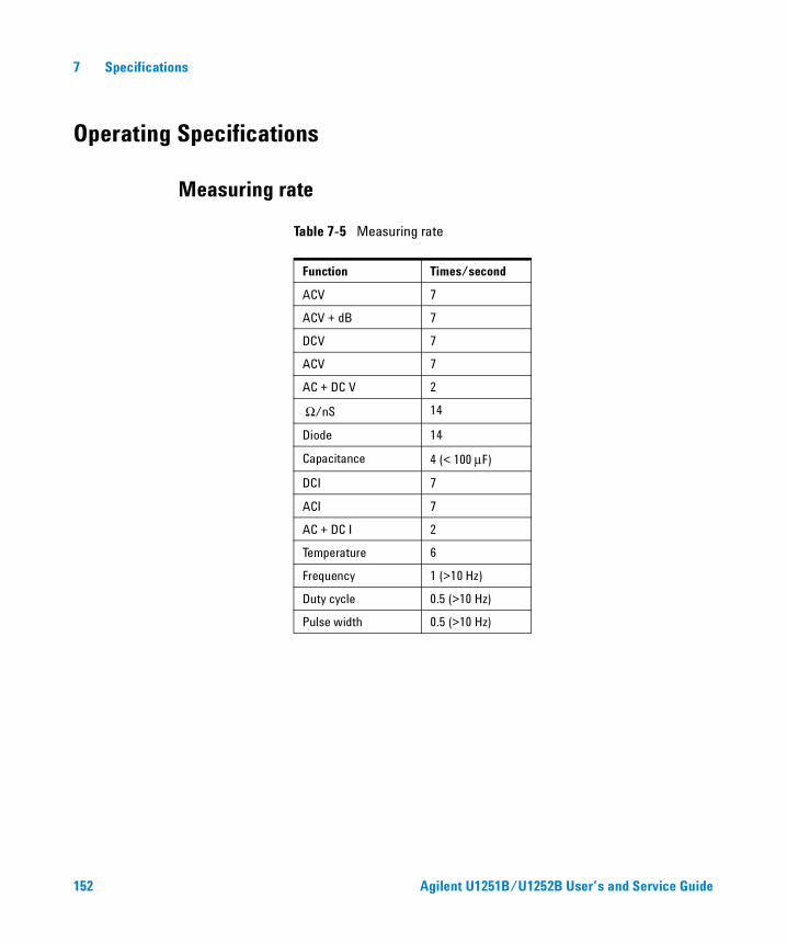
7 Specifications
Operating Specifications
Measuring rate
Table 7-5 Measuring rate
Function Times/second
ACV 7
ACV + dB 7
DCV 7
ACV 7
AC + DC V 2
Ω/nS 14
Diode 14
Capacitance 4 (< 100 μF)
DCI 7
ACI 7
AC + DC I 2
Temperature 6
Frequency 1 (>10 Hz)
Duty cycle 0.5 (>10 Hz)
Pulse width 0.5 (>10 Hz)
152 Agilent U1251B/U1252B User’s and Service Guide
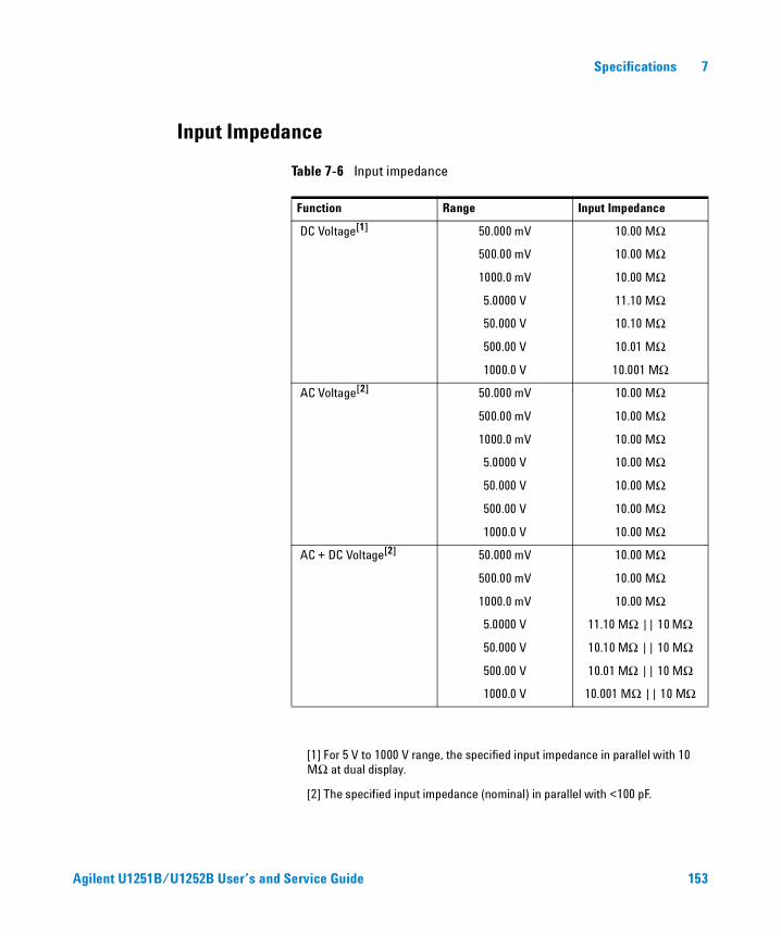
Specifications 7
Input Impedance
Table 7-6 Input impedance
[1] For 5 V to 1000 V range, the specified input impedance in parallel with 10 MΩ at dual display.
[2] The specified input impedance (nominal) in parallel with <100 pF.
Function Range Input Impedance
DC Voltage[1] 50.000 mV 10.00 MΩ
500.00 mV 10.00 MΩ
1000.0 mV 10.00 MΩ
5.0000 V 11.10 MΩ
50.000 V 10.10 MΩ
500.00 V 10.01 MΩ
1000.0 V 10.001 MΩ
AC Voltage[2] 50.000 mV 10.00 MΩ
500.00 mV 10.00 MΩ
1000.0 mV 10.00 MΩ
5.0000 V 10.00 MΩ
50.000 V 10.00 MΩ
500.00 V 10.00 MΩ
1000.0 V 10.00 MΩ
AC + DC Voltage[2] 50.000 mV 10.00 MΩ
500.00 mV 10.00 MΩ
1000.0 mV 10.00 MΩ
5.0000 V 11.10 MΩ || 10 MΩ
50.000 V 10.10 MΩ || 10 MΩ
500.00 V 10.01 MΩ || 10 MΩ
1000.0 V 10.001 MΩ || 10 MΩ
Agilent U1251B/U1252B User’s and Service Guide 153
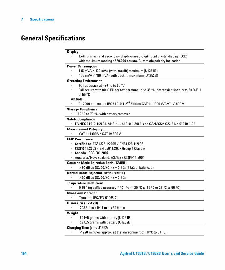
7 Specifications
General Specifications
Display • Both primary and secondary displays are 5-digit liquid crystal display (LCD)
with maximum reading of 50,000 counts. Automatic polarity indication.
Power Consumption• 105 mVA / 420 mVA (with backlit) maximum (U1251B)• 165 mVA / 480 mVA (with backlit) maximum (U1252B)
Operating Environment • Full accuracy at –20 °C to 55 °C • Full accuracy to 80 % RH for temperature up to 35 °C, decreasing linearly to 50 % RH
at 55 °CAltitude:• 0 - 2000 meters per IEC 61010-1 2nd Edition CAT III, 1000 V/CAT IV, 600 V
Storage Compliance• – 40 °C to 70 °C, with battery removed
Safety Compliance• EN/IEC 61010-1:2001, ANSI/UL 61010-1:2004, and CAN/CSA-C22.2 No.61010-1-04
Measurement Category• CAT III 1000 V/ CAT IV 600 V
EMC Compliance• Certified to IEC61326-1:2005 / EN61326-1:2006• CISPR 11:2003 / EN 55011:2007 Group 1 Class A• Canada: ICES-001:2004• Australia/New Zealand: AS/NZS CISPR11:2004
Common Mode Rejection Ratio (CMRR)• > 90 dB at DC, 50/60 Hz + 0.1 % (1 kΩ unbalanced)
Normal Mode Rejection Ratio (NMRR)• > 60 dB at DC, 50/60 Hz + 0.1 %
Temperature Coefficient• 0.15 * (specified accuracy)/ °C (from -20 °C to 18 °C or 28 °C to 55 °C)
Shock and Vibration • Tested to IEC/EN 60068-2
Dimension (HxWxD)• 203.5 mm x 94.4 mm x 59.0 mm
Weight• 504±5 grams with battery (U1251B) • 527±5 grams with battery (U1252B)
Charging Time (only U1252)• < 220 minutes approx. at the environment of 10 °C to 30 °C.
154 Agilent U1251B/U1252B User’s and Service Guide
Specifications 7
Warranty • 3 years for main unit• 3 months for standard accessories unless otherwise specified
Agilent U1251B/U1252B User’s and Service Guide 155

7 Specifications
156 Agilent U1251B/U1252B User’s and Service Guide
© Agilent Technologies, Inc. 2009
Printed in MalaysiaFirst Edition, December 01, 2009
U1251-90036
www.agilent.com
Agilent Technologies
Contact usTo obtain service, warranty or technical support assistance, contact us at the following phone numbers:
United States:(tel) 800 829 4444 (fax) 800 829 4433Canada:(tel) 877 894 4414 (fax) 800 746 4866China:(tel) 800 810 0189 (fax) 800 820 2816Europe:(tel) 31 20 547 2111Japan:(tel) (81) 426 56 7832 (fax) (81) 426 56 7840Korea:(tel) (080) 769 0800 (fax) (080) 769 0900Latin America:(tel) (305) 269 7500Taiwan:(tel) 0800 047 866 (fax) 0800 286 331Other Asia Pacific Countries:(tel) (65) 6375 8100 (fax) (65) 6755 0042
Or visit Agilent worlwide Web at:www.agilent.com/find/assist
Product specifications and descriptions in this document are subject to change without notice.Always refer to the Agilent Web site for the latest revision.