Embed Size (px)
Citation preview

Agricultural trailer product catalogue Europe
Edition 1
Innovative Vehicle Solutions


3Edition 1 Innovative Vehicle Solutions
Agricultural trailer product catalogue
Introduction
This catalogue provides an overview of the Haldex product range for agricultural
trailers. For each product group you will find information that will make it easy to find
the requested item.
Item inclusion or exclusion does not determine availability. For availability, please
contact Haldex directly
If you cannot find an item:
› Check Findex at www.haldex.com/Findex or
in www.haldex.com/trailer-application guide
› Contact Haldex directly
We hope you find this catalogue useful, and we welcome all feedback and suggestions
for improvement.
Thank you for choosing Haldex.
INTRODUCTION
Although Haldex does its best to ensure the accuracy of all information in this catalogue, Haldex assume no responsibility for any issues that may arise as a result of
inaccurate data in this catalogue. Haldex reserves the right to amend this information without notice.
Findex Trailer Application
Guide

4 Innovative Vehicle Solutions Edition 1
PRODUCT OVERVIEWAgricultural trailer product catalogue
Relay emergency valve
Coupling head
Automatic drain valve
Air tank
Page60
Page50
Page66
Page42

5Edition 1 Innovative Vehicle Solutions
PRODUCT OVERVIEWAgricultural trailer product catalogue
Load sensing valve
EB+ Gen3Electronic braking
system
Brake chamberDouble diaphragm spring brake
Blue Seal
AA1, S-ABAAutomatic brake adjusters
Page128
Page100
Page135
Page95
Page116
Levelling valve
Page140

6 Innovative Vehicle Solutions Edition 1
Agricultural trailer product catalogueCONTENTS
Air distribution Page
Saddle for air tank 40
Air tank 42
Air coil 44
Schematic design Page
380 102 950 27
380 095 550 29
380 060 960 31
380 066 250 33
380 071 508 35
380 082 160 37
Air treatment Page
In-line filter 48
Manual drain valve 49
Automatic drain valve 50
DIN/ISO Symbols Page
Introduction 10
Symbols 11
Ports 22

7Edition 1 Innovative Vehicle Solutions
Agricultural trailer product catalogue
Air suspension Page
Levelling valve 140
CONTENTS
Actuation Page
Brake chamber 116
Double diaphragm spring brake - Blue Seal 128
Piston cylinder 132
Automatic brake adjusters 135
Air brake Page
Check valve 54
Pressure protection valve 55
Dummy coupling 58
Coupling head 60
Relay emergency valve 66
Pressure limiting valve 69
Shunt valve 74
Park and shunt valve 77
Relay valve 79
Quick release valve 81
Regulating valve 85
Mechanical load sensing valve 89
Pneumatic load sensing valve 95
Electronic braking system 100

8 Innon vative Vehe icle SSolutions Edition 111
AgAgAgAgriririiicucucuc ltlturu al traailerrprprrododducuctt cacaatatatalolologuguee

99EEddition 11 Innovaativeve VVehiclee SSolutions
Agricultural trailerprprododucuct t cacaatatttaloologuguee
DIN/ISO SYMBOLS
Introduction 10
Symbols 11
Controls 12
Warning devices 13
Test and filling connections 13
Valves 14
Ports 22

Introduction
The following drawing and function symbols comply with DIN 74 253, January 1994 edition 1, and DIN ISO 1219, June 2012
edition.
The drawing symbols (DIN 74 253) can be used for the schematic representation of braking systems (circuit plan) in motor vehicles.
The ports on the symbols are shown in accordance with DIN ISO 6786, December 1981 edition. These identifications are not part of
the symbols, but can be added to improve comprehension.
The function symbols (DIN ISO 1219) are intended to explain the internal operations of components or parts thereof. They consist of
one or more basic signs and in general one or more function signs.
The components are shown in the off position in circuit diagrams, and if this is not present, in the initial position of the control
system. If this is not the case, a note must be provided. e.g. working position.
Note:
The drawing and function symbols shown on the following pages are an extract from the corresponding DIN. Only those symbols are
shown here that are necessary for trailer vehicles.
10 Innovative Vehicle Solutions Edition 1
Agricultural trailer product catalogue
DIN/ISO SYMBOLSIntroduction

Drawing symbols in accordance with DIN 74253
Function symbols in accordance with DIN ISO 1219
Description
General line
Line marking:
direction of flow and medium
Pneumatics
Hydraulics
Electrics
Crosses:
with connection
without connection
Arrangement of lines:
loop
Flexible lead/line for connecting
moveable parts
Coiled tubing
Throttle in the line
Circle symbol for different applications:
pumps, compressors, motors, etc
Square and rectangle:
symbols for equipment, cylinders and
controls
Diamond for filters, separators, etc.
11Edition 1 Innovative Vehicle Solutions
Agricultural trailer product catalogue
DIN/ISO SYMBOLS
DIN
/ IS
O S
ymb
ols

Drawing symbols in accordance with DIN 74253
Function symbols in accordance with DIN ISO 1219
Description
Border for sub-assemblies:
several combined in the block
Arrows to show:
the direction of flow
Rotability, direction of rotation
Travel and direction of flow within the
equipment
Diagonal arrows as sign of adjustability
Controls
Linkage, lever and mechanical
connection
Mechanical catch for pre defined switch
position
Mechanical control:
general
Rotating
Via linkage
Mechanical control via hand lever
Mechanical control via running plate
Triggers:
pneumatics
hydraulics
via control surfaces
via cut-off ports in the equipment
12 Innovative Vehicle Solutions Edition 1
Agricultural trailer product catalogue
DIN/ISO SYMBOLS

Drawing symbols in accordance with DIN 74253
Function symbols in accordance with DIN ISO 1219
Description
Multiple control:
twin
via pressure drop
via increase in pressure
triple
Electrical control:
via solenoid valve
Automatic brake adjuster:
manual
automatic
Warning devices
Pressure gauge:
single
Pressure gauge:
double
low pressure indicator
lamps
buzzers
Test and filling connections
Testing and filling ports :
within the leads
on the equipment
on the equipment with mechanical
control
Filling connection only:
no possibility to remove
13Edition 1 Innovative Vehicle Solutions
Agricultural trailer product catalogue
DIN/ISO SYMBOLS
DIN
/ IS
O S
ymb
ols

Drawing symbols in accordance with DIN 74253
Function symbols in accordance with DIN ISO 1219
Description
Valves
General valve:
square symbol
3/2-way valves manually operated
Twin release valve
Trailer Control Module
Non return valve
Non return valve with restricted backflow
One-way restrictor
Two-way valve
14 Innovative Vehicle Solutions Edition 1
Agricultural trailer product catalogue
DIN/ISO SYMBOLS

Drawing symbols in accordance with DIN 74253
Function symbols in accordance with DIN ISO 1219
Description
Valves
Throttle valve
Quick exhaust valve
Proportioning pressure regulator (control
valve) with kinked characteristic curve
Proportioning pressure regulator (control
valve) with straight characteristic curve
Overflow valve:
without backflow
with backflow
with restricted backflow
Height control valve:
with one energy outlet
with two unequal energy outlets
15Edition 1 Innovative Vehicle Solutions
Agricultural trailer product catalogue
DIN/ISO SYMBOLS
DIN
/ IS
O S
ymb
ols

Drawing symbols in accordance with DIN 74253
Function symbols in accordance with DIN ISO 1219
Description
Valves
Water-drainage valve manually operated
Automatically operated
Controlled by impulse
Safety valve
Relay valve
With solenoid relay valve
Solenoid valve
Electromagnetically operated brake valve
with pressure control
16 Innovative Vehicle Solutions Edition 1
Agricultural trailer product catalogue
DIN/ISO SYMBOLS

Drawing symbols in accordance with DIN 74253
Function symbols in accordance with DIN ISO 1219
Description
Valves
Control valve
Automatic braking force regulator
mechanically controlled
Pneumatically controlled
Trailer brake valve:
single line
with release valve
with manually adjustable braking force
regulator
with release valve and manually
adjustable braking force regulator
17Edition 1 Innovative Vehicle Solutions
Agricultural trailer product catalogue
DIN/ISO SYMBOLS
DIN
/ IS
O S
ymb
ols

Drawing symbols in accordance with DIN 74253
Function symbols in accordance with DIN ISO 1219
Description
Valves
Trailer brake valve dual line without
release valve
Trailer brake valve dual line:
with release valve
with manually adjustable braking force
regulator
with manually adjustable braking force
regulator and release valve
Pressure control valve
Manually operated
18 Innovative Vehicle Solutions Edition 1
Agricultural trailer product catalogue
DIN/ISO SYMBOLS

Drawing symbols in accordance with DIN 74253
Function symbols in accordance with DIN ISO 1219
Description
Valves
Compressed air cylinder
Hydraulic cylinder:
master cylinder, single circuit
master cylinder, dual circuit
Hydraulic cylinder:
slave cylinder, single circuit
slave cylinder, dual circuit
Piston spring brake:
pulling with release device
pressing with release device
Double diaphragm spring brake:
pressing with release device
Servo cylinder with hydraulic master
cylinder
Air brake tank
Fluid container
19Edition 1 Innovative Vehicle Solutions
Agricultural trailer product catalogue
DIN/ISO SYMBOLS
DIN
/ IS
O S
ymb
ols

Drawing symbols in accordance with DIN 74253
Function symbols in accordance with DIN ISO 1219
Description
Valves
Suction filter
Line filter
Shut-off valve:
without venting
with venting
Coupling head :
without shut-off device
with shut-off device
with shut-off device and two connection
Coupled
with filter
with filter and test connection
Dummy coupling coupled
Electric switch, no contact, mechanically
controlled
No contact, pneumatically controlled
Contact, pneumatically controlled
General symbol
20 Innovative Vehicle Solutions Edition 1
Agricultural trailer product catalogue
DIN/ISO SYMBOLS
Drawing symbols in accordance with DIN 74253
Function symbols in accordance with DIN ISO 1219
Description
Valves
Pneumatic bellows
COLAS:
dual circuit
single circuit
ILAS:
manually controlled
manually controlled and electrically
controlled
automatically controlled
automatically controlled with electric
control
ILAS III:
manually controlled
automatically controlled
ILAS-E
Venting
Venting outlet ventilation
With vent line
Metal bellows
21Edition 1 Innovative Vehicle Solutions
Agricultural trailer product catalogue
DIN/ISO SYMBOLS
DIN
/ IS
O S
ymb
ols

Ports
Identification of ports on components in air braking systems as per DIN ISO 6786
A standard has been drawn up in FAKRA and ISO regarding the identification of ports on components in air braking systems, and
appeared as a Standard under the number DIN ISO 6786 in December 1981.
This Standard includes DIN 74 254, 04/1976 edition, in which the international standard ISO 6786, 06/1980 edition was
incorporated unchanged.
The main features of the standard are that ports on components are:
Identified by numbers and not letters. This avoids the possibility of letters being incorrectly understood in different countries.
Not numbered consecutively, but instead the numbers of the port identification should themselves give an indication of the function
of the port in the unit.
The identification consists of a number with up to two digits. The meaning of the first digit are:
› 0 vacuum connection
› 1 supply port
› 2 delivery port
› 3 port to atmosphere (exhaust)
› 4 control port
› 5 not used
› 6 not used
› 7 antifreeze port
› 8 lub. oil port (compressor)
› 9 coolant port (compressor)
A second digit is then to be added if a number of ports of the same kind are possible or present, e.g. where there are several circuits.
The meaning of the second digit is left to the manufacturer. It should start at 1 and rise consecutively, e.g. 21, 12, 43, etc.
22 Innovative Vehicle Solutions Edition 1
Agricultural trailer product catalogue
DIN/ISO SYMBOLSPorts

For example:
› 21 = 1st delivery port
› 12 = 2nd supply port
› 43 = 3rd control port
If a modular system is employed, it may be necessary to deviate from this.
The following numbers may not be freely allocated:
› 71 antifreeze inlet
› 72 antifreeze outlet
› 81 lub. oil inlet
› 82 lub. oil inlet
› 91 coolant inlet
› 92 coolant outlet
Where there are a number of ports of the same kind coming from a single space, they are not distinguished. They are given the same
identification. If a port can fulfil several functions in one and the same installation, it must be identified by two (first) digits. These are
to be separated by a horizontal dash. See the example.
If a connection can fulfil different functions in different installation instances, the identification must be agreed between the operator
and manufacturer (e.g. directional control valves). The identification should be shown on the components next to the ports, and
can also be situated next to the drawings of the ports in braking system layout diagrams. It applies to air braking systems for motor
vehicles and their trailers, including cases where the transmission equipment to the part is in part hydraulic.
A relay emergency valve is given here as an example.
The ports here are:
› 1 supply port from the supply coupling head
› 2-1 delivery and supply port (connection to the air tank)
› 2 delivery port to the next brake component
› 4 control port from maintenance coupling head
23Edition 1 Innovative Vehicle Solutions
Agricultural trailer product catalogue
DIN/ISO SYMBOLS
DIN
/ IS
O S
ymb
ols

2422222 Innoonooovavavaaaatititititititivevveveevevee VVVVehehiccccllellelll Soloo ututututioioioooonsnsnsnsnsnsns EdEdEdEddEddittttittiooooonnnn 1111
Agricultural trailerproduct catalogue

225EdEditiii ioooon nn 11111 Innnnooon vavvatitititit veevevee VVVVVVVVehehehe ici lele SSooluutututttioionsss
Agricultural trailerproduct catalogue
SCHEMATIC DESIGN
380 102 950 27
380 095 550 29
380 060 960 31
380 066 250 33
380 071 508 35
380 082 160 37

Item Quantity Description Part number
1 1 Coupling head (emergency) 334 086 ...
2 1 Coupling head (service) 334 085 ...
3 3 Line filter (an option if no coupling head is used with filter) 310 005 011
4 3 Dummy coupling 334 028 001
5 1 Shunt valve, automatic (single line) 352 001 001
6 1 Relay emergency valve, single/dual line 351 001 141
7 1 Air tank (EN), V = ... litres 030 .... 09
8 1 Manual drain valve 315 019 001
9 2 Yoke 003 6164 09
10 2 Diaphragm chamber, type 120 / 123 ...
11 2 Yoke 003 0336 09
12 2 Diaphragm chamber, type 120 / 123 ...
13 2 Test point (ISO 3583), M 16*1.5 ... ... ...
14 1 Test point (ISO 3583), M 22*1.5 ... ... ...
15 1 Drain valve 356 005 ...
16 1 Pressure limiting valve, settable 357 012 031
17 1 2-way valve 333 001 201
18 1 Coupling head, single-line, with pin 334 007 ...
19 1 Coupling head, single-line, automatic 334 082 ...
20 1 Coupling head, dual-line, automatic (emergency) 334 063 ...
21 1 Coupling head, dual-line, automatic (service) 334 064 ...
22 2 LSV, mechanically controlled 601 ... ...
23 2 Test point (ISO 3583), M16*1.5-D=10mm ... ... ...
26 Innovative Vehicle Solutions Edition 1
Agricultural trailer product catalogue
SCHEMATIC DESIGN
380 102 950

Dual-line braking system in accordance with the German road traffic licensing Act; agricultural or forestry vehicles (StVZO/lof) for twin-axle trailers (max. <= 25 km/h)
27Edition 1 Innovative Vehicle Solutions
Agricultural trailer product catalogue
SCHEMATIC DESIGN
380 102 950
Sch
emat
ic d
esig
n

Item Quantity Description Part number
1 1 Coupling head (emergency) 334 086 ...
2 1 Coupling head (service) 334 085 ...
3 2 Line filter (an option if no coupling head is used with filter) 310 005 011
4 1 Dummy coupling 334 028 001
5 1 Relay emergency valve with shunt valve 350 026 ...
6 1 Manual load valve 352 011 ...
7 2 Test point (ISO 3583) , M 12*1.5 318 036 001
8 1 Drain valve with regulation control 356 005 ...
9 1 Air tank (EN), V >=...litres 030....09
10 1 Manual drain valve 315 019 ...
11 2 Yoke 003 6164 09
12 2 Diaphragm chamber, type... 120 / 123 ...
13 2 Yoke 003 0336 09
14 2 Diaphragm chamber, type...... 120 / 123 ...
15 2 Test point (ISO 3583), M 16*1.5 032 790 060 00
16 1 Test point (ISO 3583), M 22*1.5 032 790 070 00
17 1 Relay valve option 355 018 ...
18 1 Coupling head, dual-line, automatic (emergency) 334 063 ...
19 1 Coupling head, single-line, automatic (service) 334 064 ...
20 1 Pressure control valve, adjustable 357 012 031
28 Innovative Vehicle Solutions Edition 1
Agricultural trailer product catalogue
SCHEMATIC DESIGN
380 095 550

Dual-line braking system in accordance with the German road traffic licensing Act; agricultural or forestry vehicles (StVZO/lof) for twin-axle trailers with relay emergency valve
29Edition 1 Innovative Vehicle Solutions
Agricultural trailer product catalogue
SCHEMATIC DESIGN
380 095 550
Sch
emat
ic d
esig
n

Item Quantity Description Part number
1 1 Coupling head (emergency) 334 086 ...
2 1 Coupling head (service) 334 085 ...
3 2 Line filter (an option if no coupling head is used with filter) 310 005 011
4 2 Dummy coupling 334 028 001
5 1 Relay emergency valve with shunt valve 350 026 ...
6 1 Air tank (EN), V = ... litres 030 .... 09
7 1 Manual drain valve 315 019 ...
8 1 Load sensing valve, mechanically controlled 601 ... ...
9 1 Load sensing valve, pneumatically controlled 602 005 ...
10 1 Load sensing valve, mechanically controlled 601... ...
11 1 Load sensing valve, pneumatically controlled 602 005 ...
12 1 Drain valve 356 005 ...
13 1 Shunt valve for 1 axle352 005 101 or
352 007 401
14 2 Yoke, round hole (if needed) 003 6164 09
15 2 Diaphragm chamber, type 120 / 123 ...
16 2 Yoke, slot (if needed) 003 0336 09
17 2 Diaphragm chamber, type 120 / 123 ...
18 1 Test point (ISO 3583), M 22*1.5 ... ... ...
19 2 Test point (ISO 3583), M 16*1.5 ... ... ...
20 2 Test point simulator for pneumatic load sensing valve ... ... ...
21 1 Test point (ISO 3583) , M 12*1.5 ... ... ...
30 Innovative Vehicle Solutions Edition 1
Agricultural trailer product catalogue
SCHEMATIC DESIGN
380 060 960

Dual-line compressed-air braking system for twin-axle trailers
31Edition 1 Innovative Vehicle Solutions
Agricultural trailer product catalogue
SCHEMATIC DESIGN
380 060 960
Sch
emat
ic d
esig
n

Notes:
Items 3 and 5 are alternatives for different unladen weights
Item 4 replaces item 3 or 5 where there is a constant load
Item Quantity Description Part number
1 1 Coupling head (emergency) 334 086 ...
2 2 Line filter (an option if no coupling head is used with filter) 310 005 011
3 1 Relay emergency valve with manual low load adjustment valve 350 027 ...
4 1 Relay emergency valve with shunt valve 350 026 ...
5 1 Relay emergency valve with manual low load adjustment valve and shunt valve 350 028 ...
6 1 Coupling head 334 085 ...
7 1 Air tank (EN), V = ... litres 030 .... 09
8 1 Manual drain valve 315 019 ...
9 2 Saddles for air tank, D = ...mm 030 ... .09
10 2 Diaphragm chamber, type 120 / 123 ...
11 2 Diaphragm chamber, type 120 / 123 ...
12 1 Test point (ISO 3583), M 16*1.5 ... ... ...
13 1 Test point (ISO 3583), M 22*1.5 ... ... ...
14 2 Dummy coupling 334 028 000
15 1 Manual screwing jack (option) ... ... ...
16 4 Yoke, slot 003 ... .09
32 Innovative Vehicle Solutions Edition 1
Agricultural trailer product catalogue
SCHEMATIC DESIGN
380 066 250

Dual-line compressed-air braking system up to 40 km/h for for centre-axle trailers
33Edition 1 Innovative Vehicle Solutions
Agricultural trailer product catalogue
SCHEMATIC DESIGN
380 066 250
Sch
emat
ic d
esig
n

Item Quantity Description Part number
1 1 Coupling head (emergency) 334 086 ...
2 1 Coupling head (service) 334 085 ...
3 2 Line filter (an option if no coupling head is used with filter) 310 005 011
4 1 Relay emergency valve with shunt valve 350 026 ...
5 1 Air tank (EN), V = ... litres 030 .... 09
6 1 Manual drain valve 315 019 ...
7 1 Test point (ISO 3583), M 22*1.5 032 780 070 00
8 1 Load sensing valve, mechanically controlled 601 ... ...
9 1 Test point (ISO 3583), M 12*1.5 032 465 171 22
10 1 Drain valve 356 005 ...
11 2 Yoke, slot 003 0336 09
12 2 Diaphragm chamber, type 120 / 123 ...
13 1 Yoke, slot 003 0336 09
14 2 Diaphragm chamber, type 120 / 123 ...
15 2 Test point (ISO 3583), M 16*1.5 032 790 060 00
16 2 Dummy coupling 334 028 000
17 2 Spring block for load sensing valve with twin axle 003 4802 09
34 Innovative Vehicle Solutions Edition 1
Agricultural trailer product catalogue
SCHEMATIC DESIGN
380 071 580

Dual-line compressed-air braking system for centre-axle trailers (two axles)
35Edition 1 Innovative Vehicle Solutions
Agricultural trailer product catalogue
SCHEMATIC DESIGN
380 071 580
Sch
emat
ic d
esig
n

Item Quantity Description Part number
1 1 Coupling head (emergency) 334 086 ...
2 1 Coupling head (service) 334 085 ...
3 2 Line filter (an option if no coupling head is used with filter) 310 005 011
4 1 Relay emergency valve with shunt valve 351 008 ...
5 1 Air tank (EN), V = ... litres 030 .... 09
6 1 Manual drain valve 315 019 ...
7 1 Load sensing valve, mechanically controlled 601 ... ...
8 1 Drain valve 356 005 ...
9 2 Dummy coupling 334 028 000
10 1 Shunt valve 352 018 ...
11 2 Yoke, round hole 003 6164 09
12 2 Diaphragm chamber, type 120 / 123 ...
13 2 Yoke, slot 003 0336 09
14 2 Diaphragm chamber, type 120 / 123 ...
15 2 Test point (ISO 3583), M 16*1.5 032 790 060 00
16 2 Test point (ISO 3583), M 22*1.5 032 790 070 00
17 2 Test point (ISO 3583), M 12*1.5 032 465 171 22
18 2 Spring block for load sensing valve with twin axle 003 4802 09
36 Innovative Vehicle Solutions Edition 1
Agricultural trailer product catalogue
SCHEMATIC DESIGN
380 082 160

Dual-line compressed-air braking system for centre-axle trailers with bogie-axle assembly
37Edition 1 Innovative Vehicle Solutions
Agricultural trailer product catalogue
SCHEMATIC DESIGN
380 082 160
Sch
emat
ic d
esig
n

38 Innovative Vehiclele Solluutioonsn Editioonn 11
Aggriculttururala trailerprp odduuct cacatalogue

AIR DISTRIBUTION
Saddle for air tank 40
Air tank 42
Air coil 44
393Edition 1 Innovative Vehhicclele SSoolutiooonsn
Agricultural trailerproduct catalogue

Saddle for air tank
Use
Securing the air tank
Installation
The tank is secured using the saddle or the bracket on the tank, if there is one. The saddle must be mounted clear of the seams
at the tank ends and must not exert any stresses on the tank that might adversely affect its safety in operation. Insulation strips
must be placed between the tank and saddle if necessary. Tanks can be installed horizontally or vertically. Make sure that a water
drain connection is at the lowest point of the tank. Take appropriate measures to ensure that all condensation is drained or that
condensation cannot accumulate.
Testing
› Mounting
› Cracks
› Check the insulation strips for damage
032500001S (Option A) 0307031000 (Option B)
40 Innovative Vehicle Solutions Edition 1
Agricultural trailer product catalogue
AIR DISTRIBUTION
Saddle for air tank

Versions
Part number Diameter (mm) Belt Nut Version Note
0 307 020 600 206 with 1 B
0 322 000 01S 206 with 2 A pair
0 307 024 600 246 with 1 B
0 324 000 01S 246 with 2 A pair
0 307 027 600 276 with 1 B
0 304 060 01 276 with 2 A pair
0 307 031 000 310 with 1 B
0 327 530 01S 310 with 2 A pair
0 307 039 600 396 with 1 B
0 325 000 01S 396 with 2 A pair
0 324 000 01S 246 with 2 A pair
0 325 000 01S 396 with 2 A pair
41Edition 1 Innovative Vehicle Solutions
Agricultural trailer product catalogue
AIR DISTRIBUTION
Air
dis
trib
uti
on
Saddle for air tank

Air tank
Use
The air reservoir stores the compressed air produced by the
compressor.
Description
The air reservoir consists of a cylindrical body and dished ends
with sockets welded into them. A connection is provided for
draining the reservoir. Both interior and exterior surfaces of
the reservoir are coated with an anti-rust agent. The reservoirs
correspond with DIN 74281.
One of the dished ends bears the brand plate showing following
data:
› Manufacturer
› Part No.
› Factory No.
› Maximum operating pressure in bar
› Year of manufacture
› Volume in litres
› ZU-No (approval No)
Installation
The air reservoir should be mounted by means of brackets, in the
lowest position possible so that the supply from the compressor
and pressure governor runs downwards to the reservoir. It is
particularly important that the pipe line to the air reservoir
cannot form water traps, in order to prevent water in the
system freezing. The connection for the drain valve must point
downwards and be easily accessible. The reservoirs are subjected
to a type approval test, therefore welding on reservoirs is not
permitted.
Maintenance
› Drain air reservoir daily
› Replace damaged air reservoirs
030 3.. ... Steel tank
42 Innovative Vehicle Solutions Edition 1
Agricultural trailer product catalogue
AIR DISTRIBUTION
Air tank

Versions
Steel tank ( pe max. 12,5 bar)
version according to EN 286 Part 2
Versions
Technical data
Operating pressure max. 12.5 bar
Operating temperature -40°C + 100°C
Thread M 22 X 1.5
Surface protection: Corrosion protection by powder
coating (black RAL 9005)
Testing
› Check that air tank is securely attached and free from leaks
› Check for leaks, check line ports or manual drain valve
› Check pressure loss as per the statutory requirements of the StVZO or EC guidelines
› No interior or exterior corrosion or other damage visible
› The air tanks must have the specified labelling (data plate)
› After installation has been completed, the braking system must be checked for correct function and roadworthiness
Part number Volume (litres) Diameter (mm) Length L (mm) Ports
030 3502 09 10 206 370 3
030 3505 09 20 206 690 4
030 3506 09 20 246 500 4
030 3509 09 30 246 720 4
030 3512 09 40 276 760 4
030 3501 09 8,5 206 320 4
030 3515 09 40 246 940 4
030 3516 09 60 276 1100 4
030 3517 09 60 396 580 4
030 3518 09 60 246 1350 4
030 3520 09 80 396 750 4
030 3522 09 100 396 915 4
030 3608 09 60 310 895 4
030 3620 09 40 310 620 4
030 3636 09 15 206 530 3
43Edition 1 Innovative Vehicle Solutions
Agricultural trailer product catalogue
AIR DISTRIBUTION
Air
dis
trib
uti
on
Air tank
Symbol

DRUCKLUFTVERTEILUNGRohrwendel 033 .... ..
Air coil
Use
Connecting the air braking system of the tractor unit to that of the semi-trailer, or connecting different length components within an
air braking system.
Description (TÜV-tested)
Certificate no. TÜV EMA-7.970185378
All compressed air coils with plastic colour-coded kink protection are TÜV-tested in order to comply with the demanding safety
parameters of DIN 74323 - the acknowledged standard for compressed air coils.
› M18 (internal thread) connectors to push on with “rotating nuts”
› Moulded colour-coded kink protection
› Supplied with unique retaining loops as standard
› 20-turn coloured coils printed as per DIN 73378
› Tested with 10,000 bends (to ISO 7375)
033 016 009 033 016 509
44 Innovative Vehicle Solutions Edition 1
Agricultural trailer product catalogue
AIR DISTRIBUTION
Air coil
Installation
Where two matching coupling heads need to be coupled together, particularly when they are fitted with
covers, make sure that there is sufficient free space around the fixed coupling head.
Road trains and articulated trains
The position and length of the lines is governed by the arrangement of the coupling heads and the maximum
angle of 75° (90° for an articulated train) between the centre line of the drawbar and the longitudinal axis
of the tractor unit. Complete freedom of movement without any tensile force in the lines and without the
lines chafing against each other must be ensured up to an angle of 60° (75° in the case of articulated trains).
Movement without damaging the lines must be possible at angles between 60° and 75° (75° and 90° for
articulated trains).
Testing
For condition, porosity, cracks, chafing and leaks
Technical data
Tubing: 12 x 1.5
Medium: air
Operating pressure: pe max. 10 bar
Operating temperature: -40°C to +70°C
Thread: M 18 x 1.5
Versions
033 0160 09: 4 metres effective length for service (yellow)
033 0165 09: 4 metres effective length for supply (red)
Matching fittings
› 032 0411 09, reducer, M 18 x 1.5 to M 22 x 1.5
› 032 0415 09, bulkhead connector, M 18 x 1.5 to M 22 x 1.5
› 032 0418 09, elbow, M 18 x 1.5 to M 22 x 1.5
› 032 0417 09, elbow, M 18 x 1.5 to M 16 x 1.5
› 032 0513 09, hexagon nut, M 16 x 1.5
› 032 0599 09, seal, M 16 x 1.5
45Edition 1 Innovative Vehicle Solutions
Agricultural trailer product catalogue
AIR DISTRIBUTION
Air
dis
trib
uti
on
Air coil
Symbol

46 Innnovatitivevee VVehehehhiciclele SSololo ututtioioionnsns EdEdditititiooooonnn 111
AgA ririicucucultltlturururalala traililerrerprprododucctt caatatalolologuguee

In-line filter 48
Manual drain valve 49
Automatic drain valve 50
47477EdEdEditittioioionn n 111 InInInnononovavavav tititivevevevv VVVehehiciciclelel SSSolololutututioioionsnsns
Agricultlturural traraililererprprododuuct catalogue
AIR TREATMENT

In-line filter
Use
The line filter is installed in air brake systems. lt cleans the com-
pressed air, thereby protecting the equipment from faults and
defects. The brake system remains operable in both directions,
even when the filter element is blocked.
Function
The filter element comprises a plastic sump reinforced by
longitudinal ribbing and a sealing seat. Two springs firmly hold
the filter element in position. If the filter element is blocked, the
filter lifts from its seat and the compressed air flows unfiltered
through the line filter.
Installation
The line filter is installed in the pipeline so that the hook-type
snap ring faces downwards. Sufficient space for removing the
filter insert must be left beneath the line filter. The direction of
flow is arbitrary, however, flow from 1 to 2 is preferred.
Maintenance
The filter element should be cleaned at regular maintenance
intervals. The element can be removed by pressing in the cover
and releasing the hook-type snap ring without it being necessary
to remove the filter body from the brake line.
Testing
Check the line filter for blocking and leaks
Technical data
Medium: Air
Operating pressure: max. 20 bar
Operating temperature: -40°C + 80°C
Port description: 1 = Supply
2 = Delivery
Versions
310 005 001: M16x1.5
310 005 011: M22x1.5
Note:
Haldex coupling heads are available with integrated filter
Symbol
310 005 ...
48 Innovative Vehicle Solutions Edition 1
Agricultural trailer product catalogue
AIR TREATMENT
In-line filter

Manual drain valve
Use
The drain valve is used for venting and draining the air tank.
Function
In the neutral position, the valve plunger together with the seal
is pressed onto the housing seat by the compression spring. By
laterally pulling or pushing the valve plunger, the seal is raised
from the housing seat allowing the water/moisture to drain off.
Installation
The drain valve is screwed into the lowest connection socket of
the air tank.
Care must be taken if a linkage or cable is used for actuating
the valve to ensure that, after actuation, the valve plunger once
again returns into the neutral position.
Testing
In addition to checking its function, the valve must also be
checked for leaks.
Technical data
Operating pressure: pe max. 20 bar
Operating temperature: -46°C to +80°C
Fixing torque: 40 Nm
Thread: M 22 x 1.5
315 019 001
Versions
Symbol
315 019 011
Part number Ring Operating pressure pe DIN Description
315 019 001 without 20,0 bar DIN 74292-B-20
315 019 011 with 20,0 bar DIN 74292-B-20
49Edition 1 Innovative Vehicle Solutions
Agricultural trailer product catalogue
AIR TREATMENT
Manual drain valve
Air
tre
atm
ent

Automatic drain valve
Use
The automatic drain valve automatically drains the water/
moisture collected in the air reservoir.
Function
The diaphragm covers the outlet port. Compressed air and water/
moisture arrive through the filter and in the circular sealing area
released by the diaphragm in the pressure chamber underneath
the diaphragm. If the operating pressure falls in the air reservoir,
then the diaphragm is pressed on the circular sealing area and
removed from the outlet port. The water/moisture is expelled
through the outlet port.
The outlet port is closed, as soon as the pressure is equalized
above and below the diaphragm.
Installation
The drain valve is screwed into the lowest connection port of the
air reservoir M22 X 1.5 using a backing washer & O ring.
Testing
› Examine function and leak-tightness of the drain valve
› Function is to drop pressure to approx. 0.2 - 0.8 bar in the air
reservoir. Residual pressure after draining should be checked
against the table of types
Technical data
Operating pressure: max. 20 bar
Operating temperature: -40°C +80°C
Fixing torque: 40-50 Nm
Water/Moisture output: ca. 0.5 cm3
Thread: M 22 x 1.5
Version A without O-ring 0320601 09
Version B with O-ring 0320601 09315 016 ...
Symbol
315 016 ....
50 Innovative Vehicle Solutions Edition 1
Agricultural trailer product catalogue
AIR TREATMENT
Automatic drain valve

315 031 ...
for manual operation
315 016 ...
Version A Version B
Sealing
Versions
Part number Version Operating pressure pe Residual pressure
315 016 001 A 8,0 bar ca. 0,2 bar
315 016 011 A 8,0 bar ca. 0,8 bar
315 016 021 B 8,0 bar ca. 0,2 bar
315 031 001 8,0 bar ca. 0,2 bar
51Edition 1 Innovative Vehicle Solutions
Agricultural trailer product catalogue
AIR TREATMENT
Automatic drain valve
Air
tre
atm
ent

525252525 InInInnononononnn vaatititit veveveveve VVVVVehehehehehiciciccccleleleell SSSSolololollutututu ioioooonsnsnsnsnsn EdEdEdEdEdditittitioioioioionnnnn 11
AgAgAgririricucultlltururalal ttrraiilerprproducuct catalogue

AIR BRAKE
Check valve 54
Pressure protection valve 55
Dummy coupling 58
Coupling head 60
Relay emergency valve 66
Pressure control valve 69
Shunt valve 74
Park and shunt valve 77
Relay valve 79
Quick release valve 81
Regulating valve 85
Mechanical load sensing valve 89
Pneumatic load sensing valve 95
Electronic braking system 100
53535355EdEdEdEdE ititttioioioioion nnnn 1111 InInInInInnononnn vavaatitiivevevee VVVVehehehehhiciciciciclelelelelee SSSSSololololollututututu ioioiooi nsnsnsnsns
AgAgAgAg iriricucucucuultltltttururrrralalalaa ttraraililerrrrprododdducucuu ttttt cacacacacatatatatataloolololologgugugugueeee

Check valve
Use
The check valve secures lines in which compressed air is to
flow in only one direction, protecting against return flow and a
corresponding undesirable drop in pressure.
Function
The compressed air flowing in at connection 1 lifts the check
valve from its seat against the force of the spring and flows to
port 2.
If the pressure is reduced at port 1, the check valve is pressed
against its seat, return flow of the compressed air is no longer
possible.
Installation
The valve can be installed in any position while the direction of
flow from 1 to 2 must be observed.
Testing
Functional check: when the pressure is reduced at connection 1,
there must be no drop in pressure at connection 2.
Technical data
Medium: Air
Operating pressure: pe max. 10 bar
Operating temperature: -40°C +80°C
Flow cross-section: 45 mm²
(according DIN 74280-22)
Port description: 1 = Supply
2 = Delivery
Versions
314 001 001: M22x1.5
Symbol
314 001 ....
54 Innovative Vehicle Solutions Edition 1
Agricultural trailer product catalogue
AIR BRAKE
Check valve

Pressure protection valve
Use
Feeding of auxiliary circuits (e.g. air suspension) with air from
another circuit. Protection of the different air circuits.
There are 3 types of pressure protection valves:
› Without back flow 314 012 ...(C)
› With back flow 314 013 ...(A)
› With limited back flow 314 014 ...(B)
Function
Charge position
Air flows through port 1 and pressurizes the underside of the
diaphragm. After reaching the adjusted opening pressure, the
diaphragm moves off its seat and air flows through port 2 and
thus to the auxiliary circuit. On the valve without back flow in
addition the before port 2 located check valve is opened.
Protect position
At a relatively large drop in pressure at port 2, e.g. a defect in
the auxiliary circuit, air from port 1 flows into port 2, until the
spring presses the diaphragm onto its sealing seat. In port 1 the
protected pressure remains.
Back flow position
In the back flow position in port 2, the pressure indicated in the
index remains.
1. Valve without back flow C
A drop in pressure at port 1 the check valve closes resulting in
no back flow from 2 to 1.
2. Valve with back flow A
A drop in pressure at port 1 the check valve opens, whereby
air from port 2 can flow to port 1.
3. Valve with limited back flow B
A drop in pressure at port 1, air flows from 2 to 1, until
the power of the spring over comes the pressure beneath
the diaphragm, sealing the protected pressure in port 2.
If a defect occurs in port 2 (ventilation to 0 bar) protected
pressure must remain in port 1 (on all versions).
314 013 ...
314 014 ...
314 012 ...
Symbols
o. R. m. R. m. begr. R.
314 01. ....
Adjustment screw
check valve
55Edition 1 Innovative Vehicle Solutions
Agricultural trailer product catalogue
AIR BRAKE
Pressure protection valve
Air
bra
ke

Installation
The pressure protection valve is normally installed directly into
the vehicle reservoir using an M22 bulkhead connector (vehicle
piping diagram required before installation). The air flow
direction from 1 to 2 (see arrow on valve) must be observed.
Port 1 IN from reservoir
Port 2 OUT to auxiliary
Testing
› Check for correct function and air leaks
› Check opening and closing pressures with test gauges. In the
port 1 and/or 2 the pressures must be in according to the
index versions and data of the vehicle manufacturer
› Leak-tightness check
Technical data
Medium: Air
Operating pressure: maximum 20 bar
Operating temperature: - 40°C + 80°C
Ports: M 22 x 1.5
Port description: 1 = inlet port
2 = delivery port
Flow direction
314 ... ...
Self-sealing nut
314 ... ...
56 Innovative Vehicle Solutions Edition 1
Agricultural trailer product catalogue
AIR BRAKE
Pressure protection valve

Versions
* = Mainly to protect air suspension system.
** = For protection pressure in lift bag. Port 1 mounted in direction to lift bag.
With limited backflow
Part number Description to DIN Opening pressure in pe ... bar
Closing pressure in pe ... bar
314 014 001 B 4,5 DIN 74279 4,5 - 0,3 3.5
314 014 002 B 6,0 DIN 74279 6,0 - 0,4 5
314 014 003 B 6,2 DIN 74279 6,2 - 0,4 5,7 ± 0,2
314 014 005 B 5,5 DIN 74279 5,5 - 0,4
314 014 008 B 7,3 DIN 74279 7,3 - 0,4
314 014 012 B 0,5 DIN 74279 0,5 + 0,2 0,8 - 0,2
314 014 013 B 8,5 DIN 74279 8,5 - 0,3
Without backflow
Part number Description to DIN Opening pressure in pe ... bar
314 012 001 C4,5 DIN 74279 4,5 - 0,3
314 012 002 C5,0 DIN 74279 5,0 - 0,3
314 012 003 C5,5 DIN 74279 5,5 - 0,4
314 012 004 C6,0 DIN 74279 6,0 - 0,4
314 012 005 C6,5 DIN 74279 6,5 - 0,4
314 012 104* C6,0 DIN 74279 6,2 - 0,2
With backflow
Part number Description to DIN Opening pressure in pe ... bar
314 013 001 A 4,5 DIN 74279 4,5 - 0,3
314 013 002 A 6,0 DIN 74279 6,0 - 0,4
314 013 003 A 5,5 DIN 74279 5,5 - 0,4
314 013 005 A 6,5 DIN 74279 6,5 - 0,4
314 013 006 A 3,5 DIN 74279 3,5 - 0,3
314 013 008 A 7,3 DIN 74279 7,3 - 0,4
314 013 023 A 8,3 DIN 74279 8,3 - 0,4
314 013 012** A 0,8 DIN 74279 0,8 - 0,3
314 110 001 A 4,5 - 22 4,5 - 0,3
57Edition 1 Innovative Vehicle Solutions
Agricultural trailer product catalogue
AIR BRAKE
Pressure protection valve
Air
bra
ke

Dummy coupling
Use
The dummy coupling is used for locking and retaining the coupling heads on tractors
and semi trailers so that the flexible coupling lines can be correctly held in position
when the coupling head is uncoupled. In this way, the lines are protected against
damage and dirt is prevented from entering the brake system.
Function
The coupling heads are turned until they are engaged in the retainer of the dummy
couplings.
Installation
In the case of semi -trailer tractors, the dummy coupling is installed on the rear wall of
the driver’s cab, on centre axle trailers and full draw bar trailers a suitable position on
the front wall of the trailers must be found and the dummy couplings mounted in such
a way as to ensure that the connected air lines cannot become loose.
Maintenance
The support surface for the sealing ring of the coupling head must be cleaned. Care
must be taken to ensure that the vent hole is not blocked. Check the mounting of the
dummy coupling, ensure the sealing surfaces and the vent hole are clean.
Technical data
Operating pressure: -46°C +80°C
Versions
334 028 001 for coupling heads w/o automatic shut off.
334 066 001 for coupling heads with automatic shut off.
334 028 001
Symbols
58 Innovative Vehicle Solutions Edition 1
Agricultural trailer product catalogue
AIR BRAKE
Dummy coupling

334 066 001
59Edition 1 Innovative Vehicle Solutions
Agricultural trailer product catalogue
AIR BRAKE
Dummy coupling
Air
bra
ke

Coupling head
Use
The coupling head with valve is used in the tractor unit, and the
coupling head with pin in the trailer, to connect the control lines
in single-line air braking systems.
Function
When connecting the coupling heads of trucks or tractors and
trailers, the pin pushes the valve downwards and the valve seal
is opened. The sealing rings are pressed against each other and
seal off the coupling connection.
After the shut-off cock is opened, compressed air flows from
the tractor unit air tank through the connected coupling heads
into the air tank of the trailer. The shut-off cock must be shut off
before uncoupling.
After uncoupling, the cover must be closed or the coupling head
connected to the dummy coupling provided so as to prevent
ingress of dirt.
If the tractor unit breaks away and the coupling heads
disconnect, the spring presses the valve on to the valve seat and
closes the passage. The control line exhausts completely through
the coupling head in the trailer, and the relay emergency valve
initiates emergency braking of the trailer.
Installation
The coupling head with valve must be mounted at the rear of
the truck or tractor unit. The coupling head must be fitted to the
right of the trailer coupling, looking in the direction of travel.
The coupling face must point to the left. The coupling head
must be positioned so that coupling poses no difficulty. The
coupling head with pin must be mounted on the brake hose on
the trailer. The coupling face must point to the right. If the trailer
breaks away, the hose coupling must disconnect automatically.
Note:
Single-line operation is only permitted by StvZo up to a
maximum of 25 km/h.
334 0.. ...
334 007 ...
60 Innovative Vehicle Solutions Edition 1
Agricultural trailer product catalogue
AIR BRAKE
Coupling head
Symbol

Maintenance
Replace damaged sealing rings.
Testing
Check that the coupling head latches into place and does
not leak.
Technical data
Service pressure: see the table of versions
Service temperature: -40°C to +80°C
Versions
Part number Colour 1-Line Port Operating pressure Note
334 004 001 Black Emergency/service M 22 x 1,5 8,0 bar automatic shut, plastic cover
334 007 001 Black Emergency/service M 22 x 1,5 8,0 bar with pin, plastic cover
334 082 001 Black Emergency/service M 22 x 1,5 10,0 bar automatic shut, plastic cover
61Edition 1 Innovative Vehicle Solutions
Agricultural trailer product catalogue
AIR BRAKE
Coupling head
Air
bra
ke

334 004
334 007
334 043
62 Innovative Vehicle Solutions Edition 1
Agricultural trailer product catalogue
AIR BRAKE
Coupling head

Use
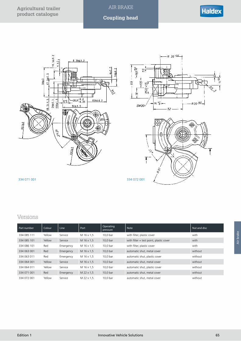
The coupling heads are installed in dual-line air brake systems for
connecting the supply and brake lines of the towing vehicle to
the trailor. The coupling heads comply with ECE/EC regulations
and ISO specifications R 1728. They can be coupled with
coupling heads corresponding to the standard SAE J 318 or VG
74342. The coupling heads are installed only on towing vehicles.
The coupling heads must be installed in accordance with the
ISO standard 1728.
Function
Stop lugs which prevent the coupling head “supply” (red cover)
being coupled with the coupling head “brake” (yellow cover)
are provided on the housing of the coupling heads. When
coupling together, the sealing ring of the mating coupling head
presses the pressure piece downwards on to the rocker valve.
The through passage at the sealing seat is opened and the
compressed air flows through the coupled connection.
Installation
The coupling head for the supply line is installed on the towing
vehicle on the right-hand side as viewed in the direction of
driving and the coupling head for the brake line to the left. The
coupling surfaces must point to the right, coupling must take
place without difficulties.
Maintenance
After uncoupling, the cover must be closed in order to prevent
dirt from entering. Damaged sealing rings must be renewed.
The coupling heads must be maintained as part of the legal
regulations.
Testing
› Check whether the coupling head engages correctly
› Ensure it does not leak
› Check sealing rings for damage
Technical data
Medium: Air
Operating pressure: see table versions
Operating temperature: -40°C to +80°C
334 08. ...
Tractor Trailer
Tractor Trailer
63Edition 1 Innovative Vehicle Solutions
Agricultural trailer product catalogue
AIR BRAKE
Coupling head
Air
bra
ke

334 086 101
334 085 111
64 Innovative Vehicle Solutions Edition 1
Agricultural trailer product catalogue
AIR BRAKE
Coupling head
334 071 001 334 072 001
Versions
Part number Colour Line Port Operating pressure Note Nut and disc
334 085 111 Yellow Service M 16 x 1,5 10,0 bar with filter, plastic cover with
334 085 101 Yellow Service M 16 x 1,5 10,0 bar with filter + test point, plastic cover with
334 086 101 Red Emergency M 16 x 1,5 10,0 bar with filter, plastic cover with
334 063 001 Red Emergency M 16 x 1,5 10,0 bar automatic shut, metal cover without
334 063 011 Red Emergency M 16 x 1,5 10,0 bar automatic shut, plastic cover without
334 064 001 Yellow Service M 16 x 1,5 10,0 bar automatic shut, metal cover without
334 064 011 Yellow Service M 16 x 1,5 10,0 bar automatic shut, plastic cover without
334 071 001 Red Emergency M 22 x 1,5 10,0 bar automatic shut, metal cover without
334 072 001 Yellow Service M 22 x 1,5 10,0 bar automatic shut, metal cover without
65Edition 1 Innovative Vehicle Solutions
Agricultural trailer product catalogue
AIR BRAKE
Coupling head
Air
bra
ke

Relay emergency valve
Use
The R.E.V. controls the dual-circuit air brake system of the trailer.
The valve complies with the requirements of EC regulations
regarding brake systems. Versions with a predominance device
can adapt the braking effect between the towing and towed
vehicle.
Function
As long as there is a pressure difference between ports 1 and
2-1, the supply air flows through power inlet 1 past the overflow
seal to port 2-1 and from here to the air tank of the trailer. At
the same time, the supply air passes through the hole in the
valve spindle and is applied in the chamber between the control
piston and valve spindle piston. When released, the inlet is
closed and the outlet opened. Air is allowed to escape from
ports 2 via the opened outlet. Air is allowed to escape from the
control port 4 via the actuation valve (trailer control valve). If the
vehicle brake system is actuated, pressure is applied to port 4 of
the emergency relay valve via the brake line. The control piston
moves downwards together with the valve spindle. The outlet
is closed and the inlet opened. The compressed air flows from
port 2-1 to the ports 2 and from here into the brake chamber of
the trailer. The pressure in ports 2 is also applied to the control
piston from below. The inlet closes and the outlet remains closed
when the pressure forces acting on the control piston have
equalized. This provides a partial braking position. Any change in
pressure at port 4 results in a corresponding change in pressure
at the ports 2.
In the full braking position, the piston spindle moves downwards
to such an extent that the outlet remains closed and the inlet
fully opened.
Air is allowed to escape from port 1 out to atmosphere by
uncoupling the coupling head ”emergency” or by disconnecting
the supply line.
Since air is also allowed to escape from the chamber between
the control piston and the valve spindle piston, the spring forces
the valve spindle downwards, the outlet is closed and the inlet
opened. The full pressure from port 2-1 is directed to the ports
2.
351 008 ...release position
Symbol
351 008 ...
66 Innovative Vehicle Solutions Edition 1
Agricultural trailer product catalogue
AIR BRAKE
Relay emergency valve

Predominance device
Emergency relay valves with a predominance device can be set
in such a way that the pressure at the ports 2 is increased with
respect to port 4 in the partial braking range from pe = 0... 1.5
bars.
Depending on the set spring force on the predominance device,
the compressed air in the ports 2 is directed via a hole under
the entire surface beneath the control piston after an increased
pressure in ports 2 has been reached and after the valve plate
of the predominance device has been raised. Only now can the
final position, i.e. closed inlet and outlet be obtained.
If the trailer vehicle is to be manoeuvred in an uncoupled condi-
tion, then the automatic release valve (if fitted) flange-mounted
on the R.E.V. must be actuated.
The port is opened between port 2-1 and the valve spindle
piston by depressing the pushbutton in the release valve.
Compressed air flows from the air tank under the valve spindle
piston and presses it upwards against the force of the spring. As
a result, the inlet is closed, the outlet opened and air is allowed
to escape from the wheel brake cylinders via the vent. A so-
called ”safety pressure” has been reached if the pressure in the
air tank is no longer adequate to force the valve spindle piston
upwards against the force of the spring. The brake can now no
longer be released with the release valve. The trailer vehicle must
once again receive a supply of compressed air by connecting the
red supply line, only now can the trailer brake be released once
again using the release valve.
The release valve automatically returns to the operating position
when the red supply line is connected. The brake can now be
applied in the trailer vehicle.
The relay emergency valve combined with the automatic release
valve is mainly used on trailers with brake systems equipped with
automatic load sensing valves.
The emergency combination relay valve with manual load valve
does not comply with EC requirement. An automatic release
valve is not required if this manual load valve is equipped with a
release setting.
Pressure in control port 4 [pe...bar]
Pressure in supply port 1 [pe...bar]
Pressureindeliveryport2
Setting range of predominancein delivery port: 0 to 0.5 bar
Example:Predominanceset to 0.3 barsee Versions
Pressureindeliveryport2
Emergency braking
Release
Charging
Functional diagrams
67Edition 1 Innovative Vehicle Solutions
Agricultural trailer product catalogue
AIR BRAKE
Relay emergency valve
Air
bra
ke

Installation
The relay emergency valve should be installed with the vent
facing downwards and with its mounting flange secured by two
bolts on the vehicle frame. The automatic release valve, Part No.
352 012 001 is flange-mounted onto the relay emergency valve
by means of two socket head cap screws M 8 x 20, Part No. 051
0109 09. An O-ring, Part No. 024 0331 09 and a sealing ring,
Par No. 025 0021 09 must be used for sealing the flange port
(refer to types for part numbers of combinations).
Care must be taken in the case of combined versions to ensure
that the actuation devices are easily accessible.
Maintenance
The relay emergency valve, together with its combinations, must
be maintained as part of legal regulations.
Testing
Ensure the function of the relay emergency valve meets the
corresponding functional diagrams.
The functionality of the automatic release valve must also be
checked, in addition to the above check for leaks. With the
vehicle stationary, and the brake system ready for operation, the
supply line to the trailer vehicle is uncoupled. The piston rods
of the brake chambers on the trailer must extend quickly. The
brake must be released when the push button of the automatic
release valve is depressed against the stop.
The push button must return to its initial position when it is in
the position for manoeuvring and air is once again allowed to
enter the supply line of the trailer.
In order to check the predominance device, apply pe 4 = 3.5 bar
at port 4 and measure the modulated pressure pe 2 at outlet
port 2. In order to adjust the predominance, allow air to escape
at port 4 to atmosphere. Using a 10 mm open-ended spanner,
loosen the locknut on the adjusting screw of the predominance
device and turn the adjusting screw with an 8 mm open-ended
spanner.
Turning in clockwise direction = Increasing the predominance
setting
Turning counter clockwise = decreasing the predominance
setting
Note the specifications of the vehicle or brake manufacturer
when adjusting the predominance.
Technical data
Operating pressure: pe = 10 bar
Operating temperature: - 40°C - + 80°C
Medium: Air
Ports: 1, 4: M 16 x 1.5
1-2, 2: M 22 x 1.5
Port description: 1 = Supply
2 = Delivery
4 = Control
2-1 = Delivery/Supply
Versions
Part number Version Flange for shunt valve Predominance set (bar) Availability
351 008 111 A yes 0,5 on request
351 008 112 A yes 0 on request
351 008 113 A yes 0,2 on request
351 008 121 B yes, but closed 0,5 on request
351 008 122 B yes, but closed 0 yes
351 008 123 B yes, but closed 0,2 on request
351 008 124 B yes, but closed 0,3 on request
351 009 121 B yes, but closed without yes
351 033 001 for EB+ no without yes
351 022 001 yes 0,2 yes
Combinations
Part number Relay emergency valve Shunt valve Manual load sensing valve Availability
350 026 102 351 008 122 352 012 001 yes
350 027 202 351 008 122 352 011 102 yes
350 028 101 351 008 122 352 012 001 352 011 122 yes
68 Innovative Vehicle Solutions Edition 1
Agricultural trailer product catalogue
AIR BRAKE
Relay emergency valve

Pressure limiting valve
Use
The pressure limiting valve limits the pressure in the brake
chambers of the trailer depending on the load status.
Function
The lever of the pressure limiting valve must be set manually,
corresponding to the Ioad status of the trailer. Depending on
the type, the settings “no-load”, “half load”, “full load”, and in
some cases “1/4 load”, “3/4 load” and “release” are provided.
When the service brake system of the trailer is actuated, the
compressed air from the relay emergency valve flows into inlet
port 1 of the pressure limiting valve and then through the open
outlet port 2 and onto the brake chambers.
At the same time, the pressure in outlet port 2 is also applied
via a hole to the control piston. When a pressure corresponding
to the lever setting has been reached in the brake cylinders, the
control piston is shifted downwards against the force of the
spring until both inlets close. The outlet remains closed. Further
increase of pressure in the brake cylinders is not possible. A drop
in pressure in outlet port 2 (e.g. as a result of a leak between
the pressure limiting valve and brake cylinder) is immediately
compensated by the control piston moving upwards and
opening the upper inlet.
The spring under the control piston is preloaded corresponding
to the lever position by means of the cam arranged on the
lever shaft. In the lever position “full load”, the control piston
is prevented from moving downwards so that the inlet remains
open and during full braking, the brake cylinders receive the full
operating pressure.
The lever must be moved into the position “release” (if provided)
in order to manoeuvre the uncoupled trailer vehicle with the
brakes applied. In this way, the spring under the control piston
is completely relieved, the inlet closed, the outlet opened and
the compressed air escapes from the brake cylinders into the
atmosphere via the vent holes in the protective cap.
In the case of versions without the “release” setting, a release
valve flange-mounted on the relay emergency valve must
be actuated for releasing the brake system for manoeuvring
purposes
352 011 ...
69Edition 1 Innovative Vehicle Solutions
Agricultural trailer product catalogue
AIR BRAKE
Pressure limiting valve
Symbol
Air
bra
ke

Installation
The pressure limiting valve can be installed either directly flanged
on the relay emergency valve (using a sealing ring Part No, 025
0021 09) or installed in the line between the relay emergency
valve and brake cylinder.
Care must be taken to ensure the lever is adequately accessible.
The vent must face downwards.
lt is recommended to install a pressure limiting valve for each
axle or axle pair if the front and rear axle(s) of the trailer are
subjected to different loads during operation. Each pressure
limiting valve then limits the brake pressure in the corresponding
axle independently of the other. The allocation of the pressure
limiting valve should be indicated by means of an information
plate.
70 Innovative Vehicle Solutions Edition 1
Agricultural trailer product catalogue
AIR BRAKE
Pressure control valve

Versions
Maintenance
The pressure limiting valve must be maintained as part of the legal regulations. Renew damaged dust caps. Pressure setting of
manual load valve. Depending on the version, the pressure setting of the pressure limiting valve can be adjusted for the settings “no
load”, “1/4 load” or “1/2 load” by turning the adjusting screws. lt is not possible to adjust the pressure for the “full load” setting.
A screwdriver DIN 911-4 (key for socket head cap screws 4 mm) is required for adjustment work. The lever position for adjusting the
pressure in “no load”, “1/2 load”, “1/4 load” and “3/4 load” setting is specified in the following.
Turning the adjusting screw in a clockwise direction = pressure reduction
Turning the adjusting screw in a counter clockwise direction = pressure increase
The pressure value to be adjusted depends on the specifications of the vehicle manufacturer.
Testing
Check pressure setting in the individual lever positions (note specifications of vehicle manufacturer). For reference values, refer to
types or information on carrying out special brake inspections. Check release position (if available). The brakes must be free in the
“release” position. Check dust cap.
Technical data
Operating pressure: up to 10 bar
Operating temperature: -40°C to +80°C
Ports: M 22 x 1.5
Port description: 1 = Supply
2 = Delivery
Part number Brake system Operating pressure pe in bar Release Empty 1/4 1/2 3/4 Load Empty 1/4 1/2
Setting at position (pe in bar) Possible pressure settings (pe in bar)
352 011 101 Single line 5,3 with 1,5 - 1,9 - 3,0 - 3,5 - Tank pressure 1,0 - 2,0 - 3,0 - 4,5
352 011 102 Dual line 7,35 with 2,0 - 2,5 - 4,0 - 4,5 - Tank pressure 1,3 - 2,5 - 3,0 - 4,5
352 011 121 Single line 5,3 without 1,5 - 1,9 - 3,0 - 3,5 - Tank pressure 1,0 - 2,0 - 3,0 - 4,5
352 011 122 Dual line 7,35 without 2,0 - 2,5 - 4,0 - 4,5 - Tank pressure 1,3 - 2,5 3,0 - 4,5
71Edition 1 Innovative Vehicle Solutions
Agricultural trailer product catalogue
AIR BRAKE
Pressure control valve
Air
bra
ke

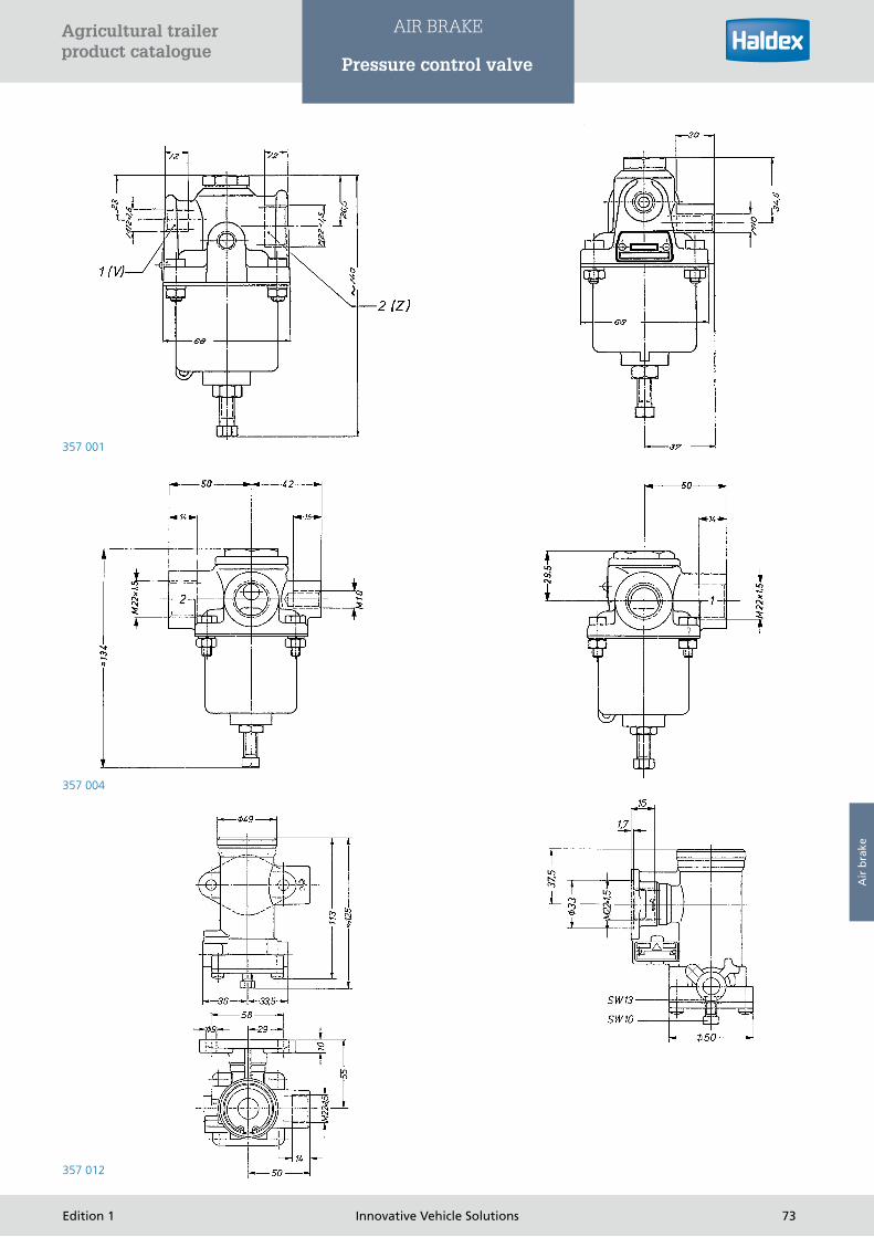
Use
In compressed air systems to limit the output pressure, but also
for changed but increased input pressure.
Function
The compressed air entering at port 1 flows over the open
valve seat to port 2, where it also acts on the spring-loaded
diaphragm.
If the set spring force is reached by the compressed air acting
on the diaphragm, the valve inlet closes so that no more
compressed air can flow to port 2. Pressure losses due to
leaks on the outlet side are automatically compensated by the
pressure limiting valve.
If the pressure are port 2 rises above the set value, the surplus
compressed air is discharged to atmosphere through the valve
outlet.
When exhausting the inlet side (port 1), the pressure opens the
outlet side (port 2) of the valve inlet. The pressure relief allows
the diaphragm to return to its initial position. Port 2 is exhausted
to port 2 via the open valve inlet.
Installation
A stub with an M 10 thread is provided for mounting. The
valve can also be installed in the piping without any particular
mounting bracket. The attitude must be selected so that the
adjuster screw points downwards.
Adjustment
The pressure can be adjusted with the adjusting screw within
certain limits after undoing the lock nut (see the table of
versions).
Rotation to the right = pressure increase
Rotation to the left = pressure decrease
Testing
Check that the pressure setting is correct (observe the vehicle
manufacturer‘s data).
Technical data
Service pressure: see the table of versions
Service temperature: -40°C to +80°C
Ports: M 22 x 1.5
Port designation: 1 = supply port
2 = delivery port
357 001 ...
357 012 ...
357 004 ...
Symbol
Versions
Part number Settable pressure (bar) Preset pressure (bar) Operating
pressure (bar)
357 001 002 0 - 1,6 0,5 8
357 004 021 0 - 7,5 6 10
357 004 024 0 - 7,5 3,5 10
357 004 025 0 - 7,5 4,5 10
357 004 051 5 - 10 5 10
357 012 021 6,5 - 8,5 7,3 12
357 012 022 6,5 - 8,5 7,5 12
357 012 031 0 - 8,5 5 12
357 012 032 0 - 8,5 6 12
72 Innovative Vehicle Solutions Edition 1
Agricultural trailer product catalogue
AIR BRAKE
Pressure control valve
357 001
357 004
357 012
73Edition 1 Innovative Vehicle Solutions
Agricultural trailer product catalogue
AIR BRAKE
Pressure control valve
Air
bra
ke

Shunt valve
Use
The special shunt valve enables the separate release of the front axle brakes (on the
turntable) of drawbar trailers in order to facilitate coupling (pivotable drawbar). The
rear axle brake remains activated during this operation.
Function
When coupling the supply line, the supply air flows to port 4 and pushes the piston
with the control button into the upper end position. Port 1 is now connected to port 2.
To disengage the front-axle brakes for re-coupling an uncoupled trailer, you must press
the activation knob into the housing.
Port 2 is now connected via Port 3 and the front-axle brakes are disengaged. The rear-
axle brakes remain activated. To re-activate the front-axle brakes after coupling, the
activation knob must be pulled out of the housing to its stop.
Port 2 is now re-charged with air by the relay emergency valve/TrCM via Port 1, which
re-activates the brakes.
Installation
Depending on the version, the device is attached to the relay emergency valve either by
two M8 screws or by flanged port. Ensure the activation knob can be accessed easily.
Testing
› Check that the valve functions correctly and is free from leaks
› When coupling the supply air, the valve must automatically switch into the filling
position (at 2.5 bar)
Technical data
Operating pressure: pe 8 bar
Operating temperature: -40°C to +80°C
Medium: Air
Changeover pressure: pe 2.5 bar
Ports: M 16 x 1.5
Port description: 11 = 1st energy inflow
12 = 2nd energy inflow
2 = energy outflow
Symbols
352 005 401
Part number Boot Exhaust valve Colour of knob Attachment
352 005 401 with with black with 2 screws M8
352 007 401 with with black flange for relay emergency valve
Versions
74 Innovative Vehicle Solutions Edition 1
Agricultural trailer product catalogue
AIR BRAKE
Shunt valve

Use
The automatic shunt valve, also known as the release valve, is
used to release the trailer brakes when uncoupled if there is no
shunt valve flanged to the relay emergency valve.
Function
When the supply line is coupled, supply air flows through
port 11 and if the valve has been previously actuated, presses
the piston with the switching knob screwed on to it into its top
end position. The supply air can then flow from port 11 to port 2
and from there to the trailer brake control valve, which releases
the brake. The compressed air flows from the tank to port 12
through a connecting line.
If the brake has to be released for manoeuvring purposes after
uncoupling the trailer, the actuator knob must be pressed into
the body.
If the brake needs to be re-actuated after manoeuvring, the
actuator knob must be pulled out of the body as far as it will go.
Port 2 is then exhausted again through port 11 and the coupling
head supply, and the Relay Emergency Valve initiates braking
again.
Installation
Mounted with SW 27 or 32 union nuts in a hole for M 22 x 1.5.
Tightening torque: 40 - 50 Nm. When removing/mounting the
actuator knob, secure the actuator rod with a suitable means.
Make sure that the actuator knob can move freely.
Symbols
352 018 ...
75Edition 1 Innovative Vehicle Solutions
Agricultural trailer product catalogue
AIR BRAKE
Shunt valve
Air
bra
ke

Testing
› Test the valve for operation and leaks
› When the supply line is connected, the valve must automatically switch to the filling position (at pe 2.5 bar)
Technical data
Service pressure: pe 8 bar
Service temperature: -40 °C to +80°C
Medium: air
Switching pressure: pe 2.5 bar
Ports: M 16 x 1.5
Port designation: 11 = 1. supply port
12 = 2. supply port
2 = delivery port
Part number Boot Exhaust valve Plate Colour of knob Nut
352 018 001 with-
out
without with blue SW 27
352 018 011 with without with blue SW 32
352 018 021 with without without black (BW) SW 32
352 018 031 with with without black (BW) SW 32
Versions
76 Innovative Vehicle Solutions Edition 1
Agricultural trailer product catalogue
AIR BRAKE
Park and shunt valve

Park and shunt valve
Use
The park and shunt valve is used to actuate and release the
spring brakes (park), and also release the automatic emergency
braking (shunt), on uncoupled trailers.
Function
352 044/045 ...
Vehicle uncoupled, black knob pulled out, red knob pressed in.
System pressure is present at port 11. Port 21 is exhausted via
the supply coupling head. The service brake has been put into
the emergency braking position by the Relay Emergency Valve/
emergency brake valve. Port 22 is charged with air (spring brakes
released).
When the shunt valve (black knob) is pushed in, port 11 is
connected to port 21 (service brake released). The service brake
is actuated again by pulling out the shunt valve (black knob).
When the parking valve is pulled out (red knob), port 22 is
exhausted. The spring brake is not exhausted (immobilised) until
the two-way valve in the system reverses.
352 046 ...
(emergency braking using the spring brakes)
Vehicle uncoupled, black knob pulled out, red knob pressed in.
System pressure is present at port 11. Port 22 is exhausted via
the supply coupling head (spring brakes immobilised). When the
shunt valve (black knob) is pushed in, port 11 is connected to
port 22 (spring brakes released).
028 0383 09 instruction plate
352 044 ... 352 045 ... 352 046 ...
Symbol
352 04. ...
Part number Single check valve
Integrated emergency brake function
Instruction plate 028 0383 09
352 044 001 withoutNo, relay emergency valve
required with
352 044 011 withoutNo, relay emergency valve
required without
352 045 001 Port 11No, relay emergency valve
required with
352 045 011 Port 11No, relay emergency valve
required without
352 046 001 for park valve Yes, via spring brakes with
Versions
77Edition 1 Innovative Vehicle Solutions
Agricultural trailer product catalogue
AIR BRAKE
Park and shunt valve
Air
bra
ke

352 046 ...
352 044 ... / 352 045...
Installation
The combined park and shunt valve should be mounted on the
vehicle frame with its mounting flange, using two M8 bolts.
Actuator knobs between horizontal and 90° upwards. When
painting, protect against the ingress of paint.
Testing
Check the combined park and shunt valve for operation and
leaks.
Technical data
Service pressure: pe = 8.5 bar
Service temperature: -40°C to +80°C
Tightening torque: 34 Nm
Medium: air
Ports: 1, 11, 21, 22: M 16 x 1.5
Port designation: 2 = supply port
11 = 1. supply port
21 = 1. delivery port
22 = 2. delivery port
78 Innovative Vehicle Solutions Edition 1
Agricultural trailer product catalogue
AIR BRAKE
Park and shunt valve

Relay valve
Use
By installing a relay valve, air can enter and escape in large vol-
umes quickly and proportionally. It therefore serves the purpose
of shortening the response and threshold times in air brake
systems.
Function
If compressed air is applied at Control Port 4, the control piston
moves downwards, the outlet is closed, the inlet opened and
the Reservoir pressure at Port 1 is directed to the Delivery Port 2
corresponding to the control pressure.
The inlet is closed and the outlet remains closed when the
pressure at the Port 2 (this pressure is also applied to the
underside of control piston) is equal to the pressure at Port 4. A
termination setting is provided. Each change in pressure at Port
4 results in a change in pressure at Port 2.
lf air is allowed to escape at Port 4, then the inlet is closed, the
outlet opened and air escapes from Port 2 via Exhaust Port 3.
Symbols
355 018 ... / 355 093 ...
3
Installation
The stud bolts provided are used for mounting the valve. The
vent must face downwards.
Testing
If defects are found during brake tests, brake inspections or
when driving, the relay valve must be thoroughly inspected and
replaced if necessary. Checking check function and for leaks.
355 018 ...
79Edition 1 Innovative Vehicle Solutions
Agricultural trailer product catalogue
AIR BRAKE
Relay valve
Air
bra
ke
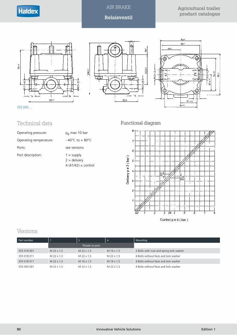
355 093 ...
Versions
Technical data
Operating pressure: pe max 10 bar
Operating temperature: - 40°C to + 80°C
Ports: see versions
Port description: 1 = supply
2 = delivery
4 (41/42) = control
Part number 1 2 4 Mounting
Threads on ports
355 018 001 M 22 x 1,5 M 22 x 1,5 M 16 x 1,5 2 Bolts with nuts and spring lock washer
355 018 011 M 22 x 1,5 M 22 x 1,5 M 22 x 1,5 4 Bolts without Nuts and lock washer
355 018 071 M 22 x 1,5 M 16 x 1,5 M 16 x 1,5 4 Bolts without Nuts and lock washer
355 093 001 M 22 x 1,5 M 22 x 1,5 M 22 x 1,5 4 Bolts without Nuts and lock washer
Functional diagram
80 Innovative Vehicle Solutions Edition 1
Agricultural trailer product catalogue
AIR BRAKE
Relaisventil

Quick release valve
Use
Air can be quickly exhausted by fitting a quick release valve.
The top port is connected to the actuator valve, and the side
ports to the brake chambers. Another typical application is to
use as a dump valve in air suspension systems, e.g. with tipper
vehicles (only 356 001 011).
Function
When air is applied to the top port, the outer edge of the
diaphragm folds over and compressed air flows to the side ports.
If the application of air through the top port is interrupted by the
actuator valve, the volume from the actuator valve to above the
diaphragm is exhausted via the actuator valve. The compressed
air from the brake chambers passes through the side ports and
pushes the outer edge of the diaphragm against the seat and
lifts the inner seat. The volume from the brake chambers to
under the diaphragm is exhausted via the quick-release valve.
Installation
The quick-release valve should be installed directly in the piping
near the brake chamber, with the exhaust port pointing down-
wards. A filter, or in the case of vehicles with a fording capability
a snorkel, can be screwed into the exhaust port if desired.
A bracket with two M10 holes is provided on the quick-release
valve for mounting it on the vehicle.
Note that on 350 036/037 the holes in the two-way valve must
not be used for mounting.
Testing
› Check that the stepped variability of the actuator valve is not
adversely affected when the quick-release valve is actuated
› Test the operation of the quick-release valve
Technical data
Service pressure: 10.5 bar
Service temperature: -40°C to +80°C
Ports: see the table of versions
Port designation: 2 = supply port
11 = 1. supply port
12 = 2. supply port
2 = delivery port
3 = exhaust
356 001 ... 356 022 ...
Functional diagram
81Edition 1 Innovative Vehicle Solutions
Agricultural trailer product catalogue
AIR BRAKE
Quick release valve
Air
bra
ke

Combinations of quick release valve and two-way valve
Versions
Part number 1 2 3 Note
356 001 001 M 22 x 1,5 M 22 x 1,5 M 22 x 1,5 -
356 001 011 M 22 x 1,5 M 22 x 1,5 M 22 x 1,5 with reinforced diaphragm
356 006 011 M 22 x 1,5 M 22 x 1,5 without thread
356 022 001 M 22 x 1,5 4 x M 16 x 1,5 without thread -
356 022 011 M 22 x 1,5 4 x M 16 x 1,5 M 22 x 1,5 -
356 022 021 1/2“ -14NPTF 4 x 1/4“ -18 NPTF without thread -
356 022 031 M 22 x 1,5 4 x M 16 x 1,5 M 22 x 1,5 -
356 023 001 M 22 x 1,5 2 x M 16 x 1,5 without thread -
356 023 011 M 22 x 1,5 2 x M 16 x 1,5 M 22 x 1,5 -
356 023 021 1/2“ -14NPTF 2 x 1/4“ -18 NPTF without thread -
356 023 031 M 22 x 1,5 2 x M 16 x 1,5 M 22 x 1,5 -
Part number 11 + 12 2 3
Threads on ports
350 036 201 M 16 x 1,5 4 x M 16 x 1,5 without thread
350 036 211 M 16 x 1,5 4 x M 16 x 1,5 M 22 x 1,5
350 037 201 M 22 x 1,5 2 x M 16 x 1,5 without thread
350 037 211 M 22 x 1,5 2 x M 16 x 1,5 M 22 x 1,5
82 Innovative Vehicle Solutions Edition 1
Agricultural trailer product catalogue
AIR BRAKE
Quick release valve

356 001
356 022
356 006 011
83Edition 1 Innovative Vehicle Solutions
Agricultural trailer product catalogue
AIR BRAKE
Quick release valve
Air
bra
ke
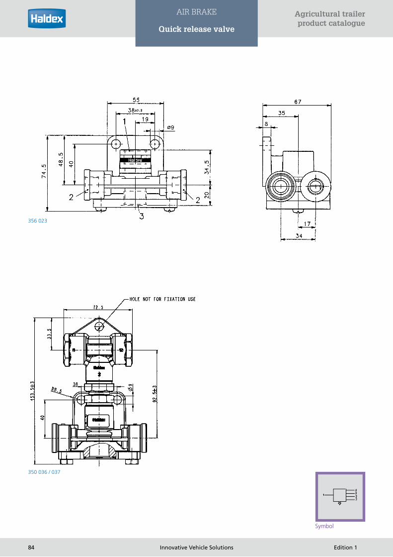
356 023
350 036 / 037
Symbol
84 Innovative Vehicle Solutions Edition 1
Agricultural trailer product catalogue
AIR BRAKE
Quick release valve

Regulating valve
Use
During the braking procedure, a dynamic axle load displacement
occurs, i.e. the rear axle is relieved, and the front axle is addition-
ally loaded. For this reason, larger air brake chambers are gener-
ally installed on the front axle. In the partial braking range, i.e. at
low dynamic axle load displacement, a built-in pressure regula-
ting valve (with kinked characteristic curve) reduces the pressure
in the large air brake chambers enabling, in this way, matching
of the brake forces between the individual axles of the vehicle. A
quick release effect is also provided.
The pressure regulating valve has a 1:1 pressure advance control
up to approx. 0.5 bar in order to facilitate overcoming the re-
sponse stages of the brakes and of any subsequently connected
valves. The pressure is reduced from applied pressures 0.5 bar
onwards.
Function
Port 1 is connected to the actuation valve, the ports 2 are linked
to the brake chamber. When air is allowed to enter port 1,
initially the compressed air flows in unreduced through ports
2 to the brake chambers. The balance piston moves upwards
when a pressure pe2 > 0.5 is reached on the underside of the
piston. The inlet seat is closed as soon as the ratio of applied to
modulated pressure corresponds to the area ratio (underside/
top side) of the balance piston. The pressure at port 2 is
therefore reduced corresponding to the surface area ratio of
the balance piston (phase 1 in functional diagram). The piston
is raised from its seat against the force of the spring when the
applied pressure pe 1 has reached the value of the “kink” in the
functional diagram. Compressed air can now be applied to the
upper annular surface of the balance piston via the bore holes.
This means that the pressure-loaded areas of the upper and
Iower side of the balance piston are equal. As a result, the rate
of pressure reduction is reduced and completely stopped at an
applied pressure pe 1 = 3.0 ± 0.2 bar (356 005 101) or 4.0 ± 0.2
bar (356 005 102), (pEnd) (phase II in functional diagram).
lf the pressure drops at port 1, the balance piston is pressed
upwards, the inlet seat is closed, the outlet seat opened and
air is allowed to escape from the brake chambers connected to
ports 2.
Adjusting the pressure adaptation (pEnd)
The adjusting screw can be turned after releasing the counter
nut
› In clockwise direction - retarded pressure matching (pEnd)
› In anti-clockwise direction - advanced pressure matching
(pEnd)
356 005 ...
Functional diagram
85Edition 1 Innovative Vehicle Solutions
Agricultural trailer product catalogue
AIR BRAKE
Regulating valve
Symbol
Air
bra
ke

Installation
Normally the pressure regulating valve is installed before the
large brake chambers.
The vent must face downwards and the screw for adjusting
the pressure balance must be easily accessible.
The valve is mounted by means of two M8 screws in the
threaded holes M8.
Adjusting the adaptation pressure pEndThe adaptation pressure pEnd must always be adjusted in
accordance with the manufacturer’s specifications for
the relevant vehicle or trailer (e.g. brake calculation).
After releasing the locknut, the adaptation pressure pEnd can be
adjusted from 0 to approx. 4.0 bar.
Tightening the adjustment screw
Increasing the adaptation pressure and pressure reduction; pEnd
max. approx. 4.0 bar.
Loosening the adjustment screw
Decreasing the adaptation pressure and pressure reduction. After
adjustment with the locknut, re-tighten and mark the position of
the adjustment screw.
(Recommendation: Secure with shrink tube or mark
with a coloured dot.)
Testing
› Testing that device functions correctly and is free from leaks
› Adaptation pressure pEnd in accordance with vehicle/trailer
manufacturer’s specifications
Technical data
Operating pressure: max. 8 bar
Operating temperature: -40°C to +80°C
Adaptation pressure pEnd: 0-4.0 bar
Ports: 1, 2: M 22 X 1.5
Port description: 1 = Supply
2 = Delivery
Part number Pressure alignment at … bar
356 005 101 3,0
356 005 102 4,0
356 005 103 2,5
356 005 104 3,5
Versions
86 Innovative Vehicle Solutions Edition 1
Agricultural trailer product catalogue
AIR BRAKE
Regulating valve

Use
During the braking procedure, a dynamic axle load displacement
occurs, i.e. the rear axle is relieved, and the front axle is
additionally loaded. For this reason, large brake chambers are
normally installed on the front axle.
In the partial braking range, i.e. at low dynamic axle Ioad
displacement, a built-in pressure regulating valve (with straight
characteristic curve) reduces the pressure in the large brake
chambers, thereby making it possible to adapt the brake forces
between the individual axles of the vehicle. The valve also
features a quick release effect.
Function
Port 1 is connected to the actuating valve; port 2 is linked to the
brake chambers.
When air is allowed to enter at port 1, the diaphragm and
the piston are pressed downwards against the force of the
preloaded compression spring when a set opening pressure has
been reached.
The outlet seat is closed and the inlet seat opened. The
compressed air flows through port 2 to the brake chambers.
The applied pressure pe1 (pe1 = pe2) is no longer reduced when
the set adaptation pressure (pEnd) is reached.
Installation
The installation site should always be selected in accordance
with the valve sequence, which is a constituent part of the brake
calculation of each vehicle. In case of doubt, consult the vehicle
manufacturer. The regulating valve is generally installed before
the larger brake chambers.
The adjustment screw and the exhaust must point down.
Any test point must be easily accessible for measuring the
pressure (depending on the version).
The device is attached to whatever type of console is present in
the particular version either with the two M6 screws provided
or with two additional M8 screws, especially if the valves are
attached to the ports 2 with flexible lines.
The exhaust must not be covered with paint when painting the
vehicle.
Depending on the version, the device has been factory set
to a particular adaptation pressure pEnd. After completion
of installation, check whether the equalisation pressure
pEnd corresponds to the manufacturer’s specifications (brake
calculation).
Symbol
356 009 ... / 356 010 ...
Functional diagram
87Edition 1 Innovative Vehicle Solutions
Agricultural trailer product catalogue
AIR BRAKE
Regulating valve
Air
bra
ke

Adjusting the equalisation pressure (pEnd)
The equalisation pressure pEnd must always be adjusted in
accordance with the manufacturer’s specifications for the
relevant vehicle or trailer (e.g. brake calculation).
After releasing the locknut, the equalisation pressure pEnd can
be adjusted from 0 to approx. 5.5 bar.
Tightening the adjustment screw
Increasing the equalisation pressure and pressure reduction;
pEnd max. approx. 5.5 bar.
Loosening the adjustment screw
Decrease the equalisation pressure and pressure reduction; pEnd
min. 0 bar.
The adjustment screw must never be loosened to its limit,
because this can block the flow from Port 1 to Port 2.
After adjustment, re-tighten the locknut.
Testing
› Test that device functions correctly and is leak tight
› Equalisation pressure pEnd in accordance with vehicle/trailer
manufacturer’s specifications
Technical data
Operating pressure: max. 8 bar
Operating temperature: -40°C to +80°C
Adaptation pressure pEnd: 0-4.0 bar
Ports: 1, 2: M 22 X 1.5
Port description: 1 = Supply
2 = Delivery
Version A
Version B
Version C
Part number Version Opening pressure (bar) Adaptation at … bar Bracket Test point
356 009 011 A 0,5 2,0 Yes No
356 009 012 A 0,3 1,3 Yes No
356 010 011 B 0,8 3,5 Yes Yes
356 010 031 B/C 0,8 3,5 Yes Yes
Versions
88 Innovative Vehicle Solutions Edition 1
Agricultural trailer product catalogue
AIR BRAKE
Regulating valve

Mechanical load sensing valve
Use
The load sensing valve (L.S.V.) serves the purpose of
automatically adapting the brake pressure and therefore the
brake force according to the load of the vehicle.
Automatic load-dependent brake force regulation is compulsory
for semi trailer tractors with a permissible total weight of more
than 7.5 t and semi-trailers with the sum of the permissible axle
loads greater than 7.5 t when the vehicle was registered for the
first time from 1st January 1963.
EC regulations (RKEG 74/132 EWG) as well as the ECE
stipulation No. 13 specify automatic brake force regulation for
all motor vehicles and trailers with a total weight exceeding 3.5 t
provided brake force regulation is necessary.
Function
lf the load of the vehicle is changed, then as a result, the
deflection of the vehicle springs also changes. While loading the
vehicle, the vehicle body approaches the axles, when unloading
the distance between the vehicle body and the axle becomes
greater. The travel of the vehicle body can be used for controlling
the load sensing valve. The load sensing valve is mounted to the
chassis of the vehicle, the control cable together with the spring
is mounted an a bracket bolted or welded to the axle.
The control cable is secured to the control lever of the load
sensing valve by means of a clamp. When unloading the
vehicle, the tension spring pulls the control lever downwards
601 002 001
601 002 ... / 601 013 ...
89Edition 1 Innovative Vehicle Solutions
Agricultural trailer product catalogue
AIR BRAKE
Mechanical load sensing valve
Symbol
Air
bra
ke

over the cable. When the vehicle is loaded, the control lever
is raised by a spiral spring until the control cable is tensioned.
The shock absorber mounted on the control lever, together
with the tension spring, takes up the dynamic impact caused
by unevenness in the road. The load sensing valve operates
statically, i.e. changes in the spring path which occur during
braking do not change the control ratio. The load sensing valve
is slightly locked during braking.
Release Position, Half Load
The brake piston moving in the upper part of the housing
is connected to the valve sleeve by means of the piston rod
on which the double valve cone is mounted in a floating
arrangement. The valve sleeve guides the balance spring. The
locating pin supported by a compression spring on the housing
is connected to the thrust piece by means of the balance lever
and the variable slide piece.
A change in movement downwards or upwards executed by the
control lever results in the slide piece being shifted and therefore
changes the effective transmission ratio between the brake
piston and balance piston.
The ratio of the pistons and balance lever is set in such a
way that, in setting “load”, the pressure applied at port 1 is
modulated at port 2 uncontrolled, i.e. control ratio pe1/pe2 =
1:1. In the position “no-load”, the applied pressure pe1 can be
reduced in a control ratio of 6:1 with respect to the modulated
pressure pe2. Each control ratio between “no-load” and “load”
is continuously variable. In the release position, the double valve
cone closes
the inlet seat; port 2 is connected to atmosphere via the open
outlet seat.
Brake Setting, Half Load
When the brake is actuated, compressed air flows through port
1 and presses the brake piston upwards while the valve sleeve
is pressed against the double valve cone. The outlet seat is now
closed, the inlet seat opened. The compressed air now flows to
port 2 and is applied to the balance piston. The force acting on
the balance piston is transmitted via the thrust piece and the
balance levers to the brake piston thereby moving it downwards.
The inlet seat is closed, the outlet seat remains closed. A so-
called partial braking setting is obtained.
Each change in pressure at port 1 results in a change in pressure
at port 2 corresponding to the set control ratio.
The brake piston moves back into its initial position if air is
allowed to escape at port 1. Air escapes via port 2 via the now
open outlet seat and the vent valve on the housing. 601 002 021
Control cable
003 0386 09 with disc
90 Innovative Vehicle Solutions Edition 1
Agricultural trailer product catalogue
AIR BRAKE
Mechanical load sensing valve

The load sensing valve has a proportional characteristic equipped
with a pressure advance control of pe = 0.3 ... 0.4 bar for
overcoming in the response stages of subsequently connected
brake devices.
In the event of the control cable breaking, the control lever is
raised to the position “load” by the shock absorber or spiral
spring. The pressure applied at port 1 is directed to port 2
uncontrolled.
Brake setting, loading
The transmission of the pistons and weighing lever must be
arranged in such a way that, when in the “loading” position,
the pressure introduced in Port 1 pe1 is controlled without
regulation – i.e. the regulating ratio pe 1/pe 2 = 1:1 –
from Port 2.
Installation
The load sensing valve regulator is attached with screws, nuts
and washers to the attachment holes that are drilled into the
assembly.
Attaching the control cable
The control cable’s spring is attached via an M12 Allen bolt to
the bracket that is fitted to the axle. The bracket should be at
least 8 mm thick. If the bracket is welded in place, authorisation
must be sought from the manufacturer for this. The welded
seams must always be in the neutral zone. Attach the control
cable with a cable clamp in the “Empty” control lever position at
the calculated interval (lever length) from the pivot of the control
lever (torque for control screw: 6 Nm). In order to balance the
settling of the vehicle springs, the supplied 5 mm thick disc
should be fitted underneath the control spring of the control
cable. If the vehicle spring has settled by approx. 5 mm, this
disc is removed. Further adjustment can be made by moving the
control cable in the clamp.
In order to avoid damage or excessive wear on the linkage
components, the following points must be noted when installing
the cable link:
› The control cable should be as long as possible
› The control cable should be within the lever’s level of
movement.
› Ensure all parts can move easily
› Attach the control cable as close as possible to perpendicular
from the control lever on the bracket
The control cable is attached to the control lever or the load
sensing valve regulator with a different linkage component for 601 013 001 - 011
91Edition 1 Innovative Vehicle Solutions
Agricultural trailer product catalogue
AIR BRAKE
Mechanical load sensing valve
Air
bra
ke

each version. When unloading the vehicle, the control springs
pull the control lever downwards via the cable. If the vehicle is
loaded, the control lever is lifted by a leg spring until the control
cable is tensioned. Linking the cable and spring enables the
spring deflection to be tapped from an axle even with twin-axle
assemblies.
Example
Control ratio i R = 3:1
Control path fs = 30 mm
Derived from nomogram: lever length L = 52 mm
The unladen braking pressure must be adjusted after installing
the load sensing valve on the vehicle.
The adjustment procedure is described in the following:
› Press control lever downwards as far as it will go.
› Apply a pressure pe1 = 6.0 bar to port 1, measure the
modulated pressure pe2 from port 2.
Raise the control lever in stages - after venting pe1 each time -
until the required unladen braking pressure pe2 is obtained for
pe1 = 6.0 bar.
› Hold control, lever in this position, screw in stop screw
(M 6, 10 mm) until a resistance can be felt and tighten
counter locknut.
Mounting the control cable: the spring of the control cable
is secured by means of a hexagon bolt M 12 to the bracket
mounted on the axle. The minimum thickness of the bracket
should be 8 mm. If the bracket is welded, then permission must
be obtained from the axle manufacturer for this purpose. The
weld seams must always be in the neutral zone. With the control
lever in unladen position, move the control cable together with
the clip into the position (see 3.) at a determined distance (lever
length) from the pivot point of the control lever (tightening
torque of clamping screw 6 Nm).
A 5 mm thick washer is provided under the tension spring of the
control cable in order to balance out the setting of the vehicle
springs. This washer is removed when the vehicle spring has set
by approx. 5 mm. Further readjustment is possible by moving the
control cable in the clamp.
Alignment chart for ALB
601 002 ...
601 013 ...
92 Innovative Vehicle Solutions Edition 1
Agricultural trailer product catalogue
AIR BRAKE
Mechanical load sensing valve

This cable and spring arrangement makes it possible to measure
the spring path of one axle even in the case of double axle units.
In order to avoid damage or excessive wear of the link parts, the
following points must be observed when installing the cable link:
› a) The control cable must be as long as possible.
› b) The control cable must be located within the moving plane
of the lever.
› c) Ensure all parts move freely.
› d) Arrange control cable on the bracket as close to the vertical
as possible with respect to the control lever.
Checking the modulated brake pressure in the control lever
position “Ioad“:
Remove hexagon screw M 12 (for holding the control cable to
the bracket).
The control lever or control cable moves upwards by the amount
of the spring travel.
Apply 6.0 bar at port 1 and you should see 6.0 bar at port 2.
The technical data information is stamped on the separately
supplied information plate, part No. 028 0216 09.
The information plate must be arranged securely and clearly
visible in the vicinity of the vehicle chassis I.D. plate, i.e. on the
front left of the vehicle viewed in the direction of travel.
Basic adjustment necessary when the values specified in point 3
and point 5 are not obtained.
The Ioad sensing valve is adjusted at the manufacturer so that
At 6.0 bar input pressure at port 1 and with the control lever in
the laden position
› 6.0 bar output pressure is obtained at port 2 (control ratio
pe1/pe2 = 1:1)
› At 6.0 bar input pressure at port 1 and the control lever in the
unladen position a 1.0 bar = + 0.3 bar pressure is obtained at
port 2 (control ratio pe1/pe2 = 6:1).
This adjustment must not be changed.
However, basic adjustment is necessary if this setting has
been changed.
Basic adjustment of the load sensing
valve
› The control lever must be in the laden position as the result of
the automatic return.
› Remove the rubber cap on the housing.
› Using screwdriver DIN 911-5 turn the screw for fine
adjustment (on slide piece) as far as it will go in a clockwise
direction.
› Apply a pressure of 6.0 bar at port 1 and measure the
modulated pressure at port 2. If the basic adjustment is
correct, pe2 must be equal to pe1. If this is not the case, the
difference between pe1 and pe2 must be adjusted until equal.
› Allow air to escape at port 1 and turn fine adjustment screw
in an anticlockwise direction.
The number of turns equals the difference determined in (d)
multiplied by 10.
Example
› pe1 = 6.0 bar
pe2 = 5.7 bar
(d) = pe1 - pe2 = 6.0 bar - 5.7 bar = 0.3 bar
0.3 bars x 10 = 3 turn.
› Attach rubber cap to housing.
› Apply 6.0 bar at port 1, measure pressure at port 2.
it should now equal Port 1
› Vent port 1, press control lever downwards as far as it will go.
› Apply 6.0 bar at port 1, the pressure at port 2 must equal 1.0
+ 0.3 bar,
If the value at port 2 is not obtained, release the counter nut of
the stop screw and vary the screw-in depth of the stop screw
so that at a pressure of 6.0 bar applied at port 1 and with the
control lever in the unladen position, a pressure of 1.0 bar + 0.3
bar is obtained at port 2.
Technical Data
Operating pressure: max 10 bar
Operating temperature: -40°C to +80°C
Ports 1, 2: M 16 X 1.5
Port description: 1 = Supply in
2 = Delivery out
93Edition 1 Innovative Vehicle Solutions
Agricultural trailer product catalogue
AIR BRAKE
Mechanical load sensing valve
Air
bra
ke

003 0380 09
Maximum mounting length: 1045 mm
Minimum mounting length: 140 mm + maximum deflection
003 0386 09
Maximum mounting length: 1025 mm
Minimum mounting length: 120 mm + maximum deflection
003 6340 09
Maximum mounting length: 985 mm
Minimum mounting length: 100 mm + maximum deflection
Part number Shock absorber Cable Washer poss lever length maximum deflection of the spring smallest +maximum deflection maximum
Mounting height
601 002 001 Yes 003 0380 09 no 90 - 176 mm 135 mm 140 mm 1045 mm
601 002 021 no 003 0386 09 Yes 25 - 50 mm 108 mm 120 mm 1025 mm
601 002 031 Yes 003 6340 09 no 90 - 176 mm 60 mm 100 mm 985 mm
601 002 071 no 003 6340 09 Yes 25 - 50 mm 60mm 100 mm 985 mm
601 013 001 no 003 0386 09 Yes 50 - 130 mm 108 mm 120 mm 1025 mm
601 013 011 no 003 0386 09 Yes 50 - 130 mm 108 mm 120 mm 1025 mm
601 013 041 no 003 6340 09 Yes 50- 130 mm 60 mm 100 mm 985 mm
Versions
94 Innovative Vehicle Solutions Edition 1
Agricultural trailer product catalogue
AIR BRAKE
Mechanical load sensing valve

Pneumatic load sensing valve
Use
The automatic load sensing valve ( LSV )–pneumatically
controlled, is installed in vehicles ( motor vehicles, trailers
and articulated trailers ) with pneumatic braking systems and
pneumatic suspensions. The braking pressure in the pneumatic
braking system, and with that the braking force, is controlled to
correspond to the static load condition of the particular vehicle.
When the static load changes, the pressure in the suspension
bellows changes continuously via the pneumatic suspension
valve. This pressure is used to simultaneously control the
connections 41, 42 of the LSV.
The effective, easily reconstructed in the workshop, pressure
ratio iR = pe1: pe2 is the practical reference point for the
adjustments.
Function
The connectors 41, 42 of the actuating cylinder are attached to
the connecting lines of the pneumatic suspension valves/bellows
on the right and left sides of the vehicle.
The pistons in the actuating cylinder are held in the end
position when the vehicle is empty (suspension pressure empty
connections 41, 42).
When the vehicle is loaded and the pressure rises at the
connections 41, 42, the control pistons and the slider (1)
attached to them by the connecting rod are shifted to the right
which results in a change in the effective movement translation
ratio.
The translation movement between the pistons and balance
arm is so adjusted that with suspension pressure empty the
control inlet brake pressure pe1 at connection 1 is transferred
to the outlet control pressure at connection 2 but reduced by
the pressure ratio iR. The system is normally designed so that in
the loaded position the controlled inlet pressure in connection
1 remains unmodified, i.e. the controlled outlet pressure at
connection 2 is in 1:1 relation to it.
The LSV is fitted with a proportional control characteristic
that has a start pressure control (pD) of approx. 0.4 bar in the
uncontrolled range to overcome the start force (valves, wheel
brakes)
The LSV works “statically”, i.e. a change in the pressure ratio,
e.g. from a change in suspension pressure following a change in
axle loading, is suppressed during braking.
Symbol
602 005 ...
Input pressure pe1 (bar)
Del
iver
y pr
essu
re p
e2 (
bar)
Functional diagram
95Edition 1 Innovative Vehicle Solutions
Agricultural trailer product catalogue
AIR BRAKE
Pneumatic load sensing valve
Air
bra
ke

Setting instructions
The LSV is not set up in the factory with any particular
suspension or brake pressures so these must be set by the vehicle
manufacturer to the necessary values (LSV instruction plate).
The setting ( diagram or LSV setting program) is made in a
mechanical part and a pneumatic part.
Mechanical part
Setting the pivot point (X)
1. Determine the actuating cylinder travel with the help of the
diagram
2. Calculate the intermediate value with the formula
3. Determine pivot position (X) for the balance arm from the
pivot scale :
Rigid bearing
Pivot point
Balance arm
Supply pressure pe1 (bar)
Control cylinder stroke (mm)
deliv
ery
pres
sure
pe2
(ba
r)
Diagram
Scale for pivot point
Formula for intermediate value:
(Bagpressure laden - bagpressure unladen) x 36
Control cylinder stroke
Example
(5 - 1,5) x 36
24,5
intermediate value = 5,14
Pivot point = 30
96 Innovative Vehicle Solutions Edition 1
Agricultural trailer product catalogue
AIR BRAKE
Pneumatic load sensing valve

Example
› pe1 = 6.0 bar pe2 empty = 2.0 bar. With curve pe1 = 6.0 bar,
the intersection point with pe2 = 2.0 bar is formed, connect
the intersection point with the actuating cylinder scale, giving
24.5 mm actuating cylinder travel
› Suspension pressure loaded pe41, 42 = 5.0 bar, suspension
pressure empty pe41, 42 = 1.5 bar, gives 5.14 intermediate
value
› Vertically above the value of the calculated intermediate point,
the pivot position (X) can be read off the pivot scale for the
balance arm, giving 30 mm pivot point.
› Set the pivot point (X) corresponding to the value determined:
Remove cover G, hold both of the nuts between the balance
lever and the frame with the hexagonal spanner 14 mm,
loosen the locknuts on the balance lever and fixed bearing
with the hexagonal spanner 17 mm and set the pivot position
to the calculated value X. First tighten the nuts on the fixed
bearing, set up the balance arm (centrally between the return
springs for the 90° - position to the long axis of the LSV; if
necessary, remove any pre-tensioning in the return springs by
turning the adjustment screw F to the left), tighten the nuts
17 mm on the balance lever with about 12-13 Nm torque.
Pneumatic part
Setting the outlet pressure pe2 empty:
› Vent connections 1, 41, 42 to pe = 0 bar.
› Remove the rubber cap A.
› Place the hexagonal key 5 mm into screw B, shift the slider C
against the force of the spring and see whether the automatic
return takes place. If it does not return: remove bellows D,
loosen locknut E, pre-tension the springs using screw F till the
slider C returns to the starting position.
› Turn the screw B so that when controlling the inlet brake
pressure pe1 at Port 1, the desired outlet pressure pe2 empty
is controlled at Port 2. Port 1 has to be vented to pe1 = 0 bar
before the screw B is adjusted.
Turn to the left at B raises pe2
Turn to the right at B lowers pe2
› Vent Port 1 to pe1 = 0 bar. Control suspension pressure to
pe41, 42 empty in actuating cylinder.
› Control brake pressure pe1 at Port 1, the outlet pressure
pe2 empty must correspond to the previously set value. If
the outlet pressure pe2 empty is greater; again tension the
return spring in the actuating cylinder using screw F till, when
controlling pe1, the desired outlet pressure pe2 empty is
achieved ( do not tension too much ).
› Vent Port 1 to pe1 = 0 bar, raise suspension pressure pe41,
42 empty by approx. 0.7 bar, control brake pressure pe1 at
Port 1, the pressure controlled at Port 2 must now be very
slightly greater than pe2 empty. If a higher pressure is not
achieved then the pretension of the return spring is too great.
To correct this, loosen the adjustment screw F till the desired
change in outlet pressure is obtained (do not lower the spring
tension too much, examine pe2 empty again as a check),
tighten locknut E.
› Replace rubber cap A and bellows D as well as protective
cover G. Check outlet pressure pe2 loaded:
› Control the suspension pressure in the actuator cylinder to
pe41, 42 loaded, control the brake pressure pe1 at Port 1, the
outlet pressure pe2 must correspond to the value on the LSV
instruction plate, the brake calculation or the value given by
the vehicle or axle manufacturer, usually pe1 = pe2.
Mid
dle
posi
tion
Elongated hole of thecontrol lever and theelongated hole of thehousing should be here straight in line.
Balance level correct in the fix the middle position
Return spring
97Edition 1 Innovative Vehicle Solutions
Agricultural trailer product catalogue
AIR BRAKE
Pneumatic load sensing valve
Air
bra
ke
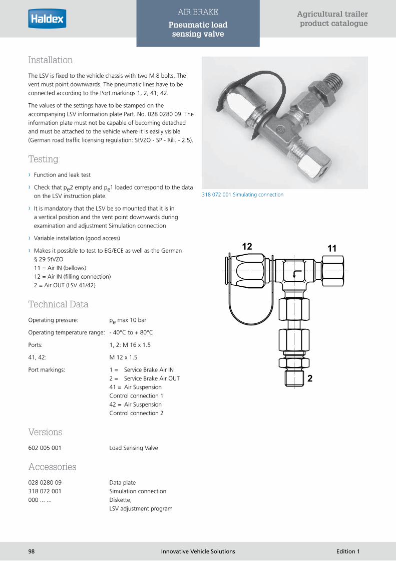
Installation
The LSV is fixed to the vehicle chassis with two M 8 bolts. The
vent must point downwards. The pneumatic lines have to be
connected according to the Port markings 1, 2, 41, 42.
The values of the settings have to be stamped on the
accompanying LSV information plate Part. No. 028 0280 09. The
information plate must not be capable of becoming detached
and must be attached to the vehicle where it is easily visible
(German road traffic licensing regulation: StVZO - SP - Rili. - 2.5).
Testing
› Function and leak test
› Check that pe2 empty and pe1 loaded correspond to the data
on the LSV instruction plate.
› It is mandatory that the LSV be so mounted that it is in
a vertical position and the vent point downwards during
examination and adjustment Simulation connection
› Variable installation (good access)
› Makes it possible to test to EG/ECE as well as the German
§ 29 StVZO
11 = Air IN (bellows)
12 = Air IN (filling connection)
2 = Air OUT (LSV 41/42)
Technical Data
Operating pressure: pe max 10 bar
Operating temperature range: - 40°C to + 80°C
Ports: 1, 2: M 16 x 1.5
41, 42: M 12 x 1.5
Port markings: 1 = Service Brake Air IN
2 = Service Brake Air OUT
41 = Air Suspension
Control connection 1
42 = Air Suspension
Control connection 2
Versions
602 005 001 Load Sensing Valve
Accessories
028 0280 09 Data plate
318 072 001 Simulation connection
000 ... ... Diskette,
LSV adjustment program
318 072 001 Simulating connection
98 Innovative Vehicle Solutions Edition 1
Agricultural trailer product catalogue
AIR BRAKE
Pneumatic load sensing valve

028 0280 09 LSV - data plate
99Edition 1 Innovative Vehicle Solutions
Agricultural trailer product catalogue
AIR BRAKE
Pneumatic load sensing valve
Air
bra
ke

System overview
The EB+ Gen3 system provides electro-pneumatic control of the
trailer brakes for full, semi and centre-axle trailers with built in
electronic load sensing and anti-lock functions. It provides the
necessary components to enable compatibility with either an
electronically and pneumatically signalled or a pneumatically only
signalled towing vehicle.
In addition to normal service brake control, EB+ Gen3 also
contains a roll stability system. This uses a lateral accelerometer,
in addition to the existing sensed variables, to determine if the
vehicle is close to its roll threshold. Low-level brake test pulses
are also used as part of the detection process and automatically
commanded braking is used to slow the vehicle below the roll
threshold. The accelerometer may be external or internal to the
ECU.
As well as providing the means for brake control the controller
also contains auxiliary channels capable of providing ancillary
functions, such as reset-to-ride height and a power / diagnostic
link for use by other systems. The main system package consists
of an electronic control unit (ECU) / modulator assembly,
containing a brake apply solenoid, twin solenoid operated relay
valve(s) and pressure sensors for monitoring the pneumatic
control line, brake delivery, reservoir and air suspension pressure.
Externally the system comprises two or four wheel speed sensors
and optionally a pressure sensor sensing the pneumatic control
transmission. When used the pressure sensor should be situated
before an emergency valve (REV or EV) if fitted.
Electronic braking system
Trailers fitted with the system may only be towed behind vehicles
fitted with an ISO 7638 connector (either 7 or 5-pin). When
connected with a 7-pin connector the system receives brake
demand data via the CAN data line in accordance with ISO
11992. When connected with a 5-pin connector the system
determines brake demand by sensing the pneumatic control
transmission.
Optionally an ISO 1185 (24N) or ISO 12098 (15 pole) stop light
power back-up connection can be fitted. This provides anti-lock
braking control and optionally dynamic load sensing in situations
where the ISO 7638 connection is not functioning and is not
intended as a normal operating mode. The apportionment of
braking under varying vehicle load conditions is implemented
in software. The load sensing parameters, from the brake
calculation, are programmed into the ECU using the system
diagnostic link.
Gen3 Standard: 823 008 XXX
100 Innovative Vehicle Solutions Edition 1
Agricultural trailer product catalogue
AIR BRAKE
Electronic braking system

Product versions
There are two versions of EB+ Gen3, a Standard version offering 4-2S / 2M with Super AUX, a Premium version offering up to
4S / 3M with Super AUX and additional auxiliary input / output capability.
EB+ Gen3 Standard [2M]
Independent EBS for semi and centre axle trailers. EB+ Gen3 2M, 2 modulators, 4 sensors, multiple auxiliary connections, integrated
stability, maximum flexibility. EB+ Gen3 Standard is a 12 / 24 V EBS with integrated roll-over control, intended for fitment to semi
and centre axle trailers using full air braking systems with air / mechanical suspension.
Benefits:
› Easy, logical vehicle installation
› Multi-voltage operation
› Integrated stability control
› Multiple auxiliary connections allow several devices to be fitted
› Functions and capabilities are upgradeable by software for longer operational life
› Connect multiple CAN devices, e.g. TPMS, Info Centre or telematics
Specifications:
› Integrated quick release valve
› Integrated anti-compound valve
› Service brake test ports
› ECU operates 8 - 32V
› EMC / RFI approved
› Reservoir M22 ports
› Valve integrated with electronic load sensing and roll-over control
› Delivery and suspension M16 ports
› External connections via up to 13 moulded plugs
› Plastic enclosure
› Dual reservoir connections
Feature Standard Premium
Wheel speed sensors 2 or 4 2 or 4
Modulators 2 2 or 3
Auxiliary inputs 2 analogue, 3 digital 2 analogue, 5 digital
Auxiliary outputs 3 outputs, 1 tacho 5 outputs, 1 tacho
Super AUX Yes Yes
Roll-over control Yes Yes
Auxiliary power extension No Yes
Haldex CAN-Bus Yes Yes
Power supply 8–32 V 8–32 V
Stop-lamp backup power Yes Yes
101Edition 1 Innovative Vehicle Solutions
Agricultural trailer product catalogue
AIR BRAKE
Electronic braking system
Air
bra
ke

Gen3 Master assembly 823 034 xxx
Gen3 Slave assembly 810 023 001
EB+ Gen3 Premium [2M or 3M]Independent EBS for full, semi and centre axle trailers. An EB+
Gen3 3M system is possible, consisting of a Gen3 2M Master
and a 1M Slave (3 modulators in total), 4 sensors, more auxiliary
connections than standard, integrated stability, maximum
flexibility. EB+ Gen3 Premium is a 12 / 24V EBS with integrated
roll-over control, intended for fitment to full, semi and centre
axle trailers using full air braking systems with air / mechanical
suspension. A top of the range configuration delivers EBS
braking with integrated ABS, electronic load-sensing, multiple
CAN, 3 modulator configuration, a range of other inputs /
outputs to control other functions and now with stop lamp
power backup.
Benefits:
› Easy, logical vehicle installation
› Multi-voltage operation
› Flexibility, with up to 5 input / output channels, 2 dedicated
analogue channels and 3 dedicated digital inputs
› Load sensing for both Master and Slave to optimise brake
efficiency and wear
› Connect multiple CAN devices, e.g. TPMS, Info Centre or
telematics.
Specifications:
› Integrated quick release valve
› Integrated anti-compound valve
› Service brake test ports
› ECU operates 8-32V
› EMC / RFI approved
› Reservoir M22 ports
› Valve integrated with electronic load sensing and roll-over
control
› Delivery and suspension M16 ports
› External connections via up to 14 moulded plugs
› Reservoir connections: 2 x Master, 1 x Slave
102 Innovative Vehicle Solutions Edition 1
Agricultural trailer product catalogue
AIR BRAKE
Electronic braking system

Option 2 Option 3Option 1
TEM® Park and shunt valveRelay Emergency Valve (REV)TrCM+
General components – 2M: Example only(customer preference)
(artists impression of layout)
Driver’s information plate
(customers preference)
Example only
(customers preference)
ISO 7638 7-pin
socket assembly
Sensor and exciter
(fitted as required)
EB+ Gen3 2M
assembly
EB+ Info Centre
ISO 12098 /
ISO 1185 (24N)
connector
EB+ IInInInfoffofofofofo CCCCCCCCCeneneneeenene trtrrrtt eeee
103Edition 1 Innovative Vehicle Solutions
Agricultural trailer product catalogue
AIR BRAKE
Electronic braking system
Air
bra
ke

2M- chassis components
2
1
6
7
3
4
8 7
6
2B
1
5
1B
2
4
6
7
6
7
2A1A
5
9
10
11
DIAGN
Item Description Notes
1 EB+ Gen3 assembly Standard version shown
2 EB+ label
3 ISO 7638 7-pin socket assembly
4 ISO 12098 / ISO 1185 (24N) Optional safety back up cable
5 EB+ Info Centre
6 Sensor assembly
7 Exciter
8 COLAS®+ Programmable via DIAG+
9 ILAS®-E Programmable via DIAG+
10 Lining Wear System (LWS) Programmable via DIAG+
11 EB+ external stability sensor Programmable via DIAG+
5
104 Innovative Vehicle Solutions Edition 1
Agricultural trailer product catalogue
AIR BRAKE
Electronic braking system

Option 2 Option 3Option 1
TEM®TrCM+
General components – 3M (Simplified overview)
Sensor and exciter
(fitted as required)
EB+ Gen3 3M
assembly
Driver’s information plate
(customers preference)
EB+ Info Centre
(customers preference)
ISO 7638 7-pin
socket assembly
ISO12098 / ISO1185 (24N)
connector
EB+ Infofofo CCCCCCenenenentrtt e
(customers preference)
Park and shunt valveRelay Emergency Valve (REV)
105Edition 1 Innovative Vehicle Solutions
Agricultural trailer product catalogue
AIR BRAKE
Electronic braking system
Air
bra
ke

3M-chassis components
3
1
6
7
7
6
2B1B
6
7
6
7
2A
1A
2
4
5
8
Item Description Notes
1 EB+ Gen3 assembly Premium version shown
2 Slave assembly
3 EB+ label
4 ISO 7638 7-pin socket assembly
5 ISO 12098 / ISO 1185 (24N) Optional safety back up cable
6 Sensor assembly
7 Exciter
8 3M link cable
106 Innovative Vehicle Solutions Edition 1
Agricultural trailer product catalogue
AIR BRAKE
Electronic braking system

Dimension and port identification
Standard-Assembly
Approximate mass of assembly: 5.75 Kg
Port 3
Delivery test
port 22
1
422
22 22 22 21 21
23 23 23 23
11
23 23
2121
1
41
155 mm
135 mm
74 mm
285 mm
30 mm
Studs x 3
M10 x 1.5 mm
182 mm
Port 3Delivery test
port 21
This way up
Port Description Notes
1 Reservoir port M22 x 1.5 mm
3 Exhaust port
4 Control port M16 x 1.5 mm
11 Anti - compounding port M16 x 1.5 mm
21/22 Delivery ports M16 x 1.5 mm
21/22 Test point port M12 x 1.5 mm
23 Spring brake port M16 x 1.5 mm
41 Air suspension port M16 x 1.5 mm
107Edition 1 Innovative Vehicle Solutions
Agricultural trailer product catalogue
AIR BRAKE
Electronic braking system
Air
bra
ke

Premium-assembly
Approximate mass of assembly: 5.75 Kg
Port 3
Delivery test port 22
285 mm
155 mm
135 mm
Port 3 Delivery test port
21
This way up
1
422
22 22 22 21 21
23 23 23 23
11
23 23
2121
1
41
74 mm
182 mm
30 mm
Studs x 3M10 x 1.5 mm
Port Description Notes
1 Reservoir port M22 x 1.5 mm
3 Exhaust port
4 Control port M16 x 1.5 mm
11 Anti - compounding port M16 x 1.5 mm
21/22 Delivery ports M16 x 1.5 mm
21/22 Test point port M12 x 1.5 mm
23 Spring brake port M16 x 1.5 mm
41 Air suspension port M16 x 1.5 mm
108 Innovative Vehicle Solutions Edition 1
Agricultural trailer product catalogue
AIR BRAKE
Electronic braking system

Slave assembly
Port Description Notes
1 Reservoir port M22 x 1.5 mm
2 Delivery ports M16 x 1.5 mm
3 Exhaust port -
4 Control port M16 x 1.5 mm
41 Air suspension port M16 x 1.5 mm
185 mm
185 mm
178 mm
Port 3
Port 3 Port 3 Port 3
162 mm
58 mm
This way up
4
2 2
2 1
41
2 2
2
Approximate mass of assembly: 3.2 Kg
Note:
The EB+ Gen3 Slave assembly (ECU & valve)
is only supplied as one complete unit that
cannot / should not be separated.
109Edition 1 Innovative Vehicle Solutions
Agricultural trailer product catalogue
AIR BRAKE
Electronic braking system
Air
bra
ke

System configurations
Semi & centre axle trailers - side by side (SxS)
1B
1A
1B
1A
1B
1A
1B
1A
1B
1A
S1B
S1A
1B
1A
S1B
S1A
2S/2M
2.12.2
2.12.2
2.12.2
2.12.2
2.12.2
2.12.2
2.12.2
2.12.2
2.1
2.2
Notes:
› Any axle without directly controlled wheels may be a lift axle
› Any axle may be a steered axle
2S / 2M
ISO
Connector
end
EPRV’S
110 Innovative Vehicle Solutions Edition 1
Agricultural trailer product catalogue
AIR BRAKE
Electronic braking system

2.1
2.2
ISO
Connector
end
EPRV’S
Semi & centre axle trailers - side by side (SxS)
1B
1A
1B
1A
1B
1A
4S/2M
2.12.2
2.12.2
2.12.2
2B
2A
1B
1A
2.12.2
2B
2A
2B
2A
1B
1A
2.12.2
2B
2A
1B
1A
2.12.2
2B
2A
2B
2A
1B
1A
2.12.2
2B
2A
1B
1A
2.12.2
2B
2A
4S / 2M
Preferred option
Preferred option
Notes:
› Any axle without directly controlled wheels may be a lift axle
› Any axle may be a steered axle
111Edition 1 Innovative Vehicle Solutions
Agricultural trailer product catalogue
AIR BRAKE
Electronic braking system
Air
bra
ke

Semi & centre axle trailers
Notes:
› Sensed axles cannot be lifted
› Any axle without directly controlled wheels may be a lifted
› N1 Master ECU is mounted to EPRV’s 21/22. All sensors must be connected to this
Master ECU
› N2 Slave ECU is mounted to EPRV 2 and is controlled by Master ECU.Slave ECU /
EPRV 2 is shown facing rear but can also be installed facing forward, left or right, as
EPRV 2 is always select low control
S1B
S1A
S2B
S2A
4S/3M
S1A
S1B
S2A
S2B
2 2.12.2
2 2.12.2
S1B
S1A
S2B
S2A
2 2.12.2
4S / 3M
2eU E
2.1
2.2E
nectorISO
Connector
end
Slave
ECU
EPRV’S
EPRV
S1B
S1A
S2B
S2A
4S/3M
S1A
S1B
S2A
S2B
2 2.12.2
22.22.1
S1B
S1A
S2B
S2A
22.22.1
4S / 3M
112 Innovative Vehicle Solutions Edition 1
Agricultural trailer product catalogue
AIR BRAKE
Electronic braking system
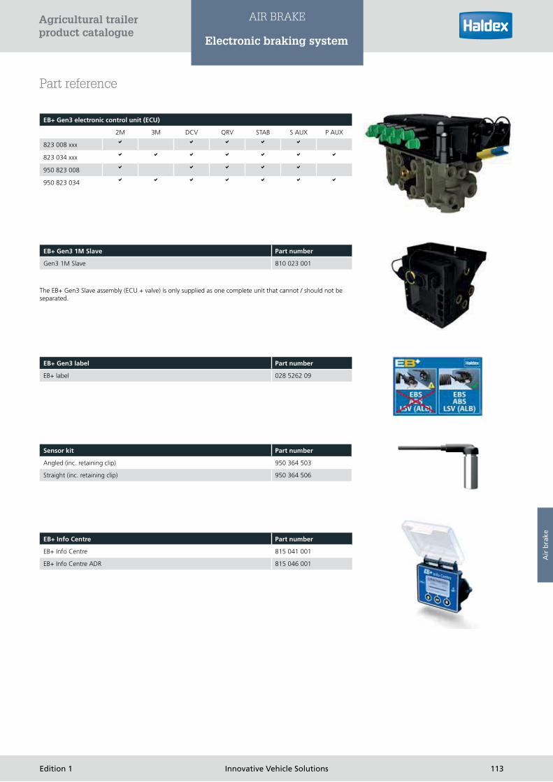
EB+ Gen3 electronic control unit (ECU)
2M 3M DCV QRV STAB S AUX P AUX
823 008 xxx
823 034 xxx
950 823 008
950 823 034
Part reference
The EB+ Gen3 Slave assembly (ECU + valve) is only supplied as one complete unit that cannot / should not be
separated.
EB+ Gen3 1M Slave Part number
Gen3 1M Slave 810 023 001
EB+ Gen3 label Part number
EB+ label 028 5262 09
Sensor kit Part number
Angled (inc. retaining clip) 950 364 503
Straight (inc. retaining clip) 950 364 506
EB+ Info Centre Part number
EB+ Info Centre 815 041 001
EB+ Info Centre ADR 815 046 001
113Edition 1 Innovative Vehicle Solutions
Agricultural trailer product catalogue
AIR BRAKE
Electronic braking system
Air
bra
ke

111144 Innovavatitivev VVehehiciclele SSololo utions Editioonn 1
Agricultural trailerproduct catalogue

ACTUATION
Brake chamber 116
Double diaphragm spring brake - Blue Seal 128
Piston cylinder 132
Automatic brake adjuster 135
115EdEdititioion n 11 InInnon vativeve Vehehiciclele SSololututioionsn
AgAgAg iricultural trailerproduct catalogue
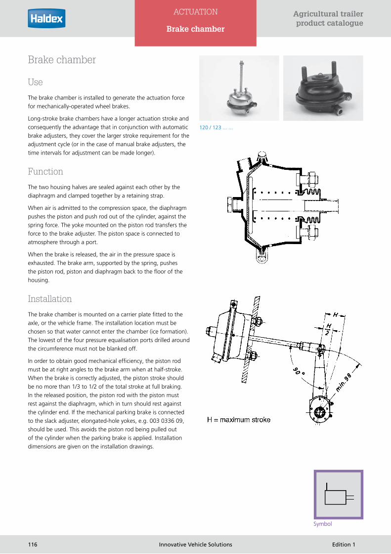
Brake chamber
Use
The brake chamber is installed to generate the actuation force
for mechanically-operated wheel brakes.
Long-stroke brake chambers have a longer actuation stroke and
consequently the advantage that in conjunction with automatic
brake adjusters, they cover the larger stroke requirement for the
adjustment cycle (or in the case of manual brake adjusters, the
time intervals for adjustment can be made longer).
Function
The two housing halves are sealed against each other by the
diaphragm and clamped together by a retaining strap.
When air is admitted to the compression space, the diaphragm
pushes the piston and push rod out of the cylinder, against the
spring force. The yoke mounted on the piston rod transfers the
force to the brake adjuster. The piston space is connected to
atmosphere through a port.
When the brake is released, the air in the pressure space is
exhausted. The brake arm, supported by the spring, pushes
the piston rod, piston and diaphragm back to the floor of the
housing.
Installation
The brake chamber is mounted on a carrier plate fitted to the
axle, or the vehicle frame. The installation location must be
chosen so that water cannot enter the chamber (ice formation).
The lowest of the four pressure equalisation ports drilled around
the circumference must not be blanked off.
In order to obtain good mechanical efficiency, the piston rod
must be at right angles to the brake arm when at half-stroke.
When the brake is correctly adjusted, the piston stroke should
be no more than 1/3 to 1/2 of the total stroke at full braking.
In the released position, the piston rod with the piston must
rest against the diaphragm, which in turn should rest against
the cylinder end. If the mechanical parking brake is connected
to the slack adjuster, elongated-hole yokes, e.g. 003 0336 09,
should be used. This avoids the piston rod being pulled out
of the cylinder when the parking brake is applied. Installation
dimensions are given on the installation drawings.
Symbol
120 / 123 ... ...
116 Innovative Vehicle Solutions Edition 1
Agricultural trailer product catalogue
ACTUATION
Brake chamber

Testing
› Check the bellows (if fitted) for damage and replace as necessary
› Check the brake chamber response pressure: max. pe = 0.5 bar max
› Check the stroke is correctly set: The piston stroke at full braking should be some 1/3 to 1/2 of the total stroke.
If the stroke at full braking is longer than 1/2 of the possible stroke, the brake must be adjusted (this does not apply to automatic
slack adjusters; however, these must be checked for operation and their basic setting)
› After releasing check the brake to see whether the piston rod has returned completely
Technical data
Service temperature: -40°C to +80°C
Service pressure: pe max. 10 bar
Certificate for brake chamber
type 9 to type 36: BC 0094.0 to BC 0100.0
Swivel range for plunger rod is 3° all round.
The diaphragm is guaranteed to return to its initial position within the stated temperature range.
Find further information on www.haldex.com/trailer-application-guide
Part number Type Stroke Piston rod thread
Piston rod thread Seal Central fork
headSide port Port Vent plug Operating
pressure Lock nut
123 090 001 9 60 185mm M 16x 1,5 Air bellows without M 16 x 1,5 with 8 bar with
123 120 002 12 60 185mm M 16x 1,5 Air bellows without M 16 X 1,5 M 16 X 1,5 with 8 bar with
123 160 001 16 80 185mm M 16x 1,5 Disc without M 16 x 1,5 M 16 x 1,5 with 8 bar with
123 160 002 16 80 185mm M 16x 1,5 Air bellows without M 16 x 1,5 M 16 x 1,5 with 8 bar with
123 200 001 20 76 185mm M 16 x 1,5 Disc without M 16 X 1,5 M 16 X 1,5 with 8 bar with
123 200 002 20 76 185mm M 16 x 1,5 Air bellows without M 16 X 1,5 M 16 X 1,5 with 8 bar with
123 200 003 20 76 210 M 16 x 1,5 Disc without M 16 x 1,5 M 16 X 1,5 with 8 bar with
123 240 001 24 80 185 M 16 x 1,5 Disc without M 16 X 1,5 M 16 X 1,5 1 with 8 bar with
123 240 002 24 80 185 M 16 x 1,5 Air bellows without M 16 X 1,5 M 16 X 1,5 with 8 bar with
123 240 003 24 80 210 M 16 x 1,5 Disc without M 16 X 1,5 M 16 X 1,5 with 8 bar with
123 240 004 24 80 148 M 16 x 1,5 Disc without M 16 X 1,5 M 16 X 1,5 with 8 bar with
123 300 001 30 80 185 M 16 x 1,5 Disc without M 16 X 1,5 M 16 X 1,5 with 8 bar with
123 300 002 30 80 185 M 16 x 1,5 Air bellows without M 16 X 1,5 M 16 X 1,5 with 8 bar with
123 300 003 30 80 210 M 16 x 1,5 Disc without M 16 X 1,5 M 16 X 1,5 with 8 bar with
120 366 201 30 75 187 M 16 x 1,5 Disc without M 16 X 1,5 with 8 bar with
123 360 004 36 75 60 M 16 x 1,5 Air bellows without M 16 X 1,5 with 8 bar with
120 376 102 36 75 192 M 16 x 1,5 Air bellows without M 16 X 1,5 with 8 bar with
Versions
117Edition 1 Innovative Vehicle Solutions
Agricultural trailer product catalogue
ACTUATION
Brake chamber
Act
uat
ion

003 0336 09 003 5614 09
003 5685 09
Available yokes
118 Innovative Vehicle Solutions Edition 1
Agricultural trailer product catalogue
ACTUATION
Brake chamber

ED
R/C
W 7
/9/0
8
119Edition 1 Innovative Vehicle Solutions
Agricultural trailer product catalogue
ACTUATION
123 090 001
Act
uat
ion

120 Innovative Vehicle Solutions Edition 1
Agricultural trailer product catalogue
ACTUATION
123 120 002

ED
R/C
W 7
/9/0
8
121Edition 1 Innovative Vehicle Solutions
Agricultural trailer product catalogue
ACTUATION
123 160 001
Act
uat
ion

122 Innovative Vehicle Solutions Edition 1
Agricultural trailer product catalogue
ACTUATION
123 200 001

123Edition 1 Innovative Vehicle Solutions
Agricultural trailer product catalogue
ACTUATION
123 240 001
Act
uat
ion

124 Innovative Vehicle Solutions Edition 1
Agricultural trailer product catalogue
ACTUATION
123 300 001

125Edition 1 Innovative Vehicle Solutions
Agricultural trailer product catalogue
ACTUATION
123 360 004
Act
uat
ion
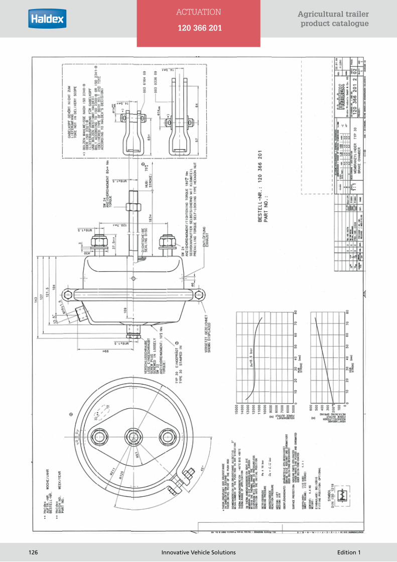
126 Innovative Vehicle Solutions Edition 1
Agricultural trailer product catalogue
ACTUATION
120 366 201

127Edition 1 Innovative Vehicle Solutions
Agricultural trailer product catalogue
ACTUATION
120 376 102
Act
uat
ion

Double diaphragm spring brake - Blue Seal
Use
Double diaphragm brake chambers consist of one diaphragm
unit for the service brake, and one diaphragm spring unit for
the parking brake. These chambers are used for mechanically-
operated S-cam/disc brakes.
Function
Diaphragm unit for the service brake
The two housing halves are sealed against each other by the
diaphragm and clamped together by a retaining strap. When air
is admitted to the compression space via port 11 (service), the
diaphragm pushes the piston and push rod out of the cylinder,
against the spring force. The yoke mounted on the piston rod
transfers the force to the wheel brake, via the slack adjuster.
The piston space is connected to atmosphere through a port.
When the service brake is released, the air in the pressure space
is exhausted. The brake arm, supported by the spring, pushes
the piston rod, piston and diaphragm back to the floor of the
housing. The two diaphragm units operate independently of
each other.
Diaphragm spring unit for the parking brake
When the air is exhausted from the compression space via port
12, the spring pushes the piston rod of the spring actuator unit,
via the diaphragm, against the piston rod of the service brake
unit. The yoke mounted on the piston rod transfers the force
to the wheel brake, via the slack adjuster. When the brake is
released, air is admitted to the connection again.
Mechanical release device
The double-diaphragm combined brake cylinder has a
mechanical release device. If there is a compressed air loss, the
spring can be preloaded mechanically using the release tool
mounted on the cylinder in order to release the wheel brake.
Symbol
135 /136 ... ...
Version Type Stroke (mm) X-minimum
drum brake 20/30 76 86
drum brake 24/30 76 86
drum brake 30/30 76 86
Versions
128 Innovative Vehicle Solutions Edition 1
Agricultural trailer product catalogue
ACTUATION
Double diaphragm spring brake

Installation
Please observe the following instructions for safe and permanent
mounting:
The mounting bracket for the spring brake actuator must be flat
and adequately dimensioned as regards material thickness and
size. The actuator must not overhang.
The mounting surface of the bracket must not have been given
the final paint coat before the actuator is mounted.
No intermediate plates, plain washers, spring washers etc.
should be fitted between the bracket mounting surface and the
service brake unit. Make sure the actuator is mounted directly.
The maximum excursion of the piston rod in all directions is 3‘.
The lowest of the drilled pressure equalisation ports must not be
blanked off
The piston rod length has been correctly selected if the piston
rests against the diaphragm in the rest position and when in the
working position, forms a right angle with slack adjuster at half
stroke.
Observe the tightening torques for the mounting nuts.
Tighten the nuts alternately and in stages.
Before taking the vehicle into operation, the release tool must be
removed and stowed in place provided. Close off the port with
the dust protection cap.
Directions and approvals by the axle and vehicle manufacturer
must be observed.
Please note: Spring brake actuator housing parts must not be
dismantled (danger of injury).
Testing
Test the cylinder/connections for operation and leaks.
Technical data
Medium: air
Service pressure: max. 10.2 bar.
Thermal application range: -40°C to +80°C
Ports: M16 x 1.5
Mounting studs: M 16 x 1.5
Certificate for double diaphragm spring brake
Typ 20/30: BC 0166.0
Typ 24/30: BC 0167.0
Typ 30/30: BC 0168.0
Find further information on
www.haldex.com/trailer-application-guide
Part number Type Stroke Weight Seal C lock nut D plain washer
E released with tool
G thread protective cap
J K S* Tension band
T*Port
136 2030 001 20/30 76/76 8,7 kg Sealing
washer
with Yes Yes Yes 208 mm 246 mm 315° 90°
136 2430 001 24/30 76/76 8,7 kg Sealing
washer
with Yes Yes Yes 208 mm 246 mm 315° 90°
136 2430 002 24/30 76/76 8,7 kg Sealing
washer
without without Yes Yes 188 mm 227 mm 45° 90°
136 3030 001 30/30 76/76 9,7 kg Sealing
washer
with Yes Yes Yes 208 mm 246 mm 315° 90°
Versions
129Edition 1 Innovative Vehicle Solutions
Agricultural trailer product catalogue
ACTUATION
Double diaphragm spring brake
Act
uat
ion

136 2030
130 Innovative Vehicle Solutions Edition 1
Agricultural trailer product catalogue
ACTUATION
Double diaphragm spring brake

136 2430
136 3030
131Edition 1 Innovative Vehicle Solutions
Agricultural trailer product catalogue
ACTUATION
Double diaphragm spring brake
Act
uat
ion

Piston cylinder
Use
The piston cylinder can be fitted in all air brake systems to
actuate mechanically-operated wheel brakes.
It can also be used as a control cylinder to actuate other kinds of
equipment.
Function
When compressed air is admitted to the piston cylinder, it pushes
the piston and push rod out of the cylinder. The push rod,
which runs in a loose guide ring in the guide tube, transfers the
generated braking force to the brake arm through its yoke. In its
released position, the spring pushes the guide tube into its end
position. The bellows protects the cylinder interior against dust
and splash water. Small flaps in the bellows connect the spaces
before the piston with atmosphere.
Installation
The cylinder is mounted on a carrier plate fitted to the axle, or
the vehicle frame, with four mounting bolts. Make sure when
doing this that the cylinder is tilted towards the yoke in order
to prevent the ingress of water. When the brake is correctly
adjusted, the piston stroke should be no more than 1/3 to 1/2 of
340 029
340 005
Symbol
132 Innovative Vehicle Solutions Edition 1
Agricultural trailer product catalogue
ACTUATION
Piston cylinder
Part number Diameter (mm)
Stroke (mm)
Average force at 6 bar L* C* X* Y* Z* Bracket tension band Note
340 005 001 100 135 4200N 300 140 14 14 28 with with
340 008 001 125 135 6700N 335 170 14 14 28 with with
340 011 001 140 155 8400N 355 170 14 14 - with with A140 DIN74282
340 011 021 140 155 8400N 355 170 14 14 - with with Special version
340 013 001 150 155 9700N 355 157 14 14 - with with
340 029 001 65 105 1800N 253 128 12 12 24 with -
340 029 011 65 105 1800N 265 137 14 14 28 with -
340 029 031 65 105 1800N 253 128 12 12 24 with - without piston return spring
340 029 041 65 105 1800N 253 128 12 12 24 with - Special version
Versions

340 008
the total stroke. The brake arm and piston rod should form a right angle so as to maximise the efficiency of the force transmission.
When determining the length of the brake arm, pay attention to the maximum permissible deflection of the swivelling piston rod. In
the released position, the piston rod must rest against the end of the piston.
Testing
› Test the bellows.
› Check the cylinder response pressure: max. 0.5 bar.
› Check the piston cylinder stroke is correctly set:
Full braking should be approx. 1/3 to 1/2 of the total stroke, anything over this needs adjusting. Release the brake and check that
the cylinder piston returns completely.
Technical data
Service pressure: max. 8 bar.
340 005
133Edition 1 Innovative Vehicle Solutions
Agricultural trailer product catalogue
ACTUATION
Piston cylinder
Act
uat
ion

340 011
340 013
340 029
134 Innovative Vehicle Solutions Edition 1
Agricultural trailer product catalogue
ACTUATION
Piston cylinder

135Edition 1 Innovative Vehicle Solutions
Agricultural trailer product catalogue
ACTUATION
Automatic brake adjusters
Automatic brake adjusters
Use
Haldex automatic brake adjusters have revolutionised installation and adjustment procedures for trailer axles. The innovative
construction of the self-adjusting version S-ABA makes installation much simpler. Conventional automatic brake adjusters have the
control arm in a fixed position. S-ABA functions independently of the angle of the control arm. At the same time, this flexibility
means that installation is faster, because the it is no longer necessary to spend time adjusting the control arm for the correct amount
of play. And because you’re free to select the angle of the control arm, faulty installation or initial setting is no longer a problem –
it’s practically impossible to install or adjust the S-ABA incorrectly.
S-ABA
› Self-setting adjustment for faster and easier installation
› Always functions correctly – independently of the position of the control arm
› Replaces fixed control arm adjusters, thus reducing number of components needed in stock
› Enables supply of axles with pre-installed automatic brake adjusters
› Readjustment is graduated in order to reduce the risk of excessive readjustment when performing an emergency stop
› Can be supplied with Haldex’s electronic brake-wear sensor as an option
Act
uat
ion

Part number Casting Control unitNumber of teeth
L1 L2 L3 L4 L5 L6 L7Bearing (mm)
OffsetTilt (de-grees)
Gearing type
80019D 5027 530 10 250 180 165 150 135 120 - 14 0 +20 SAE 1 1/2” 10 C
800195S 5027 530 10 250 180 165 150 135 120 - 14 0 +20 SAE 1 1/2” 10 C
80020D 5027 530 10 205 153 140 127 115 - - 14 SAE 1 1/2” 10 C
80020S 5027 530 10 205 153 140 127 115 - - 14 SAE 1 1/2” 10 C
80021D 5027 530 37 215 153 129 105 - - - 14 (L1:L16) 0 +20 SAE J 498
800215 5027 530 37 215 153 129 105 - - - 14 (L1:L16) 0 +20 SAE J 498
80022D 5027 530 10 250 180 155 140 125 105 - 14 0 +20 SAE 1 1/2” 10 C
800DDS 5027 530 10 250 180 155 140 125 105 - 14 0 +20 SAE 1 1/2” 10 C
80023D 5027 530 10 215 153 129 105 - - - 14 (L1:L16) 0 +20 SAE 1 1/2” 10 C
80023S 5027 530 10 215 153 129 105 - - - 14 (L1:L16) 0 +20 SAE 1 1/2” 10 C
80024D 5027 530 10 210 180 150 125 - - - 14 0 +20 SAE 1 1/2” 10 C
80024S 5027 530 10 210 180 150 125 - - - 14 0 +20 SAE 1 1/2” 10 C
80484C 5027 74530 10 180 150 125 105 - - - 14 0 +20 SAE 1 1/2” -10 C
80495D 5027 530 10 250 180 165 150 135 120 - 14 0 +20 SAE 1 1/2” -10 C
80495S 5027 530 10 250 180 165 150 135 120 - 14 0 +20 SAE 1 1/2” -10 C
80584D 5027 530 10 180 165 150 135 120 - - 14 0 +20 SAE 1 1/2” -10 C
80584S 5027 530 10 180 165 150 135 120 - - 14 0 +20 SAE 1 1/2” -10 C
136 Innovative Vehicle Solutions Edition 1
Agricultural trailer product catalogue
ACTUATION
Automatic brake adjusters

..........................................................................................................................
..........................................................................................................................
..........................................................................................................................
..........................................................................................................................
..........................................................................................................................
..........................................................................................................................
..........................................................................................................................
..........................................................................................................................
..........................................................................................................................
..........................................................................................................................
..........................................................................................................................
..........................................................................................................................
..........................................................................................................................
..........................................................................................................................
..........................................................................................................................
..........................................................................................................................
..........................................................................................................................
..........................................................................................................................
..........................................................................................................................
..........................................................................................................................
..........................................................................................................................
..........................................................................................................................
..........................................................................................................................
..........................................................................................................................
..........................................................................................................................
..........................................................................................................................
..........................................................................................................................
..........................................................................................................................
..........................................................................................................................
..........................................................................................................................
..........................................................................................................................
..........................................................................................................................
..........................................................................................................................
..........................................................................................................................
137Edition 1 Innovative Vehicle Solutions
Agricultural trailer product catalogue NOTES

138 InInnonovative Vehicle Solutions Eddititiionn 11
AgAgriricucuulttuururala traraillerreprproddo ucuuctt cacatatat lologuguee

AIR SUSPENSION
1139Edition 1 Innovaatit ve Vehhiclele SSololutions
AgAgriricucultltururalal ttrar ilerprprododucct t cacatalolologugueee
Levelling valve 140

Levelling valve
Use
The levelling valve is installed as a level control valve for load
dependent control using the air bellows of vehicles with air sus-
pension. Depending on the version, additional functions, such as
second ride height, through a lap position control, are possible.
Function
Levelling valves are fixed to the vehicle chassis and connected
to the axle via a control lever and linkage. With the vehicle or
trailer stationary the valve is in a state of rest in the so called
lap position, i.e. both inlet as well as outlet is closed. By loading
the vehicle the chassis (frame) moves down toward the axle,
this way the linkage and the control lever are lifted and the inlet
port is opened. Supply air at port 1 now flows via the check
valve, over the opened inlet, through the area between piston
and inlet ports via connection 21 and 22 to the air bellows. The
chassis (frame) is now raised until the control lever is horizontal
again, and therefore in the lap position.
By unloading the vehicle the chassis is raised because of the
high bellows pressure. By means of the linkage the control
lever moves down. The movement of the control lever transfers
air from ports 21 and 22 to the piston, which opens on the
downward trend and opens the outlet. Through the open
outlet air now flows from the air bellows out to atmosphere,
whereby the chassis (frame) again is lowered to the ride position,
(levelling valve control lever horizontal). On vehicles with only
one levelling valve per axle (bogie), the air bellows of the left and
right side will be supplied with air from this one levelling valve.
To avoid instability on cornering, valves are fitted with a cross
restriction. Through a particular design the inlet valve part will
provide a delayed pressurization between connection 21 and 22
on the left and right side of the vehicle (when exchanging valves
use only the same Part No).
On versions with a lap position control a second ride height is
available. With it a so-called kneeling (one sided lowering of the
chassis) is possible e.g. on buses or vehicles with lift axles. This
levelling valve is controlled over an external control port and
shifts the lap position. Therefore it is possible to raise or lower
the chassis around a certain value. On lifted axles the wheels
do not touch the ground when passing over uneven ground i.e.
speed bumps, therefore reduced tyre wear. A further use is the
adjustment at different saddle heights.
612 032 ...
140 Innovative Vehicle Solutions Edition 1
Agricultural trailer product catalogue
AIR SUSPENSION
Levelling valve
Symbols

Additional functions
In addition to the basic versions of the levelling valve are those
with so-called additional functions. These include:
› Valves with cross-throttling
› Valves with height limitation (see 612 032 ...)
› Valves with cross-throttling and height limit
(see 612 032 ...)
› Valves with zero adjustment for second ride height
(see 612 046 ...)
Flow diagram
Assembly of plastic tube Dismantling plastic tube
1. press in clamp ring
2. remove plastic tube
141Edition 1 Innovative Vehicle Solutions
Agricultural trailer product catalogue
AIR SUSPENSION
Levelling valve
Air
su
spen
sio
n

Mechanical part
The levelling valve has to be installed vertically with exhaust port
at bottom. For fixing use at least two M8 screws. Where only
one valve per bogie is used the valve must be located in the area
of the middle of the axle.
The freedom of movement of the centre axle is to be checked.
The linkages are to be installed distortion free.
Pneumatic part
On valves with push-in fittings use only nylon pipes 8x1 in
accordance with DIN 74 324 or 1/4“ x 0,04 in accordance with
SAE J844. When assembling the nylon pipes, care should be
taken to ensure that the pipes are cut square, to the required
length and are free from burrs. Before inserting the pipes in
the push-in fittings support sleeves, e.g. in accordance with
HALDEX order number 032 0490 09 should be installed in the
ends of the pipes. Pipes are to be inserted at least 22 mm deep
in the connections.*
In the event of paint/coating work all open connections
including the exhaust port should be protected by suitable
means to avoid penetration of the paint/coating. After painting/
coating remove this protecting material.
In the supply coming from the air reservoir a line filter should be
installed (to guard against pollutants).
Arrow marking must indicate
direction of linkage
More versions on request
Part number Version Ports Nominal diameter/type Linkage 003 5757 09 Symbol
612 035 001 A M 12 x 1,5 1,25 without I
612 035 011 A M 12 x 1,5 1,25 supplied separately I
612 035 021 A M 12 x 1,5 3 supplied separately I
612 035 031 A M 12 x 1,5 4 supplied separately II
612 035 041 B Push-in 8x1 1,25 supplied separately I
612 035 051 B Push-in 8x1 3 supplied separately I
612 035 061 B Push-in 8x1 4 supplied separately II
612 035 071 B Push-in 8x1 5 supplied separately II
Versions
142 Innovative Vehicle Solutions Edition 1
Agricultural trailer product catalogue
AIR SUSPENSION
Levelling valve

Version B
Version A
Twisting the control levers around 180°
equal function to the drawn position is
reached, within a tolerance.
Linkage on the axle: 612 025 001
Linkage on valve: 003 5757 09
143Edition 1 Innovative Vehicle Solutions
Agricultural trailer product catalogue
AIR SUSPENSION
Levelling valve
Air
su
spen
sio
n

Settings
After installation of the valve and connecting the pipe fittings
the length of the connecting rod must be determined between
axle and valve, after the vehicle chassis has been set at the
desired height (vehicle manufacturer- specification). The raising
of the frame or chassis to this desired height is reached by lifting
the control lever to position “charging”. By this process the air
bel- lows are inflated with air.
On reaching the desired height the control lever must be
positioned immediately in the lap position, which can be the
horizontal position (dependent on version), and fix it with a
locking pin (d=4H8) on housing and on bore of the spindle. The
actual length of the connecting rod between the linkage to axle
and the linkage at the control lever can now be determined, and
the connecting rod can be fastened. The connecting rod is to be
connected using the rubber linkages and fastened with the hose
clamps supplied
LAST OF ALL: (REMOVE LOCKING PIN)
After removal of the retaining ring it is possible to remove the
plastic pipe by pushing the clamp ring in. (e.g. to replace valve).
Ex-factory the lap position is set horizontal to the control lever
(excluding versions 612 036 001 / 051 001 / 011. If not in the
lap position it can be adjusted to the horizontal position by the
following method:
To lock the lap position, use pin d=4H8 x 20 DIN 7 to fix spindle
as well as linkage (d= 6 mm) in horizontal position. Remove the
rubber boot and filter pad. With a screwdriver turn the valve
tappet so far, that neither a rise nor drop in pressure occurs.
As an alternative an adjustment at the linkage to axle 612 025
001 is possible: loosen counter nut and shift angles at the axle
bracket accordingly. Tighten locknut again.
Testing
If defects are noted during vehicle examinations or when
driving, then the unit should be exchanged. When working with
high pressure cleaners a distance of at least 50 cm should be
observed. Missing exhaust caps are to be renewed.
Check function and leak - tightness of the unit. In the lap
position at the delivery ports 21, 22 neither rise of pressure nor
drop of pressure should result. Free movement and condition of
the linkage is to be checked, bent or welded linkages are to be
exchanged. Brittle or hardened rubber pieces are to be renewed.
Technical data
Operating pressure, dyn.: pe max. 13 bar
permitted dyn.bellow pressure: pe max. 20 bar
Operating temperature: - 45°C to + 85°C
Operating range
(charging - and exhausting): 45°
Side of control: on the left and on the right
Dead angle at 7 - 8 bars: 2°
Port description: 1 = inlet port
2 = delivery port
3 = exhaust
144 Innovative Vehicle Solutions Edition 1
Agricultural trailer product catalogue
AIR SUSPENSION
Levelling valve

..........................................................................................................................
..........................................................................................................................
..........................................................................................................................
..........................................................................................................................
..........................................................................................................................
..........................................................................................................................
..........................................................................................................................
..........................................................................................................................
..........................................................................................................................
..........................................................................................................................
..........................................................................................................................
..........................................................................................................................
..........................................................................................................................
..........................................................................................................................
..........................................................................................................................
..........................................................................................................................
..........................................................................................................................
..........................................................................................................................
..........................................................................................................................
..........................................................................................................................
..........................................................................................................................
..........................................................................................................................
..........................................................................................................................
..........................................................................................................................
..........................................................................................................................
..........................................................................................................................
..........................................................................................................................
..........................................................................................................................
..........................................................................................................................
..........................................................................................................................
..........................................................................................................................
..........................................................................................................................
..........................................................................................................................
..........................................................................................................................
145Edition 1 Innovative Vehicle Solutions
Agricultural trailer product catalogue NOTES

..........................................................................................................................
..........................................................................................................................
..........................................................................................................................
..........................................................................................................................
..........................................................................................................................
..........................................................................................................................
..........................................................................................................................
..........................................................................................................................
..........................................................................................................................
..........................................................................................................................
..........................................................................................................................
..........................................................................................................................
..........................................................................................................................
..........................................................................................................................
..........................................................................................................................
..........................................................................................................................
..........................................................................................................................
..........................................................................................................................
..........................................................................................................................
..........................................................................................................................
..........................................................................................................................
..........................................................................................................................
..........................................................................................................................
..........................................................................................................................
..........................................................................................................................
..........................................................................................................................
..........................................................................................................................
..........................................................................................................................
..........................................................................................................................
..........................................................................................................................
..........................................................................................................................
..........................................................................................................................
..........................................................................................................................
..........................................................................................................................
146 Innovative Vehicle Solutions Edition 1
Agricultural trailer product catalogueNOTES

..........................................................................................................................
..........................................................................................................................
..........................................................................................................................
..........................................................................................................................
..........................................................................................................................
..........................................................................................................................
..........................................................................................................................
..........................................................................................................................
..........................................................................................................................
..........................................................................................................................
..........................................................................................................................
..........................................................................................................................
..........................................................................................................................
..........................................................................................................................
..........................................................................................................................
..........................................................................................................................
..........................................................................................................................
..........................................................................................................................
..........................................................................................................................
..........................................................................................................................
..........................................................................................................................
..........................................................................................................................
..........................................................................................................................
..........................................................................................................................
..........................................................................................................................
..........................................................................................................................
..........................................................................................................................
..........................................................................................................................
..........................................................................................................................
..........................................................................................................................
..........................................................................................................................
..........................................................................................................................
..........................................................................................................................
..........................................................................................................................
147Edition 1 Innovative Vehicle Solutions
Agricultural trailer product catalogue NOTES

Innovative Vehicle Solutions www.haldex.com
Haldex develops and provides reliable and
innovative solutions with focus on brake
and air suspension products to the global
commercial vehicle industry.
Listed on the Stockholm Stock Exchange,
Haldex has annual sales of approximately 4.4
billion SEK and employs about 2,235 people.
AustriaHaldex Wien Ges.m.b.H.
Vienna
Tel.: +43 1 8 69 27 97
Fax: +43 1 8 69 27 97 27
E-Mail: [email protected]
BelgiumHaldex N.V.
Balegem
Tel.: +32 9 363 90 00
Fax: +32 9 363 90 09
E-Mail: [email protected]
BrazilHaldex do Brasil Ind. E Com.
Ltda
São José dos Campos
Tel.: +55 12 3935 4000
Fax: +55 12 3935 4018
E-Mail: [email protected]
CanadaHaldex Ltd
Cambridge, Ontario
Tel.: +1 519 621 6722
Fax: +1 519 621 3924
E-Mail: [email protected]
ChinaHaldex Vehicle Products Co. Ltd.
Suzhou
Tel.: +86 512 8885 5301
Fax: +86 512 8765 6066
E-Mail: [email protected]
FranceHaldex Europe SAS
Weyersheim
Tel.: +33 3 88 68 22 00
Fax: +33 3 88 68 22 09
E-Mail: [email protected]
GermanyHaldex Brake Products GmbH
Heidelberg
Tel.: +49 6 221 7030
Fax: +49 6 221 703400
E-Mail: [email protected]
HungaryHaldex Hungary Kft
Szentlörinckáta
Tel.: +36 29 631 400
Fax: +36 29 631 401
E-Mail: [email protected]
IndiaHaldex India Limited
Nashik
Tel.: +91 253 66 99 501
Fax: +91 253 23 80 729
ItalyHaldex Italia Srl.
Biassono
Tel.: +39 039 47 17 02
Fax: +39 039 27 54 309
E-Mail: [email protected]
©2015, Haldex AB. This material may contain
Haldex trademarks and third party trademarks,
trade names, corporate logos, graphics and
emblems which are the property of their respective
companies. The contents of this document may not
be copied, distributed, adapted or displayed for
commercial purposes or otherwise without prior
written consent from Haldex.
KoreaHaldex Korea Ltd.
Seoul
Tel.: +82 2 2636 7545
Fax: +82 2 2636 7548
E-Mail: [email protected]
MexicoHaldex de Mexico S.A. De C.V.
Monterrey
Tel.: +52 81 8156 9500
Fax: +52 81 8313 7090
PolandHaldex Sp. z.o.o.
Praszka
Tel.: +48 34 350 11 00
Fax: +48 34 350 11 11
E-Mail: [email protected]
RussiaOOO “Haldex RUS”
Moscow
Tel.: +7 495 747 59 56
Fax: +7 495 786 39 70
E-Mail: [email protected]
SpainHaldex España S.A.
Granollers
Tel.: + 34 93 84 07 239
Fax: + 34 93 84 91 218
E-Mail: [email protected]
SwedenHaldex Brake Products AB
Landskrona
Tel.: +46 418 47 60 00
Fax: +46 418 47 60 01
E-Mail: [email protected]
United KingdomHaldex Ltd.
Newton Aycliffe
Tel.: +44 1325 310 110
Fax: +44 1325 311 834
E-Mail: [email protected]
Haldex Brake Products Ltd.
MIRA Technology Park
Tel.: +44 2476 400 300
Fax: +44 2476 400 301
E-Mail: [email protected]
USAHaldex Brake Products Corp.
Kansas City
Tel.: +1 816 891 2470
Fax: +1 816 891 9447
E-Mail: [email protected]
006
700
066_
EN /1
0.15
/Hal
dex
EU
R


![Quantifiers, Unit Symbols, Chemical Symbols and Symbols of … · 2019-02-26 · [Technical Data] Quantifiers, Unit Symbols, Chemical Symbols and Symbols of Elements Excerpts from](https://img.pdfslide.net/doc/110x75/5ea0ef282df5855ac23d36fb/quantifiers-unit-symbols-chemical-symbols-and-symbols-of-2019-02-26-technical.jpg)
![Quantifiers, Unit Symbols, Chemical Symbols and Symbols of ... · [Technical Data] Quantifiers, Unit Symbols, Chemical Symbols and Symbols of Elements Excerpts from JIS Z 8202 Calculation](https://img.pdfslide.net/doc/110x75/5f3249d403d3070d9018fe62/quantifiers-unit-symbols-chemical-symbols-and-symbols-of-technical-data.jpg)