Embed Size (px)
Citation preview

SSID TTLM, Version 2
Date: December 2018
Prepared by: Alage, wolaita sodo, OKombolcha and Wekro Atvet college Instructors.
AGRICULTURAL TVET
SMALL SCALE IRRIGATION DEVELOPMENT
Le
Unit of Competence: Operate Small Motorized and
Module Title: Operating Small Motorized and Manual Irrigation Pumps
Unit code: AGR SSI2 M09
TTLM Code: AGR SSI2 TTLM 12
Nominal Duration: 35 Hours
Date: December 2018
Prepared by: Alage, wolaita sodo, O-Kombolcha, A-Kombolcha and Wekro Atvet college Instructors.
AGRICULTURAL TVET COLLEGE
SMALL SCALE IRRIGATION DEVELOPMENT
LEVEL-II
MODEL TTLM
earning Guide #09
Operate Small Motorized and Manual Irrigation Pumps
Small Motorized and Manual Irrigation Pumps
AGR SSI2 M09 LO1-LO4
TTLM 1218V1
35 Hours
Page 1 of 53
AGRICULTURAL TVET
SMALL SCALE IRRIGATION DEVELOPMENT
Manual Irrigation Pumps
Small Motorized and Manual Irrigation Pumps
SSID TTLM, Version 2
Date: December 2018 Page 2 of 53 Prepared by: Alage, wolaita sodo, O-Kombolcha, A-
Kombolcha and Wekro Atvet college Instructors.
Instruction Sheet Learning Guide 09
Thislearningguideisdevelopedtoprovideyouthenecessaryinformationregardingthefollowingcontent
coverage and topics –
Select site for irrigation pumps
Select small motorized and manual irrigation pumps
Install small motorized and manual irrigation pumps
Operate small motorized and manual irrigation pumps
Thisguidewillalsoassistyoutoattainthelearningoutcomestatedinthecoverpage.Specifically, upon
Completion of this Learning Guide, you will be able to: –
Check the site for proximity of resources.
Optimize power requirement for suction & delivery head.
Decide irrigation system after pumping
Estimate total water demand and lifting head considering irrigation method.
Identify available power source based on local conditions and economic considerations.
Compare initial investment with final outcomes.
Place the small motorized and manual irrigation pumps
Fix parts together
Place irrigation pumps and anchoring firmly.
Characterize small motorized and manual irrigation pumps
Estimate and determining capacity, brake horse power, efficiency and total head
requirement
Maintain pump
Learning Activities
1. Read the specific objectives of this Learning Guide.
2. Read the information written in the “Information Sheets.
3. Accomplish the“Self-check” at the end of each learning outcomes.
4. Ifyouearnedasatisfactoryevaluationproceedtothenext“InformationSheet”.However,ifyourra
ting is unsatisfactory, see your teacher for further instructions or go back to the Learning
Activity.
SSID TTLM, Version 2
Date: December 2018 Page 3 of 53 Prepared by: Alage, wolaita sodo, O-Kombolcha, A-
Kombolcha and Wekro Atvet college Instructors.
5. Submit your accomplished Self-check.This will form part ofyour training portfolio
6. Follow the steps and procedure list on the operation sheet
7. Do the “LAP test” and Request your teacher to evaluate your performance
Information Sheet-1
Select site for irrigation pumps
Introduction: Pumps are used to lift and move water from a source to the field. Many different
pump types and energy sources exist. The pump selected should be the most appropriate for the
physical and economic conditions. A pump makes the collection and application of water easier
and within the control of farmers themselves. However, there are costs for using any pump the
purchase cost, maintenance and repair costs and energy or fuel costs. You need to be aware of
the various pumps that are available on the market, and understand something of their different
characteristics uses and costs. Irrigation pumps are many and varied. Pumps used for irrigation
can cover a range of applications including:
Water Intake - Irrigation starts with water intake from either groundwater or surface water
sources (river, dam, storage tank, streams etc.)
Water Treatment - Once water for irrigation is sourced, the next step, if required, is water
treatment. This may involve filtration or the addition of fertilizer or chemicals. Water treatment
covers processes used to make water more acceptable for the desired end-use.
Water Distribution - Delivering water to irrigate crop using various techniques including, pivots,
sprinklers, drippers and micro sprayunits.
1.1. Checking proximity of site Many small irrigation schemes are located close to natural river channels and lakes and obtain
water by pumping from these sources. They provide a supply which can be seen by the farmer
and be judged whether sufficient or not for the seasonal needs of the farm. Usually, the pumping
pressures, and hence energy requirements, needed to use such sources are small because the
difference in elevation between the source water level and the level of the field are usually
notlarge.
The Location of a Pumping Station
When the site for a pumping station is being selected, the following factors should be kept in
mind:
SSID TTLM, Version 2
Date: December 2018 Page 4 of 53 Prepared by: Alage, wolaita sodo, O-Kombolcha, A-
Kombolcha and Wekro Atvet college Instructors.
Drainage pumping stations almost always have to be located at the lowest point in the
area. Soil conditions at such a site are usually poor. A foundation resting on different
levels is not recommended because the bearing capacities of the soil may differ from one
level to another;
Groundwater levels will change after the canals and the pumping station become
operational. It may be necessary to take measures to prevent excessive groundwater flow
under the station;
Pumping stations must be easily accessible. It must be possible to transport fuel by road or
water, or to provide an easy link-up with the electric network;
Pumping station should never be placed on or close to dikes that contains layers of high
permeability(e.g. sand); nor should they be built on old dikes;
New dikes and newly drained land are subject to varying degrees of subsidence, which are
difficult to predict with accuracy. pipe line and concrete structures on or through new
dikes should therefore be flexible;
Trash and debris must be easily removed from the screens; a site must be available to
deposit trash awaiting disposal.
1.2. Power requirement for suction & delivery head Peak power demand
The water power and overall efficiency of the pumping plant are used to calculate the overall
power demand.
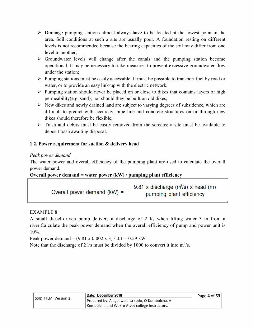
Overall power demand = water power (kW) / pumping plant efficiency
EXAMPLE 8
A small diesel-driven pump delivers a discharge of 2 l/s when lifting water 3 m from a
river.Calculate the peak power demand when the overall efficiency of pump and power unit is
10%.
Peak power demand = (9.81 x 0.002 x 3) / 0.1 = 0.59 kW
Note that the discharge of 2 l/s must be divided by 1000 to convert it into m3/s.
SSID TTLM, Version 2
Date: December 2018 Page 5 of 53 Prepared by: Alage, wolaita sodo, O-Kombolcha, A-
Kombolcha and Wekro Atvet college Instructors.
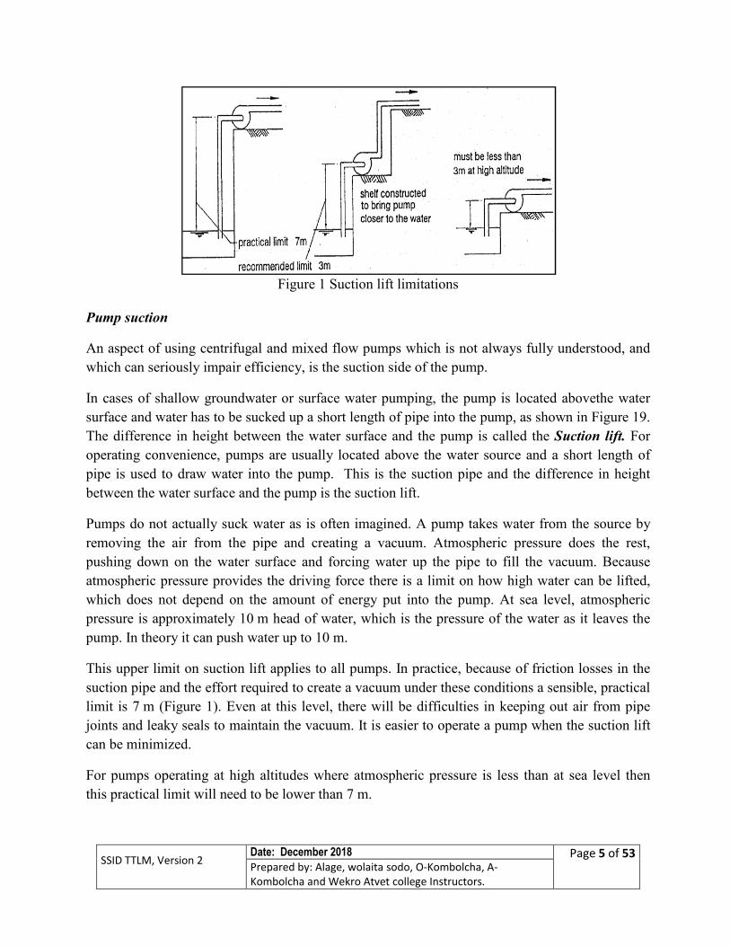
Figure 1 Suction lift limitations
Pump suction
An aspect of using centrifugal and mixed flow pumps which is not always fully understood, and
which can seriously impair efficiency, is the suction side of the pump.
In cases of shallow groundwater or surface water pumping, the pump is located abovethe water
surface and water has to be sucked up a short length of pipe into the pump, as shown in Figure 19.
The difference in height between the water surface and the pump is called the Suction lift. For
operating convenience, pumps are usually located above the water source and a short length of
pipe is used to draw water into the pump. This is the suction pipe and the difference in height
between the water surface and the pump is the suction lift.
Pumps do not actually suck water as is often imagined. A pump takes water from the source by
removing the air from the pipe and creating a vacuum. Atmospheric pressure does the rest,
pushing down on the water surface and forcing water up the pipe to fill the vacuum. Because
atmospheric pressure provides the driving force there is a limit on how high water can be lifted,
which does not depend on the amount of energy put into the pump. At sea level, atmospheric
pressure is approximately 10 m head of water, which is the pressure of the water as it leaves the
pump. In theory it can push water up to 10 m.
This upper limit on suction lift applies to all pumps. In practice, because of friction losses in the
suction pipe and the effort required to create a vacuum under these conditions a sensible, practical
limit is 7 m (Figure 1). Even at this level, there will be difficulties in keeping out air from pipe
joints and leaky seals to maintain the vacuum. It is easier to operate a pump when the suction lift
can be minimized.
For pumps operating at high altitudes where atmospheric pressure is less than at sea level then
this practical limit will need to be lower than 7 m.
SSID TTLM, Version 2
Date: December 2018 Page 6 of 53 Prepared by: Alage, wolaita sodo, O-Kombolcha, A-
Kombolcha and Wekro Atvet college Instructors.
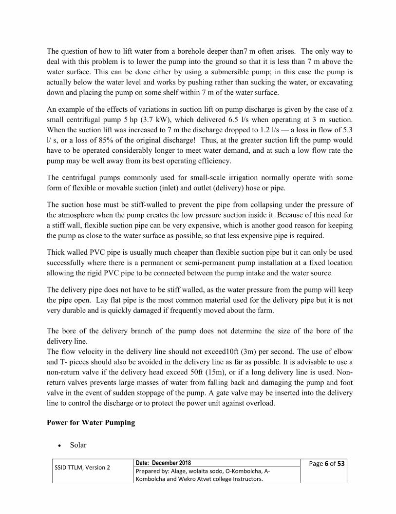
The question of how to lift water from a borehole deeper than7 m often arises. The only way to
deal with this problem is to lower the pump into the ground so that it is less than 7 m above the
water surface. This can be done either by using a submersible pump; in this case the pump is
actually below the water level and works by pushing rather than sucking the water, or excavating
down and placing the pump on some shelf within 7 m of the water surface.
An example of the effects of variations in suction lift on pump discharge is given by the case of a
small centrifugal pump 5 hp (3.7 kW), which delivered 6.5 l/s when operating at 3 m suction.
When the suction lift was increased to 7 m the discharge dropped to 1.2 l/s — a loss in flow of 5.3
l/ s, or a loss of 85% of the original discharge! Thus, at the greater suction lift the pump would
have to be operated considerably longer to meet water demand, and at such a low flow rate the
pump may be well away from its best operating efficiency.
The centrifugal pumps commonly used for small-scale irrigation normally operate with some
form of flexible or movable suction (inlet) and outlet (delivery) hose or pipe.
The suction hose must be stiff-walled to prevent the pipe from collapsing under the pressure of
the atmosphere when the pump creates the low pressure suction inside it. Because of this need for
a stiff wall, flexible suction pipe can be very expensive, which is another good reason for keeping
the pump as close to the water surface as possible, so that less expensive pipe is required.
Thick walled PVC pipe is usually much cheaper than flexible suction pipe but it can only be used
successfully where there is a permanent or semi-permanent pump installation at a fixed location
allowing the rigid PVC pipe to be connected between the pump intake and the water source.
The delivery pipe does not have to be stiff walled, as the water pressure from the pump will keep
the pipe open. Lay flat pipe is the most common material used for the delivery pipe but it is not
very durable and is quickly damaged if frequently moved about the farm.
The bore of the delivery branch of the pump does not determine the size of the bore of the
delivery line.
The flow velocity in the delivery line should not exceed10ft (3m) per second. The use of elbow
and T- pieces should also be avoided in the delivery line as far as possible. It is advisable to use a
non-return valve if the delivery head exceed 50ft (15m), or if a long delivery line is used. Non-
return valves prevents large masses of water from falling back and damaging the pump and foot
valve in the event of sudden stoppage of the pump. A gate valve may be inserted into the delivery
line to control the discharge or to protect the power unit against overload.
Power for Water Pumping
Solar
SSID TTLM, Version 2
Date: December 2018 Page 7 of 53 Prepared by: Alage, wolaita sodo, O-Kombolcha, A-
Kombolcha and Wekro Atvet college Instructors.
Wind
Water
Gasoline
Hand Pumps
1.3. Selecting Irrigation system before pumping
Small-scale pumped irrigation systems are made up of the following components
Water source;
Pump and power unit;
Distribution system; and
Method of irrigation
The water source, the distribution system and the method of irrigation determine the energy
demand. The pump and power unit provide the energy supply. The amount of water abstracted
and the height through which it must be lifted from the river or borehole add to the energy
demand.
The pump may be driven by a power unit such as a diesel or petrol engine, or an electric motor. In
some special cases solar or wind power, or even hand or animal power, may be used to provide
the power source for the pump, but they are not so common and are generally limited to very
small irrigated plots.
The distribution system conveys water from the pump to the fields and may consist of pipes or
open channels. Some systems are a combination of both. The choice of distribution system has a
significant effect on the energy demand.
The method of irrigation may be surface, sprinkler or trickle irrigation. This may also affect the
choice of distribution system and is also significant in determining the energy demand. Surface
irrigation may be supplied by either pipe or open channel systems. Sprinkler and trickle irrigation
systems would normally use piped distribution systems.
Topography characteristic: is a major factor affecting irrigation, particularly surface irrigation.
Of general concern are the location and elevation of the water supply relative to the field
boundaries, the area and configuration of the fields, and access by roads, utility lines (gas,
electricity, water, etc.), and migrating herds whether wild or domestic. Field slope and its
uniformity are two of the most important topographical factors. Surface systems, for instance,
require uniform grades in the 0-5 percent range.
SSID TTLM, Version 2
Date: December 2018 Page 8 of 53 Prepared by: Alage, wolaita sodo, O-Kombolcha, A-
Kombolcha and Wekro Atvet college Instructors.
The heart of most irrigation systems is a pump. To make an irrigation system as efficient as
possible, the pump must be selected to match the requirements of the water source, the water
piping system and the irrigation equipment.
Pumps used for irrigation include centrifugal, deep well turbine, submersible and propeller
pumps. Actually, turbine, submersible and propeller pumps are special forms of a centrifugal
pump. However, their names are common in the industry. In this circular the term centrifugal
pump will refer to any pump located above the water surface and using a suction pipe.
Before selecting an irrigation pump, a careful and complete inventory of the conditions under
which the pump will operate must take place. The inventory must include:
The source of water (well, river, pond, etc.)
The required pumping flow rate
The total suction head
The total dynamic head
There usually is no choice when it comes to the source of the water; it is either surface water or
well water and availability will be determined by the local geology and hydrologic conditions.
However, the flow rate and total dynamic head will be determined by the type of irrigation
system, the distance from the water source and the size of the piping system.
Basic Pump Operating Characteristics
"Head" is a term commonly used with pumps. Head refers to the height of a vertical column of
water. Pressure and head are interchangeable concepts in irrigation, because a column of water
2.31 feet high is equivalent to 1 pound per square inch (PSI) of pressure. The total head of a pump
is composed of several types of head that help define the pump's operating characteristics.
Total Dynamic Head: the total dynamic head of a pump is the sum of the total static head, the
pressure head, the friction head, and the velocity head. The total static head is the total vertical
distance the pump must lift the water. When pumping from a well, it would be the distance from
the pumping water level in the well to the ground surface plus the vertical distance the water is
lifted from the ground surface to the discharge point. When pumping from an open water surface
it would be the total vertical distance from the water surface to the discharge point.
Pressure Head: sprinkler and drip irrigation systems require pressure to operate. Center pivot
systems require a certain pressure at the pivot point to distribute the water properly. The pressure
SSID TTLM, Version 2
Date: December 2018 Page 9 of 53 Prepared by: Alage, wolaita sodo, O-Kombolcha, A-
Kombolcha and Wekro Atvet college Instructors.
head at any point where a pressure gage is located can be converted from pounds per square inch
(PSI) to feet of head by multiplying by 2.31. For example, 20 PSI is equal to 20 times 2.31 or 46.2
feet of head. Most city water systems operate at 50 to 60 PSI, which, as illustrated in Table 1,
explains why the centers of most city water towers are about 130 feet above the ground.
Friction Head: Friction head is the energy loss or pressure decrease due to friction when water
flows through pipe networks. The velocity of the water has a significant effect on friction loss.
Loss of head due to friction occurs when water flows through straight pipe sections, fittings,
valves, around corners, and where pipes increase or decrease in size. Values for these losses can
be calculated or obtained from friction loss tables. The friction head for a piping system is the
sum of all the friction losses.
Velocity Head: Velocity head is the energy of the water due to its velocity. This is a very small
amount of energy and is usually negligible when computing losses in an irrigation system.
Suction Head: A pump operating above a water surface is working with a suction head. The
suction head includes not only the vertical suction lift, but also the friction losses through the
pipe, elbows, foot valves and other fittings on the suction side of the pump. There is an allowable
limit to the suction head on a pump and the net positive suction head (NPSH) of a pump sets that
limit.
The theoretical maximum height that water can be lifted using suction is 33 feet. Through
controlled laboratory tests, manufacturers determine the NPSH curve for their pumps. The NPSH
curve will increase with increasing flow rate through the pump. At a certain flow rate, the NPSH
is subtracted from 33 feet to determine the maximum suction head at which that pump will
operate. For example, if a pump requires a minimum NPSH of 20 feet the pump would have a
maximum suction head of 13 feet. Due to suction pipeline friction losses, a pump rated for a
maximum suction head of 13 feet may effectively lift water only 10 feet. To minimize the suction
pipeline friction losses, the suction pipe should have a larger diameter than the discharge pipe.
Operating a pump with suction lift greater than it was designed for, or under conditions with
excessive vacuum at some point in the impeller, may cause cavitation. Cavitation is the implosion
of bubbles of air and water vapor and makes a very distinct noise like gravel in the pump. The
implosion of numerous bubbles will eat away at an impeller and it eventually will be filled with
holes.
SSID TTLM, Version 2
Date: December 2018 Page 10 of 53 Prepared by: Alage, wolaita sodo, O-Kombolcha, A-
Kombolcha and Wekro Atvet college Instructors.
Self-Check 1 Written Test
Name: _________________________ Date: _______________
Directions: Answer all the questions listed below. Illustrations may be necessary to aid some
explanations/answers
1. List the component of small-scale irrigation by pumping? 5pts
2. What is the influence of topography on irrigation system by pumping? 5pts
3. What are the basic pump operating characteristics? 5pts
Note: Satisfactory rating –7.5 points and above Unsatisfactory - below 7.5 points
You can ask your teacher for the copy of the correct answer.
Information Sheet-2 Select small motorized and manual irrigation pumps
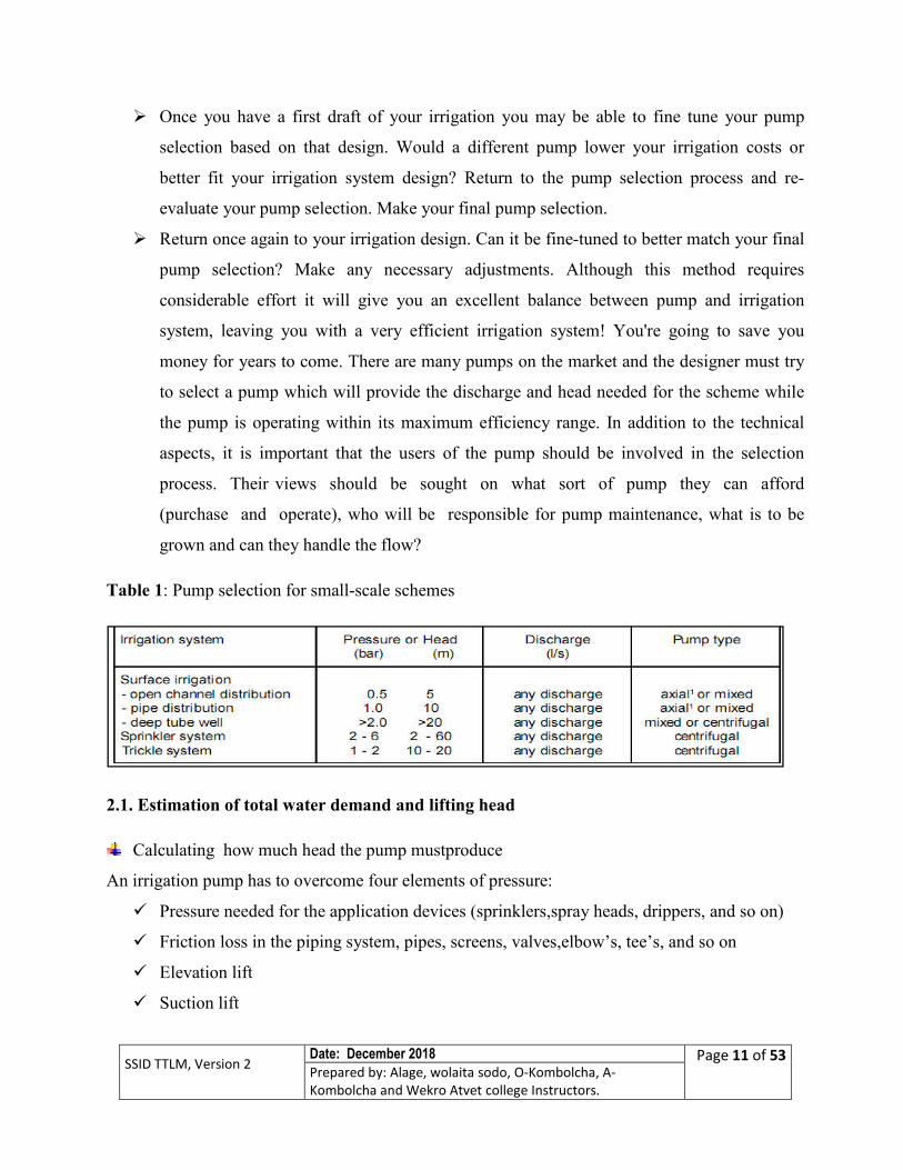
Pump selection is the process of choosing the most suitable pump for a particular irrigation
system. The performance requirements of the water system must be specified and the pump type
must be selected. Alternate pumps that meet the requirements of the system also should be
specified. Normally, the most suitable pump is chosen from these pumps considering economic
factors.
Here's the basic procedure to follow if you're selecting a pump for a new irrigation system.
Decide on the type of pump that best fits your needs, end-suction centrifugal, submersible,
turbine, jet pump, etc.
Estimate your flow (lit/sec) and pressure (m of head) requirements. The remainder of this
page will explain and demonstrate how to do this.
Research the available pump models and select a preliminary pump model that meets the
requirements you established above.
Create a first draft irrigation design. The irrigation should be designed for the flow and
pressure the pump will produce.
SSID TTLM, Version 2
Date: December 2018 Page 11 of 53 Prepared by: Alage, wolaita sodo, O-Kombolcha, A-
Kombolcha and Wekro Atvet college Instructors.
Once you have a first draft of your irrigation you may be able to fine tune your pump
selection based on that design. Would a different pump lower your irrigation costs or
better fit your irrigation system design? Return to the pump selection process and re-
evaluate your pump selection. Make your final pump selection.
Return once again to your irrigation design. Can it be fine-tuned to better match your final
pump selection? Make any necessary adjustments. Although this method requires
considerable effort it will give you an excellent balance between pump and irrigation
system, leaving you with a very efficient irrigation system! You're going to save you
money for years to come. There are many pumps on the market and the designer must try
to select a pump which will provide the discharge and head needed for the scheme while
the pump is operating within its maximum efficiency range. In addition to the technical
aspects, it is important that the users of the pump should be involved in the selection
process. Their views should be sought on what sort of pump they can afford
(purchase and operate), who will be responsible for pump maintenance, what is to be
grown and can they handle the flow?
Table 1: Pump selection for small-scale schemes
2.1. Estimation of total water demand and lifting head
Calculating how much head the pump mustproduce
An irrigation pump has to overcome four elements of pressure:
Pressure needed for the application devices (sprinklers,spray heads, drippers, and so on)
Friction loss in the piping system, pipes, screens, valves,elbow’s, tee’s, and so on
Elevation lift
Suction lift
SSID TTLM, Version 2
Date: December 2018 Page 12 of 53 Prepared by: Alage, wolaita sodo, O-Kombolcha, A-
Kombolcha and Wekro Atvet college Instructors.
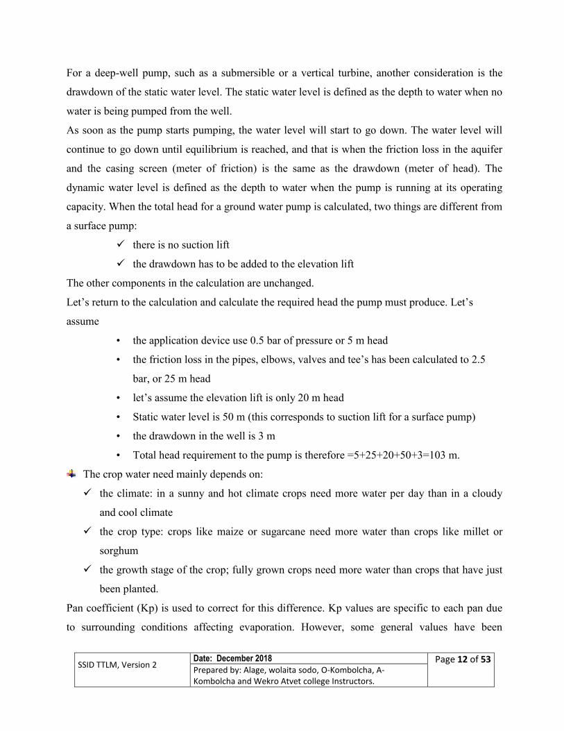
For a deep-well pump, such as a submersible or a vertical turbine, another consideration is the
drawdown of the static water level. The static water level is defined as the depth to water when no
water is being pumped from the well.
As soon as the pump starts pumping, the water level will start to go down. The water level will
continue to go down until equilibrium is reached, and that is when the friction loss in the aquifer
and the casing screen (meter of friction) is the same as the drawdown (meter of head). The
dynamic water level is defined as the depth to water when the pump is running at its operating
capacity. When the total head for a ground water pump is calculated, two things are different from
a surface pump:
there is no suction lift
the drawdown has to be added to the elevation lift
The other components in the calculation are unchanged.
Let’s return to the calculation and calculate the required head the pump must produce. Let’s
assume
• the application device use 0.5 bar of pressure or 5 m head
• the friction loss in the pipes, elbows, valves and tee’s has been calculated to 2.5
bar, or 25 m head
• let’s assume the elevation lift is only 20 m head
• Static water level is 50 m (this corresponds to suction lift for a surface pump)
• the drawdown in the well is 3 m
• Total head requirement to the pump is therefore =5+25+20+50+3=103 m.
The crop water need mainly depends on:
the climate: in a sunny and hot climate crops need more water per day than in a cloudy
and cool climate
the crop type: crops like maize or sugarcane need more water than crops like millet or
sorghum
the growth stage of the crop; fully grown crops need more water than crops that have just
been planted.
Pan coefficient (Kp) is used to correct for this difference. Kp values are specific to each pan due
to surrounding conditions affecting evaporation. However, some general values have been
SSID TTLM, Version 2
Date: December 2018 Page 13 of 53 Prepared by: Alage, wolaita sodo, O-Kombolcha, A-
Kombolcha and Wekro Atvet college Instructors.
recommended where a Kp value is lacking for a pan. For example, a pan in a dry fallow area with
light winds (< 2 m/s) will have Kp values from 0.55 to 0.75, depending on humidity levels (Allen
et al. 1998). The minimum Kp value reported for any Class A pan was 0.85 (Allen et al. 1998).
Pan evaporation corrected by a Kp value allows ETo to be estimated:
ETo pan = Kp * Epan
The label ETo pan will be used to discriminate between ET calculated using meteorological data
(ETo) and ET calculated from pan data (ETo pan). A crop factor is then used to describe the
proportion of water used by a crop or specific growth stage of a crop relative to ETo pan, and
allows a crops water requirement to be estimated by:
Crop water requirements = Crop factor * ETo pan
Scheme irrigation efficiency:
The scheme irrigation efficiency (e in %) is that part of the water pumped or diverted through
the scheme inlet which is used effectively by the plants. The scheme irrigation efficiency can be
sub-divided into:
the conveyance efficiency (ec) which represents the efficiency of water transport in
canals, and
the field application efficiency (ea) which represents the efficiency of water application
in the field.
The conveyance efficiency (ec) mainly depends on the length of the canals, the soil type or
permeability of the canal banks and the condition of the canals.
In large irrigation schemes more water is lost than in small schemes, due to a longer canal system.
From canals in sandy soils more water is lost than from canals in heavy clay soils. When canals
are lined with bricks, plastic or concrete, only very little water is lost. If canals are badly
maintained, bund breaks are not repaired properly and rats dig holes, a lot of water is lost.
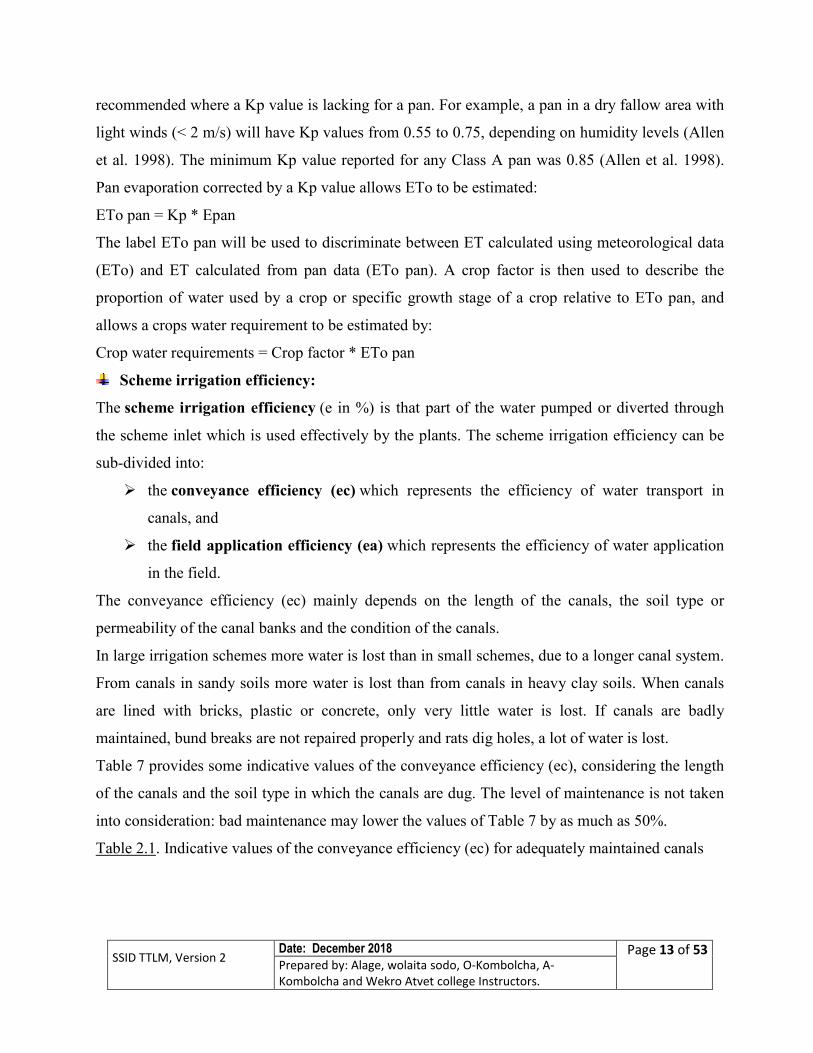
Table 7 provides some indicative values of the conveyance efficiency (ec), considering the length
of the canals and the soil type in which the canals are dug. The level of maintenance is not taken
into consideration: bad maintenance may lower the values of Table 7 by as much as 50%.
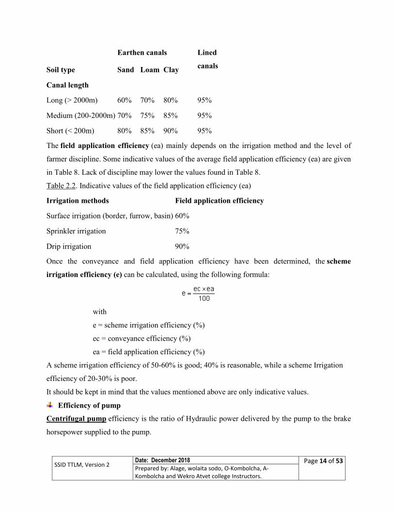
Table 2.1. Indicative values of the conveyance efficiency (ec) for adequately maintained canals
SSID TTLM, Version 2
Date: December 2018 Page 14 of 53 Prepared by: Alage, wolaita sodo, O-Kombolcha, A-
Kombolcha and Wekro Atvet college Instructors.
The field application efficiency (ea) mainly depends on the irrigation method and the level of
farmer discipline. Some indicative values of the average field application efficiency (ea) are given
in Table 8. Lack of discipline may lower the values found in Table 8.
Table 2.2. Indicative values of the field application efficiency (ea)
Irrigation methods Field application efficiency
Surface irrigation (border, furrow, basin) 60%
Sprinkler irrigation 75%
Drip irrigation 90%
Once the conveyance and field application efficiency have been determined, the scheme
irrigation efficiency (e) can be calculated, using the following formula:
with
e = scheme irrigation efficiency (%)
ec = conveyance efficiency (%)
ea = field application efficiency (%)
A scheme irrigation efficiency of 50-60% is good; 40% is reasonable, while a scheme Irrigation
efficiency of 20-30% is poor.
It should be kept in mind that the values mentioned above are only indicative values.
Efficiency of pump
Centrifugal pump efficiency is the ratio of Hydraulic power delivered by the pump to the brake
horsepower supplied to the pump.
Earthen canals Lined
canals Soil type Sand Loam Clay
Canal length
Long (> 2000m) 60% 70% 80% 95%
Medium (200-2000m) 70% 75% 85% 95%
Short (< 200m) 80% 85% 90% 95%
SSID TTLM, Version 2
Date: December 2018 Page 15 of 53 Prepared by: Alage, wolaita sodo, O-Kombolcha, A-
Kombolcha and Wekro Atvet college Instructors.
Hydraulic Power (Power Output from Pump):
Centrifugal Pump consumes energy to develop the discharge pressure and to deliver flow. Therefore Hydraulic Horsepower of the Pump depends on these two parameters.
Power Output from Pump = (P2 – P1) * Q
P2: Pump Discharge pressure in N/m2
P1: Pump suction pressure in N/m2
Q: Flow delivered by pump in m3/s
Brake Horse Power (Power Input to Pump):
This is the power given to the pump through Electric Motor. Power output from the electric driver is calculated by the formula
Power Input to Pump = 1.732 * V * I * PF * Motor Efficiency * Coupling Efficiency
V: Measured Voltage of Motor in Volt
I: Measured Current of Motor in Ampere
PF: Power Factor Centrifugal pump efficiency equation
Centrifugal pump efficiency = Power Output from Pump/ Power Input to Pump * 100
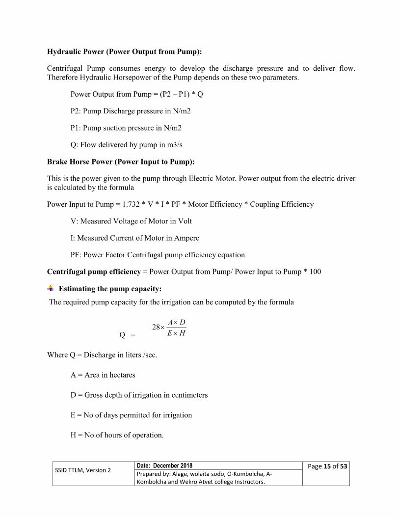
Estimating the pump capacity:
The required pump capacity for the irrigation can be computed by the formula
Q = HE
DA
28
Where Q = Discharge in liters /sec.
A = Area in hectares
D = Gross depth of irrigation in centimeters
E = No of days permitted for irrigation
H = No of hours of operation.
SSID TTLM, Version 2
Date: December 2018 Page 16 of 53 Prepared by: Alage, wolaita sodo, O-Kombolcha, A-
Kombolcha and Wekro Atvet college Instructors.
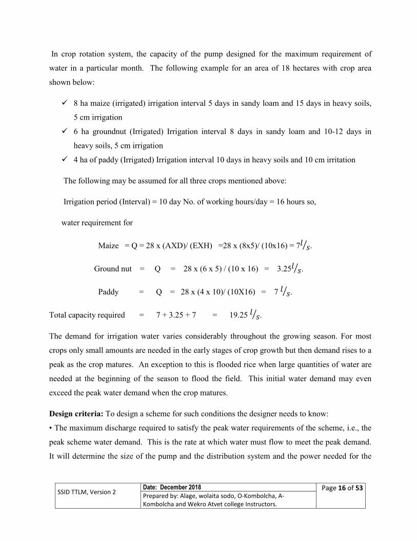
In crop rotation system, the capacity of the pump designed for the maximum requirement of
water in a particular month. The following example for an area of 18 hectares with crop area
shown below:
8 ha maize (irrigated) irrigation interval 5 days in sandy loam and 15 days in heavy soils,
5 cm irrigation
6 ha groundnut (Irrigated) Irrigation interval 8 days in sandy loam and 10-12 days in
heavy soils, 5 cm irrigation
4 ha of paddy (Irrigated) Irrigation interval 10 days in heavy soils and 10 cm irritation
The following may be assumed for all three crops mentioned above:
Irrigation period (Interval) = 10 day No. of working hours/day = 16 hours so,
water requirement for
Maize = Q = 28 x (AXD)/ (EXH) =28 x (8x5)/ (10x16) = 7� �� .
Ground nut = Q = 28 x (6 x 5) / (10 x 16) = 3.25� �� .
Paddy = Q = 28 x (4 x 10)/ (10X16) = 7 � �� .
Total capacity required = 7 + 3.25 + 7 = 19.25 � �� .
The demand for irrigation water varies considerably throughout the growing season. For most
crops only small amounts are needed in the early stages of crop growth but then demand rises to a
peak as the crop matures. An exception to this is flooded rice when large quantities of water are
needed at the beginning of the season to flood the field. This initial water demand may even
exceed the peak water demand when the crop matures.
Design criteria: To design a scheme for such conditions the designer needs to know:
• The maximum discharge required to satisfy the peak water requirements of the scheme, i.e., the
peak scheme water demand. This is the rate at which water must flow to meet the peak demand.
It will determine the size of the pump and the distribution system and the power needed for the
SSID TTLM, Version 2
Date: December 2018 Page 17 of 53 Prepared by: Alage, wolaita sodo, O-Kombolcha, A-
Kombolcha and Wekro Atvet college Instructors.
scheme. The pipes or channels must be large enough to carry this discharge and the pump and
power unit must be powerful enough to deliver the discharge at the pressure required. It is useful
at this point to consider the possibility of future extensions to the scheme. If this is a possibility,
then the designer may oversize the current scheme to allow for this.
• The volume of water required over the season, i.e., the seasonal scheme water demand. This is
the total amount of water needed over the growing season and the designer must be satisfied that
there is enough water available to meet the total water demand for growing the crops. From this
the energy demand for pumping over the growing season can be determined.
System capacity depends on the following:
Crop water requirements, determined by crop type, stage of growth, and climatic
conditions;
Field application efficiency; and
Distribution efficiency.
2.2. Identifying available power source based on local conditions and economic
Considerations.
Power for Water Pumping
Solar--solar technology is very well suited to pumping water, even more so than the
traditional windmill. A typical system includes one or more solar panels, an efficient 12
volt DC pump, a controller (with float switches), and a "linear current booster" (more
about this later). As long as it's daytime and the float switches show that the water source
is not empty and the cistern in the house is not overflowing, the pump will run. The linear
current booster allows the pump to run even if it's cloudy out.
Wind--The traditional windmill is still useful technology. The pump is directly coupled
to the wind generator. The only problem comes if there is no wind for a few days at a
time, and with maintenance. The leather seals on this sort of pump wear out and require
replacement. The Bow Jon windmill system uses pressurized air to pump water, and
requires very little maintenance. It can also be used to generate power. Other systems
SSID TTLM, Version 2
Date: December 2018 Page 18 of 53 Prepared by: Alage, wolaita sodo, O-Kombolcha, A-
Kombolcha and Wekro Atvet college Instructors.
have been built using an electric wind generator, linear current booster, and pump, as
described in the solar section above.
Water--Yes, water can be used to pump water. The device involved is called a "water
ram." It uses your local stream's water pressure to move a fraction of the total stream flow
uphill--as much as 30 times the total fall. Water rams can be purchased, or built at home
with PVC pipe and valves. Look for more information on this here in the future.
Gasoline-- A waste of resources. Avoid it if possible.
Hand Pumps--Better than not having water, if you have no resources available. Or if you
can get your kids to do it. Different hand pumps are available commercially (my grandma
had one), or pumps can be constructed than run on foot power instead of hand. There are
different types of power unit: some of them are as follow internal combustion engines,
electric motors, solar, and wind in addition to human/animal powered pumps.
A. Internal combustion engines
Many small irrigation schemes do not have access to electricity and so rely on petrol (spark
ignition) engines or diesel (compression ignition) engines to drive the pumps. These engines have
a good weight: power output ratio, and are compact in size and relatively cheap due to mass
production techniques. Diesel engines tend to be heavier and more robust than petrol engines and
are more expensive to buy. However, they are also more efficient to run and if operated and
maintained properly they have a longer working life and are more reliable than petrol. In some
countries petrol-driven pumps have needed replacing after only 3 years of operation. Diesel
pumps operating in similar conditions could be expected to last at least 6 years. However, it must
not be forgotten that engine life is not just measured in years, it is measured in hours of operation
and its useful life depends on how well it is operated and serviced. There are cases in developing
countries where diesel pumps have been in continual use for 30 years and more. A diesel-engine
pump can be up to four times as heavy as a petrol-engine pump of equivalent power, and so if
portability is important a petrol pump may be the answer.
B. Electric motors
Electric motors are very efficient in energy use (75 - 85%) and can be used to drive all sizes and
types of pumps. The main drawback is the reliance on a power supply which is beyond the
SSID TTLM, Version 2
Date: December 2018 Page 19 of 53 Prepared by: Alage, wolaita sodo, O-Kombolcha, A-
Kombolcha and Wekro Atvet college Instructors.
control of the farmer, and which in many places is unreliable. Inevitably electrical power supplies
usually fail when they are most needed. Heavy demands occur when crops need most water and
so a power failure over several days can have disastrous consequences for a crop. When using
trickle irrigation on light sandy soils, serious crop losses may well occur after only a few days
without power.
C. Solar Powered Water Lifting For Irrigation
By definition solar energy is “the conversion of sunlight into usable energy forms”. The main
solar technologies are photovoltaics’ (PV), solar thermal electricity and solar heating and cooling.
For agricultural production and processing, solar energy is an important energy source, in
particular for irrigation. Solar Powered Irrigation system is a complete system which provides
fresh water from a well and reservoir for use in livestock, domestic use and industrial or
agriculture. The implementation of solar powered irrigation helps overcoming the risk from
fluctuations in both fuel and supply prices, and instead guarantees stable and reliable on farm
energy supply. Therewith, crop losses that result from insufficient irrigation are avoided. How It
Works: The has three main parts: the PV panel, an 80W solar panel to convert sunlight into
electrical energy; the motor, a specially designed DC motor to use the electrical energy to turn the
flywheel; and the pump, a reciprocal piston pump to draw water out of a well, river or lake.
Benefits of Solar Powered Water Lifting For Irrigation
No fuel or electricity costs
Designed with durability & maintenance in mind
Lifts 2,500 liters/hr at 1m, 1,600 liters/hour at 6m
Pumps enough to irrigate around ½ an acre
Farmer-fixable (similar complexity to a bicycle)
Can lift water over 10m
Removable PV panel reduces theft risk
Retails at $650
SSID TTLM, Version 2
Date: December 2018 Page 20 of 53 Prepared by: Alage, wolaita sodo, O-Kombolcha, A-
Kombolcha and Wekro Atvet college Instructors.
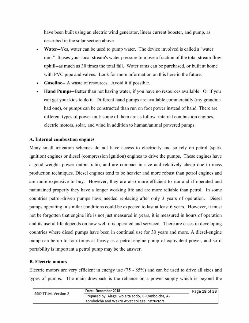
Technical Performance: The SF1 can lift over 12,000 liters of water a day, with best performance
at low pumping heads, and slower flow rates with increasing head, as illustrated below. A manual
switch allows for pumping early in the morning and late in the day.
Figure 2.1 solar powered pump
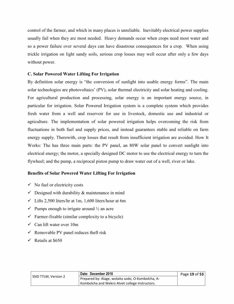
Designed for shallow and surface water pumping the FS1 for retrieving lake and river water.
Figure 2.2 flow rate
The pump is efficient at both sucking and discharging across the head range; therefore,
performance is not compromised by the position of the pump along the length of pipe.
The SF1 is intended for farm-wide irrigation and is able to pump over 100m with minimal loss of
flow. This makes it ideally suited to pumping into elevated storage tanks or directly into drip
irrigation systems.
SSID TTLM, Version 2
Date: December 2018
Prepared by: Alage, wolaita sodo, OKombolcha and Wekro Atvet college Instructors.
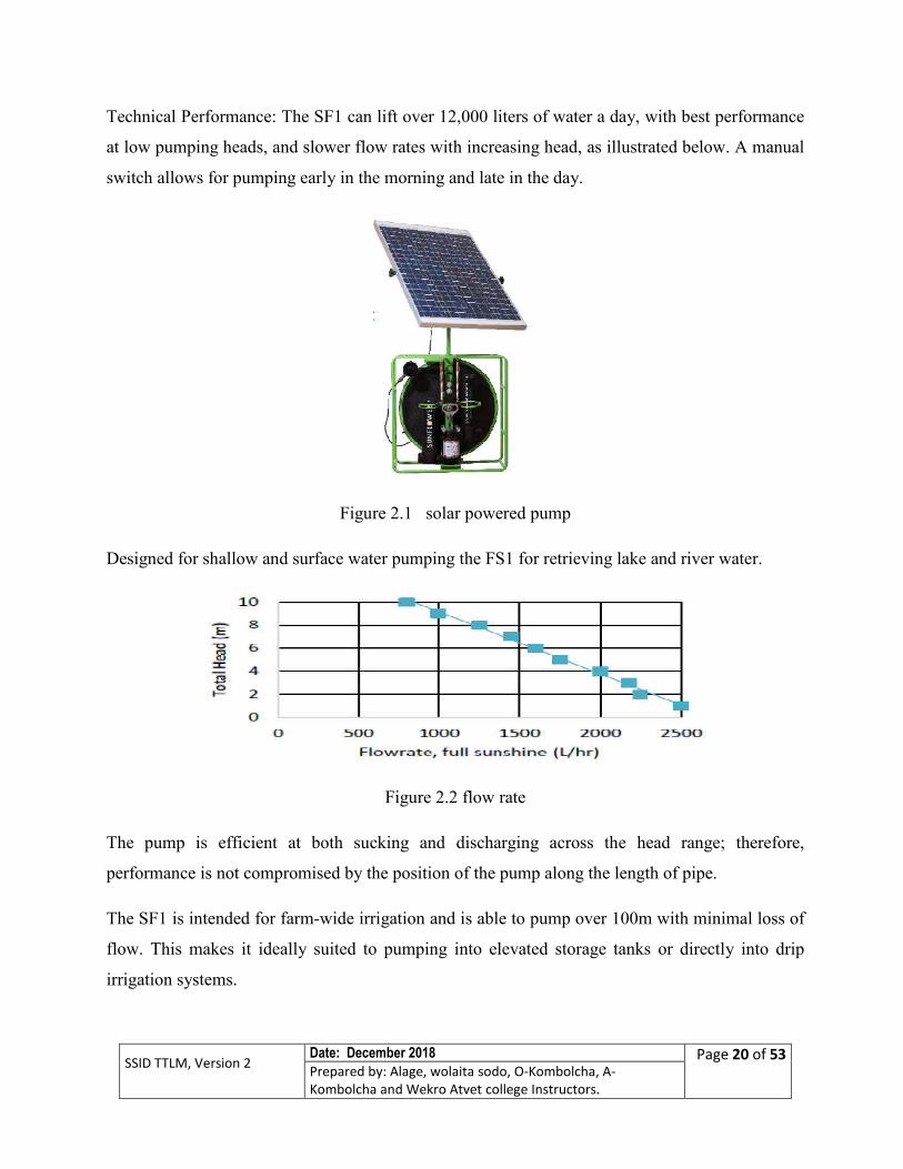
D. Treadle pump
Low cost water lifting technologies are important tools for resource poor farmers. They are
mostly applicable in a condition where the lift requirement is less than 7 meters above the water
surface.
Figure 2.3.
The pump is operated by moving two pedals while standing on the pump and can be operated for
several hours as opposed to the more arduous process of hand pumping and hand watering. From
low cost human powered pumps treadle pump
surface ponds and shallow wells as well.
The main difference is the positioning of the valves. A suction pump can merely raise water from
a source, which then spills over for gravity irrigation. The pump t
level. The pumps can pump up to about 12 meters head, depending on the distance from the water
source.
Capacity: The treadle pump is a low
seven cubic meters of water per hour from ponds, wells and streams up to 7m deep at a lift of 4.5
meters; the treadle pump has a discharge of 1.7 L/sec and can irrigate 0.5 ha.
Date: December 2018
Prepared by: Alage, wolaita sodo, O-Kombolcha, A-Kombolcha and Wekro Atvet college Instructors.
Low cost water lifting technologies are important tools for resource poor farmers. They are
mostly applicable in a condition where the lift requirement is less than 7 meters above the water
Figure 2.3. Components of treadle pump
The pump is operated by moving two pedals while standing on the pump and can be operated for
several hours as opposed to the more arduous process of hand pumping and hand watering. From
low cost human powered pumps treadle pump is the most appropriate for extracting water from
surface ponds and shallow wells as well.
The main difference is the positioning of the valves. A suction pump can merely raise water from
a source, which then spills over for gravity irrigation. The pump therefore has to be at the highest
level. The pumps can pump up to about 12 meters head, depending on the distance from the water
: The treadle pump is a low-lift, high-capacity human-powered pump. It can lift five to
ater per hour from ponds, wells and streams up to 7m deep at a lift of 4.5
meters; the treadle pump has a discharge of 1.7 L/sec and can irrigate 0.5 ha.
Page 21 of 53
Low cost water lifting technologies are important tools for resource poor farmers. They are
mostly applicable in a condition where the lift requirement is less than 7 meters above the water
The pump is operated by moving two pedals while standing on the pump and can be operated for
several hours as opposed to the more arduous process of hand pumping and hand watering. From
is the most appropriate for extracting water from
The main difference is the positioning of the valves. A suction pump can merely raise water from
herefore has to be at the highest
level. The pumps can pump up to about 12 meters head, depending on the distance from the water
powered pump. It can lift five to
ater per hour from ponds, wells and streams up to 7m deep at a lift of 4.5
SSID TTLM, Version 2
Date: December 2018
Prepared by: Alage, wolaita sodo, OKombolcha and Wekro Atvet college Instructors.
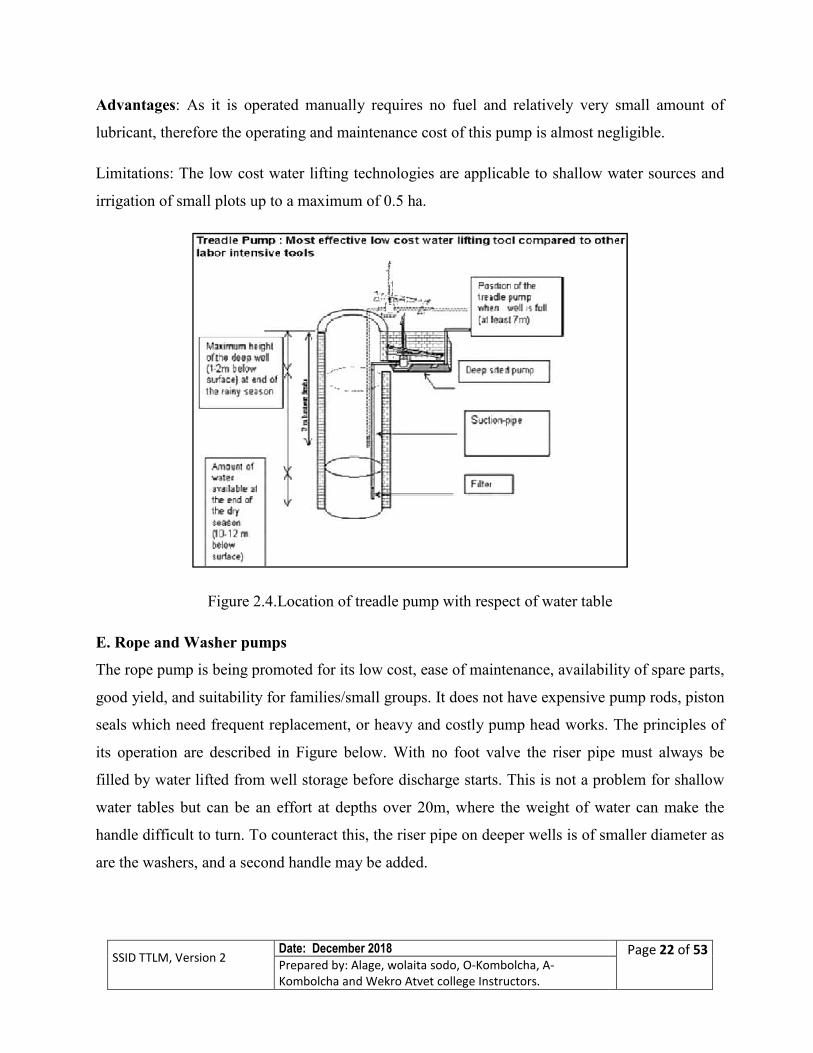
Advantages: As it is operated manually requires no fuel and relatively very small amount of
lubricant, therefore the operating and maintenance cost of this pump is almost negligible.
Limitations: The low cost water lifting technologies are applicable to shallow water sources and
irrigation of small plots up to a maximum of 0.5 ha.
Figure 2.4.Location
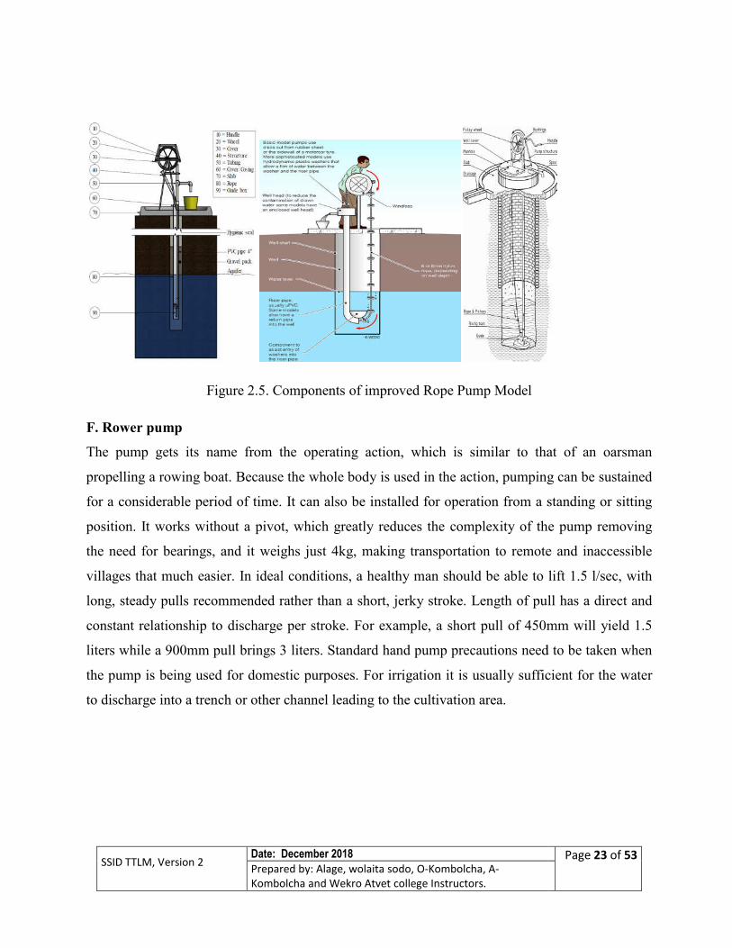
E. Rope and Washer pumps
The rope pump is being promoted for its low cost, ease of maintenance, availability of spare parts,
good yield, and suitability for families/small groups. It does not have expensive pump
seals which need frequent replacement, or heavy and costly pump head works. The principles of
its operation are described in Figure below. With no foot valve the riser pipe must always be
filled by water lifted from well storage before dischar
water tables but can be an effort at depths over 20m, where the weight of water can make the
handle difficult to turn. To counteract this, the riser pipe on deeper wells is of smaller diameter as
are the washers, and a second handle may be added.
Date: December 2018
Prepared by: Alage, wolaita sodo, O-Kombolcha, A-Kombolcha and Wekro Atvet college Instructors.
: As it is operated manually requires no fuel and relatively very small amount of
, therefore the operating and maintenance cost of this pump is almost negligible.
Limitations: The low cost water lifting technologies are applicable to shallow water sources and
irrigation of small plots up to a maximum of 0.5 ha.
Figure 2.4.Location of treadle pump with respect of water table
The rope pump is being promoted for its low cost, ease of maintenance, availability of spare parts,
good yield, and suitability for families/small groups. It does not have expensive pump
seals which need frequent replacement, or heavy and costly pump head works. The principles of
its operation are described in Figure below. With no foot valve the riser pipe must always be
filled by water lifted from well storage before discharge starts. This is not a problem for shallow
water tables but can be an effort at depths over 20m, where the weight of water can make the
handle difficult to turn. To counteract this, the riser pipe on deeper wells is of smaller diameter as
, and a second handle may be added.
Page 22 of 53
: As it is operated manually requires no fuel and relatively very small amount of
, therefore the operating and maintenance cost of this pump is almost negligible.
Limitations: The low cost water lifting technologies are applicable to shallow water sources and
of treadle pump with respect of water table
The rope pump is being promoted for its low cost, ease of maintenance, availability of spare parts,
good yield, and suitability for families/small groups. It does not have expensive pump rods, piston
seals which need frequent replacement, or heavy and costly pump head works. The principles of
its operation are described in Figure below. With no foot valve the riser pipe must always be
ge starts. This is not a problem for shallow
water tables but can be an effort at depths over 20m, where the weight of water can make the
handle difficult to turn. To counteract this, the riser pipe on deeper wells is of smaller diameter as
SSID TTLM, Version 2
Date: December 2018
Prepared by: Alage, wolaita sodo, OKombolcha and Wekro Atvet college Instructors.
Figure 2.5. Components of improved Rope Pump Model
F. Rower pump
The pump gets its name from the operating action, which is similar to that of an oarsman
propelling a rowing boat. Because the whole body is used in
for a considerable period of time. It can also be installed for operation from a standing or sitting
position. It works without a pivot, which greatly reduces the complexity of the pump removing
the need for bearings, and it weighs just 4kg, making transportation to remote and inaccessible
villages that much easier. In ideal conditions, a healthy man should be able to lift 1.5 l/sec, with
long, steady pulls recommended rather than a short, jerky stroke. Length of pull ha
constant relationship to discharge per stroke. For example, a short pull of 450mm will yield 1.5
liters while a 900mm pull brings 3 liters. Standard hand pump precautions need to be taken when
the pump is being used for domestic purposes. Fo
to discharge into a trench or other channel leading to the cultivation area.
Date: December 2018
Prepared by: Alage, wolaita sodo, O-Kombolcha, A-Kombolcha and Wekro Atvet college Instructors.
Figure 2.5. Components of improved Rope Pump Model
The pump gets its name from the operating action, which is similar to that of an oarsman
propelling a rowing boat. Because the whole body is used in the action, pumping can be sustained
for a considerable period of time. It can also be installed for operation from a standing or sitting
position. It works without a pivot, which greatly reduces the complexity of the pump removing
nd it weighs just 4kg, making transportation to remote and inaccessible
villages that much easier. In ideal conditions, a healthy man should be able to lift 1.5 l/sec, with
long, steady pulls recommended rather than a short, jerky stroke. Length of pull ha
constant relationship to discharge per stroke. For example, a short pull of 450mm will yield 1.5
liters while a 900mm pull brings 3 liters. Standard hand pump precautions need to be taken when
the pump is being used for domestic purposes. For irrigation it is usually sufficient for the water
to discharge into a trench or other channel leading to the cultivation area.
Page 23 of 53
The pump gets its name from the operating action, which is similar to that of an oarsman
the action, pumping can be sustained
for a considerable period of time. It can also be installed for operation from a standing or sitting
position. It works without a pivot, which greatly reduces the complexity of the pump removing
nd it weighs just 4kg, making transportation to remote and inaccessible
villages that much easier. In ideal conditions, a healthy man should be able to lift 1.5 l/sec, with
long, steady pulls recommended rather than a short, jerky stroke. Length of pull has a direct and
constant relationship to discharge per stroke. For example, a short pull of 450mm will yield 1.5
liters while a 900mm pull brings 3 liters. Standard hand pump precautions need to be taken when
r irrigation it is usually sufficient for the water
SSID TTLM, Version 2
Date: December 2018
Prepared by: Alage, wolaita sodo, OKombolcha and Wekro Atvet college Instructors.
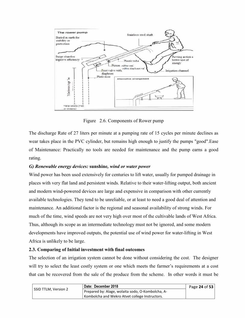
Figure 2.6. Components of Rower pump
The discharge Rate of 27 liters per minute at a pumping rate of 15 cycles per minute
wear takes place in the PVC cylinder, but remains high enough to justify the pumps "good".Ease
of Maintenance: Practically no tools are needed for maintenance and the pump earns a good
rating.
G) Renewable energy devices: sunshine
Wind power has been used extensively for centuries to lift water, usually for pumped drainage in
places with very flat land and persistent winds. Relative to their water
and modern wind-powered devices are large and
available technologies. They tend to be unreliable, or at least to need a good deal of attention and
maintenance. An additional factor is the regional and seasonal availability of strong winds. For
much of the time, wind speeds are not very high over most of the cultivable lands of West Africa.
Thus, although its scope as an intermediate technology must not be ignored, and some modern
developments have improved outputs, the potential use of wind power for water
Africa is unlikely to be large.
2.3. Comparing of Initial investment with final outcomes
The selection of an irrigation system cannot be done without considering the cost. The designer
will try to select the least costly system or one whic
that can be recovered from the sale of the produce from the scheme. In other words it must be
Date: December 2018
Prepared by: Alage, wolaita sodo, O-Kombolcha, A-Kombolcha and Wekro Atvet college Instructors.
Figure 2.6. Components of Rower pump
The discharge Rate of 27 liters per minute at a pumping rate of 15 cycles per minute
wear takes place in the PVC cylinder, but remains high enough to justify the pumps "good".Ease
of Maintenance: Practically no tools are needed for maintenance and the pump earns a good
sunshine, wind or water power
Wind power has been used extensively for centuries to lift water, usually for pumped drainage in
places with very flat land and persistent winds. Relative to their water-lifting output, both ancient
powered devices are large and expensive in comparison with other currently
available technologies. They tend to be unreliable, or at least to need a good deal of attention and
maintenance. An additional factor is the regional and seasonal availability of strong winds. For
time, wind speeds are not very high over most of the cultivable lands of West Africa.
Thus, although its scope as an intermediate technology must not be ignored, and some modern
developments have improved outputs, the potential use of wind power for water-
2.3. Comparing of Initial investment with final outcomes
The selection of an irrigation system cannot be done without considering the cost. The designer
will try to select the least costly system or one which meets the farmer’s requirements at a cost
that can be recovered from the sale of the produce from the scheme. In other words it must be
Page 24 of 53
The discharge Rate of 27 liters per minute at a pumping rate of 15 cycles per minute declines as
wear takes place in the PVC cylinder, but remains high enough to justify the pumps "good".Ease
of Maintenance: Practically no tools are needed for maintenance and the pump earns a good
Wind power has been used extensively for centuries to lift water, usually for pumped drainage in
lifting output, both ancient
expensive in comparison with other currently
available technologies. They tend to be unreliable, or at least to need a good deal of attention and
maintenance. An additional factor is the regional and seasonal availability of strong winds. For
time, wind speeds are not very high over most of the cultivable lands of West Africa.
Thus, although its scope as an intermediate technology must not be ignored, and some modern
-lifting in West
The selection of an irrigation system cannot be done without considering the cost. The designer
h meets the farmer’s requirements at a cost
that can be recovered from the sale of the produce from the scheme. In other words it must be
SSID TTLM, Version 2
Date: December 2018 Page 25 of 53 Prepared by: Alage, wolaita sodo, O-Kombolcha, A-
Kombolcha and Wekro Atvet college Instructors.
financially worthwhile to irrigate. The system capacity, the choice of technology and its
management and maintenance, determine the overall cost of the scheme. This is not just the cost
of constructing the system and buying pumps and irrigation equipment (capital cost) but also the
cost of running the system over many years (operating costs).The idea of cost-effectiveness is an
important one. Although the choice of irrigation system should involve both capital and operating
costs, sometimes the choice is not an easy one. Capital costs are easily identified sums of money
which must be paid out when installing a scheme. Operating costs are much less clear and are
spread over many years, and so there is a tendency for farmers to choose a scheme based only on
a minimum or acceptable capital cost. They may also lack the immediate cash to invest in the
more expensive systems which could save them money in operating costs in the longer term.
Overall cost: When a suitable irrigation system has been selected and a capital cost determined,
the operating costs can then be calculated. From this the overall cost can be found that is the sum
of the capital cost and the operating cost.
Overall cost = capital cost + operating cost
The finale product of irrigation system is greater than the overall cost is profitable.
Self-Check 2 Written Test
Name: _________________________ Date: _______________
Directions: Answer all the questions listed below. Illustrations may be necessary to aid some
explanations/answers.
1. The total head of a pump is composed of several types of head list and define them. (5)
2. List and explain the power sources for irrigation pump? (10)
3. What is the difference between electrical, petrol (spark ignition) engines or diesel (compression
ignition) pumps? (10)
4. Define the idea of cost-effectiveness? (5)
5. Discuss about the conveyance efficiency and application efficiency? (5)
Note: Satisfactory rating –15.25 points and above Unsatisfactory - below 15.25 points
You can ask your teacher for the copy of the correct answer.
SSID TTLM, Version 2
Date: December 2018 Page 26 of 53 Prepared by: Alage, wolaita sodo, O-Kombolcha, A-
Kombolcha and Wekro Atvet college Instructors.
Information Sheet-3
Install small motorized and manual irrigation pumps
3.1 Placing the small motorized and manual irrigation pumps
Small motor pumps refer to diesel or kerosene fueled motor pumps that have a typical size
between 0.5 and 2.5 hp, and have been optimized to use as little fuel as possible. Proper motor
pump selection can reduce fuel consumption significantly, which can lead to significant cost
reduction. New cost-efficient irrigation pumps are available in countries such as China and India.
Chinese 4HP diesel pumps can irrigate 5 ha up to heads of 6 m, consuming 0.45 liters of fuel an
hour. Chinese petrol pumps of 1.5 HP pump 3 liters per second and consume less than 0.3 liters of
gasoline per hour.
A second issue, which is often overlooked, is the design of the filter screen at the input of the
pump. In many cases, a filter screen is used that is too small, which leads to excessive resistance
for the water to be pumped through it. This can easily lead to a doubling of fuel consumption for
the same amount of water pumped.
What is the purpose of a pump?
Pumps are designed to move fluid
Pumps transfer fluid for processing
In most plants pumps are a critical part of daily operation
Setting of pumping station
The careful selection of a suitable location for a pumping station is very important in irrigation
development. Several factors have to be taken into consideration when choosing the site.
Firstly, one has to find out whether the flow is reliable in the case of a river or whether the
amount of water stored in the dam is enough to fulfill the annual irrigation requirements for the
proposed cropping program. This information is often obtained from the water authority or from
the local farmers' experiences.
Secondly, in the case of river abstraction one has to check the maximum flood level of the river
and preferably site the pumping station outside the flood level. With the limitations often imposed
by the length of the suction pipe necessary to cater for the net positive suction head, where there
are fluctuating flood levels, a portable pumping station is preferable. Such a site, however, should
be on stable soil and have enough of water depth for the suction pipe. For permanent pumping
SSID TTLM, Version 2
Date: December 2018 Page 27 of 53 Prepared by: Alage, wolaita sodo, O-Kombolcha, A-
Kombolcha and Wekro Atvet college Instructors.
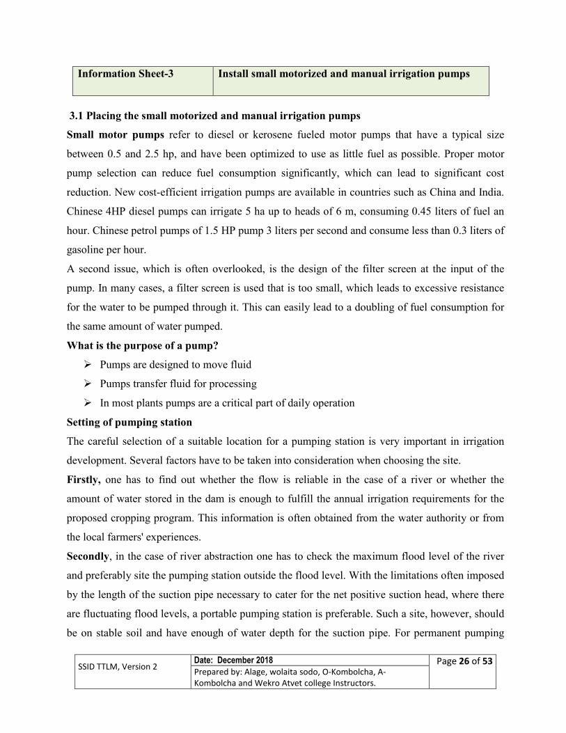
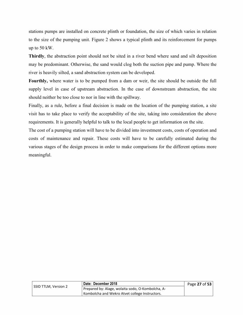
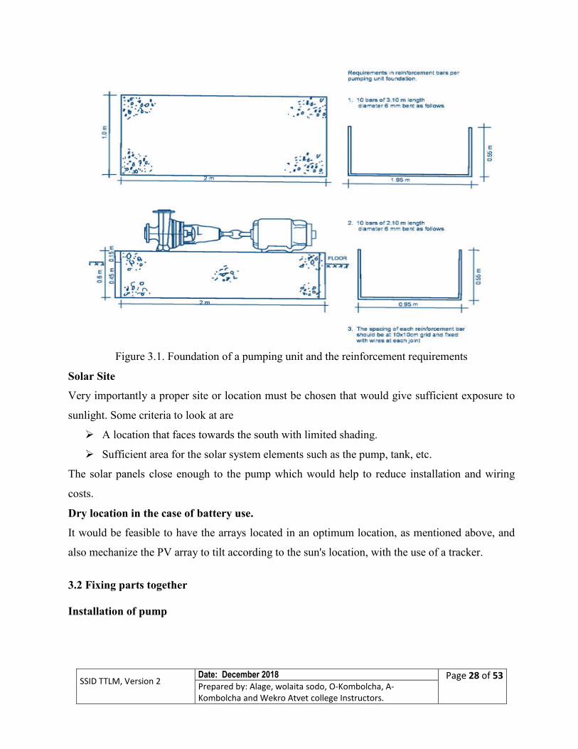
stations pumps are installed on concrete plinth or foundation, the size of which varies in relation
to the size of the pumping unit. Figure 2 shows a typical plinth and its reinforcement for pumps
up to 50 kW.
Thirdly, the abstraction point should not be sited in a river bend where sand and silt deposition
may be predominant. Otherwise, the sand would clog both the suction pipe and pump. Where the
river is heavily silted, a sand abstraction system can be developed.
Fourthly, where water is to be pumped from a dam or weir, the site should be outside the full
supply level in case of upstream abstraction. In the case of downstream abstraction, the site
should neither be too close to nor in line with the spillway.
Finally, as a rule, before a final decision is made on the location of the pumping station, a site
visit has to take place to verify the acceptability of the site, taking into consideration the above
requirements. It is generally helpful to talk to the local people to get information on the site.
The cost of a pumping station will have to be divided into investment costs, costs of operation and
costs of maintenance and repair. These costs will have to be carefully estimated during the
various stages of the design process in order to make comparisons for the different options more
meaningful.
SSID TTLM, Version 2
Date: December 2018 Page 28 of 53 Prepared by: Alage, wolaita sodo, O-Kombolcha, A-
Kombolcha and Wekro Atvet college Instructors.
Figure 3.1. Foundation of a pumping unit and the reinforcement requirements
Solar Site
Very importantly a proper site or location must be chosen that would give sufficient exposure to
sunlight. Some criteria to look at are
A location that faces towards the south with limited shading.
Sufficient area for the solar system elements such as the pump, tank, etc.
The solar panels close enough to the pump which would help to reduce installation and wiring
costs.
Dry location in the case of battery use.
It would be feasible to have the arrays located in an optimum location, as mentioned above, and
also mechanize the PV array to tilt according to the sun's location, with the use of a tracker.
3.2 Fixing parts together Installation of pump
SSID TTLM, Version 2
Date: December 2018 Page 29 of 53 Prepared by: Alage, wolaita sodo, O-Kombolcha, A-
Kombolcha and Wekro Atvet college Instructors.
When the correct type of pump has been selected it must be installed properly to give satisfactory
service and be reasonably trouble-free. Pumps are usually installed with the shaft horizontal,
occasionally with the shaft vertical (as in wells).
Coupling
Pumps are usually shipped already mounted, and it is usually unnecessary to remove either the
pump or the driving unit from the base plate. The unit should be placed above the foundation and
supported by short strips of steel plate and wedges. A spirit level should be used to ensure a
perfect leveling. Leveling is a prerequisite for accurate alignment.
To check the alignment of the pump and drive shafts, place a straightedge across the top and side
of the coupling, checking the faces of the coupling halves for parallelism. The clearance between
the faces of the couplings should be such that they cannot touch, rub or exert a force on either the
pump or the driver. The installation or fixing procedures of small motorized and manually
operated pumps are:
Grouting
The grouting process involves pouring a mixture of cement, sand and water into the voids of
stone, brick, or concrete work, either to provide a solid bearing or to fasten anchor bolts. A
wooden form is built around the outside of the bedplate to contain the grout and provide sufficient
head for ensuring flow of mixture beneath the only bedplate. The grout should be allowed to set
for 48hours; then the hold-down bolts should be tightened and the coupling halves rechecked.
Suction pipe
The suction pipe should be flushed out with clear water before connection, to ensure that it is free
of materials that might later clog the pump. The diameter of the suction pipe should not be
smaller than the inlet opening of the pump and it should be as short and direct as possible. If
along suction pipe cannot be avoided, then the diameter should be increased. Air pockets and high
spots in a suction pipe cause trouble. After installation is completed, the suction pipe should be
blanked off and tested hydrostatically for air leaks before the pump is operated.
A strainer should be placed at the end of the inlet pipe to prevent clogging. Ideally the strainer
should be at least four times as wide as the suction pipe. A foot valve may be installed for
convenience in priming. The size of the foot valve should be such that frictional loses are very
minimal.
SSID TTLM, Version 2
Date: December 2018 Page 30 of 53 Prepared by: Alage, wolaita sodo, O-Kombolcha, A-
Kombolcha and Wekro Atvet college Instructors.
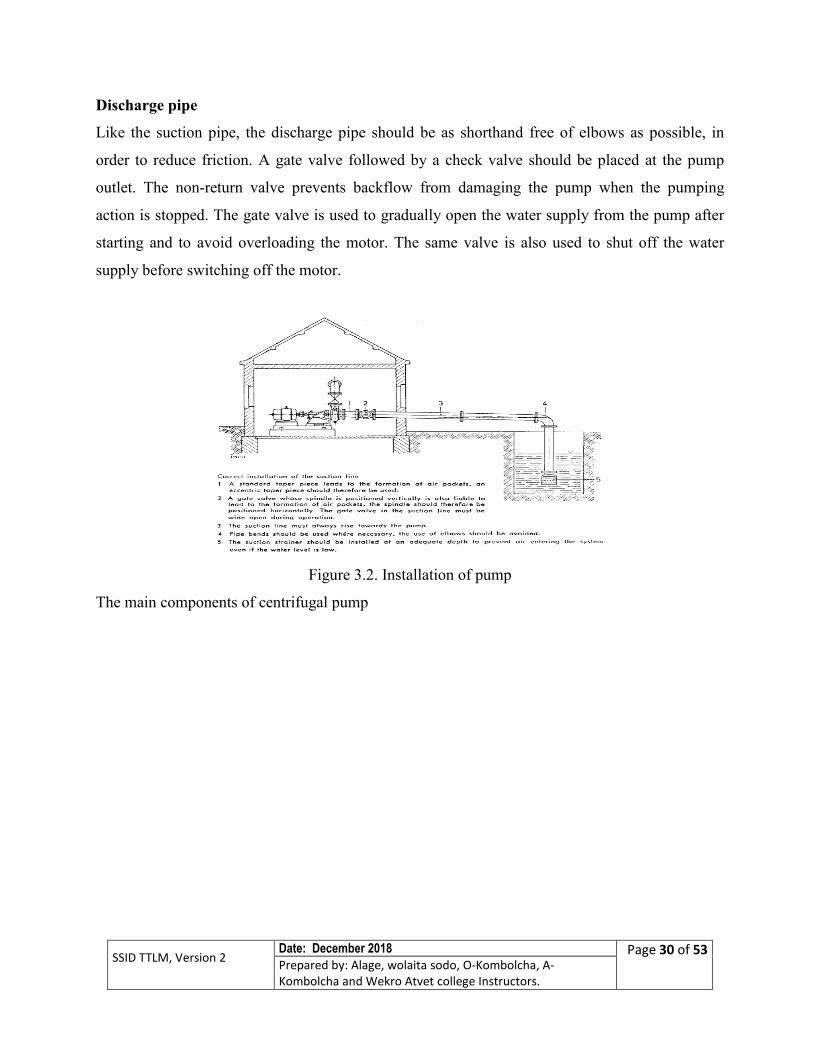
Discharge pipe
Like the suction pipe, the discharge pipe should be as shorthand free of elbows as possible, in
order to reduce friction. A gate valve followed by a check valve should be placed at the pump
outlet. The non-return valve prevents backflow from damaging the pump when the pumping
action is stopped. The gate valve is used to gradually open the water supply from the pump after
starting and to avoid overloading the motor. The same valve is also used to shut off the water
supply before switching off the motor.
Figure 3.2. Installation of pump
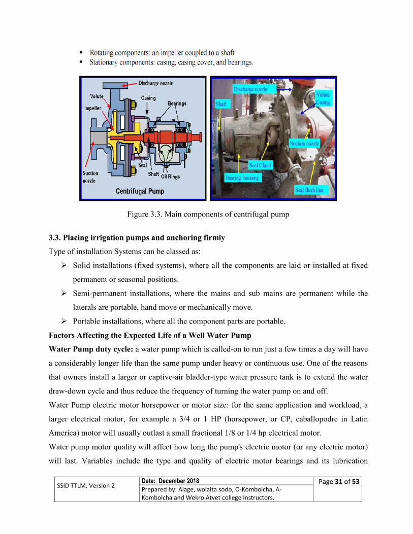
The main components of centrifugal pump
SSID TTLM, Version 2
Date: December 2018 Page 31 of 53 Prepared by: Alage, wolaita sodo, O-Kombolcha, A-
Kombolcha and Wekro Atvet college Instructors.
Figure 3.3. Main components of centrifugal pump
3.3. Placing irrigation pumps and anchoring firmly
Type of installation Systems can be classed as:
Solid installations (fixed systems), where all the components are laid or installed at fixed
permanent or seasonal positions.
Semi-permanent installations, where the mains and sub mains are permanent while the
laterals are portable, hand move or mechanically move.
Portable installations, where all the component parts are portable.
Factors Affecting the Expected Life of a Well Water Pump
Water Pump duty cycle: a water pump which is called-on to run just a few times a day will have
a considerably longer life than the same pump under heavy or continuous use. One of the reasons
that owners install a larger or captive-air bladder-type water pressure tank is to extend the water
draw-down cycle and thus reduce the frequency of turning the water pump on and off.
Water Pump electric motor horsepower or motor size: for the same application and workload, a
larger electrical motor, for example a 3/4 or 1 HP (horsepower, or CP, caballopodre in Latin
America) motor will usually outlast a small fractional 1/8 or 1/4 hp electrical motor.
Water pump motor quality will affect how long the pump's electric motor (or any electric motor)
will last. Variables include the type and quality of electric motor bearings and its lubrication
SSID TTLM, Version 2
Date: December 2018 Page 32 of 53 Prepared by: Alage, wolaita sodo, O-Kombolcha, A-
Kombolcha and Wekro Atvet college Instructors.
requirements. Where an electric motor is manufactured, even when it claims to be the same brand,
can make a significant difference. For example according to our Mexican consultants, electric
pump motors made in Mexico sometimes perform less durably than a similar motor manufactured
to U.S. standards.
Water sediment is a major wear factor on the pump assembly itself (as opposed to the electric
motor that drives the pump). Sediment in water acts as an abrasive that wears pump bearings and
other moving parts.
Quality of Water Equipment Installation: can make a big difference in the life of the water
supply equipment. Installers who simply hook up a pump and wiring, with no understanding of
the importance of proper location of check valves, filters, proper electrical wiring, etc. are likely
to be providing a shorter-lived water supply system.
Proper match of the well pump capacity and its output rate to the well's safe yield. See well
yield: well flow rate where we define safe well yield. Also see air discharge at faucets, fixtures.
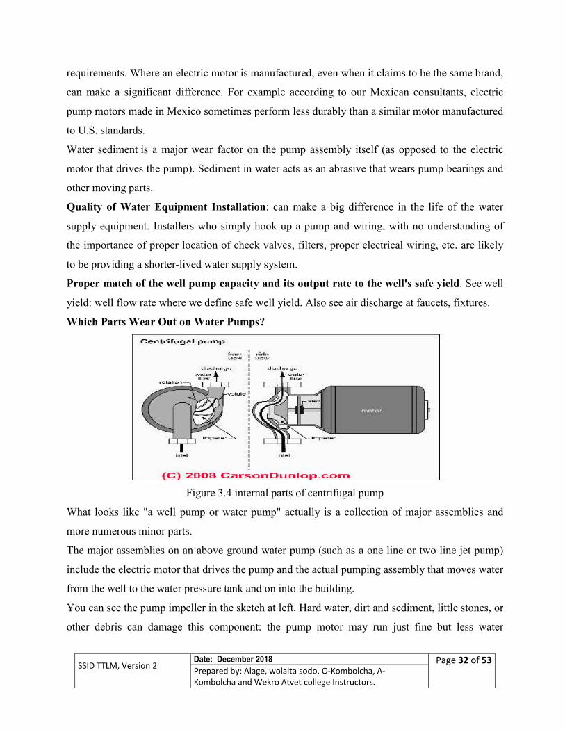
Which Parts Wear Out on Water Pumps?
Figure 3.4 internal parts of centrifugal pump
What looks like "a well pump or water pump" actually is a collection of major assemblies and
more numerous minor parts.
The major assemblies on an above ground water pump (such as a one line or two line jet pump)
include the electric motor that drives the pump and the actual pumping assembly that moves water
from the well to the water pressure tank and on into the building.
You can see the pump impeller in the sketch at left. Hard water, dirt and sediment, little stones, or
other debris can damage this component: the pump motor may run just fine but less water
SSID TTLM, Version 2
Date: December 2018 Page 33 of 53 Prepared by: Alage, wolaita sodo, O-Kombolcha, A-
Kombolcha and Wekro Atvet college Instructors.
pressure or flow may be delivered by the pump.
A submersible pump includes these two major assemblies (electric pump motor and water pump
assembly) and adds an internal check valve.
Sketch courtesy of Carson Dunlop.
Pump bearings
Pump impeller or rotary vanes that move water - see sketch above
Pump motor bearings inside the electric motor that drives the water pump
Internal pump check valves
Pump control switches
Which are normally physically separate devices, also wear or fail, becoming clogged with
sediment or suffering burned electrical contacts. See well pump pressure control adjustment for
details. Other well piping components that are not part of the well pump itself, but that affect
pump life, such as well piping check valves, well piping foot valves, or a well piping tail
piece may also need to be installed, repaired, or replaced.
How can we maximize the life expectancy of a water pump?
Install a sediment filter ahead of the water pump in above ground water pump
installations. Most well equipment installers place a filter after the water pump, or even
after the water pressure tank rather than ahead of these components. If the well water has a
high sediment level placing a sediment filter upstream or before the water passes through
the water pump will extend the pump life significantly.
Install check valves where they will protect the water pump from loss of prime and
having to work as hard to restore prime. For example, while most submersible pumps
contain their own integrated check valve, installing a second check valve at the top of the
well or further in the well piping reduces the load on the water pump's internal valve,
protects against loss of prime in the well piping, and extends the life of the water pump
itself.
Select a pump motor horsepower or size which is appropriate for the anticipated usage
or duty cycle for the well and pump installation. In general a larger motor will outlast a
smaller pump motor. Match the pump output rate to the safe well yield. See Well Yield:
Well Flow Rate. This avoids water pump cavitation that can damage the pump.
SSID TTLM, Version 2
Date: December 2018 Page 34 of 53 Prepared by: Alage, wolaita sodo, O-Kombolcha, A-
Kombolcha and Wekro Atvet college Instructors.
Use a well drawdown low water cutoff device or well tailpipe: Install a well piping tail
piece (or well low water cutoff) or a well drawdown pump protection tailpiece in the well
itself if the pump is likely to encounter seasonal low water table conditions that drop the
well safe yield point, install a drawdown cutoff device or low-water cutoff device (also
called drawdown protection device) in the well to protect the pump.
Wire the pump for 240V: If your pump motor and control are labeled indicating that it is
permitted to run the pump at either 120V or 240V, and if you are installing the pump new,
there are some advantages to wiring the pump to operate on 240V rather than 120V. The
motor will start more easily and you might improve the pump motor life.
Most well pumps, except the very smallest models, can be wired to run at either voltage
level. The higher voltage will make it easier for the pump to start. The efficiency of the
water pump and its operating cost will be about the same regardless of the voltage used.
See Efficiency of 120V vs. 240V Equipment for an answer to the question of whether or
not changing a well pump from 120V to 240V will save in operating cost. (Basically, no.)
Also see definitions of electrical terms for definitions of amps, volts, watts, ohms, etc.
Perform necessary pump maintenance: some water pumps require inspection and
replacement of internal parts such as bearings or impellers as often as after just four or
five years of use. While it may be possible to ignore this maintenance for a while, the
effect may be to so wear the pump or pump motor parts that complete pump or pump
motor replacement are necessary.
Check available voltages on the pump motor circuit. We speculate that some electric
motors will fail sooner if they are required to frequently operate at voltages lower than
their design voltage range.
Maintain the water pressure tank: a water pressure tank which has lost its air charge
and is short cycling is very hard on and shortens the life of a water pump. See short
cycling water pumps
Install a Smart Tank or other water pressure regulation device that regulates water flow in
the building to reduce the water pump cycling rate
See water pumps & tanks for a discussion of common failures and repairs on water
pumps and water tanks. Start more easily and you might improve the pump motor life.
SSID TTLM, Version 2
Date: December 2018 Page 35 of 53 Prepared by: Alage, wolaita sodo, O-Kombolcha, A-
Kombolcha and Wekro Atvet college Instructors.
Most well pumps, except the very smallest models, can be wired to run at either voltage level.
The higher voltage will make it easier for the pump to start. The efficiency of the water pump and
its operating cost will be about the same regardless of the voltage used. See efficiency of 120v vs.
240v equipment for an answer to the question of whether or not changing a well pump from 120v
to 240v will save in operating cost. (Basically no.) Also see definitions of electrical terms for
definitions of Amps, Volts, Watts, Ohms, etc.
Perform necessary pump maintenance: some water pumps require inspection and replacement
of internal parts such as bearings or impellers as often as after just four or five years of use. While
it may be possible to ignore this maintenance for a while, the effect may be to so wear the pump
or pump motor parts that complete pump or pump motor replacement are necessary.
Check available voltages on the pump motor circuit. We speculate that some electric motors will
fail sooner if they are required to frequently operate at voltages lower than their design voltage
range.
Maintain the water pressure tank: a water pressure tank which has lost its air charge and is
short cycling is very hard on and shortens the life of a water pump. See short cycling water pumps
Install a smart tank or other water pressure regulation device that regulates water flow in the
building to reduce the water pump cycling rate
See water pumps & tanks for a discussion of common failures and repairs on water pumps and
water tanks.
A kinetic water ram pump uses the force of running water in a stream combined with the
principles of hydraulics to lift water as much as 50 meters from the pump location. The water ram
was invented in 1780 by Frenchman Joseph Michael Montgolfier. Since surface or stream water is
unlikely to be sanitary in most locations, water ram pumps are used mostly in agriculture to move
stream water to fields for irrigation.
A very different water ram, a "kinetic water ram" pump using compressed air to clear clogged
building drains is available and is discussed at clogged drain diagnosis & repair. That kinetic
water ram is a drain clearing tool not a water pump. Photo & Description of Hand Pumps and
Windmills or Mechanical Pumps for Pumping Water
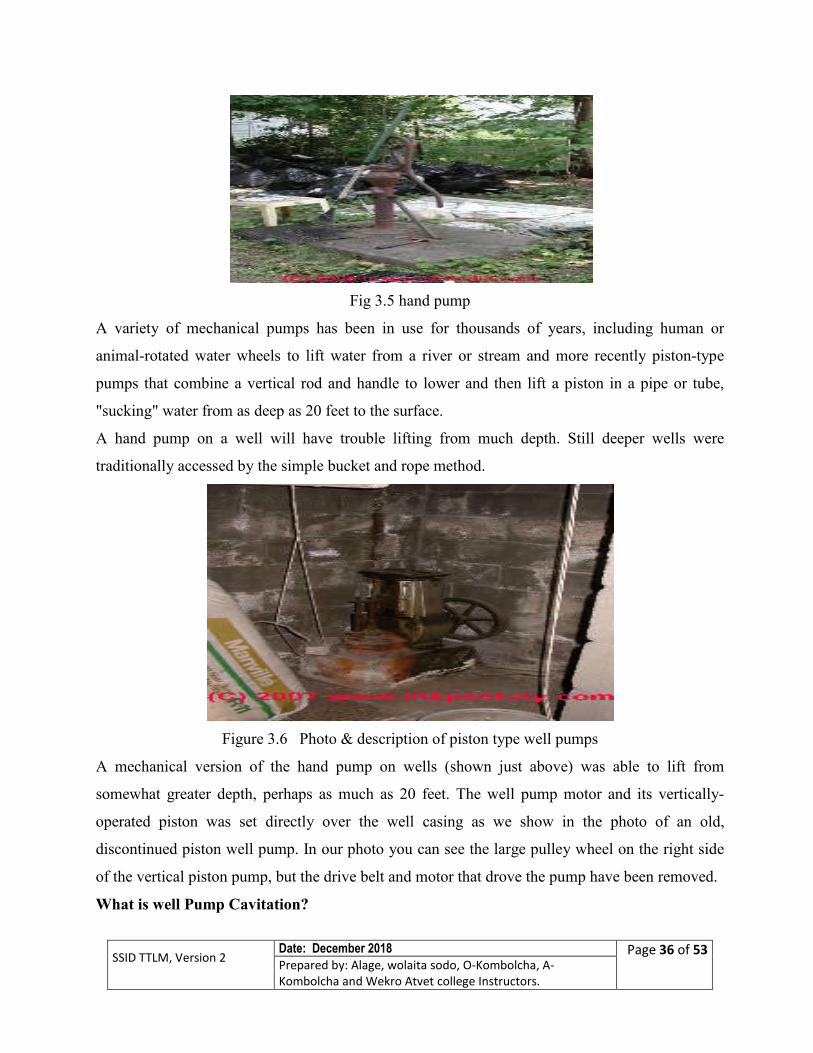
SSID TTLM, Version 2
Date: December 2018 Page 36 of 53 Prepared by: Alage, wolaita sodo, O-Kombolcha, A-
Kombolcha and Wekro Atvet college Instructors.
Fig 3.5 hand pump
A variety of mechanical pumps has been in use for thousands of years, including human or
animal-rotated water wheels to lift water from a river or stream and more recently piston-type
pumps that combine a vertical rod and handle to lower and then lift a piston in a pipe or tube,
"sucking" water from as deep as 20 feet to the surface.
A hand pump on a well will have trouble lifting from much depth. Still deeper wells were
traditionally accessed by the simple bucket and rope method.
Figure 3.6 Photo & description of piston type well pumps
A mechanical version of the hand pump on wells (shown just above) was able to lift from
somewhat greater depth, perhaps as much as 20 feet. The well pump motor and its vertically-
operated piston was set directly over the well casing as we show in the photo of an old,
discontinued piston well pump. In our photo you can see the large pulley wheel on the right side
of the vertical piston pump, but the drive belt and motor that drove the pump have been removed.
What is well Pump Cavitation?
SSID TTLM, Version 2
Date: December 2018 Page 37 of 53 Prepared by: Alage, wolaita sodo, O-Kombolcha, A-
Kombolcha and Wekro Atvet college Instructors.
Well pump cavitations describes the entry of air or gases into the mechanical parts that are trying
to move water through a water pump. The presence of air or other gases in the actual pump
chambers or around the water pump impellers leads to overheating of these parts and mechanical
damage to the pump moving parts. Cavitations can also cause the pump to have to work longer to
satisfy the water demand and thus its electric motor to overheat, also reducing motor life.
Cavitations inside of a water pump can be caused by several problems including:
Inadequate well yield: if the yield of a well drops for any reason, trying to pump water beyond
the safe yield of a well pump can introduce air into the well pump and water piping.
See Well Yield: Well Flow Rate where we define safe well yield. Also see air discharge at
faucets, fixtures.
Oversized pumps that mis-match the well flow rate to the pump's output rate can also cause the
pump to form a strong vacuum inside the pumping chamber around the pump impeller. The
vacuum, in turn, causes dissolved gases in the water itself to leave solution and return to bubble
form. Low water cutoff devices and well tailpieces for well pump protection on a low-flow-rate
well. For details about well pipe tailpieces, tail pipes, or other low water cutoff devices that
protect the well pump from damage when the well flow is too limited, please see our compete
article at well piping tail piece.
Self-Check -3 Written Test
Name: _________________________ Date: _______________
Directions: Answer all the questions listed below.
1. What is the purpose of using pump? Explain briefly (5pts.)
2. What factors we are expected to consider during setting up of pumping station? (5pts.)
3. List the pump installation procedures clearly and explain it briefly (8pts.)
4. How can we maximize the life expectancy of a water pump? Explain (6 pts)
Note: Satisfactory rating - 12 points and above Unsatisfactory - below 12 points
You can ask your teacher for the copy of the correct answers
SSID TTLM, Version 2
Date: December 2018 Page 38 of 53 Prepared by: Alage, wolaita sodo, O-Kombolcha, A-
Kombolcha and Wekro Atvet college Instructors.
Operation sheet-3 Install small motorized and manual irrigation pumps
Objective: Installation of small motorized and manual irrigation pumps
Purpose: - Pumps are designed to move fluid, pumps transfer fluid for processing, and in most
plants pumps are a critical part of daily operation
Equipment, Tools and Materials:
Treadle pump, rope and washer, suction hose and delivery hose, pumps, foot valve.
Conditions: Oversized pumps that miss-match the well flow rate to the pump's output rate can
also cause the pump to form a strong vacuum inside the pumping chamber around the pump
impeller. The vacuum, in turn, causes dissolved gases in the water itself to leave solution and
return to bubble form
Procedure:
Prepare installation plan
Use appropriate PPE’s
Select appropriate site for installation
Placing lifting device on well leveled bed and anchored firmly
Install a sediment filter ahead of the water pump
Install check valves
Select a pump motor horsepower or size
Use a well drawdown low water cutoff device or well tailpipe
Fixing parts together or Installed at fixed permanent or seasonal positions.
Check the functionality of each installed components and finish the task
Precaution:
Before installation sure that you use appropriate PPE’s. .
Quality Criteria:
Most well pumps, except the very smallest models, can be wired to run at either voltage level.
The higher voltage will make it easier for the pump to start. The efficiency of the water pump and
its operating cost will be about the same regardless of the voltage used.
SSID TTLM, Version 2
Date: December 2018 Page 39 of 53 Prepared by: Alage, wolaita sodo, O-Kombolcha, A-
Kombolcha and Wekro Atvet college Instructors.
LAP Test/ Job Sheet Practical Demonstration
Name: _____________________________ Date: ________________
Time started: ________________________ Time finished: ________________
Instructions:
You are required to perform the following:
Request a set of different activities in installation of small motorized and manual pump and then
perform the following task in front of your trainer:
Select appropriate site for installation
Prepare necessary components of small motorized and manual irrigation pumps
Install small motorized and manual irrigation pumps in front of your teacher
Information Sheet-4
Operate small motorized and manual irrigation pumps
4.1 characterize small motorized and manual irrigation pump
Small motor pumps: refer to diesel or kerosene fueled motor pumps that have a typical size
between 0.5 and 2.5 hp, and have been optimized to use as little fuel as possible. Proper motor
pump selection can reduce fuel consumption significantly, which can lead to significant cost
reduction. New cost-efficient irrigation pumps are available in countries such as China and India.
Chinese 4HP diesel pumps can irrigate 5 ha up to heads of 6 m, consuming 0.45 liters of fuel an
hour. Chinese petrol pumps of 1.5 HP pump 3 liters per second and consume less than 0.3 liters of
gasoline per hour.
Manually operated pumps: they use human power and mechanical advantage to move fluids or
air from one place to another. They are widely used in every country in the world for a variety of
industrial, marine, irrigation and leisure activities. There are many different types of hand pump
available, mainly operating on a piston, diaphragm or rotary vane principle with a check valve on
the entry and exit ports to the chamber operating in opposing directions. Most hand pumps are
either piston pumps or plunger pumps, and are positive displacement. Hand pumps are commonly
SSID TTLM, Version 2
Date: December 2018 Page 40 of 53 Prepared by: Alage, wolaita sodo, O-Kombolcha, A-
Kombolcha and Wekro Atvet college Instructors.
used in developing countries for both community supply and self-supply of water and can be
installed on boreholes or hand-dug wells.
Characteristics of small motorized and manual irrigation pumps
They requires fuel/oil for operation
Operation requires skilled man technicians
They requires continuous energy
Conversion of added energy to increase in kinetic energy (increase in velocity)
Conversion of increased velocity (kinetic energy) to an increase in pressure head one
practical difference between dynamic and positive displacement pumps is their ability to
operate under closed valve conditions.
Operation requires proper handling and operation
Can be installed by a technician team of two or three persons
Are durable against corrosive groundwater
Can have quickly worn parts which are not found easily purchased and replaced
They requires lubrication, oiling and continuous follow up and maintenance
4.2. Estimating and determining capacity, brake horse power, efficiency and total head
Measuring Pump Capacity
The capacity of a pump has two components, the pump discharge rate and the discharge pressure.
The discharge rate is normally measured in gallons per minute (gpm) in English units or liters per
second (lps) in metric units. Pressure is normally measured in pounds per square inch (psi) in
English units or kilo Pascals (kPa) in metric units. It is necessary to measure both discharge rate
and pressure. Under normal operating conditions in order to determine how the pumping system
will operate as a part of an irrigation system. The cost of flow rate meters varies widely.
Brake horsepower (BHP) is the measure of an engine’s horsepower before the loss in power
caused by the pump. This gives the operator an idea of what size pump or the amount of
horsepower is needed to move the required amount of water with the best efficiency.
Calculating Horsepower
Horsepower is a measurement of the amount of energy necessary to do work. In determining the
horsepower used to pump water, we must know the:
1. Pumping rate in gallons per minute (gpm), and
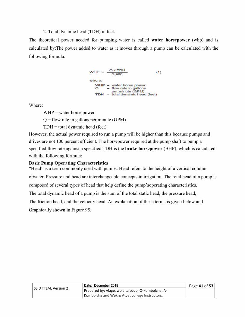
SSID TTLM, Version 2
Date: December 2018
Prepared by: Alage, wolaita sodo, OKombolcha and Wekro Atvet college Instructors.
2. Total dynamic head (TDH) in feet.
The theoretical power needed for pumping water is called
calculated by:The power added to water as it moves through a pump can be calculated with the
following formula:
Where:
WHP = water horse power
Q = flow rate in gallons per minute (GPM)
TDH = total dynamic head (feet)
However, the actual power required to run a pump will be higher than this because pumps and
drives are not 100 percent efficient. The horsepower required at the pump shaft to pump a
specified flow rate against a specified TDH is
with the following formula:
Basic Pump Operating Characteristics“Head” is a term commonly used with pumps. Head refers to the height of a vertical column
ofwater. Pressure and head are interchangeable concep
composed of several types of head that help define the pump’soperating characteristics.
The total dynamic head of a pump is the sum of the total static head, the pressure head,
The friction head, and the velocity head. An explanation of these terms is given below and
Graphically shown in Figure 95.
Date: December 2018
Prepared by: Alage, wolaita sodo, O-Kombolcha, A-Kombolcha and Wekro Atvet college Instructors.
2. Total dynamic head (TDH) in feet.
eeded for pumping water is called water horsepower
The power added to water as it moves through a pump can be calculated with the
WHP = water horse power
Q = flow rate in gallons per minute (GPM)
total dynamic head (feet)
However, the actual power required to run a pump will be higher than this because pumps and
drives are not 100 percent efficient. The horsepower required at the pump shaft to pump a
specified flow rate against a specified TDH is the brake horsepower (BHP), which is calculated
Basic Pump Operating Characteristics “Head” is a term commonly used with pumps. Head refers to the height of a vertical column
ofwater. Pressure and head are interchangeable concepts in irrigation. The total head of a pump is
composed of several types of head that help define the pump’soperating characteristics.
The total dynamic head of a pump is the sum of the total static head, the pressure head,
ty head. An explanation of these terms is given below and
Page 41 of 53
water horsepower (whp) and is
The power added to water as it moves through a pump can be calculated with the
However, the actual power required to run a pump will be higher than this because pumps and
drives are not 100 percent efficient. The horsepower required at the pump shaft to pump a
(BHP), which is calculated
“Head” is a term commonly used with pumps. Head refers to the height of a vertical column
total head of a pump is
composed of several types of head that help define the pump’soperating characteristics.
The total dynamic head of a pump is the sum of the total static head, the pressure head,
ty head. An explanation of these terms is given below and
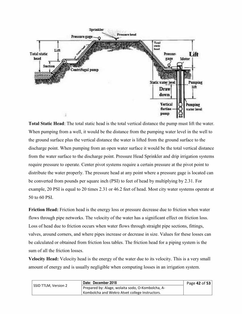
SSID TTLM, Version 2
Date: December 2018 Page 42 of 53 Prepared by: Alage, wolaita sodo, O-Kombolcha, A-
Kombolcha and Wekro Atvet college Instructors.
Total Static Head: The total static head is the total vertical distance the pump must lift the water.
When pumping from a well, it would be the distance from the pumping water level in the well to
the ground surface plus the vertical distance the water is lifted from the ground surface to the
discharge point. When pumping from an open water surface it would be the total vertical distance
from the water surface to the discharge point. Pressure Head Sprinkler and drip irrigation systems
require pressure to operate. Center pivot systems require a certain pressure at the pivot point to
distribute the water properly. The pressure head at any point where a pressure gage is located can
be converted from pounds per square inch (PSI) to feet of head by multiplying by 2.31. For
example, 20 PSI is equal to 20 times 2.31 or 46.2 feet of head. Most city water systems operate at
50 to 60 PSI.
Friction Head: Friction head is the energy loss or pressure decrease due to friction when water
flows through pipe networks. The velocity of the water has a significant effect on friction loss.
Loss of head due to friction occurs when water flows through straight pipe sections, fittings,
valves, around corners, and where pipes increase or decrease in size. Values for these losses can
be calculated or obtained from friction loss tables. The friction head for a piping system is the
sum of all the friction losses.
Velocity Head: Velocity head is the energy of the water due to its velocity. This is a very small
amount of energy and is usually negligible when computing losses in an irrigation system.
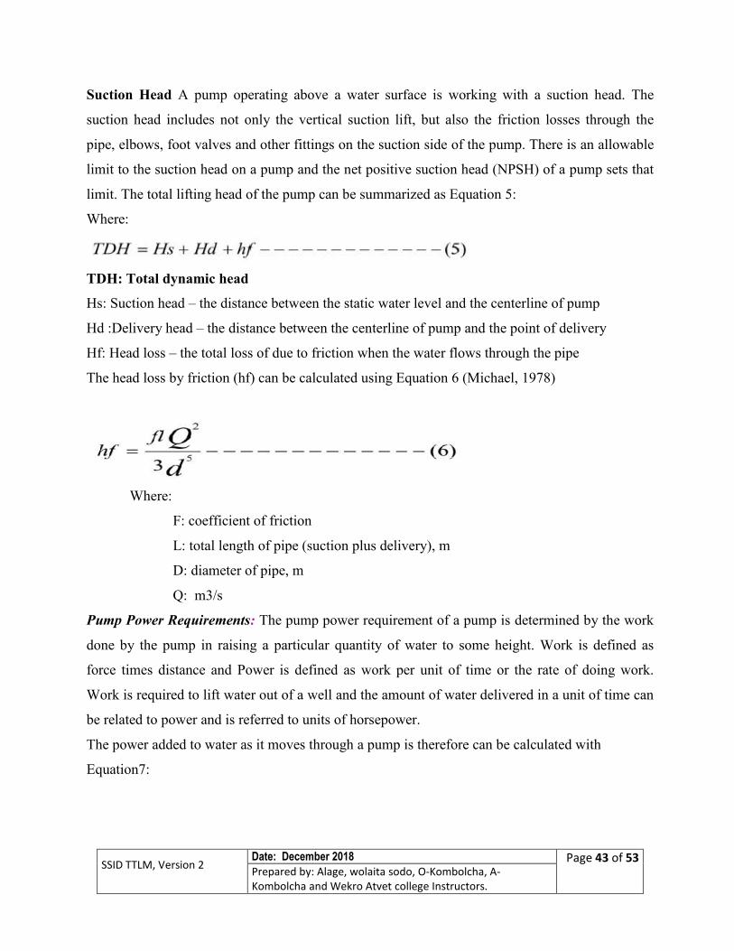
SSID TTLM, Version 2
Date: December 2018 Page 43 of 53 Prepared by: Alage, wolaita sodo, O-Kombolcha, A-
Kombolcha and Wekro Atvet college Instructors.
Suction Head A pump operating above a water surface is working with a suction head. The
suction head includes not only the vertical suction lift, but also the friction losses through the
pipe, elbows, foot valves and other fittings on the suction side of the pump. There is an allowable
limit to the suction head on a pump and the net positive suction head (NPSH) of a pump sets that
limit. The total lifting head of the pump can be summarized as Equation 5:
Where:
TDH: Total dynamic head
Hs: Suction head – the distance between the static water level and the centerline of pump
Hd :Delivery head – the distance between the centerline of pump and the point of delivery
Hf: Head loss – the total loss of due to friction when the water flows through the pipe
The head loss by friction (hf) can be calculated using Equation 6 (Michael, 1978)
Where:
F: coefficient of friction
L: total length of pipe (suction plus delivery), m
D: diameter of pipe, m
Q: m3/s
Pump Power Requirements: The pump power requirement of a pump is determined by the work
done by the pump in raising a particular quantity of water to some height. Work is defined as
force times distance and Power is defined as work per unit of time or the rate of doing work.
Work is required to lift water out of a well and the amount of water delivered in a unit of time can
be related to power and is referred to units of horsepower.
The power added to water as it moves through a pump is therefore can be calculated with
Equation7:
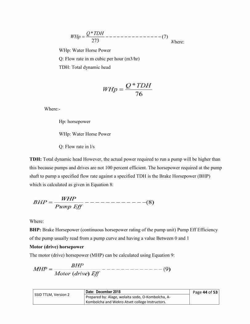
SSID TTLM, Version 2
Date: December 2018 Page 44 of 53 Prepared by: Alage, wolaita sodo, O-Kombolcha, A-
Kombolcha and Wekro Atvet college Instructors.
Where:
WHp: Water Horse Power
Q: Flow rate in m cubic per hour (m3/hr)
TDH: Total dynamic head
Where:-
Hp: horsepower
WHp: Water Horse Power
Q: Flow rate in l/s
TDH: Total dynamic head However, the actual power required to run a pump will be higher than
this because pumps and drives are not 100 percent efficient. The horsepower required at the pump
shaft to pump a specified flow rate against a specified TDH is the Brake Horsepower (BHP)
which is calculated as given in Equation 8:
Where:
BHP: Brake Horsepower (continuous horsepower rating of the pump unit) Pump Eff Efficiency
of the pump usually read from a pump curve and having a value Between 0 and 1
Motor (drive) horsepower
The motor (drive) horsepower (MHP) can be calculated using Equation 9:
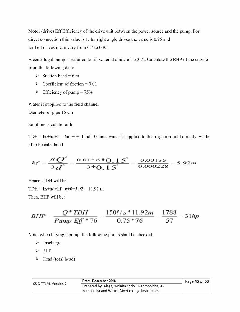
SSID TTLM, Version 2
Date: December 2018 Page 45 of 53 Prepared by: Alage, wolaita sodo, O-Kombolcha, A-
Kombolcha and Wekro Atvet college Instructors.
Motor (drive) Eff Efficiency of the drive unit between the power source and the pump. For
direct connection this value is 1, for right angle drives the value is 0.95 and
for belt drives it can vary from 0.7 to 0.85.ple 5 Example 5v
A centrifugal pump is required to lift water at a rate of 150 l/s. Calculate the BHP of the engine
from the following data:
Suction head = 6 m
Coefficient of friction = 0.01
Efficiency of pump = 75%
Water is supplied to the field channel
Diameter of pipe 15 cm
SolutionCalculate for h;
TDH = hs+hd+h = 6m +0+hf, hd= 0 since water is supplied to the irrigation field directly, while
hf to be calculated
Hence, TDH will be:
TDH = hs+hd+hf= 6+0+5.92 = 11.92 m
Then, BHP will be:
Note, when buying a pump, the following points shall be checked:
Discharge
BHP
Head (total head)
SSID TTLM, Version 2
Date: December 2018 Page 46 of 53 Prepared by: Alage, wolaita sodo, O-Kombolcha, A-
Kombolcha and Wekro Atvet college Instructors.
Efficiency of pump
Centrifugal pump efficiency is the ratio of Hydraulic power delivered by the pump to the brake
horsepower supplied to the pump.
Hydraulic Power (Power Output from Pump):
Centrifugal Pump consumes energy to develop the discharge pressure and to deliver flow. Therefore Hydraulic Horsepower of the Pump depends on these two parameters.
Power Output from Pump = (P2 – P1) * Q
P2: Pump Discharge pressure in N/m2
P1: Pump suction pressure in N/m2
Q: Flow delivered by pump in m3/s
Brake Horse Power (Power Input to Pump):
This is the power given to the pump through Electric Motor. Power output from the electric driver is calculated by the formula
Power Input to Pump = 1.732 * V * I * PF * Motor Efficiency * Coupling Efficiency
V: Measured Voltage of Motor in Volt
I: Measured Current of Motor in Ampere
PF: Power Factor Centrifugal pump efficiency equation
Centrifugal pump efficiency = Power Output from Pump/ Power Input to Pump * 100
1. An irrigator desires to lift an irrigation water of 30 l/s a vertical height of 12 m. If the loss
of head in the casing and pump results in a 62% overall pump efficiency and the electric
motor has an efficiency of 91%, how many horsepower will his motor need? How many kw
will it use while pumping? Assume
1hp=0.746 KW
Solution:
Given data:
Q= 30 l/s
h= 12 m
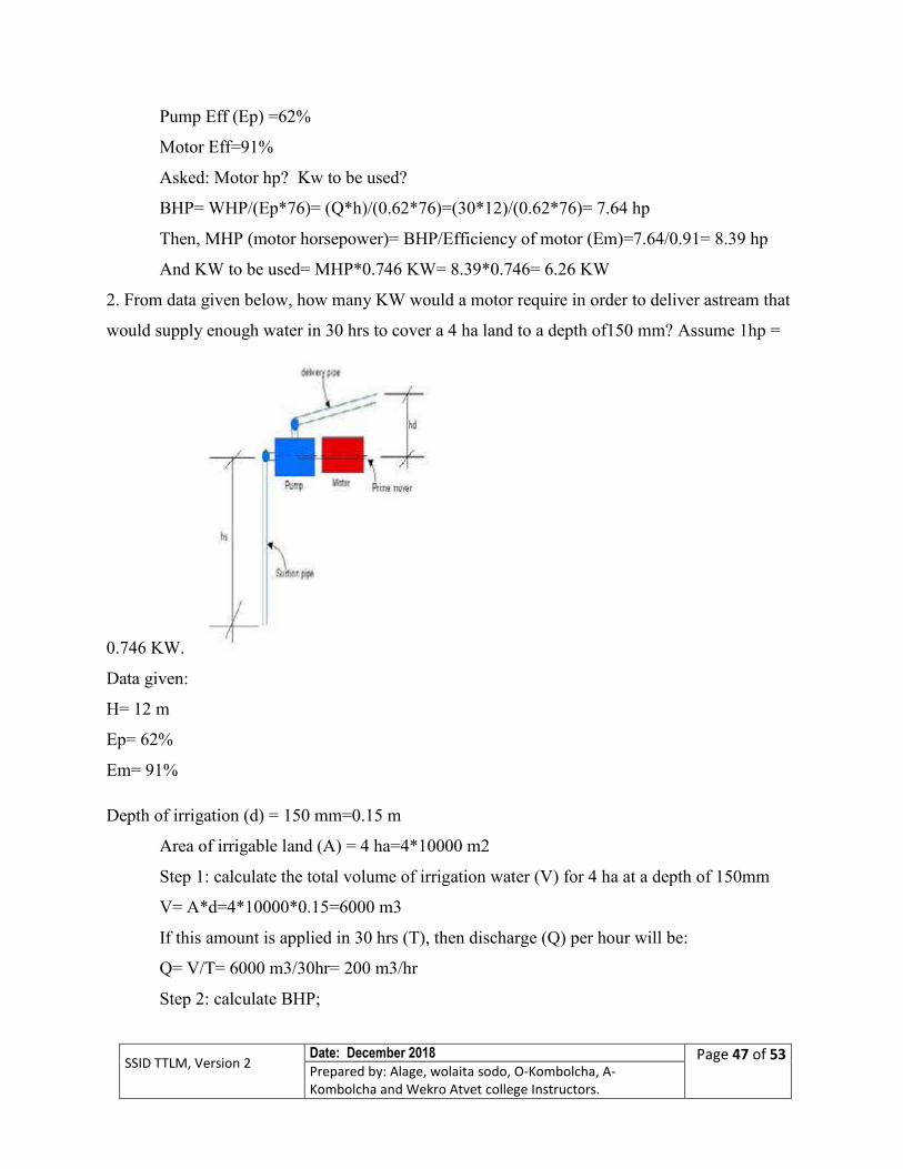
SSID TTLM, Version 2
Date: December 2018 Page 47 of 53 Prepared by: Alage, wolaita sodo, O-Kombolcha, A-
Kombolcha and Wekro Atvet college Instructors.
Pump Eff (Ep) =62%
Motor Eff=91%
Asked: Motor hp? Kw to be used?
BHP= WHP/(Ep*76)= (Q*h)/(0.62*76)=(30*12)/(0.62*76)= 7.64 hp
Then, MHP (motor horsepower)= BHP/Efficiency of motor (Em)=7.64/0.91= 8.39 hp
And KW to be used= MHP*0.746 KW= 8.39*0.746= 6.26 KW
2. From data given below, how many KW would a motor require in order to deliver astream that
would supply enough water in 30 hrs to cover a 4 ha land to a depth of150 mm? Assume 1hp =
0.746 KW.
Data given:7
H= 12 m
Ep= 62%
Em= 91%
Depth of irrigation (d) = 150 mm=0.15 m
Area of irrigable land (A) = 4 ha=4*10000 m2
Step 1: calculate the total volume of irrigation water (V) for 4 ha at a depth of 150mm
V= A*d=4*10000*0.15=6000 m3
If this amount is applied in 30 hrs (T), then discharge (Q) per hour will be:
Q= V/T= 6000 m3/30hr= 200 m3/hr
Step 2: calculate BHP;
SSID TTLM, Version 2
Date: December 2018 Page 48 of 53 Prepared by: Alage, wolaita sodo, O-Kombolcha, A-
Kombolcha and Wekro Atvet college Instructors.
BHP= WHP/(Ep*273)= (Q*h) / (0.62*273)= (200*12) / (0.62*273)= 14.18 hp
Step 3: Calculate for motor horsepower, MHP;
MHP= BHP/ME= 14.18/0.91= 15.58~16 hp
Step 4: Calculate for motor power required in KW,
Mp= MHP*0.746= 11.62 KW
4.2 Maintaining pump
I. small motorized water pumps maintenance
Maintenance Tasks
Remove tape on all engine openings and the distributor cap, and tighten belts.
Charge batteries and connect them.
Open fuel tank shutoff valve.
Before starting the engine, override safety switches that protect against low water
pressure, loss of oil pressure, and overheating. After engine has reached operating speed,
activate the safety switches.
Run the engine for 10 minutes, then turn it off and check oil and coolant levels.
Check engine and pump for any leaks caused by drying gaskets.
Engine Air System
Always replace disposable air filters with new ones. Cleaning can distort the filters and
allow more dirt to enter.
Maintenance Tasks (at season start up)
At season startup, clean and refill the filter bath in oil-bath air cleaners and reassemble the
air cleaner.
Periodically brush blockage off the screen if the air induction system is equipped with a
pre-screener.
Change the air filter when the service indicator signals that it’s time to change it:
Turn off engine before changing cone (NOT oil) air filter.
Wipe the outside of the cover and housing with a damp cloth and remove the cover.
If cover is dented or warped, replace it.
SSID TTLM, Version 2
Date: December 2018 Page 49 of 53 Prepared by: Alage, wolaita sodo, O-Kombolcha, A-
Kombolcha and Wekro Atvet college Instructors.
Use extreme care when removing the filter to prevent dirt from falling into the intake duct.
Use a clean damp cloth to wipe inside of filter housing.
Install new air filter.
At season startup
Inspect breaker points for wear and replace if needed.
Set the gap or dwell angle and lubricate the rotor.
Check timing and adjust if necessary.
Clean all connecting terminals; cover with protectors.
Spray silicone on electrically operated safety switches and ignition system to prevent
corrosion.
Engine Shutdown (End of Season)
Drain all fuel from the tank and lines and shut off the fuel valve.
Remove spark plugs. Pour a table-spoon of clean motor oil into each spark plug hole.
Position spark plug wire away from cylinder opening and rotate crankshaft by hand to
lubricate piston and rings. Replace spark plug.
Seal the distributor cap with duct tape where the cap joins the distributor housing.
Seal all the openings in the engine with duct tape, including air cleaner inlet, exhaust
outlet, and crankcase breather tube.
If the engine coolant is water, drain and refill the cooling system with water, a rust
inhibitor, and antifreeze.
Remove tension from belts.
Remove and store batteries in a cool but not freezing location. Do not store batteries
directly on concrete.
II. Manual water pumps maintenance
The only part of the pump requiring maintenance would be the rotating rim, gears and handles.
On a monthly basis these parts should be inspected for fatigue and grease applied to help reduce
friction and make the turning of these components easier. Also keep a look out for any rust which
can be fixed by sanding and repainting.
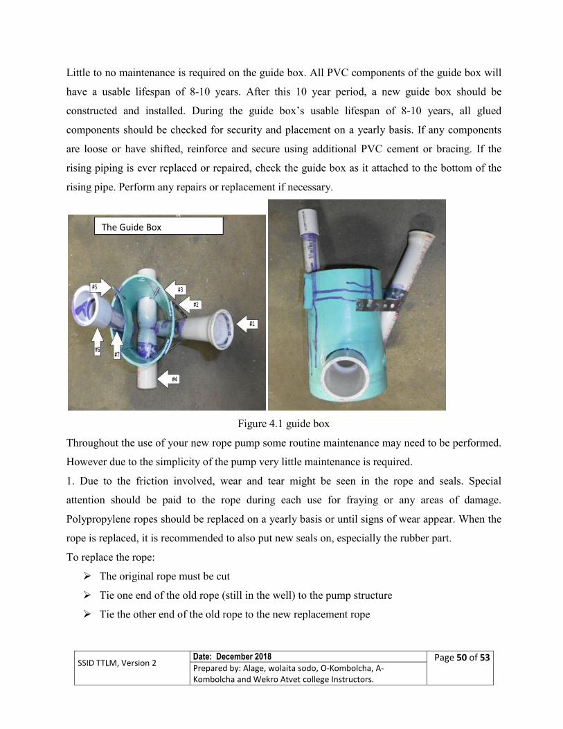
SSID TTLM, Version 2
Date: December 2018 Page 50 of 53 Prepared by: Alage, wolaita sodo, O-Kombolcha, A-
Kombolcha and Wekro Atvet college Instructors.
Little to no maintenance is required on the guide box. All PVC components of the guide box will
have a usable lifespan of 8-10 years. After this 10 year period, a new guide box should be
constructed and installed. During the guide box’s usable lifespan of 8-10 years, all glued
components should be checked for security and placement on a yearly basis. If any components
are loose or have shifted, reinforce and secure using additional PVC cement or bracing. If the
rising piping is ever replaced or repaired, check the guide box as it attached to the bottom of the
rising pipe. Perform any repairs or replacement if necessary.
Figure 4.1 guide box
Throughout the use of your new rope pump some routine maintenance may need to be performed.
However due to the simplicity of the pump very little maintenance is required.
1. Due to the friction involved, wear and tear might be seen in the rope and seals. Special
attention should be paid to the rope during each use for fraying or any areas of damage.
Polypropylene ropes should be replaced on a yearly basis or until signs of wear appear. When the
rope is replaced, it is recommended to also put new seals on, especially the rubber part.
To replace the rope:
The original rope must be cut
Tie one end of the old rope (still in the well) to the pump structure
Tie the other end of the old rope to the new replacement rope
The Guide Box
SSID TTLM, Version 2
Date: December 2018 Page 51 of 53 Prepared by: Alage, wolaita sodo, O-Kombolcha, A-
Kombolcha and Wekro Atvet college Instructors.
Tie the other end of the new rope to the pump structure as well (this is a safety measure so
the rope does not get pulled all the way through).
The new rope needs to be tied to the old one and fed around the bottom guide box by
pulling the old rope (the end tied to the pump structure) until the new rope comes out and
both ends are visible.
The new rope should then carefully be untied from the pump structure and from the old
rope.
Now the replacement rope can have its free ends tied together with enough tension to stay
on the drive wheel.
With this new rope, new seals should be applied.
Guidelines:
Only rotate the pump clockwise, never turn the pump reverse direction.
Always use the pumping lock when pumping is stopped.
Don’t let very small children operate the pump. If the handle slips out of their fingers, the
pump will turn in backwards direction and the handle could hurt the children.
Don’t operate the pump with more than one person at the time. Avoid children hanging on
the handle.
Tasks are:
o Checking the tension of the rope and adjusting when needed.
o Lubricating the bushings every 2 weeks or when the bushings are running dry.
o If the bushings start to make a shrieking noise oiling is urgently needed. Add a few drops
of NEW motor oil. (In case motor oil is not available, cooking oil can be used for
emergency) Use a clean stick to apply the oil, not with your fingers and remember:
o use always new oil, never use old (used) oil!
o no good oil = no pump!
o Replacement of the rope.
Pistons usually last about twice as long as the rope. When the rope shows a lot of damage, the
rope should be changed preferably before it breaks. Tie the new rope (with the pistons) to the
old rope (be sure pistons are running in the right direction) and pass it through the tubing. It is
not necessary to take out the tubing.
SSID TTLM, Version 2
Date: December 2018 Page 52 of 53 Prepared by: Alage, wolaita sodo, O-Kombolcha, A-
Kombolcha and Wekro Atvet college Instructors.
o Replacement of pistons
The pistons should be changed, when the user has noted a reduction output.
Before changing the pistons, check the clearance in a piece of riser main to check whether
a reduced output is due to worn-out pistons.
o Painting
To avoid corrosion, it is essential to paint parts again that start corroding.
Clean the parts with a steel brush and roughen it with sand paper.
Then apply anticorrosive primer paint, and when it’s completely dry, finish it with paint.
Allow the paint to dry in the shade, NOT in the sun.
o The bushings
If bushings are worn out, dismantle and replace them. (If properly oiled, bushes last for
10 years or more!)
o PVC tubing
If a pump is placed in direct sunlight, the ultra-violet rays will affect the PVC parts,
causing cracks. (To prolong life of PVC, paint it!)
If the well contains fine sand, the sand will wear out PVC parts as well. In case wear is
excessive, replace tubing.
SSID TTLM, Version 2
Date: December 2018 Page 53 of 53 Prepared by: Alage, wolaita sodo, O-Kombolcha, A-
Kombolcha and Wekro Atvet college Instructors.
REFERENCES
1. Garg 2005, 19th revised edition. Irrigation engineering and hydraulic structure, India
2. Garg 2oo5, revised edition. Drainage engineering, India
3. 2nd edition by A.M Michael. Irrigation principle and practice
4. 2nd editions by George’s. Technical irrigation information
5.2nd edition FAO by W.R. Walker. Irrigation and drainage management
6. 2nd editions FAO C. Brouwer. Irrigation water management