Embed Size (px)
Citation preview
1
Agricultural Unmanned Aircraft System (AUAS)Team Two-CAN
Albert Lee (TL)Jacob NiehusAdam KuesterChris CironeMichael ScottKevin Huckshold

2
Presentation Overview• Configuration Selection (KH)• Initial Sizing (KH)• Constraint Analysis (CC)• Performance (CC)• Aerodynamics (AL)• Propulsion (MS)• Stability and Control (JN)• Structures (AK)• Configuration (KH)• Cost (MS)• Conclusion (AL)

Huckshold 3
Configuration Selection• Conventional• Canard• Biplane• Tandem Wing• Blended Wing Body• Flying Wing• Joined Wing

Huckshold 4
Configuration Selection
Final Three Configurations
Conventional Canard + Tractor Canard + Pusher
Huckshold 5
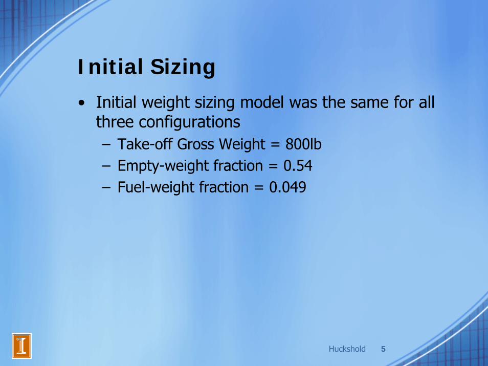
Initial Sizing• Initial weight sizing model was the same for all
three configurations– Take-off Gross Weight = 800lb– Empty-weight fraction = 0.54– Fuel-weight fraction = 0.049
Cirone 6
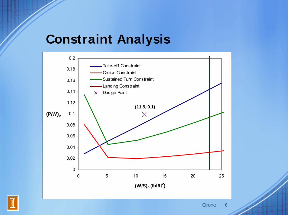
Constraint Analysis
(11.5, 0.1)
0
0.02
0.04
0.06
0.08
0.1
0.12
0.14
0.16
0.18
0.2
0 5 10 15 20 25
(W/S)o (lbf/ft2)
(P/W)o
Take-off ConstraintCruise ConstraintSustained Turn ConstraintLanding ConstraintDesign Point

Cirone 7
PerformanceChris Cirone

Cirone 8
Performance Overview
• Take Off Analysis• Cruise Analysis
– Turn Analysis• Mission Time• Fuel Consumption
•“2007 – 2008 AIAA Undergraduate Team Aircraft Design Competition,” AIAA, 2007.

Cirone 9
Take Off Analysis• RFP Constraint: 750 ft assumed total ground roll allotment.• Team Constraint: No high lift devices.• Approach: Find necessary CL,TO and corresponding VTO .
• Assumptions– Friction coefficient for grass airfield.– Ideal Thrust. (T=P*η/V, and max P for take off)– Drag form drag polar. (From Aerodynamics)– Maximum Take Off Weight. (From Configurations)
Take Off Parameters Conventional Tractor Canard Pusher Canard
Minimum CL,TO 0.934 0.977 0.978
Maximum VTO 68.8 mph 68.1 mph 68.0 mph
Factor of Stall Speed 1.24 1.21 1.21
Cirone 10
Cruise Analysis• Description:
– Spray Operation• Steady level flight at 20 ft AGL• Vop=1.3*Vstall
– Turn• Sustained turns
• Strategy: Determine most efficient spray pattern.– Race-track pattern with turns on short ends
• Minimize number of turns• Permits short half turns
Cirone 11
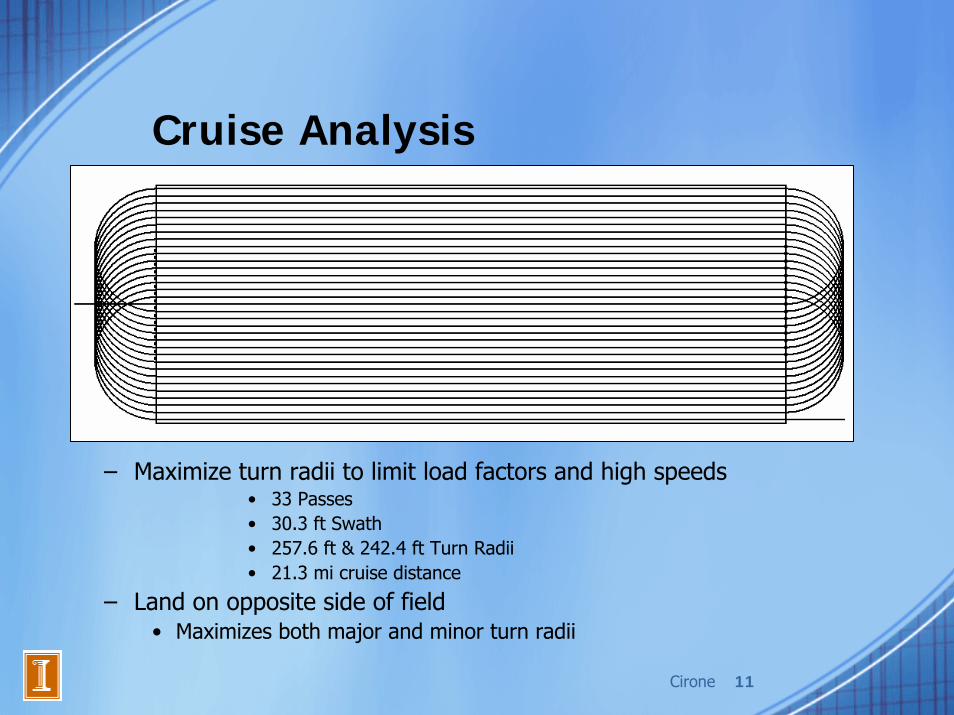
Cruise Analysis
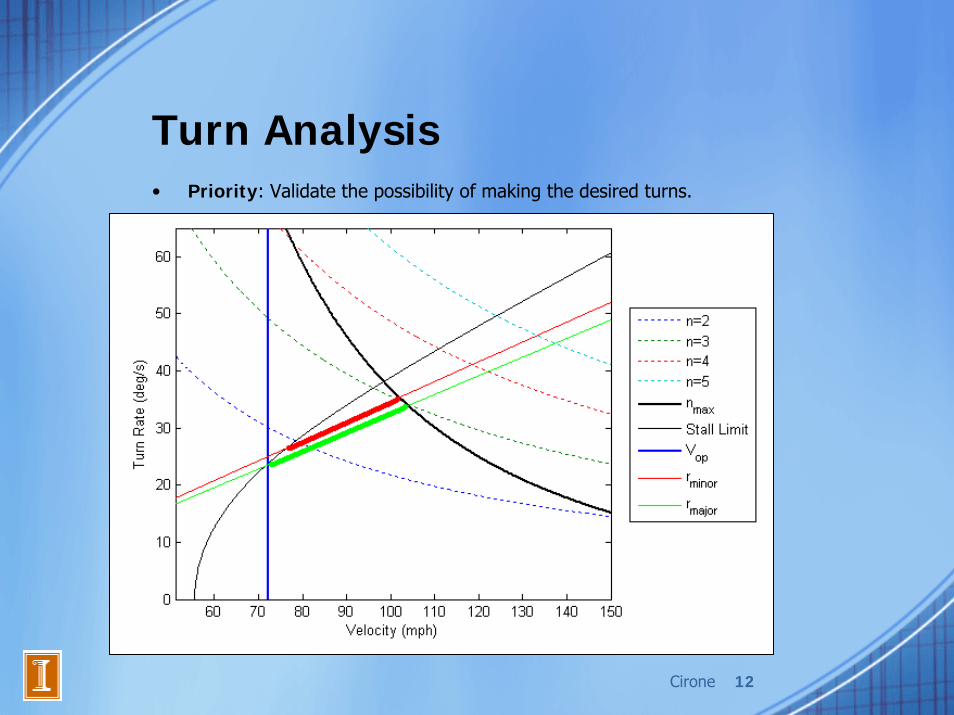
– Maximize turn radii to limit load factors and high speeds• 33 Passes• 30.3 ft Swath• 257.6 ft & 242.4 ft Turn Radii• 21.3 mi cruise distance
– Land on opposite side of field• Maximizes both major and minor turn radii
Cirone 12
Turn Analysis• Priority: Validate the possibility of making the desired turns.

Cirone 13
Mission Time & Fuel Consumption• Cruise Mission Time
– Range: 21.26 mi – Spray legs Vop= 72.2 mph– Turns CL,stall
– Constant Weight– 17.6 minutes
• Fuel Estimation– RFP requirement: 20 minutes of reserve fuel– Using a maximum specific fuel consumption – Cruise: 7.818 lbs– Reserve fuel: 8.890 lbs (Vmin,power = 60.4 mph)– 2.2 Gallons Total

Cirone 14
Future Work in Performance• Climb Analysis• Dynamic Weight Model• Enhancement of Take Off and Turn Analysis
– Include improved thrust model• Update Mission Time and Fuel Consumption
– Include all mission segments– Include improved fuel consumption model
Lee 15
AerodynamicsAlbert Lee

Lee 16
Aerodynamics Overview• Airfoil Selection• Wing Characteristics• Drag on the Plane• Coefficients for Each Mission Segment• Lift-Drag Polars
Lee 17
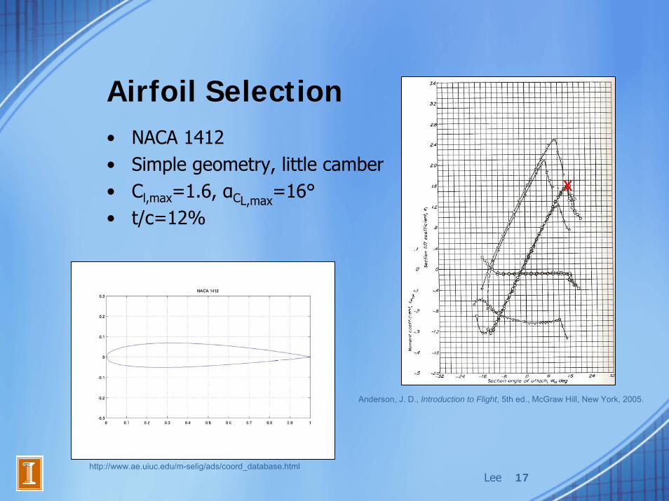
Airfoil Selection• NACA 1412• Simple geometry, little camber• Cl,max=1.6, αCL,max=16°• t/c=12%
Anderson, J. D., Introduction to Flight, 5th ed., McGraw Hill, New York, 2005.
http://www.ae.uiuc.edu/m-selig/ads/coord_database.html
x

Lee 18
Wing Characteristics• Rectangular wing• Sref=69.6ft2
• AR=6• CL,max=1.44, αCL,max=19°• Oswald span efficiency e=0.87
Lee 19
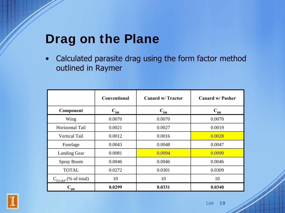
Drag on the Plane• Calculated parasite drag using the form factor method
outlined in Raymer
Conventional Canard w/ Tractor Canard w/ Pusher
Component CD0 CD0 CD0
Wing 0.0070 0.0070 0.0070
Horizontal Tail 0.0021 0.0027 0.0019
Vertical Tail 0.0012 0.0016 0.0028
Fuselage 0.0043 0.0048 0.0047
Landing Gear 0.0081 0.0094 0.0099
Spray Boom 0.0046 0.0046 0.0046
TOTAL 0.0272 0.0301 0.0309
CD,L&P (% of total) 10 10 10
CD0 0.0299 0.0331 0.0340

Lee 20
Coefficients for Each Mission Segment
CL CDo CD L/D
Takeoff 0.93 0.030 0.054 17.3
Cruise 0.85 0.030 0.074 11.5
Turn 1.44 0.030 0.156 9.2
Landing 1.23 0.030 0.123 10.0
CL CDo CD L/D
Takeoff 1.00 0.033 0.069 14.5
Cruise 0.85 0.033 0.077 11.0
Turn 1.44 0.033 0.159 9.0
Landing 1.23 0.033 0.126 9.8
CL CDo CD L/D
Takeoff 1.00 0.034 0.067 14.9
Cruise 0.85 0.034 0.081 10.4
Turn 1.44 0.034 0.170 8.5
Landing 1.23 0.034 0.134 9.2
Conventional
Canard w/ Pusher
Canard w/ Tractor

Lee 21
Lift-Drag Polars
0
0.02
0.04
0.06
0.08
0.1
0.12
0.14
0.16
0.18
-1 -0.5 0 0.5 1 1.5
CL
C D
ConventionalCanard w/ Tractor
Canard w/ Pusher
Lee 22
Future Work in Aerodynamics• Develop CFD analysis method to get more
accurate wing performance data• Look into methods of providing more lift while
minimizing drag, size and weight.
Scott 23
PropulsionMichael Scott

Scott 24
Propulsion Overview• Motor Selection• Propeller Sizing• Engine Cooling System• Fuel System• Future Work

Scott 25
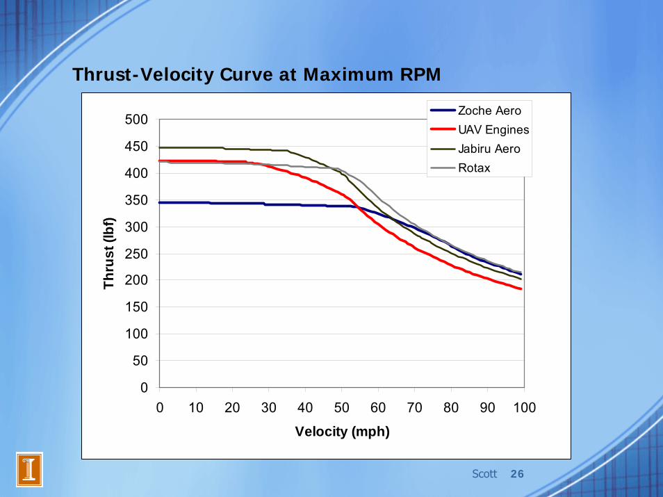
Motor Selection• 17 motors down selected to 4• Historical agricultural aircraft power loading
11 lbf/hp – 72.7 hp needed
70 250075 600081 580085 3300
Rotax (912 UL DCDL)Jabiru Aero Engine (2200A)
Zoche Aero-diesels (ZO 03A)UAV Engines Ltd (AR682)
RPMEnginePowermax
(HP)
Scott 26
0
50
100
150
200
250
300
350
400
450
500
0 10 20 30 40 50 60 70 80 90 100
Velocity (mph)
Thru
st (l
bf)
Zoche AeroUAV EnginesJabiru AeroRotax
Thrust-Velocity Curve at Maximum RPM

Scott 27
Propeller Sizing• Historical single engine aircraft disk loading
3 hp/ft2 – 8 hp/ft2
• Fixed pitch, 3 bladed propeller• Maximized blade length without tip reaching sonic velocity• Implemented gear box to reduce propeller RPM
0.80 22 0.309 3.000.65 10 0.320 2.440.63 12 0.341 2.360.70 20 0.333 2.63
Engine
Zoche Aero-diesels (ZO 03A)UAV Engines Ltd (AR682)Jabiru Aero Engine (2200A)
Rotax (912 UL DCDL) w/GB
ήp,maxPitch (deg)
Chord (ft)
T/hp (lb/hp)

Scott 28
Engine Cooling System• Down-draft vs. Up-draft• Entrance area directly related to
horsepower• Exit area set at 80% the entrance
area and expandable to 200%
Fuel System• Fuselage fuel tank - 7 gal.
- Reduce wing structure
- Ease to manufacture and maintain
• At cruise – 75% throttle- ZO 03A 2.7 gal/hr- 2200A 4.0 gal/hr- 912 UL 6.3 gal/hr- AR682 6.7 gal/hr0.32
0.340.390.37
A (ft2)Engine
Zoche Aero-diesels (ZO 03A)UAV Engines Ltd (AR682)Jabiru Aero Engine (2200A)
Rotax (912 UL DCDL) w/GB
Scott 29
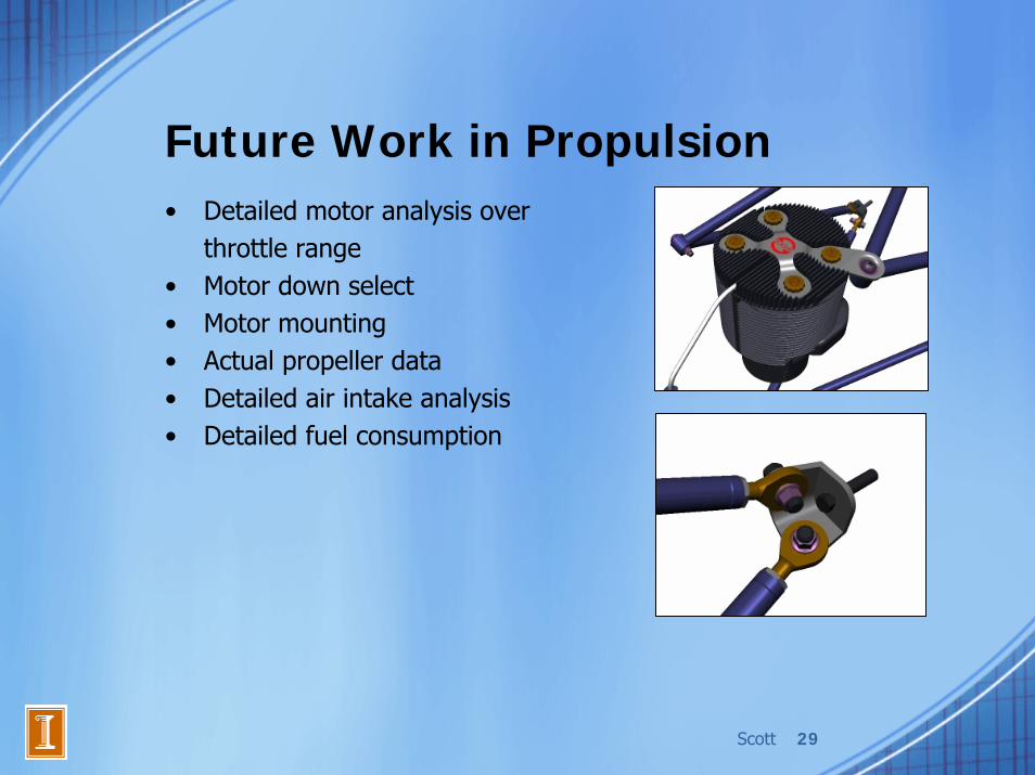
Future Work in Propulsion• Detailed motor analysis over
throttle range• Motor down select• Motor mounting• Actual propeller data• Detailed air intake analysis• Detailed fuel consumption
Niehus 30
Stability and ControlJacob Niehus
Niehus 31
Stability and Control Overview
• Determine tail and control surface geometry for adequate controllability
• Determine center of gravity location for longitudinal static stability
• RFP requirement: “ease of operation”
Niehus 32
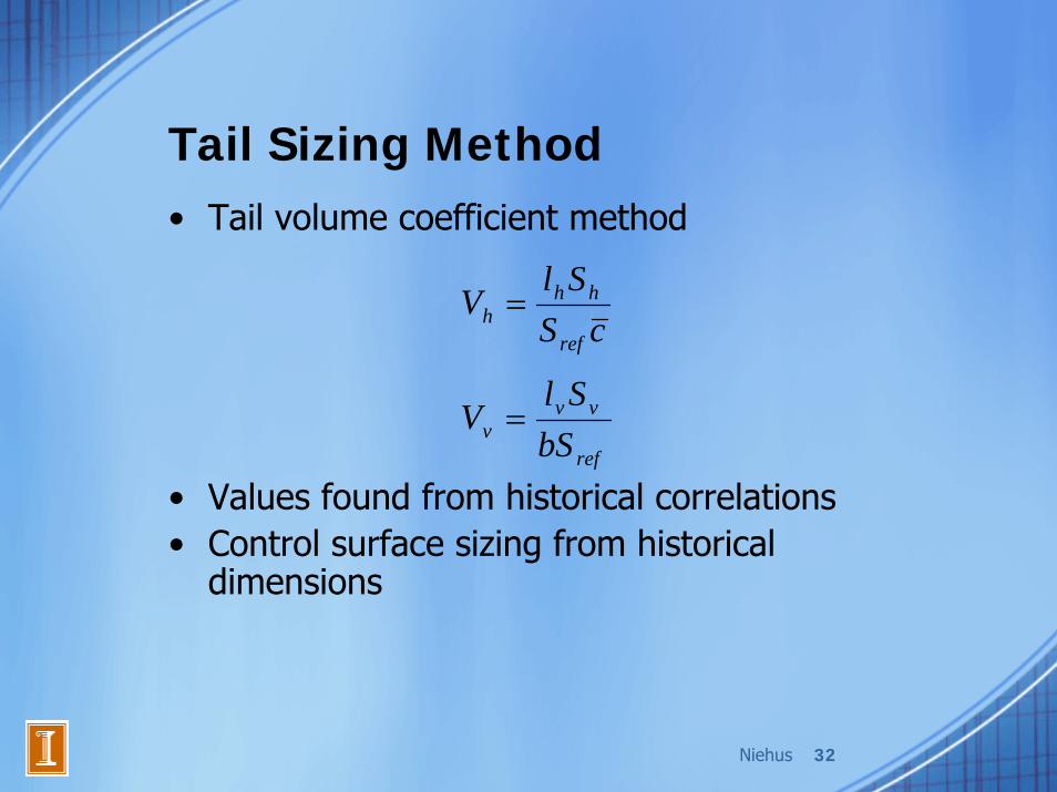
Tail Sizing Method• Tail volume coefficient method
• Values found from historical correlations• Control surface sizing from historical
dimensions
cSSl
Vref
hhh =
ref
vvv bS
SlV =

Niehus 33
Tail Sizing Trade Study
0.00
5.00
10.00
15.00
20.00
25.00
30.00
5 7 9 11 13 15
Distance between center of gravity and horizontal stabilizer (ft)
Plan
form
are
a of
hor
izon
tal s
tabi
lizer
(ft^
2)

Niehus 34
Tail Sizing Results
Niehus 35
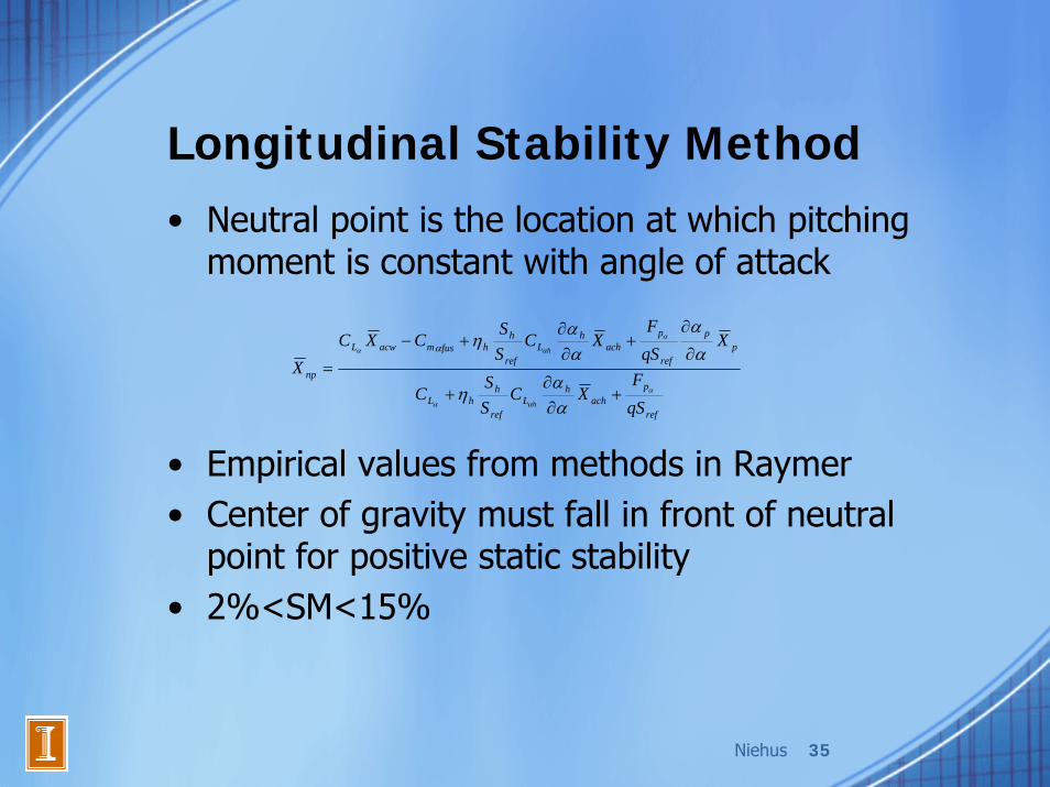
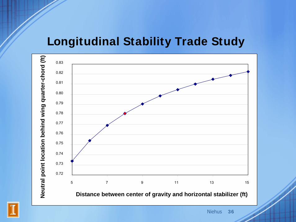
Longitudinal Stability Method• Neutral point is the location at which pitching
moment is constant with angle of attack
• Empirical values from methods in Raymer• Center of gravity must fall in front of neutral
point for positive static stability• 2%<SM<15%
ref
pach
hL
ref
hhL
pp
ref
pach
hL
ref
hhfusmacwL
np
qSF
XCSS
C
XqSF
XCSS
CXCX
h
h
α
αα
α
αα
αα
η
αα
αα
ηα
+∂∂
+
∂
∂+
∂∂
+−
=
Niehus 36
Longitudinal Stability Trade Study
0.72
0.73
0.74
0.75
0.76
0.77
0.78
0.79
0.80
0.81
0.82
0.83
5 7 9 11 13 15
Distance between center of gravity and horizontal stabilizer (ft)Neu
tral
poi
nt lo
catio
n be
hind
win
g qu
arte
r-ch
ord
(ft)
Niehus 37
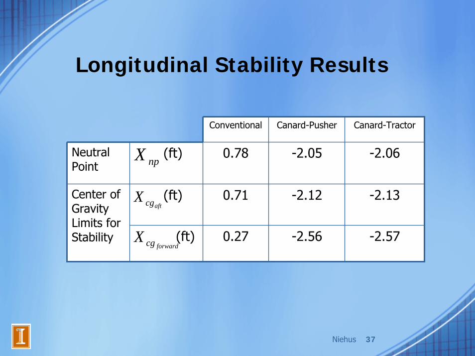
Longitudinal Stability Results
Conventional Canard-Pusher Canard-Tractor
Neutral Point
(ft) 0.78 -2.05 -2.06
(ft) 0.71 -2.12 -2.13Center of Gravity Limits for Stability (ft) 0.27 -2.56 -2.57
npX
aftcgX
forwardcgX
Niehus 38
Future Work in Stability and Control• More detailed control surface sizing analysis• Lateral and directional static stability• Dynamic stability in all axes
Kuester 39
StructuresAdam Kuester
Kuester 40
Structures Overview• V-n diagram and load factor• Materials selection• Aircraft structure• Wing structure• Landing gear• Future work

Kuester 41
V-n Diagram• Design load
factors
• Effect of a more symmetric airfoil
• Nearly identical for conventional and two canards
0 10 20 30 40 50 60 70 80 90 100
-2
-1
0
1
2
3
4
Velocity (mph)
Load
Fac
tor n
Design Load Cruise Gust Load Dive Gust Load Maneuver Load
D
A
E
B
C

Kuester 42
Materials Selection• Consider durability and cost
– Wood • Performance in weather
– Composites• Costs
– Steel• Heavy but strong
– Aluminum• Lighter and commonly
used
• Primarily aluminum– Steel and composite
use
Specific Yield Strength
Wood 8.75 750
Carbon Fiber Composites 52.5 8000
Stainless Steel Alloys
(15-5PH)10 500
Aluminum Alloys(7075)
10 700
43
ksi x10lbm/in
/E ρ⎛ ⎞⎜ ⎟⎝ ⎠ 3
ksilbm/in
⎛ ⎞⎜ ⎟⎝ ⎠
Properties of Various Aircraft Materials

Kuester 43
Aircraft Structure
• Longerons carry bending and axial loads• Bulkheads located at concentrated loads
– Landing gear, hopper, wing spar carrythrough• Stressed skin carries shear and torsional loads

Kuester 44
Wing Structure• Wing box carrythrough
– Most unobtrusive option– Easiest construction
• Wing structure– Two spars
• Quarter chord and aileron support
• Folding Wing– Common in general aviation– Hinge towards rear of wing– One or two person job Cessna Mustang with Folded Wings
http://www.mustangaero.com/Mustang%20II/FoldingWing.html
Kuester 45
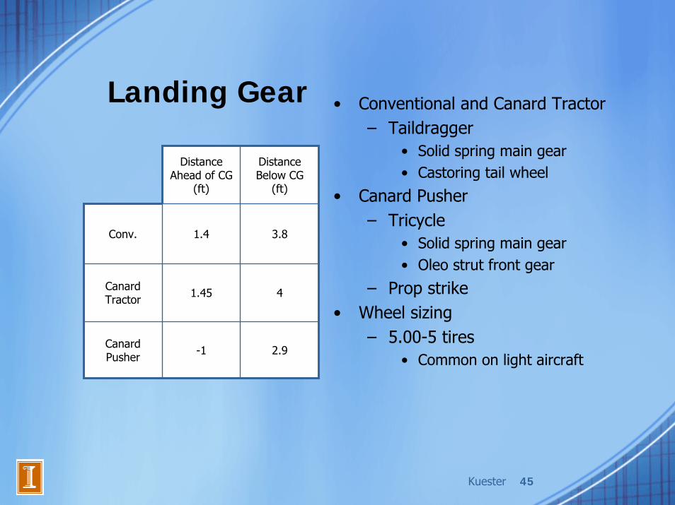
Landing Gear • Conventional and Canard Tractor– Taildragger
• Solid spring main gear• Castoring tail wheel
• Canard Pusher– Tricycle
• Solid spring main gear• Oleo strut front gear
– Prop strike• Wheel sizing
– 5.00-5 tires• Common on light aircraft
Distance Ahead of CG
(ft)
Distance Below CG
(ft)
Conv. 1.4 3.8
Canard Tractor 1.45 4
Canard Pusher -1 2.9

Kuester 46
Future Work in Structures• Fuselage structure
– Determine shape, size, and material of members– Minimize structural weight
• Wing structure– Determine internal structure of ribs, spars, and ailerons– Finalize folding wing design
• Landing gear– Finalize placement, general dimensions, and tire size
• Insure durability of aircraft
Huckshold 47
ConfigurationKevin Huckshold
Huckshold 48
Configuration Objectives• Estimate aircraft weight• Determine internal/external layout• Track CG location throughout mission• Develop CAD model
Huckshold 49
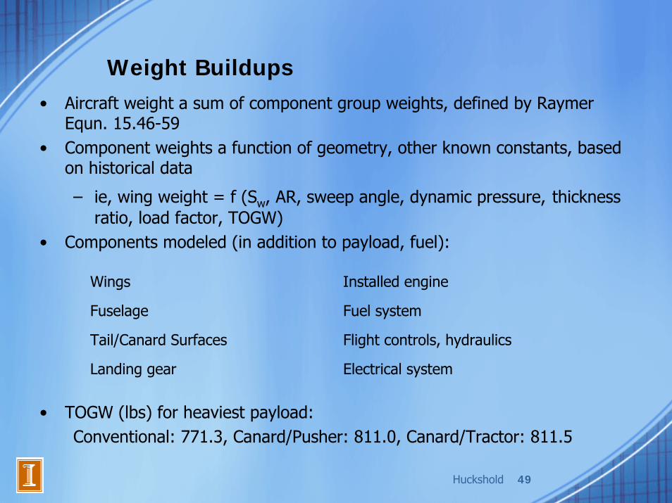
Weight Buildups• Aircraft weight a sum of component group weights, defined by Raymer
Equn. 15.46-59• Component weights a function of geometry, other known constants, based
on historical data
– ie, wing weight = f (Sw, AR, sweep angle, dynamic pressure, thickness ratio, load factor, TOGW)
• Components modeled (in addition to payload, fuel):
• TOGW (lbs) for heaviest payload: Conventional: 771.3, Canard/Pusher: 811.0, Canard/Tractor: 811.5
Wings Installed engine
Fuselage Fuel system
Tail/Canard Surfaces Flight controls, hydraulics
Landing gear Electrical system

Huckshold 50
Configuration
• Wing and empennage sizes, positions relative to CG given by Aero, S&C
• Landing gear location given by Structures• Most other component locations constrained- ie, flight controls must go
on wings, etc.• Motor must go in front (tractor) or in back (pusher)• Challenge- place few remaining components to move CG to desired
location, this defines fuselage length
Huckshold 51
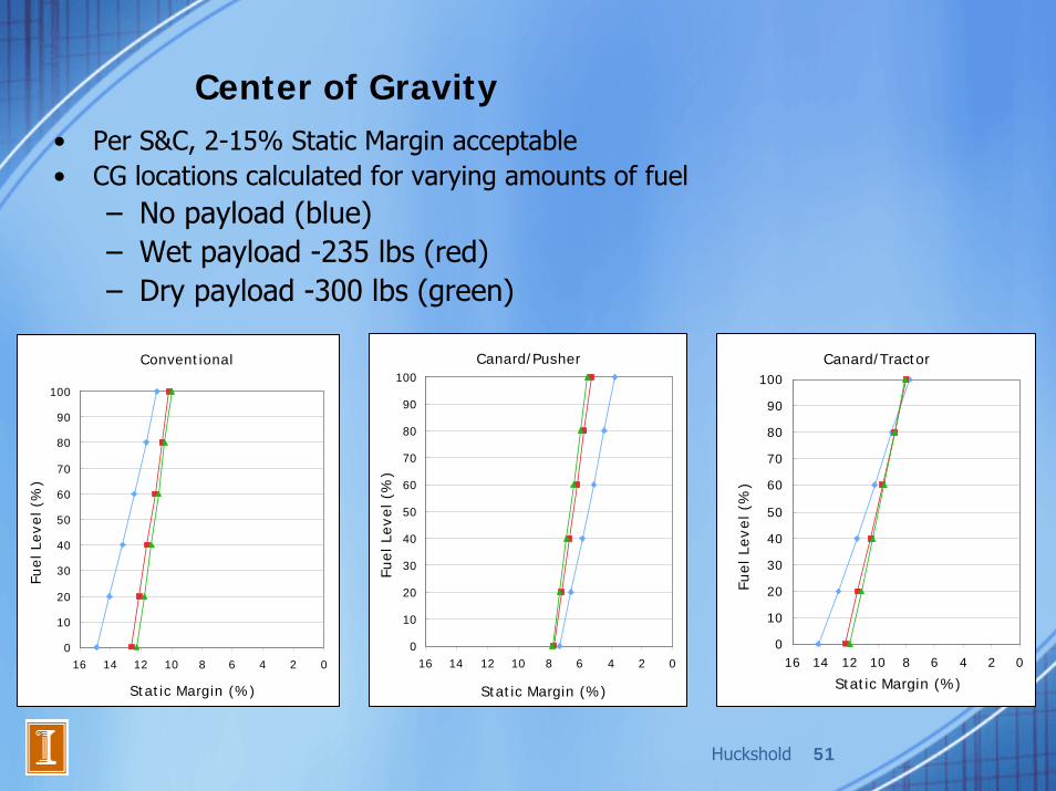
Center of Gravity• Per S&C, 2-15% Static Margin acceptable• CG locations calculated for varying amounts of fuel
– No payload (blue)– Wet payload -235 lbs (red)– Dry payload -300 lbs (green)
Canard/Pusher
0
10
20
30
40
50
60
70
80
90
100
0246810121416
Static Margin (%)
Fuel Le
vel (%
)
Canard/Tractor
0
10
20
30
40
50
60
70
80
90
100
0246810121416
Static Margin (%)
Fuel Le
vel (%
)
Conventional
0
10
20
30
40
50
60
70
80
90
100
0246810121416
Static Margin (%)
Fuel Le
vel (%
)
Huckshold 52
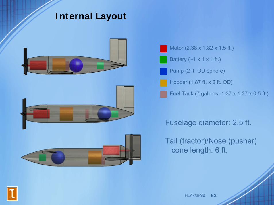
Internal Layout
Motor (2.38 x 1.82 x 1.5 ft.)
Battery (~1 x 1 x 1 ft.)
Pump (2 ft. OD sphere)
Hopper (1.87 ft. x 2 ft. OD)
Fuel Tank (7 gallons- 1.37 x 1.37 x 0.5 ft.)
Fuselage diameter: 2.5 ft.
Tail (tractor)/Nose (pusher) cone length: 6 ft.

Huckshold 53

Huckshold 54
Huckshold 55
Huckshold 56
Future Work in Configuration• Develop more accurate component-based
weight buildup• Continue refining layout, reduce fuselage
length if possible• Calculate vertical CG location, envelope as
payload empties• Calculate moments of inertia

Scott 57
Cost Analysis• Conventional configuration is cheapest• Costs of canards are approximately equal
Fabric Aluminum Composite Fabric Aluminum Composite23550 27450 31150 24950 28850 3255024150 28200 32050 25550 29600 3345024150 28200 32050 25550 29600 33450
Fabric Aluminum Composite Fabric Aluminum Composite28650 32550 36250 27000 30900 3460029250 33300 37150 27600 31650 3550029250 33300 37150 27600 31650 35500
UAV Engines Ltd (AR682)
Conventional/TractorCanard/Tractor
Jabiru Aero Engine (2200A) Rotax (912 UL DCDL)
Canard/Pusher
Zoche Aero-diesels (ZO 03A)
Conventional/TractorCanard/Tractor
Canard/Pusher

Lee 58
Conclusion• Leading configuration: Conventional with
Zoche diesel engine– Cheapest and lightest configuration– Best performance due to lower drag and more
efficient propulsion system– Smallest configuration
• Future Work– Develop more detailed analysis methods– Optimize airplane performance

59
References• [1] “2007 – 2008 AIAA Undergraduate Team Aircraft Design Competition,”
AIAA, 2007.
• [2] Raymer, D. P., Aircraft Design: A Conceptual Approach, 4th ed. AIAA, Reston, VA, 2006.
• [3] Sobester, A., Keane, A., Scanlan, J., and Bresslof, N., “Conceptual Design of UAV Airframes Using a Generic Geometry Service,” AIAA 2005-7079, September 2005.
• [4] Anderson, J. D., Introduction to Flight, 5th ed., McGraw Hill, New York, 2005.
• [5] Bernard Hooper Engineering Ltd [online], http://users.breathe.com/prhooper/ [retrieved 7 November 2007].
• [6] “The Engine Specifications,” Hpower-Ltd [online], http://www.hpower-ltd.com/pages/specifications.htm [retrieved 7 November 2007].
• [7] “Limbach L1700 EA, L2000 EA, L2400 EB, Limbach Flugmotoren [online], www.limflug.de[retrieved 7 November 2007].

60
References• [8] “Zoche Aero-diesels Specifications,” Zoche [online],
http://www.zoche.de/specs.html [retrieved 7 November 2007].
• [9] “Mikron IIIB,” Moravia Inc [online], http://www.moraviation.com[retrieved 7 November 2007].
• [10] UAV Engines [online], http://www.uavenginesltd.co.uk [retrieved 7 November 2007].
• [11] Rotax Aircraft Engines [online], www.rotax-aircraft-engines.com[retrieved 7 November 2007].
• [12] “Jabiru 2200 4 Cylinder 85bhp,” Jabiru Aircraft Engines [online], http://www.jabiru.co.uk/engines.htm [retrieved 7 November 2007].
• [13] “HAE-100 Data Sheet 2,” Howell Aero Engines Limited [online], http://www.howells-aeroengines.co.uk/D2.html [retrieved 7 November 2007].
• [14] “235 Cubic Inch Engine Series,” Lycoming Engines-A Textron Company [online], http://www.lycoming.textron.com/ [retrieved 7 November 2007].

61
References• [15] “DAIR-100 Technical Features,” FTI Diesel Tech, LLC [online],
http://www.dieseltech.cc/techfeatures.htm [retrieved 7 November 2007].
• [16] Kroo, Ilan. "Tail Design and Sizing." Aircraft Aerodynamics and Design Group. Stanford University. 12 Nov. 2007 http://adg.stanford.edu/aa241/stability/taildesign.html.
• [17] Chiles, I., “Structures: V-n Diagrams,” AE 440-A Course Notes, URL: http://courses.ae.uiuc.edu/AE440-A/files/StructuresRefresher.pdf, 2007 [retrieved 13 November 2007].
• [18] Federal Aviation Administration, “FAR Part 23,” Federal Aviation Regulations [online], URL: http://rgl.faa.gov/Regulatory_and_Guidance_Library/rgFAR.nsf/MainFrame? OpenFrameSet [retrieved 14 November 2007].
• [19] Megson, T. H. G., “Principles of Stressed Skin Construction,” Aircraft Structures for Engineering Students, 3rd ed., Butterworth-Heinemann, Oxford, England, 1999, pp. -211-232.
• [20] Broeren, A. P., “Conceptual Design Report-Preliminary Cost Model,” AE440 Aerospace Systems Design I, [handout], 11 October 2007.

62
Any Questions?