Embed Size (px)
Citation preview

© Agrowtek Inc. | www.agrowtek.com | Technology to Help You Grow™1 © Agrowtek Inc. | www.agrowtek.com | Technology to Help You Grow™
Technology to Help You GrowAGROWtEK
DX Series DIN-Rail Mount I/O ModulesDXI8 | DXO8 | DXR6 | DXV4 | DXIO
ContentsIntroduction 2Installation Instructions 4Mounting the Modules 4DXI8 Terminals 5DXO8 Terminals 6DXR6 Terminals 7DXV4 Terminals 8DXIO Terminals 9Input Connections, Discrete Sensors 10Input Connections, Analog Sensors 11Output Connections, DC FETS 12Output Connections, Dry Contacts 13Output Connections, Dry Contacts HVAC 14Output Connections, Analog Voltage 15Output Connections, RJ-45 (Gavita) 16Output Connections, RJ-12 17
Speci�cationsInput Power 9-24Vdc, 1A MAX
Class II / Limited Energy Power Supply
Max Switching Current 1A per point
Max Switching Voltage 24Vdc
Transitor Outputs Sourcing FETS, 1A
PWM on Transistor Outputs 6 Channels, 1kHz
Analog Inputs 0-5Vdc / 0-20mA, 12-BitJumper Selectable
Analog Outputs 0-10Vdc, 10mA max
Analog Sensor Power 5Vdc, 500mA max (onboard)
Enclosure Knock-Outs (2) dia. 7/8”
Enclosure Rating TYPE 12 NEMA
Minimum Cycle Time 1 second
Interface GrowNET™, MODBUS
Terminal Wire Guage 26 - 16 AWG
Tightening Torque 0.3-0.4 Nm
Connection to GrowControl™ GCX 18GrowNET™ Hubs 18
MODBUS RTU 19Serial Speed & Format 19Supported Commands 19Register Types 19MODBUS Holding Registers 20MODBUS Coil Registers 21
Technical Information 22Troublshooting 22Maintenance & Service 22Storage and Disposal 22
Warranty 22
INSTRUCTION MANUAL
DXIO Modules
© Agrowtek Inc. | www.agrowtek.com | Technology to Help You Grow™2
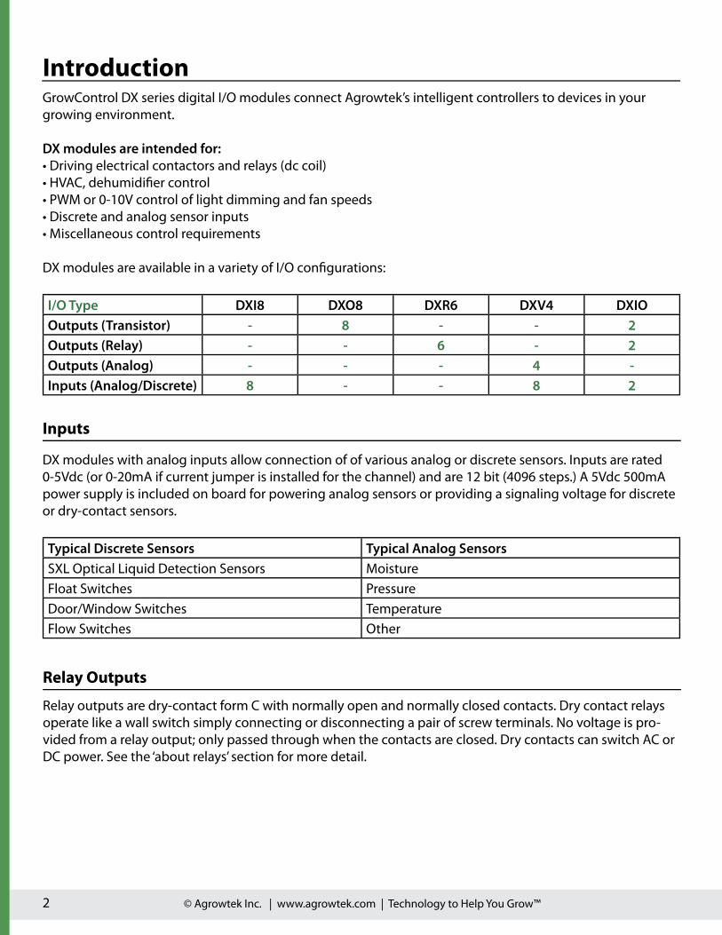
IntroductionGrowControl DX series digital I/O modules connect Agrowtek’s intelligent controllers to devices in your growing environment.
DX modules are intended for:• Driving electrical contactors and relays (dc coil)• HVAC, dehumidifier control• PWM or 0-10V control of light dimming and fan speeds• Discrete and analog sensor inputs• Miscellaneous control requirements
DX modules are available in a variety of I/O configurations:
I/O Type DXI8 DXO8 DXR6 DXV4 DXIOOutputs (Transistor) - 8 - - 2Outputs (Relay) - - 6 - 2Outputs (Analog) - - - 4 -Inputs (Analog/Discrete) 8 - - 8 2
DX modules with analog inputs allow connection of of various analog or discrete sensors. Inputs are rated 0-5Vdc (or 0-20mA if current jumper is installed for the channel) and are 12 bit (4096 steps.) A 5Vdc 500mA power supply is included on board for powering analog sensors or providing a signaling voltage for discrete or dry-contact sensors.
Typical Discrete Sensors Typical Analog SensorsSXL Optical Liquid Detection Sensors MoistureFloat Switches PressureDoor/Window Switches TemperatureFlow Switches Other
Inputs
Relay Outputs
Relay outputs are dry-contact form C with normally open and normally closed contacts. Dry contact relays operate like a wall switch simply connecting or disconnecting a pair of screw terminals. No voltage is pro-vided from a relay output; only passed through when the contacts are closed. Dry contacts can switch AC or DC power. See the ‘about relays’ section for more detail.
© Agrowtek Inc. | www.agrowtek.com | Technology to Help You Grow™3
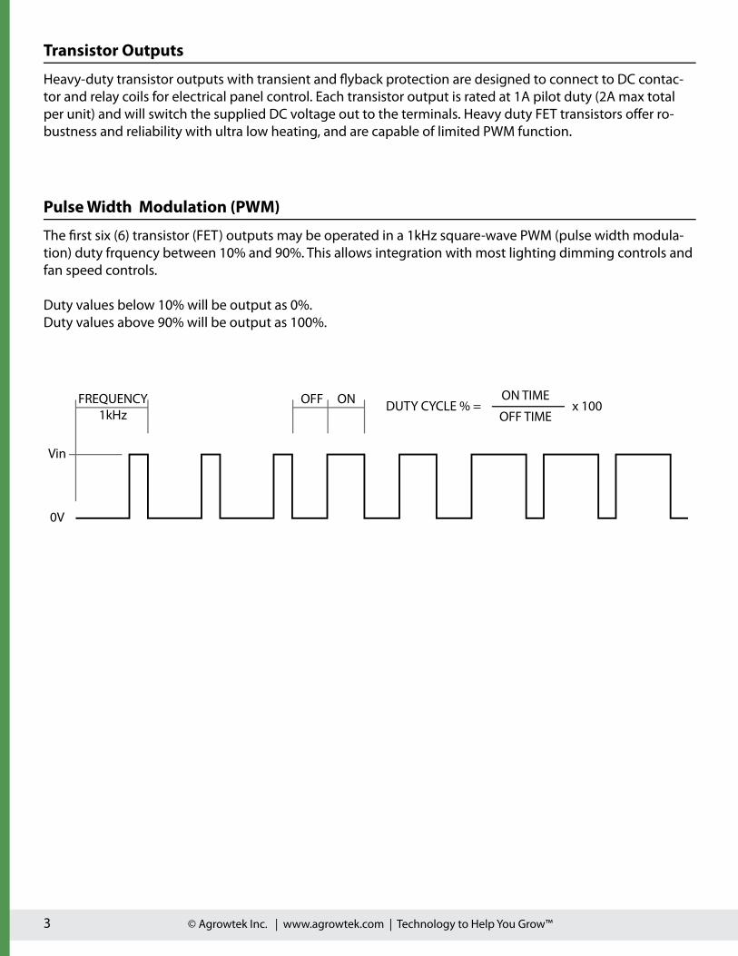
FREQUENCY1kHz
0V
Vin
OFF ON DUTY CYCLE % = ON TIME
OFF TIMEx 100
Pulse Width Modulation (PWM)
The first six (6) transistor (FET) outputs may be operated in a 1kHz square-wave PWM (pulse width modula-tion) duty frquency between 10% and 90%. This allows integration with most lighting dimming controls and fan speed controls.
Duty values below 10% will be output as 0%.Duty values above 90% will be output as 100%.
Transistor Outputs
Heavy-duty transistor outputs with transient and �yback protection are designed to connect to DC contac-tor and relay coils for electrical panel control. Each transistor output is rated at 1A pilot duty (2A max total per unit) and will switch the supplied DC voltage out to the terminals. Heavy duty FET transistors o�er ro-bustness and reliability with ultra low heating, and are capable of limited PWM function.

© Agrowtek Inc. | www.agrowtek.com | Technology to Help You Grow™4
DX series modules are designed for DIN rail mounting in electrical control cabinets and should be enclosed due to the exposed terminal design. If DIN rail is not available, brackets include mounting holes for surface mounting.
Mounting the Modules
Installation Instructions
DANGER Electrocution Hazard Disconnected all power sources before servicing or wiring. For continued protection against electric shock ensure the enclosure is properly grounded at the marked chassis ground terminal. Install all electrical equipment and wiring in accordance with na-
tional and local electric codes. For indoor use in dry locations only (0-80% RH non-condensing.) Replace serviceable parts only with those recommended by Agrowtek Inc.
DANGER Risque d’électrocutionDébranchez toutes les sources d’alimentation avant l’entretien ou le câblage. Pour une protection continue contre les chocs électriques assurer
l’enceinte est correctement reliée à la borne de terre du châssis marquée. Installez tous les équipements électriques et le câblage conformément aux codes électriques nationaux et locaux. Pour une utilisation en intérieur dans des endroits secs seulement (0-80% RH sans condensation.)
Remplacer les pièces réparable seulement avec ceux recommandés par Agrowtek Inc.
Read and follow these instructions to prevent bodily injury or property damage.

© Agrowtek Inc. | www.agrowtek.com | Technology to Help You Grow™5
DXI8 TerminalsDXI8 modules feature eight (8) analog inputs for 0-5V or 0/4-20mA sensors. Inputs can also be used as dis-crete type. An on-board 5Vdc power supply provides up to 500mA of current to drive sensors and for use in discrete sensing applications.
Power is provided to the module via the RJ-45 GrowNET™ port.
1. 5Vdc Power SupplyCommon 5Vdc power supply for driving sensors or for discrete sensing. Both pairs of terminals are supplied by a common 500mA switch mode power supply.
2. Inputs 1-8Sinking inputs measure 0-5Vdc by default. Discrete sensors switch the supplied 5Vdc to an input to trigger it. Inputs may be configured for current sensing (0-20mA) by setting a jumper on the pcb inside of the module.
+5V
GN
D
IN1
IN2
IN3
IN4
+5V
GN
D
IN5
IN6
IN7
IN8
1 2 1 2

© Agrowtek Inc. | www.agrowtek.com | Technology to Help You Grow™6
DXO8 TerminalsDXO8 modules feature eight (8) FET (transistor) outputs for proving DC power. Each fet is capable of 1A with a maximum device total of 8A.
DC power MUST be supplied to the DC power input terminals to power the outputs.Processor may be powered by the GrowNET™ RJ-45 port.
1. VinVin terminals to provide DC power to the output terminals (OUT1 - OUT8). Power must be provided at these terminals to drive the outputs.
2. GNDCommon DC ground terminals for connections.
3. Outputs 1-8Positive sourcing DC transistor outputs for driving solenoids, relays, contactors, etc. with a DC voltage. The first six (6) of the outputs can be configured for PWM control between 10-90% for motor speed control, light diming, etc.
1 2 3 2 3
+ - GN
D
GN
D
OU
T1
OU
T2
OU
T3
OU
T4
GN
D
GN
D
OU
T5
OU
T6
OU
T7
OU
T89 -2 4 V D C
© Agrowtek Inc. | www.agrowtek.com | Technology to Help You Grow™7
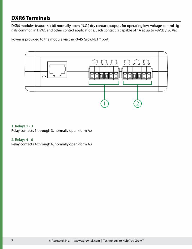
DXR6 TerminalsDXR6 modules feature six (6) normally open (N.O.) dry contact outputs for operating low-voltage control sig-nals common in HVAC and other control applications. Each contact is capable of 1A at up to 48Vdc / 36 Vac.
Power is provided to the module via the RJ-45 GrowNET™ port.
1. Relays 1 - 3Relay contacts 1 through 3, normally open (form A.)
2. Relays 4 - 6Relay contacts 4 through 6, normally open (form A.)
1 2
1 1 2 2 3 3 4 4 5 5 6 6

© Agrowtek Inc. | www.agrowtek.com | Technology to Help You Grow™8
DXV4 TerminalsDXV4 modules feature four (4) analog 0-10Vdc outputs for operating ballast dimming signals, variable speed drives, and other devices with a analog voltage control input.
Power is provided to the module via the RJ-45 GrowNET™ port.
1. GNDCommon DC ground terminals for connections.
2. Analog Outputs 1-4Sinking/Sourcing DC outputs for driving lighting dimming controls and other equipment with a 0-10Vdc analog input. Each channel is capable of driving up to 50 light fixtures (50mA max. per channel.)
1 2
GN
D
GN
D
OU
T1
OU
T2
OU
T3
OU
T4
© Agrowtek Inc. | www.agrowtek.com | Technology to Help You Grow™9
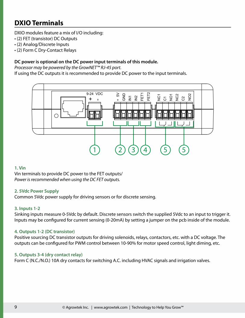
DXIO TerminalsDXIO modules feature a mix of I/O including:• (2) FET (transistor) DC Outputs• (2) Analog/Discrete Inputs• (2) Form C Dry-Contact Relays
DC power is optional on the DC power input terminals of this module.Processor may be powered by the GrowNET™ RJ-45 port.If using the DC outputs it is recommended to provide DC power to the input terminals.
1. VinVin terminals to provide DC power to the FET outputs/Power is recommended when using the DC FET outputs.
2. 5Vdc Power SupplyCommon 5Vdc power supply for driving sensors or for discrete sensing.
3. Inputs 1-2Sinking inputs measure 0-5Vdc by default. Discrete sensors switch the supplied 5Vdc to an input to trigger it. Inputs may be configured for current sensing (0-20mA) by setting a jumper on the pcb inside of the module.
4. Outputs 1-2 (DC transistor)Positive sourcing DC transistor outputs for driving solenoids, relays, contactors, etc. with a DC voltage. The outputs can be configured for PWM control between 10-90% for motor speed control, light diming, etc.
5. Outputs 3-4 (dry contact relay)Form C (N.C./N.O.) 10A dry contacts for switching A.C. including HVAC signals and irrigation valves.
1 2 3 5 5
+ - +5V
GN
D
IN1
IN2
FET1
FET2
NC
1
C1
NO
1
NC
2
C2 NO
29 -2 4 V D C
4

© Agrowtek Inc. | www.agrowtek.com | Technology to Help You Grow™10
1. SXL Optical Liquid Sensor (powered sensor)Requires three wires; V+, GND and signal output. Connect the output of the sensor to the desired input terminal.
2. Float Switch (dry contact sensor)Requires two wires; V+ and signal output. Connect the output of the sensor to the desired input terminal.
Input Connections, Discrete SensorsDiscrete type sensors o�er only an indication of “true” or “false” and no information in between. Typical examples include liquid presense detection sensors, manual and proximity switches, door and window switches, etc.
Passive SensorsPassive sensors are simple, typically mechanical sensors that manipulate a physical switch (dry contact) to close a circuit. Passive sensors do not have any electronics on board and simply pass through the signal voltage when the condition is true. Passive sensors only require two wires; the signal voltage and the sensor output.
Active SensorsActive sensors have electronics on board and require both a power and ground wire to operate the sensor, plus a third wire to carry the output signal of the sensor.
+ 5 V
GND
I N1
I N2
I N3
I N4
+ 5 V
GND
I N5
I N6
I N7
I N8
1
2

© Agrowtek Inc. | www.agrowtek.com | Technology to Help You Grow™11
Input Connections, Analog SensorsAnalog sensors o�er a “variable” value such as a temperature, pressure, etc. The device’s analog inputs are 12 bit and o�er 4096 steps of resolution (1.22mV or 0.005mA.) Each input has a default range in “Voltage” mode of 0-5Vdc, or if set with a jumper to a “Current” mode, a 0-20mA range.
Voltage ModeStandard mode for 0-5Vdc analog sensors or discrete type sensors.
Current ModeMode for 0-20mA or 4-20mA type industrial analog sensors.Note: Jumpers must be installed on the PCB for mA mode.
+ 5 V
GND
I N1
I N2
I N3
I N4
+ 5 V
GND
I N5
I N6
I N7
I N8
1
2
Red (v+)Bare (v-)Black (signal)
0 - 5 VdcSensor
VinGNDVout (0-5V)
1. SXM-1 Soil Moisture Sensor (0-5V)Requires three wires; V+, GND and signal output. Connect the output of the sensor (black wire) to the desired input terminal.
2. 0-5V DC SensorAny standard three-wire 0-3V or 0-5V sensor can be integrated into a DXI8 module.

© Agrowtek Inc. | www.agrowtek.com | Technology to Help You Grow™12
1. Electromechanical Relays & ContactorsDC powered relays and contactors with magnetic coils may be driven directly by the outputs. Each output is protected for �yback and surge, and is capable of up to 1A continuous current (1A max combined current.)
2. Solid State RelaysDC powered solid state relays (SSR’s) may be driven by the DC output terminals.
Output Connections, DC FETSHigh current FET (transistor) outputs control DC loads. DXO8 and DXIO modules switch the voltage that is supplied to the unit at the Vin terminal block to the DC output terminals. Power is required at the Vin termi-nal block to supply the outputs with power. The default power supply is 24Vdc. Lower voltage may be sup-plied to the board (down to 9Vdc) depending on the requirements of the devices being driven.
DC Power Supply
(required)
1
V+DC GND
Brea
ker
Load
+-
GND
GND
OUT1
OUT2
OUT3
OUT4
GND
GND
OUT5
OUT6
OUT7
OUT8
9-24 VDC
C1 C2
Brea
ker
Load
SSR
2

© Agrowtek Inc. | www.agrowtek.com | Technology to Help You Grow™13
1. Irrigation Solenoid Valves24VAC irrigation and gas valves can be controlled by switching power supplied by a step-down transformer. 24VAC is safer and more common than line-voltage for water/irrigation solenoids.
2, A.C. Coil Relays & ContactorsContactors and relays with 24VAC coils can be operated by controlling the power from a transformer to the magnet coil with a dry contact switch.
Output Connections, Dry ContactsDry-contact relays consist of a mechanical switch (contact) and an electro-magnet to turn-on (close) the switch contact. A spring opens the switch when the electromagnet is no longer powered. The contact switch operates the same way as a wall-switch, connecting two screw terminals together. Dry contacts are typically used for switching low-voltage AC control signals including HVAC units and irrigation solenoids.
1
2
C1 C2
Brea
ker
Load
1
1
2
2
3
3
4
4
5
5
6
6
TransformerL
N
24V AC
TransformerL
N
24V AC

© Agrowtek Inc. | www.agrowtek.com | Technology to Help You Grow™14
1. HVAC FCUTypical example of connections to a RTU (roof top unit) HVAC system FCU (furnace control unit.)
2. Humidi�ers & Dedumidi�ersCommercial humidifiers and dehumidifiers typically provide both an economical internal humidistat control and terminals for external humidistat control. Contact your equipment manufacturer or review your equip-ment installation manual for details on which connections to make for dry-contact external control.
Output Connections, Dry Contacts HVACHVAC units typically supply 24VAC from a built-in control transformer located in the HVAC unit. The 24VAC supplied by the FCU is switch to the various control signal wires back to the FCU inputs activating the HVAC unit. Dry contacts are required to switch the AC control voltage in HVAC and commercial dehumidifier units.
1
2
1
1
2
2
3
3
4
4
5
5
6
6
RcG
24VacFan
W Heat
Y1 Cool 1
Y2 Cool 2
FurnaceControl
Unit
Dehumidi�er
DH (Anden) BLU/23 (Quest)DH (Anden) YLW/11 (Quest)

© Agrowtek Inc. | www.agrowtek.com | Technology to Help You Grow™15
1. Dimmable Ballasts & VFD Motor ControllersBallasts and VFD controllers that accept a 0-10V signal may be controlled by one of four (4) analog voltage output channels. Each of the four channels may be set to 0-10Vdc independently. Internal feedback sensing manages voltage levels automatically accounting for unit loading.
Output Connections, Analog VoltageAnalog voltage outputs are designed for analog signal control primarily in light dimming and speed control applications. Power is required at the Vin terminal block to supply the outputs with power. The power supply must be in the range of 12-24Vdc. Up to 50 fixtures (typical) may be driven from a single output channel.
1
DIMDIM
GND
GND
OUT1
OUT2
OUT3
OUT4

© Agrowtek Inc. | www.agrowtek.com | Technology to Help You Grow™16
1. Gavita RJ-45Gavita ballasts that use RJ45 connections have the same standard pin-out as RJ-12/14 connectors utilizing the center four pin connections.
Output Connections, RJ-45 (Gavita)Gavita fixtures use a RJ-45 connector.
The connections from a standard RJ-45 connector to the DXV4 are detailed below.
Eaxmple shows connection to output channel #3.
GND
GND
OUT1
OUT2
OUT3
OUT4
RJ-45

© Agrowtek Inc. | www.agrowtek.com | Technology to Help You Grow™17
1. 0-10V RJ-12Gavita ballasts that use RJ12 or similar “phone” cord modular jack connections have a standard pin-out using the center to pins as DC- (GND) and the two pins outside of the center pins as DC+ (0-10V).
Output Connections, RJ-12Gavita, Grower’s Choice, Luxx Lighting, and may other 0-10V dimmable fixtures use RJ-12 or similar style “phone” cord modular connectors.
The connections from a standard RJ-12 style connector to the DXV4 are detailed below.
GND
GND
OUT1
OUT2
OUT3
OUT4RJ-11, RJ-12If 6-wire cable, do not use outer wires.

© Agrowtek Inc. | www.agrowtek.com | Technology to Help You Grow™18
GrowNET™ Hubs
All GrowNET™ devices are connected using standard CAT5 Ethernet cable with RJ-45 connections.
Devices can be connected directly to the GrowNET™ ports on the bottom of the controller, or through HX8 GrowNET™ hubs. It is typical to simplify cabling by locating hubs centrally in hall ways and rooms allowing single runs from an 8-port device hub back to a central hub or back to the controller.
HX8 GrowNET ™ hubs expand a single port into eight more ports. Hubs can be daisy-chained to form a network of up to 100 devices per GrowNET™ bus. Individually bu�ered port transcievers provide excellent signal integrity and extended communication strength and range.
Hubs provide up to 1A of power for operating sensors and most relays directly over the CAT5 cable. A DC jack on the hub provides 24Vdc power to the ports from the included wall power supply. A terminal block power option is also available.
DIELECTRIC GREASEDielectric grease is recommended on RJ-45 GrowNET™ connections when used in humid environments. Place a small amount of grease onto the RJ-45 plug contacts before inserting into the GrowNET™ port.Non-conductive grease is designed to prevent corrosion from moisture in electrical connectors.
• Loctite LB 8423 • Dupont Molykote 4/5 • CRC 05105 Di-Electric Grease• Super Lube 91016 Silicone Dielectric Grease • Other Silicone or Lithium based insulating grease
NOTICEGrowNET™ ports use standard RJ-45 connections but are NOT compatible the Ethernet network equipment. Do not connect GrowNET™ ports to Ethernet ports or network switch gear.
Installation Notes
Refer to the GCX controller manual for details on adding the device to the system.
Connection to GrowControl™ GCX

© Agrowtek Inc. | www.agrowtek.com | Technology to Help You Grow™19
Serial Speed & Format
Data registers are 16 bits wide with addresses using the standard MODICON protocol. Floating point values use the standard IEEE 32-bit format occupying two contiguous 16 bit registers. ASCII values are stored with two characters (bytes) per register in hexadecimal format. Coil registers are single bit values which control and indicate the status of a relay; 1 = on, 0 = o�.
Register Types
0x01 Read Coils0x03 Read Multiple Registers0x05 Write Single Coil0x06 Write Single Register0x15 Write Multiple Coils
A request to use a function that is not available will return an illegal function error (0x01).
Supported Commands
MODBUS RTURS-485Use the LX2 ModLINK to connect MODBUS devices to the GrowNET™ port.
R J 4 5 / CA T5
7 - 24 Vdc
3.3/5Vdc Serial Bus Compatible.I n c l u d e req u i red b u s t erm i n a t i n g resi st ors p er EI A st a n d a rd .
TX/RX+
TX/RX-
P L C
RS-485
The default serial data format for the LX2 ModLINK interface is: 19,200 baud, 8-N-1.
Alternate speeds and formats between 9,600 - 115,200 baud may be configured with the free AgrowLINK PC utility using a LX1 USB AgrowLINK and the cross-over adapter supplied with the LX2 ModLINK.
LX2 ModLINK™LX1 USB AgrowLINK™
GrowNET™Cross-Over
7 - 24 VdcUSB
Cross-Over

© Agrowtek Inc. | www.agrowtek.com | Technology to Help You Grow™20
MODBUS Holding RegistersParameter Description Range Type Access Address
Address Device Slave Address 1 - 247 8 bit R/W 40001
Serial# Device Serial Number ASCII 8 char R 40004
DOM Date of Manufacture ASCII 8 char R 40008
HW Version Hardware Version ASCII 8 char R 40012
FW Version Firmware Version ASCII 8 char R 40016
Device Model Product Model Number ASCII 8 char R 40020
Analog Input Value,Integer
Input 1
Signed Int 16 bit, signed R
40101
Input 2 40102
Input 3 40103
Input 4 40104
Input 5 40105
Input 6 40106
Input 7 40107
Input 8 40108
Analog Input Value,Floating Point
Input 1
Floating Point 32 bit, �oat R
40201
Input 2 40203
Input 3 40205
Input 4 40207
Input 5 40209
Input 6 40211
Input 7 40213
Input 8 40215
PWM Output,Duty Cycle %
Output 1
0-100 16 bit, signed R/W
40301
Output 2 40302
Output 3 40303
Output 4 40304
Output 5 40305
Output 6 40306
Timeout (seconds) Turn o� outputs if no communication 0 - 32767 16 bit, unsigned R/W 41001
Output Closure Count,Discrete
Output 1
Unsigned Int 32 bit, unsigned R
49001
Output 2 49003
Output 3 49005
Output 4 49007
Output 5 49009
Output 6 49011
Output 7 49013
Output 8 49015

© Agrowtek Inc. | www.agrowtek.com | Technology to Help You Grow™21
MODBUS Coil RegistersParameter Access Address
Relay 1 R/W 1
Relay 2 R/W 2
Relay 3 R/W 3
Relay 4 R/W 4
Relay 5 R/W 5
Relay 6 R/W 6
Relay 7 R/W 7
Relay 8 R/W 8
A request to read or write coils/registers that are not available will return an illegal address error (0x02.)

© Agrowtek Inc. | www.agrowtek.com | Technology to Help You Grow™22
Technical Information
Agrowtek Inc. warrants that all manufactured products are, to the best of its knowledge, free of defective material and workmanship and warrants this product for 1 year from the date of purchase. This warranty is extended to the original purchaser from the date of receipt. This warranty does not cover damages from abuse, accidental breakage, or units that have been modified, altered, or installed in a manner other than that which is specified in the installation instructions. Agrowtek Inc. must be contacted prior to return ship-ment for a return authorization. No returns will be accepted without a return authorization. This warranty is applicable only to products that have been properly stored, installed, and maintained per the installation and operation manual and used for their intended purpose. This limited warranty does not cover products installed in or operated under unusual conditions or environments including, but not limited to, high hu-midity or high temperature conditions. The products which have been claimed and comply with the afore-mentioned restrictions shall be replaced or repaired at the sole discretion of the Agrowtek Inc. at no charge. This warranty is provided in lieu of all other warranty provisions, express or implied. It is including but not limited to any implied warranty of fitness or merchantability for a particular purpose and is limited to the Warranty Period. In no event or circumstance shall Agrowtek Inc. be liable to any third party or the claimant for damages in excess of the price paid for the product, or for any loss of use, inconvenience, commercial loss, loss of time, lost profits or savings or any other incidental, consequential or special damages arising out of the use of, or inability to use, the product. This disclaimer is made to the fullest extent allowed by law or regulation and is specifically made to specify that the liability of Agrowtek Inc. under this limited warranty, or any claimed extension thereof, shall be to replace or repair the Product or refund the price paid for the Product.
Warranty
Exterior CleaningExterior may be wiped with a damp cloth wish mild dish detergent, then wiped dry. Disconnect power be-fore cleaning the enclosure to prevent electrical shock.
Maintenance & Service
Storage and Disposal
Outputs are not activating, LED does not �ashThe status LED will �ash three times on power-up and each time data is transmitted.Ensure the input power has 9-24Vdc and are correctly wired for polarity.
Troublshooting
StorageStore equipment in a clean, dry environment with ambient temperature between10-50°C.
DisposalThis indsutrial control equipment may contain traces of lead or other metals and environmental contami-nants and must not be discarded as unsorted municipal waste, but must be collected separately for the purpose of treatment, recovery and environmentally sound disposal. Wash hands after handling internal components or PCB’s.