Embed Size (px)
Citation preview

7/23/2019 AH4000 Multi General INE-851B (1)
http://slidepdf.com/reader/full/ah4000-multi-general-ine-851b-1 1/121
INST.No. INE-851B
AH4000 (Multi-point type)
Hybrid Memory Recorder[ General ]
7/23/2019 AH4000 Multi General INE-851B (1)
http://slidepdf.com/reader/full/ah4000-multi-general-ine-851b-1 2/121
1. Introduction .................................................................................................................... 1
2. For Safe Use ................................................................................................................... 4
2-1.
Preconditions for Use ......................................................................................................................................... 4
2-2.
Symbol Mark....................................................................................................................................................... 4
2-3.
Label .......................................................... ................................................................. ........................................ 4
2-4.
Important Explanation ................................................................ ............................................................... .......... 5
3. Model Code List ............................................................................................................. 6
4. Mounting and Wiring ..................................................................................................... 7
4-1.
External Dimensions ........................................................ .............................................................. ..................... 7
4-2.
Mounting ............................................................... ................................................................. ............................. 7
4-3.
Wiring ................................................................................................................................................................. 9
5. Part Names ................................................................................................................... 27
5-1.
Front Section of Internal Unit ......................................................................................................... ................... 27
5-2.
Operation/Set Keys .......................................................................................................................................... 27
6. Operation ...................................................................................................................... 28
6-1.
Preparation for Operation .............................................................................................................. ................... 28
6-2.
Basic Operation ............................................................... ................................................................. ................ 30
6-3.
Operation .............................................................. ................................................................. ........................... 33
7. Factory Default Settings .............................................................................................. 37
7-1.
List of Factory Default Settings ............................................................. ............................................................ 37
8. Setting Method ............................................................................................................. 38
8-1.
Basic Rules....................................................................................................................................................... 38
8-2.
Input Type Settings “Range” ................................................................. ............................................................ 40
8-3.
Alarm Settings “Alarm” ....................................................................................................... .............................. 43 8-4.
Calculation Settings “Calc” ............................................................................................................................... 50
8-5.
Formula Settings “Formula” ........................................................ .............................................................. ........ 54
8-6.
Broken Line Approximation Table Settings “Seg.Tbl” ............................................................. ........................... 61
8-7.
Chart Speed Settings “Chart” ........................................................................................................................... 62
8-8.
Dot Printing Settings “Dot” .......................................................... .............................................................. ........ 63
8-9.
Subtract Printing Settings “Sub Prt” ................................................................. ................................................. 64
8-10.
Dot Printing Interval Settings “Dot.Int” ............................................................. ................................................. 66
8-11.
Periodic (Data Interval) Data Printing Settings “DataInt”................................................................................... 67
8-12.
Periodic (Specified Time) Data Printing Settings “PrtTime” ............................................................... ................ 68
8-13.
List Printing Settings “ListPrt” ........................................................................................................................... 69
8-14.
Message Printing 1 Settings “MsgPrt1” ............................................................................................................ 70
8-15.
Message Printing 2 Settings “MsgPrt2” ............................................................................................................ 71 8-16.
Recording Format Settings “PrtForm” .............................................................. ................................................. 72
8-17.
Auto Range Settings “A.Range” ........................................................... ............................................................ 73
8-18.
Compressed/Expanded Printing Settings “Cmp&Exp” ........................................................... ........................... 75
8-19.
Zone Printing Settings “ZonePrt” ........................................................................................... ........................... 77
8-20.
SD Card “SD CARD” .......................................................................................................... .............................. 79
8-21.
USB Engineering Port Settings “USB” ............................................................. ................................................. 85
8-22.
Calendar Timer Settings “Timer” ........................................................... ............................................................ 86
8-23.
Fail Output Settings “FailOut” ................................................................ ........................................................... 87
8-24.
Display Settings “Display” ........................................................... .............................................................. ........ 89
8-25.
Measured Value Display Order Settings “D.Order” ................................................................ ........................... 90
8-26.
Date and Time Settings “Date” ........................................................................ ................................................. 91
8-27.
System Settings “System” ................................................................................................................................ 92 8-28.
System Information Display “SysInfo” .............................................................. ................................................. 93
9. Adjustment ................................................................................................................... 94
9-1.
Trace Printing (Dot Printing) Position Adjustment “Rec Adj” ............................................................................. 94
Table of contents
7/23/2019 AH4000 Multi General INE-851B (1)
http://slidepdf.com/reader/full/ah4000-multi-general-ine-851b-1 3/121
9-2.
Input Adjustment “Inp Adj” .......................................................................................... ...................................... 95
9-3.
Input Shift Adjustment ................................................................ ............................................................... ........ 96
9-4.
Wiring and Environment for Input Adjustment....................................... ............................................................ 97
10. Engineering Port (Mini-USB Terminal) ..................................................................... 98
11. Troubleshooting......................................................................................................... 99
11-1.
Problems and Remedies .................................................................................................................................. 99
11-2.
Abnormal Measured Value ......................................................................................... .................................... 100
12. Inspection and Maintenance ................................................................................... 101
12-1.
Routine Inspection ........................................................... ................................................................. .............. 101
12-2.
Consumable Parts and Replacement Guideline ......................................................... .................................... 101
12-3.
The battery removal method for the purpose of disposal ................................................................ ................ 102
13. Option ....................................................................................................................... 104
13-1.
External Operation Settings “Dig Inp” ............................................................................................... .............. 104
13-2.
Operation Recording Settings “Ope.Rec” ........................................................ ............................................... 107
13-3.
COM Port Settings “COM1” and “COM2” ....................................................................................................... 108
13-4.
IP Address etc… Settings “Ether” .................................................................................................. ................. 109
13-5.
SNTP Settings “SNTP” .................................................................................................................. ................. 110
13-6.
E-mail Settings “E-mail” .............................................................. .............................................................. ....... 111
14. Specifications ........................................................................................................... 114
7/23/2019 AH4000 Multi General INE-851B (1)
http://slidepdf.com/reader/full/ah4000-multi-general-ine-851b-1 4/121
- 1 -
1. Introduction
Thank you for purchasing AH4000 sesries (Multi-point Type) with 180mm recording width.This industrial use instrument records input signals to the chart paper and stores data into the SD card.Mount this instrument on the indoor instrumentation panel etc. and record signals of temperature sensor, pressure gauge,hygrometer and flow meter. Reading signals of the recorder are thermocouple, resistance thermometer, DCmV and DCV. Make sure to read this instruction manual in advance to understand this unit well and prevent troubles from occurring. Thismanual is a “General” Instruction manual. For specifications with communications, read the “Communications” instructionmanual separately.
- To the persons doing instrumentation, installation, and sales -
Make sure to provide this instruction manual to the person who uses the unit.
- To the users of this unit -
Store this instruction manual with care until you scrap the unit. Also, write down the parameter contents set in the product and keep it for your record.
Request
1. No part of this manual can be reproduced or copied in any form without permission.2. The contents of this manual may be altered without prior notice.3. This manual has been documented by making assurance doubly sure. However, if any question arises or if any
error, an omission, or other deficiencies are found, please contact your nearest our sales office.4. CHINO is not responsible for any operation results of this software.
Notice
1. Microsoft, Windows, Windows XP, Windows Vista, Windows 7, and NET Framework are trademarks of MicrosoftCorporation and the related company.
2. SD Memory Card is the trademark of Panasonic Corporation, SanDisk Corporation in USA, and TOSHIBACORPORATION.
3. Other described company names and product names are trademarks and registered products of the respectivecompanies.
4. Please note that the marks “TM” and “®” are omitted throughout this manual.
Trademark
Per chlorate MaterialThis instrument uses battery with Perchlorate Material.Special handling may apply, seehttp://www. dtsc.ca.gov/hazardouswaste/perchiorate
Warning
This product is warranted for one year from the date of delivery. If it is damaged during the warranty period, whenused normally based on the cautions in the instruction manual labels attached to the product, etc., it will be repairedwithout any charge (only in Japan). In the case, we are sorry to trouble you, but please contact your dealer ornearest our sales office.However, in cases of the followings, it will be repaired at your expense even during warranty period.1. Failure or damage caused by improper use or connection, or invalid repair or modification.2. Failure or damage caused by fire, earthquake, wind or flood, thunderbolt, or other extraordinary natural
phenomena, or pollution, salt, harmful gas, abnormal voltage, or use of unspecified power.3. Replacement of parts or accessories that have reached the end of their life.Furthermore, the term „warranty‟ in this sense covers only a CHINO‟s product itself. Therefore, we are not
responsible for compensation for whatever the damage that is triggered by failure of our product.
Product warranty scope
7/23/2019 AH4000 Multi General INE-851B (1)
http://slidepdf.com/reader/full/ah4000-multi-general-ine-851b-1 5/121
- 2 -
Before use
Make sure to check the following before use after unpacking the unit. If you have any question, please contact your dealeror our nearest office.
1. Exterior checkCheck that the appearance of the product has no damage.
2. Model code checkCheck that the model code of the purchased product is correct.
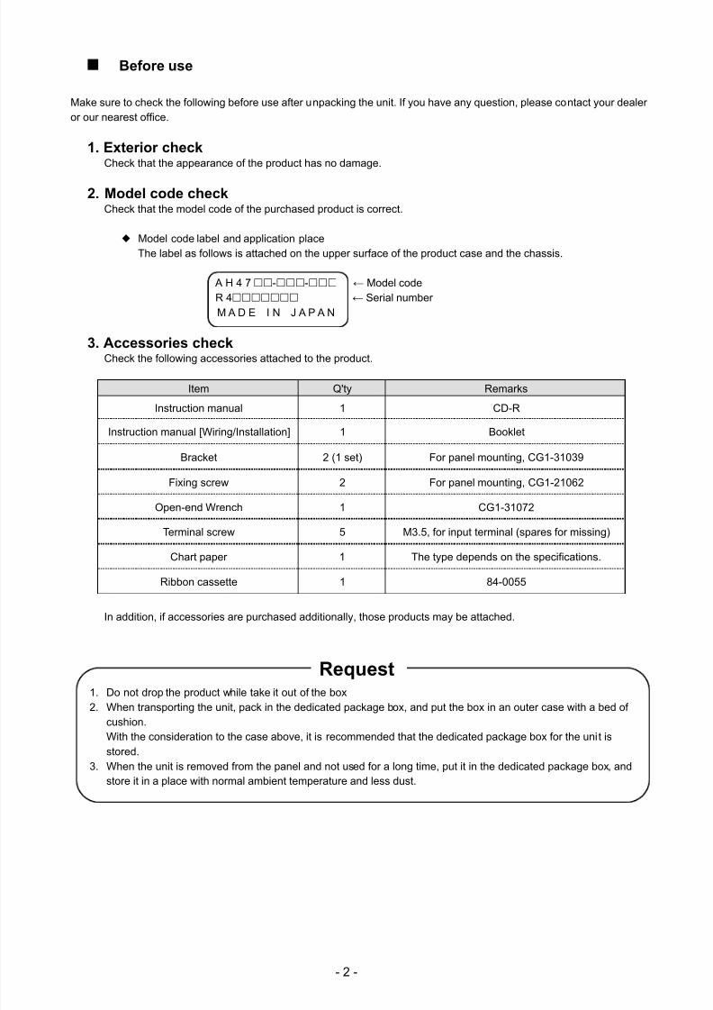
Model code label and application placeThe label as follows is attached on the upper surface of the product case and the chassis.
A H 4 7-- ← Model codeR 4 ← Serial numberM A D E I N J A P A N
3. Accessories checkCheck the following accessories attached to the product.
Item Q'ty Remarks
Instruction manual 1 CD-R
Instruction manual [Wiring/Installation] 1 Booklet
Bracket 2 (1 set) For panel mounting, CG1-31039
Fixing screw 2 For panel mounting, CG1-21062
Open-end Wrench 1 CG1-31072
Terminal screw 5 M3.5, for input terminal (spares for missing)
Chart paper 1 The type depends on the specifications.
Ribbon cassette 1 84-0055
In addition, if accessories are purchased additionally, those products may be attached.
1. Do not drop the product while take it out of the box
2. When transporting the unit, pack in the dedicated package box, and put the box in an outer case with a bed ofcushion.With the consideration to the case above, it is recommended that the dedicated package box for the unit isstored.
3. When the unit is removed from the panel and not used for a long time, put it in the dedicated package box, andstore it in a place with normal ambient temperature and less dust.
Request
7/23/2019 AH4000 Multi General INE-851B (1)
http://slidepdf.com/reader/full/ah4000-multi-general-ine-851b-1 6/121
- 3 -
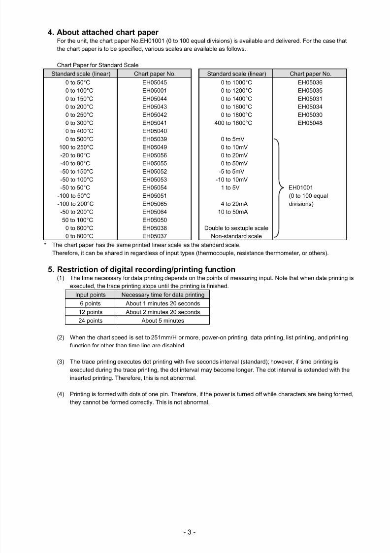
4. About attached chart paperFor the unit, the chart paper No.EH01001 (0 to 100 equal divisions) is available and delivered. For the case thatthe chart paper is to be specified, various scales are available as follows.
Chart Paper for Standard Scale
Standard scale (linear) Chart paper No. Standard scale (linear) Chart paper No.
0 to 50°C0 to 100°C
0 to 150°C0 to 200°C0 to 250°C0 to 300°C0 to 400°C0 to 500°C
100 to 250°C-20 to 80°C-40 to 80°C-50 to 150°C-50 to 100°C-50 to 50°C
-100 to 50°C-100 to 200°C-50 to 200°C50 to 100°C
0 to 600°C0 to 800°C
EH05045EH05001
EH05044EH05043EH05042EH05041EH05040EH05039EH05049EH05056EH05055EH05052EH05053EH05054
EH05051EH05065EH05064EH05050EH05038EH05037
0 to 1000°C0 to 1200°C
0 to 1400°C0 to 1600°C0 to 1800°C
400 to 1600°C
0 to 5mV0 to 10mV0 to 20mV0 to 50mV
-5 to 5mV-10 to 10mV
1 to 5V
4 to 20mA10 to 50mA
Double to sextuple scaleNon-standard scale
EH05036EH05035
EH05031EH05034EH05030EH05048
EH01001
(0 to 100 equaldivisions)
* The chart paper has the same printed linear scale as the standard scale.Therefore, it can be shared in regardless of input types (thermocouple, resistance thermometer, or others).
5. Restriction of digital recording/printing function(1) The time necessary for data printing depends on the points of measuring input. Note that when data printing is
executed, the trace printing stops until the printing is finished.
Input points Necessary time for data printing
6 points About 1 minutes 20 seconds
12 points About 2 minutes 20 seconds
24 points About 5 minutes
(2) When the chart speed is set to 251mm/H or more, power-on printing, data printing, list printing, and printingfunction for other than time line are disabled.
(3) The trace printing executes dot printing with five seconds interval (standard); however, if time printing isexecuted during the trace printing, the dot interval may become longer. The dot interval is extended with theinserted printing. Therefore, this is not abnormal.
(4) Printing is formed with dots of one pin. Therefore, if the power is turned off while characters are being formed,they cannot be formed correctly. This is not abnormal.

7/23/2019 AH4000 Multi General INE-851B (1)
http://slidepdf.com/reader/full/ah4000-multi-general-ine-851b-1 7/121
- 4 -
2. For Safe Use
If the unit is used in a manner not specified by manufacturer, the protection provided by the unit may be impaired.For safe use of the unit, please read and understand the following cautions.
2-1. Preconditions for Use
The unit is a component type general product to be used mounted on an indoor instrumentation panel. Avoid using underother conditions.Use after the system safety is implemented such as the fail-safe design and periodical inspection on the final product side. Also, for wiring/adjustment/operation of the unit, ask professionals with instrumentation knowledge to perform.Furthermore, also the person who actually uses the unit is required to read this instruction manual to fully understandvarious cautions and basic operation.
2-2. Symbol Mark
This instruction manual includes the following symbol marks. Make sure to fully understand the meaning of them.
Symbol mark Meaning
Cautions are explained to avoid causes for death or serious injuries of users.
Cautions are explained to avoid causes for slight injuries of users or damages of the unitor peripheral devices.
2-3. Label
For safe use of the unit, the following labels are used.
Label ”Name” and place Meaning
“Alert symbol mark”Various terminals
(back side)
Place to be handled with cautions to avoid “electricshock”, “injuries”, etc.
“Protective conductorterminal”
Right side of power terminal(back side)
Terminal to be grounded to avoid electric shock
100 to 240V AC50/60Hz, 65VA “Power source specification”
Power conductor terminalsSpecification of power (voltage range, frequency,and power consumption) used for the unit
!
! Warning
! Caution
7/23/2019 AH4000 Multi General INE-851B (1)
http://slidepdf.com/reader/full/ah4000-multi-general-ine-851b-1 8/121
- 5 -
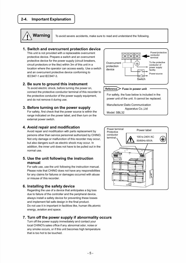
2-4. Important Explanation
To avoid severe accidents, make sure to read and understand the following.
1. Switch and overcurrent protection deviceThis unit is not provided with a replaceable overcurrentprotective device. Prepare a switch and an overcurrentprotective device for the power supply (circuit breakers,circuit protectors or the like) within 3m of this unit in alocation where the operator can access easily. Use a switchand an overcurrent protective device conforming toIEC947-1 and IEC947-3.
2. Be sure to ground this instrumentTo avoid electric shock, before turning the power on,
connect the protective conductor terminal of this recorder tothe protective conductor of the power supply equipment,and do not remove it during use.
3. Before turning on the power supplyFor safety, first check that the power source is within therange indicated on the power label, and then turn on theexternal power switch.
4. Avoid repair and modification Avoid repair and modification with parts replacement bypersons other than service personnel authorized by CHINO.
Not only damage or malfunction of this recorder may occur,but also dangers such as electric shock may occur. Inaddition, the inner unit does not have to be pulled out in thenormal use.
5. Use the unit following the instructionmanualFor safe use, use the unit following the instruction manual.Please note that CHINO does not have any responsibilitiesfor any claims for failures or damages occurred with abuseor misuse of this recorder.
6. Installing the safety deviceRegarding the use of a device that anticipates a big lossdue to failure of the controller and the peripheral device,always install a safety device for preventing these lossesand implement fail safe design in the final product.Do not use it in important in facilities like, human life,atomicenergy, aviation and space.
7. Turn off the power supply if abnormality occursTurn off the power supply immediately and contact yourlocal CHINO‟s sales office if any abnormal odor, noise or
any smoke occurs, or if this unit becomes high temperaturethat is too hot to be touched.
Overcurrentprotectiondevice
Switch
! Warning
For safety, the fuse below is included in thepower unit of the unit. It cannot be replaced.
Manufacturer:Daito Communication Apparatus Co.,Ltd
Model: SBL32
Reference Fuse in power unit
電源ラベル
100-240V AC
50/60Hz 65VA
Power terminalProtectiveconductor
terminal
Power label
100 to 240V AC
50/60Hz 65VA
To the protectiveconductor ofpower supplyfacility
Power/protectiveconductorterminal
Power source
7/23/2019 AH4000 Multi General INE-851B (1)
http://slidepdf.com/reader/full/ah4000-multi-general-ine-851b-1 9/121
- 6 -
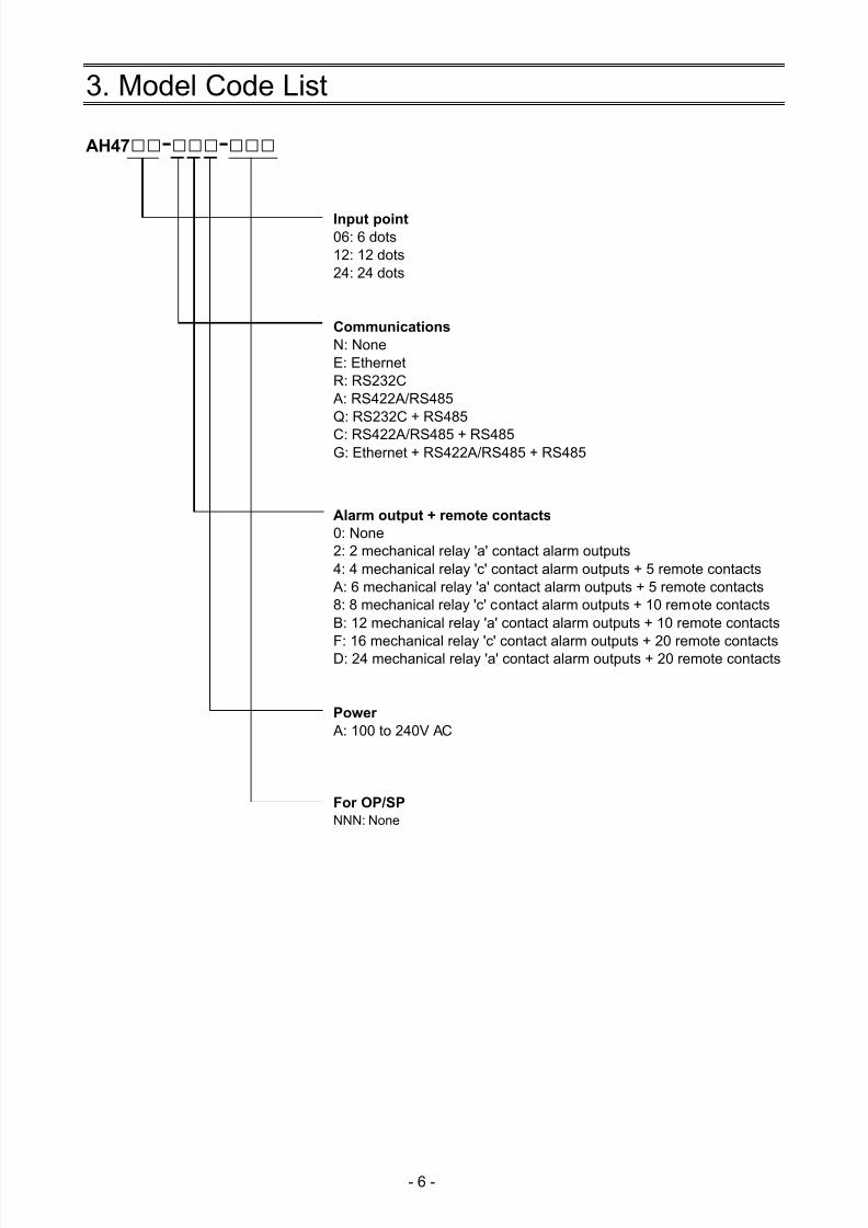
3. Model Code List
AH47--
Input point06: 6 dots12: 12 dots24: 24 dots
Communications
N: NoneE: EthernetR: RS232C A: RS422A/RS485Q: RS232C + RS485
C: RS422A/RS485 + RS485G: Ethernet + RS422A/RS485 + RS485
Alarm output + remote contacts
0: None2: 2 mechanical relay 'a' contact alarm outputs4: 4 mechanical relay 'c' contact alarm outputs + 5 remote contacts A: 6 mechanical relay 'a' contact alarm outputs + 5 remote contacts8: 8 mechanical relay 'c' contact alarm outputs + 10 remote contactsB: 12 mechanical relay 'a' contact alarm outputs + 10 remote contacts
F: 16 mechanical relay 'c' contact alarm outputs + 20 remote contactsD: 24 mechanical relay 'a' contact alarm outputs + 20 remote contacts
Power
A: 100 to 240V AC
For OP/SP
NNN: None
7/23/2019 AH4000 Multi General INE-851B (1)
http://slidepdf.com/reader/full/ah4000-multi-general-ine-851b-1 10/121
- 7 -
4. Mounting and Wiring
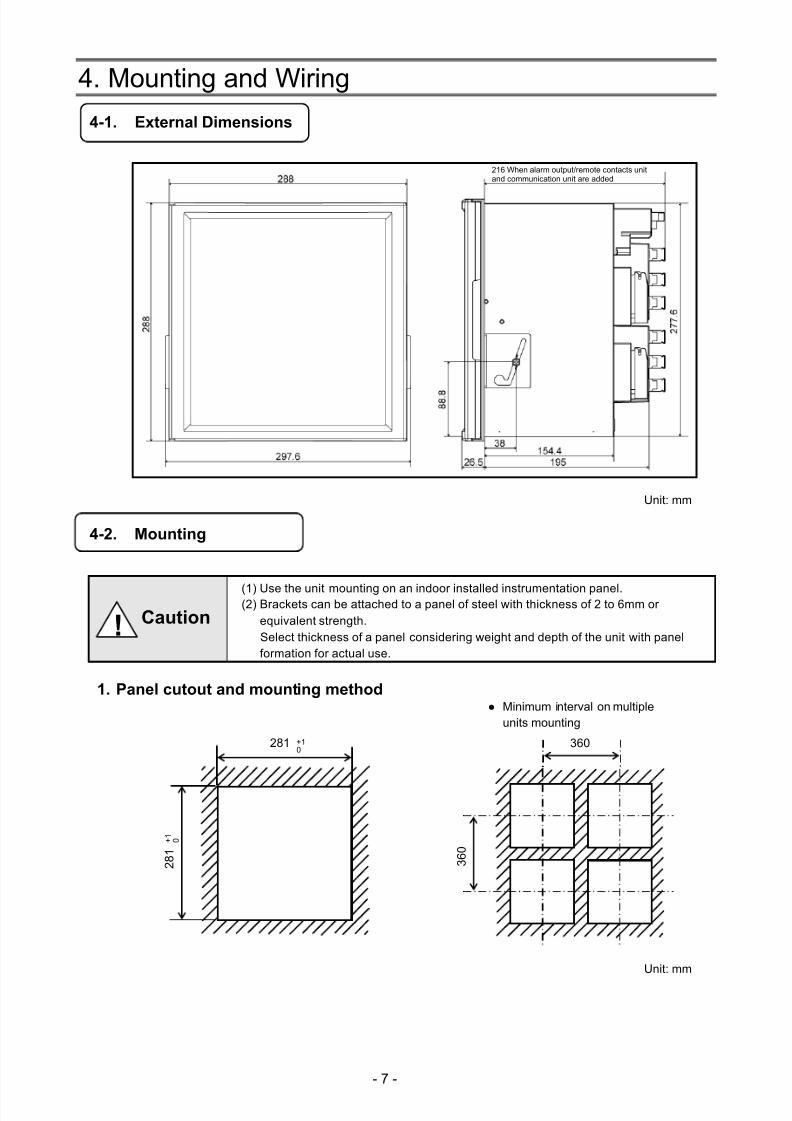
4-1. External Dimensions
Unit: mm
4-2. Mounting
(1) Use the unit mounting on an indoor installed instrumentation panel.(2) Brackets can be attached to a panel of steel with thickness of 2 to 6mm or
equivalent strength.Select thickness of a panel considering weight and depth of the unit with panelformation for actual use.
1. Panel cutout and mounting method
Unit: mm
2 8 1
+ 1
0
+10
281 360
3 6 0
Minimum interval on multipleunits mounting
! Caution
216 When alarm output/remote contacts unitand communication unit are added
7/23/2019 AH4000 Multi General INE-851B (1)
http://slidepdf.com/reader/full/ah4000-multi-general-ine-851b-1 11/121
- 8 -
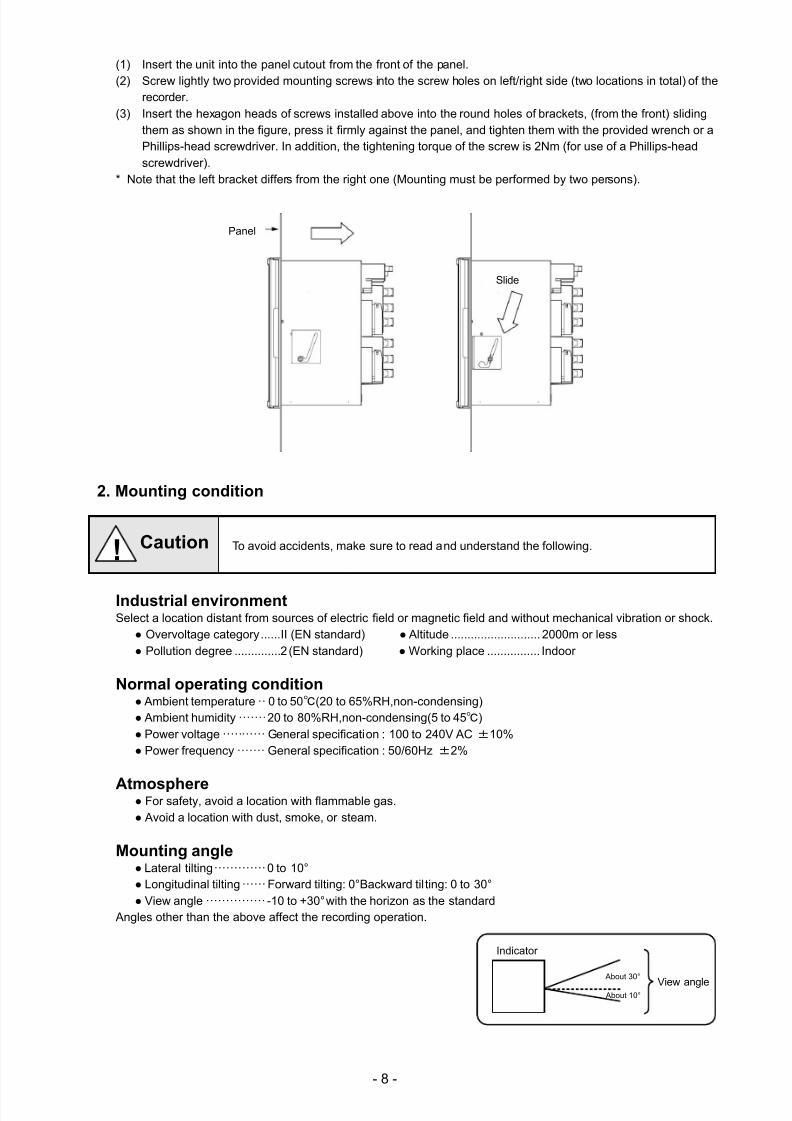
(1) Insert the unit into the panel cutout from the front of the panel.(2) Screw lightly two provided mounting screws into the screw holes on left/right side (two locations in total) of the
recorder.(3) Insert the hexagon heads of screws installed above into the round holes of brackets, (from the front) sliding
them as shown in the figure, press it firmly against the panel, and tighten them with the provided wrench or aPhillips-head screwdriver. In addition, the tightening torque of the screw is 2Nm (for use of a Phillips-headscrewdriver).
* Note that the left bracket differs from the right one (Mounting must be performed by two persons).
2. Mounting condition
To avoid accidents, make sure to read and understand the following.
Industrial environmentSelect a location distant from sources of electric field or magnetic field and without mechanical vibration or shock.
Overvoltage category ...... II (EN standard) Altitude ........................... 2000m or less Pollution degree .............. 2 (EN standard) Working place ................ Indoor
Normal operating condition Ambient temperature ·· 0 to 50(20 to 65%RH,non-condensing) Ambient humidity ······· 20 to 80%RH,non-condensing(5 to 45) Power voltage ··········· General specification : 100 to 240V AC ±10% Power frequency ······· General specification : 50/60Hz ±2%
Atmosphere For safety, avoid a location with flammable gas. Avoid a location with dust, smoke, or steam.
Mounting angle Lateral tilting ············· 0 to 10° Longitudinal tilting ······ Forward tilting: 0°Backward til ting: 0 to 30° View angle ··············· -10 to +30°with the horizon as the standard
Angles other than the above affect the recording operation.
! Caution
Indicator
View angle About 30°
About 10°
Panel
Slide
7/23/2019 AH4000 Multi General INE-851B (1)
http://slidepdf.com/reader/full/ah4000-multi-general-ine-851b-1 12/121
- 9 -
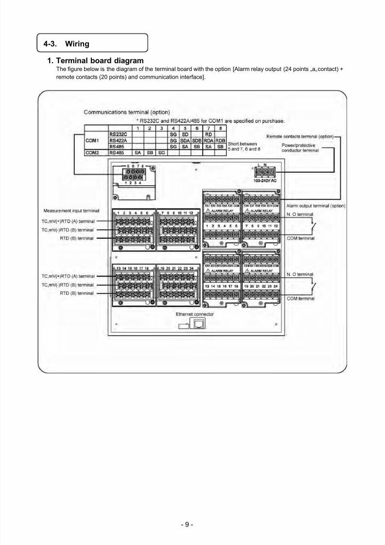
4-3. Wiring
1. Terminal board diagramThe figure below is the diagram of the terminal board with the option [Alarm relay output (24 points „a„ contact) +remote contacts (20 points) and communication interface].
7/23/2019 AH4000 Multi General INE-851B (1)
http://slidepdf.com/reader/full/ah4000-multi-general-ine-851b-1 13/121
- 10 -
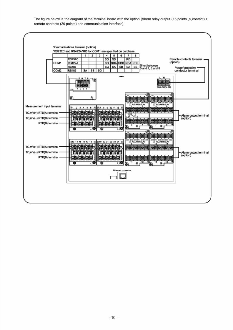
The figure below is the diagram of the terminal board with the option [Alarm relay output (16 points „c„ contact) +remote contacts (20 points) and communication interface].
7/23/2019 AH4000 Multi General INE-851B (1)
http://slidepdf.com/reader/full/ah4000-multi-general-ine-851b-1 14/121
- 11 -
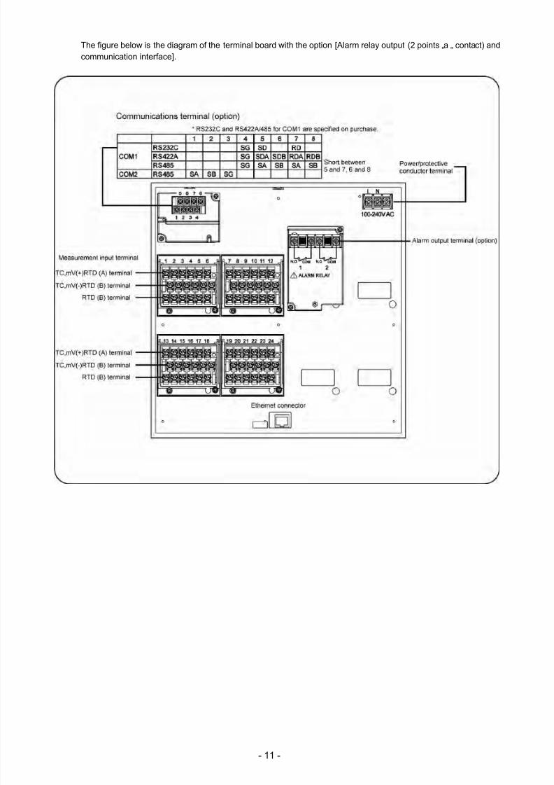
The figure below is the diagram of the terminal board with the option [Alarm relay output (2 points „a „ contact) andcommunication interface].
7/23/2019 AH4000 Multi General INE-851B (1)
http://slidepdf.com/reader/full/ah4000-multi-general-ine-851b-1 15/121
- 12 -
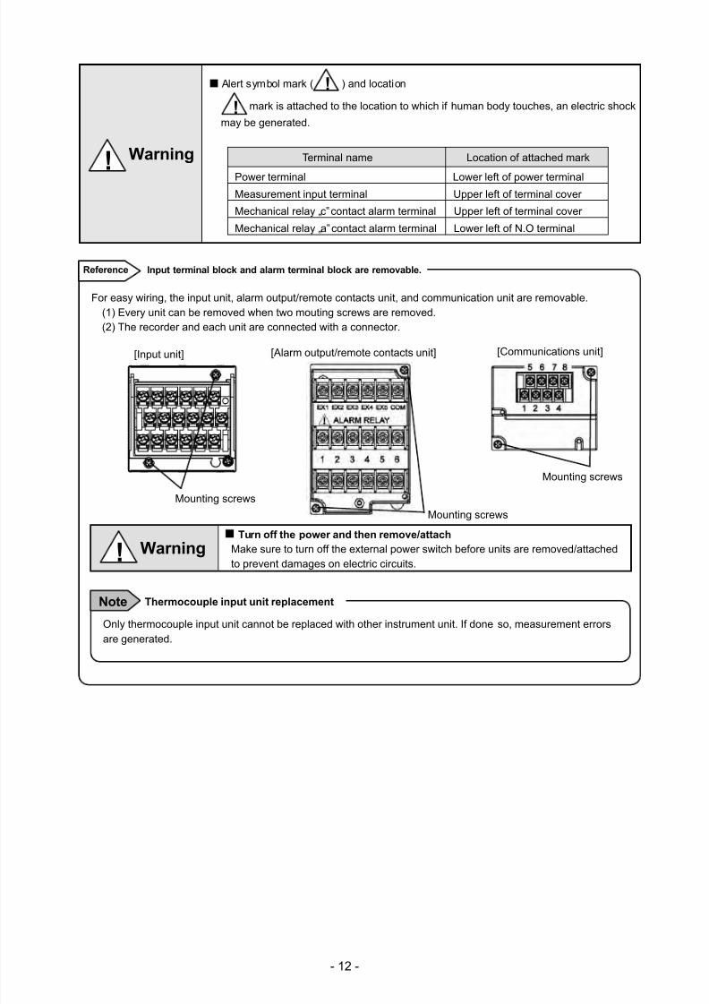
Alert symbol mark ( ) and location
mark is attached to the location to which if human body touches, an electric shock
may be generated.
Terminal name Location of attached mark
Power terminal Lower left of power terminalMeasurement input terminal Upper left of terminal cover
Mechanical relay „c‟ contact alarm terminal Upper left of terminal cover
Mechanical relay „a‟ contact alarm terminal Lower left of N.O terminal
!
!
! Warning
For easy wiring, the input unit, alarm output/remote contacts unit, and communication unit are removable.(1) Every unit can be removed when two mouting screws are removed.(2) The recorder and each unit are connected with a connector.
Turn off the power and then remove/attach
Make sure to turn off the external power switch before units are removed/attachedto prevent damages on electric circuits.
Input terminal block and alarm terminal block are removable.Reference
Only thermocouple input unit cannot be replaced with other instrument unit. If done so, measurement errorsare generated.
Note Thermocouple input unit replacement
! Warning
[Alarm output/remote contacts unit][Input unit] [Communications unit]
Mounting screws
Mounting screws
Mounting screws
7/23/2019 AH4000 Multi General INE-851B (1)
http://slidepdf.com/reader/full/ah4000-multi-general-ine-851b-1 16/121
- 13 -
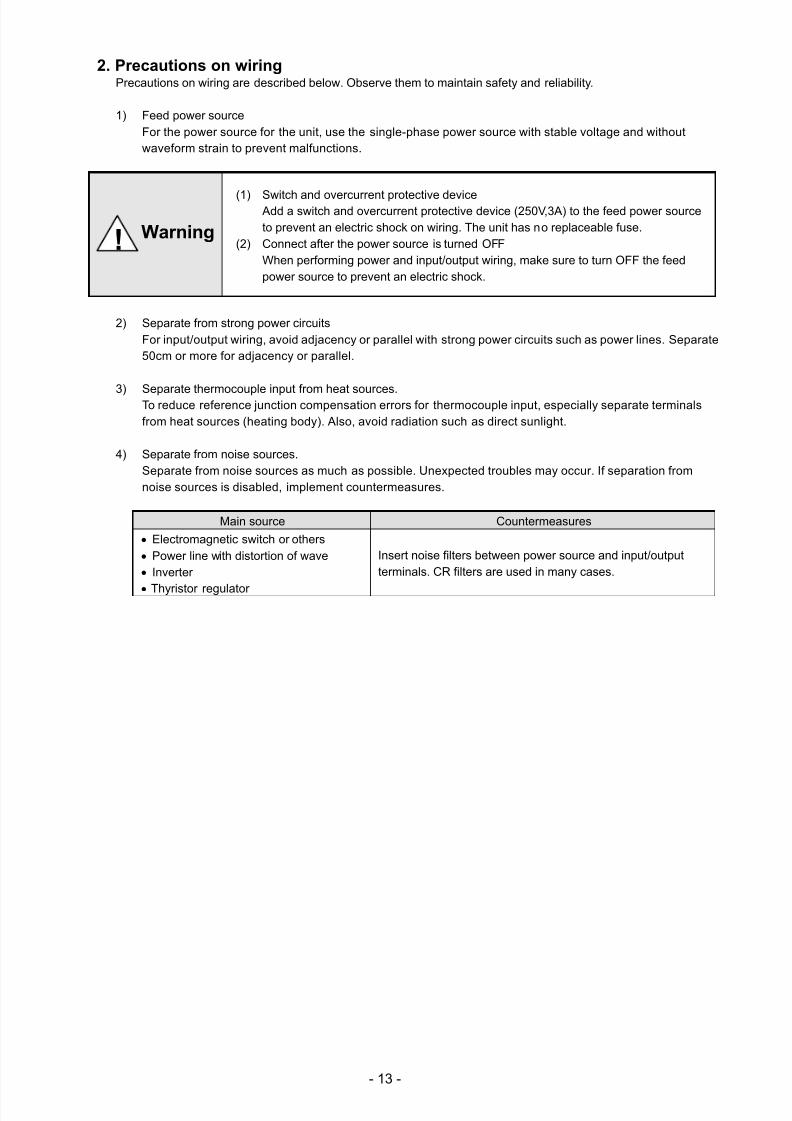
2. Precautions on wiring Precautions on wiring are described below. Observe them to maintain safety and reliability.
1) Feed power source
For the power source for the unit, use the single-phase power source with stable voltage and withoutwaveform strain to prevent malfunctions.
(1) Switch and overcurrent protective device Add a switch and overcurrent protective device (250V,3A) to the feed power sourceto prevent an electric shock on wiring. The unit has no replaceable fuse.
(2) Connect after the power source is turned OFFWhen performing power and input/output wiring, make sure to turn OFF the feedpower source to prevent an electric shock.
2) Separate from strong power circuitsFor input/output wiring, avoid adjacency or parallel with strong power circuits such as power lines. Separate50cm or more for adjacency or parallel.
3) Separate thermocouple input from heat sources.To reduce reference junction compensation errors for thermocouple input, especially separate terminalsfrom heat sources (heating body). Also, avoid radiation such as direct sunlight.
4) Separate from noise sources.Separate from noise sources as much as possible. Unexpected troubles may occur. If separation fromnoise sources is disabled, implement countermeasures.
Main source
Countermeasures
Electromagnetic switch or others
Power line with distortion of wave
Inverter
Thyristor regulator
Insert noise filters between power source and input/outputterminals. CR filters are used in many cases.
! Warning
7/23/2019 AH4000 Multi General INE-851B (1)
http://slidepdf.com/reader/full/ah4000-multi-general-ine-851b-1 17/121
- 14 -
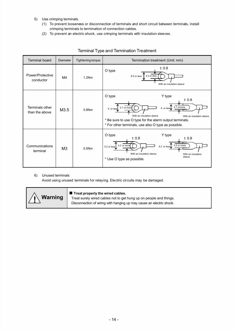
5) Use crimping terminals.(1) To prevent looseness or disconnection of terminals and short circuit between terminals, install
crimping terminals to termination of connection cables.(2) To prevent an electric shock, use crimping terminals with insulation sleeves.
Terminal Type and Termination Treatment
Terminal board Diameter Tightening torque Termination treatment (Unit: mm)
Power/Protectiveconductor
M4 1.2Nm
O type
Terminals otherthan the above
M3.5 0.8Nm
O type Y type
* Be sure to use O type for the alarm output terminals.* For other terminals, use also O type as possible.
Communicationsterminal
M3 0.5Nm
O type Y type
* Use O type as possible.
6) Unused terminals Avoid using unused terminals for relaying. Electric circuits may be damaged.
Treat properly the wired cables.
Treat surely wired cables not to get hung up on people and things.
Disconnection of wiring with hanging up may cause an electric shock.
8.5 or less 4.3 or less
t: 0.8
With an insulation sleeve
8 or less 3.7
or more
With an insulation sleeve
8 or less 3.7 ormore
t: 0.8
With an insulation sleeve
5.2
or less
3.2 or more
t: 0.8
With an insulationsleeve
5.2 or less
3.2
or more
With an insulation sleeve
t: 0.8
! Warning
7/23/2019 AH4000 Multi General INE-851B (1)
http://slidepdf.com/reader/full/ah4000-multi-general-ine-851b-1 18/121
- 15 -
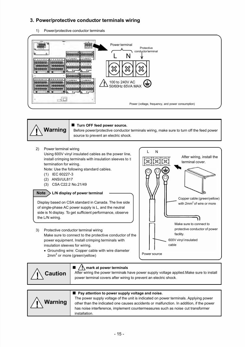
3. Power/protective conductor terminals wiring
1) Power/protective conductor terminals
Turn OFF feed power source.
Before power/protective conductor terminals wiring, make sure to turn off the feed powersource to prevent an electric shock.
2) Power terminal wiringUsing 600V vinyl insulated cables as the power line,install crimping terminals with insulation sleeves to thetermination for wiring.
Note: Use the following standard cables.
(1) IEC 60227-3
(2) ANSI/UL817(3) CSA C22.2 No.21/49
3) Protective conductor terminal wiringMake sure to connect to the protective conductor of thepower equipment. Install crimping terminals withinsulation sleeves for wiring.
Grounding wire: Copper cable with wire diameter2mm2 or more (green/yellow)
mark at power terminals
After wiring the power terminals have power supply voltage applied.Make sure to installpower terminal covers after wiring to prevent an electric shock.
Pay attention to power supply voltage and noise.
The power supply voltage of the unit is indicated on power terminals. Applying power
other than the indicated one causes accidents or malfunction. In addition, if the powerhas noise interference, implement countermeasures such as noise cut transformerinstallation.
!
! Warning
! Warning
! Caution
After wiring, install theterminal cover.
L N
Copper cable (green/yellow)
with 2mm2 of wire or more
Make sure to connect to
protective conductor of power
facility.
600V vinyl insulated
cable
Power source
Display based on CSA standard in Canada. The live sideof single-phase AC power supply is L, and the neutralside is N display. To get sufficient performance, observethe L/N wiring.
L/N display of power terminal Note
Power terminal
L N
Protectiveconductor terminal
100 to 240V AC50/60Hz 65VA MAX
Power (voltage, frequency, and power consumption)
!
7/23/2019 AH4000 Multi General INE-851B (1)
http://slidepdf.com/reader/full/ah4000-multi-general-ine-851b-1 19/121
- 16 -
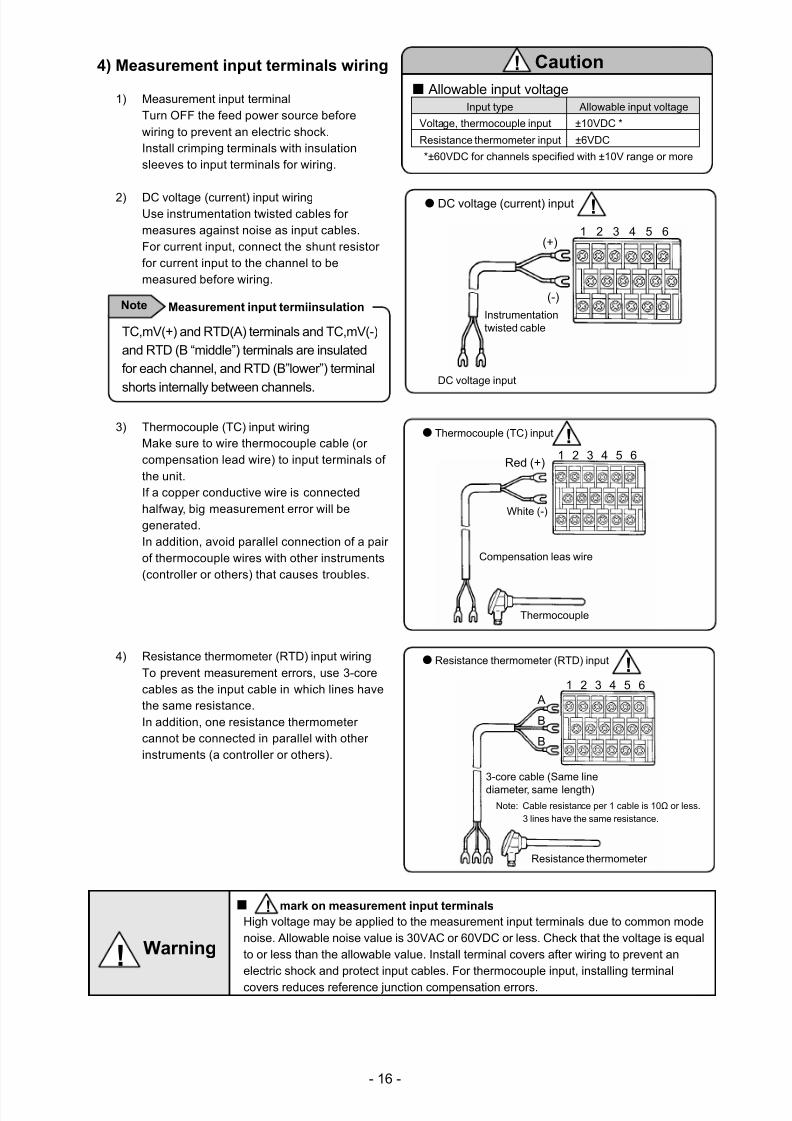
4) Measurement input terminals wiring
1) Measurement input terminal
Turn OFF the feed power source beforewiring to prevent an electric shock. Install crimping terminals with insulationsleeves to input terminals for wiring.
2) DC voltage (current) input wiring
Use instrumentation twisted cables formeasures against noise as input cables.For current input, connect the shunt resistorfor current input to the channel to bemeasured before wiring.
3) Thermocouple (TC) input wiring
Make sure to wire thermocouple cable (orcompensation lead wire) to input terminals ofthe unit.If a copper conductive wire is connectedhalfway, big measurement error will begenerated.In addition, avoid parallel connection of a pairof thermocouple wires with other instruments(controller or others) that causes troubles.
4) Resistance thermometer (RTD) input wiringTo prevent measurement errors, use 3-corecables as the input cable in which lines havethe same resistance.In addition, one resistance thermometercannot be connected in parallel with otherinstruments (a controller or others).
mark on measurement input terminals
High voltage may be applied to the measurement input terminals due to common modenoise. Allowable noise value is 30VAC or 60VDC or less. Check that the voltage is equalto or less than the allowable value. Install terminal covers after wiring to prevent anelectric shock and protect input cables. For thermocouple input, installing terminal
covers reduces reference junction compensation errors.
!
Instrumentationtwisted cable
DC voltage input
(+)
(-)
1 2 3 4 5 6
DC voltage (current) input !
Resistance thermometer (RTD) input
3-core cable (Same line
diameter, same length)Note: Cable resistance per 1 cable is 10Ω or less.
3 lines have the same resistance.
1 2 3 4 5 6
Resistance thermometer
A
B
B
!
TC,mV(+) and RTD(A) terminals and TC,mV(-)and RTD (B “middle”) terminals are insulatedfor each channel, and RTD (B”lower”) terminal
shorts internally between channels.
Measurement input termiinsulation Note
Allowable input voltageInput type Allowable input voltage
Voltage, thermocouple input ±10VDC *
Resistance thermometer input ±6VDC
*±60VDC for channels specified with ±10V range or more
Caution !
Compensation leas wire
Red (+)
White (-)
1 2 3 4 5 6
Thermocouple (TC) input !
Thermocouple
! Warning
7/23/2019 AH4000 Multi General INE-851B (1)
http://slidepdf.com/reader/full/ah4000-multi-general-ine-851b-1 20/121
- 17 -
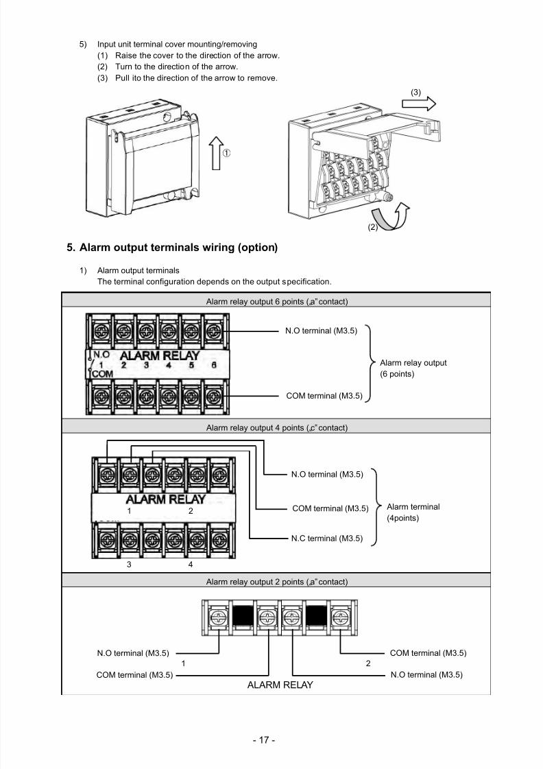
5) Input unit terminal cover mounting/removing
(1) Raise the cover to the direction of the arrow.(2) Turn to the direction of the arrow.(3) Pull ito the direction of the arrow to remove.
5. Alarm output terminals wiring (option)
1) Alarm output terminals
The terminal configuration depends on the output specification.
Alarm relay output 6 points („a‟ contact)
Alarm relay output 4 points („c‟ contact)
Alarm relay output 2 points („a‟ contact)
①
(2)
(3)
N.O terminal (M3.5)
COM terminal (M3.5)
Alarm relay output(6 points)
COM terminal (M3.5)
N.O terminal (M3.5)
COM terminal (M3.5)
N.O terminal (M3.5)
ALARM RELAY
1 2
N.O terminal (M3.5)
COM terminal (M3.5) Alarm terminal(4points)
1
2
3
4
N.C terminal (M3.5)
7/23/2019 AH4000 Multi General INE-851B (1)
http://slidepdf.com/reader/full/ah4000-multi-general-ine-851b-1 21/121
- 18 -
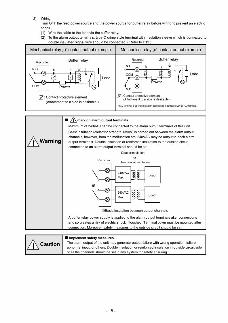
2) Wiring
Turn OFF the feed power source and the power source for buffer relay before wiring to prevent an electricshock.
(1) Wire the cable to the load via the buffer relay.(2) To the alarm output terminals, type O crimp style terminal with insulation sleeve which is connected to
double insulated signal wire should be connected. ( Refer to P13 )
Mechanical relay „a‟ contact output example Mechanical relay „c‟ contact output example
* N.C terminal is opened on alarm occurrence in opposite way to N.O terminal.
mark on alarm output terminals
Maximum of 240VAC can be connected to the alarm output terminals of this unit.
Basic insulation (dielectric strength 1390V) is carried out between the alarm output
channels, however, from the malfunction etc. 240VAC may be output to each alarm
output terminals. Double insulation or reinforced insulation to the outside circuit
connected to an alarm output terminal should be set.
A buffer relay power supply is applied to the alarm output terminals after connections
and so creates a risk of electric shock if touched. Terminal cover must be mounted after
connection. Moreover, safety measures to the outside circuit should be set.
Implement safety measures.
The alarm output of the unit may generate output failure with wrong operation, failure,abnormal input, or others. Double insulation or reinforced insulation in outside circuit sideof all the channels should be set in any system for safety ensuring.
!
! Caution
! Warning
: Contact protective element(Attachment to a side is desirable.)
N.O
COM
b a
Z Z
Buffer relayRecorder
Power
Load
: Contact protective element(Attachment to a side is desirable.)
Buffer relayRecorder
Power
LoadZ Z
N.C
N.O
COM
b a
240VAC
MaxLoad
240VAC
MaxLoad
※
Recorder
※Basic insulation between output channels
Double insulation
or
Reinforced insulation
7/23/2019 AH4000 Multi General INE-851B (1)
http://slidepdf.com/reader/full/ah4000-multi-general-ine-851b-1 22/121
- 19 -
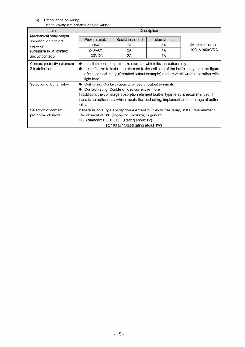
3) Precautions on wiringThe following are precautions on wiring.
Item Description
Mechanical relay outputspecification contactcapacity(Common to „a‟ contactand „c‟ contact)
Power supply Resistance load Inductive load
100VAC 2A 1A
240VAC 2A 1A
30VDC 2A 1A
Contact protective elementZ installation
Install the contact protective element which fits the buffer relay.
It is effective to install the element to the coil side of the buffer relay (see the figureof mechanical relay „a‟ contact output example) and prevents wrong operation withlight load.
Selection of buffer relay Coil rating: Contact capacity or less of output terminals
Contact rating: Double of load current or more
In addition, the coil surge absorption element built-in type relay is recommended. Ifthere is no buffer relay which meets the load rating, implement another stage of bufferrelay.
Selection of contactprotective element
If there is no surge absorption element built-in buffer relay, install this element.
The element of C/R (capacitor + resistor) is general.
<C/R standard> C: 0.01μF (Rating about1kv)
R: 100 to 150Ω (Rating about 1W)
(Minimum load) 100μA100mVDC
7/23/2019 AH4000 Multi General INE-851B (1)
http://slidepdf.com/reader/full/ah4000-multi-general-ine-851b-1 23/121
- 20 -
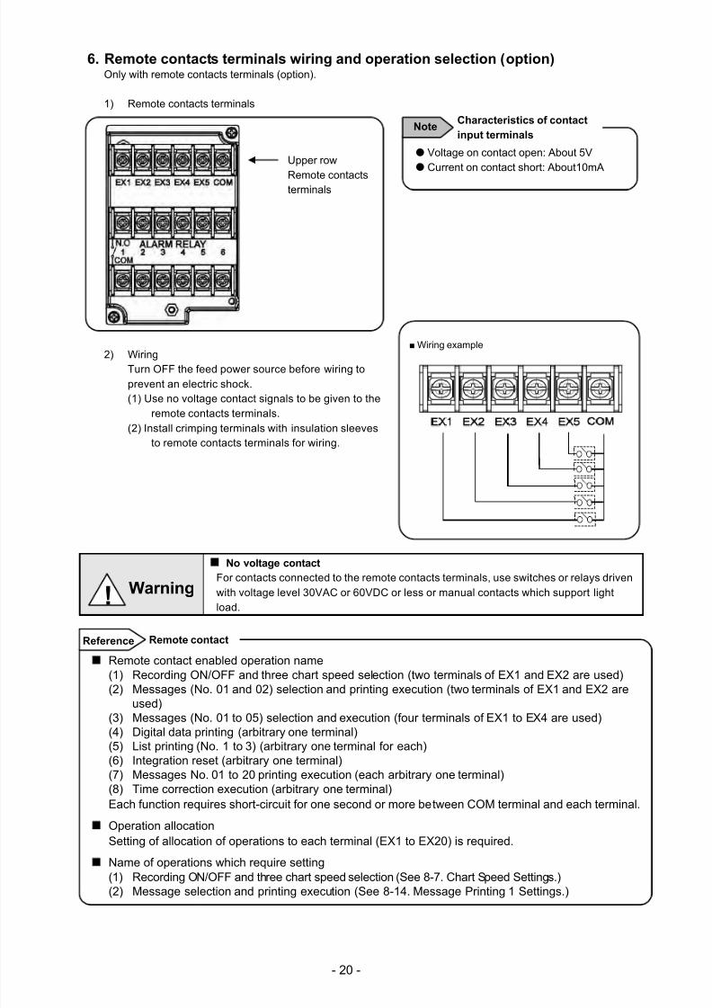
6. Remote contacts terminals wiring and operation selection (option) Only with remote contacts terminals (option).
1) Remote contacts terminals
2) Wiring
Turn OFF the feed power source before wiring toprevent an electric shock.(1) Use no voltage contact signals to be given to the
remote contacts terminals.(2) Install crimping terminals with insulation sleeves
to remote contacts terminals for wiring.
No voltage contact
For contacts connected to the remote contacts terminals, use switches or relays drivenwith voltage level 30VAC or 60VDC or less or manual contacts which support lightload.
Wiring example
Voltage on contact open: About 5V Current on contact short: About10mA
Note Characteristics of contact
input terminals
! Warning
Upper row
Remote contactsterminals
Remote contact enabled operation name(1) Recording ON/OFF and three chart speed selection (two terminals of EX1 and EX2 are used)(2) Messages (No. 01 and 02) selection and printing execution (two terminals of EX1 and EX2 are
used)(3) Messages (No. 01 to 05) selection and execution (four terminals of EX1 to EX4 are used)(4) Digital data printing (arbitrary one terminal)(5) List printing (No. 1 to 3) (arbitrary one terminal for each)(6) Integration reset (arbitrary one terminal)(7) Messages No. 01 to 20 printing execution (each arbitrary one terminal)(8) Time correction execution (arbitrary one terminal)Each function requires short-circuit for one second or more between COM terminal and each terminal.
Operation allocationSetting of allocation of operations to each terminal (EX1 to EX20) is required.
Name of operations which require setting
(1) Recording ON/OFF and three chart speed selection (See 8-7. Chart Speed Settings.)
(2) Message selection and printing execution (See 8-14. Message Printing 1 Settings.)
Remote contactReference
7/23/2019 AH4000 Multi General INE-851B (1)
http://slidepdf.com/reader/full/ah4000-multi-general-ine-851b-1 24/121
- 21 -
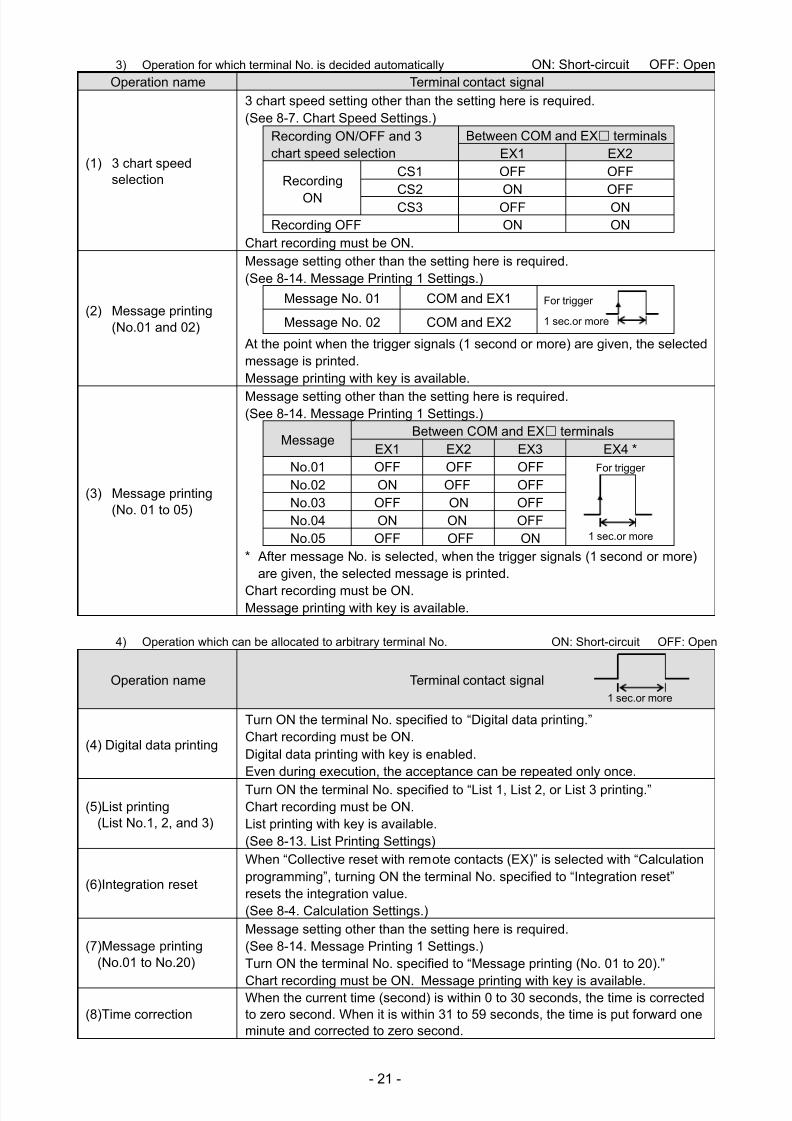
3) Operation for which terminal No. is decided automatically ON: Short-circuit OFF: Open
Operation name Terminal contact signal
(1) 3 chart speedselection
3 chart speed setting other than the setting here is required.
(See 8-7. Chart Speed Settings.) Recording ON/OFF and 3chart speed selection
Between COM and EX terminals
EX1 EX2
Recording
ON
CS1 OFF OFF
CS2 ON OFFCS3 OFF ONRecording OFF
ON ONChart recording must be ON.
(2) Message printing(No.01 and 02)
Message setting other than the setting here is required. (See 8-14. Message Printing 1 Settings.)
Message No. 01 COM and EX1
Message No. 02 COM and EX2
At the point when the trigger signals (1 second or more) are given, the selectedmessage is printed. Message printing with key is available.
(3) Message printing(No. 01 to 05)
Message setting other than the setting here is required.
(See 8-14. Message Printing 1 Settings.)
Message
Between COM and EX terminals
EX1 EX2 EX3 EX4 * No.01 OFF OFF OFF For trigger
No.02 ON OFF OFFNo.03 OFF ON OFFNo.04 ON ON OFFNo.05 OFF OFF ON
* After message No. is selected, when the trigger signals (1 second or more)are given, the selected message is printed.
Chart recording must be ON.
Message printing with key is available.
4) Operation which can be allocated to arbitrary terminal No. ON: Short-circuit OFF: Open
Operation name Terminal contact signal
(4) Digital data printing
Turn ON the terminal No. specified to “Digital data printing.” Chart recording must be ON.
Digital data printing with key is enabled. Even during execution, the acceptance can be repeated only once.
(5)List printing(List No.1, 2, and 3)
Turn ON the terminal No. specified to “List 1, List 2, or List 3 printing.”
Chart recording must be ON. List printing with key is available. (See 8-13. List Printing Settings)
(6)Integration reset
When “Collective reset with remote contacts (EX)” is selected with “Calculationprogramming”, turning ON the terminal No. specified to “Integration reset”resets the integration value. (See 8-4. Calculation Settings.)
(7)Message printing(No.01 to No.20)
Message setting other than the setting here is required. (See 8-14. Message Printing 1 Settings.) Turn ON the terminal No. specified to “Message printing (No. 01 to 20).”
Chart recording must be ON.
Message printing with key is available.
(8)Time correctionWhen the current time (second) is within 0 to 30 seconds, the time is correctedto zero second. When it is within 31 to 59 seconds, the time is put forward oneminute and corrected to zero second.
1 sec.or more
For trigger
1 sec.or more
1 sec.or more
7/23/2019 AH4000 Multi General INE-851B (1)
http://slidepdf.com/reader/full/ah4000-multi-general-ine-851b-1 25/121
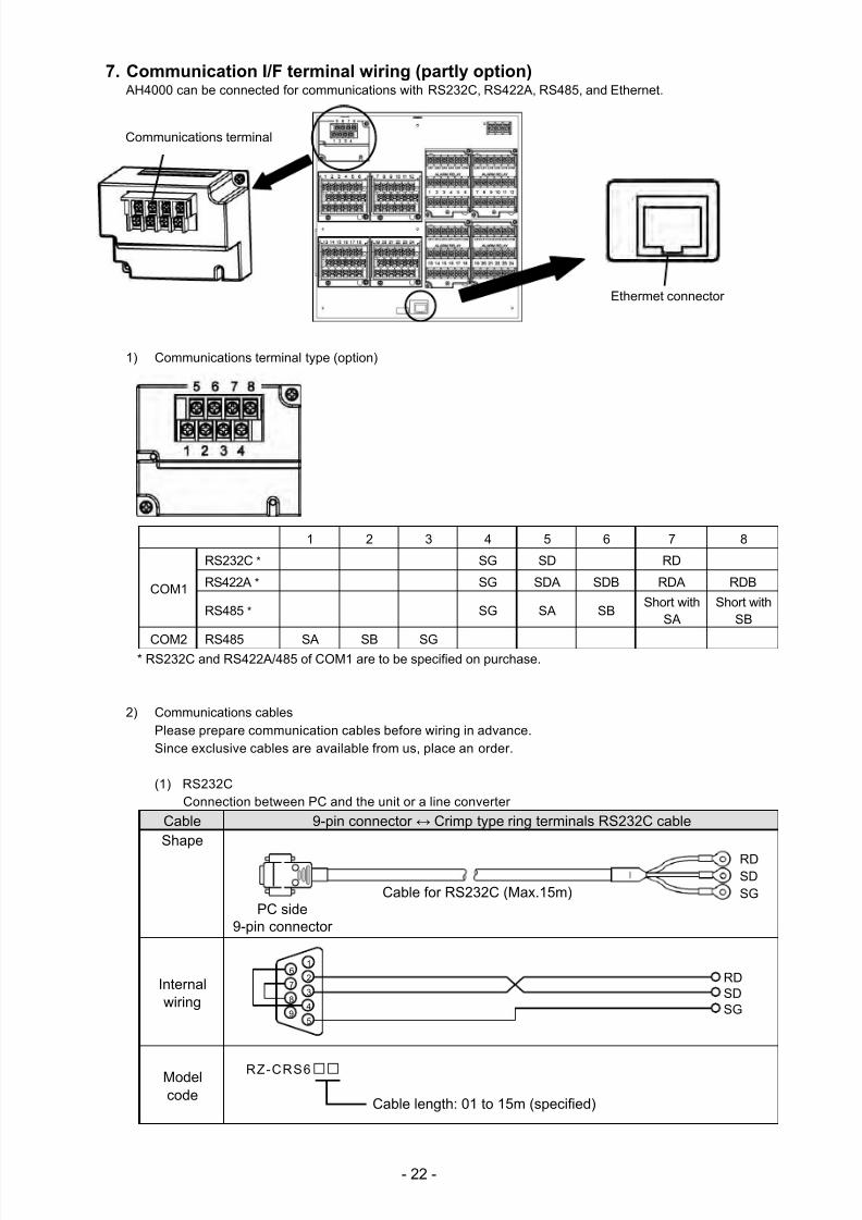
- 22 -
7. Communication I/F terminal wiring (partly option) AH4000 can be connected for communications with RS232C, RS422A, RS485, and Ethernet.
1) Communications terminal type (option)
1 2 3 4 5 6 7 8
COM1
RS232C * SG SD RD
RS422A * SG SDA SDB RDA RDB
RS485 * SG SA SBShort with
SAShort with
SB
COM2 RS485 SA SB SG* RS232C and RS422A/485 of COM1 are to be specified on purchase.
2) Communications cables
Please prepare communication cables before wiring in advance.Since exclusive cables are available from us, place an order.
(1) RS232CConnection between PC and the unit or a line converter
Cable 9-pin connector ↔ Crimp type ring terminals RS232C cable
Shape
Internalwiring
Modelcode
RZ-CRS6
Cable length: 01 to 15m (specified)
Ethermet connector
C. terminals
RDSDSG
PC side9-pin connector
Cable for RS232C (Max.15m)
RDSDSG
1
2
3
4
5
6
7
8
9
Communications terminal
7/23/2019 AH4000 Multi General INE-851B (1)
http://slidepdf.com/reader/full/ah4000-multi-general-ine-851b-1 26/121
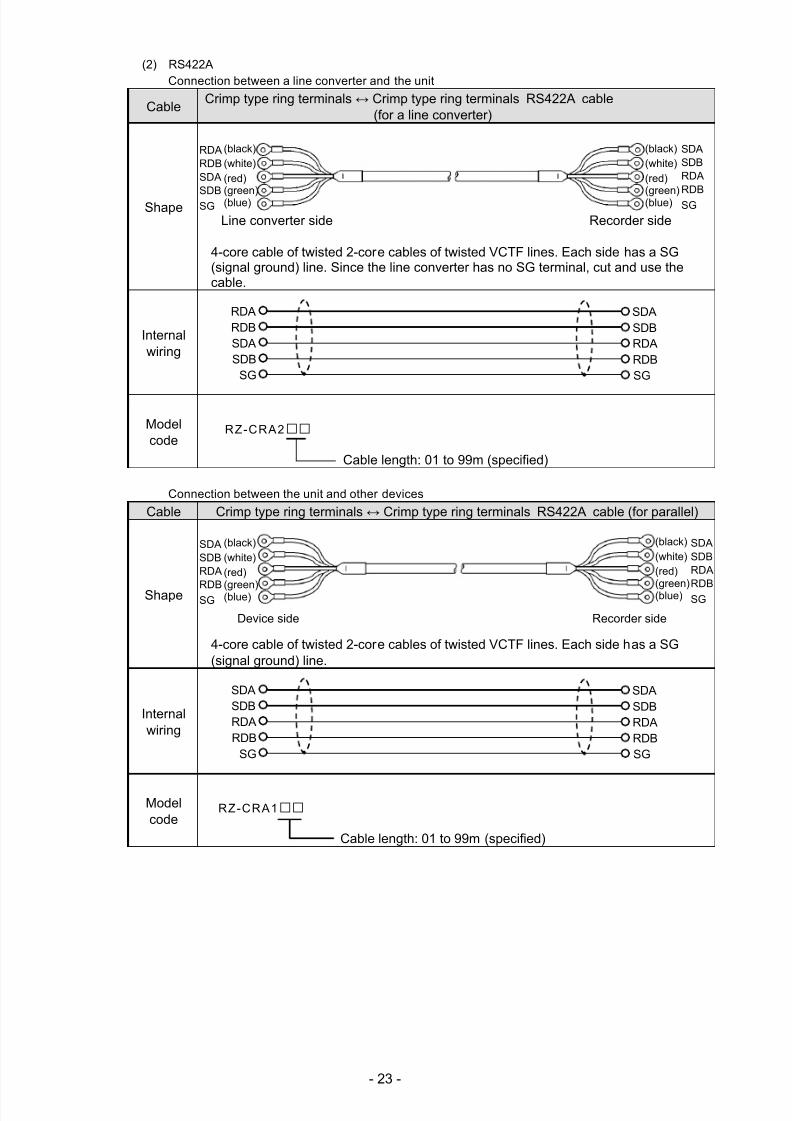
- 23 -
(2) RS422AConnection between a line converter and the unit
Cable Crimp type ring terminals ↔ Crimp type ring terminals RS422A cable
(for a line converter)
Shape
4-core cable of twisted 2-core cables of twisted VCTF lines. Each side has a SG(signal ground) line. Since the line converter has no SG terminal, cut and use thecable.
Internalwiring
Modelcode
RZ-CRA2
Cable length: 01 to 99m (specified)
Connection between the unit and other devices
Cable
Crimp type ring terminals ↔ Crimp type ring terminals
RS422A
cable (for parallel)
Shape
4-core cable of twisted 2-core cables of twisted VCTF lines. Each side has a SG(signal ground) line.
Internalwiring
Modelcode
RZ-CRA1
Cable length: 01 to 99m (specified)
Line converter side Recorder side
RDBRDA
SDASDB
SG
SDBSDA
RDARDBSG
Device side Recorder side
SDBSDA
RDARDB
SG
SDBSDA
RDARDBSG
(black)(white)(red)(green)(blue)
RDARDBSDA
SDBSG
SDASDBRDARDB
SG
(black)(white)(red)(green)(blue)
(black)(white)(red)
(green)(blue)
SDASDBRDA
RDBSG
SDASDBRDA
RDBSG
(black)(white)(red)(green)(blue)
7/23/2019 AH4000 Multi General INE-851B (1)
http://slidepdf.com/reader/full/ah4000-multi-general-ine-851b-1 27/121
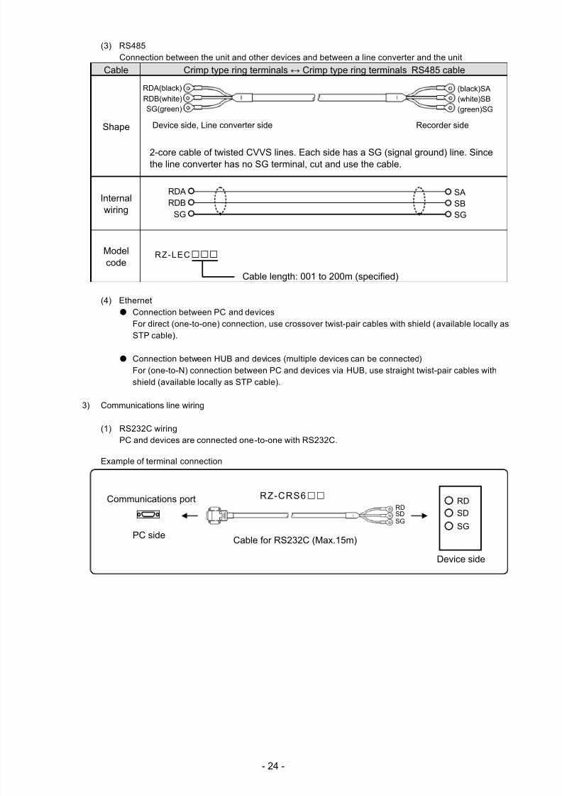
- 24 -
(3) RS485Connection between the unit and other devices and between a line converter and the unit
Cable Crimp type ring terminals ↔ Crimp type ring terminals RS485 cable
Shape
2-core cable of twisted CVVS lines. Each side has a SG (signal ground) line. Sincethe line converter has no SG terminal, cut and use the cable.
Internalwiring
Modelcode
RZ-LEC
Cable length: 001 to 200m (specified)
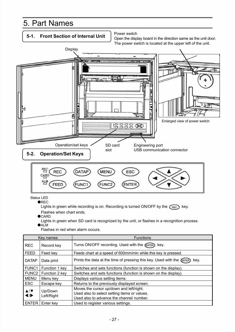
(4) Ethernet Connection between PC and devices
For direct (one-to-one) connection, use crossover twist-pair cables with shield (available locally asSTP cable).
Connection between HUB and devices (multiple devices can be connected)For (one-to-N) connection between PC and devices via HUB, use straight twist-pair cables withshield (available locally as STP cable).
3) Communications line wiring
(1) RS232C wiringPC and devices are connected one-to-one with RS232C.
Example of terminal connection
RDA(black)RDB(white)SG(green)
(black)SA(white)SB(green)SG
Device side, Line converter side Recorder side
RDARDB
SG
SASBSG
SD
RD
SG
Cable for RS232C (Max.15m)
Device side
RDSDSG
RZ-CRS6 Communications port
PC side
7/23/2019 AH4000 Multi General INE-851B (1)
http://slidepdf.com/reader/full/ah4000-multi-general-ine-851b-1 28/121
- 25 -
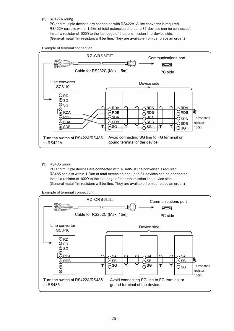
(2) RS422A wiringPC and multiple devices are connected with RS422A. A line converter is required.RS422A cable is within 1.2km of total extension and up to 31 devices can be connected.Install a resistor of 100Ω to the last edge of the transmission line device side.(General metal film resistors will be fine. They are available from us, place an order.)
Example of terminal connection
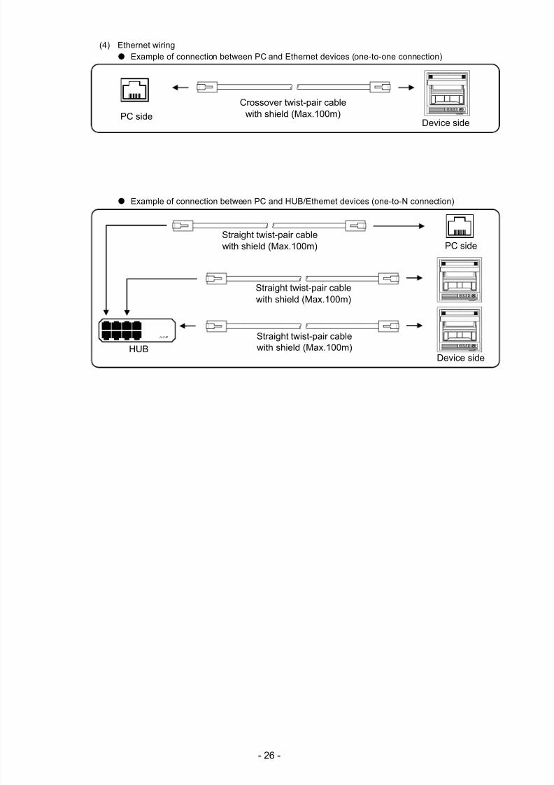
(3) RS485 wiringPC and multiple devices are connected with RS485. A line converter is required.
RS485 cable is within 1.2km of total extension and up to 31 devices can be connected.Install a resistor of 100Ω to the last edge of the transmission line device side.(General metal film resistors will be fine. They are available from us, place an order.)
Example of terminal connection
Turn the switch of RS422A/RS485to RS422A.
Avoid connecting SG line to FG terminal orgound terminal of the device.
RDB
RDA
SDASDB
SG
Termination
resistor
100Ω
Device sideLine converterSC8-10
RDB
RDA
SDASDB
SDRD
SG
1
2
3
4
56
7
8
Cable for RS232C (Max. 15m)
RZ-CRS6
Communications port
PC side
SDRD
SG
RDB
RDA
SDASDB
SG
RDB
RDA
SDASDB
SG
SASB SG
RDB RDA
SDRD
SG
1
2
3
4
5
6
7
8
Turn the switch of RS422A/RS485to RS485.
Avoid connecting SG line to FG terminal orgound terminal of the device.
Termination
resistor
100Ω
Device sideLine converter
SC8-10
Cable for RS232C (Max. 15m)
RZ-CRS6 Communications port
PC side
SDRD
SG
SASB SG
SASB
SG
7/23/2019 AH4000 Multi General INE-851B (1)
http://slidepdf.com/reader/full/ah4000-multi-general-ine-851b-1 29/121
- 26 -
(4) Ethernet wiring Example of connection between PC and Ethernet devices (one-to-one connection)
Example of connection between PC and HUB/Ethernet devices (one-to-N connection)
Crossover twist-pair cablewith shield (Max.100m)
Device sidePC side
Device sideHUB
Straight twist-pair cablewith shield (Max.100m)
PC side
HUB
Straight twist-pair cablewith shield (Max.100m)
Straight twist-pair cablewith shield (Max.100m)
7/23/2019 AH4000 Multi General INE-851B (1)
http://slidepdf.com/reader/full/ah4000-multi-general-ine-851b-1 30/121
- 27 -
5. Part Names
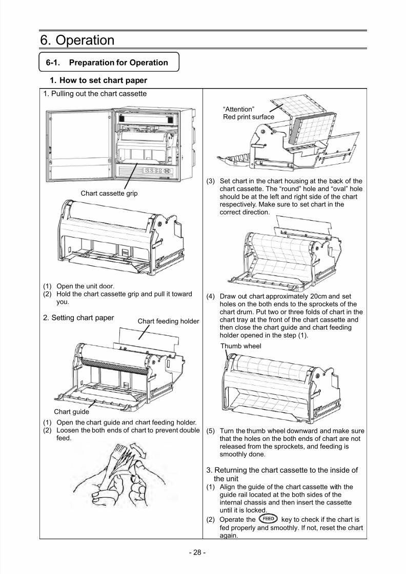
5-1. Front Section of Internal Unit
5-2. Operation/Set Keys
Status LEDREC
Lights in green while recording is on. Recording is turned ON/OFF by the key.
Flashes when chart ends.CARD
Lights in green when SD card is recognized by the unit, or flashes in a recognition process. ALM
Flashes in red when alarm occurs.
Key names Functions
REC Record key Turns ON/OFF recording. Used with the key.
FEED Feed key Feeds chart at a speed of 600mm/min while this key is pressed.
DATAP Data print Prints the data at the time of pressing this key. Used with the key.
FUNC1 Function 1 key Switches and sets functions (function is shown on the display).FUNC2 Function 2 key Switches and sets functions (function is shown on the display).MENU Menu key Displays various setting items.ESC Escape key Returns to the previously displayed screen.
/
/
Up/DownLeft/Right
Moves the cursor up/down and left/right.Used also to select setting items or values.Used also to advance the channel number.
ENTER Enter key Used to register various settings.
Enlarged view of power switch
Power switchOpen the display board in the direction same as the unit door.The power switch is located at the upper left of the unit.
Display
Engineering portUSB communication connector
SD cardslot
Operation/set keys
7/23/2019 AH4000 Multi General INE-851B (1)
http://slidepdf.com/reader/full/ah4000-multi-general-ine-851b-1 31/121
- 28 -
6. Operation
6-1. Preparation for Operation
1. How to set chart paper
1. Pulling out the chart cassette
(1) Open the unit door.(2) Hold the chart cassette grip and pull it toward
you.
2. Setting chart paper
(1) Open the chart guide and chart feeding holder.(2) Loosen the both ends of chart to prevent double
feed.
(3) Set chart in the chart housing at the back of thechart cassette. The “round” hole and “oval” holeshould be at the left and right side of the chartrespectively. Make sure to set chart in thecorrect direction.
(4) Draw out chart approximately 20cm and setholes on the both ends to the sprockets of thechart drum. Put two or three folds of chart in thechart tray at the front of the chart cassette andthen close the chart guide and chart feedingholder opened in the step (1).
(5) Turn the thumb wheel downward and make surethat the holes on the both ends of chart are notreleased from the sprockets, and feeding issmoothly done.
3. Returning the chart cassette to the inside ofthe unit
(1) Align the guide of the chart cassette with theguide rail located at the both sides of the
internal chassis and then insert the cassetteuntil it is locked.(2) Operate the key to check if the chart is
fed properly and smoothly. If not, reset the chartagain.
Chart feeding holder
Chart guide
Thumb wheel
“Attention”Red print surface
Chart cassette grip
7/23/2019 AH4000 Multi General INE-851B (1)
http://slidepdf.com/reader/full/ah4000-multi-general-ine-851b-1 32/121
- 29 -
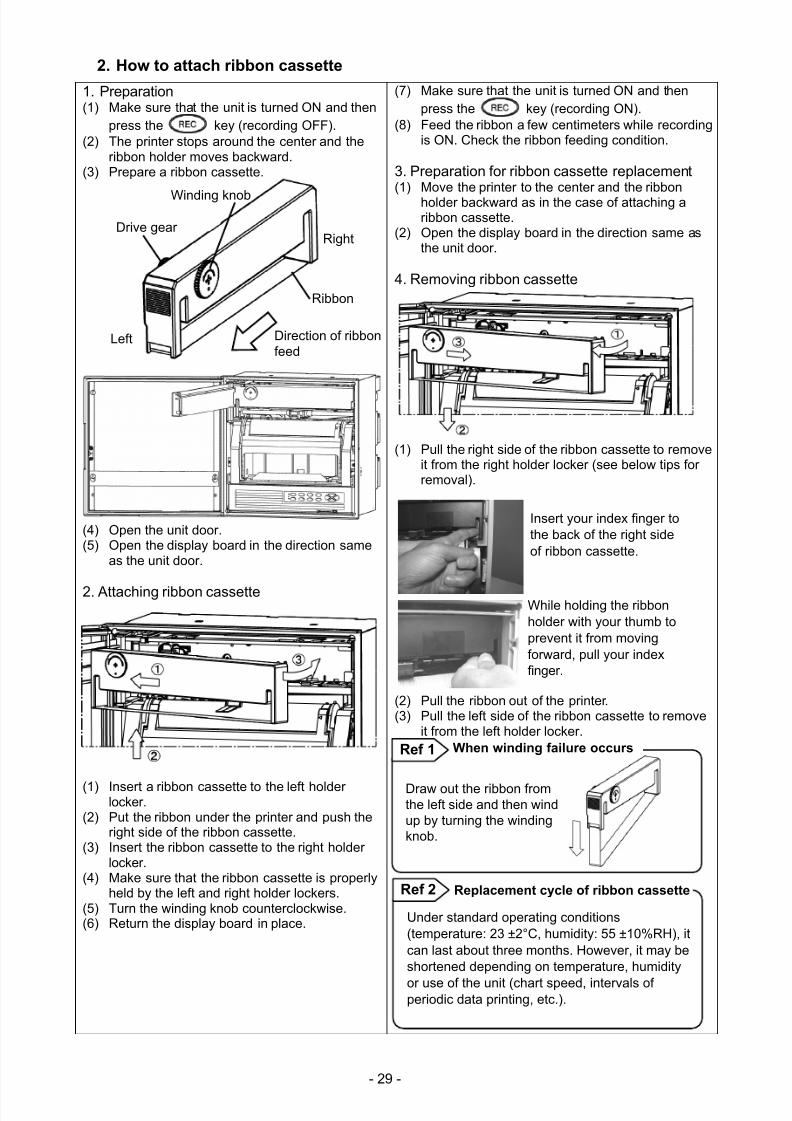
2. How to attach ribbon cassette
1. Preparation(1) Make sure that the unit is turned ON and then
press the key (recording OFF).(2) The printer stops around the center and the
ribbon holder moves backward.(3) Prepare a ribbon cassette.
(4) Open the unit door.(5) Open the display board in the direction same
as the unit door.
2. Attaching ribbon cassette
(1) Insert a ribbon cassette to the left holderlocker.
(2) Put the ribbon under the printer and push theright side of the ribbon cassette.
(3) Insert the ribbon cassette to the right holderlocker.
(4) Make sure that the ribbon cassette is properlyheld by the left and right holder lockers.
(5) Turn the winding knob counterclockwise.(6) Return the display board in place.
(7) Make sure that the unit is turned ON and thenpress the key (recording ON).
(8) Feed the ribbon a few centimeters while recordingis ON. Check the ribbon feeding condition.
3. Preparation for ribbon cassette replacement(1) Move the printer to the center and the ribbon
holder backward as in the case of attaching aribbon cassette.
(2) Open the display board in the direction same asthe unit door.
4. Removing ribbon cassette
(1) Pull the right side of the ribbon cassette to removeit from the right holder locker (see below tips forremoval).
(2) Pull the ribbon out of the printer.(3) Pull the left side of the ribbon cassette to remove
it from the left holder locker.
Drive gear
Ribbon
Winding knob
Direction of ribbonfeed
Right
Left
Under standard operating conditions(temperature: 23 ±2°C, humidity: 55 ±10%RH), itcan last about three months. However, it may beshortened depending on temperature, humidity
or use of the unit (chart speed, intervals ofperiodic data printing, etc.).
Replacement cycle of ribbon cassetteRef 2
Draw out the ribbon fromthe left side and then windup by turning the windingknob.
When winding failure occursRef 1
Insert your index finger tothe back of the right sideof ribbon cassette.
While holding the ribbonholder with your thumb toprevent it from movingforward, pull your indexfinger.
7/23/2019 AH4000 Multi General INE-851B (1)
http://slidepdf.com/reader/full/ah4000-multi-general-ine-851b-1 33/121
- 30 -
6-2. Basic Operation
1. Power onTurn the power switch to ON.Data will be shown on the display after about 10 seconds. After detecting the initial position, the printer prints the date and time and then feeds chart about 5mm.
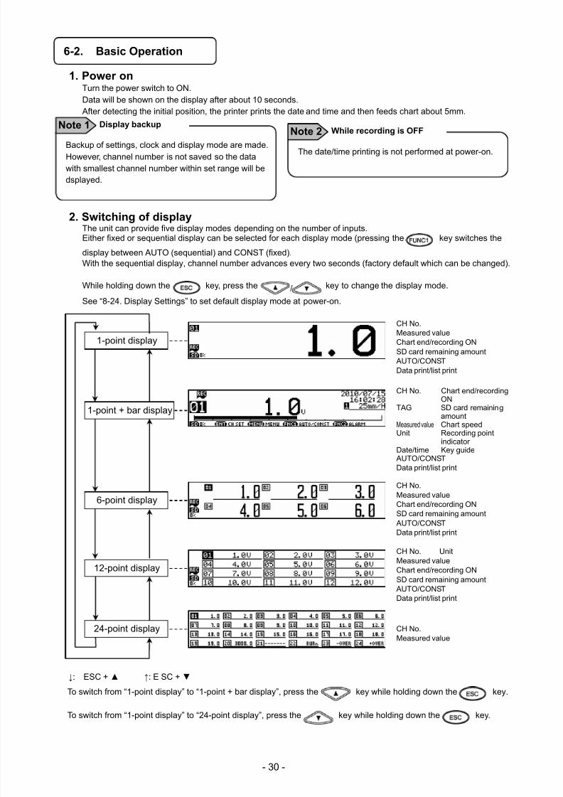
2. Switching of displayThe unit can provide five display modes depending on the number of inputs.Either fixed or sequential display can be selected for each display mode (pressing the key switches the
display between AUTO (sequential) and CONST (fixed).With the sequential display, channel number advances every two seconds (factory default which can be changed).
While holding down the key, press the / key to change the display mode.
See “8-24. Display Settings” to set default display mode at power-on.
CH No.Measured valueChart end/recording ONSD card remaining amount AUTO/CONSTData print/list print
CH No. Chart end/recordingON
TAG SD card remaining
amountMeasured value Chart speedUnit Recording point
indicatorDate/time Key guide AUTO/CONSTData print/list print
CH No.Measured value Chart end/recording ON
SD card remaining amount AUTO/CONSTData print/list print
CH No. Unit
Measured value
Chart end/recording ON SD card remaining amount AUTO/CONSTData print/list print
CH No. Measured value
↓: ESC + ↑: E SC +
To switch from “1-point display” to “1-point + bar display”, press the key while holding down the key.
To switch from “1-point display” to “24-point display”, press the key while holding down the key.
The date/time printing is not performed at power-on.
Note 2 While recording is OFF
Backup of settings, clock and display mode are made.However, channel number is not saved so the datawith smallest channel number within set range will bedsplayed.
Display backupNote 1
12-point display
6-point display
1-point display
24-point display
1-point + bar display
7/23/2019 AH4000 Multi General INE-851B (1)
http://slidepdf.com/reader/full/ah4000-multi-general-ine-851b-1 34/121
- 31 -
3. Chart recording operation
Recording ON
Recording OFF
* Any of the above settings can be cancelled by pressing the key.
(The setting is cancelled also after around 10 seconds without key operation.)
1) Turning ON/OFF chart recording
Recording can be turned ON/OFF by pressing the key → key.While recording is ON, the “REC” status LED lights up.Recording is not performed while it is OFF, but reading inputs, updating data and calculating alarms areperformed. Data printing, list printing and message printing are unavailable.
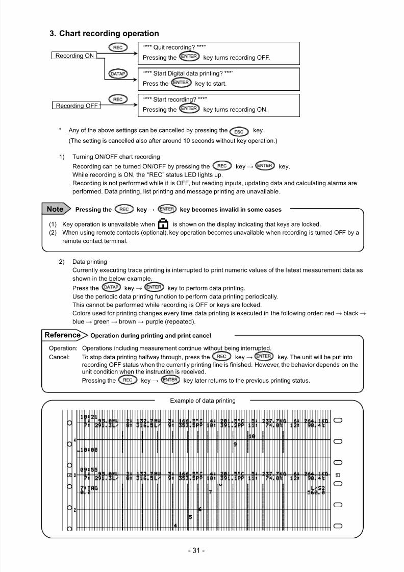
2) Data printingCurrently executing trace printing is interrupted to print numeric values of the latest measurement data asshown in the below example.
Press the key → key to perform data printing.Use the periodic data printing function to perform data printing periodically.This cannot be performed while recording is OFF or keys are locked.Colors used for printing changes every time data printing is executed in the following order: red → black →blue → green → brown → purple (repeated).
Example of data printing
“*** Quit recording? ***”
Pressing the key turns recording OFF.
“*** Start Digital data printing? ***”
Press the key to start.
“*** Start recording? ***”Pressing the key turns recording ON.
(1) Key operation is unavailable when is shown on the display indicating that keys are locked.(2) When using remote contacts (optional), key operation becomes unavailable when recording is turned OFF by a
remote contact terminal.
Pressing the key → key becomes invalid in some casesNote
Operation: Operations including measurement continue without being interrupted.
Cancel: To stop data printing halfway through, press the key → key. The unit will be put intorecording OFF status when the currently printing line is finished. However, the behavior depends on theunit condition when the instruction is received.
Pressing the key → key later returns to the previous printing status.
Operation during printing and print cancelReference
7/23/2019 AH4000 Multi General INE-851B (1)
http://slidepdf.com/reader/full/ah4000-multi-general-ine-851b-1 35/121
- 32 -
3) Chart feed Chart can be fed using the key.
While the key is pressed, chart is fed at a speed of 600mm/min. When fast-feeding chart,recording (dot-printing) is stopped.Feed chart when a measurement target or measurement condition is changed.
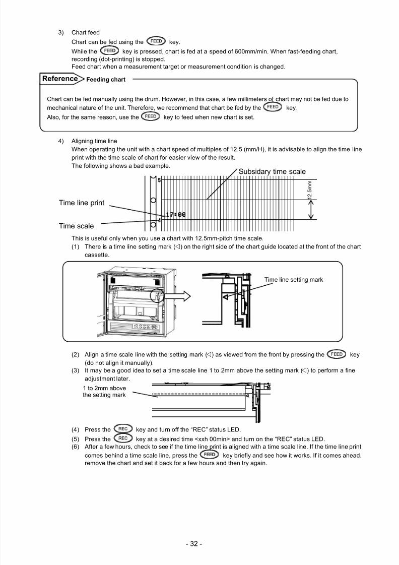
4) Aligning time lineWhen operating the unit with a chart speed of multiples of 12.5 (mm/H), it is advisable to align the time lineprint with the time scale of chart for easier view of the result.The following shows a bad example.
Time line print
Time scale
This is useful only when you use a chart with 12.5mm-pitch time scale.(1) There is a time line setting mark () on the right side of the chart guide located at the front of the chart
cassette.
Time line setting mark
(2) Align a time scale line with the setting mark () as viewed from the front by pressing the key(do not align it manually).
(3) It may be a good idea to set a time scale line 1 to 2mm above the setting mark () to perform a fineadjustment later.
(4) Press the key and turn off the “REC” status LED.
(5) Press the key at a desired time <xxh 00min> and turn on the “REC” status LED.(6) After a few hours, check to see if the time line print is aligned with a time scale line. If the time line print
comes behind a time scale line, press the key briefly and see how it works. If it comes ahead,remove the chart and set it back for a few hours and then try again.
Chart can be fed manually using the drum. However, in this case, a few millimeters of chart may not be fed due tomechanical nature of the unit. Therefore, we recommend that chart be fed by the key.
Also, for the same reason, use the key to feed when new chart is set.
Feeding chart
1 to 2mm above
the setting mark
1
2 . 5
m m
Subsidary time scale
Reference
7/23/2019 AH4000 Multi General INE-851B (1)
http://slidepdf.com/reader/full/ah4000-multi-general-ine-851b-1 36/121
- 33 -
6-3. Operation
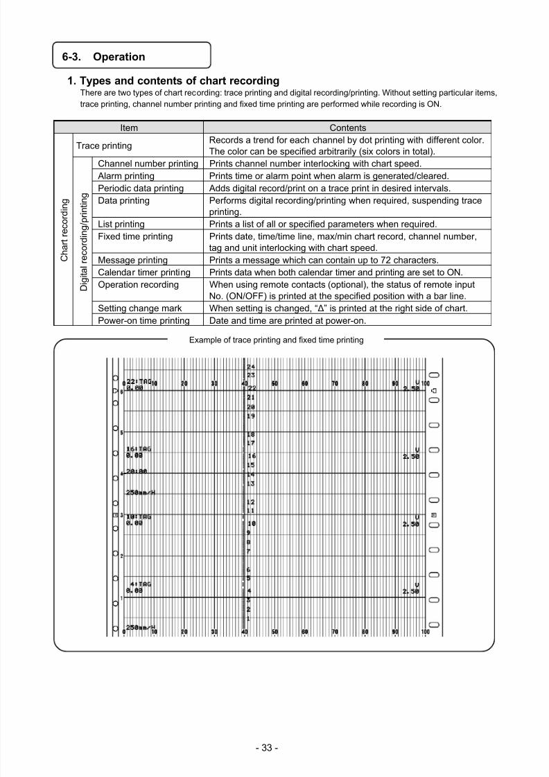
1. Types and contents of chart recordingThere are two types of chart recording: trace printing and digital recording/printing. Without setting particular items,trace printing, channel number printing and fixed time printing are performed while recording is ON.
Item Contents
C h a r t r e c o r d i n g
Trace printing Records a trend for each channel by dot printing with different color.The color can be specified arbitrarily (six colors in total).
D i g i t a
l r e c o r d i n g / p r i n t i n g
Channel number printing Prints channel number interlocking with chart speed. Alarm printing Prints time or alarm point when alarm is generated/cleared.Periodic data printing Adds digital record/print on a trace print in desired intervals.Data printing Performs digital recording/printing when required, suspending trace
printing.List printing Prints a list of all or specified parameters when required.Fixed time printing Prints date, time/time line, max/min chart record, channel number,
tag and unit interlocking with chart speed.Message printing Prints a message which can contain up to 72 characters.
Calendar timer printing Prints data when both calendar timer and printing are set to ON.Operation recording When using remote contacts (optional), the status of remote input
No. (ON/OFF) is printed at the specified position with a bar line.Setting change mark When setting is changed, “Δ” is printed at the right side of chart.Power-on time printing Date and time are printed at power-on.
Example of trace printing and fixed time printing
7/23/2019 AH4000 Multi General INE-851B (1)
http://slidepdf.com/reader/full/ah4000-multi-general-ine-851b-1 37/121
- 34 -
2. Fixed time printing interval When recording is ON at the time of power-on, fixed time printing is performed first.The following table shows printing intervals which vary depending on the printing item.
Time and time line Channel number Chart speedMax/min chart record, tag
and unitVaries depending onthe chart speed
At approx. 6mm intervals,in order of ascendingchannel number
At approx. 84mmintervals
At intervals of channelnumber, in order ofascending channel number
1) Printing intervals of time and time lineTime and time line are printed at the following intervals which vary by the chart speed. The start point of theintervals is 00h 00min.
Chart speed (mm/H) Time and time line (*) Time line only Year/month/date1 - 9 12h 00min only 6h
00h 00min only
10 - 15 4h 2h16 - 30 2h 1h31 - 60 1h ←61 - 119 1h 30min
120 or higher 30min ←(*) When periodic data printing occurs at the same time, only time line is printed.
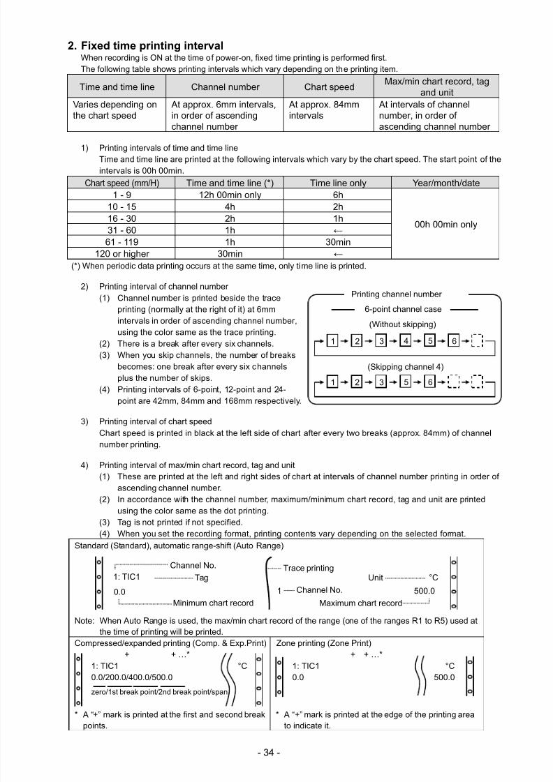
2) Printing interval of channel number(1) Channel number is printed beside the trace
printing (normally at the right of it) at 6mmintervals in order of ascending channel number,using the color same as the trace printing.
(2) There is a break after every six channels.(3) When you skip channels, the number of breaks
becomes: one break after every six channelsplus the number of skips.
(4) Printing intervals of 6-point, 12-point and 24-point are 42mm, 84mm and 168mm respectively.
3) Printing interval of chart speedChart speed is printed in black at the left side of chart after every two breaks (approx. 84mm) of channelnumber printing.
4) Printing interval of max/min chart record, tag and unit(1) These are printed at the left and right sides of chart at intervals of channel number printing in order of
ascending channel number.(2) In accordance with the channel number, maximum/minimum chart record, tag and unit are printed
using the color same as the dot printing.(3) Tag is not printed if not specified.(4) When you set the recording format, printing contents vary depending on the selected format.
Standard (Standard), automatic range-shift (Auto Range)
Note: When Auto Range is used, the max/min chart record of the range (one of the ranges R1 to R5) used atthe time of printing will be printed.
Compressed/expanded printing (Comp. & Exp.Print) Zone printing (Zone Print)+ + …*
1: TIC1 °C0.0/200.0/400.0/500.0
zero/1st break point/2nd break point/span
+ + …*1: TIC1 °C0.0 500.0
* A “+” mark is printed at the first and second breakpoints.
* A “+” mark is printed at the edge of the printing areato indicate it.
Tag
Channel No.
Minimum chart record
Channel No.
Maximum chart record
UnitTrace printing
1: TIC1
0.0 1 500.0
°C
61 2 3 4 5
(Without skipping)
Printing channel number
(Skipping channel 4)
1 2 3 5 6
6-point channel case
7/23/2019 AH4000 Multi General INE-851B (1)
http://slidepdf.com/reader/full/ah4000-multi-general-ine-851b-1 38/121
- 35 -
3. Restrictions on recording1) Digital recording/printing unavailable at certain chart speeds
When chart speed is set to 251mm/H or higher, all digital recordings/printings will not be performed andonly trace printing is performed. However, time line printing, power-on printing, data printing and list printingcan be performed.
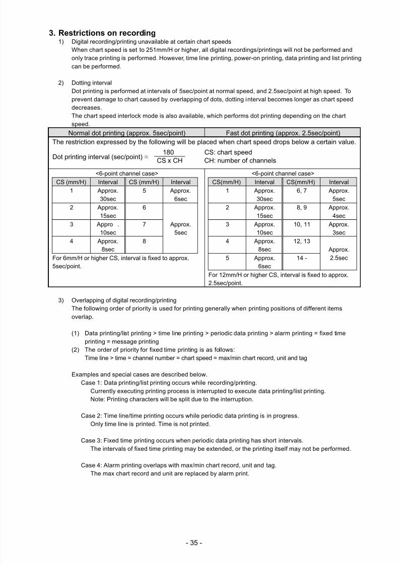
2) Dotting intervalDot printing is performed at intervals of 5sec/point at normal speed, and 2.5sec/point at high speed. To
prevent damage to chart caused by overlapping of dots, dotting interval becomes longer as chart speeddecreases.The chart speed interlock mode is also available, which performs dot printing depending on the chartspeed.
Normal dot printing (approx. 5sec/point) Fast dot printing (approx. 2.5sec/point)The restriction expressed by the following will be placed when chart speed drops below a certain value.
Dot printing interval (sec/point) ≈
<6-point channel case>
CS (mm/H) Interval CS (mm/H) Interval
1 Approx.
30sec
5 Approx.
6sec2 Approx.
15sec6
Approx.5sec
3 Appro .10sec
7
4 Approx.8sec
8
For 6mm/H or higher CS, interval is fixed to approx.5sec/point.
<6-point channel case>
CS(mm/H) Interval CS(mm/H) Interval
1 Approx.
30sec
6, 7 Approx.
5sec2 Approx.
15sec8, 9 Approx.
4sec
3 Approx.10sec
10, 11 Approx.3sec
4 Approx.8sec
12, 13 Approx.2.5sec5 Approx.
6sec14 -
For 12mm/H or higher CS, interval is fixed to approx.2.5sec/point.
3) Overlapping of digital recording/printingThe following order of priority is used for printing generally when printing positions of different itemsoverlap.
(1) Data printing/list printing > time line printing > periodic data printing > alarm printing = fixed timeprinting = message printing
(2) The order of priority for fixed time printing is as follows:Time line > time = channel number = chart speed = max/min chart record, unit and tag
Examples and special cases are described below.Case 1: Data printing/list printing occurs while recording/printing.
Currently executing printing process is interrupted to execute data printing/list printing.Note: Printing characters will be split due to the interruption.
Case 2: Time line/time printing occurs while periodic data printing is in progress.Only time line is printed. Time is not printed.
Case 3: Fixed time printing occurs when periodic data printing has short intervals.The intervals of fixed time printing may be extended, or the printing itself may not be performed.
Case 4: Alarm printing overlaps with max/min chart record, unit and tag.The max chart record and unit are replaced by alarm print.
180 CS: chart speedCS x CH CH: number of channels
7/23/2019 AH4000 Multi General INE-851B (1)
http://slidepdf.com/reader/full/ah4000-multi-general-ine-851b-1 39/121
- 36 -
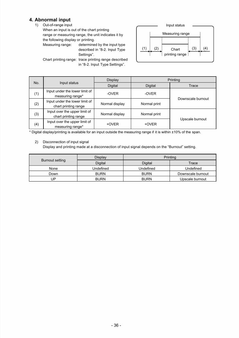
4. Abnormal input1) Out-of-range input
When an input is out of the chart printingrange or measuring range, the unit indicates it bythe following display or printing.Measuring range: determined by the input type
described in “8-2. Input TypeSettings”.
Chart printing range: trace printing range describedin “8-2. Input Type Settings”.
No. Input statusDisplay Printing
Digital Digital Trace
(1)Input under the lower limit of
measuring range*-OVER -OVER
Downscale burnout
(2)Input under the lower limit of
chart printing rangeNormal display Normal print
(3)Input over the upper limit of
chart printing rangeNormal display Normal print
Upscale burnout(4)
Input over the upper limit ofmeasuring range*
+OVER +OVER
* Digital display/printing is available for an input outside the measuring range if it is within ±10% of the span.
2) Disconnection of input signalDisplay and printing made at a disconnection of input signal depends on the “Burnout” setting.
Burnout settingDisplay Printing
Digital Digital Trace
None Undefined Undefined Undefined
Down BURN BURN Downscale burnout
UP BURN BURN Upscale burnout
Input status
Chartprinting range
Measuring range
(1) (2) (3) (4)
7/23/2019 AH4000 Multi General INE-851B (1)
http://slidepdf.com/reader/full/ah4000-multi-general-ine-851b-1 40/121
- 37 -
7. Factory Default Settings
7-1. List of Factory Default Settings
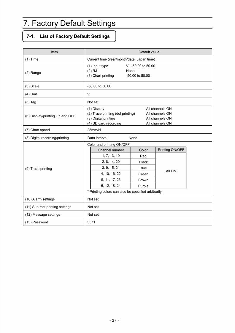
Item Default value
(1) Time Current time (year/month/date: Japan time)
(2) Range
(1) Input type(2) RJ(3) Chart printing
V : -50.00 to 50.00None-50.00 to 50.00
(3) Scale -50.00 to 50.00
(4) Unit V
(5) Tag Not set
(6) Display/printing On and OFF
(1) Display(2) Trace printing (dot printing)
(3) Digital printing(4) SD card recording
All channels ON All channels ON
All channels ON All channels ON
(7) Chart speed 25mm/H
(8) Digital recording/printing Data interval None
(9) Trace printing
Color and printing ON/OFF
Channel number Color Printing ON/OFF
1, 7, 13, 19 Red
All ON
2, 8, 14, 20 Black
3, 9, 15, 21 Blue
4, 10, 16, 22 Green5, 11, 17, 23 Brown
6, 12, 18, 24 Purple
* Printing colors can also be specified arbitrarily.
(10) Alarm settings Not set
(11) Subtract printing settings Not set
(12) Message settings Not set
(13) Password 3571
7/23/2019 AH4000 Multi General INE-851B (1)
http://slidepdf.com/reader/full/ah4000-multi-general-ine-851b-1 41/121
- 38 -
8. Setting Method
8-1. Basic Rules
The following provides general information on setting operations.
Pressing the key can return to the measured value display from any window.
1. Setting items and parameters The unit offers various condition settings to allow users to obtain various recording results and data.Major items of measuring/recording conditions, such as range, scale and chart speed, are called “setting items”,whereas detailed items of each setting item are called “setting parameters” or just “parameters”.
2. Selecting setting item
Press the key on the measured value display. A list of setting items will be displayed.
Use the keys to select a setting item and press the key to confirm yourselection. Some setting items may use hierarchical display.
3. Selecting setting parameter
Select a setting parameter of a setting item.
A cursor is displayed at the left of each parameter. Move the cursor to a desired parameter using the
keys.
4. Key acceptance and acceptance failure
When the cursor does not move by pressing the keys or when a parameter setting
window does not open by pressing the key, it indicates that the keys have been unaccepted. Make sure topress the keys properly and try again.
5. Number of setting items and parameters
Setting items vary depending on the use of option. Also, the number of setting parameters differs by setting item.The items like time and chart speed have a single parameter whereas the items like range, scale and alarm havemultiple parameters requiring channel specification.
Only the parameters necessary for the current setting become available for entry. Unnecessary parameters arereplaced by “*” mark and the cursor does not move to them.
6. Checking setting parameters There are two ways to check setting parameters: “list printing” and “display check”, the former prints all or specifiedsetting items and the latter calls up parameters on the display.
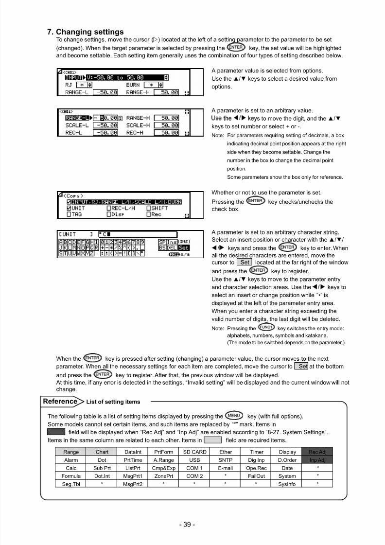
7/23/2019 AH4000 Multi General INE-851B (1)
http://slidepdf.com/reader/full/ah4000-multi-general-ine-851b-1 42/121
- 39 -
7. Changing settings To change settings, move the cursor () located at the left of a setting parameter to the parameter to be set
(changed). When the target parameter is selected by pressing the key, the set value will be highlightedand become settable. Each setting item generally uses the combination of four types of setting described below.
A parameter value is selected from options.
Use the / keys to select a desired value fromoptions.
A parameter is set to an arbitrary value.
s to move the digit, and the /keys to set number or select + or -.
Note: For parameters requiring setting of decimals, a box
indicating decimal point position appears at the right
side when they become settable. Change the
number in the box to change the decimal point
position.
Some parameters show the box only for reference.
Whether or not to use the parameter is set.Pressing the key checks/unchecks thecheck box.
A parameter is set to an arbitrary character string.Select an insert position or character with the //
/ keys and press the key to enter. Whenall the desired characters are entered, move thecursor to Set located at the far right of the window
and press the key to register.Use the / keys to move to the parameter entry
and character selection areas. Use the keys toselect an insert or change position while “•” isdisplayed at the left of the parameter entry area.When you enter a character string exceeding thevalid number of digits, the last digit will be deleted.
Note: Pressing the key switches the entry mode:alphabets, numbers, symbols and katakana.(The mode to be switched depends on the parameter.)
When the key is pressed after setting (changing) a parameter value, the cursor moves to the nextparameter. When all the necessary settings for each item are completed, move the cursor to Set at the bottom
and press the key to register. After that, the previous window will be displayed.
At this time, if any error is detected in the settings, “Invalid setting” will be displayed and the current window will notchange.
The following table is a list of setting items displayed by pressing the key (with full options).Some models cannot set certain items, and such items are replaced by “*” mark. Items in
field will be displayed when “Rec Adj” and “Inp Adj” are enabled according to “8-27. System Settings”.Items in the same column are related to each other. Items in field are required items.
Range Chart DataInt PrtForm SD CARD Ether Timer Display Rec Adj
Alarm Dot PrtTime A.Range USB SNTP Dig Inp D.Order Inp Adj
Calc Sub Prt ListPrt Cmp&Exp COM 1 E-mail Ope.Rec Date *
Formula Dot.Int MsgPrt1 ZonePrt COM 2 * FailOut System *Seg.Tbl * MsgPrt2 * * * * SysInfo *
List of setting itemsReference
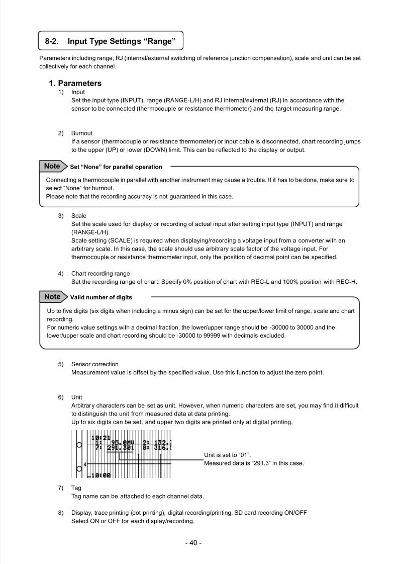
7/23/2019 AH4000 Multi General INE-851B (1)
http://slidepdf.com/reader/full/ah4000-multi-general-ine-851b-1 43/121
- 40 -
8-2. Input Type Settings “Range”
Parameters including range, RJ (internal/external switching of reference junction compensation), scale and unit can be setcollectively for each channel.
1. Parameters1) Input
Set the input type (INPUT), range (RANGE-L/H) and RJ internal/external (RJ) in accordance with thesensor to be connected (thermocouple or resistance thermometer) and the target measuring range.
2) BurnoutIf a sensor (thermocouple or resistance thermometer) or input cable is disconnected, chart recording jumpsto the upper (UP) or lower (DOWN) limit. This can be reflected to the display or output.
3) ScaleSet the scale used for display or recording of actual input after setting input type (INPUT) and range(RANGE-L/H).Scale setting (SCALE) is required when displaying/recording a voltage input from a converter with anarbitrary scale. In this case, the scale should use arbitrary scale factor of the voltage input. Forthermocouple or resistance thermometer input, only the position of decimal point can be specified.
4) Chart recording rangeSet the recording range of chart. Specify 0% position of chart with REC-L and 100% position with REC-H.
5) Sensor correctionMeasurement value is offset by the specified value. Use this function to adjust the zero point.
6) Unit Arbitrary characters can be set as unit. However, when numeric characters are set, you may find it difficultto distinguish the unit from measured data at data printing.Up to six digits can be set, and upper two digits are printed only at digital printing.
Unit is set to “01”.Measured data is “291.3” in this case.
7) Tag
Tag name can be attached to each channel data.
8) Display, trace printing (dot printing), digital recording/printing, SD card recording ON/OFFSelect ON or OFF for each display/recording.
Connecting a thermocouple in parallel with another instrument may cause a trouble. If it has to be done, make sure toselect “None” for burnout.
Please note that the recording accuracy is not guaranteed in this case.
Set “None” for parallel operationNote
Up to five digits (six digits when including a minus sign) can be set for the upper/lower limit of range, scale and chartrecording.For numeric value settings with a decimal fraction, the lower/upper range should be -30000 to 30000 and thelower/upper scale and chart recording should be -30000 to 99999 with decimals excluded.
Valid number of digitsNote
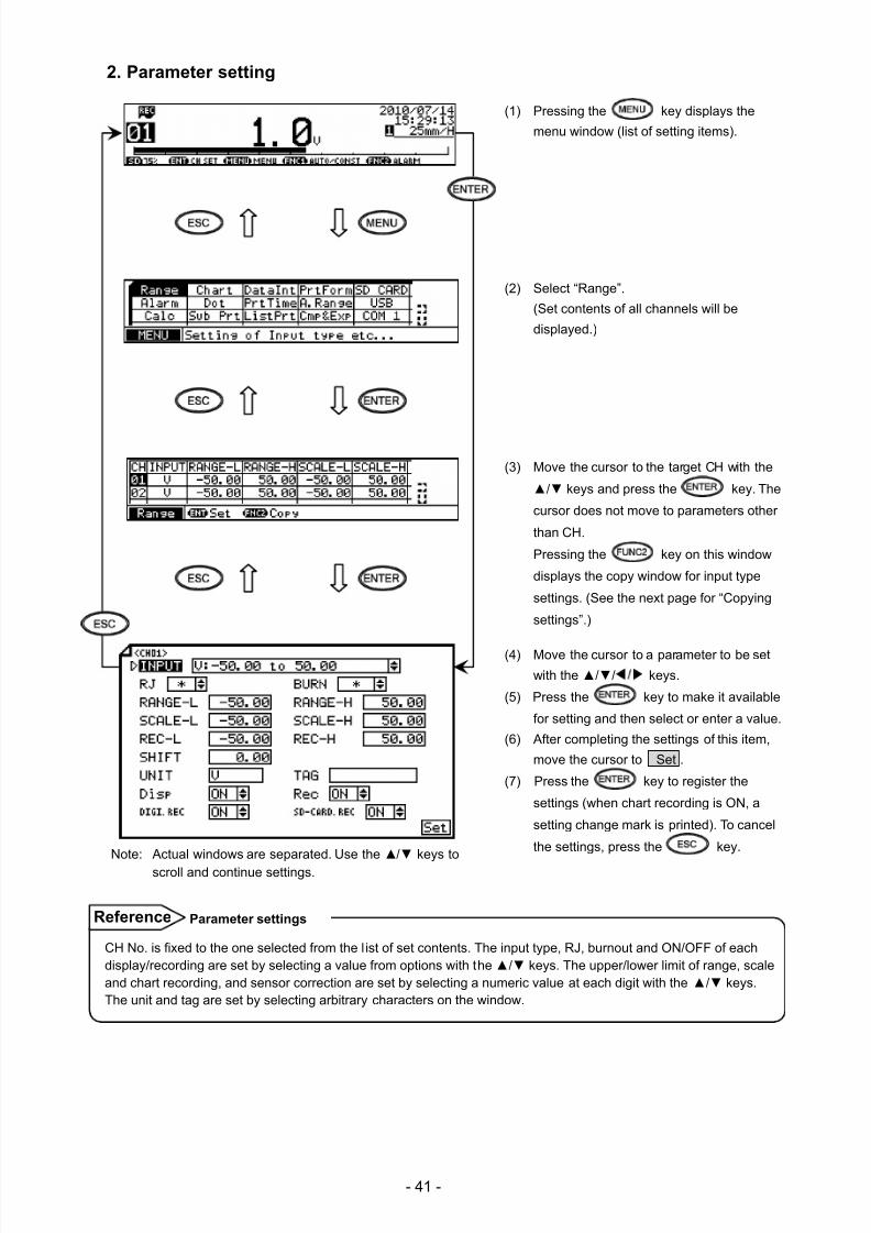
7/23/2019 AH4000 Multi General INE-851B (1)
http://slidepdf.com/reader/full/ah4000-multi-general-ine-851b-1 44/121
- 41 -
2. Parameter setting
(1) Pressing the key displays the
menu window (list of setting items).
(2) Select “Range”.
(Set contents of all channels will be
displayed.)
(3) Move the cursor to the target CH with the
/ keys and press the key. The
cursor does not move to parameters other
than CH.
Pressing the key on this window
displays the copy window for input type
settings. (See the next page for “Copying
settings”.)
(4) Move the cursor to a parameter to be set
with the // keys.
(5) Press the key to make it available
for setting and then select or enter a value.
(6) After completing the settings of this item,
move the cursor to Set .
(7) Press the key to register the
settings (when chart recording is ON, a
setting change mark is printed). To cancel
the settings, press the key. Note: Actual windows are separated. Use the / keys to
scroll and continue settings.
CH No. is fixed to the one selected from the l ist of set contents. The input type, RJ, burnout and ON/OFF of eachdisplay/recording are set by selecting a value from options with the / keys. The upper/lower limit of range, scaleand chart recording, and sensor correction are set by selecting a numeric value at each digit with the / keys.The unit and tag are set by selecting arbitrary characters on the window.
Parameter settingsReference
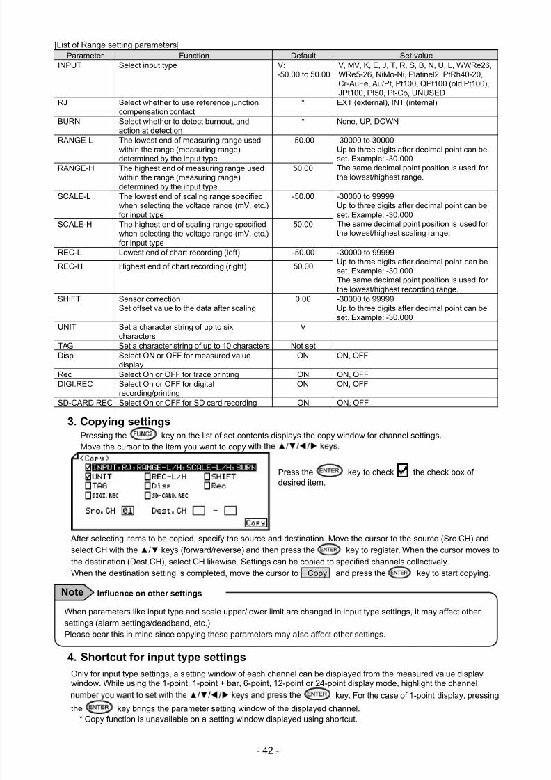
7/23/2019 AH4000 Multi General INE-851B (1)
http://slidepdf.com/reader/full/ah4000-multi-general-ine-851b-1 45/121
- 42 -
[List of Range setting parameters]Parameter Function Default Set value
INPUT Select input type V:-50.00 to 50.00
V, MV, K, E, J, T, R, S, B, N, U, L, WWRe26,WRe5-26, NiMo-Ni, Platinel2, PtRh40-20,Cr-AuFe, Au/Pt, Pt100, QPt100 (old Pt100),JPt100, Pt50, Pt-Co, UNUSED
RJ Select whether to use reference junctioncompensation contact
* EXT (external), INT (internal)
BURN Select whether to detect burnout, andaction at detection
* None, UP, DOWN
RANGE-L The lowest end of measuring range usedwithin the range (measuring range)determined by the input type
-50.00 -30000 to 30000Up to three digits after decimal point can beset. Example: -30.000The same decimal point position is used forthe lowest/highest range.
RANGE-H The highest end of measuring range usedwithin the range (measuring range)determined by the input type
50.00
SCALE-L The lowest end of scaling range specifiedwhen selecting the voltage range (mV, etc.)for input type
-50.00 -30000 to 99999Up to three digits after decimal point can beset. Example: -30.000The same decimal point position is used forthe lowest/highest scaling range.
SCALE-H The highest end of scaling range specifiedwhen selecting the voltage range (mV, etc.)for input type
50.00
REC-L Lowest end of chart recording (left) -50.00 -30000 to 99999Up to three digits after decimal point can be
set. Example: -30.000The same decimal point position is used forthe lowest/highest recording range.
REC-H Highest end of chart recording (right) 50.00
SHIFT Sensor correctionSet offset value to the data after scaling
0.00 -30000 to 99999Up to three digits after decimal point can beset. Example: -30.000
UNIT Set a character string of up to sixcharacters
V
TAG Set a character string of up to 10 characters Not setDisp Select ON or OFF for measured value
displayON ON, OFF
Rec Select On or OFF for trace printing ON ON, OFFDIGI.REC Select On or OFF for digital
recording/printingON ON, OFF
SD-CARD.REC Select On or OFF for SD card recording ON ON, OFF
3. Copying settingsPressing the key on the list of set contents displays the copy window for channel settings.Move the cursor to the item you want to copy w
Press the key to check the check box ofdesired item.
After selecting items to be copied, specify the source and destination. Move the cursor to the source (Src.CH) and
select CH with the / keys (forward/reverse) and then press the key to register. When the cursor moves tothe destination (Dest.CH), select CH likewise. Settings can be copied to specified channels collectively.When the destination setting is completed, move the cursor to Copy and press the key to start copying.
4. Shortcut for input type settings
Only for input type settings, a setting window of each channel can be displayed from the measured value display
window. While using the 1-point, 1-point + bar, 6-point, 12-point or 24-point display mode, highlight the channelkey. For the case of 1-point display, pressing
the key brings the parameter setting window of the displayed channel.* Copy function is unavailable on a setting window displayed using shortcut.
When parameters like input type and scale upper/lower limit are changed in input type settings, it may affect othersettings (alarm settings/deadband, etc.).
Please bear this in mind since copying these parameters may also affect other settings.
Influence on other settingsNote
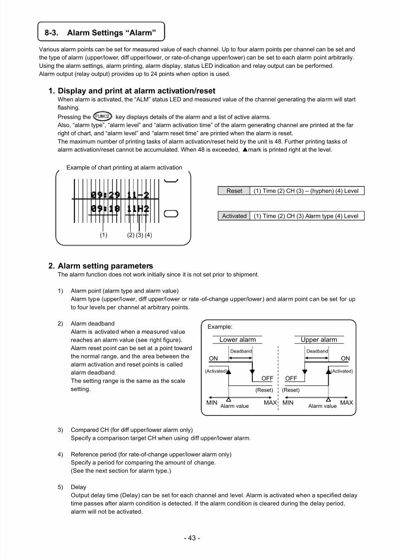
7/23/2019 AH4000 Multi General INE-851B (1)
http://slidepdf.com/reader/full/ah4000-multi-general-ine-851b-1 46/121
- 43 -
8-3. Alarm Settings “Alarm”
Various alarm points can be set for measured value of each channel. Up to four alarm points per channel can be set andthe type of alarm (upper/lower, diff upper/lower, or rate-of-change upper/lower) can be set to each alarm point arbitrarily.Using the alarm settings, alarm printing, alarm display, status LED indication and relay output can be performed. Alarm output (relay output) provides up to 24 points when option is used.
1. Display and print at alarm activation/reset
When alarm is activated, the “ALM” status LED and measured value of the channel generating the alarm will startflashing.
Pressing the key displays details of the alarm and a list of active alarms. Also, “alarm type”, “alarm level” and “alarm activation time” of the alarm generating channel are printed at the farright of chart, and “alarm level” and “alarm reset time” are printed when the alarm is reset.The maximum number of printing tasks of alarm activation/reset held by the unit is 48. Further printing tasks ofalarm activation/reset cannot be accumulated. When 48 is exceeded, mark is printed right at the level.
Reset (1) Time (2) CH (3) – (hyphen) (4) Level
Activated (1) Time (2) CH (3) Alarm type (4) Level
2. Alarm setting parametersThe alarm function does not work initially since it is not set prior to shipment.
1) Alarm point (alarm type and alarm value) Alarm type (upper/lower, diff upper/lower or rate -of-change upper/lower) and alarm point can be set for upto four levels per channel at arbitrary points.
2) Alarm deadband Alarm is activated when a measured valuereaches an alarm value (see right figure). Alarm reset point can be set at a point towardthe normal range, and the area between thealarm activation and reset points is calledalarm deadband.The setting range is the same as the scale
setting.
3) Compared CH (for diff upper/lower alarm only)Specify a comparison target CH when using diff upper/lower alarm.
4) Reference period (for rate-of-change upper/lower alarm only)Specify a period for comparing the amount of change.(See the next section for alarm type.)
5) Delay
Output delay time (Delay) can be set for each channel and level. Alarm is activated when a specified delaytime passes after alarm condition is detected. If the alarm condition is cleared during the delay period,alarm will not be activated.
Example:
Lower alarm
Deadband
(Activated)
(Reset)
Alarm valueMIN MAX
Upper alarm
ON
OFF
Deadband
(Activated)
(Reset)
Alarm value MIN MAX
ON
OFF
(1) (2) (3) (4)
Example of chart printing at alarm activation
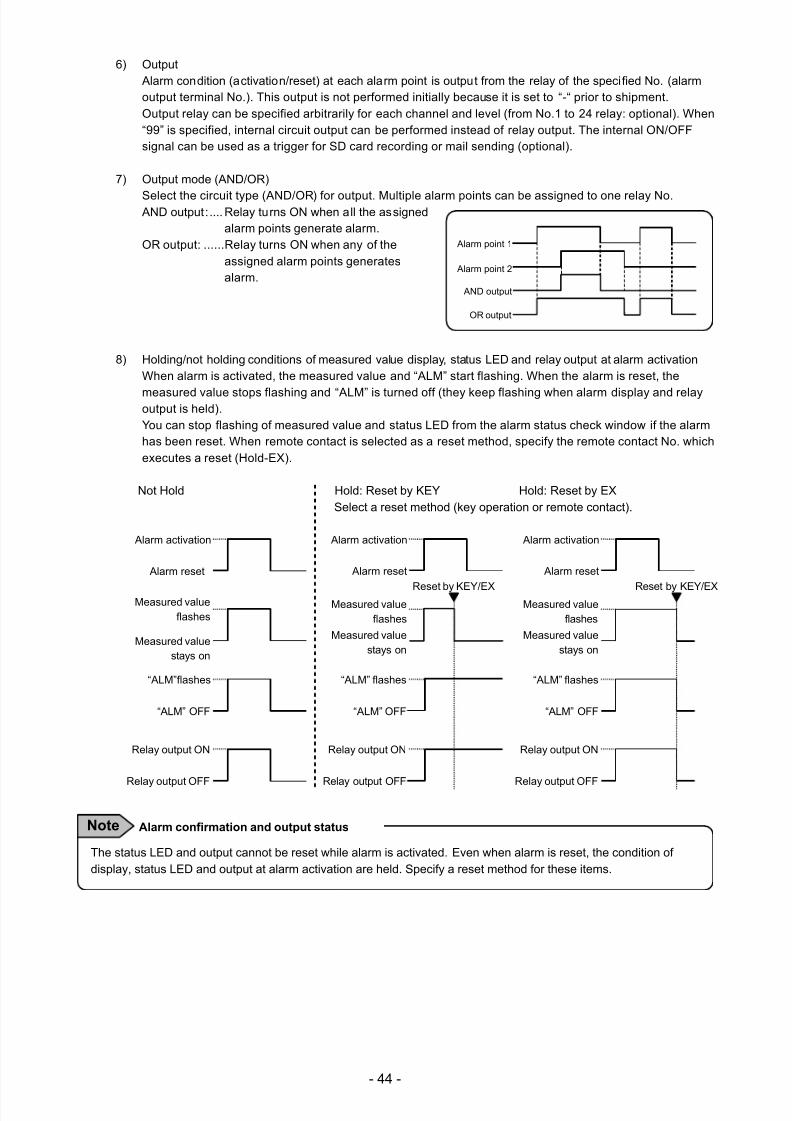
7/23/2019 AH4000 Multi General INE-851B (1)
http://slidepdf.com/reader/full/ah4000-multi-general-ine-851b-1 47/121
- 44 -
6) Output Alarm condition (activation/reset) at each alarm point is output from the relay of the specified No. (alarmoutput terminal No.). This output is not performed initially because it is set to “-“ prior to shipment.Output relay can be specified arbitrarily for each channel and level (from No.1 to 24 relay: optional). When“99” is specified, internal circuit output can be performed instead of relay output. The internal ON/OFFsignal can be used as a trigger for SD card recording or mail sending (optional).
7) Output mode (AND/OR)
Select the circuit type (AND/OR) for output. Multiple alarm points can be assigned to one relay No. AND output: .... Relay turns ON when all the assigned
alarm points generate alarm.OR output: ...... Relay turns ON when any of the
assigned alarm points generatesalarm.
8) Holding/not holding conditions of measured value display, status LED and relay output at alarm activation
When alarm is activated, the measured value and “ALM” start flashing. When the alarm is reset, the
measured value stops flashing and “ALM” is turned off (they keep flashing when alarm display and relayoutput is held).You can stop flashing of measured value and status LED from the alarm status check window if the alarmhas been reset. When remote contact is selected as a reset method, specify the remote contact No. whichexecutes a reset (Hold-EX).
Not Hold Hold: Reset by KEY Hold: Reset by EXSelect a reset method (key operation or remote contact).
Alarm point 1
Alarm point 2
AND output
OR output
The status LED and output cannot be reset while alarm is activated. Even when alarm is reset, the condition ofdisplay, status LED and output at alarm activation are held. Specify a reset method for these items.
Alarm confirmation and output statusNote
Alarm reset
Alarm activation
Measured valuestays on
Measured valueflashes
“ALM” OFF
“ALM”flashes
Relay output OFF
Relay output ON
Reset by KEY/EX
Alarm reset
Alarm activation
Measured valuestays on
Measured valueflashes
“ALM” OFF
“ALM” flashes
Relay output OFF
Relay output ON
Reset by KEY/EX
Alarm reset
Alarm activation
Measured valuestays on
Measured valueflashes
“ALM” OFF
“ALM” flashes
Relay output OFF
Relay output ON
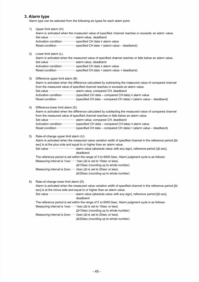
7/23/2019 AH4000 Multi General INE-851B (1)
http://slidepdf.com/reader/full/ah4000-multi-general-ine-851b-1 48/121
- 45 -
3. Alarm type Alarm type can be selected from the following six types for each alarm point.
1) Upper limit alarm (H) Alarm is activated when the measured value of specified channel reaches or exceeds an alarm value.Set value ··························· alarm value, deadband Activation condition ·············· specified CH data ≥ alarm valueReset condition ··················· specified CH data < (alarm value – deadband)
2) Lower limit alarm (L) Alarm is activated when the measured value of specified channel reaches or falls below an alarm value.Set value ··························· alarm value, deadband Activation condition ·············· specified CH data ≤ alarm valueReset condition ··················· specified CH data > (alarm value + deadband)
3) Difference upper limit alarm (B) Alarm is activated when the difference calculated by subtracting the measured value of compared channelfrom the measured value of specified channel reaches or exceeds an alarm value.Set value ··························· alarm value, compared CH, deadband Activation condition ·············· (specified CH data – compared CH data) ≥ alarm value
Reset condition ··················· (specified CH data – compared CH data) < (alarm value – deadband)
4) Difference lower limit alarm (S) Alarm is activated when the difference calculated by subtracting the measured value of compared channelfrom the measured value of specified channel reaches or falls below an alarm value.Set value ··························· alarm value, compared CH, deadband Activation condition ·············· (specified CH data – compared CH data) ≤ alarm valueReset condition ··················· (specified CH data – compared CH data) > (alarm value – deadband)
5) Rate-of-change upper limit alarm (U) Alarm is activated when the measured value variation width of specified channel in the reference period [Δtsec] is at the plus side and equal to or higher than an alarm value.
Set value ··························· alarm value (absolute value with any sign), reference period [Δt sec],deadband
The reference period is set within the range of 0 to 6000.0sec. Alarm judgment cycle is as follows:Measuring interval is 1sec ····· 1sec (Δt is set to 10sec or less)
Δt/10sec (rounding up to whole number)Measuring interval is 2sec ····· 2sec (Δt is set to 20sec or less)
Δt/20sec (rounding up to whole number)
6) Rate-of-change lower limit alarm (D) Alarm is activated when the measured value variation width of specified channel in the reference period [Δtsec] is at the minus side and equal to or higher than an alarm value.Set value ··························· alarm value (absolute value with any sign), reference period [Δt sec],
deadbandThe reference period is set within the range of 0 to 6000.0sec. Alarm judgment cycle is as follows:
Measuring interval is 1sec ····· 1sec (Δt is set to 10sec or less)Δt/10sec (rounding up to whole number)
Measuring interval is 2sec ····· 2sec (Δt is set to 20sec or less)Δt/20sec (rounding up to whole number)
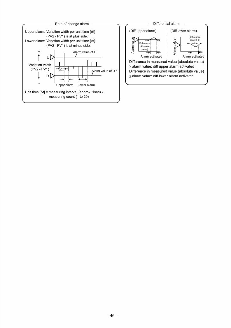
7/23/2019 AH4000 Multi General INE-851B (1)
http://slidepdf.com/reader/full/ah4000-multi-general-ine-851b-1 49/121
- 46 -
Upper alarm: Variation width per unit time [Δt](PV2 - PV1) is at plus side.
Lower alarm: Variation width per unit time [Δt](PV2 - PV1) is at minus side.
Unit time [Δt] = measuring interval (approx. 1sec) xmeasuring count (1 to 20)
ΔtVariation width
(PV2 - PV1)
-
+
D
U
Upper alarm Lower alarm
Alarm value of D *
Alarm value of U
Rate-of-change alarm
Difference in measured value (absolute value)≥ alarm value: diff upper alarm activated Difference in measured value (absolute value)≤ alarm value: diff lower alarm activated
(Diff upper alarm)
Alarm activated
A l a r m
v a
l u e
Difference(Absolute
value)
Alarm activated
A l a r m
v a
l u e
Difference(Absolute
value)
(Diff lower alarm)
Differential alarm
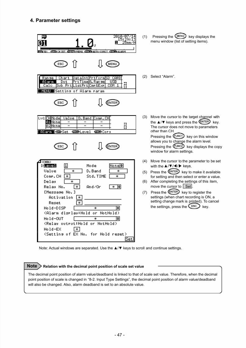
7/23/2019 AH4000 Multi General INE-851B (1)
http://slidepdf.com/reader/full/ah4000-multi-general-ine-851b-1 50/121
- 47 -
4. Parameter settings
(1) Pressing the key displays themenu window (list of setting items).
(2) Select “Alarm”.
(3) Move the cursor to the target channel with
the / keys and press the key.The cursor does not move to parametersother than CH.
Pressing the key on this windowallows you to change the alarm level.
Pressing the key displays the copywindow for alarm settings.
(4) Move the cursor to the parameter to be setwith the .
(5) Press the key to make it availablefor setting and then select or enter a value.
(6) After completing the settings of this item,move the cursor to Set .
(7) Press the key to register thesettings (when chart recording is ON, asetting change mark is printed). To cancel
the settings, press the key.
Note: Actual windows are separated. Use the / keys to scroll and continue settings.
The decimal point position of alarm value/deadband is linked to that of scale set value. Therefore, when the decimalpoint position of scale is changed in “8-2. Input Type Settings”, the decimal point position of alarm value/deadbandwill also be changed. Also, alarm deadband is set to an absolute value.
Relation with the decimal point position of scale set valueNote
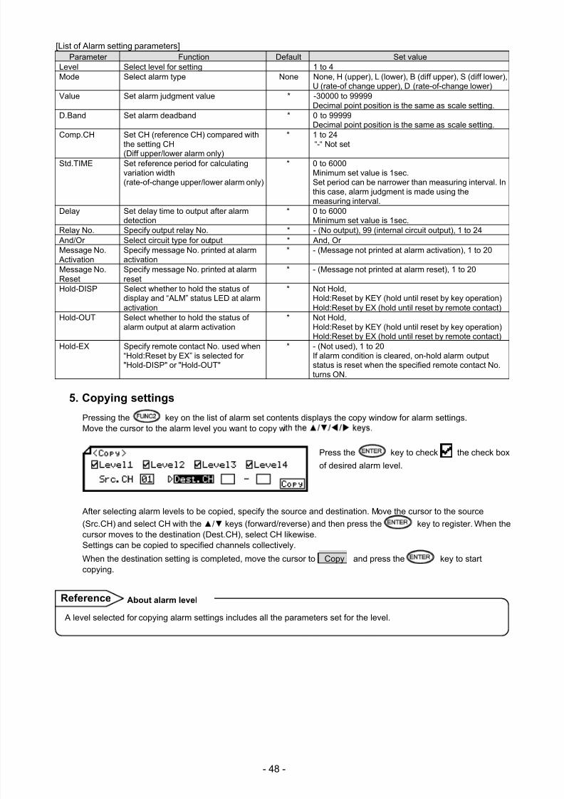
7/23/2019 AH4000 Multi General INE-851B (1)
http://slidepdf.com/reader/full/ah4000-multi-general-ine-851b-1 51/121
- 48 -
[List of Alarm setting parameters]Parameter Function Default Set value
Level Select level for setting 1 to 4 Mode Select alarm type None None, H (upper), L (lower), B (diff upper), S (diff lower),
U (rate-of change upper), D (rate-of-change lower)Value Set alarm judgment value * -30000 to 99999
Decimal point position is the same as scale setting.D.Band Set alarm deadband * 0 to 99999
Decimal point position is the same as scale setting. Comp.CH Set CH (reference CH) compared with
the setting CH(Diff upper/lower alarm only)
* 1 to 24“-“ Not set
Std.TIME Set reference period for calculatingvariation width(rate-of-change upper/lower alarm only)
* 0 to 6000Minimum set value is 1sec.Set period can be narrower than measuring interval. Inthis case, alarm judgment is made using themeasuring interval.
Delay Set delay time to output after alarmdetection
* 0 to 6000Minimum set value is 1sec.
Relay No. Specify output relay No. * - (No output), 99 (internal circuit output), 1 to 24 And/Or Select circuit type for output * And, OrMessage No. Activation
Specify message No. printed at alarmactivation
* - (Message not printed at alarm activation), 1 to 20
Message No.
Reset
Specify message No. printed at alarm
reset
* - (Message not printed at alarm reset), 1 to 20
Hold-DISP Select whether to hold the status ofdisplay and “ALM” status LED at alarmactivation
* Not Hold, Hold:Reset by KEY (hold until reset by key operation)Hold:Reset by EX (hold until reset by remote contact)
Hold-OUT Select whether to hold the status ofalarm output at alarm activation
* Not Hold, Hold:Reset by KEY (hold until reset by key operation)Hold:Reset by EX (hold until reset by remote contact)
Hold-EX Specify remote contact No. used when“Hold:Reset by EX” is selected for"Hold-DISP" or "Hold-OUT"
* - (Not used), 1 to 20If alarm condition is cleared, on-hold alarm outputstatus is reset when the specified remote contact No.turns ON.
5. Copying settings
Pressing the key on the list of alarm set contents displays the copy window for alarm settings.Move the cursor to the alarm level you want to copy w
Press the key to check the check box
of desired alarm level.
After selecting alarm levels to be copied, specify the source and destination. Move the cursor to the source
(Src.CH) and select CH with the / keys (forward/reverse) and then press the key to register. When thecursor moves to the destination (Dest.CH), select CH likewise.Settings can be copied to specified channels collectively.
When the destination setting is completed, move the cursor to Copy and press the key to startcopying.
A level selected for copying alarm settings includes all the parameters set for the level.
About alarm levelReference
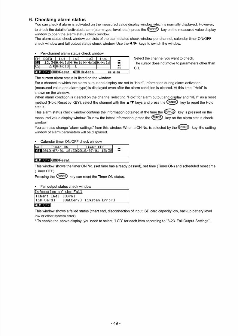
7/23/2019 AH4000 Multi General INE-851B (1)
http://slidepdf.com/reader/full/ah4000-multi-general-ine-851b-1 52/121
- 49 -
6. Checking alarm statusYou can check if alarm is activated on the measured value display window which is normally displayed. However,
to check the detail of activated alarm (alarm type, level, etc.), press the key on the measured value displaywindow to open the alarm status check window.The alarm status check window consists of the alarm status check window per channel, calendar timer ON/OFFcheck window and fail output status check window. Use the keys to switch the window.
• Per-channel alarm status check window
Select the channel you want to check.The cursor does not move to parameters other thanCH.
The current alarm status is listed on the window.For a channel to which the alarm output and display are set to “Hold”, information during alarm activation(measured value and alarm type) is displayed even after the alarm condition is cleared. At this time, “Hold” isshown on the window.When alarm condition is cleared on the channel selecting “Hold” for alarm output and display and “KEY” as a reset
method (Hold:Reset by KEY), select the channel with the / keys and press the key to reset the Holdstatus.
This alarm status check window contains the information obtained at the time the key is pressed on the
measured value display window. To view the latest information, press the key on the alarm status checkwindow.
You can also change "alarm settings" from this window. When a CH No. is selected by the key, the settingwindow of alarm parameters will be displayed.
• Calendar timer ON/OFF check window
This window shows the timer ON No. (set time has already passed), set time (Timer ON) and scheduled reset time(Timer OFF).
Pressing the key can reset the Timer ON status.
• Fail output status check window
This window shows a failed status (chart end, disconnection of input, SD card capacity low, backup battery levellow or other system error).* To enable the above display, you need to select “LCD” for each item according to “8-23. Fail Output Settings”.
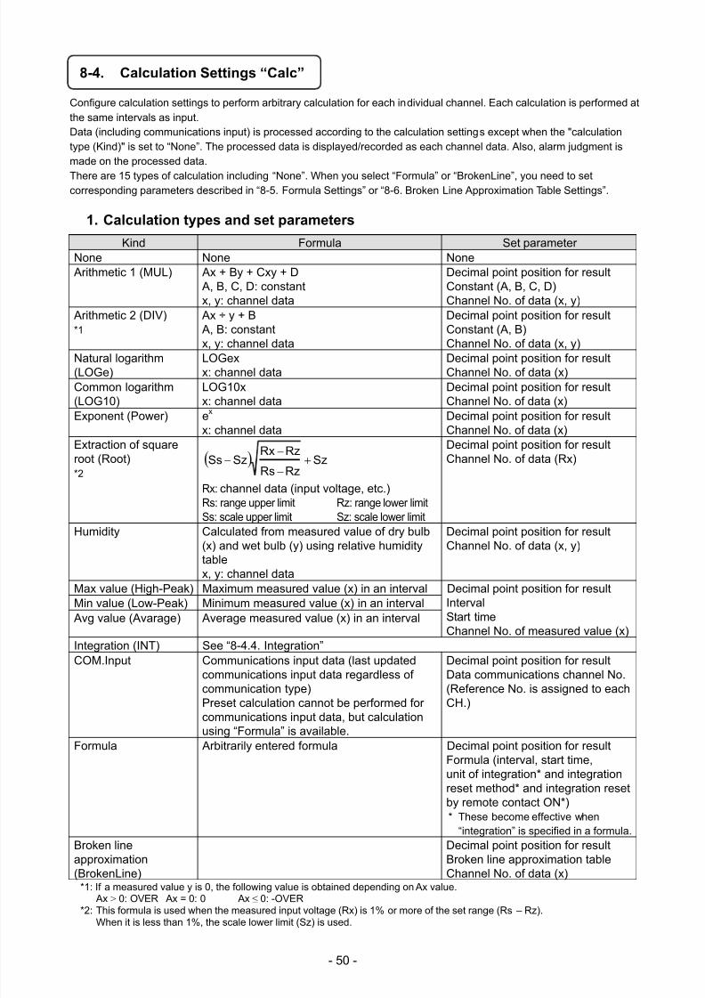
7/23/2019 AH4000 Multi General INE-851B (1)
http://slidepdf.com/reader/full/ah4000-multi-general-ine-851b-1 53/121
- 50 -
8-4. Calculation Settings “Calc”
Configure calculation settings to perform arbitrary calculation for each individual channel. Each calculation is performed atthe same intervals as input.Data (including communications input) is processed according to the calculation settings except when the "calculationtype (Kind)" is set to “None”. The processed data is displayed/recorded as each channel data. Also, alarm judgment ismade on the processed data.
There are 15 types of calculation including “None”. When you select “Formula” or “BrokenLine”, you need to setcorresponding parameters described in “8-5. Formula Settings” or “8-6. Broken Line Approximation Table Settings”.
1. Calculation types and set parameters
Kind Formula Set parameterNone None None Arithmetic 1 (MUL) Ax + By + Cxy + D
A, B, C, D: constantx, y: channel data
Decimal point position for resultConstant (A, B, C, D)Channel No. of data (x, y)
Arithmetic 2 (DIV)*1
Ax ÷ y + B A, B: constant
x, y: channel data
Decimal point position for resultConstant (A, B)
Channel No. of data (x, y)Natural logarithm(LOGe)
LOGexx: channel data
Decimal point position for resultChannel No. of data (x)
Common logarithm(LOG10)
LOG10xx: channel data
Decimal point position for resultChannel No. of data (x)
Exponent (Power) ex
x: channel dataDecimal point position for resultChannel No. of data (x)
Extraction of squareroot (Root)*2
SzRzRs
RzRxSzSs
Rx: channel data (input voltage, etc.)
Rs: range upper limit Rz: range lower limit
Ss: scale upper limit Sz: scale lower limit
Decimal point position for resultChannel No. of data (Rx)
Humidity Calculated from measured value of dry bulb(x) and wet bulb (y) using relative humiditytablex, y: channel data
Decimal point position for resultChannel No. of data (x, y)
Max value (High-Peak) Maximum measured value (x) in an interval Decimal point position for resultIntervalStart timeChannel No. of measured value (x)
Min value (Low-Peak) Minimum measured value (x) in an interval Avg value (Avarage) Average measured value (x) in an interval
Integration (INT) See “8-4.4. Integration”COM.Input Communications input data (last updated
communications input data regardless ofcommunication type)
Preset calculation cannot be performed forcommunications input data, but calculationusing “Formula” is available.
Decimal point position for resultData communications channel No.(Reference No. is assigned to each
CH.)
Formula Arbitrarily entered formula Decimal point position for resultFormula (interval, start time,unit of integration* and integrationreset method* and integration resetby remote contact ON*)* These become effective when
“integration” is specified in a formula. Broken lineapproximation
(BrokenLine)
Decimal point position for resultBroken line approximation table
Channel No. of data (x)*1: If a measured value y is 0, the following value is obtained depending on Ax value. Ax > 0: OVER Ax = 0: 0 Ax ≤ 0: -OVER
*2: This formula is used when the measured input voltage (Rx) is 1% or more of the set range (Rs – Rz).When it is less than 1%, the scale lower limit (Sz) is used.
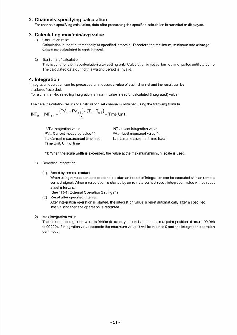
7/23/2019 AH4000 Multi General INE-851B (1)
http://slidepdf.com/reader/full/ah4000-multi-general-ine-851b-1 54/121
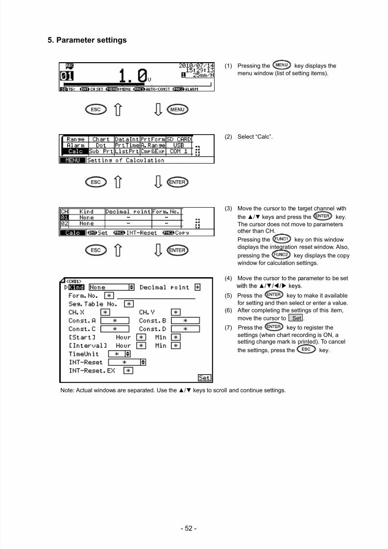
7/23/2019 AH4000 Multi General INE-851B (1)
http://slidepdf.com/reader/full/ah4000-multi-general-ine-851b-1 55/121
- 52 -
5. Parameter settings
(1) Pressing the key displays themenu window (list of setting items).
(2) Select “Calc”.
(3) Move the cursor to the target channel with
the / keys and press the key.The cursor does not move to parametersother than CH.
Pressing the key on this windowdisplays the integration reset window. Also,
pressing the key displays the copywindow for calculation settings.
(4) Move the cursor to the parameter to be set
(5) Press the key to make it availablefor setting and then select or enter a value.
(6) After completing the settings of this item,move the cursor to Set .
(7) Press the key to register thesettings (when chart recording is ON, asetting change mark is printed). To cancel
the settings, press the key.
Note: Actual windows are separated. Use the / keys to scroll and continue settings.
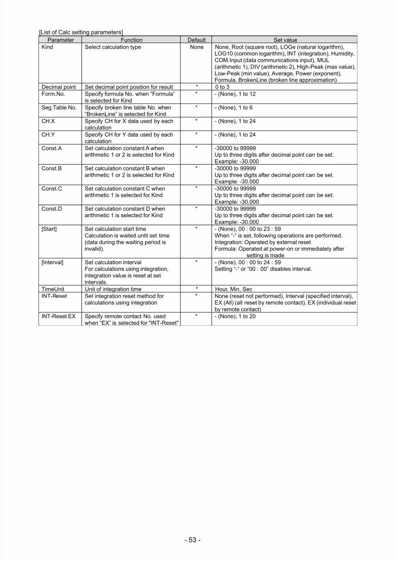
7/23/2019 AH4000 Multi General INE-851B (1)
http://slidepdf.com/reader/full/ah4000-multi-general-ine-851b-1 56/121
- 53 -
[List of Calc setting parameters]Parameter Function Default Set value
Kind Select calculation type None None, Root (square root), LOGe (natural logarithm),LOG10 (common logarithm), INT (integration), Humidity,COM.Input (data communications input), MUL(arithmetic 1), DIV (arithmetic 2), High-Peak (max value),Low-Peak (min value), Average, Power (exponent),Formula, BrokenLine (broken line approximation)
Decimal point Set decimal point position for result * 0 to 3Form.No. Specify formula No. when “Formula”
is selected for Kind* - (None), 1 to 12
Seg.Table No. Specify broken line table No. when“BrokenLine” is selected for Kind
* - (None), 1 to 6
CH.X Specify CH for X data used by eachcalculation
* - (None), 1 to 24
CH.Y Specify CH for Y data used by eachcalculation
* - (None), 1 to 24
Const.A Set calculation constant A whenarithmetic 1 or 2 is selected for Kind
* -30000 to 99999Up to three digits after decimal point can be set.Example: -30.000
Const.B Set calculation constant B whenarithmetic 1 or 2 is selected for Kind
* -30000 to 99999Up to three digits after decimal point can be set.Example: -30.000
Const.C Set calculation constant C when
arithmetic 1 is selected for Kind
* -30000 to 99999
Up to three digits after decimal point can be set.Example: -30.000Const.D Set calculation constant D when
arithmetic 1 is selected for Kind* -30000 to 99999
Up to three digits after decimal point can be set.Example: -30.000
[Start] Set calculation start timeCalculation is waited until set time(data during the waiting period isinvalid).
* - (None), 00 : 00 to 23 : 59When “-“ is set, following operations are performed.Integration: Operated by external resetFormula: Operated at power-on or immediately after
setting is made[Interval] Set calculation interval
For calculations using integration,integration value is reset at setintervals.
* - (None), 00 : 00 to 24 : 59Setting “-“ or “00 : 00” disables interval.
TimeUnit Unit of integration time * Hour, Min, Sec
INT-Reset Set integration reset method forcalculations using integration
* None (reset not performed), Interval (specified interval),EX (All) (all reset by remote contact), EX (individual resetby remote contact)
INT-Reset.EX Specify remote contact No. usedwhen “EX” is selected for "INT-Reset"
* - (None), 1 to 20
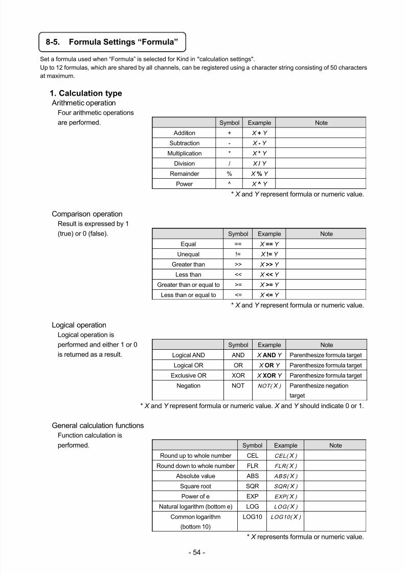
7/23/2019 AH4000 Multi General INE-851B (1)
http://slidepdf.com/reader/full/ah4000-multi-general-ine-851b-1 57/121
- 54 -
8-5. Formula Settings “Formula”
Set a formula used when “Formula” is selected for Kind in "calculation settings".Up to 12 formulas, which are shared by all channels, can be registered using a character string consisting of 50 charactersat maximum.
1. Calculation type
Arithmetic operationFour arithmetic operations
are performed. Symbol Example Note
Addition + X + Y
Subtraction - X - Y
Multiplication * X * Y
Division / X / Y
Remainder % X % Y
Power ^ X ^ Y
* X and Y represent formula or numeric value.
Comparison operationResult is expressed by 1
(true) or 0 (false). Symbol Example Note
Equal == X == Y
Unequal != X != Y
Greater than >> X >> Y
Less than << X << Y
Greater than or equal to >= X >= Y
Less than or equal to <= X <= Y
* X and Y represent formula or numeric value.
Logical operationLogical operation is
performed and either 1 or 0
is returned as a result.
Symbol Example Note
Logical AND AND X AND Y Parenthesize formula target
Logical OR OR X OR Y Parenthesize formula target
Exclusive OR XOR X XOR Y Parenthesize formula target
Negation NOT NOT( X ) Parenthesize negation
target
* X and Y represent formula or numeric value. X and Y should indicate 0 or 1.
General calculation functionsFunction calculation is
performed. Symbol Example Note
Round up to whole number CEL CEL( X )
Round down to whole number FLR FLR( X )
Absolute value ABS ABS( X )
Square root SQR SQR( X )
Power of e EXP EXP( X )
Natural logarithm (bottom e) LOG LOG( X )
Common logarithm
(bottom 10)
LOG10 LOG10( X )
* X represents formula or numeric value.
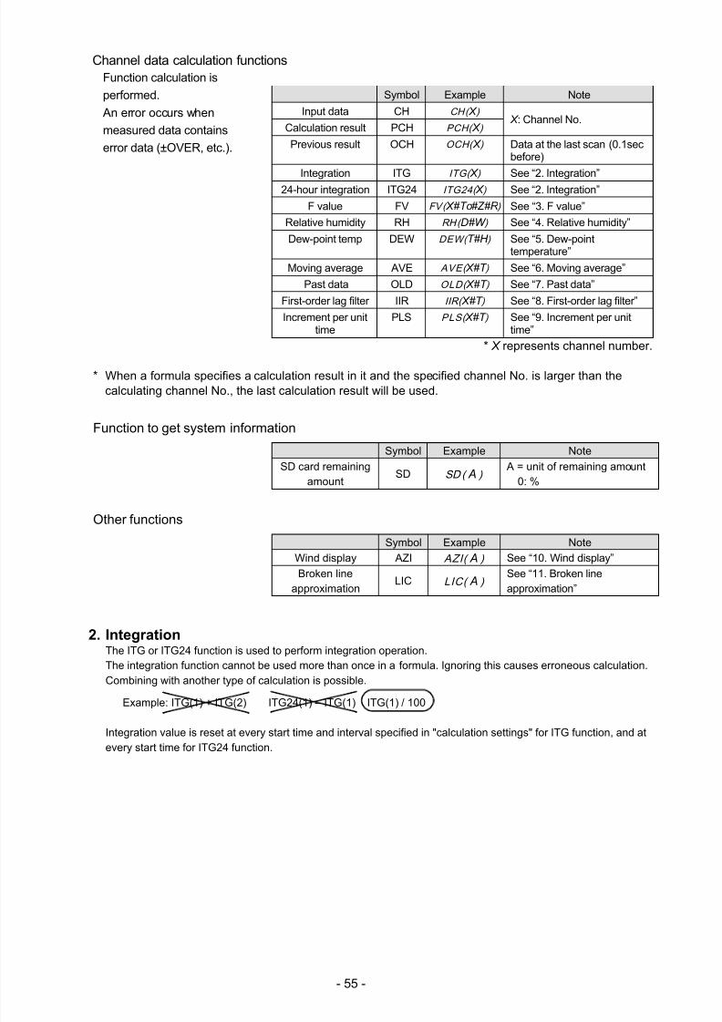
7/23/2019 AH4000 Multi General INE-851B (1)
http://slidepdf.com/reader/full/ah4000-multi-general-ine-851b-1 58/121
- 55 -
Channel data calculation functionsFunction calculation is
performed.
An error occurs when
measured data contains
error data (±OVER, etc.).
Symbol Example Note
Input data CH CH( X ) X : Channel No.
Calculation result PCH PCH( X )
Previous result OCH OCH( X ) Data at the last scan (0.1secbefore)
Integration ITGITG( X )
See “2. Integration”24-hour integration ITG24 ITG24( X ) See “2. Integration”
F value FV FV( X#To#Z#R ) See “3. F value”
Relative humidity RH RH( D#W ) See “4. Relative humidity”
Dew-point temp DEW DEW( T#H ) See “5. Dew-pointtemperature”
Moving average AVE AVE( X#T ) See “6. Moving average”
Past data OLD OLD( X#T ) See “7. Past data”
First-order lag filter IIR IIR( X#T ) See “8. First-order lag filter”
Increment per unittime
PLS PLS( X#T ) See “9. Increment per unittime”
* X represents channel number.
* When a formula specifies a calculation result in it and the specified channel No. is larger than thecalculating channel No., the last calculation result will be used.
Function to get system information
Symbol Example Note
SD card remainingamount
SD SD ( A ) A = unit of remaining amount
0: %
Other functions
Symbol Example NoteWind display AZI AZI( A ) See “10. Wind display”
Broken lineapproximation
LIC LIC( A ) See “11. Broken lineapproximation”
2. IntegrationThe ITG or ITG24 function is used to perform integration operation.The integration function cannot be used more than once in a formula. Ignoring this causes erroneous calculation.Combining with another type of calculation is possible.
Example: ITG(1) + ITG(2) ITG24(1) – ITG(1) ITG(1) / 100
Integration value is reset at every start time and interval specified in "calculation settings" for ITG function, and atevery start time for ITG24 function.
7/23/2019 AH4000 Multi General INE-851B (1)
http://slidepdf.com/reader/full/ah4000-multi-general-ine-851b-1 59/121
- 56 -
1) Normal integration
Integration value is reset at every reference time and interval.Entering a formulaITG(X)
X: Channel No. of integration target
Calculation detailDn = Dn-1 + (PVn + PVn-1) x (Tn-Tn-1) ÷ 2
Dn: Integration result Dn-1: Last integration resultPVn: Integration target data PVn-1: Last integration target dataTn: Calculation time Tn-1: Last calculation time
If error data (±OVER, etc.) is included, calculation will not be performed and the last result will be valid.
2) 24-hour integrationIntegration value is reset only at reference time(start time).
Entering a formulaITG24(X)
X: Channel No. of integration target
Calculation detail is the same as normal integration.
3. F valueEntering a formula
FV(X#To#Z#R)X: Channel No. of calculation target, To: Reference temperature for F value calculation, Z: Z value, R: Starttemperature for F value calculation
F value is obtained from the following calculation.∫10 Adt where A = (T - To) ÷ Z T: Calculation target channel data
When T value exceeds R value, F value will be reset to 0.
4. Relative humidityEntering a formula
RH(D#W)D: Channel No. of dry bulb temperature, W: Channel No. of wet bulb temperature
Relative humidity is obtained from the following formula.((B - 0.000662 x 1013.0 x (Ddata – Wdata)) ÷ A) x 100 A: Dry bulb saturated water vapor pressure, B: Wet bulb saturated water vapor pressure, Ddata: Dry bulbtemperature, Wdata: Wet bulb temperature
The following formula is used to obtain a value of saturated water vapor pressure.6.1121 x EXP ((17.502 x T) ÷ (240.9 + T)) T: Temperature
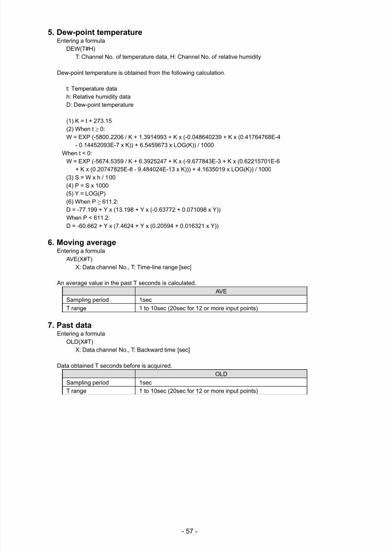
7/23/2019 AH4000 Multi General INE-851B (1)
http://slidepdf.com/reader/full/ah4000-multi-general-ine-851b-1 60/121
- 57 -
5. Dew-point temperatureEntering a formula
DEW(T#H)T: Channel No. of temperature data, H: Channel No. of relative humidity
Dew-point temperature is obtained from the following calculation.
t: Temperature data
h: Relative humidity dataD: Dew-point temperature
(1) K = t + 273.15(2) When t ≥ 0:W = EXP (-5800.2206 / K + 1.3914993 + K x (-0.048640239 + K x (0.41764768E-4
- 0.14452093E-7 x K)) + 6.5459673 x LOG(K)) / 1000When t < 0:
W = EXP (-5674.5359 / K + 6.3925247 + K x (-9.677843E-3 + K x (0.62215701E-6+ K x (0.20747825E-8 - 9.484024E-13 x K))) + 4.1635019 x LOG(K)) / 1000
(3) S = W x h / 100(4) P = S x 1000
(5) Y = LOG(P)(6) When P ≥ 611.2:D = -77.199 + Y x (13.198 + Y x (-0.63772 + 0.071098 x Y))When P < 611.2:D = -60.662 + Y x (7.4624 + Y x (0.20594 + 0.016321 x Y))
6. Moving averageEntering a formula
AVE(X#T)X: Data channel No., T: Time-line range [sec]
An average value in the past T seconds is calculated.
AVESampling period 1sec
T range 1 to 10sec (20sec for 12 or more input points)
7. Past dataEntering a formula
OLD(X#T)X: Data channel No., T: Backward time [sec]
Data obtained T seconds before is acquired.
OLD
Sampling period 1sec
T range 1 to 10sec (20sec for 12 or more input points)
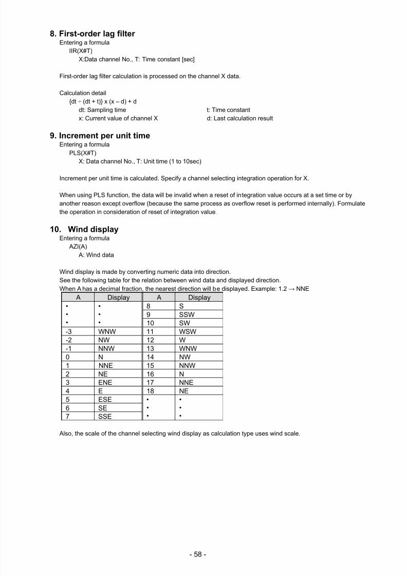
7/23/2019 AH4000 Multi General INE-851B (1)
http://slidepdf.com/reader/full/ah4000-multi-general-ine-851b-1 61/121
- 58 -
8. First-order lag filterEntering a formula
IIR(X#T)X:Data channel No., T: Time constant [sec]
First-order lag filter calculation is processed on the channel X data.
Calculation detail
dt ÷ (dt + t) x (x – d) + ddt: Sampling time t: Time constantx: Current value of channel X d: Last calculation result
9. Increment per unit timeEntering a formula
PLS(X#T)X: Data channel No., T: Unit time (1 to 10sec)
Increment per unit time is calculated. Specify a channel selecting integration operation for X.
When using PLS function, the data will be invalid when a reset of integration value occurs at a set time or by
another reason except overflow (because the same process as overflow reset is performed internally). Formulatethe operation in consideration of reset of integration value.
10. Wind displayEntering a formula
AZI(A) A: Wind data
Wind display is made by converting numeric data into direction.See the following table for the relation between wind data and displayed direction.When A has a decimal fraction, the nearest direction will be displayed. Example: 1.2 → NNE
A Display A Display•••
•••
8 S9 SSW10 SW
-3 WNW 11 WSW-2 NW 12 W-1 NNW 13 WNW0 N 14 NW1 NNE 15 NNW2 NE 16 N3 ENE 17 NNE4 E 18 NE5 ESE •
••
•••
6 SE7 SSE
Also, the scale of the channel selecting wind display as calculation type uses wind scale.
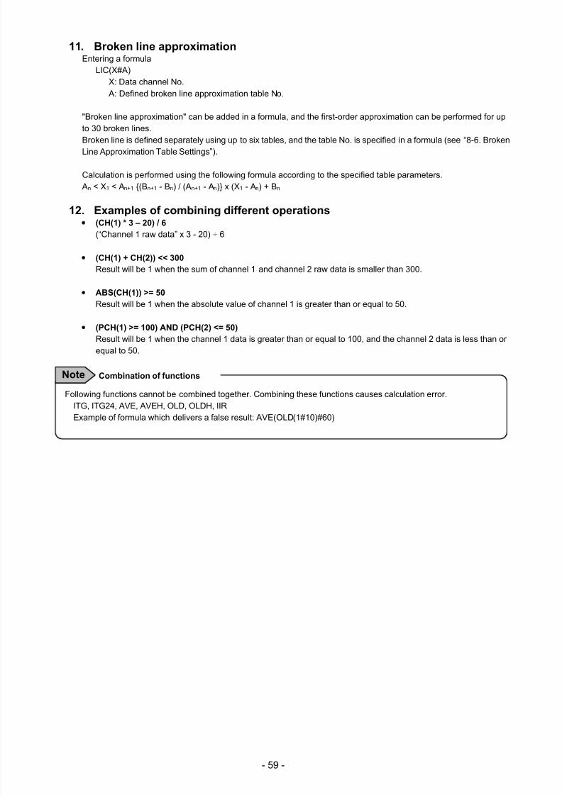
7/23/2019 AH4000 Multi General INE-851B (1)
http://slidepdf.com/reader/full/ah4000-multi-general-ine-851b-1 62/121
- 59 -
11. Broken line approximationEntering a formula
LIC(X#A)X: Data channel No. A: Defined broken line approximation table No.
"Broken line approximation" can be added in a formula, and the first-order approximation can be performed for upto 30 broken lines.
Broken line is defined separately using up to six tables, and the table No. is specified in a formula (see “8-6. BrokenLine Approximation Table Settings”).
Calculation is performed using the following formula according to the specified table parameters. An < X1 < An+1 (Bn+1 - Bn) / (An+1 - An) x (X1 - An) + Bn
12. Examples of combining different operations(CH(1) * 3 – 20) / 6
(“Channel 1 raw data” x 3 - 20) ÷ 6
(CH(1) + CH(2)) << 300
Result will be 1 when the sum of channel 1 and channel 2 raw data is smaller than 300.
ABS(CH(1)) >= 50
Result will be 1 when the absolute value of channel 1 is greater than or equal to 50.
(PCH(1) >= 100) AND (PCH(2) <= 50)
Result will be 1 when the channel 1 data is greater than or equal to 100, and the channel 2 data is less than orequal to 50.
Following functions cannot be combined together. Combining these functions causes calculation error.ITG, ITG24, AVE, AVEH, OLD, OLDH, IIR
Example of formula which delivers a false result: AVE(OLD(1#10)#60)
Combination of functionsNote
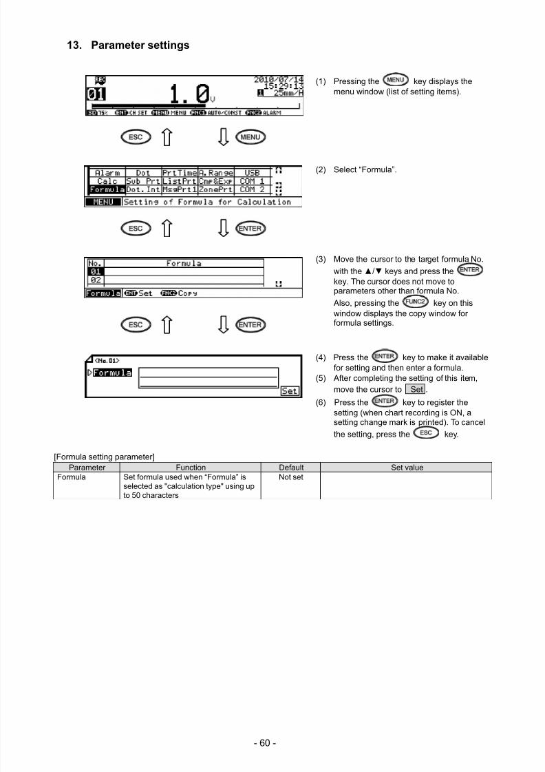
7/23/2019 AH4000 Multi General INE-851B (1)
http://slidepdf.com/reader/full/ah4000-multi-general-ine-851b-1 63/121
- 60 -
13. Parameter settings
(1) Pressing the key displays themenu window (list of setting items).
(2) Select “Formula”.
(3) Move the cursor to the target formula No.
with the / keys and press thekey. The cursor does not move toparameters other than formula No.
Also, pressing the key on thiswindow displays the copy window forformula settings.
(4) Press the key to make it availablefor setting and then enter a formula.
(5) After completing the setting of this item,move the cursor to Set .
(6) Press the key to register thesetting (when chart recording is ON, asetting change mark is printed). To cancel
the setting, press the key.
[Formula setting parameter]Parameter Function Default Set value
Formula Set formula used when “Formula” isselected as "calculation type" using upto 50 characters
Not set
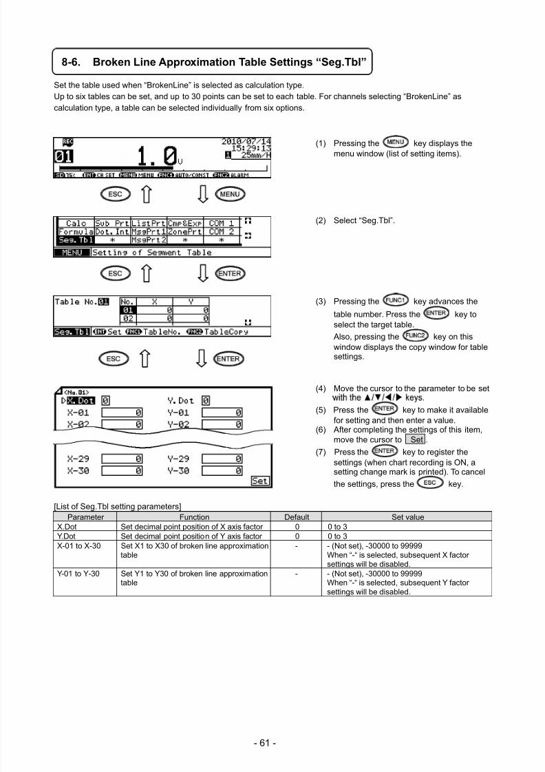
7/23/2019 AH4000 Multi General INE-851B (1)
http://slidepdf.com/reader/full/ah4000-multi-general-ine-851b-1 64/121
- 61 -
8-6. Broken Line Approximation Table Settings “Seg.Tbl”
Set the table used when “BrokenLine” is selected as calculation type.Up to six tables can be set, and up to 30 points can be set to each table. For channels selecting “BrokenLine” ascalculation type, a table can be selected individually from six options.
(1) Pressing the key displays themenu window (list of setting items).
(2) Select “Seg.Tbl”.
(3) Pressing the key advances the
table number. Press the key toselect the target table.
Also, pressing the key on thiswindow displays the copy window for tablesettings.
(4) Move the cursor to the parameter to be set
(5) Press the key to make it availablefor setting and then enter a value.
(6) After completing the settings of this item,move the cursor to Set .
(7) Press the key to register thesettings (when chart recording is ON, asetting change mark is printed). To cancel
the settings, press the key.
[List of Seg.Tbl setting parameters]Parameter Function Default Set value
X.Dot Set decimal point position of X axis factor 0 0 to 3 Y.Dot Set decimal point position of Y axis factor 0 0 to 3 X-01 to X-30 Set X1 to X30 of broken line approximation
table- - (Not set), -30000 to 99999
When “-“ is selected, subsequent X factorsettings will be disabled.
Y-01 to Y-30 Set Y1 to Y30 of broken line approximationtable
- - (Not set), -30000 to 99999When “-“ is selected, subsequent Y factorsettings will be disabled.
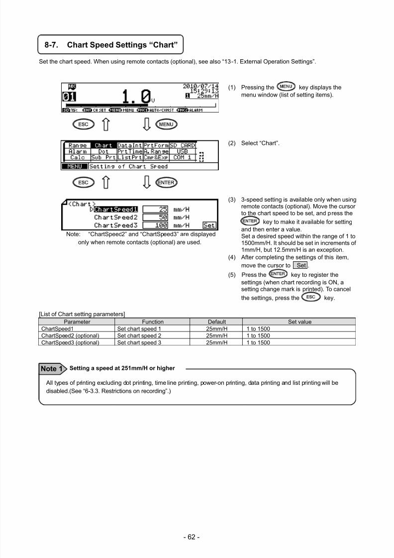
7/23/2019 AH4000 Multi General INE-851B (1)
http://slidepdf.com/reader/full/ah4000-multi-general-ine-851b-1 65/121
- 62 -
8-7. Chart Speed Settings “Chart”
Set the chart speed. When using remote contacts (optional), see also “13-1. External Operation Settings”.
(1) Pressing the key displays the
menu window (list of setting items).
(2) Select “Chart”.
(3) 3-speed setting is available only when usingremote contacts (optional). Move the cursorto the chart speed to be set, and press the
key to make it available for settingand then enter a value.Set a desired speed within the range of 1 to1500mm/H. It should be set in increments of1mm/H, but 12.5mm/H is an exception.
(4) After completing the settings of this item,move the cursor to Set .
(5) Press the key to register thesettings (when chart recording is ON, asetting change mark is printed). To cancel
the settings, press the key.
[List of Chart setting parameters]Parameter Function Default Set value
ChartSpeed1 Set chart speed 1 25mm/H 1 to 1500 ChartSpeed2 (optional) Set chart speed 2 25mm/H 1 to 1500 ChartSpeed3 (optional) Set chart speed 3 25mm/H 1 to 1500
Note: “ChartSpeed2” and “ChartSpeed3” are displayedonly when remote contacts (optional) are used.
All types of printing excluding dot printing, time line printing, power-on printing, data printing and list printing will be
disabled.(See “6-3.3. Restrictions on recording”.)
Setting a speed at 251mm/H or higher Note 1
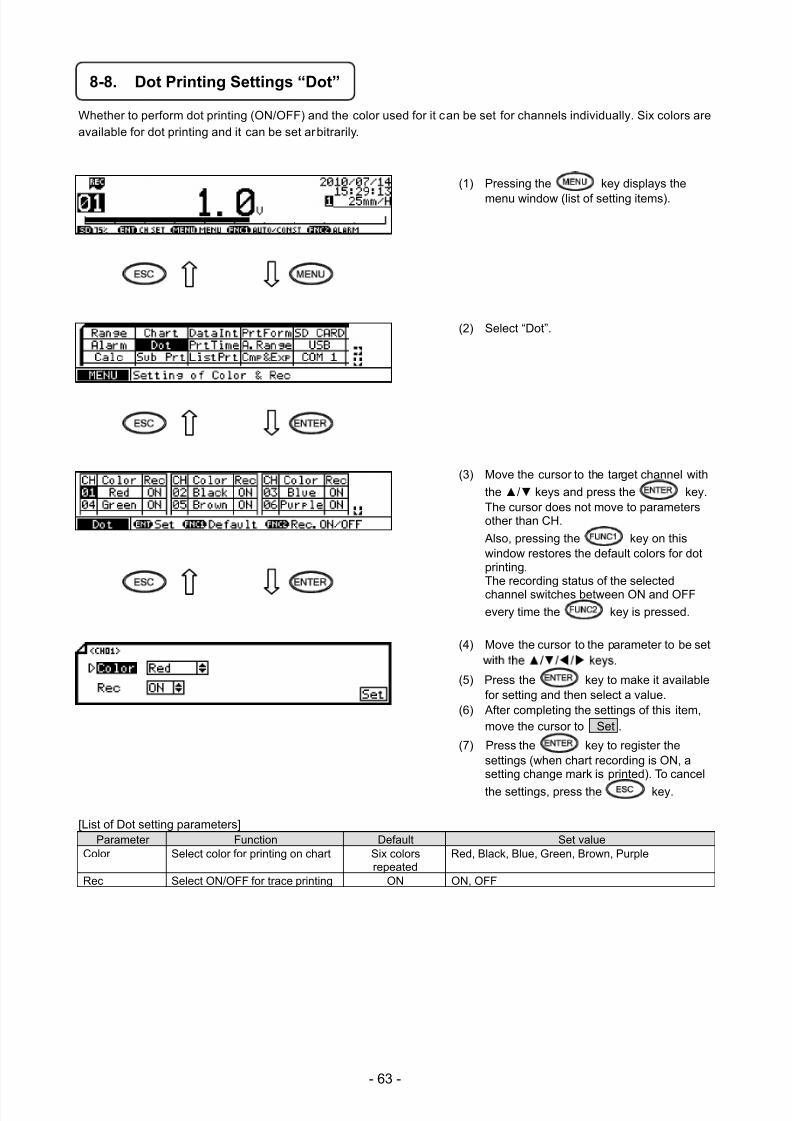
7/23/2019 AH4000 Multi General INE-851B (1)
http://slidepdf.com/reader/full/ah4000-multi-general-ine-851b-1 66/121
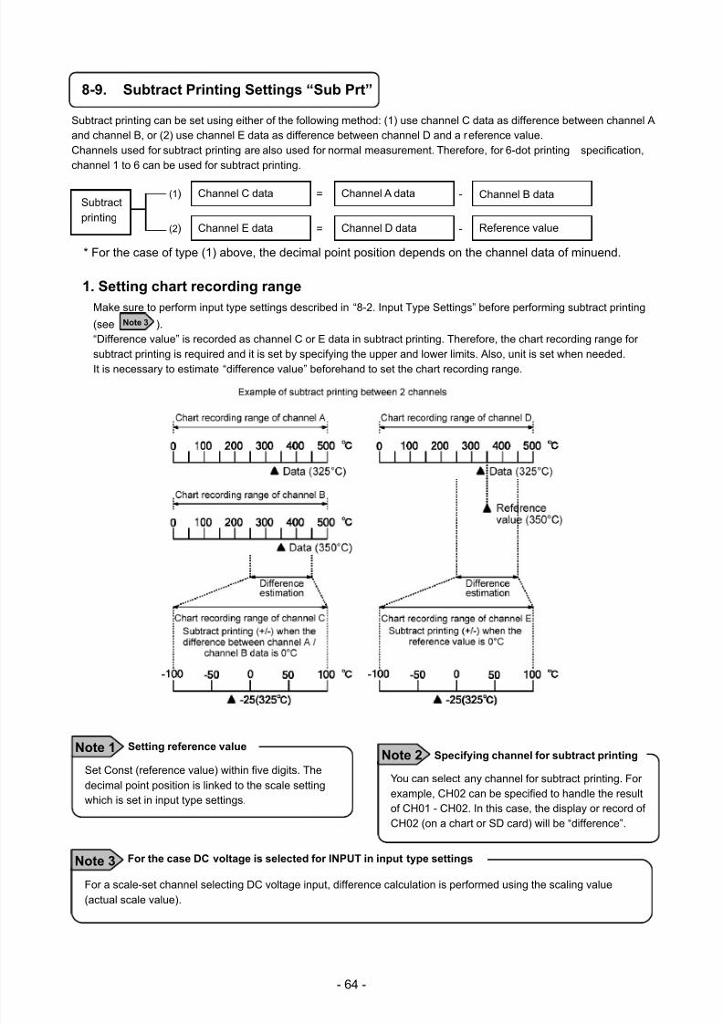
7/23/2019 AH4000 Multi General INE-851B (1)
http://slidepdf.com/reader/full/ah4000-multi-general-ine-851b-1 67/121
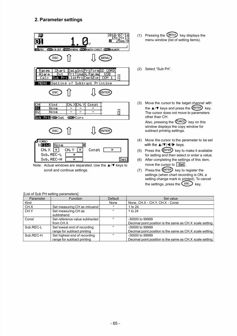
7/23/2019 AH4000 Multi General INE-851B (1)
http://slidepdf.com/reader/full/ah4000-multi-general-ine-851b-1 68/121
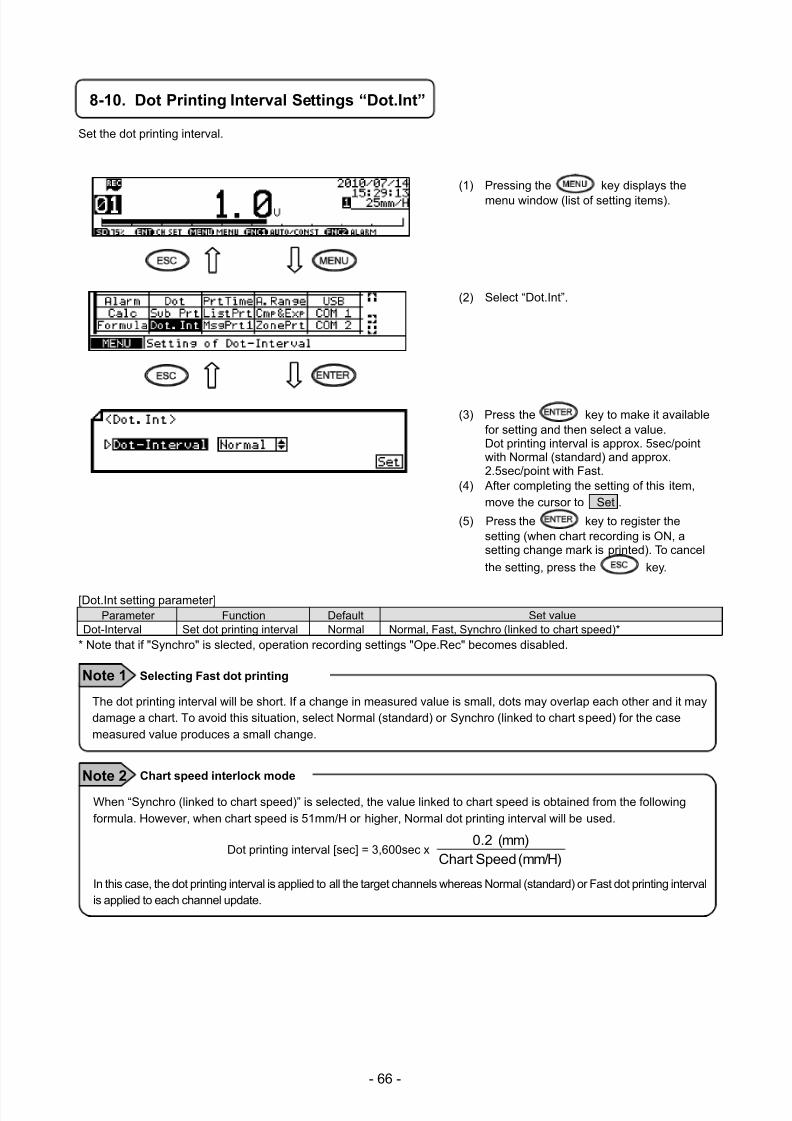
7/23/2019 AH4000 Multi General INE-851B (1)
http://slidepdf.com/reader/full/ah4000-multi-general-ine-851b-1 69/121
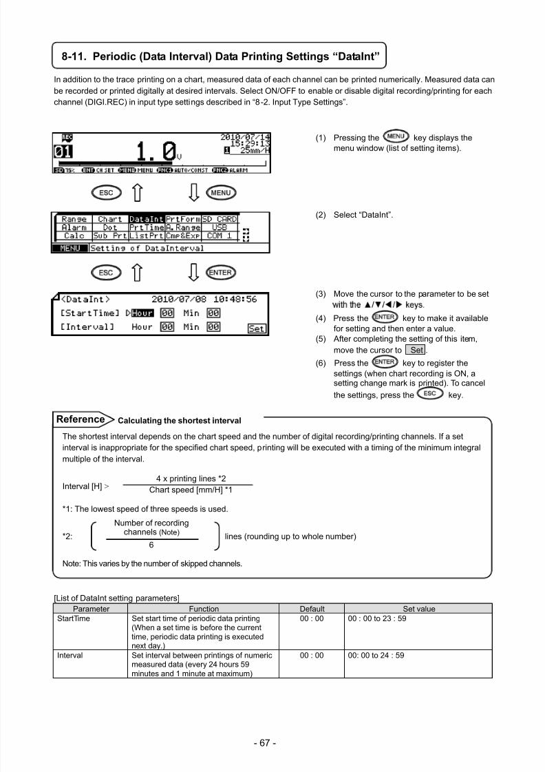
7/23/2019 AH4000 Multi General INE-851B (1)
http://slidepdf.com/reader/full/ah4000-multi-general-ine-851b-1 70/121
- 67 -
8-11. Periodic (Data Interval) Data Printing Settings “DataInt”
In addition to the trace printing on a chart, measured data of each channel can be printed numerically. Measured data canbe recorded or printed digitally at desired intervals. Select ON/OFF to enable or disable digital recording/printing for eachchannel (DIGI.REC) in input type settings described in “8-2. Input Type Settings”.
(1) Pressing the key displays themenu window (list of setting items).
(2) Select “DataInt”.
(3) Move the cursor to the parameter to be set
(4) Press the key to make it availablefor setting and then enter a value.
(5) After completing the setting of this item,move the cursor to Set .
(6) Press the key to register thesettings (when chart recording is ON, asetting change mark is printed). To cancel
the settings, press the key.
[List of DataInt setting parameters]Parameter Function Default Set value
StartTime Set start time of periodic data printing(When a set time is before the currenttime, periodic data printing is executednext day.)
00 : 00 00 : 00 to 23 : 59
Interval Set interval between printings of numericmeasured data (every 24 hours 59
minutes and 1 minute at maximum)
00 : 00 00: 00 to 24 : 59
The shortest interval depends on the chart speed and the number of digital recording/printing channels. If a setinterval is inappropriate for the specified chart speed, printing will be executed with a timing of the minimum integralmultiple of the interval.
Interval [H] >
*1: The lowest speed of three speeds is used.
*2: lines (rounding up to whole number)
Note: This varies by the number of skipped channels.
記録チャンネル数 (注)
6
Calculating the shortest interval Reference
4 x printing lines *2Chart speed [mm/H] *1
Number of recordingchannels (Note)
6
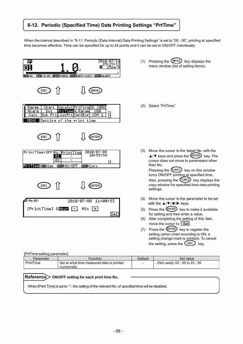
7/23/2019 AH4000 Multi General INE-851B (1)
http://slidepdf.com/reader/full/ah4000-multi-general-ine-851b-1 71/121
- 68 -
8-12. Periodic (Specified Time) Data Printing Settings “PrtTime”
When the interval described in “8-11. Periodic (Data Interval) Data Printing Settings” is set to “00 : 00”, printing at specifiedtime becomes effective. Time can be specified for up to 24 points and it can be set to ON/OFF individually.
(1) Pressing the key displays themenu window (list of setting items).
(2) Select “PrtTime”.
(3) Move the cursor to the target No. with the
/ keys and press the key. Thecursor does not move to parameters otherthan No.
Pressing the key on this windowturns ON/OFF printing at specified time.
Also, pressing the key displays thecopy window for specified time data printingsettings.
(4) Move the cursor to the parameter to be set
(5) Press the key to make it availablefor setting and then enter a value.
(6) After completing the setting of this item,move the cursor to Set .
(7) Press the key to register thesetting (when chart recording is ON, asetting change mark is printed). To cancel
the setting, press the key.
[PrtTime setting parameter]Parameter Function Default Set value
PrintTime Set at what time measured data is printednumerically
- - (Not used), 00 : 00 to 23 : 59
When [Print Time] is set to “-“, the setting of the relevant No. of specified time will be disabled.
ON/OFF setting for each print time No. Reference
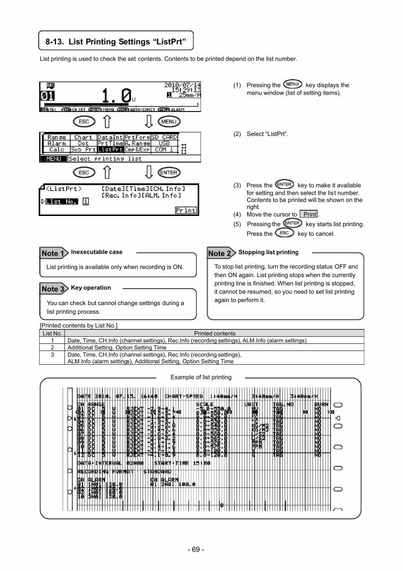
7/23/2019 AH4000 Multi General INE-851B (1)
http://slidepdf.com/reader/full/ah4000-multi-general-ine-851b-1 72/121
- 69 -
8-13. List Printing Settings “ListPrt”
List printing is used to check the set contents. Contents to be printed depend on the list number.
(1) Pressing the key displays themenu window (list of setting items).
(2) Select “ListPrt”.
(3) Press the key to make it availablefor setting and then select the list number.
Contents to be printed will be shown on theright.(4) Move the cursor to Print .
(5) Pressing the key starts list printing.
Press the key to cancel.
[Printed contents by List No.]
List No. Printed contents 1 Date, Time, CH.Info (channel settings), Rec.Info (recording settings), ALM.Info (alarm settings) 2 Additional Setting, Option Setting Time 3 Date, Time, CH.Info (channel settings), Rec.Info (recording settings),
ALM.Info (alarm settings), Additional Setting, Option Setting Time
Example of list printing
To stop list printing, turn the recording status OFF andthen ON again. List printing stops when the currentlyprinting line is finished. When list printing is stopped,it cannot be resumed, so you need to set list printing
again to perform it.
Stopping list printing Note 2
You can check but cannot change settings during alist printing process.
Key operationNote 3
List printing is available only when recording is ON.
Inexecutable case Note 1
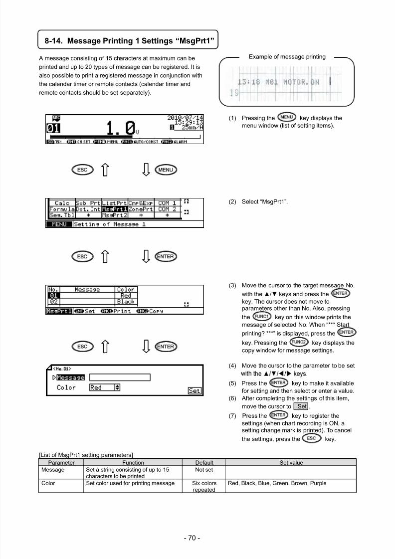
7/23/2019 AH4000 Multi General INE-851B (1)
http://slidepdf.com/reader/full/ah4000-multi-general-ine-851b-1 73/121
- 70 -
8-14. Message Printing 1 Settings “MsgPrt1”
A message consisting of 15 characters at maximum can be
printed and up to 20 types of message can be registered. It is
also possible to print a registered message in conjunction with
the calendar timer or remote contacts (calendar timer and
remote contacts should be set separately).
(1) Pressing the key displays themenu window (list of setting items).
(2) Select “MsgPrt1”.
(3) Move the cursor to the target message No.
with the / keys and press thekey. The cursor does not move toparameters other than No. Also, pressing
the key on this window prints themessage of selected No. When “*** Start
printing? ***” is displayed, press the
key. Pressing the key displays thecopy window for message settings.
(4) Move the cursor to the parameter to be set
(5) Press the key to make it available
for setting and then select or enter a value.(6) After completing the settings of this item,move the cursor to Set .
(7) Press the key to register thesettings (when chart recording is ON, asetting change mark is printed). To cancel
the settings, press the key.
[List of MsgPrt1 setting parameters]
Parameter Function Default Set valueMessage Set a string consisting of up to 15
characters to be printedNot set
Color Set color used for printing message Six colors
repeated
Red, Black, Blue, Green, Brown, Purple
Example of message printing
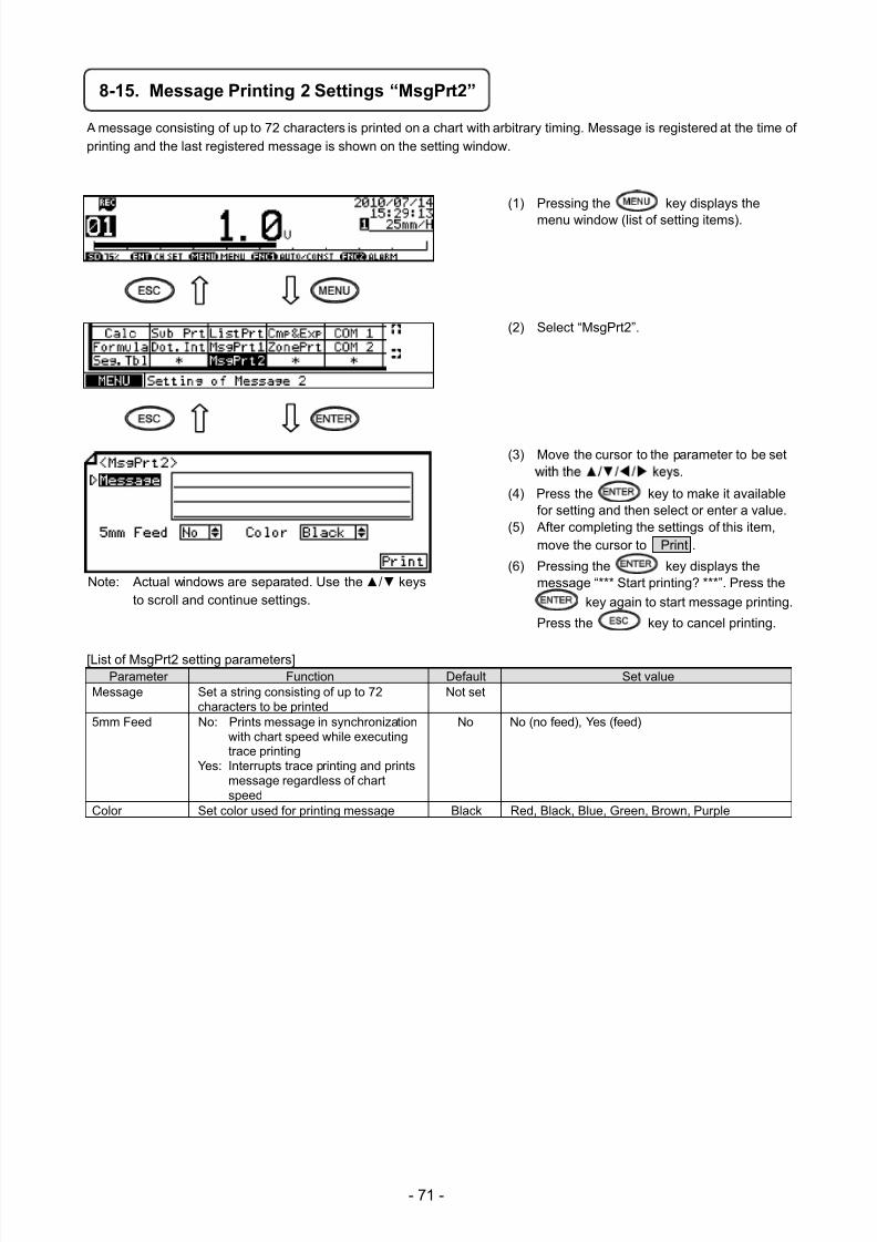
7/23/2019 AH4000 Multi General INE-851B (1)
http://slidepdf.com/reader/full/ah4000-multi-general-ine-851b-1 74/121
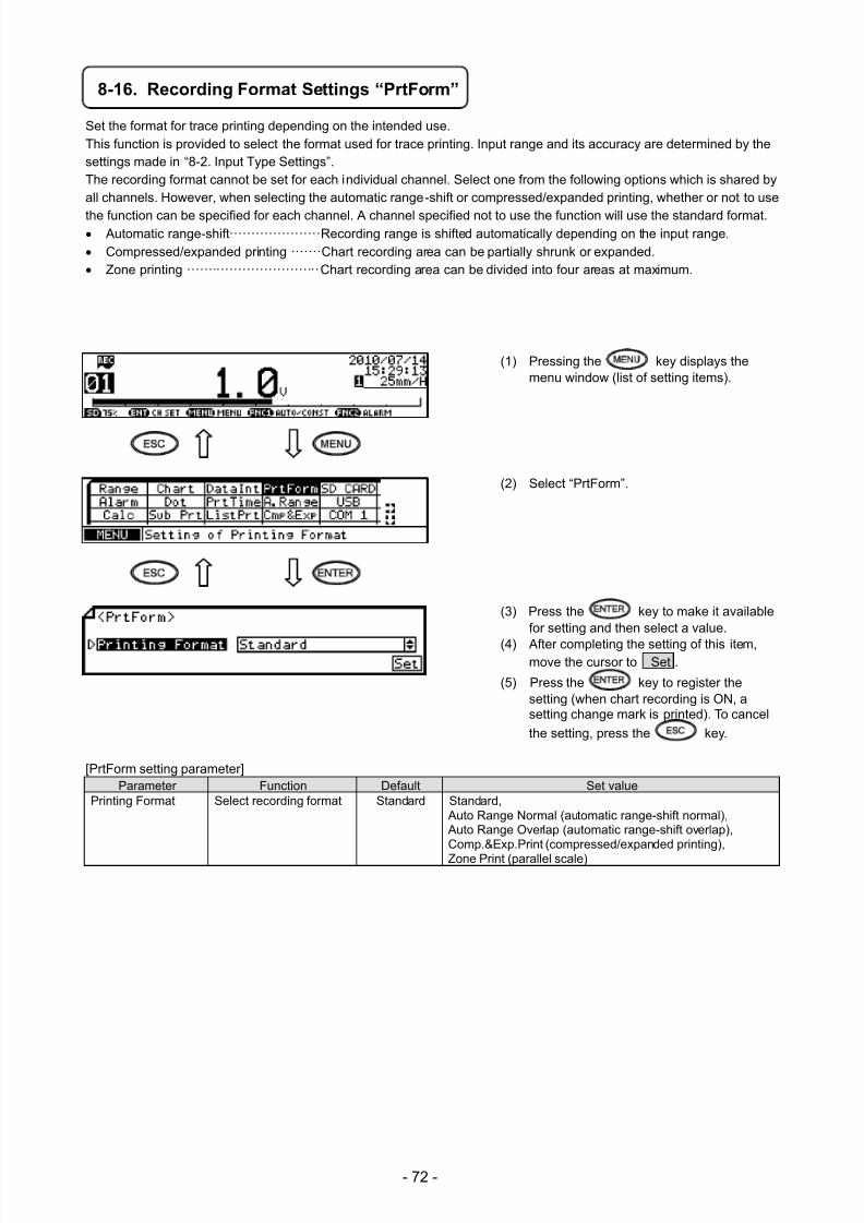
7/23/2019 AH4000 Multi General INE-851B (1)
http://slidepdf.com/reader/full/ah4000-multi-general-ine-851b-1 75/121
- 72 -
8-16. Recording Format Settings “PrtForm”
Set the format for trace printing depending on the intended use.This function is provided to select the format used for trace printing. Input range and its accuracy are determined by thesettings made in “8-2. Input Type Settings”.The recording format cannot be set for each individual channel. Select one from the following options which is shared byall channels. However, when selecting the automatic range-shift or compressed/expanded printing, whether or not to use
the function can be specified for each channel. A channel specified not to use the function will use the standard format.
Automatic range-shift ····················· Recording range is shifted automatically depending on the input range. Compressed/expanded printing ······· Chart recording area can be partially shrunk or expanded. Zone printing ······························· Chart recording area can be divided into four areas at maximum.
(1) Pressing the key displays themenu window (list of setting items).
(2) Select “PrtForm”.
(3) Press the key to make it availablefor setting and then select a value.
(4) After completing the setting of this item,move the cursor to Set .
(5) Press the key to register thesetting (when chart recording is ON, asetting change mark is printed). To cancel
the setting, press the key.
[PrtForm setting parameter]
Parameter Function Default Set valuePrinting Format Select recording format Standard Standard,
Auto Range Normal (automatic range-shift normal), Auto Range Overlap (automatic range-shift overlap),Comp.&Exp.Print (compressed/expanded printing),
Zone Print (parallel scale)
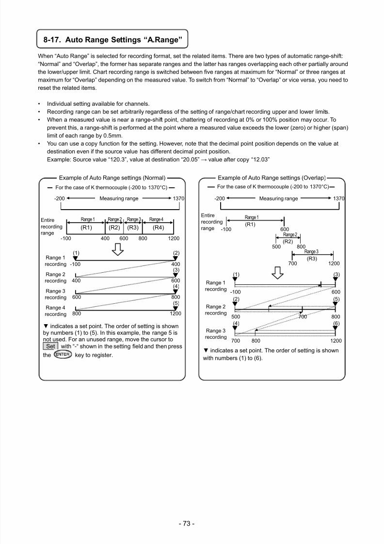
7/23/2019 AH4000 Multi General INE-851B (1)
http://slidepdf.com/reader/full/ah4000-multi-general-ine-851b-1 76/121
- 73 -
8-17. Auto Range Settings “A.Range”
When “Auto Range” is selected for recording format, set the related items. There are two types of automatic range-shift:“Normal” and “Overlap”, the former has separate ranges and the latter has ranges overlapping each other partially aroundthe lower/upper limit. Chart recording range is switched between five ranges at maximum for “Normal” or three ranges atmaximum for “Overlap” depending on the measured value. To switch from “Normal” to “Overlap” or vice versa, you need toreset the related items.
• Individual setting available for channels.• Recording range can be set arbitrarily regardless of the setting of range/chart recording upper and lower limits.• When a measured value is near a range-shift point, chattering of recording at 0% or 100% position may occur. To
prevent this, a range-shift is performed at the point where a measured value exceeds the lower (zero) or higher (span)limit of each range by 0.5mm.
• You can use a copy function for the setting. However, note that the decimal point position depends on the value atdestination even if the source value has different decimal point position.Example: Source value “120.3”, value at destination “20.05” → value after copy “12.03”
indicates a set point. The order of setting is shownby numbers (1) to (5). In this example, the range 5 isnot used. For an unused range, move the cursor toSet with “-“ shown in the setting field and then press
the key to register.
-200 1370
Entirerecordingrange
(R1)
Range 1 Range 2 Range 3 Range 4
-100 400 600 800 1200
(R2) (R3) (R4)
Measuring range
(1) (2)
-100 400
400 600
600 800
800 1200
Range 1recording
Range 2recording
Range 3recording
Range 4recording
(3)
(4)
(5)
Example of Auto Range settings (Normal)
For the case of K thermocouple (-200 to 1370°C)
indicates a set point. The order of setting is shownwith numbers (1) to (6).
Example of Auto Range settings (Overlap)
-200 1370
Entirerecordingrange
(R1)Range 1
-100 600
Measuring range
Range 2
500 800(R2)
Range 3
700 1200(R3)
(1)
-100 600
Range 1recording
500 800
Range 2recording
1200
Range 3recording
700
700
800
(2)
(3)
(4)
(5)
(6)
For the case of K thermocouple (-200 to 1370°C)
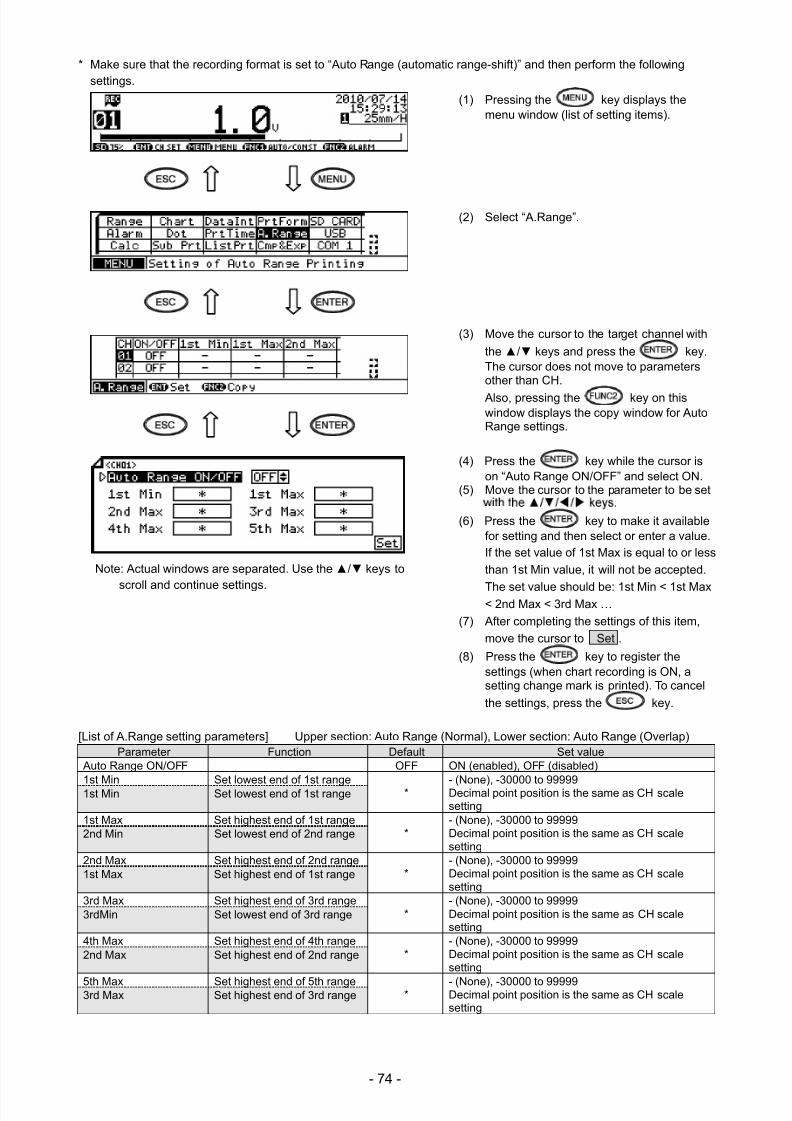
7/23/2019 AH4000 Multi General INE-851B (1)
http://slidepdf.com/reader/full/ah4000-multi-general-ine-851b-1 77/121
- 74 -
* Make sure that the recording format is set to “Auto Range (automatic range-shift)” and then perform the followingsettings.
(1) Pressing the key displays themenu window (list of setting items).
(2) Select “A.Range”.
(3) Move the cursor to the target channel with
the / keys and press the key.The cursor does not move to parametersother than CH.
Also, pressing the key on thiswindow displays the copy window for AutoRange settings.
(4) Press the key while the cursor ison “Auto Range ON/OFF” and select ON.
(5) Move the cursor to the parameter to be set
(6) Press the key to make it availablefor setting and then select or enter a value.If the set value of 1st Max is equal to or less
than 1st Min value, it will not be accepted.
The set value should be: 1st Min < 1st Max< 2nd Max < 3rd Max …
(7) After completing the settings of this item,
move the cursor to Set .
(8) Press the key to register thesettings (when chart recording is ON, asetting change mark is printed). To cancel
the settings, press the key.
[List of A.Range setting parameters] Upper section: Auto Range (Normal), Lower section: Auto Range (Overlap) Parameter Function Default Set value
Auto Range ON/OFF OFF ON (enabled), OFF (disabled)
1st Min Set lowest end of 1st range * - (None), -30000 to 99999Decimal point position is the same as CH scalesetting
1st Min Set lowest end of 1st range
1st Max Set highest end of 1st range*
- (None), -30000 to 99999Decimal point position is the same as CH scalesetting
2nd Min Set lowest end of 2nd range
2nd Max Set highest end of 2nd range*
- (None), -30000 to 99999Decimal point position is the same as CH scalesetting
1st Max Set highest end of 1st range
3rd Max Set highest end of 3rd range*
- (None), -30000 to 99999Decimal point position is the same as CH scalesetting
3rdMin Set lowest end of 3rd range
4th Max Set highest end of 4th range*
- (None), -30000 to 99999Decimal point position is the same as CH scalesetting
2nd Max Set highest end of 2nd range
5th Max Set highest end of 5th range * - (None), -30000 to 99999Decimal point position is the same as CH scalesetting
3rd Max Set highest end of 3rd range
Note: Actual windows are separated. Use the / keys to
scroll and continue settings.
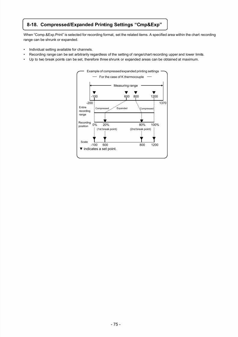
7/23/2019 AH4000 Multi General INE-851B (1)
http://slidepdf.com/reader/full/ah4000-multi-general-ine-851b-1 78/121
- 75 -
8-18. Compressed/Expanded Printing Settings “Cmp&Exp”
When “Comp.&Exp.Print” is selected for recording format, set the related items. A specified area within the chart recordingrange can be shrunk or expanded.
• Individual setting available for channels.• Recording range can be set arbitrarily regardless of the setting of range/chart recording upper and lower limits.
• Up to two break points can be set, therefore three shrunk or expanded areas can be obtained at maximum.
indicates a set point.
Example of compressed/expanded printing settings
Entirerecordingrange
Scale
(1st break point) (2nd break point)
Compressed Expanded Compressed
Recordingposition
-200 1370
-100 600 800 1200
0% 100%20% 80%
-100 600 800 1200
For the case of K thermocouple
Measuring range
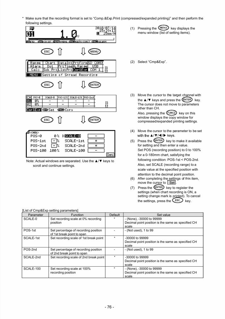
7/23/2019 AH4000 Multi General INE-851B (1)
http://slidepdf.com/reader/full/ah4000-multi-general-ine-851b-1 79/121
- 76 -
* Make sure that the recording format is set to “Comp.&Exp.Print (compressed/expanded printing)” and then perform thefollowing settings.
(1) Pressing the key displays themenu window (list of setting items).
(2) Select “Cmp&Exp”.
(3) Move the cursor to the target channel with
the / keys and press the key.The cursor does not move to parametersother than CH.
Also, pressing the key on thiswindow displays the copy window forcompressed/expanded printing settings.
(4) Move the cursor to the parameter to be set
(5) Press the key to make it availablefor setting and then enter a value.Set POS (recording position) to 0 to 100%
for a 0-180mm chart, satisfying the
following condition: POS-1st < POS-2nd.
Also, set SCALE (recording range) to a
scale value at the specified position withattention to the decimal point position.
(6) After completing the settings of this item,move the cursor to Set .
(7) Press the key to register thesettings (when chart recording is ON, asetting change mark is printed). To cancel
the settings, press the key.
[List of Cmp&Exp setting parameters]
Parameter Function Default Set valueSCALE-0 Set recording scale at 0% recording
position
* - (None), -30000 to 99999
Decimal point position is the same as specified CHscalePOS-1st Set percentage of recording position
of 1st break point to span- - (Not used), 1 to 99
SCALE-1st Set recording scale of 1st break point * -30000 to 99999 Decimal point position is the same as specified CHscale
POS-2nd Set percentage of recording positionof 2nd break point to span
- - (Not used), 1 to 99
SCALE-2nd Set recording scale of 2nd break point * -30000 to 99999
Decimal point position is the same as specified CHscale
SCALE-100 Set recording scale at 100%recording position
* - (None), -30000 to 99999 Decimal point position is the same as specified CHscale
Note: Actual windows are separated. Use the / keys toscroll and continue settings.
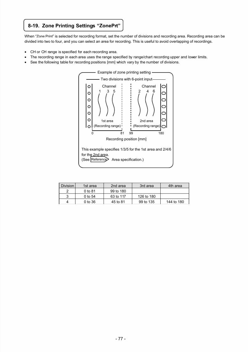
7/23/2019 AH4000 Multi General INE-851B (1)
http://slidepdf.com/reader/full/ah4000-multi-general-ine-851b-1 80/121
- 77 -
8-19. Zone Printing Settings “ZonePrt”
When “Zone Print” is selected for recording format, set the number of divisions and recording area. Recording area can bedivided into two to four, and you can select an area for recording. This is useful to avoid overlapping of recordings.
CH or CH range is specified for each recording area. The recording range in each area uses the range specified by range/chart recording upper and lower limits. See the following table for recording positions [mm] which vary by the number of divisions.
Division 1st area 2nd area 3rd area 4th area2 0 to 81 99 to 180
3 0 to 54 63 to 117 126 to 180
4 0 to 36 45 to 81 99 to 135 144 to 180
Recording position [mm]
This example specifies 1/3/5 for the 1st area and 2/4/6
for the 2nd area.(See Area specification.)
Example of zone printing setting
Channel1 3 5
Channel2 4 6
1st area
(Recording range)
2nd area
(Recording range)
0 81 99 180
Reference
Two divisions with 6-point input
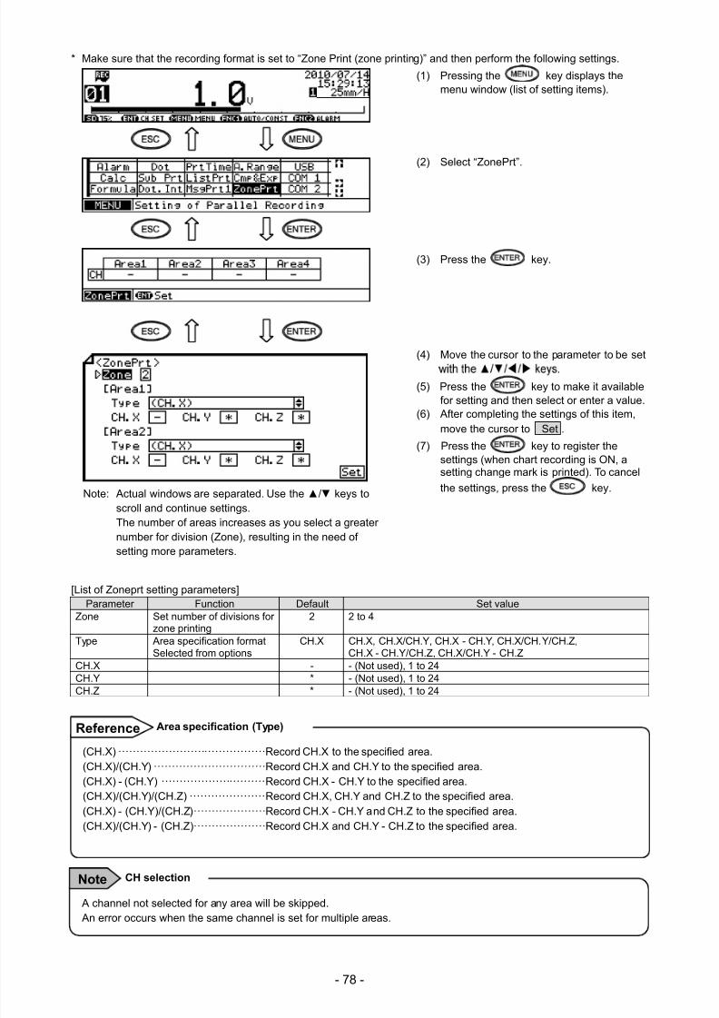
7/23/2019 AH4000 Multi General INE-851B (1)
http://slidepdf.com/reader/full/ah4000-multi-general-ine-851b-1 81/121
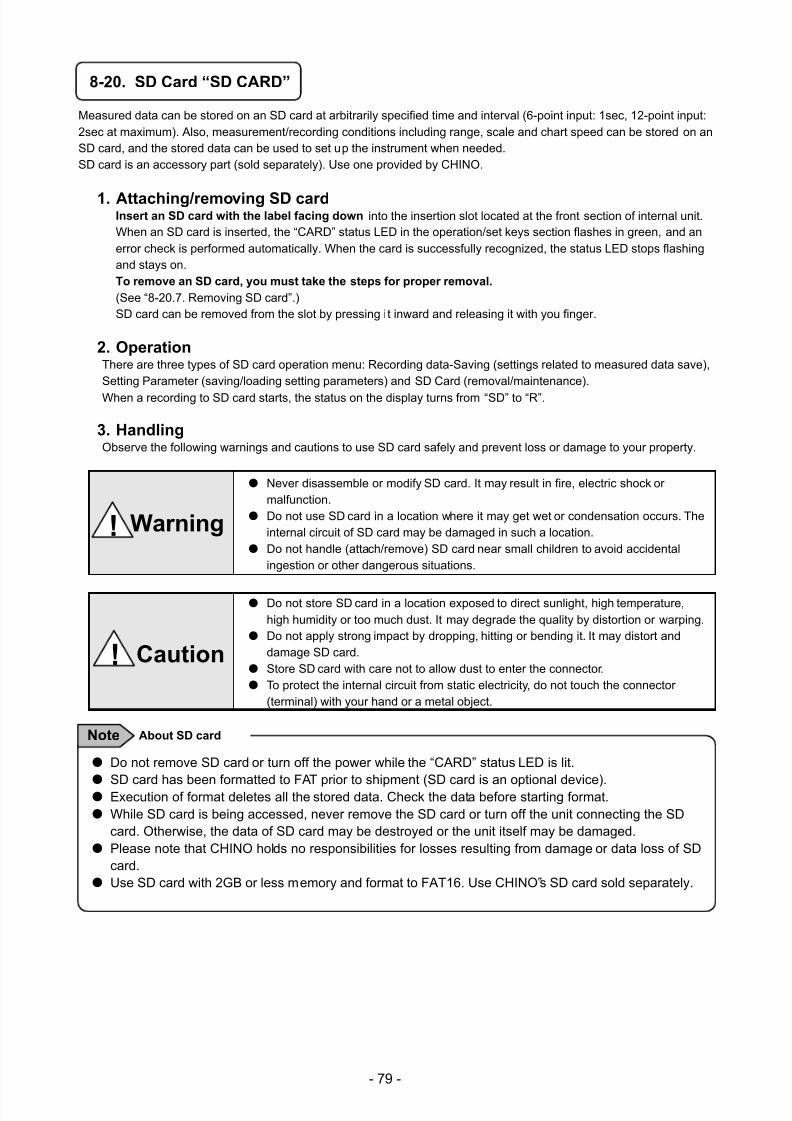
7/23/2019 AH4000 Multi General INE-851B (1)
http://slidepdf.com/reader/full/ah4000-multi-general-ine-851b-1 82/121
- 79 -
8-20. SD Card “SD CARD”
Measured data can be stored on an SD card at arbitrarily specified time and interval (6-point input: 1sec, 12-point input:2sec at maximum). Also, measurement/recording conditions including range, scale and chart speed can be stored on anSD card, and the stored data can be used to set up the instrument when needed.SD card is an accessory part (sold separately). Use one provided by CHINO.
1. Attaching/removing SD card
Insert an SD card with the label facing down into the insertion slot located at the front section of internal unit.When an SD card is inserted, the “CARD” status LED in the operation/set keys section flashes in green, and anerror check is performed automatically. When the card is successfully recognized, the status LED stops flashingand stays on.To remove an SD card, you must take the steps for proper removal.
(See “8-20.7. Removing SD card”.)SD card can be removed from the slot by pressing it inward and releasing it with you finger.
2. Operation There are three types of SD card operation menu: Recording data-Saving (settings related to measured data save),Setting Parameter (saving/loading setting parameters) and SD Card (removal/maintenance).
When a recording to SD card starts, the status on the display turns from “SD” to “R”.
3. Handling Observe the following warnings and cautions to use SD card safely and prevent loss or damage to your property.
Never disassemble or modify SD card. It may result in fire, electric shock ormalfunction.
Do not use SD card in a location where it may get wet or condensation occurs. Theinternal circuit of SD card may be damaged in such a location.
Do not handle (attach/remove) SD card near small children to avoid accidentalingestion or other dangerous situations.
Do not store SD card in a location exposed to direct sunlight, high temperature,high humidity or too much dust. It may degrade the quality by distortion or warping.
Do not apply strong impact by dropping, hitting or bending it. It may distort anddamage SD card.
Store SD card with care not to allow dust to enter the connector.
To protect the internal circuit from static electricity, do not touch the connector(terminal) with your hand or a metal object.
! Warning
! Caution
Do not remove SD card or turn off the power while the “CARD” status LED is lit.
SD card has been formatted to FAT prior to shipment (SD card is an optional device). Execution of format deletes all the stored data. Check the data before starting format. While SD card is being accessed, never remove the SD card or turn off the unit connecting the SD
card. Otherwise, the data of SD card may be destroyed or the unit itself may be damaged. Please note that CHINO holds no responsibilities for losses resulting from damage or data loss of SD
card. Use SD card with 2GB or less memory and format to FAT16. Use CHINO‟s SD card sold separately.
About SD card Note
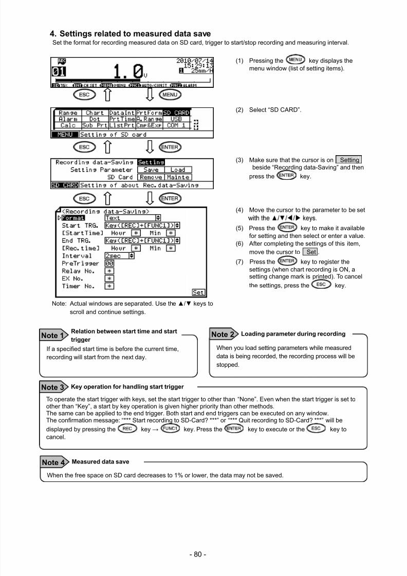
7/23/2019 AH4000 Multi General INE-851B (1)
http://slidepdf.com/reader/full/ah4000-multi-general-ine-851b-1 83/121
- 80 -
4. Settings related to measured data saveSet the format for recording measured data on SD card, trigger to start/stop recording and measuring interval.
(1) Pressing the key displays themenu window (list of setting items).
(2) Select “SD CARD”.
(3) Make sure that the cursor is on Settingbeside “Recording data-Saving” and then
press the key.
(4) Move the cursor to the parameter to be set
(5) Press the key to make it availablefor setting and then select or enter a value.
(6) After completing the settings of this item,move the cursor to Set .
(7) Press the key to register thesettings (when chart recording is ON, asetting change mark is printed). To cancel
the settings, press the key.
To operate the start trigger with keys, set the start trigger to other than “None”. Even when the start trigger is set toother than “Key”, a start by key operation is given higher priority than other methods.The same can be applied to the end trigger. Both start and end triggers can be executed on any window.The confirmation message: “*** Start recording to SD-Card? ***” or “*** Quit recording to SD-Card? ***” will be
displayed by pressing the key → key. Press the key to execute or the key tocancel.
Key operation for handling start trigger Note 3
Note: Actual windows are separated. Use the / keys toscroll and continue settings.
If a specified start time is before the current time,recording will start from the next day.
Relation between start time and start
trigger Note 1
When you load setting parameters while measureddata is being recorded, the recording process will bestopped.
Loading parameter during recording Note 2
When the free space on SD card decreases to 1% or lower, the data may not be saved.
Measured data save Note 4
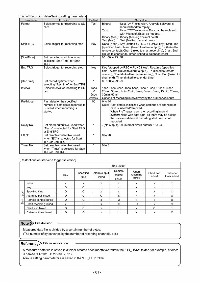
7/23/2019 AH4000 Multi General INE-851B (1)
http://slidepdf.com/reader/full/ah4000-multi-general-ine-851b-1 84/121
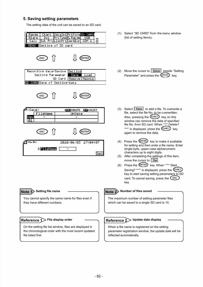
7/23/2019 AH4000 Multi General INE-851B (1)
http://slidepdf.com/reader/full/ah4000-multi-general-ine-851b-1 85/121
- 82 -
5. Saving setting parameters
The setting data of the unit can be saved to an SD card.
(1) Select “SD CARD” from the menu window(list of setting items).
(2) Move the cursor to Save beside “Setting
Parameter” and press the key.
(3) Select New to add a file. To overwrite afile, select the file No. to be overwritten.
Also, pressing the key on thiswindow can remove the data of specifiedfile No. from SD card. When “*** Delete?
***” is displayed, press the keyagain to remove the data.
(4) Press the key to make it availablefor setting and then enter a file name. Entersingle-byte, upper-case alphanumericcharacters up to eight digits.
(5) After completing the settings of this item,move the cursor to Set .
(6) Press the key. When “*** Start
Saving? ***” is displayed, press thekey to start saving setting parameters to SD
card. To cancel saving, press thekey.
You cannot specify the same name for files even if
they have different numbers.
Setting file name Note 1
The maximum number of setting parameter files
which can be saved to a single SD card is 10.
Number of files saved Note 2
On the setting file list window, files are displayed inthe chronological order with the most recent updatedfile listed first.
File display order Reference 1
When a file name is registered on the settingparameter registration window, the update date will bereflected automatically.
Update date display Reference 2
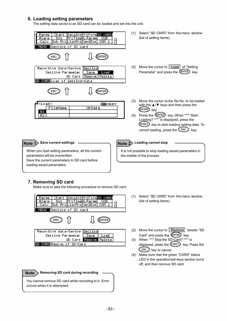
7/23/2019 AH4000 Multi General INE-851B (1)
http://slidepdf.com/reader/full/ah4000-multi-general-ine-851b-1 86/121
- 83 -
6. Loading setting parametersThe setting data saved to an SD card can be loaded and set into the unit.
(1) Select “SD CARD” from the menu window(list of setting items).
(2) Move the cursor to Load of “Setting
Parameter” and press the key.
(3) Move the cursor to the file No. to be loadedwith the / keys and then press the
key.
(4) Press the key. When “*** StartLoading? ***” is displayed, press the
key to start loading setting data. To
cancel loading, press the key.
7. Removing SD cardMake sure to take the following procedure to remove SD card.
(1) Select “SD CARD” from the menu window(list of setting items).
(2) Move the cursor to Remove beside “SD
Card” and press the key.(3) When “*** Stop the SD-Card? ***” is
displayed, press the key. Press the
key to cancel.(4) Make sure that the green “CARD” status
LED in the operation/set keys section turnsoff, and then remove SD card.
When you load setting parameters, all the currentparameters will be overwritten.Save the current parameters to SD card beforeloading saved parameters.
Save current settings Note 1
It is not possible to stop loading saved parameters inthe middle of the process.
Loading cannot stop Note 2
You cannot remove SD card while recording to it. Erroroccurs when it is attempted.
Removing SD card during recording Note
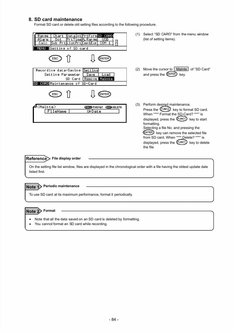
7/23/2019 AH4000 Multi General INE-851B (1)
http://slidepdf.com/reader/full/ah4000-multi-general-ine-851b-1 87/121
- 84 -
8. SD card maintenanceFormat SD card or delete old setting files according to the following procedure.
(1) Select “SD CARD” from the menu window(list of setting items).
(2) Move the cursor to Mainte of “SD Card”
and press the key.
(3) Perform desired maintenance.
Press the key to format SD card.When “*** Format the SD-Card? ***” is
displayed, press the key to startformatting.Selecting a file No. and pressing the
key can remove the selected filefrom SD card. When “*** Delete? ***” is
displayed, press the key to deletethe file.
On the setting file list window, files are displayed in the chronological order with a file having the oldest update datelisted first.
File display order Reference
To use SD card at its maximum performance, format it periodically.
Periodic maintenance Note 1
Note that all the data saved on an SD card is deleted by formatting. You cannot format an SD card while recording.
Format Note 2
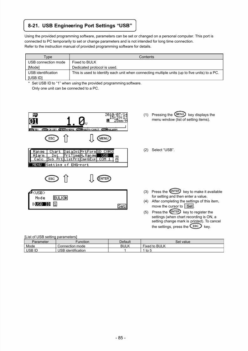
7/23/2019 AH4000 Multi General INE-851B (1)
http://slidepdf.com/reader/full/ah4000-multi-general-ine-851b-1 88/121
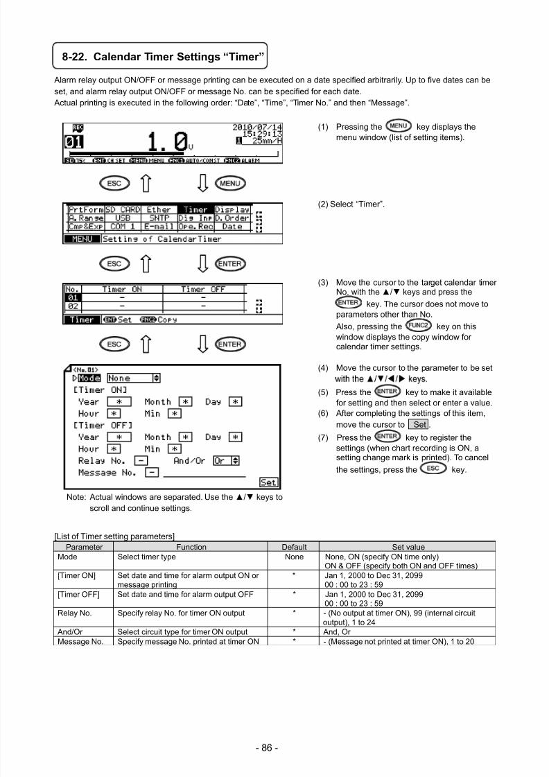
7/23/2019 AH4000 Multi General INE-851B (1)
http://slidepdf.com/reader/full/ah4000-multi-general-ine-851b-1 89/121
- 86 -
8-22. Calendar Timer Settings “Timer”
Alarm relay output ON/OFF or message printing can be executed on a date specified arbitrarily. Up to five dates can beset, and alarm relay output ON/OFF or message No. can be specified for each date. Actual printing is executed in the following order: “Date”, “Time”, “Timer No.” and then “Message”.
(1) Pressing the key displays the
menu window (list of setting items).
(2) Select “Timer”.
(3) Move the cursor to the target calendar timerNo. with the / keys and press the
key. The cursor does not move toparameters other than No.
Also, pressing the key on thiswindow displays the copy window forcalendar timer settings.
(4) Move the cursor to the parameter to be set
(5) Press the key to make it availablefor setting and then select or enter a value.
(6) After completing the settings of this item,move the cursor to Set .
(7) Press the key to register thesettings (when chart recording is ON, asetting change mark is printed). To cancel
the settings, press the key.
[List of Timer setting parameters]
Parameter Function Default Set valueMode Select timer type None None, ON (specify ON time only)
ON & OFF (specify both ON and OFF times)[Timer ON] Set date and time for alarm output ON or
message printing* Jan 1, 2000 to Dec 31, 2099
00 : 00 to 23 : 59 [Timer OFF] Set date and time for alarm output OFF * Jan 1, 2000 to Dec 31, 2099
00 : 00 to 23 : 59
Relay No. Specify relay No. for timer ON output * - (No output at timer ON), 99 (internal circuitoutput), 1 to 24
And/Or Select circuit type for timer ON output * And, OrMessage No. Specify message No. printed at timer ON * - (Message not printed at timer ON), 1 to 20
Note: Actual windows are separated. Use the / keys toscroll and continue settings.
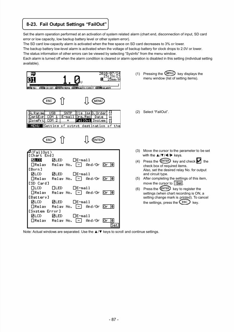
7/23/2019 AH4000 Multi General INE-851B (1)
http://slidepdf.com/reader/full/ah4000-multi-general-ine-851b-1 90/121
- 87 -
8-23. Fail Output Settings “FailOut”
Set the alarm operation performed at an activation of system related alarm (chart end, disconnection of input, SD carderror or low capacity, low backup battery level or other system error).The SD card low-capacity alarm is activated when the free space on SD card decreases to 3% or lower.
The backup battery low-level alarm is activated when the voltage of backup battery for clock drops to 2.0V or lower.The status information of other errors can be viewed by selecting “SysInfo” from the menu window.
Each alarm is turned off when the alarm condition is cleared or alarm operation is disabled in this setting (individual settingavailable).
(1) Pressing the key displays themenu window (list of setting items).
(2) Select “FailOut”.
(3) Move the cursor to the parameter to be set
(4) Press the key and check thecheck box of required items. Also, set the desired relay No. for output
and circuit type.(5) After completing the settings of this item,move the cursor to Set .
(6) Press the key to register thesettings (when chart recording is ON, asetting change mark is printed). To cancel
the settings, press the key.
Note: Actual windows are separated. Use the / keys to scroll and continue settings.
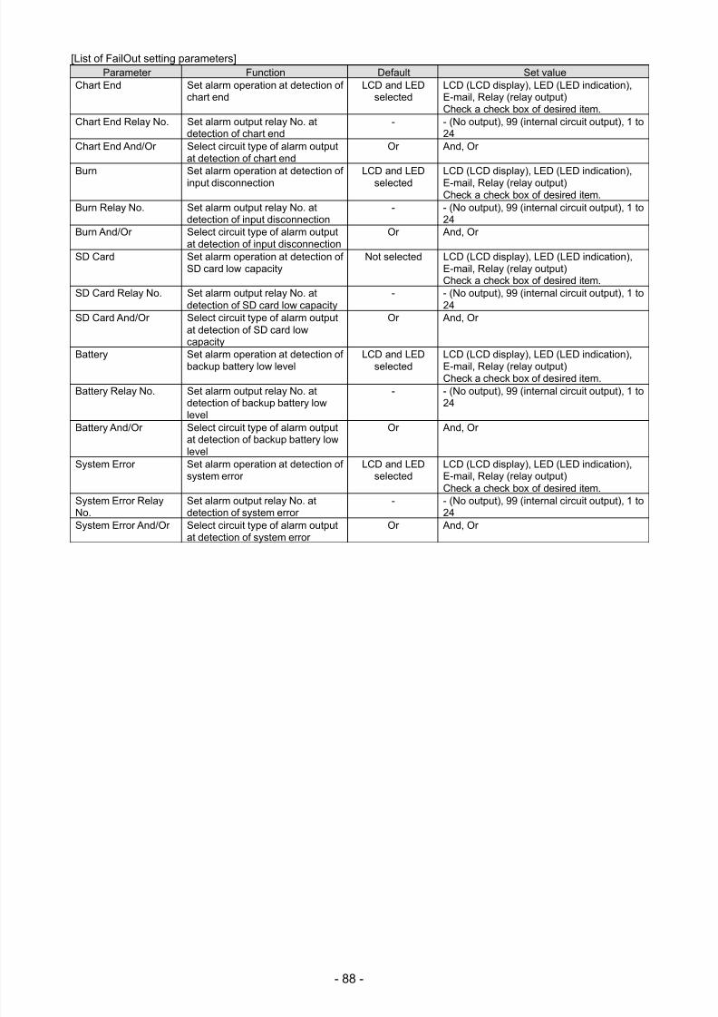
7/23/2019 AH4000 Multi General INE-851B (1)
http://slidepdf.com/reader/full/ah4000-multi-general-ine-851b-1 91/121
- 88 -
[List of FailOut setting parameters]Parameter Function Default Set value
Chart End Set alarm operation at detection ofchart end
LCD and LEDselected
LCD (LCD display), LED (LED indication),E-mail, Relay (relay output)Check a check box of desired item.
Chart End Relay No. Set alarm output relay No. atdetection of chart end
- - (No output), 99 (internal circuit output), 1 to24
Chart End And/Or Select circuit type of alarm outputat detection of chart end
Or And, Or
Burn Set alarm operation at detection ofinput disconnection
LCD and LEDselected
LCD (LCD display), LED (LED indication),E-mail, Relay (relay output)Check a check box of desired item.
Burn Relay No. Set alarm output relay No. atdetection of input disconnection
- - (No output), 99 (internal circuit output), 1 to24
Burn And/Or Select circuit type of alarm outputat detection of input disconnection
Or And, Or
SD Card Set alarm operation at detection ofSD card low capacity
Not selected LCD (LCD display), LED (LED indication),E-mail, Relay (relay output)Check a check box of desired item.
SD Card Relay No. Set alarm output relay No. atdetection of SD card low capacity
- - (No output), 99 (internal circuit output), 1 to24
SD Card And/Or Select circuit type of alarm outputat detection of SD card lowcapacity
Or And, Or
Battery Set alarm operation at detection ofbackup battery low level LCD and LEDselected LCD (LCD display), LED (LED indication),E-mail, Relay (relay output)Check a check box of desired item.
Battery Relay No. Set alarm output relay No. atdetection of backup battery lowlevel
- - (No output), 99 (internal circuit output), 1 to24
Battery And/Or Select circuit type of alarm outputat detection of backup battery lowlevel
Or And, Or
System Error Set alarm operation at detection ofsystem error
LCD and LEDselected
LCD (LCD display), LED (LED indication),E-mail, Relay (relay output)Check a check box of desired item.
System Error RelayNo.
Set alarm output relay No. atdetection of system error
- - (No output), 99 (internal circuit output), 1 to24
System Error And/Or Select circuit type of alarm output
at detection of system error
Or And, Or
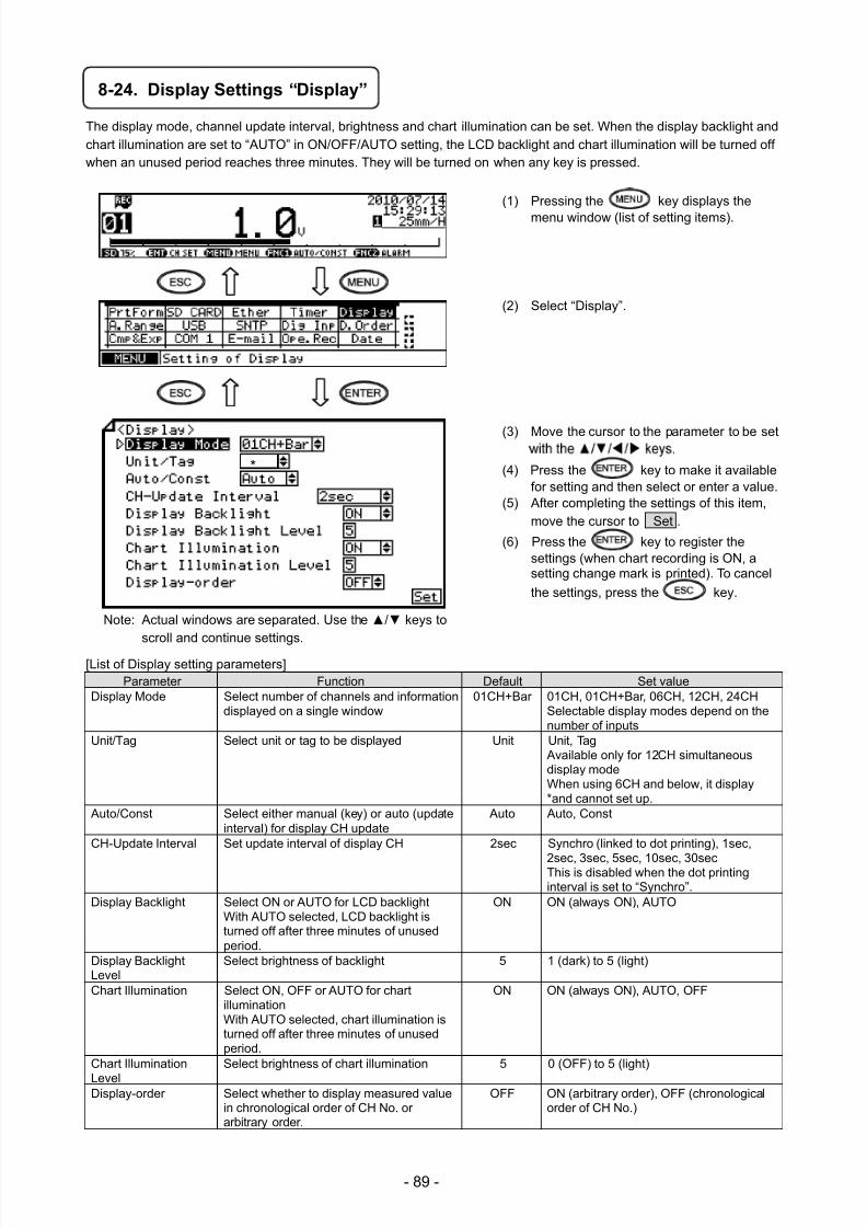
7/23/2019 AH4000 Multi General INE-851B (1)
http://slidepdf.com/reader/full/ah4000-multi-general-ine-851b-1 92/121
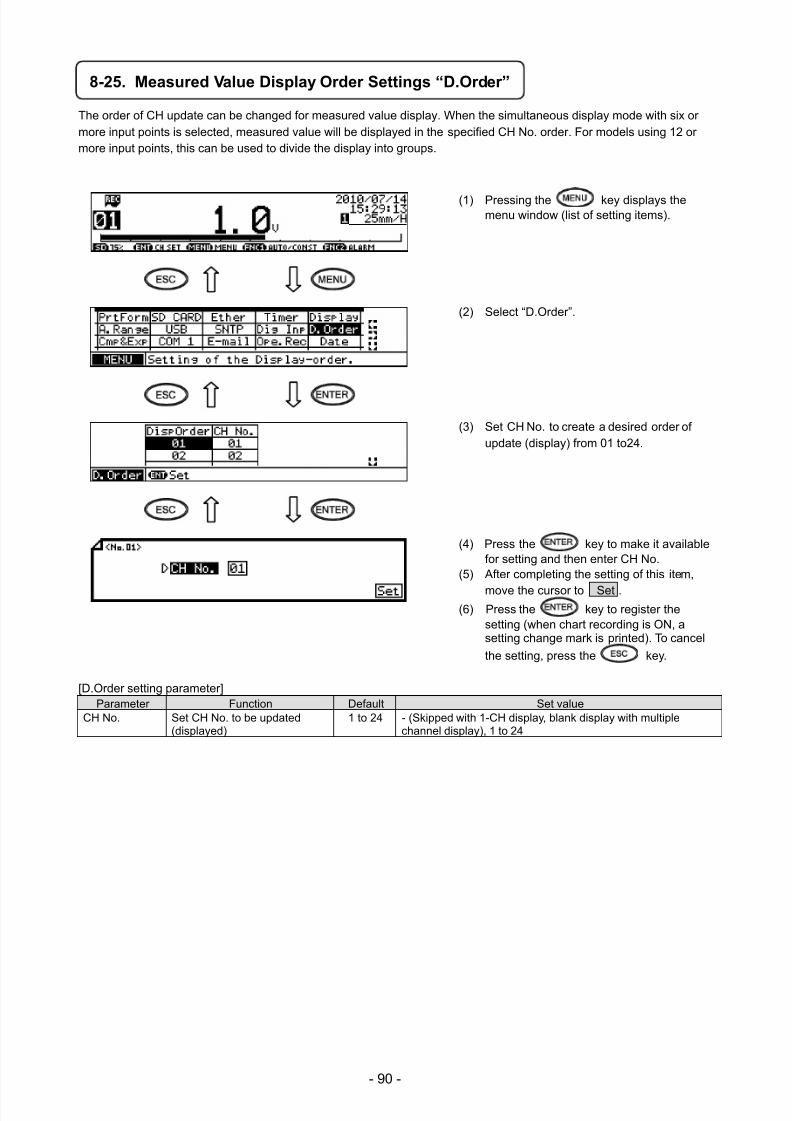
7/23/2019 AH4000 Multi General INE-851B (1)
http://slidepdf.com/reader/full/ah4000-multi-general-ine-851b-1 93/121
- 90 -
8-25. Measured Value Display Order Settings “D.Order”
The order of CH update can be changed for measured value display. When the simultaneous display mode with six ormore input points is selected, measured value will be displayed in the specified CH No. order. For models using 12 ormore input points, this can be used to divide the display into groups.
(1) Pressing the key displays themenu window (list of setting items).
(2) Select “D.Order”.
(3) Set CH No. to create a desired order ofupdate (display) from 01 to24.
(4) Press the key to make it availablefor setting and then enter CH No.
(5) After completing the setting of this item,
move the cursor to Set .(6) Press the key to register the
setting (when chart recording is ON, asetting change mark is printed). To cancel
the setting, press the key.
[D.Order setting parameter]Parameter Function Default Set value
CH No. Set CH No. to be updated(displayed)
1 to 24 - (Skipped with 1-CH display, blank display with multiplechannel display), 1 to 24
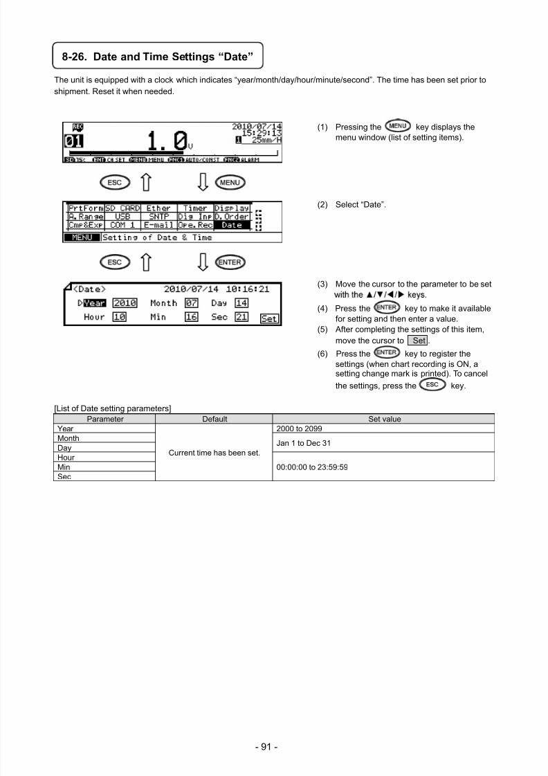
7/23/2019 AH4000 Multi General INE-851B (1)
http://slidepdf.com/reader/full/ah4000-multi-general-ine-851b-1 94/121
- 91 -
8-26. Date and Time Settings “Date”
The unit is equipped with a clock which indicates “year/month/day/hour/minute/second”. The time has been set prior toshipment. Reset it when needed.
(1) Pressing the key displays the
menu window (list of setting items).
(2) Select “Date”.
(3) Move the cursor to the parameter to be set
(4) Press the key to make it availablefor setting and then enter a value.
(5) After completing the settings of this item,move the cursor to Set .
(6) Press the key to register thesettings (when chart recording is ON, asetting change mark is printed). To cancel
the settings, press the key.
[List of Date setting parameters]Parameter Default Set value
Year
Current time has been set.
2000 to 2099Month
Jan 1 to Dec 31DayHour
00:00:00 to 23:59:59MinSec
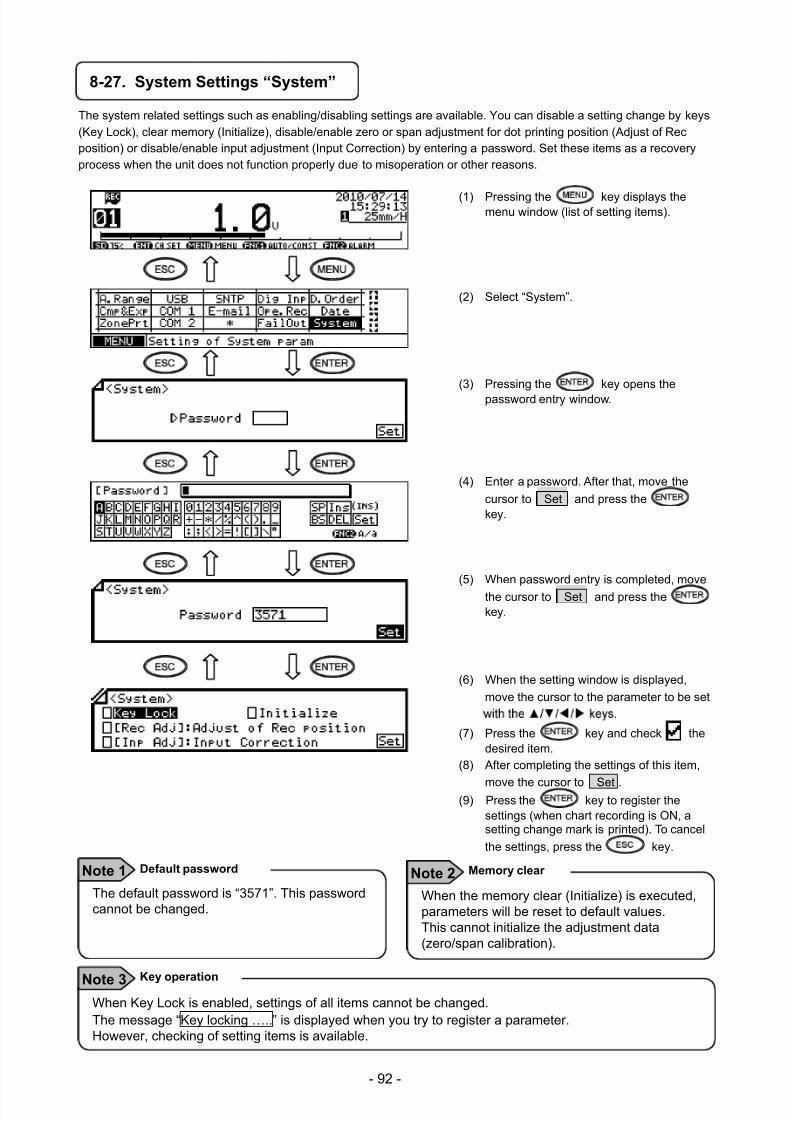
7/23/2019 AH4000 Multi General INE-851B (1)
http://slidepdf.com/reader/full/ah4000-multi-general-ine-851b-1 95/121
- 92 -
8-27. System Settings “System”
The system related settings such as enabling/disabling settings are available. You can disable a setting change by keys(Key Lock), clear memory (Initialize), disable/enable zero or span adjustment for dot printing position (Adjust of Recposition) or disable/enable input adjustment (Input Correction) by entering a password. Set these items as a recoveryprocess when the unit does not function properly due to misoperation or other reasons.
(1) Pressing the key displays themenu window (list of setting items).
(2) Select “System”.
(3) Pressing the key opens thepassword entry window.
(4) Enter a password. After that, move the
cursor to Set and press thekey.
(5) When password entry is completed, move
the cursor to Set and press thekey.
(6) When the setting window is displayed,
move the cursor to the parameter to be set
(7) Press the key and check thedesired item.
(8) After completing the settings of this item,
move the cursor to Set .(9) Press the key to register the
settings (when chart recording is ON, asetting change mark is printed). To cancel
the settings, press the key.
The default password is “3571”. This passwordcannot be changed.
Default password Note 1
When the memory clear (Initialize) is executed,parameters will be reset to default values.This cannot initialize the adjustment data(zero/span calibration).
Memory clear Note 2
When Key Lock is enabled, settings of all items cannot be changed.The message “Key locking …..” is displayed when you try to register a parameter.However, checking of setting items is available.
Key operation Note 3
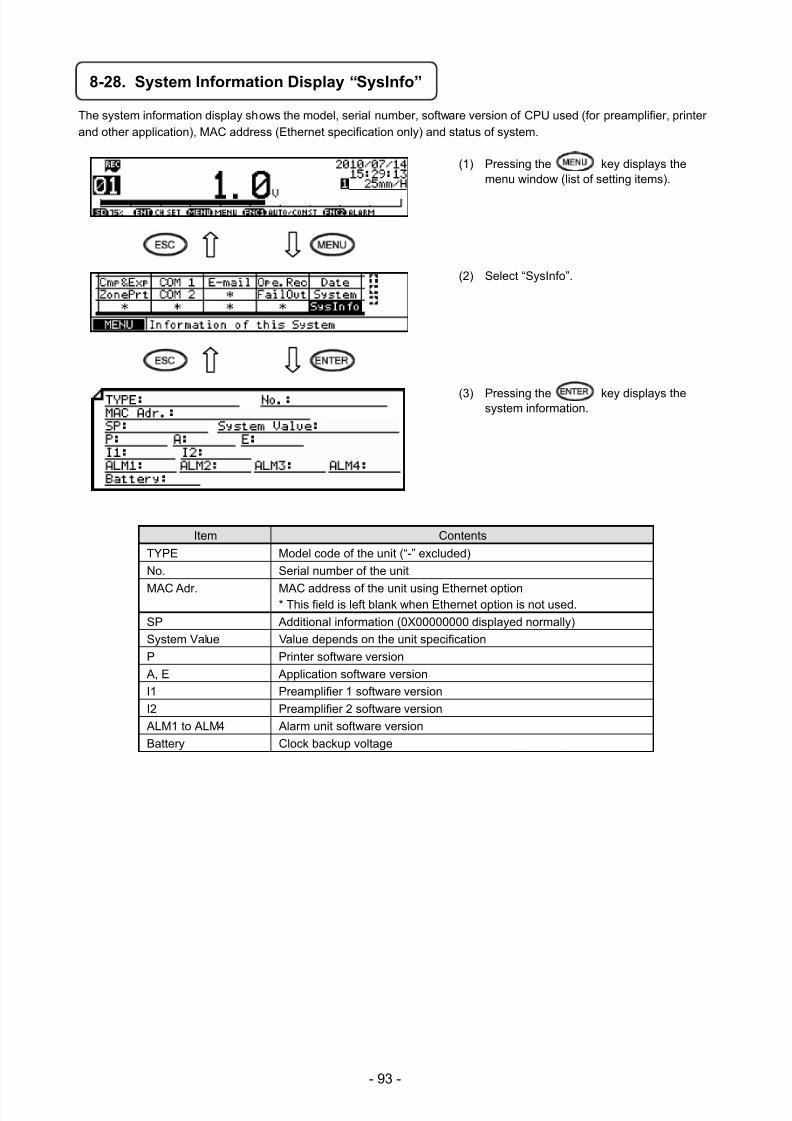
7/23/2019 AH4000 Multi General INE-851B (1)
http://slidepdf.com/reader/full/ah4000-multi-general-ine-851b-1 96/121
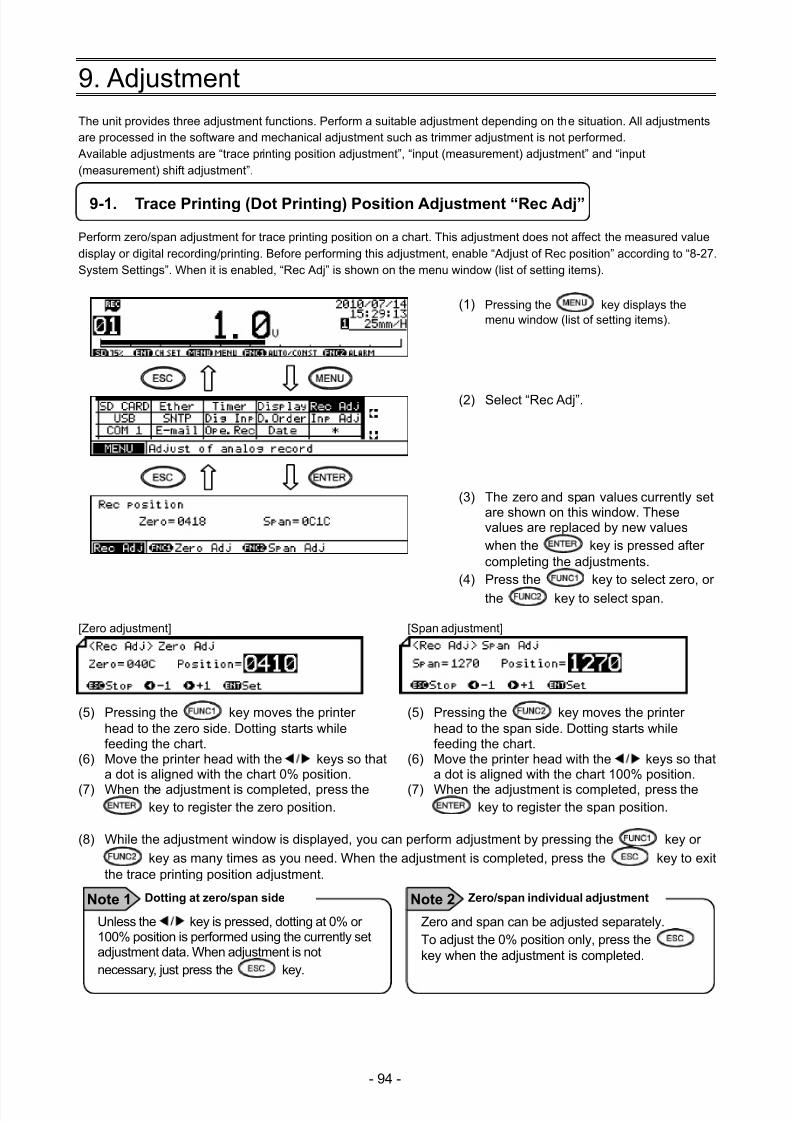
7/23/2019 AH4000 Multi General INE-851B (1)
http://slidepdf.com/reader/full/ah4000-multi-general-ine-851b-1 97/121
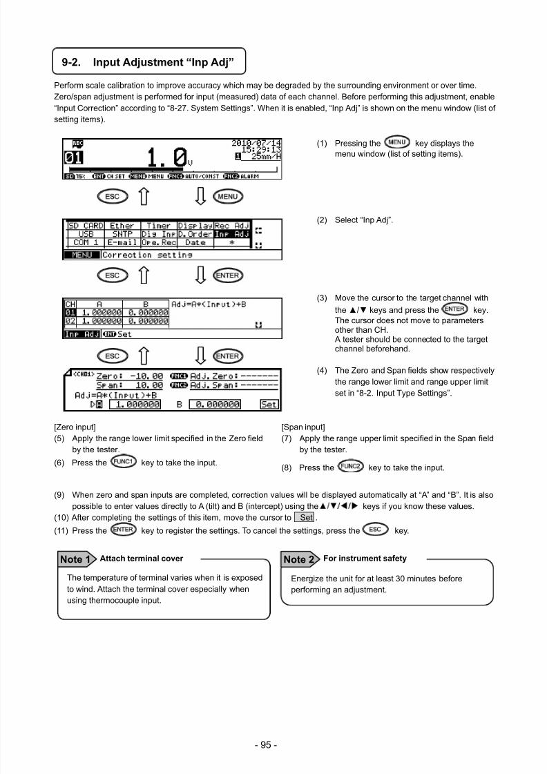
7/23/2019 AH4000 Multi General INE-851B (1)
http://slidepdf.com/reader/full/ah4000-multi-general-ine-851b-1 98/121
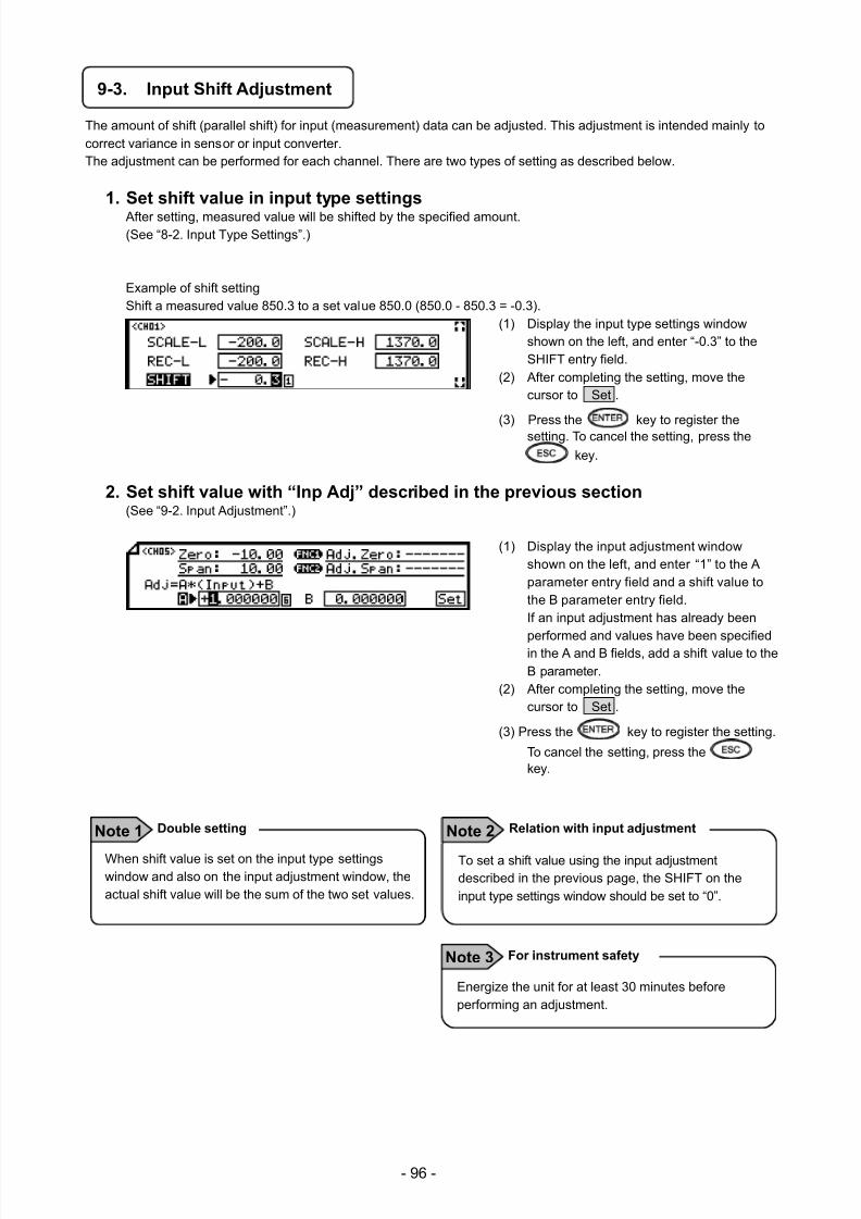
7/23/2019 AH4000 Multi General INE-851B (1)
http://slidepdf.com/reader/full/ah4000-multi-general-ine-851b-1 99/121
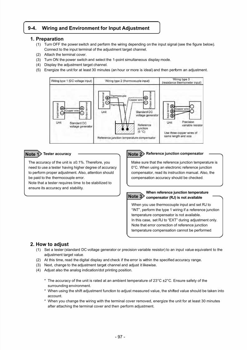
7/23/2019 AH4000 Multi General INE-851B (1)
http://slidepdf.com/reader/full/ah4000-multi-general-ine-851b-1 100/121
- 97 -
9-4. Wiring and Environment for Input Adjustment
1. Preparation (1) Turn OFF the power switch and perform the wiring depending on the input signal (see the figure below).
Connect to the input terminal of the adjustment target channel.(2) Attach the terminal cover.
(3) Turn ON the power switch and select the 1-point simultaneous display mode.(4) Display the adjustment target channel.(5) Energize the unit for at least 30 minutes (an hour or more is ideal) and then perform an adjustment.
2. How to adjust (1) Set a tester (standard DC voltage generator or precision variable resistor) to an input value equivalent to the
adjustment target value.(2) At this time, read the digital display and check if the error is within the specified accuracy range.(3) Next, change to the adjustment target channel and adjust it likewise.(4) Adjust also the analog indication/dot printing position.
* The accuracy of the unit is rated at an ambient temperature of 23°C ±2°C. Ensure safety of thesurrounding environment.
* When using the shift adjustment function to adjust measured value, the shifted value should be taken intoaccount.
* When you change the wiring with the terminal cover removed, energize the unit for at least 30 minutes
after attaching the terminal cover and then perform adjustment.
The accuracy of the unit is ±0.1%. Therefore, youneed to use a tester having higher degree of accuracyto perform proper adjustment. Also, attention shouldbe paid to the thermocouple error.
Note that a tester requires time to be stabilized toensure its accuracy and stability.
Tester accuracy Note 1
Make sure that the reference junction temperature is0°C. When using an electronic reference junctioncompensator, read its instruction manual. Also, thecompensation accuracy should be checked.
Reference junction compensator Note 2
When you use thermocouple input and set RJ to“INT”, perform the type 1 wiring if a reference junctiontemperature compensator is not available.In this case, set RJ to “EXT” during adjustment only.Note that error correction of reference junctiontemperature compensation cannot be performed.
When reference junction temperature
compensator (RJ) is not available Note 3
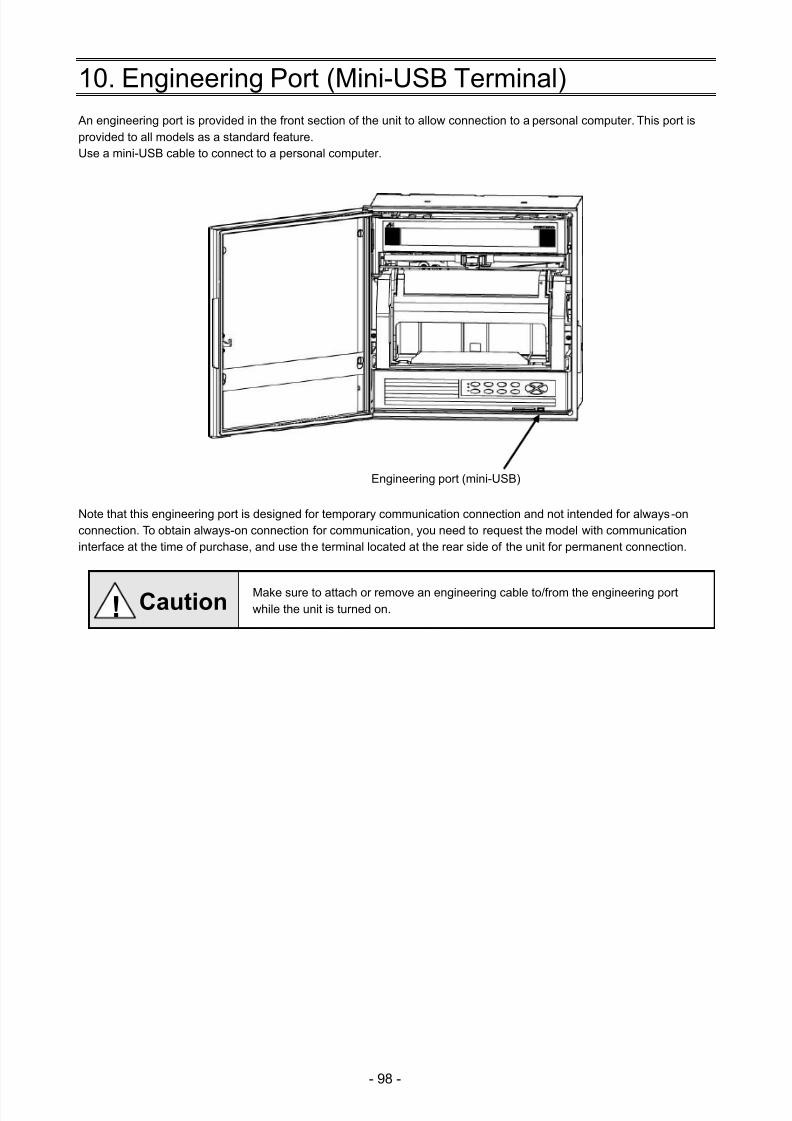
7/23/2019 AH4000 Multi General INE-851B (1)
http://slidepdf.com/reader/full/ah4000-multi-general-ine-851b-1 101/121
- 98 -
10. Engineering Port (Mini-USB Terminal) An engineering port is provided in the front section of the unit to allow connection to a personal computer. This port isprovided to all models as a standard feature.Use a mini-USB cable to connect to a personal computer.
Note that this engineering port is designed for temporary communication connection and not intended for always-onconnection. To obtain always-on connection for communication, you need to request the model with communicationinterface at the time of purchase, and use the terminal located at the rear side of the unit for permanent connection.
Make sure to attach or remove an engineering cable to/from the engineering portwhile the unit is turned on.
Engineering port (mini-USB)
! Caution
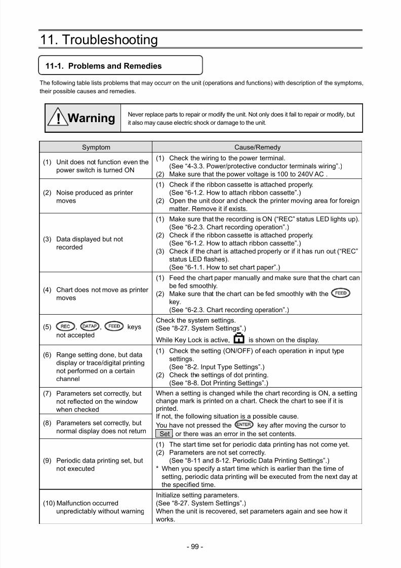
7/23/2019 AH4000 Multi General INE-851B (1)
http://slidepdf.com/reader/full/ah4000-multi-general-ine-851b-1 102/121
- 99 -
11. Troubleshooting
11-1. Problems and Remedies
The following table lists problems that may occurr on the unit (operations and functions) with description of the symptoms,their possible causes and remedies.
Never replace parts to repair or modify the unit. Not only does it fail to repair or modify, butit also may cause electric shock or damage to the unit.
Symptom Cause/Remedy
(1) Unit does not function even thepower switch is turned ON
(1) Check the wiring to the power terminal.(See “4-3.3. Power/protective conductor terminals wiring”.)
(2) Make sure that the power voltage is 100 to 240V AC .
(2) Noise produced as printer
moves
(1) Check if the ribbon cassette is attached properly.(See “6-1.2. How to attach ribbon cassette”.)
(2) Open the unit door and check the printer moving area for foreignmatter. Remove it if exists.
(3) Data displayed but notrecorded
(1) Make sure that the recording is ON (“REC” status LED lights up).(See “6-2.3. Chart recording operation”.)
(2) Check if the ribbon cassette is attached properly.(See “6-1.2. How to attach ribbon cassette”.)
(3) Check if the chart is attached properly or if it has run out (“REC”status LED flashes).(See “6-1.1. How to set chart paper”.)
(4) Chart does not move as printer
moves
(1) Feed the chart paper manually and make sure that the chart canbe fed smoothly.
(2) Make sure that the chart can be fed smoothly with thekey.(See “6-2.3. Chart recording operation”.)
(5) , , keysnot accepted
Check the system settings.(See “8-27. System Settings”.)
While Key Lock is active, is shown on the display.
(6) Range setting done, but datadisplay or trace/digital printingnot performed on a certainchannel
(1) Check the setting (ON/OFF) of each operation in input typesettings.(See “8-2. Input Type Settings”.)
(2) Check the settings of dot printing.(See “8-8. Dot Printing Settings”.)
(7) Parameters set correctly, butnot reflected on the windowwhen checked
When a setting is changed while the chart recording is ON, a settingchange mark is printed on a chart. Check the chart to see if it isprinted.If not, the following situation is a possible cause.You have not pressed the key after moving the cursor to
Set , or there was an error in the set contents.
(8) Parameters set correctly, butnormal display does not return
(9) Periodic data printing set, butnot executed
(1) The start time set for periodic data printing has not come yet.(2) Parameters are not set correctly.
(See “8-11 and 8-12. Periodic Data Printing Settings”.)* When you specify a start time which is earlier than the time of
setting, periodic data printing will be executed from the next day atthe specified time.
(10) Malfunction occurredunpredictably without warning
Initialize setting parameters.(See “8-27. System Settings”.)When the unit is recovered, set parameters again and see how itworks.
! Warning
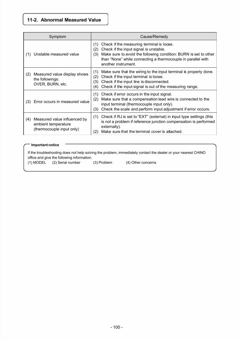
7/23/2019 AH4000 Multi General INE-851B (1)
http://slidepdf.com/reader/full/ah4000-multi-general-ine-851b-1 103/121
- 100 -
11-2. Abnormal Measured Value
Symptom Cause/Remedy
(1) Unstable measured value
(1) Check if the measuring terminal is loose.(2) Check if the input signal is unstable.(3) Make sure to avoid the following condition: BURN is set to other
than “None” while connecting a thermocouple in parallel withanother instrument.
(2) Measured value display showsthe followings:OVER, BURN, etc.
(1) Make sure that the wiring to the input terminal is properly done.(2) Check if the input terminal is loose.(3) Check if the input line is disconnected.(4) Check if the input signal is out of the measuring range.
(3) Error occurs in measured value
(1) Check if error occurs in the input signal.
(2) Make sure that a compensation lead wire is connected to theinput terminal (thermocouple input only).
(3) Check the scale and perform input adjustment if error occurs.
(4) Measured value influenced byambient temperature(thermocouple input only)
(1) Check if RJ is set to “EXT” (external) in input type settings (thisis not a problem if reference junction compensation is performedexternally).
(2) Make sure that the terminal cover is attached.
If the troubleshooting does not help solving the problem, immediately contact the dealer or your nearest CHINOoffice and give the following information.(1) MODEL (2) Serial number (3) Problem (4) Other concerns
Important notice
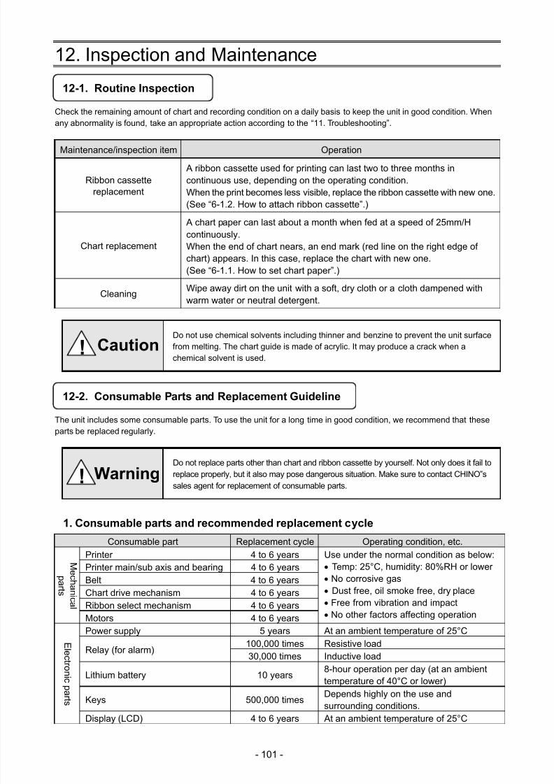
7/23/2019 AH4000 Multi General INE-851B (1)
http://slidepdf.com/reader/full/ah4000-multi-general-ine-851b-1 104/121
- 101 -
12. Inspection and Maintenance
12-1. Routine Inspection
Check the remaining amount of chart and recording condition on a daily basis to keep the unit in good condition. Whenany abnormality is found, take an appropriate action according to the “11. Troubleshooting”.
Maintenance/inspection item Operation
Ribbon cassettereplacement
A ribbon cassette used for printing can last two to three months incontinuous use, depending on the operating condition.When the print becomes less visible, replace the ribbon cassette with new one.(See “6-1.2. How to attach ribbon cassette”.)
Chart replacement
A chart paper can last about a month when fed at a speed of 25mm/Hcontinuously.When the end of chart nears, an end mark (red line on the right edge ofchart) appears. In this case, replace the chart with new one.
(See “6-1.1. How to set chart paper”.)
Cleaning
Wipe away dirt on the unit with a soft, dry cloth or a cloth dampened withwarm water or neutral detergent.
Do not use chemical solvents including thinner and benzine to prevent the unit surfacefrom melting. The chart guide is made of acrylic. It may produce a crack when achemical solvent is used.
12-2. Consumable Parts and Replacement Guideline
The unit includes some consumable parts. To use the unit for a long time in good condition, we recommend that theseparts be replaced regularly.
Do not replace parts other than chart and ribbon cassette by yourself. Not only does it fail toreplace properly, but it also may pose dangerous situation. Make sure to contact CHINO‟ssales agent for replacement of consumable parts.
1. Consumable parts and recommended replacement cycle
Consumable part Replacement cycle Operating condition, etc.
M e c h ani c al
p ar t s
Printer 4 to 6 years Use under the normal condition as below: Temp: 25°C, humidity: 80%RH or lower No corrosive gas Dust free, oil smoke free, dry place Free from vibration and impact No other factors affecting operation
Printer main/sub axis and bearing 4 to 6 yearsBelt 4 to 6 yearsChart drive mechanism 4 to 6 yearsRibbon select mechanism 4 to 6 yearsMotors 4 to 6 years
E l e c t r oni c p ar t s
Power supply 5 years At an ambient temperature of 25°C
Relay (for alarm)100,000 times Resistive load30,000 times Inductive load
Lithium battery 10 years8-hour operation per day (at an ambienttemperature of 40°C or lower)
Keys 500,000 timesDepends highly on the use andsurrounding conditions.
Display (LCD) 4 to 6 years At an ambient temperature of 25°C
! Caution
! Warning
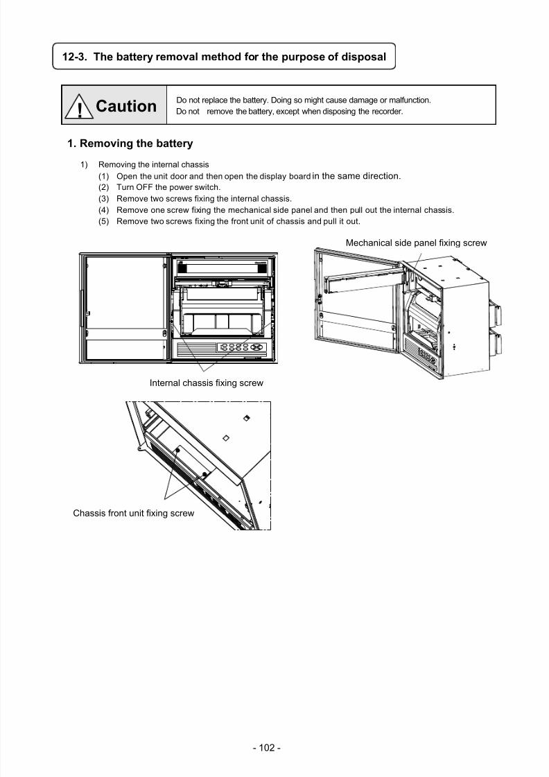
7/23/2019 AH4000 Multi General INE-851B (1)
http://slidepdf.com/reader/full/ah4000-multi-general-ine-851b-1 105/121
- 102 -
12-3. The battery removal method for the purpose of disposal
Do not replace the battery. Doing so might cause damage or malfunction.Do not remove the battery, except when disposing the recorder.
1. Removing the battery
1) Removing the internal chassis
(1) Open the unit door and then open the display board in the same direction. (2) Turn OFF the power switch.(3) Remove two screws fixing the internal chassis.(4) Remove one screw fixing the mechanical side panel and then pull out the internal chassis.(5) Remove two screws fixing the front unit of chassis and pull it out.
! Caution
Mechanical side panel fixing screw
Chassis front unit fixing screw
Internal chassis fixing screw
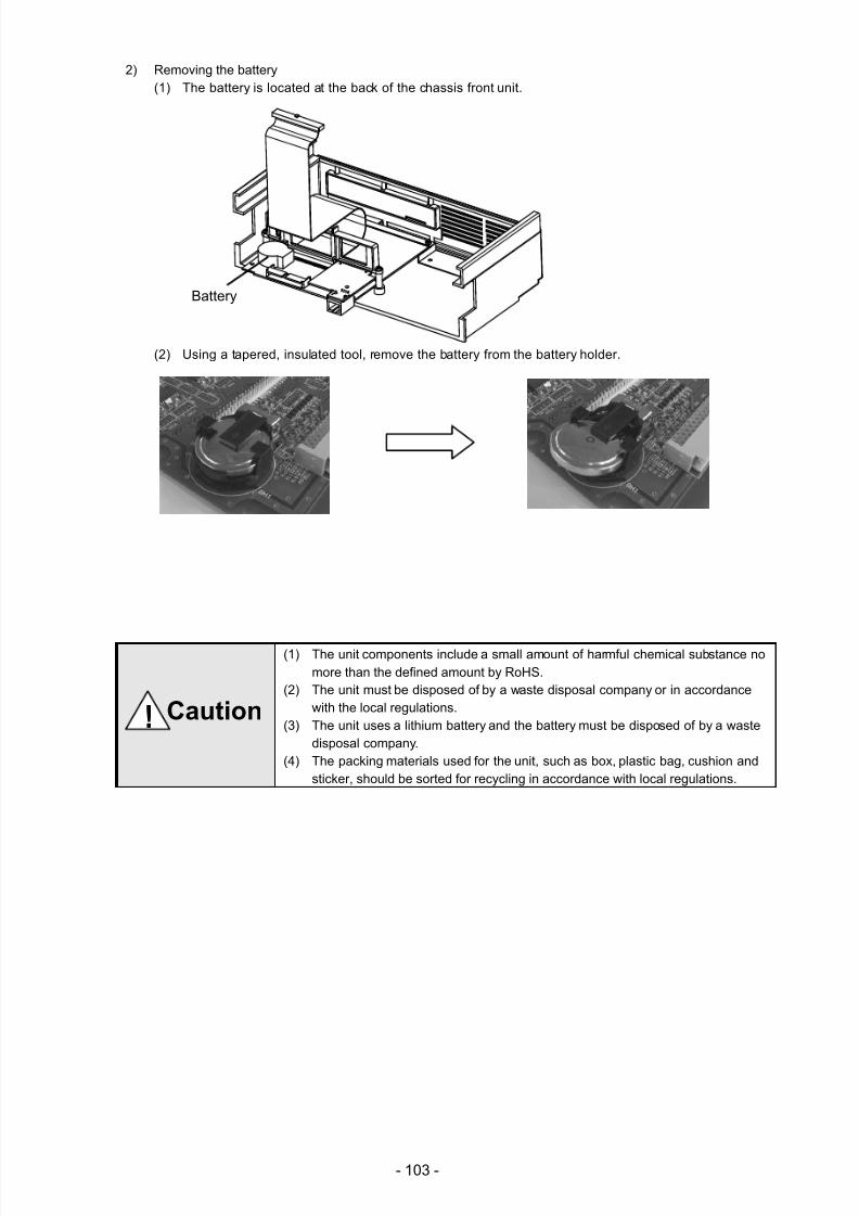
7/23/2019 AH4000 Multi General INE-851B (1)
http://slidepdf.com/reader/full/ah4000-multi-general-ine-851b-1 106/121
- 103 -
2) Removing the battery
(1) The battery is located at the back of the chassis front unit.
(2) Using a tapered, insulated tool, remove the battery from the battery holder.
(1) The unit components include a small amount of harmful chemical substance nomore than the defined amount by RoHS.
(2) The unit must be disposed of by a waste disposal company or in accordancewith the local regulations.
(3) The unit uses a lithium battery and the battery must be disposed of by a wastedisposal company.
(4) The packing materials used for the unit, such as box, plastic bag, cushion andsticker, should be sorted for recycling in accordance with local regulations.
Battery
! Caution
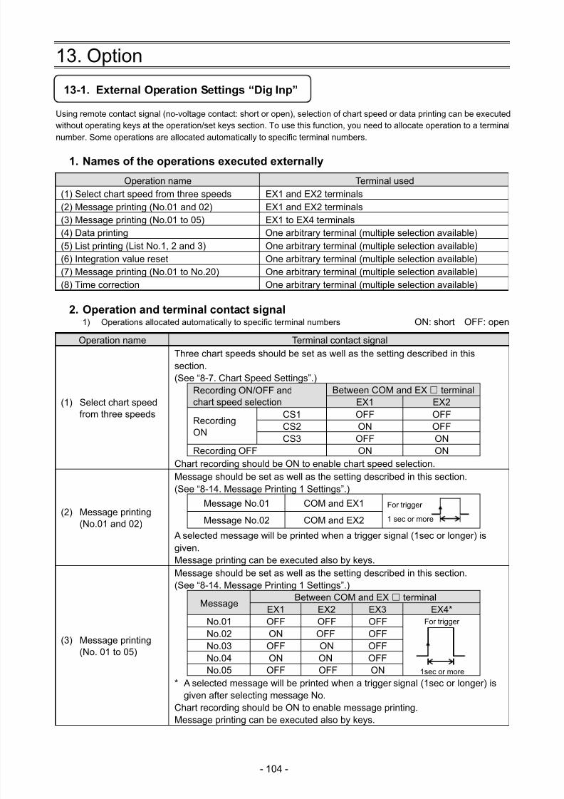
7/23/2019 AH4000 Multi General INE-851B (1)
http://slidepdf.com/reader/full/ah4000-multi-general-ine-851b-1 107/121
- 104 -
13. Option
13-1. External Operation Settings “Dig Inp”
Using remote contact signal (no-voltage contact: short or open), selection of chart speed or data printing can be executedwithout operating keys at the operation/set keys section. To use this function, you need to allocate operation to a terminal
number. Some operations are allocated automatically to specific terminal numbers.
1. Names of the operations executed externally
Operation name Terminal used(1) Select chart speed from three speeds EX1 and EX2 terminals(2) Message printing (No.01 and 02) EX1 and EX2 terminals(3) Message printing (No.01 to 05) EX1 to EX4 terminals(4) Data printing One arbitrary terminal (multiple selection available)
(5) List printing (List No.1, 2 and 3) One arbitrary terminal (multiple selection available) (6) Integration value reset One arbitrary terminal (multiple selection available) (7) Message printing (No.01 to No.20) One arbitrary terminal (multiple selection available)
(8) Time correction One arbitrary terminal (multiple selection available)
2. Operation and terminal contact signal 1) Operations allocated automatically to specific terminal numbers
ON: short OFF: open
Operation name Terminal contact signal
(1) Select chart speedfrom three speeds
Three chart speeds should be set as well as the setting described in thissection.(See “8-7. Chart Speed Settings”.)
Recording ON/OFF andchart speed selection
Between COM and EX terminal EX1 EX2
RecordingON
CS1 OFF OFFCS2 ON OFFCS3 OFF ON
Recording OFF ON ONChart recording should be ON to enable chart speed selection.
(2) Message printing(No.01 and 02)
Message should be set as well as the setting described in this section.(See “8-14. Message Printing 1 Settings”.)
Message No.01 COM and EX1
Message No.02
COM and EX2
A selected message will be printed when a trigger signal (1sec or longer) isgiven.
Message printing can be executed also by keys.
(3) Message printing(No. 01 to 05)
Message should be set as well as the setting described in this section.(See “8-14. Message Printing 1 Settings”.)
Message Between COM and EX terminal
EX1 EX2 EX3 EX4* No.01 OFF OFF OFF For trigger
No.02
ON OFF OFFNo.03 OFF ON OFFNo.04 ON ON OFFNo.05 OFF OFF ON
* A selected message will be printed when a trigger signal (1sec or longer) is
given after selecting message No.Chart recording should be ON to enable message printing.Message printing can be executed also by keys.
1 sec or more
For trigger
1sec or more
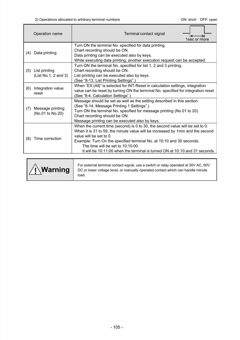
7/23/2019 AH4000 Multi General INE-851B (1)
http://slidepdf.com/reader/full/ah4000-multi-general-ine-851b-1 108/121
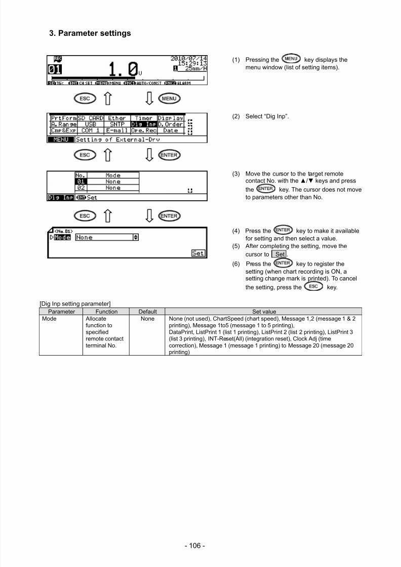
7/23/2019 AH4000 Multi General INE-851B (1)
http://slidepdf.com/reader/full/ah4000-multi-general-ine-851b-1 109/121
- 106 -
3. Parameter settings
(1) Pressing the key displays themenu window (list of setting items).
(2) Select “Dig Inp”.
(3) Move the cursor to the target remotecontact No. with the / keys and press
the key. The cursor does not move
to parameters other than No.
(4) Press the key to make it availablefor setting and then select a value.
(5) After completing the setting, move thecursor to Set .
(6) Press the key to register thesetting (when chart recording is ON, asetting change mark is printed). To cancel
the setting, press the key.
[Dig Inp setting parameter]Parameter Function Default Set value
Mode Allocatefunction tospecifiedremote contactterminal No.
None None (not used), ChartSpeed (chart speed), Message 1,2 (message 1 & 2printing), Message 1to5 (message 1 to 5 printing),DataPrint, ListPrint 1 (list 1 printing), ListPrint 2 (list 2 printing), ListPrint 3(list 3 printing), INT-Reset(All) (integration reset), Clock Adj (timecorrection), Message 1 (message 1 printing) to Message 20 (message 20printing)
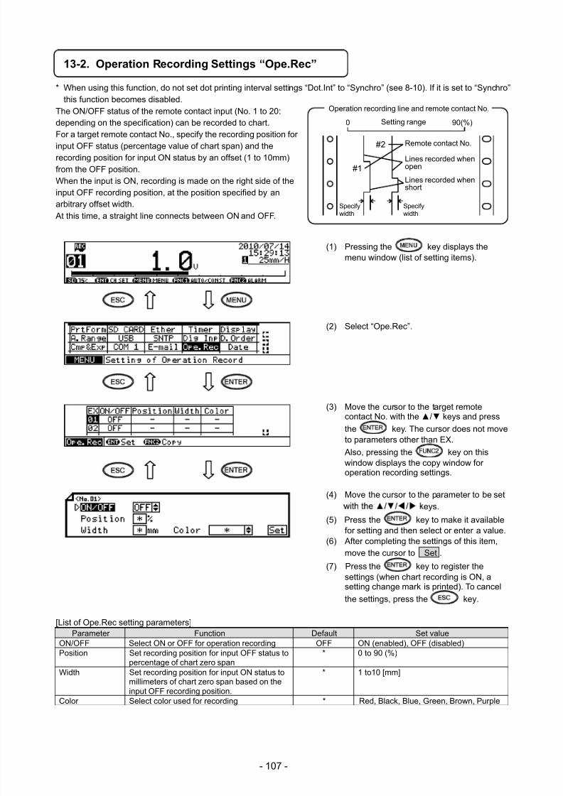
7/23/2019 AH4000 Multi General INE-851B (1)
http://slidepdf.com/reader/full/ah4000-multi-general-ine-851b-1 110/121
- 107 -
13-2. Operation Recording Settings “Ope.Rec”
* When using this function, do not set dot printing interval settings “Dot.Int” to “Synchro” (see 8-10). If it is set to “Synchro”this function becomes disabled.
The ON/OFF status of the remote contact input (No. 1 to 20:depending on the specification) can be recorded to chart.For a target remote contact No., specify the recording position forinput OFF status (percentage value of chart span) and therecording position for input ON status by an offset (1 to 10mm)from the OFF position.When the input is ON, recording is made on the right side of theinput OFF recording position, at the position specified by anarbitrary offset width. At this time, a straight line connects between ON and OFF.
(1) Pressing the key displays themenu window (list of setting items).
(2) Select “Ope.Rec”.
(3) Move the cursor to the target remote
contact No. with the / keys and pressthe key. The cursor does not moveto parameters other than EX.
Also, pressing the key on thiswindow displays the copy window foroperation recording settings.
(4) Move the cursor to the parameter to be seteys.
(5) Press the key to make it availablefor setting and then select or enter a value.
(6) After completing the settings of this item,move the cursor to Set .
(7) Press the key to register thesettings (when chart recording is ON, asetting change mark is printed). To cancel
the settings, press the key.
[List of Ope.Rec setting parameters] Parameter Function Default Set value
ON/OFF Select ON or OFF for operation recording OFF ON (enabled), OFF (disabled)Position Set recording position for input OFF status to
percentage of chart zero span* 0 to 90 (%)
Width Set recording position for input ON status tomillimeters of chart zero span based on theinput OFF recording position.
* 1 to10 [mm]
Color Select color used for recording * Red, Black, Blue, Green, Brown, Purple
Operation recording line and remote contact No.
Setting range
#1
#2 Remote contact No.
Lines recorded whenopen
Lines recorded whenshort
Specifywidth
0 90(%)
Specifywidth
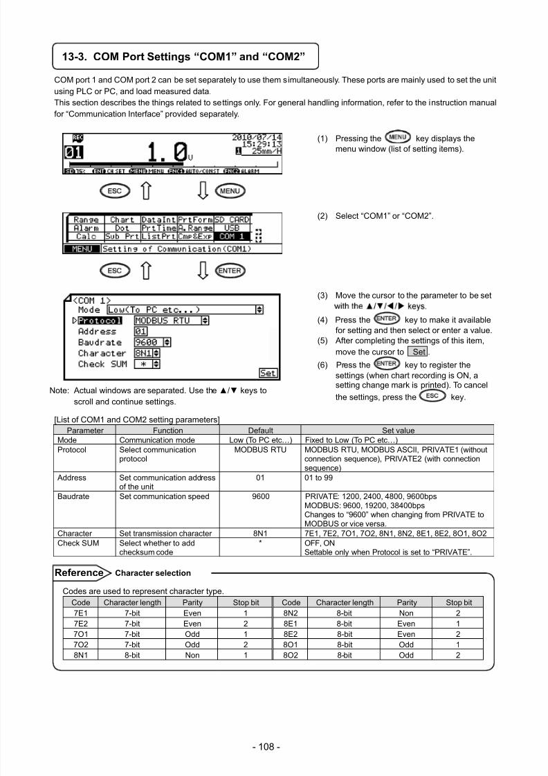
7/23/2019 AH4000 Multi General INE-851B (1)
http://slidepdf.com/reader/full/ah4000-multi-general-ine-851b-1 111/121
- 108 -
13-3. COM Port Settings “COM1” and “COM2”
COM port 1 and COM port 2 can be set separately to use them simultaneously. These ports are mainly used to set the unitusing PLC or PC, and load measured data. This section describes the things related to settings only. For general handling information, refer to the instruction manualfor “Communication Interface” provided separately.
(1) Pressing the key displays themenu window (list of setting items).
(2) Select “COM1” or “COM2”.
(3) Move the cursor to the parameter to be set
(4) Press the key to make it availablefor setting and then select or enter a value.
(5) After completing the settings of this item,move the cursor to Set .
(6) Press the key to register thesettings (when chart recording is ON, asetting change mark is printed). To cancel
the settings, press the key.
[List of COM1 and COM2 setting parameters]Parameter Function Default Set value
Mode Communication mode Low (To PC etc…) Fixed to Low (To PC etc…)Protocol Select communication
protocolMODBUS RTU MODBUS RTU, MODBUS ASCII, PRIVATE1 (without
connection sequence), PRIVATE2 (with connectionsequence)
Address Set communication addressof the unit
01 01 to 99
Baudrate Set communication speed 9600 PRIVATE: 1200, 2400, 4800, 9600bpsMODBUS: 9600, 19200, 38400bpsChanges to “9600” when changing from PRIVATE toMODBUS or vice versa.
Character Set transmission character 8N1 7E1, 7E2, 7O1, 7O2, 8N1, 8N2, 8E1, 8E2, 8O1, 8O2
Check SUM Select whether to addchecksum code * OFF, ONSettable only when Protocol is set to “PRIVATE”.
Note: Actual windows are separated. Use the / keys toscroll and continue settings.
Codes are used to represent character type.Code Character length Parity Stop bit Code Character length Parity Stop bit7E1 7-bit Even 1 8N2 8-bit Non 27E2 7-bit Even 2 8E1 8-bit Even 17O1 7-bit Odd 1 8E2 8-bit Even 27O2 7-bit Odd 2 8O1 8-bit Odd 18N1 8-bit Non 1 8O2 8-bit Odd 2
Character selection Reference
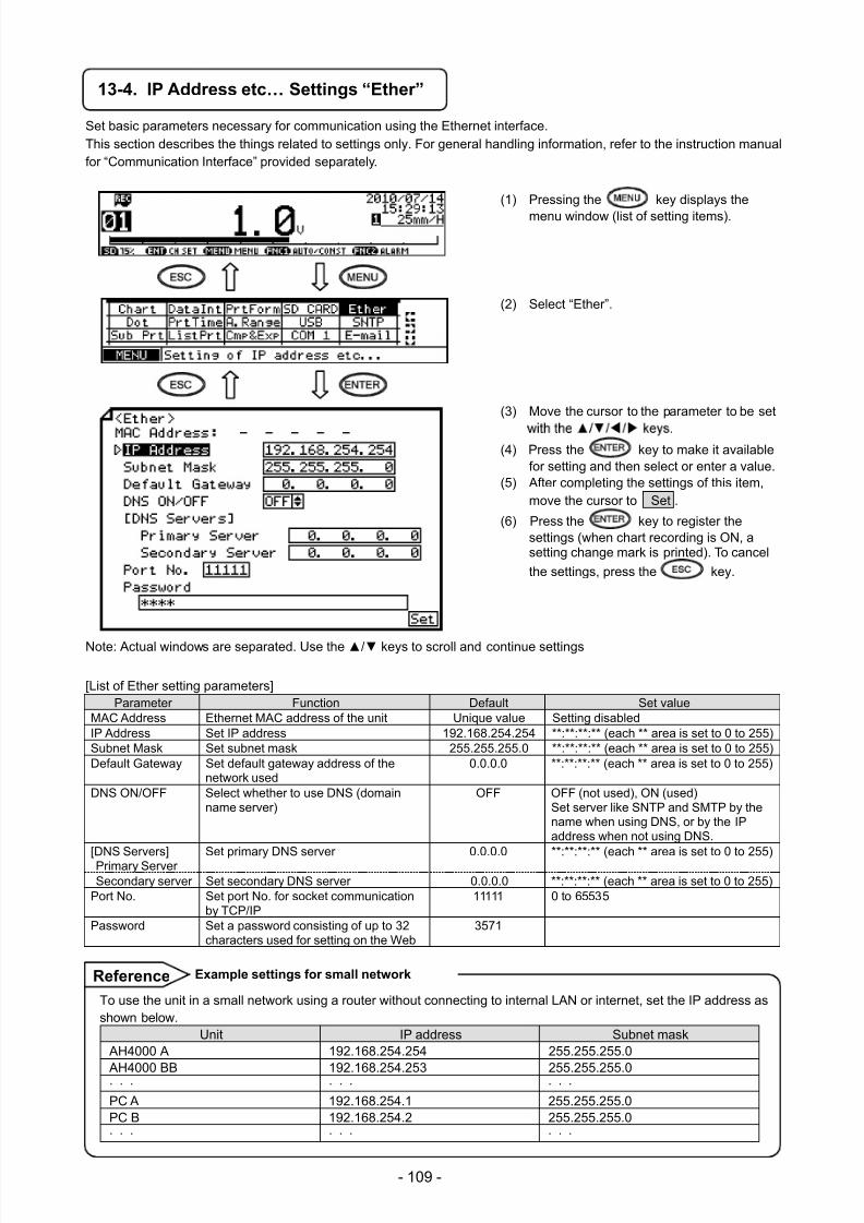
7/23/2019 AH4000 Multi General INE-851B (1)
http://slidepdf.com/reader/full/ah4000-multi-general-ine-851b-1 112/121
- 109 -
13-4. IP Address etc… Settings “Ether”
Set basic parameters necessary for communication using the Ethernet interface.This section describes the things related to settings only. For general handling information, refer to the instruction manualfor “Communication Interface” provided separately.
(1) Pressing the key displays the
menu window (list of setting items).
(2) Select “Ether”.
(3) Move the cursor to the parameter to be set
(4) Press the key to make it availablefor setting and then select or enter a value.
(5) After completing the settings of this item,move the cursor to Set .
(6) Press the key to register thesettings (when chart recording is ON, asetting change mark is printed). To cancel
the settings, press the key.
Note: Actual windows are separated. Use the / keys to scroll and continue settings
[List of Ether setting parameters]Parameter Function Default Set value
MAC Address Ethernet MAC address of the unit Unique value Setting disabledIP Address Set IP address 192.168.254.254 **:**:**:** (each ** area is set to 0 to 255)Subnet Mask Set subnet mask 255.255.255.0 **:**:**:** (each ** area is set to 0 to 255)Default Gateway Set default gateway address of the
network used0.0.0.0 **:**:**:** (each ** area is set to 0 to 255)
DNS ON/OFF Select whether to use DNS (domainname server)
OFF OFF (not used), ON (used)Set server like SNTP and SMTP by thename when using DNS, or by the IPaddress when not using DNS.
[DNS Servers]Primary Server Set primary DNS server 0.0.0.0 **:**:**:** (each ** area is set to 0 to 255)Secondary server Set secondary DNS server 0.0.0.0 **:**:**:** (each ** area is set to 0 to 255)
Port No. Set port No. for socket communicationby TCP/IP
11111 0 to 65535
Password Set a password consisting of up to 32characters used for setting on the Web
3571
To use the unit in a small network using a router without connecting to internal LAN or internet, set the IP address asshown below.
Unit IP address Subnet mask AH4000 A 192.168.254.254 255.255.255.0
AH4000 BB 192.168.254.253 255.255.255.0∙
∙
∙
∙
∙
∙
∙
∙
∙
PC A 192.168.254.1 255.255.255.0PC B 192.168.254.2 255.255.255.0∙
∙
∙
∙
∙
∙
∙
∙
∙
Example settings for small network Reference
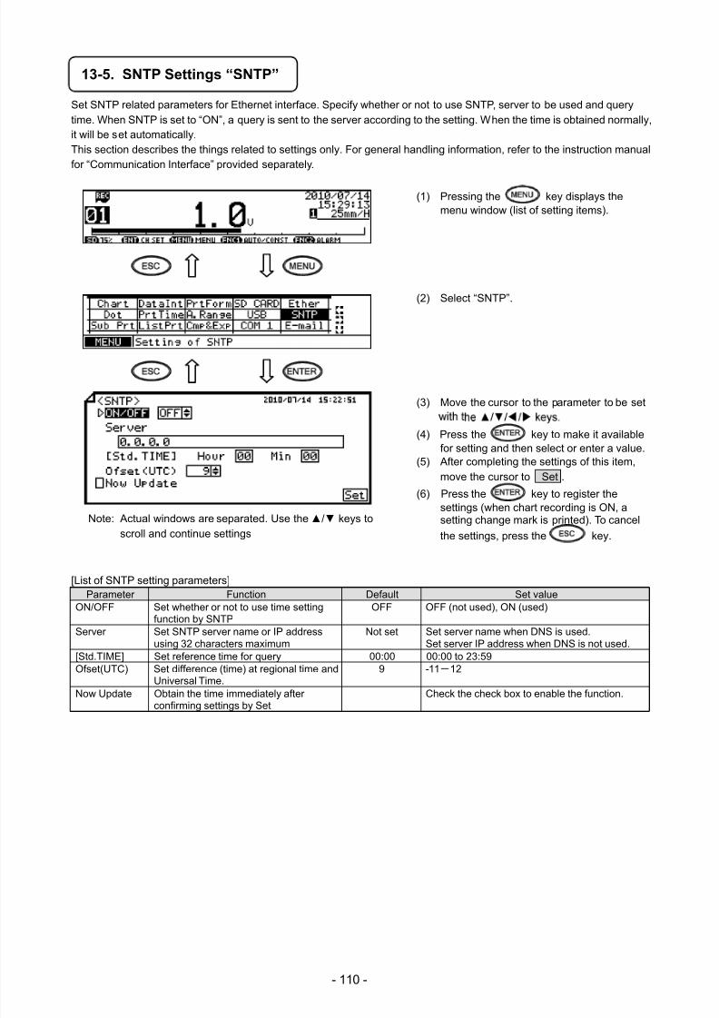
7/23/2019 AH4000 Multi General INE-851B (1)
http://slidepdf.com/reader/full/ah4000-multi-general-ine-851b-1 113/121
- 110 -
13-5. SNTP Settings “SNTP”
Set SNTP related parameters for Ethernet interface. Specify whether or not to use SNTP, server to be used and querytime. When SNTP is set to “ON”, a query is sent to the server according to the setting. When the time is obtained normally,it will be set automatically.This section describes the things related to settings only. For general handling information, refer to the instruction manualfor “Communication Interface” provided separately.
(1) Pressing the key displays themenu window (list of setting items).
(2) Select “SNTP”.
(3) Move the cursor to the parameter to be set
(4) Press the key to make it availablefor setting and then select or enter a value.
(5) After completing the settings of this item,move the cursor to Set .
(6) Press the key to register thesettings (when chart recording is ON, asetting change mark is printed). To cancel
the settings, press the key.
[List of SNTP setting parameters]Parameter Function Default Set value
ON/OFF Set whether or not to use time settingfunction by SNTP
OFF OFF (not used), ON (used)
Server Set SNTP server name or IP addressusing 32 characters maximum
Not set Set server name when DNS is used.Set server IP address when DNS is not used.
[Std.TIME] Set reference time for query 00:00 00:00 to 23:59Ofset(UTC) Set difference (time) at regional time and
Universal Time.9 -11-12
Now Update Obtain the time immediately afterconfirming settings by Set
Check the check box to enable the function.
Note: Actual windows are separated. Use the / keys to
scroll and continue settings
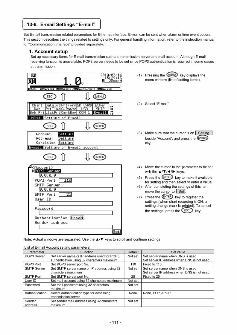
7/23/2019 AH4000 Multi General INE-851B (1)
http://slidepdf.com/reader/full/ah4000-multi-general-ine-851b-1 114/121
- 111 -
13-6. E-mail Settings “E-mail”
Set E-mail transmission related parameters for Ethernet interface. E-mail can be sent when alarm or time event occurs.
This section describes the things related to settings only. For general handling information, refer to the instruction manualfor “Communication Interface” provided separately.
1. Account setupSet up necessary items for E-mail transmission such as transmission server and mail account. Although E-mailreceiving function is unavailable, POP3 server needs to be set since POP3 authentication is required in some casesat transmission.
(1) Pressing the key displays themenu window (list of setting items).
(2) Select “E-mail”.
(3) Make sure that the cursor is on Setting
beside “Account”, and press thekey.
(4) Move the cursor to the parameter to be setwit
(5) Press the key to make it availablefor setting and then select or enter a value.
(6) After completing the settings of this item,move the cursor to Set .
(7) Press the key to register thesettings (when chart recording is ON, asetting change mark is printed). To cancel
the settings, press the key.
Note: Actual windows are separated. Use the / keys to scroll and continue settings
[List of E-mail Account setting parameters]Parameter Function Default Set value
POP3 Server Set server name or IP address used for POP3authentication using 32 characters maximum
Not set Set server name when DNS is used.Set server IP address when DNS is not used.
POP3 Port Set POP3 server port No. 110 Fixed to 110SMTP Server Set SMTP server name or IP address using 32
characters maximumNot set Set server name when DNS is used.
Set server IP address when DNS is not used.SMTP Port Set SMTP server port No. 25 Fixed to 25User ID Set mail account using 32 characters maximum Not setPassword Set mail password using 32 characters
maximumNot set
Authentication Select authentication type for accessingtransmission server None None, POP, APOP
Senderaddress
Set sender mail address using 32 charactersmaximum
Not set
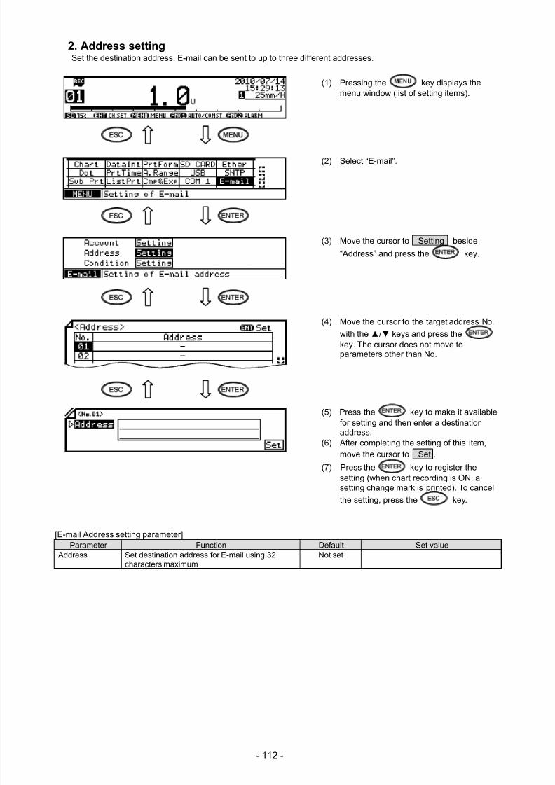
7/23/2019 AH4000 Multi General INE-851B (1)
http://slidepdf.com/reader/full/ah4000-multi-general-ine-851b-1 115/121
- 112 -
2. Address settingSet the destination address. E-mail can be sent to up to three different addresses.
(1) Pressing the key displays themenu window (list of setting items).
(2) Select “E-mail”.
(3) Move the cursor to Setting beside
“Address” and press the key.
(4) Move the cursor to the target address No.
with the / keys and press thekey. The cursor does not move toparameters other than No.
(5) Press the key to make it availablefor setting and then enter a destinationaddress.
(6) After completing the setting of this item,move the cursor to Set .
(7) Press the key to register thesetting (when chart recording is ON, asetting change mark is printed). To cancel
the setting, press the key.
[E-mail Address setting parameter]Parameter Function Default Set value
Address Set destination address for E-mail using 32characters maximum
Not set
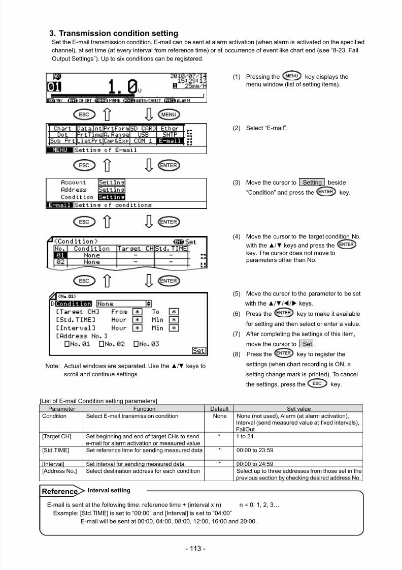
7/23/2019 AH4000 Multi General INE-851B (1)
http://slidepdf.com/reader/full/ah4000-multi-general-ine-851b-1 116/121
- 113 -
3. Transmission condition settingSet the E-mail transmission condition. E-mail can be sent at alarm activation (when alarm is activated on the specifiedchannel), at set time (at every interval from reference time) or at occurrence of event like chart end (see “8-23. FailOutput Settings”). Up to six conditions can be registered.
(1) Pressing the key displays themenu window (list of setting items).
(2) Select “E-mail”.
(3) Move the cursor to Setting beside
“Condition” and press the key.
(4) Move the cursor to the target condition No.
with the / keys and press thekey. The cursor does not move toparameters other than No.
(5) Move the cursor to the parameter to be set
(6) Press the key to make it available
for setting and then select or enter a value.
(7) After completing the settings of this item,
move the cursor to Set .
(8) Press the key to register the
settings (when chart recording is ON, a
setting change mark is printed). To cancel
the settings, press the key.
[List of E-mail Condition setting parameters]Parameter Function Default Set value
Condition Select E-mail transmission condition None None (not used), Alarm (at alarm activation),Interval (send measured value at fixed intervals),FailOut
[Target CH] Set beginning and end of target CHs to sende-mail for alarm activation or measured value
* 1 to 24
[Std.TIME] Set reference time for sending measured data * 00:00 to 23:59
[Interval] Set interval for sending measured data * 00:00 to 24:59[Address No.] Select destination address for each condition Select up to three addresses from those set in the
previous section by checking desired address No.
Note: Actual windows are separated. Use the / keys toscroll and continue settings
E-mail is sent at the following time: reference time + (interval x n) n = 0, 1, 2, 3…Example: [Std.TIME] is set to “00:00” and [Interval] is set to “04:00”
E-mail will be sent at 00:00, 04:00, 08:00, 12:00, 16:00 and 20:00.
Interval setting Reference
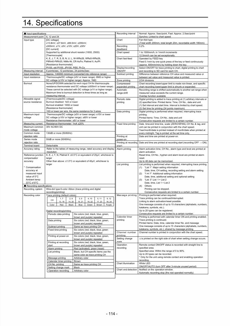
7/23/2019 AH4000 Multi General INE-851B (1)
http://slidepdf.com/reader/full/ah4000-multi-general-ine-851b-1 117/121
- 114 -
14. Specifications Input specificationsMeasurement point 6, 12 and 24Input type [DC voltage]
±13.8mV, ±27.6mV, ±69.0mV, ±200mV,±500mV, ±1V, ±5V, ±10V, ±20V, ±50V[DC current]Supported by additional shunt resistor (100Ω, 250Ω)[Thermocouple]K, E, J, T, R, S, B, N, U, L, W-WRe26, WRe5-WRe26,PtRh40-PtRh20, NiMo-Ni, CR-AuFe, Platinel II, Au/Pt[Resistance thermometer]Pt100, old Pt100, JPt100, Pt50, Pt-Co
Measuring interval 6 points/sec, 12 points/sec, 24 points/2secInput resolution Approx. 1/40000 minimum (converted into reference range)Input resistance Thermocouple/DC voltage (±5V or lower range): 6MΩ or higher
DC voltage (±10V or higher range): Approx. 1MΩBurnout None/UP/DOWN selected for each input CH for thermocouple,
resistance thermometer and DC voltage (±500mV or lower range).These cannot be selected with DC voltage (±1V or higher range).Maximum time to burnout detection is three times as long asmeasuring interval.
Allowable signalsource resistance
[Thermocouple/DC voltage]Burnout disabled: 1kΩ or lowerBurnout enabled: 100Ω or lower[Resistance thermometer]10Ω or lower per wire, the same resistance for 3 wires
Maximum inputvoltage
Thermocouple/DC voltage (±5V or lower range): ±10V or lowerDC voltage (±10V or higher range): ±60V or lowerResistance thermometer: ±6V or lower
Measuring current Resistance thermometer: 1mA ±20%Maximum commonmode voltage
30V AC/60V DC
Common moderejection ratio
130dB or more (50/60Hz)
Series moderejection ratio
50dB or more (50/60Hz)
Terminal board Detachable Accuracy rating Refer to the tables of measuring range, rated accuracy and display
resolution.Reference junctioncompensationaccuracy
* Compensation
accuracy atmeasured inputvalue of 0°C
Ambient temp:23°C ±10°C
K, E, J, T, N, Platinel II: ±0.5°C or equivalent of 20µV, whichever islargerOther than above: ±1.0°C or equivalent of 40µV, whichever islarger
Recording specificationsRecording system Wire-dot type 6-color ribbon (trace printing and digital
recording/printing)Recording color Trace printing (default colors)
CH1, 7
13, 19
2, 8
14, 20
3, 9
15, 21
4, 10
16, 22
5, 11
17, 23
6, 12
18, 24
Color Red Black Blue Green Brown Purple
Digital recording/printingPeriodic data printing Six colors (red, black, blue, green,
brown and purple) repeatedData printing Six colors (red, black, blue, green,
brown and purple) repeatedSubtract printing Same as trace printing CHFixed time printing Six colors (red, black, blue, green,
brown and purple) repeatedPrinting at power-on Six colors (red, black, blue, green,
brown and purple) repeatedPrinting at recordingstart
Six colors (red, black, blue, green,brown and purple) repeated
Alarm printing Red (activated), green (reset)List printing Black, but CH-specific items use the
same color as trace printing CHMessage printing Arbitrary colorCalendar timer printing BrownCH No. printing Same as trace printing CHSetting change mark BlackOperation recording Arbitrary color
Recording interval Normal: Approx. 5sec/point, Fast: Approx. 2.5sec/pointSynchro: Linked to chart speed
Chart Fan-fold type(Total width 200mm, total length 20m, recordable width 180mm)
Recordingdeadband
0.2%
Chart speed 1 to 1500mm/h, in 1mm/h increments12.5mm/h can be set exceptionally.
Chart fast-feed Operated by FEED keyFeed 0.1mm by one quick press of the key or feed continuously(approx. 600mm/min) by holding down the key.
Display/recordingON/OFF
Select ON/OFF for trace printing to chart, digital printing to chartand recording to SD card for each CH.
Subtract printing Difference between reference CH value and measured value orbetween set value and measured value is printed.
Zone printing 2/3/4 divisionsCompressed/expanded printing
Chart recording lower/upper limit is made non-linear, and specificchart recording lower/upper limit is shrunk or expanded.
Automaticrange-shift
Recording range is shifted automatically to another set range whenmeasured value exceeds the current range.Overlap function available
Periodic dataprinting
Digital printing is added to trace printing at (1) arbitrary intervals or(2) specified time. Printed items: Time, CH No., data and unit(1) Set interval and start time. Interval is limited by chart speed.(2) Set time for printing (24 points maximum)
Data printing Digital printing is performed when required, interrupting trace
printing.Printed items: Time, CH No., data and unitConsecutive requests are limited to a certain number.
Fixed time printing Date, time and time line, scale (ZERO/SPAN), CH No. & tag, andunit can be printed in conjunction with the chart speed.Year/month/date is printed instead of month/date when printed atevery midnight. Tag is printed at the set time only.
Printing atpower-on
Date and time are printed at power-on.
Printing at recordingstart
Date and time are printed at recording start (recording OFF → ON).
Alarm printing Alarm activation time, CH No., alarm type and level are printed atalarm activation.Reset time, CH No., hyphen and alarm level are printed at alarmreset.Up to 48 data can be memorized.
List printing List printing is performed when required, interrupting trace printing.(1) “List 1”: Major setting information
Date, time, CH setting, recording setting and alarm setting(2) “List 2”: Additional setting informationDate, time, additional setting and optional setting
(3) “List 3”: List 1 + List 2Date, time, List 1 + List 2
(4) OthersPrinting can be stopped.Consecutive requests are limited to a certain number.
Mes sag e pri nti ng Printing is performed when required.Trace printing can be continued/interrupted.Linking to alarm activation/reset possible.One message consists of up to 15 characters (alphabets, numbers,katakana, symbols, etc.).Up to 20 types can be registered.Consecutive requests are limited to a certain number.
Calendar timerprinting
Printing is performed with calendar timer ON and printing enabled.Trace printing is continued.Printed items: Date, time, calendar timer No. and messageOne message consists of up to 15 characters (alphabets, numbers,
katakana, symbols, etc.), shared by message printingChannel numberprinting
Channel number is printed in conjunction with the chart speed.
Setting changemark
∆ is printed on the right side of chart when setting change occurs.
Operationrecording
Remote contact ON/OFF status is recorded with straight line tospecified area.Specified area: Within the range of 0 to 90%Up to 20 types can be recorded.* Only for the unit using remote contact and enabling operationrecording.
Chart illumination White LEDON/OFF/AUTO (turn OFF after 3-minute unused period)
Chart end detection Notified on the operation window. Automatic recording stop (the rest operated normally)
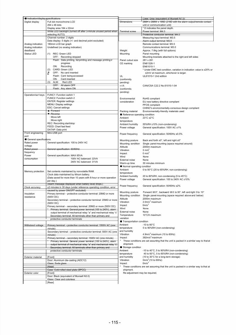
7/23/2019 AH4000 Multi General INE-851B (1)
http://slidepdf.com/reader/full/ah4000-multi-general-ine-851b-1 118/121
- 115 -
Indication/display specificationsDigital display Full dot monochrome LCD
264 x 48 dotsDisplay area 184 x 22mmWhite LED backlight (turned off after 3-minute unused period whenselecting AUTO)Channel number: 2 digitsData display: 5 digits (+/- and decimal point excluded)
Analog indication 180mm LCD bar graph Analog indicationdeadband
Undefined (no analog indication)
Status LED (1) REC: Green LEDOFF: Recording stoppedFlash: Data printing, list printing and message printing in
progressON: Recording
(2) CARD: Green LEDOFF: No card insertedFlash: Card being accessedON: Card inserted
(3) ALM: Red LEDOFF: All alarm OFFFlash: Any alarm ON
Operation/se t keys FUNC1: Function switch 1FUNC2: Function switch 2ENTER: Register settingsMENU: Display settingsESC: Cancel settings: Forward: Reverse
: Move left: Move right
REC: Recording start/stopFEED: Chart fast feedDATAP: Data print
Front engineeringport
Mini-USB port
General specificationsRated powervoltage
General specification: 100 to 240V AC
Rated powerfrequency
General specification: 50/60Hz
Powerconsumption
General specification: MAX 65VA100V AC balanced: 22VA240V AC balanced: 31VA
Memory protection Set contents maintained by nonvolatile RAM.Clock data maintained by lithium battery.(Data saved for more than 10 years with 8-hour or more operationper day.)(Alarm message displayed when battery level drops.)
Clock accuracy ±2 minutes in 30 days (under reference operating condition, errorcaused by power ON/OFF excluded)
Insulationresistance
Primary terminal – protective conductor terminal: 20MΩ or more(500V DC)Secondary terminal – protective conductor terminal: 20MΩ or more(500V DC)Primary terminal – secondary terminal: 20MΩ or more (500V DC)* Primary terminal: General power terminal (100 to 240V), alarm
output terminal of mechanical relay “a” and mechanical relay “c”Secondary terminal: All terminals other than primary andprotective conductor terminals
Withstand voltage Primary terminal – protective conductor terminal: 1500V AC (oneminute)Secondary terminal – protective conductor terminal: 500V AC (one
minute)Primary terminal – secondary terminal: 1500V AC (one minute)* Primary terminal: General power terminal (100 to 240V), alarm
output terminal of mechanical relay “a” and mechanical relay “c”Secondary terminal: All terminals other than primary andprotective conductor terminals
Exterior material [Front]Door: Aluminum die-casting (ADC12)Glass: Soda glass[Rear]Case: Cold-rolled steel plate (SPCC)
Exterior color [Front]Door: Black (equivalent of Munsell N3.0)Glass: Clear and colorless[Rear]
Case: Gray (equivalent of Munsell N7.0)Dimensions 288H x 288W x 195D (216D with the alarm output/remote contact
unit or communication unit)* D indicates the panel depth.
Terminal screw Power terminal: M4.0Protective conductor terminal: M4.0Measuring input terminal: M3.5
Alarm output terminal: M3.5Remote contact terminal: M3.5Communications terminal: M3.0
Weight Approx. 7.6kg (with full options)Mounting Panel mounting
Mounting brackets attached to the right and left sidesPanel cutout size 281 x 281CE marking EN61326-1
EN61010-1* Under EMC test condition, variation in indication value is ±20% or
±2mV at maximum, whichever is larger.UL(conformitypending)
UL61010-1 2nd edition
c-UL(conformitypending)
CAN/CSA C22.2 No.61010-1-04
Environmentalconsideration
RoHS compliantEU new battery directive compliantPFOS compliantCHINO‟s environmentally-conscious design compliant
Packing material Environmentally-friendly materials used
Reference operating condition
Ambienttemperature
23°C ±2°C
Ambient humidity 55%RH ±10% (non-condensing)Power voltage General specification: 100V AC ±1%
Power frequency General specification: 50/60Hz ±0.5%
Mounting posture Back and forth ±0°, left and right ±0°Mounting condition Single panel mounting (space required around)
Altitude 2000m maximumVibration 0 m/s2 Impact 0 m/s2 Wind NoneExternal noise NoneWarm-up time 30 minutes minimum
Normal operating condition Ambienttemperature
0 to 50°C (20 to 65%RH, non-condensing)
Ambient humidity 20 to 80%RH, non-condensing (5 to 45°C)Power voltage General specification: 100 to 240V AC ±10%
Power frequency General specification: 50/60Hz ±2%
Mounting posture Forward tilt 0°, backward tilt 0 to 30°, left and right 0 to 10°Mounting condition Single panel mounting (space required above and below)
Altitude 2000m maximumVibration 2.0m/s2 maximumImpact 0m/s2 Wind NoneExternal noise NoneTemperaturevariation
10°C/h maximum
Transportation condition Ambienttemperatureand humidity
-10 to 60°C5 to 90%RH (non-condensing)
Vibration 4.9m/s2
maximum (10 to 60Hz)Impact 392m/s2 maximum* These conditions are set assuming that the unit is packed in a similar way to that at
shipment.
Storage condition Ambienttemperatureand humidity
-10 to 40°C, 5 to 90%RH (non-condensing)40 to 60°C, 5 to 65%RH (non-condensing)
(10 to 30°C for a long-term storage)Vibration 0m/s2 (10 to 60Hz)Impact 0m/s2 * These conditions are set assuming that the unit is packed in a similar way to that at
shipment.Re-adjustment may be required.
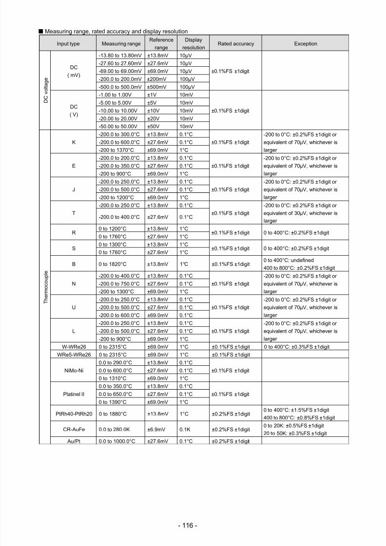
7/23/2019 AH4000 Multi General INE-851B (1)
http://slidepdf.com/reader/full/ah4000-multi-general-ine-851b-1 119/121
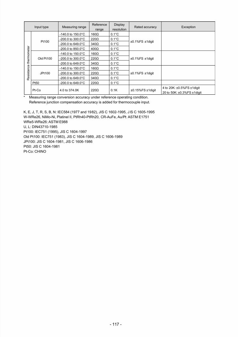
7/23/2019 AH4000 Multi General INE-851B (1)
http://slidepdf.com/reader/full/ah4000-multi-general-ine-851b-1 120/121
- 117 -
Input type Measuring rangeReference
range
Display
resolutionRated accuracy Exception
R e s
i s t a n c e
t h e r
m o m e
t e r
Pt100
-140.0 to 150.0°C 160Ω 0.1°C
±0.1%FS ±1digit-200.0 to 300.0°C 220Ω 0.1°C
-200.0 to 649.0°C 340Ω 0.1°C
-200.0 to 850.0°C 400Ω 0.1°C
Old Pt100
-140.0 to 150.0°C 160Ω 0.1°C
±0.1%FS ±1digit-200.0 to 300.0°C 220Ω 0.1°C-200.0 to 649.0°C 340Ω 0.1°C
JPt100
-140.0 to 150.0°C 160Ω 0.1°C
±0.1%FS ±1digit-200.0 to 300.0°C 220Ω 0.1°C
-200.0 to 649.0°C 340Ω 0.1°C
Pt50 -200.0 to 649.0°C 220Ω 0.1°C
Pt-Co 4.0 to 374.0K 220Ω 0.1K ±0.15%FS ±1digit4 to 20K: ±0.5%FS ±1digit
20 to 50K: ±0.3%FS ±1digit
* Measuring range conversion accuracy under reference operating condition.Reference junction compensation accuracy is added for thermocouple input.
K, E, J, T, R, S, B, N: IEC584 (1977 and 1982), JIS C 1602-1995, JIS C 1605-1995
W-WRe26, NiMo-Ni, Platinel II, PtRh40-PtRh20, CR-AuFe, Au/Pt: ASTM E1751WRe5-WRe26: ASTM E988U, L: DIN43710-1985Pt100: IEC751 (1995), JIS C 1604-1997Old Pt100: IEC751 (1983), JIS C 1604-1989, JIS C 1606-1989JPt100: JIS C 1604-1981, JIS C 1606-1986Pt50: JIS C 1604-1981Pt-Co: CHINO

7/23/2019 AH4000 Multi General INE-851B (1)
http://slidepdf.com/reader/full/ah4000-multi-general-ine-851b-1 121/121