Embed Size (px)
Citation preview

8/3/2019 AHIE-89CCB2_R0_EN
http://slidepdf.com/reader/full/ahie-89ccb2r0en 1/28
Installation
MGE™ Galaxy™ 3500in Parallel
10-40 kVA
380/400/415 V
10-30 kVA
208/220 V

8/3/2019 AHIE-89CCB2_R0_EN
http://slidepdf.com/reader/full/ahie-89ccb2r0en 2/28
8/3/2019 AHIE-89CCB2_R0_EN
http://slidepdf.com/reader/full/ahie-89ccb2r0en 3/28
Contents
MGE Galaxy 3500 10-40 kVA 380/400/415 V - 10-30 kVA - 208/220 V Installation in Parallel i
Safety ............................................................................... 1
IMPORTANT SAFETY INSTRUCTIONS- SAVE THESE INSTRUCTIONS. . . . . . . . . . . . . . . . . . . . . . . . . . . . . . 1
Prepare for Floor-Anchoring (optional) ........................ 2
System arrangements . . . . . . . . . . . . . . . . . . . . . . . . . . . . . . . . . . . . 2
Hole positions for a stand-alone UPS enclosure with L-shaped
anchoring brackets . . . . . . . . . . . . . . . . . . . . . . . . . . . . . . . . . . . . . . . 3
Hole positions for up to four UPS units in parallel with U-shaped
anchoring brackets. . . . . . . . . . . . . . . . . . . . . . . . . . . . . . . . . . . . . . . 4
Prepare for Parallel Communication Cables ................ 5
Three different ways of routing cables . . . . . . . . . . . . . . . . . . . . . . . 5
Schematic overview of the PBus cables layout . . . . . . . . . . . . . . . . 5
Remove the front panel . . . . . . . . . . . . . . . . . . . . . . . . . . . . . . . . . . . 6
Remove the top cover . . . . . . . . . . . . . . . . . . . . . . . . . . . . . . . . . . . . 7
Remove the batteries . . . . . . . . . . . . . . . . . . . . . . . . . . . . . . . . . . . . . 7
Install the interconnection plates (optional) . . . . . . . . . . . . . . . . . . 7
Run the Cables.............................................................. 10UPSs apart without Conduits and Interconnection . . . . . . . . . . . . . 10
UPSs bayed together without Conduits . . . . . . . . . . . . . . . . . . . . . . 12
UPSs apart or bayed together with Conduits. . . . . . . . . . . . . . . . . . 13
Final Mechanical Assembly ......................................... 15
Level the Enclosures (L-shaped Floor Anchoring Brackets)and Install Batteries . . . . . . . . . . . . . . . . . . . . . . . . . . . . . . . . . . . . . . 15
Level the enclosures with the leveling feet . . . . . . . . . . . . . . . . . . 15
Install battery-securing and floor-anchoring brackets . . . . . . . . . 16
Reinstall the Enclosure Plates. . . . . . . . . . . . . . . . . . . . . . . . . . . . . . 17
Reinstall the top cover and the front panel . . . . . . . . . . . . . . . . . . 17
8/3/2019 AHIE-89CCB2_R0_EN
http://slidepdf.com/reader/full/ahie-89ccb2r0en 4/28
MGE Galaxy 3500 10-40 kVA 380/400/415 V - 10-30 kVA - 208/220 V Installation in Parallelii
Power Connections (Overview). . . . . . . . . . . . . . . . . . . . . . . . . . . . . 18
3:3 - 380/400/415 V input - 380/400/415 V output . . . . . . . . . . . . . . 18
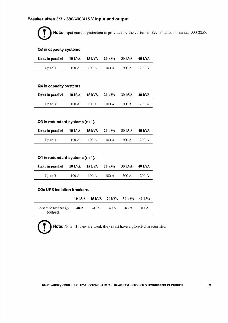
Breaker sizes 3:3 - 380/400/415 V . . . . . . . . . . . . . . . . . . . . . . . . . . . 19
3:3 - 208/220 V input - 208/220 V output . . . . . . . . . . . . . . . . . . . . . 20
Breaker sizes 3:3 - 208/220 V . . . . . . . . . . . . . . . . . . . . . . . . . . . . . . 21
3:1 - 380/400/415 V input - 220/230/240 V output . . . . . . . . . . . . . . 22
Breaker sizes 3:1 - 380/400/415 V . . . . . . . . . . . . . . . . . . . . . . . . . . . 23

8/3/2019 AHIE-89CCB2_R0_EN
http://slidepdf.com/reader/full/ahie-89ccb2r0en 5/28
1MGE Galaxy 3500 10-40 kVA 380/400/415 V - 10-30 kVA - 208/220 V Installation in Parallel
Safety
IMPORTANT SAFETY INSTRUCTIONS- SAVE THESE INSTRUCTIONS
Warning: ALL safety instructions in the Safety Sheet (990-2940) must be read,
understood and followed prior to installation. Failure to do so could result in equipment
damage, serious injury, or death.
Caution: All electrical power and power control wiring must be installed by a qualified
electrician, and must comply with local and national regulations for maximum power rating.
Note: The cables must be run by the electrician but not attached. The field service engineer
from APC by Schneider Electric will install the parallel communication box and attach all
cables to the UPSs.
Note: Up to four UPS units can run in parallel.
See also:For information on UPS specifications on the MGE™ Galaxy™ 3500 series, see part
numbers (available from the document storage in the UPS):
• 990-2258 — Installation 380/400/415 V
• 990-1957 — Installation 208/220 V
• 990-2387 — Installation 380/400/415 V (3:1)

8/3/2019 AHIE-89CCB2_R0_EN
http://slidepdf.com/reader/full/ahie-89ccb2r0en 6/28
MGE Galaxy 3500 10-40 kVA 380/400/415 V - 10-30 kVA - 208/220 V Installation in Parallel2
Prepare for Floor-Anchoring (optional)Note: If floor anchoring and battery securing is required, read this section. If not, see “Prepare
for Parallel Communication Cables” on page 5.
Note: Allow for enough working space behind the enclosure for electrical work to be carried
out (e.g. if you want to install a conduit box or if you want to connect an XR Battery Enclosure
at a later stage). Minimum rear clearance is 100 mm (3.93 in) and must comply with applicablenational and local codes. 600 mm (23.6 in) is recommended.
Note: The L-shaped floor anchoring brackets that secured the enclosure to the pallet during
shipment may be used for a stand-alone UPS enclosure to enhance stability. See this chapter for
hole positions and see also “Level the Enclosures (L-shaped Floor Anchoring Brackets) and
Install Batteries” on page 15. The L-shaped floor anchoring brackets are not necessary when
baying enclosures together. Instead, the three U-shaped floor anchoring brackets from the
baying kit are used.
Note: Hole positions are only intended as a guide.
System arrangements
APC recommends the following arrangements of UPS units and XR Battery Enclosures (XR) in parallel.
Examples with two parallel systems using baying kits.
Note: UPS units and their respective XR Battery Enclosure can be bayed together. XR
Battery Enclosures must never be shared in a parallel UPS system.
XRXR XR XRUPS XRXR XR XRUPS XRXR XR XRUPS XRXR XR XRUPS
XR XR XRXR XRXR XR XRUPSUPS

8/3/2019 AHIE-89CCB2_R0_EN
http://slidepdf.com/reader/full/ahie-89ccb2r0en 7/28
3MGE Galaxy 3500 10-40 kVA 380/400/415 V - 10-30 kVA - 208/220 V Installation in Parallel
Hole positions for a stand-alone UPS enclosure with L-shaped anchoring brackets
Note: Recommended minimum number of screws per enclosure for the L-shaped brackets is
four; one in each corner. Recommended floor bolt size: M8.
Model width: 352 mm (13.85 in) and 523 mm (20.59 in).
Note: Rear service clearance must comply with applicable national and local codes. 600 mm
(23.6 in) is recommended.
Conduit box (if applicable)
Floor anchoring hole
Minimum rear
clearance:100 mm (3.93 in)
8/3/2019 AHIE-89CCB2_R0_EN
http://slidepdf.com/reader/full/ahie-89ccb2r0en 8/28
MGE Galaxy 3500 10-40 kVA 380/400/415 V - 10-30 kVA - 208/220 V Installation in Parallel4
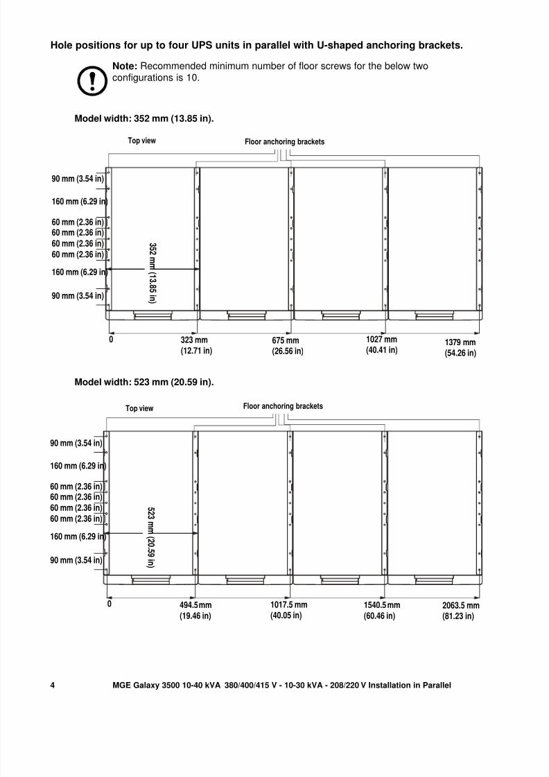
Hole positions for up to four UPS units in parallel with U-shaped anchoring brackets.
Note: Recommended minimum number of floor screws for the below twoconfigurations is 10.
Model width: 352 mm (13.85 in).
Model width: 523 mm (20.59 in).
Top view
90 mm (3.54 in)
160 mm (6.29 in)
60 mm (2.36 in)60 mm (2.36 in)
60 mm (2.36 in)
60 mm (2.36 in)
160 mm (6.29 in)
90 mm (3.54 in)
3 5 2 m m
( 1 3 . 8 5 i n )
0 323 mm
(12.71 in)675 mm(26.56 in)
1027 mm(40.41 in)
1379 mm(54.26 in)
Floor anchoring brackets
Top view
90 mm (3.54 in)
160 mm (6.29 in)
60 mm (2.36 in)60 mm (2.36 in)
60 mm (2.36 in)
60 mm (2.36 in)
160 mm (6.29 in)
90 mm (3.54 in)
5 2 3 m m (
2 0 . 5 9 i n )
0 494.5 mm
(19.46 in)
1017.5 mm(40.05 in)
1540.5 mm
(60.46 in)2063.5 mm(81.23 in)
Floor anchoring brackets

8/3/2019 AHIE-89CCB2_R0_EN
http://slidepdf.com/reader/full/ahie-89ccb2r0en 9/28
5MGE Galaxy 3500 10-40 kVA 380/400/415 V - 10-30 kVA - 208/220 V Installation in Parallel
Prepare for Parallel CommunicationCables
Three different ways of routing cables
Note: The enclosures in a parallel system can be kept apart, or they can be assembled with
interconnection plates. If the enclosures are kept apart, the communication cables can be run inconduits (if applicable).
The routing of cables between the UPSs can be done in three different ways.
1. UPSs apart (without conduits and without interconnection plates)
2. UPSs bayed together (without conduits and with interconnection plates)
3. UPSs apart or bayed together (with conduits and optional interconnection plates).
Schematic overview of the PBus cables layout
Note: The cables must be run by the electrician but not attached. The field service engineer
from APC by Schneider Electric will attach all cables to the UPS(s) and install the parallelcommunication box. The below is for overview only.
Note: The PBus cables run from UPS 1 to UPS 2 to UPS 3 to UPS 4 if your configuration
consists of 4 UPSs.
Note: The PBus cables are labelled PBus 1 and PBus 2.
Note: PBus 1 cables must be kept together and PBus 2 cables must be kept together. If you by
mistake run a cable between a PBUS1 terminal and a PBUS2 terminal you will be notified by
the display.
Note: If the configuration consists of only two UPS units, the terminators must be installed in
UPS 1 & 2. With three UPS units the terminators must be installed in UPS 1 & 3.

8/3/2019 AHIE-89CCB2_R0_EN
http://slidepdf.com/reader/full/ahie-89ccb2r0en 10/28
MGE Galaxy 3500 10-40 kVA 380/400/415 V - 10-30 kVA - 208/220 V Installation in Parallel6
This schematic overview shows the cable layout:
Remove the front panel
1. Use a coin or similar to turn the two black lock
devices on either side of the display in the direction of
each other to a vertical position.
2. Push the front panel upwards and pull it outwards
to disengage the locking device at the top of the
enclosure.
3. Lift the front panel free of the two slots at the
bottom of the enclosure.
Terminators
Pbus 2 cables( must be kept together)
Pbus 1 cables (must be kept together)
Model:
Serial:
BATTERYUNITModel:
Serial:
BATTERY UNIT
Model:
Serial:
BATTERYUNITModel:
Serial:
BATTERY UNIT
Model:
Serial:
BATTERYUNITModel:
Serial:
BATTERY UNIT
Model:
Serial:
BATTERYUNITModel:
Serial:
BATTERY UNIT
2
1
3

8/3/2019 AHIE-89CCB2_R0_EN
http://slidepdf.com/reader/full/ahie-89ccb2r0en 11/28
7MGE Galaxy 3500 10-40 kVA 380/400/415 V - 10-30 kVA - 208/220 V Installation in Parallel
Remove the top cover
1.Loosen the six screws of the top
cover (four at the front and two at
the back).
2.Lift up from the back and push
forward to free the cover.
3.Leave the cover unattached on
top of the UPS.
Remove the batteries
Note: See Operation manual 990-2386.
Install the interconnection plates (optional)
Note: If the UPS units are kept apart, the interconnection plates are irrelevant. Please instead
move to “Level the Enclosures (L-shaped Floor Anchoring Brackets) and Install Batteries” on
page 15 or use the U-shaped anchoring brackets (described below) for floor anchoring. If the
UPS units are kept together, please proceed with the below installation procedure of the
interconnection plates.
1.Remove the side panels from the enclosure(s)
to get access to the holes in the bottom frame.
Note: If the UPS system is going to be anchored to the floor, drilling holes for anchoring is
recommended to take place at this stage. See “Prepare for Floor-Anchoring (optional)” on
page 2.
1 1
1UPS 1 UPS 2
1

8/3/2019 AHIE-89CCB2_R0_EN
http://slidepdf.com/reader/full/ahie-89ccb2r0en 12/28
MGE Galaxy 3500 10-40 kVA 380/400/415 V - 10-30 kVA - 208/220 V Installation in Parallel8
Note: Make sure that the enclosures are level to be able to anchor the enclosures to each
other.
2. Position two U-
shaped floor
anchoring
brackets underone enclosure;
one in each
side.
Note: The U-shaped anchoring brackets are 1-2 mm higher than the opening below the
enclosure to inactivate the casters. Therefore, the enclosure must be tilted when placing the U-
shaped anchoring brackets under the enclosure.
3. In each side of the same enclosure insert a
maximum of nine and a minimum of two M8
screws (not provided) through holes in the
bottom of the enclosure and through holes in the
U-shaped floor anchoring brackets, and into the
pre-drilled floor holes.
4. Fasten the screws.
5. Move the adjacent enclosure on its
casters close to the enclosure with the U-
shaped floor anchoring brackets.
Front of enclosure
5
Front of adjacent
enclosure
2
2
:
U-shaped flooranchoring
bracket
7
3
4
:

8/3/2019 AHIE-89CCB2_R0_EN
http://slidepdf.com/reader/full/ahie-89ccb2r0en 13/28
9MGE Galaxy 3500 10-40 kVA 380/400/415 V - 10-30 kVA - 208/220 V Installation in Parallel
Note: If the adjacent enclosure is on its levelling feet, use a forklift or pallet jack to move it
into position.
6.Insert the interconnection plates
between the two enclosures. One is
positioned toward the front and the
other toward the rear. Note how the“wings” on the interconnection
plates rest in slots at the top of the
inner panel.
7.Align the two enclosures and level
the three marked rows of bolt holes
in UPS 1 with the holes in UPS 2.
8.Push the two enclosures firmly
together.
9.Bolt the two enclosures together, using
the six M6x25 mm screws and nuts
supplied in the kit; join one hole at the
front and one hole at the rear of the
enclosures on three levels.
10.Position the last and third U-shaped
floor anchoring bracket under the adjacent
enclosure (see previous graphics) and
insert a minimum of two floor anchoring
M8 screws (not provided) through holes
in the bottom of the enclosure and through
holes in the U-shaped floor anchoring
bracket, and into the predrilled floor
holes, and then fasten the screws.
6
8
77
77
77
UPS 1 UPS 2
9
9UPS 1 UPS 2
Back
Front
TopviewTopview

8/3/2019 AHIE-89CCB2_R0_EN
http://slidepdf.com/reader/full/ahie-89ccb2r0en 14/28
MGE Galaxy 3500 10-40 kVA 380/400/415 V - 10-30 kVA - 208/220 V Installation in Parallel10
Run the Cables
UPSs apart without Conduits and InterconnectionNote: If the UPS system is going to be anchored to the floor, drilling holes for anchoring is
recommended to take place at this stage. See “Prepare for Floor-Anchoring (optional)” on
page 2.
1. Remove the front panel if not already done under “Prepare for Parallel Communication Cables”
on page 5.
2. Loosen the two screws from the cable-inlet plates at the bottomxplate of UPS 1 and UPS 2, and
remove the plates.
Parallel
communication boxinstalled by field
service engineer fromAPC by Schneider
Electric
UPS 1UPS 2
7
3
4
4
27
8
5
7 2 8 7
6

8/3/2019 AHIE-89CCB2_R0_EN
http://slidepdf.com/reader/full/ahie-89ccb2r0en 15/28
11MGE Galaxy 3500 10-40 kVA 380/400/415 V - 10-30 kVA - 208/220 V Installation in Parallel
3. From UPS 1: Run the two PBus cables to the slots on thexleft side of the enclosure and down
inside the panel.
4. From the lowest slot fish out the cables from the side panel andxrun them down through the cable
inlet and through the round hole at the bottom.
5. Run the PBus cables to UPS 2 and to the slots on the left side of the enclosure, and up inside
thexpanel.
6. Fish out the PBus cables and leave them unattached to the parallel box.
7. Run the ABus cable from the Maintenance Bypass Panel to the slots on the left side of the
enclosure and up inside the panel the same way as for the PBus cables.
8. Reattach the cable-inlet covers.
9. Fasten the cables with cable ties.
Note: Proceed the routing of cables into UPS 3 and UPS 4, if applicable.

8/3/2019 AHIE-89CCB2_R0_EN
http://slidepdf.com/reader/full/ahie-89ccb2r0en 16/28
MGE Galaxy 3500 10-40 kVA 380/400/415 V - 10-30 kVA - 208/220 V Installation in Parallel12
UPSs bayed together without ConduitsNote: If the UPS system is going to be anchored to the floor, drilling holes for anchoring is
recommended to take place at this stage. See “Prepare for Floor-Anchoring (optional)” on
page 2.
Note: See “Install the interconnection plates (optional)” on page 7 for instructions on how to
assemble the enclosures with interconnection plates.
.
1. Remove the front panel and the top cover if not already done under “Prepare for Parallel
Communication Cables” on page 5.
2. Loosen the two screws from the cable-inlet plates at the bottomxplate of UPS 1 and UPS 2, and
remove the plates.
UPS 1
UPS 2
7
3
4
27 8
5
2 7
6
UPS 1
8

8/3/2019 AHIE-89CCB2_R0_EN
http://slidepdf.com/reader/full/ahie-89ccb2r0en 17/28
13MGE Galaxy 3500 10-40 kVA 380/400/415 V - 10-30 kVA - 208/220 V Installation in Parallel
3. From UPS 1: Run the two PBus cables to the slots on the left side of the enclosure and down
inside thexpanel.
4. From the lowest slot fish out the cables from the side panel, run the cables across and through the
cable inlets of thextwo side panels.
5. From the bottom of UPS 2, run the PBus cables to the slots onxthe left side of the enclosure and
up inside the panel.
6. Fish out the PBus cables and leave them unattached to the parallel box.
7. Run the ABus cable from the Maintenance Bypass Panel to the slots on the left side of the
enclosure and up inside the panel the same way as for the PBus cables.
8. Reattach the cable-inlet cover plates.
9. Fasten the cables with cable ties.
Note: Proceed the routing of cables into UPS 3 and UPS 4, if applicable.
UPSs apart or bayed together with ConduitsNote: If the UPS system is going to be anchored to the floor, drilling holes for anchoring is
recommended to take place at this stage. See “Prepare for Floor-Anchoring (optional)” on
page 2.
Note: When enclosures are assembled with interconnection plates and bolted together, the
PBus cables can be run inside the enclosures and then only the ABus cable has to be run in a
conduit (if applicable).
Note: See“Install the interconnection plates (optional)” on page 7 for instructions on how to
assemble the enclosures with interconnection plates.
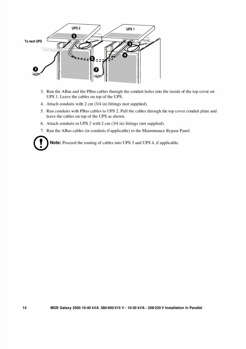
1.Remove the front panel and the top cover if not already
done under “Prepare for Parallel Communication Cables”
on page 5.
2.Remove the conduit plate at the back of the UPS cover
and drill holes with center in the small pre-drilled holes. 2
cm (3/4 in) is recommendable for conduits.
2
8/3/2019 AHIE-89CCB2_R0_EN
http://slidepdf.com/reader/full/ahie-89ccb2r0en 18/28

8/3/2019 AHIE-89CCB2_R0_EN
http://slidepdf.com/reader/full/ahie-89ccb2r0en 19/28
15MGE Galaxy 3500 10-40 kVA 380/400/415 V - 10-30 kVA - 208/220 V Installation in Parallel
Final Mechanical Assembly
Level the Enclosures (L-shaped Floor AnchoringBrackets) and Install Batteries
Note: The leveling feet and the L-shaped floor anchoring brackets (reuse of transportationbrackets) are used in some configurations instead of the optional U-shaped floor anchoring
brackets described earlier in this manual.
Level the enclosures with the leveling feet
Note: Verify that the installation has been electrically wired before setting the leveling feet.
Set the leveling feet to ensure that the UPS is completely horizontal when it is in its final operatingposition. Use the wrench shipped with the UPS to adjust all four leveling feet from the front to the back,
and from the left to the right, until the pads make solid contact with the floor. Use a bubble level to check
that the enclosure is horizontal.
Caution: To avoid equipment damage, do not push or pull the UPS after the leveling feet
have been lowered.
.

8/3/2019 AHIE-89CCB2_R0_EN
http://slidepdf.com/reader/full/ahie-89ccb2r0en 20/28
MGE Galaxy 3500 10-40 kVA 380/400/415 V - 10-30 kVA - 208/220 V Installation in Parallel16
Install battery-securing and floor-anchoring brackets
1. Install the batteries by pushing them all the way into the enclosure.
2. If required, install the battery securing brackets to hold the batteries firmly in place. Note! Do not
install the bracket the same way they were positioned when the enclosure arrived. Rotate the
brackets 180º and reinstall.
Note: Battery securing brackets are delivered with the UPS or XR Battery Enclosure and
installed in front of the batteries. Extra battery securing brackets for additional batteries can be
purchased. Refer to kit SUVTOPT003: APC Smart-UPS VT Battery Lock Kit for one Battery
Module (two batteries).
3. Install the L-shaped floor-anchoring bracket (reuse of transportation brackets) by adding four M6
screws and nuts (provided) to the enclosure (only if the optional U-shaped floor anchoring
brackets described in this manual have not been chosen).
Note: If the floor has not been prepared for anchoring, see “Prepare for Floor-Anchoring(optional)” on page 2.
4. Drill floor holes.
5. Add a minimum of two M8 screws (not provided) to the anchoring bracket and tighten the screws
to the floor.
Battery securing bracket
L-shaped floor-anchoringbracket (reuse of
transportation bracket)
3
5
1
2

8/3/2019 AHIE-89CCB2_R0_EN
http://slidepdf.com/reader/full/ahie-89ccb2r0en 21/28
17MGE Galaxy 3500 10-40 kVA 380/400/415 V - 10-30 kVA - 208/220 V Installation in Parallel
Reinstall the Enclosure Plates
Reinstall the top cover and the front panel
1. Reinstall the top cover by fastening the four screws at the front and the two screws at the back.
2. Insert the two taps at the bottom of the front panel into the two slots at the bottom of the
enclosure.
3. Push the front panel forward until it engages the locking devices at the top of the enclosure.
4. Use a screwdriver to set the lock mechanism to the locked position.
Model:
Ser ial:
BATTERY UNIT Model:
Serial:
BATTERY UNIT
Model:
Serial:
BATTERY UNIT Model:
Serial:
BATTERY UNIT
Model:
Serial:
BATTERY UNITModel:
Serial:
BATTERYUNIT
Model:
Serial:
BATTERY UNITModel:
Serial:
BATTERYUNIT
22
3
44
8/3/2019 AHIE-89CCB2_R0_EN
http://slidepdf.com/reader/full/ahie-89ccb2r0en 22/28
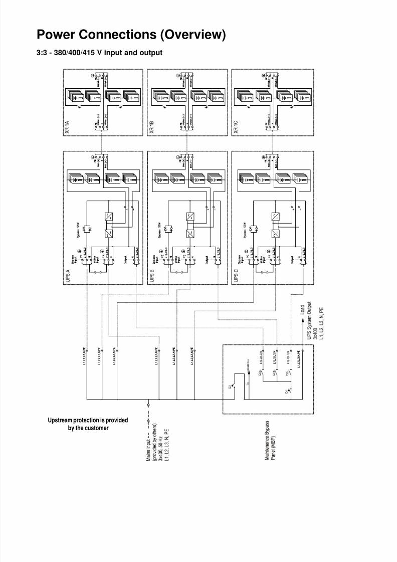
Power Connections (Overview)
3:3 - 380/400/415 V input and output
I / O M
B P C A N
I / O B
O A R D S
Q 3
Q 2 a
Q 2 b
Q 2 c
T o
Q 4
Upstream protection is provided
by the customer
8/3/2019 AHIE-89CCB2_R0_EN
http://slidepdf.com/reader/full/ahie-89ccb2r0en 23/28

8/3/2019 AHIE-89CCB2_R0_EN
http://slidepdf.com/reader/full/ahie-89ccb2r0en 24/28
MGE Galaxy 3500 10-40 kVA 380/400/415 V - 10-30 kVA - 208/220 V Installation in Parallel20
3:3 - 208/220 V input andoutput
.
I / O B o a r d
Q 2 a
Q 2 b
Q 2 c
T o
Q 4
Q 3
B y p a s s
I n p u t P
E L 1 , L 2 , L 3
N P E
L 1 , L 2 , L 3
N L 1 , L 2 , L 3
N
B y p a s s S S W
O u t p u t
P E
B a t t ( + )
N
B a t t ( - )
B y p a s s
I n p u t P
E L 1 , L 2 , L 3
N P E
L 1 , L 2 , L 3
N L 1 , L 2 , L 3
N
B y p a s s S S W
O u t p u t
P E
B a t t ( + )
N
B a t t ( - )
B y p a s s
I n p u t P
E L 1 , L 2 , L 3
N P E
L 1 , L 2 , L 3
N L 1 , L 2 , L 3
N
B y p a s s S S W
O u t p u t
P E
B a t t ( + )
N
B a t t ( - )
M a i n s
I n p u t
M a i n s
I n p u t
M a i n s
I n p u t
P E X R B a t t ( + )
N X R B a t t ( - )
P E
X R B a t t ( + )
N X R B a t t ( - )
P E
X R B a t t ( + )
N X R B a t t ( - )
P E
X R B a t t ( + ) N
X R B a t t ( - )
P E
X R B a t t ( + ) N
X R B a t t ( - )
P E
X R B a t t ( + ) N
X R B a t t ( - )
Upstream protection is providedby the customer

8/3/2019 AHIE-89CCB2_R0_EN
http://slidepdf.com/reader/full/ahie-89ccb2r0en 25/28
21MGE Galaxy 3500 10-40 kVA 380/400/415 V - 10-30 kVA - 208/220 V Installation in Parallel
Breaker sizes 3:3 - 208/220 V input and output
Note: Input current protection is provided by the customer. See Installation manual 990-1957.
Q3 in capacity systems.
Q4 in capacity systems.
Q3 in redundant systems (n+1).
Q4 in redundant systems (n+1).
Q2x UPS isolation breakers.
Units in parallel 10 kVA 15 kVA 20 kVA 30 kVA
Up to 3 175 A 175 A 350 A 350 A
Units in parallel 10 kVA 15 kVA 20 kVA 30 kVA
Up to 3 175 A 175 A 350 A 350 A
Units in parallel 10 kVA 15 kVA 20 kVA 30 kVA
Up to 3 175 A 175 A 350 A 350 A
Units in parallel 10 kVA 15 kVA 20 kVA 30 kVA
Up to 3 175 A 175 A 350 A 350 A
10 kVA 15 kVA 20 kVA 30 kVA
Load side breaker Q2 (output) 60 A 60 A 125 A 125 A
8/3/2019 AHIE-89CCB2_R0_EN
http://slidepdf.com/reader/full/ahie-89ccb2r0en 26/28
MGE Galaxy 3500 10-40 kVA 380/400/415 V - 10-30 kVA - 208/220 V Installation in Parallel22
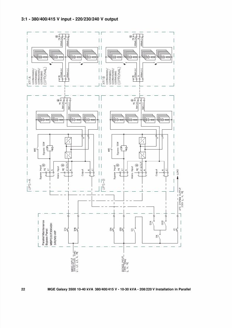
3:1 - 380/400/415 V input - 220/230/240 V output

8/3/2019 AHIE-89CCB2_R0_EN
http://slidepdf.com/reader/full/ahie-89ccb2r0en 27/28
23MGE Galaxy 3500 10-40 kVA 380/400/415 V - 10-30 kVA - 208/220 V Installation in Parallel
Breaker sizes 3:1 - 380/400/415 V input - 220/230/240 V output
Q1a, Q1b in redundant systems (1+1).
Q2a, Q2b in redundant systems (1+1).
Q3 in redundant systems (1+1).
Q4 in redundant systems (1+1).
Q5a, Q5b in redundant systems (1+1).
Units in parallel 15 kVA 20 kVA 30 kVA 40 kVA
2 25 A 35 A 50 A 63 A
Units in parallel 15 kVA 20 kVA 30 kVA 40 kVA
2 80 A 100 A 160 A 200 A
Units in parallel 15 kVA 20 kVA 30 kVA 40 kVA
2 80 A 100 A 160 A 200 A
Units in parallel 15 kVA 20 kVA 30 kVA 40 kVA
2 80 A 100 A 160 A 200 A
Units in parallel 15 kVA 20 kVA 30 kVA 40 kVA
2 80 A 100 A 160 A 200 A

8/3/2019 AHIE-89CCB2_R0_EN
http://slidepdf.com/reader/full/ahie-89ccb2r0en 28/28
APC Worldwide Customer Support
Customer support for this or any other APC product is available at no charge in any of the following ways:
• Visit the APC Web site to access documents in the APC Knowledge Base and to submit customer
support requests.
– www.apc.com (Corporate Headquarters)Connect to localized APC Web sites for specific countries, each of which provides customer support
information.
– www.apc.com/support/
Global support searching APC Knowledge Base and using e-support.
• Contact the APC Customer Support Center by telephone or e-mail.
– Local, country-specific centers: go to www.apc.com/support/contact for contact information.
For information on how to obtain local customer support, contact the APC representative or other distributors
from whom you purchased your APC product.
© 2011 APC by Schneider Electric. APC, the APC logo, and Smart-UPS are owned by Schneider Electric
Industries S.A.S., American Power Conversion Corporation, or their affiliated companies. All other
trademarks are property of their respective owners.