Embed Size (px)
Citation preview
INTERNATIONAL JOURNAL of ENGINEERING TECHNOLOGIES-IJET Şahin, et al, Vol.6, No.2, 2020
13
Secure and Fast Encryption Routine+: Evaluation by
Software Application
M. Faruk Şahin*, Musaria K. Mahmood*, Indrit Myderrizi*
*Department of Electric & Electronics Engineering, Faculty of Engineering and Architecture, İstanbul Gelisim University,
Istanbul, Turkey
([email protected], [email protected], [email protected])
‡ Musaria K. Mahmood; Indrit Myderrizi, Tel: +90 212 422 70 00,
Received: 20.06.2020 Accepted: 24.08.2020
Abstract- Nowadays, the Internet era and its components are based on the collection, exchange, and storage of information
which represent a sever security concern. Many cipher algorithms have been developed, evaluated, and implemented to increase
the protection of data for various applications. The most known strategy of data securing has been the implementation of
symmetrical key encryption standards. Secrecy, robustness, reliability, and software/ hardware implementation, are among the
most important properties of good cipher standard. In this work, text, data and image encryption/decryption are performed by a
MATLAB software implementation of the symmetric key block standard realized using the Secure and Fast Encryption Routine
(SAFER+) algorithm with 128 key length option. The results show good performances in encryption/ decryption speed through
a set of original procedures to simplify the achievement of nonlinear functions adopted by SAFER+ structure.
Keywords- SAFER+; data security; MATLAB; cryptology;
1. Introduction
The rapid development of data transmission in various fields
including education, banking, military, industrial and many
other fields has made cryptography and data security as the
main stone in all information systems. The evulotion of the
Internet toward the Internet of Thing (IoT), and The Internet
of Everything (IoE) has promoted the need of secure and
delay-free communication [1, 2]. Information and
confidentiality has become one of the most important and
urgent requirements in today's systems. Various encryption
algorithms developed through the science of cryptography are
used today for securing data exchange between different
INTERNATIONAL JOURNAL of ENGINEERING TECHNOLOGIES-IJET Şahin, et al, Vol.6, No.2, 2020
14
parties. The encryption systems fall into two categories, the
asymmetric and symmetric key encryption standards [3]. The
asymmetric encryption algorithms provide two different keys,
one for encryption usually available and known by all parties
and the second key for decryption which is known by the
owner and kept secret. The encryption key is the public key
while that used for decryption is the private key. Diffie-
Helman, RSA are examples of asymmetric encryptions [4].
Symmetric encryption algorithms use one secret key shared by
both parties (sender and receiver) for data encryption/
decryption. Along with the secret texts exchange, the
symmetrical keys must also be updated every predefined
period of time through securet sharing system usually based
on asymerical key standard. The plaintext (data) and the
symmetric key are the inputs of the system while the encrypted
message is the output. In the receiver side the reverse process
is planned by injecting the encrypted data with the same key
into the decryption system to reproduce the original plaintext.
Many symmetrical encryption standards exist today such as
the Data Encryption Standard (DES), Triple Data Encryption
Standard (3DES) [4], Blowfish [5], Secure And Fast
Encryption Routine (SAFER+) [6], and the Rijndael which is
selected by the U.S. National Institute of Standards and
Technology (NIST) as the actual Advanced Encryption
Standard (AES) since 2001 [7, 8]. Symmetric key encryption
standards are divided into two types; the block and stream
encryption algorithms. The block ciphers encrypt/ decrypt
fixed long length blocks of data, whereas the stream cipher is
operating by combining plaintext digits with a pseudorandom
keystream resulting on encryption of short data characters.
One of the most important advantages of symmetric key
encryption is its high speed compared to the asymmetric key
encryption, which make it suitable for real time applications.
Added to that, it is much easier to implement the symmetric
key algorithm on hardware using digital electronic gates based
on the repetition of elementary mathematical operations [9].
SAFER+ is the new algorithm of the SAFER family designed
by James Messey in Cylink. It is one of the symmetric key
algorithms known by its performance in data encryption
speed that makes it suitable for real-time data encryption
requirements. SAFER+ offers high efficiency and low
memory requirement compared to other algorithms [10].
SAFER+ is the most used encryption standard in the Bluetooth
security architecture. The confrontation of SAFER+ standard
with existing encryption algorithms proves its superiority in
Bluetooth algorithms, but this encryption system is also used
in other fields [11]. Its digital VLSI design and FPGA
implementation shows an outstanding performance in terms of
minimization of delay which enables this algorithm to be
utilized for high-speed applications [12, 13]. The software
implementation of the algorithm confirms its speed quality for
various case studies including speech, image and data in
general. While moving from theory to practice, the parts that
are hard to handle in software implementation are nonlinear
functions that must be solved by inventory procedure [14].
2. SAFER+ encryption/ decryption philosophy
2.1 General
SAFER encryption/ decryption family is byte oriented cipher
algorithm acting over a predefined data block size which is a
very advantageous situation for 8 bit microprocessors.
SAFER+ is a block cipher encrypting 16-byte (128 bits) data
blocks through a number of encryption/decryption cycles. The
INTERNATIONAL JOURNAL of ENGINEERING TECHNOLOGIES-IJET Şahin, et al, Vol.6, No.2, 2020
15
number of encryption/ decryption cycles is connected to the
key lengths which comes in three options [10]:
Key length equal to 128 bits yields an encryption/
decryption processes with 𝑅 = 8 rounds,
Key length equal to 192 bits yields an encryption/
decryption processes with 𝑅 = 12 rounds,
Key length equal to 256 bits yields an encryption/
decryption processes with 𝑅 = 16 rounds.
Starting from the original secrete symmetric key (𝐾1) as input,
a group of 2𝑅 keys (𝐾2 …𝐾2𝑅+1) is generated, each with the
same length as the original key, by the key schedule
subroutine. SAFER+ is composed by many encryption/
decryption layers (linears and nonlinears) based on byte
addition, bit addition, logarithm, exponential, matrix
multiplication, bits rotating, and many other funtions and
procedures. In this research paper, the SAFER+ cipher
algorithm with the option of 128-bit key length is adopted.
2.2 Additive groups
The group operations used in the encryption/ decryption
rounds consists of the interaction between the subkeys and a
16-byte data groups. Eight of data groups are subject to normal
arithmetic byte addition modulo 256 (add) while the other
eight bytes are bit-by-bit added modulo 2 with their peer bytes
in the subkeys (xor). Note that for the decryption rounds, a
byte- by-byte subtraction function (sub) is used instead of the
add function to reverse the data generation process.
Implementing two different group operations between the
subkeys and the data increases the degree of robustness of the
cipher protocol by consolidating the randomness and the
ambiguity of the resulting ciphertext. The add/sub, and xor
operations are performed two-by-two in a sequential manner,
and in the opposite locations for the decryption process
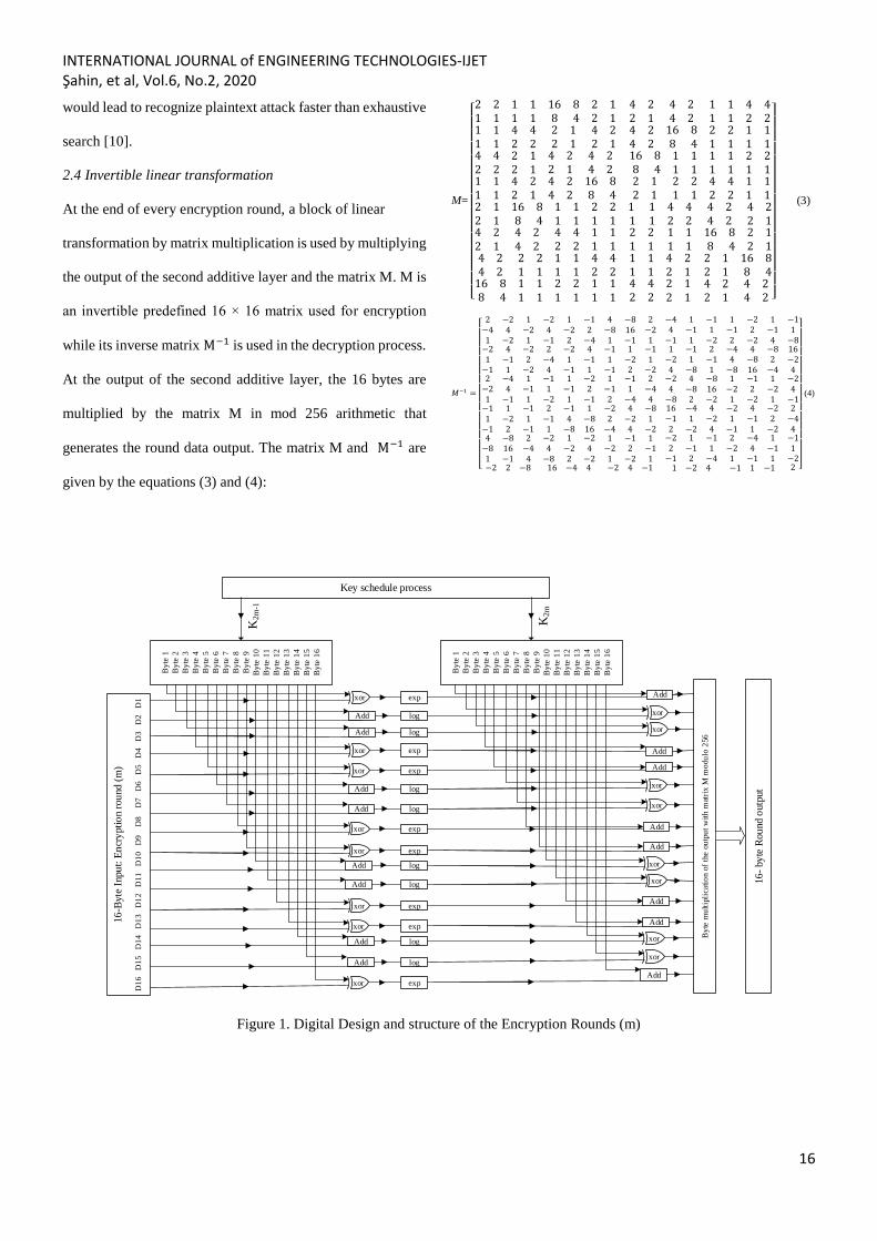
compared to the encryption process. At each encryption round,
two subkeys are used in two consecutive encryption layers,
where the bit-by-bit modulo 2 and byte-addition modulo 256
operations take place between subkeys and data as depicted in
the Fig. 1.
2.3 Nonlinear layers: Exponential and Logarithmic functions
A nonlinear encryption layer is used at each encryption/
decryption round based on two anti-functions; the exponential
and the logarithmic functions. It is the most difficult part in
the program implementation due to the limitation of software
tools when dealing with big numbers exceeding their memory
limits. This constraint is resolved in this work by providing an
original procedure called the Exponential Logarithmic
Function (ELF) which is used to resolve the mathematical
calculations. ELF operates at each round in the encryption/
decryption procedures between the two additive layers. The
exponential and logarithmic fuctions in the ELF are defined
according to the base 45 such that:
Exponential function
For 0 ≤ 𝑥 ≤ 255, we have:
𝐹(𝑥) = {45𝑥 𝑚𝑜𝑑 257 𝑖𝑓 𝑥 ≠ 1280 𝑖𝑓 𝑥 = 128
(1)
Logarithmic function
For 0 ≤ 𝑦 ≤ 255, we have:
𝐺(𝑦) = {𝑙𝑜𝑔45(𝑦) 𝑖𝑓 𝑦 ≠ 0128 𝑖𝑓 𝑦 = 0
(2)
It is proven that the choice of exponential and logarithmic as
the two mutually inverse functions in this algorithm is a
distinctive choice because of substantial fraction of all
mutually inverse nonlinear functions when used in their place
INTERNATIONAL JOURNAL of ENGINEERING TECHNOLOGIES-IJET Şahin, et al, Vol.6, No.2, 2020
16
would lead to recognize plaintext attack faster than exhaustive
search [10].
2.4 Invertible linear transformation
At the end of every encryption round, a block of linear
transformation by matrix multiplication is used by multiplying
the output of the second additive layer and the matrix M. M is
an invertible predefined 16 × 16 matrix used for encryption
while its inverse matrix M−1 is used in the decryption process.
At the output of the second additive layer, the 16 bytes are
multiplied by the matrix M in mod 256 arithmetic that
generates the round data output. The matrix M and M−1 are
given by the equations (3) and (4):
M=
[ 2 21 1
1 11 1
1 11 1
4 42 2
16 88 4
2 12 1
2 12 1
4 22 1
4 42 2
2 12 1
1 11 1
4 22 1
4 22 1
4 24 2
4 24 2
16 88 4
4 22 1
4 24 2
4 24 2
16 88 4
1 11 1
4 42 2
2 21 1
1 11 1
16 88 4
1 11 1
2 12 1
2 21 1
1 11 1
2 21 1
4 42 2
1 11 1
2 12 1
16 88 4
4 22 1
4 24 2
1 11 1
2 21 1
4 42 2
1 11 1
4 24 2
2 21 1
16 88 4
1 11 1
1 11 1
4 42 2
2 21 1
1 11 1
1 11 1
4 42 2
2 21 1
1 11 1
4 24 2
4 22 1
16 88 4
2 12 1
1 11 1
4 22 1
4 42 2
2 12 1
2 12 1
16 88 4
4 22 1
4 24 2 ]
(3)
𝑀−1 =
[
2 −2 1−4 4 −21 −2 1
−2 1 −14 −2 2
−1 2 −4
4 −8 2−8 16 −21 −1 1
−2 4 −21 −1 2
−1 1 −2
2 −2 4−4 1 −14 −1 1
−1 1 −11 −2 1
−1 2 −22 −4 1
−2 4 −11 −1 1
−1 1 −21 −1 2
−2 1 −1
1 −1 2−1 1 −42 −4 4
−4 1 −14 −1 1
−1 1 −2
1 −2 1−1 2 −12 −2 4
−11
−81 −1 2
−2 1 −14 −8 1
−4 4 −84 −8 2
−8 16 −4
16−24
−2 4 −84 −8 16
−8 2 −2
1 −1 1−2 2 −21 −2 1
−24
−1−1 1 −11 −2 1
−1 2 −1
2 −1 1−1 4 −81 −8 16
−2 4 −82 −2 1
−4 4 −24 −8 2
−8 16 −41 −1 4
−2 1 −24 −2 4
−8 2 −2
1 −1 1−2 2 −11 −2 1
−2 2 −8 16 −4 4 −2 4 −1
16 −4 4−1 1 −22 −2 4
−2 4 −21 −1 2
−1 1 −2
2−44
−2 1 −12 −1 1
−1 2 −4
2 −4 1−2 4 −11 −1 1
−11
−21 −2 4 −1 1 −1 2 ]
(4)
xor
xor
xor
Add
Add
By
te 1
By
te 2
By
te 3
By
te 4
By
te 5
By
te 6
By
te 7
By
te 8
By
te 9
By
te 1
0
By
te 1
1
By
te 1
2
By
te 1
3
By
te 1
4
By
te 1
5
By
te 1
6
xor
xor
Add
Add
xor
Add
Add
xor
xor
Add
Add
log
exp
log
exp
log
exp
log
exp
log
exp
log
exp
log
exp
log
exp
By
te 1
By
te 2
By
te 3
By
te 4
By
te 5
By
te 6
By
te 7
By
te 8
By
te 9
By
te 1
0
By
te 1
1
By
te 1
2
By
te 1
3
By
te 1
4
By
te 1
5
By
te 1
6
xor
xor
xor
Add
Add
xor
xor
Add
Add
xor
Add
Add
xor
xor
Add
Add
By
te m
ult
ipli
cati
on o
f th
e o
utp
ut
wit
h m
atri
x M
mo
du
lo 2
56
16
- by
te R
ou
nd o
utp
ut
16
-Byte
Inpu
t: E
ncr
ypti
on r
ou
nd (
m)
D1
6
D1
5
D1
4
D1
3
D1
2
D1
1
D1
0
D9
D8
D7
D
6 D
5 D
4 D
3 D
2 D
1
Key schedule process
K2m
-1
K2m
Figure 1. Digital Design and structure of the Encryption Rounds (m)
INTERNATIONAL JOURNAL of ENGINEERING TECHNOLOGIES-IJET Şahin, et al, Vol.6, No.2, 2020
17
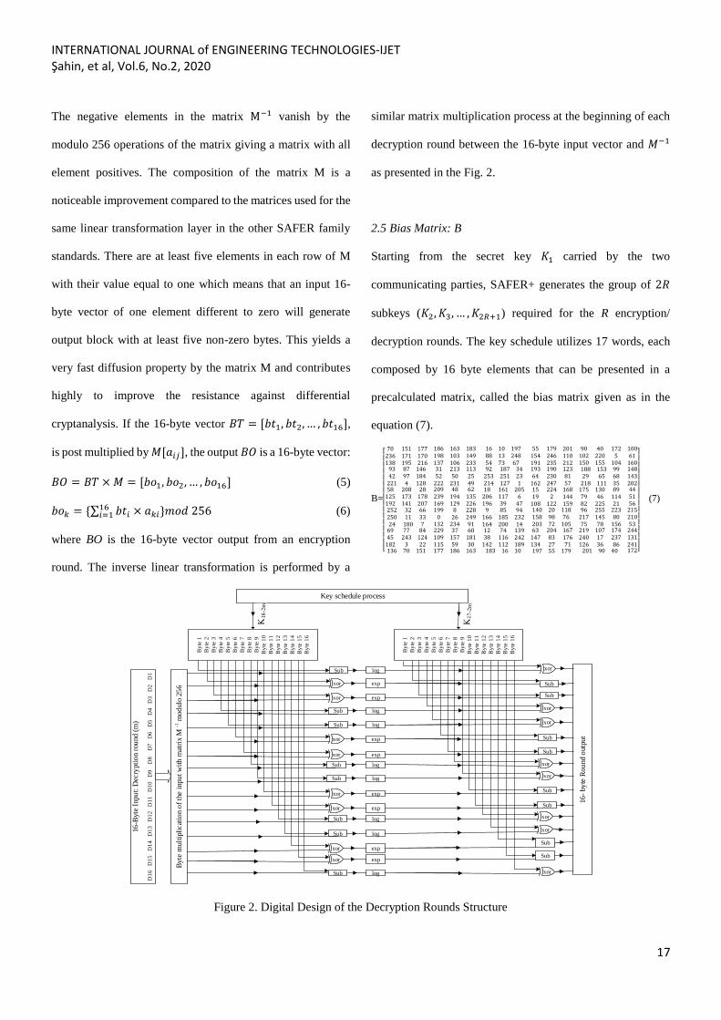
The negative elements in the matrix M−1 vanish by the
modulo 256 operations of the matrix giving a matrix with all
element positives. The composition of the matrix M is a
noticeable improvement compared to the matrices used for the
same linear transformation layer in the other SAFER family
standards. There are at least five elements in each row of M
with their value equal to one which means that an input 16-
byte vector of one element different to zero will generate
output block with at least five non-zero bytes. This yields a
very fast diffusion property by the matrix M and contributes
highly to improve the resistance against differential
cryptanalysis. If the 16-byte vector 𝐵𝑇 = [𝑏𝑡1, 𝑏𝑡2, … , 𝑏𝑡16],
is post multiplied by 𝑀[𝑎𝑖𝑗], the output 𝐵𝑂 is a 16-byte vector:
𝐵𝑂 = 𝐵𝑇 × 𝑀 = [𝑏𝑜1, 𝑏𝑜2, … , 𝑏𝑜16] (5)
𝑏𝑜𝑘 = {∑ 𝑏𝑡𝑖 × 𝑎𝑘𝑖}𝑚𝑜𝑑 25616𝑖=1 (6)
where BO is the 16-byte vector output from an encryption
round. The inverse linear transformation is performed by a
similar matrix multiplication process at the beginning of each
decryption round between the 16-byte input vector and 𝑀−1
as presented in the Fig. 2.
2.5 Bias Matrix: B
Starting from the secret key 𝐾1 carried by the two
communicating parties, SAFER+ generates the group of 2𝑅
subkeys (𝐾2, 𝐾3, … , 𝐾2𝑅+1) required for the R encryption/
decryption rounds. The key schedule utilizes 17 words, each
composed by 16 byte elements that can be presented in a
precalculated matrix, called the bias matrix given as in the
equation (7).
B=
[ 70 151 177236 171 170138 195 216
186 163 183198 103 149137 106 233
16 10 19788 13 24854 73 67
93 87 14642 97 184221 4 128
31 213 11352 50 25222 231 49
92 187 34253 251 23214 127 1
58 208 28125 173 178192 141 207
209 48 62239 194 135169 129 226
18 161 205206 117 6196 39 47
55 179 201154 246 110191 235 212
90 40 172102 220 5150 155 104
10061160
193 190 12364 230 81162 247 57
188 153 9929 65 68218 111 35
148143202
15 224 16819 2 144108 122 159
175 130 8979 46 11482 225 21
445156
252 32 66250 11 3324 180 7
199 8 2280 26 249
132 234 91
9 85 94166 185 232164 200 14
69 77 8445 243 124182 3 22
229 37 60109 157 181115 59 30
12 74 13938 116 242142 112 189
136 70 151 177 186 163 183 16 10
140 20 118158 98 76203 72 105
96 255 223217 145 8075 78 156
21521053
63 204 167147 83 176134 27 71
219 107 174240 17 237126 36 86
244131241
197 55 179 201 90 40 172]
(7)
xor
xor
xor
Sub
Sub
By
te 1
By
te 2
By
te 3
By
te 4
By
te 5
By
te 6
By
te 7
By
te 8
By
te 9
By
te 1
0
By
te 1
1
By
te 1
2
By
te 1
3
By
te 1
4
By
te 1
5
By
te 1
6
xor
xor
Sub
Sub
xor
Sub
Sub
xor
xor
Sub
Sub
log
exp
log
exp
log
exp
log
exp
log
exp
log
exp
log
exp
log
exp
By
te 1
By
te 2
By
te 3
By
te 4
By
te 5
By
te 6
By
te 7
By
te 8
By
te 9
By
te 1
0
By
te 1
1
By
te 1
2
By
te 1
3
By
te 1
4
By
te 1
5
By
te 1
6
xor
xor
xor
Sub
Sub
xor
xor
Sub
Sub
xor
Sub
Sub
xor
xor
Sub
Sub
Byte
mult
ipli
cat
ion o
f th
e i
npu
t w
ith
mat
rix M
-1 m
od
ulo
25
6
16
- by
te R
ou
nd o
utp
ut
16
-Byte
Inpu
t: D
ecry
pti
on r
ou
nd (
m)
D1
6
D1
5
D1
4
D1
3
D1
2
D1
1
D1
0
D9
D8
D7
D
6 D
5 D
4 D
3 D
2 D
1
Key schedule process
Figure 2. Digital Design of the Decryption Rounds Structure
INTERNATIONAL JOURNAL of ENGINEERING TECHNOLOGIES-IJET Şahin, et al, Vol.6, No.2, 2020
18
Bias matrix is used to randomize the key schedules and is
composed of a number of rows equal to the subkeys number
(including 𝐾1), thus 2𝑅 + 1 rows and 2𝑅 columns. The first
row is a dummy one because the key 𝐾1 already exists, so it is
not included in the matrix given in Eq (7). The bias matrix
𝐵[𝑏𝑖𝑗] is generated by the formula:
𝑏𝑖𝑗 = 45(4517𝑖+𝑗𝑚𝑜𝑑 257)𝑚𝑜𝑑 257 (8)
where by definition Eq (8) gives a result equal to 256, if the
𝑏𝑖𝑗 is set to zero. For the option adopted by this work with a
key equal to 16 bytes, 𝑖 = [2, 3, … , 17], and 𝑗 = [1, 2, … , 16].
3. Encryption/ Decryption Subroutines
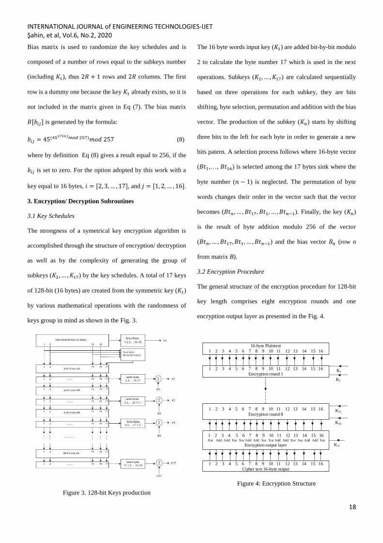
3.1 Key Schedules
The strongness of a symetrical key encryption algorithm is
accomplished through the structure of encryption/ dectryption
as well as by the complexity of generating the group of
subkeys (𝐾2, … , 𝐾17) by the key schedules. A total of 17 keys
of 128-bit (16 bytes) are created from the symmetric key (𝐾1)
by various mathematical operations with the randomness of
keys group in mind as shown in the Fig. 3.
Figure 3. 128-bit Keys production
The 16 byte words input key (𝐾1) are added bit-by-bit modulo
2 to calculate the byte number 17 which is used in the next
operations. Subkeys (𝐾2, … , 𝐾17) are calculated sequentially
based on three operations for each subkey, they are bits
shifting, byte selection, permutation and addition with the bias
vector. The production of the subkey (𝐾𝑛) starts by shifting
three bits to the left for each byte in order to generate a new
bits patern. A selection process follows where 16-byte vector
(𝐵𝑡1,…, 𝐵𝑡16) is selected among the 17 bytes sink where the
byte number (𝑛 − 1) is neglected. The permutation of byte
words changes their order in the vector such that the vector
becomes (𝐵𝑡𝑛 , … , 𝐵𝑡17, 𝐵𝑡1, … , 𝐵𝑡𝑛−1). Finally, the key (𝐾𝑛)
is the result of byte addition modulo 256 of the vector
(𝐵𝑡𝑛, … , 𝐵𝑡17, 𝐵𝑡1, … , 𝐵𝑡𝑛−1) and the bias vector 𝐵𝑛 (row n
from matrix B).
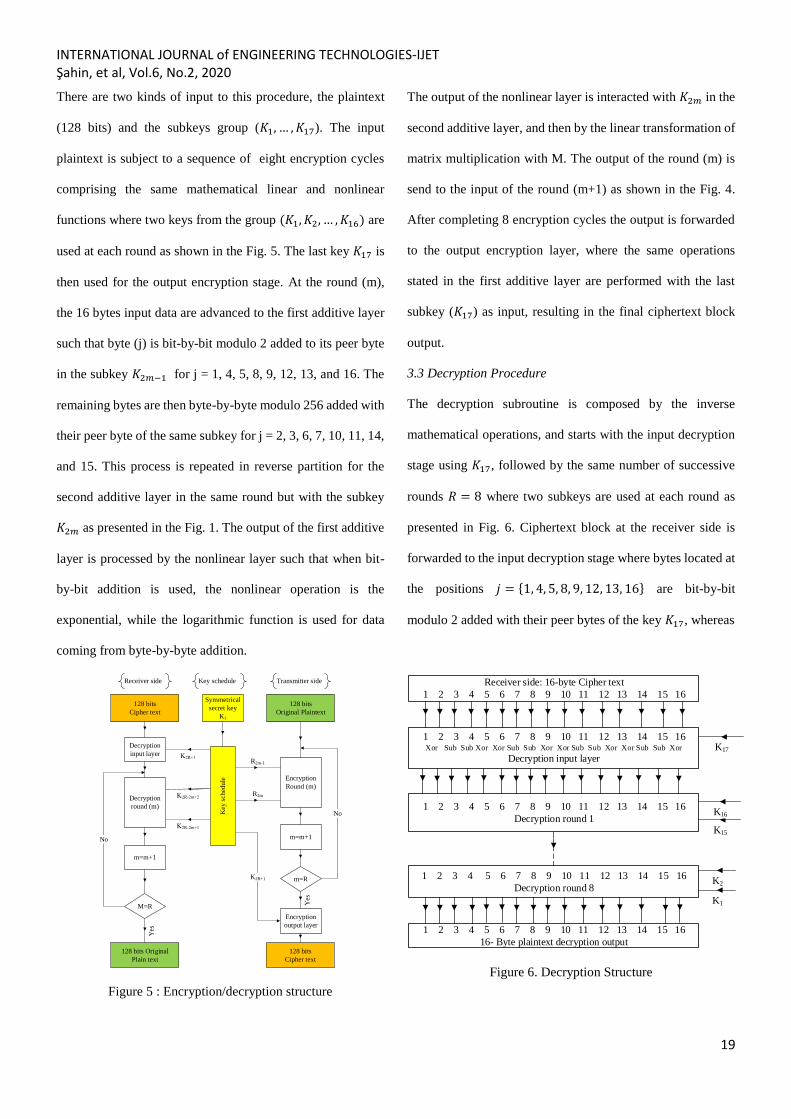
3.2 Encryption Procedure
The general structure of the encryption procedure for 128-bit
key length comprises eight encryption rounds and one
encryption output layer as presented in the Fig. 4.
16-byte Plaintext
1 2 3 4 5 6 7 8 9 10 11 12 13 14 15 16
1 2 3 4 5 6 7 8 9 10 11 12 13 14 15 16
Encryption round 1
1 2 3 4 5 6 7 8 9 10 11 12 13 14 15 16
Encryption round 8
1 2 3 4 5 6 7 8 9 10 11 12 13 14 15 16 Xor Add Add Xor Xor Add Add Xor Xor Add Add Xor Xor Add Add Xor
Encryption output layer
1 2 3 4 5 6 7 8 9 10 11 12 13 14 15 16
Cipher text 16-byte output
K17
K1
K2
K15
K16
Figure 4: Encryption Structure
INTERNATIONAL JOURNAL of ENGINEERING TECHNOLOGIES-IJET Şahin, et al, Vol.6, No.2, 2020
19
There are two kinds of input to this procedure, the plaintext
(128 bits) and the subkeys group (𝐾1, … , 𝐾17). The input
plaintext is subject to a sequence of eight encryption cycles
comprising the same mathematical linear and nonlinear
functions where two keys from the group (𝐾1, 𝐾2, … , 𝐾16) are
used at each round as shown in the Fig. 5. The last key 𝐾17 is
then used for the output encryption stage. At the round (m),
the 16 bytes input data are advanced to the first additive layer
such that byte (j) is bit-by-bit modulo 2 added to its peer byte
in the subkey 𝐾2𝑚−1 for j = 1, 4, 5, 8, 9, 12, 13, and 16. The
remaining bytes are then byte-by-byte modulo 256 added with
their peer byte of the same subkey for j = 2, 3, 6, 7, 10, 11, 14,
and 15. This process is repeated in reverse partition for the
second additive layer in the same round but with the subkey
𝐾2𝑚 as presented in the Fig. 1. The output of the first additive
layer is processed by the nonlinear layer such that when bit-
by-bit addition is used, the nonlinear operation is the
exponential, while the logarithmic function is used for data
coming from byte-by-byte addition.
128 bits
Original Plaintext
Key
sch
edu
le
Encryption
output layer
128 bits
Cipher text
Encryption
Round (m)
m=m+1
Decryption
input layer
Decryption
round (m)
128 bits Original
Plain text
Symmetrical
secret key
K1
M=R
m=R
m=m+1
128 bits
Cipher text
Yes
R2m-1
R2m
Yes
K2R+1
No
No
Transmitter sideReceiver side Key schedule
Figure 5 : Encryption/decryption structure
The output of the nonlinear layer is interacted with 𝐾2𝑚 in the
second additive layer, and then by the linear transformation of
matrix multiplication with M. The output of the round (m) is
send to the input of the round (m+1) as shown in the Fig. 4.
After completing 8 encryption cycles the output is forwarded
to the output encryption layer, where the same operations
stated in the first additive layer are performed with the last
subkey (𝐾17) as input, resulting in the final ciphertext block
output.
3.3 Decryption Procedure
The decryption subroutine is composed by the inverse
mathematical operations, and starts with the input decryption
stage using 𝐾17, followed by the same number of successive
rounds 𝑅 = 8 where two subkeys are used at each round as
presented in Fig. 6. Ciphertext block at the receiver side is
forwarded to the input decryption stage where bytes located at
the positions 𝑗 = {1, 4, 5, 8, 9, 12, 13, 16} are bit-by-bit
modulo 2 added with their peer bytes of the key 𝐾17, whereas
Receiver side: 16-byte Cipher text
1 2 3 4 5 6 7 8 9 10 11 12 13 14 15 16
1 2 3 4 5 6 7 8 9 10 11 12 13 14 15 16 Xor Sub Sub Xor Xor Sub Sub Xor Xor Sub Sub Xor Xor Sub Sub Xor
Decryption input layer
1 2 3 4 5 6 7 8 9 10 11 12 13 14 15 16
Decryption round 1
1 2 3 4 5 6 7 8 9 10 11 12 13 14 15 16
Decryption round 8
1 2 3 4 5 6 7 8 9 10 11 12 13 14 15 16
16- Byte plaintext decryption output
K2
K17
K15
K16
K1
Figure 6. Decryption Structure
INTERNATIONAL JOURNAL of ENGINEERING TECHNOLOGIES-IJET Şahin, et al, Vol.6, No.2, 2020
20
the remainding bytes at the positions 𝑗 = {2, 3, 6, 7, 10, 11, 14,
15} of the subkey are subtracted modulo 256 from their peer
ciphertext bytes. The the data proceeded to the first decryption
cycle where the subkeys 𝐾16 and 𝐾15 are used. The decryption
process is the opposite of encryption, in that, the subkeys
allocation for successif cycles are done in decreasing order
starting from 𝐾16 to 𝐾1. Although the bit-by-bit modulo 2
operation (xor) is still used in the same manner, the byte-by-
byte addition is replaced by the byte-by-byte subtraction. The
decryption round (m) begins by the multipling its 16-byte
input vector by the matrix 𝑀−1 modulo 256. The resulting
vector is then directed to the first additive layer in the
decryption cycle where byte at the positions 𝑗 =
{2, 3, 6, 7, 10, 11, 14, 15} are bit-by-bit modulo 2 added with
their peer bytes of the subkey (𝐾18−2𝑚) while the bytes at the
positions 𝑗 = {1, 4, 5, 8, 9, 12, 13, 16} of the subkey are
subtracted from their peer bytes in the input vector modulo
256, with all their values between 0 and 255. The output of
this layer is directed to the nonlinear layer where the
exponential fuction is applied for byte resulting from xor
operations while a logarithm function is used for byte issued
from subtraction. The result from the decryption cycle (m) is
the output of the second additive layer which is applied with
the reverse operations compared to the first additive layer.
This process is repeated for 8 decryption cycles yielding at the
end to the regeneration of the original plaintext.
4. Simulation Methology and Results
4.1 linear layers implementation
The simulation of SAFER+ is performed by MATLAB portal
where the principle logic functions such as bytes addition, bit
addition, modulo operation, matrix multiplication, bits
rotation, and byte selection exist as in-program functions.
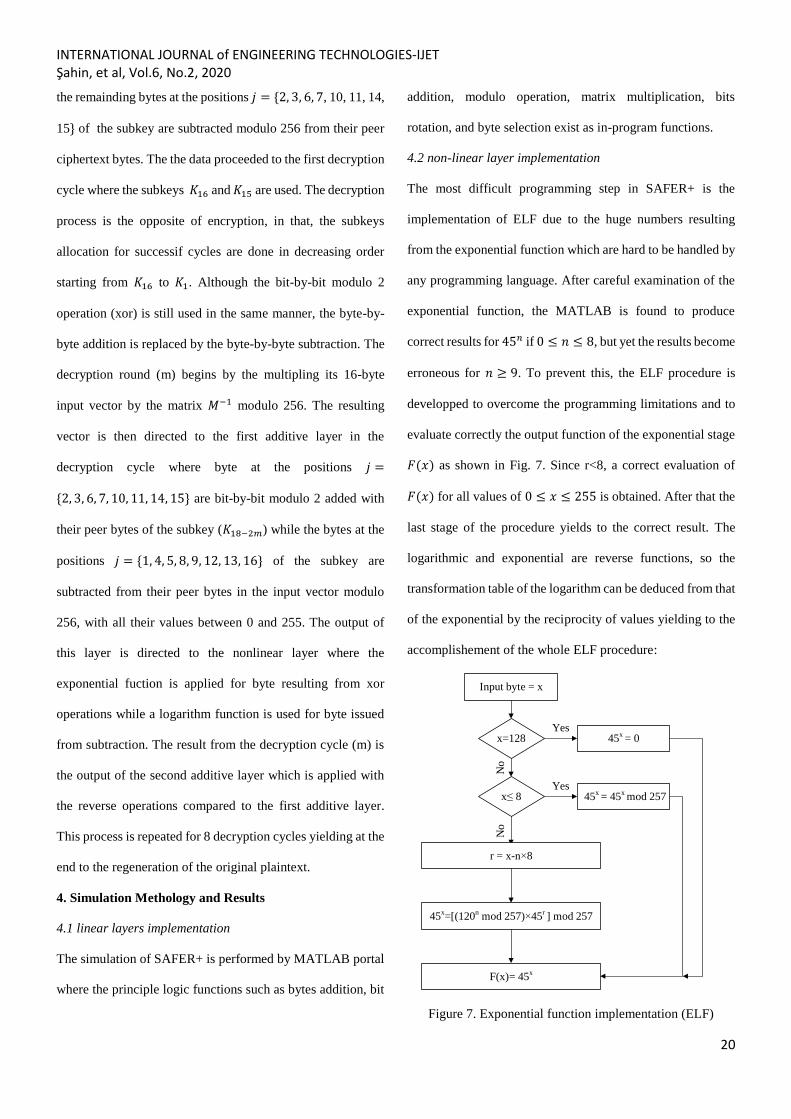
4.2 non-linear layer implementation
The most difficult programming step in SAFER+ is the
implementation of ELF due to the huge numbers resulting
from the exponential function which are hard to be handled by
any programming language. After careful examination of the
exponential function, the MATLAB is found to produce
correct results for 45𝑛 if 0 ≤ 𝑛 ≤ 8, but yet the results become
erroneous for 𝑛 ≥ 9. To prevent this, the ELF procedure is
developped to overcome the programming limitations and to
evaluate correctly the output function of the exponential stage
𝐹(𝑥) as shown in Fig. 7. Since r<8, a correct evaluation of
𝐹(𝑥) for all values of 0 ≤ 𝑥 ≤ 255 is obtained. After that the
last stage of the procedure yields to the correct result. The
logarithmic and exponential are reverse functions, so the
transformation table of the logarithm can be deduced from that
of the exponential by the reciprocity of values yielding to the
accomplishement of the whole ELF procedure:
Input byte = x
x=128
No
No
x 8
r = x-n×8
45x=[(120n mod 257)×45r ] mod 257
F(x)= 45x
45x = 0
45x = 45x mod 257
Yes
Yes
Figure 7. Exponential function implementation (ELF)
INTERNATIONAL JOURNAL of ENGINEERING TECHNOLOGIES-IJET Şahin, et al, Vol.6, No.2, 2020
21
If 𝐹(𝑥) = 45𝑥 = 𝑦, then 𝑙𝑜𝑔45(𝑦) = 𝑥
If 𝑦 = 0, then 𝑙𝑜𝑔45(0) = 128.
The application of the ELF gives the exponential
transformation table for 𝑥 = [0, 1, … ,255], and 𝐹(𝑥) is
evaluated to be:
[1 45 226 147 190 69 21 174 120 3 135
164 184 56 207 63 8 103 9 148 235 38 168
107 189 24 52 27 187 191 114 247 64 53
72 156 81 47 59 85 227 192 159 216 211
243 141 177 255 167 62 220 134 119 215
166 17 251 244 186 146 145 100 131 241
51 239 218 44 181 178 43 136 209 153 203
140 132 29 20 129 151 113 202 95 163 139
87 60 130 196 82 92 28 232 160 4 180 133
74 246 19 84 182 223 12 26 142 222 224
57 252 32 155 36 78 169 152 158 171 242
96 208 108 234 250 199 217 0 212 31 110
67 188 236 83 137 254 122 93 73 201 50
194 249 154 248 109 22 219 89 150 68 233
205 230 70 66 143 10 193 204 185 101 176
210 198 172 30 65 98 41 46 14 116 80 2
90 195 37 123 138 42 91 240 6 13 71 111
112 157 126 16 206 18 39 213 76 79 214
121 48 104 54 117 125 228 237 128 106 144
55 162 94 118 170 197 127 61 175 165 229
25 97 253 77 124 183 11 238 173 75 34
245 231 115 35 33 200 5 225 102 221 179
88 105 99 86 15 161 49 149 23 7 58 40]
where 𝐹(0) = 1, 𝐹(1) = 45,… , 𝐹(255) = 40.
From the above transformation table the logarithmic
tranformation table can be deduced such that if:
𝐹(𝑥) = 45𝑥 = 𝑦, then 𝐺(𝑦) = 𝑙𝑜𝑔45(𝑦) = 𝑥. This gives the
following logarithm transformation table:
[128 0 176 9 96 239 185 253 16 18 159
228 105 186 173 248 192 56 194 101 79 6
148 252 25 222 106 27 93 78 168 130 112
237 232 236 114 179 21 195 255 171 182
71 68 1 172 37 201 250 142 65 26 33 203
211 13 110 254 38 88 218 50 15 32 169
157 132 152 5 156 187 34 140 99 231 197
225 115 198 175 36 91 135 102 39 247 87
244 150 177 183 92 139 213 84 121 223 170
246 62 163 241 17 202 245 209 23 123 147
131 188 189 82 30 235 174 204 214 53 8
200 138 180 226 205 191 217 208 80 89 63
77 98 52 10 72 136 181 86 76 46 107 158
210 61 60 3 19 251 151 81 117 74 145 113
35 190 118 42 95 249 212 85 11 220 55
49 22 116 215 119 167 230 7 219 164 47
70 243 97 69 103 227 12 162 59 28 133
24 4 29 41 160 143 178 90 216 166 126
238 141 83 75 161 154 193 14 122 73 165
44 129 196 199 54 43 127 67 149 51 242
108 104 109 240 2 40 206 221 155 234 94
153 124 20 134 207 229 66 184 64 120 45
58 233 100 31 146 144 125 57 111 224 137
48].
4.3 Data Block Encryption/ decryption
A data block of 16 bytes is used as plaintext to evaluate the
correcteness of the encryption/ decryption SAFER+
implementation. A user key 𝐾1, is given also as input, the
subroutine key schedules is generating using this key the
INTERNATIONAL JOURNAL of ENGINEERING TECHNOLOGIES-IJET Şahin, et al, Vol.6, No.2, 2020
22
group of 17 subkeys (𝐾1, 𝐾2, … , 𝐾17). Based on the input
plaintext and the user key, the ciphertext is the result of the
SAFER+ algorithm as shown in the result table 1. The
decryption process is evaluated through the same key 𝐾1 and
with the collected ciphertext vector as input. The resulting
vector is the same as the plaintext used as input for the
encryption process which validates the exactness of the
software implementation of SAFER+ algorithm and its three
components; the encryption, the decryption, and the key
schdules subroutines. SAFER+ is known by its property as
high speed encryption procedure which enables it to be
choosen for Bluetooth communication among other
applications. The simulation is performed using a personal
computer Intel Core i5 7300HQ, 2.5 GHz, 8 GB DDR4 RAM,
2400 MHz, where the encryption process for one data block
of 16 bytes is done in 0.063131 sec, and the decryption process
in 0.026952 sec. This performs better compared to the
MATLAB implementation of the AES in [8], where at least
0.088 sec is needed for the encryption of 16 bytes by a
computer with similar features. The decryption process in the
presented work consumes less time due to the simplifications
of the logarithmic function evaluation through the ELF
procedure.
Table 1: Simulation results
Input Plaintext 179 166 219 60 135 12 62 153 36 94 13 28 6 183 71 222
Input 𝐾1 41 35 190 132 225 108 214 174 82 144 73 241 241 187 233 235
Output 𝐾2 295 140 213 201 6 109 133 156 73 129 66 88 55 119 11 35
Output 𝐾3 155 204 34 225 28 64 236 49 74 22 144 92 224 214 2 135
Output 𝐾4 147 134 176 54 199 141 87 219 38 162 98 167 109 138 186 230
Output 𝐾5 123 29 255 9 250 122 240 218 65 124 92 57 59 43 149 127
Output 𝐾6 96 204 15 93 122 189 245 243 244 52 219 76 177 210 163 209
Output 𝐾7 56 190 201 32 12 248 157 109 168 81 214 221 102 105 53 81
Output 𝐾8 15 26 46 250 110 124 137 222 74 13 5 12 134 18 149 185
Output 𝐾9 207 61 251 224 179 66 183 96 253 60 37 78 211 15 222 9
Output 𝐾10 68 215 94 56 94 49 35 230 120 133 111 195 97 68 203 173
Output 𝐾11 78 156 190 181 130 222 6 159 38 59 53 238 123 180 138 107
Output 𝐾12 221 238 152 211 241 232 248 255 101 167 37 36 134 238 244 243
Output 𝐾13 55 111 165 66 105 237 214 179 86 233 14 214 53 115 165 201
Output 𝐾14 34 65 73 224 185 205 107 140 123 117 55 254 4 179 82 236
Output 𝐾15 212 162 91 17 41 175 56 251 163 238 13 249 50 54 180 74
Output 𝐾16 51 1 59 215 18 174 202 253 151 91 101 89 167 98 148 104
Output 𝐾17 127 111 186 111 62 132 35 230 184 23 199 252 186 75 227 149
Output ciphertext 224 31 182 10 12 255 84 70 127 13 89 249 9 57 165 220
INTERNATIONAL JOURNAL of ENGINEERING TECHNOLOGIES-IJET Şahin, et al, Vol.6, No.2, 2020
23
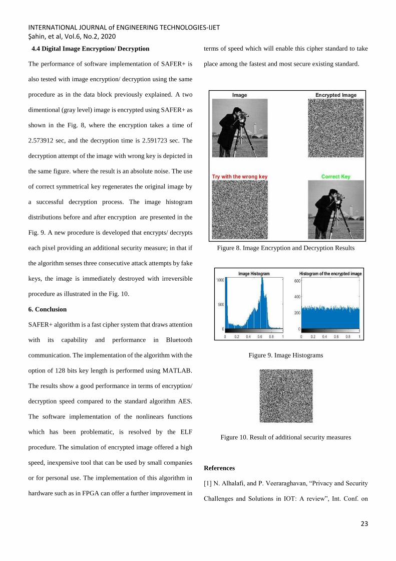
4.4 Digital Image Encryption/ Decryption
The performance of software implementation of SAFER+ is
also tested with image encryption/ decryption using the same
procedure as in the data block previously explained. A two
dimentional (gray level) image is encrypted using SAFER+ as
shown in the Fig. 8, where the encryption takes a time of
2.573912 sec, and the decryption time is 2.591723 sec. The
decryption attempt of the image with wrong key is depicted in
the same figure. where the result is an absolute noise. The use
of correct symmetrical key regenerates the original image by
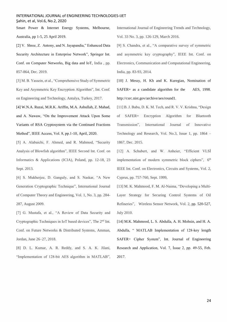
a successful decryption process. The image histogram
distributions before and after encryption are presented in the
Fig. 9. A new procedure is developed that encrypts/ decrypts
each pixel providing an additional security measure; in that if
the algorithm senses three consecutive attack attempts by fake
keys, the image is immediately destroyed with irreversible
procedure as illustrated in the Fig. 10.
6. Conclusion
SAFER+ algorithm is a fast cipher system that draws attention
with its capability and performance in Bluetooth
communication. The implementation of the algorithm with the
option of 128 bits key length is performed using MATLAB.
The results show a good performance in terms of encryption/
decryption speed compared to the standard algorithm AES.
The software implementation of the nonlinears functions
which has been problematic, is resolved by the ELF
procedure. The simulation of encrypted image offered a high
speed, inexpensive tool that can be used by small companies
or for personal use. The implementation of this algorithm in
hardware such as in FPGA can offer a further improvement in
terms of speed which will enable this cipher standard to take
place among the fastest and most secure existing standard.
Figure 8. Image Encryption and Decryption Results
Figure 9. Image Histograms
Figure 10. Result of additional security measures
References
[1] N. Alhalafi, and P. Veeraraghavan, “Privacy and Security
Challenges and Solutions in IOT: A review”, Int. Conf. on
INTERNATIONAL JOURNAL of ENGINEERING TECHNOLOGIES-IJET Şahin, et al, Vol.6, No.2, 2020
24
Smart Power & Internet Energy Systems, Melbourne,
Australia, pp 1-5, 25 April 2019.
[2] V. Shree, Z. Antony, and N. Jayapandia,” Enhanced Data
Security Architecture in Enterprise Network”, Springer Int.
Conf. on Computer Networks, Big data and IoT, India , pp.
857-864, Dec. 2019.
[3] M. B. Yassein, et al., “Comprehensive Study of Symmetric
Key and Asymmetric Key Encryption Algorithm”, Int. Conf.
on Engineering and Technology, Antalya, Turkey, 2017.
[4] W.N.A. Ruzai, M.R.K. Ariffin, M.A. Asbullah, Z. Mahad,
and A. Nawaw, “On the Improvement Attack Upon Some
Variants of RSA Cryptosystem via the Continued Fractions
Method”, IEEE Access, Vol. 8, pp.1-10, April, 2020.
[5] A. Alabaichi, F. Ahmed, and R. Mahmod, “Security
Analysis of Blowfish algorithm”, IEEE Second Int. Conf. on
Informatics & Applications (ICIA), Poland, pp. 12-18, 23
Sept. 2013.
[6] S. Mukherjee, D. Ganguly, and S. Naskar, “A New
Generation Cryptographic Technique”, International Journal
of Computer Theory and Engineering, Vol. 1, No. 3, pp. 284-
287, August 2009.
[7] G. Mustafa, et al., “A Review of Data Security and
Cryptographic Techniques in IoT based devices”, The 2nd Int.
Conf. on Future Networks & Distributed Systems, Amman,
Jordan, June 26–27, 2018.
[8] D. L. Kumar, A. R. Reddy, and S. A. K. Jilani,
“Implementation of 128-bit AES algorithm in MATLAB”,
International Journal of Engineering Trends and Technology,
Vol. 33 No. 3, pp. 126-129, March 2016.
[9] S. Chandra, et al., “A comparative survey of symmetric
and asymmetric key cryptography”, IEEE Int. Conf. on
Electronics, Communication and Computational Engineering,
India, pp. 83-93, 2014.
[10] J. Messy, H. Kh and K. Kuregian, Nomination of
SAFER+ as a candidate algorithm for the AES, 1998.
http://csrc.nist.gov/archive/aes/round1.
[11] B. J. Babu, D. K. M. Tech, and R. V. V. Krishna, “Design
of SAFER+ Encryption Algorithm for Bluetooth
Transmission”, International Journal of Innovative
Technology and Research, Vol. No.3, Issue 1, pp. 1864 –
1867, Dec. 2015.
[12] A. Schubert, and W. Anheier, “Efficient VLSİ
implementation of modern symmetric block ciphers”, 6th
IEEE Int. Conf. on Electronics, Circuits and Systems, Vol. 2,
Cyprus, pp. 757-760, Sept. 1999,
[13] M. K. Mahmood, F. M. Al-Naima, “Developing a Multi-
Layer Strategy for Securing Control Systems of Oil
Refineries”, Wireless Sensor Network, Vol. 2, pp. 520-527,
July 2010.
[14] M.K. Mahmood, L. S. Abdulla, A. H. Mohsin, and H. A.
Abdulla, “ MATLAB Implementation of 128-key length
SAFER+ Cipher System”, Int. Journal of Engineering
Research and Application, Vol. 7, İssue 2, pp. 49-55, Feb.
2017.