Embed Size (px)
Citation preview
DRI-AIR INDUSTRIES, INC.
OPERATING MANUAL - AHM/HPHM 2-4 HOPPER MOUNT DRYERSRevision 10/8/02
Page 1
AHM & HPHM 2-4HOPPER MOUNT DRYERS
OPERATING MANUAL
DRI-AIR INDUSTRIES, INC.
OPERATING MANUAL - AHM/HPHM2-4 HOPPER MOUNT DRYERSRevision 10/8/02
Page 2
DRI-AIR INDUSTRIES, INC.
16 THOMPSON ROADP.O. BOX 1020EAST WINDSOR, CT 06088-1020
Tel. (860) 627-5110FAX (860) 623-4477Internet http://www.dri-air.come-mail: [email protected]
DRI-AIR INDUSTRIES, INC.
OPERATING MANUAL - AHM/HPHM 2-4 HOPPER MOUNT DRYERSRevision 10/8/02
Page 3
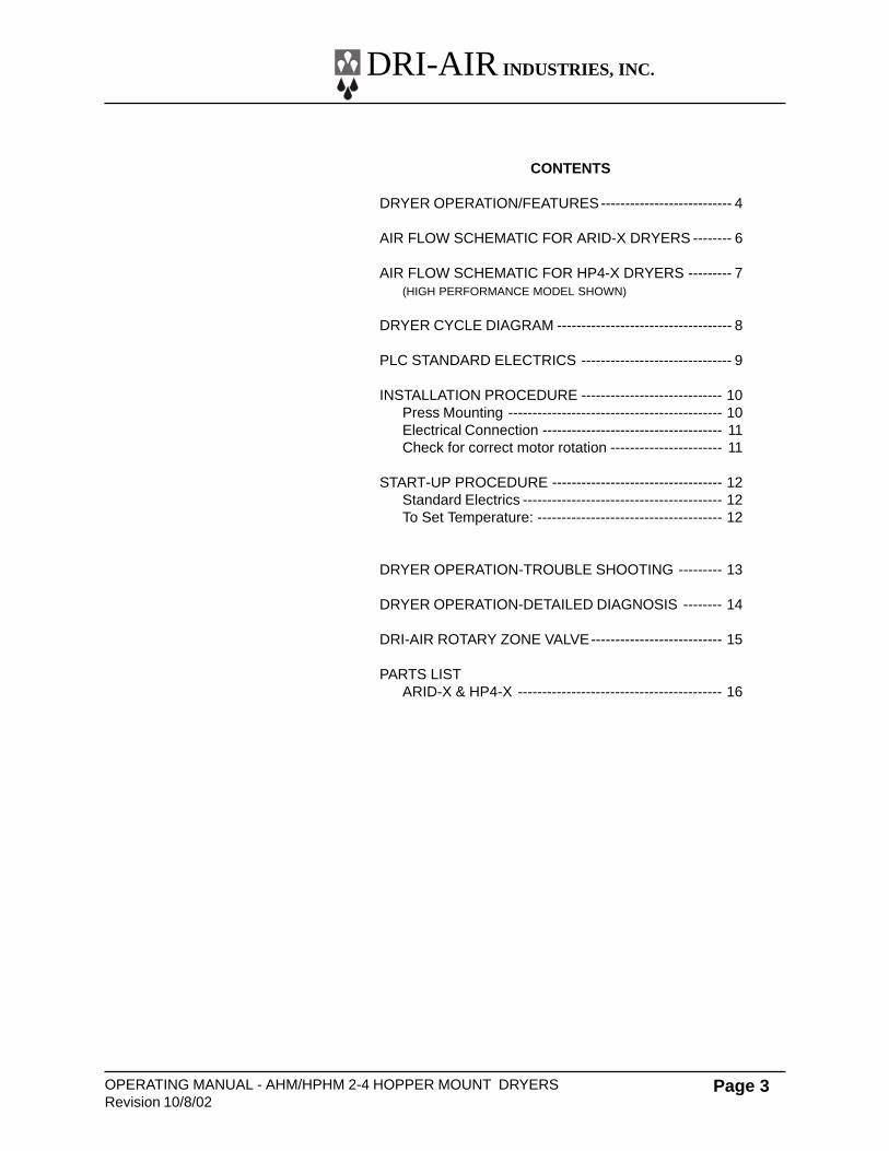
CONTENTS
DRYER OPERATION/FEATURES--------------------------- 4
AIR FLOW SCHEMATIC FOR ARID-X DRYERS -------- 6
AIR FLOW SCHEMATIC FOR HP4-X DRYERS --------- 7(HIGH PERFORMANCE MODEL SHOWN)
DRYER CYCLE DIAGRAM ------------------------------------ 8
PLC STANDARD ELECTRICS ------------------------------- 9
INSTALLATION PROCEDURE ----------------------------- 10Press Mounting -------------------------------------------- 10Electrical Connection ------------------------------------- 11Check for correct motor rotation ----------------------- 11
START-UP PROCEDURE ----------------------------------- 12Standard Electrics ----------------------------------------- 12To Set Temperature: -------------------------------------- 12
DRYER OPERATION-TROUBLE SHOOTING --------- 13
DRYER OPERATION-DETAILED DIAGNOSIS -------- 14
DRI-AIR ROTARY ZONE VALVE--------------------------- 15
PARTS LISTARID-X & HP4-X ------------------------------------------ 16
DRI-AIR INDUSTRIES, INC.
OPERATING MANUAL - AHM/HPHM2-4 HOPPER MOUNT DRYERSRevision 10/8/02
Page 4
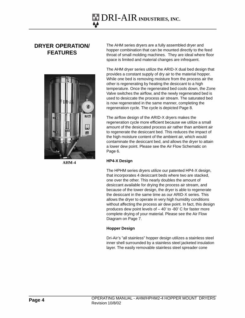
The AHM series dryers are a fully assembled dryer andhopper combination that can be mounted directly to the feedthroat of small molding machines. They are ideal where floorspace is limited and material changes are infrequent.
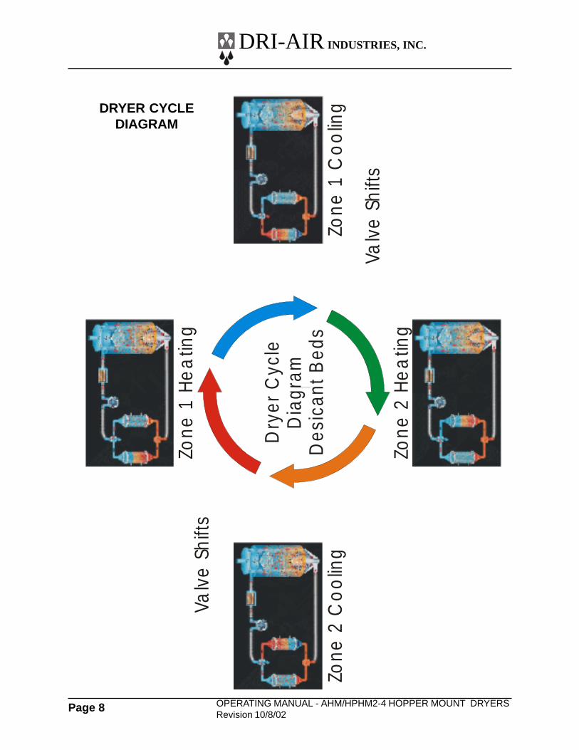
The AHM dryer series utilize the ARID-X dual bed design thatprovides a constant supply of dry air to the material hopper.While one bed is removing moisture from the process air theother is regenerating by heating the desiccant to a hightemperature. Once the regenerated bed cools down, the ZoneValve switches the airflow, and the newly regenerated bed isused to desiccate the process air stream. The saturated bedis now regenerated in the same manner, completing theregeneration cycle. The cycle is depicted Page 8.
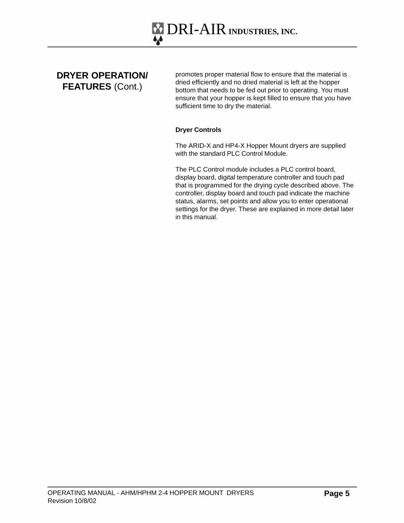
The airflow design of the ARID-X dryers makes theregeneration cycle more efficient because we utilize a smallamount of the desiccated process air rather than ambient airto regenerate the desiccant bed. This reduces the impact ofthe high moisture content of the ambient air, which wouldcontaminate the desiccant bed, and allows the dryer to attaina lower dew point. Please see the Air Flow Schematic onPage 6.
HP4-X Design
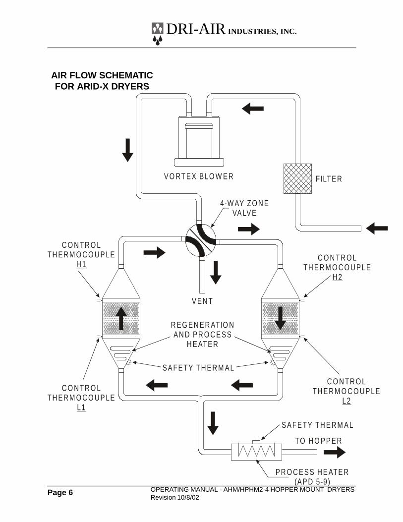
The HPHM series dryers utilize our patented HP4-X design,that incorporates 4 desiccant beds where two are stacked,one over the other. This nearly doubles the amount ofdesiccant available for drying the process air stream, andbecause of the tower design, the dryer is able to regeneratethe desiccant in the same time as our ARID-X series. Thisallows the dryer to operate in very high humidity conditionswithout affecting the process air dew point. In fact, this designproduces dew point levels of – 40’ to -80’ C for faster morecomplete drying of your material. Please see the Air FlowDiagram on Page 7.
Hopper Design
Dri-Air’s ”all stainless” hopper design utilizes a stainless steelinner shell surrounded by a stainless steel jacketed insulationlayer. The easily removable stainless steel spreader cone
DRYER OPERATION/FEATURES
AHM-4
DRI-AIR INDUSTRIES, INC.
OPERATING MANUAL - AHM/HPHM 2-4 HOPPER MOUNT DRYERSRevision 10/8/02
Page 5
promotes proper material flow to ensure that the material isdried efficiently and no dried material is left at the hopperbottom that needs to be fed out prior to operating. You mustensure that your hopper is kept filled to ensure that you havesufficient time to dry the material.
Dryer Controls
The ARID-X and HP4-X Hopper Mount dryers are suppliedwith the standard PLC Control Module.
The PLC Control module includes a PLC control board,display board, digital temperature controller and touch padthat is programmed for the drying cycle described above. Thecontroller, display board and touch pad indicate the machinestatus, alarms, set points and allow you to enter operationalsettings for the dryer. These are explained in more detail laterin this manual.
DRYER OPERATION/FEATURES (Cont.)
DRI-AIR INDUSTRIES, INC.
OPERATING MANUAL - AHM/HPHM2-4 HOPPER MOUNT DRYERSRevision 10/8/02
Page 6
AIR FLOW SCHEMATICFOR ARID-X DRYERS
XX
V O RTE X B LO W E R
4-W AY ZO N EVA LV E
FILTE R
V E N T
S A F E TY TH E R M A L
S A F E TY TH E R M A L
R E G E N E R ATIO NA N D P R O C E S S
H E ATE R
TO H O P P E R
P R O C E S S H E ATE R(A P D 5-9)
C O N TR O LTH E R M O C O U P LE
H 2
C O N TR O LTH E R M O C O U P LE
L1
C O N TR O LTH E R M O C O U P LE
L2
C O N TR O LTH E R M O C O U P LE
H 1
DRI-AIR INDUSTRIES, INC.
OPERATING MANUAL - AHM/HPHM 2-4 HOPPER MOUNT DRYERSRevision 10/8/02
Page 7
AIR FLOW SCHEMATICFOR HP4-X DRYERS
XX
V O RTE X B LO W ER
4-W AY ZO N EVA LV E
FILTE R
V E N T
C O N TR O LTH E R M O C O U P LE *
M 2
C O N TR O L TH E R M O C O U P LE *
M 1
S A FE TY TH E R M AL
S A FE TY TH E R M AL
S A FE TY TH E R M AL
R E G E N E R ATIO NA N D P R O C E SS
H E ATE R
R E G E N E R ATIO NA N D P R O C E SS
H E ATE R
TO H O P P E R
P R O C E S S H E ATE R(H P D 5-9 )
S E C O N D A RYR E G E N E R ATIO N
H E ATE R
C O N TR O L TH E R M O C O U P LE
H 1
C O N TR O LTH E R M O C O U P LE
H 2
C O N TR O LTH E R M O C O U P LE
L2
C O N TR O L TH E R M O C O U P LE
L1
* - C O N TR O L TH E R M O C O U P LEFO R P LC C O N TR O L O N LY
DRI-AIR INDUSTRIES, INC.
OPERATING MANUAL - AHM/HPHM2-4 HOPPER MOUNT DRYERSRevision 10/8/02
Page 8
Dry
er C
ycle
Dia
gram
Des
ican
t Bed
s
Zone
1 H
ea
ting
Zone
2 C
oo
ling
Zone
2 H
ea
ting
Zone
1 C
oo
ling
Valv
e S
hifts
Valv
e S
hifts
DRYER CYCLEDIAGRAM
XX
DRI-AIR INDUSTRIES, INC.
OPERATING MANUAL - AHM/HPHM 2-4 HOPPER MOUNT DRYERSRevision 10/8/02
Page 9
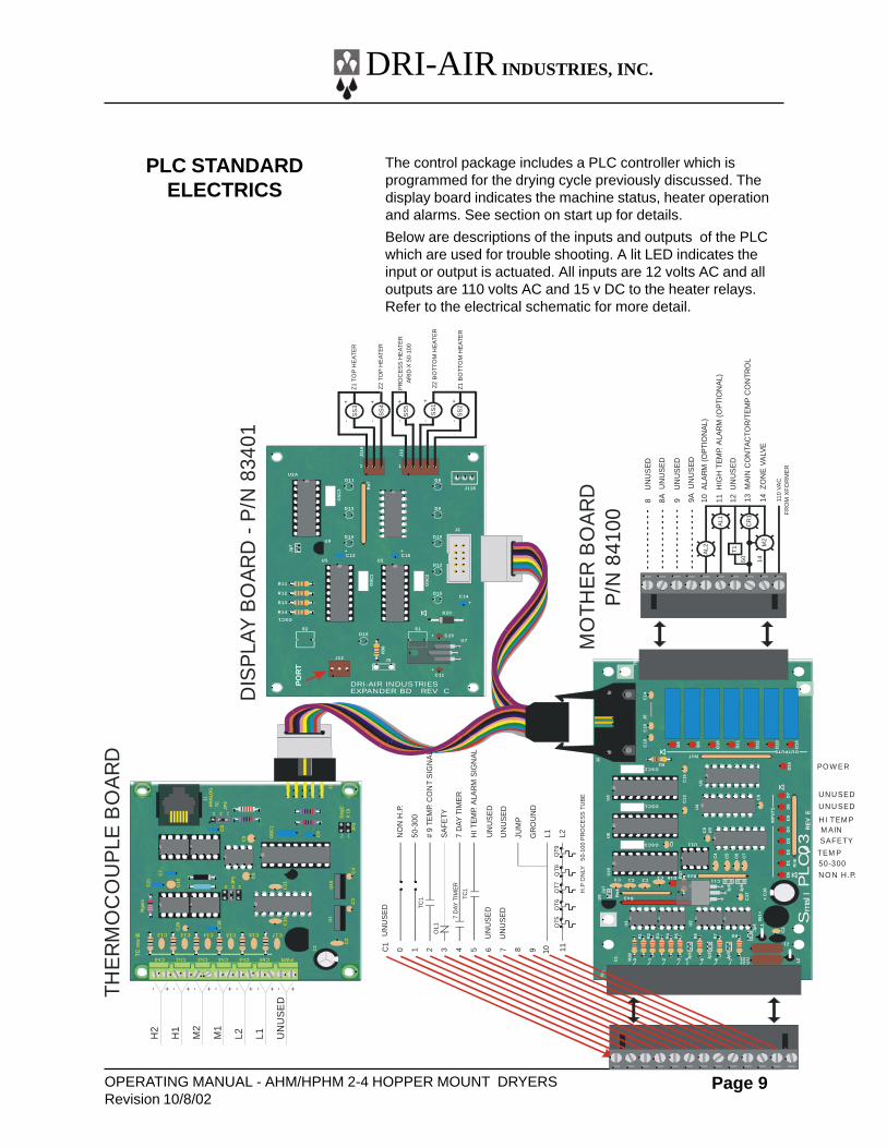
The control package includes a PLC controller which isprogrammed for the drying cycle previously discussed. Thedisplay board indicates the machine status, heater operationand alarms. See section on start up for details.
Below are descriptions of the inputs and outputs of the PLCwhich are used for trouble shooting. A lit LED indicates theinput or output is actuated. All inputs are 12 volts AC and alloutputs are 110 volts AC and 15 v DC to the heater relays.Refer to the electrical schematic for more detail.
PLC STANDARDELECTRICS
XX
S2
J12
D16
C 11
C 20
C 14
C 15C 13
D20
D15
D12
D10D14
D9D13
D8D11
J5
Jp
7
J2
1 1
J118
J11
J11A
U7
U5
U9
U2
U2A
S1
R36
OS
C1
OS
C3
OS
C2
Rn
7
OSC1
R11
R12
R13
R14
+
++
++
C18
C1
3
C16
D16
C12
Rn5
Rn
6
INP
UT
S
Rn7OUTPUTS
R37
R38
Tb
1
R1
R2
R3
R4
R5
R6
Jp1
Jp2
Jp3
Jp4
Jp6
Jp5
Br1
++
C18
C17
C22C23
L1
L2
Z1
C2
R7 R8
C11C0 C1 C2C3
C2
U3
U4
U6
C8
U11
C15
D8
D9
D0
D1
D2
D3
D4
D5
D6
D7
D10
D1
1
D12
D13
D14
D15
C4
C5
C6
C7
C9
C19
J5
R2
OSC1
OSC3
OSC2
J2
U8
U9
U1
C1 0 1 2 3 5 6 74
U2
Jp7
Rn
4
Rn3
U5
U18
C1
4
Tb
2
Sm
all
PLC
03
RE
VE
8U
NU
SE
D
8AU
NU
SE
D
9U
NU
SE
D
9AU
NU
SE
D
10A
LAR
M(O
PTI
ON
AL)
11H
IGH
TEM
P.A
LAR
M(O
PTI
ON
AL)
12U
NU
SE
D
13M
AIN
CO
NTA
CTO
R/T
EM
PC
ON
TRO
L
14Z
ON
EVA
LVE
PR
OC
ES
SH
EA
TER
AR
ID-X
50-1
00
Z1
TOP
HE
ATE
R
Z2
TOP
HE
ATE
R
TEM P
SAFETYM AIN
HI TEM P
PO W ER
DIS
PLA
YB
OA
RD
-P
/N83
401
THE
RM
OC
OU
PLE
BO
AR
D
MO
THE
RB
OA
RD
PO
RT
DRI-AIR INDUSTRIESEXPANDER BD REV C
SS
4
AL2
CR
1
M2
AL1
SS
1
SS
2
110
VA
CF
RO
MX
FO
RM
ER
T1
50 14
UN
US
ED
NO
NH
.P.
50-3
00
#9
TEM
P.C
ON
TS
IGN
AL
SA
FETY
7D
AYTI
ME
R
HIT
EM
P.A
LAR
MS
IGN
AL
UN
US
ED
UN
US
ED
UN
US
ED
GR
OU
ND
L1 L2Q
T9Q
T8Q
T7Q
T6Q
T5
OL1
7D
AYTI
ME
R
H.P
ON
LY50
-100
PR
OC
ES
STU
BE
C1
0 1 2 3 4 5 6 7
C13 C14 C15 C16 C17
Ch5Ch4Ch3Ch2 PWRCh1Ch0
C3
C4
U1
U10
C2
C21
TC
rev
BR
gain
C20
C19
C18
C9
J2
JP2
JP3
Deg
CX
10
OS
C1
JP1
AN
ALO
GTC
C8
J1
C7
C6
C1
C10
C11
C5
1
1
1
2
2
2
3
3
C12
- + - + - + - + - + - + - +
H2
H1
M2
M1
L2 L1 UN
US
ED
SS
3
SS
5
-
+-
+-
+++
--
Z1
BO
TTO
M H
EA
TER
Z2 B
OT
TOM
HE
AT
ER
UNUSED
UNUSED
50-300
NO N H .P.
TC1
TC1
JUM
P
UN
US
ED
8 9 10 11
P/N
841
00
DRI-AIR INDUSTRIES, INC.
OPERATING MANUAL - AHM/HPHM2-4 HOPPER MOUNT DRYERSRevision 10/8/02
Page 10
Press Mounting
Each AHM series dryer hopper is supplied with a 6 x 6 inchmounting flange with a slide gate. The flange is configuredwith two rectangular 3.25 x 5 inch bolt hole patterns, rotated90° from each other to allow for the dryer to be oriented inany quadrant.
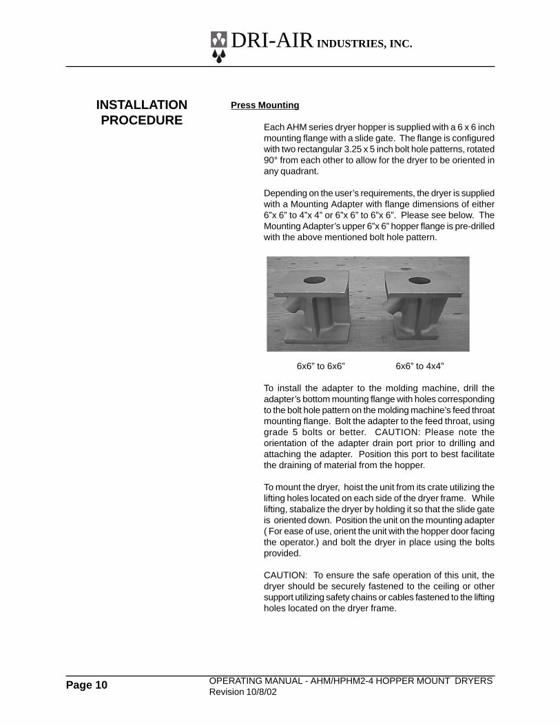
Depending on the user’s requirements, the dryer is suppliedwith a Mounting Adapter with flange dimensions of either6”x 6” to 4”x 4” or 6”x 6” to 6”x 6”. Please see below. TheMounting Adapter’s upper 6”x 6” hopper flange is pre-drilledwith the above mentioned bolt hole pattern.
6x6” to 6x6” 6x6” to 4x4”
To install the adapter to the molding machine, drill theadapter’s bottom mounting flange with holes correspondingto the bolt hole pattern on the molding machine’s feed throatmounting flange. Bolt the adapter to the feed throat, usinggrade 5 bolts or better. CAUTION: Please note theorientation of the adapter drain port prior to drilling andattaching the adapter. Position this port to best facilitatethe draining of material from the hopper.
To mount the dryer, hoist the unit from its crate utilizing thelifting holes located on each side of the dryer frame. Whilelifting, stabalize the dryer by holding it so that the slide gateis oriented down. Position the unit on the mounting adapter( For ease of use, orient the unit with the hopper door facingthe operator.) and bolt the dryer in place using the boltsprovided.
CAUTION: To ensure the safe operation of this unit, thedryer should be securely fastened to the ceiling or othersupport utilizing safety chains or cables fastened to the liftingholes located on the dryer frame.
INSTALLATIONPROCEDURE
DRI-AIR INDUSTRIES, INC.
OPERATING MANUAL - AHM/HPHM 2-4 HOPPER MOUNT DRYERSRevision 10/8/02
Page 11
Electrical Connection:
Open electrical panel enclosure by turning the disconnect offand removing the four enclosure cover allen-head screws sothat the enclosure cover can be removed. Locate thedisconnect by following the operating handle down to theelectrical panel.
Insert the incoming power cable or conduit through the holeprovided on the top side of the enclosure.
« use approved wire and fastening means «
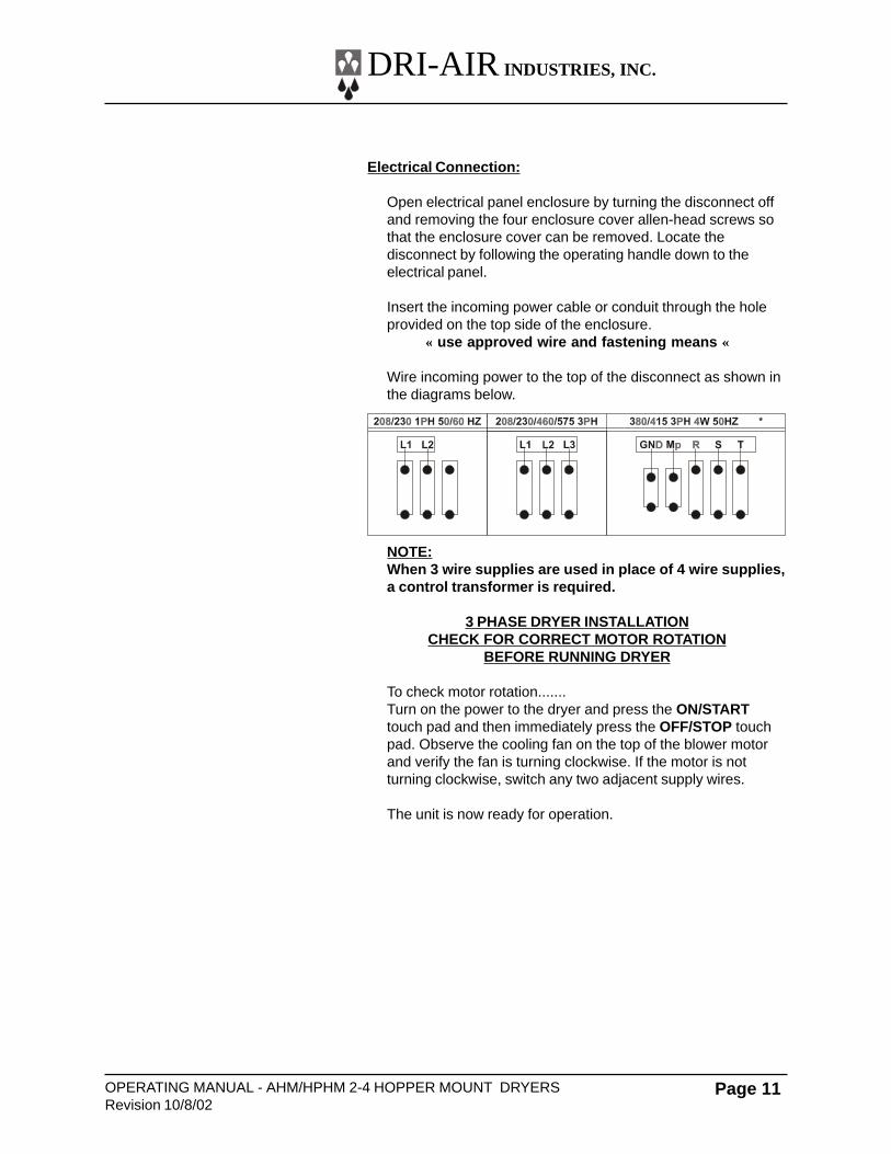
Wire incoming power to the top of the disconnect as shown inthe diagrams below.
NOTE:When 3 wire supplies are used in place of 4 wire supplies,a control transformer is required.
3 PHASE DRYER INSTALLATIONCHECK FOR CORRECT MOTOR ROTATION
BEFORE RUNNING DRYER
To check motor rotation.......Turn on the power to the dryer and press the ON/STARTtouch pad and then immediately press the OFF/STOP touchpad. Observe the cooling fan on the top of the blower motorand verify the fan is turning clockwise. If the motor is notturning clockwise, switch any two adjacent supply wires.
The unit is now ready for operation.
DRI-AIR INDUSTRIES, INC.
OPERATING MANUAL - AHM/HPHM2-4 HOPPER MOUNT DRYERSRevision 10/8/02
Page 12
Standard Electrics
Operating this unit is very simple. Once the dryer isconnected to the facility power supply, the unit can be startedby turning the disconnect located on the electrical panelenclosure to the ON position and pressing the ON button onthe Control Panel Key Pad. To shut the dryer off, simply pushthe OFF button on the Control Panel Key Pad and turn thedisconnect to the OFF position.
Setting the process air temperature is done using the DigitalController.
For a more detailed explanation, see the following sections.
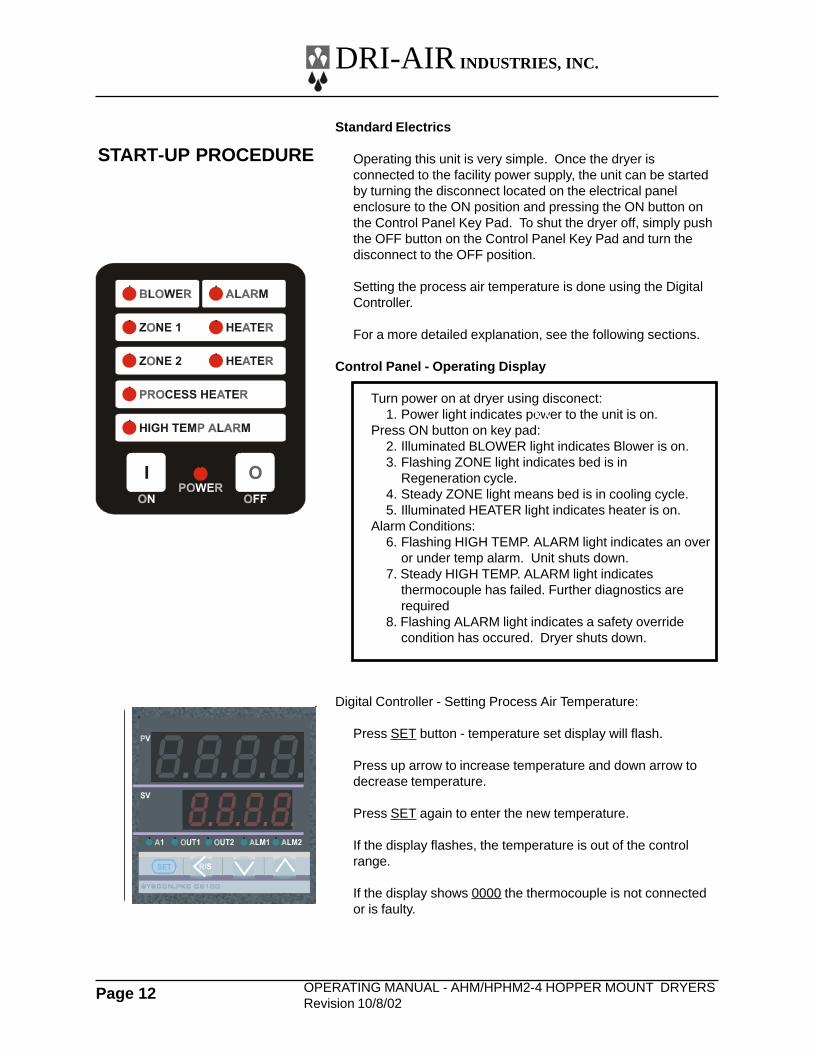
Control Panel - Operating Display
Turn power on at dryer using disconect:1. Power light indicates power to the unit is on.
Press ON button on key pad:2. Illuminated BLOWER light indicates Blower is on.3. Flashing ZONE light indicates bed is in
Regeneration cycle.4. Steady ZONE light means bed is in cooling cycle.5. Illuminated HEATER light indicates heater is on.
Alarm Conditions:6. Flashing HIGH TEMP. ALARM light indicates an over
or under temp alarm. Unit shuts down.7. Steady HIGH TEMP. ALARM light indicates
thermocouple has failed. Further diagnostics arerequired
8. Flashing ALARM light indicates a safety overridecondition has occured. Dryer shuts down.
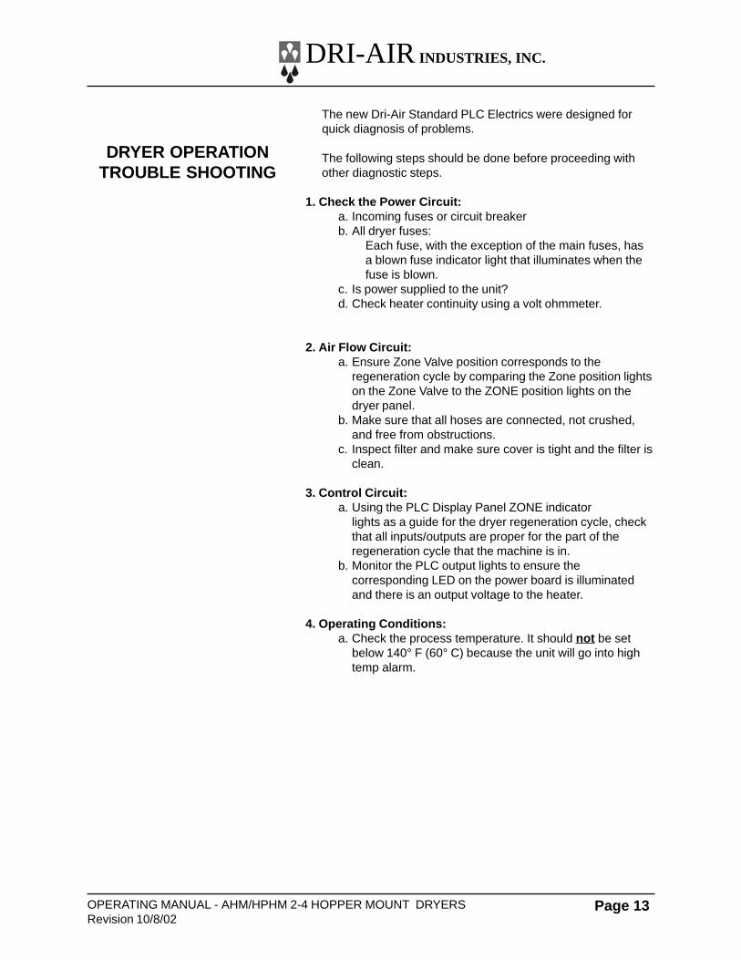
Digital Controller - Setting Process Air Temperature:
Press SET button - temperature set display will flash.
Press up arrow to increase temperature and down arrow todecrease temperature.
Press SET again to enter the new temperature.
If the display flashes, the temperature is out of the controlrange.
If the display shows 0000 the thermocouple is not connectedor is faulty.
START-UP PROCEDURE
XX
DRI-AIR INDUSTRIES, INC.
OPERATING MANUAL - AHM/HPHM 2-4 HOPPER MOUNT DRYERSRevision 10/8/02
Page 13
The new Dri-Air Standard PLC Electrics were designed forquick diagnosis of problems.
The following steps should be done before proceeding withother diagnostic steps.
1. Check the Power Circuit:a. Incoming fuses or circuit breakerb. All dryer fuses:
Each fuse, with the exception of the main fuses, hasa blown fuse indicator light that illuminates when thefuse is blown.
c. Is power supplied to the unit?d. Check heater continuity using a volt ohmmeter.
2. Air Flow Circuit:a. Ensure Zone Valve position corresponds to the
regeneration cycle by comparing the Zone position lightson the Zone Valve to the ZONE position lights on thedryer panel.
b. Make sure that all hoses are connected, not crushed,and free from obstructions.
c. Inspect filter and make sure cover is tight and the filter isclean.
3. Control Circuit:a. Using the PLC Display Panel ZONE indicator
lights as a guide for the dryer regeneration cycle, checkthat all inputs/outputs are proper for the part of theregeneration cycle that the machine is in.
b. Monitor the PLC output lights to ensure thecorresponding LED on the power board is illuminatedand there is an output voltage to the heater.
4. Operating Conditions:a. Check the process temperature. It should not be set
below 140° F (60° C) because the unit will go into hightemp alarm.
DRYER OPERATIONTROUBLE SHOOTING
DRI-AIR INDUSTRIES, INC.
OPERATING MANUAL - AHM/HPHM2-4 HOPPER MOUNT DRYERSRevision 10/8/02
Page 14
Machine will not start: Power light is not on.
1. Check circuit breakers (CB1) or incoming fuses insidecontrol box to see if they are tripped or blown. Resetcircuit breakers by turning them off and then on.
2. Check small fuses (FU1 & FU2) next to contactor. TheLED will be lit if they are blown. Replace if necessary byopening the fuse holder and put new fuse into holder.
3. Check that incoming power to the unit is proper.4. Check safety snap discs.
Alarm light is flashing: Unit will not run.Main contactor is not pulling in.
1. Check the motor overload OL1 located in the panel. If itis tripped, the window will show as orange/yellow. Resetoverload by pushing in the reset button.
Machine will not run: High Temp Alarm Light flashing:
This indicates that the temperature has exceeded the highlimit programmed into the temperature control or the settemperature can not be reached.
Press stop and restart machine holding in the start button.Monitor the actual temperature to see if it exceeds the setpoint or can not reach the set point. If it can not reach setpoint, see section below.
Machine will not run. High Temperature Alarm on, notflashing:
1. This indicates an “open” thermocouple or thetemperature in the desiccant tower exceeded 900° F.
Machine will not reach temperature:
1. If the process heater light is not lit.A. Check output from temperature controller and input to
PLC.B. Check the thermocouple. The tip should be in the
middle of the hose.
2. If the process heater light is lit.A. Check fuses on power boardB. Check solid state relays on power board.C.Check that the air flow is correct.D.Check blower rotationE. Check heater for continuity.
DRYER OPERATIONDETAILED DIAGNOSIS(PLC Controlled Dryer)
DRI-AIR INDUSTRIES, INC.
OPERATING MANUAL - AHM/HPHM 2-4 HOPPER MOUNT DRYERSRevision 10/8/02
Page 15
Check the limit first by pressing the SET button on thetemperature control and holding until AL is displayed. Thesetting shown indicated the amount over set point that thealarm will be actuated. It is factory set to 50°F (30°C) andshould not be set below 30°F (16°C) or it will actuate too soon.
If the temp exceeds the set point check the following:
1. Remove the hose from the top of the hopper to check airflow. There should be air flow out of the hopper with asuction on the hose. If there is little or no flow, check theinlet hose.
2. Inspect the filter to make sure that it is clean and notaffecting the air flow.
3. Check the power boards to see if one of the solid staterelays has failed on. Using an ammeter or voltmeter onthe output to the heater, see if there is power when theLED is not lit which will indicate a failed relay.
4. Check the valve position.
The Dri-Air rotary valve is designed to provide very little flowrestriction and no leakage. It incorporates high temperature,self adjusting seals for years of trouble free service. Theelectrical controls are built into the end of the valve andinclude position lights.
Trouble shooting is easy. If the lights indicating position do notmatch the zone displayed on the control panel, or there are nolights, the valve is not working properly. See if the cam isactuating a switch.
DO NOT PUT FINGERS INTO VALVE WITH POWER ON
Check all electrical connections to make sure they are tight.
Contact factory with the serial number of the dryer for areplacement valve.
DRI-AIRROTARY ZONE VALVE
DRI-AIR INDUSTRIES, INC.
OPERATING MANUAL - AHM/HPHM2-4 HOPPER MOUNT DRYERSRevision 10/8/02
Page 16
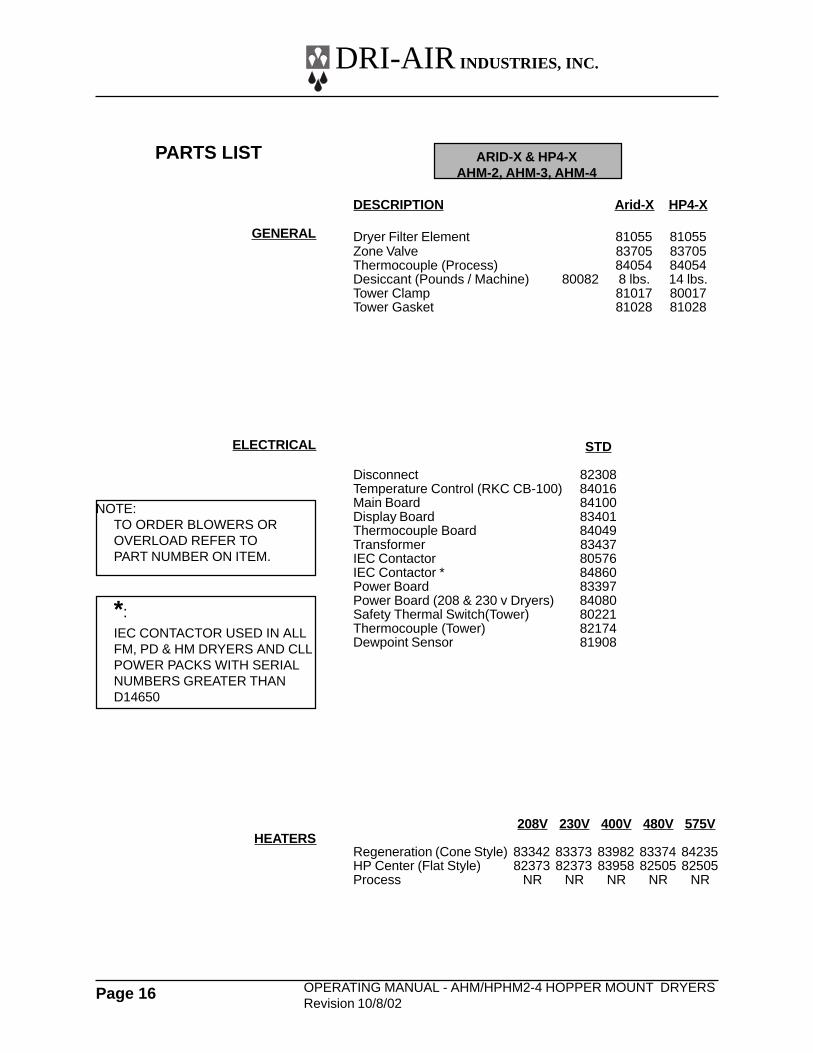
PARTS LIST
GENERAL
ARID-X & HP4-XAHM-2, AHM-3, AHM-4
DESCRIPTION Arid-X HP4-X
Dryer Filter Element 81055 81055Zone Valve 83705 83705Thermocouple (Process) 84054 84054Desiccant (Pounds / Machine) 80082 8 lbs. 14 lbs.Tower Clamp 81017 80017Tower Gasket 81028 81028
STD
Disconnect 82308Temperature Control (RKC CB-100) 84016Main Board 84100Display Board 83401Thermocouple Board 84049Transformer 83437IEC Contactor 80576IEC Contactor * 84860Power Board 83397Power Board (208 & 230 v Dryers) 84080Safety Thermal Switch(Tower) 80221Thermocouple (Tower) 82174Dewpoint Sensor 81908
208V 230V 400V 480V 575V
Regeneration (Cone Style) 83342 83373 83982 83374 84235HP Center (Flat Style) 82373 82373 83958 82505 82505Process NR NR NR NR NR
ELECTRICAL
HEATERS
NOTE:TO ORDER BLOWERS OROVERLOAD REFER TOPART NUMBER ON ITEM.
*:IEC CONTACTOR USED IN ALLFM, PD & HM DRYERS AND CLLPOWER PACKS WITH SERIALNUMBERS GREATER THAND14650
DRI-AIR INDUSTRIES, INC.
OPERATING MANUAL - AHM/HPHM 2-4 HOPPER MOUNT DRYERSRevision 10/8/02
Page 17
NOTES:
DRI-AIR INDUSTRIES, INC.
OPERATING MANUAL - AHM/HPHM2-4 HOPPER MOUNT DRYERSRevision 10/8/02
Page 18
NOTES:

DRI-AIR INDUSTRIES, INC.
OPERATING MANUAL - AHM/HPHM 2-4 HOPPER MOUNT DRYERSRevision 10/8/02
Page 19
NOTES: