Embed Size (px)
Citation preview
2007 Standard for
Reverberation Room Qualification and Testing Procedures for Determining Sound Power of HVAC
Equipment
AHRI Standard 220 (Formerly ARI Standard 220)
Price $10.00 (M) $20.00 (NM) ©Copyright 2007, by Air-Conditioning, Heating, and Refrigeration Institute
Printed in U.S.A. Registered United States Patent and Trademark Office
IMPORTANT
SAFETY DISCLAIMER
AHRI does not set safety standards and does not certify or guarantee the safety of any products, components or
systems designed, tested, rated, installed or operated in accordance with this standard/guideline. It is strongly
recommended that products be designed, constructed, assembled, installed and operated in accordance with
nationally recognized safety standards and code requirements appropriate for products covered by this
standard/guideline.
AHRI uses its best efforts to develop standards/guidelines employing state-of-the-art and accepted industry
practices. AHRI does not certify or guarantee that any tests conducted under its standards/guidelines will be
non-hazardous or free from risk.
Note:
This is a new AHRI Standard.
This standard describes the methodology for determination of Sound Power Levels of broad-
band, and/or discrete-frequency noise, and narrow-band noise sources in reverberation rooms. It
is based on ANSI S12.51/ISO: 3741. The method described herein requires reverberation room
pre-qualification through test and the use of the Comparison Method to determine Sound Power
Levels. This standard specifies the physical environment, procedures and equipment to qualify
the reverberation room by test. Pre-qualifying the room ensures adequate modal density with the
use of one source location to obtain acceptable accuracy and repeatability of results. The
Reference Sound Source (RSS) used for the Comparison Method relies on AHRI Standard 250 to
accurately calibrate the RSS at all frequencies of interest. The use of the Comparison Method
reduces a number of potential sources of data collection and calculation errors. The standard
contains information on instrumentation, installation and operation of the source, procedures for
determining the number of microphone positions or length of traverse, and procedures for the
calculation of Sound Power Levels.
This standard is more restrictive than ANSI Standard S12.51/ISO: 3741, which allows the user to
test using either the Direct Method or the Comparison Method and also allows the user to
employ a space with general characteristics. The intent of ANSI S12.51/ISO: 3741 is to have a
room that shall provide a ―good‖ environment for testing, with the understanding that if the end
result has a variation that is too high the user can increase the number of measurement locations
to improve the spatial averaging and thus lower the variation. This is not practical for sources
that are difficult to move.
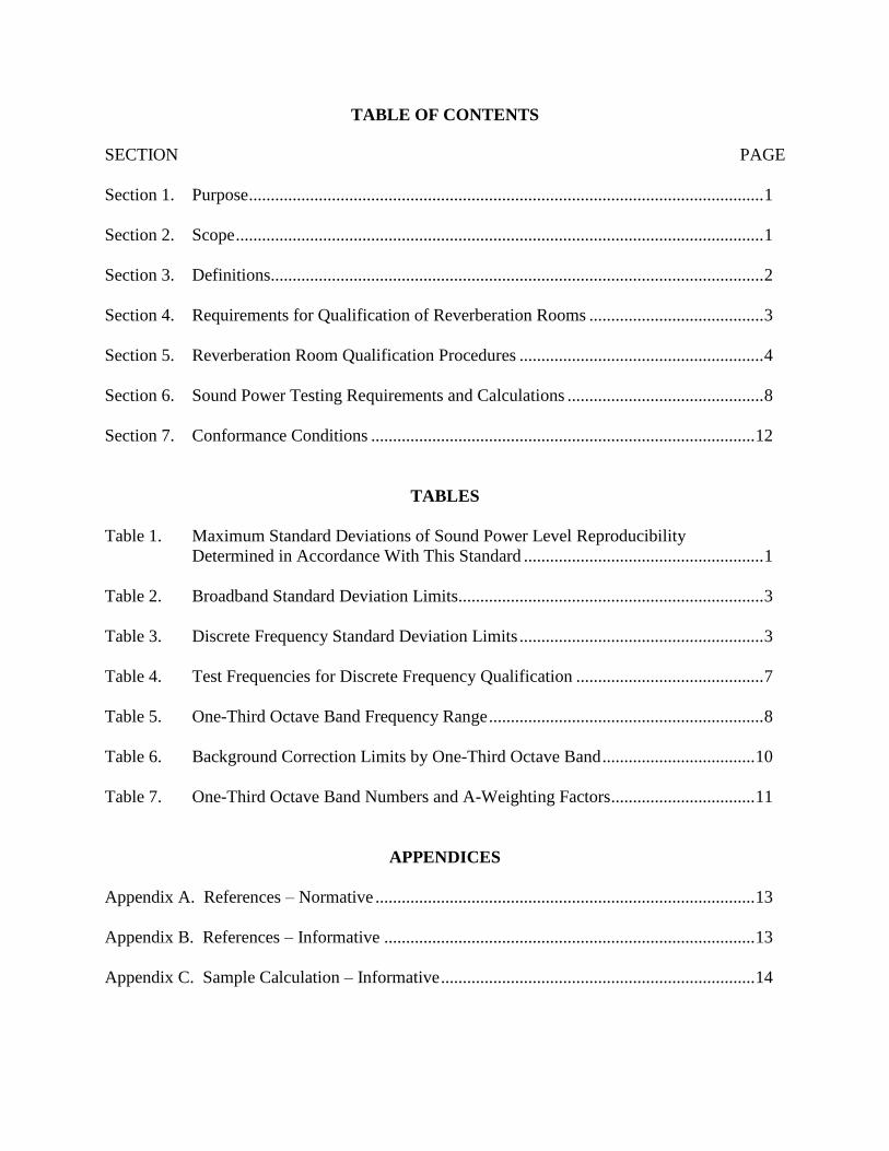
TABLE OF CONTENTS
SECTION PAGE
Section 1. Purpose ...................................................................................................................... 1
Section 2. Scope ......................................................................................................................... 1
Section 3. Definitions................................................................................................................. 2
Section 4. Requirements for Qualification of Reverberation Rooms ........................................ 3
Section 5. Reverberation Room Qualification Procedures ........................................................ 4
Section 6. Sound Power Testing Requirements and Calculations ............................................. 8
Section 7. Conformance Conditions ........................................................................................ 12
TABLES
Table 1. Maximum Standard Deviations of Sound Power Level Reproducibility
Determined in Accordance With This Standard ....................................................... 1
Table 2. Broadband Standard Deviation Limits...................................................................... 3
Table 3. Discrete Frequency Standard Deviation Limits ........................................................ 3
Table 4. Test Frequencies for Discrete Frequency Qualification ........................................... 7
Table 5. One-Third Octave Band Frequency Range ............................................................... 8
Table 6. Background Correction Limits by One-Third Octave Band ................................... 10
Table 7. One-Third Octave Band Numbers and A-Weighting Factors ................................. 11
APPENDICES
Appendix A. References – Normative ....................................................................................... 13
Appendix B. References – Informative ..................................................................................... 13
Appendix C. Sample Calculation – Informative ........................................................................ 14


AHRI STANDARD 220-2007
1
REVERBERATION ROOM QUALIFICATION AND TESTING PROCEDURES FOR DETERMINING SOUND POWER OF
HVAC EQUIPMENT
Section 1. Purpose
1.1 Purpose. The purpose of this standard is to provide the methodology for the determination of Sound Power Levels of
noise sources that emit Broadband Sound and/or Discrete Frequency Sounds/Tones in reverberation rooms. The method
described herein requires reverberation room pre-qualification through test and the use of the Comparison Method to
determine Sound Power Levels. This standard specifies the physical environment, procedures, and equipment used to qualify
the reverberation room by test. Pre-qualifying the room ensures adequate modal density with the use of one source locations
to obtain acceptable accuracy and repeatability of results. The Reference Sound Source used for the Comparison Method
relies on AHRI Standard 250 to accurately calibrate the RSS at all frequencies of interest. Sound rating values are often
useful for applications and design, therefore it is important to acquire data and qualify measurement rooms in One-Third
Octave Bands. The use of the Comparison Method reduces a number of potential sources of error. The standard contains
information on instrumentation, installation and operation of the source, procedures for determining the number of
microphone positions or length of traverse, and procedures for the calculation of Sound Power Level. Measurements made in
conformity with this standard will, with very few exceptions, result in standard deviations equal to or less than specified in
Table 1.
The frequencies covered in this standard range from the 50 Hz to the 10,000 Hz One-Third Octave Band (63 Hz to 8000 Hz
Octave Bands). The 50 to 80 Hz one-third octave band sound for HVAC equipment affects product applications and often
cannot be ignored. The product specific AHRI standard will specify the frequency range of interest for qualification,
calculation, and reporting. This standard is based on ANSI S12.51/ISO: 3741 but provides additional exceptions and
extensions.
Table 1. Maximum Standard Deviations of Sound Power Level Reproducibility Determined in Accordance With This Standard
One-Third Octave Band Center Frequency, Hz
One-Third Octave Band Maximum Standard Deviation of
Reproducibility, σR0, dB
50 - 80 4.0
100 - 160 3.0
200 - 315 2.0
400 - 5000 1.5
6000 - 10000 3.0
1.1.1 Intent. This standard is intended for the guidance of the industry, including manufacturers, engineers,
installers, contractors and users.
1.1.2 Review and Amendment. This standard is subject to review and amendment as technology advances.
Section 2. Scope
2.1 Scope. This standard applies to HVAC products where sound power is determined by measurement using the
Comparison Method in a reverberation room that meets the qualification requirements of this standard.

AHRI STANDARD 220-2007 ___________________________________________________________________
2
Section 3. Definitions
All terms in this document follow standard industry definitions in the current edition of ASHRAE Terminology of Heating,
Ventilation, Air Conditioning and Refrigeration unless otherwise defined in this section.
3.1 Broadband Sound. Sound that is random in nature with frequency components distributed over a broad frequency
band. Typically pure tones or periodic disturbances will not be distinguishable in this type of sound spectrum.
3.2 Comparison Method. A method of determining Sound Power Level by comparing the average Sound Pressure Level
produced in the room to a Reference Sound Source of known sound power level output. The difference in Sound Power
Level is equal to the difference in Sound Pressure Level when conditions in the room are the same for both sets of
measurements.
3.3 Direct Method. A method of determining sound power level from the measured sound pressure levels produced by the
source under test in a reverberation room and from the reverberation time and volume of the reverberation room.
3.4 Discrete Frequency Sounds/Tones. These consist of one or more sound waves, each of which is essentially sinusoidal.
3.5 Discrete Frequency Source. A noise source that produces Discrete Frequency Sounds/Tones.
3.6 Low Frequency Data. Data in the 63 Hz Octave Band (50, 63, and 80 Hz One-Third Octave Bands).
3.7 Octave Band. A band of sound covering a range of frequencies such that the highest is twice the lowest. The Octave
Bands used in this standard are those defined in ANSI Standard S1.11.
3.8 One-Third Octave Band. A band of sound covering a range of frequencies such that the highest frequency is the cube
root of two times the lowest frequency. The One-Third Octave Bands used in this standard are those defined in ANSI
Standard S1.11.
3.9 Reference Sound Source (RSS). A portable, aerodynamic sound source that produces a known stable broadband sound
power output.
3.10 "Shall" or "Should." "Shall" or "should" shall be interpreted as follows:
3.10.1 Shall. Where "shall" or "shall not" is used for a provision specified, that provision is mandatory if
compliance with the standard is claimed.
3.10.2 Should. "Should" is used to indicate provisions which are not mandatory but which are desirable as good
practice.
3.11 Sound Power Level, Lw. Ten times the logarithm to the base ten of the ratio of the sound power radiated by the source
to a reference sound power, expressed in decibels (dB). The reference sound power used in this standard is 1 picowatt (pW).
3.11.1 A-Weighted Sound Power Level (LwA). The logarithmic summation of A-weighted, one-third octave band
Sound Power Levels.
3.12 Sound Pressure Level, Lp. Twenty times the logarithm to the base ten of the ratio of a given sound pressure to a
reference sound pressure of 20 µ Pa, expressed in decibels (dB).
3.13 Unit Under Test (UUT). HVAC equipment or duct termination for which the sound power is to be determined.

AHRI STANDARD 220-2007
3
Section 4. Requirements for Qualification of Reverberation Rooms
4.1 Reverberation Room Requirements. The acoustic and physical environment of the reverberation room shall be
qualified by test to meet the requirements of ANSI Standard S12.51/ISO: 3741 Sections 5.1, 5.5, Annex A, Annex E, and
Annex D except as noted in Sections 4.3 and 4.4 and the room volume requirements below. The minimum room volume for
qualification of frequencies below the 100 Hz One-Third Octave Band shall be 280 m3. If only One-Third Octave Bands
equal to and above 100 Hz are required, the minimum room volume shall be 200 m3.
4.2 Instrumentation Requirements. Instrumentation shall meet or exceed the requirements of Class 1 as specified in ANSI
Standard S1.4. over the frequency range of interest. The microphone(s) used for all measurements shall be of the diffuse
field/random incident type.
4.3 Standard Deviation Requirements for Broadband Room Qualification. The requirements of this standard for
broadband room qualification are:
Table 2. Broadband Standard Deviation Limits
Octave Band
Center
Frequency (Hz)
One-Third
Octave Band
Frequency (Hz)
Standard
Deviation Ss
(dB)
63
125
250
500
1000
2000
4000
8000
50, 63, 80
100, 125, 160
200, 250, 315
400, 500, 630
800, 1000, 1250
1600, 2000, 2500
3150, 4000, 5000
6300, 8000, 10000
2.0
1.5
1.0
1.0
0.5
0.5
1.0
1.0
4.3.1 Broadband Source. For the purposes of this standard, the RSS used to broadband qualify the reverberation
room shall meet the requirements of AHRI Standard 250.
4.4 Standard Deviation Requirements for Discrete Frequency Room Qualification. The requirements of this standard for
discrete-frequency room qualification are:
Table 3. Discrete Frequency Standard Deviation Limits
Octave Band
Center
Frequency (Hz)
One-Third
Octave Band
Frequency (Hz)
Standard
Deviation Ss
(dB)
63
125
250
500
1000
2000
50, 63, 80
100, 125, 160
200, 250, 315
400, 500, 630
800, 1000, 1250
1600, 2000, 2500
4.0
3.0
2.0
1.5
1.0
1.0

AHRI STANDARD 220-2007 ___________________________________________________________________
4
4.4.1 Discrete Frequency Source. For the purposes of this standard, the Discrete Frequency Source used to qualify
the reverberation room shall meet the requirements of Section 5.2.2 .
4.5 Microphone locations. No microphone position or point on a traverse shall be less than 1.5 m from any of the
reverberation room’s surfaces. At no point shall the microphone be any closer than 0.5 m to any surface on a rotating
diffuser. The minimum distance (in meters) between the microphone and each measurement location shall be determined
from the equation below:
1
Where:
dmin = Minimum distance between the microphone and source, meters
D2 = 0.4 for One-Third Octave Bands from 50 Hz to 80 Hz and from 6300 Hz to 10,000 Hz
= 0.8 for One-Third Octave Bands from 100 Hz to 5000 Hz
Lwr = The calibrated Sound Power Level of the RSS in any One-Third Octave Band
Lpr = The measured Sound Pressure Level of the RSS in any One-Third Octave Band
The dmin shall be computed for each One-Third Octave Band and each potential source location for which the room is to be
qualified. The maximum calculated dmin value shall be the minimum distance between the microphone and the source for
room qualification and for unit testing.
4.6 Microphone Traverse. If a traversing microphone is used, the space averaging of the sound data shall be measured
using a microphone traversing at a constant speed over a path length greater than or equal to 3λ for One-Third Octave Bands
of 100 Hz and above and 3λ/2 for the 50 Hz through 80 Hz One-Third Octave Bands, where λ is the wave length of the
lowest mid-band frequency of interest.
4.6.1 Path of Microphone Travel. The path may be a line, semicircle, circle, or other geometric shape. The path of
the microphone traverse shall be repeatable.
4.6.2 Microphone Traverse Speed. The speed of the traversing microphone shall be constant and shall not exceed
1 meter per second. There shall be a whole number of microphone traverses completed during the analyzer’s
measurement time interval, no partial traverses are allowed.
4.6.3 Microphone Traverse Location. The microphone traverse shall be within the reverberant field. The
traversing microphone shall not lie in any plane within 10˚ of any room surface.
4.7 Fixed microphones. An array of at least six fixed microphones (or microphone positions) spaced at least /2 from
each other and located in the reverberant field can be used. The microphones shall not lie in a plane. The outputs of the
microphones shall be either scanned automatically and averaged by the indicating device, or the space average shall be
computed from the Sound Pressure Levels at each individual microphone position.
Section 5. Reverberation Room Qualification Procedures
A reverberation room to be used per this standard shall first be broadband qualified per Section 5.1 and then for discrete
frequencies per Section 5.2. This is required because it is not possible to determine before testing if discrete frequency
contributions to the source spectrum are small enough to only negligibly affect the variation in the resulting sound power
calculation.
5.1 Broadband room qualification. The procedures described in this section shall be used to determine whether the
reverberation room meets one-third octave band broadband requirements for measurement uncertainties as specified in
Section 4.3.
AHRI STANDARD 220-2007
5
5.1.1 Broadband Qualification Test Procedure. The Sound Pressure Levels due to operation of a Reference Sound
Source, calibrated per AHRI Standard 250, shall be measured at eight or more RSS measurement locations (placed so
that the microphone is located in the room’s reverberant field during the RSS operation). The RSS shall be located on
a reflecting plane. The resulting Sound Pressure Levels shall be used to determine the sample standard deviation.
5.1.2 RSS Considerations. For the purposes of this standard, the RSS shall have the characteristics required by
AHRI Standard 250 and be calibrated in accordance with AHRI Standard 250. Each measurement location selected
for the Reference Sound Source shall be such that the distance between any two locations is between ¼ and ½
wavelength of the center frequency of the lowest One-Third Octave Band for which the room or portion thereof is to
be qualified. The selected locations shall be no closer than 1.5 m to any wall and no closer to the microphone than dmin
as described in Section 4.5. Additionally the selected locations shall not be within 0.25 m of the room centerlines.
The locations selected shall be as close as possible to the intended test locations for test units and cover a region
surrounding the test unit or to either side of a test duct. The RSS shall be operated at no more than plus or minus
2 RPM from its calibrated RPM. To prevent the need for background correction and the corresponding added
uncertainty, it is recommended that the RSS Sound Pressure Levels be 15 dB above background levels over the
frequency range of interest,
5.1.3 Data to Be Taken. Data shall be taken at each of the RSS measurement locations in One-Third Octave Bands
over the frequency range as defined in Section 5.1.5. Sound Pressure Levels shall be measured to the nearest 0.1 dB at
each one of the source locations.
5.1.3.1 Analyzer Measurement Time Interval. The sound analyzer measurement time interval shall be equal
to or greater than 30 seconds.
5.1.3.2 Microphone Traverses. The microphone shall make at least two complete traverses during the
measurement time interval. The microphone traverse shall be per Section 4.6.
5.1.3.3 Fixed Microphones. Fixed microphones shall be per Section 4.7.
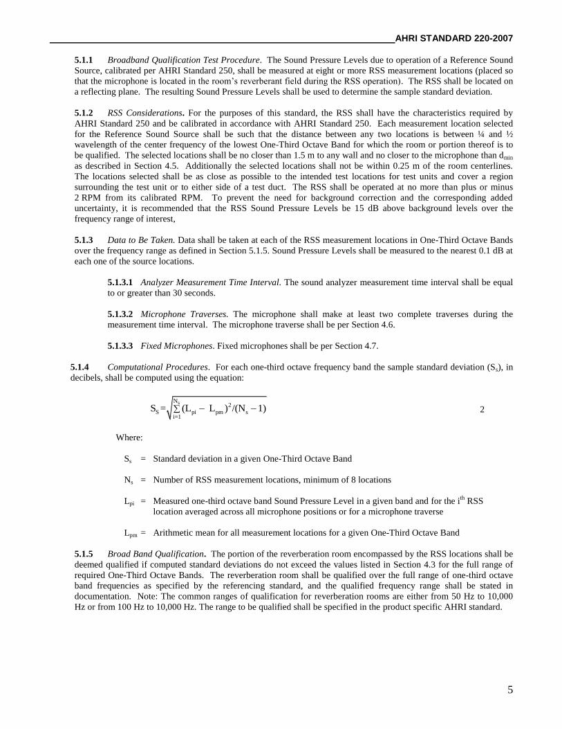
5.1.4 Computational Procedures. For each one-third octave frequency band the sample standard deviation (Ss), in
decibels, shall be computed using the equation:
sN
2
S pi pm si=1
S = (L L ) /(N 1) 2
Where:
Ss = Standard deviation in a given One-Third Octave Band
Ns = Number of RSS measurement locations, minimum of 8 locations
Lpi = Measured one-third octave band Sound Pressure Level in a given band and for the ith
RSS
location averaged across all microphone positions or for a microphone traverse
Lpm = Arithmetic mean for all measurement locations for a given One-Third Octave Band
5.1.5 Broad Band Qualification. The portion of the reverberation room encompassed by the RSS locations shall be
deemed qualified if computed standard deviations do not exceed the values listed in Section 4.3 for the full range of
required One-Third Octave Bands. The reverberation room shall be qualified over the full range of one-third octave
band frequencies as specified by the referencing standard, and the qualified frequency range shall be stated in
documentation. Note: The common ranges of qualification for reverberation rooms are either from 50 Hz to 10,000
Hz or from 100 Hz to 10,000 Hz. The range to be qualified shall be specified in the product specific AHRI standard.

AHRI STANDARD 220-2007 ___________________________________________________________________
6
5.1.6 Additional. Once the region of the reverberation room is qualified; the microphone traverse or fixed
microphone positions, sound diffuser (if used) instrumentation, and analyzer measurement time interval shall be
identical to those used when performing unit testing in order to claim compliance with this standard. Sound diffuser
design is recommended per ANSI S12.51/ISO: 3741 Annex B.
5.2 Discrete Frequency Room Qualification. Procedures described in this section shall be used to determine whether the
portion of the reverberation room to be used in subsequent tests meets the one-third octave band discrete frequency
requirements for measurement uncertainties as specified is Section 4.4. The broadband room qualification procedure shall be
completed first so that the location for the test is shown to be one-third octave band broadband qualified prior to doing the
discrete frequency room qualification. For the purposes of Section 5.2, the Discrete Frequency Source is a speaker.
5.2.1 Discrete Frequency Test Procedure. One (or more) measurement location(s) as specified in Section 5.2.4
shall be used to determine the sample standard deviation of the measured Sound Pressure Levels as calculated per
Section 5.2.8. Multiple locations shall be qualified if the test source is large. The area between qualified sources
defines the qualified region. The device under test shall be placed within the qualified region. Each location shall be
qualified individually. The microphone traverse or fixed microphones, sound diffuser (if used) instrumentation, and
analyzer measurement time interval shall be that used in the broadband room qualification procedure of Section 5.1.
The one-third octave band upper frequency limit for discrete frequency testing shall be determined from Section 5.2.7.
5.2.2 Discrete Frequency Source and Operational Equipment. The Discrete Frequency Source and its operational
equipment shall meet the requirements of ANSI S12.51/ISO: 3741 Annex A.3. The exception is that when qualifying
the 50, 63, and 80 Hz One-Third Octave Bands, use of a speaker with a diameter greater than 200 mm may be
required, but the diameter shall be no greater than 400 mm.
5.2.3 Speaker Qualification and Normalization. This procedure describes how to qualify the speaker and normalize
the system. Annex A.4 of ANSI S12.51/ISO: 3741 is to be used for this procedure except the microphone and
associated equipment (excluding traverse) used in Section 5.1 shall be used and the Sound Pressure Levels are to be
measured to the nearest 0.1 dB. If fixed microphones are to be used, it is recommended that the sound level be
measured for each microphone and associated cable and/or windscreen. These Sound Pressure Levels shall be
designated Lpia. The difference between levels of adjacent tones within a given One-Third Octave Band is
recommended to be less than or equal to 1 dB for frequencies in the 100 Hz One-Third Octave Band and above and 2
dB for frequencies below the 100 Hz One-Third Octave Band. If the reverberation room’s microphone(s) requires that
a microphone windscreen be used, then that windscreen shall be installed on the microphone when doing the speaker
qualification and normalization. Additionally, the windscreen shall meet the requirements specified in Section 5.10 of
AHRI Standard 250.
5.2.4 Discrete Frequency Source Speaker Location(s). The speaker(s) shall be located at the broadband qualified
location(s) and within the boundary created by the broadband qualified locations. The cone of the speaker(s) shall be
oriented so that it points away from the nearest reflecting plane.
5.2.5 Discrete Test Frequencies. The discrete test frequencies that are used for a reverberation room’s discrete
frequency room qualification are listed in Table 4.

AHRI STANDARD 220-2007
7
Table 4. Test Frequencies for Discrete Frequency Qualification
50 63 80 100 125 160 200 250 315 400 500 630 800 1000 1250 1600 2000 2500
----- ----- ----- ----- ----- 147 ----- ----- ----- 361 ----- ----- ----- ----- ----- 1470 ----- -----
----- ----- ----- ----- 113 148 ----- 226 ----- 364 ----- ----- ----- ----- 1130 1480 ----- 2260
----- 56.4 71.2 ----- 114 149 ----- 228 ----- 367 ----- 564 712 ----- 1140 1490 ----- 2280
45.0 57.0 72.0 90 115 150 180 230 285 370 450 570 720 900 1150 1500 1800 2300
45.5 57.6 72.8 91 116 151 182 232 288 373 455 576 728 910 1160 1510 1820 2320
46.0 58.2 73.6 92 117 152 184 234 291 376 460 582 736 920 1170 1520 1840 2340
46.5 58.8 74.4 93 118 153 186 236 294 379 465 588 744 930 1180 1530 1860 2360
47.0 59.4 75.2 94 119 154 188 238 297 382 470 594 752 940 1190 1540 1880 2380
47.5 60.0 76.0 95 120 155 190 240 300 385 475 600 760 950 1200 1550 1900 2400
48.0 60.6 76.8 96 121 156 192 242 303 388 480 606 768 960 1210 1560 1920 2420
48.5 61.2 77.6 97 122 157 194 244 306 391 485 612 776 970 1220 1570 1940 2440
49.0 61.8 78.4 98 123 158 196 246 309 394 490 618 784 980 1230 1580 1960 2460
49.5 62.4 79.2 99 124 159 198 248 312 397 495 624 792 990 1240 1590 1980 2480
50.0 63.0 80.0 100 125 160 200 250 315 400 500 630 800 1000 1250 1600 2000 2500
50.5 63.6 80.8 101 126 161 202 252 318 403 505 636 808 1010 1260 1610 2020 2520
51.0 64.2 81.6 102 127 162 204 254 321 406 510 642 816 1020 1270 1620 2040 2540
51.5 64.8 82.4 103 128 163 206 256 324 409 515 648 824 1030 1280 1630 2060 2560
52.0 65.4 83.2 104 129 164 208 258 327 412 520 654 832 1040 1290 1640 2080 2580
52.5 66.0 84.0 105 130 165 210 260 330 415 525 660 840 1050 1300 1650 2100 2600
53.0 66.6 84.8 106 131 166 212 262 333 418 530 666 848 1060 1310 1660 2120 2620
53.5 67.2 85.6 107 132 167 214 264 336 421 535 672 856 1070 1320 1670 2140 2640
54.0 67.8 86.4 108 133 168 216 266 339 424 540 678 864 1080 1330 1680 2160 2660
54.5 68.4 87.2 109 134 169 218 268 342 427 545 684 872 1090 1340 1690 2180 2680
55.0 69.0 88.0 110 135 170 220 270 345 430 550 690 880 1100 1350 1700 2200 2700
55.5 69.6 88.8 111 136 171 222 272 348 433 555 696 888 1110 1360 1710 2220 2720
56.0 70.2 ----- ----- 137 172 ----- 274 ----- 436 560 702 ----- ----- 1370 1720 ----- 2740
----- ----- ----- ----- 138 173 ----- 276 ----- 439 ----- ----- ----- ----- 1380 1730 ----- 2760
One-Third Octave Band Center Frequencies
5.2.6 Discrete Frequency Testing. At each required discrete test frequency, the speaker shall be operated at the
same voltage that was used in Section 5.2.3. With the instrumentation as stated in Section 5.2.1 operating normally,
one-third octave band Sound Pressure Levels shall be measured in the reverberation room at each one of the required
test frequencies. The voltage measured at the speaker shall not vary by more than plus or minus 0.1% and the
frequency shall not vary by more than plus or minus 0.1Hz during sound pressure level measurements at each one of
the test frequencies. For each of the required One-Third Octave Bands, the full set of test frequencies identified in
Table 4 shall be measured. These Sound Pressure Levels shall be designated, Lpir.
5.2.7 Determining Upper Frequency Qualification Limit. The upper frequency limit of required testing shall be
determined as specified below and shall not be greater than the maximum frequency listed for the 2500 Hz One-Third
Octave Band in Table 4. Calculate the frequency limit using both equations below. Using the larger of the two
calculated frequency limit values, determine the One-Third Octave Band for which the frequency limit falls between
the lower band limit and upper band limit in Table 5. If fixed microphones are used, the limit shall be determined
using the room volume relationship. The qualification shall cover the bands up through the entire band containing the
frequency limit.
Frequency Limit = 6000 / L 3
or
Frequency Limit = 5000 / V1/3
4
Where:
L = Length of one complete microphone traverse, m
V = Volume of the reverberation room, m3

AHRI STANDARD 220-2007 ___________________________________________________________________
8
Table 5. One-Third Octave Band Frequency Range
Center
Frequency 50 63 80 100 125 160 200 250 315 400 500 630 800 1000 1250 1600 2000 2500
Lower
Band Limit 44.7 56.2 70.8 89.1 112 141 178 224 282 354 447 562 707 891 1122 1414 1778 2239
Upper
Band Limit 56.2 70.8 89.1 112 141 178 224 282 354 447 562 707 891 1122 1414 1778 2239 2828
One-Third Octave Band Frequencies
Source of Table 5: ANSI Standard S1.6
5.2.8 Computational Procedures. For each One-Third Octave Band, the measured Sound Pressure Level for each
tone shall be corrected for room response as follows:
piq pia pirL = L L 5
Where:
Lpia = Sound Pressure Level measured near the speaker from Section 5.2.3
Lpiq = Measured one-third octave band Sound Pressure Level in a given band and for a given speaker
location that has been corrected for speaker response
Lpir = Sound Pressure Level measured in the reverberation room from Section 5.2.6
The sample standard deviation (Sf), dB, shall be computed using the equation:
f 2
fpiq pmqff 1
N/ 1Ns L L
6
Where:
Sf = Standard deviation in a given One-Third Octave Band
Nf = Number of measurement frequencies in a given One-Third Octave Band
Lpmq = Arithmetic mean of the corrected Sound Pressure Level for all test frequencies for a given
One-Third Octave Band
5.2.9 Discrete Frequency Qualification. The reverberation room shall be deemed qualified if the computed
standard deviations do not exceed the values listed in Section 4.4 for the full range of One-Third Octave Bands. The
reverberation room shall be qualified over the full range of one-third octave band frequencies as specified by the
referencing AHRI standard, and the qualified frequency range must be stated in documentation.
5.2.10 Additional. Once the reverberation room is qualified; the microphone traverse or positions, sound diffuser (if
used), windscreen, instrumentation and analyzer observation times shall be identical when doing unit testing in order
to claim compliance with this standard. Sound diffuser design is recommended to be per ANSI S12.51/ISO 3741
Annex B.
Section 6. Sound Power Testing Requirements and Calculations
Sound Pressure Levels of the Reference Sound Source, background sound, and the UUT shall be measured using the same
microphone traverse or positions, sound diffuser (if used), windscreen, instrumentation, and analyzer observation times as
were used for broadband and discrete frequency qualifications.
6.1 Volume of Unit UnderTest. The volume of the UUT shall be no more than 5% of the room volume.
AHRI STANDARD 220-2007
9
6.2 Location of Unit Under Test. Measurements shall be carried out with the UUT at a location within the area qualified
per Sections 4 and 5.
6.3 RSS Considerations. For the purposes of this standard, the RSS shall have the characteristics required by AHRI
Standard 250 and be calibrated in accordance with AHRI Standard 250. The RSS shall be placed at a broadband qualified
location 1.5 meters from the UUT. The RSS shall be operated at no more than plus or minus 2 RPM from its calibrated RPM.
To prevent the need for background correction and the corresponding added uncertainty, it is recommended that the RSS
Sound Pressure Levels be 15 dB above background levels over the frequency range of interest. However, the RSS shall be at
least 6 dB above background for One-Third Octave Bands from 50 to 315 Hz and from 6,300 to 10,000 Hz and at least 10 dB
for One-Third Octave Bands with frequencies between 400 and 5,000 Hz.
6.4 Measurements. Measurements of the UUT, RSS, and background Sound Pressure Levels shall be made in terms of
One-Third Octave Bands to the nearest 0.1 dB.
6.5 One-Third Octave Band Sound Power Level Calculations. One-third octave band sound power level calculations shall
be per Equation 9, rounded to the nearest 0.1 dB. The un-rounded one-third octave band Sound Pressure Level, as measured
in the room for the UUT, and the un-rounded one-third octave band Sound Pressure Level, as measured in the room for the
RSS, shall be corrected for background following Equation 7. The background limits and corrections are as indicated in
Table 6. If the difference between the background and measured level is less than the limits shown in Table 6, the values
may be reported but shall be identified as being influenced by the background and potentially having a higher uncertainty
than described in Section 1.1. Note that when the differences between the background and UUT Sound Pressure Levels are
less than those shown in Table 6, the resulting Sound Power Level will be conservative and the designation in any published
results shall make it clear that it is an upper limit. All calculations shall be based on un-rounded one-third octave band levels.
Appendix C shows a sample calculation. When determining octave band levels (unless directed otherwise in the product
specific standard), the octave band level shall be identified as being influenced by background sound if any of the
background limited One-Third Octave Band(s) contribute 0.5 dB or more to the octave band level.
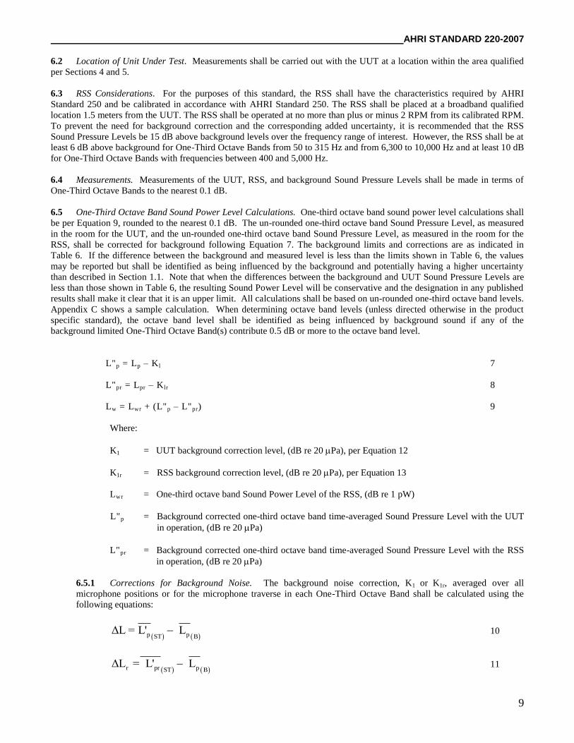
L"p = Lp – Kl 7
L"pr = Lpr – Klr 8
Lw = Lwr + (L"p – L"pr) 9
Where:
K1 = UUT background correction level, (dB re 20 Pa), per Equation 12
K1r = RSS background correction level, (dB re 20 Pa), per Equation 13
Lwr = One-third octave band Sound Power Level of the RSS, (dB re 1 pW)
L"p = Background corrected one-third octave band time-averaged Sound Pressure Level with the UUT
in operation, (dB re 20 Pa)
L"pr = Background corrected one-third octave band time-averaged Sound Pressure Level with the RSS
in operation, (dB re 20 Pa)
6.5.1 Corrections for Background Noise. The background noise correction, K1 or K1r, averaged over all
microphone positions or for the microphone traverse in each One-Third Octave Band shall be calculated using the
following equations:
p pST BΔL = L' L 10
r pr pST BΔL = L' L 11
AHRI STANDARD 220-2007 ___________________________________________________________________
10
-0.1ΔL
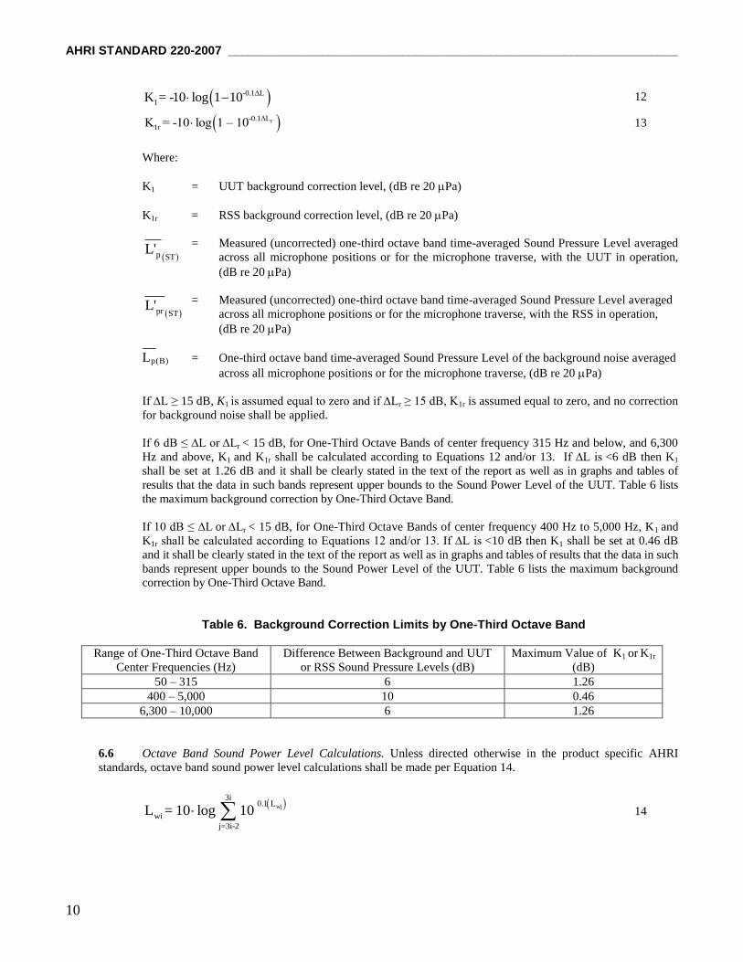
1K = -10 log 1 10 12
r-0.1ΔL
1rK = -10 log 1 – 10 13
Where:
K1 = UUT background correction level, (dB re 20 Pa)
K1r = RSS background correction level, (dB re 20 Pa)
= Measured (uncorrected) one-third octave band time-averaged Sound Pressure Level averaged
across all microphone positions or for the microphone traverse, with the UUT in operation,
(dB re 20 Pa)
= Measured (uncorrected) one-third octave band time-averaged Sound Pressure Level averaged
across all microphone positions or for the microphone traverse, with the RSS in operation,
(dB re 20 Pa)
Lp(B) = One-third octave band time-averaged Sound Pressure Level of the background noise averaged
across all microphone positions or for the microphone traverse, (dB re 20 Pa)
If ∆L ≥ 15 dB, K1 is assumed equal to zero and if ∆Lr ≥ 15 dB, K1r is assumed equal to zero, and no correction
for background noise shall be applied.
If 6 dB ≤ ∆L or ∆Lr < 15 dB, for One-Third Octave Bands of center frequency 315 Hz and below, and 6,300
Hz and above, K1 and K1r shall be calculated according to Equations 12 and/or 13. If ∆L is <6 dB then K1
shall be set at 1.26 dB and it shall be clearly stated in the text of the report as well as in graphs and tables of
results that the data in such bands represent upper bounds to the Sound Power Level of the UUT. Table 6 lists
the maximum background correction by One-Third Octave Band.
If 10 dB ≤ ∆L or ∆Lr < 15 dB, for One-Third Octave Bands of center frequency 400 Hz to 5,000 Hz, K1 and
K1r shall be calculated according to Equations 12 and/or 13. If ∆L is <10 dB then K1 shall be set at 0.46 dB
and it shall be clearly stated in the text of the report as well as in graphs and tables of results that the data in such
bands represent upper bounds to the Sound Power Level of the UUT. Table 6 lists the maximum background
correction by One-Third Octave Band.
Table 6. Background Correction Limits by One-Third Octave Band
Range of One-Third Octave Band
Center Frequencies (Hz)
Difference Between Background and UUT
or RSS Sound Pressure Levels (dB)
Maximum Value of K1 or K1r
(dB)
50 – 315 6 1.26
400 – 5,000 10 0.46
6,300 – 10,000 6 1.26
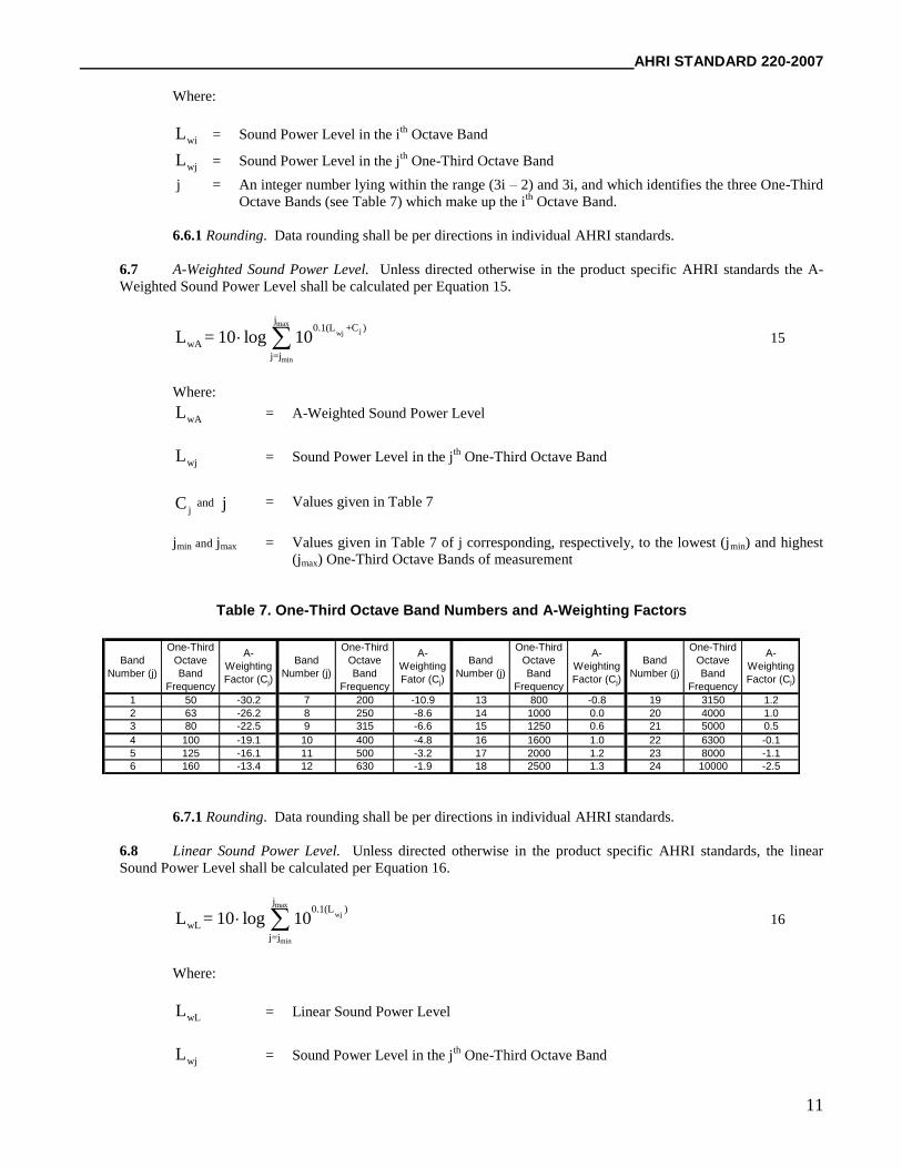
6.6 Octave Band Sound Power Level Calculations. Unless directed otherwise in the product specific AHRI
standards, octave band sound power level calculations shall be made per Equation 14.
wj
3i0.1 L
wi
j=3i-2
L = 10 log 10 14
pr STL'
p STL'
AHRI STANDARD 220-2007
11
Where:
wiL = Sound Power Level in the ith
Octave Band
wjL = Sound Power Level in the jth
One-Third Octave Band
j = An integer number lying within the range (3i – 2) and 3i, and which identifies the three One-Third
Octave Bands (see Table 7) which make up the ith
Octave Band.
6.6.1 Rounding. Data rounding shall be per directions in individual AHRI standards.
6.7 A-Weighted Sound Power Level. Unless directed otherwise in the product specific AHRI standards the A-
Weighted Sound Power Level shall be calculated per Equation 15.
maxjwj
min
j0.1(L +C )
wA
j=j
L = 10 log 10 15
Where:
wAL = A-Weighted Sound Power Level
wjL = Sound Power Level in the jth
One-Third Octave Band
jC and j = Values given in Table 7
jmin and jmax = Values given in Table 7 of j corresponding, respectively, to the lowest (jmin) and highest
(jmax) One-Third Octave Bands of measurement
Table 7. One-Third Octave Band Numbers and A-Weighting Factors
Band
Number (j)
One-Third
Octave
Band
Frequency
A-
Weighting
Factor (Cj)
Band
Number (j)
One-Third
Octave
Band
Frequency
A-
Weighting
Fator (Cj)
Band
Number (j)
One-Third
Octave
Band
Frequency
A-
Weighting
Factor (Cj)
Band
Number (j)
One-Third
Octave
Band
Frequency
A-
Weighting
Factor (Cj)
1 50 -30.2 7 200 -10.9 13 800 -0.8 19 3150 1.2
2 63 -26.2 8 250 -8.6 14 1000 0.0 20 4000 1.0
3 80 -22.5 9 315 -6.6 15 1250 0.6 21 5000 0.5
4 100 -19.1 10 400 -4.8 16 1600 1.0 22 6300 -0.1
5 125 -16.1 11 500 -3.2 17 2000 1.2 23 8000 -1.1
6 160 -13.4 12 630 -1.9 18 2500 1.3 24 10000 -2.5
6.7.1 Rounding. Data rounding shall be per directions in individual AHRI standards.
6.8 Linear Sound Power Level. Unless directed otherwise in the product specific AHRI standards, the linear
Sound Power Level shall be calculated per Equation 16.
max
wj
min
j0.1(L )
wL
j=j
L = 10 log 10 16
Where:
wLL = Linear Sound Power Level
wjL = Sound Power Level in the jth
One-Third Octave Band
AHRI STANDARD 220-2007 ___________________________________________________________________
12
j = Given in Table 7
jmin and jmax = Values given in Table 7 of j corresponding, respectively, to the lowest (jmin) and highest
(jmax) One-Third Octave Bands of measurement
6.8.1 Rounding. Data rounding shall be per directions in individual AHRI standards.
Section 7. Conformance Conditions
7.1 Conformance. While conformance with this standard is voluntary, conformance shall not be claimed or implied for
products or equipment within the standard’s Purpose (Section 1) and Scope (Section 2) unless such product claims meet all
of the requirements of the standard and all of the testing and rating requirements are measured and reported in complete
compliance with the standard. Any product that has not met all the requirements of the standard cannot reference, state, or
acknowledge the standard in any written, oral, or electronic communication.
AHRI STANDARD 220-2007
13
APPENDIX A. REFERENCES – NORMATIVE A1 Listed here are all the standards, handbooks, and other publications essential to the formation and implementation of
the standard. All references in this appendix are considered part of this standard.
A1.1 ANSI Standard S1.4-1983 (R 2006) American National Standard Specification for Sound Level Meters.
American National Standards Institute, 25 West 43rd Street, 4th Fl., New York, NY 10036, U.S.A.
A1.2 ANSI Standard S1.6-1984 (R 2006) American National Standard Preferred Frequencies, Frequency Levels,
and Band Numbers for Acoustical Measurements. American National Standards Institute, 25 West 43rd Street, 4th Fl.,
New York, NY 10036, U.S.A.
A1.3 ANSI Standard S1.11-2004, Specification for Octave-Band and Fractional Octave-Band Analog and Digital
Filters, American National Standards Institute, 25 West 43rd Street, 4th Fl., New York, NY 10036, U.S.A.
A1.4 ANSI S12.51-2002/ISO:3741:1999, Acoustics — Determination of sound power levels of noise sources using
sound pressure — Precision method for reverberation rooms, Nationally Adopted International Standard (NAIS
Standard) American National Standards Institute, 25 West 43rd Street, 4th Fl., New York, NY 10036, U.S.A.
A1.5 AHRI Standard 250-2001 (formerly ARI Standard 250-2001), Performance and Calibration of Reference
Sound Sources, 2001, Air-Conditioning and Refrigeration Institute, 2111 Wilson Boulevard, Suite 500, Arlington, VA
22201, U.S.A.
A1.6 ASHRAE Terminology of Heating, Ventilating, Air-Conditioning and Refrigeration, Second Edition, 1991,
American Society of Heating, Refrigerating, and Air-Conditioning Engineers, Inc., 1791 Tullie Circle, N.E. Atlanta,
GA 30329, U.S.A.
APPENDIX B. REFERENCES – INFORMATIVE
None.
AHRI STANDARD 220-2007 ___________________________________________________________________
14
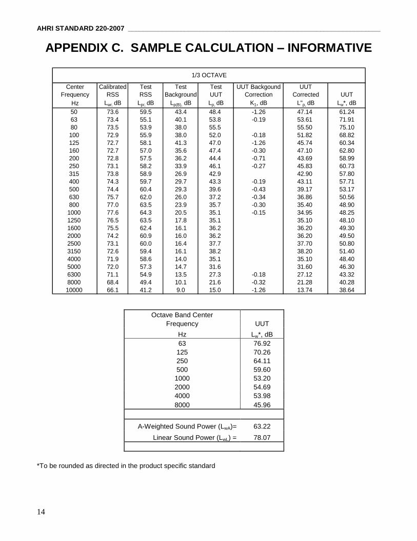
APPENDIX C. SAMPLE CALCULATION – INFORMATIVE
Center Calibrated Test Test Test UUT Backgound UUT
Frequency RSS RSS Background UUT Correction Corrected UUT
Hz Lwr, dB Lpr, dB Lp(B), dB Lp, dB K1, dB L"p, dB Lw*, dB
50 73.6 59.5 43.4 48.4 -1.26 47.14 61.24
63 73.4 55.1 40.1 53.8 -0.19 53.61 71.91
80 73.5 53.9 38.0 55.5 55.50 75.10
100 72.9 55.9 38.0 52.0 -0.18 51.82 68.82
125 72.7 58.1 41.3 47.0 -1.26 45.74 60.34
160 72.7 57.0 35.6 47.4 -0.30 47.10 62.80
200 72.8 57.5 36.2 44.4 -0.71 43.69 58.99
250 73.1 58.2 33.9 46.1 -0.27 45.83 60.73
315 73.8 58.9 26.9 42.9 42.90 57.80
400 74.3 59.7 29.7 43.3 -0.19 43.11 57.71
500 74.4 60.4 29.3 39.6 -0.43 39.17 53.17
630 75.7 62.0 26.0 37.2 -0.34 36.86 50.56
800 77.0 63.5 23.9 35.7 -0.30 35.40 48.90
1000 77.6 64.3 20.5 35.1 -0.15 34.95 48.25
1250 76.5 63.5 17.8 35.1 35.10 48.10
1600 75.5 62.4 16.1 36.2 36.20 49.30
2000 74.2 60.9 16.0 36.2 36.20 49.50
2500 73.1 60.0 16.4 37.7 37.70 50.80
3150 72.6 59.4 16.1 38.2 38.20 51.40
4000 71.9 58.6 14.0 35.1 35.10 48.40
5000 72.0 57.3 14.7 31.6 31.60 46.30
6300 71.1 54.9 13.5 27.3 -0.18 27.12 43.32
8000 68.4 49.4 10.1 21.6 -0.32 21.28 40.28
10000 66.1 41.2 9.0 15.0 -1.26 13.74 38.64
Center Test
Frequency Unit
Hz Lw*, dB
63 76.92
O 125 70.26
C 250 64.11
T 500 59.60
A 1000 53.20
V 2000 54.69
E 4000 53.98
8000 45.96
A-Weighted Lw (LWA)= 63.22
Linear Lw (LWL) = 78.07
1/3 OCTAVE
*To be rounded as directed in the product specific standard
Octave Band Center
Frequency UUT
Hz Lw*, dB
63 76.92
125 70.26
250 64.11
500 59.60
1000 53.20
2000 54.69
4000 53.98
8000 45.96
A-Weighted Sound Power (LwA)= 63.22
Linear Sound Power (LwL) = 78.07