Embed Size (px)
Citation preview
IMPORTANT: READ AND SAVE THESE INSTRUCTIONS!INSTALLATION, OPERATION, AND MAINTENANCE MANUAL
Hydronic Air Handler
AHU 50/70
Air Handler Unit 50 / Air Handler Unit 706 72
0 81
9 39
1 (2
016/
06) U
S
2 | Table of contents
Table of contents
1 Key to symbols and safety instructions . . . . . . . . . . 31.1 Key to symbols . . . . . . . . . . . . . . . . . . . . . . . 31.2 Safety instructions . . . . . . . . . . . . . . . . . . . . 3
2 Appliance details . . . . . . . . . . . . . . . . . . . . . . . . . . . . . 52.1 Introduction . . . . . . . . . . . . . . . . . . . . . . . . . . 52.2 Codes and Standards . . . . . . . . . . . . . . . . . . 52.3 Pump Timer . . . . . . . . . . . . . . . . . . . . . . . . . . 6
3 Receiving and checking equipment . . . . . . . . . . . . . 63.1 Identify unit . . . . . . . . . . . . . . . . . . . . . . . . . . 6
4 Installation instructions . . . . . . . . . . . . . . . . . . . . . . . 64.1 Installation . . . . . . . . . . . . . . . . . . . . . . . . . . . 64.2 Dimensions . . . . . . . . . . . . . . . . . . . . . . . . . . 74.3 Locating and mounting the air handler . . . . 84.4 Closet installation
(return air thru opening or grill) . . . . . . . . . . .94.5 Suspend cabinet installation . . . . . . . . . . . . 94.6 Duct connections . . . . . . . . . . . . . . . . . . . . 104.7 Filter installation . . . . . . . . . . . . . . . . . . . . . 104.8 Air distribution system . . . . . . . . . . . . . . . . 104.9 Examples of Prohibited Installations . . . . . 114.10 Plumbing . . . . . . . . . . . . . . . . . . . . . . . . . . . 114.11 Recommended Piping . . . . . . . . . . . . . . . . . 144.12 Purging and priming the system . . . . . . . . . 144.13 Electrical connections . . . . . . . . . . . . . . . . . 154.14 Selecting fan speeds . . . . . . . . . . . . . . . . . . 184.15 System Configuration . . . . . . . . . . . . . . . . . 184.16 Changing flow restrictors . . . . . . . . . . . . . . 204.17 Thermostat installation . . . . . . . . . . . . . . . . 204.18 Installation considerations . . . . . . . . . . . . . 204.19 Start-up procedure . . . . . . . . . . . . . . . . . . . 204.20 Start-up procedure (cooling system) . . . . . 214.21 Troubleshooting blower and/or pump
motor and controls . . . . . . . . . . . . . . . . . . . 21
5 Sequence of operation . . . . . . . . . . . . . . . . . . . . . . . 215.1 Standby mode . . . . . . . . . . . . . . . . . . . . . . . 215.2 Cooling mode . . . . . . . . . . . . . . . . . . . . . . . . 215.3 Heating mode . . . . . . . . . . . . . . . . . . . . . . . 21
6 Troubleshooting . . . . . . . . . . . . . . . . . . . . . . . . . . . . . 226.1 Most likely problems and causes . . . . . . . . 22
7 Maintenance . . . . . . . . . . . . . . . . . . . . . . . . . . . . . . . . 267.1 Maintenance performed by owner . . . . . . . 267.2 Maintenance performed by service
technician . . . . . . . . . . . . . . . . . . . . . . . . . . .267.3 Air Purging . . . . . . . . . . . . . . . . . . . . . . . . . . 26
8 Air Handler Specifications . . . . . . . . . . . . . . . . . . . . 27
9 Accessories . . . . . . . . . . . . . . . . . . . . . . . . . . . . . . . . 289.1 Field supplied accessories . . . . . . . . . . . . . 28
10 Part List . . . . . . . . . . . . . . . . . . . . . . . . . . . . . . . . . . . . 2910.1 Replacement Parts List . . . . . . . . . . . . . . . . 29
6 720 819 391 (2016/06) Air Handler

Key to symbols and safety instructions | 3
1 Key to symbols and safety instructions
1.1 Key to symbols
Warnings
The following keywords are defined and can be used in this document:• DANGER indicates a hazardous situation which, if not
avoided, will result in death or serious injury.• WARNING indicates a hazardous situation which, if not
avoided, could result in death or serious injury.• CAUTION indicates a hazardous situation which, if not
avoided, could result in minor to moderate injury.• NOTICE is used to address practices not related to
personal injury.
Important information
Additional symbols
1.2 Safety instructionsRead all instructions before installing. Perform the steps in the indicated sequence. Have the Air Handler inspected by a trained service technician at least once every year. Failure to comply with these instructions can result in severe, possibly fatal, personal injury as well as damage to property and equipment.
Installation and servicing▶ Wear safety glasses and work gloves.▶ Risk of fire when soldering and brazing!
Take appropriate protective measures when soldering and brazing around combustible and flammable material.
▶ Suitable fire extinguishing equipment shall be immediately available in the work area and shall be maintained in a state of readiness for instant use.
▶ Use quenching cloth for all brazing and un-brazing operations.
▶ On hot components use only material with adequate temperature stability.
Inspection/maintenance▶ Servicing and repairs may only be carried out by a trained
and certified installer.▶ Immediately correct all faults to prevent system damage.▶ Use only Bosch spare parts!
Instruct the customer▶ Explain to the customer how the appliance works and how
to operate it.▶ Inform the customer that he/she must not carry out any
alterations or repairs.
Danger from electric shock▶ Ensure that only an authorized contractor performs
electrical work.▶ Before performing electrical work, disconnect the power
and secure the unit against unintentional reconnection.▶ Ensure the system has been disconnected from the power
supply.To protect against corrosion and ensure compliance with the rules for electrical safety, observe the following points: ▶ Use metal fittings for potable water heating systems with
plastic piping.▶ Use only original accessories from the manufacturer.▶ When installation of the Air Handler is complete, inspect
the ground conductor (including metal fittings).
Warnings in this document are identified by a warning triangle printed against a grey background.Keywords at the start of a warning indicate the type and seriousness of the ensuing risk if measures to prevent the risk are not taken.
This symbol indicates important information where there is no risk to people or property.
Symbol Explanation▶ Step in an action sequence Cross-reference to another part of the document• List entry– List entry (second level)
Table 1
6 720 819 391 (2016/06)Air Handler
4 | Key to symbols and safety instructions
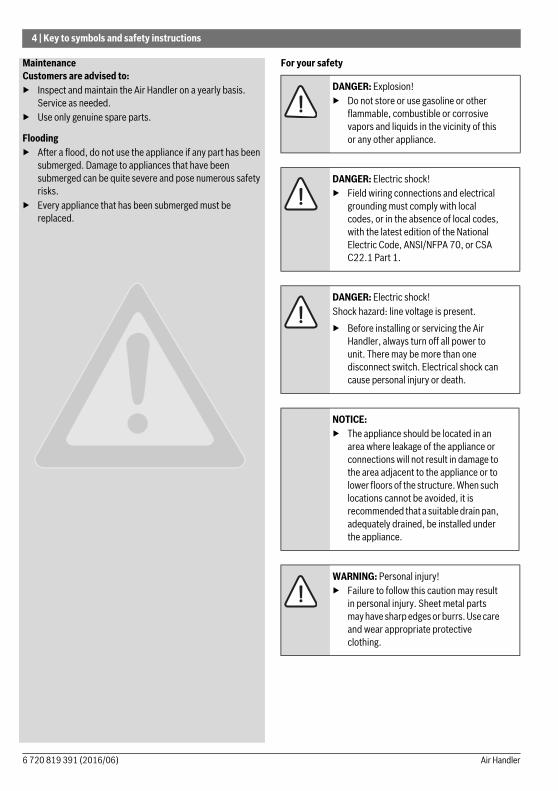
MaintenanceCustomers are advised to:▶ Inspect and maintain the Air Handler on a yearly basis.
Service as needed.▶ Use only genuine spare parts.
Flooding▶ After a flood, do not use the appliance if any part has been
submerged. Damage to appliances that have been submerged can be quite severe and pose numerous safety risks.
▶ Every appliance that has been submerged must be replaced.
For your safety
DANGER: Explosion!▶ Do not store or use gasoline or other
flammable, combustible or corrosive vapors and liquids in the vicinity of this or any other appliance.
DANGER: Electric shock!▶ Field wiring connections and electrical
grounding must comply with local codes, or in the absence of local codes, with the latest edition of the National Electric Code, ANSI/NFPA 70, or CSA C22.1 Part 1.
DANGER: Electric shock!Shock hazard: line voltage is present.▶ Before installing or servicing the Air
Handler, always turn off all power to unit. There may be more than one disconnect switch. Electrical shock can cause personal injury or death.
NOTICE: ▶ The appliance should be located in an
area where leakage of the appliance or connections will not result in damage to the area adjacent to the appliance or to lower floors of the structure. When such locations cannot be avoided, it is recommended that a suitable drain pan, adequately drained, be installed under the appliance.
WARNING: Personal injury!▶ Failure to follow this caution may result
in personal injury. Sheet metal parts may have sharp edges or burrs. Use care and wear appropriate protective clothing.
6 720 819 391 (2016/06) Air Handler
Appliance details | 5
2 Appliance details
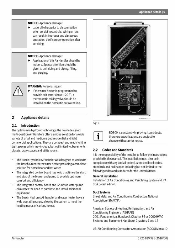
2.1 IntroductionThe optimum in hydronic technology: the newly designed multi-position Air Handlers offer a unique solution for a wide variety of small and medium sized residential and light commercial applications. They are compact and ready to fit in tight spaces which may include, but not limited to, basements, closets, crawlspaces and utility rooms.
• The Bosch Hydronic Air Handler was designed to work with the Bosch Greentherm water heater providing a complete solution for home heat and hot water.
• The integrated control board has logic that times the start and stop of the blower and pump to provide optimum comfort and efficiency.
• The integrated control board and Grundfos water pump eliminates the need to purchase and install additional equipment.
• The Bosch Hydronic Air handler and water heater have a wide operating range, allowing the system to meet the heating needs of various homes.
Fig. 1
2.2 Codes and StandardsIt is the responsibility of the installer to follow the instructions provided in this manual. The installation must also be in compliance with any and all federal, state and local codes, standards and ordinances including but not limited to the following codes and standards for the United States:General Installation Installation of Air Conditioning and Ventilating Systems NFPA 90A (latest edition)
Duct Systems Sheet Metal and Air Conditioning Contractors National Association (SMACNA)
American Society of Heating, Refrigeration, and Air Conditioning Engineers (ASHRAE) 2001 Fundamentals Handbook Chapter 34 or 2000 HVAC Systems and Equipment Handbook Chapters 9 and 16
US: Air Conditioning Contractors Association (ACCA) Manual D
NOTICE: Appliance damage!▶ Label all wires prior to disconnection
when servicing controls. Wiring errors can result in improper and dangerous operation. Verify proper operation after servicing.
NOTICE: Appliance damage!▶ Application of this Air Handler should be
indoors. Special attention should be given to unit sizing and piping, filling, and purging.
WARNING: Personal injury!▶ If the water heater is programmed to
provide exit water above 120 °F, a thermostatic mixing valve should be installed on the domestic hot water line.
BOSCH is constantly improving its products, therefore specifications are subject to change without prior notice.
6 720 819 391 (2016/06)Air Handler
6 | Receiving and checking equipment
Acoustical Lining and Fibrous Glass Duct US: current edition of SMACNA; NFPA 90B as tested by UL Standard 181 for Class I Rigid Air Ducts
Plumbing Systems US: ICC International Plumbing Code (IPC); Uniform Mechanical Code (UMC); Uniform Plumbing Code (UPC)
Installation and Wiring Must be in accordance with CEC, NEC and local electrical codes or equivalent.
2.3 Pump TimerThe AHU 50 and AHU 70 models have an integrated control board which includes a pump timer that turns on the integrated pump for 60 seconds every 6 hours.
3 Receiving and checking equipment
3.1 Identify unitThe unit model number and serial number are located on the unit identification label. Check this information against shipping papers and job requirements.
4 Installation instructions
4.1 InstallationThe Air Handler needs to be installed and commissioned by a knowledgeable qualified professional.Notes:1. This Air Handler is approved for upflow, downflow, and
horizontal configurations.2. Clearance arrows do not change with Air Handler
orientation.3. This Air Handler is for indoor installation only.4. Unit(s) shall be installed in such a way as to ensure that the
electrical components are protected from any contact with water.
5. Unit(s) shall not be installed directly on any combustible material other than wood flooring.
6. This unit is designed to be used with an air distribution system (ductwork). Refer to the Air Distribution Ductwork section 4.8.
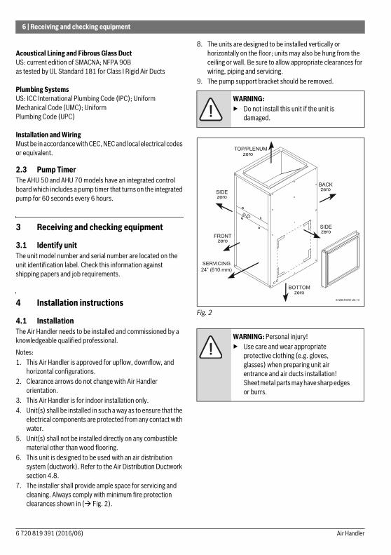
7. The installer shall provide ample space for servicing and cleaning. Always comply with minimum fire protection clearances shown in ( Fig. 2).
8. The units are designed to be installed vertically or horizontally on the floor; units may also be hung from the ceiling or wall. Be sure to allow appropriate clearances for wiring, piping and servicing.
9. The pump support bracket should be removed.
Fig. 2
WARNING: ▶ Do not install this unit if the unit is
damaged.
WARNING: Personal injury!▶ Use care and wear appropriate
protective clothing (e.g. gloves, glasses) when preparing unit air entrance and air ducts installation! Sheet metal parts may have sharp edges or burrs.
6 720 819 391 (2016/06) Air Handler
Installation instructions | 7
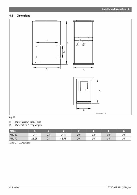
4.2 Dimensions
Fig. 3
[1] Water in via ½ " copper pipe[2] Water out via ½ " copper pipe
Model A B C D E F GAHU 50 17" 23" 35.5" 20" 12" 18" 10"AHU 70 21.25" 23" 43.75" 20" 16" 18" 16"
Table 2 Dimensions
6 720 819 391 (2016/06)Air Handler
8 | Installation instructions
4.3 Locating and mounting the air handler
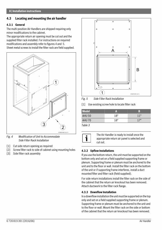
4.3.1 GeneralThe multi-position Air Handlers are shipped requiring only minor modifications to the cabinet. The appropriate return air opening must be cut out and the supplied filter rack installed. For instructions on required modifications and assembly refer to figures 4 and 5.Sheet metal screws to install the filter rack are field supplied.
Fig. 4 Modification of Unit to Accommodate Side Filter Rack Installation
[1] Cut side return opening as required[2] Screw filter rack to side of cabinet using mounting holes[3] Side filter rack assembly
Fig. 5 Side Filter Rack Installation
[1] Use existing screw hole to locate filter rack
4.3.2 Upflow InstallationsIf you use the bottom return, the unit must be supported on the bottom only and set on a field supplied supporting frame or plenum. Supporting frame or plenum must be anchored to the unit and to the floor or wall. Install the filter rack on the bottom of the unit or if supporting frame interferes, install a duct mounted filter and filter rack (field supplied).For side return installations install the filter rack on the side of the cabinet that the return air knockout has been removed. Attach ductwork to the filter rack flange.
4.3.3 Downflow InstallationIn a downflow installation the unit must be supported on the top only and set on a field supplied supporting frame or plenum. Supporting frame or plenum must be anchored to the unit and to the floor or wall. Mount the filter rack on the side or bottom of the cabinet that the return air knockout has been removed.
Model A BAHU 50 18" 11"AHU 70 18" 17"
Table 3
The Air Handler is ready to install once the appropriate return air panel is selected and cut out.
6 720 819 391 (2016/06) Air Handler
Installation instructions | 9
4.3.4 Horizontal Left and Right InstallationsIn a horizontal installation the unit must be supported on the side only and set on a field supplied supporting frame. The
supporting frame must be anchored to the unit and to the floor, wall or ceiling. Mount the filter rack on the side or bottom of the cabinet that the return air knockout has been removed.
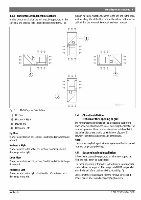
Fig. 6 Multi Purpose Orientation
[1] Up Flow[2] Horizontal Right[3] Down Flow[4] Horizontal Left
Up FlowBlower located below coil section. Conditioned air is discharge upward.
Horizontal RightBlower located to the left of coil section. Conditioned air is discharge to the right.
Down FlowBlower located above coil section. Conditioned air is discharge downward.
Horizontal LeftBlower located to the right of coil section. Conditioned air is discharge to the left.
4.4 Closet installation (return air thru opening or grill)
The Air Handler can be installed in a closet on a supporting stand or be mounted from the closet wall using the closet as the return air plenum. When return air is not ducted directly into the air handler, there should be a minimum of gap of 6" between the filter rack opening and parallel wall.NOTE: Local codes may limit application of systems without a ducted return to single story dwellings.
4.5 Suspend cabinet installationIf the cabinet cannot be supported on a frame or supported from the wall, it may be suspended.Use metal strapping or threaded rod with angle iron supports under cabinet for support. These supports MUST run parallel with the length of the cabinet ( Fig. 6 and Fig. 7).Ensure that there is adequate room to remove service and access panels after installing supporting brackets.
6 720 819 391 (2016/06)Air Handler
10 | Installation instructions
If an auxiliary drain pan is required, the support is to be placed under a drain pan. In such installations, the unit will need to be supported on vibration isolators (rubber or Styrofoam blocks).
IMPORTANT:When a unit is matched with an evaporative type (cased coil/condensing unit) split system for cooling application and the system is installed above a finished ceiling and/or an occupied space, building codes may call for a secondary insulated condensate pan to be installed under the entire unit. In other instances, some local codes may allow the running of a separate, secondary condensate line in lieu of the required drain pan. It is the responsibility of the installer to consult local codes for compliance.
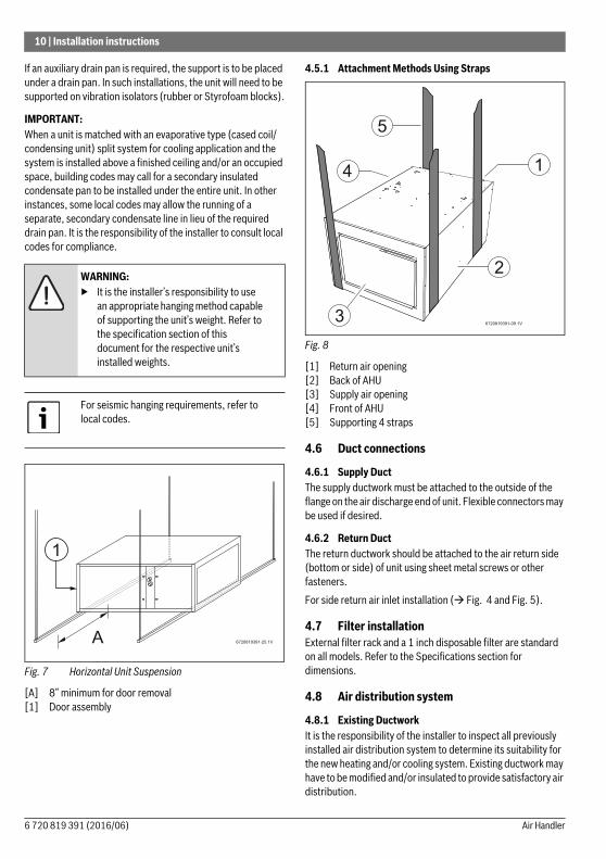
Fig. 7 Horizontal Unit Suspension
[A] 8” minimum for door removal[1] Door assembly
4.5.1 Attachment Methods Using Straps
Fig. 8
[1] Return air opening[2] Back of AHU[3] Supply air opening[4] Front of AHU[5] Supporting 4 straps
4.6 Duct connections
4.6.1 Supply DuctThe supply ductwork must be attached to the outside of the flange on the air discharge end of unit. Flexible connectors may be used if desired.
4.6.2 Return DuctThe return ductwork should be attached to the air return side (bottom or side) of unit using sheet metal screws or other fasteners.For side return air inlet installation ( Fig. 4 and Fig. 5).
4.7 Filter installationExternal filter rack and a 1 inch disposable filter are standard on all models. Refer to the Specifications section for dimensions.
4.8 Air distribution system
4.8.1 Existing DuctworkIt is the responsibility of the installer to inspect all previously installed air distribution system to determine its suitability for the new heating and/or cooling system. Existing ductwork may have to be modified and/or insulated to provide satisfactory air distribution.
WARNING: ▶ It is the installer’s responsibility to use
an appropriate hanging method capable of supporting the unit’s weight. Refer to the specification section of this document for the respective unit’s installed weights.
For seismic hanging requirements, refer to local codes.
6 720 819 391 (2016/06) Air Handler
Installation instructions | 11
4.8.2 Ductwork InstallationConnect the supply-air duct over the outside of 3/4-in. flange on the unit’s discharge side. Secure the duct to the flange with proper fasteners for the type of duct used. Support the duct independently.Use flexible connectors (if desired between the ductwork and the unit to prevent transmission of vibration.Use insulation with vapor barrier for ductwork passing through unconditioned spaces.
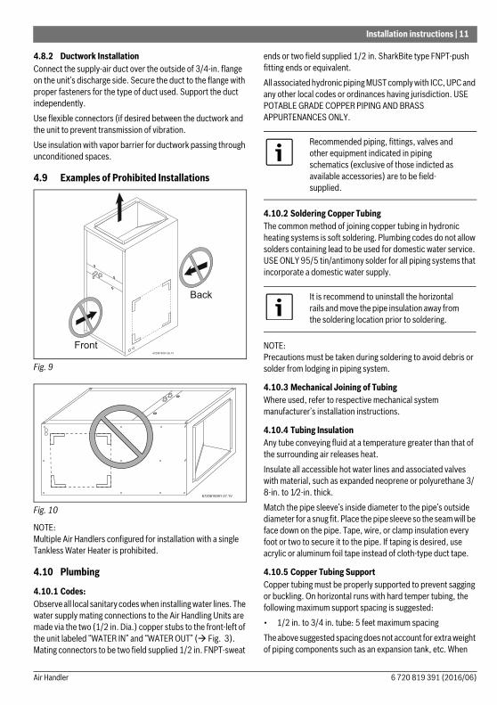
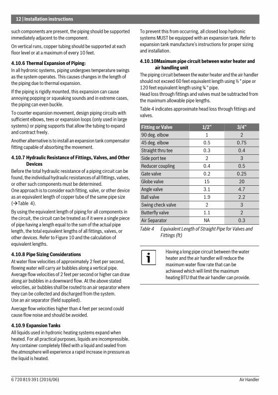
4.9 Examples of Prohibited Installations
Fig. 9
Fig. 10
NOTE: Multiple Air Handlers configured for installation with a single Tankless Water Heater is prohibited.
4.10 Plumbing
4.10.1 Codes:Observe all local sanitary codes when installing water lines. The water supply mating connections to the Air Handling Units are made via the two (1/2 in. Dia.) copper stubs to the front-left of the unit labeled “WATER IN” and “WATER OUT” ( Fig. 3). Mating connectors to be two field supplied 1/2 in. FNPT-sweat
ends or two field supplied 1/2 in. SharkBite type FNPT-push fitting ends or equivalent.All associated hydronic piping MUST comply with ICC, UPC and any other local codes or ordinances having jurisdiction. USE POTABLE GRADE COPPER PIPING AND BRASS APPURTENANCES ONLY.
4.10.2 Soldering Copper TubingThe common method of joining copper tubing in hydronic heating systems is soft soldering. Plumbing codes do not allow solders containing lead to be used for domestic water service. USE ONLY 95/5 tin/antimony solder for all piping systems that incorporate a domestic water supply.
NOTE: Precautions must be taken during soldering to avoid debris or solder from lodging in piping system.
4.10.3 Mechanical Joining of TubingWhere used, refer to respective mechanical system manufacturer’s installation instructions.
4.10.4 Tubing InsulationAny tube conveying fluid at a temperature greater than that of the surrounding air releases heat.Insulate all accessible hot water lines and associated valves with material, such as expanded neoprene or polyurethane 3/8-in. to 1⁄2-in. thick.Match the pipe sleeve’s inside diameter to the pipe’s outside diameter for a snug fit. Place the pipe sleeve so the seam will be face down on the pipe. Tape, wire, or clamp insulation every foot or two to secure it to the pipe. If taping is desired, use acrylic or aluminum foil tape instead of cloth-type duct tape.
4.10.5 Copper Tubing SupportCopper tubing must be properly supported to prevent sagging or buckling. On horizontal runs with hard temper tubing, the following maximum support spacing is suggested:• 1/2 in. to 3/4 in. tube: 5 feet maximum spacingThe above suggested spacing does not account for extra weight of piping components such as an expansion tank, etc. When
Recommended piping, fittings, valves and other equipment indicated in piping schematics (exclusive of those indicted as available accessories) are to be field-supplied.
It is recommend to uninstall the horizontal rails and move the pipe insulation away from the soldering location prior to soldering.
6 720 819 391 (2016/06)Air Handler
12 | Installation instructions
such components are present, the piping should be supported immediately adjacent to the component.On vertical runs, copper tubing should be supported at each floor level or at a maximum of every 10 feet.
4.10.6 Thermal Expansion of Piping:In all hydronic systems, piping undergoes temperature swings as the system operates. This causes changes in the length of the piping due to thermal expansion.If the piping is rigidly mounted, this expansion can cause annoying popping or squeaking sounds and in extreme cases, the piping can even buckle.To counter expansion movement, design piping circuits with sufficient elbows, tees or expansion loops (only used in large systems) or piping supports that allow the tubing to expand and contract freely.Another alternative is to install an expansion tank compensator fitting capable of absorbing the movement.
4.10.7 Hydraulic Resistance of Fittings, Valves, and Other Devices
Before the total hydraulic resistance of a piping circuit can be found, the individual hydraulic resistances of all fittings, valves, or other such components must be determined. One approach is to consider each fitting, valve, or other device as an equivalent length of copper tube of the same pipe size (Table 4).By using the equivalent length of piping for all components in the circuit, the circuit can be treated as if it were a single piece of pipe having a length equal to the sum of the actual pipe length, the total equivalent lengths of all fittings, valves, or other devices. Refer to Figure 10 and the calculation of equivalent lengths.
4.10.8 Pipe Sizing ConsiderationsAt water flow velocities of approximately 2 feet per second, flowing water will carry air bubbles along a vertical pipe. Average flow velocities of 2 feet per second or higher can draw along air bubbles in a downward flow. At the above stated velocities, air bubbles shall be routed to an air separator where they can be collected and discharged from the system. Use an air separator (field supplied).Average flow velocities higher than 4 feet per second could cause flow noise and should be avoided.
4.10.9 Expansion TanksAll liquids used in hydronic heating systems expand when heated. For all practical purposes, liquids are incompressible. Any container completely filled with a liquid and sealed from the atmosphere will experience a rapid increase in pressure as the liquid is heated.
To prevent this from occurring, all closed loop hydronic systems MUST be equipped with an expansion tank. Refer to expansion tank manufacture’s instructions for proper sizing and installation.
4.10.10Maximum pipe circuit between water heater and air handling unit
The piping circuit between the water heater and the air handler should not exceed 60 feet equivalent length using ½ " pipe or 120 feet equivalent length using ¾ " pipe. Head loss through fittings and valves must be subtracted from the maximum allowable pipe lengths.Table 4 indicates approximate head loss through fittings and valves.
Fitting or Valve 1/2” 3/4”90 deg. elbow 1 245 deg. elbow 0.5 0.75Straight thru tee 0.3 0.4Side port tee 2 3Reducer coupling 0.4 0.5Gate valve 0.2 0.25Globe valve 15 20Angle valve 3.1 4.7Ball valve 1.9 2.2Swing check valve 2 3Butterfly valve 1.1 2Air Separator NA 0.3
Table 4 Equivalent Length of Straight Pipe for Valves and Fittings (ft)
Having a long pipe circuit between the water heater and the air handler will reduce the maximum water flow rate that can be achieved which will limit the maximum heating BTU that the air handler can provide.
6 720 819 391 (2016/06) Air Handler
Installation instructions | 13
The piping circuit between the water heater and the air handler should not exceed 60ft equivalent length using ½ " pipe or 120ft equivalent length using ¾ " pipe.
Any piping running through unconditioned space MUST be insulated to prevent heat loss, and possible freezing of the line.
Stickers indicating direction of flow, (WATER IN, and WATER OUT) are labeled on the outside of the cabinet. DO NOT reverse these lines, as this will cause the unit to malfunction.
6 720 819 391 (2016/06)Air Handler
14 | Installation instructions
4.11 Recommended Piping
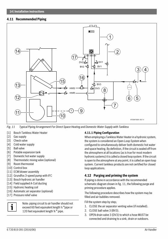
Fig. 11 Typical Piping Arrangement For Direct Space Heating and Domestic Water Supply with Tankless
[1] Bosch Tankless Water Heater[2] Gas supply[3] Check valve[4] Cold water supply[5] Ball valve[6] Potable expansion tank[7] Domestic hot water supply[8] Thermostatic mixing valve (optional)[9] Room thermostat[10] Control box[11] ECM blower assembly[12] Grundfos 3-speed pump with IFC[13] Bosch hydronic air handler[14] Field supplied A-Coil ducting[15] Hydronic heating coil[16] Automatic air separator (optional)[17] Pressure relief valve
4.11.1 Piping ConfigurationWhen employing a Tankless Water Heater in a hydronic system, the system is considered an Open Loop System when configured to simultaneously deliver both domestic hot water and space heating. By definition, if the circuit is sealed off from the atmosphere at all locations (as is true for most modern hydronic systems) it is called a closed loop system. If the circuit is open to the atmosphere at any point, it is called an open loop system. Current tankless products are not certified for closed loop applications.
4.12 Purging and priming the systemIf piping is done in accordance with the recommended schematic diagram shown in fig. 11, the following purge and priming procedure applies.The following procedure describes how the system may be filled and air bubbles removed.Fill the system step by step;1. CLOSE the air separator venting valve (if installed).2. CLOSE ball valve 3 (BV3).3. OPEN drain valve 3 (DV3) to which a hose MUST be
connected and draining to a sink, drain or outdoors.
15
109
7
4
2
1
11
12
13
14
6
16
8
3
17
6720819391-06.1V
5
Note: piping circuit to air handler should not exceed 60 feet equivalent length ½ "pipe or 120 feet equivalent length ¾ " pipe.
6 720 819 391 (2016/06) Air Handler
Installation instructions | 15
4. CLOSE drain valves 1 and 2 (DV1 and DV2) and OPEN ball valve 2 (BV2).
5. OPEN cold water supply main valve (ball valve 1 - BV1). The system will begin the prime/purge process using the street pressure. Entrapped air bubbles being pushed out of the system will be evident by a slight vibration of the discharge hose connected to drain valve 3 (DV3). The hose will stop vibrating when the air has been removed from the system.
6. CLOSE drain valve 3 (DV3).7. OPEN ball valve 3 (BV3). The system is now purged,
primed and ready to go.8. OPEN the air separator venting valve (if installed).
4.13 Electrical connections
Line-Voltage ConnectionsMake all electrical connections in accordance with Canadian Electrical Code CSA C22.1 and all authorities having jurisdiction.Check all factory wiring per unit wiring diagram and inspect factory wiring connections to be sure none were loosened in transit.
NOTE: Prior to making any electrical connections, ensure that supply voltage, frequency, and phase are as specified on unit rating plate.Check to ensure that the existing electrical service is adequate to handle the additional load imposed by the Air Handler. Refer to unit wiring diagram for proper electrical connections.
All electrical connections MUST comply with NEC and any other local codes or ordinances having jurisdiction. USE COPPER WIRE ONLY. Provide separate branch electric circuit with field supplied disconnect switch.Location of disconnect switch to be in clear site, accessible and in close proximity to the unit. Correct polarity MUST be maintained for 115 V wiring. If polarity is incorrect unit will NOT operate.
Electrical Connection to Control Box1. Route the Air Handler power wires through aligned holes in
casing and Control Box and make field wire connections in Control Box. Use best practices for wire bushings, strain relief, etc. Field wiring to the unit must be grounded and conform to the National Electrical Code C22.1 Part 1 - latest edition. Use only CSA or UL listed conduit and conduit connectors to connect supply wires to the unit and provide appropriate grounding. Grounding may also be accomplished by grounding the control box per appropriate local codes. Electric wires that are field installed shall conform to the temperature limitation for 63° F (35° C) rise wire when installed in accordance with instructions. Refer to Table 3 in for specific Air Handler electrical data.
2. Route and secure field ground wire to ground screw on Control Box.
3. Connect line voltage leads ( Fig. 12).4. Reinstall cover to Control Box. Ensure that wires are not
pinched between cover and edge of Control Box.
24V Control System Connections to Unit’s Printed-Circuit Board (PCB):Refer to Figure 12 for factory wiring details. For low voltage connections between the unit and the thermostat, use No. 18 AWG color-coded, insulated (63° F / 35°C minimum) wires.
Low Voltage ConnectionsThese units use a grounded 24 volt AC low voltage circuit and require at least a 1 stage heating and a 1 stage cooling thermostat.The “R” terminal is the hot terminal and the “C” terminal is grounded.“G” terminal is the call for low speed fan only mode.“Y” terminal is the call for cooling.
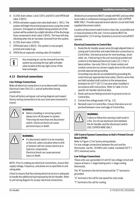
Any remaining air can be removed from the system by pressing the top right schrader valve located at the top right corner of the heat exchanger.
WARNING: ▶ Before installing or servicing system,
always turn off all power to system. There may be more than one disconnect switch. Electrical shock can cause personal injury or death.
WARNING: ▶ If a disconnect switch is to be mounted
on the unit, select a location where a drill or fastener will not contact electrical or hydronic components. Electrical shock can cause personal injury or death.
WARNING: Failure to follow this warning could result in a fire. Do not use aluminum wire between the Air Handler and the disconnect switch. USE COPPER WIRE ONLY.
6 720 819 391 (2016/06)Air Handler
16 | Installation instructions
“R” terminal is 24 VAC hot.“C” terminal is 24 VAC grounded.“W” terminal is the call for heat.
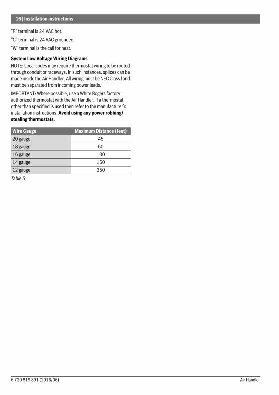
System Low Voltage Wiring DiagramsNOTE: Local codes may require thermostat wiring to be routed through conduit or raceways. In such instances, splices can be made inside the Air Handler. All wiring must be NEC Class l and must be separated from incoming power leads.IMPORTANT: Where possible, use a White Rogers factory authorized thermostat with the Air Handler. If a thermostat other than specified is used then refer to the manufacturer’s installation instructions. Avoid using any power robbing/ stealing thermostats.
Wire Gauge Maximum Distance (feet)20 gauge 4518 gauge 6016 gauge 10014 gauge 16012 gauge 250
Table 5
6 720 819 391 (2016/06) Air Handler
Installation instructions | 17
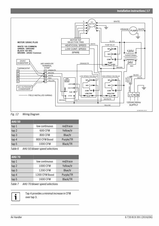
Fig. 12 Wiring Diagram
AHU 50tap 1 low continuous red/tracetap 2 600 CFM Yellow/trtap 3 800 CFM Blue/trtap 4 800 CFM Boost Purple/TRtap 5 1000 CFM Black/TR
Table 6 AHU 50 blower speed selections
AHU 70tap 1 low continuous red/tracetap 2 1000 CFM Yellow/trtap 3 1200 CFM Blue/trtap 4 1200 CFM Boost Purple/TRtap 5 1600 CFM Black/TR
Table 7 AHU 70 blower speed selections
Tap 4 provides a minimal increase in CFM over tap 3.
6 720 819 391 (2016/06)Air Handler
18 | Installation instructions
4.14 Selecting fan speedsBlower motor torque settings are selected by moving the wires on the motor tap selection tree located in the blower mounted electrical box.▶ Use the Blower Motor Wire Selection Chart in this manual
to select the proper wires for your application.
Fig. 13
4.14.1 Heat / Cool fan speed▶ Select the appropriate motor tap wire to plug into this
terminal.This is the speed the motor will run for both heating and cooling.
4.14.2 Low continuous fan▶ Select the appropriate motor tap wire to plug into this
terminal.This is the speed the motor will run when the thermostat Fan switch is set to the ON position.
4.14.3 Spare▶ Plug any unused motor tap wires onto this terminal.
Blower motor wire selection chart
Example:Model AHU 50Blue/Trace wire onto the heat / cool fan speed Terminal Unit will run at 800 cfm for both heating and cooling (@0.4” external static)
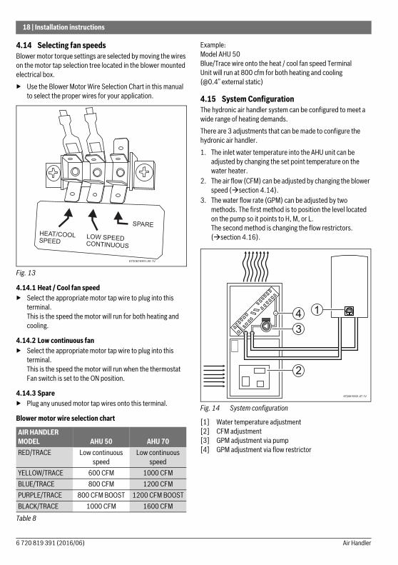
4.15 System ConfigurationThe hydronic air handler system can be configured to meet a wide range of heating demands.There are 3 adjustments that can be made to configure the hydronic air handler.1. The inlet water temperature into the AHU unit can be
adjusted by changing the set point temperature on the water heater.
2. The air flow (CFM) can be adjusted by changing the blower speed (section 4.14).
3. The water flow rate (GPM) can be adjusted by two methods. The first method is to position the level located on the pump so it points to H, M, or L.The second method is changing the flow restrictors. (section 4.16).
Fig. 14 System configuration
[1] Water temperature adjustment[2] CFM adjustment[3] GPM adjustment via pump[4] GPM adjustment via flow restrictor
AIR HANDLER MODEL AHU 50 AHU 70RED/TRACE Low continuous
speedLow continuous
speedYELLOW/TRACE 600 CFM 1000 CFMBLUE/TRACE 800 CFM 1200 CFMPURPLE/TRACE 800 CFM BOOST 1200 CFM BOOSTBLACK/TRACE 1000 CFM 1600 CFM
Table 8
4
2
1
6720819391-07.1V
3
6 720 819 391 (2016/06) Air Handler

Installation instructions | 19
4.15.1 Performance chartsThe following tables are performance charts for the AHU 50 and AHU 70 models. After the heating load requirements have
been determined for the home, the performance tables can be used to choose the optimum system configuration.
AHU 50 OUTPUT @ 70 °F RETURN AIR TEMP120 °F inlet water
temp130 °F inlet water
temp140 °F inlet water
temp160 °F inlet water
temp
Air F
low
(CFM
)
Wat
er Fl
ow (G
PM)
Wat
er P
ress
. Dro
p(F
T Hea
d)
Outp
ut (B
TU)
Exiti
ng A
ir (°
F)
Exiti
ng W
ater
(°F
)
Outp
ut (B
TU)
Exiti
ng A
ir (°
F)
Exiti
ng W
ater
(°F
)
Outp
ut (B
TU)
Exiti
ng A
ir (°
F)
Exiti
ng W
ater
(°F
)
Outp
ut (B
TU)
Exiti
ng A
ir (°
F)
Exiti
ng W
ater
(°F
)
600 123
0.712.515.27
172002380025800
96.5106.7109.8
85.696.2
102.8
219002860031000
103.8114.1117.8
86.2101.4109.3
256003350036300
109.5121.7126.0
88.8106.5115.8
331004330046800
121.1136.8142.2
93.8116.7128.8
800 123
0.712.525.28
196002800031500
92.7102.4106.5
80.892.099.0
239003380037900
97.7109.1113.9
82.296.2
104.7
279003950044300
102.3115.7121.3
84.2100.5110.5
361005110057200
111.8129.1136.2
87.8108.9121.9
1000 123
0.722.535.29
196003120036000
88.198.9
103.3
80.888.896.0
243003750043400
92.5104.7110.2
81.492.5
101.1
288004390050700
96.7110.6116.9
82.496.1
106.2
379005680065600
105.1122.6130.7
84.2103.2116.2
Table 9 Bosch AHU 50
AHU 70 OUTPUT @ 70 °F RETURN AIR TEMP120 °F inlet water
temp130 °F inlet water
temp140 °F inlet water
temp160 °F inlet water
temp
Air F
low
(CFM
)
Wat
er Fl
ow (G
PM)
Wat
er P
ress
. Dro
p(F
T Hea
d)
Outp
ut (B
TU)
Exiti
ng A
ir (°
F)
Exiti
ng W
ater
(°F
)
Outp
ut (B
TU)
Exiti
ng A
ir (°
F)
Exiti
ng W
ater
(°F
)
Outp
ut (B
TU)
Exiti
ng A
ir (°
F)
Exiti
ng W
ater
(°F
)
Outp
ut (B
TU)
Exiti
ng A
ir (°
F)
Exiti
ng W
ater
(°F
)1000 2
34
1.382.985.10
303003520037900
98.1102.6105.1
89.796.5
101.0
385004240045600
105.6109.3112.2
91.5101.7107.2
428004970053300
109.6116.0119.4
97.2106.9113.3
553006420068900
121.2129.4133.8
104.7117.2125.5
1200 234
1.382.985.10
326003890042500
95.2100.0102.8
87.494.198.7
414004680051100
101.6106.1109.4
88.698.8
104.4
460005480059800
105.5112.3116.1
94.0103.5110.1
595007090077300
115.9124.7129.6
100.5112.7121.3
1600 234
1.382.985.10
357004430049700
90.795.698.8
84.390.595.1
453005340059900
96.2100.9104.7
84.794.4
100.0
503006250070100
99.1106.2110.6
89.798.3
104.9
650008090090700
107.6116.8122.5
95.0106.0114.6
Table 10 Bosch AHU 70
6 720 819 391 (2016/06)Air Handler

20 | Installation instructions
4.16 Changing flow restrictors
Turn off the supply and return isolation valves. Using a socket wrench, remove the angled side port fitting. Extract the Polymer diaphragm and the Polyphenylsulfone orifice. Place the new O’ring in the end groove of the orifice and insert into the cavity. Replace the O’ring on the side port fitting. Install the polymeric diaphragm into the orifice, and the side port fitting into the angled cavity. Torque the side port fitting to 50-80 In Lbs (4.2-6.7 Ft Lbs) using a ¾ " socket wrench. Turn on the supply and return valves and check for leaks.
4.17 Thermostat installation
Safety ConsiderationsAll wiring must conform to local and national electrical codes. Improper wiring or installation may damage thermostat.
Air Conditioner ModelSee fig. 12 for wiring details. The Standard Model A/C thermostat may be wired with or without connecting a common wire between the indoor equipment and the thermostat. However, it is recommended to use a common wire whenever possible. Do not use a power-stealing thermostat. If an evaporating coil is installed above the hot water coil, then a
Freeze stat must be installed to prevent potential freeze damage to the hot water coil and subsequent waster escape.
InstallationThermostat should be mounted:• approximately 5 ft. (1.5 m) from floor;• close to or in a frequently used room, preferably on an
inside partitioning wall;• on a section of wall without pipes or ductwork.Thermostat should NOT be mounted:• close to a window, on an outside wall, or next to a door
leading to the outside;• exposed to direct light and heat from a lamp, sun, fireplace,
or other heat-radiating object which may cause a false reading;
• close to or in direct airflow from supply registers and return-air grills;
• in areas with poor air circulation, such as behind a door or in an alcove.
For thermostat wiring diagram (See Fig. 12).
4.18 Installation considerationsWhen domestic hot water is requested while the thermostat is calling for heat, the air leaving the air handler may decrease in temperature. The air handler will continue to operate while domestic water is being used. When the request for domestic hot water is finished the temperature of the exit air will automatically increase to the normal operating level.Below are steps that can be taken to minimize the affect that domestic hot water has on the air handler performance. A smart thermostat can be programmed to call for heat 1 hour before peak domestic hot water use is expected. The set point temperature of the water heater can be increased.
4.19 Start-up procedureThe following conditions must be met prior to unit start-up.Debris from soldering and/or other installation activities can cause equipment failure. Ensure that all associated lines and appurtenances are free of debris.▶ Check to ensure that unit is secure.▶ Check that blower wheel rotates freely within the scroll
housing.▶ Check all wiring to ensure that connections are tight.▶ Check all ductwork and pipe connections to ensure proper
seal.▶ Check to ensure that all packaging wraps are removed from
equipment.▶ Ensure that front access doors are properly installed.
WARNING: Severe burns!▶ For water temperatures above 120F, a
thermostatic valve should be installed on the domestic water line.
Flow rate may be limited by pressure drop across piping from water heater to air handling Unit.
Inlet water temperature may be limited by water heater capacity and temperature of cold domestic water.
Water flow rate may be adjusted by changing the polymer diaphragm.
WARNING: ▶ Before installing thermostat, turn off all
power to unit. There may be more than one power disconnect. Electrical shock can cause personal injury or death.
6 720 819 391 (2016/06) Air Handler

Sequence of operation | 21
▶ Check to ensure proper connection(s) to the appropriate blower speed tap. To select the correct model and desired fan speed data ( table 11, page 27). Refer to ( Fig. 12) for appropriate motor tap/wire colour to use.
▶ Perform all safety and start-up checks for Tankless Water Heater as per manufacturer’s instructions.
Having verified all preceding checks, the Air Handler’s Start-Up Procedure is as follows, step by step:1. Purge and fill system; follow appropriate purging
procedure as laid out in this manual in section titled “Purging and Priming the System”.
2. Turn on power supply to Air Handler.
1. Turn thermostat on and switch system to the heating mode. The thermostat shall be set higher than the actual room temperature; this will cause the circulator to energize and initiate the heating cycle. (If the pump does not start, or the Air Handler is not producing heat, refer to the Troubleshooting Section in this manual).
2. Program room thermostat as desired by homeowner.
4.20 Start-up procedure (cooling system)Refer to field supplied evaporator coil and outdoor unit manufacturer’s Installation Instructions for system hook-up, start-up instructions and refrigerant charging method details.
4.21 Troubleshooting blower and/or pump motor and controls
▶ Check all connections for kinks which could cause loose connections. Ensure connections are secure.
▶ Verify that approximately 120 VAC is present across L1 and L2.
5 Sequence of operation
5.1 Standby modeAll control outputs are off and the control is waiting for a thermostat demand. The control initiates action when a thermostat call is received.
5.2 Cooling mode
Air-Conditioning (A/C) Cooling DemandWhen the thermostat calls for cooling (Y), the control energizes the selected heat/cool blower speed.
5.3 Heating mode
Heat DemandWhen the thermostat calls for heat (W), the control board energizes the pump, allows the heat exchanger to preheat for 30 seconds, then energizes the blower at the selected heat/cool speed.When the thermostat stops calling for heat (W), the control board dienergizes the pump and keeps the blower ON for 30 additional seconds to extract the heat remaining in the heat exchanger.
Off Season Circulation TimerThe AHU 50 and AHU 70 models have an integrated control board which includes a pump timer that turns on the integrated pump for 60 seconds every 6 hours.
CAUTION: ▶ Blower and/or circulator may start to
operate if thermostat is on and a call is present.
CAUTION: High voltage is at all times present at motor.▶ Disconnect power to AHU before
removing, or replacing, or servicing motor. Wait at least 5 min after disconnecting power before opening motor. Failure to follow this CAUTION could result in minor personal injury or product and property damage.
6 720 819 391 (2016/06)Air Handler
22 | Troubleshooting
6 Troubleshooting
6.1 Most likely problems and causes
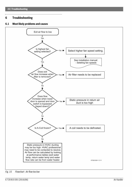
Fig. 15 Flowchart - Air flow too low
Exit air flow to low
Static pressure in HVAC ductingmay be too high. HVAC professionalmay need to be contacted to resolve.Air flow can be calculated by looking
at performance tables (exit watertemp, return water temp and waterflow rate can be from water heater.
Yes
NoIs highest fan
setting selected?
Yes
Yes
Does exitair flow increase when
filter is removed?
No
Yes
Does flowincrease when lower
door is opened and doorswitch is bypassed
(taped down)?
No
YesIs A-Coil frozen?
No
Select higher fan speed setting.
Air filter needs to be replaced
Static pressure in return airduct is too high
A coil needs to be defrosted.
6720819391-12.1V
See installation manual:- Seleting fan speeds
6 720 819 391 (2016/06) Air Handler
Troubleshooting | 23
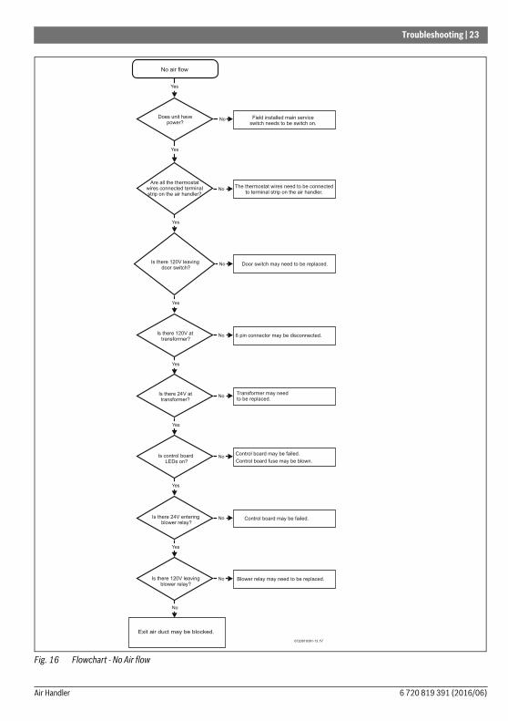
Fig. 16 Flowchart - No Air flow
No air flow
Yes
NoDoes unit have
power?
Yes
No
Yes
No
Yes
No
Door switch may need to be replaced.
Yes
Field installed main serviceswitch needs to be switch on.
6 pin connector may be disconnected.
NoIs there 24V attransformer?
Yes
Transformer may needto be replaced.
NoIs control boardLEDs on?
Yes
6720819391-13.1V
NoIs there 24V enteringblower relay?
Yes
NoIs there 120V leavingblower relay?
No
Blower relay may need to be replaced.
Are all the thermostatwires connected terminalstrip on the air handler?
The thermostat wires need to be connectedto terminal strip on the air handler.
Is there 120V leavingdoor switch?
Is there 120V attransformer?
Control board fuse may be blown.
Control board may be failed.
Exit air duct may be blocked.
Control board may be failed.
6 720 819 391 (2016/06)Air Handler
24 | Troubleshooting
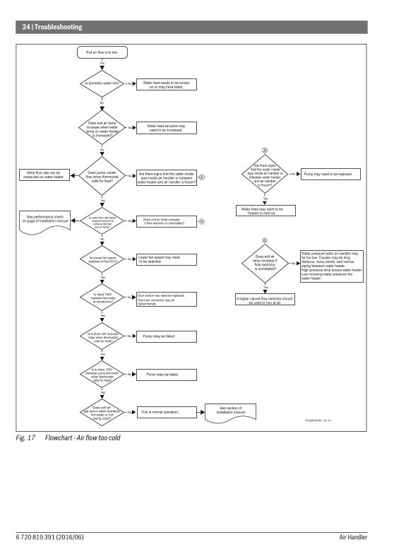
Fig. 17 Flowchart - Air flow too cold
6720819391-14.1V
Exit air flow is to low
Yes
NoIs domestic water hot?
No
Yes
No
Yes
Yes
No
Water heat needs to be turnedon or may have failed.
NoAre there signs that the water inside
pipe inside air handler or betweenwater heater and air handler is frozon?
Does exit air temp increaseif flow restrictor is uninstalled?
Iis lowest fan speedselected on fan ECU?
Yes
NoLower fan speed may needto be selected.
NoIs there 120V
between terminalsat transformer?
Yes
NoIs Is there 24V at pumprelay when thermostat
calls for heat?
Yes
No
Is Is there 120Vbetween pump terminals
when thermostatcalls for heat?
Yes
Pump relay be failed.
Does exit air tempincrease when watertemp on water heater
is increased?
Water heat set point mayneed to be increased.
Does pump createflow when thermostat
calls for heat?
Iis water flow rate belowrequired amount toachieve desiredexit air temp?
Top 6 pin connector may bedisconnected.
Pump relay be failed.
Does exit airget warm when domestic
hot water is notbeing used?
Door switch may need be replaced..
What flow rate can bemeasured on water heater
See performance chartson page of installation manual.
Yes This is normal operation.See section of
installation manual.
Water lines may need to beheated to melt ice.
Yes
Pump may need to be replaced.NoNo
Are there signsthat the water inside
pipe inside air handler orbetween water heater
and air handleris frozon?
Water pressure befor air handler maybe too low. Causes may be longdistance, many bends, and narrowpiping between water heater.High pressure drop across water heater.Low incoming water pressure intowater heater.
A higher valued flow restrictor shouldbe used or non at all.
Yes
Does exit airtemp increase if
flow restrictoris uninstalled?
NoNo
6 720 819 391 (2016/06) Air Handler

Troubleshooting | 25
Fig. 18 Flowchart - Thermostat does not run
Thermostat does not turn on
Yes
Yes
Is there 24VAC across"R" and "C" terminals on
terminal strip in air handler?
No
Yes
No
Thermostat may need to be replaced
Yes Transformer may need to be replaced..
6720819391-15.1V
Is there 24VAC acrosstransformer output terminals?
"R" and "C" may be damaged betweentranformer and thermostat.
Is there 120VAC acrosstransformer input terminals?
No
No
Yes
6 pin connector should be plugged in.
NoIs there 120VAC entering
the air handler's junction box?
Yes
Outside switch may need to be replaced.
Is 6 pin connector completelyplugged in?
120VAC electrical connection at junctionbox needs to be repaired.
Home's fuse my be tripped.
6 720 819 391 (2016/06)Air Handler
26 | Maintenance
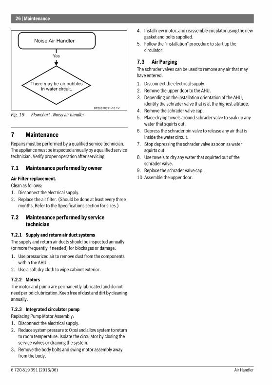
Fig. 19 Flowchart - Noisy air handler
7 MaintenanceRepairs must be performed by a qualified service technician. The appliance must be inspected annually by a qualified service technician. Verify proper operation after servicing.
7.1 Maintenance performed by owner
Air Filter replacement.Clean as follows:1. Disconnect the electrical supply.2. Replace the air filter. (Should be done at least every three
months. Refer to the Specifications section for sizes.)
7.2 Maintenance performed by service technician
7.2.1 Supply and return air duct systemsThe supply and return air ducts should be inspected annually (or more frequently if needed) for blockages or damage.1. Use pressurized air to remove dust from the components
within the AHU.2. Use a soft dry cloth to wipe cabinet exterior.
7.2.2 MotorsThe motor and pump are permanently lubricated and do not need periodic lubrication. Keep free of dust and dirt by cleaning annually.
7.2.3 Integrated circulator pumpReplacing Pump Motor Assembly:1. Disconnect the electrical supply.2. Reduce system pressure to 0 psi and allow system to return
to room temperature. Isolate the circulator by closing the service valves or draining the system.
3. Remove the body bolts and swing motor assembly away from the body.
4. Install new motor, and reassemble circulator using the new gasket and bolts supplied.
5. Follow the “installation” procedure to start up the circulator.
7.3 Air PurgingThe schrader valves can be used to remove any air that may have entered.1. Disconnect the electrical supply.2. Remove the upper door to the AHU.3. Depending on the installation orientation of the AHU,
identify the schrader valve that is at the highest altitude.4. Remove the schrader valve cap.5. Place drying towels around schrader valve to soak up any
water that squirts out.6. Depress the schrader pin valve to release any air that is
inside the water circuit.7. Stop depressing the schrader valve as soon as water
squirts out.8. Use towels to dry any water that squirted out of the
schrader valve.9. Replace the schrader valve cap.10. Assemble the upper door.
Noise Air Handler
Yes
There may be air bubblesin water circuit.
6720819391-16.1V
6 720 819 391 (2016/06) Air Handler
Air Handler Specifications | 27
8 Air Handler Specifications
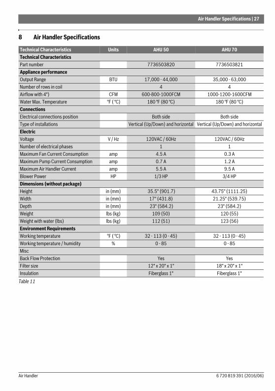
Technical Characteristics Units AHU 50 AHU 70Technical CharacteristicsPart number 7736503820 7736503821Appliance performanceOutput Range BTU 17,000 - 44,000 35,000 - 63,000Number of rows in coil 4 4Airflow with 4") CFM 600-800-1000FCM 1000-1200-1600CFMWater Max. Temperature °F ( °C) 180 °F (80 °C) 180 °F (80 °C)ConnectionsElectrical connections position Both side Both sideType of installations Vertical (Up/Down) and horizontal Vertical (Up/Down) and horizontalElectricVoltage V / Hz 120VAC / 60Hz 120VAC / 60HzNumber of electrical phases 1 1Maximum Fan Current Consumption amp 4.5 A 0.3 AMaximum Pump Current Consumption amp 0.7 A 1.2 AMaximum Air Handler Current amp 5.5 A 9.5 ABlower Power HP 1/3 HP 3/4 HPDimensions (without package)Height in (mm) 35.5" (901.7) 43.75" (1111.25) Width in (mm) 17" (431.8) 21.25" (539.75) Depth in (mm) 23" (584.2) 23" (584.2)Weight lbs (kg) 109 (50) 120 (55)Weight with water (lbs) lbs (kg) 112 (51) 123 (56)Environment RequirementsWorking temperature °F ( °C) 32 - 113 (0 - 45) 32 - 113 (0 - 45)Working temperature / humidity % 0 - 85 0 - 85MiscBack Flow Protection Yes YesFilter size 12" x 20" x 1" 18" x 20" x 1"Insulation Fiberglass 1" Fiberglass 1"
Table 11
6 720 819 391 (2016/06)Air Handler
28 | Accessories
9 Accessories
9.1 Field supplied accessories
1. Anti-scald Thermostatic Temperature Control ValveAnti-scald thermostatic temperature control valves are an important part of domestic water plumbing because they eliminate the scalding and cold water shocks that can occur in a shower when a toilet is flushed or a faucet is turned on. In an Open Loop system (dual function – space heating and domestic water heating), an anti-scald valve should be installed when the Tankless Water heater set thermostat is above 120°F (49°C); refer to local codes and/or all authority having jurisdiction. For recommended piping configuration, refer to Figure 11. Anti-Scald valve shall be thermostatically controlled and meet at least the following specifications:• Dual certification ASSE 1016-T and ASSE 1017• IAPMO Approved• CSA Approved
2. Expansion Tank
3. Air Separator
4. Anti-ice sensor for Installations with Air Conditioning
6 720 819 391 (2016/06) Air Handler
Part List | 29
10 Part List
10.1 Replacement Parts List
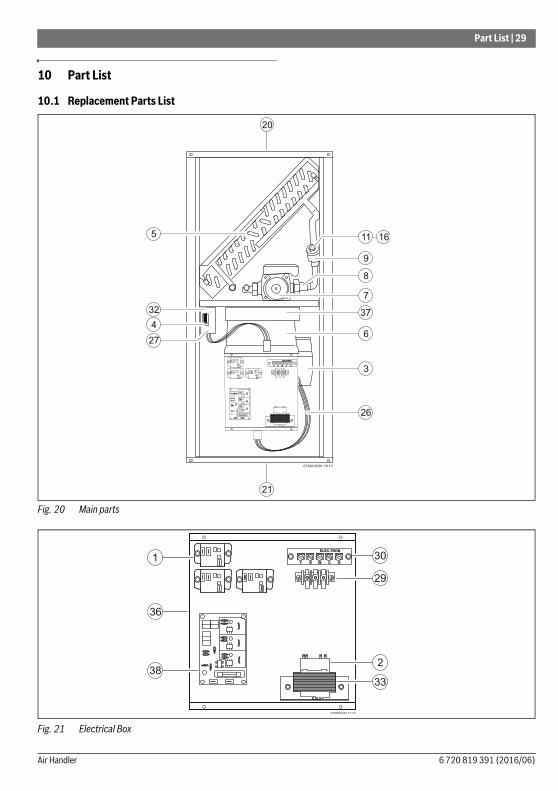
Fig. 20 Main parts
Fig. 21 Electrical Box
Y R W C G
ELEC-TRON
5
32
4
27
26
3
6
37
7
8
9
11
21
20
6720819391-18.1V
16
Y R W C G
ELEC-TRON
30
29
2
3338
1
36
6720819391-17.1V
6 720 819 391 (2016/06)Air Handler

30 | Part List
Bosch AHU50 AHU 70Item Part Description Part number 7736503820 77365038211 Relay 8 738 714 389 h h
2 Transformer 8 738 714 390 h h
3 Motor 8 738 714 391 h
3 Motor 8 738 714 392 h
4 Door Switch 8 738 714 393 h h
5 Heating Coil 8 738 714 394 h
5 Heating Coil 8 738 714 395 h
6 Blower Housing 8 738 714 396 h
6 Blower Housing 8 738 714 397 h
7 Pump 8 738 714 398 h
7 Pump 8 738 714 399 h
8 Check Valve (for Pump) 8 738 714 402 h h
9 Flow Valve Body 8 738 714 387 h h
10 Flow Valve Kit 8 738 714 388 h h
11 Flow Valve 1.0 GPM 8 738 714 403 h h
12 Flow Valve 1.5 GPM 8 738 714 404 h h
13 Flow Valve 2.0 GPM 8 738 714 405 h h
14 Flow Valve 2.5 GPM 8 738 714 406 h h
15 Flow Valve 3.0 GPM 8 738 714 407 h h
16 Flow Valve 4.0 GPM 8 738 714 408 h h
17 Filter Rack for 12" x 20" 8 738 714 409 h
17 Filter Rack for 18" x 20" 8 738 714 410 h
18 Upper door, including insulation and foam strip 8 738 714 411 h
18 Upper door, including insulation and foam strip 8 738 714 412 h
19 Lower door, including insulation and foam strip and door switch plate 8 738 714 413 h
19 Lower door, including insulation and foam strip and door switch plate 8 738 714 414 h
20 Top, with insulation 8 738 714 417 h
20 Top, with insulation 8 738 714 418 h
21 Bottom, with insulation 8 738 714 419 h
21 Bottom, with insulation 8 738 714 420 h
22 Filter rack cover panel 8 738 714 421 h
22 Filter rack cover panel 8 738 714 422 h
23 Misc hardware kit 8 738 714 423 h h
24 Upper rail, with insulation and input/output label 8 738 714 424 h
25 Lower rail 8 738 714 425 h
24 Upper rail, with insulation and input/output label 8 738 714 426 h
25 Lower rail 8 738 714 427 h
26 Wiring, blower with connectors 8 738 714 429 h h
27 Cube, Wiring, House power and pump with connectors, junction box with door switch, cover
8 738 714 430 h
27 Cube, Wiring, House power and pump with connectors, junction box with door switch, cover
8 738 714 431 h
28 Internal wire harness 8 738 714 432 h h
Table 12 Part list
6 720 819 391 (2016/06) Air Handler

Part List | 31
[i] Wiring diagram located on page 16
29 Terminal block, fan selection 8 738 714 433 h h
30 24V HVAC terminal strip 8 738 714 434 h h
31 Plumbing kit including, pump fittings, check valve, flow valve body and copper pipe
8 738 714 435 h
31 Plumbing kit including, pump fittings, check valve, flow valve body and copper pipe
8 738 714 436 h
32 Cover, connection box for house power 8 738 714 437 h h
33 Transformer bracket 8 738 714 438 h h
34 Motor bracket 8 738 714 439 h h
35 bracket, blower 8 738 714 440 h
35 bracket, blower 8 738 714 441 h
36 Blower mounted electrical box (complete with all internal components and cover)
8 738 714 442 h
37 Cover for blower mounted electrical box 8 738 714 443 h
36 Blower mounted electrical box (complete with all internal components and cover)
8 738 714 444 h
37 Cover for blower mounted electrical box 8 738 714 445 h
38 Control board - P9-11 Capable -DVS Stye - controls LSF, HSF, Pump 8 738 714 448 h h
Bosch AHU50 AHU 70Item Part Description Part number 7736503820 7736503821
Table 12 Part list
6 720 819 391 (2016/06)Air Handler

Bosch Thermotechnology Corp.
50 Wentworth Avenue
Londonderry, NH 03053
U.S.A.
Bosch Thermotechnology Corp. reserves the right
to make changes without notice due to continuing
engineering and technological advances.
Tel. 603-552-1100
Fax 603-965-7581
www.boschheatingandcooling.com