Embed Size (px)
DESCRIPTION
AIA National CAD Standards Chapter 5 02-Layers Guideline Virtually all vector-based CAD systems support the concept of layers. This function allows building designinformation to be organized in a systematic fashion, facilitates the visual display of the information on acomputer screen, and allows the information to be efficiently converted to the conventional print media ofdrawings. Efficient use of layers can reduce document preparation time and improve document coordination.Organizing data by layers allows a single CAD file to contain a wealth of information about a building or facility.By turning selected layers on or off, data can be created, reviewed and edited according to a hierarchy thatsimulates the physical organization of building systems, the relative position of building elements, or thesequence of construction.
Citation preview
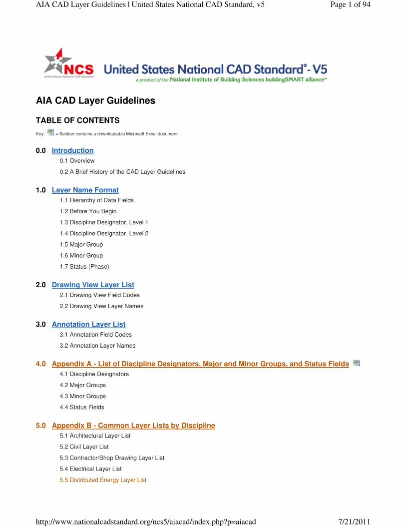
Key: = Section contains a downloadable Microsoft Excel document
0.0 Introduction
0.1 Overview
0.2 A Brief History of the CAD Layer Guidelines
1.0 Layer Name Format
1.1 Hierarchy of Data Fields
1.2 Before You Begin
1.3 Discipline Designator, Level 1
1.4 Discipline Designator, Level 2
1.5 Major Group
1.6 Minor Group
1.7 Status (Phase)
2.0 Drawing View Layer List
2.1 Drawing View Field Codes
2.2 Drawing View Layer Names
3.0 Annotation Layer List
3.1 Annotation Field Codes
3.2 Annotation Layer Names
4.0 Appendix A - List of Discipline Designators, Major and Minor Groups, and Status Fields
4.1 Discipline Designators
4.2 Major Groups
4.3 Minor Groups
4.4 Status Fields
5.0 Appendix B - Common Layer Lists by Discipline
5.1 Architectural Layer List
5.2 Civil Layer List
5.3 Contractor/Shop Drawing Layer List
5.4 Electrical Layer List
5.5 Distributed Energy Layer List
AIA CAD Layer Guidelines
TABLE OF CONTENTS
Page 1 of 94AIA CAD Layer Guidelines | United States National CAD Standard, v5
7/21/2011http://www.nationalcadstandard.org/ncs5/aiacad/index.php?p=aiacad
5.6 Equipment Layer List
5.7 Fire Protection Layer List
5.8 General Layer List
5.9 Geotechnical Layer List
5.10 Hazardous Materials Layer List
5.11 Interiors Layer List
5.12 Landscape Layer List
5.13 Mechanical Layer List
5.14 Operations Layer List
5.15 Plumbing Layer List
5.16 Process Layer List
5.17 Resource Layer List
5.18 Structural Layer List
5.19 Survey/Mapping Layer List
5.20 Telecommunications Layer List
5.21 Other Disciplines Layer List
6.0 Appendix C - Complying with NCS and ISO 13567
6.1 Overview
6.2 Field Codes
6.3 Field Codes and Language
6.4 ISO 13567 Conformance
6.5 Field Names and Definitions
6.6 "Discipline Designator" vs. "Agent Responsible"
6.7 "Agent Responsible" and Professional Liability
6.8 "Discipline Designator" and the Building Life Cycle
6.9 "Discipline Designator" and ISO 13567 Conformance
6.10 Field Code Restrictions
6.11 NCS and ISO 13567 Implementation Options
6.12 NCS and ISO 13567 Implementation Guidelines
Virtually all vector-based CAD systems support the concept of layers. This function allows building design
information to be organized in a systematic fashion, facilitates the visual display of the information on a
computer screen, and allows the information to be efficiently converted to the conventional print media of
drawings. Efficient use of layers can reduce document preparation time and improve document coordination.
Organizing data by layers allows a single CAD file to contain a wealth of information about a building or facility.
By turning selected layers on or off, data can be created, reviewed and edited according to a hierarchy that
simulates the physical organization of building systems, the relative position of building elements, or the
sequence of construction.
0.0 Introduction
0.1 OVERVIEW
Page 2 of 94AIA CAD Layer Guidelines | United States National CAD Standard, v5
7/21/2011http://www.nationalcadstandard.org/ncs5/aiacad/index.php?p=aiacad
The American Institute of Architects (AIA) published the first edition of CAD Layer Guidelines in 1990. The early
success of the first edition and rapidly evolving technology resulted in the second edition being published in
1997. The most significant change between the first and second editions was the elimination of the "short" layer
name format and the adoption of the long layer name format as a single standard. The second edition also
included additional layer field codes for remodeling projects, added new discipline designations for interiors,
telecommunications, and other disciplines, and improved the method of organizing drawing annotation.
In July 1997, the AIA agreed to incorporate CAD Layer Guidelines into the emerging United States National
CAD Standard® (NCS), a project of the National Institute of Building Sciences (NIBS). The AIA and NIBS were
joined in that effort by the Construction Specifications Institute (CSI) and what is now known as the CADD/GIS
Technology Center of the U.S. Army Corps of Engineers. CSI and CADD/GIS Technology Center agreed to
incorporate their own publications, the Uniform Drawing System and the Plotting Guidelines, respectively, into
the NCS. These four constituent publishers, as they came to be known, were joined by a number of building
design and construction industry organizations in developing and publishing the NCS.
In March 1999, the U.S. National CAD Standard Project Committee (NCS Project Committee) formally accepted
CAD Layer Guidelines, Second Edition (with minor amendments) as a constituent document of the NCS Version
1.0, published in July 1999. The NCS Project Committee immediately set to work on publication of Version 2.0,
which was published in 2002.
Considerable confusion resulted from the lack of "alignment" between the "Second Edition" of CAD Layer
Guidelines and "Version 1.0" of the NCS. Because CAD Layer Guidelines, Second Edition was published
before, and later incorporated into, the NCS Version 1.0, this could not be avoided. With publication of the NCS
Version 2.0, this problem was corrected by giving the constituent document an entirely new name. For the first
time, "AIA" became part of the title of the publication, and the numbered "editions" were abandoned. As a result,
this publication became known as AIA CAD Layer Guidelines: U.S. National CAD Standard - Version 2.0.
Subsequent editions of the NCS adopted the same nomenclature.
The layer name format is organized as a hierarchy. This arrangement allows users to select from a number of
options for naming layers according to the level of detailed information desired. Layer names consist of distinct
data fields separated from one another by dashes. A detailed list of abbreviations, or field codes, is prescribed to
define the content of layers. Most field codes are mnemonic English abbreviations of construction terminology
that are easy to remember.
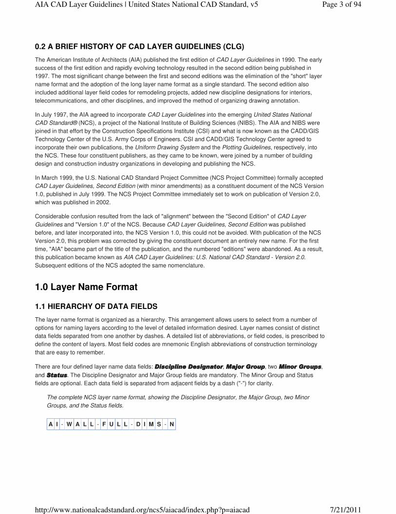
There are four defined layer name data fields: DisciplineDisciplineDisciplineDiscipline DesignatorDesignatorDesignatorDesignator, Major GroupMajor GroupMajor GroupMajor Group, two Minor GroupsMinor GroupsMinor GroupsMinor Groups,
and StatusStatusStatusStatus. The Discipline Designator and Major Group fields are mandatory. The Minor Group and Status
fields are optional. Each data field is separated from adjacent fields by a dash ("-") for clarity.
The complete NCS layer name format, showing the Discipline Designator, the Major Group, two Minor
Groups, and the Status fields.
A I - W A L L - F U L L - D I M S - N
0.2 A BRIEF HISTORY OF CAD LAYER GUIDELINES (CLG)
1.0 Layer Name Format
1.1 HIERARCHY OF DATA FIELDS
Page 3 of 94AIA CAD Layer Guidelines | United States National CAD Standard, v5
7/21/2011http://www.nationalcadstandard.org/ncs5/aiacad/index.php?p=aiacad
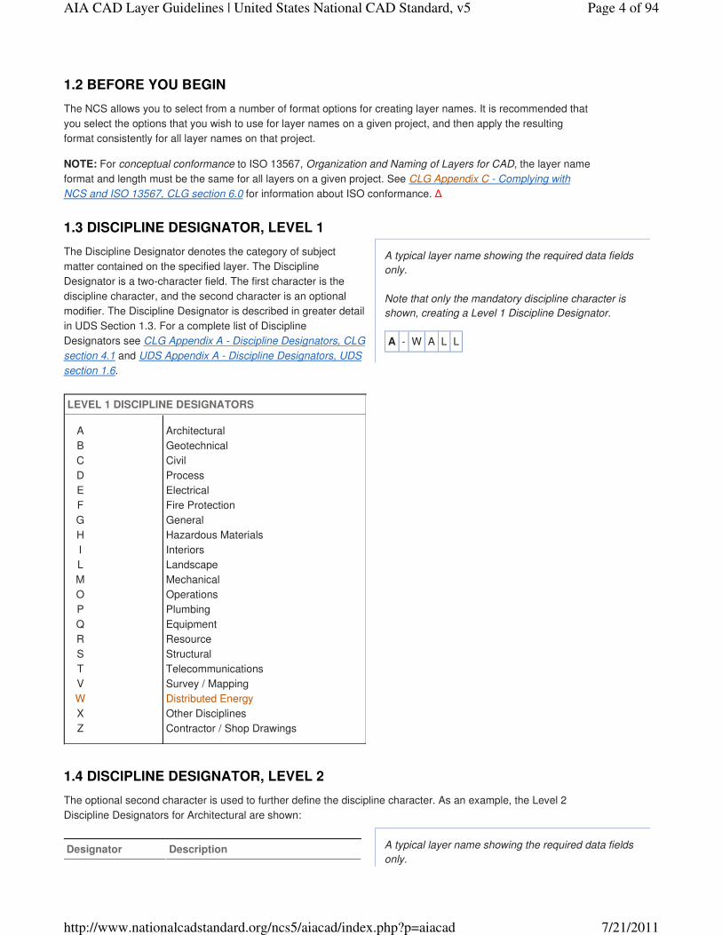
A typical layer name showing the required data fields
only.
Note that only the mandatory discipline character is
shown, creating a Level 1 Discipline Designator.
A - W A L L
A typical layer name showing the required data fields
only.
The NCS allows you to select from a number of format options for creating layer names. It is recommended that
you select the options that you wish to use for layer names on a given project, and then apply the resulting
format consistently for all layer names on that project.
NOTE: For conceptual conformance to ISO 13567, Organization and Naming of Layers for CAD, the layer name
format and length must be the same for all layers on a given project. See CLG Appendix C - Complying with
NCS and ISO 13567, CLG section 6.0 for information about ISO conformance. ∆
The Discipline Designator denotes the category of subject
matter contained on the specified layer. The Discipline
Designator is a two-character field. The first character is the
discipline character, and the second character is an optional
modifier. The Discipline Designator is described in greater detail
in UDS Section 1.3. For a complete list of Discipline
Designators see CLG Appendix A - Discipline Designators, CLG
section 4.1 and UDS Appendix A - Discipline Designators, UDS
section 1.6.
LEVEL 1 DISCIPLINE DESIGNATORS
A
B
C
D
E
F
G
H
I
L
M
O
P
Q
R
S
T
V
W
X
Z
Architectural
Geotechnical
Civil
Process
Electrical
Fire Protection
General
Hazardous Materials
Interiors
Landscape
Mechanical
Operations
Plumbing
Equipment
Resource
Structural
Telecommunications
Survey / Mapping
Distributed Energy
Other Disciplines
Contractor / Shop Drawings
The optional second character is used to further define the discipline character. As an example, the Level 2
Discipline Designators for Architectural are shown:
Designator Description
1.2 BEFORE YOU BEGIN
1.3 DISCIPLINE DESIGNATOR, LEVEL 1
1.4 DISCIPLINE DESIGNATOR, LEVEL 2
Page 4 of 94AIA CAD Layer Guidelines | United States National CAD Standard, v5
7/21/2011http://www.nationalcadstandard.org/ncs5/aiacad/index.php?p=aiacad
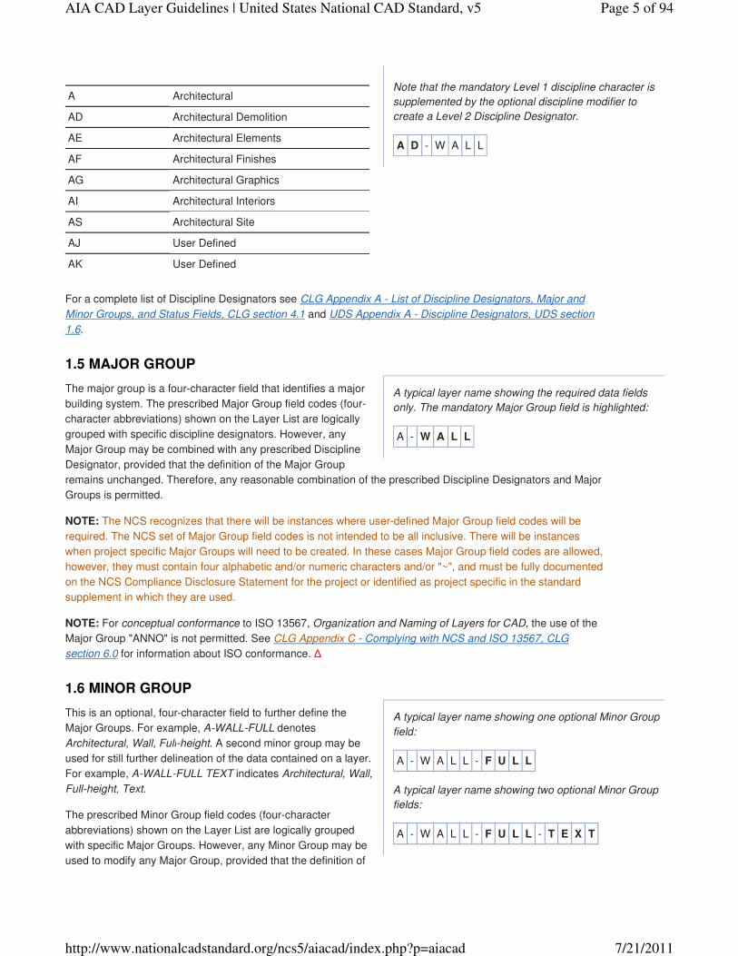
Note that the mandatory Level 1 discipline character is
supplemented by the optional discipline modifier to
create a Level 2 Discipline Designator.
A D - W A L L
A typical layer name showing the required data fields
only. The mandatory Major Group field is highlighted:
A - W A L L
A typical layer name showing one optional Minor Group
field:
A - W A L L - F U L L
A typical layer name showing two optional Minor Group
fields:
A - W A L L - F U L L - T E X T
A Architectural
AD Architectural Demolition
AE Architectural Elements
AF Architectural Finishes
AG Architectural Graphics
AI Architectural Interiors
AS Architectural Site
AJ User Defined
AK User Defined
For a complete list of Discipline Designators see CLG Appendix A - List of Discipline Designators, Major and
Minor Groups, and Status Fields, CLG section 4.1 and UDS Appendix A - Discipline Designators, UDS section
1.6.
The major group is a four-character field that identifies a major
building system. The prescribed Major Group field codes (four-
character abbreviations) shown on the Layer List are logically
grouped with specific discipline designators. However, any
Major Group may be combined with any prescribed Discipline
Designator, provided that the definition of the Major Group
remains unchanged. Therefore, any reasonable combination of the prescribed Discipline Designators and Major
Groups is permitted.
NOTE: The NCS recognizes that there will be instances where user-defined Major Group field codes will be
required. The NCS set of Major Group field codes is not intended to be all inclusive. There will be instances
when project specific Major Groups will need to be created. In these cases Major Group field codes are allowed,
however, they must contain four alphabetic and/or numeric characters and/or "~", and must be fully documented
on the NCS Compliance Disclosure Statement for the project or identified as project specific in the standard
supplement in which they are used.
NOTE: For conceptual conformance to ISO 13567, Organization and Naming of Layers for CAD, the use of the
Major Group "ANNO" is not permitted. See CLG Appendix C - Complying with NCS and ISO 13567, CLG
section 6.0 for information about ISO conformance. ∆
This is an optional, four-character field to further define the
Major Groups. For example, A-WALL-FULL denotes
Architectural, Wall, Full-height. A second minor group may be
used for still further delineation of the data contained on a layer.
For example, A-WALL-FULL TEXT indicates Architectural, Wall,
Full-height, Text.
The prescribed Minor Group field codes (four-character
abbreviations) shown on the Layer List are logically grouped
with specific Major Groups. However, any Minor Group may be
used to modify any Major Group, provided that the definition of
1.5 MAJOR GROUP
1.6 MINOR GROUP
Page 5 of 94AIA CAD Layer Guidelines | United States National CAD Standard, v5
7/21/2011http://www.nationalcadstandard.org/ncs5/aiacad/index.php?p=aiacad
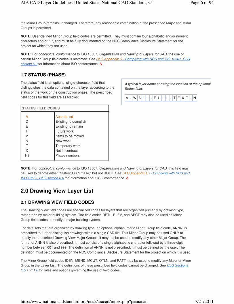
A typical layer name showing the location of the optional
Status field:
A - W A L L - F U L L - T E X T - N
the Minor Group remains unchanged. Therefore, any reasonable combination of the prescribed Major and Minor
Groups is permitted.
NOTE: User-defined Minor Group field codes are permitted. They must contain four alphabetic and/or numeric
characters and/or "~", and must be fully documented on the NCS Compliance Disclosure Statement for the
project on which they are used.
NOTE: For conceptual conformance to ISO 13567, Organization and Naming of Layers for CAD, the use of
certain Minor Group field codes is restricted. See CLG Appendix C - Complying with NCS and ISO 13567, CLG
section 6.0 for information about ISO conformance. ∆
The status field is an optional single-character field that
distinguishes the data contained on the layer according to the
status of the work or the construction phase. The prescribed
field codes for this field are as follows:
STATUS FIELD CODES
A
D
E
F
M
N
T
X
1-9
Abandoned
Existing to demolish
Existing to remain
Future work
Items to be moved
New work
Temporary work
Not in contract
Phase numbers
NOTE: For conceptual conformance to ISO 13567, Organization and Naming of Layers for CAD, this field may
be used to denote either "Status" OR "Phase," but not BOTH. See CLG Appendix C - Complying with NCS and
ISO 13567, CLG section 6.0 for information about ISO conformance. ∆
The Drawing View field codes are specialized codes for layers that are organized primarily by drawing type,
rather than by major building system. The field codes DETL, ELEV, and SECT may also be used as Minor
Group field codes to modify a major building system.
For data sets that are organized by drawing type, an optional alphanumeric Minor Group field code, ANNN, is
prescribed to further distinguish drawings within a single CAD file. This Minor Group may be used ONLY to
modify the prescribed Drawing View Major Groups; it may not be used to modify any other Major Group. The
format of ANNN is also prescribed. It must consist of a single alphabetic character followed by a three-digit
number between 001 and 999. The definition of ANNN is not prescribed; it must be defined by the user. The
definition must be documented on the NCS Compliance Disclosure Statement for the project on which it is used.
The Minor Group field codes IDEN, MBND, MCUT, OTLN, and PATT may be used to modify any Major or Minor
Group in the Layer List. The definitions of these prescribed field codes cannot be changed. See CLG Sections
1.5 and 1.6 for rules and options governing the use of field codes.
1.7 STATUS (PHASE)
2.0 Drawing View Layer List
2.1 DRAWING VIEW FIELD CODES
Page 6 of 94AIA CAD Layer Guidelines | United States National CAD Standard, v5
7/21/2011http://www.nationalcadstandard.org/ncs5/aiacad/index.php?p=aiacad
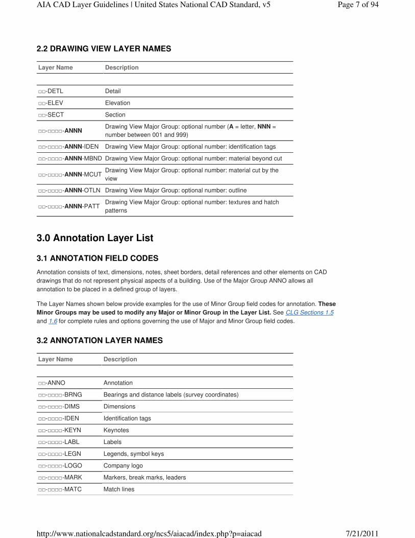
Layer Name Description
□□-DETL Detail
□□-ELEV Elevation
□□-SECT Section
□□-□□□□-ANNNDrawing View Major Group: optional number (A = letter, NNN =
number between 001 and 999)
□□-□□□□-ANNN-IDEN Drawing View Major Group: optional number: identification tags
□□-□□□□-ANNN-MBND Drawing View Major Group: optional number: material beyond cut
□□-□□□□-ANNN-MCUTDrawing View Major Group: optional number: material cut by the
view
□□-□□□□-ANNN-OTLN Drawing View Major Group: optional number: outline
□□-□□□□-ANNN-PATTDrawing View Major Group: optional number: textures and hatch
patterns
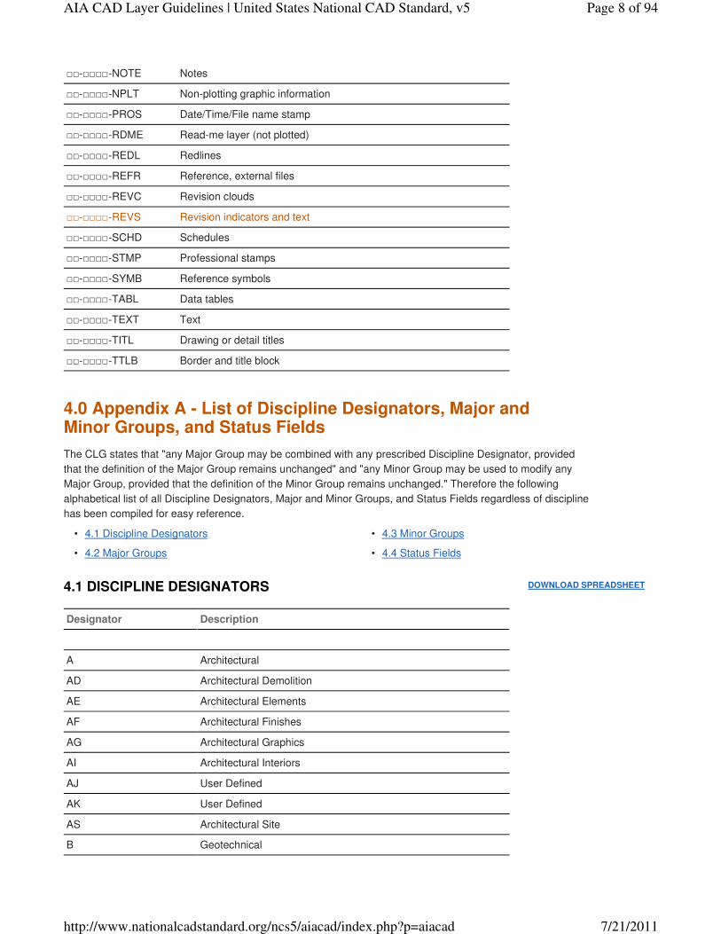
Annotation consists of text, dimensions, notes, sheet borders, detail references and other elements on CAD
drawings that do not represent physical aspects of a building. Use of the Major Group ANNO allows all
annotation to be placed in a defined group of layers.
The Layer Names shown below provide examples for the use of Minor Group field codes for annotation. These
Minor Groups may be used to modify any Major or Minor Group in the Layer List. See CLG Sections 1.5
and 1.6 for complete rules and options governing the use of Major and Minor Group field codes.
Layer Name Description
□□-ANNO Annotation
□□-□□□□-BRNG Bearings and distance labels (survey coordinates)
□□-□□□□-DIMS Dimensions
□□-□□□□-IDEN Identification tags
□□-□□□□-KEYN Keynotes
□□-□□□□-LABL Labels
□□-□□□□-LEGN Legends, symbol keys
□□-□□□□-LOGO Company logo
□□-□□□□-MARK Markers, break marks, leaders
□□-□□□□-MATC Match lines
2.2 DRAWING VIEW LAYER NAMES
3.0 Annotation Layer List
3.1 ANNOTATION FIELD CODES
3.2 ANNOTATION LAYER NAMES
Page 7 of 94AIA CAD Layer Guidelines | United States National CAD Standard, v5
7/21/2011http://www.nationalcadstandard.org/ncs5/aiacad/index.php?p=aiacad
DOWNLOAD SPREADSHEET
□□-□□□□-NOTE Notes
□□-□□□□-NPLT Non-plotting graphic information
□□-□□□□-PROS Date/Time/File name stamp
□□-□□□□-RDME Read-me layer (not plotted)
□□-□□□□-REDL Redlines
□□-□□□□-REFR Reference, external files
□□-□□□□-REVC Revision clouds
□□-□□□□-REVS Revision indicators and text
□□-□□□□-SCHD Schedules
□□-□□□□-STMP Professional stamps
□□-□□□□-SYMB Reference symbols
□□-□□□□-TABL Data tables
□□-□□□□-TEXT Text
□□-□□□□-TITL Drawing or detail titles
□□-□□□□-TTLB Border and title block
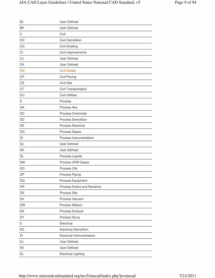
The CLG states that "any Major Group may be combined with any prescribed Discipline Designator, provided
that the definition of the Major Group remains unchanged" and "any Minor Group may be used to modify any
Major Group, provided that the definition of the Minor Group remains unchanged." Therefore the following
alphabetical list of all Discipline Designators, Major and Minor Groups, and Status Fields regardless of discipline
has been compiled for easy reference.
4.1 Discipline Designators•
4.2 Major Groups•
4.3 Minor Groups•
4.4 Status Fields•
Designator Description
A Architectural
AD Architectural Demolition
AE Architectural Elements
AF Architectural Finishes
AG Architectural Graphics
AI Architectural Interiors
AJ User Defined
AK User Defined
AS Architectural Site
B Geotechnical
4.0 Appendix A - List of Discipline Designators, Major and Minor Groups, and Status Fields
4.1 DISCIPLINE DESIGNATORS
Page 8 of 94AIA CAD Layer Guidelines | United States National CAD Standard, v5
7/21/2011http://www.nationalcadstandard.org/ncs5/aiacad/index.php?p=aiacad
BJ User Defined
BK User Defined
C Civil
CD Civil Demolition
CG Civil Grading
CI Civil Improvements
CJ User Defined
CK User Defined
CN Civil Nodes
CP Civil Paving
CS Civil Site
CT Civil Transportation
CU Civil Utilities
D Process
DA Process Airs
DC Process Chemicals
DD Process Demolition
DE Process Electrical
DG Process Gases
DI Process Instrumentation
DJ User Defined
DK User Defined
DL Process Liquids
DM Process HPM Gases
DO Process Oils
DP Process Piping
DQ Process Equipment
DR Process Drains and Reclaims
DS Process Site
DV Process Vacuum
DW Process Waters
DX Process Exhaust
DY Process Slurry
E Electrical
ED Electrical Demolition
EI Electrical Instrumentation
EJ User Defined
EK User Defined
EL Electrical Lighting
Page 9 of 94AIA CAD Layer Guidelines | United States National CAD Standard, v5
7/21/2011http://www.nationalcadstandard.org/ncs5/aiacad/index.php?p=aiacad
EP Electrical Power
ES Electrical Site
ET Electrical Telecommunications
EY Electrical Auxiliary Systems
F Fire Protection
FA Fire Detection and Alarm
FJ User Defined
FK User Defined
FX Fire Suppression
G General
GC General Contractual
GI General Informational
GJ User Defined
GK User Defined
GR General Resource
H Hazardous Materials
HA Hazardous Materials Asbestos
HC Hazardous Materials Chemicals
HJ User Defined
HK User Defined
HL Hazardous Materials Lead
HP Hazardous Materials PCB
HR Hazardous Materials Refrigerants
I Interior
ID Interior Demolition
IF Interior Furnishings
IG Interior Graphics
IJ User Defined
IK User Defined
IN Interior Design
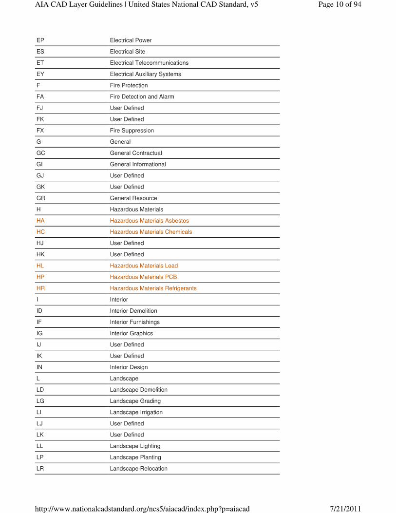
L Landscape
LD Landscape Demolition
LG Landscape Grading
LI Landscape Irrigation
LJ User Defined
LK User Defined
LL Landscape Lighting
LP Landscape Planting
LR Landscape Relocation
Page 10 of 94AIA CAD Layer Guidelines | United States National CAD Standard, v5
7/21/2011http://www.nationalcadstandard.org/ncs5/aiacad/index.php?p=aiacad
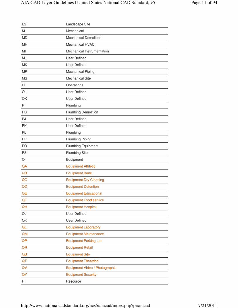
LS Landscape Site
M Mechanical
MD Mechanical Demolition
MH Mechanical HVAC
MI Mechanical Instrumentation
MJ User Defined
MK User Defined
MP Mechanical Piping
MS Mechanical Site
O Operations
OJ User Defined
OK User Defined
P Plumbing
PD Plumbing Demolition
PJ User Defined
PK User Defined
PL Plumbing
PP Plumbing Piping
PQ Plumbing Equipment
PS Plumbing Site
Q Equipment
QA Equipment Athletic
QB Equipment Bank
QC Equipment Dry Cleaning
QD Equipment Detention
QE Equipment Educational
QF Equipment Food service
QH Equipment Hospital
QJ User Defined
QK User Defined
QL Equipment Laboratory
QM Equipment Maintenance
QP Equipment Parking Lot
QR Equipment Retail
QS Equipment Site
QT Equipment Theatrical
QV Equipment Video / Photographic
QY Equipment Security
R Resource
Page 11 of 94AIA CAD Layer Guidelines | United States National CAD Standard, v5
7/21/2011http://www.nationalcadstandard.org/ncs5/aiacad/index.php?p=aiacad
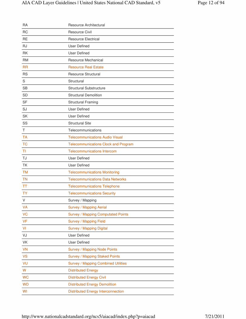
RA Resource Architectural
RC Resource Civil
RE Resource Electrical
RJ User Defined
RK User Defined
RM Resource Mechanical
RR Resource Real Estate
RS Resource Structural
S Structural
SB Structural Substructure
SD Structural Demolition
SF Structural Framing
SJ User Defined
SK User Defined
SS Structural Site
T Telecommunications
TA Telecommunications Audio Visual
TC Telecommunications Clock and Program
TI Telecommunications Intercom
TJ User Defined
TK User Defined
TM Telecommunications Monitoring
TN Telecommunications Data Networks
TT Telecommunications Telephone
TY Telecommunications Security
V Survey / Mapping
VA Survey / Mapping Aerial
VC Survey / Mapping Computated Points
VF Survey / Mapping Field
VI Survey / Mapping Digital
VJ User Defined
VK User Defined
VN Survey / Mapping Node Points
VS Survey / Mapping Staked Points
VU Survey / Mapping Combined Utilities
W Distributed Energy
WC Distributed Energy Civil
WD Distributed Energy Demolition
WI Distributed Energy Interconnection
Page 12 of 94AIA CAD Layer Guidelines | United States National CAD Standard, v5
7/21/2011http://www.nationalcadstandard.org/ncs5/aiacad/index.php?p=aiacad
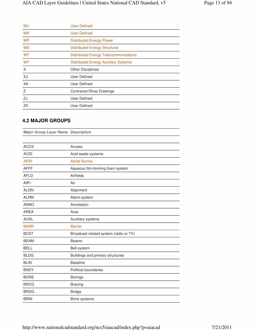
WJ User Defined
WK User Defined
WP Distributed Energy Power
WS Distributed Energy Structural
WT Distributed Energy Telecommunications
WY Distributed Energy Auxiliary Systems
X Other Disciplines
XJ User Defined
XK User Defined
Z Contractor/Shop Drawings
ZJ User Defined
ZK User Defined
Major Group Layer Name Description
ACCS Access
ACID Acid waste systems
AERI Aerial Survey
AFFF Aqueous film-forming foam system
AFLD Airfields
AIR~ Air
ALGN Alignment
ALRM Alarm system
ANNO Annotation
AREA Area
AUXL Auxiliary systems
BARR Barrier
BCST Broadcast related system (radio or TV)
BEAM Beams
BELL Bell system
BLDG Buildings and primary structures
BLIN Baseline
BNDY Political boundaries
BORE Borings
BRCG Bracing
BRDG Bridge
BRIN Brine systems
4.2 MAJOR GROUPS
Page 13 of 94AIA CAD Layer Guidelines | United States National CAD Standard, v5
7/21/2011http://www.nationalcadstandard.org/ncs5/aiacad/index.php?p=aiacad
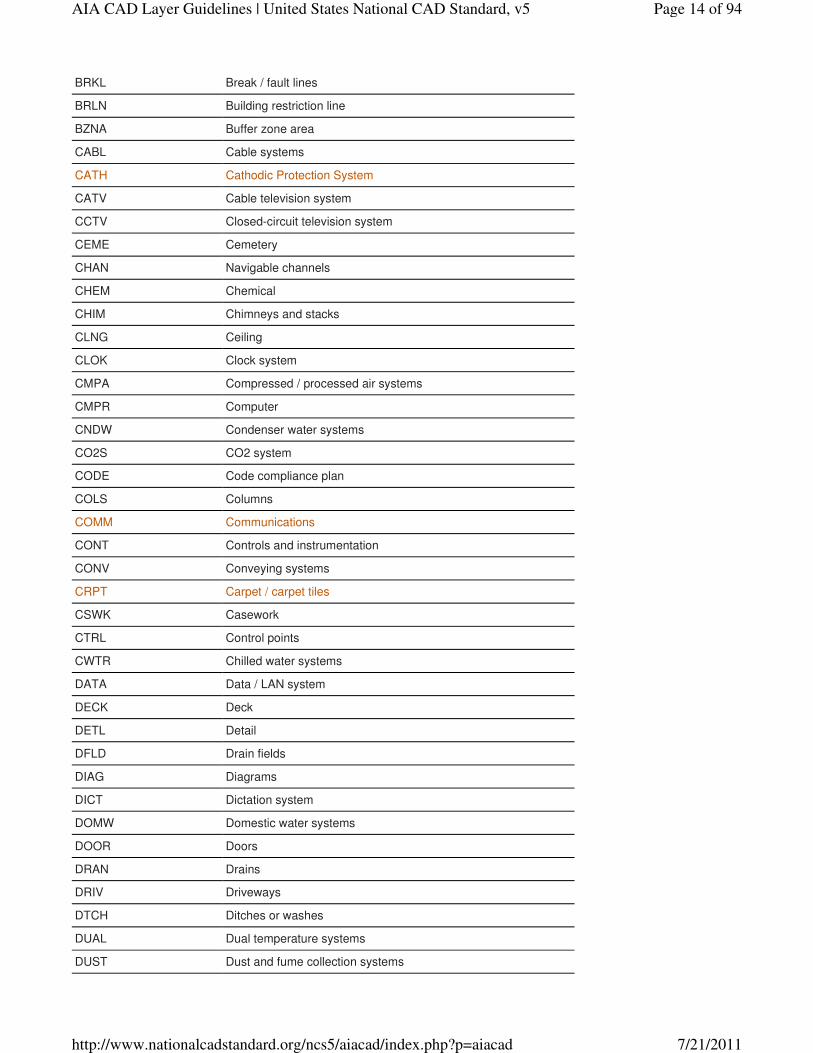
BRKL Break / fault lines
BRLN Building restriction line
BZNA Buffer zone area
CABL Cable systems
CATH Cathodic Protection System
CATV Cable television system
CCTV Closed-circuit television system
CEME Cemetery
CHAN Navigable channels
CHEM Chemical
CHIM Chimneys and stacks
CLNG Ceiling
CLOK Clock system
CMPA Compressed / processed air systems
CMPR Computer
CNDW Condenser water systems
CO2S CO2 system
CODE Code compliance plan
COLS Columns
COMM Communications
CONT Controls and instrumentation
CONV Conveying systems
CRPT Carpet / carpet tiles
CSWK Casework
CTRL Control points
CWTR Chilled water systems
DATA Data / LAN system
DECK Deck
DETL Detail
DFLD Drain fields
DIAG Diagrams
DICT Dictation system
DOMW Domestic water systems
DOOR Doors
DRAN Drains
DRIV Driveways
DTCH Ditches or washes
DUAL Dual temperature systems
DUST Dust and fume collection systems
Page 14 of 94AIA CAD Layer Guidelines | United States National CAD Standard, v5
7/21/2011http://www.nationalcadstandard.org/ncs5/aiacad/index.php?p=aiacad
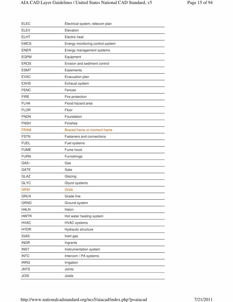
ELEC Electrical system, telecom plan
ELEV Elevation
ELHT Electric heat
EMCS Energy monitoring control system
ENER Energy management systems
EQPM Equipment
EROS Erosion and sediment control
ESMT Easements
EVAC Evacuation plan
EXHS Exhaust system
FENC Fences
FIRE Fire protection
FLHA Flood hazard area
FLOR Floor
FNDN Foundation
FNSH Finishes
FRAM Braced frame or moment frame
FSTN Fasteners and connections
FUEL Fuel systems
FUME Fume hood
FURN Furnishings
GAS~ Gas
GATE Gate
GLAZ Glazing
GLYC Glycol systems
GRID Grids
GRLN Grade line
GRND Ground system
HALN Halon
HWTR Hot water heating system
HVAC HVAC systems
HYDR Hydraulic structure
IGAS Inert gas
INGR Ingrants
INST Instrumentation system
INTC Intercom / PA systems
IRRG Irrigation
JNTS Joints
JOIS Joists
Page 15 of 94AIA CAD Layer Guidelines | United States National CAD Standard, v5
7/21/2011http://www.nationalcadstandard.org/ncs5/aiacad/index.php?p=aiacad
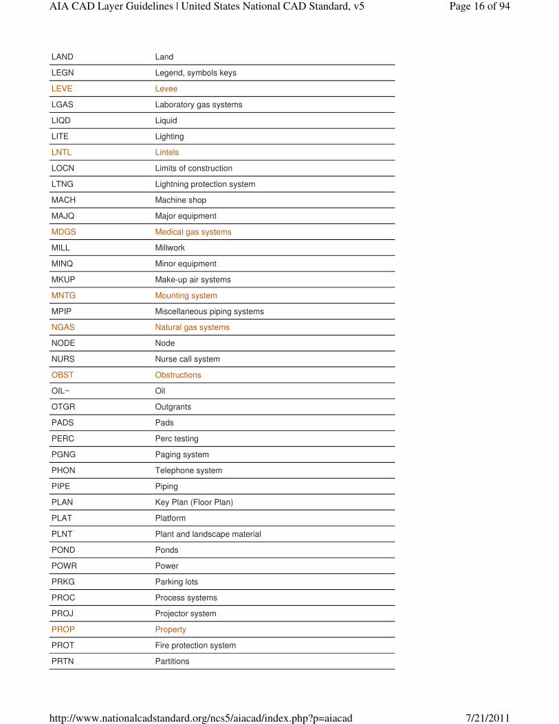
LAND Land
LEGN Legend, symbols keys
LEVE Levee
LGAS Laboratory gas systems
LIQD Liquid
LITE Lighting
LNTL Lintels
LOCN Limits of construction
LTNG Lightning protection system
MACH Machine shop
MAJQ Major equipment
MDGS Medical gas systems
MILL Millwork
MINQ Minor equipment
MKUP Make-up air systems
MNTG Mounting system
MPIP Miscellaneous piping systems
NGAS Natural gas systems
NODE Node
NURS Nurse call system
OBST Obstructions
OIL~ Oil
OTGR Outgrants
PADS Pads
PERC Perc testing
PGNG Paging system
PHON Telephone system
PIPE Piping
PLAN Key Plan (Floor Plan)
PLAT Platform
PLNT Plant and landscape material
POND Ponds
POWR Power
PRKG Parking lots
PROC Process systems
PROJ Projector system
PROP Property
PROT Fire protection system
PRTN Partitions
Page 16 of 94AIA CAD Layer Guidelines | United States National CAD Standard, v5
7/21/2011http://www.nationalcadstandard.org/ncs5/aiacad/index.php?p=aiacad
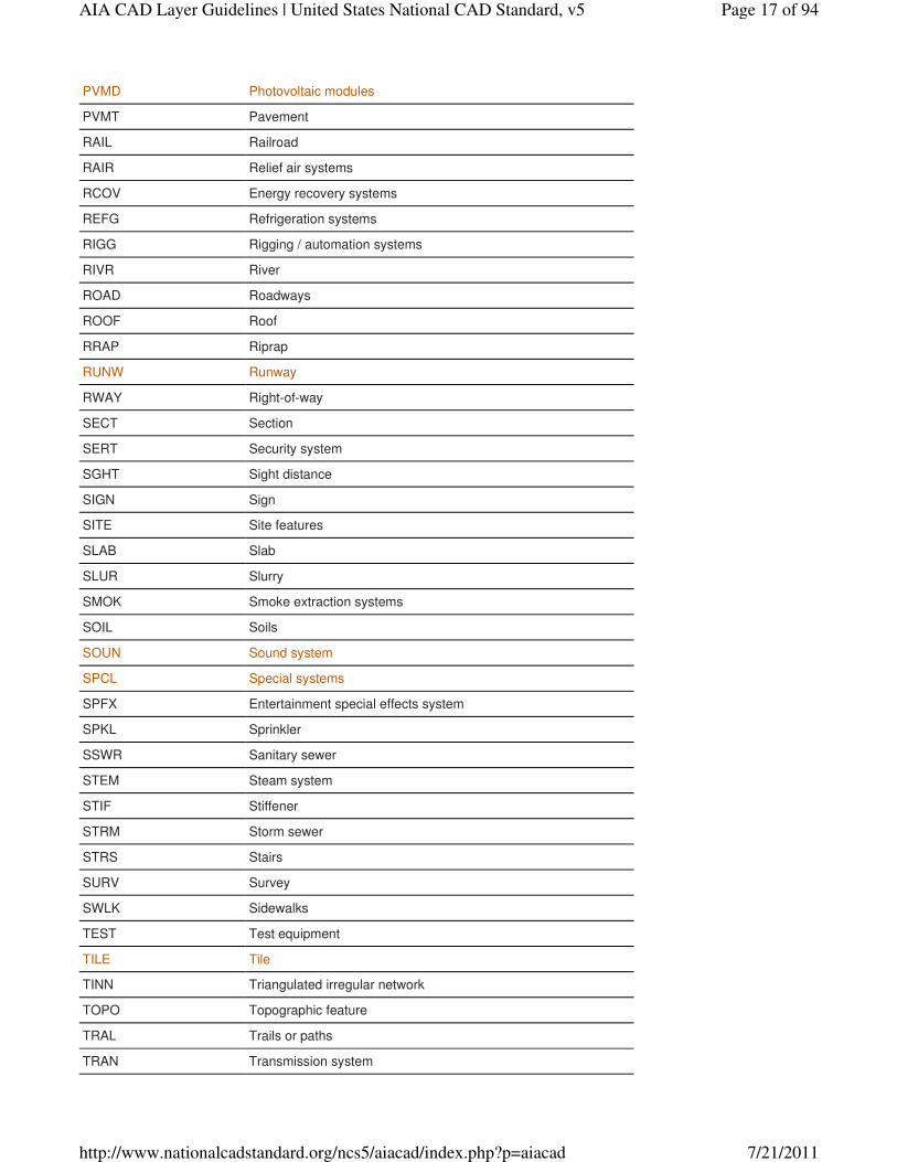
PVMD Photovoltaic modules
PVMT Pavement
RAIL Railroad
RAIR Relief air systems
RCOV Energy recovery systems
REFG Refrigeration systems
RIGG Rigging / automation systems
RIVR River
ROAD Roadways
ROOF Roof
RRAP Riprap
RUNW Runway
RWAY Right-of-way
SECT Section
SERT Security system
SGHT Sight distance
SIGN Sign
SITE Site features
SLAB Slab
SLUR Slurry
SMOK Smoke extraction systems
SOIL Soils
SOUN Sound system
SPCL Special systems
SPFX Entertainment special effects system
SPKL Sprinkler
SSWR Sanitary sewer
STEM Steam system
STIF Stiffener
STRM Storm sewer
STRS Stairs
SURV Survey
SWLK Sidewalks
TEST Test equipment
TILE Tile
TINN Triangulated irregular network
TOPO Topographic feature
TRAL Trails or paths
TRAN Transmission system
Page 17 of 94AIA CAD Layer Guidelines | United States National CAD Standard, v5
7/21/2011http://www.nationalcadstandard.org/ncs5/aiacad/index.php?p=aiacad

TRUS Trusses
TVAN Television antenna system
TVVS Television and video system
UNID Unidentified site objects
UTIL Utilities
VACU Vacuum
VIDO Entertainment projection systems
WALL Walls
WATR Water supply
WETL Wetlands
WIND Wind powered
WWAY Waterway
Minor Group Layer Name Description
025Y 25-year mark
04FT Four feet high
050Y 50-year mark
06FT Six feet high
100Y 100-year mark
200Y 200-year mark
AA~~ Agitation air-system
ABLT Anchor bolts
ABOV Above
ABUT Abutment
ACCS Access
ACFU Fused ac
ACTL Aerial horizontal and vertical control points
ACNF Unfused ac
AGGR Exposed aggregate
AIR~ Air
ALOC Allocation
ALRM Alarm
ALUM Aluminum
AMEX Ammonia exhaust-system
AMW~ Ammonia waste-system
4.3 MINOR GROUPS
Page 18 of 94AIA CAD Layer Guidelines | United States National CAD Standard, v5
7/21/2011http://www.nationalcadstandard.org/ncs5/aiacad/index.php?p=aiacad
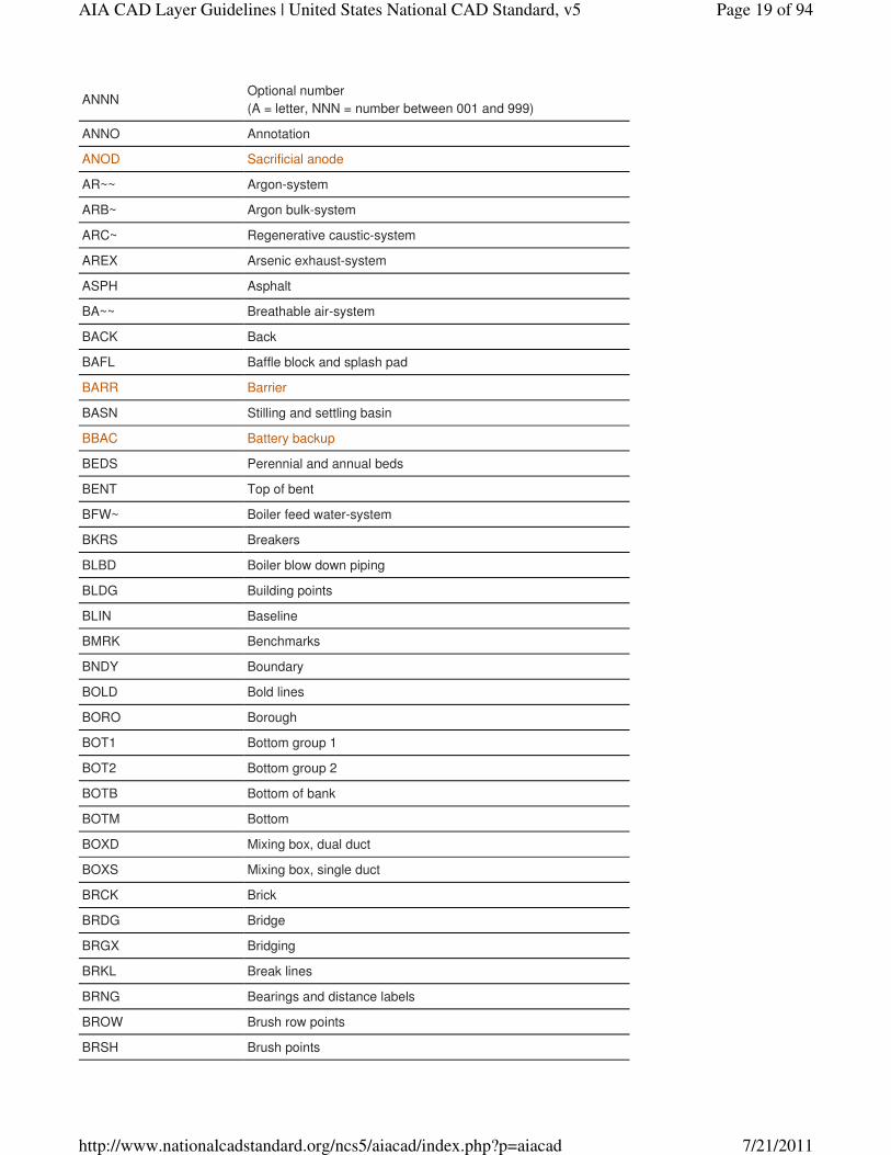
ANNNOptional number
(A = letter, NNN = number between 001 and 999)
ANNO Annotation
ANOD Sacrificial anode
AR~~ Argon-system
ARB~ Argon bulk-system
ARC~ Regenerative caustic-system
AREX Arsenic exhaust-system
ASPH Asphalt
BA~~ Breathable air-system
BACK Back
BAFL Baffle block and splash pad
BARR Barrier
BASN Stilling and settling basin
BBAC Battery backup
BEDS Perennial and annual beds
BENT Top of bent
BFW~ Boiler feed water-system
BKRS Breakers
BLBD Boiler blow down piping
BLDG Building points
BLIN Baseline
BMRK Benchmarks
BNDY Boundary
BOLD Bold lines
BORO Borough
BOT1 Bottom group 1
BOT2 Bottom group 2
BOTB Bottom of bank
BOTM Bottom
BOXD Mixing box, dual duct
BOXS Mixing box, single duct
BRCK Brick
BRDG Bridge
BRGX Bridging
BRKL Break lines
BRNG Bearings and distance labels
BROW Brush row points
BRSH Brush points
Page 19 of 94AIA CAD Layer Guidelines | United States National CAD Standard, v5
7/21/2011http://www.nationalcadstandard.org/ncs5/aiacad/index.php?p=aiacad
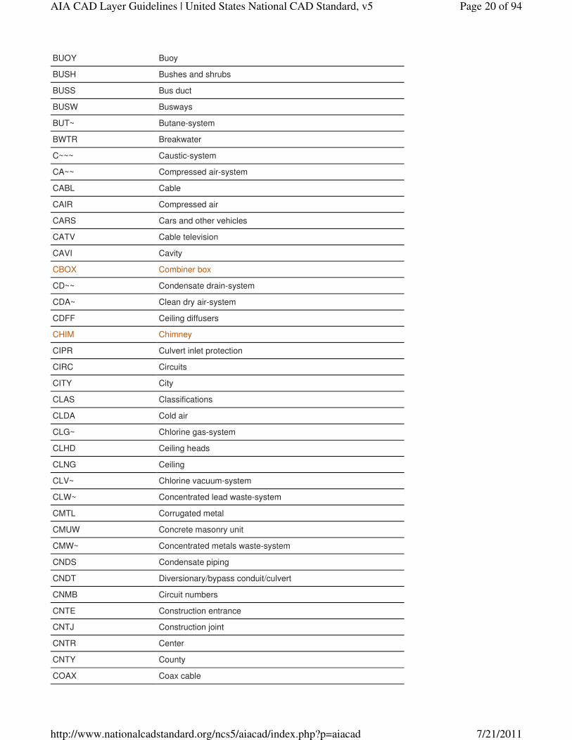
BUOY Buoy
BUSH Bushes and shrubs
BUSS Bus duct
BUSW Busways
BUT~ Butane-system
BWTR Breakwater
C~~~ Caustic-system
CA~~ Compressed air-system
CABL Cable
CAIR Compressed air
CARS Cars and other vehicles
CATV Cable television
CAVI Cavity
CBOX Combiner box
CD~~ Condensate drain-system
CDA~ Clean dry air-system
CDFF Ceiling diffusers
CHIM Chimney
CIPR Culvert inlet protection
CIRC Circuits
CITY City
CLAS Classifications
CLDA Cold air
CLG~ Chlorine gas-system
CLHD Ceiling heads
CLNG Ceiling
CLV~ Chlorine vacuum-system
CLW~ Concentrated lead waste-system
CMTL Corrugated metal
CMUW Concrete masonry unit
CMW~ Concentrated metals waste-system
CNDS Condensate piping
CNDT Diversionary/bypass conduit/culvert
CNMB Circuit numbers
CNTE Construction entrance
CNTJ Construction joint
CNTR Center
CNTY County
COAX Coax cable
Page 20 of 94AIA CAD Layer Guidelines | United States National CAD Standard, v5
7/21/2011http://www.nationalcadstandard.org/ncs5/aiacad/index.php?p=aiacad

COFF Coffer dam
CONC Concrete
CONI Coniferous trees
CONS Conservation
CORP Corporation
COVR Coverage
CPIP Cold water piping
CRIT Critical
CRKT Crickets
CSTG Construction/Grading
CSWK Casework
CTLA Controlled access
CTLJ Control joint
CTNR Container or planter
CUPW Copper plating waste-system
CURB Curb
CURR Impress current
CURT Curtain
CURV Curve
CURW Copper rinse waste-system
CUSW Copper slurry waste-system
CV~~ Chemical vacuum-system
DACL De-Authorized channel limits, anchorages, etc.
DAM~ Dam
DASP Description attributes for survey points
DATA Data
DCFU Fused dc
DCNF Unfused dc
DDIV Drainage divides
DECK Deck
DEPR Depression
DEV~ Developer-system
DEVC Devices
DFEE Disposed fee
DIAG Diagrams
DIMS Dimensions
DIR~ De-Ionized water return-system
DIRC DI reclaim-system
DIS~ De-Ionized water supply-system
Page 21 of 94AIA CAD Layer Guidelines | United States National CAD Standard, v5
7/21/2011http://www.nationalcadstandard.org/ncs5/aiacad/index.php?p=aiacad
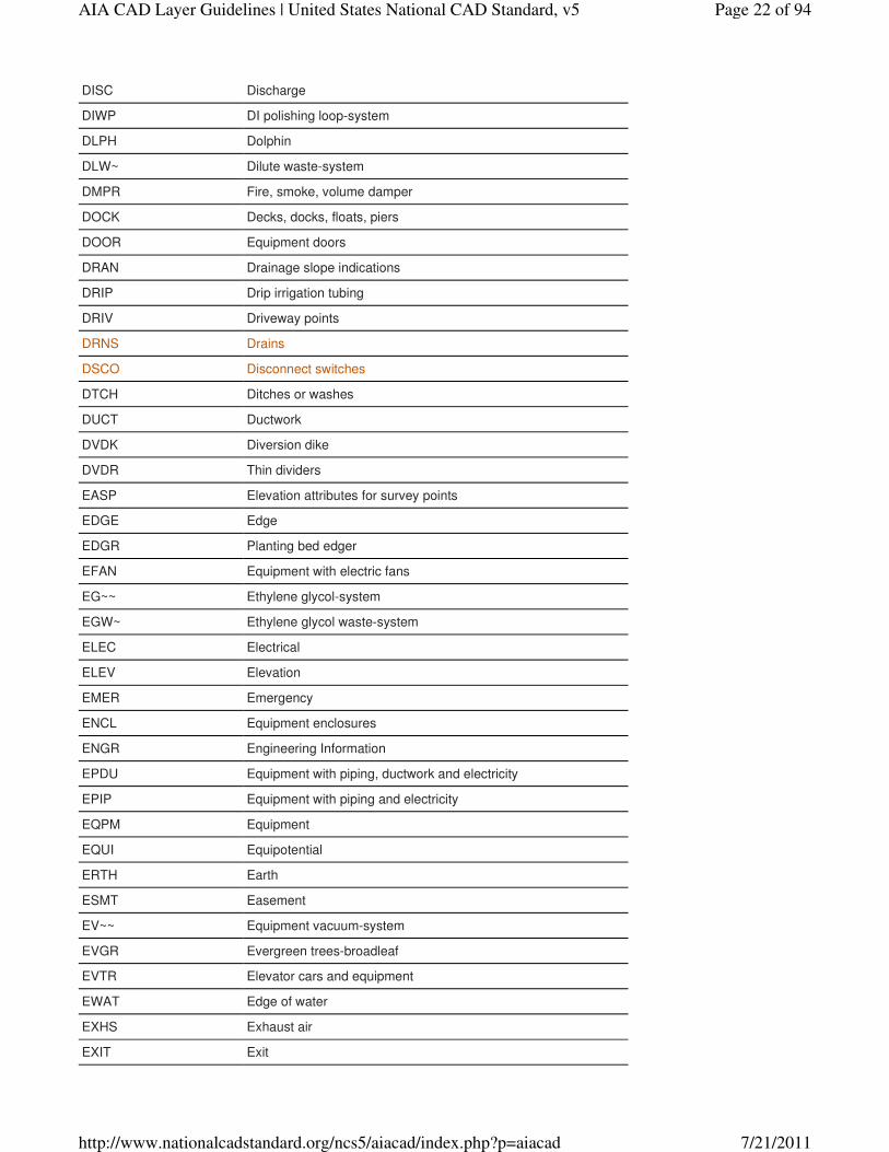
DISC Discharge
DIWP DI polishing loop-system
DLPH Dolphin
DLW~ Dilute waste-system
DMPR Fire, smoke, volume damper
DOCK Decks, docks, floats, piers
DOOR Equipment doors
DRAN Drainage slope indications
DRIP Drip irrigation tubing
DRIV Driveway points
DRNS Drains
DSCO Disconnect switches
DTCH Ditches or washes
DUCT Ductwork
DVDK Diversion dike
DVDR Thin dividers
EASP Elevation attributes for survey points
EDGE Edge
EDGR Planting bed edger
EFAN Equipment with electric fans
EG~~ Ethylene glycol-system
EGW~ Ethylene glycol waste-system
ELEC Electrical
ELEV Elevation
EMER Emergency
ENCL Equipment enclosures
ENGR Engineering Information
EPDU Equipment with piping, ductwork and electricity
EPIP Equipment with piping and electricity
EQPM Equipment
EQUI Equipotential
ERTH Earth
ESMT Easement
EV~~ Equipment vacuum-system
EVGR Evergreen trees-broadleaf
EVTR Elevator cars and equipment
EWAT Edge of water
EXHS Exhaust air
EXIT Exit
Page 22 of 94AIA CAD Layer Guidelines | United States National CAD Standard, v5
7/21/2011http://www.nationalcadstandard.org/ncs5/aiacad/index.php?p=aiacad
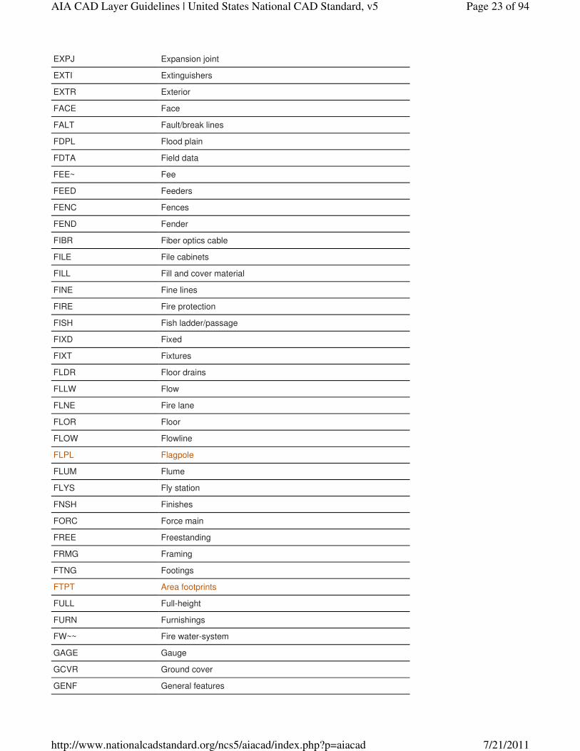
EXPJ Expansion joint
EXTI Extinguishers
EXTR Exterior
FACE Face
FALT Fault/break lines
FDPL Flood plain
FDTA Field data
FEE~ Fee
FEED Feeders
FENC Fences
FEND Fender
FIBR Fiber optics cable
FILE File cabinets
FILL Fill and cover material
FINE Fine lines
FIRE Fire protection
FISH Fish ladder/passage
FIXD Fixed
FIXT Fixtures
FLDR Floor drains
FLLW Flow
FLNE Fire lane
FLOR Floor
FLOW Flowline
FLPL Flagpole
FLUM Flume
FLYS Fly station
FNSH Finishes
FORC Force main
FREE Freestanding
FRMG Framing
FTNG Footings
FTPT Area footprints
FULL Full-height
FURN Furnishings
FW~~ Fire water-system
GAGE Gauge
GCVR Ground cover
GENF General features
Page 23 of 94AIA CAD Layer Guidelines | United States National CAD Standard, v5
7/21/2011http://www.nationalcadstandard.org/ncs5/aiacad/index.php?p=aiacad
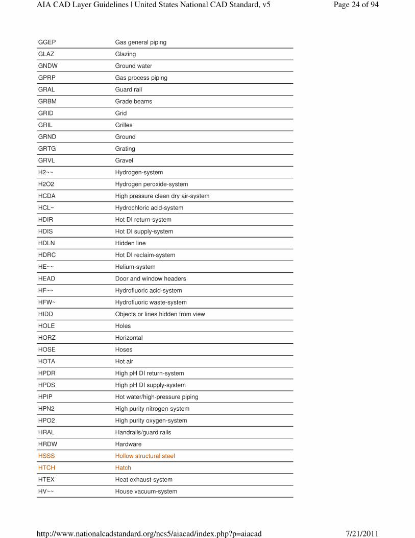
GGEP Gas general piping
GLAZ Glazing
GNDW Ground water
GPRP Gas process piping
GRAL Guard rail
GRBM Grade beams
GRID Grid
GRIL Grilles
GRND Ground
GRTG Grating
GRVL Gravel
H2~~ Hydrogen-system
H2O2 Hydrogen peroxide-system
HCDA High pressure clean dry air-system
HCL~ Hydrochloric acid-system
HDIR Hot DI return-system
HDIS Hot DI supply-system
HDLN Hidden line
HDRC Hot DI reclaim-system
HE~~ Helium-system
HEAD Door and window headers
HF~~ Hydrofluoric acid-system
HFW~ Hydrofluoric waste-system
HIDD Objects or lines hidden from view
HOLE Holes
HORZ Horizontal
HOSE Hoses
HOTA Hot air
HPDR High pH DI return-system
HPDS High pH DI supply-system
HPIP Hot water/high-pressure piping
HPN2 High purity nitrogen-system
HPO2 High purity oxygen-system
HRAL Handrails/guard rails
HRDW Hardware
HSSS Hollow structural steel
HTCH Hatch
HTEX Heat exhaust-system
HV~~ House vacuum-system
Page 24 of 94AIA CAD Layer Guidelines | United States National CAD Standard, v5
7/21/2011http://www.nationalcadstandard.org/ncs5/aiacad/index.php?p=aiacad
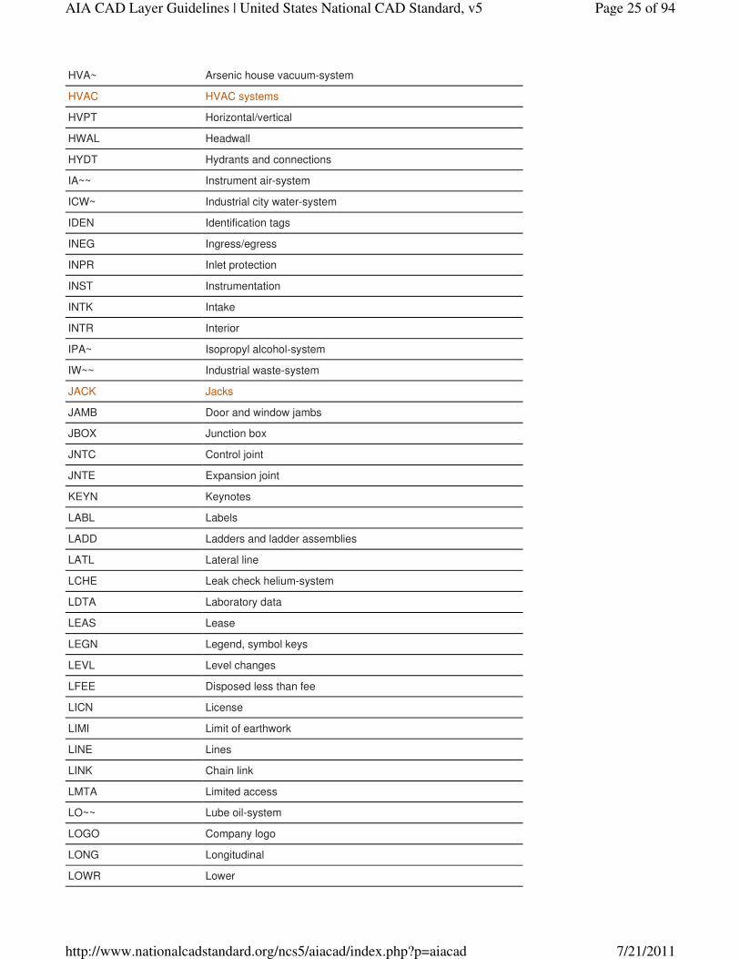
HVA~ Arsenic house vacuum-system
HVAC HVAC systems
HVPT Horizontal/vertical
HWAL Headwall
HYDT Hydrants and connections
IA~~ Instrument air-system
ICW~ Industrial city water-system
IDEN Identification tags
INEG Ingress/egress
INPR Inlet protection
INST Instrumentation
INTK Intake
INTR Interior
IPA~ Isopropyl alcohol-system
IW~~ Industrial waste-system
JACK Jacks
JAMB Door and window jambs
JBOX Junction box
JNTC Control joint
JNTE Expansion joint
KEYN Keynotes
LABL Labels
LADD Ladders and ladder assemblies
LATL Lateral line
LCHE Leak check helium-system
LDTA Laboratory data
LEAS Lease
LEGN Legend, symbol keys
LEVL Level changes
LFEE Disposed less than fee
LICN License
LIMI Limit of earthwork
LINE Lines
LINK Chain link
LMTA Limited access
LO~~ Lube oil-system
LOGO Company logo
LONG Longitudinal
LOWR Lower
Page 25 of 94AIA CAD Layer Guidelines | United States National CAD Standard, v5
7/21/2011http://www.nationalcadstandard.org/ncs5/aiacad/index.php?p=aiacad
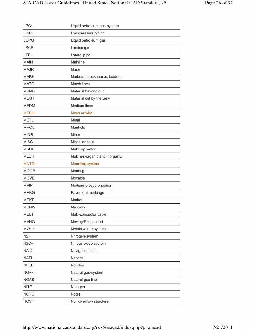
LPG~ Liquid petroleum gas-system
LPIP Low-pressure piping
LQPG Liquid petroleum gas
LSCP Landscape
LTRL Lateral pipe
MAIN Mainline
MAJR Major
MARK Markers, break marks, leaders
MATC Match lines
MBND Material beyond cut
MCUT Material cut by the view
MEDM Medium lines
MESH Mesh or wire
METL Metal
MHOL Manhole
MINR Minor
MISC Miscellaneous
MKUP Make-up water
MLCH Mulches-organic and inorganic
MNTG Mounting system
MOOR Mooring
MOVE Movable
MPIP Medium-pressure piping
MRKG Pavement markings
MRKR Marker
MSNW Masonry
MULT Multi-conductor cable
MVNG Moving/Suspended
MW~~ Metals waste-system
N2~~ Nitrogen-system
N2O~ Nitrous oxide-system
NAID Navigation aids
NATL National
NFEE Non-fee
NG~~ Natural gas-system
NGAS Natural gas line
NITG Nitrogen
NOTE Notes
NOVR Non-overflow structure
Page 26 of 94AIA CAD Layer Guidelines | United States National CAD Standard, v5
7/21/2011http://www.nationalcadstandard.org/ncs5/aiacad/index.php?p=aiacad
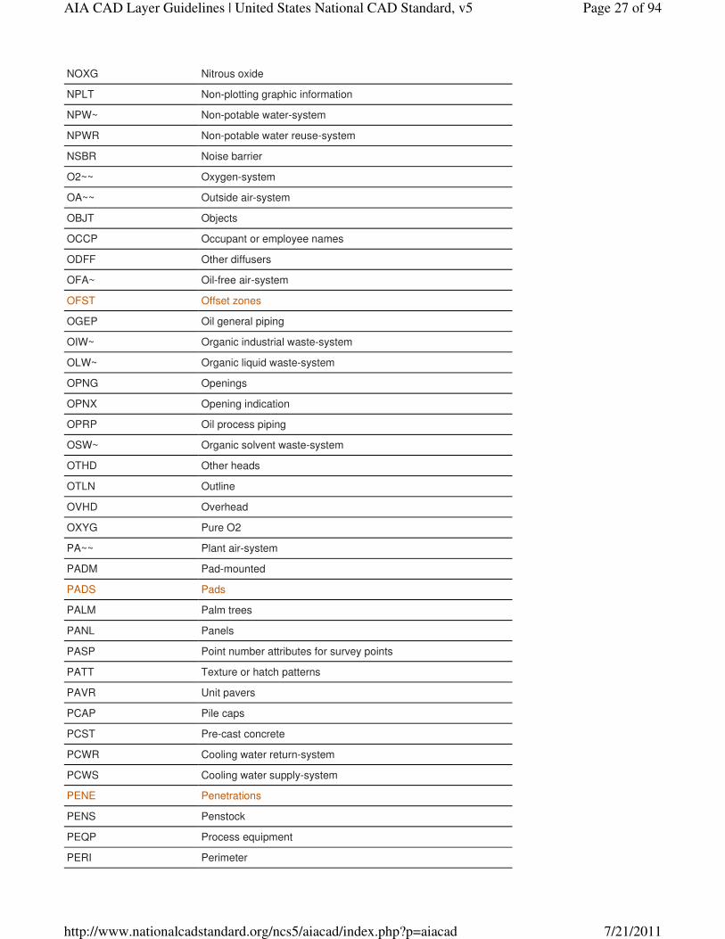
NOXG Nitrous oxide
NPLT Non-plotting graphic information
NPW~ Non-potable water-system
NPWR Non-potable water reuse-system
NSBR Noise barrier
O2~~ Oxygen-system
OA~~ Outside air-system
OBJT Objects
OCCP Occupant or employee names
ODFF Other diffusers
OFA~ Oil-free air-system
OFST Offset zones
OGEP Oil general piping
OIW~ Organic industrial waste-system
OLW~ Organic liquid waste-system
OPNG Openings
OPNX Opening indication
OPRP Oil process piping
OSW~ Organic solvent waste-system
OTHD Other heads
OTLN Outline
OVHD Overhead
OXYG Pure O2
PA~~ Plant air-system
PADM Pad-mounted
PADS Pads
PALM Palm trees
PANL Panels
PASP Point number attributes for survey points
PATT Texture or hatch patterns
PAVR Unit pavers
PCAP Pile caps
PCST Pre-cast concrete
PCWR Cooling water return-system
PCWS Cooling water supply-system
PENE Penetrations
PENS Penstock
PEQP Process equipment
PERI Perimeter
Page 27 of 94AIA CAD Layer Guidelines | United States National CAD Standard, v5
7/21/2011http://www.nationalcadstandard.org/ncs5/aiacad/index.php?p=aiacad
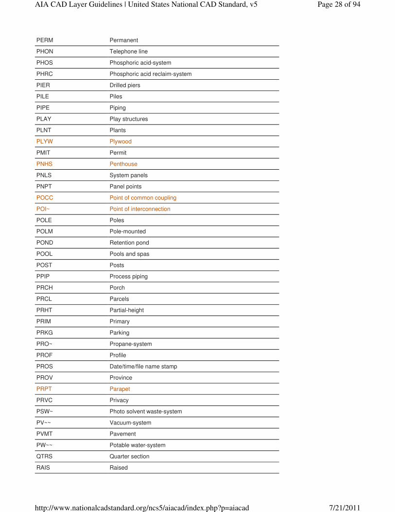
PERM Permanent
PHON Telephone line
PHOS Phosphoric acid-system
PHRC Phosphoric acid reclaim-system
PIER Drilled piers
PILE Piles
PIPE Piping
PLAY Play structures
PLNT Plants
PLYW Plywood
PMIT Permit
PNHS Penthouse
PNLS System panels
PNPT Panel points
POCC Point of common coupling
POI~ Point of interconnection
POLE Poles
POLM Pole-mounted
POND Retention pond
POOL Pools and spas
POST Posts
PPIP Process piping
PRCH Porch
PRCL Parcels
PRHT Partial-height
PRIM Primary
PRKG Parking
PRO~ Propane-system
PROF Profile
PROS Date/time/file name stamp
PROV Province
PRPT Parapet
PRVC Privacy
PSW~ Photo solvent waste-system
PV~~ Vacuum-system
PVMT Pavement
PW~~ Potable water-system
QTRS Quarter section
RAIS Raised
Page 28 of 94AIA CAD Layer Guidelines | United States National CAD Standard, v5
7/21/2011http://www.nationalcadstandard.org/ncs5/aiacad/index.php?p=aiacad
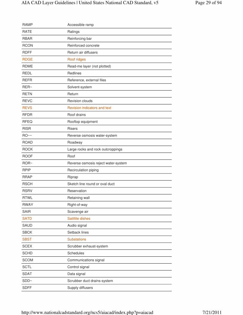
RAMP Accessible ramp
RATE Ratings
RBAR Reinforcing bar
RCON Reinforced concrete
RDFF Return air diffusers
RDGE Roof ridges
RDME Read-me layer (not plotted)
REDL Redlines
REFR Reference, external files
RER~ Solvent-system
RETN Return
REVC Revision clouds
REVS Revision indicators and text
RFDR Roof drains
RFEQ Rooftop equipment
RISR Risers
RO~~ Reverse osmosis water-system
ROAD Roadway
ROCK Large rocks and rock outcroppings
ROOF Roof
ROR~ Reverse osmosis reject water-system
RPIP Recirculation piping
RRAP Riprap
RSCH Sketch line round or oval duct
RSRV Reservation
RTWL Retaining wall
RWAY Right-of-way
SAIR Scavenge air
SATD Satillite dishes
SAUD Audio signal
SBCK Setback lines
SBST Substations
SCEX Scrubber exhaust-system
SCHD Schedules
SCOM Communications signal
SCTL Control signal
SDAT Data signal
SDD~ Scrubber duct drains-system
SDFF Supply diffusers
Page 29 of 94AIA CAD Layer Guidelines | United States National CAD Standard, v5
7/21/2011http://www.nationalcadstandard.org/ncs5/aiacad/index.php?p=aiacad
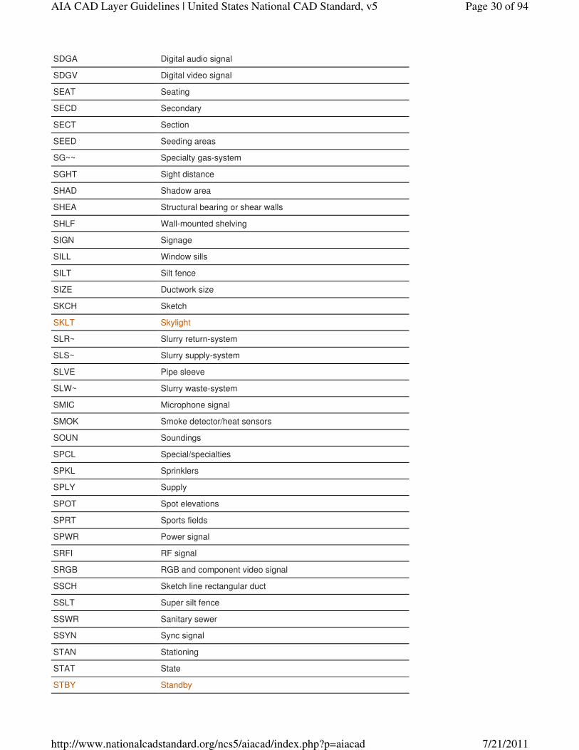
SDGA Digital audio signal
SDGV Digital video signal
SEAT Seating
SECD Secondary
SECT Section
SEED Seeding areas
SG~~ Specialty gas-system
SGHT Sight distance
SHAD Shadow area
SHEA Structural bearing or shear walls
SHLF Wall-mounted shelving
SIGN Signage
SILL Window sills
SILT Silt fence
SIZE Ductwork size
SKCH Sketch
SKLT Skylight
SLR~ Slurry return-system
SLS~ Slurry supply-system
SLVE Pipe sleeve
SLW~ Slurry waste-system
SMIC Microphone signal
SMOK Smoke detector/heat sensors
SOUN Soundings
SPCL Special/specialties
SPKL Sprinklers
SPLY Supply
SPOT Spot elevations
SPRT Sports fields
SPWR Power signal
SRFI RF signal
SRGB RGB and component video signal
SSCH Sketch line rectangular duct
SSLT Super silt fence
SSWR Sanitary sewer
SSYN Sync signal
STAN Stationing
STAT State
STBY Standby
Page 30 of 94AIA CAD Layer Guidelines | United States National CAD Standard, v5
7/21/2011http://www.nationalcadstandard.org/ncs5/aiacad/index.php?p=aiacad

STEL Steel
STEP Steps
STMP Professional stamp
STOR Storage
STRC Structures
STRM Storm Sewer
STRP Striping
STRS Stair treads
SUBA Cabinet sub-assemblies, drawer boxes
SUBD Subdivision (interior) lines
SUBS Sub-surface areas
SULF Sulfuric acid-system
SULR Sulfuric acid reclaim-system
SUPT Support
SURF Surface areas
SUSP Suspended elements
SVEX Solvent exhaust-system
SVID Video signal
SW~~ Solvent waste-system
SWAY Spillway
SWBD Switchboards
SWCH Switches
SWF~ Solvent waste flammable-system
SWLK Sidewalks
SWMT Storm water management
SWNF Solvent waste non-flammable-system
SXTS Sixteenth section
SYMB Reference symbols
TABL Data tables
TAKE Taking lines
TANK Storage tanks
TDIR Tempered DI return-system
TDIS Tempered DI supply-system
TEES Main tees
TEMP Temporary
TEST Test stations
TEXT Text
THER Thermostats
TICK Tick marks
Page 31 of 94AIA CAD Layer Guidelines | United States National CAD Standard, v5
7/21/2011http://www.nationalcadstandard.org/ncs5/aiacad/index.php?p=aiacad

TITL Drawing or detail titles
TMAH TMAH-system
TOP~ Top
TOP1 Top group 1
TOP2 Top group 2
TOPB Top of bank
TOWR Towers
TPIT Test pits
TPTN Toilet partitions
TRAC Tract lines
TRAK Track
TRAL Trail or path
TRAV Transverse
TRAY Cabletray and wireways
TREE Trees
TROW Tree row
TSHP Town or township
TTLB Border and titleblock
TURF Lawn areas
TW~~ Tempered water-system
UCPT Under-carpet wiring
UCTR Under counter
UN2~ Utility nitrogen-system
UGND Underground
UPPR Upper
UPRW Ultra-pure recycle water-system
UPS~ Uninterruptible power supply
UPVD Unpaved surface
UPW~ Ultra-pure water-system
URAC Under-floor raceways
UTIL Utility lines
V~~~ Vent-system
VACU Vacuum
VALV Valves
VEGE Trees, shrubs, and other vegetation
VENR Veneer
VENT Vents
VERT Vertical
VIEW Triangulation view
Page 32 of 94AIA CAD Layer Guidelines | United States National CAD Standard, v5
7/21/2011http://www.nationalcadstandard.org/ncs5/aiacad/index.php?p=aiacad
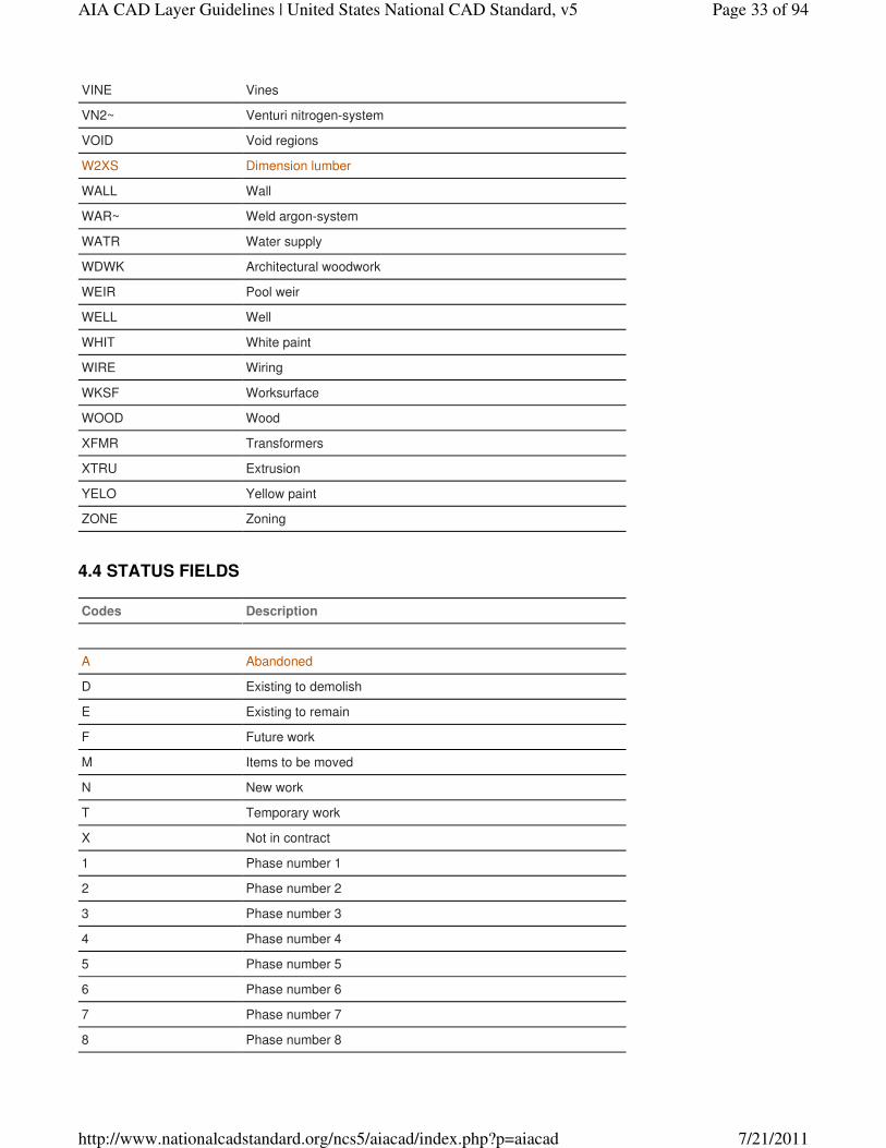
VINE Vines
VN2~ Venturi nitrogen-system
VOID Void regions
W2XS Dimension lumber
WALL Wall
WAR~ Weld argon-system
WATR Water supply
WDWK Architectural woodwork
WEIR Pool weir
WELL Well
WHIT White paint
WIRE Wiring
WKSF Worksurface
WOOD Wood
XFMR Transformers
XTRU Extrusion
YELO Yellow paint
ZONE Zoning
Codes Description
A Abandoned
D Existing to demolish
E Existing to remain
F Future work
M Items to be moved
N New work
T Temporary work
X Not in contract
1 Phase number 1
2 Phase number 2
3 Phase number 3
4 Phase number 4
5 Phase number 5
6 Phase number 6
7 Phase number 7
8 Phase number 8
4.4 STATUS FIELDS
Page 33 of 94AIA CAD Layer Guidelines | United States National CAD Standard, v5
7/21/2011http://www.nationalcadstandard.org/ncs5/aiacad/index.php?p=aiacad
9 Phase number 9
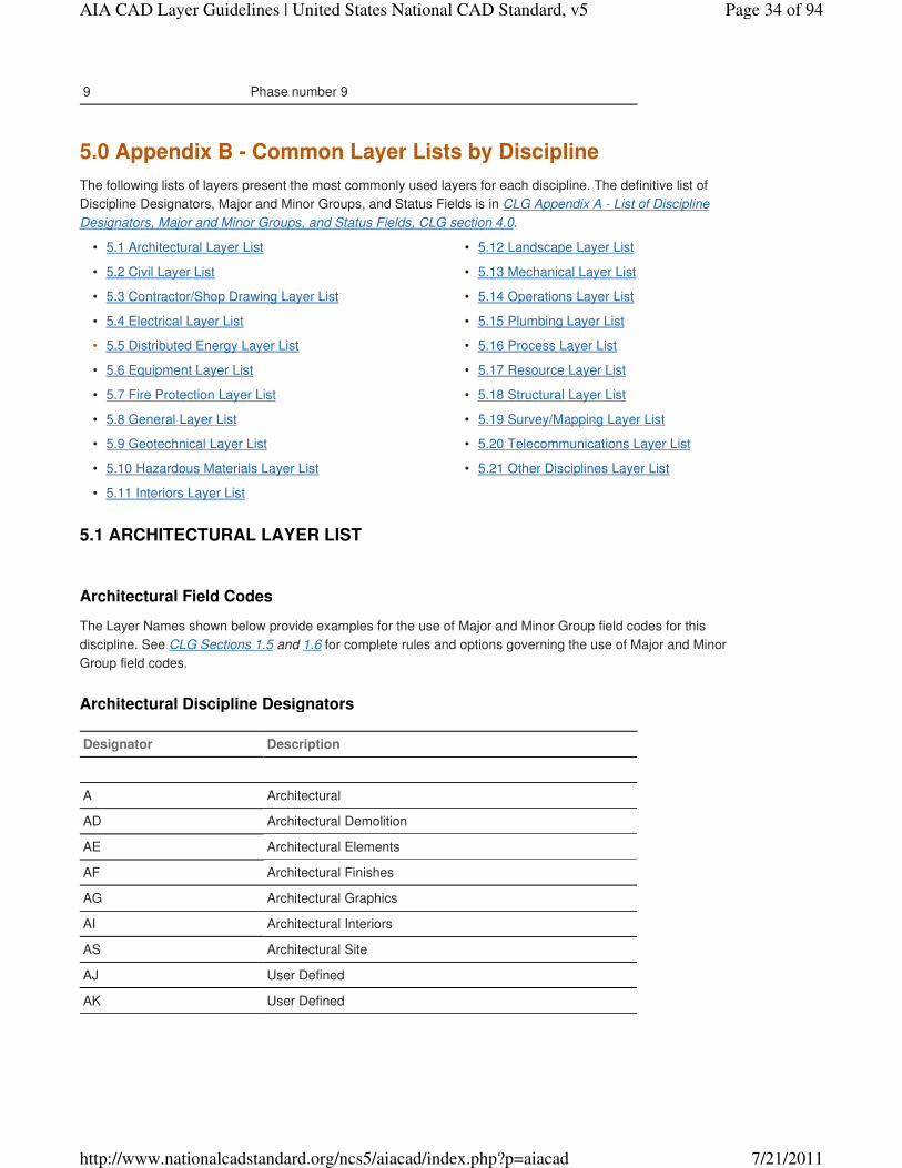
The following lists of layers present the most commonly used layers for each discipline. The definitive list of
Discipline Designators, Major and Minor Groups, and Status Fields is in CLG Appendix A - List of Discipline
Designators, Major and Minor Groups, and Status Fields, CLG section 4.0.
5.1 Architectural Layer List•
5.2 Civil Layer List•
5.3 Contractor/Shop Drawing Layer List•
5.4 Electrical Layer List•
5.5 Distributed Energy Layer List•
5.6 Equipment Layer List•
5.7 Fire Protection Layer List•
5.8 General Layer List•
5.9 Geotechnical Layer List•
5.10 Hazardous Materials Layer List•
5.11 Interiors Layer List•
5.12 Landscape Layer List•
5.13 Mechanical Layer List•
5.14 Operations Layer List•
5.15 Plumbing Layer List•
5.16 Process Layer List•
5.17 Resource Layer List•
5.18 Structural Layer List•
5.19 Survey/Mapping Layer List•
5.20 Telecommunications Layer List•
5.21 Other Disciplines Layer List•
Architectural Field Codes
The Layer Names shown below provide examples for the use of Major and Minor Group field codes for this
discipline. See CLG Sections 1.5 and 1.6 for complete rules and options governing the use of Major and Minor
Group field codes.
Architectural Discipline Designators
Designator Description
A Architectural
AD Architectural Demolition
AE Architectural Elements
AF Architectural Finishes
AG Architectural Graphics
AI Architectural Interiors
AS Architectural Site
AJ User Defined
AK User Defined
5.0 Appendix B - Common Layer Lists by Discipline
5.1 ARCHITECTURAL LAYER LIST
Page 34 of 94AIA CAD Layer Guidelines | United States National CAD Standard, v5
7/21/2011http://www.nationalcadstandard.org/ncs5/aiacad/index.php?p=aiacad
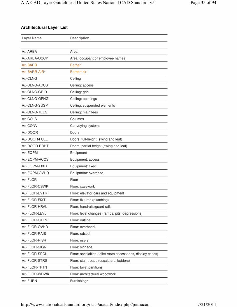
Architectural Layer List
Layer Name Description
A□-AREA Area
A□-AREA-OCCP Area: occupant or employee names
A□-BARR Barrier
A□-BARR-AIR~ Barrier: air
A□-CLNG Ceiling
A□-CLNG-ACCS Ceiling: access
A□-CLNG-GRID Ceiling: grid
A□-CLNG-OPNG Ceiling: openings
A□-CLNG-SUSP Ceiling: suspended elements
A□-CLNG-TEES Ceiling: main tees
A□-COLS Columns
A□-CONV Conveying systems
A□-DOOR Doors
A□-DOOR-FULL Doors: full-height (swing and leaf)
A□-DOOR-PRHT Doors: partial-height (swing and leaf)
A□-EQPM Equipment
A□-EQPM-ACCS Equipment: access
A□-EQPM-FIXD Equipment: fixed
A□-EQPM-OVHD Equipment: overhead
A□-FLOR Floor
A□-FLOR-CSWK Floor: casework
A□-FLOR-EVTR Floor: elevator cars and equipment
A□-FLOR-FIXT Floor: fixtures (plumbing)
A□-FLOR-HRAL Floor: handrails/guard rails
A□-FLOR-LEVL Floor: level changes (ramps, pits, depressions)
A□-FLOR-OTLN Floor: outline
A□-FLOR-OVHD Floor: overhead
A□-FLOR-RAIS Floor: raised
A□-FLOR-RISR Floor: risers
A□-FLOR-SIGN Floor: signage
A□-FLOR-SPCL Floor: specialties (toilet room accessories, display cases)
A□-FLOR-STRS Floor: stair treads (escalators, ladders)
A□-FLOR-TPTN Floor: toilet partitions
A□-FLOR-WDWK Floor: architectural woodwork
A□-FURN Furnishings
Page 35 of 94AIA CAD Layer Guidelines | United States National CAD Standard, v5
7/21/2011http://www.nationalcadstandard.org/ncs5/aiacad/index.php?p=aiacad
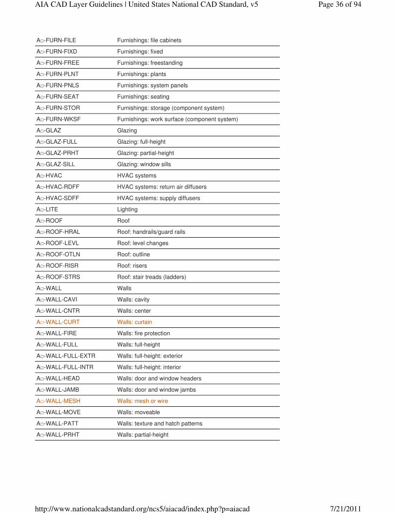
A□-FURN-FILE Furnishings: file cabinets
A□-FURN-FIXD Furnishings: fixed
A□-FURN-FREE Furnishings: freestanding
A□-FURN-PLNT Furnishings: plants
A□-FURN-PNLS Furnishings: system panels
A□-FURN-SEAT Furnishings: seating
A□-FURN-STOR Furnishings: storage (component system)
A□-FURN-WKSF Furnishings: work surface (component system)
A□-GLAZ Glazing
A□-GLAZ-FULL Glazing: full-height
A□-GLAZ-PRHT Glazing: partial-height
A□-GLAZ-SILL Glazing: window sills
A□-HVAC HVAC systems
A□-HVAC-RDFF HVAC systems: return air diffusers
A□-HVAC-SDFF HVAC systems: supply diffusers
A□-LITE Lighting
A□-ROOF Roof
A□-ROOF-HRAL Roof: handrails/guard rails
A□-ROOF-LEVL Roof: level changes
A□-ROOF-OTLN Roof: outline
A□-ROOF-RISR Roof: risers
A□-ROOF-STRS Roof: stair treads (ladders)
A□-WALL Walls
A□-WALL-CAVI Walls: cavity
A□-WALL-CNTR Walls: center
A□-WALL-CURT Walls: curtain
A□-WALL-FIRE Walls: fire protection
A□-WALL-FULL Walls: full-height
A□-WALL-FULL-EXTR Walls: full-height: exterior
A□-WALL-FULL-INTR Walls: full-height: interior
A□-WALL-HEAD Walls: door and window headers
A□-WALL-JAMB Walls: door and window jambs
A□-WALL-MESH Walls: mesh or wire
A□-WALL-MOVE Walls: moveable
A□-WALL-PATT Walls: texture and hatch patterns
A□-WALL-PRHT Walls: partial-height
Page 36 of 94AIA CAD Layer Guidelines | United States National CAD Standard, v5
7/21/2011http://www.nationalcadstandard.org/ncs5/aiacad/index.php?p=aiacad
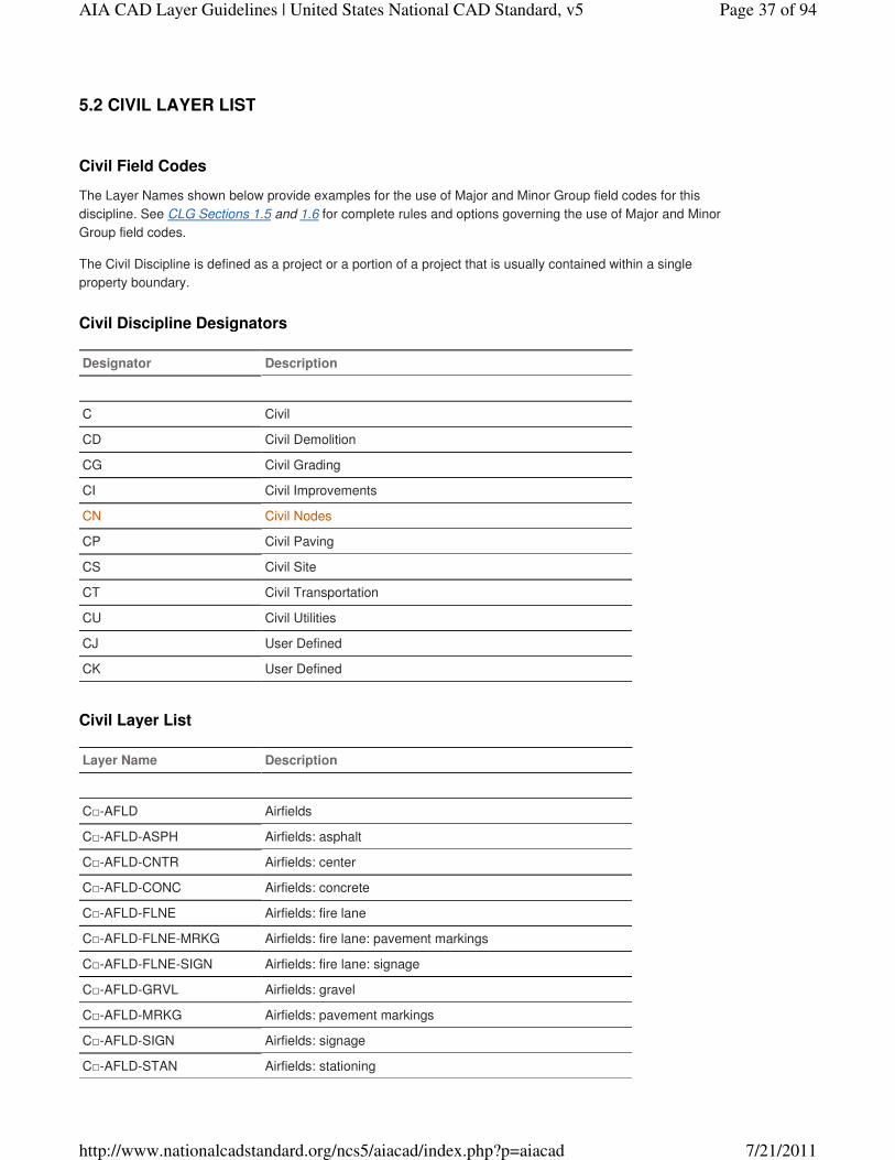
Civil Field Codes
The Layer Names shown below provide examples for the use of Major and Minor Group field codes for this
discipline. See CLG Sections 1.5 and 1.6 for complete rules and options governing the use of Major and Minor
Group field codes.
The Civil Discipline is defined as a project or a portion of a project that is usually contained within a single
property boundary.
Civil Discipline Designators
Designator Description
C Civil
CD Civil Demolition
CG Civil Grading
CI Civil Improvements
CN Civil Nodes
CP Civil Paving
CS Civil Site
CT Civil Transportation
CU Civil Utilities
CJ User Defined
CK User Defined
Civil Layer List
Layer Name Description
C□-AFLD Airfields
C□-AFLD-ASPH Airfields: asphalt
C□-AFLD-CNTR Airfields: center
C□-AFLD-CONC Airfields: concrete
C□-AFLD-FLNE Airfields: fire lane
C□-AFLD-FLNE-MRKG Airfields: fire lane: pavement markings
C□-AFLD-FLNE-SIGN Airfields: fire lane: signage
C□-AFLD-GRVL Airfields: gravel
C□-AFLD-MRKG Airfields: pavement markings
C□-AFLD-SIGN Airfields: signage
C□-AFLD-STAN Airfields: stationing
5.2 CIVIL LAYER LIST
Page 37 of 94AIA CAD Layer Guidelines | United States National CAD Standard, v5
7/21/2011http://www.nationalcadstandard.org/ncs5/aiacad/index.php?p=aiacad
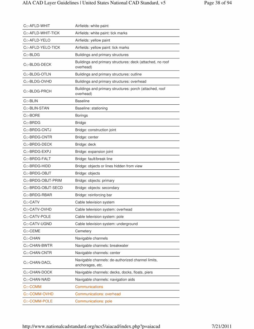
C□-AFLD-WHIT Airfields: white paint
C□-AFLD-WHIT-TICK Airfields: white paint: tick marks
C□-AFLD-YELO Airfields: yellow paint
C□-AFLD-YELO-TICK Airfields: yellow paint: tick marks
C□-BLDG Buildings and primary structures
C□-BLDG-DECKBuildings and primary structures: deck (attached, no roof
overhead)
C□-BLDG-OTLN Buildings and primary structures: outline
C□-BLDG-OVHD Buildings and primary structures: overhead
C□-BLDG-PRCHBuildings and primary structures: porch (attached, roof
overhead)
C□-BLIN Baseline
C□-BLIN-STAN Baseline: stationing
C□-BORE Borings
C□-BRDG Bridge
C□-BRDG-CNTJ Bridge: construction joint
C□-BRDG-CNTR Bridge: center
C□-BRDG-DECK Bridge: deck
C□-BRDG-EXPJ Bridge: expansion joint
C□-BRDG-FALT Bridge: fault/break line
C□-BRDG-HIDD Bridge: objects or lines hidden from view
C□-BRDG-OBJT Bridge: objects
C□-BRDG-OBJT-PRIM Bridge: objects: primary
C□-BRDG-OBJT-SECD Bridge: objects: secondary
C□-BRDG-RBAR Bridge: reinforcing bar
C□-CATV Cable television system
C□-CATV-OVHD Cable television system: overhead
C□-CATV-POLE Cable television system: pole
C□-CATV-UGND Cable television system: underground
C□-CEME Cemetery
C□-CHAN Navigable channels
C□-CHAN-BWTR Navigable channels: breakwater
C□-CHAN-CNTR Navigable channels: center
C□-CHAN-DACLNavigable channels: de-authorized channel limits,
anchorages, etc.
C□-CHAN-DOCK Navigable channels: decks, docks, floats, piers
C□-CHAN-NAID Navigable channels: navigation aids
C□-COMM Communications
C□-COMM-OVHD Communications: overhead
C□-COMM-POLE Communications: pole
Page 38 of 94AIA CAD Layer Guidelines | United States National CAD Standard, v5
7/21/2011http://www.nationalcadstandard.org/ncs5/aiacad/index.php?p=aiacad
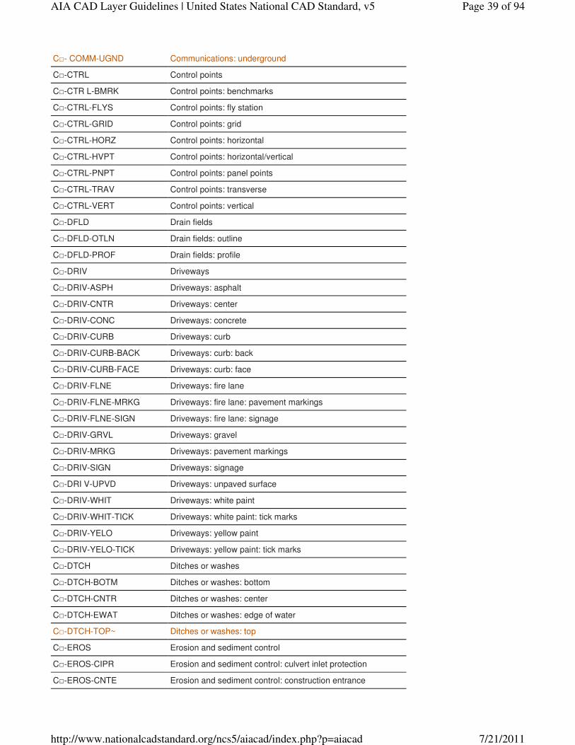
C□- COMM-UGND Communications: underground
C□-CTRL Control points
C□-CTR L-BMRK Control points: benchmarks
C□-CTRL-FLYS Control points: fly station
C□-CTRL-GRID Control points: grid
C□-CTRL-HORZ Control points: horizontal
C□-CTRL-HVPT Control points: horizontal/vertical
C□-CTRL-PNPT Control points: panel points
C□-CTRL-TRAV Control points: transverse
C□-CTRL-VERT Control points: vertical
C□-DFLD Drain fields
C□-DFLD-OTLN Drain fields: outline
C□-DFLD-PROF Drain fields: profile
C□-DRIV Driveways
C□-DRIV-ASPH Driveways: asphalt
C□-DRIV-CNTR Driveways: center
C□-DRIV-CONC Driveways: concrete
C□-DRIV-CURB Driveways: curb
C□-DRIV-CURB-BACK Driveways: curb: back
C□-DRIV-CURB-FACE Driveways: curb: face
C□-DRIV-FLNE Driveways: fire lane
C□-DRIV-FLNE-MRKG Driveways: fire lane: pavement markings
C□-DRIV-FLNE-SIGN Driveways: fire lane: signage
C□-DRIV-GRVL Driveways: gravel
C□-DRIV-MRKG Driveways: pavement markings
C□-DRIV-SIGN Driveways: signage
C□-DRI V-UPVD Driveways: unpaved surface
C□-DRIV-WHIT Driveways: white paint
C□-DRIV-WHIT-TICK Driveways: white paint: tick marks
C□-DRIV-YELO Driveways: yellow paint
C□-DRIV-YELO-TICK Driveways: yellow paint: tick marks
C□-DTCH Ditches or washes
C□-DTCH-BOTM Ditches or washes: bottom
C□-DTCH-CNTR Ditches or washes: center
C□-DTCH-EWAT Ditches or washes: edge of water
C□-DTCH-TOP~ Ditches or washes: top
C□-EROS Erosion and sediment control
C□-EROS-CIPR Erosion and sediment control: culvert inlet protection
C□-EROS-CNTE Erosion and sediment control: construction entrance
Page 39 of 94AIA CAD Layer Guidelines | United States National CAD Standard, v5
7/21/2011http://www.nationalcadstandard.org/ncs5/aiacad/index.php?p=aiacad
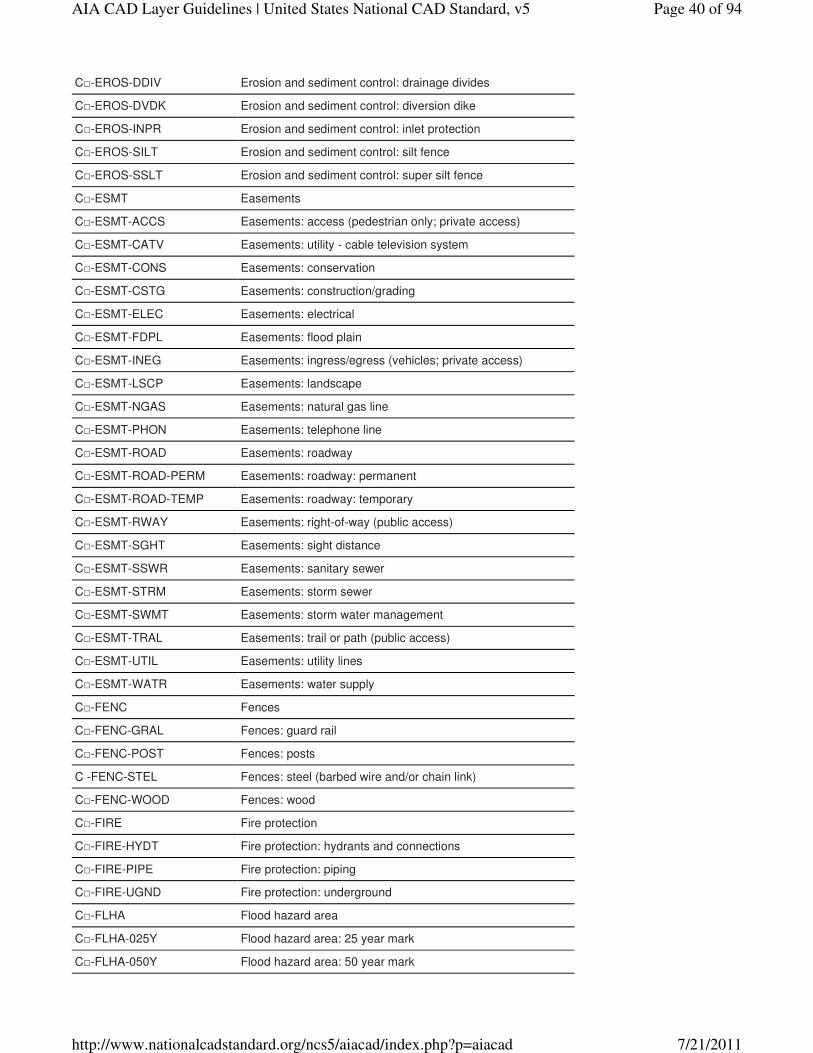
C□-EROS-DDIV Erosion and sediment control: drainage divides
C□-EROS-DVDK Erosion and sediment control: diversion dike
C□-EROS-INPR Erosion and sediment control: inlet protection
C□-EROS-SILT Erosion and sediment control: silt fence
C□-EROS-SSLT Erosion and sediment control: super silt fence
C□-ESMT Easements
C□-ESMT-ACCS Easements: access (pedestrian only; private access)
C□-ESMT-CATV Easements: utility - cable television system
C□-ESMT-CONS Easements: conservation
C□-ESMT-CSTG Easements: construction/grading
C□-ESMT-ELEC Easements: electrical
C□-ESMT-FDPL Easements: flood plain
C□-ESMT-INEG Easements: ingress/egress (vehicles; private access)
C□-ESMT-LSCP Easements: landscape
C□-ESMT-NGAS Easements: natural gas line
C□-ESMT-PHON Easements: telephone line
C□-ESMT-ROAD Easements: roadway
C□-ESMT-ROAD-PERM Easements: roadway: permanent
C□-ESMT-ROAD-TEMP Easements: roadway: temporary
C□-ESMT-RWAY Easements: right-of-way (public access)
C□-ESMT-SGHT Easements: sight distance
C□-ESMT-SSWR Easements: sanitary sewer
C□-ESMT-STRM Easements: storm sewer
C□-ESMT-SWMT Easements: storm water management
C□-ESMT-TRAL Easements: trail or path (public access)
C□-ESMT-UTIL Easements: utility lines
C□-ESMT-WATR Easements: water supply
C□-FENC Fences
C□-FENC-GRAL Fences: guard rail
C□-FENC-POST Fences: posts
C -FENC-STEL Fences: steel (barbed wire and/or chain link)
C□-FENC-WOOD Fences: wood
C□-FIRE Fire protection
C□-FIRE-HYDT Fire protection: hydrants and connections
C□-FIRE-PIPE Fire protection: piping
C□-FIRE-UGND Fire protection: underground
C□-FLHA Flood hazard area
C□-FLHA-025Y Flood hazard area: 25 year mark
C□-FLHA-050Y Flood hazard area: 50 year mark
Page 40 of 94AIA CAD Layer Guidelines | United States National CAD Standard, v5
7/21/2011http://www.nationalcadstandard.org/ncs5/aiacad/index.php?p=aiacad
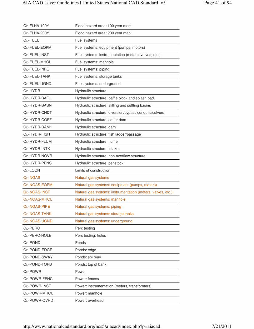
C□-FLHA-100Y Flood hazard area: 100 year mark
C□-FLHA-200Y Flood hazard area: 200 year mark
C□-FUEL Fuel systems
C□-FUEL-EQPM Fuel systems: equipment (pumps, motors)
C□-FUEL-INST Fuel systems: instrumentation (meters, valves, etc.)
C□-FUEL-MHOL Fuel systems: manhole
C□-FUEL-PIPE Fuel systems: piping
C□-FUEL-TANK Fuel systems: storage tanks
C□-FUEL-UGND Fuel systems: underground
C□-HYDR Hydraulic structure
C□-HYDR-BAFL Hydraulic structure: baffle block and splash pad
C□-HYDR-BASN Hydraulic structure: stilling and settling basins
C□-HYDR-CNDT Hydraulic structure: diversion/bypass conduits/culvers
C□-HYDR-COFF Hydraulic structure: coffer dam
C□-HYDR-DAM~ Hydraulic structure: dam
C□-HYDR-FISH Hydraulic structure: fish ladder/passage
C□-HYDR-FLUM Hydraulic structure: flume
C□-HYDR-INTK Hydraulic structure: intake
C□-HYDR-NOVR Hydraulic structure: non-overflow structure
C□-HYDR-PENS Hydraulic structure: penstock
C□-LOCN Limits of construction
C□-NGAS Natural gas systems
C□-NGAS-EQPM Natural gas systems: equipment (pumps, motors)
C□-NGAS-INST Natural gas systems: instrumentation (meters, valves, etc.)
C□-NGAS-MHOL Natural gas systems: manhole
C□-NGAS-PIPE Natural gas systems: piping
C□-NGAS-TANK Natural gas systems: storage tanks
C□-NGAS-UGND Natural gas systems: underground
C□-PERC Perc testing
C□-PERC-HOLE Perc testing: holes
C□-POND Ponds
C□-POND-EDGE Ponds: edge
C□-POND-SWAY Ponds: spillway
C□-POND-TOPB Ponds: top of bank
C□-POWR Power
C□-POWR-FENC Power: fences
C□-POWR-INST Power: instrumentation (meters, transformers)
C□-POWR-MHOL Power: manhole
C□-POWR-OVHD Power: overhead
Page 41 of 94AIA CAD Layer Guidelines | United States National CAD Standard, v5
7/21/2011http://www.nationalcadstandard.org/ncs5/aiacad/index.php?p=aiacad
C□-POWR-POLE Power: pole
C□-POWR-STRC Power: structures
C□-POWR-UGND Power: underground
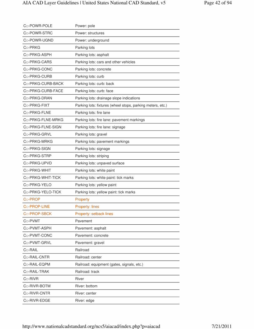
C□-PRKG Parking lots
C□-PRKG-ASPH Parking lots: asphalt
C□-PRKG-CARS Parking lots: cars and other vehicles
C□-PRKG-CONC Parking lots: concrete
C□-PRKG-CURB Parking lots: curb
C□-PRKG-CURB-BACK Parking lots: curb: back
C□-PRKG-CURB-FACE Parking lots: curb: face
C□-PRKG-DRAN Parking lots: drainage slope indications
C□-PRKG-FIXT Parking lots: fixtures (wheel stops, parking meters, etc.)
C□-PRKG-FLNE Parking lots: fire lane
C□-PRKG-FLNE-MRKG Parking lots: fire lane: pavement markings
C□-PRKG-FLNE-SIGN Parking lots: fire lane: signage
C□-PRKG-GRVL Parking lots: gravel
C□-PRKG-MRKG Parking lots: pavement markings
C□-PRKG-SIGN Parking lots: signage
C□-PRKG-STRP Parking lots: striping
C□-PRKG-UPVD Parking lots: unpaved surface
C□-PRKG-WHIT Parking lots: white paint
C□-PRKG-WHIT-TICK Parking lots: white paint: tick marks
C□-PRKG-YELO Parking lots: yellow paint
C□-PRKG-YELO-TICK Parking lots: yellow paint: tick marks
C□-PROP Property
C□-PROP-LINE Property: lines
C□-PROP-SBCK Property: setback lines
C□-PVMT Pavement
C□-PVMT-ASPH Pavement: asphalt
C□-PVMT-CONC Pavement: concrete
C□-PVMT-GRVL Pavement: gravel
C□-RAIL Railroad
C□-RAIL-CNTR Railroad: center
C□-RAIL-EQPM Railroad: equipment (gates, signals, etc.)
C□-RAIL-TRAK Railroad: track
C□-RIVR River
C□-RIVR-BOTM River: bottom
C□-RIVR-CNTR River: center
C□-RIVR-EDGE River: edge
Page 42 of 94AIA CAD Layer Guidelines | United States National CAD Standard, v5
7/21/2011http://www.nationalcadstandard.org/ncs5/aiacad/index.php?p=aiacad
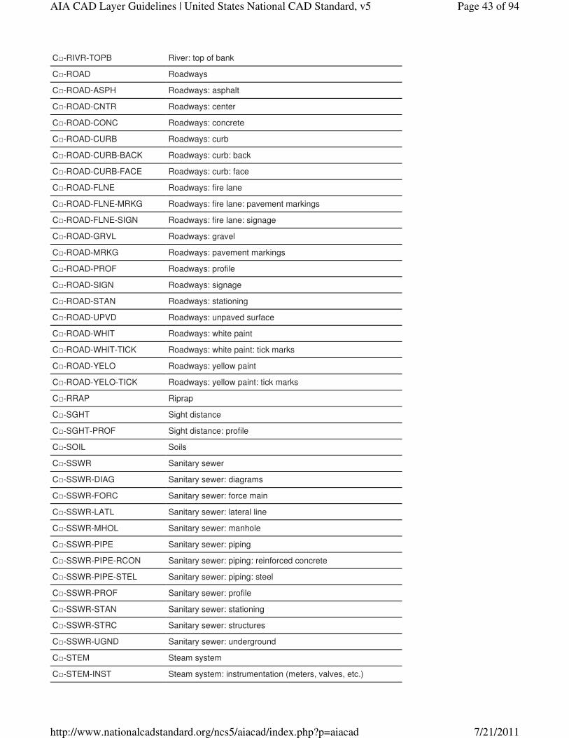
C□-RIVR-TOPB River: top of bank
C□-ROAD Roadways
C□-ROAD-ASPH Roadways: asphalt
C□-ROAD-CNTR Roadways: center
C□-ROAD-CONC Roadways: concrete
C□-ROAD-CURB Roadways: curb
C□-ROAD-CURB-BACK Roadways: curb: back
C□-ROAD-CURB-FACE Roadways: curb: face
C□-ROAD-FLNE Roadways: fire lane
C□-ROAD-FLNE-MRKG Roadways: fire lane: pavement markings
C□-ROAD-FLNE-SIGN Roadways: fire lane: signage
C□-ROAD-GRVL Roadways: gravel
C□-ROAD-MRKG Roadways: pavement markings
C□-ROAD-PROF Roadways: profile
C□-ROAD-SIGN Roadways: signage
C□-ROAD-STAN Roadways: stationing
C□-ROAD-UPVD Roadways: unpaved surface
C□-ROAD-WHIT Roadways: white paint
C□-ROAD-WHIT-TICK Roadways: white paint: tick marks
C□-ROAD-YELO Roadways: yellow paint
C□-ROAD-YELO-TICK Roadways: yellow paint: tick marks
C□-RRAP Riprap
C□-SGHT Sight distance
C□-SGHT-PROF Sight distance: profile
C□-SOIL Soils
C□-SSWR Sanitary sewer
C□-SSWR-DIAG Sanitary sewer: diagrams
C□-SSWR-FORC Sanitary sewer: force main
C□-SSWR-LATL Sanitary sewer: lateral line
C□-SSWR-MHOL Sanitary sewer: manhole
C□-SSWR-PIPE Sanitary sewer: piping
C□-SSWR-PIPE-RCON Sanitary sewer: piping: reinforced concrete
C□-SSWR-PIPE-STEL Sanitary sewer: piping: steel
C□-SSWR-PROF Sanitary sewer: profile
C□-SSWR-STAN Sanitary sewer: stationing
C□-SSWR-STRC Sanitary sewer: structures
C□-SSWR-UGND Sanitary sewer: underground
C□-STEM Steam system
C□-STEM-INST Steam system: instrumentation (meters, valves, etc.)
Page 43 of 94AIA CAD Layer Guidelines | United States National CAD Standard, v5
7/21/2011http://www.nationalcadstandard.org/ncs5/aiacad/index.php?p=aiacad
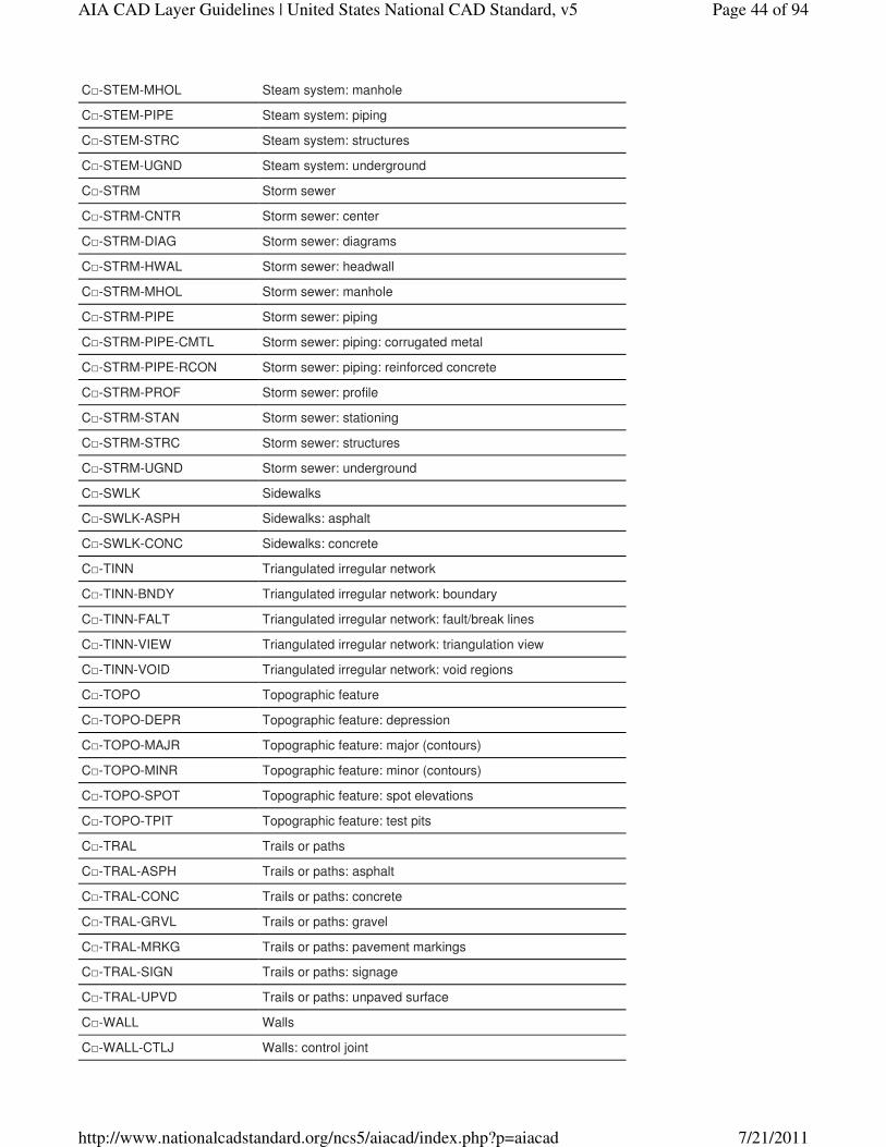
C□-STEM-MHOL Steam system: manhole
C□-STEM-PIPE Steam system: piping
C□-STEM-STRC Steam system: structures
C□-STEM-UGND Steam system: underground
C□-STRM Storm sewer
C□-STRM-CNTR Storm sewer: center
C□-STRM-DIAG Storm sewer: diagrams
C□-STRM-HWAL Storm sewer: headwall
C□-STRM-MHOL Storm sewer: manhole
C□-STRM-PIPE Storm sewer: piping
C□-STRM-PIPE-CMTL Storm sewer: piping: corrugated metal
C□-STRM-PIPE-RCON Storm sewer: piping: reinforced concrete
C□-STRM-PROF Storm sewer: profile
C□-STRM-STAN Storm sewer: stationing
C□-STRM-STRC Storm sewer: structures
C□-STRM-UGND Storm sewer: underground
C□-SWLK Sidewalks
C□-SWLK-ASPH Sidewalks: asphalt
C□-SWLK-CONC Sidewalks: concrete
C□-TINN Triangulated irregular network
C□-TINN-BNDY Triangulated irregular network: boundary
C□-TINN-FALT Triangulated irregular network: fault/break lines
C□-TINN-VIEW Triangulated irregular network: triangulation view
C□-TINN-VOID Triangulated irregular network: void regions
C□-TOPO Topographic feature
C□-TOPO-DEPR Topographic feature: depression
C□-TOPO-MAJR Topographic feature: major (contours)
C□-TOPO-MINR Topographic feature: minor (contours)
C□-TOPO-SPOT Topographic feature: spot elevations
C□-TOPO-TPIT Topographic feature: test pits
C□-TRAL Trails or paths
C□-TRAL-ASPH Trails or paths: asphalt
C□-TRAL-CONC Trails or paths: concrete
C□-TRAL-GRVL Trails or paths: gravel
C□-TRAL-MRKG Trails or paths: pavement markings
C□-TRAL-SIGN Trails or paths: signage
C□-TRAL-UPVD Trails or paths: unpaved surface
C□-WALL Walls
C□-WALL-CTLJ Walls: control joint
Page 44 of 94AIA CAD Layer Guidelines | United States National CAD Standard, v5
7/21/2011http://www.nationalcadstandard.org/ncs5/aiacad/index.php?p=aiacad
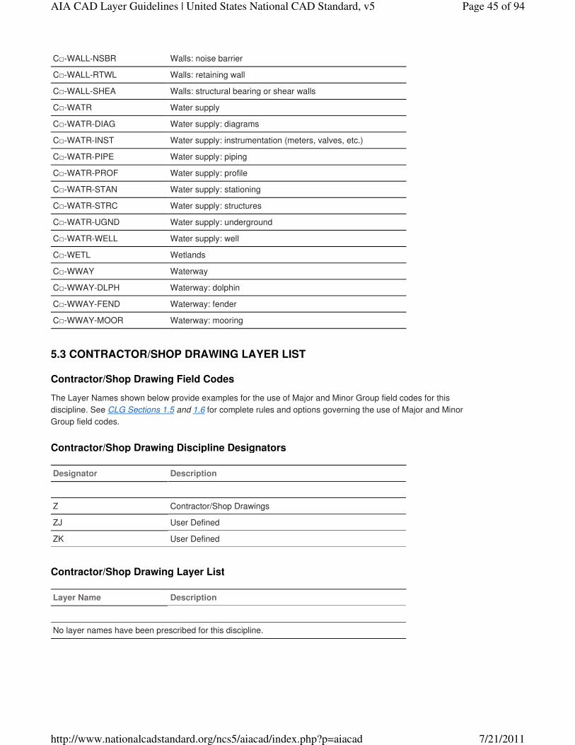
C□-WALL-NSBR Walls: noise barrier
C□-WALL-RTWL Walls: retaining wall
C□-WALL-SHEA Walls: structural bearing or shear walls
C□-WATR Water supply
C□-WATR-DIAG Water supply: diagrams
C□-WATR-INST Water supply: instrumentation (meters, valves, etc.)
C□-WATR-PIPE Water supply: piping
C□-WATR-PROF Water supply: profile
C□-WATR-STAN Water supply: stationing
C□-WATR-STRC Water supply: structures
C□-WATR-UGND Water supply: underground
C□-WATR-WELL Water supply: well
C□-WETL Wetlands
C□-WWAY Waterway
C□-WWAY-DLPH Waterway: dolphin
C□-WWAY-FEND Waterway: fender
C□-WWAY-MOOR Waterway: mooring
Contractor/Shop Drawing Field Codes
The Layer Names shown below provide examples for the use of Major and Minor Group field codes for this
discipline. See CLG Sections 1.5 and 1.6 for complete rules and options governing the use of Major and Minor
Group field codes.
Contractor/Shop Drawing Discipline Designators
Designator Description
Z Contractor/Shop Drawings
ZJ User Defined
ZK User Defined
Contractor/Shop Drawing Layer List
Layer Name Description
No layer names have been prescribed for this discipline.
5.3 CONTRACTOR/SHOP DRAWING LAYER LIST
Page 45 of 94AIA CAD Layer Guidelines | United States National CAD Standard, v5
7/21/2011http://www.nationalcadstandard.org/ncs5/aiacad/index.php?p=aiacad
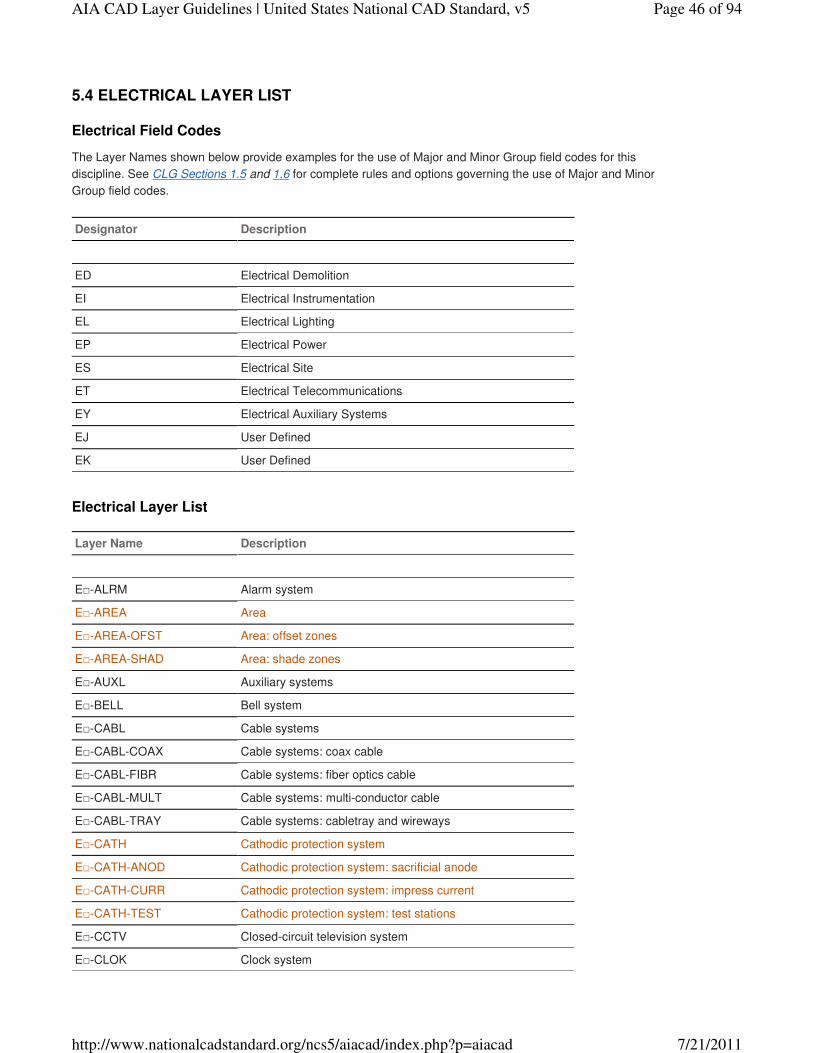
Electrical Field Codes
The Layer Names shown below provide examples for the use of Major and Minor Group field codes for this
discipline. See CLG Sections 1.5 and 1.6 for complete rules and options governing the use of Major and Minor
Group field codes.
Designator Description
ED Electrical Demolition
EI Electrical Instrumentation
EL Electrical Lighting
EP Electrical Power
ES Electrical Site
ET Electrical Telecommunications
EY Electrical Auxiliary Systems
EJ User Defined
EK User Defined
Electrical Layer List
Layer Name Description
E□-ALRM Alarm system
E□-AREA Area
E□-AREA-OFST Area: offset zones
E□-AREA-SHAD Area: shade zones
E□-AUXL Auxiliary systems
E□-BELL Bell system
E□-CABL Cable systems
E□-CABL-COAX Cable systems: coax cable
E□-CABL-FIBR Cable systems: fiber optics cable
E□-CABL-MULT Cable systems: multi-conductor cable
E□-CABL-TRAY Cable systems: cabletray and wireways
E□-CATH Cathodic protection system
E□-CATH-ANOD Cathodic protection system: sacrificial anode
E□-CATH-CURR Cathodic protection system: impress current
E□-CATH-TEST Cathodic protection system: test stations
E□-CCTV Closed-circuit television system
E□-CLOK Clock system
5.4 ELECTRICAL LAYER LIST
Page 46 of 94AIA CAD Layer Guidelines | United States National CAD Standard, v5
7/21/2011http://www.nationalcadstandard.org/ncs5/aiacad/index.php?p=aiacad
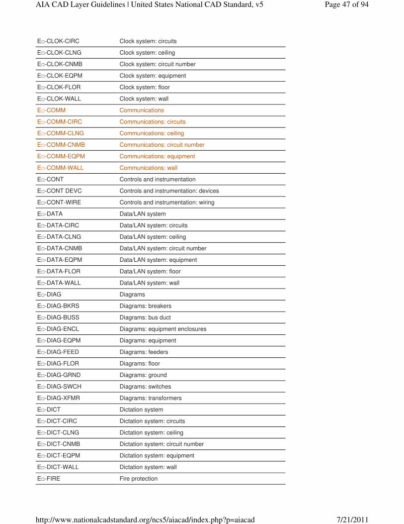
E□-CLOK-CIRC Clock system: circuits
E□-CLOK-CLNG Clock system: ceiling
E□-CLOK-CNMB Clock system: circuit number
E□-CLOK-EQPM Clock system: equipment
E□-CLOK-FLOR Clock system: floor
E□-CLOK-WALL Clock system: wall
E□-COMM Communications
E□-COMM-CIRC Communications: circuits
E□-COMM-CLNG Communications: ceiling
E□-COMM-CNMB Communications: circuit number
E□-COMM-EQPM Communications: equipment
E□-COMM-WALL Communications: wall
E□-CONT Controls and instrumentation
E□-CONT DEVC Controls and instrumentation: devices
E□-CONT-WIRE Controls and instrumentation: wiring
E□-DATA Data/LAN system
E□-DATA-CIRC Data/LAN system: circuits
E□-DATA-CLNG Data/LAN system: ceiling
E□-DATA-CNMB Data/LAN system: circuit number
E□-DATA-EQPM Data/LAN system: equipment
E□-DATA-FLOR Data/LAN system: floor
E□-DATA-WALL Data/LAN system: wall
E□-DIAG Diagrams
E□-DIAG-BKRS Diagrams: breakers
E□-DIAG-BUSS Diagrams: bus duct
E□-DIAG-ENCL Diagrams: equipment enclosures
E□-DIAG-EQPM Diagrams: equipment
E□-DIAG-FEED Diagrams: feeders
E□-DIAG-FLOR Diagrams: floor
E□-DIAG-GRND Diagrams: ground
E□-DIAG-SWCH Diagrams: switches
E□-DIAG-XFMR Diagrams: transformers
E□-DICT Dictation system
E□-DICT-CIRC Dictation system: circuits
E□-DICT-CLNG Dictation system: ceiling
E□-DICT-CNMB Dictation system: circuit number
E□-DICT-EQPM Dictation system: equipment
E□-DICT-WALL Dictation system: wall
E□-FIRE Fire protection
Page 47 of 94AIA CAD Layer Guidelines | United States National CAD Standard, v5
7/21/2011http://www.nationalcadstandard.org/ncs5/aiacad/index.php?p=aiacad
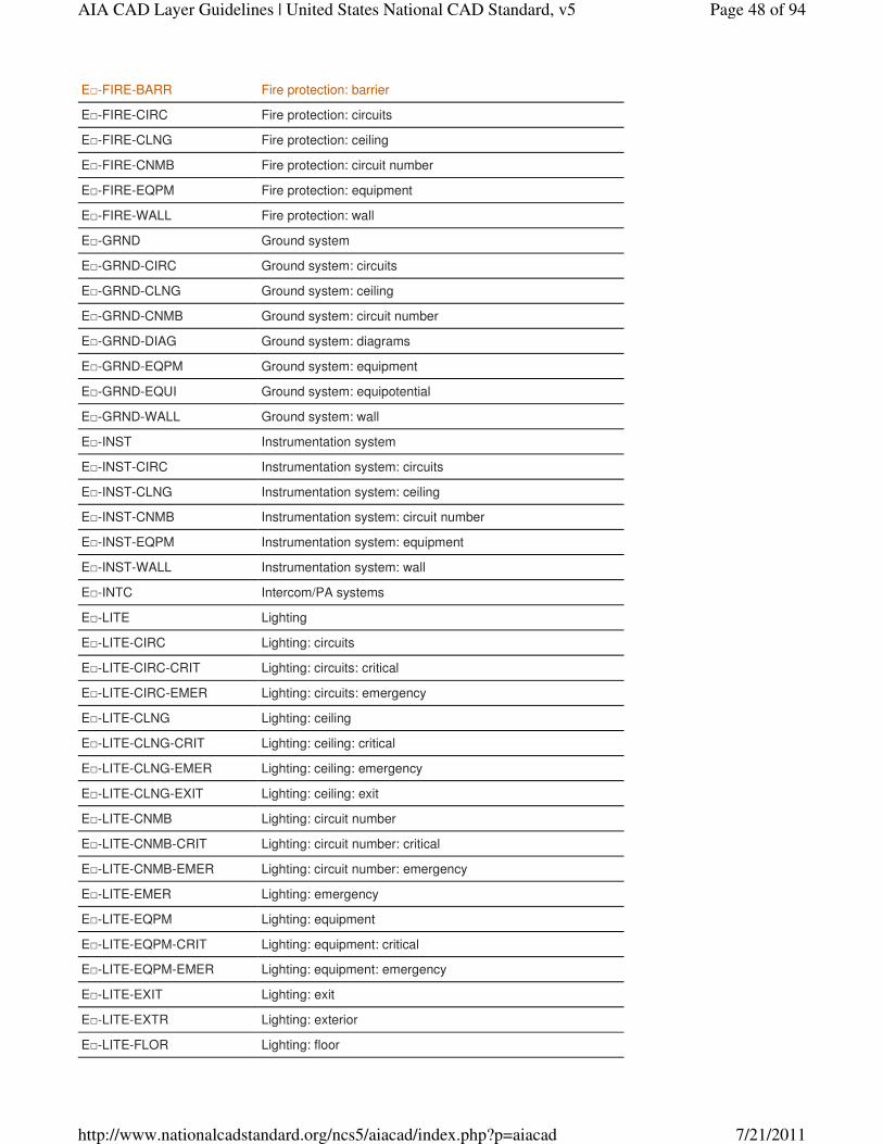
E□-FIRE-BARR Fire protection: barrier
E□-FIRE-CIRC Fire protection: circuits
E□-FIRE-CLNG Fire protection: ceiling
E□-FIRE-CNMB Fire protection: circuit number
E□-FIRE-EQPM Fire protection: equipment
E□-FIRE-WALL Fire protection: wall
E□-GRND Ground system
E□-GRND-CIRC Ground system: circuits
E□-GRND-CLNG Ground system: ceiling
E□-GRND-CNMB Ground system: circuit number
E□-GRND-DIAG Ground system: diagrams
E□-GRND-EQPM Ground system: equipment
E□-GRND-EQUI Ground system: equipotential
E□-GRND-WALL Ground system: wall
E□-INST Instrumentation system
E□-INST-CIRC Instrumentation system: circuits
E□-INST-CLNG Instrumentation system: ceiling
E□-INST-CNMB Instrumentation system: circuit number
E□-INST-EQPM Instrumentation system: equipment
E□-INST-WALL Instrumentation system: wall
E□-INTC Intercom/PA systems
E□-LITE Lighting
E□-LITE-CIRC Lighting: circuits
E□-LITE-CIRC-CRIT Lighting: circuits: critical
E□-LITE-CIRC-EMER Lighting: circuits: emergency
E□-LITE-CLNG Lighting: ceiling
E□-LITE-CLNG-CRIT Lighting: ceiling: critical
E□-LITE-CLNG-EMER Lighting: ceiling: emergency
E□-LITE-CLNG-EXIT Lighting: ceiling: exit
E□-LITE-CNMB Lighting: circuit number
E□-LITE-CNMB-CRIT Lighting: circuit number: critical
E□-LITE-CNMB-EMER Lighting: circuit number: emergency
E□-LITE-EMER Lighting: emergency
E□-LITE-EQPM Lighting: equipment
E□-LITE-EQPM-CRIT Lighting: equipment: critical
E□-LITE-EQPM-EMER Lighting: equipment: emergency
E□-LITE-EXIT Lighting: exit
E□-LITE-EXTR Lighting: exterior
E□-LITE-FLOR Lighting: floor
Page 48 of 94AIA CAD Layer Guidelines | United States National CAD Standard, v5
7/21/2011http://www.nationalcadstandard.org/ncs5/aiacad/index.php?p=aiacad
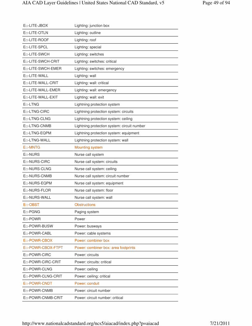
E□-LITE-JBOX Lighting: junction box
E□-LITE-OTLN Lighting: outline
E□-LITE-ROOF Lighting: roof
E□-LITE-SPCL Lighting: special
E□-LITE-SWCH Lighting: switches
E□-LITE-SWCH-CRIT Lighting: switches: critical
E□-LITE-SWCH-EMER Lighting: switches: emergency
E□-LITE-WALL Lighting: wall
E□-LITE-WALL-CRIT Lighting: wall: critical
E□-LITE-WALL-EMER Lighting: wall: emergency
E□-LITE-WALL-EXIT Lighting: wall: exit
E□-LTNG Lightning protection system
E□-LTNG-CIRC Lightning protection system: circuits
E□-LTNG-CLNG Lightning protection system: ceiling
E□-LTNG-CNMB Lightning protection system: circuit number
E□-LTNG-EQPM Lightning protection system: equipment
E□-LTNG-WALL Lightning protection system: wall
E□-MNTG Mounting system
E□-NURS Nurse call system
E□-NURS-CIRC Nurse call system: circuits
E□-NURS-CLNG Nurse call system: ceiling
E□-NURS-CNMB Nurse call system: circuit number
E□-NURS-EQPM Nurse call system: equipment
E□-NURS-FLOR Nurse call system: floor
E□-NURS-WALL Nurse call system: wall
E□-OBST Obstructions
E□-PGNG Paging system
E□-POWR Power
E□-POWR-BUSW Power: busways
E□-POWR-CABL Power: cable systems
E□-POWR-CBOX Power: combiner box
E□-POWR-CBOX-FTPT Power: combiner box: area footprints
E□-POWR-CIRC Power: circuits
E□-POWR-CIRC-CRIT Power: circuits: critical
E□-POWR-CLNG Power: ceiling
E□-POWR-CLNG-CRIT Power: ceiling: critical
E□-POWR-CNDT Power: conduit
E□-POWR-CNMB Power: circuit number
E□-POWR-CNMB-CRIT Power: circuit number: critical
Page 49 of 94AIA CAD Layer Guidelines | United States National CAD Standard, v5
7/21/2011http://www.nationalcadstandard.org/ncs5/aiacad/index.php?p=aiacad
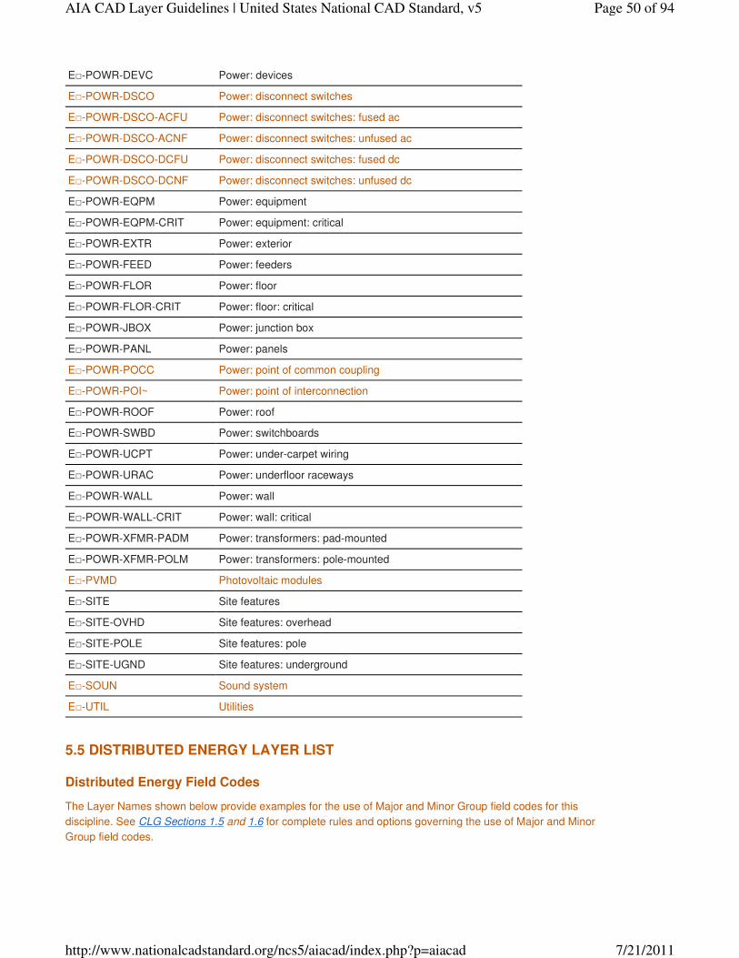
E□-POWR-DEVC Power: devices
E□-POWR-DSCO Power: disconnect switches
E□-POWR-DSCO-ACFU Power: disconnect switches: fused ac
E□-POWR-DSCO-ACNF Power: disconnect switches: unfused ac
E□-POWR-DSCO-DCFU Power: disconnect switches: fused dc
E□-POWR-DSCO-DCNF Power: disconnect switches: unfused dc
E□-POWR-EQPM Power: equipment
E□-POWR-EQPM-CRIT Power: equipment: critical
E□-POWR-EXTR Power: exterior
E□-POWR-FEED Power: feeders
E□-POWR-FLOR Power: floor
E□-POWR-FLOR-CRIT Power: floor: critical
E□-POWR-JBOX Power: junction box
E□-POWR-PANL Power: panels
E□-POWR-POCC Power: point of common coupling
E□-POWR-POI~ Power: point of interconnection
E□-POWR-ROOF Power: roof
E□-POWR-SWBD Power: switchboards
E□-POWR-UCPT Power: under-carpet wiring
E□-POWR-URAC Power: underfloor raceways
E□-POWR-WALL Power: wall
E□-POWR-WALL-CRIT Power: wall: critical
E□-POWR-XFMR-PADM Power: transformers: pad-mounted
E□-POWR-XFMR-POLM Power: transformers: pole-mounted
E□-PVMD Photovoltaic modules
E□-SITE Site features
E□-SITE-OVHD Site features: overhead
E□-SITE-POLE Site features: pole
E□-SITE-UGND Site features: underground
E□-SOUN Sound system
E□-UTIL Utilities
Distributed Energy Field Codes
The Layer Names shown below provide examples for the use of Major and Minor Group field codes for this
discipline. See CLG Sections 1.5 and 1.6 for complete rules and options governing the use of Major and Minor
Group field codes.
5.5 DISTRIBUTED ENERGY LAYER LIST
Page 50 of 94AIA CAD Layer Guidelines | United States National CAD Standard, v5
7/21/2011http://www.nationalcadstandard.org/ncs5/aiacad/index.php?p=aiacad
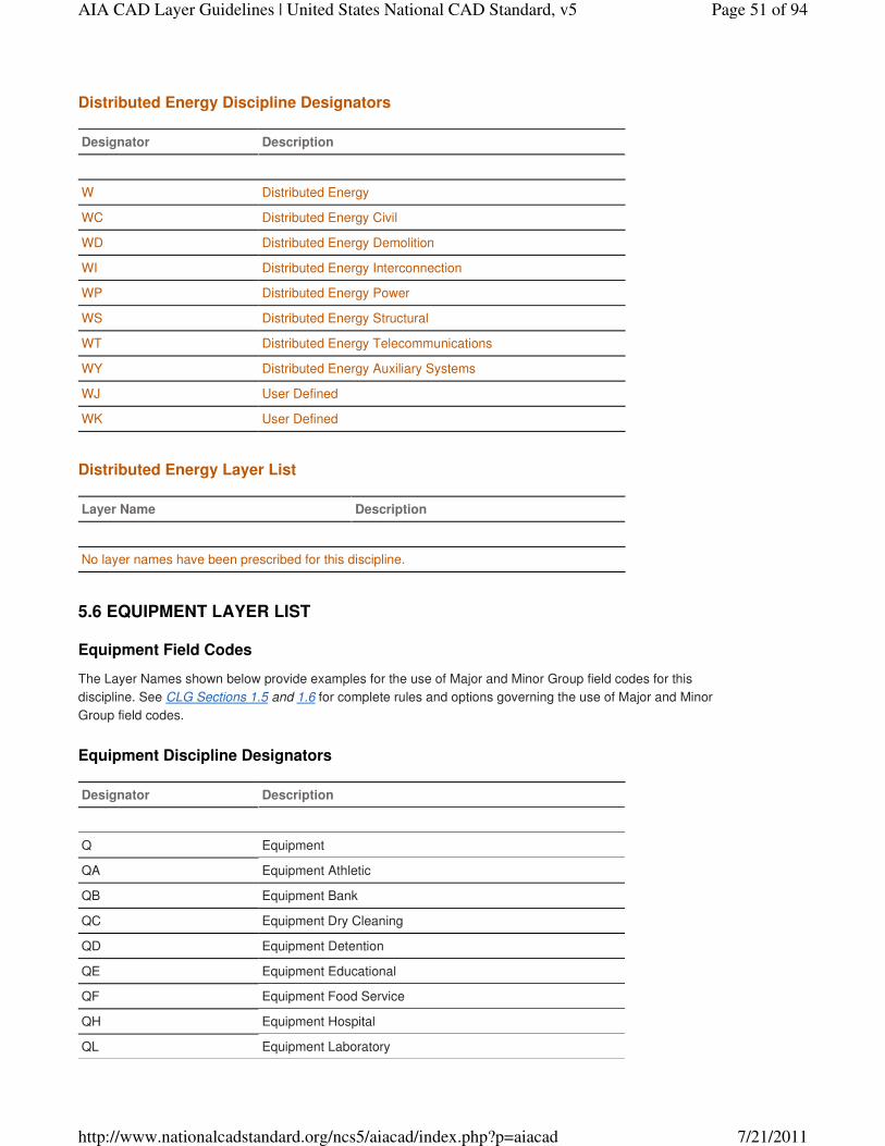
Distributed Energy Discipline Designators
Designator Description
W Distributed Energy
WC Distributed Energy Civil
WD Distributed Energy Demolition
WI Distributed Energy Interconnection
WP Distributed Energy Power
WS Distributed Energy Structural
WT Distributed Energy Telecommunications
WY Distributed Energy Auxiliary Systems
WJ User Defined
WK User Defined
Distributed Energy Layer List
Layer Name Description
No layer names have been prescribed for this discipline.
Equipment Field Codes
The Layer Names shown below provide examples for the use of Major and Minor Group field codes for this
discipline. See CLG Sections 1.5 and 1.6 for complete rules and options governing the use of Major and Minor
Group field codes.
Equipment Discipline Designators
Designator Description
Q Equipment
QA Equipment Athletic
QB Equipment Bank
QC Equipment Dry Cleaning
QD Equipment Detention
QE Equipment Educational
QF Equipment Food Service
QH Equipment Hospital
QL Equipment Laboratory
5.6 EQUIPMENT LAYER LIST
Page 51 of 94AIA CAD Layer Guidelines | United States National CAD Standard, v5
7/21/2011http://www.nationalcadstandard.org/ncs5/aiacad/index.php?p=aiacad
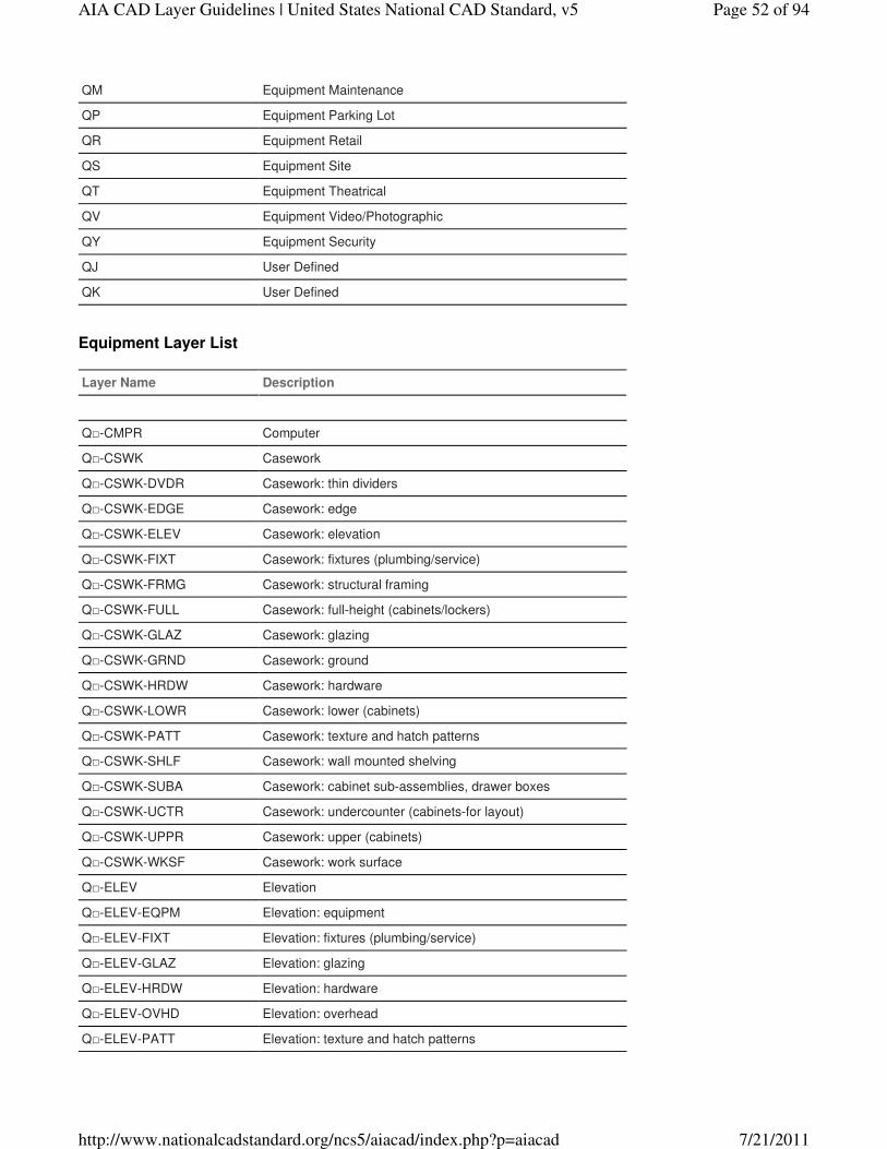
QM Equipment Maintenance
QP Equipment Parking Lot
QR Equipment Retail
QS Equipment Site
QT Equipment Theatrical
QV Equipment Video/Photographic
QY Equipment Security
QJ User Defined
QK User Defined
Equipment Layer List
Layer Name Description
Q□-CMPR Computer
Q□-CSWK Casework
Q□-CSWK-DVDR Casework: thin dividers
Q□-CSWK-EDGE Casework: edge
Q□-CSWK-ELEV Casework: elevation
Q□-CSWK-FIXT Casework: fixtures (plumbing/service)
Q□-CSWK-FRMG Casework: structural framing
Q□-CSWK-FULL Casework: full-height (cabinets/lockers)
Q□-CSWK-GLAZ Casework: glazing
Q□-CSWK-GRND Casework: ground
Q□-CSWK-HRDW Casework: hardware
Q□-CSWK-LOWR Casework: lower (cabinets)
Q□-CSWK-PATT Casework: texture and hatch patterns
Q□-CSWK-SHLF Casework: wall mounted shelving
Q□-CSWK-SUBA Casework: cabinet sub-assemblies, drawer boxes
Q□-CSWK-UCTR Casework: undercounter (cabinets-for layout)
Q□-CSWK-UPPR Casework: upper (cabinets)
Q□-CSWK-WKSF Casework: work surface
Q□-ELEV Elevation
Q□-ELEV-EQPM Elevation: equipment
Q□-ELEV-FIXT Elevation: fixtures (plumbing/service)
Q□-ELEV-GLAZ Elevation: glazing
Q□-ELEV-HRDW Elevation: hardware
Q□-ELEV-OVHD Elevation: overhead
Q□-ELEV-PATT Elevation: texture and hatch patterns
Page 52 of 94AIA CAD Layer Guidelines | United States National CAD Standard, v5
7/21/2011http://www.nationalcadstandard.org/ncs5/aiacad/index.php?p=aiacad
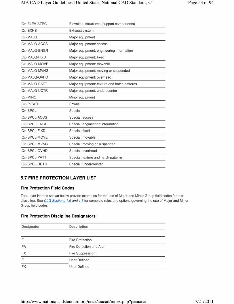
Q□-ELEV-STRC Elevation: structures (support components)
Q□-EXHS Exhaust system
Q□-MAJQ Major equipment
Q□-MAJQ-ACCS Major equipment: access
Q□-MAJQ-ENGR Major equipment: engineering information
Q□-MAJQ-FIXD Major equipment: fixed
Q□-MAJQ-MOVE Major equipment: movable
Q□-MAJQ-MVNG Major equipment: moving or suspended
Q□-MAJQ-OVHD Major equipment: overhead
Q□-MAJQ-PATT Major equipment: texture and hatch patterns
Q□-MAJQ-UCTR Major equipment: undercounter
Q□-MINQ Minor equipment
Q□-POWR Power
Q□-SPCL Special
Q□-SPCL-ACCS Special: access
Q□-SPCL-ENGR Special: engineering information
Q□-SPCL-FIXD Special: fixed
Q□-SPCL-MOVE Special: movable
Q□-SPCL-MVNG Special: moving or suspended
Q□-SPCL-OVHD Special: overhead
Q□-SPCL-PATT Special: texture and hatch patterns
Q□-SPCL-UCTR Special: undercounter
Fire Protection Field Codes
The Layer Names shown below provide examples for the use of Major and Minor Group field codes for this
discipline. See CLG Sections 1.5 and 1.6 for complete rules and options governing the use of Major and Minor
Group field codes.
Fire Protection Discipline Designators
Designator Description
F Fire Protection
FA Fire Detection and Alarm
FX Fire Suppression
FJ User Defined
FK User Defined
5.7 FIRE PROTECTION LAYER LIST
Page 53 of 94AIA CAD Layer Guidelines | United States National CAD Standard, v5
7/21/2011http://www.nationalcadstandard.org/ncs5/aiacad/index.php?p=aiacad

Fire Protection Layer List
Layer Name Description
F□-AFFF Aqueous film-forming foam system
F□-AFFF-EQPM Aqueous film-forming foam system: equipment
F□-AFFF-PIPE Aqueous film-forming foam system: piping
F□-CO2S CO2 system
F□-CO2S-EQPM CO2 system: equipment
F□-CO2S-PIPE CO2 system: piping
F□-HALN Halon
F□-HALN-EQPM Halon: equipment
F□-HALN-PIPE Halon: piping
F□-IGAS Inert gas
F□-IGAS-EQPM Inert gas: equipment
F□-IGAS-PIPE Inert gas: piping
F□-PROT Fire protection system
F□-PROT-ALRM Fire protection system: alarm
F□-PROT-EQPM Fire protection system: equipment
F□-PROT-EXTI Fire protection system: extinguishers
F□-PROT-HOSE Fire protection system: hoses
F□-PROT-HYDT Fire protection: hydrants and connections
F□-PROT-RATE Fire protection system: ratings
F□-PROT-RATE-DOOR Fire protection system: ratings: doors
F□-PROT-RATE-WALL Fire protection system: ratings: wall
F□-PROT-SMOK Fire protection system: smoke detector/heat sensors
F□-SPKL Sprinkler
F□-SPKL-C LHD Sprinkler: ceiling heads
F□-SPKL-E QPM Sprinkler: equipment
F□-SPKL-O THD Sprinkler: other heads
F□-SPKL-PI PE Sprinkler: piping
General Field Codes
The Layer Names shown below provide examples for the use of Major and Minor Group field codes for this
discipline. See CLG Sections 1.5 and 1.6 for complete rules and options governing the use of Major and Minor
Group field codes.
5.8 GENERAL LAYER LIST
Page 54 of 94AIA CAD Layer Guidelines | United States National CAD Standard, v5
7/21/2011http://www.nationalcadstandard.org/ncs5/aiacad/index.php?p=aiacad
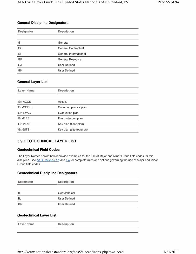
General Discipline Designators
Designator Description
G General
GC General Contractual
GI General Informational
GR General Resource
GJ User Defined
GK User Defined
General Layer List
Layer Name Description
G□-ACCS Access
G□-CODE Code compliance plan
G□-EVAC Evacuation plan
G□-FIRE Fire protection plan
G□-PLAN Key plan (floor plan)
G□-SITE Key plan (site features)
Geotechnical Field Codes
The Layer Names shown below provide examples for the use of Major and Minor Group field codes for this
discipline. See CLG Sections 1.5 and 1.6 for complete rules and options governing the use of Major and Minor
Group field codes.
Geotechnical Discipline Designators
Designator Description
B Geotechnical
BJ User Defined
BK User Defined
Geotechnical Layer List
Layer Name Description
5.9 GEOTECHNICAL LAYER LIST
Page 55 of 94AIA CAD Layer Guidelines | United States National CAD Standard, v5
7/21/2011http://www.nationalcadstandard.org/ncs5/aiacad/index.php?p=aiacad
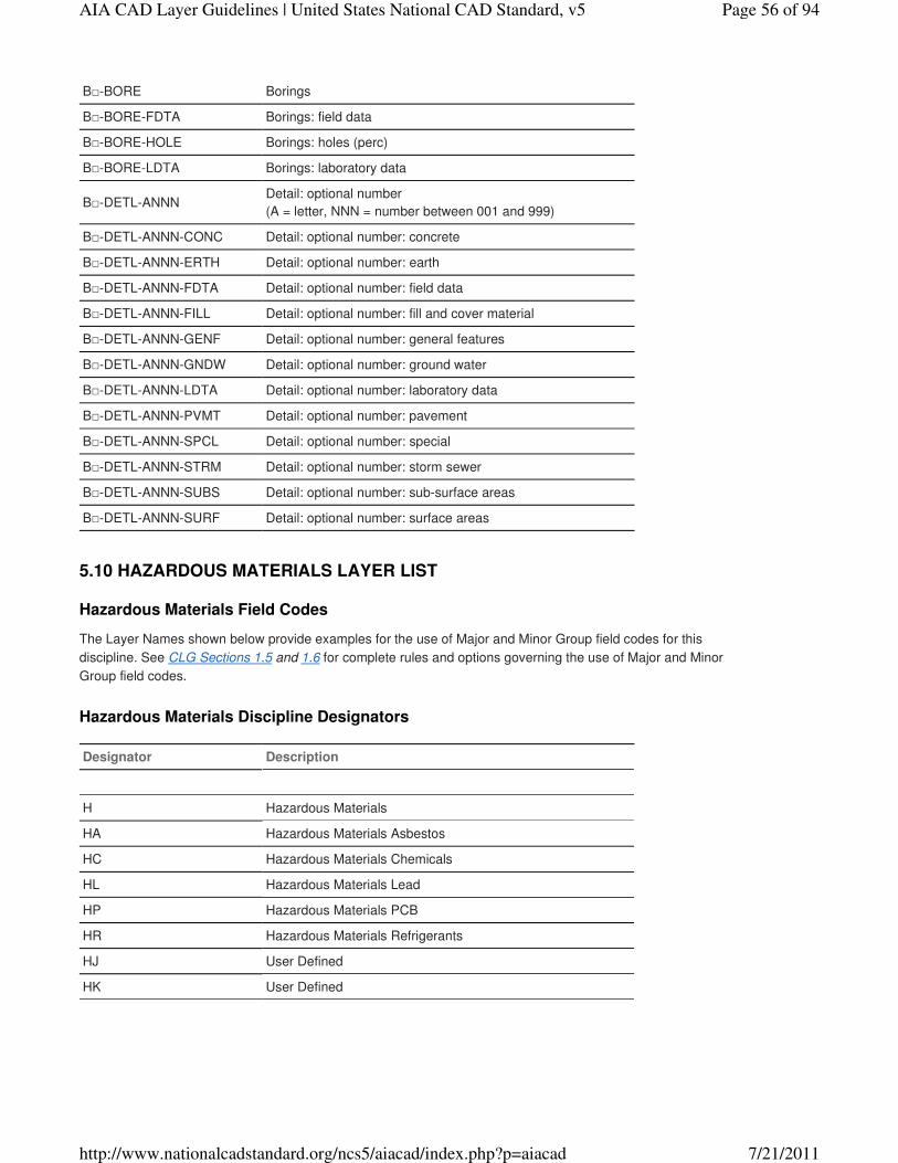
B□-BORE Borings
B□-BORE-FDTA Borings: field data
B□-BORE-HOLE Borings: holes (perc)
B□-BORE-LDTA Borings: laboratory data
B□-DETL-ANNNDetail: optional number
(A = letter, NNN = number between 001 and 999)
B□-DETL-ANNN-CONC Detail: optional number: concrete
B□-DETL-ANNN-ERTH Detail: optional number: earth
B□-DETL-ANNN-FDTA Detail: optional number: field data
B□-DETL-ANNN-FILL Detail: optional number: fill and cover material
B□-DETL-ANNN-GENF Detail: optional number: general features
B□-DETL-ANNN-GNDW Detail: optional number: ground water
B□-DETL-ANNN-LDTA Detail: optional number: laboratory data
B□-DETL-ANNN-PVMT Detail: optional number: pavement
B□-DETL-ANNN-SPCL Detail: optional number: special
B□-DETL-ANNN-STRM Detail: optional number: storm sewer
B□-DETL-ANNN-SUBS Detail: optional number: sub-surface areas
B□-DETL-ANNN-SURF Detail: optional number: surface areas
Hazardous Materials Field Codes
The Layer Names shown below provide examples for the use of Major and Minor Group field codes for this
discipline. See CLG Sections 1.5 and 1.6 for complete rules and options governing the use of Major and Minor
Group field codes.
Hazardous Materials Discipline Designators
Designator Description
H Hazardous Materials
HA Hazardous Materials Asbestos
HC Hazardous Materials Chemicals
HL Hazardous Materials Lead
HP Hazardous Materials PCB
HR Hazardous Materials Refrigerants
HJ User Defined
HK User Defined
5.10 HAZARDOUS MATERIALS LAYER LIST
Page 56 of 94AIA CAD Layer Guidelines | United States National CAD Standard, v5
7/21/2011http://www.nationalcadstandard.org/ncs5/aiacad/index.php?p=aiacad
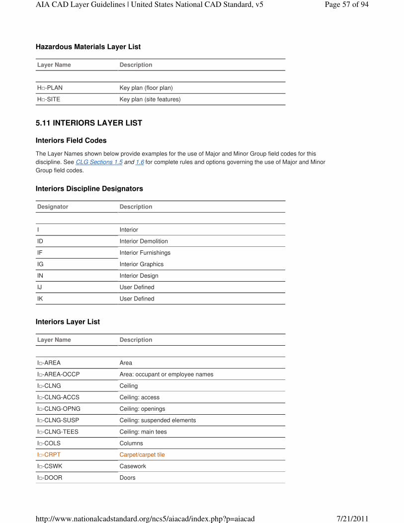
Hazardous Materials Layer List
Layer Name Description
H□-PLAN Key plan (floor plan)
H□-SITE Key plan (site features)
Interiors Field Codes
The Layer Names shown below provide examples for the use of Major and Minor Group field codes for this
discipline. See CLG Sections 1.5 and 1.6 for complete rules and options governing the use of Major and Minor
Group field codes.
Interiors Discipline Designators
Designator Description
I Interior
ID Interior Demolition
IF Interior Furnishings
IG Interior Graphics
IN Interior Design
IJ User Defined
IK User Defined
Interiors Layer List
Layer Name Description
I□-AREA Area
I□-AREA-OCCP Area: occupant or employee names
I□-CLNG Ceiling
I□-CLNG-ACCS Ceiling: access
I□-CLNG-OPNG Ceiling: openings
I□-CLNG-SUSP Ceiling: suspended elements
I□-CLNG-TEES Ceiling: main tees
I□-COLS Columns
I□-CRPT Carpet/carpet tile
I□-CSWK Casework
I□-DOOR Doors
5.11 INTERIORS LAYER LIST
Page 57 of 94AIA CAD Layer Guidelines | United States National CAD Standard, v5
7/21/2011http://www.nationalcadstandard.org/ncs5/aiacad/index.php?p=aiacad
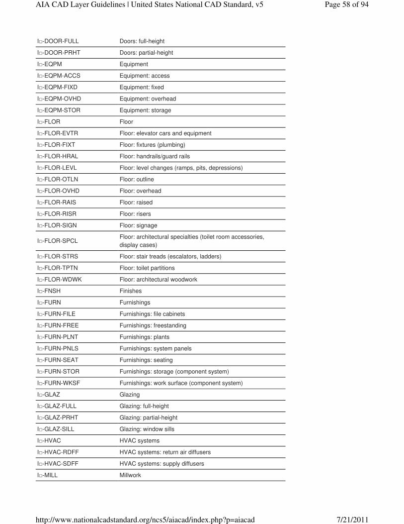
I□-DOOR-FULL Doors: full-height
I□-DOOR-PRHT Doors: partial-height
I□-EQPM Equipment
I□-EQPM-ACCS Equipment: access
I□-EQPM-FIXD Equipment: fixed
I□-EQPM-OVHD Equipment: overhead
I□-EQPM-STOR Equipment: storage
I□-FLOR Floor
I□-FLOR-EVTR Floor: elevator cars and equipment
I□-FLOR-FIXT Floor: fixtures (plumbing)
I□-FLOR-HRAL Floor: handrails/guard rails
I□-FLOR-LEVL Floor: level changes (ramps, pits, depressions)
I□-FLOR-OTLN Floor: outline
I□-FLOR-OVHD Floor: overhead
I□-FLOR-RAIS Floor: raised
I□-FLOR-RISR Floor: risers
I□-FLOR-SIGN Floor: signage
I□-FLOR-SPCLFloor: architectural specialties (toilet room accessories,
display cases)
I□-FLOR-STRS Floor: stair treads (escalators, ladders)
I□-FLOR-TPTN Floor: toilet partitions
I□-FLOR-WDWK Floor: architectural woodwork
I□-FNSH Finishes
I□-FURN Furnishings
I□-FURN-FILE Furnishings: file cabinets
I□-FURN-FREE Furnishings: freestanding
I□-FURN-PLNT Furnishings: plants
I□-FURN-PNLS Furnishings: system panels
I□-FURN-SEAT Furnishings: seating
I□-FURN-STOR Furnishings: storage (component system)
I□-FURN-WKSF Furnishings: work surface (component system)
I□-GLAZ Glazing
I□-GLAZ-FULL Glazing: full-height
I□-GLAZ-PRHT Glazing: partial-height
I□-GLAZ-SILL Glazing: window sills
I□-HVAC HVAC systems
I□-HVAC-RDFF HVAC systems: return air diffusers
I□-HVAC-SDFF HVAC systems: supply diffusers
I□-MILL Millwork
Page 58 of 94AIA CAD Layer Guidelines | United States National CAD Standard, v5
7/21/2011http://www.nationalcadstandard.org/ncs5/aiacad/index.php?p=aiacad
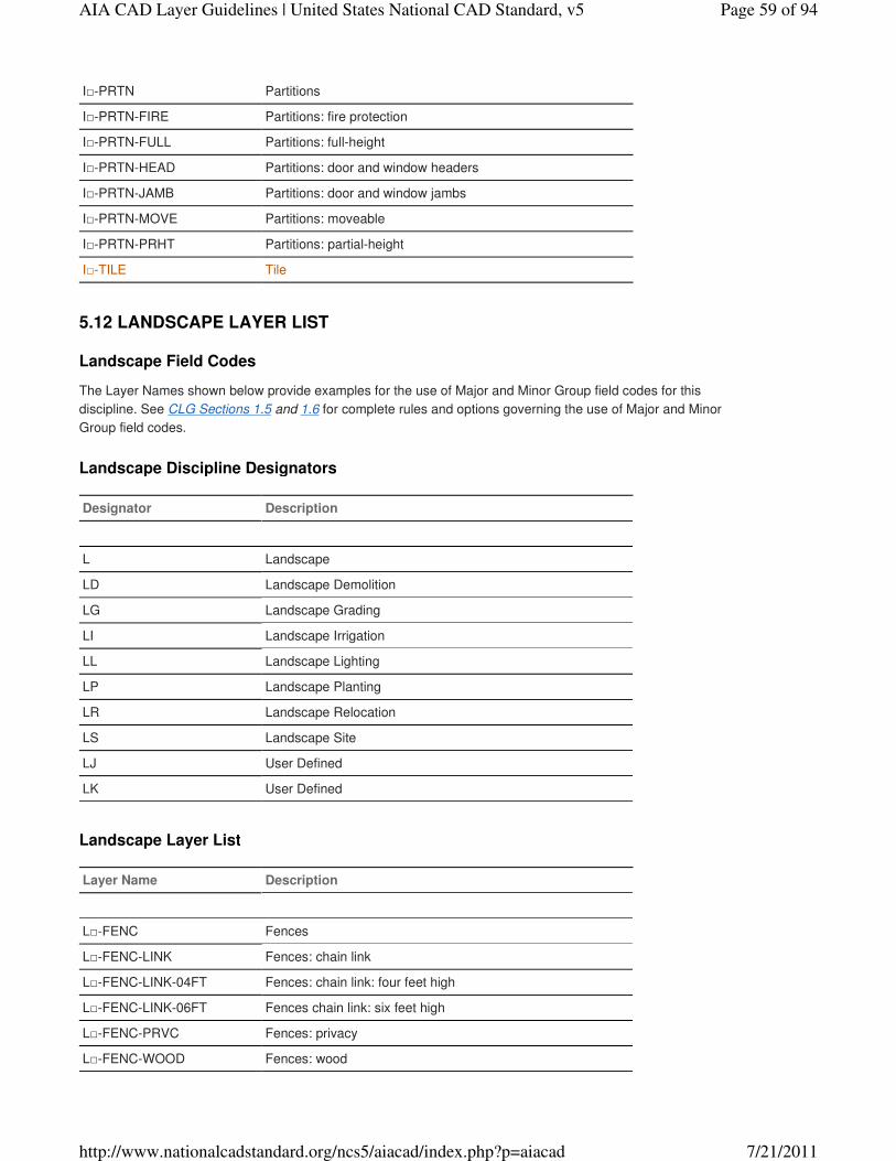
I□-PRTN Partitions
I□-PRTN-FIRE Partitions: fire protection
I□-PRTN-FULL Partitions: full-height
I□-PRTN-HEAD Partitions: door and window headers
I□-PRTN-JAMB Partitions: door and window jambs
I□-PRTN-MOVE Partitions: moveable
I□-PRTN-PRHT Partitions: partial-height
I□-TILE Tile
Landscape Field Codes
The Layer Names shown below provide examples for the use of Major and Minor Group field codes for this
discipline. See CLG Sections 1.5 and 1.6 for complete rules and options governing the use of Major and Minor
Group field codes.
Landscape Discipline Designators
Designator Description
L Landscape
LD Landscape Demolition
LG Landscape Grading
LI Landscape Irrigation
LL Landscape Lighting
LP Landscape Planting
LR Landscape Relocation
LS Landscape Site
LJ User Defined
LK User Defined
Landscape Layer List
Layer Name Description
L□-FENC Fences
L□-FENC-LINK Fences: chain link
L□-FENC-LINK-04FT Fences: chain link: four feet high
L□-FENC-LINK-06FT Fences chain link: six feet high
L□-FENC-PRVC Fences: privacy
L□-FENC-WOOD Fences: wood
5.12 LANDSCAPE LAYER LIST
Page 59 of 94AIA CAD Layer Guidelines | United States National CAD Standard, v5
7/21/2011http://www.nationalcadstandard.org/ncs5/aiacad/index.php?p=aiacad
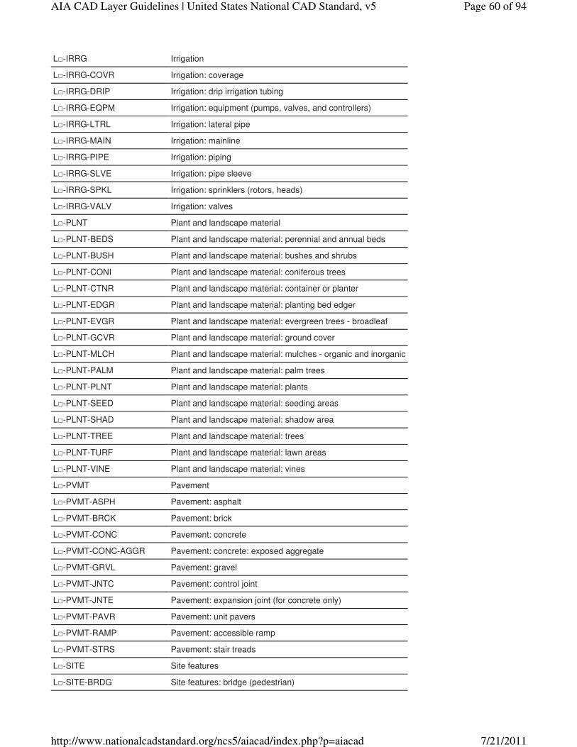
L□-IRRG Irrigation
L□-IRRG-COVR Irrigation: coverage
L□-IRRG-DRIP Irrigation: drip irrigation tubing
L□-IRRG-EQPM Irrigation: equipment (pumps, valves, and controllers)
L□-IRRG-LTRL Irrigation: lateral pipe
L□-IRRG-MAIN Irrigation: mainline
L□-IRRG-PIPE Irrigation: piping
L□-IRRG-SLVE Irrigation: pipe sleeve
L□-IRRG-SPKL Irrigation: sprinklers (rotors, heads)
L□-IRRG-VALV Irrigation: valves
L□-PLNT Plant and landscape material
L□-PLNT-BEDS Plant and landscape material: perennial and annual beds
L□-PLNT-BUSH Plant and landscape material: bushes and shrubs
L□-PLNT-CONI Plant and landscape material: coniferous trees
L□-PLNT-CTNR Plant and landscape material: container or planter
L□-PLNT-EDGR Plant and landscape material: planting bed edger
L□-PLNT-EVGR Plant and landscape material: evergreen trees - broadleaf
L□-PLNT-GCVR Plant and landscape material: ground cover
L□-PLNT-MLCH Plant and landscape material: mulches - organic and inorganic
L□-PLNT-PALM Plant and landscape material: palm trees
L□-PLNT-PLNT Plant and landscape material: plants
L□-PLNT-SEED Plant and landscape material: seeding areas
L□-PLNT-SHAD Plant and landscape material: shadow area
L□-PLNT-TREE Plant and landscape material: trees
L□-PLNT-TURF Plant and landscape material: lawn areas
L□-PLNT-VINE Plant and landscape material: vines
L□-PVMT Pavement
L□-PVMT-ASPH Pavement: asphalt
L□-PVMT-BRCK Pavement: brick
L□-PVMT-CONC Pavement: concrete
L□-PVMT-CONC-AGGR Pavement: concrete: exposed aggregate
L□-PVMT-GRVL Pavement: gravel
L□-PVMT-JNTC Pavement: control joint
L□-PVMT-JNTE Pavement: expansion joint (for concrete only)
L□-PVMT-PAVR Pavement: unit pavers
L□-PVMT-RAMP Pavement: accessible ramp
L□-PVMT-STRS Pavement: stair treads
L□-SITE Site features
L□-SITE-BRDG Site features: bridge (pedestrian)
Page 60 of 94AIA CAD Layer Guidelines | United States National CAD Standard, v5
7/21/2011http://www.nationalcadstandard.org/ncs5/aiacad/index.php?p=aiacad
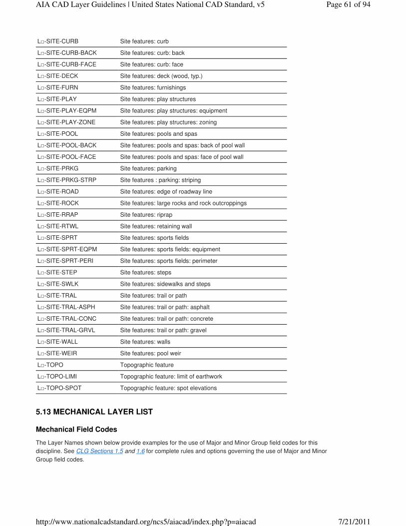
L□-SITE-CURB Site features: curb
L□-SITE-CURB-BACK Site features: curb: back
L□-SITE-CURB-FACE Site features: curb: face
L□-SITE-DECK Site features: deck (wood, typ.)
L□-SITE-FURN Site features: furnishings
L□-SITE-PLAY Site features: play structures
L□-SITE-PLAY-EQPM Site features: play structures: equipment
L□-SITE-PLAY-ZONE Site features: play structures: zoning
L□-SITE-POOL Site features: pools and spas
L□-SITE-POOL-BACK Site features: pools and spas: back of pool wall
L□-SITE-POOL-FACE Site features: pools and spas: face of pool wall
L□-SITE-PRKG Site features: parking
L□-SITE-PRKG-STRP Site features : parking: striping
L□-SITE-ROAD Site features: edge of roadway line
L□-SITE-ROCK Site features: large rocks and rock outcroppings
L□-SITE-RRAP Site features: riprap
L□-SITE-RTWL Site features: retaining wall
L□-SITE-SPRT Site features: sports fields
L□-SITE-SPRT-EQPM Site features: sports fields: equipment
L□-SITE-SPRT-PERI Site features: sports fields: perimeter
L□-SITE-STEP Site features: steps
L□-SITE-SWLK Site features: sidewalks and steps
L□-SITE-TRAL Site features: trail or path
L□-SITE-TRAL-ASPH Site features: trail or path: asphalt
L□-SITE-TRAL-CONC Site features: trail or path: concrete
L□-SITE-TRAL-GRVL Site features: trail or path: gravel
L□-SITE-WALL Site features: walls
L□-SITE-WEIR Site features: pool weir
L□-TOPO Topographic feature
L□-TOPO-LIMI Topographic feature: limit of earthwork
L□-TOPO-SPOT Topographic feature: spot elevations
Mechanical Field Codes
The Layer Names shown below provide examples for the use of Major and Minor Group field codes for this
discipline. See CLG Sections 1.5 and 1.6 for complete rules and options governing the use of Major and Minor
Group field codes.
5.13 MECHANICAL LAYER LIST
Page 61 of 94AIA CAD Layer Guidelines | United States National CAD Standard, v5
7/21/2011http://www.nationalcadstandard.org/ncs5/aiacad/index.php?p=aiacad
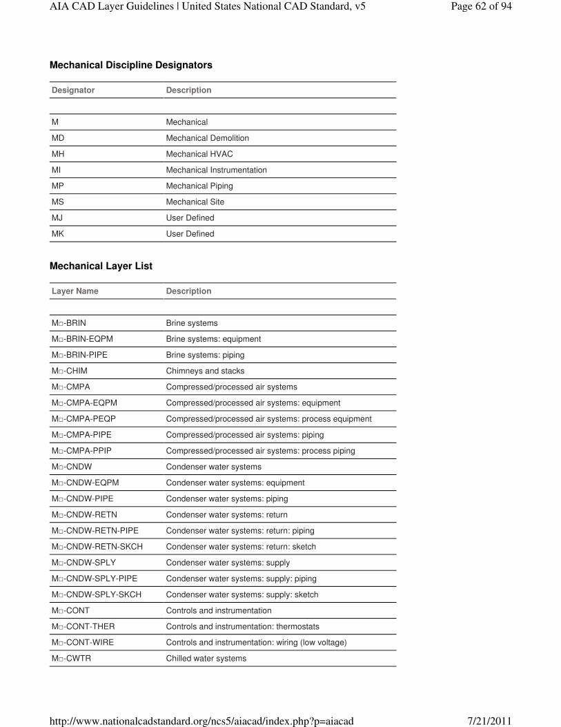
Mechanical Discipline Designators
Designator Description
M Mechanical
MD Mechanical Demolition
MH Mechanical HVAC
MI Mechanical Instrumentation
MP Mechanical Piping
MS Mechanical Site
MJ User Defined
MK User Defined
Mechanical Layer List
Layer Name Description
M□-BRIN Brine systems
M□-BRIN-EQPM Brine systems: equipment
M□-BRIN-PIPE Brine systems: piping
M□-CHIM Chimneys and stacks
M□-CMPA Compressed/processed air systems
M□-CMPA-EQPM Compressed/processed air systems: equipment
M□-CMPA-PEQP Compressed/processed air systems: process equipment
M□-CMPA-PIPE Compressed/processed air systems: piping
M□-CMPA-PPIP Compressed/processed air systems: process piping
M□-CNDW Condenser water systems
M□-CNDW-EQPM Condenser water systems: equipment
M□-CNDW-PIPE Condenser water systems: piping
M□-CNDW-RETN Condenser water systems: return
M□-CNDW-RETN-PIPE Condenser water systems: return: piping
M□-CNDW-RETN-SKCH Condenser water systems: return: sketch
M□-CNDW-SPLY Condenser water systems: supply
M□-CNDW-SPLY-PIPE Condenser water systems: supply: piping
M□-CNDW-SPLY-SKCH Condenser water systems: supply: sketch
M□-CONT Controls and instrumentation
M□-CONT-THER Controls and instrumentation: thermostats
M□-CONT-WIRE Controls and instrumentation: wiring (low voltage)
M□-CWTR Chilled water systems
Page 62 of 94AIA CAD Layer Guidelines | United States National CAD Standard, v5
7/21/2011http://www.nationalcadstandard.org/ncs5/aiacad/index.php?p=aiacad
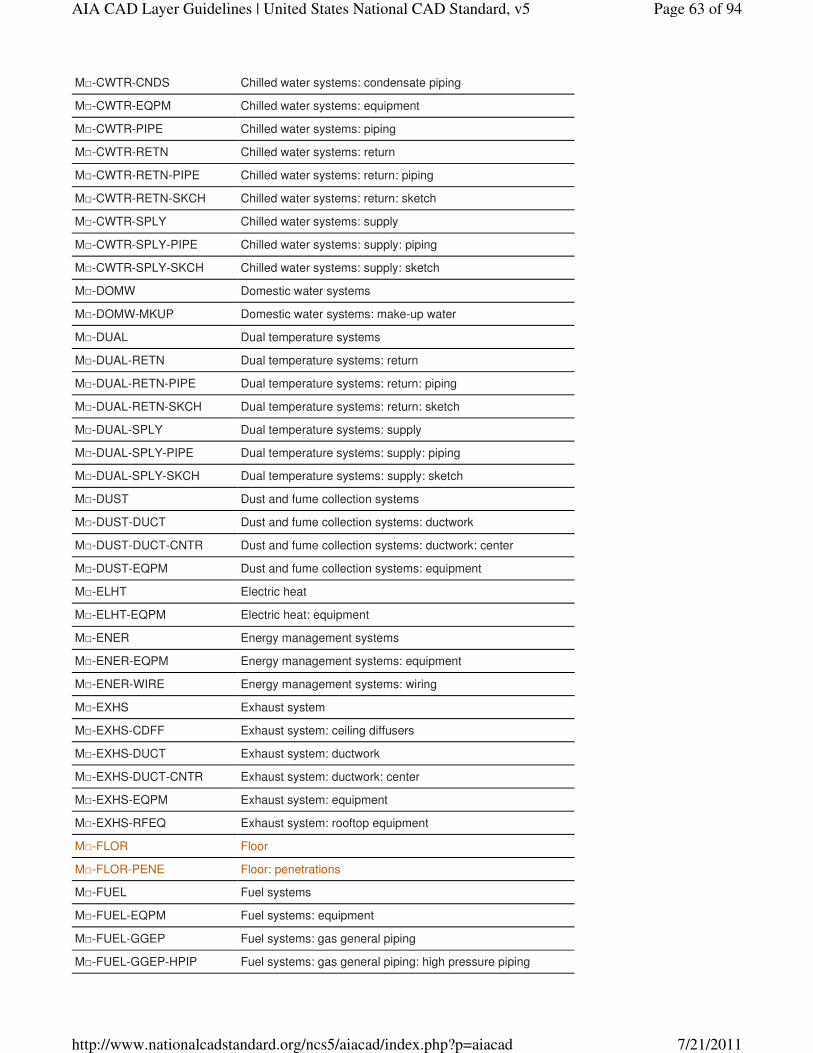
M□-CWTR-CNDS Chilled water systems: condensate piping
M□-CWTR-EQPM Chilled water systems: equipment
M□-CWTR-PIPE Chilled water systems: piping
M□-CWTR-RETN Chilled water systems: return
M□-CWTR-RETN-PIPE Chilled water systems: return: piping
M□-CWTR-RETN-SKCH Chilled water systems: return: sketch
M□-CWTR-SPLY Chilled water systems: supply
M□-CWTR-SPLY-PIPE Chilled water systems: supply: piping
M□-CWTR-SPLY-SKCH Chilled water systems: supply: sketch
M□-DOMW Domestic water systems
M□-DOMW-MKUP Domestic water systems: make-up water
M□-DUAL Dual temperature systems
M□-DUAL-RETN Dual temperature systems: return
M□-DUAL-RETN-PIPE Dual temperature systems: return: piping
M□-DUAL-RETN-SKCH Dual temperature systems: return: sketch
M□-DUAL-SPLY Dual temperature systems: supply
M□-DUAL-SPLY-PIPE Dual temperature systems: supply: piping
M□-DUAL-SPLY-SKCH Dual temperature systems: supply: sketch
M□-DUST Dust and fume collection systems
M□-DUST-DUCT Dust and fume collection systems: ductwork
M□-DUST-DUCT-CNTR Dust and fume collection systems: ductwork: center
M□-DUST-EQPM Dust and fume collection systems: equipment
M□-ELHT Electric heat
M□-ELHT-EQPM Electric heat: equipment
M□-ENER Energy management systems
M□-ENER-EQPM Energy management systems: equipment
M□-ENER-WIRE Energy management systems: wiring
M□-EXHS Exhaust system
M□-EXHS-CDFF Exhaust system: ceiling diffusers
M□-EXHS-DUCT Exhaust system: ductwork
M□-EXHS-DUCT-CNTR Exhaust system: ductwork: center
M□-EXHS-EQPM Exhaust system: equipment
M□-EXHS-RFEQ Exhaust system: rooftop equipment
M□-FLOR Floor
M□-FLOR-PENE Floor: penetrations
M□-FUEL Fuel systems
M□-FUEL-EQPM Fuel systems: equipment
M□-FUEL-GGEP Fuel systems: gas general piping
M□-FUEL-GGEP-HPIP Fuel systems: gas general piping: high pressure piping
Page 63 of 94AIA CAD Layer Guidelines | United States National CAD Standard, v5
7/21/2011http://www.nationalcadstandard.org/ncs5/aiacad/index.php?p=aiacad
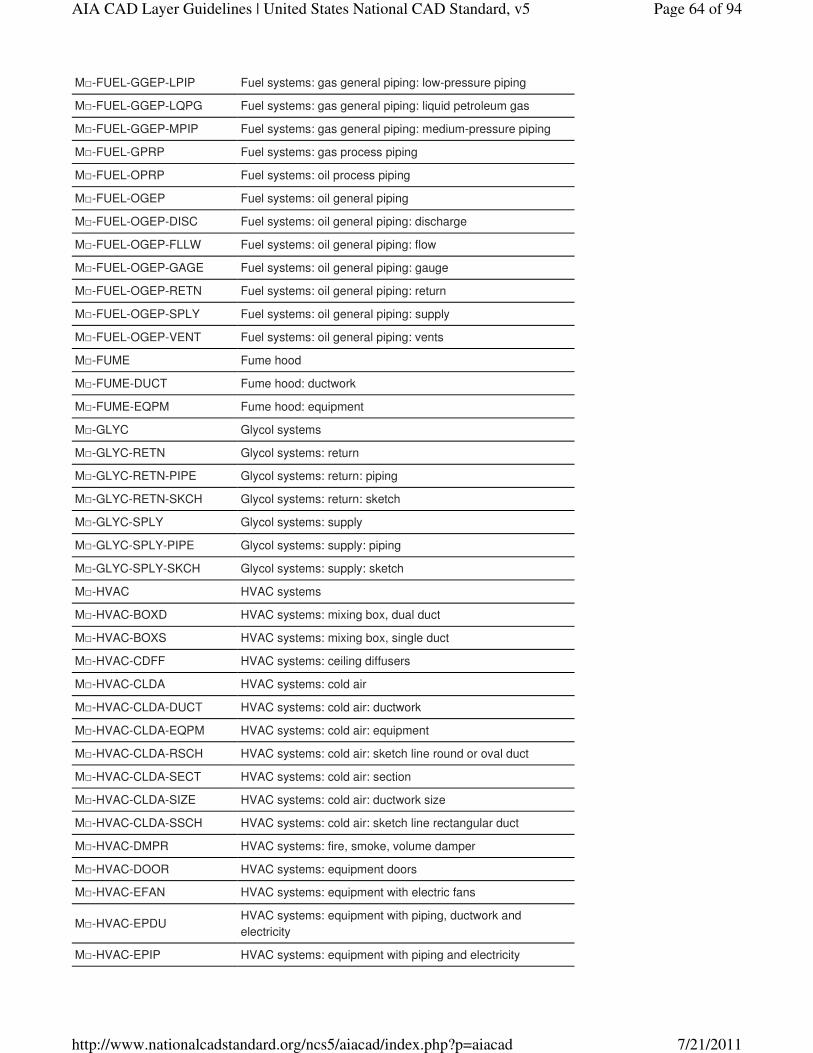
M□-FUEL-GGEP-LPIP Fuel systems: gas general piping: low-pressure piping
M□-FUEL-GGEP-LQPG Fuel systems: gas general piping: liquid petroleum gas
M□-FUEL-GGEP-MPIP Fuel systems: gas general piping: medium-pressure piping
M□-FUEL-GPRP Fuel systems: gas process piping
M□-FUEL-OPRP Fuel systems: oil process piping
M□-FUEL-OGEP Fuel systems: oil general piping
M□-FUEL-OGEP-DISC Fuel systems: oil general piping: discharge
M□-FUEL-OGEP-FLLW Fuel systems: oil general piping: flow
M□-FUEL-OGEP-GAGE Fuel systems: oil general piping: gauge
M□-FUEL-OGEP-RETN Fuel systems: oil general piping: return
M□-FUEL-OGEP-SPLY Fuel systems: oil general piping: supply
M□-FUEL-OGEP-VENT Fuel systems: oil general piping: vents
M□-FUME Fume hood
M□-FUME-DUCT Fume hood: ductwork
M□-FUME-EQPM Fume hood: equipment
M□-GLYC Glycol systems
M□-GLYC-RETN Glycol systems: return
M□-GLYC-RETN-PIPE Glycol systems: return: piping
M□-GLYC-RETN-SKCH Glycol systems: return: sketch
M□-GLYC-SPLY Glycol systems: supply
M□-GLYC-SPLY-PIPE Glycol systems: supply: piping
M□-GLYC-SPLY-SKCH Glycol systems: supply: sketch
M□-HVAC HVAC systems
M□-HVAC-BOXD HVAC systems: mixing box, dual duct
M□-HVAC-BOXS HVAC systems: mixing box, single duct
M□-HVAC-CDFF HVAC systems: ceiling diffusers
M□-HVAC-CLDA HVAC systems: cold air
M□-HVAC-CLDA-DUCT HVAC systems: cold air: ductwork
M□-HVAC-CLDA-EQPM HVAC systems: cold air: equipment
M□-HVAC-CLDA-RSCH HVAC systems: cold air: sketch line round or oval duct
M□-HVAC-CLDA-SECT HVAC systems: cold air: section
M□-HVAC-CLDA-SIZE HVAC systems: cold air: ductwork size
M□-HVAC-CLDA-SSCH HVAC systems: cold air: sketch line rectangular duct
M□-HVAC-DMPR HVAC systems: fire, smoke, volume damper
M□-HVAC-DOOR HVAC systems: equipment doors
M□-HVAC-EFAN HVAC systems: equipment with electric fans
M□-HVAC-EPDUHVAC systems: equipment with piping, ductwork and
electricity
M□-HVAC-EPIP HVAC systems: equipment with piping and electricity
Page 64 of 94AIA CAD Layer Guidelines | United States National CAD Standard, v5
7/21/2011http://www.nationalcadstandard.org/ncs5/aiacad/index.php?p=aiacad
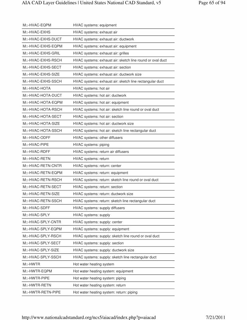
M□-HVAC-EQPM HVAC systems: equipment
M□-HVAC-EXHS HVAC systems: exhaust air
M□-HVAC-EXHS-DUCT HVAC systems: exhaust air: ductwork
M□-HVAC-EXHS-EQPM HVAC systems: exhaust air: equipment
M□-HVAC-EXHS-GRIL HVAC systems: exhaust air: grilles
M□-HVAC-EXHS-RSCH HVAC systems: exhaust air: sketch line round or oval duct
M□-HVAC-EXHS-SECT HVAC systems: exhaust air: section
M□-HVAC-EXHS-SIZE HVAC systems: exhaust air: ductwork size
M□-HVAC-EXHS-SSCH HVAC systems: exhaust air: sketch line rectangular duct
M□-HVAC-HOTA HVAC systems: hot air
M□-HVAC-HOTA-DUCT HVAC systems: hot air: ductwork
M□-HVAC-HOTA-EQPM HVAC systems: hot air: equipment
M□-HVAC-HOTA-RSCH HVAC systems: hot air: sketch line round or oval duct
M□-HVAC-HOTA-SECT HVAC systems: hot air: section
M□-HVAC-HOTA-SIZE HVAC systems: hot air: ductwork size
M□-HVAC-HOTA-SSCH HVAC systems: hot air: sketch line rectangular duct
M□-HVAC-ODFF HVAC systems: other diffusers
M□-HVAC-PIPE HVAC systems: piping
M□-HVAC-RDFF HVAC systems: return air diffusers
M□-HVAC-RETN HVAC systems: return
M□-HVAC-RETN-CNTR HVAC systems: return: center
M□-HVAC-RETN-EQPM HVAC systems: return: equipment
M□-HVAC-RETN-RSCH HVAC systems: return: sketch line round or oval duct
M□-HVAC-RETN-SECT HVAC systems: return: section
M□-HVAC-RETN-SIZE HVAC systems: return: ductwork size
M□-HVAC-RETN-SSCH HVAC systems: return: sketch line rectangular duct
M□-HVAC-SDFF HVAC systems: supply diffusers
M□-HVAC-SPLY HVAC systems: supply
M□-HVAC-SPLY-CNTR HVAC systems: supply: center
M□-HVAC-SPLY-EQPM HVAC systems: supply: equipment
M□-HVAC-SPLY-RSCH HVAC systems: supply: sketch line round or oval duct
M□-HVAC-SPLY-SECT HVAC systems: supply: section
M□-HVAC-SPLY-SIZE HVAC systems: supply: ductwork size
M□-HVAC-SPLY-SSCH HVAC systems: supply: sketch line rectangular duct
M□-HWTR Hot water heating system
M□-HWTR-EQPM Hot water heating system: equipment
M□-HWTR-PIPE Hot water heating system: piping
M□-HWTR-RETN Hot water heating system: return
M□-HWTR-RETN-PIPE Hot water heating system: return: piping
Page 65 of 94AIA CAD Layer Guidelines | United States National CAD Standard, v5
7/21/2011http://www.nationalcadstandard.org/ncs5/aiacad/index.php?p=aiacad
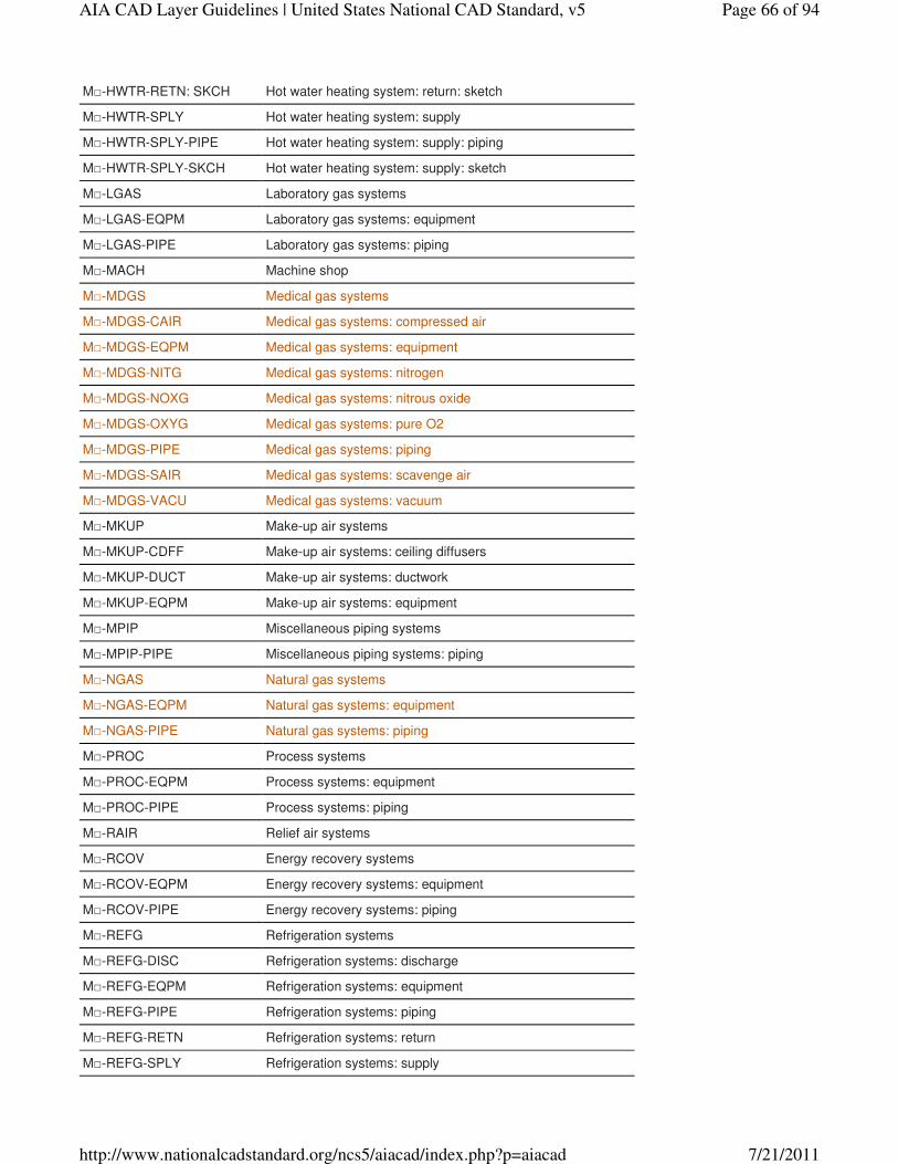
M□-HWTR-RETN: SKCH Hot water heating system: return: sketch
M□-HWTR-SPLY Hot water heating system: supply
M□-HWTR-SPLY-PIPE Hot water heating system: supply: piping
M□-HWTR-SPLY-SKCH Hot water heating system: supply: sketch
M□-LGAS Laboratory gas systems
M□-LGAS-EQPM Laboratory gas systems: equipment
M□-LGAS-PIPE Laboratory gas systems: piping
M□-MACH Machine shop
M□-MDGS Medical gas systems
M□-MDGS-CAIR Medical gas systems: compressed air
M□-MDGS-EQPM Medical gas systems: equipment
M□-MDGS-NITG Medical gas systems: nitrogen
M□-MDGS-NOXG Medical gas systems: nitrous oxide
M□-MDGS-OXYG Medical gas systems: pure O2
M□-MDGS-PIPE Medical gas systems: piping
M□-MDGS-SAIR Medical gas systems: scavenge air
M□-MDGS-VACU Medical gas systems: vacuum
M□-MKUP Make-up air systems
M□-MKUP-CDFF Make-up air systems: ceiling diffusers
M□-MKUP-DUCT Make-up air systems: ductwork
M□-MKUP-EQPM Make-up air systems: equipment
M□-MPIP Miscellaneous piping systems
M□-MPIP-PIPE Miscellaneous piping systems: piping
M□-NGAS Natural gas systems
M□-NGAS-EQPM Natural gas systems: equipment
M□-NGAS-PIPE Natural gas systems: piping
M□-PROC Process systems
M□-PROC-EQPM Process systems: equipment
M□-PROC-PIPE Process systems: piping
M□-RAIR Relief air systems
M□-RCOV Energy recovery systems
M□-RCOV-EQPM Energy recovery systems: equipment
M□-RCOV-PIPE Energy recovery systems: piping
M□-REFG Refrigeration systems
M□-REFG-DISC Refrigeration systems: discharge
M□-REFG-EQPM Refrigeration systems: equipment
M□-REFG-PIPE Refrigeration systems: piping
M□-REFG-RETN Refrigeration systems: return
M□-REFG-SPLY Refrigeration systems: supply
Page 66 of 94AIA CAD Layer Guidelines | United States National CAD Standard, v5
7/21/2011http://www.nationalcadstandard.org/ncs5/aiacad/index.php?p=aiacad
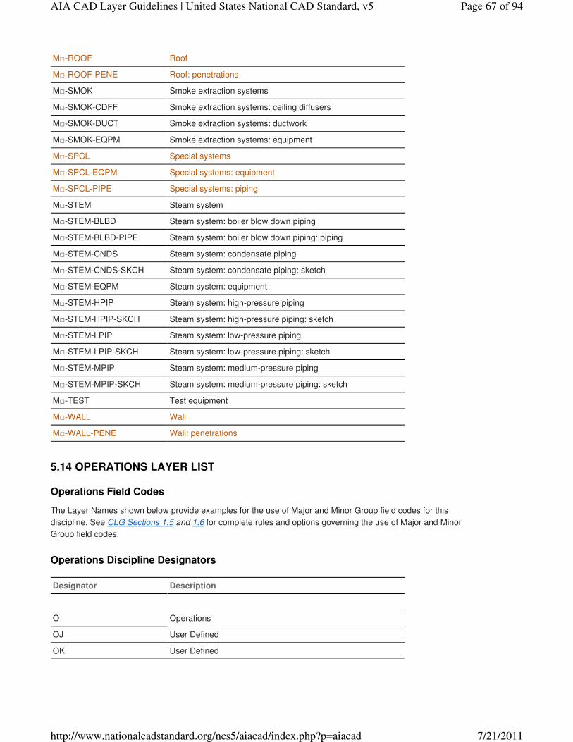
M□-ROOF Roof
M□-ROOF-PENE Roof: penetrations
M□-SMOK Smoke extraction systems
M□-SMOK-CDFF Smoke extraction systems: ceiling diffusers
M□-SMOK-DUCT Smoke extraction systems: ductwork
M□-SMOK-EQPM Smoke extraction systems: equipment
M□-SPCL Special systems
M□-SPCL-EQPM Special systems: equipment
M□-SPCL-PIPE Special systems: piping
M□-STEM Steam system
M□-STEM-BLBD Steam system: boiler blow down piping
M□-STEM-BLBD-PIPE Steam system: boiler blow down piping: piping
M□-STEM-CNDS Steam system: condensate piping
M□-STEM-CNDS-SKCH Steam system: condensate piping: sketch
M□-STEM-EQPM Steam system: equipment
M□-STEM-HPIP Steam system: high-pressure piping
M□-STEM-HPIP-SKCH Steam system: high-pressure piping: sketch
M□-STEM-LPIP Steam system: low-pressure piping
M□-STEM-LPIP-SKCH Steam system: low-pressure piping: sketch
M□-STEM-MPIP Steam system: medium-pressure piping
M□-STEM-MPIP-SKCH Steam system: medium-pressure piping: sketch
M□-TEST Test equipment
M□-WALL Wall
M□-WALL-PENE Wall: penetrations
Operations Field Codes
The Layer Names shown below provide examples for the use of Major and Minor Group field codes for this
discipline. See CLG Sections 1.5 and 1.6 for complete rules and options governing the use of Major and Minor
Group field codes.
Operations Discipline Designators
Designator Description
O Operations
OJ User Defined
OK User Defined
5.14 OPERATIONS LAYER LIST
Page 67 of 94AIA CAD Layer Guidelines | United States National CAD Standard, v5
7/21/2011http://www.nationalcadstandard.org/ncs5/aiacad/index.php?p=aiacad
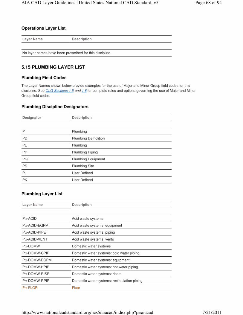
Operations Layer List
Layer Name Description
No layer names have been prescribed for this discipline.
Plumbing Field Codes
The Layer Names shown below provide examples for the use of Major and Minor Group field codes for this
discipline. See CLG Sections 1.5 and 1.6 for complete rules and options governing the use of Major and Minor
Group field codes.
Plumbing Discipline Designators
Designator Description
P Plumbing
PD Plumbing Demolition
PL Plumbing
PP Plumbing Piping
PQ Plumbing Equipment
PS Plumbing Site
PJ User Defined
PK User Defined
Plumbing Layer List
Layer Name Description
P□-ACID Acid waste systems
P□-ACID-EQPM Acid waste systems: equipment
P□-ACID-PIPE Acid waste systems: piping
P□-ACID-VENT Acid waste systems: vents
P□-DOMW Domestic water systems
P□-DOMW-CPIP Domestic water systems: cold water piping
P□-DOMW-EQPM Domestic water systems: equipment
P□-DOMW-HPIP Domestic water systems: hot water piping
P□-DOMW-RISR Domestic water systems: risers
P□-DOMW-RPIP Domestic water systems: recirculation piping
P□-FLOR Floor
5.15 PLUMBING LAYER LIST
Page 68 of 94AIA CAD Layer Guidelines | United States National CAD Standard, v5
7/21/2011http://www.nationalcadstandard.org/ncs5/aiacad/index.php?p=aiacad
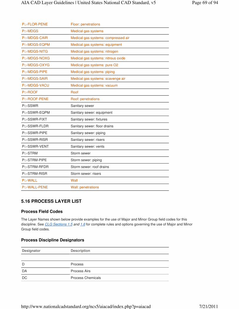
P□-FLOR-PENE Floor: penetrations
P□-MDGS Medical gas systems
P□-MDGS-CAIR Medical gas systems: compressed air
P□-MDGS-EQPM Medical gas systems: equipment
P□-MDGS-NITG Medical gas systems: nitrogen
P□-MDGS-NOXG Medical gas systems: nitrous oxide
P□-MDGS-OXYG Medical gas systems: pure O2
P□-MDGS-PIPE Medical gas systems: piping
P□-MDGS-SAIR Medical gas systems: scavenge air
P□-MDGS-VACU Medical gas systems: vacuum
P□-ROOF Roof
P□-ROOF-PENE Roof: penetrations
P□-SSWR Sanitary sewer
P□-SSWR-EQPM Sanitary sewer: equipment
P□-SSWR-FIXT Sanitary sewer: fixtures
P□-SSWR-FLDR Sanitary sewer: floor drains
P□-SSWR-PIPE Sanitary sewer: piping
P□-SSWR-RISR Sanitary sewer: risers
P□-SSWR-VENT Sanitary sewer: vents
P□-STRM Storm sewer
P□-STRM-PIPE Storm sewer: piping
P□-STRM-RFDR Storm sewer: roof drains
P□-STRM-RISR Storm sewer: risers
P□-WALL Wall
P□-WALL-PENE Wall: penetrations
Process Field Codes
The Layer Names shown below provide examples for the use of Major and Minor Group field codes for this
discipline. See CLG Sections 1.5 and 1.6 for complete rules and options governing the use of Major and Minor
Group field codes.
Process Discipline Designators
Designator Description
D Process
DA Process Airs
DC Process Chemicals
5.16 PROCESS LAYER LIST
Page 69 of 94AIA CAD Layer Guidelines | United States National CAD Standard, v5
7/21/2011http://www.nationalcadstandard.org/ncs5/aiacad/index.php?p=aiacad
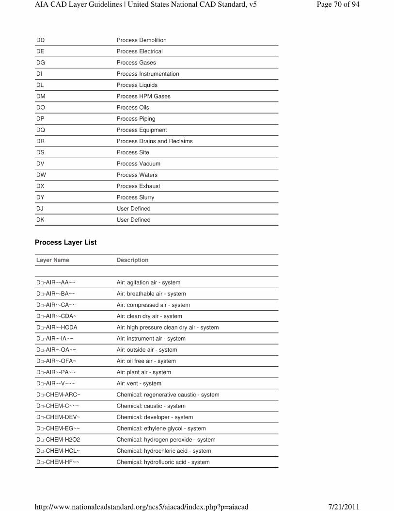
DD Process Demolition
DE Process Electrical
DG Process Gases
DI Process Instrumentation
DL Process Liquids
DM Process HPM Gases
DO Process Oils
DP Process Piping
DQ Process Equipment
DR Process Drains and Reclaims
DS Process Site
DV Process Vacuum
DW Process Waters
DX Process Exhaust
DY Process Slurry
DJ User Defined
DK User Defined
Process Layer List
Layer Name Description
D□-AIR~-AA~~ Air: agitation air - system
D□-AIR~-BA~~ Air: breathable air - system
D□-AIR~-CA~~ Air: compressed air - system
D□-AIR~-CDA~ Air: clean dry air - system
D□-AIR~-HCDA Air: high pressure clean dry air - system
D□-AIR~-IA~~ Air: instrument air - system
D□-AIR~-OA~~ Air: outside air - system
D□-AIR~-OFA~ Air: oil free air - system
D□-AIR~-PA~~ Air: plant air - system
D□-AIR~-V~~~ Air: vent - system
D□-CHEM-ARC~ Chemical: regenerative caustic - system
D□-CHEM-C~~~ Chemical: caustic - system
D□-CHEM-DEV~ Chemical: developer - system
D□-CHEM-EG~~ Chemical: ethylene glycol - system
D□-CHEM-H2O2 Chemical: hydrogen peroxide - system
D□-CHEM-HCL~ Chemical: hydrochloric acid - system
D□-CHEM-HF~~ Chemical: hydrofluoric acid - system
Page 70 of 94AIA CAD Layer Guidelines | United States National CAD Standard, v5
7/21/2011http://www.nationalcadstandard.org/ncs5/aiacad/index.php?p=aiacad
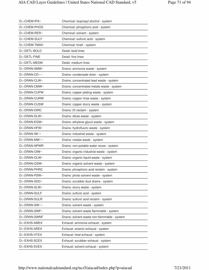
D□-CHEM-IPA~ Chemical: isopropyl alcohol - system
D□-CHEM-PHOS Chemical: phosphoric acid - system
D□-CHEM-RER~ Chemical: solvent - system
D□-CHEM-SULF Chemical: sulfuric acid - system
D□-CHEM-TMAH Chemical: tmah - system
D□-DETL-BOLD Detail: bold lines
D□-DETL-FINE Detail: fine lines
D□-DETL-MEDM Detail: medium lines
D□-DRAN-AMW~ Drains: ammonia waste - system
D□-DRAN-CD~~ Drains: condensate drain - system
D□-DRAN-CLW~ Drains: concentrated lead waste - system
D□-DRAN-CMW~ Drains: concentrated metals waste - system
D□-DRAN-CUPW Drains: copper plating waste - system
D□-DRAN-CURW Drains: copper rinse waste - system
D□-DRAN-CUSW Drains: copper slurry waste - system
D□-DRAN-DIRC Drains: DI reclaim - system
D□-DRAN-DLW~ Drains: dilute waste - system
D□-DRAN-EGW~ Drains: ethylene glycol waste - system
D□-DRAN-HFW~ Drains: hydrofluoric waste - system
D□-DRAN-IW~~ Drains: industrial waste - system
D□-DRAN-MW~~ Drains: metals waste - system
D□-DRAN-NPWR Drains: non-potable water reuse - system
D□-DRAN-OIW~ Drains: organic industrial waste - system
D□-DRAN-OLW~ Drains: organic liquid waste - system
D□-DRAN-OSW~ Drains: organic solvent waste - system
D□-DRAN-PHRC Drains: phosphoric acid reclaim - system
D□-DRAN-PSW~ Drains: photo solvent waste - system
D□-DRAN-SDD~ Drains: scrubber duct drains - system
D□-DRAN-SLW~ Drains: slurry waste - system
D□-DRAN-SULF Drains: sulfuric acid - system
D□-DRAN-SULR Drains: sulfuric acid reclaim - system
D□-DRAN-SW~~ Drains: solvent waste - system
D□-DRAN-SWF~ Drains: solvent waste flammable - system
D□-DRAN-SWNF Drains: solvent waste non-flammable - system
D□-EXHS-AMEX Exhaust: ammonia exhaust - system
D□-EXHS-AREX Exhaust: arsenic exhaust - system
D□-EXHS-HTEX Exhaust: heat exhaust - system
D□-EXHS-SCEX Exhaust: scrubber exhaust - system
D□-EXHS-SVEX Exhaust: solvent exhaust - system
Page 71 of 94AIA CAD Layer Guidelines | United States National CAD Standard, v5
7/21/2011http://www.nationalcadstandard.org/ncs5/aiacad/index.php?p=aiacad

D□-GAS~-AR~~ Gas: argon - system
D□-GAS~-ARB~ Gas: argon bulk - system
D□-GAS~-BUT~ Gas: butane - system
D□-GAS~-CLG~ Gas: chlorine gas - system
D□-GAS~-H2~~ Gas: hydrogen - system
D□-GAS~-HE~~ Gas: helium - system
D□-GAS~-HPN2 Gas: high purity nitrogen - system
D□-GAS~-HPO2 Gas: high purity oxygen - system
D□-GAS~-LCHE Gas: leak check helium - system
D□-GAS~-N2~~ Gas: nitrogen - system
D□-GAS~-N2O~ Gas: nitrous oxide - system
D□-GAS~-NG~~ Gas: natural gas - system
D□-GAS~-O2~~ Gas: oxygen - system
D□-GAS~-PRO~ Gas: propane - system
D□-GAS~-SG~~ Gas: specialty gas - system
D□-GAS~-UN2~ Gas: utility nitrogen - system
D□-GAS~-VN2~ Gas: venturi nitrogen - system
D□-GAS~-WAR~ Gas: weld argon - system
D□-LIQD-LPG~ Liquid: liquid petroleum gas - system
D□-OIL~-LO~~ Oil: lube oil - system
D□-PIPE Piping
D□-PIPE-CNTR Piping: center
D□-PIPE-EQPM Piping: equipment
D□-PIPE-HDLN Piping: hidden line
D□-PIPE-MISC Piping: miscellaneous
D□-PIPE-PATT Piping: texture and hatch patterns
D□-PIPE-UGND Piping: underground
D□-SLUR-SLR~ Slurry: slurry return - system
D□-SLUR-SLS~ Slurry: slurry supply - system
D□-VACU-CLV~ Vacuum: chlorine vacuum - system
D□-VACU-CV~~ Vacuum: chemical vacuum - system
D□-VACU-EV~~ Vacuum: equipment vacuum - system
D□-VACU-HV~~ Vacuum: house vacuum - system
D□-VACU-HVA~ Vacuum: arsenic house vacuum - system
D□-VACU-PV~~ Vacuum: vacuum - system
D□-WATR-BFW~ Water: boiler feed water - system
D□-WATR-DIR~ Water: deionized water return - system
D□-WATR-DIS~ Water: deionized water supply - system
D□-WATR-DIWP Water: DI polishing loop - system
Page 72 of 94AIA CAD Layer Guidelines | United States National CAD Standard, v5
7/21/2011http://www.nationalcadstandard.org/ncs5/aiacad/index.php?p=aiacad
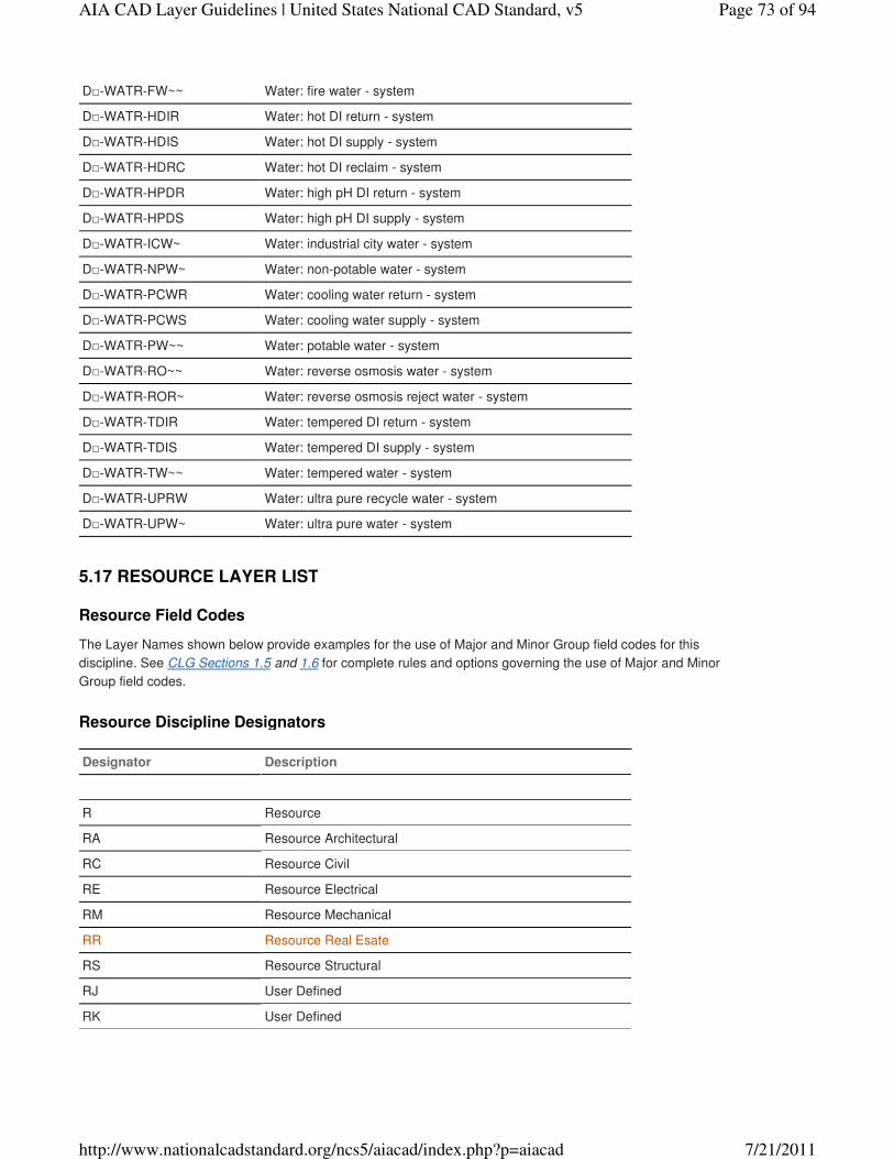
D□-WATR-FW~~ Water: fire water - system
D□-WATR-HDIR Water: hot DI return - system
D□-WATR-HDIS Water: hot DI supply - system
D□-WATR-HDRC Water: hot DI reclaim - system
D□-WATR-HPDR Water: high pH DI return - system
D□-WATR-HPDS Water: high pH DI supply - system
D□-WATR-ICW~ Water: industrial city water - system
D□-WATR-NPW~ Water: non-potable water - system
D□-WATR-PCWR Water: cooling water return - system
D□-WATR-PCWS Water: cooling water supply - system
D□-WATR-PW~~ Water: potable water - system
D□-WATR-RO~~ Water: reverse osmosis water - system
D□-WATR-ROR~ Water: reverse osmosis reject water - system
D□-WATR-TDIR Water: tempered DI return - system
D□-WATR-TDIS Water: tempered DI supply - system
D□-WATR-TW~~ Water: tempered water - system
D□-WATR-UPRW Water: ultra pure recycle water - system
D□-WATR-UPW~ Water: ultra pure water - system
Resource Field Codes
The Layer Names shown below provide examples for the use of Major and Minor Group field codes for this
discipline. See CLG Sections 1.5 and 1.6 for complete rules and options governing the use of Major and Minor
Group field codes.
Resource Discipline Designators
Designator Description
R Resource
RA Resource Architectural
RC Resource Civil
RE Resource Electrical
RM Resource Mechanical
RR Resource Real Esate
RS Resource Structural
RJ User Defined
RK User Defined
5.17 RESOURCE LAYER LIST
Page 73 of 94AIA CAD Layer Guidelines | United States National CAD Standard, v5
7/21/2011http://www.nationalcadstandard.org/ncs5/aiacad/index.php?p=aiacad
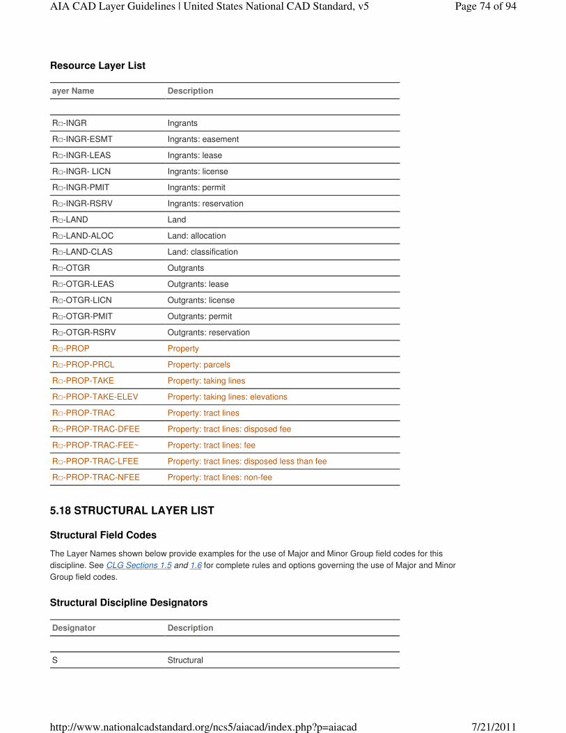
Resource Layer List
ayer Name Description
R□-INGR Ingrants
R□-INGR-ESMT Ingrants: easement
R□-INGR-LEAS Ingrants: lease
R□-INGR- LICN Ingrants: license
R□-INGR-PMIT Ingrants: permit
R□-INGR-RSRV Ingrants: reservation
R□-LAND Land
R□-LAND-ALOC Land: allocation
R□-LAND-CLAS Land: classification
R□-OTGR Outgrants
R□-OTGR-LEAS Outgrants: lease
R□-OTGR-LICN Outgrants: license
R□-OTGR-PMIT Outgrants: permit
R□-OTGR-RSRV Outgrants: reservation
R□-PROP Property
R□-PROP-PRCL Property: parcels
R□-PROP-TAKE Property: taking lines
R□-PROP-TAKE-ELEV Property: taking lines: elevations
R□-PROP-TRAC Property: tract lines
R□-PROP-TRAC-DFEE Property: tract lines: disposed fee
R□-PROP-TRAC-FEE~ Property: tract lines: fee
R□-PROP-TRAC-LFEE Property: tract lines: disposed less than fee
R□-PROP-TRAC-NFEE Property: tract lines: non-fee
Structural Field Codes
The Layer Names shown below provide examples for the use of Major and Minor Group field codes for this
discipline. See CLG Sections 1.5 and 1.6 for complete rules and options governing the use of Major and Minor
Group field codes.
Structural Discipline Designators
Designator Description
S Structural
5.18 STRUCTURAL LAYER LIST
Page 74 of 94AIA CAD Layer Guidelines | United States National CAD Standard, v5
7/21/2011http://www.nationalcadstandard.org/ncs5/aiacad/index.php?p=aiacad
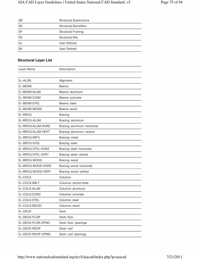
SB Structural Substructure
SD Structural Demolition
SF Structural Framing
SS Structural Site
SJ User Defined
SK User Defined
Structural Layer List
Layer Name Description
S□-ALGN Alignment
S□-BEAM Beams
S□-BEAM-ALUM Beams: aluminum
S□-BEAM-CONC Beams: concrete
S□-BEAM-STEL Beams: steel
S□-BEAM-WOOD Beams: wood
S□-BRCG Bracing
S□-BRCG-ALUM Bracing: aluminum
S□-BRCG-ALUM-HORZ Bracing: aluminum: horizontal
S□-BRCG-ALUM-VERT Bracing: aluminum: vertical
S□-BRCG-METL Bracing: metal
S□-BRCG-STEL Bracing: steel
S□-BRCG-STEL-HORZ Bracing: steel: horizontal
S□-BRCG-STEL-VERT Bracing: steel: vertical
S□-BRCG-WOOD Bracing: wood
S□-BRCG-WOOD-HORZ Bracing: wood: horizontal
S□-BRCG-WOOD-VERT Bracing: wood: vertical
S□-COLS Columns
S□-COLS-ABLT Columns: anchor bolts
S□-COLS-ALUM Columns: aluminum
S□-COLS-CONC Columns: concrete
S□-COLS-STEL Columns: steel
S□-COLS-WOOD Columns: wood
S□-DECK Deck
S□-DECK-FLOR Deck: floor
S□-DECK-FLOR-OPNG Deck: floor: openings
S□-DECK-ROOF Deck: roof
S□-DECK-ROOF-OPNG Deck: roof: openings
Page 75 of 94AIA CAD Layer Guidelines | United States National CAD Standard, v5
7/21/2011http://www.nationalcadstandard.org/ncs5/aiacad/index.php?p=aiacad
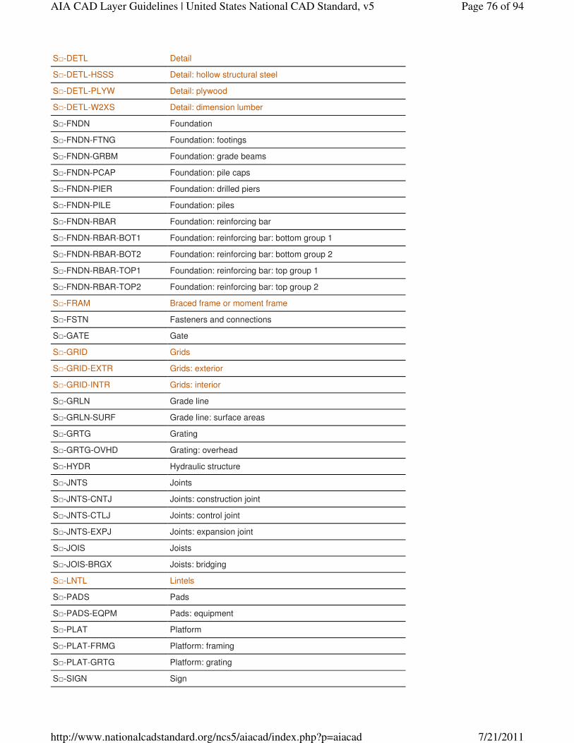
S□-DETL Detail
S□-DETL-HSSS Detail: hollow structural steel
S□-DETL-PLYW Detail: plywood
S□-DETL-W2XS Detail: dimension lumber
S□-FNDN Foundation
S□-FNDN-FTNG Foundation: footings
S□-FNDN-GRBM Foundation: grade beams
S□-FNDN-PCAP Foundation: pile caps
S□-FNDN-PIER Foundation: drilled piers
S□-FNDN-PILE Foundation: piles
S□-FNDN-RBAR Foundation: reinforcing bar
S□-FNDN-RBAR-BOT1 Foundation: reinforcing bar: bottom group 1
S□-FNDN-RBAR-BOT2 Foundation: reinforcing bar: bottom group 2
S□-FNDN-RBAR-TOP1 Foundation: reinforcing bar: top group 1
S□-FNDN-RBAR-TOP2 Foundation: reinforcing bar: top group 2
S□-FRAM Braced frame or moment frame
S□-FSTN Fasteners and connections
S□-GATE Gate
S□-GRID Grids
S□-GRID-EXTR Grids: exterior
S□-GRID-INTR Grids: interior
S□-GRLN Grade line
S□-GRLN-SURF Grade line: surface areas
S□-GRTG Grating
S□-GRTG-OVHD Grating: overhead
S□-HYDR Hydraulic structure
S□-JNTS Joints
S□-JNTS-CNTJ Joints: construction joint
S□-JNTS-CTLJ Joints: control joint
S□-JNTS-EXPJ Joints: expansion joint
S□-JOIS Joists
S□-JOIS-BRGX Joists: bridging
S□-LNTL Lintels
S□-PADS Pads
S□-PADS-EQPM Pads: equipment
S□-PLAT Platform
S□-PLAT-FRMG Platform: framing
S□-PLAT-GRTG Platform: grating
S□-SIGN Sign
Page 76 of 94AIA CAD Layer Guidelines | United States National CAD Standard, v5
7/21/2011http://www.nationalcadstandard.org/ncs5/aiacad/index.php?p=aiacad
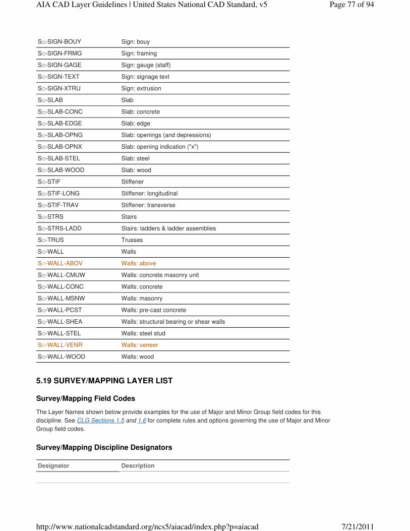
S□-SIGN-BOUY Sign: bouy
S□-SIGN-FRMG Sign: framing
S□-SIGN-GAGE Sign: gauge (staff)
S□-SIGN-TEXT Sign: signage text
S□-SIGN-XTRU Sign: extrusion
S□-SLAB Slab
S□-SLAB-CONC Slab: concrete
S□-SLAB-EDGE Slab: edge
S□-SLAB-OPNG Slab: openings (and depressions)
S□-SLAB-OPNX Slab: opening indication ("x")
S□-SLAB-STEL Slab: steel
S□-SLAB-WOOD Slab: wood
S□-STIF Stiffener
S□-STIF-LONG Stiffener: longitudinal
S□-STIF-TRAV Stiffener: transverse
S□-STRS Stairs
S□-STRS-LADD Stairs: ladders & ladder assemblies
S□-TRUS Trusses
S□-WALL Walls
S□-WALL-ABOV Walls: above
S□-WALL-CMUW Walls: concrete masonry unit
S□-WALL-CONC Walls: concrete
S□-WALL-MSNW Walls: masonry
S□-WALL-PCST Walls: pre-cast concrete
S□-WALL-SHEA Walls: structural bearing or shear walls
S□-WALL-STEL Walls: steel stud
S□-WALL-VENR Walls: veneer
S□-WALL-WOOD Walls: wood
Survey/Mapping Field Codes
The Layer Names shown below provide examples for the use of Major and Minor Group field codes for this
discipline. See CLG Sections 1.5 and 1.6 for complete rules and options governing the use of Major and Minor
Group field codes.
Survey/Mapping Discipline Designators
Designator Description
5.19 SURVEY/MAPPING LAYER LIST
Page 77 of 94AIA CAD Layer Guidelines | United States National CAD Standard, v5
7/21/2011http://www.nationalcadstandard.org/ncs5/aiacad/index.php?p=aiacad
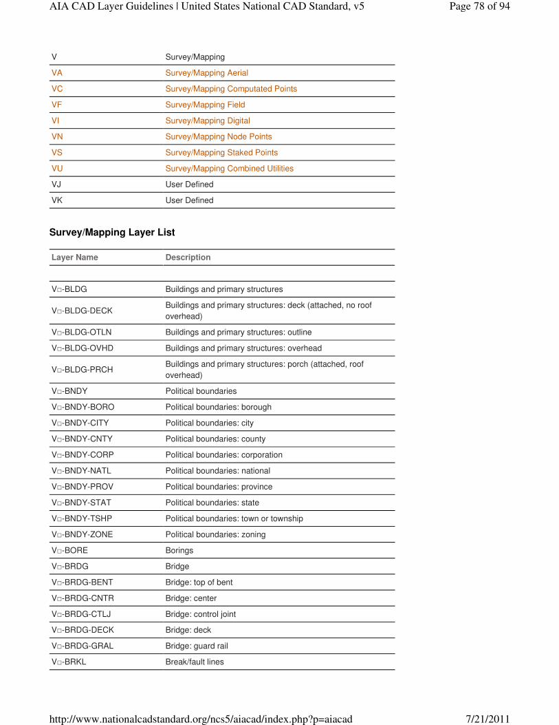
V Survey/Mapping
VA Survey/Mapping Aerial
VC Survey/Mapping Computated Points
VF Survey/Mapping Field
VI Survey/Mapping Digital
VN Survey/Mapping Node Points
VS Survey/Mapping Staked Points
VU Survey/Mapping Combined Utilities
VJ User Defined
VK User Defined
Survey/Mapping Layer List
Layer Name Description
V□-BLDG Buildings and primary structures
V□-BLDG-DECKBuildings and primary structures: deck (attached, no roof
overhead)
V□-BLDG-OTLN Buildings and primary structures: outline
V□-BLDG-OVHD Buildings and primary structures: overhead
V□-BLDG-PRCHBuildings and primary structures: porch (attached, roof
overhead)
V□-BNDY Political boundaries
V□-BNDY-BORO Political boundaries: borough
V□-BNDY-CITY Political boundaries: city
V□-BNDY-CNTY Political boundaries: county
V□-BNDY-CORP Political boundaries: corporation
V□-BNDY-NATL Political boundaries: national
V□-BNDY-PROV Political boundaries: province
V□-BNDY-STAT Political boundaries: state
V□-BNDY-TSHP Political boundaries: town or township
V□-BNDY-ZONE Political boundaries: zoning
V□-BORE Borings
V□-BRDG Bridge
V□-BRDG-BENT Bridge: top of bent
V□-BRDG-CNTR Bridge: center
V□-BRDG-CTLJ Bridge: control joint
V□-BRDG-DECK Bridge: deck
V□-BRDG-GRAL Bridge: guard rail
V□-BRKL Break/fault lines
Page 78 of 94AIA CAD Layer Guidelines | United States National CAD Standard, v5
7/21/2011http://www.nationalcadstandard.org/ncs5/aiacad/index.php?p=aiacad
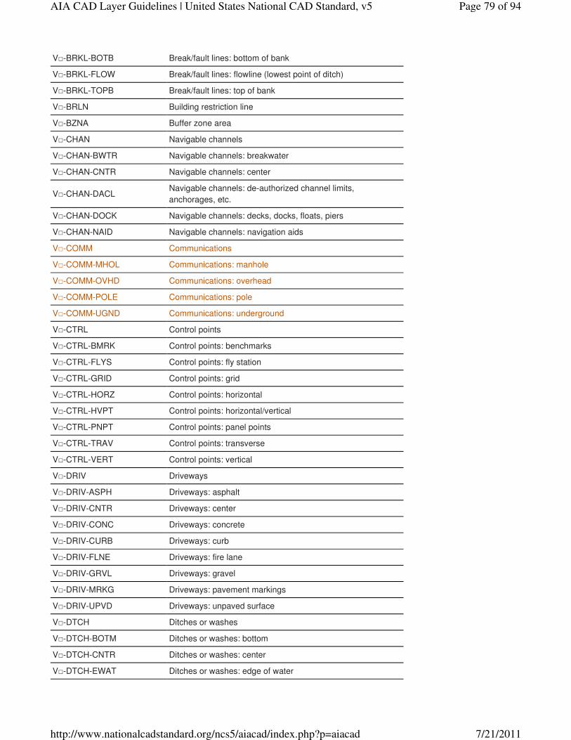
V□-BRKL-BOTB Break/fault lines: bottom of bank
V□-BRKL-FLOW Break/fault lines: flowline (lowest point of ditch)
V□-BRKL-TOPB Break/fault lines: top of bank
V□-BRLN Building restriction line
V□-BZNA Buffer zone area
V□-CHAN Navigable channels
V□-CHAN-BWTR Navigable channels: breakwater
V□-CHAN-CNTR Navigable channels: center
V□-CHAN-DACLNavigable channels: de-authorized channel limits,
anchorages, etc.
V□-CHAN-DOCK Navigable channels: decks, docks, floats, piers
V□-CHAN-NAID Navigable channels: navigation aids
V□-COMM Communications
V□-COMM-MHOL Communications: manhole
V□-COMM-OVHD Communications: overhead
V□-COMM-POLE Communications: pole
V□-COMM-UGND Communications: underground
V□-CTRL Control points
V□-CTRL-BMRK Control points: benchmarks
V□-CTRL-FLYS Control points: fly station
V□-CTRL-GRID Control points: grid
V□-CTRL-HORZ Control points: horizontal
V□-CTRL-HVPT Control points: horizontal/vertical
V□-CTRL-PNPT Control points: panel points
V□-CTRL-TRAV Control points: transverse
V□-CTRL-VERT Control points: vertical
V□-DRIV Driveways
V□-DRIV-ASPH Driveways: asphalt
V□-DRIV-CNTR Driveways: center
V□-DRIV-CONC Driveways: concrete
V□-DRIV-CURB Driveways: curb
V□-DRIV-FLNE Driveways: fire lane
V□-DRIV-GRVL Driveways: gravel
V□-DRIV-MRKG Driveways: pavement markings
V□-DRIV-UPVD Driveways: unpaved surface
V□-DTCH Ditches or washes
V□-DTCH-BOTM Ditches or washes: bottom
V□-DTCH-CNTR Ditches or washes: center
V□-DTCH-EWAT Ditches or washes: edge of water
Page 79 of 94AIA CAD Layer Guidelines | United States National CAD Standard, v5
7/21/2011http://www.nationalcadstandard.org/ncs5/aiacad/index.php?p=aiacad
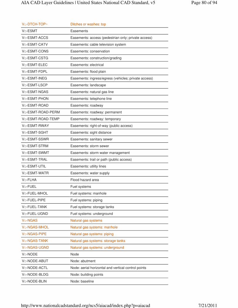
V□-DTCH-TOP~ Ditches or washes: top
V□-ESMT Easements
V□-ESMT-ACCS Easements: access (pedestrian only; private access)
V□-ESMT-CATV Easements: cable television system
V□-ESMT-CONS Easements: conservation
V□-ESMT-CSTG Easements: construction/grading
V□-ESMT-ELEC Easements: electrical
V□-ESMT-FDPL Easements: flood plain
V□-ESMT-INEG Easements: ingress/egress (vehicles; private access)
V□-ESMT-LSCP Easements: landscape
V□-ESMT-NGAS Easements: natural gas line
V□-ESMT-PHON Easements: telephone line
V□-ESMT-ROAD Easements: roadway
V□-ESMT-ROAD-PERM Easements: roadway: permanent
V□-ESMT-ROAD-TEMP Easements: roadway: temporary
V□-ESMT-RWAY Easements: right-of-way (public access)
V□-ESMT-SGHT Easements: sight distance
V□-ESMT-SSWR Easements: sanitary sewer
V□-ESMT-STRM Easements: storm sewer
V□-ESMT-SWMT Easements: storm water management
V□-ESMT-TRAL Easements: trail or path (public access)
V□-ESMT-UTIL Easements: utility lines
V□-ESMT-WATR Easements: water supply
V□-FLHA Flood hazard area
V□-FUEL Fuel systems
V□-FUEL-MHOL Fuel systems: manhole
V□-FUEL-PIPE Fuel systems: piping
V□-FUEL-TANK Fuel systems: storage tanks
V□-FUEL-UGND Fuel systems: underground
V□-NGAS Natural gas systems
V□-NGAS-MHOL Natural gas systems: manhole
V□-NGAS-PIPE Natural gas systems: piping
V□-NGAS-TANK Natural gas systems: storage tanks
V□-NGAS-UGND Natural gas systems: underground
V□-NODE Node
V□-NODE-ABUT Node: abutment
V□-NODE-ACTL Node: aerial horizontal and vertical control points
V□-NODE-BLDG Node: building points
V□-NODE-BLIN Node: baseline
Page 80 of 94AIA CAD Layer Guidelines | United States National CAD Standard, v5
7/21/2011http://www.nationalcadstandard.org/ncs5/aiacad/index.php?p=aiacad
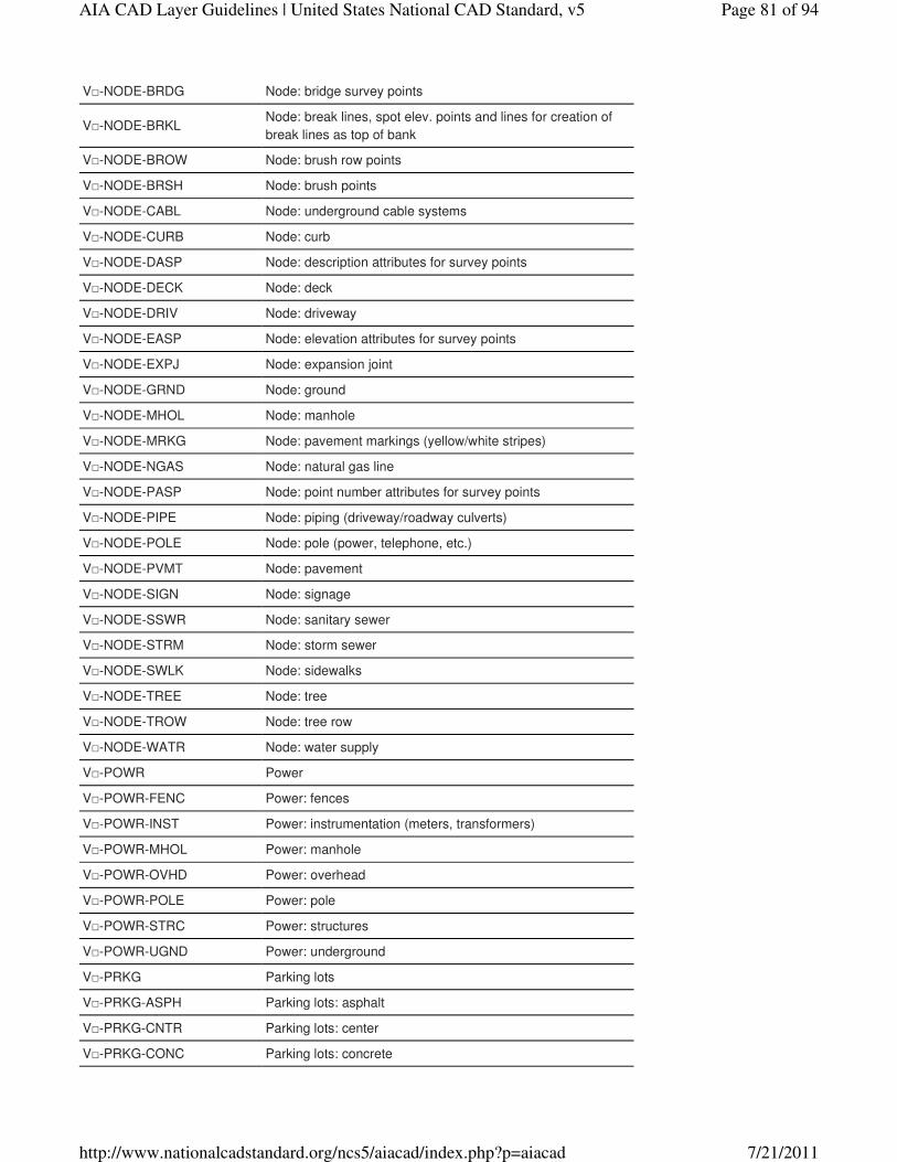
V□-NODE-BRDG Node: bridge survey points
V□-NODE-BRKLNode: break lines, spot elev. points and lines for creation of
break lines as top of bank
V□-NODE-BROW Node: brush row points
V□-NODE-BRSH Node: brush points
V□-NODE-CABL Node: underground cable systems
V□-NODE-CURB Node: curb
V□-NODE-DASP Node: description attributes for survey points
V□-NODE-DECK Node: deck
V□-NODE-DRIV Node: driveway
V□-NODE-EASP Node: elevation attributes for survey points
V□-NODE-EXPJ Node: expansion joint
V□-NODE-GRND Node: ground
V□-NODE-MHOL Node: manhole
V□-NODE-MRKG Node: pavement markings (yellow/white stripes)
V□-NODE-NGAS Node: natural gas line
V□-NODE-PASP Node: point number attributes for survey points
V□-NODE-PIPE Node: piping (driveway/roadway culverts)
V□-NODE-POLE Node: pole (power, telephone, etc.)
V□-NODE-PVMT Node: pavement
V□-NODE-SIGN Node: signage
V□-NODE-SSWR Node: sanitary sewer
V□-NODE-STRM Node: storm sewer
V□-NODE-SWLK Node: sidewalks
V□-NODE-TREE Node: tree
V□-NODE-TROW Node: tree row
V□-NODE-WATR Node: water supply
V□-POWR Power
V□-POWR-FENC Power: fences
V□-POWR-INST Power: instrumentation (meters, transformers)
V□-POWR-MHOL Power: manhole
V□-POWR-OVHD Power: overhead
V□-POWR-POLE Power: pole
V□-POWR-STRC Power: structures
V□-POWR-UGND Power: underground
V□-PRKG Parking lots
V□-PRKG-ASPH Parking lots: asphalt
V□-PRKG-CNTR Parking lots: center
V□-PRKG-CONC Parking lots: concrete
Page 81 of 94AIA CAD Layer Guidelines | United States National CAD Standard, v5
7/21/2011http://www.nationalcadstandard.org/ncs5/aiacad/index.php?p=aiacad
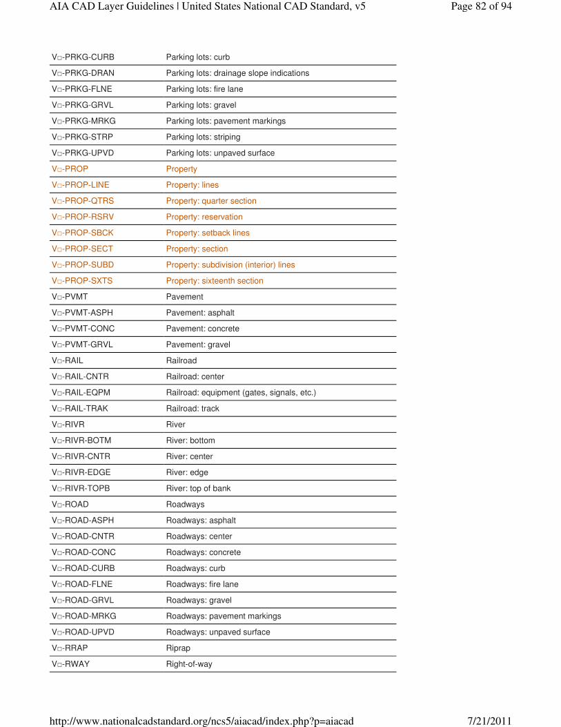
V□-PRKG-CURB Parking lots: curb
V□-PRKG-DRAN Parking lots: drainage slope indications
V□-PRKG-FLNE Parking lots: fire lane
V□-PRKG-GRVL Parking lots: gravel
V□-PRKG-MRKG Parking lots: pavement markings
V□-PRKG-STRP Parking lots: striping
V□-PRKG-UPVD Parking lots: unpaved surface
V□-PROP Property
V□-PROP-LINE Property: lines
V□-PROP-QTRS Property: quarter section
V□-PROP-RSRV Property: reservation
V□-PROP-SBCK Property: setback lines
V□-PROP-SECT Property: section
V□-PROP-SUBD Property: subdivision (interior) lines
V□-PROP-SXTS Property: sixteenth section
V□-PVMT Pavement
V□-PVMT-ASPH Pavement: asphalt
V□-PVMT-CONC Pavement: concrete
V□-PVMT-GRVL Pavement: gravel
V□-RAIL Railroad
V□-RAIL-CNTR Railroad: center
V□-RAIL-EQPM Railroad: equipment (gates, signals, etc.)
V□-RAIL-TRAK Railroad: track
V□-RIVR River
V□-RIVR-BOTM River: bottom
V□-RIVR-CNTR River: center
V□-RIVR-EDGE River: edge
V□-RIVR-TOPB River: top of bank
V□-ROAD Roadways
V□-ROAD-ASPH Roadways: asphalt
V□-ROAD-CNTR Roadways: center
V□-ROAD-CONC Roadways: concrete
V□-ROAD-CURB Roadways: curb
V□-ROAD-FLNE Roadways: fire lane
V□-ROAD-GRVL Roadways: gravel
V□-ROAD-MRKG Roadways: pavement markings
V□-ROAD-UPVD Roadways: unpaved surface
V□-RRAP Riprap
V□-RWAY Right-of-way
Page 82 of 94AIA CAD Layer Guidelines | United States National CAD Standard, v5
7/21/2011http://www.nationalcadstandard.org/ncs5/aiacad/index.php?p=aiacad
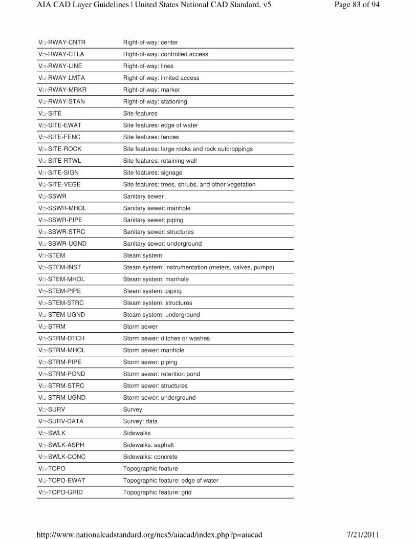
V□-RWAY-CNTR Right-of-way: center
V□-RWAY-CTLA Right-of-way: controlled access
V□-RWAY-LINE Right-of-way: lines
V□-RWAY-LMTA Right-of-way: limited access
V□-RWAY-MRKR Right-of-way: marker
V□-RWAY-STAN Right-of-way: stationing
V□-SITE Site features
V□-SITE-EWAT Site features: edge of water
V□-SITE-FENC Site features: fences
V□-SITE-ROCK Site features: large rocks and rock outcroppings
V□-SITE-RTWL Site features: retaining wall
V□-SITE-SIGN Site features: signage
V□-SITE-VEGE Site features: trees, shrubs, and other vegetation
V□-SSWR Sanitary sewer
V□-SSWR-MHOL Sanitary sewer: manhole
V□-SSWR-PIPE Sanitary sewer: piping
V□-SSWR-STRC Sanitary sewer: structures
V□-SSWR-UGND Sanitary sewer: underground
V□-STEM Steam system
V□-STEM-INST Steam system: instrumentation (meters, valves, pumps)
V□-STEM-MHOL Steam system: manhole
V□-STEM-PIPE Steam system: piping
V□-STEM-STRC Steam system: structures
V□-STEM-UGND Steam system: underground
V□-STRM Storm sewer
V□-STRM-DTCH Storm sewer: ditches or washes
V□-STRM-MHOL Storm sewer: manhole
V□-STRM-PIPE Storm sewer: piping
V□-STRM-POND Storm sewer: retention pond
V□-STRM-STRC Storm sewer: structures
V□-STRM-UGND Storm sewer: underground
V□-SURV Survey
V□-SURV-DATA Survey: data
V□-SWLK Sidewalks
V□-SWLK-ASPH Sidewalks: asphalt
V□-SWLK-CONC Sidewalks: concrete
V□-TOPO Topographic feature
V□-TOPO-EWAT Topographic feature: edge of water
V□-TOPO-GRID Topographic feature: grid
Page 83 of 94AIA CAD Layer Guidelines | United States National CAD Standard, v5
7/21/2011http://www.nationalcadstandard.org/ncs5/aiacad/index.php?p=aiacad
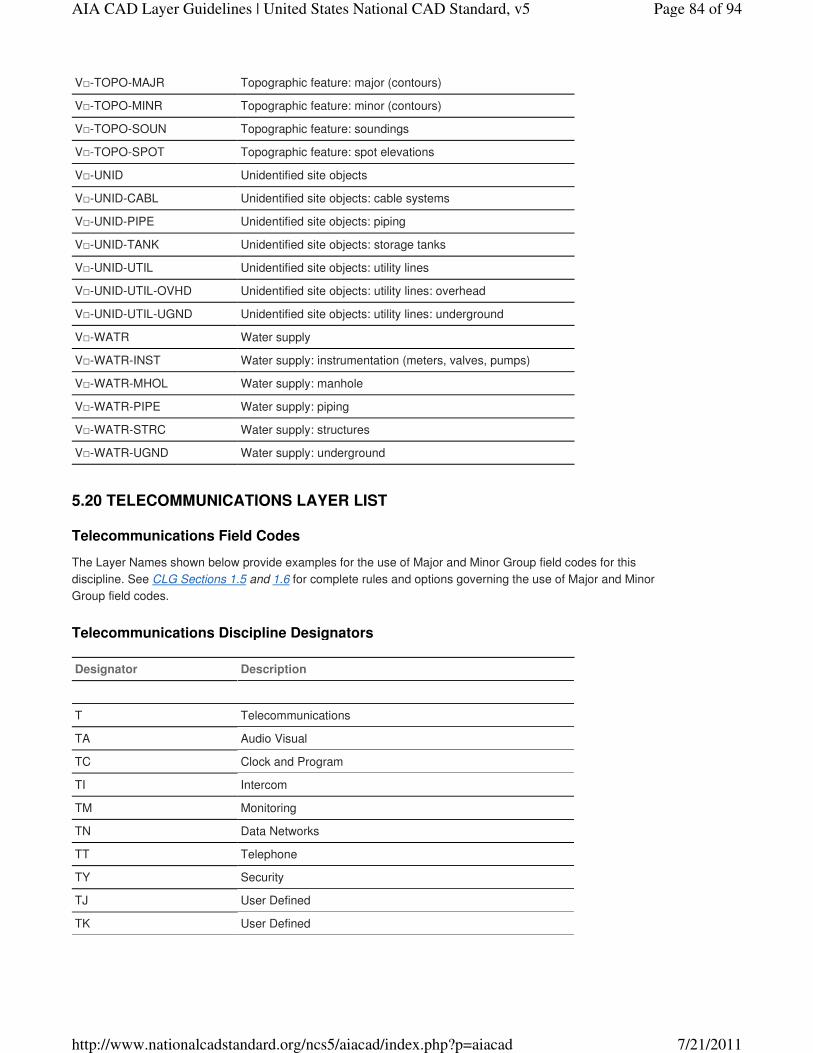
V□-TOPO-MAJR Topographic feature: major (contours)
V□-TOPO-MINR Topographic feature: minor (contours)
V□-TOPO-SOUN Topographic feature: soundings
V□-TOPO-SPOT Topographic feature: spot elevations
V□-UNID Unidentified site objects
V□-UNID-CABL Unidentified site objects: cable systems
V□-UNID-PIPE Unidentified site objects: piping
V□-UNID-TANK Unidentified site objects: storage tanks
V□-UNID-UTIL Unidentified site objects: utility lines
V□-UNID-UTIL-OVHD Unidentified site objects: utility lines: overhead
V□-UNID-UTIL-UGND Unidentified site objects: utility lines: underground
V□-WATR Water supply
V□-WATR-INST Water supply: instrumentation (meters, valves, pumps)
V□-WATR-MHOL Water supply: manhole
V□-WATR-PIPE Water supply: piping
V□-WATR-STRC Water supply: structures
V□-WATR-UGND Water supply: underground
Telecommunications Field Codes
The Layer Names shown below provide examples for the use of Major and Minor Group field codes for this
discipline. See CLG Sections 1.5 and 1.6 for complete rules and options governing the use of Major and Minor
Group field codes.
Telecommunications Discipline Designators
Designator Description
T Telecommunications
TA Audio Visual
TC Clock and Program
TI Intercom
TM Monitoring
TN Data Networks
TT Telephone
TY Security
TJ User Defined
TK User Defined
5.20 TELECOMMUNICATIONS LAYER LIST
Page 84 of 94AIA CAD Layer Guidelines | United States National CAD Standard, v5
7/21/2011http://www.nationalcadstandard.org/ncs5/aiacad/index.php?p=aiacad
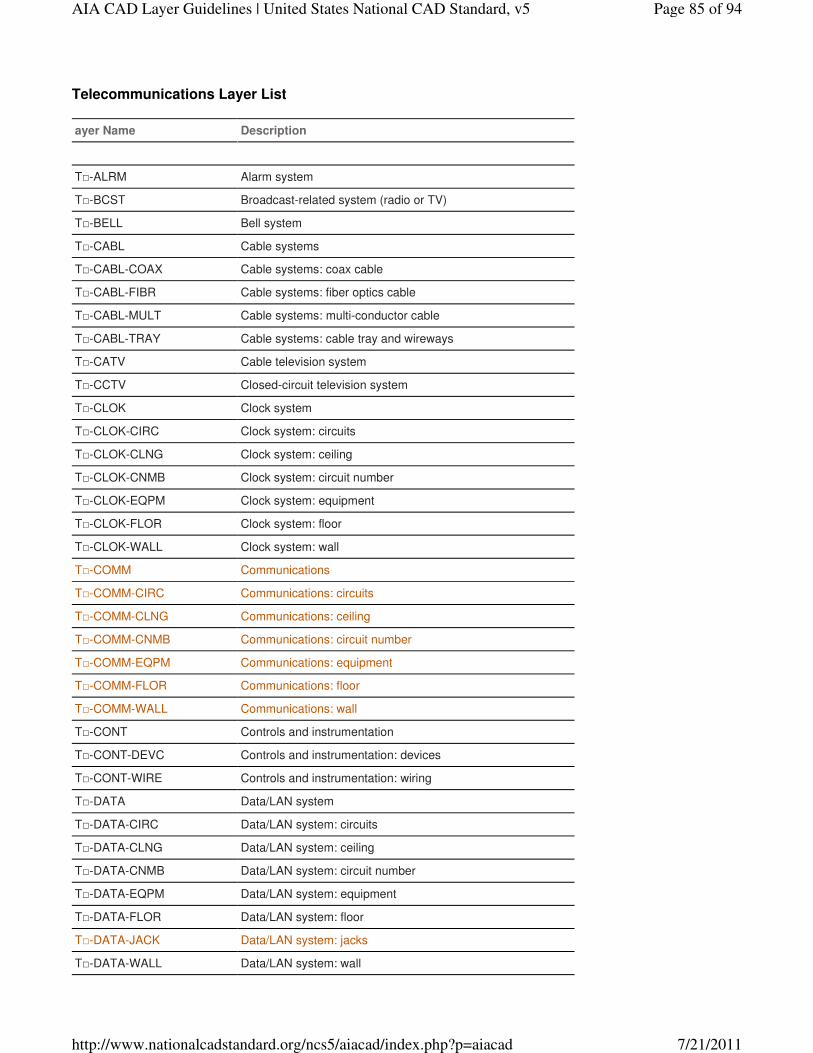
Telecommunications Layer List
ayer Name Description
T□-ALRM Alarm system
T□-BCST Broadcast-related system (radio or TV)
T□-BELL Bell system
T□-CABL Cable systems
T□-CABL-COAX Cable systems: coax cable
T□-CABL-FIBR Cable systems: fiber optics cable
T□-CABL-MULT Cable systems: multi-conductor cable
T□-CABL-TRAY Cable systems: cable tray and wireways
T□-CATV Cable television system
T□-CCTV Closed-circuit television system
T□-CLOK Clock system
T□-CLOK-CIRC Clock system: circuits
T□-CLOK-CLNG Clock system: ceiling
T□-CLOK-CNMB Clock system: circuit number
T□-CLOK-EQPM Clock system: equipment
T□-CLOK-FLOR Clock system: floor
T□-CLOK-WALL Clock system: wall
T□-COMM Communications
T□-COMM-CIRC Communications: circuits
T□-COMM-CLNG Communications: ceiling
T□-COMM-CNMB Communications: circuit number
T□-COMM-EQPM Communications: equipment
T□-COMM-FLOR Communications: floor
T□-COMM-WALL Communications: wall
T□-CONT Controls and instrumentation
T□-CONT-DEVC Controls and instrumentation: devices
T□-CONT-WIRE Controls and instrumentation: wiring
T□-DATA Data/LAN system
T□-DATA-CIRC Data/LAN system: circuits
T□-DATA-CLNG Data/LAN system: ceiling
T□-DATA-CNMB Data/LAN system: circuit number
T□-DATA-EQPM Data/LAN system: equipment
T□-DATA-FLOR Data/LAN system: floor
T□-DATA-JACK Data/LAN system: jacks
T□-DATA-WALL Data/LAN system: wall
Page 85 of 94AIA CAD Layer Guidelines | United States National CAD Standard, v5
7/21/2011http://www.nationalcadstandard.org/ncs5/aiacad/index.php?p=aiacad
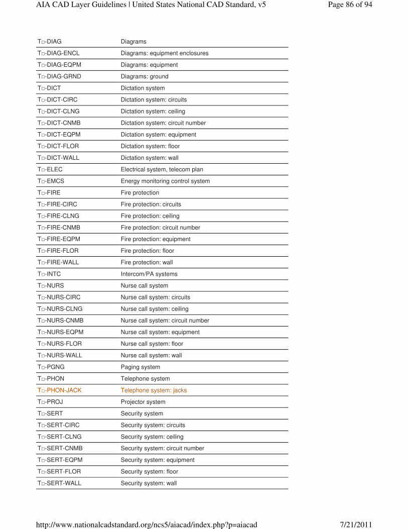
T□-DIAG Diagrams
T□-DIAG-ENCL Diagrams: equipment enclosures
T□-DIAG-EQPM Diagrams: equipment
T□-DIAG-GRND Diagrams: ground
T□-DICT Dictation system
T□-DICT-CIRC Dictation system: circuits
T□-DICT-CLNG Dictation system: ceiling
T□-DICT-CNMB Dictation system: circuit number
T□-DICT-EQPM Dictation system: equipment
T□-DICT-FLOR Dictation system: floor
T□-DICT-WALL Dictation system: wall
T□-ELEC Electrical system, telecom plan
T□-EMCS Energy monitoring control system
T□-FIRE Fire protection
T□-FIRE-CIRC Fire protection: circuits
T□-FIRE-CLNG Fire protection: ceiling
T□-FIRE-CNMB Fire protection: circuit number
T□-FIRE-EQPM Fire protection: equipment
T□-FIRE-FLOR Fire protection: floor
T□-FIRE-WALL Fire protection: wall
T□-INTC Intercom/PA systems
T□-NURS Nurse call system
T□-NURS-CIRC Nurse call system: circuits
T□-NURS-CLNG Nurse call system: ceiling
T□-NURS-CNMB Nurse call system: circuit number
T□-NURS-EQPM Nurse call system: equipment
T□-NURS-FLOR Nurse call system: floor
T□-NURS-WALL Nurse call system: wall
T□-PGNG Paging system
T□-PHON Telephone system
T□-PHON-JACK Telephone system: jacks
T□-PROJ Projector system
T□-SERT Security system
T□-SERT-CIRC Security system: circuits
T□-SERT-CLNG Security system: ceiling
T□-SERT-CNMB Security system: circuit number
T□-SERT-EQPM Security system: equipment
T□-SERT-FLOR Security system: floor
T□-SERT-WALL Security system: wall
Page 86 of 94AIA CAD Layer Guidelines | United States National CAD Standard, v5
7/21/2011http://www.nationalcadstandard.org/ncs5/aiacad/index.php?p=aiacad
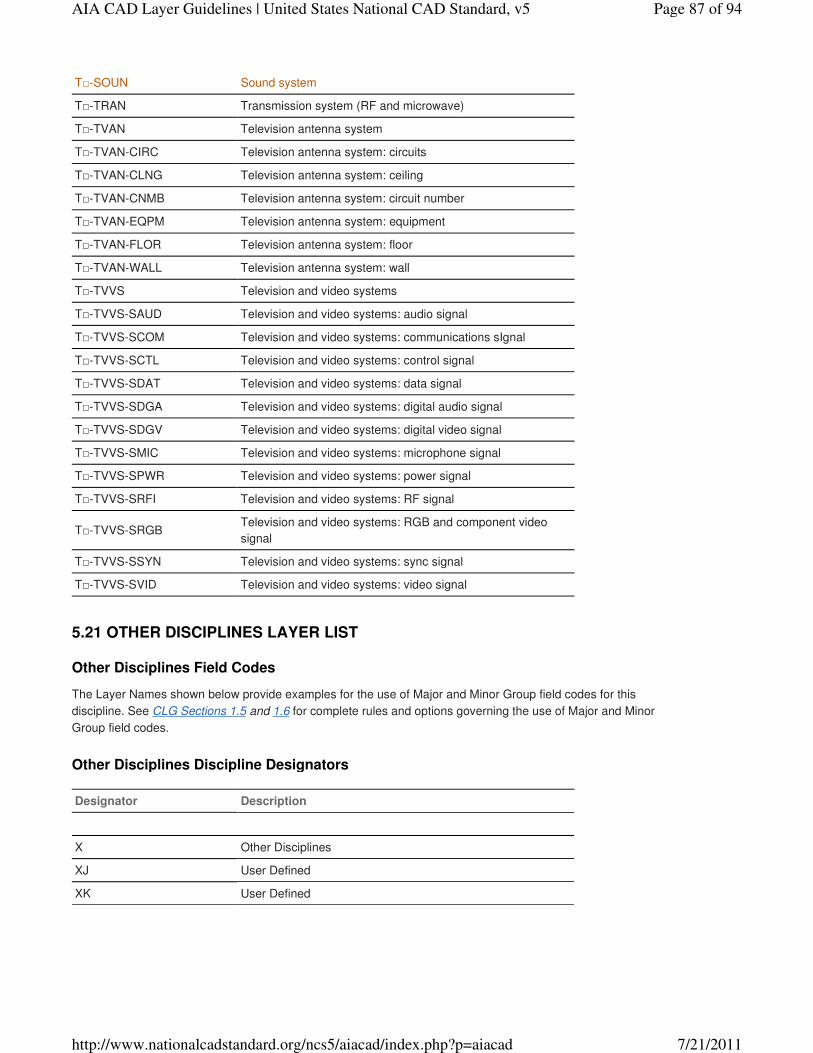
T□-SOUN Sound system
T□-TRAN Transmission system (RF and microwave)
T□-TVAN Television antenna system
T□-TVAN-CIRC Television antenna system: circuits
T□-TVAN-CLNG Television antenna system: ceiling
T□-TVAN-CNMB Television antenna system: circuit number
T□-TVAN-EQPM Television antenna system: equipment
T□-TVAN-FLOR Television antenna system: floor
T□-TVAN-WALL Television antenna system: wall
T□-TVVS Television and video systems
T□-TVVS-SAUD Television and video systems: audio signal
T□-TVVS-SCOM Television and video systems: communications sIgnal
T□-TVVS-SCTL Television and video systems: control signal
T□-TVVS-SDAT Television and video systems: data signal
T□-TVVS-SDGA Television and video systems: digital audio signal
T□-TVVS-SDGV Television and video systems: digital video signal
T□-TVVS-SMIC Television and video systems: microphone signal
T□-TVVS-SPWR Television and video systems: power signal
T□-TVVS-SRFI Television and video systems: RF signal
T□-TVVS-SRGBTelevision and video systems: RGB and component video
signal
T□-TVVS-SSYN Television and video systems: sync signal
T□-TVVS-SVID Television and video systems: video signal
Other Disciplines Field Codes
The Layer Names shown below provide examples for the use of Major and Minor Group field codes for this
discipline. See CLG Sections 1.5 and 1.6 for complete rules and options governing the use of Major and Minor
Group field codes.
Other Disciplines Discipline Designators
Designator Description
X Other Disciplines
XJ User Defined
XK User Defined
5.21 OTHER DISCIPLINES LAYER LIST
Page 87 of 94AIA CAD Layer Guidelines | United States National CAD Standard, v5
7/21/2011http://www.nationalcadstandard.org/ncs5/aiacad/index.php?p=aiacad
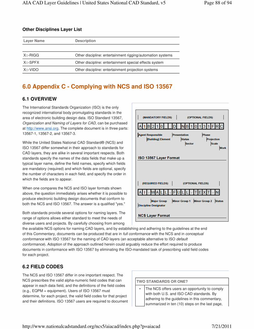
TWO STANDARDS OR ONE?
• The NCS offers users an opportunity to comply
with both U.S. and ISO CAD standards. By
adhering to the guidelines in this commentary,
summarized in ten (10) steps on the last page,
Other Disciplines Layer List
Layer Name Description
X□-RIGG Other discipline: entertainment rigging/automation systems
X□-SPFX Other discipline: entertainment special effects system
X□-VIDO Other discipline: entertainment projection systems
The International Standards Organization (ISO) is the only
recognized international body promulgating standards in the
area of electronic building design data. ISO Standard 13567,
Organization and Naming of Layers for CAD, can be purchased
at http://www.ansi.org. The complete document is in three parts:
13567-1, 13567-2, and 13567-3.
While the United States National CAD Standard® (NCS) and
ISO 13567 differ somewhat in their approach to standards for
CAD layers, they are alike in several important respects. Both
standards specify the names of the data fields that make up a
typical layer name, define the field names, specify which fields
are mandatory (required) and which fields are optional, specify
the number of characters in each field, and specify the order in
which the fields are to appear.
When one compares the NCS and ISO layer formats shown
above, the question immediately arises whether it is possible to
produce electronic building design documents that conform to
both the NCS and ISO 13567. The answer is a qualified "yes."
Both standards provide several options for naming layers. The
range of options allows either standard to meet the needs of
diverse users and projects. By carefully choosing from among
the available NCS options for naming CAD layers, and by establishing and adhering to the guidelines at the end
of this Commentary, documents can be produced that are in full conformance with the NCS and in conceptual
conformance with ISO 13567 for the naming of CAD layers (an acceptable alternative to ISO default
conformance). Adoption of the approach outlined herein could arguably reduce the effort required to produce
documents in conformance with ISO 13567 by eliminating the ISO-mandated task of prescribing valid field codes
for each project.
The NCS and ISO 13567 differ in one important respect. The
NCS prescribes the valid alpha-numeric field codes that can
appear in each data field, and the definitions of the field codes
(e.g., EQPM = equipment). Users of ISO 13567 must
determine, for each project, the valid field codes for that project
and their definitions. ISO 13567 users are required to document
6.0 Appendix C - Complying with NCS and ISO 13567
6.1 OVERVIEW
6.2 FIELD CODES
Page 88 of 94AIA CAD Layer Guidelines | United States National CAD Standard, v5
7/21/2011http://www.nationalcadstandard.org/ncs5/aiacad/index.php?p=aiacad
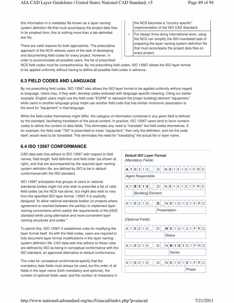
the NCS becomes a "country-specific"
implementation of the ISO CAD Standard.
• For design firms doing international work, using
the NCS can simplify the ISO-mandated task of
preparing the layer naming system definition file
that must accompany the project data files on
every project.
Default ISO Layer Format
(Mandatory Fields)
A 1 B 2 1 0 _ D N B 1 0 1 3 1 F R C
Agent Responsible
A 1 B 2 1 0 _ D N B 1 0 1 3 1 F R C
[Building] Element
A 1 B 2 1 0 _ D _ N B 1 0 1 3 1 F R C
Presentation
(Optional Fields)
A 1 B 2 1 0 _ D _ N B 1 0 1 3 1 F R C
Status
A 1 B 2 1 0 _ D _ N B 1 0 1 3 1 F R C
Sector
A 1 B 2 1 0 _ D _ N B 1 0 1 3 1 F R C
Phase
this information in a metadata file known as a layer naming
system definition file that must accompany the project data files.
In its simplest form, this is nothing more than a tab-delimited
text file.
There are valid reasons for both approaches. The prescriptive
approach of the NCS relieves users of the task of developing
and documenting field codes for every project. However, in
order to accommodate all possible users, the list of prescribed
NCS field codes must be comprehensive. By not prescribing field codes, ISO 13567 allows the ISO layer format
to be applied uniformly without having to define all possible field codes in advance.
By not prescribing field codes, ISO 13567 also allows the ISO layer format to be applied uniformly without regard
to language. Users may, if they wish, develop codes endowed with language-specific meaning. Citing our earlier
example, English users might use the field code "EQPM" to represent the [major building] element "equipment,"
while users in another language group might use another field code that has similar mnemonic association to
the word for "equipment" in that language.
While the field codes themselves might differ, the category of information contained in any given field is defined
by the standard, facilitating translation of the actual content. In practice, ISO 13567 users tend to favor numeric
codes to define the content of data fields. This eliminates any need to "translate" the field codes themselves. If,
for example, the field code "720" is prescribed to mean "equipment," then only the definition, and not the code
itself, would need to be translated. This eliminates the need for "translating" the actual file or layer name.
CAD data sets that adhere to ISO 13567 with respect to field
names, field length, field definition and field order (as shown at
right), and that are accompanied by the required layer naming
system definition file, are defined by ISO to be in default
conformance with the ISO standard.
ISO 13567 anticipates that groups of users or national
standards bodies might not only wish to prescribe a list of valid
field codes (as the NCS has done), but might also wish to vary
from the specified ISO layer format. 13567-3 is explicitly
designed "to allow national standards bodies (or projects where
agreement is reached between the parties) to implement layer
naming conventions which satisfy the requirements of the [ISO]
standard while using alternative and more convenient layer
naming structures and codes."
To permit this, ISO 13567-3 establishes rules for modifying the
layer format itself. As with the field codes, users are required to
fully document layer format modifications in the layer naming
system definition file. CAD data sets that adhere to these rules
are defined by ISO as being in conceptual conformance with the
ISO standard, an approved alternative to default conformance.
The rules for conceptual conformance specify that the
mandatory data fields must always be used, but the order of all
fields in the layer name (both mandatory and optional), the
number of optional fields used, and the number of characters in
6.3 FIELD CODES AND LANGUAGE
6.4 ISO 13567 CONFORMANCE
Page 89 of 94AIA CAD Layer Guidelines | United States National CAD Standard, v5
7/21/2011http://www.nationalcadstandard.org/ncs5/aiacad/index.php?p=aiacad

A 1 B 2 1 0 _ D _ N B 1 0 1 3 1 F R C
Projection
A 1 B 2 1 0 _ D _ N B 1 0 1 3 1 F R C
Scale
A 1 B 2 1 0 _ D _ N B 1 0 1 3 1 F R C
Work Package
Field Name Comparison Table
NCS Field Name ISO Field Name
Discipline Designator Agent Responsible
Major & Minor Groups Element
Annotation Minor Group* Presentation
Status** Status
(none) Sector
Status (Phase)** Phase
Dwg. View Minor Group*** Projection
(none) Scale
(none) Work Package
* ISO compliance requires that the last NCS Minor Group field be
reserved for annotation.
** ISO compliance requires that this field be reserved for status OR project
phase, but not both; duplicate use of the field is not permitted.
*** ISO compliance requires that Drawing View field names not appear in
the same fields as Major or Minor Group fields that define major building
elements. If both annotation and drawing view are to be included in any
layer names, one Minor Group Field must be reserved for Annotation and
the other for Drawing View.
each field can vary from the default ISO layer format.
Additionally, the names of the fields can differ from the names
specified, as long as the conceptual definition of each field
conforms to the ISO standard. All modifications to the default
layer format must be applied uniformly throughout the project.
Layer names must all be of the same length, use the same set
of mandatory and optional fields in the same order, and have
the same number of characters per field.
These rules allow data sets created in conceptual conformance
with ISO 13567 to be mapped to the ISO 13567 default layer
format. However, ISO does not require users to actually "map"
or otherwise convert the data into the default layer format.
Though the specified field names in the NCS layer format differ from the specified field names in the ISO layer
format, the definitions of the field names are conceptually the same (with one important exception, discussed in
the next paragraph below). This allows NCS-compliant data to meet the principal ISO 13567 criterion for
conceptual conformance. The Field Name Comparison Table at right highlights additional rules that must be
followed to create data that is in conformance with both the NCS and ISO 13567.
The conceptual definitions of these corresponding field names
in the NCS and ISO 13567 differ sufficiently to merit detailed
discussion. The definition for Discipline Designator is defined
in NCS as "the category of subject matter contained in the file or
layer designated." In other words, if the information contained is
"structural," the file or layer name will begin with the Discipline
Designator "S," regardless of who created the data.
ISO 13567 defines Agent Responsible as "the construction
specialist responsible for the data." Regrettably, ISO 13567
does not further define the terms "construction specialist" and
"responsible for."
"Construction specialist" could be interpreted to mean "design
professional," "design drafter," or even "skilled tradesperson or
contractor." Though the text of ISO 13567 does not define
which of these individuals is the "agent responsible," one can
reasonably infer from the sample layer naming system definition
file shown in Annex A of ISO 13567-3 that "construction
specialist" is defined as the design professional.
Identifying the design professional as the "construction
specialist" still allows considerable room for interpretation of the
definition for "agent responsible." It could be interpreted to
mean either "design professional who is professionally liable for the information by virtue of professional
licensure and role on the project," or, alternatively, "design professional who is professionally liable for the
information by virtue of having signed and sealed the document in question." An example is a lighting plan
prepared under the supervision of, and signed and sealed by, the architect. Should the field code for this
6.5 FIELD NAMES AND DEFINITIONS
6.6 DISCIPLINE DESIGNATOR" VS. "AGENT RESPONSIBLE"
6.7 "AGENT RESPONSIBLE" AND PROFESSIONAL LIABILITY
Page 90 of 94AIA CAD Layer Guidelines | United States National CAD Standard, v5
7/21/2011http://www.nationalcadstandard.org/ncs5/aiacad/index.php?p=aiacad
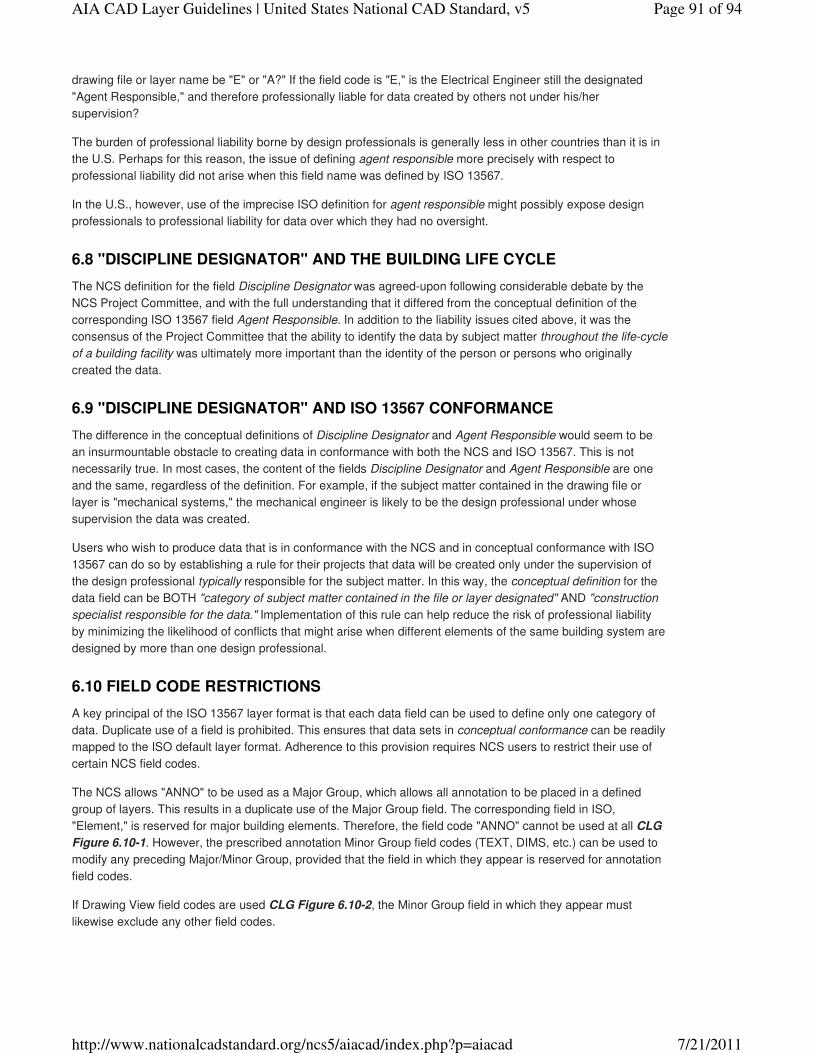
drawing file or layer name be "E" or "A?" If the field code is "E," is the Electrical Engineer still the designated
"Agent Responsible," and therefore professionally liable for data created by others not under his/her
supervision?
The burden of professional liability borne by design professionals is generally less in other countries than it is in
the U.S. Perhaps for this reason, the issue of defining agent responsible more precisely with respect to
professional liability did not arise when this field name was defined by ISO 13567.
In the U.S., however, use of the imprecise ISO definition for agent responsible might possibly expose design
professionals to professional liability for data over which they had no oversight.
The NCS definition for the field Discipline Designator was agreed-upon following considerable debate by the
NCS Project Committee, and with the full understanding that it differed from the conceptual definition of the
corresponding ISO 13567 field Agent Responsible. In addition to the liability issues cited above, it was the
consensus of the Project Committee that the ability to identify the data by subject matter throughout the life-cycle
of a building facility was ultimately more important than the identity of the person or persons who originally
created the data.
The difference in the conceptual definitions of Discipline Designator and Agent Responsible would seem to be
an insurmountable obstacle to creating data in conformance with both the NCS and ISO 13567. This is not
necessarily true. In most cases, the content of the fields Discipline Designator and Agent Responsible are one
and the same, regardless of the definition. For example, if the subject matter contained in the drawing file or
layer is "mechanical systems," the mechanical engineer is likely to be the design professional under whose
supervision the data was created.
Users who wish to produce data that is in conformance with the NCS and in conceptual conformance with ISO
13567 can do so by establishing a rule for their projects that data will be created only under the supervision of
the design professional typically responsible for the subject matter. In this way, the conceptual definition for the
data field can be BOTH "category of subject matter contained in the file or layer designated" AND "construction
specialist responsible for the data." Implementation of this rule can help reduce the risk of professional liability
by minimizing the likelihood of conflicts that might arise when different elements of the same building system are
designed by more than one design professional.
A key principal of the ISO 13567 layer format is that each data field can be used to define only one category of
data. Duplicate use of a field is prohibited. This ensures that data sets in conceptual conformance can be readily
mapped to the ISO default layer format. Adherence to this provision requires NCS users to restrict their use of
certain NCS field codes.
The NCS allows "ANNO" to be used as a Major Group, which allows all annotation to be placed in a defined
group of layers. This results in a duplicate use of the Major Group field. The corresponding field in ISO,
"Element," is reserved for major building elements. Therefore, the field code "ANNO" cannot be used at all CLG
Figure 6.10-1. However, the prescribed annotation Minor Group field codes (TEXT, DIMS, etc.) can be used to
modify any preceding Major/Minor Group, provided that the field in which they appear is reserved for annotation
field codes.
If Drawing View field codes are used CLG Figure 6.10-2, the Minor Group field in which they appear must
likewise exclude any other field codes.
6.8 "DISCIPLINE DESIGNATOR" AND THE BUILDING LIFE CYCLE
6.9 "DISCIPLINE DESIGNATOR" AND ISO 13567 CONFORMANCE
6.10 FIELD CODE RESTRICTIONS
Page 91 of 94AIA CAD Layer Guidelines | United States National CAD Standard, v5
7/21/2011http://www.nationalcadstandard.org/ncs5/aiacad/index.php?p=aiacad
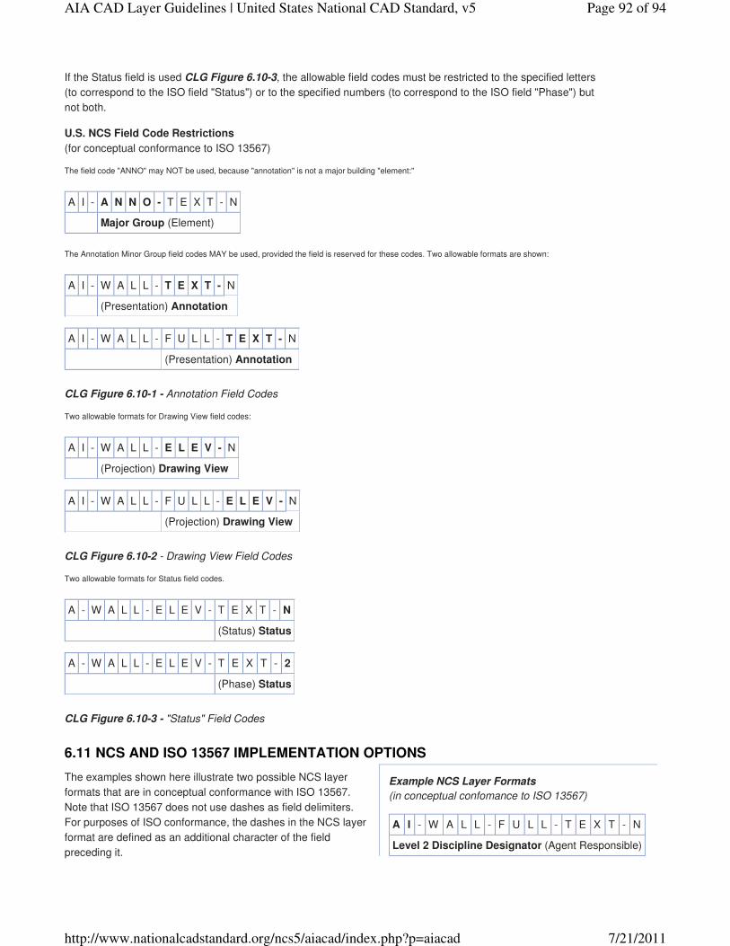
Example NCS Layer Formats
(in conceptual confomance to ISO 13567)
A I - W A L L - F U L L - T E X T - N
Level 2 Discipline Designator (Agent Responsible)
If the Status field is used CLG Figure 6.10-3, the allowable field codes must be restricted to the specified letters
(to correspond to the ISO field "Status") or to the specified numbers (to correspond to the ISO field "Phase") but
not both.
U.S. NCS Field Code Restrictions
(for conceptual conformance to ISO 13567)
The field code "ANNO" may NOT be used, because "annotation" is not a major building "element:"
A I - A N N O - T E X T - N
Major Group (Element)
The Annotation Minor Group field codes MAY be used, provided the field is reserved for these codes. Two allowable formats are shown:
A I - W A L L - T E X T - N
(Presentation) Annotation
A I - W A L L - F U L L - T E X T - N
(Presentation) Annotation
CLG Figure 6.10-1 - Annotation Field Codes
Two allowable formats for Drawing View field codes:
A I - W A L L - E L E V - N
(Projection) Drawing View
A I - W A L L - F U L L - E L E V - N
(Projection) Drawing View
CLG Figure 6.10-2 - Drawing View Field Codes
Two allowable formats for Status field codes.
A - W A L L - E L E V - T E X T - N
(Status) Status
A - W A L L - E L E V - T E X T - 2
(Phase) Status
CLG Figure 6.10-3 - "Status" Field Codes
The examples shown here illustrate two possible NCS layer
formats that are in conceptual conformance with ISO 13567.
Note that ISO 13567 does not use dashes as field delimiters.
For purposes of ISO conformance, the dashes in the NCS layer
format are defined as an additional character of the field
preceding it.
6.11 NCS AND ISO 13567 IMPLEMENTATION OPTIONS
Page 92 of 94AIA CAD Layer Guidelines | United States National CAD Standard, v5
7/21/2011http://www.nationalcadstandard.org/ncs5/aiacad/index.php?p=aiacad

A I - W A L L - F U L L - T E X T - N
Major, Minor Group (Element)
A I - W A L L - F U L L - T E X T - N
(Presentation) Annotation
A I - W A L L - F U L L - T E X T - N
(Status) Status
CLG Figure 6.11-1
A - W A L L - E L E V - T E X T - 2
Level 1 Discipline Designator (Agent Responsible)
A - W A L L - E L E V - T E X T - 2
Major Group (Element)
A - W A L L - E L E V - T E X T - 2
Drawing View (Projection)
A - W A L L - E L E V - T E X T - 2
(Presentation) Annotation
A - W A L L - E L E V - T E X T - 2
(Phase) Status
CLG Figure 6.11-2
CLG Figure 6.11-1 shows the optional two-character NCS
Level 2 Discipline Designator; together with the dash that
follows it, this field is defined as three (3) characters in length. A
Major and one Minor Group are defined as corresponding to the
ISO field [Building] "Element." The field is ten (10) characters in
length. The second Minor Group is reserved for Annotation field
codes, corresponds to the ISO field "Presentation," and is five
(5) characters in length. The final field is Status, which
corresponds to the ISO field of the same name, and is one (1)
character in length.
CLG Figure 6.11-2 shows the NCS required Level 1 Discipline
Designator only, and is defined as two (2) characters in length.
The Major Group is defined as corresponding to the ISO field
[Building] "Element," and is five (5) characters in length. The
first Minor Group is reserved for Drawing View field codes,
corresponds to the ISO field "Projection," and is five (5)
characters in length. The second Minor Group is reserved for
Annotation field codes, corresponds to the ISO field
"Presentation," and is five (5) characters in length. The final field
is reserved for Phase field codes, corresponds to the ISO field
"Phase," and is one (1) character in length.
Note that for ISO conformance, the total length of the layer
name must be the same for all layers on a given project. Layer
names that do not require a certain field, such as "Annotation,"
must use placeholders (usually dashes or underscores) to
maintain the length of the layer name and the relative position of
the fields.
While the ISO 13567 rules for conceptual conformance allow
the fields to appear in any order, this is not permitted by the
NCS. The fields must be in the order of Discipline Designator,
Major Group, Minor Group 1, Minor Group 2, Status. If a Minor Group field is used to modify the "building
element" shown in the Major Group, that Minor Group must appear immediately following the Major Group.
The information in this Commentary is summarized in the following steps for preparing documents with layer
names in conformance with the NCS and in conceptual conformance with ISO 13567. While these guidelines
are intended to aid NCS users, adherence to these rules in some form would be required by ISO 13567 whether
or not the NCS layer format were used.
Require that all documents be prepared only under the supervision of the design professional typically
responsible for the subject matter contained in the documents.
1.
Do not use the field code "ANNO" in any layer name.2.
Determine whether the Discipline Designator will be one character (Level 1) or two characters (Level 2) in
length.
3.
Determine whether the "building element" will consist of a Major Group only, or of a Major Group and one
Minor Group.
4.
Determine whether a Minor Group is to be reserved for Drawing View field codes, and fix its position in the
sequence of fields.
5.
Determine whether a Minor Group is to be reserved for Annotation field codes, and fix its position in the
sequence of fields.
6.
6.12 NCS AND ISO 13567 IMPLEMENTATION GUIDELINES
Page 93 of 94AIA CAD Layer Guidelines | United States National CAD Standard, v5
7/21/2011http://www.nationalcadstandard.org/ncs5/aiacad/index.php?p=aiacad
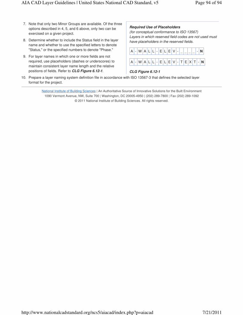
Required Use of Placeholders
(for conceptual conformance to ISO 13567)
Layers in which reserved field codes are not used must
have placeholders in the reserved fields.
A - W A L L - E L E V - _ _ _ _ - N
A - W A L L - E L E V - T E X T - N
CLG Figure 6.12-1
Note that only two Minor Groups are available. Of the three
options described in 4, 5, and 6 above, only two can be
exercised on a given project.
7.
Determine whether to include the Status field in the layer
name and whether to use the specified letters to denote
"Status," or the specified numbers to denote "Phase."
8.
For layer names in which one or more fields are not
required, use placeholders (dashes or underscores) to
maintain consistent layer name length and the relative
positions of fields. Refer to CLG Figure 6.12-1.
9.
Prepare a layer naming system definition file in accordance with ISO 13567-3 that defines the selected layer
format for the project.
10.
National Institute of Building Sciences | An Authoritative Source of Innovative Solutions for the Built Environment
1090 Vermont Avenue, NW, Suite 700 | Washington, DC 20005-4950 | (202) 289-7800 | Fax (202) 289-1092
© 2011 National Institute of Building Sciences. All rights reserved.
Page 94 of 94AIA CAD Layer Guidelines | United States National CAD Standard, v5
7/21/2011http://www.nationalcadstandard.org/ncs5/aiacad/index.php?p=aiacad