Embed Size (px)
Citation preview
AAIIAAAA 9966--22775511
TITANIUM-LINED, CARBON COMPOSITE OVERWRAPPED PRESSURE VESSEL
Gary Kawahara Pressure Systems, Inc. Commerce, Ca. 90040
Stephen F. McCleskey
Kaiser Compositek Corporation Brea, Ca. 92621 Member AIAA
ABSTRACT The design, manufacture, and test of a high performance composite overwrapped pressure vessel (COPV) utilizing a titanium liner is described. The vessel is unique in that the liner and end fittings are fabricated from commercially pure (cp) titanium with the attendant advantages of high corrosion and oxidation resistance, good low cycle fatigue characteristics (for pressure cycling) and good high cycle fatigue characteristics (for environmental testing). Liner manufacturing costs are reduced relative to other titanium alloys because cp titanium sheet is readily formed at room temperature and is easily weldable. The vessel is overwrapped with high performance carbon fiber impregnated with an epoxy resin. The tank was designed as a helium pressurant supply tank for a commercial communications satellite and has demonstrated PbV/W ratio of approximately 1.5 x 106 inches. Topics covered include a brief overview of COPV technology, trade studies, tank design and analysis, performance summary, fabrication, qualification, and test results.
INTRODUCTION Pressurized systems are required on many spacecraft in order to operate fluid management and propulsion systems. High performance composite overwrapped pressure vessels (COPVs) have been utilized in the aerospace and automotive industries for many years, providing an inherently safe, lightweight and cost effective storage source for pressurized fluids.
In a typical COPV design, an ultra-thin metallic liner is overwrapped with a reinforcing fiber and epoxy matrix. For typical operating pressures, this combination offers tremendous weight savings over equivalent monolithic metal vessels.
Low cycle fatigue characteristics are important for liner material selection because the liner plastically yields during each pressure cycle. Liner material ultimate strength and high cycle fatigue characteristics are
equally important because the port openings and attachments are subjected to the full pressure load and external acceleration loads. Typical COPV’s utilize 5086 and 6061-T6 aluminum as liner materials of choice. Recent research at Pressure Systems, Inc. (PSI) and Kaiser Compositek Corp. (KCC) has shown that commercially pure (cp) titanium specifically CP-3* for the liner and CP-70† for the port openings and attachments can serve as an excellent liner, eliminating many of the manufacturing and process problems associated with aluminum while improving the strength and fatigue properties of the liner.
This paper describes the design, manufacture, and test of a new COPV utilizing a cp titanium liner, Torayca T1000‡ carbon fiber, Epon 826§ epoxy resin, and a toughened epoxy film adhesive. This vessel is unique in its utilization of a titanium liner, with the attendant advantages of good low cycle fatigue characteristics (for pressure cycling), good high cycle fatigue characteristics (for vibration loading of end attachments), and high corrosion and oxidation resistance.
Figure 1 shows the basic configuration of the pressure vessel. The tank is intended to store approximately 6 lbs of helium at a maximum expected operating pressure (MEOP) of 4500 psi at 140°F. Proof pressure is 5625 psi and minimum burst pressure is 6750 psi.
** CCPP--33 TTii ppeerr MMIILL--TT--99004466JJ -- 4400 kkssii yyiieelldd ssttrreennggtthh †† CCPP--7700 TTii ppeerr MMIILL--TT--99004477GG -- 7700 kkssii yyiieelldd ssttrreennggtthh ‡ T1000 carbon fiber is a product of Toray Industries, Inc., Tokyo, Japan.
CCooppyyrriigghhtt 11999966 bbyy PPrreessssuurree SSyysstteemmss,, IInncc.. && KKaaiisseerr CCoommppoossiitteekk CCoorrpp.. PPuubblliisshheedd bbyy AAmmeerriiccaann IInnssttiittuuttee ooff AAeerroonnaauuttiiccss && AAssttrroonnaauuttiiccss wwiitthh ppeerrmmiissssiioonn..
PPaaggee 33
§ Epon 826 resin is a product of Shell Oil Co., Houston, Texas.
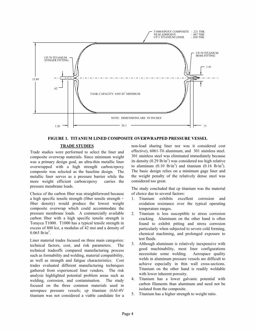
T1000/EPOXY COMPOSITE - .221 THKFILM ADHESIVE - .007 THKCP-3 TITANIUM LINER - .020 THK
CP-70 TITANIUMBOSS FITTINGCP-70 TITANIUM
STINGER FITTING
15.89
26.1 .711.26
.62
1.41
NOTE: DIMENSIONS ARE IN INCHES
TANK CAPACITY: 4105 IN3 MINIMUM
FFIIGGUURREE 11.. TTIITTAANNIIUUMM LLIINNEEDD CCOOMMPPOOSSIITTEE OOVVEERRWWRRAAPPPPEEDD PPRREESSSSUURREE VVEESSSSEELL
TRADE STUDIES Trade studies were performed to select the liner and composite overwrap materials. Since minimum weight was a primary design goal, an ultra-thin metallic liner overwrapped with a high strength carbon/epoxy composite was selected as the baseline design. The metallic liner serves as a pressure barrier while the more weight efficient carbon/epoxy carries the pressure membrane loads.
Choice of the carbon fiber was straightforward because a high specific tensile strength (fiber tensile strength ÷ fiber density) would produce the lowest weight composite overwrap which could accommodate the pressure membrane loads. A commercially available carbon fiber with a high specific tensile strength is Torayca T1000. T1000 has a typical tensile strength in excess of 800 ksi, a modulus of 42 msi and a density of 0.065 lb/in3.
Liner material trades focused on three main categories: technical factors, cost, and risk parameters. The technical tradeoffs compared manufacturing process such as formability and welding, material compatibility, as well as strength and fatigue characteristics. Cost trades evaluated different manufacturing techniques gathered from experienced liner vendors. The risk analysis highlighted potential problem areas such as welding, corrosion, and contamination. The study focused on the three common materials used in aerospace pressure vessels; cp titanium (6Al-4V titanium was not considered a viable candidate for a
non-load sharing liner nor was it considered cost effective), 6061-T6 aluminum, and 301 stainless steel. 301 stainless steel was eliminated immediately because its density (0.29 lb/in3) was considered too high relative to aluminum (0.10 lb/in3) and titanium (0.16 lb/in3). The basic design relies on a minimum gage liner and the weight penalty of the relatively dense steel was considered too great.
The study concluded that cp titanium was the material of choice due to several factors: 1. Titanium exhibits excellent corrosion and
oxidation resistance over the typical operating temperature ranges.
2. Titanium is less susceptible to stress corrosion cracking. Aluminum on the other hand is often found to exhibit pitting and stress corrosion particularly when subjected to severe cold forming, chemical machining, and prolonged exposure to test fluids.
3. Although aluminum is relatively inexpensive with good machinability, most liner configurations necessitate some welding. Aerospace quality welds in aluminum pressure vessels are difficult to achieve especially in thin wall cross-sections. Titanium on the other hand is readily weldable with lower inherent porosity.
4. Titanium has a lower galvanic potential with carbon filaments than aluminum and need not be isolated from the composite.
5. Titanium has a higher strength to weight ratio.
PPaaggee 44
6. CP titanium is readily cold formable and can be economically manufactured into a very uniform thin wall liner.
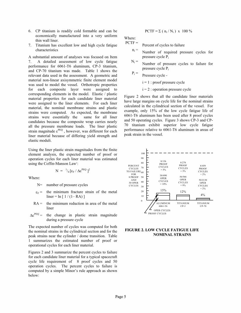
PCTF = Σ ( ni / Ni ) x 100 %
Where: PCTF = Percent of cycles to failure
ni = Number of required pressure cycles for pressure cycle Pi
Ni = Number of pressure cycles to failure for pressure cycle Pi
Pi = Pressure cycle -
i = 1 : proof pressure cycle
i = 2 : operation pressure cycle
7. Titanium has excellent low and high cycle fatigue characteristics
A substantial amount of analyses was focused on Item 7. A detailed assessment of low cycle fatigue performance for 6061-T6 aluminum, CP-3 titanium, and CP-70 titanium was made. Table 1 shows the relevant data used in the assessment. A geometric and material non-linear axisymmetric finite element model was used to model the vessel. Orthotropic properties for each composite layer were assigned to corresponding elements in the model. Elastic / plastic material properties for each candidate liner material were assigned to the liner elements. For each liner material, the nominal membrane strains and plastic strains were computed. As expected, the membrane strains were essentially the same for all liner candidates because the composite wrap carries nearly all the pressure membrane loads. The liner plastic strain magnitude εPEQ , however, was different for each liner material becuase of differing yield strength and elastic moduli.
Figure 2 shows that all the candidate liner materials have large margins on cycle life for the nominal strains calculated in the cylindrical section of the vessel. For example, only 15% of the low cycle fatigue life of 6061-T6 aluminum has been used after 8 proof cycles and 50 operating cycles. Figure 3 shows CP-3 and CP-70 titanium exhibit superior low cycle fatigue performance relative to 6061-T6 aluminum in areas of peak strain in the vessel.
Using the liner plastic strain magnitudes from the finite element analysis, the expected number of proof or operation cycles for each liner material was estimated using the Coffin-Manson Law1:
PERCENTCYCLES
TO FAILUREFOR
8 PROOFAND
50 OPERCYCLES
0
10
20
30
40
50
60
70
80
90
100
PROOF CYCLESOPER CYCLES
8/459PROOF
CYCLES= 2%
50/2130OPER
CYCLES= 2%
4%
8/278PROOF
CYCLES= 3%
50/588OPER
CYCLES= 9%
12%
8/156PROOF
CYCLES= 5%
50/490OPER
CYCLES= 10%
15%
TITANIUMCP-70
TITANIUMCP-3
ALUMINUM6061-T6
FFIIGGUURREE 22.. LLOOWW CCYYCCLLEE FFAATTIIGGUUEE LLIIFFEE NNOOMMIINNAALL SSTTRRAAIINNSS
N = 1/4 [εF / ∆εPEQ ]2
Where:
N= number of pressure cycles
εF = the minimum fracture strain of the metal liner = ln [ 1 / (1– RA) ]
RA = the minimum reduction in area of the metal liner
∆εPEQ = the change in plastic strain magnitude during a pressure cycle
The expected number of cycles was computed for both the nominal strains in the cylindrical section and for the peak strains near the cylinder / dome transition. Table 1 summarizes the estimated number of proof or operational cycles for each liner material.
Figures 2 and 3 summarize the percent cycles to failure for each candidate liner material for a typical spacecraft cycle life requirement of 8 proof cycles and 50 operation cycles. The percent cycles to failure is computed by a simple Minor’s rule approach as shown below:
PPaaggee 55
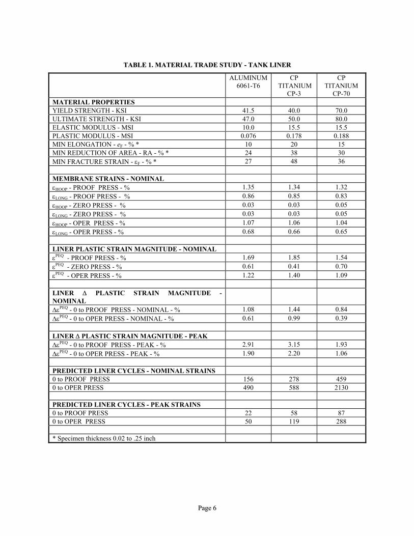
TTAABBLLEE 11.. MMAATTEERRIIAALL TTRRAADDEE SSTTUUDDYY -- TTAANNKK LLIINNEERR
ALUMINUM 6061-T6
CP TITANIUM
CP-3
CP TITANIUM
CP-70 MATERIAL PROPERTIES YIELD STRENGTH - KSI 41.5 40.0 70.0 ULTIMATE STRENGTH - KSI 47.0 50.0 80.0 ELASTIC MODULUS - MSI 10.0 15.5 15.5 PLASTIC MODULUS - MSI 0.076 0.178 0.188 MIN ELONGATION - eF - % * 10 20 15 MIN REDUCTION OF AREA - RA - % * 24 38 30 MIN FRACTURE STRAIN - εF - % * 27 48 36 MEMBRANE STRAINS - NOMINAL εHOOP - PROOF PRESS - % 1.35 1.34 1.32 εLONG - PROOF PRESS - % 0.86 0.85 0.83 εHOOP - ZERO PRESS - % 0.03 0.03 0.05 εLONG - ZERO PRESS - % 0.03 0.03 0.05 εHOOP - OPER PRESS - % 1.07 1.06 1.04 εLONG - OPER PRESS - % 0.68 0.66 0.65 LINER PLASTIC STRAIN MAGNITUDE - NOMINAL εPEQ - PROOF PRESS - % 1.69 1.85 1.54 εPEQ - ZERO PRESS - % 0.61 0.41 0.70 εPEQ - OPER PRESS - % 1.22 1.40 1.09 LINER ∆ PLASTIC STRAIN MAGNITUDE - NOMINAL
∆εPEQ - 0 to PROOF PRESS - NOMINAL - % 1.08 1.44 0.84 ∆εPEQ - 0 to OPER PRESS - NOMINAL - % 0.61 0.99 0.39 LINER ∆ PLASTIC STRAIN MAGNITUDE - PEAK ∆εPEQ - 0 to PROOF PRESS - PEAK - % 2.91 3.15 1.93 ∆εPEQ - 0 to OPER PRESS - PEAK - % 1.90 2.20 1.06 PREDICTED LINER CYCLES - NOMINAL STRAINS 0 to PROOF PRESS 156 278 459 0 to OPER PRESS 490 588 2130 PREDICTED LINER CYCLES - PEAK STRAINS 0 to PROOF PRESS 22 58 87 0 to OPER PRESS 50 119 288 * Specimen thickness 0.02 to .25 inch
PPaaggee 66
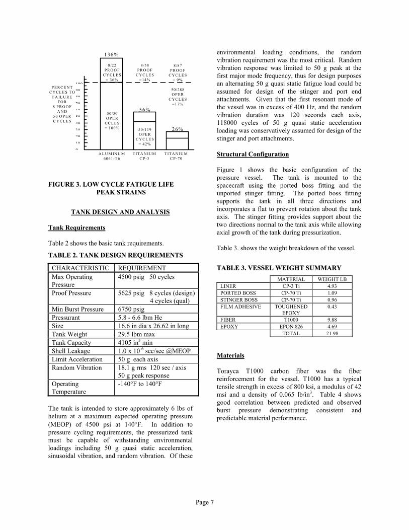
FFIIGGUURREE 33.. LLOOWW CCYYCCLLEE FFAATTIIGGUUEE LLIIFFEE PPEEAAKK SSTTRRAAIINNSS
TANK DESIGN AND ANALYSIS
Tank Requirements Table 2 shows the basic tank requirements.
TTAABBLLEE 22.. TTAANNKK DDEESSIIGGNN RREEQQUUIIRREEMMEENNTTSS
CHARACTERISTIC REQUIREMENT Max Operating Pressure
4500 psig 50 cycles
Proof Pressure 5625 psig 8 cycles (design) 4 cycles (qual)
Min Burst Pressure 6750 psig Pressurant 5.8 - 6.6 lbm He Size 16.6 in dia x 26.62 in long Tank Weight 29.5 lbm max Tank Capacity 4105 in3 min Shell Leakage 1.0 x 10⁻⁶ scc/sec @MEOP Limit Acceleration 50 g each axis Random Vibration 18.1 g rms 120 sec / axis
50 g peak response Operating Temperature
-140°F to 140°F
The tank is intended to store approximately 6 lbs of helium at a maximum expected operating pressure (MEOP) of 4500 psi at 140°F. In addition to pressure cycling requirements, the pressurized tank must be capable of withstanding environmental loadings including 50 g quasi static acceleration, sinusoidal vibration, and random vibration. Of these
environmental loading conditions, the random vibration requirement was the most critical. Random vibration response was limited to 50 g peak at the first major mode frequency, thus for design purposes an alternating 50 g quasi static fatigue load could be assumed for design of the stinger and port end attachments. Given that the first resonant mode of the vessel was in excess of 400 Hz, and the random vibration duration was 120 seconds each axis, 118000 cycles of 50 g quasi static acceleration loading was conservatively assumed for design of the stinger and port attachments.
100
9080
7060
50
403020
10
0
PE RCE N TCY CL E S T O
FA IL U REFO R
8 PRO O FA N D
50 O PE RCY CL E S
T IT A N IU MCP-70
T IT A N IU MCP-3
A L U M IN U M6061-T 6
8/22PRO O F
CY CL E S= 36%
50/50O PE R
CCL E S= 100%
8/58PRO O F
CY CL E S=14%
56%
50/119O PE R
CY CL E S= 42%
8/87PRO O F
CY CL E S= 9%
50/288O PE R
CY CL E S=17%
26%
136%
Structural Configuration Figure 1 shows the basic configuration of the pressure vessel. The tank is mounted to the spacecraft using the ported boss fitting and the unported stinger fitting. The ported boss fitting supports the tank in all three directions and incorporates a flat to prevent rotation about the tank axis. The stinger fitting provides support about the two directions normal to the tank axis while allowing axial growth of the tank during pressurization. Table 3. shows the weight breakdown of the vessel.
TTAABBLLEE 33.. VVEESSSSEELL WWEEIIGGHHTT SSUUMMMMAARRYY
MATERIAL WEIGHT LB LINER CP-3 Ti 4.93 PORTED BOSS CP-70 Ti 1.09 STINGER BOSS CP-70 Ti 0.96 FILM ADHESIVE TOUGHENED
EPOXY 0.43
FIBER T1000 9.88 EPOXY EPON 826 4.69 TOTAL 21.98
Materials Torayca T1000 carbon fiber was the fiber reinforcement for the vessel. T1000 has a typical tensile strength in excess of 800 ksi, a modulus of 42 msi and a density of 0.065 lb/in3. Table 4 shows good correlation between predicted and observed burst pressure demonstrating consistent and predictable material performance.
PPaaggee 77
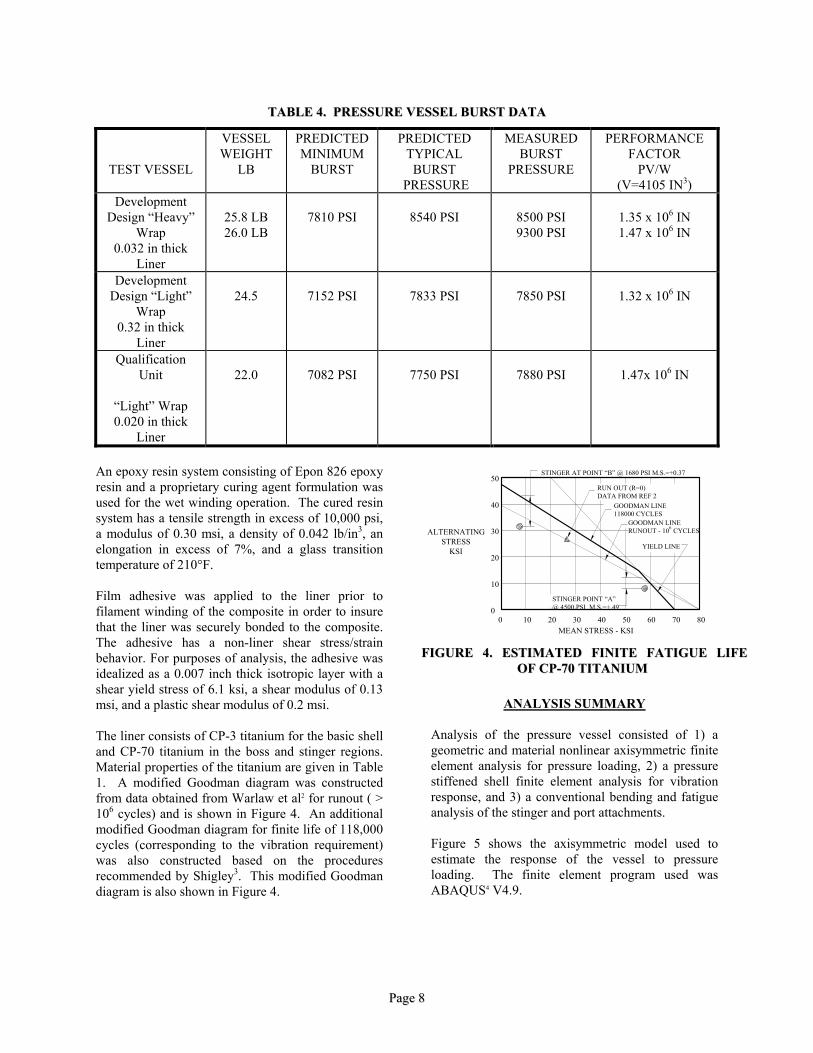
TTAABBLLEE 44.. PPRREESSSSUURREE VVEESSSSEELL BBUURRSSTT DDAATTAA
TEST VESSEL
VESSEL WEIGHT
LB
PREDICTED MINIMUM
BURST
PREDICTED TYPICAL
BURST PRESSURE
MEASURED BURST
PRESSURE
PERFORMANCE FACTOR
PV/W (V=4105 IN3)
Development Design “Heavy”
Wrap 0.032 in thick
Liner
25.8 LB 26.0 LB
7810 PSI
8540 PSI
8500 PSI 9300 PSI
1.35 x 10⁶ IN 1.47 x 10⁶ IN
Development Design “Light”
Wrap 0.32 in thick
Liner
24.5
7152 PSI
7833 PSI
7850 PSI
1.32 x 10⁶ IN
Qualification Unit
“Light” Wrap 0.020 in thick
Liner
22.0
7082 PSI
7750 PSI
7880 PSI
1.47x 10⁶ IN
An epoxy resin system consisting of Epon 826 epoxy resin and a proprietary curing agent formulation was used for the wet winding operation. The cured resin system has a tensile strength in excess of 10,000 psi, a modulus of 0.30 msi, a density of 0.042 lb/in3, an elongation in excess of 7%, and a glass transition temperature of 210°F.
50
0 20 30 40 70 80MEAN STRESS - KSI
GOODMAN LINE118000 CYCLES
GOODMAN LINERUNOUT - 106 CYCLES
10
YIELD LINE
0
10
20
30
40
50 60
STINGER AT POINT “B” @ 1680 PSI M.S.=+0.37
RUN OUT (R=0)DATA FROM REF 2
STINGER POINT “A”@ 4500 PSI M.S.=+.49
ALTERNATINGSTRESS
KSI
FFIIGGUURREE 44.. EESSTTIIMMAATTEEDD FFIINNIITTEE FFAATTIIGGUUEE LLIIFFEE OOFF CCPP--7700 TTIITTAANNIIUUMM
Film adhesive was applied to the liner prior to filament winding of the composite in order to insure that the liner was securely bonded to the composite. The adhesive has a non-liner shear stress/strain behavior. For purposes of analysis, the adhesive was idealized as a 0.007 inch thick isotropic layer with a shear yield stress of 6.1 ksi, a shear modulus of 0.13 msi, and a plastic shear modulus of 0.2 msi. ANALYSIS SUMMARY
Analysis of the pressure vessel consisted of 1) a geometric and material nonlinear axisymmetric finite element analysis for pressure loading, 2) a pressure stiffened shell finite element analysis for vibration response, and 3) a conventional bending and fatigue analysis of the stinger and port attachments.
The liner consists of CP-3 titanium for the basic shell and CP-70 titanium in the boss and stinger regions. Material properties of the titanium are given in Table 1. A modified Goodman diagram was constructed from data obtained from Warlaw et al2 for runout ( > 106 cycles) and is shown in Figure 4. An additional modified Goodman diagram for finite life of 118,000 cycles (corresponding to the vibration requirement) was also constructed based on the procedures recommended by Shigley3. This modified Goodman diagram is also shown in Figure 4.
Figure 5 shows the axisymmetric model used to estimate the response of the vessel to pressure loading. The finite element program used was ABAQUS4 V4.9.
PPaaggee 88
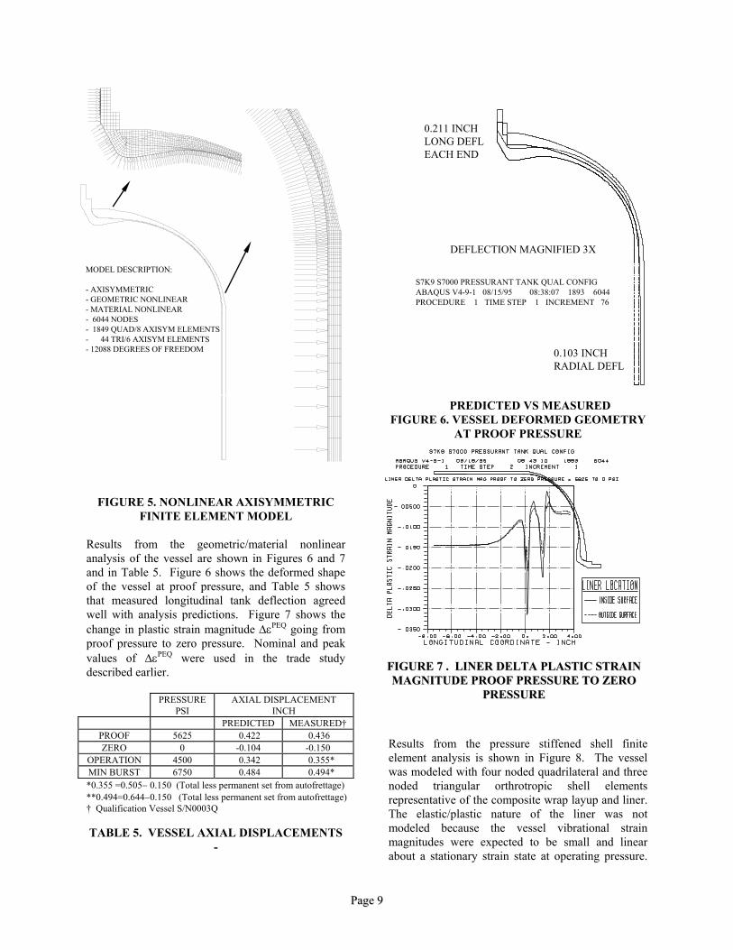
MODEL DESCRIPTION:
- AXISYMMETRIC- GEOMETRIC NONLINEAR- MATERIAL NONLINEAR- 6044 NODES- 1849 QUAD/8 AXISYM ELEMENTS- 44 TRI/6 AXISYM ELEMENTS- 12088 DEGREES OF FREEDOM
DEFLECTION MAGNIFIED 3X
0.211 INCHLONG DEFLEACH END
0.103 INCHRADIAL DEFL
S7K9 S7000 PRESSURANT TANK QUAL CONFIGABAQUS V4-9-1 08/15/95 08:38:07 1893 6044PROCEDURE 1 TIME STEP 1 INCREMENT 76
PREDICTED VS MEASURED
FIGURE 6. VESSEL DEFORMED GEOMETRY AT PROOF PRESSURE
FIGURE 5. NONLINEAR AXISYMMETRIC FINITE ELEMENT MODEL
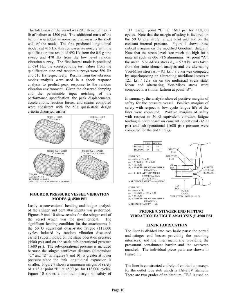
Results from the geometric/material nonlinear analysis of the vessel are shown in Figures 6 and 7 and in Table 5. Figure 6 shows the deformed shape of the vessel at proof pressure, and Table 5 shows that measured longitudinal tank deflection agreed well with analysis predictions. Figure 7 shows the change in plastic strain magnitude ∆εPEQ going from proof pressure to zero pressure. Nominal and peak values of ∆εPEQ were used in the trade study described earlier.
PRESSURE PSI
AXIAL DISPLACEMENT INCH
PREDICTED MEASURED† PROOF 5625 0.422 0.436 ZERO 0 -0.104 -0.150
OPERATION 4500 0.342 0.355* MIN BURST 6750 0.484 0.494*
FFIIGGUURREE 77 .. LLIINNEERR DDEELLTTAA PPLLAASSTTIICC SSTTRRAAIINN MMAAGGNNIITTUUDDEE PPRROOOOFF PPRREESSSSUURREE TTOO ZZEERROO
PPRREESSSSUURREE
Results from the pressure stiffened shell finite element analysis is shown in Figure 8. The vessel was modeled with four noded quadrilateral and three noded triangular orthrotropic shell elements representative of the composite wrap layup and liner. The elastic/plastic nature of the liner was not modeled because the vessel vibrational strain magnitudes were expected to be small and linear about a stationary strain state at operating pressure.
*0.355 =0.505− 0.150 (Total less permanent set from autofrettage) **0.494=0.644−0.150 (Total less permanent set from autofrettage) † Qualification Vessel S/N0003Q
TABLE 5. VESSEL AXIAL DISPLACEMENTS
-
PPaaggee 99
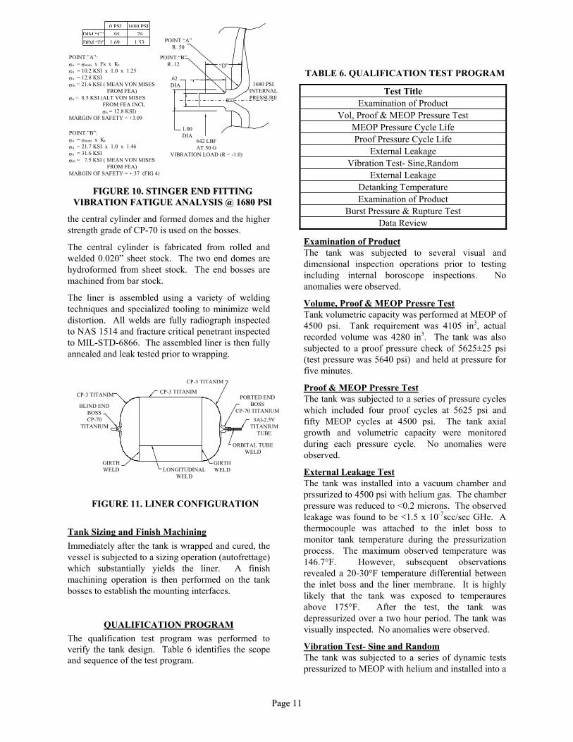
The total mass of the vessel was 29.7 lb including 6.7 lb of helium at 4500 psi. The additional mass of the helium was added as non-structural mass to the shell wall of the model. The first predicted longitudinal mode is at 415 Hz, this compares reasonably with the qualification test result of 492 Hz from the 0.5 g sine sweep and 470 Hz from the low level random vibration survey. The first lateral mode is predicted at 684 Hz; the corresponding test values from the qualification sine and random surveys were 560 Hz and 510 Hz respectively. Results from the vibration modes analysis were used in a shock response analysis to predict peak response to the random vibration environment. Given the observed damping and the permissible input notching of the performance specification, the peak displacements, accelerations, reaction forces, and strains computed were consistent with the 50g quasi-static design criteria discussed earlier.
MODE 1: 160 HZ1ST TORSION
MODE 2: 415 HZ1ST AXIAL
MODES 3 & 4: 688 HZ1ST LATERAL
MODES 5 & 6: 1170 HZ1ST LATERAL/ROTATIONAL
VIB_S7KABAQUS V4-9-1PRESSURE = 4500 PSITOTAL MASS = 29.7 LBM (INCL 6.7 LBM He)
FFIIGGUURREE 88.. PPRREESSSSUURREE VVEESSSSEELL VVIIBBRRAATTIIOONN MMOODDEESS @@ 44550000 PPSSII
Lastly, a conventional bending and fatigue analysis of the stinger and port attachments was performed. Figures 9 and 10 show results for the stinger end of the vessel which was the most critical. The significant loading condition for the attachments is the 50 G equivalent quasi-static fatigue (118,000 cycles induced by random vibration discussed earlier) superimposed on the static operation pressure (4500 psi) and on the static sub-operational pressure (1680 psi). The sub-operational pressure is included because the stinger cantilever distance (dimensions “C” and “D” in Figures 9 and 10) is greater at lower pressure since the tank longitudinal expansion is smaller. Figure 9 shows a minimum margin of safety of +.48 at point “B” at 4500 psi for 118,000 cycles. Figure 10 shows a minimum margin of safety of
+.37 margin point “B” at 1680 psi for 118,000 cycles. Note that the margin of safety is factored on the 50 G alternating fatigue load and not on the constant internal pressure. Figure 4 shows these critical margins on the modified Goodman diagram. Note that the stress levels are much too high for a material such as 6061-T6 aluminum. At point “A”, the mean Von-Mises stress σm = 57.9 ksi was taken from the finite element analysis and the alternating Von-Mises stress σa = 8.1 ksi / 8.5 ksi was computed by superimposing an alternating meridional stress = 12.1 ksi / 12.8 ksi on the multiaxial stress state. Mean and alternating Von-Mises stress were computed in a similar fashion at point “B”. In summary, the analysis showed positive margins of safety for the pressure vessel. Positive margins of safety with respect to low cycle fatigue life of the liner were computed. Positive margins of safety with respect to 50 G equivalent vibration fatigue loading superimposed on constant operational (4500 psi) and sub-operational (1680 psi) pressure were computed for the end fittings.
4500 PSIINTERNALPRESSURE
“C”
“D”
.62DIA
1.00DIA
POINT “A”R .50
POINT “B”R .12
1.69 1.26.95 .52
0 PSI 4500 PSIDIM “C”DIM “D”
POINT ”B”:σa = σnom x Kt
σa = 16.5 KSI x 1.0 x 1.46σa = 24.1 KSIσm = 20.0 KSI ( MEAN VON MISES FROM FEA)MARGIN OF SAFETY = +.48
POINT ”A”:σa = σnom x Fs x Kt
σa = 9.7 KSI x 1.0 x 1.25σa = 12.1 KSIσm = 57.9 KSI ( MEAN VON MISES FROM FEA)σa = 8.1 KSI (ALT VON MISES FROM FEA INCL σa = 12.1 KSI)MARGIN OF SAFETY = +.49 (FIG 4)
742 LBFAT 50 G
VIBRATION LOAD (R = -1.0)
FFIIGGUURREE 99.. SSTTIINNGGEERR EENNDD FFIITTTTIINNGG
VVIIBBRRAATTIIOONN FFAATTIIGGUUEE AANNAALLYYSSIISS @@ 44550000 PPSSII
LINER FABRICATION The liner is divided into two basic parts: the ported and stinger end bosses providing the mounting interfaces; and the liner membrane providing the pressurant containment barrier and the overwrap mandrel. The individual piece parts are shown in Figure 11.
The liner is constructed entirely of cp titanium except for the outlet tube stub which is 3Al-2.5V titanium. There are two grades of cp titanium, CP-3 is used on
PPaaggee 1100
1680 PSIINTERNALPRESSURE
“C”
“D”
.62DIA
1.00DIA
POINT “A”R .50
POINT “B”R .12
1.69 1.53.95 .79
0 PSI 1680 PSIDIM “C”DIM “D”
POINT ”B”:σa = σnom x Kt
σa = 21.7 KSI x 1.0 x 1.46σa = 31.6 KSIσm = 7.5 KSI ( MEAN VON MISES FROM FEA)MARGIN OF SAFETY = +.37 (FIG 4)
POINT ”A”:σa = σnom x Fs x Kt
σa = 10.2 KSI x 1.0 x 1.25σa = 12.8 KSIσm = 21.6 KSI ( MEAN VON MISES FROM FEA)σa = 8.5 KSI (ALT VON MISES FROM FEA INCL σa = 12.8 KSI)MARGIN OF SAFETY = +3.09
642 LBFAT 50 G
VIBRATION LOAD (R = -1.0)
FFIIGGUURREE 1100.. SSTTIINNGGEERR EENNDD FFIITTTTIINNGG
VVIIBBRRAATTIIOONN FFAATTIIGGUUEE AANNAALLYYSSIISS @@ 11668800 PPSSII
TABLE 6. QUALIFICATION TEST PROGRAM
Test Title Examination of Product
Vol, Proof & MEOP Pressure Test MEOP Pressure Cycle Life Proof Pressure Cycle Life
External Leakage Vibration Test- Sine,Random
External Leakage Detanking Temperature Examination of Product
Burst Pressure & Rupture Test Data Review the central cylinder and formed domes and the higher
strength grade of CP-70 is used on the bosses. Examination of Product The central cylinder is fabricated from rolled and
welded 0.020” sheet stock. The two end domes are hydroformed from sheet stock. The end bosses are machined from bar stock.
The tank was subjected to several visual and dimensional inspection operations prior to testing including internal boroscope inspections. No anomalies were observed.
The liner is assembled using a variety of welding techniques and specialized tooling to minimize weld distortion. All welds are fully radiograph inspected to NAS 1514 and fracture critical penetrant inspected to MIL-STD-6866. The assembled liner is then fully annealed and leak tested prior to wrapping.
Volume, Proof & MEOP Pressre Test Tank volumetric capacity was performed at MEOP of 4500 psi. Tank requirement was 4105 in3, actual recorded volume was 4280 in3. The tank was also subjected to a proof pressure check of 5625±25 psi (test pressure was 5640 psi) and held at pressure for five minutes.
CP-3 TITANIM
CP-3 TITANIMCP-3 TITANIM
GIRTHWELD
GIRTHWELD
BLIND ENDBOSSCP-70
TITANIUM
PORTED ENDBOSS
CP-70 TITANIUM3Al-2.5V
TITANIUMTUBE
ORBITAL TUBEWELD
LONGITUDINALWELD
Proof & MEOP Pressre Test The tank was subjected to a series of pressure cycles which included four proof cycles at 5625 psi and fifty MEOP cycles at 4500 psi. The tank axial growth and volumetric capacity were monitored during each pressure cycle. No anomalies were observed.
External Leakage Test The tank was installed into a vacuum chamber and prssurized to 4500 psi with helium gas. The chamber pressure was reduced to <0.2 microns. The observed leakage was found to be <1.5 x 10⁻⁷scc/sec GHe. A thermocouple was attached to the inlet boss to monitor tank temperature during the pressurization process. The maximum observed temperature was 146.7°F. However, subsequent observations revealed a 20-30°F temperature differential between the inlet boss and the liner membrane. It is highly likely that the tank was exposed to temperaures above 175°F. After the test, the tank was depressurized over a two hour period. The tank was visually inspected. No anomalies were observed.
FIGURE 11. LINER CONFIGURATION
Tank Sizing and Finish Machining Immediately after the tank is wrapped and cured, the vessel is subjected to a sizing operation (autofrettage) which substantially yields the liner. A finish machining operation is then performed on the tank bosses to establish the mounting interfaces.
QUALIFICATION PROGRAM The qualification test program was performed to verify the tank design. Table 6 identifies the scope and sequence of the test program.
Vibration Test- Sine and Random The tank was subjected to a series of dynamic tests pressurized to MEOP with helium and installed into a
PPaaggee 1111
PPaaggee 1122
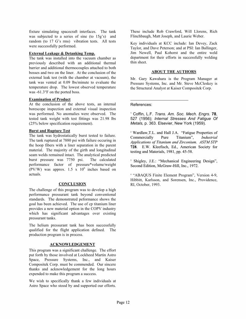
fixture simulating spacecraft interfaces. The tank was subjected to a series of sine (to 15g’s) and random (to 17 G’s rms) vibration tests. All tests were successfully performed.
External Leakage & Detanking Temp. The tank was installed into the vacuum chamber as previously described with an additional thermal barrier and additional thermocouples attached to both bosses and two on the liner. At the conclusion of the external leak test (with the chamber at vacuum), the tank was vented at 0.09 lbs/minute to evaluate the temperature drop. The lowest observed temperature was -61.3°F on the ported boss.
Examination of Product At the conclusion of the above tests, an internal borescope inspection and external visual inspection was performed. No anomalies were observed. The tested tank weight with test fittings was 21.98 lbs (25% below specification requirement).
Burst and Rupture Test The tank was hydrostatically burst tested to failure. The tank ruptured at 7880 psi with failure occuring in the hoop fibers with a liner separation in the parent material. The majority of the girth and longitudinal seam welds remained intact. The analytical predicted burst pressure was 7750 psi. The calculated performance factor of pressure*volume/weight (PV/W) was approx. 1.5 x 106 inches based on actuals.
CONCLUSION The challenge of this program was to develop a high performance pressurant tank beyond conventional standards. The demonstrated peformance shows the goal has been achieved. The use of cp titanium liner provides a new material option in the COPV industry which has significant advantages over existing pressurant tanks.
The helium pressurant tank has been successfully qualified for the flight application defined. The production program is in process.
ACKNOWLEDGEMENT This program was a significant challenge. The effort put forth by those involved at Lockheed Martin Astro Space, Pressure Systems, Inc., and Kaiser Compositek Corp. must be commended. Our sincere thanks and acknowledgement for the long hours expended to make this program a success.
We wish to specifically thank a few individuals at Astro Space who stood by and supported our efforts.
These include Rob Crawford, Will Llorens, Rich Flinchbaugh, Matt Joseph, and Laurie Weber.
Key individuals at KCC include: Ian Devey, Zack Taylor, and Dave Peterson; and at PSI: Ian Ballinger, Jim Newell, Paul Kohorst and the entire weld department for their efforts in successfully welding thin sheet.
ABOUT THE AUTHORS
Mr. Gary Kawahara is the Program Manager at Pressure Systems, Inc. and Mr. Steve McCleskey is the Structural Analyst at Kaiser Compositek Corp.
References: 1 Coffin, L.F. Trans. Am. Soc. Mech. Engrs. 78, 527 (1956); Internal Stresses And Fatigue Of Metals, p. 363. Elsevier, New York (1959). 22 WWaarrddllaaww,,TT..LL.. aanndd HHaallll JJ..AA.. ““FFaattiigguuee PPrrooppeerrttiieess ooff CCoommmmeerrcciiaallllyy PPuurree TTiittaanniiuumm””,, IInndduussttrriiaall AApppplliiccaattiioonnss ooff TTiittaanniiuumm aanndd ZZiirrccoonniiuumm.. AASSTTMM SSTTPP 772288.. EE..WW.. KKlleeeeffiisscchh,, EEdd..,, AAmmeerriiccaann SSoocciieettyy ffoorr tteessttiinngg aanndd MMaatteerriiaallss,, 11998811,, pppp.. 4455--5588.. 33 SShhiigglleeyy,, JJ..EE..:: ““MMeecchhaanniiccaall EEnnggiinneeeerriinngg DDeessiiggnn””,, SSeeccoonndd EEddiittiioonn,, MMccGGrraaww--HHiillll,, IInncc..,, 11997722.. 4 “ABAQUS Finite Element Program”, Version 4-9, Hibbitt, Karlsson, and Sorensen, Inc., Providence, RI, October, 1993.
![, Allen, C., & Rendall, T. (2019). Efficient Aero-Structural Wing AIAA Scitech … · In AIAA Scitech 2019 Forum [AIAA 2019-1701] (AIAA Scitech 2019 Forum). American Institute of](https://img.pdfslide.net/doc/110x75/6089b44b26d0b4646a6cbe59/-allen-c-rendall-t-2019-efficient-aero-structural-wing-aiaa-scitech.jpg)


![2751 WINSTON INDUSTRIAL-WINSTON-final reviewed[1]](https://img.pdfslide.net/doc/110x75/577d2f3d1a28ab4e1eb12f29/2751-winston-industrial-winston-final-reviewed1.jpg)