Embed Size (px)
Citation preview
AIAA 96=3173
Electric Propulsion Optionsfor Mars Cargo Missions
Robert H. FrisbeeJet Propulsion LaboratoryPasadena CA 91109
Nathan J. HoffmanEnergy Technology Engineering CenterCanoga ParkCA91309
32nd AIAAIASME/SAE/ASEEJoint Propulsion Conference and Exhibit
July 1-3, 1996 / Lake Buena Vista, FLFor permission to copy or republish, contact the American Institute of Aeronautics and Astronautics1801 Alexander Bell Drive, Suite 500, Reston, VA 22091
IC]ectric Propulsion Options for h4ars Cargo Missions
Robert 11. }’lisbcc. *h Propulsion I .aboratory
California lnstitutc of “I”cchnologyPasadena CA 91109
and
Nathan J. 1 loffman ~line.rgy ‘1’cchnolc)gy linginccring Center
RocketdyncCanogal%kCA91309
l’his paper summarizes an evaluation of missionperformance (in terms of vehicle mass and triptime) of solar electric propulsion (S];1’) andnuclear electric propulsion (NIT) opcra(ing atpower ICVCIS on the order of 1.5 MWC for Marscargo missions. ‘1’he SEP and NM’ vchiclcs arcboth assumed 10 use lithium-propellant nlagncto-plasmadynamic (MPD) thrus ters wi th anefficiency (electric-to-jet) of 60% at a nominalspecific impulse of 5000 lbf-s/tblll (49 kN-s/kg);the propellant tankage factor is assunlcd to be2.8%. “l’he S1ll> system has a total power, powerconditioning, and propulsion systcm specificmass of 13.6 kg/kWc with a power conditioningsystcm efficiency of 89.6%. “1’he Nlll’ powersystcm uses an SP-100 reactor with dynamicpower conversion (Rankine). q’wo technologyICVCIS were considered for the nuclear-clc.ctricpower system; the baseline system employsrefractory-metals components consistent with thenominal S1’- 1 (IO design. ‘l-his systcm has a totalpower, power conditioning, and propulsionsyslcm specific mass of 24.8 kg/kWc with apower conditioning systcm efficiency of 90.2%.‘1’hc second nuclear-electric power sys(cmoj)cratcs at a lower temperature to allow [hc usec)f non-refractory metals components; this systcm}Ms a total system specific mass of 48.0 kg/kWc(with the same power conditioning systcmefficiency as the refractory-metals systcm). Thebasc]ine refractory-mcta]s NIW system has alower initial mass in low Ilar[h orbit (IMI.lX))and shorter trip time than the non-refractory N]{]’systcm, but the non-refractory NIH> systcm has a
x ‘1’cihnical Group 1.cadcr, Advancedl’ropu]sion Technology Group; MemberAlAA.
? Senior Staff Scientist, Advanced Planning.
potential cost and schcdu]c advan(agc over thercfmctory-N1 W system bccausc refractory mcta]sneed J~ot bc developed and tested. At a given“bus” power level, the SI;P systcm has asomewhat lower IMl .liO and lor]gcr trip time(due in parl to the reduction in power as the SIWvehicle moves away from the sun) as comparedto the ref rac tory-meta ls N];]’ systcm.Interestingly, if the total “bus” power ICVCI of theSIH’ system is increased to give it an IMI.1:0comparable to that of the refractory-metals NIH)systcm, the SEP systcm can have a shorlcr triptime, reflecting the benefit of the lower totalsystcm specific mass of the SI;P systcm.
L 1 lM!xx!lMkm!!Kl B dgnu!
‘1’hc objcctivc of this study was to evaluate themission pcrfornlancc (in terms of vc}]iclc mfissand trip time) of mc.gawatt-class mid-term solarelectric j)rcrpulsion (SIW) and nuc]car electricpropulsion (N};}’) vchiclcs for Mars cargomissions. in particular, wc were intcrcstcd ininvestigating a relatively low-power regime (ea.1.5 MWC) that is significantly lower than thosethat have been considcrcc] in previous studies(typical] y 2 10 MWC) for Mats missions. 1
I.ithium-propellant r]~agr~cto]~lasll] adyrlal]lic(MI’D) thrusters were used for both the S111’ andNIH’ vchic]cs. l]oth high-tcrnpcratur-c refractory -mctals and lower temperature non-refractorymetals SI’-1OO reactor technologies, usingdynamic power conversion, were evaluated.Several l)rcvious papers llavc described thercfrac(ory-metals NllP vchiclc pc)wcr system,2power processing systcms,2!~ and thrustcrs,2and the SI~P vchiclc power c o n d i t i o n i n gsystems.’f “l”his paper will emphasize the S1ll> andnon-refractory-NIW vchic]cs, with the refractory -NI{I’ systcm used as a baseline for comparison.
(h~yi~llt @ 1996 by [h Anlcrican lnsliluk of Acl(mautics and Astrona~]tirs, Inc. All righ(s rcscf vcd.
‘1’hc basic mission scenario involves transporting
!2a 90-n] ctric ton Ml’) payload, the Mars 1.anctcr
5 from a Soo-km al[i[u(ic lowModule (MI.M) ~-}Iar[h orbit (1.1X1) to a 6000-km altitude orbitaround Mars. “J:his orbit was selected because it isat the same altltude as Phobm. “1’here arc scvmlpotential benefits to this approach. l;rom ascience perspective, Phobos represents a likelystopover for a piloted mission because of intcreslin Phobos as a “Genesis rock” whose structureand composition have not changed since theformation of the solar system, From a practicalpoint of view, “landing” the N];]’ vehicle in oneof the many craters on Phobos (after deployingthe payload in the 6000-kn~ orbit) could provideshielding to nearby vehicles or people. IJinalty,power from the NJY or SI~P power systemscould bc used to extract resources such as waterfrom l’hotms for production of propellant orother u scful materials.
A one-way (delivery) mission is assumed, withthe vehicle left at Mars. Al[hough both the SITand N1lP vchic]cs am initially dcployext in a 5(K)-km 1.1;0, the NI{P reactors arc not started untilthe Nlll’ vehicle is in a 1000-kn~ altitude Ilarihorbit to ensure that, in the unlikely event of tisystcm Fdilure, the vehicle remains in orbit asufficicnt]y long time for reactor radiation todecay to acccptab]c ICVCIS. An cm-board chemicalbipmpcllant propulsion system is used for theinitial 500-to-1000” km N]!]’ vehicle orbittransfer. III contrast, the S1;1’ system beginsoperation directly from l,EO and, thus, does notrcq u i rc the N]{I’ vehicle’s bipropopcllantpropulsion system.
I;or b o t h the NIW a n d SIW v e h i c l e s , aI~~OI]ol~rol)cllaIlt propulsion attitude controlsys(c.m (ACS) is used for a((itude control whenthe Ml’]) thrusters arc not in usc an(i fol-“landin~” on Phohos if required. We assumed achemical bipropcllant “dual-mode” (N’1’0/N21 LI)propulsion system (Isp = 330 Ibf- s/1 bm ) (inwhich the. bipropcllant orbit tmnsfcr main enginefuel shares common tankage with the ACSsystcm) for the initial NI}P vehicle’s orbit transfcland a l~~ol~c)j>ro]jcllal]t (N21 1~) ACS system (ls1)= 220 lbf-s/lblll). “l-he total chcmica] propulsionsystcm has a tankage factor of 1690 (i.e., the. totfil“dry” mass of the chemical propulsion system is16% of the total mass of propellant). ];inally,when operating, the MPD thrusters, w}~ic}~ arcused in pairs, are gimbaled to provide therequired vchiclc attitude control.
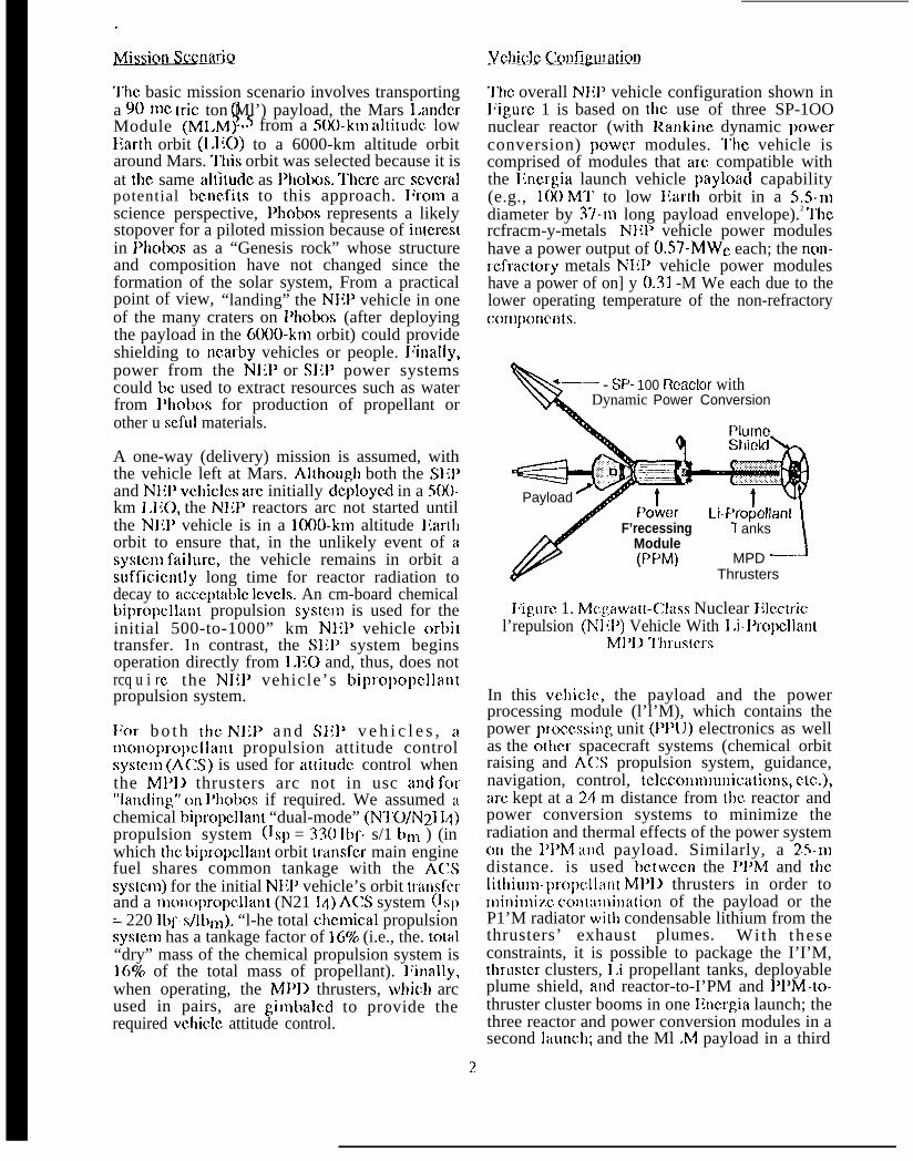
‘1’hc overall Nli}’ vehicle configuration shown inl~igurc 1 is based on the use of three SP-1OOnuclear reactor (with Rankine dynamic powerconversion) power modules. ‘1’he vehicle iscomprised of modules that are compatible withthe Ilnergia launch vehicle payloac] capability(e.g., 100 Ml” to low I{ar[h orbit in a 5.5-lNdiameter by 37-nl long payload envelope).2 ‘]”hercfracm-y-metals N1{P vehicle power moduleshave a power output of 0.57-MWe each; the non-rcfractory metals NliP vehicle power moduleshave a power of on] y 0.31 -M We each due to thelower operating temperature of the non-refractoryCOnlponcnts.
\
~— - SP- 100 Reaclor withDynamic Power Conversion
\ Q Em%.Payload
r
Poker
/
F’recessingModule(PPM)
Li-Pro~ellant1 anks
MPD ‘-1
Thrusters
I~igurc 1. Mc~awatt-Chrss Nuclear Iilcctricl’repulsion (Nl ;1’) Vehicle With 1.i-l’ropellant
M1’1~ “I”hrustcrs
In this vchiclc, the payload and the powerprocessing module (l’l’M), which contains thepower proccssi]~g unit (PPU) electronics as wellas the olhcr spacecraft systems (chemical orbitraising and ACS propulsion system, guidance,navigation, control, tclccoIlllll~l[licatiolls, etc.),arc kept at a 24 m distance from the reactor andpower conversion systems to minimize theradiation and thermal effects of the power systemotl the 1’I’M and payload. Similarly, a 25-nldistance. is used bctwccn the I’PM and thelitllil]l]l-])]o])clliil~t MI’IJ thrusters in order tominimi~.c ccm[:ilnination of the payload or theP1’M radiator with condensable lithium from thethrusters’ exhaust plumes. With theseconstraints, it is possible to package the I’I’M,thrustc.r clusters, l.i propellant tanks, deployableplume shield, an(i reactor-to-I’PM and PPM-to-thruster cluster booms in one Encrgia launch; thethree reactor and power conversion modules in asecond Iauncll; and the Ml .M payload in a third
2?
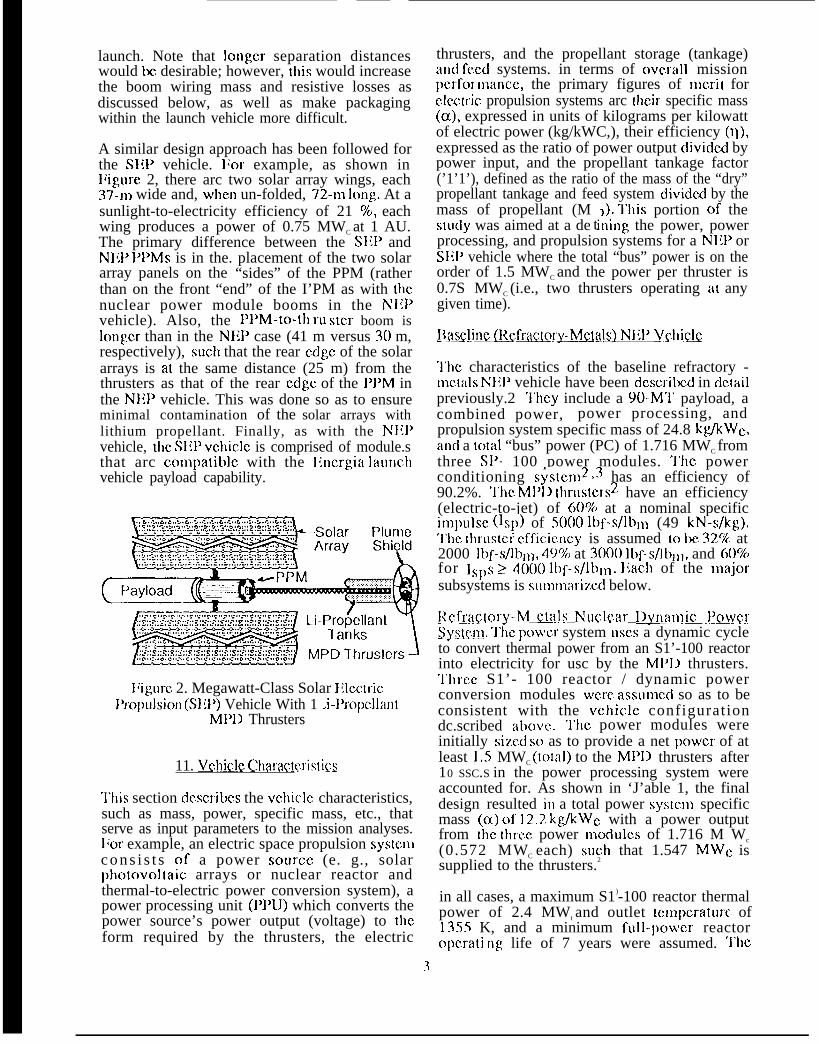
launch. Note that longer separation distanceswould be desirable; however, this would increasethe boom wiring mass and resistive losses asdiscussed below, as well as make packagingwithin the launch vehicle more difficult.
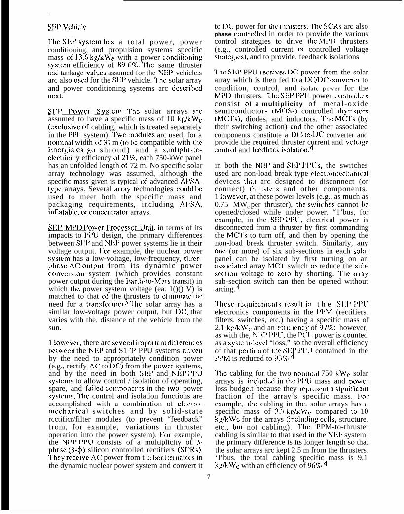
A similar design approach has been followed forthe S1ll> vehicle. l;or example, as shown inI;igurc 2, there arc two solar array wings, each37-nl wide and, when un-folded, 72-n] long At asunlight-to-electricity efficiency of 21 %, eachwing produces a power of 0.75 MWC at 1 AU.The primary difference between the SIiP andNlil’ 1’I’Ms is in the. placement of the two solararray panels on the “sides” of the PPM (ratherthan on the front “end” of the I’PM as with thenuclear power module booms in the NI~Pvehicle). Also, the ]’]’M-tO-th II IStCr boom islonger than in the NIIP case (41 m versus 30 m,respectively), SUC}l that the rear edge of the solararrays is at the same distance (25 m) from thethrusters as that of the rear edge of the 1’I’M inthe NJIP vehicle. This was done so as to ensureminimal contamination of the solar arrays withlithium propellant. Finally, as with the N1iPvehicle, dlc Slil> vclliclc is comprised of module.sthat arc com])atiblc with the llnergia laut]chvehicle payload capability.
——.. b..:.. G.#..-> .:.. >..t..:.. G.t... G,0,,5. %.. >.5..:..9. .>. O..:.. O.O,, . . . .. . . . . . . . .. . . .. . . .. . . . , - .,:.....:
.,.. .=..=,: ,,... ,,, .-..,9 , =, . =,.-...-.
.~. . ~, .-.,,... ,=, ,.-, .~, ,.. .+. ,.-. ~.. .~
. . -...,,-,- ,,. ,, .,,.... , .,,;..,,.
*-w
l:igure 2. Megawatt-Class Solar IllmricI)ropulsion (SIT) Vehicle With 1 .i-l’ropcllant
Ml’I) Thrusters
11. Vchicl& Ch?ractcris!ks
‘1’his section dcscribcs the vchiclc characteristics,such as mass, power, specific mass, etc., thatserve as input parameters to the mission analyses.lior example, an electric space propulsion sysle.mc o n s i s t s of a power source (e. g., solarphotovoltaic arrays or nuclear reactor andthermal-to-electric power conversion system), apower processing unit (PPU) which converts thepower source’s power output (voltage) to theform required by the thrusters, the electric
thrusters, and the propellant storage (tankage)al)d fcwd systems. in terms of ovmll missionpcrfol mancc, the primary figures of merit fore.tcctric propulsion systems arc t}lcir specific mass(cx), expressed in units of kilograms per kilowattof electric power (kg/kWC,), their efficiency (T)),expressed as the ratio of power output divided bypower input, and the propellant tankage factor(’1’1’), defined as the ratio of the mass of the “dry”propellant tankage and feed system diviclcd by themass of propellant (M ~). “1’his portion of the
tstudy was aimed at a de ining the power, powerprocessing, and propulsion systems for a NIH’ orSI{P vehicle where the total “bus” power is on theorder of 1.5 MWC and the power per thruster is0.7S MWC (i.e., two thrusters operating at anygiven time).
jlfl~~finc (Refraclwy-Mctak) NIT VKlliclc
‘1’k characteristics of the baseline refractory -mc.tals hT1lP vehicle have been dcscribcd in detailpreviously.2 ‘1’hcy include a 90-M’1’ payload, acombined power, power processing, andpropulsion system specific mass of 24.8 kg/kWc,ancl a total “bus” power (PC) of 1.716 MWC fromthree S1)- 100 power modules. ‘l”hc powerconditioning systcn12 ~3 has an efficiency of90.2%. ‘I”hc Ml’]] thrusters2 have an efficiency(electric-to-jet) of (W% at a nominal specificimpu]sc (]sl)) of SOOO lbf-s/lbrll (49 kN-s/k~).‘1’hc thrastcr cfficic.ncy is assumed to be 32% at2000 lbf-s/lblll, 49% at 3(K)O lbf-sflbll], and 60%for 1s1)s >4000 ]bf-s/lbn~. ]iach of the l~lajorsubsystems is summarized below.
RcfL~GL~I.v-Mct i~ls N@~ar 1~.ymtnlti’lw&r~yste.c~. ‘1’hc power system uscs a dynamic cycleto convert thermal power from an S1’-100 reactorinto electricity for usc by the Ml’]) thrusters.‘1’hrcc S1’- 100 reactor / dynamic powerconversion modules were assumcci so as to beconsistent with the vc}licle configurationdc.scribed atmvc. ‘1’hc power modules wereinitially sized so as to provide a net power of atleast 1,5 MWC (IOM1) to the Ml’]) thrusters after10 SSC.S in the power processing system wereaccounted for. As shown in ‘J’able 1, the finaldesign resulted in a total power systcm specificmass (CX) of 12.2. kg/kWc with a power outputfrom the thre.c power mc~clules of 1.716 M Wc
(0.572 MWC each) such that 1.547 MW{: issupplied to the thrusters.2
in all cases, a maximum S1)-100 reactor thermalpower of 2.4 MWt and outlet tcmpcraturc of1355 K, and a minimum full-pc)wcr reactoropcrati ng life of 7 years were assumed. ‘1’hc
3
dynamic powc) convers ion systcm uses apmassium (K) Rankinc engine with a sirlglc-shaftturboaltcrnatm (’l-A), with an inlet tcmpcraturc of1275 K and at) outlc( tcrnpcraiure of 849 K for agross cycle efficiency of 2.4.5% and an overallthermal-lo-ncl clcc(ric output efficiency of24.3%.2
NIIJ’-MI:1) ~@vCr Pro~.~Sc_v U nfi. A powerprocessor unit (PPIJ) for aJI Ml’]] tbrustcr mustsupp]y voltages and currents to different clcrrrcntsin the thruster. In general, the PPIJ mus( providelow voltages (e.g., 1 ()() V 1X2) at high powers(e.g., 750 kWe) for the Ml]l) discharge, and lowvoltages at low powers (e.g., a total of 60 kWc,)for components related 10 opcralion of the MPIIthruster, such as the applied-ficlci h41’11 magnets(25 kWc pcr thruster), (hrustcr gimbal actuators,heaters, etc., as well as for misceilanc.ous vchic]c“l~otlsckcc~>il~g,” functions.
“1’hc primary driver in (ems of N1;I’-M1}lI PIWdesign is the M1’11 thruster’s rcquircrncnt for lowvoltage and nigh power, which results in arcquircmcnt for high-current capacity dcviccs(c.&, 1300” to 7500” Amps). Also, [hC f)]]u llluStbc designed to accommodate startup andshutdown transients, and be capable of isolatingthruster and l’1’lJ component fi~ilurcs withoutcompromising the remainder of the power orpropulsion systcm. ‘1’bus, the P1’lJ consists ofboth a primary high-powc.r systcm and a smaller]ow-power- power conditioning unit (1’C;lJ). l;c)rconvcnicncc, the l~PIJ electronics components(rcctificrs, filters, etc.) and switches arc matedscparatc]y from the compcmcnt “bus bar” wiring(t)oth within the I’1’M as WC]] as in the longbooms between the PPM and the thrusters [30 m]or bctwccn the I’I>M and the nuclear J~owcrsys(cms [24 m]). In fi~ct, bccausc of the high JX:currents cncountmcd (e. g., as much as 7500” A at1()() V IX for the cables running to each thrus(crcluster), the wiring is almost two times heavierthan the. l’1’lJ electronics and switches (e. g., aspecific mass of 6.7 kg/k Wc for the cablingversus 3.2 kg/k Wc for the c.le.c[ronics andswitches). 1 lowevcr, the cab]ing is also used toform the main structural clc.mcnts for the reactorand thruster booms, thus partially offsetting thec a b l i n g m a s s pcna]ty. l:inal]y, the I’PLJelectronics components in the I’PM (rcctificrs,filters, switches, etc. ) and the cabling havecomparable 10SSCS and corresponding cfficicncics(-97%); however, bccausc t}]c P(X1 power iscounted as a “loss” in the PPM conlponcllt’spower budget, their net efficiency is rcduccd to937..2.,3
4
MI~I) ‘17tlrL!slGm~~lL~])~Ml~ hr~k~~y~~~lm.~’hc total M1’1~ thruster systcm includes the Ml’]]thrusters, thruster gimbals, lithium (I .i) propellantvaporizer and flow contmllcr, plume shic]d, and1,i propellant storage and fe.cd systems. “1’woclusters of thrusters arc used with onc engineoperating in each cluster to provide for attitudecontrol (luring thruster operation. l:ach clustercontains 8 h41’1> thrusters for a total of 16thrusters to satisfy the cunlulative engine. runtime. ‘1’hc overall specific mass of the thrustersubsystem (including plume shield) is 3.2k@Wc with an clc.ctric-to-jet po cr cfficimcy of60% at an lsp of 5000 lt)f-S/lbrll. Y
‘J’he. tank design assumes the propcllan( to bcc.lclnc.ntal lithium; bccausc the propellant is in thesolid phase during laur~ch to 1.1;0, minimal tankstrcng,th is required (i. e.., only sufficient s[rmgthm contain the propellant mass as a liquid at verylow ])rcssurc in space). Waste heat fmm thethrusters is used to melt the 1.i at a tmpmturc of181 ‘~. l’wo tanks, locatcct on either side of the1’1’M-to-thruster cluster boom, arc used to storethe total propellant requirc(i. “1’hc tanks (andthruster waste-} lcat [ransfcr s stem) have atankage fraction (’l’l;) of 0.0278. 2’
Systems-].cvci vl..lrQs. ‘1’able 1 shows lhcsystems-lcvci values c)f the mass, specific mass,power (and losses) of tile power, poweri~roccssing,, and thruster subsystems. In or(icr to(icIivc the “nominal” systcm pramctcrs, wc f]rstdetermine.d the mass, cfficicncy, waste heat,volume, tankage factor, CIC. for each of ti~c majorsys t ems bascci on a point design using anassumc(i power inl)ut (e. g., 1.5 M WC) orproi)cllant mass (e.g., 50 M’J’), and then scaledthe systems to corrcspon[i to the actual poweravailab]c or the actual J)ropcllant mass ricrivcdfrol]l tile (ictailcci Illission analysis. ‘1’tlis isiilustr:ttcd in ‘i’able 1 for the calculation of imwcran(i “cffcclivc” si)ccific mass (dcfine(i as the mass(iivicicci by the. total “t)us” power, I’c,) based onti~c actual specific mass and efficiency cicrivcdfroln a point design for each of the majorSyslcms.
l~in:tlly, the Mi’11 li[tl iurn propellant tankagefaclor (’1’1:) is 2.8%. ‘i’he cilcrnical propulsionsystcm i~as a ‘i’l; of 16%; the duai-nmic mainengine has an Isll of 330 lt~f-s/lb113 and the AC3ti~rustcrs have an Isl) of 220 lbf-s/ibl~~. lastly, a.mass of onc r)lctr;c ton ismisceilane.ous spacecraftguidance, navigation, andtciccc)rlllll~lrlic: itiolls, ctc.2
;Ilocatcd fcm ‘thesystems such ascc)n[rol (GN&C),
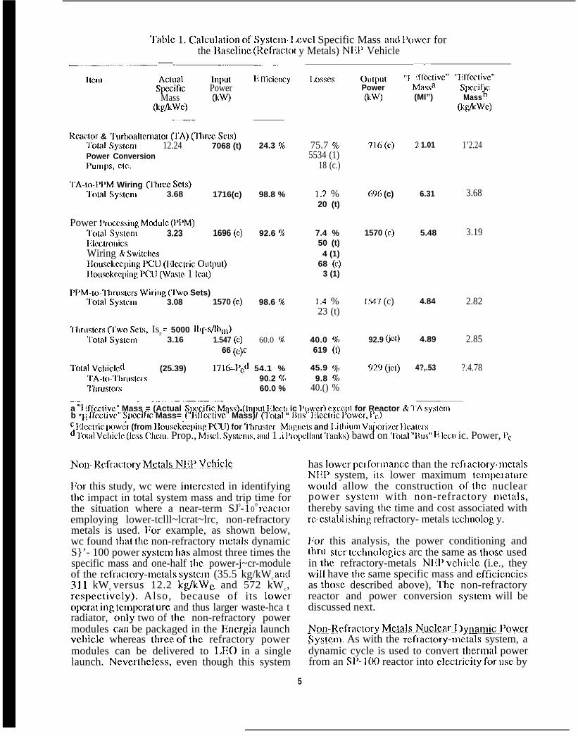
‘1’able 1. ~alculaticm of Systcm 1,CVC1 Specific Mass and l’ower forthe IIascline (Rcfmctol y Metals) N];]’ Vehicle
—..————— -—-. _— ———— ——
ltcrn Ac(ual InpulSpccitic Power
Mass @w(kglkwc)
————
Rcackx & ‘1’urbodtcrna[ot (TA) (Ilmec SCLS)Total Syslcm 12.24 7068 (t)Power ConversionPumps, clc.
l’A-to-PPM Wiring (Ihmc SC{S)l’olal Sysmm 3.68 1716(c)
Power l’rowssing Modulc (PPM)‘1’otal systcm 3.23 1696 (c)lilcmo]licsWiring & Swilcbcsllousckec.ping lKXJ (Elcclric ou[jmt)}Iousckw.ping PCXJ (Waslc 1 lcat)
I’}>M-K-~hruskXs wiring (1’wo Sets)l’otal Systcrn 3.08 1570 (c)
I}lrustc.rs (’I’WO SCLs, Isp = 5000 lbf-sflbn])T’otal SysWn 3.16 1.547 (c)
66 (c)c
I\ fficic.ncy
24.3 %/
98.8 %
92.6 %
98.6 %
60.0 %
~’otal Vchiclcd (25.39) 1716=1’J 54.1 %l’A-ti)-”1’tlrilslcrs 90.2 ?47’hrustcrs 60.0 %
1 L)ssc.s
.—
75.7 %5534 (1)
18 (c.)
1.2. %20 (t)
7.4 %50 (t)4 (1)
68 (C)3 (1)
1.4 %23 (t)
40.0 %619 ([)
45.9 %9.8 vu
40.() %
Outpu(Power(NV)
716(C)
696 (c)
1570 (c.)
1.547 (c)
“~ [ff~,liv~” “~{ff~.tivc”Mawa Spczif c(MI”) Mass t!
(t@wc)
? 1.01
6.31
5.48
4.84
92.9 (ict) 4.89
9?.9 (jCl) 4?,.53
1’2.24
3.68
3.19
2.82
2.85
?.4.78
-. —— .- .-. .—-—. ——— —a “IL ffcziivc” Mass = (Actual Spmific hfass) ● (Input lilccII ic l’fwcr) cxcc.l)t for Reactor & 7’A systcmb ‘l]\ ffeC[ivc” Slwzjfic Mass= (“r~ffc~[iv~” Mass)/ (’J’otal “ Iius” }ilc.clric POWCr, }’c,)c I{lcctric Pow;r (from 1 lou.sck;q)ing PCU) for ~hr~lslcr h’lag[icLs and 1.i[tlium Va~mim IIcalcrsd ‘1’olal Vchiclc (Icss (llc.m. Prop., Mi.scl. Systcrns, and 1 i l’iol~tlan[ ‘1’allks) bawd on I’olat “lIUS” l{ IC.CII ic. Power, I’c
~MI- ]<cfract~ry M_etals__N1_ll’ V.ChiC!C
l;or this study, wc were intcrcstcd in identifyingtbc impact in total system mass and trip time forthe situation where a near-term SJ)-10
0 rcac[oremploying lower-tclll~lcrat~lrc, non-refractorymetals is used. llm example, as shown below,wc found that the non-refractory metals dynamicS}’- 100 power systcm bas almost three times thespecific mass and one-half the power-j~cr-moduleof the rcftiictol-y-l~~ctals systcm (35.5 kg/kWc and311 kWc versus 12.2 kg/kWc and 572 kWc,rcspcctivcly). Also, because of its 10WCIopcrat ing tcmpcmt ure and thus larger waste-hca tradiator, only two of the non-refractory powermodules GM be packaged in the Hncrgia launchvchic]c whereas tlwce of the refractory powermodules can be delivered to 1.110 in a singlelaunch. Ncvcrthc]css, even though this system
has ]owcr pmformancc than the rcflactory-mc[alsNIT system, its lower maximum tcn~pcraturcwould allow the construction of tbc nuclearpower systcm with non-refractory mc.tals,thereby saving the time and cost associated withrc-cstabl ishing refractory- metals tcchnolog y.
];or this analysis, the power conditioning andthIWSt Cr tc.chno]ogics arc the same as those, usedin the refractory-metals N1~P vchiclc (i.e., theywill have Ihe same specific mass and cfficicncicsas tbosc described above), ‘1’hc non-refractoryreactor and power conversion systcm will bediscussed next.
NQ~-J\cfractory M.e&ls._N.@mLl JyWltiJ’Qw?JSySIem. As with the rcf~actory-mc(als system, adynamic cycle is used to convert tbcrmal powerfrom an SP- 100 reactor into clcc[ricity for usc by
5
the Ml’I) thrusters. l’hc S1]- 100 reactor/dynamicpower conversion nmdL]lcs were assumed to bcconsistent with the overall vchic]c configurationdescribed above, although more than thre.c powermodules may need to be attached to the PPM toprovide sufficient power bccausc of the lowerpower pcr module in the non-refractory metalssystcm. ‘1’hc usc of non-refractory metals in thenuc]car power systcm results in a total vchiclcpower, power conditioning, and propulsionsystems specific mass of 48.0 kg/kWc with thesame power conditioning system efficiency as thebaseline NIW system (90.2%).
}:or the refractory-metals reactor, the S1’- 100reactor thermal power is 2.4 h4Wt with a reactorout]ct tcn~pe.raturc of 1355 K. I:or the. non-rcfractory metals systcm, the 2.4-MWI reactoroutlet tcmpcraturc is lirni[ed to 1010 K, which isabout the maximum temperature for usingnon-refractory metals. IIoth Rankinc and llraytonthermal-to-electric power conversion systemswere evaluated, with the Rankinc system havingthe better performance. In the Rankinc cycle,potassium’s large sJlccific volume at the lowerturbine outlet te.rnpcraturc woulft lead to anunreasonably large, massive turbine. l’hcrcforc,wc chose ccsium as the working fluid for thenon-rcfractoly metal Rankinc cycle. ]Iccause.non-refractory metal is susceptible to attack bylithium, wc chose to rcplacc lithium withpotassium as the reactor coolant. l;inally, wcassumed that changing the reactor coolant wouldnot change the reactor mass significantly.
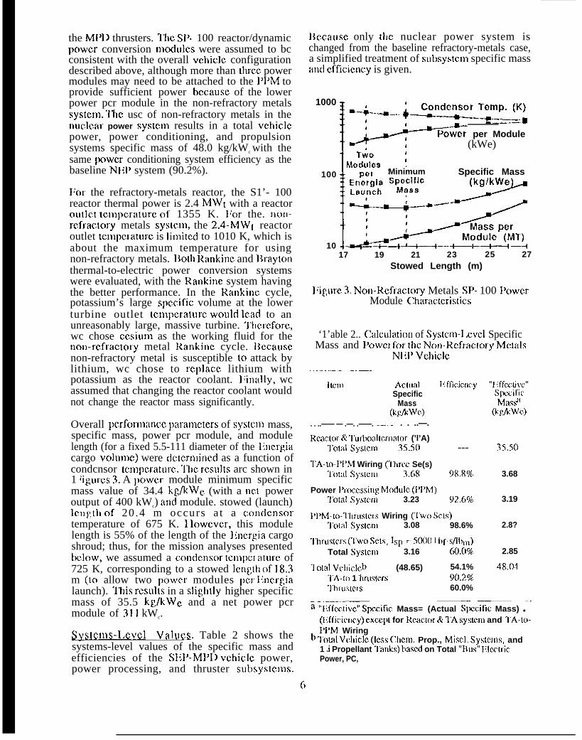
Overall pcrfomance J)aramcters of systcm mass,specific mass, power pcr module, and modulelength (for a fixed 5.5-111 diameter of the llncrgiacargo voluJnc) were dctcrmincd as a function ofcondcnsor tcmpcraturc. ‘l”hc rcsul(s arc shown in1 ~igurcs 3. A pc)wcr module minimum specificmass value of 34.4 kg/kWc (with a net poweroutput of 400 kWc) and module. stowed (launch)length of 20 .4 m occurs a t a condcnsortemperature of 675 K. 1 lowcver, this modulelength is 55% of the length of the llncrgia cargoshroud; thus, for the mission analyses presentedbelow, we assumed a condcnsor tcmpc.r aturc of725 K, corresponding to a stowed ]cngth of 18.3m (to allow two pc)wcr modules pcr l{ncrgialaunch). ‘1’his rcsul(s in a slighl]y higher specificmass of 35.5 kg/kWc and a net power pcrmodule of 311 kWc.
s!Stcnls-1.cyel Va lLJGS. Table 2 shows thesystems-level values of the specific mass andefficiencies of the SEP-MPI1 vchiclc power,power processing, and thruster subsystc.ms.
]Iccausc only t}lc nuclear power system ischanged from the baseline refractory-metals case,a simplified treatment of subsystcm specific massand cftlcicncy is given.
1000
I ,~
“+-””--4=W?xTyY_Q!:
L“ :Po”w% per Module
(kWe)
LModulos :
100 Minimum Specific MassEn~~ia S::~~CLaunch ,
--”s10 +~–~+4 —-J
17 19 21 23 25 27Stowed Length (m)
l;igurc 3. Not~-Rcfractoly Metals SP- 100 PowerModule Gamctcristics
‘1’able 2.. calculation of Systc.m-l -WC] SpecificMass and POWCI fbr t}~c Ncm-Rcf~actory Mctrrls
NIH’ Vchiclc. . . .. —.— — .—. ———
Item Actual I{ fficicncy “}; ffcllivc”Specific Spc..if[c
Mass h4as@(kp,/kwc) (l@Kwc)
. . ..—— — .—. .——. —-.—— . . ..—.
Rcaclor & I’urboallcrnator (’l’A)~’otal Syslcm 35.50 --- 35.50
l’A-tmI’f’hf Wiring (’I’hrcc Se(s)“1’olal System 3.68 98.8% 3.68
Power I’roccssing Motfrrlc. (PI’hl)‘l’o(al Syslcm 3.23 92.6% 3.19
i’I’M-to-l’llrtlstcrs Wiring (’1’wo SC.(S)‘1’otnl Systcm 3.08 98.6% 2.8?
I’hrus[crs (’I’wo SCM, lsl) = 50(KJ I bf-s/lblll)Total Systc.m 3.16 (0.0% 2.85
~otaI Vciliclc.b (48.65) 54.1% 48.01l’A-to 1 ‘hr-us[c.rs 9(1.2%‘t?rruslcrs 60.0%
; “liffcc.tivc” Spccifk Mass= (Actual Spc;i~c Mass) ● ““-fJ;fficicncy) c.xccI~t for Rcaclor & 1’A systcm and ‘l’A-to-J’PM Wiring
b “1’crtal Vc.hiclc. (Icss Chcrn. Prop., Miscl. Syslcms, and1 .i Propellant larks) trascd on Total “Bus” ElcclricPower, PC,
6
‘1’he S111’ systcm has a total power, powerconditioning, and propulsion systems specificmass of 13.6 kf~We with a power confii(ioningsystcm efficiency of 89.6%. ‘1’hc same thrusterand tankage values assumed for the NIH’ vehicle.sarc also used for the S1;1’ vehicle. “1’he solar arrayand power conditioning systems arc dcscribcdnext.
SIT 1’0 wH__sySfLnL ‘l’he solar arrays arcassumed to have a specific mass of 10 kg/kWc(cxclusivc of cabling, which is treated separatelyin the 1’}’1) system). “1’wo modules arc used; for anomin:il width of 37 m (m bc. compatible with thel;ncrgia cargo s h r o u d ) a n d a sunlight-to-clcctricit y efficiency of21 %, each 750-kWc panelhas an unfolded length of 72 m. No specific solararray technology was assumed, although thespecific mass given is typical of advanced APSA-typc arrays. Several array technologies could beused to meet both the specific mass andpackaging requirements, including APSA,inftatab]c, or conccntmtor arrays.
sl?l’- Ml’I) I’QwErlYJQQMQrMti3. in terms of itsimpacts to I’1’U design, the primary differencesbetween SIW and NJ;}’ power systems lie in theirvoltage output. };or example, the nuclear powersystem has a low-voltage, low-frequency, thrcc-phasc A(2 output from its dynamic powercxmvcrsicm system (which provides constantpower output during the liarth-to-Mars transit) inwhich [he power system voltage (ea. 1()() V) ismatched to that of the thrusters to clitninatc tllcneed for a transfcmncrs “1’hc solar array has asimilar low-voltage power output, but IX, thatvaries with the, distance of the vehicle from thesun.
1 lowcvcr, there arc scvcr:il inq)ollanl diffcl’cnccsbctwc.cn the NIT and S1 11’ PPU systems drivenby the need to appropriately condition power(e.g., rectify AC to )X2) from the power systems,and by the need in both S111’ and Nljl’ I’I’USyste,lns to allow control / isolation of operating,spare, and fi~ilcd mmponcnts in the two powersystems. ‘1’he control and isolation functions areaccomplished with a combination of clcctro-nlcch:inica] swi tches and by so l id-s ta tercctificr/filter modules (to prevent “feedback”from, for example, variations in thrusteroperation into the power system). I:or example,the NI1}’ PPU consists of a multiplicity of 3-phasc (3-$) silicon controlled rectifiers (S(XS).“1’hcy rcccivc AC power from t urboal ternatcws inthe dynamic nuclear power system and convert it
to IX power for the thruslcrs. ‘1’hc S0<s arc alsophase control]cd in order to provide the variouscontrol strategies to drive the M1’1~ thrusters(e.g., controlled current 01 controlled voltagestra[c.gies), and to provide. feedback isolations
‘l”hc S111’ PPU rcccivcs IX power from the solararray which is then fed to a IKYIX; convcrler tocondition, control, and isolate power for theMl’]) thrusters. “1’hc SIT PPU power control]crsconsist of a multiplicity of meta l -oxidesemiconductor- (MOS-) controlled thyristors(MCH’S), diodes, and inductors. “1’hc M~’1’s (bytheir switching action) ancl the other associatedcomponents constitute a ]1(~-to- ])~ converter andprovide the required thruster current and voltageccm(ro] and fcc(iback isolation.4
in both the NIT and Sljl’ PI’US, the switchesused arc non-load break type c.lcctlol~~cc}la[licaldevices that arc designed to disconnect (orconnect) thrus(crs and other components.1 lowcvcr, at these power levels (e.g., as much as0.75 MWC per thruster), the switcilcs cannot beopened/closed while under power. “1’bus, forexample, in the S111’ I’I’IJ, electrical power isdisconnected from a thruster by first commandingthe M(H’s to turn off, and then by opening thenon-load break thruster switch. Similarly, anyone (or more) of six sub-sections in each solarpanel can be isolated by first turning on anassociatcxl array hfi~’1’ switch tc) reduce the sut~-scction voltage to zero by shorting. “1’hc arlaysub-section switch can then be opened withoutarcing. 4
‘1’hcsc rcquircmcnts result in t h e SIIP I’PUelectronics components in the 1’1’M (rectifiers,filters, switches, etc.) having a specific mass of2.1 kg/kWc, and an cfficic.ncy of 9“)%; however,as with the, N]{]’ 1’1’U, the P(Y.J power is countedas a syslen-lcvc] “loss,” so the overall efficiencyof that pcmion of the S111’ PI’(J contained in the1’1’M is reduced to 93%.4
“1’hc cabling for the two nonlina] 750 kWc solararrays is illcludcd in the l)l’U mass and powc.rloss budge.t because they rcprcscnt a significmtfraction of the array’s specific mass. l%rexample, the cabling in the. solar arrays has aspecific mass of 3.7 kg/kWc compared to 10kg/kWc for the arrays (inclu(iing CCIIS, structure,etc., but not cabling). ‘1’hc PPM-to-thrustercabling is similar to that used in the NliI’ system;the primary difference is its longer length so thatthe solar arrays arc kept 2.5 m from the thrusters.‘J’bus, the total cabling specific mass is 9.1kg/kWc with an efficiency of 96%.4
7
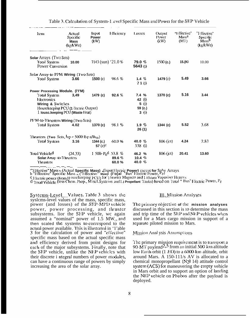
Table 3. ~alculation of System-1 ,CVC1 Specific Mass and 1’OWCJ for the SIW Vehicle———.. . ..— ——— -- .—— — _—— .— ----
ILcm Actual hlpllt Iift’lcicncySpmific Power
Mass @w(t@kwc)
—— . . . ——. .
Solar Arrays (TWO SCLS)3’Olal Sysmm 10.00 7143 (sun) ‘21.0 %Power ~onvcrsion
Sohir Array-to-P1’M Wiring (T’wo SC(S)~’olal Syslcm 3.66 1500 (c) 98.6 ~0
Power Processing Module. (l’I’M)“1’otal Syslcm 3,49 1479 (c) 92.6 %l;lcctronicsWiring & Swi[chcsIIousckwping PCU (1 ilcctric Ou@I[)1 Iousc.keeping PCU (Waste IIcat)
P} ’M-to-3 hrus[crs Wiring (1’wo SCLS)“1’olal Systcm 4.02 1370 (c) 98.1 %
Ihruslcrs (Two ScLs, Isp = S(KXI lbf-#lbnl)“1’olal Syslcrn 3.16 1344 (c.) 60.O %
57 (c)~
Tolal Vchiclcd (2A.33) I mo-]’cd 53.8 %Solar Array -to-7 hrusLc.rs 89.6 %Ihruslcrs 60.0 %
———.——. . . —. —. —.. —...
I .oSscs output “I mcx;c”
79.0 %5643 (()
1.4 %? 1 (t)
7.4 %42 ([)
5 (1)59 (c.)
3 (1)
1.9 %26 (1)
40.0 %538 (t)
46.2 %10.4 ?40
40.0 %
I ‘oiler&w)
1500 (c.)
1479 (c.)
1370 (c)
1344 (c)
806 (jcr)
806 (jCl)
(MI’)
15.(KI
5.49
5.16
5.52
4.24
20.41
“l; ffcctivc”Spczif_c
(Maw )(kglkwc)
10.00
3.66
3.44
3.68
2.83
13.60
a “JiffcC[ivc” Maw = (Aclua] Specific Mass) ● (lniul I{lc.ctric Power) cxccpl for Solal Arraysb ‘ir~ffcctivc” Spxific Mass ~ (“~lffe~livc,” Maw)/ (l’o[al “Rus” Illcclfic P(nvCr, T’c)C ~~lczlric ~mwcr (frorll ~] f)tlsc,kc,ping, ]~1]) for “1 llr(ls~cr Magll~,[s and 1,i[ltium Varx)riz.cr ][calcrsd ~o[al Vchjc]c, (]cs~ ~h~n~, proJ)., M iscl. Sys[crns, ~rld 1.i Propellant ‘1’anks) bawd on ‘1’Olal “ l~us” ~~lcc~ic ~’owCr, 1’c
SysteJ~)s-l.eve~.,. Valtlcs. Table 3 shows thesyslcms-level values of the mass, specific mass,power (and losses) of the SIH’-MPIJ vchiclcpower , power process ing, and thrustersubsystems. lior the SIW vehicle, wc againassumed a “nominal” power of 1.5 MWC, andthen scaled the systems to coxmspond to theactual power available. ‘1’his is illustmted in ‘1’able3 for the calculation of power and “cf”fcctivc”specific mass based on the actual specific massand efficiency derived from point designs foreach of the major subsystems. l:inally, note thatthe S11}’ vehicle, unlike the Nl:l’ vchiclcs withtheir discrete i ntcgral numbers of power Inodulcs,can have a continuous range of powers by simplyincreasing the area of the solar array.
~11.Mission Analyses
‘1’hc prinlary objcctivc of the mission analysesdiscussed in this section is 10 determine the massand trip time of the S111’ and NIIP vchiclcs wl]cnused for a Mars cargo mission in support of ascpara[e piloted mission to Mars.
.M_i>Sior] Aml ysis .AssuIIlpt i~ns
‘1’hc primary mission rcquircmcnt is to trans]ml a90. M-l’ paY]oad2>5 from al] initial Sofl-km altitudelow llal[h orbit (1 .};0) to a (X)o(-km altitude, orbitaround Mars. A 150-111/s AV is allocated to achemical monopropellant (N21 14) attitude controlsystem (ACXS) for maneuvering the empty vehicle. .in Mars orbit and to support an option of land]ngthe Nl13’ vchiclc on Phobos after the payload isdeployed.
8
A“ one-way (delivery) mission is assunml, withtbc vchiclc left at Mars. Also, as discussedabove, the NIWvchiclc’sr cactorsare not starteduntil thcvchicle is in a 1000-kn~ llarth orbit. A262-1~~/s AVisrwl~iircd for[hc5(K1-to- loOO-kn~altituctc transfer. ‘1’his AV (and bipmpcllantchemical propulsion system) is not needed for theS1{1’ vchic]c because it can bc started at the initial500 km 1.110 altitude.
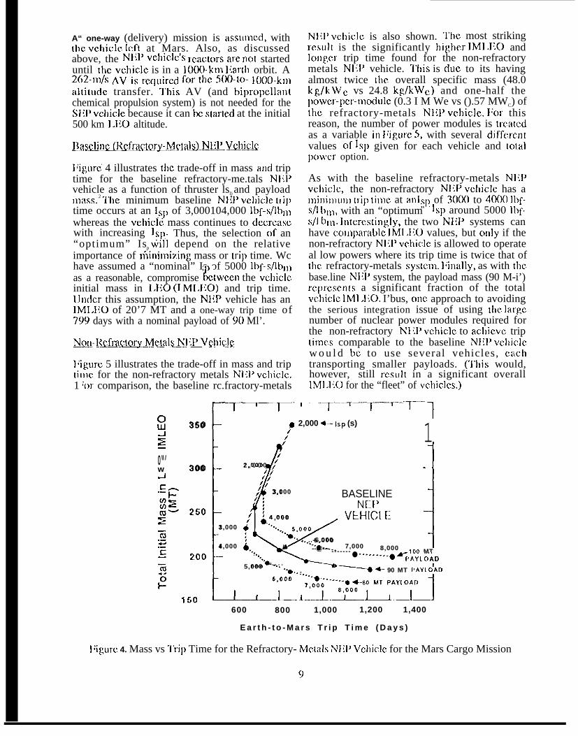
l;iguri 4 illustrates (hc trade-off in mass and triptime for the baseline refractory-me.tals N];]>vehicle as a function of thruster lsl) and payloadInass. 2 ‘1’hc minimum baseline NI:P vchiclc t[iptime occurs at an lsl) of 3,000104,000 lbf-s/lbnlwhereas the vchiclc mass continues to dccrcascwith increasing Isp. Thus, the selection of an“optimum” Isp will depend on the relativeimportance of nlininli7ting mass or trip time. Wchave assumed a “nominal” Is of 5000 lbf-s/lbll)as a reasonable, compromise ktwccn the vchiclcinitial mass in I.1~0 (I M1.IiO) and trip time.IJnder this assumption, the NH> vehicle has an1MI.I1O of 20’7 MT and a one-way trip time of799 days with a nominal payload of 90 Ml’.
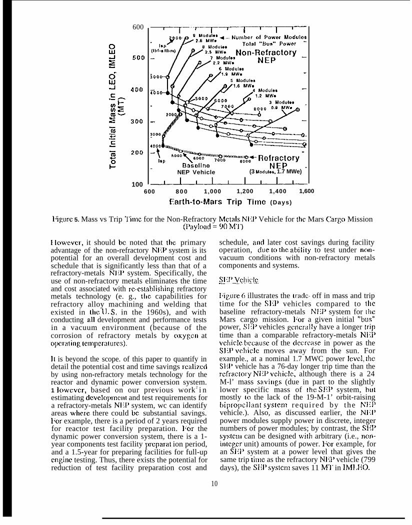
l;igurc 5 illustrates the trade-off in mass and triptime. for the non-refractory metals Nlll’ vchiclc.1 ‘or comparison, the baseline rc.fractory-metals
.[/
T_—~.
$350
/’g /’
0“’ /w 300 2 , 0 0 0 /~
J//
c- /i,//.- / 3,000
13,000
4,000
N1iI’ vchiclc is also shown. ‘1’hc most strikingIesu]t is the significantly higher IMIXO andlon:,er trip time found for the non-refractorymetals NfIP vehicle. I’his is due to its havingalmost twice the overall specific mass (48.0kg/kWe, vs 24.8 kg/kWc) and one-half thelJowcr-l~cr-l~lod~]lc (0.3 I M We vs ().57 MWC) ofthe refractory-metals NIIP vchiclc. I/or thisreason, the number of power modules is tre.atcdas a variable in l;igurc 5, with several ctiffcrentvalues of Isp given for each vehicle and totalpowm option.
As with the baseline refractory-metals NIZ1’vchiclc, the non-refractory N1lP vchiclc has an]i]]il]]l]n] trip tinlc at an ]:J) of ~ooo” to ~ooo” ]bf-s/l bIII, with an “optimum lsl) around 5000 lbf-s/l bill. lntcrcstingly, the two NIiP systems canhave coliq~arablc lMI .1;0 values, but cmly if thenon-refractory NI{P vchiclc is allowed to operateal low powers where its trip time is twice that ofthe refractory-metals systcm. l;inally, as with thebase.line Nljl’ system, the payload mass (90 M-i’)rcprcscnts a significant fraction of the totalvchiclc IMl .110. I’bus, onc approach to avoidingthe serious integration issue of using the Iargcnumber of nuclear power modules required forthe non-refractory N] W vchiclc to achicvc triptimes comparable to the baseline NIIP vchiclcw o u l d bc to use several vehicles, c~.chtransporting smaller payloads. (’1’his would,however, still rcsu]t in a significant overallIMl .110 for the “fleet” of vchiclcs.)
, . . . . ..T~T_.T~T. -T...
12,000 +—lsp (s) 1
BASELINENE:F’
, VEHIC[.E -1L;:/ :
~ 4 , 000
; a“””...
/
5,000““*..
i... ..-6.000
--@--- 7,000 8,000 i-------. . . ●
100 MT-.--. -...0 A&LolD““a . . . .5,000
““*.. - “~+- 90 MT I’AYLOAD
z ,50 t_-L---Y:_gC!zUYYl.l600 800 1,000 1,200 1,400
E a r t h - t o - M a r s T r i p T i m e ( D a y s )
l;igulc 4. Mass vs “1’rip Time for the Refractory- McIals Nllf) Vchic]c for the Mars Cargo Mission
g
600
100
~–T~~-–T-–~-r”””]--r--
NEP Vehicle (3 Modulon, 1.7 MWe)
-l__L_.l__L_L_.~600 8 0 0 1,000 1,200 1,400 1,600
~arth-lo-Mars Trip Time (Days)
l;igurc 5. Mass vs Trip ‘1’imc for the Non-Refractory Metals NIiP Vehicle for Ihe Mars cargo Mission(l%iyload = 90 M’J$)
I lowcwcr, it should be noted that the primaryadvantage of the non-refractory N];}’ system is itspotential for an overall development cost andschedule that is significantly less than that of arefractory-metals NIW system. Specifically, theuse of non-refractory metals eliminates the timeand cost associated with rc-cs[ablishing refractorymetals technology (e. g., the capabilities forrefractory alloy machining and welding thatexisted in the lJ. S, in the 1960s), and withconducting all development and performance testsin a vacuum environment (because of thecorrosion of refractory metals by oxygen atopcmting tcmpcraturcs).
II is beyond the scope. of this paper to quantify indetail the potential cost and time savings realizedby using non-refractory metals technology for thereactor and dynamic power conversion system.1 lowever, based on our previous work 2 i nestimating dcvclopmcn[ and test requirements fora refractory-metals Nlll’ system, wc can identifyareas where there could bc substantial savings.Iior example, there is a period of 2 years requiredfor reactor test facility preparation. lior thedynamic power conversion system, there is a 1-year components test facility prcparat ion period,and a 1.5-year for preparing facilities for full-upengine testing. Thus, there exists the potential forreduction of test facility preparation cost and
schedule, ancl later cost savings during facilityoperation, due tc) the abili(y to test under non-vacuum conditions with non-refractory metalscomponents and systems.
S1;1’ Vchiclc~_——
IJigure 6 illustrates the tra(ic- off in mass and triptime for the S111’ vehicles compared to [hebaseline refractory-metals NIH’ system for LhcMars cargo mission. Ikm a given initial “b~ls”power, SJ{f’ vehicles genemlly have a longer triptime than a comparable refractory-metals NI{Pvclliclc bccausc of the dccrcasc in power as theS1{1’ vchiclc moves away from the sun. Forexample., at a nominal 1.7 MWC power lCVCI, theS1:1’ vehicle has a 76-day longer trip time than thercfrac(ory NIW vchiclc, although there is a 24M-l’ mass savir~gs (due in part to the slightlylower specific mass of lhc SEP system, butmostly (o the lack of the 19-M-1’ orbit-raisingbipropc.llan{ systcrn requi red by the NIIPvehicle.). Also, as discussed earlier, the Nlll’power modules supply power in discrete, integernumbers of power modules; by contrast, the S1{1’systcmi can be designed wjth arbitrary (i.e., Jlon-intcger unit) amounts of power. I;or example, foran SIil’ system at a power level that gives thesame trip time as the refractory NIT vehicle (799days), the S111’ system saves 11 Ml’ in lMI.IX1.
10

oUJ 300-1x-.
Cj”250
-Jc:.- n~+WEm- 200z-.(u---+...-C-- 150- -(u
● Ak?
1~,fm
“o 3.4 MWO BASELINE —NEP
CASE2,9 M W e “...
/Re~Ec~ry -
For Same- “. ,. . . . . . - - - - -IMLEO: 2.3 MWe : - - - -
J
N. SEP Saves - - - - - . - e -
46 Days For Same 1.7 MWe
Trip Time: f-. ● SEP Saves SEP Po +1.1 MVI!E
1 11 MT._-.~--~.—.L-L_L..L_L.._~
6 0 0 7 0 0 8 0 0 9 0 0 1 , 0 0 0 1 , 1 0 0
Earth-to-Mars Trip Time (Days)
Figure 6. llaselinc Refractory -NljP vs S1{P for the Mars cargo Mission(Payload = 90 MT, lsp = 5000 Ibf-sflbm)
Similarly, for the same lMIXO (207 MT), theS1;1’ vehicle saves 46 days of trip time.IIowcver, there may be significant issuesassociated with packaging 2-M We worth of solararrays in a launch vehicle because additionalvolume-limited launches of solar arrays couldnegate the potential advantages of the S1iPsystem. ‘l”his issue should become less of aconcern as the emerging technologies ofconcentrator arrays and inflatable structuresJnaturc.
~Kk!.SiQIM!d!i!!Q(?JUJ-ti
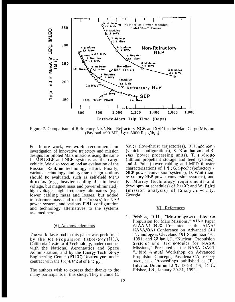
}iigure 7 summarizes the rcs.ults of the Missionanalyses for the refractory-metals NIW, non-rcfractory metals NIT, and SEP vehicles. Ilomttmsc analyses, wc scc that MWc-class SliP orrefractory-metals S1’- 100 Li-MPD NJ{]’ systemscan perform Mars cargo missicms with trip timesof two years. Ml’I) thrLJster ISPS of 4,000 to5,()(K) lbf-s/lbl and efficiencies of at least 50%
Ywill be needed.
One of the key requirements for achieving thisICVC1 of performance in the NliP vehicle is ther-c-cstablis}lment of t}~e refractory JncIal nlan-ufiicturing and welding capabilities of the 1960s,and the preparation of vacuum test fi~cilitics forrefractory-metals components and full-upsystems (both nuclear and non-nuclear). In thisstudy, we investigated the mission performanceconsequences of switching to non-refractorymetals NJW systems. We found that the NIWvehicle performance is modm atcly sensitive to
total specific mass; thus, the non-refractorymetals NI{P vehicle, with almost two times thetotal specific mass of the baseline refractory -me.tals NIIP vehicle, has a significantly lower,bu[ still acceptable, performance. Ncvcrthclcss,this lower vehicle performance may represent aftavorablc trade-off given the advantages ofavoiding the cost and delay of requiringrefractory-metals technologies.
“I”he SIT system rcprcscnts an interestingalternative to the NIW option, with the SEPvchiclc having performance comparable to that ofthe refractory-metals NIT system. There arc,however, several issues associated with the SILPsystcm that arc not encountered with the N1lPsystcJns. I“irst, there may bc difficulty associatedwith packaging MWc-class solar arrays ill alaunch vchiclc. Also, available power at Marswill be roughly half that al I;arlh; lhis may havean undcsirab]c impact on tlic attractiveness ofmaterials processing on l’hobos if that option ispul sued. ‘1’hc structures, dynamics, and controlof lar~c (37 m by 72 m) solar arrays may also bean issue. l:inally, the large area of the solar arraysmay represent a significant debris impactconcern, cspccia]l y bcca use the SI~}’ vehiclebegins its long Ilarth-cscapc spiral from arelatively debris-rich 500-kn~ I.EO. (By contrast,the NILI’ vehicles arc relatively quickly boostc{i toa 1000knl altitude by their on-board bipropcllantchemical propulsion systems.) Ilowcver, if theseconcerns can bc addressed, an SIiP vehicleremains as a viable contcndcr for Mars cargomissions.
350
o“ 300
?
~w. - 2 0 0c
IG5l-’ 150
-1-~~—-.~-~—--~-‘2 ~“~~cc ~–Nurnber of Power Modules
!’lotal “Bus”’ P o w e r
8 Modules
[
.5 MWO
7 Modules2.2 MWe
8 Modulos
4 Modules
J.O MW@ 3 Modulos
2 Modules
2.o MWR e f r a c t o r y NEP
1.5 MWOP
Total “Bus” Power
I I I I I I ..1..-1-1-.600 800 1,000 1,200 1,400 1,600 1,800
Earth-to-Mars Trip Time (Days)
Figure 7. Comparison of Refractory NEI>, Non-Refractory NIW, and SEP for the Mars Cargo Mission(Payload =90 MT, Is}) = 5000 lbf-s/Jbn~)
For future work, we would recommend aninvestigation of innovative trajectory and missiondesigns for piloted Mars missions using the same1.i-M1’D SIIP and N1iP systems as the cargovehicle. We also recommemd an evaluation of theRussian Rankine technology effort. Finally,various technology and systcn) design optionsshould bc evaluated, such as self-field Ml’]]lhrusters (e.g., heavier cabling due to lowervoltage, but magnet mass and power eliminated),high-voltage, high frequency alternators (e.g.,lower cabling mass and losses, but addedtransformer mass and rectifier 10 SSCS) for NIH’power system, and various PPU configurationand technology alternatives to the systemsassumed here.
~1, Acknowledgments
‘1’hc work dcscribcd in this paper was performedby the Jet P r o p u l s i o n I.abora[ory (JP1.),California lnstitum of ‘1’eehnology, under contractwith the National Aeronautics and SpaceAdministration, and by the Kncrgy “1’cchnologyEngineering Center (E’1’EC), Rockctdyne, undercontract with the 1 Xqmrtmcnt of Ihlergy.
The authors wish to express their thanks to themany participants in this study. They include C.
Saucr (low-thrust trajectories), R. I.indemann(vehicle configurations), S. Krauthamer and R:I)as (power processing units), T. Pivirotto(lithium propellant storage and feed systems),an(i J. Polk (power cabling and MPD thrustercharacterization) of JP1.; G. Spccht (refractory -NI;l’ power conversion systems), D. Wait (non-rcfractory NIH’ power conversion systems), andK. Murray (technology requirements anddc.vclopmcnt schedules) of 11’I’I:C; and W. Baird(miss ion analys is ) of Ilmory lJniversity,Georgia.
V]]. References
1. I~risbcc, R.II., “Multin~egawatt lllectricl’repulsion for Mars Missions,” AIAA PaperAIAA-91-3490, l’resented at the AlAA/NASA/OA1 Conference on Advanced S111‘J’echnologies, Cleveland 011, Se.ptcmbcr 4-6,1991; and Gilland, J., “Nuclear PropulsionSyStCJNS a n d ‘1’cchnologies for NASAMissions,” Presented at the NASA OACT“1’bird Annual Workshop on AdvancedPropulsion Concepts, Pasadena CA, January30-31, 1992, l%oeccdings published as JP1.lntcrnal I)ocumcnt JP1. D - 9 4 1 6 , R. Il.Frisbee, lld., January 30-31, 1992.
. ..-
2: l:risbec, R.11., and Iloffnlan, N. J., “SP-1OONuclear IHcctric Propulsion for Mars CargoMissions,” AIAA Paper AIAA 93-2092,Prcscntccl at the AIAA/SAIl/ASMl;/ASIili29th Joint Propulsion Conference, MontereyCA, JLJI~C 28 - July 1, 1993; and lirisbcc,R.]]., IIoffnlan, N. J., and Murray, K., “SP-100 IIynanlic Power and l.itl~itlt~~-I}rol~cllal~tMP1> Nuclear Iilcctric Propulsion TechnologyRequirctncnts, “ Presented at the 11th SpaceNuclear Power and Propulsion Synlposiutn,Albuquerque NM, January 9-13, 1994.
3. }Jrisbee, R.]]., Ilas, R . S . I . . , a n dKrauthanm, S., “Power Processing Unitsf o r }ligh Powered Nuclear l;lectricPropulsion with MM] ‘1’hrusters,” Presentedat the AIAA/llGI.R/AIIIAA/J SASS 23rdinternational l{lectric Propulsion Conference,Seattle WA, Septetnber 13-16, 1993.
4. Krauthanwr, S., et al., “Power ProcessingUnits for IIigh Powered Solar ElectricPropuls ion Using MP1) Thrust ers,”Presented at the 28th IIiCllC, Atlanta GA,August 8-13, 1993.
S. Gilland, J., and George, J., “’l~arly Track’NH’ Sys[em Options for SE] Missions,”AIAA Paper AIAA 92-3200, Presented at theAIAA/SAIVASMIi/A SIlll 2 8 t h J o i n tPropulsion Conference, Nashville ‘l’N, JLlly6-8, 1992.
13