Embed Size (px)
Citation preview

1American Institute of Aeronautics and Astronautics
CLIMB TRAJECTORY PREDICTION ENHANCEMENT USINGAIRLINE FLIGHT-PLANNING INFORMATION
Richard A. Coppenbarger *
NASA Ames Research CenterMoffett Field, CA
Abstract
Software decision support tools that assist controllerswith the management of air traffic are dependent uponthe ability to accurately predict future aircraft positions.Trajectory predictions in en route airspace rely upon theavailability of aircraft state, aircraft performance, pilotintent, and atmospheric data. The use of real-time airlineinformation for improving ground-based trajectorypredictions has been a recent focus in the developmentof the Center-TRACON Automation System (CTAS) atNASA Ames. This paper studies the impact of airlineflight-planning data on CTAS en route climb trajectoryprediction accuracy. The climb trajectory synthesisprocess is first described along with existing input data.Flight–planning data parameters, available from atypical airline operations center, are then discussedalong with their potential usefulness to CTAS. Resultsare then presented to show the significant impact ofairline-provided takeoff weight, speed-profile, and thrustcalibration data on CTAS climb trajectory predictionperformance.
Introduction
In order to assist with Air-Traffic Management (ATM)under capacity-constrained conditions, the Center-TRACON Automation System (CTAS) has beendeveloped at NASA Ames Research Center. CTASincludes a collection of software decision-support toolsthat enhance situational awareness and provide clearanceadvisories to assist controllers in separating, scheduling,sequencing, and spacing aircraft in en route and terminalairspace.
The en route CTAS tools, which have been evaluated inthe field, include the Traffic Management Advisor(TMA), the En route Descent Advisor (EDA), andConflict Prediction and Trial Planner (CPTP). TMAgenerates schedules and sequences for aircrafttransitioning from en route to terminal airspace, subjectto airport capacity constraints. EDA assists controllersin developing efficient, conflict-free, descent advisoriesto deliver aircraft to the Center-TRACON boundary inaccordance with TMA schedules1. CPTP assists withthe identification and resolution of conflicts for allaircraft, whether in climb, cruise, or descent2.
Together, the CTAS tools are designed to maximizeairspace and airport capacity while improving theoverall efficiency of flight operations. A centralcapability of CTAS, which provides the foundation forall CTAS tools, is the ability to accurately predict thefuture spatial and temporal position of each aircraft inthe airspace over a range of look-ahead times. Thiscapability is provided by the Trajectory Synthesizer(TS) module, often referred to as the CTAS“computational engine”3.
The accuracy of trajectory predictions in en route(Center) airspace impacts ATM conflict predictions andEstimated Times of Arrival (ETAs) to control fixes4.Preliminary studies have shown that trajectoryuncertainties can significantly effect the schedules andmaneuver advisories that CTAS generates to managetraffic flows and resolve separation conflicts5. For theairspace user, inaccurate trajectory predictions mayresult in less-than-optimal maneuver advisories inresponse to a given traffic management problem. Theseinclude missed advisories and false advisories. Missedadvisories refer to the lost opportunity of resolving atraffic management problem in a manner most efficientto the airspace user. An example of a missed advisory isthe failure to resolve a conflict between two aircraft atthe earliest opportunity, requiring the least amount offuel-burn between them. False advisories refer to thesuggestion of an unnecessary maneuver that may causean aircraft to depart from its most efficient, or user-preferred, trajectory. An example of a false advisoryoccurs when an aircraft is vectored unnecessarily off its
*Research Engineer, Member AIAA
Copyright 1999 by the American Institute ofAeronautics and Astronautics, Inc. No copyright isasserted in the United States under Title 17, U.S. Code.The U.S. Government has a royalty-free license toexercise all rights under the copyright claimed hereinfor Governmental Purposes. All other rights arereserved by the copyright owner.
AIAA-99-4147
2American Institute of Aeronautics and Astronautics
filed or preferred flight path in response to a falseconflict alert. Although false and missed advisories canresult in lost efficiency to user operations, they do notcompromise safety. This is because ATM decisionsupport tools involve long-range strategic trajectorypredictions that are frequently updated and used by theservice provider to continually reassess the trafficsituation. Traffic management problems that are notresolved at the earliest, or most desirable, time can beexpected to be resolved at a future time, but at theexpense of user efficiency and controller workload. Inaddition to limiting user and ATM efficiency, inaccuratetrajectory predictions also waste airspace capacity byforcing the controller to apply larger than requiredseparation buffers in response to position uncertainties.
A limiting factor in the accurate prediction of aircrafttrajectories is the difficulty in obtaining precisetrajectory calibration and intent data for individualflights. Trajectory calibration data refers to aircraft state,aircraft performance, and atmospheric characteristics thatinfluence the external forces acting on the aircraft.Trajectory intent information includes the anticipatedroute, speed profile, and maneuvering procedure of theaircraft over the trajectory prediction time horizon. Thepilot, in concurrence with ATM clearance instructions,ultimately establishes the trajectory intent of a givenflight.
The En route Data Exchange (EDX) research program atNASA Ames is addressing the exchange of trajectoryinformation between the airspace user and the air trafficcontrol system. The initial objective of EDX is toimprove CTAS en route trajectory predictions byobtaining timely calibration and intent data from usersystems. In an operational environment, userinformation can be acquired from either ground-based orairborne sources. Ground-based sources, which canreadily provide pre-departure flight-planning data,include Airline Operational Control (AOC) centers andFlight Service Stations. Airborne data sources includethe Flight Management System (FMS) and otheravionics systems that can provide post-departure datathrough air-ground data link. In the interest ofexploiting currently available technology andminimizing cost, EDX will consider obtainingtrajectory data from ground-based resources, prior tofocusing on aircraft systems and data link capabilities.
This paper describes an initial EDX study to investigatethe potential improvement that AOC flight-planninginformation offers to CTAS climb trajectorypredictions. In support of current CTAS en route tools,accurate climb predictions are necessary in order to
probe for conflicts and issue direct-route clearances thatenhance user efficiency by shortening flight time. Thealgorithms and input data used in the current climbtrajectory prediction process are first described, followedby a description of pertinent data elements that are eitheravailable or derivable from AOC flight-planningresources. Results are then presented which show theoperational range of AOC trajectory parameters and theirimpact on the accuracy of CTAS climb predictions.
TS Algorithms and Existing Input Data
The CTAS TS uses a simplified set of point-massaircraft equations of motion for generating four-dimensional (4D) trajectories consisting of aircraftposition (x-y) and altitude over range of future times. InCenter airspace, new predicted trajectories are generatedfor all aircraft in the airspace following each completeradar sweep (12 seconds). Trajectories are generated byintegrating between predefined waypoints, defined by thecurrent aircraft position, filed flight plan route, andairspace description data. The simplified equations ofmotion used by the TS, described fully in Reference 6,are given by
dh / dt = a VT = i VG (1)
VG = UW cos ( G - W ) + (2)
V T cos ( sin -1 ( UW sin ( G - W ) / VT ) )
dVT / dt = (T - D )/ m - g a − g i VT dUW / dt (3)
where h is geometric altitude; m is the aircraft mass; gis acceleration due to gravity; UW is wind speed; VG isground speed; V T is true airspeed; W and G are the winddirection and ground speed direction, respectively; a and
i are the aerodynamic and inertial flight path angles,respectively; T is the aircraft thrust; and D and is theaircraft drag.
To simplify the prediction process, the horizontal andvertical components of the trajectory are de-coupled.First, an approximate vertical profile is computed inorder to compute true airspeed as a function of pathdistance. This approximate speed profile is then used tocalculate turn radii used in the synthesis of thehorizontal trajectory, consisting of a series of straight-line segments connected by constant radius turns. Thishorizontal trajectory is then used as the basis forcomputing the actual vertical profile.
3American Institute of Aeronautics and Astronautics
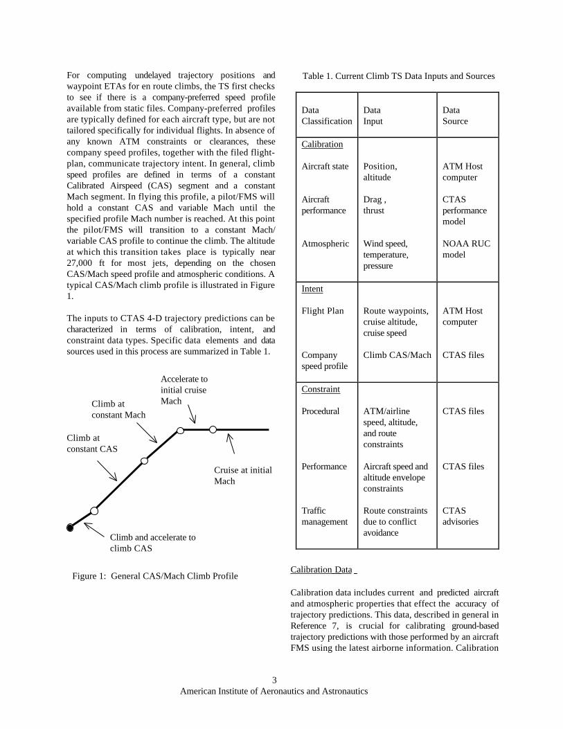
For computing undelayed trajectory positions andwaypoint ETAs for en route climbs, the TS first checksto see if there is a company-preferred speed profileavailable from static files. Company-preferred profilesare typically defined for each aircraft type, but are nottailored specifically for individual flights. In absence ofany known ATM constraints or clearances, thesecompany speed profiles, together with the filed flight-plan, communicate trajectory intent. In general, climbspeed profiles are defined in terms of a constantCalibrated Airspeed (CAS) segment and a constantMach segment. In flying this profile, a pilot/FMS willhold a constant CAS and variable Mach until thespecified profile Mach number is reached. At this pointthe pilot/FMS will transition to a constant Mach/variable CAS profile to continue the climb. The altitudeat which this transition takes place is typically near27,000 ft for most jets, depending on the chosenCAS/Mach speed profile and atmospheric conditions. Atypical CAS/Mach climb profile is illustrated in Figure1.
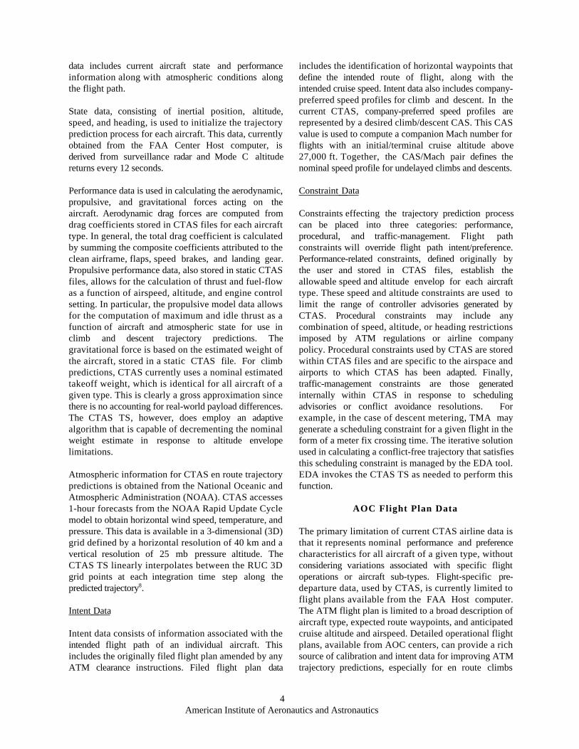
The inputs to CTAS 4-D trajectory predictions can becharacterized in terms of calibration, intent, andconstraint data types. Specific data elements and datasources used in this process are summarized in Table 1.
Calibration Data
Calibration data includes current and predicted aircraftand atmospheric properties that effect the accuracy oftrajectory predictions. This data, described in general inReference 7, is crucial for calibrating ground-basedtrajectory predictions with those performed by an aircraftFMS using the latest airborne information. Calibration
Figure 1: General CAS/Mach Climb Profile
Climb and accelerate toclimb CAS
Climb atconstant CAS
Climb atconstant Mach
Accelerate toinitial cruiseMach
Cruise at initialMach
Table 1. Current Climb TS Data Inputs and Sources
DataClassification
DataInput
DataSource
Calibration
Aircraft state
Aircraftperformance
Atmospheric
Position,altitude
Drag ,thrust
Wind speed,temperature,pressure
ATM Hostcomputer
CTASperformancemodel
NOAA RUCmodel
Intent
Flight Plan
Companyspeed profile
Route waypoints,cruise altitude,cruise speed
Climb CAS/Mach
ATM Hostcomputer
CTAS files
Constraint
Procedural
Performance
Trafficmanagement
ATM/airlinespeed, altitude,and routeconstraints
Aircraft speed andaltitude envelopeconstraints
Route constraintsdue to conflictavoidance
CTAS files
CTAS files
CTASadvisories
4American Institute of Aeronautics and Astronautics
data includes current aircraft state and performanceinformation along with atmospheric conditions alongthe flight path.
State data, consisting of inertial position, altitude,speed, and heading, is used to initialize the trajectoryprediction process for each aircraft. This data, currentlyobtained from the FAA Center Host computer, isderived from surveillance radar and Mode C altitudereturns every 12 seconds.
Performance data is used in calculating the aerodynamic,propulsive, and gravitational forces acting on theaircraft. Aerodynamic drag forces are computed fromdrag coefficients stored in CTAS files for each aircrafttype. In general, the total drag coefficient is calculatedby summing the composite coefficients attributed to theclean airframe, flaps, speed brakes, and landing gear.Propulsive performance data, also stored in static CTASfiles, allows for the calculation of thrust and fuel-flowas a function of airspeed, altitude, and engine controlsetting. In particular, the propulsive model data allowsfor the computation of maximum and idle thrust as afunction of aircraft and atmospheric state for use inclimb and descent trajectory predictions. Thegravitational force is based on the estimated weight ofthe aircraft, stored in a static CTAS file. For climbpredictions, CTAS currently uses a nominal estimatedtakeoff weight, which is identical for all aircraft of agiven type. This is clearly a gross approximation sincethere is no accounting for real-world payload differences.The CTAS TS, however, does employ an adaptivealgorithm that is capable of decrementing the nominalweight estimate in response to altitude envelopelimitations.
Atmospheric information for CTAS en route trajectorypredictions is obtained from the National Oceanic andAtmospheric Administration (NOAA). CTAS accesses1-hour forecasts from the NOAA Rapid Update Cyclemodel to obtain horizontal wind speed, temperature, andpressure. This data is available in a 3-dimensional (3D)grid defined by a horizontal resolution of 40 km and avertical resolution of 25 mb pressure altitude. TheCTAS TS linearly interpolates between the RUC 3Dgrid points at each integration time step along thepredicted trajectory8.
Intent Data
Intent data consists of information associated with theintended flight path of an individual aircraft. Thisincludes the originally filed flight plan amended by anyATM clearance instructions. Filed flight plan data
includes the identification of horizontal waypoints thatdefine the intended route of flight, along with theintended cruise speed. Intent data also includes company-preferred speed profiles for climb and descent. In thecurrent CTAS, company-preferred speed profiles arerepresented by a desired climb/descent CAS. This CASvalue is used to compute a companion Mach number forflights with an initial/terminal cruise altitude above27,000 ft. Together, the CAS/Mach pair defines thenominal speed profile for undelayed climbs and descents.
Constraint Data
Constraints effecting the trajectory prediction processcan be placed into three categories: performance,procedural, and traffic-management. Flight pathconstraints will override flight path intent/preference.Performance-related constraints, defined originally bythe user and stored in CTAS files, establish theallowable speed and altitude envelop for each aircrafttype. These speed and altitude constraints are used tolimit the range of controller advisories generated byCTAS. Procedural constraints may include anycombination of speed, altitude, or heading restrictionsimposed by ATM regulations or airline companypolicy. Procedural constraints used by CTAS are storedwithin CTAS files and are specific to the airspace andairports to which CTAS has been adapted. Finally,traffic-management constraints are those generatedinternally within CTAS in response to schedulingadvisories or conflict avoidance resolutions. Forexample, in the case of descent metering, TMA maygenerate a scheduling constraint for a given flight in theform of a meter fix crossing time. The iterative solutionused in calculating a conflict-free trajectory that satisfiesthis scheduling constraint is managed by the EDA tool.EDA invokes the CTAS TS as needed to perform thisfunction.
AOC Flight Plan Data
The primary limitation of current CTAS airline data isthat it represents nominal performance and preferencecharacteristics for all aircraft of a given type, withoutconsidering variations associated with specific flightoperations or aircraft sub-types. Flight-specific pre-departure data, used by CTAS, is currently limited toflight plans available from the FAA Host computer.The ATM flight plan is limited to a broad description ofaircraft type, expected route waypoints, and anticipatedcruise altitude and airspeed. Detailed operational flightplans, available from AOC centers, can provide a richsource of calibration and intent data for improving ATMtrajectory predictions, especially for en route climbs
5American Institute of Aeronautics and Astronautics
(above 10,000 ft). This data includes such items asaircraft weight, thrust and drag performance factors, andspeed profile intent.
In addition to improving the accuracy of ground-basedpredictions, the receipt of AOC flight-planning data canallow the air traffic system to be more responsive toairline operational preferences. Pre-departure intent dataprovided by the AOC represents the preferred speed androuting for an individual flight, in absence of anyunknown ATM, weather, or airspace restrictions.Airline trajectory preferences may be tailored to the fuelperformance of an individual flight, or to the overallschedule efficiency of the airline as a whole. With betterknowledge of the trajectory preferences associated withindividual flights, ATM automation can moreeffectively accommodate airline operationalconsiderations into traffic management advisories.
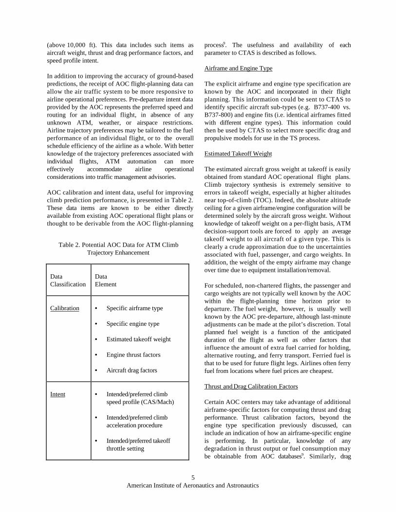
AOC calibration and intent data, useful for improvingclimb prediction performance, is presented in Table 2.These data items are known to be either directlyavailable from existing AOC operational flight plans orthought to be derivable from the AOC flight-planning
process9. The usefulness and availability of eachparameter to CTAS is described as follows.
Airframe and Engine Type
The explicit airframe and engine type specification areknown by the AOC and incorporated in their flightplanning. This information could be sent to CTAS toidentify specific aircraft sub-types (e.g. B737-400 vs.B737-800) and engine fits (i.e. identical airframes fittedwith different engine types). This information couldthen be used by CTAS to select more specific drag andpropulsive models for use in the TS process.
Estimated Takeoff Weight
The estimated aircraft gross weight at takeoff is easilyobtained from standard AOC operational flight plans.Climb trajectory synthesis is extremely sensitive toerrors in takeoff weight, especially at higher altitudesnear top-of-climb (TOC). Indeed, the absolute altitudeceiling for a given airframe/engine configuration will bedetermined solely by the aircraft gross weight. Withoutknowledge of takeoff weight on a per-flight basis, ATMdecision-support tools are forced to apply an averagetakeoff weight to all aircraft of a given type. This isclearly a crude approximation due to the uncertaintiesassociated with fuel, passenger, and cargo weights. Inaddition, the weight of the empty airframe may changeover time due to equipment installation/removal.
For scheduled, non-chartered flights, the passenger andcargo weights are not typically well known by the AOCwithin the flight-planning time horizon prior todeparture. The fuel weight, however, is usually wellknown by the AOC pre-departure, although last-minuteadjustments can be made at the pilot’s discretion. Totalplanned fuel weight is a function of the anticipatedduration of the flight as well as other factors thatinfluence the amount of extra fuel carried for holding,alternative routing, and ferry transport. Ferried fuel isthat to be used for future flight legs. Airlines often ferryfuel from locations where fuel prices are cheapest.
Thrust and Drag Calibration Factors
Certain AOC centers may take advantage of additionalairframe-specific factors for computing thrust and dragperformance. Thrust calibration factors, beyond theengine type specification previously discussed, caninclude an indication of how an airframe-specific engineis performing. In particular, knowledge of anydegradation in thrust output or fuel consumption maybe obtainable from AOC databases9. Similarly, drag
Table 2. Potential AOC Data for ATM ClimbTrajectory Enhancement
DataClassification
DataElement
Calibration • Specific airframe type
• Specific engine type
• Estimated takeoff weight • Engine thrust factors • Aircraft drag factors
Intent • Intended/preferred climbspeed profile (CAS/Mach)
• Intended/preferred climbacceleration procedure
• Intended/preferred takeoffthrottle setting
6American Institute of Aeronautics and Astronautics
Table 3. Observed Variation in Takeoff Weight AmongCommon Aircraft Types
Aircrafttype
Meanweight(1b)
Std.dev.(% ofmean)
Min.weight(% frommean)
Max.weight(% frommean)
B727 159,700 6.8 -22.9 +14.3
B737 118,500 4.5 -8.8 +9.6
B747 567,700 3.9 -4.0 +6.8
B757 192,500 6.4 -23.8 +37.2
B767 341,800 15.0 -26.8 +19.3
B777 424,400 5.2 -9.3 +8.6
DC10 448,100 20.1 -29.3 +36.6
A319 126,000 6.5 -11.4 +15.1
F100 87,400 5.8 -20.6 +34.4
MD11 416,500 3.4 -3.5 +3.1
MD80 129,900 7.1 -27.0 +51.6
performance factors may include any known changes inthe drag characteristics associated with an individualairframe. It is likely that AOC centers will haveknowledge of these characteristics from their analysis ofin-flight performance data10.
Climb Speed Profile
Climb speed profile, as described in the previoussection, is fundamental to ATM climb trajectorypredictions in en route airspace. In the current CTASmodel, this parameter does not account for operationalvariations among individual flights. Although the pilothas the final authority in determining which CAS/Machspeed profile is flown, the AOC could provide arecommendation based upon operational considerations.For example, the importance of making up for lost timedue a schedule slip will influence the decision to choosea profile that maximizes climb rate as opposed tomaximizing fuel efficiency. For FMS-equipped flights,this recommendation is commonly issued by the AOCin the form of a cost index for climb powermanagement.
Climb Throttle Setting and Acceleration Procedure
Climb throttle setting is a variable that determinesaircraft thrust and is set at the discretion of the pilot incompliance with company procedures. For example,many airlines recommend reduced takeoff and climbthrust settings, when feasible, in order to prolongengine life and reduce maintenance costs. Other climbprocedure data, potentially available from the AOC,includes the preferred procedure for accelerating from theTRACON speed, below 10,000 ft, to the initial enroute climb speed, above 10,000 ft. The pilot maychoose to perform this acceleration in level flight orduring the climb, depending on operational objectives. Although secondary in importance to speed profile,these additional intent parameters, if well established bythe AOC, could be sent to ATM to further improveclimb prediction accuracy.
Results
The following results indicate the potentialimprovement that AOC flight-planning data has onCTAS climb trajectory predictions. In particular, theactual or anticipated impact of AOC takeoff weight,speed profile, and thrust calibration data on CTAStrajectory synthesis is examined.
Weight
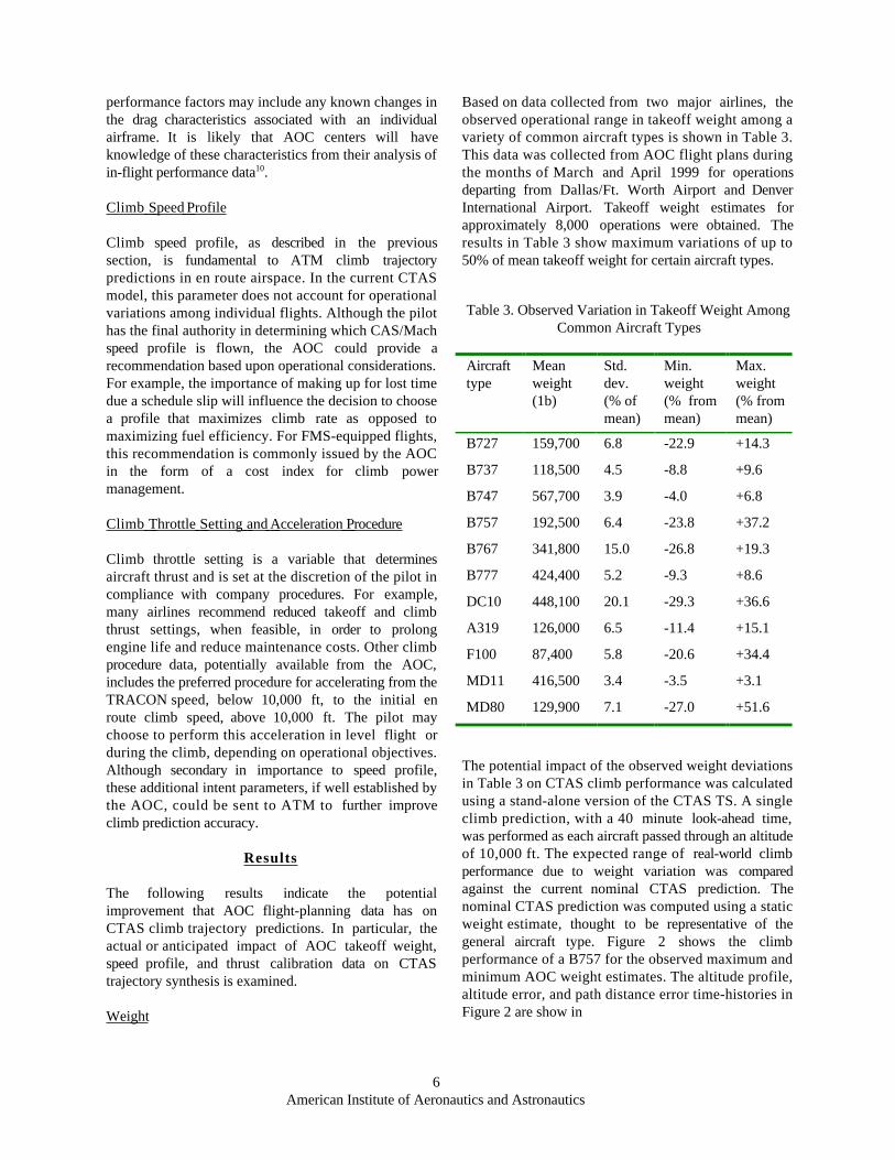
Based on data collected from two major airlines, theobserved operational range in takeoff weight among avariety of common aircraft types is shown in Table 3.This data was collected from AOC flight plans duringthe months of March and April 1999 for operationsdeparting from Dallas/Ft. Worth Airport and DenverInternational Airport. Takeoff weight estimates forapproximately 8,000 operations were obtained. Theresults in Table 3 show maximum variations of up to50% of mean takeoff weight for certain aircraft types.
The potential impact of the observed weight deviationsin Table 3 on CTAS climb performance was calculatedusing a stand-alone version of the CTAS TS. A singleclimb prediction, with a 40 minute look-ahead time,was performed as each aircraft passed through an altitudeof 10,000 ft. The expected range of real-world climbperformance due to weight variation was comparedagainst the current nominal CTAS prediction. Thenominal CTAS prediction was computed using a staticweight estimate, thought to be representative of thegeneral aircraft type. Figure 2 shows the climbperformance of a B757 for the observed maximum andminimum AOC weight estimates. The altitude profile,altitude error, and path distance error time-histories inFigure 2 are show in

7American Institute of Aeronautics and Astronautics
comparison with the nominal CTAS trajectory, using
the generalized weight estimate.
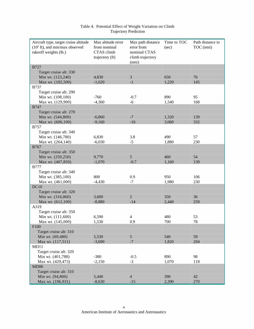
Table 4 summarizes the effect of observed takeoffweight variation on climb performance among theaircraft types for which data was obtained from the AOCcenters. In Table 4, the metrics chosen to representclimb performance in comparison with nominal CTAStrajectories are: 1) maximum altitude error over theprediction time horizon, 2) maximum longitudinal pathdistance error over the prediction time horizon, 3) timerequired to reach TOC, and 4) longitudinal path distancerequired to reach TOC. The purpose of Table 4 is toshow “worst case” scenarios, not typical CTAS errors,in comparing trajectory predictions with and withoutAOC data exchange. For this purpose, the extrememinimum and maximum weight observations from theAOC data were used. In generating Table 4, terminalaltitudes were chosen as representative operational cruisealtitudes for each aircraft type. In the event that thecruise altitude was beyond the operational ceiling for theheaviest aircraft using the current CTAS performancemodel, the target altitude was lowered accordingly. Itshould be noted that in the case of the B737, B747, andA319 aircraft types, the CTAS nominal weightestimates did not fall within the range of operationalweight estimates obtained from AOC data over therecording period. This indicates the existence of obviousmodeling inaccuracies that could be corrected with thedata from this experiment.
The results in Table 4 show significant potential errorsin CTAS climb predictions due to observed variationsin takeoff weight. Potential peak altitude errors ofnearly 10,000 ft are shown for the B747 and B767aircraft. Peak longitudinal errors in the climb of 15nmi. or more are shown for the B747, DC10, andMD80 aircraft. Table 4 also indicates a dramaticpotential variation in time and distance to TOC forthese aircraft types – up to 35 minutes and 230 nmi.
In order to show improvement in climb trajectoryprediction accuracy with the inclusion of AOC weightestimates, predicted climb profiles were comparedagainst actual radar track data. This was accomplishedby extracting radar track data from CTAS archives andmatching it with flights for which AOC takeoff weightdata was obtained. In order to make the trajectorypredictions valid, wind and temperature data files,relevant to the flights of interest, were also retrievedfrom CTAS archives. Finally, care was taken to ensurethat flights selected for this analysis did not get their
Time (sec)
Alti
tude
(ft
)A
ltitu
de e
rror
(ft
)Pa
th d
ista
nce
erro
r (n
mi)
Figure 2: Potential Impact of Observed WeightVariation on B757 Climb Trajectory Synthesis
CTAS nominal wt.
AOC-observed min. wt.
AOC-observed max. wt.
8American Institute of Aeronautics and Astronautics
Table 4. Potential Effect of Weight Variation on ClimbTrajectory Prediction
Aircraft type, target cruise altitude(102 ft), and min/max observedtakeoff weights (lb.)
Max altitude errorfrom nominalCTAS climbtrajectory (ft)
Max path distanceerror fromnominal CTASclimb trajectory(nmi)
Time to TOC(sec)
Path distance toTOC (nmi)
B727 Target cruise alt: 330 Min wt. (123,240) Max wt. (182,500)
4,830-1,620
3-1
6501,220
76145
B737 Target cruise alt: 290 Min wt. (108,100) Max wt. (129,900)
-760-4,360
-0.7-6
8901,540
95168
B747 Target cruise alt: 270 Min wt. (544,800) Max wt. (606,100)
-6,860-9,160
-7-16
1,3203,060
139332
B757 Target cruise alt: 340 Min wt. (146,780) Max wt. (264,140)
6,830-6,030
3.8-5
4901,880
57230
B767 Target cruise alt: 350 Min wt. (250,250) Max wt. (407,850)
9,770-1,070
5-0.7
4601,160
54139
B777 Target cruise alt: 340 Min wt. (385,100) Max wt. (461,000)
800-4,430
0.9-7
9501,980
106230
DC10 Target cruise alt: 320 Min wt. (316,860) Max wt. (612,100)
3,600-8,880
2-14
3502,440
36259
A319 Target cruise alt: 350 Min wt. (111,600) Max wt. (145,000)
6,5901,530
40.9
480700
5378
F100 Target cruise alt: 310 Min wt. (69,480) Max wt. (117,511)
5,530-3,690
5-7
5401,820
59204
MD11 Target cruise alt: 320 Min wt. (401,788) Max wt. (429,473)
-380-2,150
-0.5-3
8901,070
98118
MD80 Target cruise alt: 310 Min wt. (94,800) Max wt. (196,931)
5,440-8,630
4-15
3902,390
42270

9American Institute of Aeronautics and Astronautics
climb profiles interrupted in any way by unexpectedATM clearance instructions. Figure 3 shows anexample of corroborated climb trajectory enhancementwith AOC weight data, for specific flights of a B757and MD80.
Although most of the TS predictions showedimprovements similar to those in Figure 3, a fewpredictions proved to be less accurate with the inclusionof AOC weight estimates. This is likely due toinaccuracies in current CTAS engine models. Thispoints to an important requirement of matching accurateweight estimates with more precise aircraft thrustperformance modeling.
Speed Profile
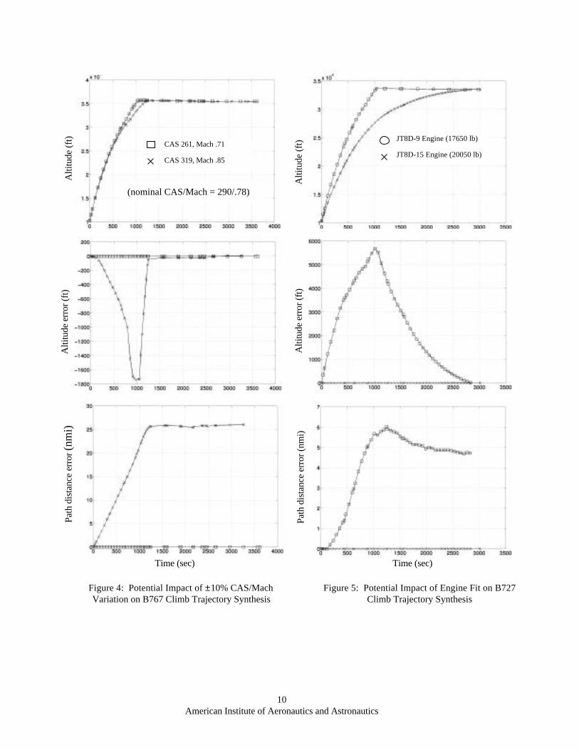
In order to show the impact of speed-profile variation onCTAS trajectory synthesis, climb profiles are shown inFigure 4 for a ±10% variation in CAS/Mach. This off-nominal value was chosen only to show TS sensitivityto speed profile error. A more precise measurement ofactual speed-profile variation for real-world operationsremains a subject for further study.
The altitude and path distance error profiles in Figure 4shows peak errors of 2,700 ft and 25 nmi, over theduration of the climb. This shows that longitudinalerror is highly sensitive and grows with time due toCAS/Mach variation. This analysis points to theimportance of obtaining flight-specific
Radar truth
Prediction with nominal weight
Prediction with AOC weight
Alti
tude
(ft
)
Time (sec) Time (sec)
Path
dis
tanc
e (n
mi)
Figure 3: Example of Improvement in CTAS Climb Predictionwith AOC Weight Estimate for B757 and MD80
a) B757 b) MD80
itude
(ft)
10American Institute of Aeronautics and Astronautics
CAS 261, Mach .71
CAS 319, Mach .85
Alti
tude
(ft
)A
ltitu
de e
rror
(ft
)Pa
th d
ista
nce
erro
r (n
mi)
Figure 4: Potential Impact of ±10% CAS/MachVariation on B767 Climb Trajectory Synthesis
Time (sec)
(nominal CAS/Mach = 290/.78)
Alti
tude
(ft
)A
ltitu
de e
rror
(ft
)Pa
th d
ista
nce
erro
r (n
mi)
Time (sec)
JT8D-9 Engine (17650 lb)
JT8D-15 Engine (20050 lb)
Figure 5: Potential Impact of Engine Fit on B727Climb Trajectory Synthesis

11American Institute of Aeronautics and Astronautics
CAS/Mach speed profiles from the AOC or aircraftsystems in order to significantly improve ATM climbprediction accuracy.
Climb Thrust
The potential influence of engine fit on ATM climbprediction is shown in Figure 5, based upon an AOC-reported average climb thrust variation of approximately12% for two different engine types for the B727. Theresults in Figure 5 were generated for identical weightsand climb speed profiles. The altitude and path distanceerror profiles show peak errors of 5,700 ft and 6 nmi,respectively, for a 12% variation in climb thrust
Conclusion
The CTAS climb trajectory prediction process has beendescribed along with current input data for establishingtrajectory calibration and pilot intent. Current input datahas been shown to be broadly defined for generic aircrafttypes and nominal airline preference, without takinginto account the operational considerations of specificflights or performance variations among individualaircraft of a given type. Flight-planning data from AOCcenters offers substantial improvement in en routeclimb prediction accuracy, promising capacity andefficiency benefits for the airspace user. In particular,AOC-provided takeoff weight, speed profile, and enginetype specification can significantly reduce climbtrajectory uncertainty. Although the results of thisanalysis indicate dramatic potential benefits of includingAOC performance and intent data in the ATM trajectoryprediction process, aircraft performance models must beof sufficient fidelity in order to appropriately benefitfrom airline information.
Acknowledgements
The work by Rey Salcido, of Ratheon STX Co., inproviding the software engineering and data analysissupport for this work is greatly appreciated. Thanks isalso given to Steve Green and Gerd Kanning, of NASAAmes Research Center, for their contributions to thiseffort.
References
[1] Denery, Dallas G., Erzberger, Heinz, “The Center-TRACON Automation System: Simulation andField Testing,” NASA Technical Memorandum110366, August 1995.
[2] McNally, B.D., Bach, R.E., “Field Evaluation ofthe CTAS Conflict Prediction and Trial PlanningCapability,” Proceedings of the 1998 Guidance,Navigation, and Control Conference, Paper No.4480, Boston, MA, August 1998.
[3] Computer Sciences Corporation (CSC), “Center-TRACON Automation System (CTAS) TrajectorySynthesizer (TS) Functional Description/ Top-Level Design,” prepared for Federal AviationAdministration, Contract No. DTFA01-95-C-00037, October 1998.
[4] Wanke, Craig, “Using Air-ground Data Link andOperator-Provided Planning Data to Improve ATMDecision Support System Performance,”Proceedings of the 1997 Digital Avionics SystemsConference (DASC), October 1997.
[5] Green, S.M., and Vivona, R., “Field Evaluation ofDescent Advisor Trajectory Prediction Accuracy,”Proceedings of the AIAA Conference on Guidance,Navigation, and Control, San Diego, CA, July1996.
[6] Slattery, R. A., Zhao, Y., “En route DescentTrajectory Synthesis for Air Traffic ControlAutomation,” Proceedings of the American ControlConference, Seattle, WA, June 1995.
[7] Green, S.M., Goka, T., Williams, D.H., “EnablingUser Preferences Through Data Exchange,”Proceedings of the AIAA Conference on Guidance,Navigation, and Control, New Orleans, LA,August 1996.
[8] Benjamin, S.G., Brundage, K. J., and Morone,L.L., “The Rapid Update Cycle. Part I: AnalysisModel Description,” Technical Procedures BulletinNo. 416, NOAA/NWS, 1994.
[9] EUROCONTROL Experimental Center, “Study ofthe Acquisition of Data from Aircraft Operators toAid Trajectory Prediction Calculation,” EEC NoteNo. 18/98, September 1998.
[10] FM-ATM Next Generation (FANG) Matrix Team,“Airline Operational Control Overview,”DOT/FAA/AND-98/8, July 1997.