Embed Size (px)
Citation preview
AIAA JOURNAL Vol. 54, No. 3, March 2016: Author’s post-print version (final draft post-refereeing)
Simplified model for flow-heating effect on wave drag
and its validation
Erich Schulein∗
German Aerospace Center DLR,
Institute of Aerodynamics and Flow Technology,
D-37073 Gottingen, Germany
Simplified prediction method for determination of flow-heating effects on the wave dragof bodies based on the combined analytical-empirical model of the thermal-spike phe-nomenon is presented. The existing model conceptions addressing certain aspects of thisphenomenon were complemented and refined to develop a method suitable for parameterstudies. Some reliable experimental and numerical results for the Mach 3 supersonic flowover conically nosed bodies were used as training data to estimate empirically the modelparameters. Finally, the method was cross-validated by the different available results forblunt bodies with hemispherical, flat and conical front faces. By this opportunity the abilityto predict the influence of some crucial parameters has successfully been demonstrated forthe heat input ratio at steady and periodic heating, the normalized heated-wake/filamentdiameter, the Mach number and the specific heat capacity.
Nomenclature
A,B,C empirical parameterscd forebody drag coefficientcdf forebody drag coefficient based on absolute pressurecp specific heat at constant pressured streamtube diameterdq heating source diameter (dq = d1)Dmod model diameterq specific heat powerKpres pressure level ratio induced by the unheated flowKsep normalized cross-sectional area covered by the recirulation bubbleM Mach numberp static pressurepheat heating powerp0 total pressurep′0 Pitot pressureR radiusReD Reynolds number based on model diameters streamwise coordinate along the model surfaceS cross-sectional areatfil traveling time of the heated filamenttperiod period time at periodic heatingT absolute temperatureT0 total temperatureU velocityx longitudinal coordinate
∗Research Scientist, High Speed Configurations Department, [email protected], Senior Member AIAA
1 of 15
American Institute of Aeronautics and Astronautics
δ boundary layer thicknessη drag reduction efficiency η = (cd0 − cd) 0.5 ρ1U
21 Smod U1/pheat
ε heat input ratio ε = q/(cpT1)ε0 energy input ratio ε0 = q/(cpT0)γ heat capacity ratioθ cone half angleω gas rarefaction degree ω = ρ3/ρ1
ρ density
Subscript∞ free-stream flow conditions0 total flow conditions, conditions without flow heating1 flow conditions upstream of the shock wave (zone 1)2 flow conditions behind the bow shock wave (zone 2)3 flow conditions behind the heating source (zone 3)5 flow conditions at the reattachment region (zone 5)c conditions at the conefil parameters of the high-temperature filamentq conditions at the heating sourcemax conditions at the efficiency maximummaxd conditions at the maximum deflection anglemod model parameterssep recirculation (”separation”) bubble parametersw wall conditionswh wall conditions at flow heatingwo wall conditions without flow heatingx based on the longitudinal coordinateδ based on boundary layer thickness
I. Introduction
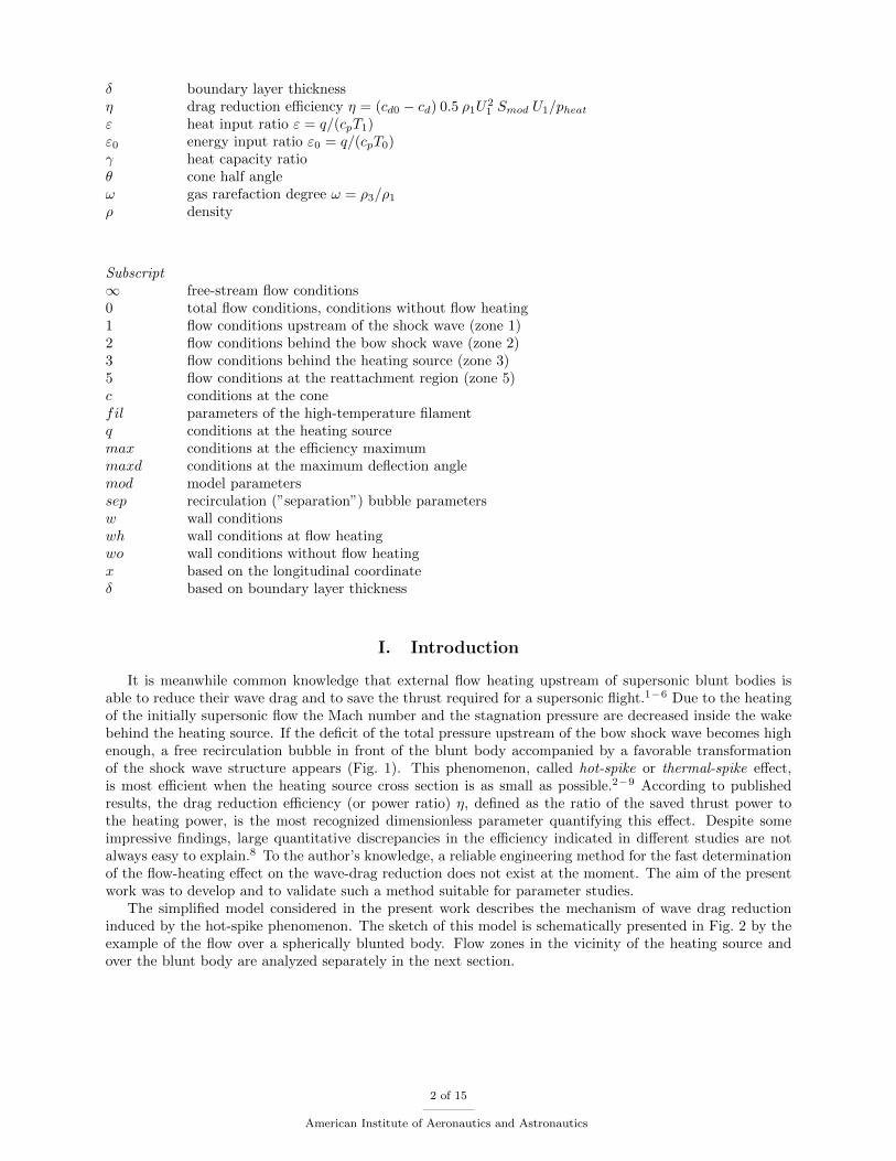
It is meanwhile common knowledge that external flow heating upstream of supersonic blunt bodies isable to reduce their wave drag and to save the thrust required for a supersonic flight.1−6 Due to the heatingof the initially supersonic flow the Mach number and the stagnation pressure are decreased inside the wakebehind the heating source. If the deficit of the total pressure upstream of the bow shock wave becomes highenough, a free recirculation bubble in front of the blunt body accompanied by a favorable transformationof the shock wave structure appears (Fig. 1). This phenomenon, called hot-spike or thermal-spike effect,is most efficient when the heating source cross section is as small as possible.2−9 According to publishedresults, the drag reduction efficiency (or power ratio) η, defined as the ratio of the saved thrust power tothe heating power, is the most recognized dimensionless parameter quantifying this effect. Despite someimpressive findings, large quantitative discrepancies in the efficiency indicated in different studies are notalways easy to explain.8 To the author’s knowledge, a reliable engineering method for the fast determinationof the flow-heating effect on the wave-drag reduction does not exist at the moment. The aim of the presentwork was to develop and to validate such a method suitable for parameter studies.
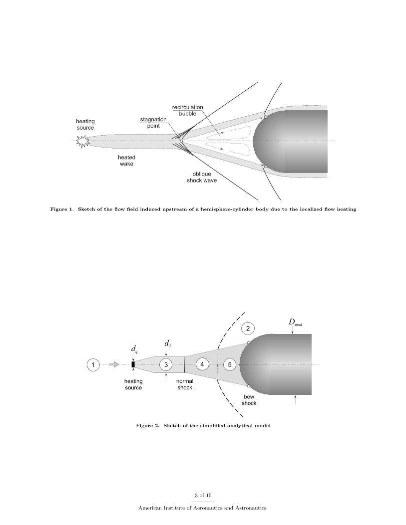
The simplified model considered in the present work describes the mechanism of wave drag reductioninduced by the hot-spike phenomenon. The sketch of this model is schematically presented in Fig. 2 by theexample of the flow over a spherically blunted body. Flow zones in the vicinity of the heating source andover the blunt body are analyzed separately in the next section.
2 of 15
American Institute of Aeronautics and Astronautics
heatingsource
heatedwake
stagnationpoint
obliqueshock wave
recirculationbubble
Figure 1. Sketch of the flow field induced upstream of a hemisphere-cylinder body due to the localized flow heating
1
2
heatingsource
normalshock
bowshock
dq
d3
3 4 5
Dmod
Figure 2. Sketch of the simplified analytical model
3 of 15
American Institute of Aeronautics and Astronautics
II. Model and method description
II.A. Analysis of the flow behind the heating source
At a sufficient distance downstream from the heating source, where the expansion of the heated wake dueto the pressure equalization is completed, the flow parameters in the absence of a body can be calculatedassuming internal energy addition at constant static pressure conditions. According to OSWATITSCH,10
the temperatures and densities upstream and downstream of the heating source for the ideal gas conditionsat constant specific heats are related to each other as follows:
T3
T1=ρ1
ρ3= 1 +
q
cpT1= 1 + ε =
1
ω(1)
The subscripts 1 and 3 refer to the zone labels in Fig. 2. Dimensionless parameters ε and ω denoting herethe heat input ratio ε = q/(cpT1) and the gas-rarefaction degree ω = ρ3/ρ1 are linked to each other anddescribe the extent of the flow heating alternatively. The specific heat power q introduced to the flow can bedetermined as q = pheat/mq = pheat/(ρ1U1Sq), whereby pheat is the heating power, ρ1 and U1 are the densityand velocity of the undisturbed incoming flow, and Sq is the cross-sectional area of the energy source.
The equation of motion applied to the heated streamtube ρu du = −dp gives a constant-velocity flow atconstant pressure, so that the Mach number is changed by increasing sound velocity only
M3
M1=
√T1
T3=
√1
1 + ε. (2)
Hence, the Mach number decreases due to the heating and the resulting flow becomes subsonic when theheating power is high enough. This behavior is additionally supported by the favorable radial extension ofthe heated streamtube (see Fig. 2, d1 = dq), taking place in accordance with the density reduction
d3
d1=
√ρ1
ρ3=√
1 + ε (3)
It is important to note that the effect of the thermal flow chocking ,11,12 which induces a secondary shockwave upstream of the input zone at high heating rates, is disregarded in this simplified consideration. Inthis case the stagnation pressure p03 in zone 3 can easily be determined from the valid isentropic relations,or alternatively, directly by the relation:10
lnp03
p01=
γ
γ − 1[ln (1 + ε0)− ln (1 + ε)] , (4)
where γ is the ratio of specific heats and ε0 denotes the energy input ratio ε0 = q/(cpT0). Finally, thePitot pressure p′03 in the heated wake can be calculated on request at locally supersonic flow conditions(M3 ≥ 1) by the Rayleigh supersonic Pitot formula.13 Hence, the application of Eqs. 1 - 4 gives a possibilityto determine all relevant flow parameters in the heated wake as a function of the heat input ratio ε.
II.B. Analysis of the flow with nonuniform stagnation pressure over a blunt body of revolution
The pioneering analysis of supersonic flows over blunt bodies placed in a region with nonuniform stagnationpressure at nearly constant static pressure (wakes or boundary layers) has been made by MOECKEL.14
According to his analysis covering two-dimensional and axially symmetric flows, the existence of a localizedstagnation-pressure deficit inside a wake upstream of the blunt body (even if velocity near the axis issupersonic) inevitably leads to the formation of a ”dead-air region” with a free stagnation point aheadof it. This recirculation region is commonly also referred to as ”separation” or ”front-separation” zonemeaning the flow dividing at the free stagnation point.
The underlying analytical model for the most developed case with a large-scale separation bubble pre-sumes that: 1) the outer border of the separated region is straight, 2) the reattachment of the separatedshear layer takes place tangentially to the nose/shoulder of the body, as well as 3) the pressure in theseparated region is constant. The most important conclusion of the cited work states that, at given bodythickness/diameter Dmod and Mach number, a minimum length of the wake (or of the solid-spike) L existsbeneath which a steady wedge-/conical-type separation region cannot occur.
4 of 15
American Institute of Aeronautics and Astronautics

Although the effect of the heated wake on the flow ahead of the blunt bodies was not explicitly investi-gated in the cited work, the most important cornerstones typically for flows with front separation (solid orthermal spikes, etc.) are definitely at the right place. Above all, the existence of a quasi-steady conical-typeseparation zone with a lower limit for the length of a solid and thermal spike has been proved in numerousexperimental and numerical works and is undisputed. However, the assumptions of the constant pressureinside the separation bubble and the smooth tangential reattachment of the flow to the body seem to be someover-simplifications quite useful only as a first approximation. Based on findings of more recent numericalsimulations, the concept of the isobaric recirculation zone is well applicable only to the front part of theseparation zone.4,15–17 Its rear part, the reattachment region, reveals distinct pressure gradients in mostinvestigated cases and pressure levels which are distinctly higher than expected from the intensity of theseparation shock wave.
II.C. Simplified prediction method for flow-heating effect
According to the described model concept, the free recirculation flow ahead of a blunt body occurs when thePitot pressure in the heated wake p′03 (or stagnation pressure p03 = p′03 at locally subsonic flow conditions inthe heated wakea) becomes equal to or less than the initial static pressure p2 in the stagnation point regionof the body. The pressure level inside the separation zone (see Fig. 2, zones 4 and 5) is assumed to increasefrom p4 = p′03 at the free stagnation point in zone 4 to a higher level p5 in zone 5. The reason for thispressure increase is the partial stagnation of the incoming flow due to the non-tangential reattachment ofthe shear layer to the nose surface, which cannot be analytically calculated. In order to simplify the method,the resulting pressure level in zone 5 is proposed to estimate as a linear composition of the Pitot pressurelevels in zones 1 and 3:
p5 = Kpres p′01 + (1−Kpres) p
′03 (5)
The parameter Kpres = f(ε) is the fraction of the local pressure level assumed to be induced by the unheatedflow, which has values between 0 and 1 and should be defined empirically.
For bodies with initially detached bow-shock waves, the separation bubble induced due to heating expandsin radial direction as long as the pressure inside it remains lower than the initial local static pressure at thebody surface p2(s), where s is the streamwise coordinate along the surface. It is to be expected that thepressures p5 and p2 should be in balance at the junction of the outer border of the recirculation zone andthe surface contour (circular markers in Fig. 2). Hence, the wall pressure pw(s) at the nose part of thebody is estimated to be equal to p5(ε) inside of zone 5, and equal to p2(s) outside of it. According to thepresent method, the initial pressure distribution p2(s) on the hemispherical model can be estimated as usualby the modified Newtonian theory. For rounded and pointed cones with sonic corners (detached bow-shockwaves), the Sin2-Deficiency Method18 is supposed to give the best results. The resulting forebody drag canbe simply evaluated by integration of the pressure differences acting on the nose surface:
cd =1
0.5ρ1U21Rmod
∫ Rmod
0
(pw − p1)dr (6)
Unfortunately, this simple concept for the estimation of the cross-sectional extent of the separation bubblecan not be used for slender pointed cones, having initially attached conical bow-shock waves and nominallyconstant wall pressures at the surface. Similar to the interaction of a flat-plate boundary layer with theshock wave generated by a 2-D compression ramp of finite height19 (forward-facing step with an inclinedfront panel), it should be expected that the induced recirculation bubble reaches its full scale when thebow-shock intensity is high enough for the given heated wake profile. For the mentioned 2-D interaction casewith a relative thin boundary layer the transformation of the flow topology from the compression-ramp (CR)to the forward-facing-step (FFS) type occurs very likely when the ramp deflection angle becomes equal tothe maximum deflection angle and the bow shock detaches from the nose.19 If the boundary layer thicknesshas the same order of magnitude as the ramp height, the transformation to each other is fluid and occurssignificantly earlier because each CR-type separation can easily reach full-scale extent even at moderateshock intensities.
From this point of view, the heated-wake flow with a CR-type separation bubble is the most commoncase, while the full-scale separation constitutes only the final state of the flow development and means its
aAt supersonic flow conditions in the heated wake (M3 ≥ 1) a normal shock is assumed to appear upstream of the freerecirculation zone (see Fig. 2)
5 of 15
American Institute of Aeronautics and Astronautics
simplification. To extend the proposed approach for more slender bodies with initially attached bow-shockwaves, a fraction parameter Ksep, quantifying the normalized cross-sectional area of the surface covered bythe separation bubble, should be introduced. Using this parameter the flat-rate calculation of the inducedforebody drag should be possible regardless of the type of separation bubble as follows:
cd =Ksep(pwh − p1) + (1−Ksep)(pwo − p1)
0.5ρ1U21
(7)
Here, pwh and pwo are the constant pressure levels on the surface of the cone with and without flow heating(pwh = p5, pwo = p2).
III. Model adjustment on the basis of results for pointed cones9
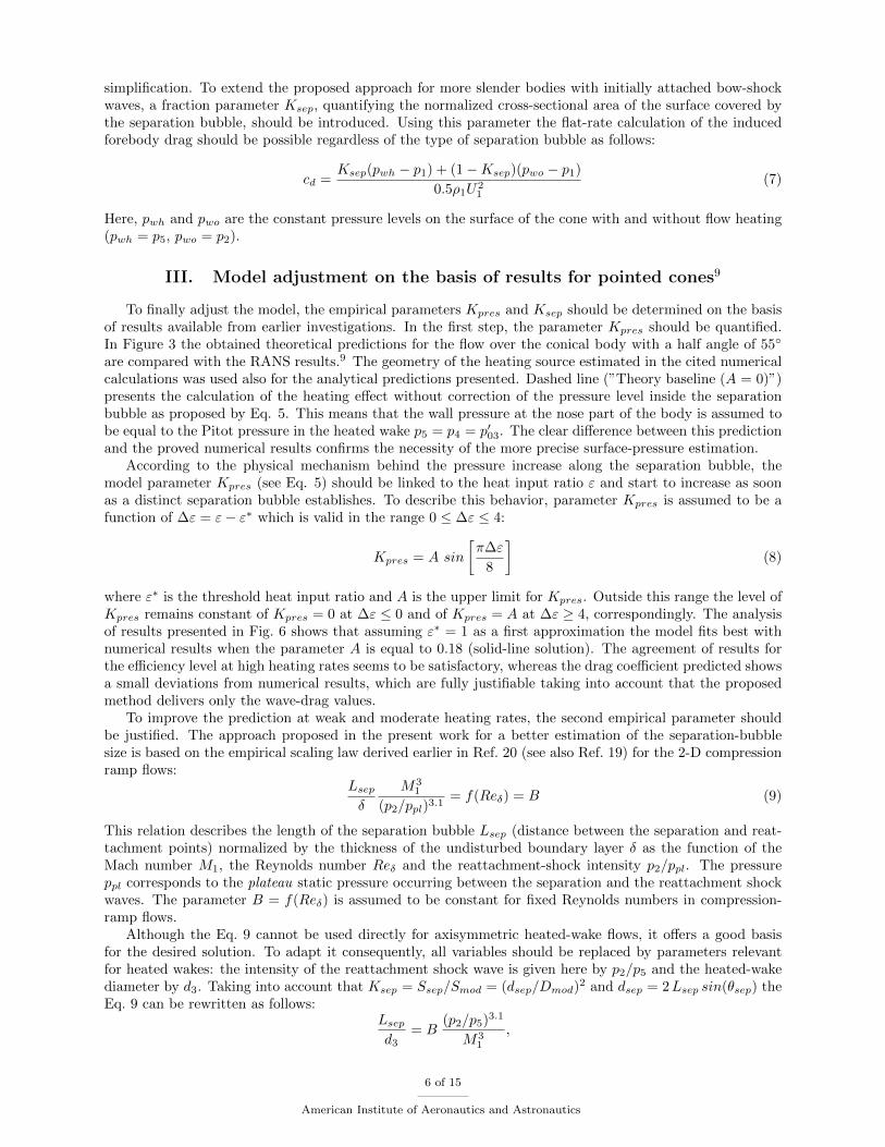
To finally adjust the model, the empirical parameters Kpres and Ksep should be determined on the basisof results available from earlier investigations. In the first step, the parameter Kpres should be quantified.In Figure 3 the obtained theoretical predictions for the flow over the conical body with a half angle of 55◦
are compared with the RANS results.9 The geometry of the heating source estimated in the cited numericalcalculations was used also for the analytical predictions presented. Dashed line (”Theory baseline (A = 0)”)presents the calculation of the heating effect without correction of the pressure level inside the separationbubble as proposed by Eq. 5. This means that the wall pressure at the nose part of the body is assumed tobe equal to the Pitot pressure in the heated wake p5 = p4 = p′03. The clear difference between this predictionand the proved numerical results confirms the necessity of the more precise surface-pressure estimation.
According to the physical mechanism behind the pressure increase along the separation bubble, themodel parameter Kpres (see Eq. 5) should be linked to the heat input ratio ε and start to increase as soonas a distinct separation bubble establishes. To describe this behavior, parameter Kpres is assumed to be afunction of ∆ε = ε− ε∗ which is valid in the range 0 ≤ ∆ε ≤ 4:
Kpres = A sin
[π∆ε
8
](8)
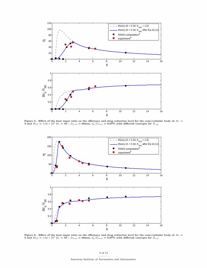
where ε∗ is the threshold heat input ratio and A is the upper limit for Kpres. Outside this range the level ofKpres remains constant of Kpres = 0 at ∆ε ≤ 0 and of Kpres = A at ∆ε ≥ 4, correspondingly. The analysisof results presented in Fig. 6 shows that assuming ε∗ = 1 as a first approximation the model fits best withnumerical results when the parameter A is equal to 0.18 (solid-line solution). The agreement of results forthe efficiency level at high heating rates seems to be satisfactory, whereas the drag coefficient predicted showsa small deviations from numerical results, which are fully justifiable taking into account that the proposedmethod delivers only the wave-drag values.
To improve the prediction at weak and moderate heating rates, the second empirical parameter shouldbe justified. The approach proposed in the present work for a better estimation of the separation-bubblesize is based on the empirical scaling law derived earlier in Ref. 20 (see also Ref. 19) for the 2-D compressionramp flows:
Lsepδ
M31
(p2/ppl)3.1= f(Reδ) = B (9)
This relation describes the length of the separation bubble Lsep (distance between the separation and reat-tachment points) normalized by the thickness of the undisturbed boundary layer δ as the function of theMach number M1, the Reynolds number Reδ and the reattachment-shock intensity p2/ppl. The pressureppl corresponds to the plateau static pressure occurring between the separation and the reattachment shockwaves. The parameter B = f(Reδ) is assumed to be constant for fixed Reynolds numbers in compression-ramp flows.
Although the Eq. 9 cannot be used directly for axisymmetric heated-wake flows, it offers a good basisfor the desired solution. To adapt it consequently, all variables should be replaced by parameters relevantfor heated wakes: the intensity of the reattachment shock wave is given here by p2/p5 and the heated-wakediameter by d3. Taking into account that Ksep = Ssep/Smod = (dsep/Dmod)
2 and dsep = 2Lsep sin(θsep) theEq. 9 can be rewritten as follows:
Lsepd3
= B(p2/p5)3.1
M31
,
6 of 15
American Institute of Aeronautics and Astronautics
LsepDmod
= B(p2/p5)3.1
M31
d3
Dmod,
√Ksep =
dsepDmod
= 2 sin(θsep)B(p2/p5)3.1
M31
d3
Dmod.
Introducing the new variable C = [2 sin(θsep)B]2
the final equation for Ksep is then:
Ksep = C
[(p2/p5)3.1
M31
d3
Dmod
]2
(10)
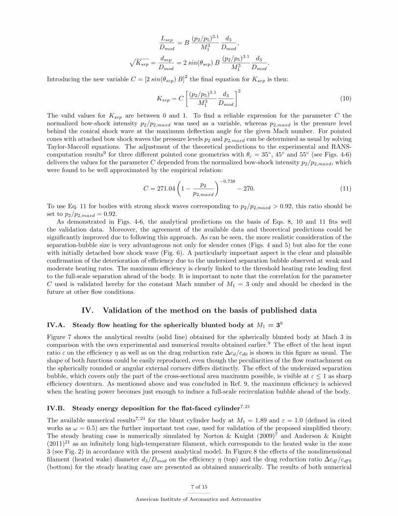
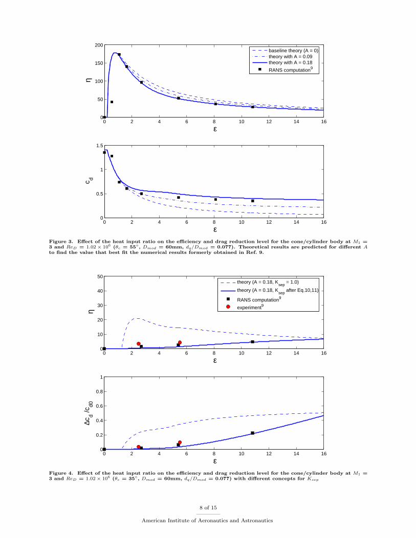
The valid values for Ksep are between 0 and 1. To find a reliable expression for the parameter C thenormalized bow-shock intensity p2/p2,maxd was used as a variable, whereas p2,maxd is the pressure levelbehind the conical shock wave at the maximum deflection angle for the given Mach number. For pointedcones with attached bow shock waves the pressure levels p2 and p2,maxd can be determined as usual by solvingTaylor-Maccoll equations. The adjustment of the theoretical predictions to the experimental and RANS-computation results9 for three different pointed cone geometries with θc = 35◦, 45◦ and 55◦ (see Figs. 4-6)delivers the values for the parameter C depended from the normalized bow-shock intensity p2/p2,maxd, whichwere found to be well approximated by the empirical relation:
C = 271.04
(1− p2
p2,maxd
)−0.738
− 270. (11)
To use Eq. 11 for bodies with strong shock waves corresponding to p2/p2,maxd > 0.92, this ratio should beset to p2/p2,maxd = 0.92.
As demonstrated in Figs. 4-6, the analytical predictions on the basis of Eqs. 8, 10 and 11 fits wellthe validation data. Moreover, the agreement of the available data and theoretical predictions could besignificantly improved due to following this approach. As can be seen, the more realistic consideration of theseparation-bubble size is very advantageous not only for slender cones (Figs. 4 and 5) but also for the conewith initially detached bow shock wave (Fig. 6). A particularly important aspect is the clear and plausibleconfirmation of the deterioration of efficiency due to the undersized separation bubble observed at weak andmoderate heating rates. The maximum efficiency is clearly linked to the threshold heating rate leading firstto the full-scale separation ahead of the body. It is important to note that the correlation for the parameterC used is validated hereby for the constant Mach number of M1 = 3 only and should be checked in thefuture at other flow conditions.
IV. Validation of the method on the basis of published data
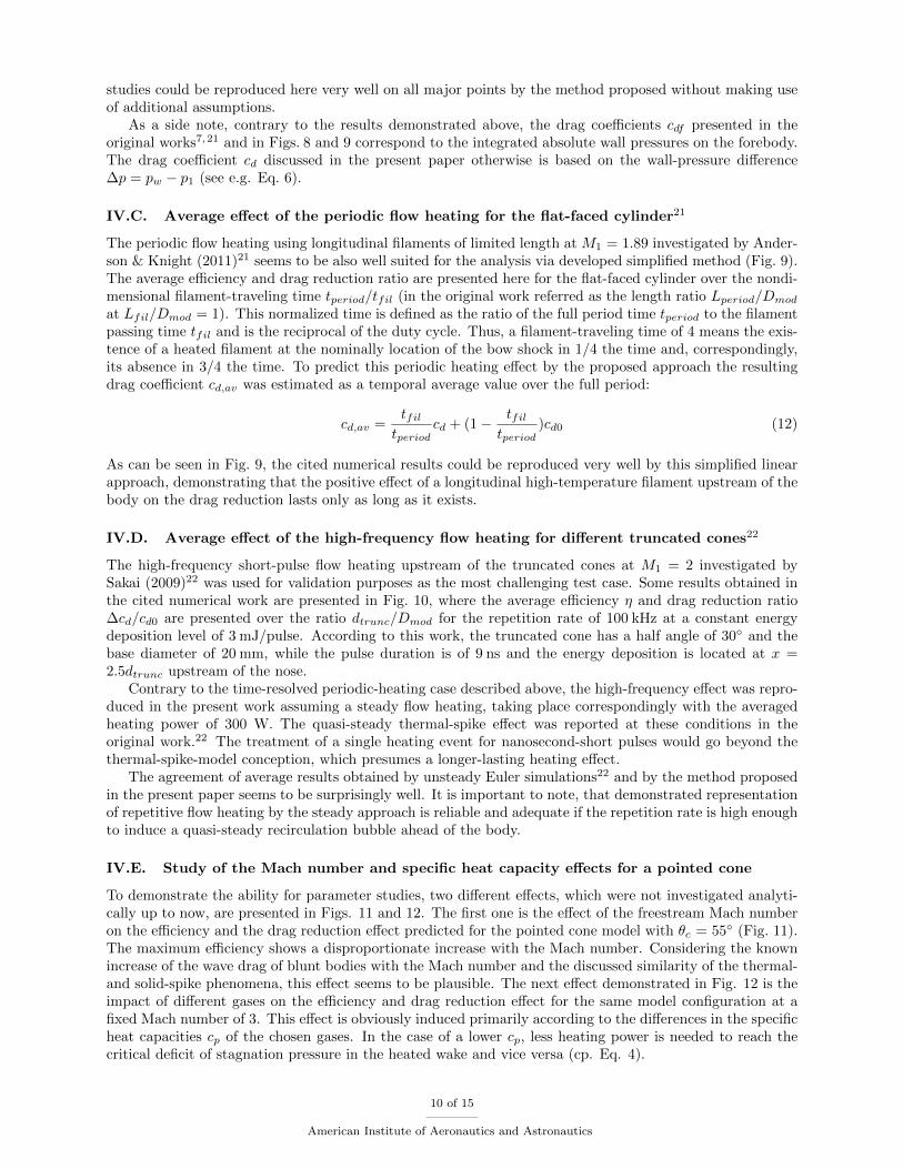
IV.A. Steady flow heating for the spherically blunted body at M1 = 39
Figure 7 shows the analytical results (solid line) obtained for the spherically blunted body at Mach 3 incomparison with the own experimental and numerical results obtained earlier.9 The effect of the heat inputratio ε on the efficiency η as well as on the drag reduction rate ∆cd/cd0 is shown in this figure as usual. Theshape of both functions could be easily reproduced, even though the peculiarities of the flow reattachment onthe spherically rounded or angular external corners differs distinctly. The effect of the undersized separationbubble, which covers only the part of the cross-sectional area maximum possible, is visible at ε ≤ 1 as sharpefficiency downturn. As mentioned above and was concluded in Ref. 9, the maximum efficiency is achievedwhen the heating power becomes just enough to induce a full-scale recirculation bubble ahead of the body.
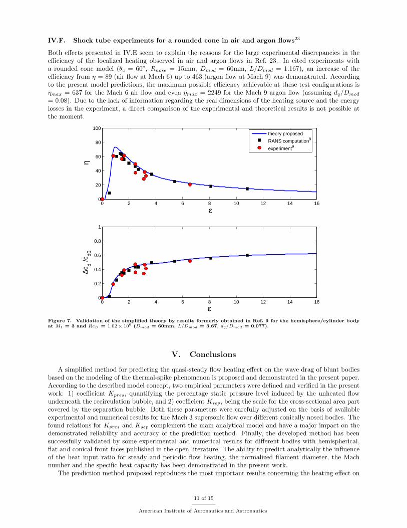
IV.B. Steady energy deposition for the flat-faced cylinder7,21
The available numerical results7,21 for the blunt cylinder body at M1 = 1.89 and ε = 1.0 (defined in citedworks as ω = 0.5) are the further important test case, used for validation of the proposed simplified theory.The steady heating case is numerically simulated by Norton & Knight (2009)7 and Anderson & Knight(2011)21 as an infinitely long high-temperature filament, which corresponds to the heated wake in the zone3 (see Fig. 2) in accordance with the present analytical model. In Figure 8 the effects of the nondimensionalfilament (heated wake) diameter d3/Dmod on the efficiency η (top) and the drag reduction ratio ∆cdf/cdf0
(bottom) for the steady heating case are presented as obtained numerically. The results of both numerical
7 of 15
American Institute of Aeronautics and Astronautics
0 2 4 6 8 10 12 14 160
50
100
150
200
ε
η
baseline theory (A = 0)theory with A = 0.09theory with A = 0.18
RANS computation9
0 2 4 6 8 10 12 14 160
0.5
1
1.5
ε
cd
Figure 3. Effect of the heat input ratio on the efficiency and drag reduction level for the cone/cylinder body at M1 =3 and ReD = 1.02 × 10⁶ (θc = 55◦, Dmod = 60mm, dq/Dmod = 0.077). Theoretical results are predicted for different Ato find the value that best fit the numerical results formerly obtained in Ref. 9.
0 2 4 6 8 10 12 14 160
10
20
30
40
50
ε
η
theory (A = 0.18, Ksep
= 1.0)
theory (A = 0.18, Ksep
after Eq.10,11)
RANS computation9
experiment9
0 2 4 6 8 10 12 14 160
0.2
0.4
0.6
0.8
1
ε
∆cd /c
d0
Figure 4. Effect of the heat input ratio on the efficiency and drag reduction level for the cone/cylinder body at M1 =3 and ReD = 1.02× 10⁶ (θc = 35◦, Dmod = 60mm, dq/Dmod = 0.077) with different concepts for Ksep
8 of 15
American Institute of Aeronautics and Astronautics
0 2 4 6 8 10 12 14 160
20
40
60
80
100
120
ε
η
theory (A = 0.18, Ksep
= 1.0)
theory (A = 0.18, Ksep
after Eq.10,11)
RANS computation9
experiment9
0 2 4 6 8 10 12 14 160
0.2
0.4
0.6
0.8
1
ε
∆cd /c
d0
Figure 5. Effect of the heat input ratio on the efficiency and drag reduction level for the cone/cylinder body at M1 =3 and ReD = 1.02× 10⁶ (θc = 45◦, Dmod = 60mm, dq/Dmod = 0.077) with different concepts for Ksep
0 2 4 6 8 10 12 14 160
50
100
150
200
ε
η
theory (A = 0.18, Ksep
= 1.0)
theory (A = 0.18, Ksep
after Eq.10,11)
RANS computation9
experiment9
0 2 4 6 8 10 12 14 160
0.2
0.4
0.6
0.8
1
ε
∆cd /c
d0
Figure 6. Effect of the heat input ratio on the efficiency and drag reduction level for the cone/cylinder body at M1 =3 and ReD = 1.02× 10⁶ (θc = 55◦, Dmod = 60mm, dq/Dmod = 0.077) with different concepts for Ksep
9 of 15
American Institute of Aeronautics and Astronautics
studies could be reproduced here very well on all major points by the method proposed without making useof additional assumptions.
As a side note, contrary to the results demonstrated above, the drag coefficients cdf presented in theoriginal works7,21 and in Figs. 8 and 9 correspond to the integrated absolute wall pressures on the forebody.The drag coefficient cd discussed in the present paper otherwise is based on the wall-pressure difference∆p = pw − p1 (see e.g. Eq. 6).
IV.C. Average effect of the periodic flow heating for the flat-faced cylinder21
The periodic flow heating using longitudinal filaments of limited length at M1 = 1.89 investigated by Ander-son & Knight (2011)21 seems to be also well suited for the analysis via developed simplified method (Fig. 9).The average efficiency and drag reduction ratio are presented here for the flat-faced cylinder over the nondi-mensional filament-traveling time tperiod/tfil (in the original work referred as the length ratio Lperiod/Dmod
at Lfil/Dmod = 1). This normalized time is defined as the ratio of the full period time tperiod to the filamentpassing time tfil and is the reciprocal of the duty cycle. Thus, a filament-traveling time of 4 means the exis-tence of a heated filament at the nominally location of the bow shock in 1/4 the time and, correspondingly,its absence in 3/4 the time. To predict this periodic heating effect by the proposed approach the resultingdrag coefficient cd,av was estimated as a temporal average value over the full period:
cd,av =tfiltperiod
cd + (1− tfiltperiod
)cd0 (12)
As can be seen in Fig. 9, the cited numerical results could be reproduced very well by this simplified linearapproach, demonstrating that the positive effect of a longitudinal high-temperature filament upstream of thebody on the drag reduction lasts only as long as it exists.
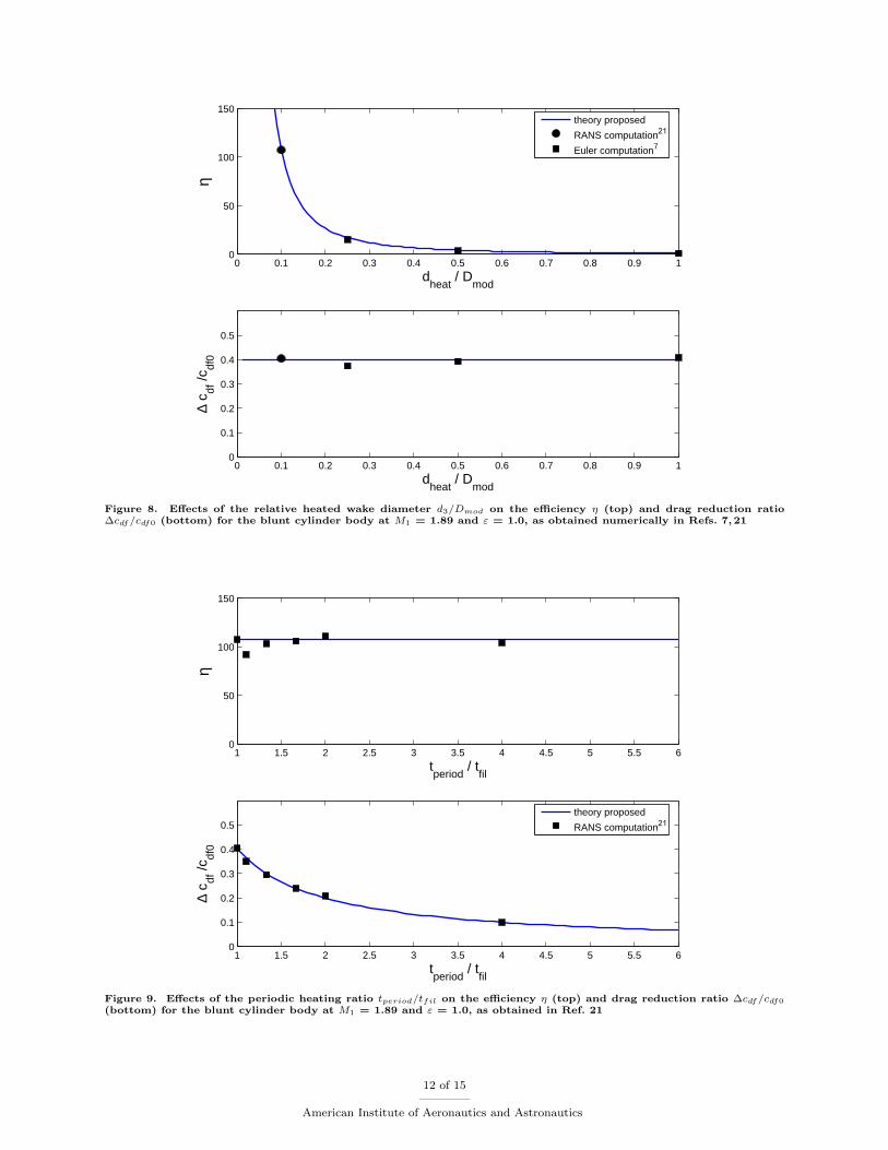
IV.D. Average effect of the high-frequency flow heating for different truncated cones22
The high-frequency short-pulse flow heating upstream of the truncated cones at M1 = 2 investigated bySakai (2009)22 was used for validation purposes as the most challenging test case. Some results obtained inthe cited numerical work are presented in Fig. 10, where the average efficiency η and drag reduction ratio∆cd/cd0 are presented over the ratio dtrunc/Dmod for the repetition rate of 100 kHz at a constant energydeposition level of 3 mJ/pulse. According to this work, the truncated cone has a half angle of 30◦ and thebase diameter of 20 mm, while the pulse duration is of 9 ns and the energy deposition is located at x =2.5dtrunc upstream of the nose.
Contrary to the time-resolved periodic-heating case described above, the high-frequency effect was repro-duced in the present work assuming a steady flow heating, taking place correspondingly with the averagedheating power of 300 W. The quasi-steady thermal-spike effect was reported at these conditions in theoriginal work.22 The treatment of a single heating event for nanosecond-short pulses would go beyond thethermal-spike-model conception, which presumes a longer-lasting heating effect.
The agreement of average results obtained by unsteady Euler simulations22 and by the method proposedin the present paper seems to be surprisingly well. It is important to note, that demonstrated representationof repetitive flow heating by the steady approach is reliable and adequate if the repetition rate is high enoughto induce a quasi-steady recirculation bubble ahead of the body.
IV.E. Study of the Mach number and specific heat capacity effects for a pointed cone
To demonstrate the ability for parameter studies, two different effects, which were not investigated analyti-cally up to now, are presented in Figs. 11 and 12. The first one is the effect of the freestream Mach numberon the efficiency and the drag reduction effect predicted for the pointed cone model with θc = 55◦ (Fig. 11).The maximum efficiency shows a disproportionate increase with the Mach number. Considering the knownincrease of the wave drag of blunt bodies with the Mach number and the discussed similarity of the thermal-and solid-spike phenomena, this effect seems to be plausible. The next effect demonstrated in Fig. 12 is theimpact of different gases on the efficiency and drag reduction effect for the same model configuration at afixed Mach number of 3. This effect is obviously induced primarily according to the differences in the specificheat capacities cp of the chosen gases. In the case of a lower cp, less heating power is needed to reach thecritical deficit of stagnation pressure in the heated wake and vice versa (cp. Eq. 4).
10 of 15
American Institute of Aeronautics and Astronautics
IV.F. Shock tube experiments for a rounded cone in air and argon flows23
Both effects presented in IV.E seem to explain the reasons for the large experimental discrepancies in theefficiency of the localized heating observed in air and argon flows in Ref. 23. In cited experiments witha rounded cone model (θc = 60◦, Rnose = 15mm, Dmod = 60mm, L/Dmod = 1.167), an increase of theefficiency from η = 89 (air flow at Mach 6) up to 463 (argon flow at Mach 9) was demonstrated. Accordingto the present model predictions, the maximum possible efficiency achievable at these test configurations isηmax = 637 for the Mach 6 air flow and even ηmax = 2249 for the Mach 9 argon flow (assuming dq/Dmod
= 0.08). Due to the lack of information regarding the real dimensions of the heating source and the energylosses in the experiment, a direct comparison of the experimental and theoretical results is not possible atthe moment.
0 2 4 6 8 10 12 14 160
20
40
60
80
100
ε
η
theory proposed
RANS computation9
experiment9
0 2 4 6 8 10 12 14 160
0.2
0.4
0.6
0.8
1
ε
∆cd /c
d0
Figure 7. Validation of the simplified theory by results formerly obtained in Ref. 9 for the hemisphere/cylinder bodyat M1 = 3 and ReD = 1.02× 10⁶ (Dmod = 60mm, L/Dmod = 3.67, dq/Dmod = 0.077).
V. Conclusions
A simplified method for predicting the quasi-steady flow heating effect on the wave drag of blunt bodiesbased on the modeling of the thermal-spike phenomenon is proposed and demonstrated in the present paper.According to the described model concept, two empirical parameters were defined and verified in the presentwork: 1) coefficient Kpres, quantifying the percentage static pressure level induced by the unheated flowunderneath the recirculation bubble, and 2) coefficient Ksep, being the scale for the cross-sectional area partcovered by the separation bubble. Both these parameters were carefully adjusted on the basis of availableexperimental and numerical results for the Mach 3 supersonic flow over different conically nosed bodies. Thefound relations for Kpres and Ksep complement the main analytical model and have a major impact on thedemonstrated reliability and accuracy of the prediction method. Finally, the developed method has beensuccessfully validated by some experimental and numerical results for different bodies with hemispherical,flat and conical front faces published in the open literature. The ability to predict analytically the influenceof the heat input ratio for steady and periodic flow heating, the normalized filament diameter, the Machnumber and the specific heat capacity has been demonstrated in the present work.
The prediction method proposed reproduces the most important results concerning the heating effect on
11 of 15
American Institute of Aeronautics and Astronautics
0 0.1 0.2 0.3 0.4 0.5 0.6 0.7 0.8 0.9 10
50
100
150
dheat
/ Dmod
η
theory proposed RANS computation21
Euler computation7
0 0.1 0.2 0.3 0.4 0.5 0.6 0.7 0.8 0.9 10
0.1
0.2
0.3
0.4
0.5
dheat
/ Dmod
∆ c df
/cdf
0
Figure 8. Effects of the relative heated wake diameter d3/Dmod on the efficiency η (top) and drag reduction ratio∆cdf/cdf0 (bottom) for the blunt cylinder body at M1 = 1.89 and ε = 1.0, as obtained numerically in Refs. 7, 21
1 1.5 2 2.5 3 3.5 4 4.5 5 5.5 60
50
100
150
tperiod
/ tfil
η
1 1.5 2 2.5 3 3.5 4 4.5 5 5.5 60
0.1
0.2
0.3
0.4
0.5
tperiod
/ tfil
∆ c df
/cdf
0
theory proposed RANS computation21
Figure 9. Effects of the periodic heating ratio tperiod/tfil on the efficiency η (top) and drag reduction ratio ∆cdf/cdf0
(bottom) for the blunt cylinder body at M1 = 1.89 and ε = 1.0, as obtained in Ref. 21
12 of 15
American Institute of Aeronautics and Astronautics
0 0.1 0.2 0.3 0.4 0.5 0.6 0.7 0.8 0.9 10
5
10
15
20
25
30
dtrunc
/ Dmod
η
Theory proposed CFD computation22
0 0.1 0.2 0.3 0.4 0.5 0.6 0.7 0.8 0.9 10
0.2
0.4
0.6
0.8
1
dtrunc
/ Dmod
c d / c d0
Figure 10. Average effect of the short-pulse flow heating for different truncated cones at Mach 2 for the case with anenergy deposition of 3 mJ/pulse at 100 kHz introduced at the distance x/dtrunc = 2.5 upstream of the nose.22
0 2 4 6 8 10 12 14 160
200
400
600
800
1000
ε
η
M1 = 2
M1 = 3
M1 = 4
M1 = 5
M1 = 6
0 2 4 6 8 10 12 14 160
0.5
1
1.5
2
ε
cd
Figure 11. Effect of the freestream Mach number on the efficiency η (top) and drag coefficient cd (bottom) predictedfor a cone/cylinder body with θc = 55◦.
13 of 15
American Institute of Aeronautics and Astronautics

0 2 4 6 8 10 12 14 160
50
100
150
200
250
300
ε
η
Carbon dioxideArgonAir
0 2 4 6 8 10 12 14 160.2
0.4
0.6
0.8
1
1.2
1.4
1.6
ε
cd
Figure 12. Effect of different gases on the efficiency η (top) and drag coefficient cd (bottom) for a cone/cylinder bodyat M1 = 3 and θc = 55◦.
the aerodynamic performance of bodies with initially attached and detached bow-shock waves and seems tobe robust and precise enough for desired parametric studies. The obtained results and the underlying modelitself can help to advance the understanding of the processes behind the wave drag reduction effects of theenergy deposition.
References
1Maurer, F., Brungs, W.: Beeinflussung des Widerstands und der Kopfwelle durch Warmezufuhr im Staupunktsbereichstumpfer Korper bei Uberschallanstromung. Jahrbuch 1968 der DGLR, Koln, 174-189, (1968) (in German)
2Georgievsky, P. Yu., Levin, V. A.: Supersonic Flow over Bodies in the Presence of External Energy Input Sources. Pismav Zhurn. Tekhn. Phiz.,14(8), 684-687, (1988) (in Russian)
3Nemchinov, I.V., Artem’ev, V.I., Bergelson, V.I., Khazins, V.M., Orlova, T.I., Rybakov, V.A.: Rearrangement of thebow shock shape using a ”hot spike”. Shock Waves, 4(1), 35-40, (1994)
4Riggins, D., Nelson, H.F., Johnson, E.: Blunt-Body Wave Drag Reduction Using Focused Energy Deposition. AIAA J.,37(4), 460-467, (1999)
5Zheltovodov, A.A.: Development of the studies on energy deposition for application to the problems of supersonicaerodynamics. Preprint No. 10-2002, ITAM, RAS, SB, 43 p., Novosibirsk, (2002)
6Knight, D., Kuchinskiy, V., Kuranov, A., Sheikin, E.: Survey of aerodynamic flow control at high speed by energydeposition. AIAA-2003-0525, (2003)
7Norton, K., Knight, D.D.: Thermal Effects of Microwave Energy Deposition in Supersonic Flow. AIAA-2009-1224, (2009)8Schulein, E., Zheltovodov, A.A.: Effects of localized flow heating by arc discharge upstream of non-slender bodies. Shock
Waves, 21(4), 383-396, (2011)9Schulein, E., Bornhoft, E.: Potential of Localized Flow Heating for Wave Drag Reduction. In: 28th International
Symposium on Shock Waves Shock Waves, Vol. 1 (VIII), Springer, Heidelberg New York, 615-621, (2012)10Oswatitsch, K.: Gasdynamik. Springer, Wien, 456 p., (1952) (in German)11Vlasov, V.V., Grudnitskii, B.G., Rygalin, V.N.: Gas Dynamics with Local Energy Release in Supersonic and Subsonic
Flow. Fluid Dynamics, 30(2), 275-280, (1995)12Georgievsky, P. Yu., Levin, V. A.: Bow Shock Wave Structures Control by Pulse-Periodic Energy Input. AIAA-2004-1019,
(2004)13Liepmann, H.W., Roshko, A.: Elements of Gasdynamics. John Wiley & Sons, Inc., New York, London (1960)14Moeckel, W.E.: Flow Separation Ahead of Blunt Bodies at Supersonic Speeds. NACA TN 2418, Washington, (1951)
14 of 15
American Institute of Aeronautics and Astronautics
15Guvernjuk, S., Savinov, K.: Isobaric Separation Structures in Supersonic Flows with a Localized Inhomogeneity. DokladyPhysics, 52(3), 151-155, (2007)
16Georgievsky, P.Yu., Levin, V. A., Suturin, O.G.: Front Separation Regions Initiated by Upstream Energy Deposition.AIAA-2008-1355, (2008)
17Bornhoft, E.: Windkanaluntersuchungen zur Stromungssteuerung mittels Energiezufuhr. Master thesis, UnivesitatGottingen & DLR Gttingen, (2010) (in German)
18Love, E.S., Woods, W.C., Rainey, R.W., Ashby, G.C.Jr.: Some Topics in Hypersonic Body Shaping. AIAA-1969-181,(1969)
19Knight, D.D., Zheltovodov, A.A.: Ideal-gas - shock wave turbulent boundary layer interactions in supersonic flows andtheir modeling: two-dimensional interactions. In: Shock Wave - Boundary Layer Interactions, Chapter 4, Edited by H.Babinsky& J.Harvey. Cambridge University Press (2011)
20Zheltovodov,A.A., Schulein, E.: Peculiarities of turbulent separation development in disturbed boundary layers. Mod-elirovanie v Mekhanike (Modeling in Mechanics), 2, 1, 53-8, (1988) (in Russian)
21Anderson, K., Knight, D.D.: Interaction of heated filaments with a blunt cylinder in supersonic flow. Shock Waves,21:149-161, (2011)
22Sakai, T.: Supersonic Drag Performance of Truncated Cones with Repetitive Energy Depositions. International Journalof Aerospace Innovations, 1(1), 31-43, (2009)
23Satheesh, K., Jagadeesh, G.: Experimental Investigations of the Effect of Energy Deposition in Hypersonic Blunt BodyFlow Field. Shock Waves, 18(1), 53-70, (2008)
15 of 15
American Institute of Aeronautics and Astronautics