Embed Size (px)
Citation preview
NASA Engineering and Safety Center
Technical Assessment Report
Document #:
NESC-RP-08-
00487
Version:
1.0
Title:
CEV Parachute Assembly System Independent
Reliability Analysis
Page #:
1 of 109
NESC Request No.: TI-08-00487
Constellation Program (CxP)
Crew Exploration Vehicle (CEV)
Parachute Assembly System (CPAS)
Independent Design Reliability Assessment
NRB Review Date: August 26, 2010
NASA Engineering and Safety Center
Technical Assessment Report
Document #:
NESC-RP-
08-00487
Version:
1.0
Title:
CEV Parachute Assembly System Independent
Design Reliability Assessment
Page #:
2 of 109
NESC Request No.: TI-08-00487
Report Approval and Revision History
Approval and Document Revision History
NOTE: This document was approved at the August 26, 2010, NRB. This document was
submitted to the NESC Director on September 23, 2010, for configuration control.
Approved
Version:
Original Signature on File 9/24/10
1.0 NESC Director Date
Version Description of Revision Office of Primary
Responsibility Effective Date
1.0 Initial Release Mr. Michael J. Kelly,
NESC Back-Up
Principal Engineer
08/26/10
NASA Engineering and Safety Center
Technical Assessment Report
Document #:
NESC-RP-
08-00487
Version:
1.0
Title:
CEV Parachute Assembly System Independent
Design Reliability Assessment
Page #:
3 of 109
NESC Request No.: TI-08-00487
Table of Contents
Volume I: Technical Assessment Report
1.0 Notification and Authorization ........................................................................................ 7
2.0 Signature Page ................................................................................................................... 8
3.0 Team List ........................................................................................................................... 9 3.1 Acknowledgements ............................................................................................................. 9
4.0 Executive Summary ........................................................................................................ 11 4.1 Summary of Assessment ................................................................................................... 11 4.2 Apollo Program Reports ................................................................................................... 13
4.3 Design, Development, Testing, and Evaluation (DDT&E) Guiding Principles ............... 13
5.0 Assessment Plan .............................................................................................................. 17
6.0 Problem Description, Scope of Review, and Architectural Evolution ....................... 18 6.1 Problem Description ......................................................................................................... 18
6.2 Scope of Review ............................................................................................................... 19
6.3 Architectural Evolution ..................................................................................................... 21 6.3.1 Review Period 1—December 2008 through March 2009 ................................ 22
6.3.2 Review Period 2—April 2009 through August 2009 ....................................... 37 6.3.3 Review Period 3—September 2009 through April 2010 ................................. 43
6.4 PRA and other Reliability Products .................................................................................. 56 6.4.1 Review Period 1—December 2008 through March 2009 ................................ 56 6.4.2 Review Period 2—April 2009 through August 2009 ....................................... 59 6.4.3 Review Period 3—September 2009 through April 2010 ................................. 62
6.5 Requirements, Testing, Analyses, and Verification Planning .......................................... 63
6.5.1 Review Period 1—December 2008 through March 2009 ................................ 63 6.5.2 Review Period 2—April 2009 through August 2009 ....................................... 63
6.5.3 Review Period 3—September 2009 through April 2010 ................................. 65 6.5.4 Analysis ............................................................................................................ 66 6.5.5 Master Verification Plan .................................................................................. 68
6.6 Organizational Complexity ............................................................................................... 70
7.0 Data Analysis ................................................................................................................... 75 7.1 Interim Analytical Assessment of Project Information .................................................... 75
7.1.1 Review Period 1—December 2008 through March 2009 ................................ 76
NASA Engineering and Safety Center
Technical Assessment Report
Document #:
NESC-RP-
08-00487
Version:
1.0
Title:
CEV Parachute Assembly System Independent
Design Reliability Assessment
Page #:
4 of 109
NESC Request No.: TI-08-00487
7.1.2 Review Period 2—April 2009 through August 2009 ....................................... 77 7.1.3 Review Period 3—September 2009 through April 2010. ................................ 78
7.2 Final Analytical Assessment of CPAS Project Information ............................................. 78 7.2.1 Architecture ...................................................................................................... 79
7.2.1.1 Pack Volume Risks .......................................................................................... 79 7.2.1.2 Roll Control Risks ............................................................................................ 80 7.2.2 PRA and Other Reliability Products ................................................................ 82 7.2.2.1 PRA Estimation Methods ................................................................................. 82
7.2.2.2 Use of PRA Estimates for Design Decisions ................................................... 85 7.2.3 Requirements, Testing, Analyses, and Verification Planning.......................... 86
7.2.3.1 Requirements.................................................................................................... 86 7.2.3.2 Development Test Plan .................................................................................... 87
7.2.3.3 Ground Testing ................................................................................................ 89 7.2.3.4 Main Pack Retention System ........................................................................... 89 7.2.3.5 Forward Bay Cover .......................................................................................... 91
7.2.3.6 Parachute Near-Field Contact during Deployment .......................................... 92 7.2.3.7 Modeling and Simulation ................................................................................. 93
7.2.3.8 Uncertainty Analysis of Simulation Results .................................................... 94 7.2.3.9 Clustered Parachute Modeling ......................................................................... 95 7.2.3.10 Master Verification Plan .................................................................................. 95
7.2.4 Organizational Complexity Impact on Systems Integration ............................ 98
8.0 Findings, Observations, and NESC Recommendations ............................................ 101 8.1 Findings........................................................................................................................... 101
8.2 Observations ................................................................................................................... 102 8.3 NESC Recommendations................................................................................................ 103
9.0 Lessons Learned ............................................................................................................ 104
10.0 Definition of Terms ....................................................................................................... 105
11.0 Acronyms List ............................................................................................................... 106
12.0 References ...................................................................................................................... 108
NASA Engineering and Safety Center
Technical Assessment Report
Document #:
NESC-RP-
08-00487
Version:
1.0
Title:
CEV Parachute Assembly System Independent
Design Reliability Assessment
Page #:
5 of 109
NESC Request No.: TI-08-00487
List of Figures
Figure 6.1-1. CPAS Gen-1 Con Ops .................................................................................... 19 Figure 6.2-1. CPAS/CEV Boundaries .................................................................................. 20
Figure 6.3-1. Drogue Mortars ............................................................................................... 22 Figure 6.3-2. Drogue Harness Legs and Confluence Fitting Stowed ................................... 23 Figure 6.3-3. Drogue Parachutes .......................................................................................... 24 Figure 6.3-4. Main Parachute Confluence Fitting ................................................................ 25
Figure 6.3-5. Main Parachute Packs Stowed ........................................................................ 26 Figure 6.3-6. Main Parachute Pack Retention System at IDR-1 .......................................... 27
Figure 6.3-7. Main Parachutes Deploying ............................................................................ 28 Figure 6.3-8. Main Parachutes .............................................................................................. 29
Figure 6.3-9. Rotation Torque Limiter Keeper for Main Harness Legs ............................... 30 Figure 6.3-10. Rotation Torque Limiter Keeper for Main Harness Legs, Deployed ............. 31 Figure 6.3-11. Rotation Torque Limiter Keeper for Main Harness Legs, Deployed Detail... 32
Figure 6.3-12. Auxiliary Parachutes ....................................................................................... 33 Figure 6.3-13. Pilot Parachutes Stowed .................................................................................. 34
Figure 6.3-14. Pilot Parachutes Deployed .............................................................................. 35 Figure 6.3-15. Drogue Harness Legs Stowed and Deployed, with Dual Confluence Rings .. 36 Figure 6.3-16. Drogue Harness Leg Attachment Fittings Detail ............................................ 37
Figure 6.3-17. Zero-gusset for Main Risers Single Attach Point, First Iteration ................... 38 Figure 6.3-18. Zero-gusset for Main Risers Single Attach Point, Second Iteration ............... 38
Figure 6.3-19. Rotation Torque Limiter Keeper for Main Risers, Stowed ............................. 39 Figure 6.3-20. Rotation Torque Limiter Keeper for Main Risers, Deployed Detail .............. 40
Figure 6.3-21. Main Pack Retention System at IDR-2 ........................................................... 41 Figure 6.3-22. Main Parachute Pack Retention System, Detail ............................................. 41 Figure 6.3-23. CM Forward Bay Arrangement at IDR-2, Detail ........................................... 42
Figure 6.3-24. Overview of IDAT Charter ............................................................................. 43 Figure 6.3-25. Segmented FBC and Representative Flow Analysis Image ........................... 44 Figure 6.3-26. Segmented FBC Detail ................................................................................... 45 Figure 6.3-27. CM Forward Bay Detail Showing FBC Panel Circular Push-off Areas ......... 46 Figure 6.3-28. CM Zero-gusset Riser Flowerpot Fitting ........................................................ 47
Figure 6.3-29. CM Common Gusset....................................................................................... 48
Figure 6.3-30. CM Backshell Angle Increase ........................................................................ 49 Figure 6.3-31. Main Pack Retention System .......................................................................... 50 Figure 6.3-32. Main Pack Retention System, Detail 1 ........................................................... 50
Figure 6.3-33. Main Pack Retention System, Detail 2 ........................................................... 51 Figure 6.3-34. Main Pack Retention System, Detail 3 ........................................................... 51 Figure 6.3-35. Main Pack Retention System, Detail 4 ........................................................... 52 Figure 6.3-36. Main Pack Retention System, Detail 5 ........................................................... 53 Figure 6.3-37. Main Pack Retention System, Detail 6 ........................................................... 53
NASA Engineering and Safety Center
Technical Assessment Report
Document #:
NESC-RP-
08-00487
Version:
1.0
Title:
CEV Parachute Assembly System Independent
Design Reliability Assessment
Page #:
6 of 109
NESC Request No.: TI-08-00487
Figure 6.3-38. Main Pack Retention System, Detail 7 ........................................................... 54 Figure 6.3-39. Main Pack Retention System, Detail 8 ........................................................... 54 Figure 6.3-40. Main Pack Ramps ........................................................................................... 55 Figure 6.5-1. Requirements Traceability .............................................................................. 64
Figure 6.5-2. Representative Portion of Development Test Matrix ..................................... 66 Figure 6.5-3. Verification Strategy at IDR-3 ........................................................................ 68 Figure 6.6-1. CPAS Organization, SE&I.............................................................................. 71 Figure 6.6-2. CPAS Organization, S&MA ........................................................................... 72
Figure 6.6-3. CPAS Project Functional Team Organization Chart ...................................... 73 Figure 6.6-4. GFE CPAS Boards and Panels Review Paths................................................. 74
Figure 6.6-5. CPAS/ADS/LRS/CM Interface Definitions at Conclusion of RP-3 ............... 75
List of Tables
Table 6.4-1. Drogue Parachute Reliability Estimates at IDR-1 .......................................... 57 Table 6.4-2. Main Parachute Reliability Estimates at IDR-1 .............................................. 58
Table 6.4-3. CPAS Input Values for PRA at IDR-2 ........................................................... 60 Table 6.4-4. CPAS PRA Input Value Failure Estimates at IDR-2 ...................................... 61 Table 6.4-5. CPAS PRA at IDR-2 ....................................................................................... 62
Table 6.5-1. MVP Verification Strategy ............................................................................. 69 Table 7.2-1. Evolution of FMEA from RP-1 to RP-3 ......................................................... 84
Volume II: Appendices (Stand-alone Volume)
Appendix A. Stakeholder Request (November 2008)
Appendix B. Stakeholder Outbrief of Interim Recommendations 1 and supporting material
(April 2009)
Appendix C. Stakeholder Outbrief of Interim NESC Recommendations 2 and supporting
material (September 2009)
Appendix D. Stakeholder Outbrief of Interim NESC Recommendations 3 and supporting
material (April 2010)
NASA Engineering and Safety Center
Technical Assessment Report
Document #:
NESC-RP-
08-00487
Version:
1.0
Title:
CEV Parachute Assembly System Independent
Design Reliability Assessment
Page #:
7 of 109
NESC Request No.: TI-08-00487
Volume I: Technical Assessment Report
1.0 Notification and Authorization
In October 2008, Mr. Steve Altemus, Director of Engineering at the Johnson Space Center (JSC)
requested an independent assessment of the Constellation Program (CxP) Crew Exploration
Vehicle (CEV) Parachute Assembly System (CPAS). Mr. Altemus requested the NASA
Engineering and Safety Center (NESC) create a cross-Agency and multidiscipline team to
examine the following:
Review the current CPAS‘s design, reliability estimates, and development test plans
Identify design improvement opportunities to increase the overall CPAS reliability
Identify improvements to the development test plan (revisions, additions, or deletions)
that will improve its efficiency and effectiveness
Identify process improvement opportunities to increase the overall CPAS reliability
An NESC out-of-board activity was approved by Mr. Ralph Roe, the NESC Director, on
October 22, 2008. Mr. Michael Kelly, NESC Back-Up Principal Engineer at Langley Research
Center (LaRC), was selected to lead this assessment. The assessment plan was approved by the
NESC Review Board (NRB) on November 20, 2008. The assessment plan was subsequently
updated and approved by the NRB on March 26, 2009, and August 20, 2009.
The key stakeholders for this assessment were the CxP CPAS Systems Engineering and
Integration (SE&I) lead, Mr. Timothy Fisher; the CPAS Chief Engineer, Mr. Ricardo ―Koki‖
Machin; and the CPAS Safety and Mission Assurance (S&MA) lead, Ms. Christine Stewart.

NASA Engineering and Safety Center
Technical Assessment Report
Document #:
NESC-RP-
08-00487
Version:
1.0
Title:
CEV Parachute Assembly System Independent
Design Reliability Assessment
Page #:
8 of 109
NESC Request No.: TI-08-00487
2.0 Signature Page
Submitted by:
Mr. Michael J. Kelly Date
Significant Contributors:
Mr. Vance L. Behr Date Mr. Douglas C. Brown Date
Mr. John E. Hengel Date Mr. Michael Herr Date
Mr. Jerry E. McCullough Date Dr. Peter A. Parker Date
Mr. Jeremy D. Shidner Date Mr. Robert B. West Date
Dr. James M. Womack Date Mr. Gary K. Won Date
Signatories declare the findings and observations compiled in the report are factually based from
data extracted from Program/Project documents, contractor reports, and open literature, and/or
generated from independently conducted tests, analysis, and inspections.

NASA Engineering and Safety Center
Technical Assessment Report
Document #:
NESC-RP-
08-00487
Version:
1.0
Title:
CEV Parachute Assembly System Independent
Design Reliability Assessment
Page #:
9 of 109
NESC Request No.: TI-08-00487
3.0 Team List
Name Discipline Organization/Location
Civil Servants
Michael Kelly Assessment Lead LaRC
Juan Cruz* Parachute Systems DDT&E LaRC
John Hengel Parachute Systems DDT&E MSFC
Frederick Huegel Electrical and Avionics GSFC
Natesan Jambulingam Reliability and Statistics GRC
Brian Jensen Materials and Process LaRC
Peter Parker Statistics and DOE LaRC
Karma Snyder Test Engineering and Systems
Engineering SSC
Walter Thomas Reliability and Statistics GSFC
Tricia Johnson MTSO Program Analyst LaRC
Contractors
Vance Behr Parachute Systems DDT&E Sandia National Laboratories
Douglas Brown* Reliability and DOE Booz Allen Hamilton
Michael Herr Parachute Systems DDT&E NAWS-China Lake
Jerry McCullough* Systems Safety and Test
Engineering SAIC
Jeremy Shidner Modeling and Simulation AMA/LaRC
Nicholas Vitullo* Structures Engineering and
Systems Engineering ATK/LaRC
Robert West Parachute Systems DDT&E SAIC
James Womack Reliability and Statistics The Aerospace Corporation
Gary Won Electrical, Avionics, Systems
Engineering BEI/GSFC
Administrative Support
Linda Burgess Planning and Control Analyst ATK/LaRC
Tina Dunn-Pittman Project Coordinator ATK/LaRC
Carolyn Snare Technical Writer ATK/LaRC
*Team members participated for less than the full term of the assessment.
3.1 Acknowledgements
The NESC assessment team would like to acknowledge and thank members of the entire CPAS
organization including NASA, Jacobs Engineering and Science Contract Group (Jacobs ESCG),
NASA Engineering and Safety Center
Technical Assessment Report
Document #:
NESC-RP-
08-00487
Version:
1.0
Title:
CEV Parachute Assembly System Independent
Design Reliability Assessment
Page #:
10 of 109
NESC Request No.: TI-08-00487
Airborne Systems (AS), and Lockheed Martin (LM), for their tolerance of assessment team
members quietly ‗lurking‘ on so many of their teleconferenced meetings.
Thanks are given to Mr. Timothy Fisher and Mr. Michael Hazen, the CPAS SE&I co-leads from
NASA and Jacobs ESCG. The assessment team also thanks Ms. Christine Stewart and Mr.
Achilles Soukis from the CPAS S&MA organization. Special gratitude is owed to Ms. Charlyn
Josey, NASA SE&I administrative assistant, for her exceptional responsiveness to NESC
assessment team requests for CPAS information.
The team also acknowledges the outstanding support from Alliant Techsystems, Inc. (ATK)‘s
Project Coordinator Mrs. Tina Dunn-Pittman, who kept up with voluminous amounts of
information discussed during team meetings. ATK Planning and Control Analyst Ms. Linda
Burgess easily managed two schedule changes and an assessment hiatus. Special thanks are
given to ATK Technical Writer Ms. Carolyn Snare for her tremendous help getting three interim
stakeholder outbriefs and one final stakeholder outbrief completed on time, and not least for
getting this two-volume final report completed and with excellent appearance.
The considerable effort and quality feedback provided by three peer reviewers, Mr. Steven
Gentz, Mr. Daniel Yuchnovicz, and Mr. Kenneth Johnson, are also acknowledged with
tremendous gratitude.
The assessment team leader wishes to thank the entire assessment team for the amazing
education he received in parachute design development and reliability methodology.
NASA Engineering and Safety Center
Technical Assessment Report
Document #:
NESC-RP-
08-00487
Version:
1.0
Title:
CEV Parachute Assembly System Independent
Design Reliability Assessment
Page #:
11 of 109
NESC Request No.: TI-08-00487
4.0 Executive Summary
4.1 Summary of Assessment
This report documents the activities, findings, and NASA Engineering and Safety Center
(NESC) recommendations of a multidiscipline team to independently assess the Constellation
Program (CxP) Crew Exploration Vehicle (CEV) Parachute Assembly System (CPAS). This
assessment occurred during a period of 15 noncontiguous months between December 2008 and
April 2010, prior to the CPAS Project‘s Preliminary Design Review (PDR) in August 2010.
The assessment team‘s planned objectives were to identify reliability-enhancing opportunities for
the CPAS Project:
Parachute system design
Reliability estimation methodologies
Development program (development tests and analysis, and verification plans)
Design development and integration practices
The assessment team‘s activities were divided into three review periods (RPs). Each RP began
with an Internal Design Review (IDR) and concluded with a stakeholder summary (originally
titled stakeholder outbrief) of findings, observations, and interim NESC recommendations.
RP-1 December 2008–March 2009
RP-2 April 2009–May 2009 and July–August 2009
RP-3 September 2009–April 2010
Prior to 2008, the CPAS architecture (referred to as the ―Generation-1‖ (Gen-1) architecture)
included two mortar-deployed drogue parachutes and three mortar-deployed pilot parachutes;
each pilot parachute deployed a main parachute. The concept of operations (Con Ops) had the
crew module‘s (CM‘s) forward bay cover (FBC) jettisoning as the first event, prior to firing the
drogue mortars.
During 2008, the CPAS architecture was modified such that the initiating event was the mortar-
deployment of the two drogue parachutes through holes in the FBC. The drogues were to share a
common, three-legged harness that was stowed externally on top of the FBC. Subsequent
jettison of the FBC would deploy three main parachutes attached to its underside by virtue of the
separation event. This was the CPAS‘s architecture when the NESC team began its assessment.
During the assessment, the Project considered, studied, adopted, and discarded numerous
architectural options. These are described in detail in Section 6.3 and assessed in Section 7.2.1.
By the end of the assessment, the final ―Generation-2‖ (Gen-2) architecture had been selected
and work was proceeding toward the Project‘s PDR in August 2010. This architecture
resembled the Apollo Program Earth Landing System (ELS), with two mortar-deployed drogue
parachutes, three mortar-deployed pilot parachutes, and three pilot-parachute-deployed main
NASA Engineering and Safety Center
Technical Assessment Report
Document #:
NESC-RP-
08-00487
Version:
1.0
Title:
CEV Parachute Assembly System Independent
Design Reliability Assessment
Page #:
12 of 109
NESC Request No.: TI-08-00487
parachutes. Drogue and main parachute risers were attached to the CM at a common location
and were steel rather than textile.
During the assessment, the Project‘s fault tree analysis (FTA) and probabilistic risk assessment
(PRA) also changed considerably, commensurate with the architecture changes (as detailed in
Section 6.4 and assessed in Section 7.2.2). The requirements and development plans also
evolved with the architecture (as detailed in Section 6.5 and assessed in Section 7.2.3).
The NESC assessment team outbriefed findings, observations, and interim NESC
recommendations to the Project at the end of each RP. In all, 55 interim NESC
recommendations were provided. Most of these were acted upon in part or in whole by the
Project during the assessment period or were overcome by ongoing Project design decisions.
Some interim NESC recommendations from the third RP are reiterated as final recommendations
in this report. (See Appendices B, C, and D for a complete list of interim NESC
recommendations.)
This final report provides findings, observations, and nine final NESC recommendations that
pertain to the Gen-2 CPAS architecture. All are reiterations or enhanced restatements of
previously approved interim NESC recommendations that were of the top-most concern to the
assessment team at the conclusion of its assessment.
Two final NESC recommendations pertain to the architecture itself. The assessment team
reiterates an interim recommendation that the Project should establish a formal volume budget
for managing parachute growth throughout the development effort and even after Orion becomes
operational. The assessment team also recommends that the Orion Project comprehensively
reevaluate the many integrated issues that arise from the reliance on a CM roll reorientation
maneuver just prior to water landings. Both of these issues may impact CPAS reliability.
The assessment team makes two final NESC recommendations pertaining to the PRA. One
recommends the preferential use of certain data over others for probability failure estimates, and
the other restates an interim recommendation about conveyance of data sources and uncertainties
when PRA results are communicated to decision makers.
The assessment team presents one final NESC recommendation on requirements planning and
restates another recommendation regarding the utility of statistical design-of-experiment (DOE)
techniques for planning an effective and efficient development program.
The assessment team collected several findings about risk associated with specific design details
in the Gen-2 architecture. They combined them in one final NESC recommendation for specific
near-term ground tests to provide information that will enable the Project to make more informed
design decisions.
One other interim recommendation is reiterated regarding the conveyance of the validity and
uncertainty associated with analytical results when they are communicated to decision makers.
NASA Engineering and Safety Center
Technical Assessment Report
Document #:
NESC-RP-
08-00487
Version:
1.0
Title:
CEV Parachute Assembly System Independent
Design Reliability Assessment
Page #:
13 of 109
NESC Request No.: TI-08-00487
Finally, an NESC recommendation is made for the application of DOE to a comprehensively
planned verification effort to assure CPAS matures as a robust, reliable system.
4.2 Apollo Program Reports
A significant recurrent observation of the assessment team was that the Project‘s PRA lacked
sufficient appropriate data on which to base failure probability estimates (see Section 7.2.2 for
more details). The assessment team found that a key early estimate was inappropriately based on
Space Shuttle Program (SSP) Solid Rocket Booster (SRB) service data. Later, the Project
applied data from an expert elicitation (EE) exercise with which the assessment team found
shortcomings. With the final Gen-2 architecture now resembling the Apollo Program ELS in
many ways, the assessment team concluded that applicable data from Apollo tests would be of
tremendous utility. Unfortunately, many of the contractor reports generated during ELS
development could not be located within NASA. This revelation led the assessment team to
create an Agency lesson learned that NASA Programs and Projects should not rely on contractor
reports surviving but rather should document development efforts themselves and store the
documentation in a topic-specific or discipline-specific Agency repository.
During the assessment period, a cache of parachute testing and reliability reports from the now-
defunct Northrop Ventura company was discovered in a Northrop Grumman (NG) document
storage facility. A contract with NG was funded with assessment budget to allow a retired
(Rockwell) expert on heritage Apollo parachute testing (not an assessment team member), who
had first-hand knowledge of these reports, to conduct two surveys to inventory these reports at
the storage facility in August and December 2009. The assessment team‘s business analyst also
facilitated a subsequent contract (funded by the Orion Project) to acquire digitized copies of
critical reports identified in the survey. This contract was in place in July 2010. The assessment
team considered the data in these reports essential to creating a valid CPAS PRA and helping
ensure an efficient development test program. These digitized reports will be stored in
perpetuity in an NESC-sponsored, Agency-wide repository of entry, descent, and landing (EDL)
data.
4.3 Design, Development, Testing, and Evaluation (DDT&E) Guiding
Principles
During the assessment the assessment team discussed design development best practices.
The assessment team provided a reference copy of NASA-TM- 2008-215126, Design,
Development, Testing and Evaluation (DDT&E) - Considerations for Safe and Reliable Human
Rated Spacecraft Systems [Ref. 1] to the Project at its first interim outbrief in April 2009. The
report provides seven guiding principles that apply to those who conceive, produce, and operate
integrated systems, individual components, or system elements. The guiding principles are
NASA Engineering and Safety Center
Technical Assessment Report
Document #:
NESC-RP-
08-00487
Version:
1.0
Title:
CEV Parachute Assembly System Independent
Design Reliability Assessment
Page #:
14 of 109
NESC Request No.: TI-08-00487
supported by a foundation of established project management, systems engineering, S&MA, and
operations practices:
1. Define a clear and simple set of prioritized program needs, objectives and constraints,
including safety, that form the validation basis for subsequent work.
2. Manage and lead the program with a safety focus, simple and easy to understand
management structures, and clear lines of authority and responsibility among the
elements.
3. Specify safety and reliability requirements through a triad of fault tolerance, bounding
failure probability, and adhering to proven practices and standards.
4. Manage complexity by keeping the primary (mission) objectives as simple and
minimal as possible and adding complexity to the system only where necessary to
achieve these objectives.
5. Conceive the right system conceptual design early in the life cycle by thoroughly
exploring risks from the top down and using a risk-based design loop to iterate the
operations concept, the design, and the requirements until the system meets mission
objectives at minimum complexity and is achievable within constraints.
6. Build the system right by applying a multilayered, ―defense in depth‖ approach of
following proven design and manufacturing practices, holding independent reviews,
inspecting the end product, and employing a ―test like you fly, fly like you test‖
philosophy.
7. Seek and collect warning signs and precursors to safety, mission success, and
development risks throughout the life cycle and integrate those into a total risk picture
with appropriate mitigation activities.
The assessment team observed numerous examples of the Project implementing the guiding
principles recommended in the DDT&E report.
During the assessment the Project exhaustively examined top-level architecture options, explored
risks from the top down, and employed a risk-based design loop to iterate the operations concept,
the design, and the requirements until the system appeared to meet mission objectives at
minimum complexity and within achievable constraints. The assessment team observed
numerous positive examples of curiosity, skepticism, and imaginative inquiry during several
CPAS Project meetings. These practices were consistent with elements of DDT&E guiding
principle 2.
The assessment team also observed commendable Project application of DDT&E guiding
principal 3. The DDT&E report notes that Projects should consider off-nominal and failure
scenarios to generate requirements that seek to prevent faults and ensure crew safety in spite of
faults. The report advises that to maximize safety and reliability, systems should be designed
with a fault-tolerant architecture that is supported by probabilistic safety, reliability, and risk
analyses supported by data, evidence, and/or analysis data. The assessment team observed this
NASA Engineering and Safety Center
Technical Assessment Report
Document #:
NESC-RP-
08-00487
Version:
1.0
Title:
CEV Parachute Assembly System Independent
Design Reliability Assessment
Page #:
15 of 109
NESC Request No.: TI-08-00487
in Project practice, although it noted occasions of application of un-validated analysis results in
the process.
The DDT&E report also notes (in supportive narrative for guiding principal 3) that the objective
of bounding a system‘s probability of failure during development is to encourage a thorough
investigation into risks including uncertainty and common cause such that system design
decisions and underlying risk analysis can be defended. The report further notes that the process
of estimating failure probabilities should challenge design teams to achieve deeper understanding
of its system and its environment and facilitate design trades while protecting against worst-case
assumptions that can cause a design to become overly complex. The DDT&E report advises
―The value of a probability estimate is not so much contained in the absolute
number but in the thorough investigation, debate, and discussions by designers
and operators about controlling the potential for failures based on their likelihood,
history of similar systems, and uncertainties inherent in the system design. The
analysis of the system design must consider the integrated whole and include a
top-down assessment. The analyses are most useful for evaluating and comparing
design and operations alternatives and validating the chosen system design. To
ensure valid comparison correct statistical methods should be used to determine
probability of failure and include all available data sources.‖
The assessment team observed exemplary application of this practice by the Project, although it
noted instances of improper use of statistical methods in the process.
Guiding principal 4 in the DDT&E report encourages Projects to keep primary mission
objectives as simple and minimal as possible and to add complexity to a system only where
necessary to achieve those objectives. The assessment team observed with satisfaction that the
Gen-2 architecture is less complex than several that were considered.
However, the assessment team observed that the complexity of the CPAS management structures
and its lines of authority and responsibility were sub-optimal and that the observed complexity
was contrary to elements of DDT&E guiding principal 2.
CPAS was government-furnished equipment (GFE) with Jacobs ESCG contracted to manage AS
as the Project‘s design developer. LM was responsible for parachute mortars, riser cutters, and
other elements the assessment team thought were critical to CPAS reliability. This is described
in more detail in Section 6.6 and the team‘s assessment can be found in Section 7.2.4.
The assessment team felt strongly that fragmenting DDT&E responsibilities among multiple
entities posed significant risks to CPAS reliability. The assessment team thought Orion should
have empowered a single entity with the responsibility for the design, development, integration,
and certification (DDI&C) of the entire Landing Recovery System (LRS). It was recognized that
this multi-element organization was unlikely to change for Orion. The risks associated with
NASA Engineering and Safety Center
Technical Assessment Report
Document #:
NESC-RP-
08-00487
Version:
1.0
Title:
CEV Parachute Assembly System Independent
Design Reliability Assessment
Page #:
16 of 109
NESC Request No.: TI-08-00487
organizational complexity were generally recognized by the Project and systems engineering
practices were being employed in an effort to manage those risks.
The assessment team created an Agency lesson learned for future Programs that includes
development of parachute architectures for recovery of human-rated space vehicles. The lesson
would apply whether the system was developed by NASA or by a commercial company with
NASA oversight: Developers of parachute architectures for recovery of human-rated space
vehicles should empower a single entity with the responsibility for the DDI&C of the entire LRS.
The responsibility should include primary and secondary structures, control systems, crew
protection systems, parachutes, mortars, and any impact-attenuation systems.
The assessment team concludes that the CPAS Project can deliver a robust and reliable CPAS
with the Gen-2 architecture and develop it in a cost-effective manner, if the Project rigorously
adheres to DDT&E best practices and guiding principles and if the NESC recommendations in
Section 8.3 of this report are considered.
NASA Engineering and Safety Center
Technical Assessment Report
Document #:
NESC-RP-
08-00487
Version:
1.0
Title:
CEV Parachute Assembly System Independent
Design Reliability Assessment
Page #:
17 of 109
NESC Request No.: TI-08-00487
5.0 Assessment Plan
In November 2008, the Director of Engineering for JSC requested the NESC form a cross-
Agency and multidiscipline team to independently assess the CPAS design, the CPAS Project‘s
PRAs, and the methods used to derive them. The assessment team was also asked to assess the
Project‘s development test plans and design development practices that might affect the system
reliability. The requestor asked for recommendations that could ―strike the proper balance
between reliability enhancing (development) tests and… project cost and schedule.‖ Cost and
schedule analyses were out of scope for this assessment, but the assessment team did analyze
means to improve the efficiency of the Project‘s test plans. See Appendix A for the stakeholder
request.
The assessment‘s objectives were to identify reliability-enhancing opportunities for the:
Parachute system design
Reliability estimation methodologies
Development program (development tests and analysis, and verification plans)
Design development and integration practices
The assessment team consisted of seven contract consultants, eight NASA civil servants from
five NASA Centers, and two team members from other United States (U.S.) Government
entities. The core team had two subteams: one for parachute design development and one for
reliability. Some team members had expertise in disciplines or systems pertinent to the
assessment including materials, modeling and simulation, structures, avionics, and electrical.
Other team members contributed expertise in systems integration, systems safety, test
engineering, and experimental design. All assessment team members worked part time,
generally less than 10 hours per week.
The overall assessment time was 15 noncontiguous months between December 2008 and
April 2010. The team‘s assessment activities were divided into three RPs:
RP-1 December 2008–March 2009
RP-2 April 2009–May 2009 and July–August 2009
RP-3 September 2009–April 2010
RP-2 included a planned assessment hiatus from May–July 2009. This stand-down was due to
slippages in the Project schedule. The hiatus allowed the Project to make progress toward a
more concrete design architecture, corresponding reliability work products, and a draft
development test plan. The stand-down also allowed the preservation of assessment budget.
During this assessment, the team monitored Project meetings and reviewed Project presentation
charts, draft documents, test reports, and other technical material. The assessment team attended
three Project IDRs [Refs. 2, 3, and 4], one at the beginning of each RP. The assessment team
conducted weekly discussions to identify findings consistent with the plan objectives.
NASA Engineering and Safety Center
Technical Assessment Report
Document #:
NESC-RP-
08-00487
Version:
1.0
Title:
CEV Parachute Assembly System Independent
Design Reliability Assessment
Page #:
18 of 109
NESC Request No.: TI-08-00487
Parachute development subteam members and reliability subteam members actively taught each
other aspects of their respective crafts. Assessment team members with experience on the
Apollo Program, SSP SRB, and military parachute systems shared program-specific experiences
that were pertinent to CPAS discussions. Short tutorials were provided by some team members
for the benefit of others:
Introduction to parachutes (Cruz)
Parachute definitions, nomenclature, and types (Behr)
Reefing line cutters (Herr)
Design of Experiments (Parker)
Assessment team members not on the parachute subteam also referred to the Parachute Recovery
Systems Design Manual, T. W. Knacke (1992) [Ref. 5] to understand parachute development
terms and conventions. Multiple copies of this ‗parachute bible‘ were made available by team
member Michael Herr (whose organization, the U. S. Navy, owns the rights to publish this
document).
The assessment team outbriefed findings, observations, and interim NESC recommendations to
the Project at the end of each RP and provided written stakeholder summaries of these to the
requester. In all, 55 interim NESC recommendations were provided. Most of these
recommendations were acted upon in part or in whole by the Project over the course of the
assessment, or they were overcome by ongoing Project design decisions. Clarifying material for
two interim NESC recommendations related to experimental design techniques was also
provided to the Project. This material included questions that the assessment team had heard
asked by Project members during Project meetings, with answers from the assessment team. The
three stakeholder summaries and associated material are located in Appendices B, C, and D.
This final report provides findings, observations, and final NESC recommendations that pertain
to the Gen-2 CPAS architecture, which was current at the conclusion of the assessment period in
April 2010.
6.0 Problem Description, Scope of Review, and Architectural
Evolution
6.1 Problem Description
The original CPAS architecture was derived and scaled up from the Apollo Program ELS. The
design included two mortar-deployed drogue parachutes, three mortar-deployed pilot parachutes,
and three pilot-parachute-deployed main parachutes. NASA and AS, its subcontracted design
development company, conducted path-finding development drop testing of this CPAS system,
known as Gen-1, prior to calendar year 2008 (CY08) (see Figure 6.1-1).

NASA Engineering and Safety Center
Technical Assessment Report
Document #:
NESC-RP-
08-00487
Version:
1.0
Title:
CEV Parachute Assembly System Independent
Design Reliability Assessment
Page #:
19 of 109
NESC Request No.: TI-08-00487
Figure 6.1-1. CPAS Gen-1 Con Ops
In early 2008, Project managers changed the CPAS architecture to what was then reasoned to be
a simpler and more reliable design. This architecture included two mortar-deployed drogue
parachutes and three main parachutes. The main parachutes were physically deployed by the
separation of Orion‘s FBC from the vehicle.
In September 2008, the Orion Engineering Review Board (ERB) identified the CPAS design as
the top risk contributor for loss of crew (LOC) for the Orion vehicle, based on a CPAS Project
estimate that the probability of catastrophic damage to more than one main parachute during
deployment was 1:217. This ERB finding precipitated the request for this NESC independent
assessment.
6.2 Scope of Review
The technical assessment‘s planned objectives are described in Section 5.0. Taking a systems
engineering approach, the scope of the NESC assessment team‘s hardware purview extended
beyond CPAS components, to include components of other systems that were considered critical
to the reliable function of CPAS. These included mortars, riser cutters, and avionics. Certain
Orion structural elements and features were also in-scope, including its FBC, forward bay

NASA Engineering and Safety Center
Technical Assessment Report
Document #:
NESC-RP-
08-00487
Version:
1.0
Title:
CEV Parachute Assembly System Independent
Design Reliability Assessment
Page #:
20 of 109
NESC Request No.: TI-08-00487
gussets, docking tunnel, and riser attach hardware. NASA Standard Initiator (NSI) reliability
was also reviewed. Most remaining Orion systems and structures were beyond the scope of the
assessment team‘s review.
Figure 6.2-1 shows an early Project assessment of the general boundary between CPAS and the
Orion CEV, as identified by the Project at the beginning of RP-1. The figure is illustrative of
issues to be identified later in this report but is not all inclusive. It does not for example include
deployment bags, retention systems, or other CPAS components.
Figure 6.2-1. CPAS/CEV Boundaries
The scope of the assessment team‘s review also included Project reliability work products,
principally but not limited to, FTAs and PRAs. The Project‘s development test plans and
planned verification activities were also in-scope. The assessment team also considered aspects
of organizational structure, and Project design development and integration practices to be within
the scope of its assessment, inasmuch as they may affect reliability.
NASA Engineering and Safety Center
Technical Assessment Report
Document #:
NESC-RP-
08-00487
Version:
1.0
Title:
CEV Parachute Assembly System Independent
Design Reliability Assessment
Page #:
21 of 109
NESC Request No.: TI-08-00487
Section 6.0 details the chronological evolution of the CPAS architecture, the Project‘s PRA and
other reliability products, and the Project‘s requirements, testing, analyses, and verification
plans. The section is organized by the three RPs that encompassed the entire period of
assessment. These are aligned with three interim stakeholder summaries which can be found in
Appendices B, C, and D. A subsection is also included that describes the Project‘s
organizational structure.
Section 7.0 contains the assessment team‘s analysis of the information in Section 6.0 as it
pertains to the final findings, observations, and NESC recommendations listed in Section 8.0.
6.3 Architectural Evolution
The CPAS design evolved substantially during the overall assessment period, but the assessment
team‘s objectives and scope remained unchanged.
The assessment team spent time early in the assessment reviewing the architectures of heritage
Apollo Program ELS, SSP SRB, and CxP Ares I recovery systems. The assessment team also
discussed aspects of some planetary spacecraft parachute systems. Parachute design
development subteam members gave tutorials on mortar and reefing cutter designs and function
for the benefit of other team members less knowledgeable of parachute systems. The assessment
team also discussed parachute canopy materials applications and material joint testing.
During early team meetings, the assessment team discussed CPAS interfaces with the CM. The
assessment team also discussed information in the Apollo Experience Report, Earth Landing
System (ELS), NASA TN D-7437 (1973) [Ref. 6], written by the heritage Apollo parachute test
manager on the assessment team. The assessment team discussed at length the differences
between the CPAS and ELS drogue deployment envelopes, system layouts, and components.
The assessment team also reviewed the Orion Launch Abort System (LAS) design and its
separation Con Ops as it impacted CPAS reliability following an abort.
The CPAS architecture evolution during the three assessment RPs are described chronologically
in this subsection.
NASA Engineering and Safety Center
Technical Assessment Report
Document #:
NESC-RP-
08-00487
Version:
1.0
Title:
CEV Parachute Assembly System Independent
Design Reliability Assessment
Page #:
22 of 109
NESC Request No.: TI-08-00487
6.3.1 Review Period 1—December 2008 through March 2009
RP-1 spanned December 2008 through March 2009. The Project conducted IDR-1 in December
2008. At that time, the CPAS PDR was scheduled for June 2009. The CPAS architecture and
nominal concept of operations were as follows:
During descent through the atmosphere after reentry, or following a pad abort or an ascent abort,
the initiating event in the CPAS Con Ops was the simultaneously electrical triggering of two
drogue mortars. The mortars were located in adjacent sectors among the six sectors of the CM
forward bay and were aimed outward approximately 45 degrees apart from each other and
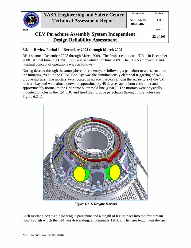
approximately normal to the CM conic outer mold line (OML). The mortars were physically
mounted to holes in the CM FBC and fired their drogue parachutes through those holes (see
Figure 6.3-1).
Figure 6.3-1. Drogue Mortars
Each mortar ejected a single drogue parachute and a length of textile riser into the free stream
flow through which the CM was descending, at nominally 120 f/s. The riser length was the first

NASA Engineering and Safety Center
Technical Assessment Report
Document #:
NESC-RP-
08-00487
Version:
1.0
Title:
CEV Parachute Assembly System Independent
Design Reliability Assessment
Page #:
23 of 109
NESC Request No.: TI-08-00487
item out of a mortar, followed by the packed drogue parachute and then the mortar sabot. Both
risers were attached to a single drogue confluence fitting. Attached to the drogue confluence
fitting, in addition to the two drogue risers, were three textile harness legs. The opposite end of
each drogue harness leg was attached to a fitting on the CM FBC. The three attach fittings were
120 degrees apart. Drogue riser loads were reacted to the CM through the FBC. The three
harness legs and the drogue confluence fitting were stowed in recessed circumferential cavities
on top of the FBC, along with remaining lengths of drogue riser, covered with thermal protection
system (TPS) material (see Figure 6.3-2).
Figure 6.3-2. Drogue Harness Legs and Confluence Fitting Stowed
In the Con Ops for this architecture, each mortar-ejected drogue parachute would begin to open
as it reached ‗line stretch,‘ when its riser and suspension lines are fully deployed (see
Figure 6.3-3). After this point, the drogue parachutes would dis-reef twice to their full-open
position, using redundant reefing line cutters. The drogue parachute canopies were conical
canopy ribbon parachutes with a nominal diameter of 23 ft. They had a continuous 2.0-in.-wide
ribbon with one splice per ribbon and no more than two splices on any one gore.

NASA Engineering and Safety Center
Technical Assessment Report
Document #:
NESC-RP-
08-00487
Version:
1.0
Title:
CEV Parachute Assembly System Independent
Design Reliability Assessment
Page #:
24 of 109
NESC Request No.: TI-08-00487
Figure 6.3-3. Drogue Parachutes
At a preprogrammed, sensed altitude, the FBC would be mechanically released from the CM and
the CM would fall away from the drogue-suspended FBC. In this way the drogue parachutes
provided the forces required to separate the FBC from the CM.
Each of the three main parachutes was packed in its own protective deployment bag (d-bag).
The three main d-bags were restrained with textile straps to the CM upper deck, one in each of
three of the six sectors of the CM forward bay. The stowed arrangement of the three d-bags was
asymmetric. The upper surface of the main d-bags was loosely attached by textile straps to the
underside of the FBC, at points beneath the drogue attach points. Energy-modulating textile
devices were incorporated into these straps to dissipate snatch loads that would result when the
CM rapidly fell away from the decelerated FBC.
In this architecture, the main parachute suspension lines and portions of their risers were also
stowed inside the main d-bags. The bottom ends of the three main risers were attached to a
NASA Engineering and Safety Center
Technical Assessment Report
Document #:
NESC-RP-
08-00487
Version:
1.0
Title:
CEV Parachute Assembly System Independent
Design Reliability Assessment
Page #:
25 of 109
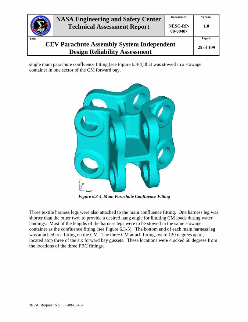
NESC Request No.: TI-08-00487
single main parachute confluence fitting (see Figure 6.3-4) that was stowed in a stowage
container in one sector of the CM forward bay.
Figure 6.3-4. Main Parachute Confluence Fitting
Three textile harness legs were also attached to the main confluence fitting. One harness leg was
shorter than the other two, to provide a desired hang angle for limiting CM loads during water
landings. Most of the lengths of the harness legs were to be stowed in the same stowage
container as the confluence fitting (see Figure 6.3-5). The bottom end of each main harness leg
was attached to a fitting on the CM. The three CM attach fittings were 120 degrees apart,
located atop three of the six forward bay gussets. These locations were clocked 60 degrees from
the locations of the three FBC fittings.

NASA Engineering and Safety Center
Technical Assessment Report
Document #:
NESC-RP-
08-00487
Version:
1.0
Title:
CEV Parachute Assembly System Independent
Design Reliability Assessment
Page #:
26 of 109
NESC Request No.: TI-08-00487
Figure 6.3-5. Main Parachute Packs Stowed
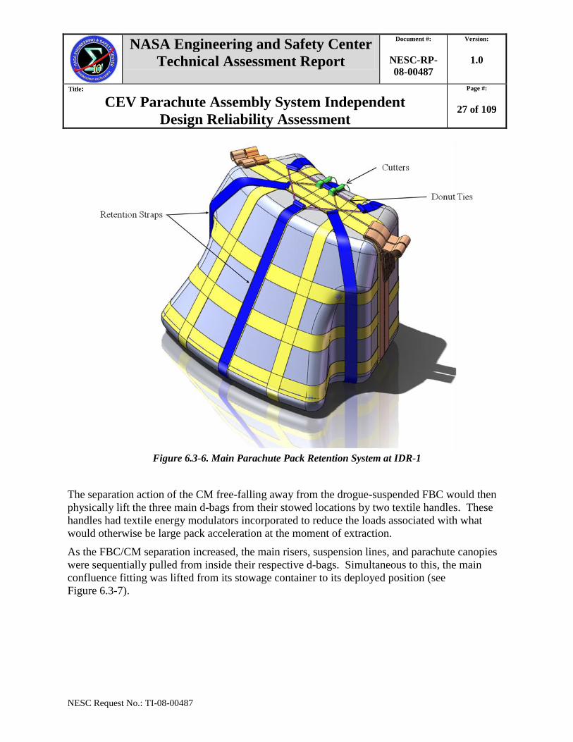
As the CM was released from the monolithic FBC, two redundant donut ties attached at the ends
of six Kevlar® retention straps were to be cut by redundant, electrically commanded cutters (see
Figure 6.3-6).
NASA Engineering and Safety Center
Technical Assessment Report
Document #:
NESC-RP-
08-00487
Version:
1.0
Title:
CEV Parachute Assembly System Independent
Design Reliability Assessment
Page #:
27 of 109
NESC Request No.: TI-08-00487
Figure 6.3-6. Main Parachute Pack Retention System at IDR-1
The separation action of the CM free-falling away from the drogue-suspended FBC would then
physically lift the three main d-bags from their stowed locations by two textile handles. These
handles had textile energy modulators incorporated to reduce the loads associated with what
would otherwise be large pack acceleration at the moment of extraction.
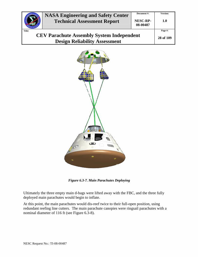
As the FBC/CM separation increased, the main risers, suspension lines, and parachute canopies
were sequentially pulled from inside their respective d-bags. Simultaneous to this, the main
confluence fitting was lifted from its stowage container to its deployed position (see
Figure 6.3-7).
NASA Engineering and Safety Center
Technical Assessment Report
Document #:
NESC-RP-
08-00487
Version:
1.0
Title:
CEV Parachute Assembly System Independent
Design Reliability Assessment
Page #:
28 of 109
NESC Request No.: TI-08-00487
Figure 6.3-7. Main Parachutes Deploying
Ultimately the three empty main d-bags were lifted away with the FBC, and the three fully
deployed main parachutes would begin to inflate.
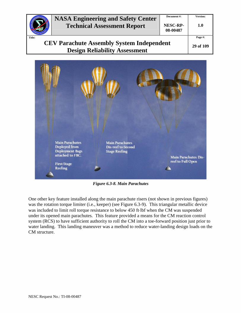
At this point, the main parachutes would dis-reef twice to their full-open position, using
redundant reefing line cutters. The main parachute canopies were ringsail parachutes with a
nominal diameter of 116 ft (see Figure 6.3-8).
NASA Engineering and Safety Center
Technical Assessment Report
Document #:
NESC-RP-
08-00487
Version:
1.0
Title:
CEV Parachute Assembly System Independent
Design Reliability Assessment
Page #:
29 of 109
NESC Request No.: TI-08-00487
Figure 6.3-8. Main Parachutes
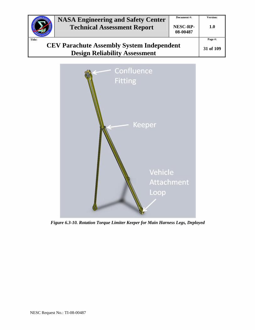
One other key feature installed along the main parachute risers (not shown in previous figures)
was the rotation torque limiter (i.e., keeper) (see Figure 6.3-9). This triangular metallic device
was included to limit roll torque resistance to below 450 ftlbf when the CM was suspended
under its opened main parachutes. This feature provided a means for the CM reaction control
system (RCS) to have sufficient authority to roll the CM into a toe-forward position just prior to
water landing. This landing maneuver was a method to reduce water-landing design loads on the
CM structure.

NASA Engineering and Safety Center
Technical Assessment Report
Document #:
NESC-RP-
08-00487
Version:
1.0
Title:
CEV Parachute Assembly System Independent
Design Reliability Assessment
Page #:
30 of 109
NESC Request No.: TI-08-00487
Figure 6.3-9. Rotation Torque Limiter Keeper for Main Harness Legs
For this architecture, the keeper was to be stowed in a bag in the forward bay, secured alongside
the gusset between the two drogue mortars. The three main harness legs were rigged to pass
through the keeper. When the three main parachutes were deployed, the keeper was held by
straps at a position about 6 ft beneath the confluence fitting. This would provide a 6-ft section of
gathered, parallel harness legs between the confluence fitting and the keeper. This section of
gathered harnesses was envisioned to ‗twist up‘ and ‗untwist‘ in operation, in response to
commands from RCS rockets (see Figures 6.3-10 and 6.3-11).
NASA Engineering and Safety Center
Technical Assessment Report
Document #:
NESC-RP-
08-00487
Version:
1.0
Title:
CEV Parachute Assembly System Independent
Design Reliability Assessment
Page #:
31 of 109
NESC Request No.: TI-08-00487
Figure 6.3-10. Rotation Torque Limiter Keeper for Main Harness Legs, Deployed
NASA Engineering and Safety Center
Technical Assessment Report
Document #:
NESC-RP-
08-00487
Version:
1.0
Title:
CEV Parachute Assembly System Independent
Design Reliability Assessment
Page #:
32 of 109
NESC Request No.: TI-08-00487
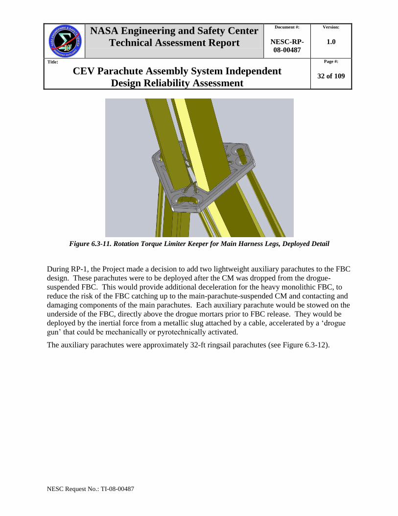
Figure 6.3-11. Rotation Torque Limiter Keeper for Main Harness Legs, Deployed Detail
During RP-1, the Project made a decision to add two lightweight auxiliary parachutes to the FBC
design. These parachutes were to be deployed after the CM was dropped from the drogue-
suspended FBC. This would provide additional deceleration for the heavy monolithic FBC, to
reduce the risk of the FBC catching up to the main-parachute-suspended CM and contacting and
damaging components of the main parachutes. Each auxiliary parachute would be stowed on the
underside of the FBC, directly above the drogue mortars prior to FBC release. They would be
deployed by the inertial force from a metallic slug attached by a cable, accelerated by a ‗drogue
gun‘ that could be mechanically or pyrotechnically activated.
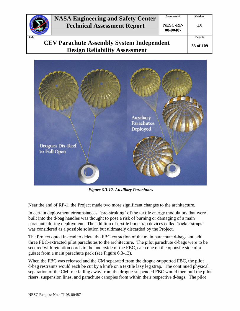
The auxiliary parachutes were approximately 32-ft ringsail parachutes (see Figure 6.3-12).
NASA Engineering and Safety Center
Technical Assessment Report
Document #:
NESC-RP-
08-00487
Version:
1.0
Title:
CEV Parachute Assembly System Independent
Design Reliability Assessment
Page #:
33 of 109
NESC Request No.: TI-08-00487
Figure 6.3-12. Auxiliary Parachutes
Near the end of RP-1, the Project made two more significant changes to the architecture.
In certain deployment circumstances, ‗pre-stroking‘ of the textile energy modulators that were
built into the d-bag handles was thought to pose a risk of burning or damaging of a main
parachute during deployment. The addition of textile bootstrap devices called ‗kicker straps‘
was considered as a possible solution but ultimately discarded by the Project.
The Project opted instead to delete the FBC extraction of the main parachute d-bags and add
three FBC-extracted pilot parachutes to the architecture. The pilot parachute d-bags were to be
secured with retention cords to the underside of the FBC, each one on the opposite side of a
gusset from a main parachute pack (see Figure 6.3-13).
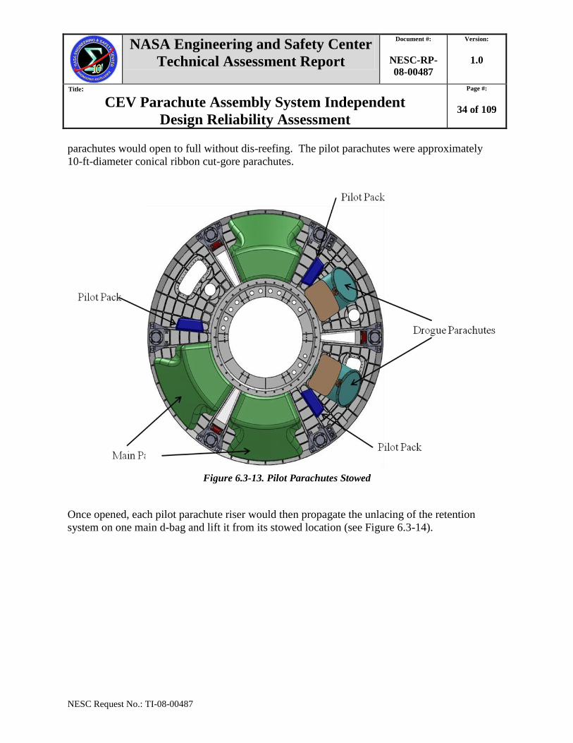
When the FBC was released and the CM separated from the drogue-supported FBC, the pilot
d-bag restraints would each be cut by a knife on a textile lazy leg strap. The continued physical
separation of the CM free falling away from the drogue-suspended FBC would then pull the pilot
risers, suspension lines, and parachute canopies from within their respective d-bags. The pilot
NASA Engineering and Safety Center
Technical Assessment Report
Document #:
NESC-RP-
08-00487
Version:
1.0
Title:
CEV Parachute Assembly System Independent
Design Reliability Assessment
Page #:
34 of 109
NESC Request No.: TI-08-00487
parachutes would open to full without dis-reefing. The pilot parachutes were approximately
10-ft-diameter conical ribbon cut-gore parachutes.
Figure 6.3-13. Pilot Parachutes Stowed
Once opened, each pilot parachute riser would then propagate the unlacing of the retention
system on one main d-bag and lift it from its stowed location (see Figure 6.3-14).

NASA Engineering and Safety Center
Technical Assessment Report
Document #:
NESC-RP-
08-00487
Version:
1.0
Title:
CEV Parachute Assembly System Independent
Design Reliability Assessment
Page #:
35 of 109
NESC Request No.: TI-08-00487
Figure 6.3-14. Pilot Parachutes Deployed
The Project also replaced the single drogue confluence fitting with two individual drogue
confluence rings. The metallic rings would be stowed, one each, inside the drogue mortars on
top of the drogue parachutes and risers. With this change, three textile harness legs were
NASA Engineering and Safety Center
Technical Assessment Report
Document #:
NESC-RP-
08-00487
Version:
1.0
Title:
CEV Parachute Assembly System Independent
Design Reliability Assessment
Page #:
36 of 109
NESC Request No.: TI-08-00487
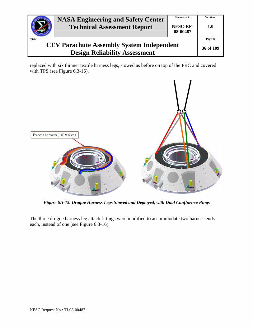
replaced with six thinner textile harness legs, stowed as before on top of the FBC and covered
with TPS (see Figure 6.3-15).
Figure 6.3-15. Drogue Harness Legs Stowed and Deployed, with Dual Confluence Rings
The three drogue harness leg attach fittings were modified to accommodate two harness ends
each, instead of one (see Figure 6.3-16).

NASA Engineering and Safety Center
Technical Assessment Report
Document #:
NESC-RP-
08-00487
Version:
1.0
Title:
CEV Parachute Assembly System Independent
Design Reliability Assessment
Page #:
37 of 109
NESC Request No.: TI-08-00487
Figure 6.3-16. Drogue Harness Leg Attachment Fittings Detail
6.3.2 Review Period 2—April 2009 through August 2009
RP-2 spanned April 2009 through August 2009. Early in this period the CPAS PDR was
rescheduled from June to September 2009.
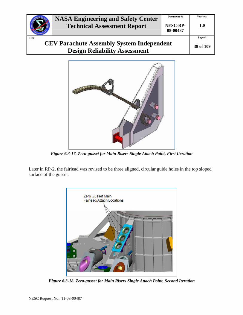
Early during RP-2, the Project changed the attachment scheme for the main parachutes. The
main parachute confluence fitting and the three main parachute harness legs were eliminated.
The three main risers were lengthened accordingly and their ends were all three to be attached to
the ―zero-‖ gusset (i.e., the CM forward bay gusset that was between the two drogue mortars).
The riser fairlead (i.e., the riser guide integrated into the gusset) was first envisioned as a
triangular hole of similar geometry as the keeper in the top sloped surface of the gusset (see
Figures 6.3-17 and 6.3-18).
NASA Engineering and Safety Center
Technical Assessment Report
Document #:
NESC-RP-
08-00487
Version:
1.0
Title:
CEV Parachute Assembly System Independent
Design Reliability Assessment
Page #:
38 of 109
NESC Request No.: TI-08-00487
Figure 6.3-17. Zero-gusset for Main Risers Single Attach Point, First Iteration
Later in RP-2, the fairlead was revised to be three aligned, circular guide holes in the top sloped
surface of the gusset.
Figure 6.3-18. Zero-gusset for Main Risers Single Attach Point, Second Iteration
NASA Engineering and Safety Center
Technical Assessment Report
Document #:
NESC-RP-
08-00487
Version:
1.0
Title:
CEV Parachute Assembly System Independent
Design Reliability Assessment
Page #:
39 of 109
NESC Request No.: TI-08-00487
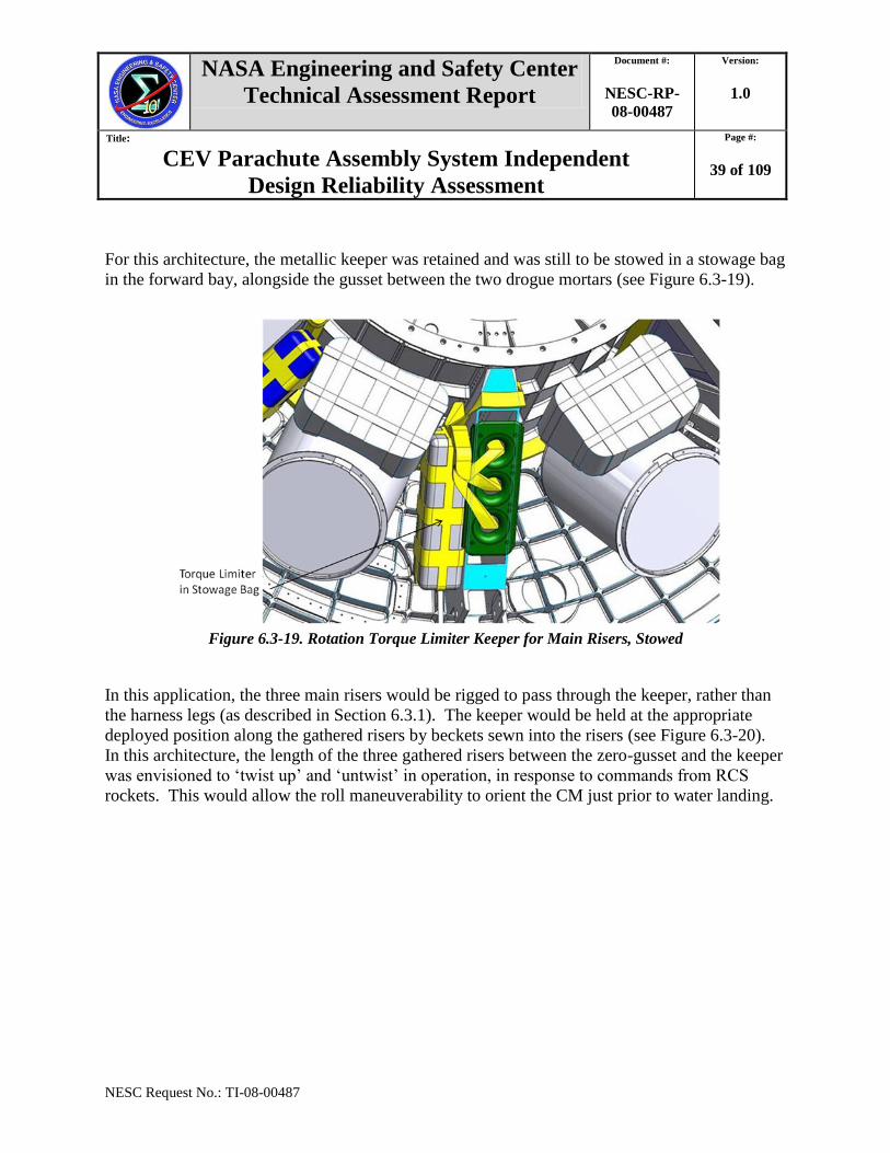
For this architecture, the metallic keeper was retained and was still to be stowed in a stowage bag
in the forward bay, alongside the gusset between the two drogue mortars (see Figure 6.3-19).
Figure 6.3-19. Rotation Torque Limiter Keeper for Main Risers, Stowed
In this application, the three main risers would be rigged to pass through the keeper, rather than
the harness legs (as described in Section 6.3.1). The keeper would be held at the appropriate
deployed position along the gathered risers by beckets sewn into the risers (see Figure 6.3-20).
In this architecture, the length of the three gathered risers between the zero-gusset and the keeper
was envisioned to ‗twist up‘ and ‗untwist‘ in operation, in response to commands from RCS
rockets. This would allow the roll maneuverability to orient the CM just prior to water landing.

NASA Engineering and Safety Center
Technical Assessment Report
Document #:
NESC-RP-
08-00487
Version:
1.0
Title:
CEV Parachute Assembly System Independent
Design Reliability Assessment
Page #:
40 of 109
NESC Request No.: TI-08-00487
Figure 6.3-20. Rotation Torque Limiter Keeper for Main Risers, Deployed Detail
The Project conducted IDR-2 in May 2009, at which several additional architectural
modifications were identified, including revision of the main parachute d-bag shape and the main
d-bag retention and release system. Each main d-bag would be held in place by an upper and a
lower textile retention panel. Each panel interfaced with the d-bag along one outer edge, using a
daisy-chain lacing feature that had heritage design in the Apollo Program ELS main parachute
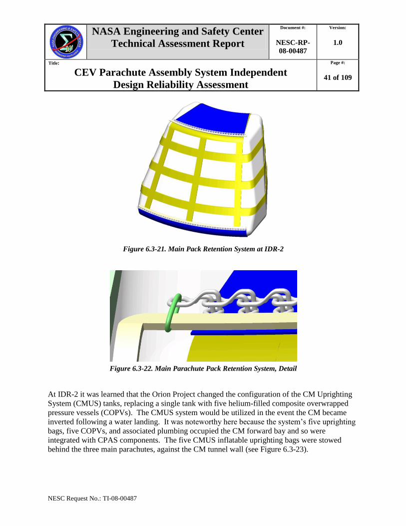
daisy-chain retention system (see Figures 6.3-21 and 6.3-22).
NASA Engineering and Safety Center
Technical Assessment Report
Document #:
NESC-RP-
08-00487
Version:
1.0
Title:
CEV Parachute Assembly System Independent
Design Reliability Assessment
Page #:
41 of 109
NESC Request No.: TI-08-00487
Figure 6.3-21. Main Pack Retention System at IDR-2
Figure 6.3-22. Main Parachute Pack Retention System, Detail
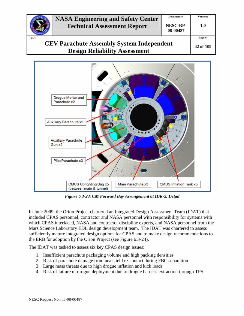
At IDR-2 it was learned that the Orion Project changed the configuration of the CM Uprighting
System (CMUS) tanks, replacing a single tank with five helium-filled composite overwrapped
pressure vessels (COPVs). The CMUS system would be utilized in the event the CM became
inverted following a water landing. It was noteworthy here because the system‘s five uprighting
bags, five COPVs, and associated plumbing occupied the CM forward bay and so were
integrated with CPAS components. The five CMUS inflatable uprighting bags were stowed
behind the three main parachutes, against the CM tunnel wall (see Figure 6.3-23).
NASA Engineering and Safety Center
Technical Assessment Report
Document #:
NESC-RP-
08-00487
Version:
1.0
Title:
CEV Parachute Assembly System Independent
Design Reliability Assessment
Page #:
42 of 109
NESC Request No.: TI-08-00487
Figure 6.3-23. CM Forward Bay Arrangement at IDR-2, Detail
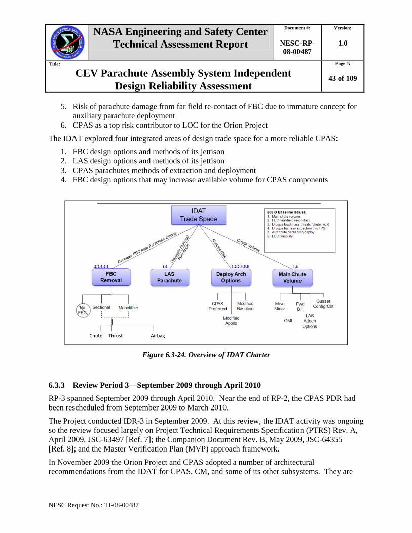
In June 2009, the Orion Project chartered an Integrated Design Assessment Team (IDAT) that
included CPAS personnel, contractor and NASA personnel with responsibility for systems with
which CPAS interfaced, NASA and contractor discipline experts, and NASA personnel from the
Mars Science Laboratory EDL design development team. The IDAT was chartered to assess
sufficiently mature integrated design options for CPAS and to make design recommendations to
the ERB for adoption by the Orion Project (see Figure 6.3-24).
The IDAT was tasked to assess six key CPAS design issues:
1. Insufficient parachute packaging volume and high packing densities
2. Risk of parachute damage from near field re-contact during FBC separation
3. Large mass threats due to high drogue inflation and kick loads
4. Risk of failure of drogue deployment due to drogue harness extraction through TPS
NASA Engineering and Safety Center
Technical Assessment Report
Document #:
NESC-RP-
08-00487
Version:
1.0
Title:
CEV Parachute Assembly System Independent
Design Reliability Assessment
Page #:
43 of 109
NESC Request No.: TI-08-00487
5. Risk of parachute damage from far field re-contact of FBC due to immature concept for
auxiliary parachute deployment
6. CPAS as a top risk contributor to LOC for the Orion Project
The IDAT explored four integrated areas of design trade space for a more reliable CPAS:
1. FBC design options and methods of its jettison
2. LAS design options and methods of its jettison
3. CPAS parachutes methods of extraction and deployment
4. FBC design options that may increase available volume for CPAS components
Figure 6.3-24. Overview of IDAT Charter
6.3.3 Review Period 3—September 2009 through April 2010
RP-3 spanned September 2009 through April 2010. Near the end of RP-2, the CPAS PDR had
been rescheduled from September 2009 to March 2010.
The Project conducted IDR-3 in September 2009. At this review, the IDAT activity was ongoing
so the review focused largely on Project Technical Requirements Specification (PTRS) Rev. A,
April 2009, JSC-63497 [Ref. 7]; the Companion Document Rev. B, May 2009, JSC-64355
[Ref. 8]; and the Master Verification Plan (MVP) approach framework.
In November 2009 the Orion Project and CPAS adopted a number of architectural
recommendations from the IDAT for CPAS, CM, and some of its other subsystems. They are
NASA Engineering and Safety Center
Technical Assessment Report
Document #:
NESC-RP-
08-00487
Version:
1.0
Title:
CEV Parachute Assembly System Independent
Design Reliability Assessment
Page #:
44 of 109
NESC Request No.: TI-08-00487
described in the following sections, along with additional design refinements incorporated before
April 2010.
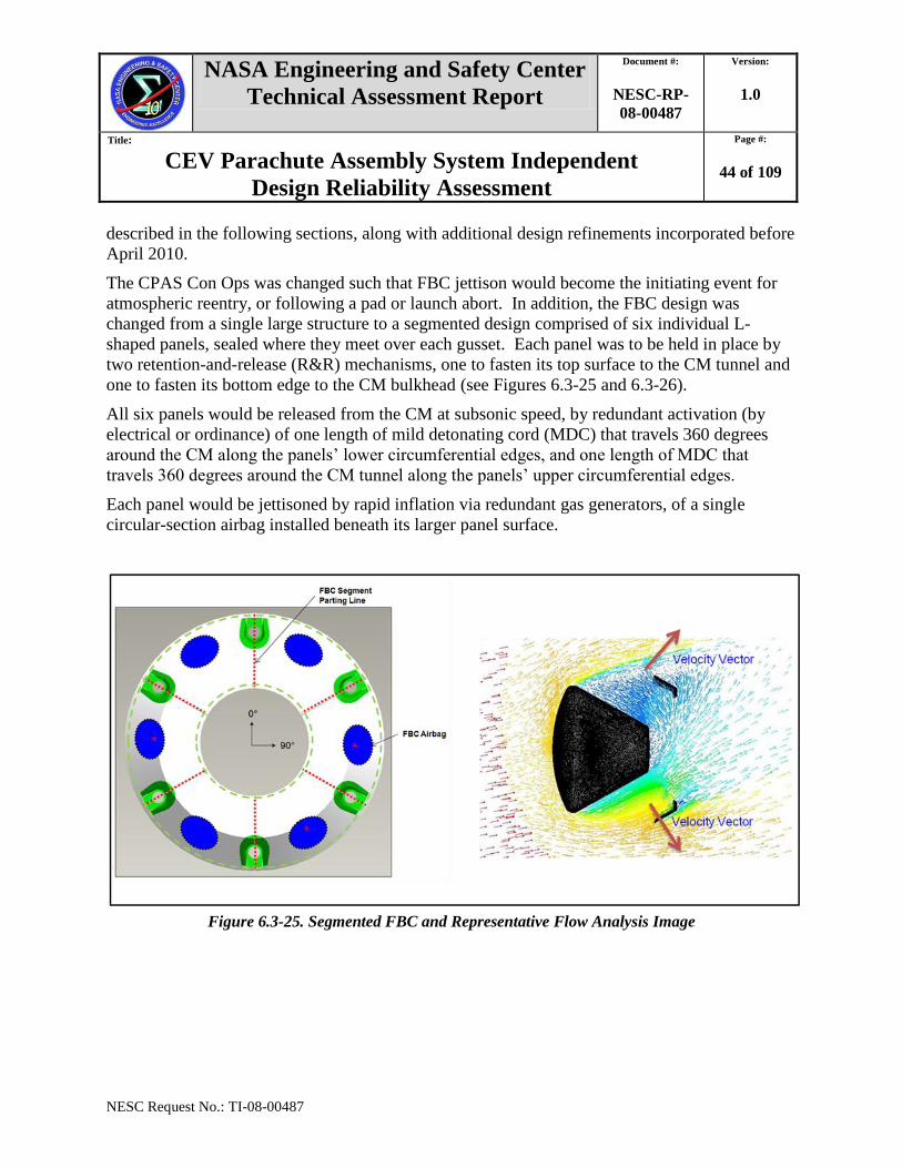
The CPAS Con Ops was changed such that FBC jettison would become the initiating event for
atmospheric reentry, or following a pad or launch abort. In addition, the FBC design was
changed from a single large structure to a segmented design comprised of six individual L-
shaped panels, sealed where they meet over each gusset. Each panel was to be held in place by
two retention-and-release (R&R) mechanisms, one to fasten its top surface to the CM tunnel and
one to fasten its bottom edge to the CM bulkhead (see Figures 6.3-25 and 6.3-26).
All six panels would be released from the CM at subsonic speed, by redundant activation (by
electrical or ordinance) of one length of mild detonating cord (MDC) that travels 360 degrees
around the CM along the panels‘ lower circumferential edges, and one length of MDC that
travels 360 degrees around the CM tunnel along the panels‘ upper circumferential edges.
Each panel would be jettisoned by rapid inflation via redundant gas generators, of a single
circular-section airbag installed beneath its larger panel surface.
Figure 6.3-25. Segmented FBC and Representative Flow Analysis Image
NASA Engineering and Safety Center
Technical Assessment Report
Document #:
NESC-RP-
08-00487
Version:
1.0
Title:
CEV Parachute Assembly System Independent
Design Reliability Assessment
Page #:
45 of 109
NESC Request No.: TI-08-00487
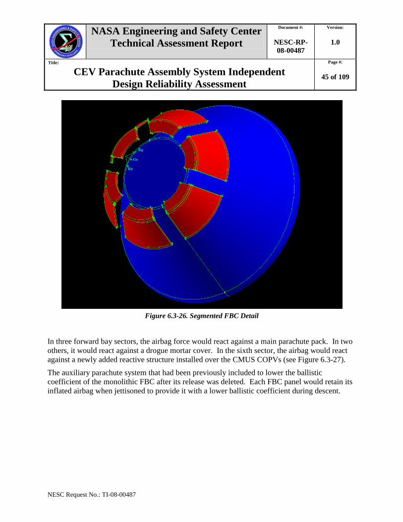
Figure 6.3-26. Segmented FBC Detail
In three forward bay sectors, the airbag force would react against a main parachute pack. In two
others, it would react against a drogue mortar cover. In the sixth sector, the airbag would react
against a newly added reactive structure installed over the CMUS COPVs (see Figure 6.3-27).
The auxiliary parachute system that had been previously included to lower the ballistic
coefficient of the monolithic FBC after its release was deleted. Each FBC panel would retain its
inflated airbag when jettisoned to provide it with a lower ballistic coefficient during descent.
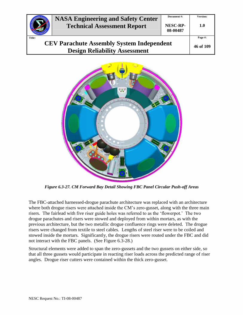
NASA Engineering and Safety Center
Technical Assessment Report
Document #:
NESC-RP-
08-00487
Version:
1.0
Title:
CEV Parachute Assembly System Independent
Design Reliability Assessment
Page #:
46 of 109
NESC Request No.: TI-08-00487
Figure 6.3-27. CM Forward Bay Detail Showing FBC Panel Circular Push-off Areas
The FBC-attached harnessed-drogue parachute architecture was replaced with an architecture
where both drogue risers were attached inside the CM‘s zero-gusset, along with the three main
risers. The fairlead with five riser guide holes was referred to as the ‗flowerpot.‘ The two
drogue parachutes and risers were stowed and deployed from within mortars, as with the
previous architecture, but the two metallic drogue confluence rings were deleted. The drogue
risers were changed from textile to steel cables. Lengths of steel riser were to be coiled and
stowed inside the mortars. Significantly, the drogue risers were routed under the FBC and did
not interact with the FBC panels. (See Figure 6.3-28.)
Structural elements were added to span the zero-gussets and the two gussets on either side, so
that all three gussets would participate in reacting riser loads across the predicted range of riser
angles. Drogue riser cutters were contained within the thick zero-gusset.
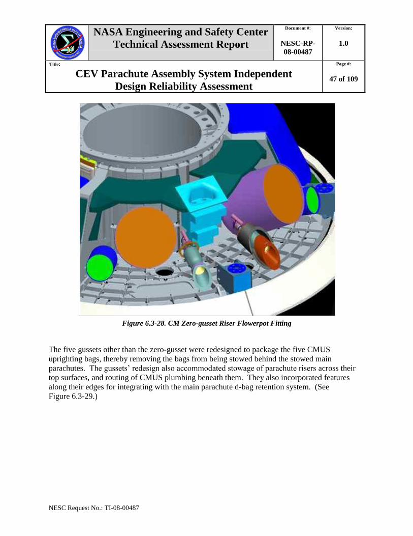
NASA Engineering and Safety Center
Technical Assessment Report
Document #:
NESC-RP-
08-00487
Version:
1.0
Title:
CEV Parachute Assembly System Independent
Design Reliability Assessment
Page #:
47 of 109
NESC Request No.: TI-08-00487
Figure 6.3-28. CM Zero-gusset Riser Flowerpot Fitting
The five gussets other than the zero-gusset were redesigned to package the five CMUS
uprighting bags, thereby removing the bags from being stowed behind the stowed main
parachutes. The gussets‘ redesign also accommodated stowage of parachute risers across their
top surfaces, and routing of CMUS plumbing beneath them. They also incorporated features
along their edges for integrating with the main parachute d-bag retention system. (See
Figure 6.3-29.)
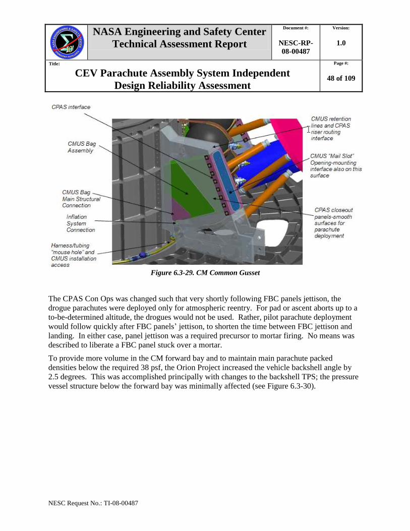
NASA Engineering and Safety Center
Technical Assessment Report
Document #:
NESC-RP-
08-00487
Version:
1.0
Title:
CEV Parachute Assembly System Independent
Design Reliability Assessment
Page #:
48 of 109
NESC Request No.: TI-08-00487
Figure 6.3-29. CM Common Gusset
The CPAS Con Ops was changed such that very shortly following FBC panels jettison, the
drogue parachutes were deployed only for atmospheric reentry. For pad or ascent aborts up to a
to-be-determined altitude, the drogues would not be used. Rather, pilot parachute deployment
would follow quickly after FBC panels‘ jettison, to shorten the time between FBC jettison and
landing. In either case, panel jettison was a required precursor to mortar firing. No means was
described to liberate a FBC panel stuck over a mortar.
To provide more volume in the CM forward bay and to maintain main parachute packed
densities below the required 38 psf, the Orion Project increased the vehicle backshell angle by
2.5 degrees. This was accomplished principally with changes to the backshell TPS; the pressure
vessel structure below the forward bay was minimally affected (see Figure 6.3-30).
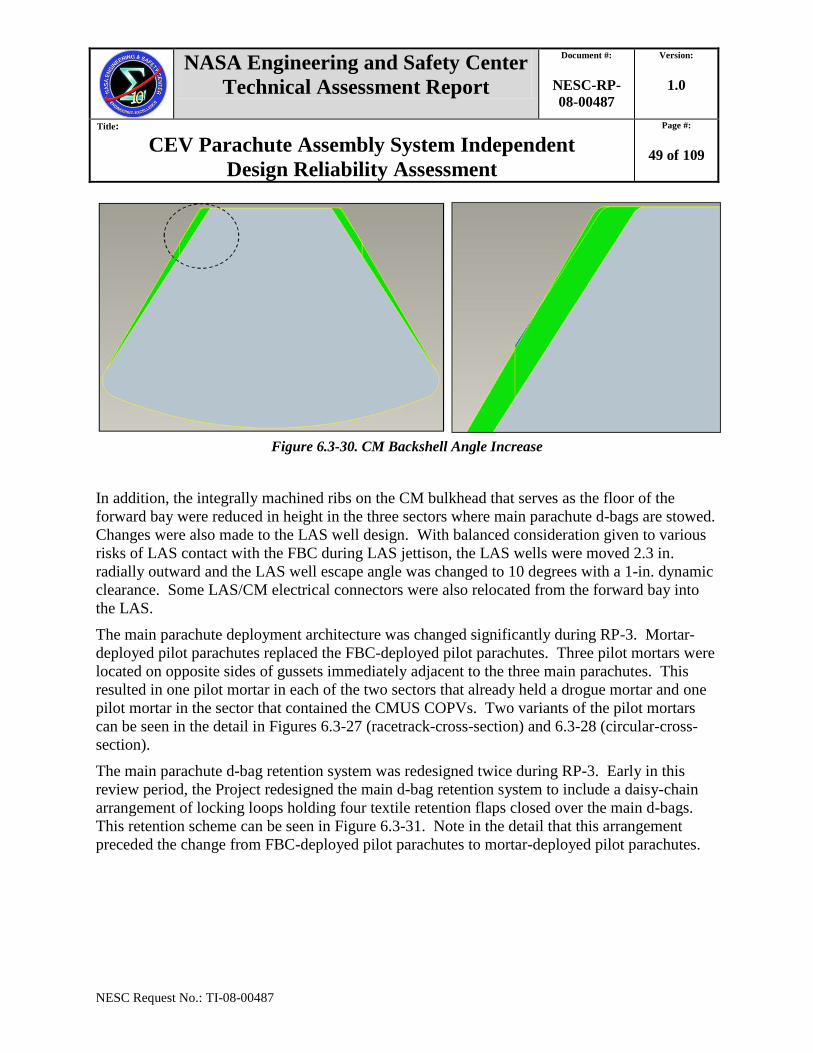
NASA Engineering and Safety Center
Technical Assessment Report
Document #:
NESC-RP-
08-00487
Version:
1.0
Title:
CEV Parachute Assembly System Independent
Design Reliability Assessment
Page #:
49 of 109
NESC Request No.: TI-08-00487
Figure 6.3-30. CM Backshell Angle Increase
In addition, the integrally machined ribs on the CM bulkhead that serves as the floor of the
forward bay were reduced in height in the three sectors where main parachute d-bags are stowed.
Changes were also made to the LAS well design. With balanced consideration given to various
risks of LAS contact with the FBC during LAS jettison, the LAS wells were moved 2.3 in.
radially outward and the LAS well escape angle was changed to 10 degrees with a 1-in. dynamic
clearance. Some LAS/CM electrical connectors were also relocated from the forward bay into
the LAS.
The main parachute deployment architecture was changed significantly during RP-3. Mortar-
deployed pilot parachutes replaced the FBC-deployed pilot parachutes. Three pilot mortars were
located on opposite sides of gussets immediately adjacent to the three main parachutes. This
resulted in one pilot mortar in each of the two sectors that already held a drogue mortar and one
pilot mortar in the sector that contained the CMUS COPVs. Two variants of the pilot mortars
can be seen in the detail in Figures 6.3-27 (racetrack-cross-section) and 6.3-28 (circular-cross-
section).
The main parachute d-bag retention system was redesigned twice during RP-3. Early in this
review period, the Project redesigned the main d-bag retention system to include a daisy-chain
arrangement of locking loops holding four textile retention flaps closed over the main d-bags.
This retention scheme can be seen in Figure 6.3-31. Note in the detail that this arrangement
preceded the change from FBC-deployed pilot parachutes to mortar-deployed pilot parachutes.
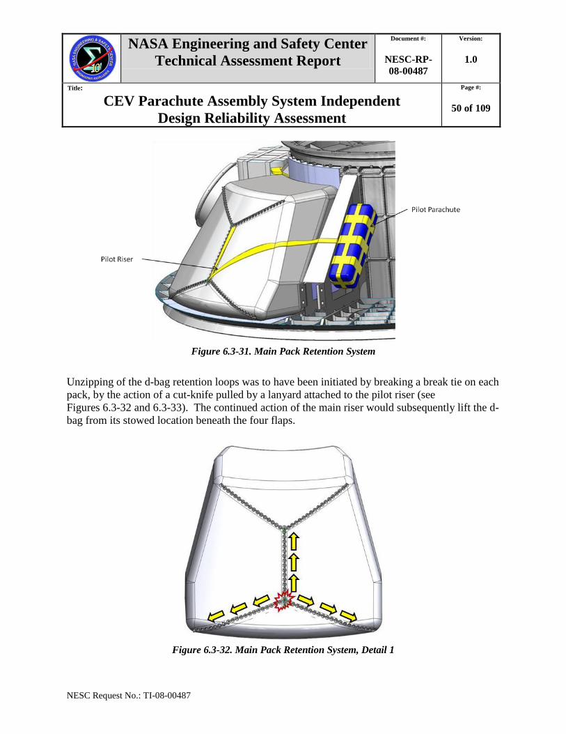
NASA Engineering and Safety Center
Technical Assessment Report
Document #:
NESC-RP-
08-00487
Version:
1.0
Title:
CEV Parachute Assembly System Independent
Design Reliability Assessment
Page #:
50 of 109
NESC Request No.: TI-08-00487
Figure 6.3-31. Main Pack Retention System
Unzipping of the d-bag retention loops was to have been initiated by breaking a break tie on each
pack, by the action of a cut-knife pulled by a lanyard attached to the pilot riser (see
Figures 6.3-32 and 6.3-33). The continued action of the main riser would subsequently lift the d-
bag from its stowed location beneath the four flaps.
Figure 6.3-32. Main Pack Retention System, Detail 1
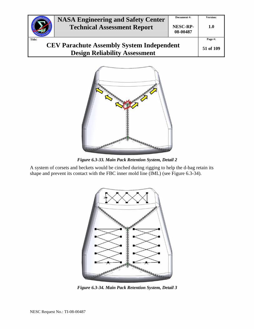
NASA Engineering and Safety Center
Technical Assessment Report
Document #:
NESC-RP-
08-00487
Version:
1.0
Title:
CEV Parachute Assembly System Independent
Design Reliability Assessment
Page #:
51 of 109
NESC Request No.: TI-08-00487
Figure 6.3-33. Main Pack Retention System, Detail 2
A system of corsets and beckets would be cinched during rigging to help the d-bag retain its
shape and prevent its contact with the FBC inner mold line (IML) (see Figure 6.3-34).
Figure 6.3-34. Main Pack Retention System, Detail 3
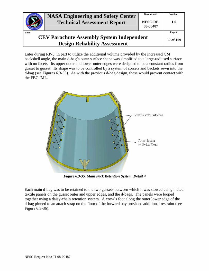
NASA Engineering and Safety Center
Technical Assessment Report
Document #:
NESC-RP-
08-00487
Version:
1.0
Title:
CEV Parachute Assembly System Independent
Design Reliability Assessment
Page #:
52 of 109
NESC Request No.: TI-08-00487
Later during RP-3, in part to utilize the additional volume provided by the increased CM
backshell angle, the main d-bag‘s outer surface shape was simplified to a large-radiused surface
with no facets. Its upper outer and lower outer edges were designed to be a constant radius from
gusset to gusset. Its shape was to be controlled by a system of corsets and beckets sewn into the
d-bag (see Figures 6.3-35). As with the previous d-bag design, these would prevent contact with
the FBC IML.
Figure 6.3-35. Main Pack Retention System, Detail 4
Each main d-bag was to be retained to the two gussets between which it was stowed using mated
textile panels on the gusset outer and upper edges, and the d-bags. The panels were looped
together using a daisy-chain retention system. A crow‘s foot along the outer lower edge of the
d-bag pinned to an attach strap on the floor of the forward bay provided additional restraint (see
Figure 6.3-36).
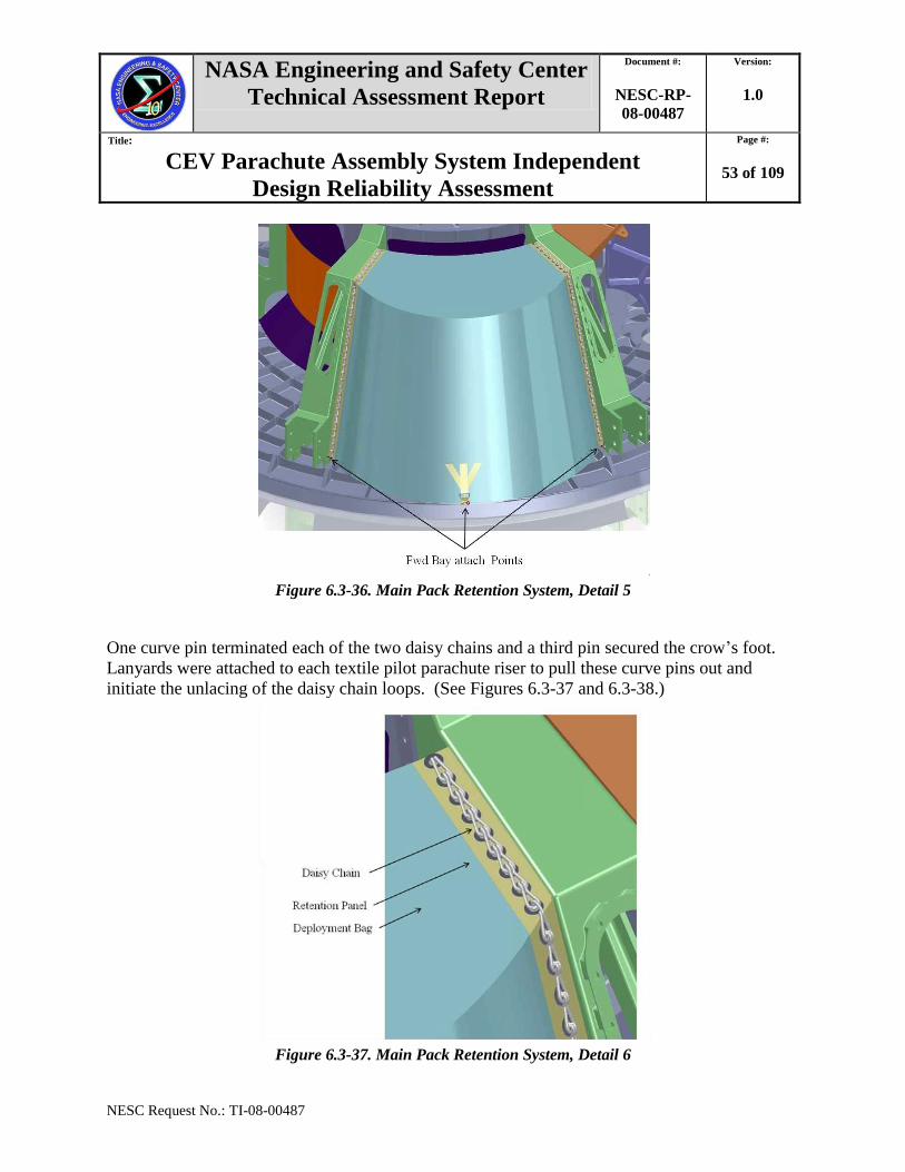
NASA Engineering and Safety Center
Technical Assessment Report
Document #:
NESC-RP-
08-00487
Version:
1.0
Title:
CEV Parachute Assembly System Independent
Design Reliability Assessment
Page #:
53 of 109
NESC Request No.: TI-08-00487
Figure 6.3-36. Main Pack Retention System, Detail 5
One curve pin terminated each of the two daisy chains and a third pin secured the crow‘s foot.
Lanyards were attached to each textile pilot parachute riser to pull these curve pins out and
initiate the unlacing of the daisy chain loops. (See Figures 6.3-37 and 6.3-38.)
Figure 6.3-37. Main Pack Retention System, Detail 6
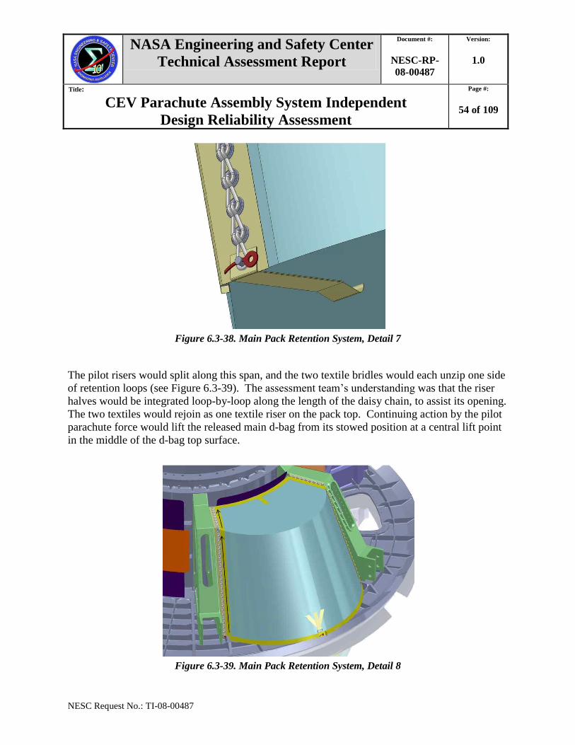
NASA Engineering and Safety Center
Technical Assessment Report
Document #:
NESC-RP-
08-00487
Version:
1.0
Title:
CEV Parachute Assembly System Independent
Design Reliability Assessment
Page #:
54 of 109
NESC Request No.: TI-08-00487
Figure 6.3-38. Main Pack Retention System, Detail 7
The pilot risers would split along this span, and the two textile bridles would each unzip one side
of retention loops (see Figure 6.3-39). The assessment team‘s understanding was that the riser
halves would be integrated loop-by-loop along the length of the daisy chain, to assist its opening.
The two textiles would rejoin as one textile riser on the pack top. Continuing action by the pilot
parachute force would lift the released main d-bag from its stowed position at a central lift point
in the middle of the d-bag top surface.
Figure 6.3-39. Main Pack Retention System, Detail 8
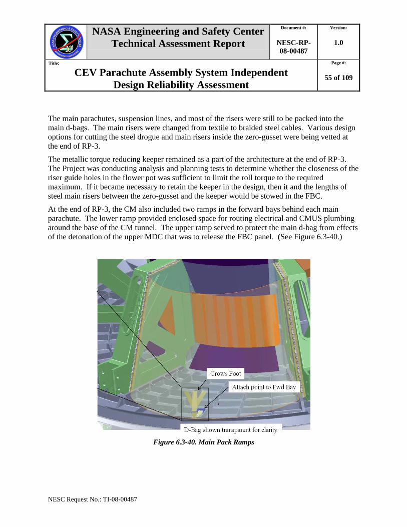
NASA Engineering and Safety Center
Technical Assessment Report
Document #:
NESC-RP-
08-00487
Version:
1.0
Title:
CEV Parachute Assembly System Independent
Design Reliability Assessment
Page #:
55 of 109
NESC Request No.: TI-08-00487
The main parachutes, suspension lines, and most of the risers were still to be packed into the
main d-bags. The main risers were changed from textile to braided steel cables. Various design
options for cutting the steel drogue and main risers inside the zero-gusset were being vetted at
the end of RP-3.
The metallic torque reducing keeper remained as a part of the architecture at the end of RP-3.
The Project was conducting analysis and planning tests to determine whether the closeness of the
riser guide holes in the flower pot was sufficient to limit the roll torque to the required
maximum. If it became necessary to retain the keeper in the design, then it and the lengths of
steel main risers between the zero-gusset and the keeper would be stowed in the FBC.
At the end of RP-3, the CM also included two ramps in the forward bays behind each main
parachute. The lower ramp provided enclosed space for routing electrical and CMUS plumbing
around the base of the CM tunnel. The upper ramp served to protect the main d-bag from effects
of the detonation of the upper MDC that was to release the FBC panel. (See Figure 6.3-40.)
Figure 6.3-40. Main Pack Ramps
NASA Engineering and Safety Center
Technical Assessment Report
Document #:
NESC-RP-
08-00487
Version:
1.0
Title:
CEV Parachute Assembly System Independent
Design Reliability Assessment
Page #:
56 of 109
NESC Request No.: TI-08-00487
6.4 PRA and other Reliability Products
The evolution and refinement of the Project‘s PRA and other reliability information are
described in the following sections.
6.4.1 Review Period 1—December 2008 through March 2009
A preliminary FTA, Hazard Analysis (HA), and PRA were provided at IDR-1. PRA failure
estimates were generated from reliability data obtained from the following sources:
1. Parachute drop data from the U.S. Army, Apollo Program, Soyuz Program, and SSP
SRB.
2. Vendor component data.
3. Component reliability predictions computed from the intersections of material strength
and applied load probability distributions (load-strength interference method).
The Project showed data that SSP SRB parachute contact with its main parachute support system
during extraction had occurred 3 times out of 651 demands (1:217). The CPAS Project assessed
that this data was pertinent to CPAS, equivalent to the CPAS failure mode ―deployment failure
damage due to structural contact.‖ The Project noted that the SSP SRB architecture assured that
only one out of three parachutes could fail by this mode, but that the CPAS architecture at that
time did not preclude multiple parachute contacts with structure. The Project computed system
reliability if only one CPAS main parachute failed by this mechanism to be 1:8,205.
The failure estimate of 1:217 became the driving value in the CPAS PRA. The Project noted that
simulation analyses and ground and flight testing would ultimately refine this failure probability
for the CPAS architecture.
AS provided reliability data at IDR-1 for the drogue and main parachute assemblies. The
reliability of most components had been predicted from the intersections of material strength and
applied load distributions to determine the ―areas of unreliability‖ (from the area of intersection
of the two distributions). (See Tables 6.4-1 and 6.4-2.)
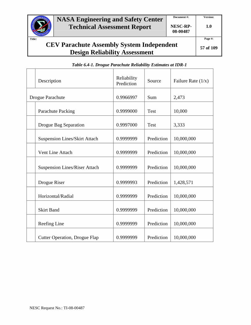
NASA Engineering and Safety Center
Technical Assessment Report
Document #:
NESC-RP-
08-00487
Version:
1.0
Title:
CEV Parachute Assembly System Independent
Design Reliability Assessment
Page #:
57 of 109
NESC Request No.: TI-08-00487
Table 6.4-1. Drogue Parachute Reliability Estimates at IDR-1
Description Reliability
Prediction Source Failure Rate (1/x)
Drogue Parachute 0.9966997 Sum 2,473
Parachute Packing 0.9999000 Test 10,000
Drogue Bag Separation 0.9997000 Test 3,333
Suspension Lines/Skirt Attach 0.9999999 Prediction 10,000,000
Vent Line Attach 0.9999999 Prediction 10,000,000
Suspension Lines/Riser Attach 0.9999999 Prediction 10,000,000
Drogue Riser 0.9999993 Prediction 1,428,571
Horizontal/Radial 0.9999999 Prediction 10,000,000
Skirt Band 0.9999999 Prediction 10,000,000
Reefing Line 0.9999999 Prediction 10,000,000
Cutter Operation, Drogue Flap 0.9999999 Prediction 10,000,000
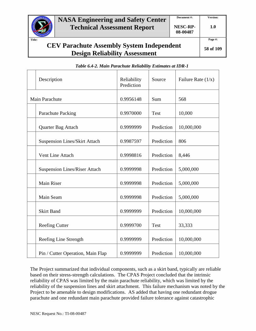
NASA Engineering and Safety Center
Technical Assessment Report
Document #:
NESC-RP-
08-00487
Version:
1.0
Title:
CEV Parachute Assembly System Independent
Design Reliability Assessment
Page #:
58 of 109
NESC Request No.: TI-08-00487
Table 6.4-2. Main Parachute Reliability Estimates at IDR-1
Description Reliability
Prediction
Source Failure Rate (1/x)
Main Parachute 0.9956148 Sum 568
Parachute Packing 0.9970000 Test 10,000
Quarter Bag Attach 0.9999999 Prediction 10,000,000
Suspension Lines/Skirt Attach 0.9987597 Prediction 806
Vent Line Attach 0.9998816 Prediction 8,446
Suspension Lines/Riser Attach 0.9999998 Prediction 5,000,000
Main Riser 0.9999998 Prediction 5,000,000
Main Seam 0.9999998 Prediction 5,000,000
Skirt Band 0.9999999 Prediction 10,000,000
Reefing Cutter 0.9999700 Test 33,333
Reefing Line Strength 0.9999999 Prediction 10,000,000
Pin / Cutter Operation, Main Flap 0.9999999 Prediction 10,000,000
The Project summarized that individual components, such as a skirt band, typically are reliable
based on their stress-strength calculations. The CPAS Project concluded that the intrinsic
reliability of CPAS was limited by the main parachute reliability, which was limited by the
reliability of the suspension lines and skirt attachment. This failure mechanism was noted by the
Project to be amenable to design modifications. AS added that having one redundant drogue
parachute and one redundant main parachute provided failure tolerance against catastrophic

NASA Engineering and Safety Center
Technical Assessment Report
Document #:
NESC-RP-
08-00487
Version:
1.0
Title:
CEV Parachute Assembly System Independent
Design Reliability Assessment
Page #:
59 of 109
NESC Request No.: TI-08-00487
failure, and that the drogue and main parachutes were being designed to survive loading
conditions associated with a skipped reefing stage.
In assessment team discussions during RP-1, reliability subteam members led productive
discussions of reliability budget methods and benefits.
In February 2009, the assessment team conducted a meeting with the Project. The assessment
team provided an advance list of 42 questions to improve its understanding of CPAS, its
function, and associated reliability risks. The assessment team asked questions on the
verification and validation (V&V) of the simulation codes used for design and reliability
decisions, which was declared to be outside the scope of CPAS‘s responsibilities. The Project
satisfactorily answered the assessment team‘s questions.
The same month, the Project briefed the assessment team on two separate versions of CPAS fault
trees (FTs) it was maintaining. A comprehensive FT was being maintained by a NASA civil
servant and simpler FT was being maintained by a Jacobs ESCG counterpart. The latter FT was
to be linked to the evolving PRA. At this meeting the Project noted dashed lines in the FT that
connected to faults key to CPAS reliability but considered administratively outside of CPAS.
These were the responsibilities of developers of other CM subsystems. At this meeting the
Project also identified where additional data still was needed to refine the PRA.
6.4.2 Review Period 2—April 2009 through August 2009
At IDR-2 the Project presented a status summary of its Risk Assessment Executive Summary
Report (RAESR), failure modes and effects analysis (FMEA)/critical items list, FTA, and HA.
These deliverable products were to be completed by the S&MA team prior to the Project‘s PDR.
The PRA was described as a living work product subject to change from testing and analyses
results. Two methods were described in use for determining PRA reliability values: predictions
and estimates. Predictions were described as being based on historical or vendor data. Estimates
were described as being based on expert opinion and engineering judgment (EJ). The Project
indicated intent to conduct an EE exercise.
The Project identified 17 top-level failure modes as CPAS PRA ‗input values‘ for the FTA (see
Table 6.4-3). Thirteen of those were estimated in whole or in part by EJ. Heritage Apollo
Program data had been used to predict some values where available and applicable.

NASA Engineering and Safety Center
Technical Assessment Report
Document #:
NESC-RP-
08-00487
Version:
1.0
Title:
CEV Parachute Assembly System Independent
Design Reliability Assessment
Page #:
60 of 109
NESC Request No.: TI-08-00487
Table 6.4-3. CPAS Input Values for PRA at IDR-2
PRA Input Value Source
1. Drogue Confluence Failure EJ
2. Vibration/Shock/Acceleration EJ
3. Rigging Error EJ
4. Far-Field Contact Computed value, EJ
5. Near-Field Contact EJ
6. Main Chute Entanglement EJ
7. Drogue Chute Entanglement EJ
8. Auxiliary/Auxiliary Chute Entanglement EJ
9. Skipped Reefing State Failure EJ, predicted from Apollo Program data
10. Main Chute Deployment Failure Predicted from Mercury/Gemini/Apollo and
other Missions
11. Auxiliary Chute Deployment Failure EJ
12. Drogue Chute Deployment Failure Predicted from Mercury/Gemini/Apollo
Missions
13. Pilot Chute Deployment Failure EJ
14. Lead Lag Failure EJ
15. Inflation Failure EJ
16. Reefing Cutter Fails to Dis-reef Failure Predicted from Apollo Program data
17. Structural Failure Predicted from material properties
At the IDR-2, reliability values for the 17 input values were presented for the cases of reentry,
pad abort, and ascent abort (see Table 6.4-4).
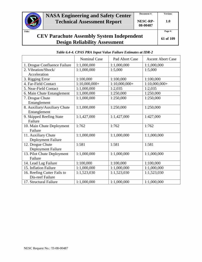
NASA Engineering and Safety Center
Technical Assessment Report
Document #:
NESC-RP-
08-00487
Version:
1.0
Title:
CEV Parachute Assembly System Independent
Design Reliability Assessment
Page #:
61 of 109
NESC Request No.: TI-08-00487
Table 6.4-4. CPAS PRA Input Value Failure Estimates at IDR-2
Nominal Case Pad Abort Case Ascent Abort Case
1. Drogue Confluence Failure 1:1,000,000 1:1,000,000 1:1,000,000
2. Vibration/Shock/
Acceleration
1:1,000,000 1:5,000 1:5,000
3. Rigging Error 1:100,000 1:100,000 1:100,000
4. Far-Field Contact 1:10,000,000+ 1:10,000,000+ 1:10,000,000+
5. Near-Field Contact 1:1,000,000 1:2,035 1:2,035
6. Main Chute Entanglement 1:1,000,000 1:250,000 1:250,000
7. Drogue Chute
Entanglement
1:1,000,000 1:250,000 1:250,000
8. Auxiliary/Auxiliary Chute
Entanglement
1:1,000,000 1:250,000 1:250,000
9. Skipped Reefing State
Failure
1:1,427,000 1:1,427,000 1:427,000
10. Main Chute Deployment
Failure
1:762 1:762 1:762
11. Auxiliary Chute
Deployment Failure
1:1,000,000 1:1,000,000 1:1,000,000
12. Drogue Chute
Deployment Failure
1:581 1:581 1:581
13. Pilot Chute Deployment
Failure
1:1,000,000 1:1,000,000 1:1,000,000
14. Lead Lag Failure 1:100,000 1:100,000 1:100,000
15. Inflation Failure 1:1,000,000 1:1,000,000 1:1,000,000
16. Reefing Cutter Fails to
Dis-reef Failure
1:1,523,030 1:1,523,030 1:1,523,030
17. Structural Failure 1:1,000,000 1:1,000,000 1:1,000,000

NASA Engineering and Safety Center
Technical Assessment Report
Document #:
NESC-RP-
08-00487
Version:
1.0
Title:
CEV Parachute Assembly System Independent
Design Reliability Assessment
Page #:
62 of 109
NESC Request No.: TI-08-00487
The top-level estimated reliability for the cases of reentry, pad abort, or ascent abort was also
presented at IDR-2 (see Table 6.4-5). The estimates were less than the objective CPAS LOC
target of 1:2,500.
Table 6.4-5. CPAS PRA at IDR-2
Mean 95% Confidence
Nominal Reentry 1:9,502 1:2,397
Pad Abort 1:6,045 1:2,016
Ascent Abort 1:6,097 1:2,065
During RP-2, the Project conducted an EE exercise to attempt to improve the failure and
uncertainty estimates for their input values. Two of the NESC parachute design and
development subteam members participated as individual experts (not as representatives of the
chartered assessment team). Their participation involved writing answers to a Project-developed
questionnaire.
6.4.3 Review Period 3—September 2009 through April 2010
During RP-3, the target for LOC for CPAS remained 1:2,500. The target for the LRS was 1:850
for the then-current Orion design variant 606G. Recall that the LRS included CPAS plus drogue
and pilot mortars, riser cutters, the fairlead fitting, NSIs, auxiliary parachute guns (if included in
the design), and the CMUS.
The Project provided copies of the FTA, HA, FMEA, and PRA to the assessment team at IDR-3.
The HA and FMEA had been updated significantly. The latter now listed the ‗Crit-1‘ main riser
torque-reducing keeper as a candidate design for minimum risk (DFMR) component.
The CPAS Reliability and Maintainability Report was shown to describe the Project‘s reliability
determination methods as described previously at IDR-2:
Reliability Estimations: Expert opinion and EJ were used to determine reliability
estimates.
Reliability Predictions: Based on historical or vendor data; examines previous reliability
data collected on other Projects in order to predict component/system reliability for the
activity under examination.
The Project reported that based on reliability predictions from previous generation vehicles and
expert opinion and the EJ of Project personnel and AS personnel, the top LOC estimate for
nominal entry was 1:9,494. This was consistent with the mean value reported at IDR-2.
NASA Engineering and Safety Center
Technical Assessment Report
Document #:
NESC-RP-
08-00487
Version:
1.0
Title:
CEV Parachute Assembly System Independent
Design Reliability Assessment
Page #:
63 of 109
NESC Request No.: TI-08-00487
The Project provided results from its recently completed EE exercise at IDR-3, but these data
had not yet been incorporated into PRA input value estimates. Five experts had participated.
Based on their answers the top system-level CPAS failure probability was estimated to be
1:1040. Failure to deploy a main parachute (PRA input value #10) was estimated to be 1:613 for
the nominal reentry case. [Ref. 9: Expert Elicitation Summary Report for the Crew Exploration
Vehicle (CEV) Parachute Assembly System (CPAS), JSC 64967, ESCG-6110-09-SS-DOC-0744.]
A large variance was reported in the component reliability values. The Project reported that the
experts would be asked to reexamine the resulting estimates as a sanity check.
When the CPAS architecture changes based on IDAT recommendations (described in Section
6.3.3) were adopted in November 2009, the assessment team discussed these and assessed their
impact on system reliability. Near the end of RP-3, the Project indicated an intention to conduct
a ‗delta‘ EE exercise with a revised list of PRA input values that reflected the latest architecture.
6.5 Requirements, Testing, Analyses, and Verification Planning
The evolution and refinement of the Project‘s requirements, testing, analyses, and verification
planning are described in the following sections.
6.5.1 Review Period 1—December 2008 through March 2009
At IDR-1, the draft requirements document, the PTRS [Ref. 7, Baseline version] was provided to
the assessment team for review. A companion document, referred to as the Assumptions
Document [Ref. 8, Rev. A] was also provided. The key driving requirement for CPAS was to
decelerate the CM to a safe vertical descent rate for landing. The first reviewed draft of the
PTRS allowed for one failed main parachute and one failed drogue parachute for cases of
reentry, pad abort or ascent abort.
During RP-1, three Gen-1 test reports were reviewed and discussed. Information about the
design development contractor‘s analysis tool, DCLDYN, was also reviewed and discussed.
For reentry and abort cases, the assessment team created a first order event tree in spreadsheet
form to facilitate team understanding and to identify critical events and risks.
6.5.2 Review Period 2—April 2009 through August 2009
The PTRS (Rev. A) was released in May 2009 and was discussed at IDR-2 [Ref. 7]. A key
requirement change was made for the cases of pad or ascent aborts up to a to-be-determined
altitude. For aborts, CPAS would no longer be designed for ‗one failed main and one failed
drogue,‘ but rather for ‗one failed main or one failed drogue.‘ For nominal reentry, the
requirement remained ‗one failed main and one failed drogue.‘
The overall traceability for CPAS requirements was shown during RP-2 (see Figure 6.5-1). The
Project had begun to integrate its PTRS with LRS requirements.
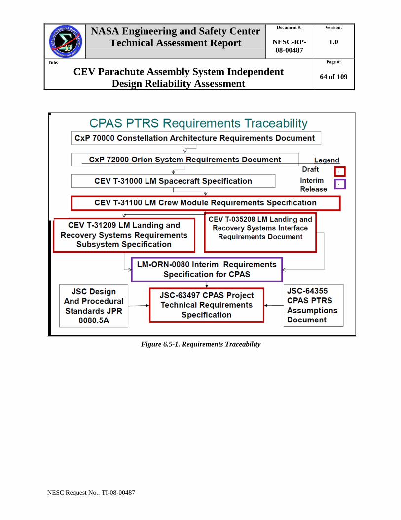
NASA Engineering and Safety Center
Technical Assessment Report
Document #:
NESC-RP-
08-00487
Version:
1.0
Title:
CEV Parachute Assembly System Independent
Design Reliability Assessment
Page #:
64 of 109
NESC Request No.: TI-08-00487
Figure 6.5-1. Requirements Traceability
NASA Engineering and Safety Center
Technical Assessment Report
Document #:
NESC-RP-
08-00487
Version:
1.0
Title:
CEV Parachute Assembly System Independent
Design Reliability Assessment
Page #:
65 of 109
NESC Request No.: TI-08-00487
The first draft of the development test matrix was provided to the assessment team during RP-2.
The draft V&V document was also provided. After returning from its planned assessment hiatus,
the assessment team focused much of its time during RP-2 discussing these items.
6.5.3 Review Period 3—September 2009 through April 2010
At IDR-3, the Project only cursorily reviewed the CPAS baseline design, recognizing that the
ongoing IDAT activity would change the architecture later in the year.
At the review, the Project described the methods by which the draft development test matrix had
been created. Test objectives had been derived principally from risks identified by the Project.
These objectives then were considered in determining ground or flight testing needs. Test
configurations then had been created from parameters required to create test conditions
(e.g., dynamic pressure, altitude, wing loading, wake, whether a representative parachute bay or
FBC was required, etc). Unique test configurations were identified, test objectives were
grouped, and notional test vehicles assigned. The result was fourteen unique flight tests and two
sub-scale series tests. These included main parachute performance evaluations of suspension
line ratios, riser lengths, over-inflation control lines, and canopy porosity. The sub-scale drops
were to evaluate the uncertainties related to CPAS separation from the parachute test vehicle
(PTV).
The assessment team had assessed the test matrix independently and identified much of this
detail prior to the IDR-3 (see Figure 6.5-2). The assessment team presented its second interim
outbrief to the Project the same week in September 2009 as the IDR-3.
When the CPAS architecture changes based on IDAT recommendations were adopted in
November 2009, the assessment team discussed these and created a revised ‗event spreadsheet‘
for this architecture to help the team identify areas of risk and concern that would necessitate test
plan changes.
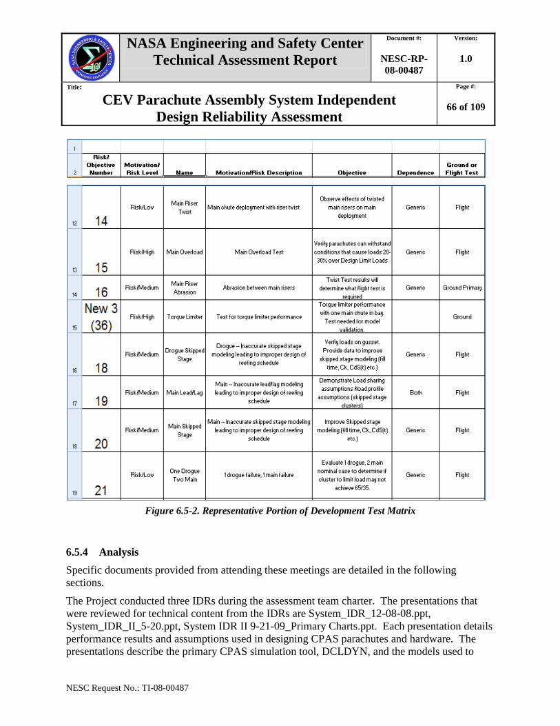
NASA Engineering and Safety Center
Technical Assessment Report
Document #:
NESC-RP-
08-00487
Version:
1.0
Title:
CEV Parachute Assembly System Independent
Design Reliability Assessment
Page #:
66 of 109
NESC Request No.: TI-08-00487
Figure 6.5-2. Representative Portion of Development Test Matrix
6.5.4 Analysis
Specific documents provided from attending these meetings are detailed in the following
sections.
The Project conducted three IDRs during the assessment team charter. The presentations that
were reviewed for technical content from the IDRs are System_IDR_12-08-08.ppt,
System_IDR_II_5-20.ppt, System IDR II 9-21-09_Primary Charts.ppt. Each presentation details
performance results and assumptions used in designing CPAS parachutes and hardware. The
presentations describe the primary CPAS simulation tool, DCLDYN, and the models used to

NASA Engineering and Safety Center
Technical Assessment Report
Document #:
NESC-RP-
08-00487
Version:
1.0
Title:
CEV Parachute Assembly System Independent
Design Reliability Assessment
Page #:
67 of 109
NESC Request No.: TI-08-00487
characterize the performance of the parachute system. An overview of multiple aspects of CPAS
are presented, including the Con Ops, materials, interfaces, environment, proposed chute
difficulties (torque limiter, confluence fitting, bag retention system, etc.), mass properties, safety,
and reliability.
During the IDR-3, a breakout session on simulation models and methods was conducted.
Presentation material was detailed in CPAS_Sim_Methods_2009-09-21,
Osiris_HiFiModel_Overview.ppt, and PA1_CPAS_GNC_TIM.ppt. The session presentations
describe analysis and reconstruction approaches of parachute test data by modeling and
simulation. The session also helped to identify how one of the primary simulations for Orion
(Outdoor Scene and Infrared Image Simulation or OSIrIS) would incorporate its own parachute
model with comparisons to models in Decelerator System Simulation (DSS).
SE&I Integrated Product Team (IPT) teleconferences were attended by various assessment team
members from January 2009 through March 2010. The meetings were reviewed by the
assessment team for CPAS design decisions and methodology. Hardware IPT and CPAS MVP
planning meetings were also attended during the same time frame.
IDAT charts from the period of August 2009 to October 2009 were reviewed for design
decisions and methodology. Specific areas of NESC interest in relation to IDAT are the five
chartered trade spaces:
1. Parachute Architecture—2 Drogue/3 Main, 3 Drogue/3 Main, 2 Drogue/4 Main
2. FBC Removal—Segmented versus Monolothic FBC
3. Forward Bay Volume—Backshell angle modification, FBC modification, structural
design changes
4. LAS/CM Forward Attach—CM/LAS R&R design mitigation, LAS/CM attachment
blisters/wells
5. LAS Architecture—Orientation for post-abort LAS jettison, thrusters/jettison motor/tip
chute jettison assist, straight-to-mains
Drop test reports from the CPAS Development Test Gen-1 Series for the pilots, drogues, and
mains (ESCG-4390-080-SP-DOC-0029, ESCG-4390-08-DOC-0028, and ESC-4390-08-SP-
DOC-0036) were reviewed for simulation model accuracy and prediction of parachute
performance.
The Apollo Program Experience Report (NASA-TN-D7437) and the Apollo 15 Parachute
Failure Report (NASA-TM-X-67439) were reviewed for applicable lessons learned.
Various PowerPoint®, Word
®, and Excel
®, documents provided from CPAS were reviewed that
include the CPAS organizational charts, MVP, PTRS, assumptions document, interface
documents, test plans, and reliability PRA.
Various papers were reviewed detailing the Orion Guidance, Navigation, and Control (GN&C)
architecture utilized by CEV to guide the entry vehicle to the parachute deploy conditions and
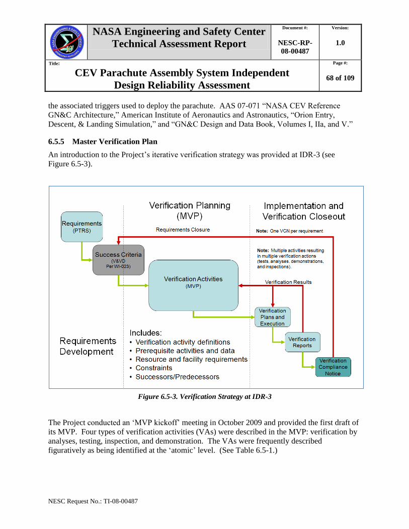
NASA Engineering and Safety Center
Technical Assessment Report
Document #:
NESC-RP-
08-00487
Version:
1.0
Title:
CEV Parachute Assembly System Independent
Design Reliability Assessment
Page #:
68 of 109
NESC Request No.: TI-08-00487
the associated triggers used to deploy the parachute. AAS 07-071 ―NASA CEV Reference
GN&C Architecture,‖ American Institute of Aeronautics and Astronautics, ―Orion Entry,
Descent, & Landing Simulation,‖ and ―GN&C Design and Data Book, Volumes I, IIa, and V.‖
6.5.5 Master Verification Plan
An introduction to the Project‘s iterative verification strategy was provided at IDR-3 (see
Figure 6.5-3).
Figure 6.5-3. Verification Strategy at IDR-3
The Project conducted an ‗MVP kickoff‘ meeting in October 2009 and provided the first draft of
its MVP. Four types of verification activities (VAs) were described in the MVP: verification by
analyses, testing, inspection, and demonstration. The VAs were frequently described
figuratively as being identified at the ‗atomic‘ level. (See Table 6.5-1.)

NASA Engineering and Safety Center
Technical Assessment Report
Document #:
NESC-RP-
08-00487
Version:
1.0
Title:
CEV Parachute Assembly System Independent
Design Reliability Assessment
Page #:
69 of 109
NESC Request No.: TI-08-00487
Table 6.5-1. MVP Verification Strategy
Verification by Analysis
High-fidelity dynamic/structural simulation process for Monte Carlo analysis to provide static and dynamic loads
including protuberance interaction and friction and vehicle dynamics response to parachute and harnessing effects.
Likely analogous to landing loads analysis process.
Development team to develop, verify, validate, and accredit simulation.
Analysis team to derive, analyze, and verify structural margins at all points.
Requires Simulation tool for dynamics of adverse attitude riser contact.
Requires Additional finite element model analyses (stress and loads/dynamics).
Verification by Test
Series of tests to validate/anchor simulation models (parachute effects, aero effects).
Spin tunnel testing (new, cheap—around $50K)
¼-scale drop testing (new, in CPAS impact estimates for 3d/3m)
Full-scale pallet testing (new, in CPAS impact estimates for 3d/3m)
Pad Abort (PA)-1 flight test
CPAS PTV drop testing
Ascent Abort-2 flight test
PA-2 flight test
Static ground testing using structural test authority for off-nominal loads applications including cases when wrapped
around heatshield with opportunity to limit these as flight simulations are matured.
Verification by Inspection
Inspection (and perhaps some demonstration) for riser/structure interaction late in assembly sequence to verify the
assessment team captured all possible interference.
Verification by Demonstration
Utilize current CPAS drop testing for system certification.
Development PTV tests:
1 with drogue failure (To Be Decided (TBD) attitude/rate behavior)
Qual PTV tests:
1 off-nominal attitude (e.g., apex forward)
1 with drogue failure (TBD attitude/rate behavior)
At the MVP kickoff, the Project discussed plans to conduct follow-on activities to consolidate
and aggregate VAs and to extend the tasks to accommodate hazard-control requirements,
interface controls and other requirements, and qualification risks. They stated an intent to
comprehensively capture VAs during the engineering development phase.
After the MVP kickoff and during subsequent Project meetings, the assessment team uncovered
insufficient Project understanding of the test and verification recommendations the assessment
team had provided in September 2009. To remedy this, the assessment team conducted a
question-and-answer meeting in December 2009. This document is included in Appendix C.
NASA Engineering and Safety Center
Technical Assessment Report
Document #:
NESC-RP-
08-00487
Version:
1.0
Title:
CEV Parachute Assembly System Independent
Design Reliability Assessment
Page #:
70 of 109
NESC Request No.: TI-08-00487
6.6 Organizational Complexity
The assessment team examined the organizational framework in which the Project was operating
and discussed risks it could pose to the design and development of a reliable system. (See
Figures 6.6-1, 6.6-2, 6.6-3, and 6.6-4.)
It is pertinent to describe the partition of responsibility for development of Orion hardware here.
The CM included the gussets, tunnel, bulkhead, FBC, avionics, riser cutters, and LRS. The LRS
was comprised of two principal components: the Aerodynamic Decelerator System (ADS) and
the CMUS. The ADS was comprised principally of CPAS, plus other subcomponents including
mortars, riser cutters, and auxiliary parachute guns (if any). (See Figure 6.6-5.)
AS was contracted through Jacobs ESCG to provide design and development data, test hardware,
and test data for the Project. AS did not have a production contract for CPAS at the time of this
review.
The Project was responsible for parachutes and their components, risers, deployment bags,
confluence fittings (if any), torque reducer (if any), and other ancillary components.
The Orion Project‘s lead contractor, LM, was responsible for several other components critical to
CPAS reliability, including all mortars, all riser cutters, the fairlead fitting, and auxiliary
parachute guns (if any). LM was also responsible for integrating CPAS into the larger LRS,
which included the CMUS. LM also was responsible for integrating the LRS into the CM and
for CM features critical for CPAS reliability, including the FBC and its jettison system, and the
forward bay gussets and tunnel.
The assessment team‘s understanding was that the design development data and test data were to
be provided by AS (through its contract with Jacobs ESCG) to the Project. The parachute
system ultimately would be provided to LM as GFE.
The CPAS SE&I (see Figure 6.6-1) and S&MA (see Figure 6.6-2) functions were shared by
NASA and Jacobs ESCG, but top-level integration authority resided with the LM Engineering
Review Board (see Figure 6.6-4).

NASA Engineering and Safety Center
Technical Assessment Report
Document #:
NESC-RP-
08-00487
Version:
1.0
Title:
CEV Parachute Assembly System Independent
Design Reliability Assessment
Page #:
71 of 109
NESC Request No.: TI-08-00487
Figure 6.6-1. CPAS Organization, SE&I

NASA Engineering and Safety Center
Technical Assessment Report
Document #:
NESC-RP-
08-00487
Version:
1.0
Title:
CEV Parachute Assembly System Independent
Design Reliability Assessment
Page #:
72 of 109
NESC Request No.: TI-08-00487
Figure 6.6-2. CPAS Organization, S&MA

NASA Engineering and Safety Center
Technical Assessment Report
Document #:
NESC-RP-
08-00487
Version:
1.0
Title:
CEV Parachute Assembly System Independent
Design Reliability Assessment
Page #:
73 of 109
NESC Request No.: TI-08-00487
Figure 6.6-3. CPAS Project Functional Team Organization Chart
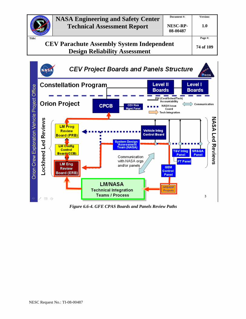
NASA Engineering and Safety Center
Technical Assessment Report
Document #:
NESC-RP-
08-00487
Version:
1.0
Title:
CEV Parachute Assembly System Independent
Design Reliability Assessment
Page #:
74 of 109
NESC Request No.: TI-08-00487
Figure 6.6-4. GFE CPAS Boards and Panels Review Paths

NASA Engineering and Safety Center
Technical Assessment Report
Document #:
NESC-RP-
08-00487
Version:
1.0
Title:
CEV Parachute Assembly System Independent
Design Reliability Assessment
Page #:
75 of 109
NESC Request No.: TI-08-00487
Figure 6.6-5. CPAS/ADS/LRS/CM Interface Definitions at Conclusion of RP-3
7.0 Data Analysis
This section summarizes the assessment team‘s analyses of relevant Project information
described in Section 6.0. Section 7.1 provides an analytical context for the three sets of findings,
observations, and interim NESC recommendations that are reproduced in Appendices B, C,
and D. Section 7.2 provides team analyses supporting the findings, observations, and final
NESC recommendations provided in Section 8.0.
7.1 Interim Analytical Assessment of Project Information
The three NESC stakeholder summaries provided to the Project in April 2009, September 2009,
and April 2010 provided time-sensitive interim recommendations intended to lower project
technical and schedule risks. The CPAS architecture changed considerably during this time, and
the assessment team‘s interim deliverables reflected those changes as they occurred. Many
LRS
CM
ADS
CPAS
Mains
Retention
System
Riser Torque
Decoupler
Fitting
Main Parachute
Deployment Bag
Reefing cutter
Reefing line, 2nd stage
Reefing line, 1st
stage
Reefing cutter
Main Chute/Riser
Fabric Link
Main Riser
Ringsail Canopy
Physical
PYRO
(cutters)
ECLSS
GNC
PTC
Prop
Contamination
Force
Stroke
Functional
CPAS MP
Roll Torque
Deploy Conditions
Contamination
Thermal
Load
Thermal, KOZ, Edges
GSE
No IF with GSE
NO CPAS IF:
AV
CHHA
ECSES
EPS
EMI/EMC/Bonding
Induced Environment
per EDD
Natural environment
per DSNE
WIRING Connectors
Harnesses
Secondary Struc Attach
EPS AV
CMUS
Temperature
sensorsHeaters
Physical,
KOZ
Edges
Surface Finish
TPS
STR
MECH LIDS
FBCR
DMJS
Thermal
KOZ
Edges
Surface Finish
Attach point load
Mass
Volume
Tie-downs
Thermal
KOZ
Edges
Surface Finish
Thermal
KOZ
Edges
Surface Finish
Purge, Vent
and Drain
Humidity
Temperature
Chemical Composition
Physical
Functional
Pilot
Mortars
Drogue
Mortars
Initiation
Volume
Mass
Edges
Surface
Velocity
Timing
Thermal
Volume
Mass
Edges
Surface
Velocity
Impulse load
Timing
Thermal
Thermal
KOZ
Edges
Surface Finish
Push-off force
Thermal
KOZ
Edges
Surface FinishDrogue
Riser
Cutters
Main
Riser
Cutters
Uprighting Bag
Assembly
Inflation Gas
Assembly
Gas Flow
Assembly
Parachute Riser to
Buoyancy Restrain Straps
CloseoutGusset closeout
Bulkhead closeout
Tunnel closeout
Fwd MDC ramp
Aft MDC ramp
Wiring closeout
Thermal
Mechanical
Thermal
Mechanical
Pilot Parachute
Deployment Bag
Pilot Chute/Riser
CM Mass Properties
data to CPAS
CM Aero data to
CPAS
Drogue Parachute
Deployment Bag
Reefing Line, 2nd
stage
Reefing Line, 1st
stage
Drogue Chute/Riser/Harness
Reefing cutter x2
Reefing cutter x2

NASA Engineering and Safety Center
Technical Assessment Report
Document #:
NESC-RP-
08-00487
Version:
1.0
Title:
CEV Parachute Assembly System Independent
Design Reliability Assessment
Page #:
76 of 109
NESC Request No.: TI-08-00487
related to developmentally transient architectural features that do not apply at the time of writing
of this final report.
7.1.1 Review Period 1—December 2008 through March 2009
The evolution of the CPAS architecture during RP-1 is described in Section 6.3.1. The other
items reviewed during RP-1 are described in Sections 6.4.1 and 6.5.1. At the time of IDR-1 in
December 2008, the CPAS PDR was anticipated in June 2009.
Beginning with the IDR-1, the assessment team reviewed a large amount of design data and
project work products during RP-1, covering a broad range of issues:
Architecture
Design features
Design development methodology
System function
Reliability methodology
Requirements
Analysis and modeling
Organizational aspects that affect reliability
The assessment team also discussed various architectural options under consideration by the
Project. The request for the assessment team had explicitly assumed there was an ―existing‖
design, but a concrete baseline did not exist and the Project‘s reliability work products were
commensurately immature and their development test plans were still under development and not
available for the assessment team to review.
To compile and organize the many relevant issues discussed by the assessment team, a
preliminary list of 336 factual statements (FSs) and 96 experience-based observations (EOs) was
created.
The assessment team derived from this list 20 findings, 24 observations, and 30 interim NESC
recommendations. These were approved by the NRB and outbriefed to Project stakeholders at
AS in Santa Ana, CA, in April 2009.
The first stakeholder outbrief and the supporting list of FSs and EOs can be found in
Appendix B.
The interim NESC recommendation R-3 from the first stakeholder outbrief is discussed further
in Section 7.2.1.1, as part of narrative that supports the final NESC recommendation R-1 in this
report.
NASA Engineering and Safety Center
Technical Assessment Report
Document #:
NESC-RP-
08-00487
Version:
1.0
Title:
CEV Parachute Assembly System Independent
Design Reliability Assessment
Page #:
77 of 109
NESC Request No.: TI-08-00487
7.1.2 Review Period 2—April 2009 through August 2009
The evolution of the CPAS architecture during RP-2 is described in Section 6.3.2. The other
items reviewed during RP-2 are described in Sections 6.4.2 and 6.5.2. During RP-2 the CPAS
architecture continued to evolve. At the time of IDR-2 in May 2009, the CPAS PDR was
anticipated in November 2009.
After discussing issues learned at the IDR-2, the assessment team took a 2-month hiatus,
discontinued monitoring CPAS meetings and discontinued conducting weekly team meetings,
until July 2009. This stand-down was to allow the Project to make progress toward a more
concrete design architecture definition, corresponding reliability work products, and a draft
development test plan. The assessment lead attended the Orion Subsystem Design Review in
June 2009 and the System Module Review in July 2009, to remain abreast of CPAS design
developments.
The assessment team began meeting again in July 2009 when a draft development test matrix
and a draft verification plan were made available by the Project for review. While keeping
abreast of design architecture options being vetted by the IDAT, the assessment team focused
most of its discussions on the Project‘s development test plans, analyses plans, and verification
activities. The assessment team discussed test matrices derived from functional decomposition
of systems and created a sample Functional Verification Matrix. The assessment team also
discussed applications of experimental design in planning CPAS development and verification
activity.
The assessment team created a second outbrief of three findings, two observations, and two
interim NESC recommendations. These were approved by the NRB and outbriefed to Project
stakeholders at JSC in September 2009.
One of the two recommendations provided specific guidance on the application of DOE
techniques that can improve the effectiveness and resource-efficiency of the Project‘s
development testing effort. The other recommendation outlined a process for creating a
comprehensive matrix of candidate verification tasks that the Project could use as a check against
their nascent verification plan, to identify potential gaps and/or redundancies.
The assessment team included supplemental material in the stakeholder outbrief, including an
introductory explanation of potential benefits of using methods of statistical DOE, in particular
comparison to using ‗one factor at a time‘ testing methods, and the sample Functional
Verification Matrix. During RP-3 the assessment team created a list of frequently asked
questions (FAQs) pertaining to DOE (described in the following section).
The second stakeholder outbrief, the sample of a Functional Verification Matrix, the DOE
tutorial, and the list of FAQs can be found in Appendix C.
NASA Engineering and Safety Center
Technical Assessment Report
Document #:
NESC-RP-
08-00487
Version:
1.0
Title:
CEV Parachute Assembly System Independent
Design Reliability Assessment
Page #:
78 of 109
NESC Request No.: TI-08-00487
The interim NESC recommendation R-31 from the stakeholder interim outbrief 2 is discussed
further in Section 7.2.3.2 as part of narrative that supports the final NESC recommendation R-6
in this report.
7.1.3 Review Period 3—September 2009 through April 2010.
The evolution of the CPAS architecture during RP-3 is described in Section 6.3.3. The other
items reviewed during RP-3 are described in Sections 6.4.3 and 6.5.3. At the time of IDR-3 in
September 2009, the CPAS PDR was anticipated in March 2010. By the end of RP-3, the PDR
was scheduled for August 2010.
At the beginning of RP-3, the assessment team composition was adjusted. The assessment
team‘s structures discipline expert and one parachute design development expert left the team. A
second DOE expert and a heritage systems safety expert were added to the team.
The assessment team continued to discuss various design options being vetted by the IDAT.
The assessment team also continued to discuss the Project‘s draft verification plan. The
assessment team detected that Project personnel may not have fully understood the interim
NESC recommendations that were communicated in September 2009, so the team compiled a list
of clarifying answers to questions that were being asked by CPAS personnel. This document of
FAQs was not an NRB-approved product. The assessment team conducted a meeting with the
Project in December 2009 to discuss these questions.
After the Project adopted IDAT recommended architecture, the assessment team assessed the
impact to design reliability.
The assessment team created a third outbrief of 33 findings, 20 observations, and 23 interim
NESC recommendations. These were approved by the NRB and outbriefed to Project
stakeholders at JSC in April 2010.
The assessment team put backup material in the outbrief including an example of reliability
growth trending analysis and an example of the potential problems with one-factor-at-a-time
testing.
The stakeholder outbrief 3 and the two noted example items can be found in Appendix D.
7.2 Final Analytical Assessment of CPAS Project Information
This section provides a narrative summary of the team‘s assessment of Project information
current at the end of the overall assessment period, in April 2010.
Throughout the entire period of assessment review, the CPAS architecture was evolving. During
the third review period, a final architecture was selected based on recommendations from an
IDAT chartered to resolve key CPAS integration issues. Several outstanding interim NESC
recommendations were addressed by this new architecture.

NASA Engineering and Safety Center
Technical Assessment Report
Document #:
NESC-RP-
08-00487
Version:
1.0
Title:
CEV Parachute Assembly System Independent
Design Reliability Assessment
Page #:
79 of 109
NESC Request No.: TI-08-00487
Included in this section are team assessments resulting in findings that support the final NESC
recommendations in Section 8.0. These recommendations were approved by the NRB prior to
completion of the report and provided to Project stakeholders prior to the CPAS PDR in
August 2010.
7.2.1 Architecture
7.2.1.1 Pack Volume Risks
The volumetric requirements for any parachute system are driven by vehicle recovery weight,
maximum deployment dynamic pressure, allowable packing density, materials used, and
terminal descent velocity. Higher vehicle weight or higher dynamic pressure would demand
stronger and possibly larger parachutes, which in turn would demand more volume. Once a
parachute compartment volume has been allocated, it can be difficult to change the design to
provide more volume in response to future demands.
The CPAS Subsystem's PTRS specified that the CM was required to provide volume to ensure
CPAS main parachute density was ≤ 38 lbm/ft³. For the first two review periods, the projected
main parachute pack density was between 43.7 and 54.2 lbm/ft³.
There was consensus on the assessment team and across the wider parachute community that as
parachute pack density increases, reliability risks also increase. Risks include damage to
hardware items and soft materials. Damage to some parachute components can lead to parachute
inflation malfunctions that cause loads to exceed design limit loads. Damage to components can
also cause them to fail at loads below design limit loads. Either of these outcomes can result in
catastrophic parachute system failures.
Some parachute systems on emergency escape systems or unmanned weapons systems have
successfully incorporated high-density parachute packs but these were not primary landing
systems used on manned vehicles.
During the Apollo Program ELS Block II development program, parachute performance
requirements increased but the volume allocated to the main parachutes remained constant,
resulting in increased packed density. On the Apollo Program, increased rates of parachute
component damage were observed in proportion to increases in pack density. Innovative
packing solutions with rigorous certification efforts and personnel training requirements were
needed to mitigate these risks. Functional verification could not be performed on these high-
density parachute systems during much of their manufacture, so rigorous, time-consuming, and
costly manufacturing and installation practices were implemented.
The Project should create and maintain a budgeting process for volume and pack density. The
volume assigned to CPAS in the CM forward bay should be cataloged as to gross dimensions,
volume, shape, and draft. This should include the space for all CPAS components, including but
not limited to the main parachutes, drogues, pilot chutes, risers, bridles and associated hardware,
NASA Engineering and Safety Center
Technical Assessment Report
Document #:
NESC-RP-
08-00487
Version:
1.0
Title:
CEV Parachute Assembly System Independent
Design Reliability Assessment
Page #:
80 of 109
NESC Request No.: TI-08-00487
and any other systems stored in this volume. A volume margin should be added and each design
change proposed during development should be evaluated for impact to this budget. The
assessment team observed that virtually every escape or recovery parachute system experienced
increases in weight requirements during development, including the Apollo Program ELS. This
history suggests that Orion CM weights will likely increase once the vehicle enters operation,
making it necessary to continue to monitor the vehicle parachute compartment volumetric
margins.
The volume provided by the new CM OML described in Section 6.3.3 allowed the CPAS main
pack shape to be simplified and the pack density to be reduced to below the required level.
However, the assessment team assessed that the continued risk of future volume demands was
improperly prioritized by the Project.
F-1. The CPAS Project has not implemented a formal process to manage volume growth of
components in the CM forward bay during design, development, evaluation, and
operation.
7.2.1.2 Roll Control Risks
To reduce water-landing loads on the CM structure and its crew, the CM was to be oriented to a
toe-forward orientation just prior to water landing. To facilitate this, CPAS included a metallic
torque reducer keeper that would deploy with the main parachutes and gather the main risers to a
point above their single point attachment location on the CM. This would allow a section of
gathered risers to ‗twist up‘ and ‗untwist‘ with less than 450 ftlbf when the CM was suspended
under its opened main parachutes. With the roll torque limited as such, the CM RCS would have
sufficient authority to roll the CM to an optimum water entry angle prior to landing.
The assessment team assessed that deployment of a keeper on the CPAS main risers had no
apparent design precedent and posed risks to CPAS reliability. Extensive testing would be
necessary to quantify these risks and demonstrate reliable function of this DFMR component.
The assessment team thought that using the RCS while suspended on parachutes could also pose
a risk of causing burning or oxidizing damage to parachute textile materials, especially at high
CM angular rates and attitudes. This was the suspected cause of one main parachute failure
during descent of the Apollo 15 CM.
In the course of discussing the inclusion of the keeper, the assessment team assessed other risks
that may arise when using this method to achieve CM orientation relative to ground track
heading. To impact a wave slope in the necessary manner would require knowing and managing
a number of variables in a short period of time near the water. These variables would include the
descent rate of the CM, the number of degrees of roll reorientation required, the target roll rate,
the swing angle under the parachutes, the drift rate and direction, and the tolerance in the
NASA Engineering and Safety Center
Technical Assessment Report
Document #:
NESC-RP-
08-00487
Version:
1.0
Title:
CEV Parachute Assembly System Independent
Design Reliability Assessment
Page #:
81 of 109
NESC Request No.: TI-08-00487
heading. Other possible variables associated with proximity to the water surface could include
wind shears and gusts.
A successful reorientation maneuver may also require a sophisticated sensing system to
determine water surfaces conditions at touchdown for computation of the CM‘s terminal
orientation requirement. The assessment team knew of no precedent for this type of system. It
was not within the assessment team‘s scope of review to investigate onboard sensor system
requirements.
The assessment team concluded that the Orion Project should consider chartering an IDAT,
perhaps delegated to the previous IDAT‘s successor, the Earth Landing System Functional
Integration Team (ELS-FIT), to conduct a comprehensive assessment of the overall feasibility
and ramifications of using the CM RCS to perform the function of reorientation of the CM prior
to water landing.
The IDAT should include representatives from the CM subsystems that interface with or are
dependent on the RCS function, including CPAS. The assessment should address the risks of
inclusion of a deployable metallic keeper in CPAS and should also include an assessment of LRS
verification plans.
The IDAT assessment scope could include:
The overall feasibility and ramifications of using the RCS for touchdown roll control
Assessment of the risks (likelihood/consequence) versus benefits to CPAS and other
subsystems
The impact of prohibiting the use of the RCS once the FBC panels are deployed
The impact of a requirement to not dump RCS fuel in any direction where heat, fuel, or
oxidizer can reach any part of the parachute system
Inclusion of a deployable metallic torque limiter in CPAS
Design of the CM structure for water impact at worst-case combinations of water-surface
conditions and vehicle-landing attitudes
The risks of landing with fuel in the RCS tanks
The effects of parachute oscillation
The ability to sense CM drift direction
The ability to sense water-surface conditions beneath the CM prior to landing
The methods to determine which heading to take to impact a dynamically changing wave
slope just right
RCS command sequencing
The extent and complexity of an adequate development and certification plan for the RCS
NASA Engineering and Safety Center
Technical Assessment Report
Document #:
NESC-RP-
08-00487
Version:
1.0
Title:
CEV Parachute Assembly System Independent
Design Reliability Assessment
Page #:
82 of 109
NESC Request No.: TI-08-00487
F-2. Deployment of a torque reducer keeper on the CPAS main risers has no design
precedent and poses risks to CPAS reliability. Extensive testing will be necessary to
quantify these risks and demonstrate reliable functionality.
F-3. Using the CM RCS to orient the CM into a toe-forward position just prior to water
landing is unprecedented and is an integrated issue that introduces risks to CPAS and
the CM structure.
7.2.2 PRA and Other Reliability Products
7.2.2.1 PRA Estimation Methods
At the first IDR in December 2008, a draft of the RAESR was presented that included a HA,
FMEA, and FTA. The RAESR provided a functional description of the system and
decomposition based on the current architecture, which was immature at this time. In addition, a
PRA was presented that estimated catastrophic main parachute failure leading to LOC at 1 in 217
without a statement of uncertainty.
The PRA estimate was dominated by a failure mode seen in the SSP SRB historical development
data that involved re-contact during parachute deployment. During design evolution, the FTA
and FMEA were updated in accordance with design changes. The FMEA was used to track
single point failures, which were briefed to the Project design team. However, the NESC
assessment team noted that reliability analyses were severely limited by a lack of appropriate test
data to estimate the FTA probabilities. In the following paragraphs, significant events in the
reliability and PRA‘s evolution are highlighted.
The assessment team had determined that the IDR-1 LOC estimate was invalid because the SSP
SRB failure mode was not applicable to the CPAS architecture. Consequently, the CPAS LOC
estimate was considered not accurate and with great uncertainty. The PRA also had gaps caused
by a lack of valid test data on which failure estimates could be based.
As the CPAS architecture evolved toward a system similar to the Apollo Program ELS during
RP-3, additional data were sought from historical files from the ELS development program to
use in the PRA. At the end of the team‘s assessment, a significant amount of Apollo ELS data
had been discovered but had not yet been integrated into the PRA.
An EE activity was performed to fill the test data gaps and replace rough order of magnitude EJ
estimates. The EE was based on the architecture current at the time of the exercise. It was
intended to derive a relative ranking of potential failure modes from a small group of parachute
system experts.
The results of the EE were used in subsequent PRA LOC estimates. Details of the EE are
provided in Reference 9.

NASA Engineering and Safety Center
Technical Assessment Report
Document #:
NESC-RP-
08-00487
Version:
1.0
Title:
CEV Parachute Assembly System Independent
Design Reliability Assessment
Page #:
83 of 109
NESC Request No.: TI-08-00487
Because of the existing FTA‘s complexity and the rapidly changing design, a simplified FTA
was developed at the request of the CPAS SE&I lead that was more ―interpretable‖ by design
engineers to support design and development decisions. This second FT attempted to capture
higher-level functional failures rather than individual failure modes. While this FT was more
understandable by the Project design team, the original, more complex FT simultaneously was
maintained during the assessment period and was used for ―official‖ PRA estimates.
The Project provided results from the EE at IDR-3, but those data had not yet been incorporated
into the PRA basic event estimates. Five experts had participated. Based on their answers a top
system-level reliability was estimated to be 1:1,087. Failure to deploy a main parachute (PRA
input value #10) was estimated to be 1:231. A large variance was reported in the component
reliability values. The Project reported that the experts would be asked to reexamine the
resulting estimates as a sanity check. The Project reported that inputs for PRA failure mode
values were to be used to determine top system-level reliability.
The failure probability estimate data derived from the 2009 EE exercise exhibited large variance
that greatly limited its applicability for generating CPAS PRA input values. The large variance
was due mainly to the disagreement between the five experts involved in the study.
The failure probability estimate data derived from the 2009 expert elicitation exercise are invalid
for the Gen-2 architecture. The Project is attempting to modify the EE results to account for
changes in the Gen-2 architecture by removing a number of failure modes that are no longer part
of this architecture. The assessment team agreed that modification of the results in this manner
would not lead to valid probability estimates for the Gen-2 architecture.
The assessment team observed that the PRA appeared to be used principally for computing top-
level LOC estimates to communicate the Orion Project, but it also had influence on the
development test plan, consistent with the Orion Project‘s risk-based approach. This approach
would use the PRA to define and prioritize risks and to define the resources required for testing.
The assessment team considered this approach insufficiently comprehensive for a development
effort. For the Project‘s PRA/risk-based approach to succeed, all primary risks would have had
to have been identified.
As the FMEA evolved, critical failure modes and total failure modes were significantly reduced
(see Table 7.2-1).

NASA Engineering and Safety Center
Technical Assessment Report
Document #:
NESC-RP-
08-00487
Version:
1.0
Title:
CEV Parachute Assembly System Independent
Design Reliability Assessment
Page #:
84 of 109
NESC Request No.: TI-08-00487
Table 7.2-1. Evolution of FMEA from RP-1 to RP-3
FMEA December 2008:
Criticality Amount
1 145
IR 17
1R2 739
1R3 110
1R4 8
Total: 1019
FMEA September 2009:
Criticality Amount
1 2
1R 0
1R2 66
1R3 0
1R4 6
Total: 74
The reliability analyses, including the RAESR and PRA, were reviewed throughout the overall
assessment period. The assessment team found the traceability and veracity of the data
consistently problematic, particularly in the input data to the PRA. Estimated risks contained
historical data, new test data, simulation, and EE results. These sources were neither explicitly
noted in the analyses nor communicated to the Orion Program. The assessment team found
inappropriate statistical distribution assumptions in both experimental and simulation data that
rendered them either under- or over-conservative. The assessment team also found early risk
estimates with no statements of uncertainty, which did not support risk-informed decision-
making.
The original PRA LOC estimates were found to be unsubstantiated due to the use of inapplicable
SSP SRB data based on re-contact during deployment due to the dissimilarity between the CPAS
and SRB architecture.
The assessment team‘s analysis indicated that the lack of applicable test data presented a
formidable challenge to obtaining adequate PRA estimates.
NASA Engineering and Safety Center
Technical Assessment Report
Document #:
NESC-RP-
08-00487
Version:
1.0
Title:
CEV Parachute Assembly System Independent
Design Reliability Assessment
Page #:
85 of 109
NESC Request No.: TI-08-00487
Consequently, the assessment team found that Apollo Program ELS data should be used for PRA
inputs whenever appropriate (by similarity) and when available. During the assessment, a cache
of Apollo Program reports were discovered in a storage facility managed by NG. These data will
be more directly applicable to the current CPAS architecture and should improve PRA estimates.
The assessment team reviewed the design and analysis of the EE exercise and found that the
results were highly variable among the experts. The methods employed appeared to assume that
the elicited events were independent, whereas some were dependent. The assessment team
found that the experts were asked to compare events at disparate levels. The large variability
between the experts suggested lack of agreement and indicated problems with the elicitation
protocol, including the events collection, their precise definition, and/or the analysis approach.
The EE was based on an obsolete architecture. The team assessed that deleting PRA failure
events to attempt to model the current architecture would render the EE ranking invalid. If
another EE were to be conducted, a structured methodology such as an Analytical Hierarchy
Process or a similar decision-ranking technique should be employed. If another EE were to be
conducted, the Project would benefit by seeking an EE discipline expert‘s assistance.
F-4. Failure probability estimate data derived from the 2009 EE exercise exhibited a large
variance, greatly limiting its usefulness for generating CPAS PRA input values.
F-5. Failure probability estimate data derived from the 2009 EE exercise are invalid for the
Gen-2 architecture.
O-1. A large cache of Apollo Program ELS test and reliability reports has been located and
is being retrieved by the Project. Some of these data will be applicable for generating
CPAS PRA input values because the ELS and the CPAS Gen-2 architectures are
functionally similar.
O-2. Top-level system failure probability estimates often are estimated or predicted prior to
PDR, but tests and analyses ultimately must be performed to validate and reduce PRA
input value uncertainties.
7.2.2.2 Use of PRA Estimates for Design Decisions
The impetus for initiating this NESC assessment was an unacceptably high LOC probabilistic
risk estimate reported to the Orion Project. This estimate, based erroneously on inapplicable SSP
SRB data, was conveyed to CxP and CEV Project decision makers without a statement of
uncertainty. If the uncertainty regarding the data‘s inapplicability and lack of statistical
confidence in the LOC point estimate had been communicated, more actionable information
would have been provided to these decision-makers. Proper communication of uncertainty,
particularly for mission-critical parameters such as LOC, is imperative.
NASA Engineering and Safety Center
Technical Assessment Report
Document #:
NESC-RP-
08-00487
Version:
1.0
Title:
CEV Parachute Assembly System Independent
Design Reliability Assessment
Page #:
86 of 109
NESC Request No.: TI-08-00487
The methods used by the Project to generate the PRA input value failure probability estimates
evolved considerably throughout the assessment. Supporting data sources can include heritage
test data or operational data, original test data, EJ, and EE.
PRA is best utilized for optimizing the system‘s reliability. Instead of simply generating a LOC
number, PRA can provide a beneficial tool for improving system reliability. PRA tasks are best
completed with the intention and motivation for improving a system‘s reliability.
The assessment team concluded that the Project should convey to top-level design decision
makers that there presently are large uncertainties associated with the PRA estimates, caused by
a complex and unique parachute design coupled with minimal field test data. For PRA
estimates, data sources (e.g., historical records, CPAS test, analysis, expert opinion), accuracy
limitations, and relevance to the CPAS design must be communicated.
O-3. The Project has used PRA input value failure probability estimates principally to
compute the CPAS contribution to Orion LOC. They have been used secondarily to
help derive development test plans.
F-6. CxP and CEV Project decision makers who have made risk-informed design decisions
based on CPAS LOC estimates were not fully informed of the source of the underlying
data used to generate them. Top-level LOC uncertainties were communicated, but
their method of derivation was not shown.
7.2.3 Requirements, Testing, Analyses, and Verification Planning
7.2.3.1 Requirements
The first draft version of the CPAS PTRS, dated November 2008, was provided at IDR-1 in
December 2008 [Ref. 7]. AS had received it only 2 months previously. During the NESC
assessment period the PTRS was revised once in May 2009. A more substantial revision was
still in progress at the end of the assessment in April 2010. The Project indicated that interim
NESC recommendations targeted to specific requirements would be incorporated into this
version prior to PDR.
At a top level, the assessment team determined that the PTRS (Rev. A) [Ref. 7] did not define
pass/fail criteria quantitatively. Moreover, it did not require an explicit statement of test
suitability, assumptions, and/or statistical confidence in the test and/or simulation data and
analysis. Thus, the PTRS was ambiguous and did not support defining verification test
resources.
In colloquial terms, the PTRS did not state what needs to be known, how well it needs to be
known, or how it will become known that it has been learned for relevant performance metrics
necessary to recommend the system for flight operations.
NASA Engineering and Safety Center
Technical Assessment Report
Document #:
NESC-RP-
08-00487
Version:
1.0
Title:
CEV Parachute Assembly System Independent
Design Reliability Assessment
Page #:
87 of 109
NESC Request No.: TI-08-00487
For example, the format of the descent rate requirement could be stated as, ―The CPAS will
ensure with XX percent statistical power at an effect size of X.X m/s that the CM will not exceed
10.7 m/s.‖ Another example related to component strength might be stated as, ―The CPAS will
ensure with 90-percent confidence that the 0.3-percentile (3 sigma) of the strength of component
X exceeds X ft-lbs.‖
These two examples support rigorously estimating test resources and provide a clear pass/fail
metric to determine when a test objective has been met.
F-7. The PTRS does not define quantitative pass/fail criteria, nor does it require an explicit
statement of test suitability, assumptions, or statistical confidence in the test and/or
simulation data and analysis.
7.2.3.2 Development Test Plan
The assessment team review of the CPAS Gen-1 test reports suggested that in 2007 and 2008
there was no systematic process to establish the basis for and the conduct of testing. The Apollo
Program Experience Report–ELS, NASA TN D-7437, (1973), illustrated the great extent of
testing that was necessary to demonstrate the overall ELS system reliability to verify its
suitability for manned flight. It also illustrated the need for thorough systems integration and
compatibility verification. The ELS Project adopted a comprehensive systems engineering
approach to design, development, and testing to deliver a robust, reliable system.
The assessment team reviewed the draft development test plan during RP-2. It appeared to be a
parachute-centric test plan, a continuation of the Gen-1 testing. The assessment team decided
that it was not a complete plan for demonstrating reliability of an integrated CPAS. The tests in
the matrix did not appear to have been derived with consideration of a functional decomposition
of CPAS parts. The tests showed an incomplete consideration of integrated performance of
CPAS with other LRS components or with other CM subsystems.
The test objectives in the CPAS development test matrix were derived principally from
perceived or assumed system-level risks. Risks in the development test matrix loosely but not
completely reflected risks delineate in the constantly evolving FTAs and PRAs. The assessment
team observed that the risk severities used to rank test objectives were determined by consensus
of the CPAS Project development test team.
A risk-based testing approach has been successfully used during operation of the SSP and air
transport systems to continuously improve system reliability and safety. However, a number of
issues can arise when applying this selective approach during a developmental program that has
little to no recent experience or flight data. It can be difficult to obtain pertinent failure data to
formulate an accurate risk profile and there is a chance of overestimating or underestimating a
given risk. A top-down, risk-based testing approach also can fail to identify developmental

NASA Engineering and Safety Center
Technical Assessment Report
Document #:
NESC-RP-
08-00487
Version:
1.0
Title:
CEV Parachute Assembly System Independent
Design Reliability Assessment
Page #:
88 of 109
NESC Request No.: TI-08-00487
problems associated with process, material, workmanship, design errors, and interfaces. These
can seriously threaten system reliability and can adversely impact development schedules.
Flight, ground, and subscale tests in the matrix were developed from the risk-based objectives.
Flight-test configurations were created from parameters required to create test conditions (e.g.,
dynamic pressure, altitude, wing loading, wake, whether a representative parachute bay or FBC
was required, etc.). Unique test configurations were identified, test objectives were grouped, and
notional test vehicles were assigned. The flight test plan included main parachute performance
evaluations of suspension line ratios, riser lengths, over-inflation control lines, and canopy
porosity. Sub-scale test series were designed to assess risks related to CPAS separation from the
PTV. The matrix included 16 drop tests in various configurations and at various altitudes, and
nine ground tests.
The assessment team‘s view was that the priority of a parachute developmental test program
should be to obtain as much data and learn the strengths and weaknesses of various design
options as quickly as possible without being subject to the rigors and controls associated with
performing qualification or flight certification tests. Concept feasibility tests should be
conducted at the lowest level of sub-components possible. As the architectural elements of a
Project mature and requirements are better defined, more sophistication tests then can be
conducted.
The assessment team concluded that the CPAS development test plan had not been designed
comprehensively and may not have been sufficient to obtain the required knowledge of system
performance to mitigate the design risks. While the plan was derived from perceived or assumed
risks as assessed by the Project, it did not link to all risks and concerns identified by FTA,
FMEA, and PRAs. Some risks were sequestered to an ‗off-scope‘ status. To adequately address
these risks, priority should be given to those system elements identified by the FTA to have the
highest uncertainties, thereby performing ―risk balancing.‖ The scope should include
component-level verification tests to track compliance with requirements and mitigate or accept
risks. Furthermore, the plan should provide V&V of simulation models, which are relied on for
performance estimation in the absence of physical test data.
The assessment team assessed that the development test plan lacked precise objectives and
success metrics that enabled clear decisions regarding when test objectives had been met.
Uncertainty in performance metrics requires replication to assess experimental test variability.
While some system parameters were replicated in the development plan, it exhibited
confounding of multiple factors making it difficult to distinguish individual factor effects. The
development test matrix represented a fraction of all possible combinations, constrained by
practicality, but it did not represent a strategic fraction derived to meet precise objectives.
Given resource limitations and the complexity and highly integrated nature of CPAS, traditional,
one-factor-at-a-time development testing may insufficiently assess performance factors,
environmental factors, and interface interactions. All of these can affect system reliability. The
assessment team concluded that a statistics-based DOE approach should be considered. DOE
NASA Engineering and Safety Center
Technical Assessment Report
Document #:
NESC-RP-
08-00487
Version:
1.0
Title:
CEV Parachute Assembly System Independent
Design Reliability Assessment
Page #:
89 of 109
NESC Request No.: TI-08-00487
could provide an integrated, factorial test design to strategically and comprehensively plan the
CPAS development tests. Such an approach would at a minimum include defining: (1) precise,
quantifiable test objectives; (2) required statistical confidence to support test results, linked to
risks and consequences; and (3) mathematical justification of test methodology and resources to
support objectives and provide required confidence.
The DOE approach would also assist identifying what tests could be conducted for model
validation, sub-system verification, and full-system verification and qualification.
F-8. The CPAS ‘one-factor-at-a-time’ development test program will be less efficient in
assessing performance, environmental factors, and interface interactions that could
affect system reliability than could be possible using statistics-based DOE techniques.
7.2.3.3 Ground Testing
The assessment team determined that the test plan placed an inappropriately low emphasis on
ground testing as an effective means for understanding and assessing top risks early in the
development phase. The assessment team concluded that four ground test programs were
particularly needed at this time to mitigate risks associated with the following key events in the
CPAS Con Ops:
1. Main parachute pack retention and release.
2. FBC panel jettison and trajectory.
3. Pilot parachute interference or contact with a panel during deployment following an
abort.
4. Drogue parachute interference or contact with a panel during deployment following a
nominal reentry.
7.2.3.4 Main Pack Retention System
The team assessed reliability risks with the main parachute pack retention system as it evolved
throughout the assessment. At the end of RP-3 the system relied on a series of daisy-chain loops
to retain the main parachute d-bag to CM gussets and to react flight loads. While this approach
has been used successfully in other systems, including the Apollo Program, the assessment team
thought that for CPAS the proposed method exhibited rigging complexity that introduced new
risks of failed or delayed extraction of a main parachute pack.
As described in Section 6.3.3, the retention system design would incorporate flaps that restrained
the main parachute packs along the side edges and interfaced to the segment gusset walls. The
mechanism by which two pilot riser halves would impart forces to unzip their associated daisy-
chain loops appeared immature. The riser halves would require one-for-one integration with
each locking loop to pull each loop through its associated grommet. There was an implied
NASA Engineering and Safety Center
Technical Assessment Report
Document #:
NESC-RP-
08-00487
Version:
1.0
Title:
CEV Parachute Assembly System Independent
Design Reliability Assessment
Page #:
90 of 109
NESC Request No.: TI-08-00487
assistance from the pilot chute risers to assist in the unzipping of the daisy chain without details.
This concept had no apparent precedent and introduced development risk.
There had been no demonstration of this proposed release method and no previous example
shown. The team assessed that there was substantial risk of abrasion and heat damage to the
daisy-chain assembly, which could result in either failure to release or premature release of a
main pack. Either of these could result in a total main parachute malfunction. The assessment
team concluded that these risks should be retired by a series of demonstrations of the retention
release function prior to in-flight full-system testing. These tests could include the addition of
abraded or thermally damaged daisy-chain loops, to fully evaluate the robustness of the design.
At the end of RP-3, the main parachute d-bag concept contained a system of corsets and beckets
on the outer surface to support the convex-curved upper-outer edge of the main parachute pack.
As the main parachute pack density increased during development, it became more difficult for
the parachute retention system to retain the outer surface shape of the d-bag through the total
mission environmental cycle. The assessment team assessed that it will be imperative for the
retention system to maintain the clearance between the outer surface of the d-bag and the inner
surface of the FBC. Inertial and vibration forces may shift a pack in its retention system, altering
its top and outer surfaces and particularly affecting its curved upper-outer edge. Such movement
or distortion could allow contact of the d-bag with the FBC IML, consequently damaging
parachute components or the airbags that jettison the FBC panels.
The assessment team noted that the CxP Ares 1-X recovery parachute failure investigators
determined that a contributing cause of that failure was premature activation of a first stage
parachute reefing line cutter, possibly from excessive movement in the parachute pack during
flight prior to deployment. Ground tests can help ensure the adequacy of a main cutter actuation
system against design load safety margins, and this can preclude premature reefing line cutter
initiation during packing, transport, or flight, while ensuring actuation during the dynamic
conditions of deployment. Cutter design should include a method to detect a premature firing at
least to the point of installation.
The assessment team concluded that the Project‘s planned ground test was insufficient to address
the identified risks. The Project should conduct ground tests to assess the viability of the main
pack retention system early in the development effort, using a representative parachute
compartment and parachute system. Testing should include ground static, thermal, inertial,
shock, and vibration loads as part to any evaluation. The ability of the retention system to
securely hold the CPAS components in place should be evaluated during these tests, including
but not limited to, preventing gross movement and contact with the FBC IML. The effect on
internal components such as the reefing line cutters should also be evaluated.
F-9. The ground test portion of the Project’s development test matrix insufficiently
addresses risks associated with the main parachute pack retention and release system.
NASA Engineering and Safety Center
Technical Assessment Report
Document #:
NESC-RP-
08-00487
Version:
1.0
Title:
CEV Parachute Assembly System Independent
Design Reliability Assessment
Page #:
91 of 109
NESC Request No.: TI-08-00487
7.2.3.5 Forward Bay Cover
The assessment team assessed that the Project decision to segment the FBC into six airbag-
jettisoned panels was made with limited consideration of key consequential aspects. Among
these were effectiveness of the multiple panel design, fail-safe requirement, airbag load reaction
on the packed main parachutes, panel separation line features, volumetric requirements, and
panel release velocity uncertainties. The assessment team observed that multi-body trajectory
analyses were not conducted of dispersed relative trajectories of the panels, drogue chutes, pilot
chutes, main chutes, or other liberated components.
The team assessed that the change from a monolithic FBC to the six-panel configuration
introduced additional complexity and failure modes. Project analyses of the risks and
consequences of unsuccessful panel jettison due to either MDC or airbag failure were not shown.
A failure of one or more of the panels to jettison may result in the improper deployment; failure
to deploy; or damage to the drogue, pilot, or main parachutes or to associated risers, bridles, or
CMUS components. It was not shown if retained panels were designed to break away by drogue
or pilot parachute deployment as a back-up mode of jettison.
The team assessed that the jettison airbag system that was intended to thrust the individual panels
away from the CM imposed additional complexity and sources of risk. One Project briefing
indicated that each airbag would exert 32 psi over an area of 59 in2 on the face of the main
parachute pack. This would result in a total force of almost 1,900 pounds.
Airbag forces applied against the face of a main parachute pack assembly would represent a
hazard to the deployment bag, its contents, and its retention system, possibly leading to damage
to the main parachute components or premature release by rupturing the securing system.
Airbag forces applied against the face of the drogue mortars could cause failure of the cover
shear pins, leading to premature release of the drogue parachute. The addition of an airbag push-
off structure in the sixth forward bay sector may introduce riser entanglement risks.
The use of individual airbags required interconnection to redundant pressure source for inflation,
and redundant initiation. This multiplied the source of risk of failure. The airbags were shown
to be attached directly to the panels, putting them at risk of thermal damage during reentry. As
of the end of RP-3, no ground tests had been conducted to demonstrate the function or robustness
of the panel jettison design.
The assessment team assessed that the risk and consequences of near-field contact and far-field
contact of the FBC panels and parachutes had not been rigorously considered. Initial trajectories
and motions of panels would be sensitive to variations inherent in several closely sequenced
initial events, including MDC detonation events, initiation of airbag inflation, rate of airbag
inflation, and push-off force.
During descent after reentry, a short-time interval was planned between FBC panels‘ jettison and
drogue mortars‘ firing to reduce the risk of CM angular-rate buildup. The assessment team
considered that this may introduce the risk of a drogue parachute being fired into and contacting
NASA Engineering and Safety Center
Technical Assessment Report
Document #:
NESC-RP-
08-00487
Version:
1.0
Title:
CEV Parachute Assembly System Independent
Design Reliability Assessment
Page #:
92 of 109
NESC Request No.: TI-08-00487
a jettisoned panel. Following an abort, a short-time interval was planned between FBC panels‘
jettison and pilot mortars‘ firing to reduce the risk of CM angular-rate buildup. The assessment
team considered that this might introduce a risk of a pilot parachute being fired into and
contacting a jettisoned panel.
The assessment team concluded that panel jettison airbags must provide positive separation of all
six panels from the CM, driving them outside the deployment radius of any of the parachutes and
setting them on flight paths that would not intercept the CM or its parachutes. Jettison might
occur in a complex air stream that was highly dependent upon capsule orientation relative to the
wind vector. Based on part count, the probability of any one jettisoned panel contacting a
parachute might be greater than the probability of a single monolithic cover contacting a
parachute.
The team determined that panel ballistic coefficients could exhibit a wide range and that this
could require a complex analyses and certification program that might introduce schedule risks.
The assessment team concluded that early in the development effort, the Project should validate
the aerodynamic trajectory analysis by conducting a series of appropriate wind-tunnel, ground,
and flight tests. These may include subjecting a family of test panels (ones that envelope a "best-
guess" range of panel dimensions) to vertical wind-tunnel testing or free fall from an aircraft as
well as investigating panels with variously deflated jettison airbags in this same manner. This
would allow the characterization of the panels‘ drag in various stability modes. This data could
then be coupled with the variation of the airbag thrust vector and airflow around the CM at off-
nominal attitudes to develop full, 3D, multi-body, Monte Carlo trajectory analyses of the FBC
panels relative to the CM and various parachute components. The resulting dispersion patterns
of the FBC panels, CM, and parachute components could then be more comprehensively
assessed.
7.2.3.6 Parachute Near-Field Contact during Deployment
The assessment team observed that the forward bay sectors in which each main pack was stowed
were geometrically more restrictive than were the Apollo Program ELS stowage bays. This was
reasoned to increase the risk (relative to the ELS) of extraction hindrance. The CPAS forward
bay gusset geometry provided a 60-degree sweep of unhindered extraction, compared to 90
degrees for the ELS. In addition, the ramp on the upper back side of the three CPAS main
d-bags would hinder upward extraction above the angle of the ramp. Main pack contact with
CM structure during extraction could result in a failure to be extracted, a delay in extraction, or
damage during extraction.
The team assessed that the previously noted low-fidelity characterization of FBC panel
trajectories also posed a risk following a nominal reentry, of near-field contact of a drogue
parachute fired directly into a recently released panel that had insufficiently cleared the space in
front of the mortar. This same risk may exist following an abort, for a pilot parachute fired
directly into a released panel that had insufficiently cleared the space in front of the mortar.
NASA Engineering and Safety Center
Technical Assessment Report
Document #:
NESC-RP-
08-00487
Version:
1.0
Title:
CEV Parachute Assembly System Independent
Design Reliability Assessment
Page #:
93 of 109
NESC Request No.: TI-08-00487
The team assessed that a series of ground tests should be conducted early in the development
effort to demonstrate and assess the viability of extracting CPAS components. This testing
should include ground static loads, inertia loads, shock, and vibration conditioning as described
in Section 7.1.3. The extraction tests should include a series of static and dynamic strip tests
where the d-bag is pulled at various angles on a representative forward bay mock-up. The pull
angle selected should attempt to induce the worse possible interference or snag hazard to the
d-bag as it is extracted. The d-bag should be extracted out and dragged across the outer surface
of the CM at all possible angles. Snag hazards should be identified and documented as to their
severity and risk. Relative extraction risks associated with geometric differences between CPAS
and ELS should be assessed if ELS test data are applied in the CPAS PRA.
F-10. The ground test portion of the Project’s development test matrix insufficiently
addresses risks associated with the FBC panel jettison system and trajectories of
released panels.
F-11. The ground test portion of the Project’s development test matrix insufficiently
addresses risks associated with near-field contact or interference of main parachutes
with CM structure during deployment.
F-12. The ground test portion of the Project’s development test matrix insufficiently
addresses risks associated with near-field contact or interference of pilot or drogue
parachutes with FBC panels during deployment.
7.2.3.7 Modeling and Simulation
The key analyses reviewed during the NESC CPAS independent review were taken primarily
from the IDR, IDAT products, and various meetings, including CPAS SE&I, Hardware IPT, and
MVP meetings.
The use of DCLDYN as the primary simulation tool for CPAS implied that it had undergone a
V&V to ensure accurate modeling of the various trajectory phases. V&V approaches typically
require extensive ground and flight tests to collect data to verify simulation accuracy. The test
data collected and its associated uncertainty must be considered when formulating a model to
simulate performance. Since flight tests cannot cover every expected flight regime, simulation is
a key element in verifying any system across its expected operating ranges for flight. The
assessment team determined that DCLDYN validation regarding its use in design decisions
would be crucial in CPAS system design for its operational phases.
DCLDYN used Monte Carlo simulation to generate CPAS system results across various
operating conditions including pad abort, ascent abort, and nominal re-entry. During the IDR
meetings, DCLDYN was described as a two-body simulation that allows for three degrees of
NASA Engineering and Safety Center
Technical Assessment Report
Document #:
NESC-RP-
08-00487
Version:
1.0
Title:
CEV Parachute Assembly System Independent
Design Reliability Assessment
Page #:
94 of 109
NESC Request No.: TI-08-00487
freedom (DOF) of each body in the vertical, horizontal, and pitch plane. The two bodies are
connected by a non-linear spring, which represents the parachute structure. This model‘s
validity was not apparent during the IDR regarding past use and verification with other model
developers (i.e., verifying that the Orion aero-database was correctly implemented). The
assessment team assessed that the validation of the DCLDYN simulation tool with regard to
accurate performance predictions was a key missing element.
Reviewing other simulations being used in Orion development, the common number of DOF per
body are three translational and three rotational in an inertial reference frame (six DOF).
Rotational DOF are important for modeling capsule aerodynamic effects as well as the dynamic
interactions between the capsule and parachute system. Techniques and assumptions used in
building DCLDYN models account for only two translational DOF and one rotational DOF.
From the IDR-3 presentation charts, the drogue design loads were seen to increase due to vehicle
dynamics modeling in DCLDYN. Applicability of Orion models to DCLDYN therefore needs to
be reviewed such that key characteristics and limitations of the missing DOF are understood and
conveyed to decision makers.
At the beginning of the NESC‘s review, it was not recognized whether there was an independent
V&V effort for DCLDYN. During the time of the review, another simulation called DSS was
seen to predict parachute performance well for the Gen-1 testing. By the end of the review, an
independent V&V role was seen to occur between DSS and DCLDYN. This addressed a key
interim recommendation made near the beginning of the NESC review to use validated models.
Other analysis tools being used for CPAS design should also be V&V for their respective uses.
For example, it was not clear that the tool used for an IDAT analysis of FBC segments far-field
re-contact was valid for the type of study conducted. Specific assumptions and Monte Carlo
parameters were not identified. The NASA Standard 7009, ―Standard for Models and
Simulations,‖ would help the Project to V&V their tools for specific studies and help inform the
responsible decision makers of results applicability and associated uncertainty [see
Reference 10].
7.2.3.8 Uncertainty Analysis of Simulation Results
The modeling parameters used in DCLDYN for the parachute Monte Carlo analysis directly
affect the design loads used to design and construct CPAS. The PTRS indicated that parachute
loads were to be limited to a specified sigma level (meaning, by inference, variation about a
mean value). An appropriate definition of ―sigma‖ was missing from the PTRS and was
therefore left open to interpretation. From the DCLDYN results, only a sigma number, which
was thought to assume a normal distribution, was presented at the IDR as the design-to-number
for the parachute loads. No presentation of the type of resultant distribution (e.g., histograms,
quantile-to-quantile, cumulative distribution functions, etc.) was given from the Monte Carlo
data, nor was a confidence level associated with that result. From the IDR slides, uniformly
distributed numbers were used for the inputs, therefore implying the possibility of uniformly
NASA Engineering and Safety Center
Technical Assessment Report
Document #:
NESC-RP-
08-00487
Version:
1.0
Title:
CEV Parachute Assembly System Independent
Design Reliability Assessment
Page #:
95 of 109
NESC Request No.: TI-08-00487
distributed outputs. The team assessed that a sigma number (assuming normally distributed data)
would not be adequate to characterize the parachute load performance due to the inputs used and
that more statistical rigor would be needed to better understand the results in support of decision
making.
7.2.3.9 Clustered Parachute Modeling
The CPAS parachute system is composed of a set of drogue, pilot, and main parachutes working
as a clustered system. Uncertainty in deployment, inflation, and other environmental factors can
cause different opening loads between parachutes. Understanding the load sharing is necessary
in designing margin into the design.
The parachute model employed by DCLDYN does not allow modeling of multiple parachutes.
Instead a single parachute model must be contrived to have the same full open drag area and
representative opening times as any desired cluster. The partitioning of the load between
individual chutes in the cluster is then estimated through the use of an assumed load-sharing
factor. For the CPAS design this has been derived from a limited set of past empirical data. This
load-sharing factor was derived from Apollo Program test data and is a ratio of 65/35 for two
parachutes and 50/25/25 for three parachutes. Using this load-share factor, the design limit loads
for an individual parachute were specified to be greater for a two-chute drogue deploy than a
single drogue deploy (34.2 versus 24.1 klbf) and similar for the three-chute mains (34.8 klbf).
The team assessed that this load-sharing approach may be driving excessive conservatism in the
design and could be better understood by developing a multi-body simulation that can model
individual parachutes in a cluster. By developing this capability, the load share can be better
understood and applied to the design effort.
F-13. CxP and CEV Project decision makers who have made risk-informed design decisions
based on Project analysis results may not have recognized that key CPAS tools and
models were not V&V for this application, nor may they have realized the amount of
uncertainty in the analyses results.
7.2.3.10 Master Verification Plan
At the first IDR in December 2008, presentations were made on the embryonic work toward the
development of a test and verification plan. By mid 2009, a MVP development was begun in
earnest and a Project team was formed. The process employed to develop the MVP is shown in
Figure 6.5-3. In October 2009, the Project MVP team augmented its membership to include a
statistician trained in statistical DOE. MVP development continued until December 2009, at
which time the MVP process was reduced to a low priority to focus on the PTRS revision. The
re-prioritized focus on the PTRS revision emphasized the vital inter-relationship between the
MVP and PTRS.
NASA Engineering and Safety Center
Technical Assessment Report
Document #:
NESC-RP-
08-00487
Version:
1.0
Title:
CEV Parachute Assembly System Independent
Design Reliability Assessment
Page #:
96 of 109
NESC Request No.: TI-08-00487
The Project generated a V&V document to address the Project‘s system integration needs and
requirements. This document was intended to provide minimum acceptable verification success
criteria, general information concerning the verification methods and resource requirements, and
a link to the final verification evidence. The CPAS Certification Plan was used to define the
detailed tools and resources, schedules, and inter-relationships needed to support successful
system certification. The V&V matrix referenced in the V&V document and generated for PDR
was the typical matrix in spreadsheet form showing success criteria and verification method.
However, this spreadsheet lacked the fidelity and interconnectivity required for such a large and
complex system as CPAS.
The Project‘s answer to the complex integration issue was to develop a MVP that captured the
individual VA. Each requirement addressed in the PTRS may generate multiple VAs. VAs may
generate multiple analyses and tests. A VA concept was authored by the Project to address the
issues: types of analyses required, where the information to support these analyses would come
from (e.g., test, inspections, etc.), identification of other activities supported by the same
analysis, and the different analyses needed to be performed. This VA concept identified the
relationships between activities, enabled better scheduling and planning of analysis and testing
resources, and allowed for impact assessments for changes or delays caused by predecessor
activities. The Project recognized that the verification plan must be started early in the design
process and be complete by the Critical Design Review. The Project also recognized that the VA
concept should be extended to include development testing and analysis, not just verification
tests and analyses.
The CPAS SE&I team presented the MVP concept to the IPTs and to CEV Project Management.
Expectations (ground rules) for the VAs, roles and responsibilities of participating organizations
and work groups, and the review/approval process were discussed during a kickoff meeting.
VAs were developed using the following hierarchy:
1. CPAS PTRS is the parent document.
2. CPAS V&V document defines the success criteria from the PTRS as Verification
Requirements (VRs).
3. VAs are derived from VRs. Each VR will have at least one VA. However, in many
cases, each VR will produce multiple VAs. A VA can produce other VAs to attain
missing/insufficient data to complete the parent VA.
While a VA is under review by the IPTs, System Integration, and CEV Project Management, it is
considered a candidate VA. Once approved by the stakeholders, the VA is moved to ―accepted‖
and entered into CRADLE™
.
The assessment team determined that while the MVP process to trace test requirements to the
PTRS was rigorous, a lack of clarity in the PTRS (previously discussed) resulted in an inordinate
use of resources discussing precisely what would satisfy PTRS requirements. In addition, there
appeared to be a disproportionate focus on system-level flight tests, due to the cost and schedule
NASA Engineering and Safety Center
Technical Assessment Report
Document #:
NESC-RP-
08-00487
Version:
1.0
Title:
CEV Parachute Assembly System Independent
Design Reliability Assessment
Page #:
97 of 109
NESC Request No.: TI-08-00487
constraints, rather than a systematic approach to integrate, and exploit, ground-testing
capabilities.
As ―a chain is only as strong as its weakest link,‖ CPAS system reliability and crew safety is
dictated by its weakest building block or component. The most important goal of CPAS
verification, or any verification, should be finding the weakest link or potential weak links from
the many building blocks and processes aggregated into a single system.
Based on reviewing CPAS testing and verification planning documents provided, it was clear the
Project sought to achieve this goal by utilizing systems tools to identify and selectively mitigate
the weak links based on their risk outcome(s). However, this targeted verification approach is
most effective when it is used in parallel with a component-based verification plan that covers
system components. The central theme was to create a complete CPAS verification data picture
of a functional verification matrix to effectively manage the VA while avoiding any weak or
missing links and eliminating any unnecessary duplication.
An example of the functional verification matrix and possible contents in the matrix are
described as:
Systematically decompose the CPAS subsystem into its components and their
functions, including all functions that lead to factors which can influence CPAS
performance.
Identify interface components (from other subsystems) that may influence CPAS
performance, and their functions.
Identify environmental factors that can influence component performance.
Identify any unique handling, processing, and inspection requirements.
Include all risks and concerns identified by FTA, FMEA, and PRA.
Derive verification parameters traceable to requirements, risks, and operations
concepts.
Derive an inclusive list of candidate verification tasks (analyses, tests, inspections,
and demonstrations) that rigorously trace back to risk analyses, component functional
analyses, requirements, and operations concepts.
Cross check the existing development plan and the draft verification plan to reveal
potentially unidentified verification tasks that will be necessary to certify the system
for human-rated flight.
In summary, the assessment team determined that the draft MVP appeared to emphasize aerial
drop tests over ground tests. Instead of a bottoms-up test and verification approach, CPAS was
more focused on system-level drop tests. The assessment team found that system-level drop
tests represented a small proportion of the full suite of testing capabilities that could be leveraged
NASA Engineering and Safety Center
Technical Assessment Report
Document #:
NESC-RP-
08-00487
Version:
1.0
Title:
CEV Parachute Assembly System Independent
Design Reliability Assessment
Page #:
98 of 109
NESC Request No.: TI-08-00487
to achieve successful verification. VAs should be performed at the lowest level possible and
built up to mitigate risks and control external effects. For example, the riser assembly
mechanical strength qualification can be done as a component-level test versus during an all-up
system drop test.
For the MVP, the assessment team determined that a test matrix based on the most probable
worst-case flight conditions and environmental factors (on a bad day/worst case) should be
developed. The MVP should state these conditions in reporting results and flight should be
restricted to those conditions which have been validated and verified. While the Project seeks to
―test as you fly and fly as you test,‖ the assessment team recognized that it is often impractical to
develop a test matrix to encompass all external environmental variables and interactions between
its sub-assembly components, especially for a system as complex as CPAS. Under these
circumstances, DOE can be employed to systematically sample the multi-dimensional test space
that is both broad and deep. In addition, DOE seeks to maximize the amount of information
obtained from the entire test program, rather than sub-optimizing for individual tests. Due to the
resource constraints on CPAS, the assessment team recommended employing DOE in all testing
levels (component to flight) to optimally allocate resources for requirement verification.
F-14. The draft MVP was appropriately immature during the pre-PDR period of assessment.
The draft underemphasized ground tests.
O-4. Verification activities should be performed at the lowest level possible and built up to
mitigate risks and control external effects. A verification plan that is not
comprehensively derived from a full inventory of component functional requirements
may fail to identify failure modes that were not observed on heritage hardware or on
previous tests on development hardware.
O-5. A verification matrix that is based on the most probable worst-case flight conditions
and environmental factors (worst case/bad day) is ideal, but would be impractical for a
verification matrix of a system as complex as CPAS to encompass external
environmental variables and interactions between its sub-assembly components.
Statistical DOE techniques can systematically sample a multi-dimensional test space in
a manner that is both broad and deep, and can maximize the amount of information
obtained from an entire test program, rather than sub-optimizing individual tests.
7.2.4 Organizational Complexity Impact on Systems Integration
The assessment team assessed that the structure of the organization of which the Project was a
part, may pose integration risks that adversely impact CPAS reliability. The partition of Orion
hardware and the contractual roles and responsibilities are described in Section 6.6.
NASA Engineering and Safety Center
Technical Assessment Report
Document #:
NESC-RP-
08-00487
Version:
1.0
Title:
CEV Parachute Assembly System Independent
Design Reliability Assessment
Page #:
99 of 109
NESC Request No.: TI-08-00487
The Project was responsible for drogue, pilot, and main parachutes; their suspension lines, risers,
and deployment bags; confluence fittings (if any); the torque reducing keeper; and other ancillary
components. The Orion Project‘s lead contractor, LM, was responsible for several other
components critical to CPAS reliability, including drogue and pilot mortars, riser cutters, the
fairlead fitting, and auxiliary parachute guns (if any). LM was also responsible for the
integration of CPAS into the larger LRS, which included the CMUS. LM was also responsible
for integrating the LRS into the CM and for module features that were critical for CPAS
reliability, including the FBC and its jettison system, and the forward bay gussets and tunnel.
The assessment team‘s understanding was that design development and test data were to be
provided by AS to the Project, through its contract with Jacobs ESCG. The parachute system
would ultimately be provided by NASA to LM as GFE. AS did not have a production contract
for CPAS at the time of this review.
The team assessed that AS brought valuable expertise to the Project. However, the assessment
team thought that the complexity of the organization structure complicated the definition and
ease of change of subsystems interface control documents (ICDs) and that certifying the
integrated LRS would be less cost effective. Most significantly, the team assessed that the
complex reporting lines, roles, and responsibilities arising from CPAS being GFE might pose
risks to designing a well-integrated and reliable subsystem.
During the Apollo Program, the ELS organization was responsible for the total upper deck ICD,
allowing control of anything that could affect or interfere with parachute function.
The team assessed that the unconventional separation of the CPAS drogue and pilot mortars from
CPAS introduced a significant integration risk. Successful drogue and pilot parachute
deployment will depend on key elements of mortar design, and inevitable changes in parachute
design during development may critically affect mortar performance. Historically, single
entity/design organization were employed for development of human-rated landing recovery
systems to more readily accommodate changes in either the mortars or the parachutes and to
facilitate a more efficient development and certification testing effort.
The assessment team thought throughout the assessment period that the organizational
complexity introduced risks through the miscommunication of requirements or other critical
design information. These risks could be mitigated by aggressive application of systems
engineering best practices. One requirement of systems engineering is an organizational
breakdown structure with defined roles and responsibilities.
The assessment team also was concerned that the complexity of the reporting structure (AS-
Jacobs ESCG-NASA-LM) and the complex systems of boards and panels (GEMCP, ERB, etc.)
with varying authority to approve or advise would introduce additional integration risks and
hinder progress during development, validation, and certification.
The assessment team believed that the design of a robust and reliable CPAS and its integration
into LRS would require ongoing discussions and iterative design trades with other CM

NASA Engineering and Safety Center
Technical Assessment Report
Document #:
NESC-RP-
08-00487
Version:
1.0
Title:
CEV Parachute Assembly System Independent
Design Reliability Assessment
Page #:
100 of 109
NESC Request No.: TI-08-00487
subsystems throughout the development process. The team assessed early in the assessment
period that CPAS would benefit from the creation of a Phase Lead or a Phase Team who would
report to the SE&I team chair, with the principal responsibility of assessing CPAS component
interfaces with other systems. An interim NESC recommendation in April 2009 was for such an
entity to
―Have broad-reaching authority to assess design changes for their effect on other
systems that interface with CPAS, and for the effect those other systems have on
CPAS, regardless of the interfaced system ownership. This (lead or team) should
also coordinate the review and distribution of changes by the appropriate
Technical Authority (TA) for each affected organization.‖ {Interim R-9,
Appendix B}.
The assessment team felt that the creation of the IDAT in June 2009 addressed this
recommendation. The success of the IDAT in resolving several CPAS integration issues proved
its effectiveness.
F-15. The nontraditional roles and responsibilities for development of components that are
critical to reliable function of CPAS, but are not a part of CPAS, poses integration and
communication challenges that may introduce unrecognized reliability risks to CPAS.
O-6. Risks arising from the nontraditional division of roles and responsibilities between the
CPAS Project, LM, AS, and Jacobs ESCG have not been identified.
O-7. Concerted application of systems engineering best practices will be essential to reduce
the increased risk posed by the nontraditional division of roles and responsibilities
between the CPAS Project, LM, AS, and Jacobs ESCG.
After the IDAT was disbanded, the Orion Project formed the ELS-FIT with a charter to ensure
that future design decisions will reflect integrated solutions. The assessment team was
encouraged by this action which indicated that the risks associated with organizational
complexity were generally recognized by the Project and that systems engineering practices
would be employed in an effort to manage those risks.
The assessment team recognized that the Orion Project‘s multi-element organization was
unlikely to be contractually simplified. The team therefore created an Agency lesson learned for
future NASA space vehicle development programs with human-rated parachute recovery
systems.
LL-1. NASA space vehicle development programs with human-rated parachute recovery
systems should make a single organization fully responsible and accountable for the
design, development, integration, and certification (DDI&C) of the deceleration and
landing systems. This responsibility should encompass all participating subsystems

NASA Engineering and Safety Center
Technical Assessment Report
Document #:
NESC-RP-
08-00487
Version:
1.0
Title:
CEV Parachute Assembly System Independent
Design Reliability Assessment
Page #:
101 of 109
NESC Request No.: TI-08-00487
that can affect the reliability of the integrated descent and landing system. Such an
approach to DDI&C could have utility for other tightly coupled spacecraft systems of
systems on which crew lives are critically dependant on reliable function.
8.0 Findings, Observations, and NESC Recommendations
8.1 Findings
The following final findings were identified:
F-1. The CPAS Project has not implemented a formal process to manage volume growth of
components in the CM forward bay during design, development, evaluation, and
operation.
F-2. Deployment of a torque reducer keeper on the CPAS main risers has no design precedent
and poses risks to CPAS reliability. Extensive testing will be necessary to quantify these
risks and demonstrate reliable functionality.
F-3. Using the CM RCS to orient the CM into a toe-forward position just prior to water
landing is unprecedented and is an integrated issue that introduces risks to CPAS and the
CM structure.
F-4. Failure probability estimate data derived from the 2009 EE exercise exhibited a large
variance, greatly limiting its usefulness for generating CPAS PRA input values.
F-5. Failure probability estimate data derived from the 2009 EE exercise are invalid for the
Gen-2 architecture.
F-6. CxP and CEV Project decision makers who have made risk-informed design decisions
based on CPAS LOC estimates were not fully informed of the source of the underlying
data used to generate them. Top-level LOC uncertainties were communicated but their
method of derivation was not shown.
F-7. The PTRS does not define quantitative pass/fail criteria, nor does it require an explicit
statement of test suitability, assumptions, or statistical confidence in the test and/or
simulation data and analysis.
F-8. The CPAS ‗one-factor-at-a-time‘ development test program will be less efficient in
assessing performance, environmental factors, and interface interactions that can affect
system reliability than could be possible using statistics-based DOE techniques.
F-9. The ground test portion of the Project‘s development test matrix insufficiently addresses
risks associated with the main parachute pack retention and release system.
F-10. The ground test portion of the Project‘s development test matrix insufficiently addresses
risks associated with the FBC panel jettison system and trajectories of released panels.
NASA Engineering and Safety Center
Technical Assessment Report
Document #:
NESC-RP-
08-00487
Version:
1.0
Title:
CEV Parachute Assembly System Independent
Design Reliability Assessment
Page #:
102 of 109
NESC Request No.: TI-08-00487
F-11. The ground test portion of the Project‘s development test matrix insufficiently addresses
risks associated with near-field contact or interference of main parachutes with CM
structure during deployment.
F-12. The ground test portion of the Project‘s development test matrix insufficiently addresses
risks associated with near-field contact or interference of pilot or drogue parachutes with
FBC panels during deployment.
F-13. CxP and CEV Project decision makers who have made risk-informed design decisions
based on Project analysis results may not have recognized that key CPAS tools and
models were not V&V for this application, nor may they have realized the amount of
uncertainty in the analyses results.
F-14. The draft MVP was appropriately immature during the pre-PDR period of assessment.
The draft underemphasized ground tests.
F-15. The nontraditional roles and responsibilities for development of components that are
critical to reliable function of CPAS but are not a part of CPAS, pose integration and
communication challenges that may introduce unrecognized reliability risks to CPAS.
8.2 Observations
The following final observations were identified:
O-1. A large cache of Apollo Program ELS test and reliability reports has been located and is
being retrieved by the Project. Some of these data will be applicable for generating
CPAS PRA input values because the ELS and the CPAS Gen-2 architectures are
functionally similar.
O-2. Top-level system failure probability estimates often are estimated or predicted prior to
PDR, but tests and analyses ultimately must be performed to validate and reduce PRA
input value uncertainties.
O-3. The Project has used PRA input value failure probability estimates principally to compute
the CPAS contribution to Orion LOC. They have been used secondarily to help derive
development test plans.
O-4. Verification activities should be performed at the lowest level possible and built up to
mitigate risks and control external effects. A verification plan that is not
comprehensively derived from a full inventory of component functional requirements
may fail to identify failure modes that were not observed on heritage hardware or on
previous tests on development hardware.
O-5. A verification matrix that is based on the most probable worst-case flight conditions and
environmental factors (worst case/bad day) is ideal but would be impractical for a
verification matrix of a system as complex as CPAS to encompass external
NASA Engineering and Safety Center
Technical Assessment Report
Document #:
NESC-RP-
08-00487
Version:
1.0
Title:
CEV Parachute Assembly System Independent
Design Reliability Assessment
Page #:
103 of 109
NESC Request No.: TI-08-00487
environmental variables and interactions between its sub-assembly components.
Statistical DOE techniques can systematically sample a multi-dimensional test space in a
manner that is both broad and deep and can maximize the amount of information
obtained from an entire test program, rather than sub-optimizing individual tests.
O-6. Risks arising from the nontraditional division of roles and responsibilities between the
CPAS Project, LM, AS, and Jacobs ESCG have not been identified.
O-7. Concerted application of systems engineering best practices will be essential to reducing
the increased risk posed by the nontraditional division of roles and responsibilities
between the CPAS Project, LM, AS, and Jacobs ESCG.
8.3 NESC Recommendations
The following final NESC recommendations are directed toward the CPAS Project unless
otherwise indicated and were of the top-most concern to the assessment team at the conclusion of
its assessment. The final NESC recommendations are all reiterations or enhanced restatements
of interim NESC recommendations, which are noted parenthetically for reference. Interim
NESC recommendations R-1 through R-30, their foundational findings and observations, and
additional supporting material can be found in Appendix B. Interim NESC recommendations R-
31 and R-32 can be found in Appendix C. Interim NESC recommendations R-33 through R-55
can be found in Appendix D.
R-1. Create a volume budget with volume margins for the CM forward bay; maintain it
throughout the DDT&E effort; and continue to maintain it as design improvements are
made after the CM becomes operational. (F-1), {interim R-3}
R-2. The Orion Project (or the delegated ELS-FIT) should conduct a comprehensive
assessment of the overall feasibility and ramifications of using the CM RCS to perform
the function of reorientation of the CM prior to water landing. (F-2, F-3), {interim R-41}
Include representatives from CM subsystems (including CPAS) who interface with or
are dependent on the RCS function.
Include an assessment of LRS certification plans.
R-3. Discontinue using results from the 2009 expert elicitation exercise for generating
PRA/LOC estimates until failure estimates are revised to reflect the current architecture
and the cause of the large variability seen in the data from that exercise can be rectified;
utilize applicable data from the geometrically similar Apollo Program ELS to generate
estimates for applicable failure estimates or conduct tests and analyses to generate new
PRA data. (F-4, F-5, O-1, O-2), {interim R-14, R-45, R-46}
R-4. Convey to CxP and CEV Project decision makers the source of all data and an estimate of
its uncertainty, when generating post-PDR PRA input value failure probability estimates
NASA Engineering and Safety Center
Technical Assessment Report
Document #:
NESC-RP-
08-00487
Version:
1.0
Title:
CEV Parachute Assembly System Independent
Design Reliability Assessment
Page #:
104 of 109
NESC Request No.: TI-08-00487
to be used to show the CPAS contribution to Orion LOC. (F-6, O-3), {interim R-6,
R-42}
R-5. Revise requirements in the PTRS to include verifiable pass/fail metrics. (F-7), {interim
R-53}
R-6. Re-plan post-PDR development testing and analyses activities strategically and
comprehensively. Consider using statistical DOE techniques to maximize efficient
resource utilization. (F-8), {interim R-5, R-31}
R-7. Consider inclusion of the following ground tests early in the post-PDR development plan
to obtain data on risks associated with key events in the CPAS Con Ops:
o Main parachute pack retention and release. (F-9, F-14), {interim R-38, R-39}
o FBC panel jettison and trajectory. (F-10, F-14), {interim R-34, R-36}
o Main parachute interference or contact with CM structure during extraction.
(F-11, F-14), {interim R-37}
o Drogue parachute interference or contact with an FBC panel during deployment
following nominal reentry. (F-10, F-12, F-14), {interim R-10, R-33}
o Pilot parachute interference or contact with an FBC panel during deployment
following an abort. (F-10, F-12, F-14), {interim R-10, R-33}
R-8. Convey to CxP and CEV Project decision makers the maturity and validity of analytical
tools, models, verification status, input data, limitations, uncertainties, and credibility,
when the results are to be used to support design decisions. (F-13), {interim R-51}
R-9. Implement a comprehensive verification plan that is linked to requirements. Consider
using statistical DOE techniques for test verification activities to maximize efficient
resource utilization. Perform verification activities at the lowest level possible and build
up to higher levels, to mitigate risks and control external effects. (F-14, O-4, O-5),
{interim R-32, R-54}
9.0 Lessons Learned
The following Agency lessons learned are identified. Both are reiterations or enhanced
restatements of interim Lessons Learned that can be found in original form in Appendices B
and D:
LL-1. NASA Programs and Projects should ensure contractor development data is contractually
required for delivery to the Government, is recorded in Agency documents (e.g., TMs,
SPs, CMs, etc.), and is stored in Agency searchable databases to assure their availability
for future programs. {interim O-23}
NASA Engineering and Safety Center
Technical Assessment Report
Document #:
NESC-RP-
08-00487
Version:
1.0
Title:
CEV Parachute Assembly System Independent
Design Reliability Assessment
Page #:
105 of 109
NESC Request No.: TI-08-00487
LL-2. NASA space vehicle development programs with human-rated parachute recovery
systems should make a single organization fully responsible and accountable for the
DDI&C of the deceleration and landing systems. This responsibility should encompass
all participating subsystems that can affect the reliability of the integrated descent and
landing system. (F-15, O-6, O-7), {interim R-9}
o Such an approach to DDI&C could have utility for other tightly coupled
spacecraft systems of systems on which crew lives are critically dependant on
reliable function.
10.0 Definition of Terms Corrective Actions Changes to design processes, work instructions, workmanship practices,
training, inspections, tests, procedures, specifications, drawings, tools,
equipment, facilities, resources, or material that result in preventing,
minimizing, or limiting the potential for recurrence of a problem.
Finding A conclusion based on facts established by the investigating authority.
Lessons Learned Knowledge or understanding gained by experience. The experience may
be positive, as in a successful test or mission, or negative, as in a mishap
or failure. A lesson must be significant in that it has real or assumed
impact on operations; valid in that it is factually and technically correct;
and applicable in that it identifies a specific design, process, or decision
that reduces or limits the potential for failures and mishaps, or reinforces a
positive result.
Observation A factor, event, or circumstance identified during the assessment that did
not contribute to the problem, but if left uncorrected has the potential to
cause a mishap, injury, or increase the severity should a mishap occur.
Alternatively, an observation could be a positive acknowledgement of a
Center/Program/Project/Organization‘s operational structure, tools, and/or
support provided.
Problem The subject of the independent technical assessment.
Proximate Cause The event(s) that occurred, including any condition(s) that existed
immediately before the undesired outcome, directly resulted in its
occurrence and, if eliminated or modified, would have prevented the
undesired outcome.

NASA Engineering and Safety Center
Technical Assessment Report
Document #:
NESC-RP-
08-00487
Version:
1.0
Title:
CEV Parachute Assembly System Independent
Design Reliability Assessment
Page #:
106 of 109
NESC Request No.: TI-08-00487
Recommendation An action identified by the NESC to correct a root cause or deficiency
identified during the investigation. The recommendations may be used by
the responsible Center/Program/Project/Organization in the preparation of
a corrective action plan.
Root Cause One of multiple factors (events, conditions, or organizational factors) that
contributed to or created the proximate cause and subsequent undesired
outcome and, if eliminated or modified, would have prevented the
undesired outcome. Typically, multiple root causes contribute to an
undesired outcome.
11.0 Acronyms List ADS Aerodynamic Decelerator System
AMA Analytical Mechanics Associates, Inc.
AS Airborne Systems
ATK Alliant Techsystems, Inc.
BEI Bay Engineering Innovations
CEV Crew Exploration Vehicle
CM Crew Module
CMUS CM Uprighting System
Con Ops Concept of Operations
COPV Composite Overwrapped Pressure Vessel
CPAS CEV Parachute Assembly System
CxP Constellation Program
CY Calendar Year
D-Bag Deployment Bag
DDI&C Design, Development, Integration, and Certification
DDT&E Design, Development, Testing and Evaluation
DFMR Design for Minimum Risk
DOE Design of Experiment
DOF Degree of Freedom
DSS Deceleration System Simulation
EDL Entry, Descent, and Landing
EE Expert Elicitation
ELS Earth Landing System
ELS-FIT Earth Landing System-Functional Integration Team
EO Experience-based Observations
ERB Engineering Review Board
ESCG Engineering and Science Contract Group
FAQ Frequently Asked Question
NASA Engineering and Safety Center
Technical Assessment Report
Document #:
NESC-RP-
08-00487
Version:
1.0
Title:
CEV Parachute Assembly System Independent
Design Reliability Assessment
Page #:
107 of 109
NESC Request No.: TI-08-00487
FBC Forward Bay Cover
FIT Functional Integration Team
FMEA Failure Modes and Effects Analysis
FS Factual Statement
FT Fault Tree
FTA Fault Tree Analysis
GFE Government-Furnished Equipment
GN&C Guidance, Navigation, and Control
GRC Glenn Research Center
GSFC Goddard Space Flight Center
HA Hazard Analysis
ICD Interface Control Document
IDAT Integrated Design Assessment Team
IDR Internal Design Review
IML Inner Mold Line
IPT Integrated Product Team
JSC Johnson Space Center
LAS Launch Abort System
LaRC Langley Research Center
LM Lockheed Martin
LOC Loss Of Crew
LRS Landing Recovery System
MDC Mild Detonating Cord
MSFC Marshall Space Flight Center
MTSO Management and Technical Support Office
MVP Master Verification Plan
NAWS Naval Air Weapons Station
NESC NASA Engineering and Safety Center
NG Northrop Grumman
NRB NESC Review Board
NSI NASA Standard Initiator
NVR Northrop-Ventura Report
OML Outer Mold Line
OSIrIS Outdoor Scene and Infrared Image Simulation
PA Pad Abort
PDR Preliminary Design Review
PRA Probabilistic Risk Assessment
PTRS Project Technical Requirements Specification
PTV Parachute Test Vehicle
RAESR Risk Assessment Executive Summary Report
RCS Reaction Control System

NASA Engineering and Safety Center
Technical Assessment Report
Document #:
NESC-RP-
08-00487
Version:
1.0
Title:
CEV Parachute Assembly System Independent
Design Reliability Assessment
Page #:
108 of 109
NESC Request No.: TI-08-00487
RP Review Period
R&R Retention and Release
SAIC Science Applications International Corporation
SE&I Systems Engineering and Integration
S&MA Safety and Mission Assurance
SRB Solid Rocket Booster
SSC Stennis Space Center
SSP Space Shuttle Program
TBD To Be Decided
TA Technical Authority
TPS Thermal Protection System
U.S. United States
VA Verification Activities
V&V Validation and Verification
VR Verification Requirement
12.0 References
1. DDT&E Considerations for Safe and Reliable Human Rated Spacecraft Systems, NASA-
TM-2008-215126, Vol. 1, Executive Summary (2007).
2. IDR-1 PowerPoint presentation document (December 2008).
3. IDR-2 PowerPoint presentation document (April 2009).
4. IDR-3 PowerPoint presentation document (September 2009).
5. Parachute Recovery Systems Design Manual, T. W. Knacke (1992).
6. Apollo Experience Report–Earth Landing System (ELS), NASA TN D-7437 (1973).
7. PTRS for the Crew Exploration (CEV) Parachute Assembly System (CPAS), JSC-63497,
Baseline version (November 2008), Rev. A version (May 2009).
8. Assumptions Companion Document to the PTRS for the Crew Exploration Vehicle (CEV)
Parachute Assembly System (CPAS), JSC-64355, Rev. A version (October 2008), Rev. B
version (May 2009).
9. Expert Elicitation Summary Report for the Crew Exploration Vehicle (CEV) Parachute
Assembly System (CPAS), JSC 64967, ESCG-6110-09-SS-DOC-0744 (2009).
10. NASA Standards for Modeling and Simulation, NASA-STD-7009 (2008).
NASA Engineering and Safety Center
Technical Assessment Report
Document #:
NESC-RP-
08-00487
Version:
1.0
Title:
CEV Parachute Assembly System Independent
Design Reliability Assessment
Page #:
109 of 109
NESC Request No.: TI-08-00487
Volume II: Appendices (Stand-alone Volume)
Appendix A. Stakeholder Request (November 2008)
Appendix B. Stakeholder Outbrief of Interim Recommendations 1 and supporting material
(April 2009)
Appendix C. Stakeholder Outbrief of Interim NESC Recommendations 2 and supporting
material (September 2009)
Appendix D. Stakeholder Outbrief of Interim NESC Recommendations 3 and supporting
material (April 2010)