Embed Size (px)
Citation preview
SAFE PRACTICES GUIDE FOR CRYOGENIC
AIR SEPARATION PLANTS
AIGA 056/14
Based on CGA P-8 -2013 Fifth Edition
Asia Industrial Gases Association
3 HarbourFront Place, #09-04 HarbourFront Tower 2, Singapore 099254
Tel : +65 62760160 Internet : http://www.asiaiga.org
Reproduced with permission from Compressed Gas Association. All rights reserved.
ASIA INDUSTRIAL GASES ASSOCIATION 3 HarbourFront Place #09-04 HarbourFront Tower 2 Singapore 099254
Internet: http://www.asiaiga.org
AIGA 056/14
SAFE STARTUP AND SHUTDOWN PRACTICES FOR STEAM REFORMERS
Disclaimer
All publications of AIGA or bearing AIGA’s name contain information, including Codes of Practice, safety procedures and other technical information that were obtained from sources believed by AIGA to be reliable and/ or based on technical information and experience currently available from members of AIGA and others at the date of the publication. As such, we do not make any representation or warranty nor accept any liability as to the accuracy, completeness or correctness of the information contained in these publications. While AIGA recommends that its members refer to or use its publications, such reference to or use thereof by its members or third parties is purely voluntary and not binding. AIGA or its members make no guarantee of the results and assume no liability or responsibility in connection with the reference to or use of information or suggestions contained in AIGA’s publications. AIGA has no control whatsoever as regards, performance or non performance, misinterpretation, proper or improper use of any
information or suggestions contained in AIGA’s publications by any person or entity (including AIGA members) and AIGA expressly
disclaims any liability in connection thereto.
AIGA’s publications are subject to periodic review and users are cautioned to obtain the latest edition.
NOTE—Technical changes from the previous edition are underlined.
AIGA 056/14 PAGE iii
Contents Page
1 Introduction ..................................................................................................................................................... 1
2 Scope ............................................................................................................................................................. 1
3 Typical ASU features ...................................................................................................................................... 1
4 Definitions ....................................................................................................................................................... 3
5 Health hazards ............................................................................................................................................... 8
5.1 Cryogenic liquids ................................................................................................................................. 8
5.2 Gas products ....................................................................................................................................... 8
5.3 Asphyxiation ........................................................................................................................................ 8
5.4 Oxygen hazards .................................................................................................................................. 9
5.5 Protective clothing and personal protective equipment ..................................................................... 10
6 General plant considerations ........................................................................................................................ 10
6.1 Site selection ..................................................................................................................................... 10
6.2 Safety factors in plant layouts ........................................................................................................... 10
6.3 Materials of construction.................................................................................................................... 11
6.4 Insulation—other than coldbox .......................................................................................................... 12
6.5 Cleaning ............................................................................................................................................ 12
6.6 Electrical requirements ...................................................................................................................... 12
6.7 Noise ................................................................................................................................................. 13
7 Intake air quality ........................................................................................................................................... 13
7.1 Contaminants .................................................................................................................................... 13
7.2 Reactive contaminants that concentrate in oxygen ........................................................................... 14
7.3 Reactive contaminants that concentrate in nitrogen ......................................................................... 15
7.4 Plugging components ........................................................................................................................ 15
7.5 Haze and smoke from fires................................................................................................................ 16
7.6 Contaminant sources......................................................................................................................... 16
7.7 Identification of contaminants ............................................................................................................ 17
7.8 Location of air intake ......................................................................................................................... 17
7.9 Monitoring intake air .......................................................................................................................... 17
8 Compressors ................................................................................................................................................ 17
8.1 Axial compressors ............................................................................................................................. 17
8.2 Centrifugal compressors.................................................................................................................... 18
8.3 Other dynamic compressor considerations ....................................................................................... 18
8.4 Reciprocating compressors ............................................................................................................... 19
8.5 Diaphragm compressors ................................................................................................................... 21
8.6 Rotary positive displacement compressors ....................................................................................... 21
8.7 Refrigerant gas compressors ............................................................................................................ 21
8.8 Screw compressors ........................................................................................................................... 21
8.9 Lubrication systems ........................................................................................................................... 21
8.10 Coolers and separators ..................................................................................................................... 23
8.11 Suction filters or screens ................................................................................................................... 23
8.12 Special considerations for oxygen service ........................................................................................ 23
8.13 Operating and maintenance procedures ........................................................................................... 24
9 Air contaminant removal ............................................................................................................................... 24
9.1 Removal methods.............................................................................................................................. 24
9.2 Contaminant removal stages ............................................................................................................. 25
9.3 Prepurification unit operation ............................................................................................................. 27
9.4 REVEX operation .............................................................................................................................. 29
9.5 Supplemental mechanical chillers ..................................................................................................... 31
9.6 Caustic scrubbers .............................................................................................................................. 32
AIGA 056/14 PAGE iv
10 Expanders .................................................................................................................................................... 32
10.1 Loss of loading and overspeed.......................................................................................................... 32
10.2 Oil contamination of the process ....................................................................................................... 33
10.3 Abnormally low temperatures ............................................................................................................ 34
10.4 Solids in gas stream .......................................................................................................................... 34
10.5 Loss of lubrication.............................................................................................................................. 34
10.6 Abnormal bearing temperature .......................................................................................................... 35
10.7 Abnormal vibration............................................................................................................................. 35
10.8 Abnormal speed ................................................................................................................................ 35
10.9 Critical speed ..................................................................................................................................... 35
10.10 Fouling of expander with ice or carbon dioxide ................................................................................. 35
10.11 Startup and shutdown........................................................................................................................ 36
10.12 Operating and maintenance procedures ........................................................................................... 36
11 Cryogenic pumps ......................................................................................................................................... 36
11.1 General .............................................................................................................................................. 36
11.2 Types of pumps ................................................................................................................................. 37
11.3 Materials of construction.................................................................................................................... 37
11.4 Pump system design ......................................................................................................................... 37
11.5 Special considerations for oxygen service ........................................................................................ 38
11.6 Pump motor ....................................................................................................................................... 38
11.7 Pump operation ................................................................................................................................. 39
11.8 Operating and maintenance procedures ........................................................................................... 39
12 Coldbox ........................................................................................................................................................ 39
12.1 Removing particulate material ........................................................................................................... 40
12.2 Cryogenic adsorbers ......................................................................................................................... 40
12.3 Liquid levels ....................................................................................................................................... 41
12.4 Monitoring contaminants ................................................................................................................... 42
12.5 Argon separation and purification ...................................................................................................... 43
12.6 Noncondensable purge ..................................................................................................................... 44
12.7 Coldbox cleaning ............................................................................................................................... 44
12.8 Safe holding time for LOX ................................................................................................................. 44
12.9 Liquefaction of air in the main heat exchanger .................................................................................. 44
12.10 Process upsets .................................................................................................................................. 44
13 Control systems ............................................................................................................................................ 46
13.1 Instrumented systems functions ........................................................................................................ 46
13.2 Critical safety systems ....................................................................................................................... 46
13.3 Operational safety systems ............................................................................................................... 47
13.4 Routine plant operation control systems ........................................................................................... 47
13.5 Unattended or partially attended operation ....................................................................................... 48
13.6 Remote operation .............................................................................................................................. 48
13.7 Additional considerations for computer-based control systems ........................................................ 48
13.8 Additional considerations for failsafe systems ................................................................................... 49
13.9 Alarm system ..................................................................................................................................... 49
13.10 Regulatory considerations ................................................................................................................. 50
14 Product handling equipment ......................................................................................................................... 50
14.1 Liquid storage .................................................................................................................................... 50
14.2 High pressure gas storage vessels ................................................................................................... 51
14.3 Liquid vaporizers ............................................................................................................................... 52
15 Cooling systems ........................................................................................................................................... 52
16 Plant piping ................................................................................................................................................... 53
16.1 General design considerations for plant piping ................................................................................. 53
16.2 General design considerations for check valves ............................................................................... 53
AIGA 056/14 PAGE v
16.3 Oxygen piping hazards ...................................................................................................................... 53
16.4 Pressure relief devices ...................................................................................................................... 53
16.5 Cryogenic piping ................................................................................................................................ 54
16.6 Dead legs .......................................................................................................................................... 55
16.7 Carbon steel piping............................................................................................................................ 55
16.8 Venting .............................................................................................................................................. 55
16.9 Product delivery ................................................................................................................................. 56
17 Shutdown procedures .................................................................................................................................. 56
17.1 Coldbox shutdown ............................................................................................................................. 56
17.2 Liquid and gas disposal ..................................................................................................................... 56
17.3 Plant derime ...................................................................................................................................... 57
18 Repair and inspection ................................................................................................................................... 58
18.1 General maintenance considerations ................................................................................................ 58
18.2 Supervisory control ............................................................................................................................ 58
18.3 Special construction and repair considerations ................................................................................. 58
18.4 Coldbox hazards................................................................................................................................ 58
18.5 Hazards of working in oxygen-enriched or oxygen-deficient atmospheres ....................................... 59
18.6 Cleaning ............................................................................................................................................ 59
19 Operations and training ................................................................................................................................ 60
19.1 Operating procedures ........................................................................................................................ 60
19.2 Commissioning procedures ............................................................................................................... 60
19.3 Emergency procedures ..................................................................................................................... 60
19.4 Management of change ..................................................................................................................... 60
19.5 Personnel training.............................................................................................................................. 61
20 References ................................................................................................................................................... 61
Figure
Figure 1—Representative air separation plant flow diagram ................................................................................ 2
Tables
Table 1—Effects at various oxygen breathing levels ............................................................................................ 9
Table 2—Plugging, reactive, and corrosive contaminants in air ......................................................................... 13
Table 3Typical default air quality design basis ................................................................................................ 14
Table 4—Typical removal in PPU process .......................................................................................................... 26
Table 5—Typical removal in REVEX process ..................................................................................................... 26
Table 6—Cryogenic adsorber names ................................................................................................................. 40
AIGA 056/14 PAGE 1
1 Introduction
As part of a programme of harmonization of industry standards, the Asia Industrial Gases Association (AIGA) has adopted the Compressed Gas Association (CGA) standard P-8, 5
th edition.
This international harmonized document is intended for use and application by all IHC member associations. The AIGA edition has the same technical content as the CGA edition, however, there are editorial changes primarily in formatting, units used and spelling. Also, references to regional regulatory requirements have replaced US regulations where appropriate.
This publication provides guidance on the safe operation of cryogenic air separation plants. It is based on the experience of CGA member companies that operate cryogenic air separation units (ASUs).
Industrial cryogenic air separation has some potential hazards that must be recognized and addressed. The hazards include electricity, gases under pressure, very low temperatures, the ability of oxygen to accelerate combustion, and the asphyxiant properties of nitrogen, argon, and the rare gases [1].
1
Cryogenic air separation technology is not static; it has been progressing for decades and will continue to do so because of engineering development efforts. Consequently, plant process cycles, equipment, and operating conditions can be and are of varying kinds. Therefore, this publication must include generalized statements and recommendations on matters for which there is a diversity of opinion or practice. Users of this guide should recognize that it is presented with the understanding that it cannot take the place of sound engineering judgment, training, and experience. It does not constitute, and should not be construed to be, a code of rules or regulations.
2 Scope
This publication serves the interest of those associated or concerned with air separation plant operations and applies to safety in the design, location, construction, installation, operation, and maintenance of cryogenic air separation plants. Emphasis is placed on equipment and operational and maintenance features that are peculiar to cryogenic air separation processes. Limited coverage is given to plant equipment such as air compressors, which are used in other industrial applications and for which safe practices in design, installation, and use have already been established elsewhere. Further, as this publication is not intended as a universal safe practice manual for specific design and safety features, it is also important to refer to the operating manuals of the equipment suppliers.
The following are excluded from this publication:
– cylinder filling facilities;
– rare gas purification systems; and
– product transmission piping outside the plant boundaries.
3 Typical ASU features
Cryogenic ASUs have these features:
– air compression;
– air contaminant removal;
– heat exchange;
– distillation; and
1 References are shown by bracketed numbers and are listed in order of appearance in the reference section.
AIGA 056/14 PAGE 2
– expansion (or other refrigeration sources).
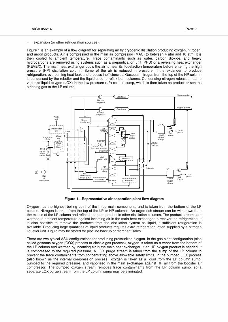
Figure 1 is an example of a flow diagram for separating air by cryogenic distillation producing oxygen, nitrogen, and argon products. Air is compressed in the main air compressor (MAC) to between 4 atm and 10 atm. It is then cooled to ambient temperature. Trace contaminants such as water, carbon dioxide, and heavy hydrocarbons are removed using systems such as a prepurification unit (PPU) or a reversing heat exchanger (REVEX). The main heat exchanger cools the air to near its liquefaction temperature before entering the high pressure (HP) distillation column. Some of the air is reduced in pressure in the expander to produce refrigeration, overcoming heat leak and process inefficiencies. Gaseous nitrogen from the top of the HP column is condensed by the reboiler and the liquid used to reflux both columns. Condensing nitrogen releases heat to vaporize liquid oxygen (LOX) in the low pressure (LP) column sump, which is then taken as product or sent as stripping gas to the LP column.
Adsorbers
Airinlet
Directcontactafter-
coolers
Adsorbers
Waste
AdsorbersLiquid
oxygenstorage
Liquidproduct
Liquid
nitrogenstorage
Liquidproduct
Nitrogen product
Oxygen product
Nitrogencompressor
Oxygen
compressor
Gas storage
Gas storage
Adsorbers Pumps
Pumps
Reflux
valves
Subcooler
Crudeargon
product
Mainair
compressor
Chiller
Wastechill
tower
Waste
vent
Waste
vent
Low
Expander
Highpressure
column
Liquidoxygen (alt)
Gaseousoxygen (alt)
Product liquidoxygen pump
Nitrogen liquefier unit
Prepurificationunit
pressurecolumn
Figure 1—Representative air separation plant flow diagram
Oxygen has the highest boiling point of the three main components and is taken from the bottom of the LP column. Nitrogen is taken from the top of the LP or HP columns. An argon-rich stream can be withdrawn from the middle of the LP column and refined to a pure product in other distillation columns. The product streams are warmed to ambient temperature against incoming air in the main heat exchanger to recover the refrigeration. It is also possible to remove the products from the distillation system as liquid, if sufficient refrigeration is available. Producing large quantities of liquid products requires extra refrigeration, often supplied by a nitrogen liquefier unit. Liquid may be stored for pipeline backup or merchant sales.
There are two typical ASU configurations for producing pressurized oxygen. In the gas plant configuration (also called gaseous oxygen [GOX] process or classic gas process), oxygen is taken as a vapor from the bottom of the LP column and warmed by incoming air in the main heat exchanger. If an HP oxygen product is needed, it is compressed to the required pressure. A LOX purge stream is taken from the sump of the LP column to prevent the trace contaminants from concentrating above allowable safety limits. In the pumped LOX process (also known as the internal compression process), oxygen is taken as a liquid from the LP column sump, pumped to the required pressure, and vaporized in the main exchanger against HP air from the booster air compressor. The pumped oxygen stream removes trace contaminants from the LP column sump, so a separate LOX purge stream from the LP column sump may be eliminated.
AIGA 056/14 PAGE 3
There are many other configurations of the ASU process that are specifically tailored for different products mixes and customer needs. A detailed discussion of these is beyond the scope of this publication.
4 Definitions
4.1 Publication terminology
4.1.1 Shall Indicates that the procedure is mandatory. It is used wherever the criterion for conformance to specific recommendations allows no deviation.
4.1.2 Should Indicates that a procedure is recommended.
4.1.3 May Indicates that the procedure is optional.
4.1.4 Can Indicates a possibility or ability.
4.2 Acid gas Air contaminants such as chlorine, NOx, and SOx that can form acid when combined with water.
NOTE—Acid gases can create corrosive conditions in brazed aluminum heat exchangers (BAHXs) and other equipment.
4.3 Adsorption Purification process in which one or more components from a gas or liquid is preferentially adsorbed onto a solid desiccant or other adsorbent.
NOTE—Typical adsorbents include:
– Molecular sieve—granular adsorbent (typically 13X) used in air PPUs for water, carbon dioxide, and hydrocarbon removal;
– Alumina—granular adsorbent typically used in air PPUs or dryers for water removal; and
– Silica gel—granular adsorbent typically used in cryogenic adsorbers for carbon dioxide and hydrocarbon removal.
4.4 Asphyxiation To become unconscious or die from lack of oxygen.
4.5 Blow out Maintenance or commissioning procedure in which a fluid, typically dry air, is blown through piping and equipment to eliminate dirt, moisture, or other contaminants.
4.6 Brazed aluminum heat exchanger (BAHX) An aluminum plate and fin heat exchanger consisting of corrugated sheets separated by parting sheets and an outer frame consisting of bars with openings for the inlets and outlets of fluids, equipped with headers and nozzles to connect to external piping.
NOTE—The approximate thickness of the corrugated sheets is 0.2 mm to 0.5 mm, while the parting sheets have thicknesses between 1.0 mm and 2.4 mm. More information is provided in AIGA 057, Safe Use of Brazed Aluminum Heat Exchangers for Producing Pressurized Oxygen [2].
4.7 Casing Outside walls of a coldbox or cryogenic piping duct. The cross section can be circular or rectangular.
4.8 Catalyst Material that helps promote a reaction but is not changed itself.
AIGA 056/14 PAGE 4
4.9 Cavitation This phenomenon occurs when the pressure of a liquid drops below the vapor pressure of the liquid at a certain temperature. At this point, liquid will vaporize, thereby creating vapor bubble. These bubbles can cause a pump to lose prime or suffer heavy vibration and damage.
4.10 Centrifugal Dynamic compressor or pump that works by accelerating a fluid in a rotating impeller with subsequent conversion of this energy into pressure.
4.11 Cleanup Removing trace contaminants from a stream or from process equipment.
4.12 Coldbox Structure that contains cryogenic distillation columns, other process equipment, piping, and insulation; can also refer to the cryogenic portion of an ASU.
4.13 Control system System that responds to input signals from the process, operator, or both and generates an output that causes the process to operate in the intended manner.
4.14 Crude argon purification system Warm equipment including compressors, catalytic reactors, heat exchangers, driers, and chillers used for removing oxygen from crude argon.
4.15 Cryogenic liquid
Liquid that is extremely cold, less than −130 °F (–90 °C).
4.16 Dead end boiling (pool boiling, pot boiling) The condition occurring in thermosyphon reboilers where, due to blockages, the flow of liquid is restricted within the channels of the reboiler, thereby reducing the removal of contaminants by the flushing action of the liquid. Also known as pool or pot boiling. This phenomenon can also occur in cavities and sections of piping where oxygen-enriched liquid can be trapped and vaporized by heat leak.
NOTE—This process is particularly hazardous when the oxygen-enriched liquid contains hydrocarbons that become concentrated during vaporization.
4.17 Differential temperature (∆∆∆∆T) Temperature difference between two streams in a heat exchanger, which is an indicator of the exchanger’s performance and efficiency.
4.18 Deriming Periodic preventive maintenance procedure where the process equipment is warmed up while simultaneously being swept with clean dry gas to remove any accumulated moisture, carbon dioxide, and atmospheric contaminants.
NOTE—Also known as defrosting, de-icing, and thawing.
4.19 Deoxidation or deoxo Catalytic removal of trace oxygen contaminant from a gas by a reaction with hydrogen, typically in warm argon production in ASUs.
4.20 Deoxo systems Catalytic-based system used in some argon refining systems to remove oxygen. Hydrogen is added to the crude argon stream and then reacts with oxygen to form water.
4.21 Distance piece Extended spacer, intermediate support, or carrier frame that isolates the process end of a pump or compressor from its motor or bearings to prevent migration of process fluid, oil, heat, or refrigeration.
AIGA 056/14 PAGE 5
4.22 Double block and bleed Piping or instrument arrangement that combines two block (or isolation) valves in series with a vent valve in between the block valves as a means of releasing pressure between the block valves with the intent to provide positive isolation.
4.23 Dry boiling Condition occurring where oxygen-enriched liquid enters cavities and sections of piping or equipment and is totally vaporized, thereby concentrating any less volatile contaminants by extremely high factors.
NOTE—Also known as dry vaporization.
4.24 Exothermic Reaction that produces heat.
4.25 Expander Machine that expands a fluid from higher to lower pressure thereby removing energy (work) and creating refrigeration.
4.26 Failsafe When a failure of a component of the system occurs, the resulting situation does not present a safety concern.
NOTE—One example is isolation valves closing when the plant air or power supply fails.
4.27 Filtering device Device that removes and retains particles from a liquid or gas stream.
NOTE—The particle size removed is dependent on the actual device design. The terms filter, screen, and strainer are sometimes used interchangeably; however, they can be classified by the particle size removed as follows:
– Strainer—device that removes and retains relatively coarse particles;
– Screen—device that removes and retains fine particles; or
– Filter—device that removes and retains very fine particles.
4.28 Fouling Blockage or surface coating with any contaminants in any plant equipment (e.g., heat exchanger, expanders, etc.) that can adversely affect its pressure drop or thermal performance.
NOTE—In an ASU, blocking or plugging is usually caused by frozen carbon dioxide, water, or hydrocarbons in cryogenic exchangers. Fouling is also a concern with heat exchangers within the cooling system.
4.29 Getter Reactive material that removes trace contaminants from a gas.
NOTE—Since the contaminant is chemically adsorbed by the getter, getters can be either consumed or regenerated.
4.30 Inert gas/Inert liquid Fluids that do not readily react with other materials under normal temperatures and pressures.
NOTE—Nitrogen, argon, and helium are examples of inert gases.
4.31 Inlet guide vanes Device on the inlet of a compressor that changes the capacity of the machine more efficiently than a suction throttling valve.
4.32 Inlet nozzle Device on the inlet of an expander that is part of the expansion process.
NOTE—Movable inlet nozzles can be used to adjust the capacity of the expander.
AIGA 056/14 PAGE 6
4.33 Instrumented system System composed of sensors (for example, pressure, flow, temperature transmitters), logic solvers or control systems (for example, programmable controllers, distributed control systems), and final elements (for example, control valves) designed to perform a specific function.
NOTE—For more information, see IEC 61511-1, Functional Safety–Safety Instrumented Systems for the Process Industry Sector—Part 1: Framework, Definitions, System, Hardware and Software Requirements [3].
4.34 Joule–Thomson (JT) expansion Process by which a fluid is expanded adiabatically (no work removed) from high pressure to lower pressure, usually through a valve.
NOTE—For gas applications in air separation plants, this results in a temperature drop.
4.35 Labyrinth Type of gas seal that uses a series of teeth to minimize leakage of the process fluid.
4.36 Lockout Condition where a device cannot be operated without a willful, conscious action to do so to ensure safety by positively isolating energy sources (pressure, electrical, temperature, and chemical).
NOTE—An example is when electricity is turned off and cannot be regained without removing a protective device such as a padlock from the actuating device. Another example is a valve where the handle is removed and stored securely until it is safe to operate the valve. A locked-out device shall be immediately tagged out.
4.37 Lower explosive limit (LEL) Lowest concentration of a flammable gas in an oxidant that will propagate when ignited.
NOTE—LEL is sometimes referred to as lower flammability limit (LFL).
4.38 Safety data sheet (SDS) Documents describing a material and its associated hazards mandated by the government and made available by the material supplier.
4.39 Net positive suction head (NPSH) Margin of difference (measured in height) between the actual pressure of a liquid flowing into a pump and the vapor pressure of the liquid.
4.40 Nitrogen NF Nitrogen that meets United States Pharmacopeia and National Formulary (USP–NF) requirements [4].
NOTE—See CGA G-10.1, Commodity Specification for Nitrogen, for additional information [5].
4.41 Nozzle Pipe connected to any vessel.
4.42 Oxygen-deficient atmosphere/nitrogen-enriched atmosphere Atmosphere in which the oxygen concentration by volume is less than 19.5%.
4.43 Oxygen-enriched atmosphere Atmosphere in which the oxygen concentration exceeds 23.5%.
4.44 Oxygen USP Oxygen that meets USP–NF requirements [4].
NOTE—See CGA G-4.3, Commodity Specification for Oxygen, for additional information [6].
4.45 Precipitate Formation of a solid from a liquid or vapor solution when the solubility limit for a component is exceeded.
AIGA 056/14 PAGE 7
4.46 Pressure relief device (PRD) Self-contained device designed to protect a vessel or piping from achieving pressures higher or lower (vacuum) than its design to prevent failure of the piping or vessel; includes safety relief valves and rupture disks.
4.47 Purge Elimination of an undesirable contaminant by displacement with another fluid.
NOTE—A nitrogen purge of process equipment prevents the contact of moisture with cryogenic equipment. LOX containing hydrocarbons is purged from the reboiler sump with clean LOX.
4.48 Reciprocating Positive displacement-type compressor, expander, or pump that uses pistons.
4.49 Regeneration Reactivation of a spent or loaded adsorbent vessel using a hot and/or LP gas.
4.50 Safe area Location where gases are vented safely to prevent harm to personnel or property.
NOTE—In a safe area, the surrounding materials should be compatible with the exhaust gas.
4.51 Safety instrumented system (SIS) System used to implement one or more functions necessary to prevent a hazard from arising and/or to mitigate its consequences.
NOTE—An SIS is composed of any combination of sensors (for example, pressure, flow, temperature transmitters), logic solvers or control systems (for example, programmable controllers, distributed control systems), and final elements (for example, control valves). Use of the term SIS implies IEC 61511 has been used to design, operate, and maintain the safety system [3].
4.52 Solubility Amount of a component that can remain dissolved in a liquid or vapor without precipitating out as a solid.
4.53 Structured packing Sheets of corrugated metal arranged in a distillation column to promote intimate contact between vapor flowing upward with liquid flowing downward.
4.54 Sump Bottom of a distillation column or other vessel that can contain a liquid inventory, hold-up, or reserve level.
4.55 Tagout Written notification that a piece of equipment is out of service and cannot be operated without clearance from authorized personnel.
NOTE—Equipment that has been tagged out typically has a paper tag attached directly to it indicating that the item is out of service.
4.56 Upper explosive limit (UEL) Highest concentration of a flammable gas in an oxidant that will propagate when ignited.
NOTE—UEL is sometimes referred to as upper flammability limit (UFL).
4.57 Work permits Procedural documents highlighting special safety considerations that are issued to allow work to commence in a specific location.
AIGA 056/14 PAGE 8
5 Health hazards
Some health hazards are directly associated with the compressed gas industry. Properties of certain gas products can subject personnel to extreme cold temperatures, oxygen-deficient (asphyxiating) atmospheres, or oxygen-enriched (increased fire risk) atmospheres. A basic knowledge of the gas properties and taking precautions, such as wearing protective equipment, minimizes the risks of these hazards. Refer to the producer's safety data sheets (SDS) for specific information on materials handled in air separation plants.
5.1 Cryogenic liquids
The products of a cryogenic air separation plant have associated hazards such as:
– Cryogenic injuries or burns resulting from skin contact with very cold vapor, liquid, or surfaces. Effects are similar to those of a heat burn. Severity varies with the temperature and time of exposure. Exposed or insufficiently protected parts of the body can stick to cold surfaces due to the rapid freezing of available moisture, and skin and flesh can be torn on removal;
– Risk of frostbite or hypothermia (general cooling of the body) in a cold environment. There can be warning signs, in the case of frostbite, while the body sections freeze. As the body temperature drops, the first indications of hypothermia are bizarre or unusual behavior followed, often rapidly, by loss of consciousness;
– Respiratory problems caused by the inhalation of cold gas. Short-term exposure generally causes discomfort; however, prolonged inhalation can result in effects leading to serious illness such as pulmonary edema or pneumonia; and
– Hazardous concentrations and/or reduced visibility can also occur at considerable distances from the point of discharge, depending on topography and weather conditions. Cold gases are heavier than air, tend to settle and flow to low levels, and can create a dense water vapor fog.
See CGA P-12, Safe Handling of Cryogenic Liquids, for additional details [7].
5.2 Gas products
Nitrogen and argon are simple asphyxiants and if present in sufficient quantity can reduce the oxygen in the local atmosphere below that required to support life. If there are any significant quantities of hydrocarbon contaminants, there can be some nausea, narcosis, or dizziness. Removal from exposure generally results in return to normal body and behavioral functions. Oxygen-enriched atmospheres increase susceptibility to ignition and combustibility rates can be many times that of normal atmospheres.
5.3 Asphyxiation
The normal oxygen concentration in air is approximately 21% by volume. Gas containing less than 19.5% oxygen constitutes a hazardous working environment as defined by Title 29 of the U.S. Code of Federal Regulations (29 CFR) Part 1910.146 [8]. The depletion of the quantity of oxygen in a given volume of air by displacement with an inert gas is a potential hazard to personnel (see CGA P-12, 29 CFR, CGA SB-2, and CGA SB-15) [7, 8, 9, 10]. Also see the U.S. Chemical Safety and Hazard Investigation Board materials on the hazards of nitrogen asphyxiation [11, 12, 13].
When the oxygen content of air is reduced to approximately 15% or 16%, the rate of burning of combustible materials significantly decreases. The flame of ordinary combustible materials including those commonly used as fuel for heat or light is extinguished. This can be the first indication of an oxygen-deficient hazard. Somewhat less than this concentration an individual breathing the atmosphere is mentally incapable of diagnosing the situation. The symptoms of sleepiness, fatigue, lassitude, loss of coordination, errors in judgment, and confusion are masked by a state of euphoria giving the victim a false sense of security and well-being. See Table 1 for other typical symptoms of oxygen-deficient atmospheres [9].
Human exposure to atmospheres containing 12% or less oxygen brings about unconsciousness without warning and so quickly that individuals cannot help or protect themselves. This is true if the condition is
AIGA 056/14 PAGE 9
reached either by immediate change of environment or by gradual depletion of oxygen. The individual's condition and degree of activity has an appreciable effect on signs and symptoms at various oxygen levels. In some cases, prolonged reduction of oxygen can cause brain damage even if the individual survives.
Areas where it is possible to have low oxygen content, particularly in process buildings and control rooms shall be well ventilated. Inert gas vents should be piped outside of buildings or to a safe area. Where an oxygen-deficient atmosphere is possible, special precautions such as installation of oxygen analyzers with alarms, ensuring a minimum number of air changes per hour, implementing special entry procedures, or a combination of these procedures shall be taken. In process buildings and control rooms, warning signs shall be posted at all hazard area entrances to alert personnel to the potential hazard of an oxygen-deficient atmosphere in accordance with OSHA requirements in 29 CFR Part 1910 [8]. Oxygen analyzer sensors shall be located in positions most likely to experience an oxygen-deficient atmosphere and the alarm shall be clearly visible, audible, or both at the point of personnel entry.
When an unsafe breathing atmosphere can occur, self-contained breathing apparatus or approved air lines and masks should be used, particularly when personnel enter enclosed areas or vessels. Breathing air should come from a verified source; a plant instrument air system shall not be used as a source of breathing air.
Personnel working in or around oxygen-deficient atmospheres shall use proper procedures including confined space entry.
DANGER: Entering an area with an oxygen-deficient atmosphere without following proper procedures will result in serious injury or death.
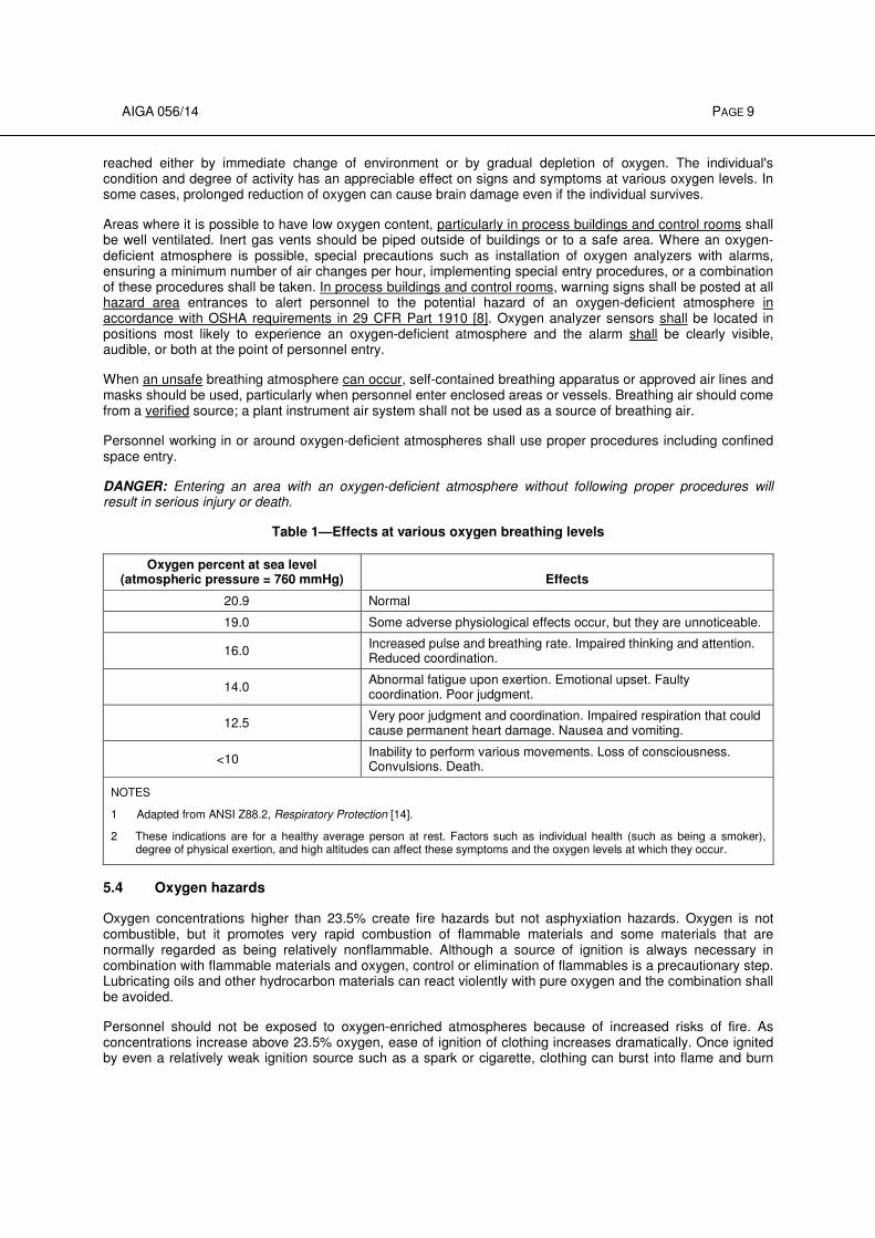
Table 1—Effects at various oxygen breathing levels
Oxygen percent at sea level (atmospheric pressure = 760 mmHg) Effects
20.9 Normal
19.0 Some adverse physiological effects occur, but they are unnoticeable.
16.0 Increased pulse and breathing rate. Impaired thinking and attention. Reduced coordination.
14.0 Abnormal fatigue upon exertion. Emotional upset. Faulty coordination. Poor judgment.
12.5 Very poor judgment and coordination. Impaired respiration that could cause permanent heart damage. Nausea and vomiting.
<10 Inability to perform various movements. Loss of consciousness. Convulsions. Death.
NOTES
1 Adapted from ANSI Z88.2, Respiratory Protection [14].
2 These indications are for a healthy average person at rest. Factors such as individual health (such as being a smoker), degree of physical exertion, and high altitudes can affect these symptoms and the oxygen levels at which they occur.
5.4 Oxygen hazards
Oxygen concentrations higher than 23.5% create fire hazards but not asphyxiation hazards. Oxygen is not combustible, but it promotes very rapid combustion of flammable materials and some materials that are normally regarded as being relatively nonflammable. Although a source of ignition is always necessary in combination with flammable materials and oxygen, control or elimination of flammables is a precautionary step. Lubricating oils and other hydrocarbon materials can react violently with pure oxygen and the combination shall be avoided.
Personnel should not be exposed to oxygen-enriched atmospheres because of increased risks of fire. As concentrations increase above 23.5% oxygen, ease of ignition of clothing increases dramatically. Once ignited by even a relatively weak ignition source such as a spark or cigarette, clothing can burst into flame and burn
AIGA 056/14 PAGE 10
rapidly. In oxygen-enriched atmospheres, the nap on clothing and even body hair and oil are subject to flash fire that spreads rapidly over the entire exposed surface.
Areas where it is possible to have high oxygen content shall be well ventilated. Gas vents shall be piped outside of buildings or to a safe area. Where an oxygen-enriched atmosphere is possible, special precautions such as installation of oxygen analyzers with alarms, ensuring a minimum number of air changes per hour, implementing special entry procedures, or a combination of these procedures shall be taken. Warning signs shall be posted at all entrances to alert personnel to the potential hazard of an oxygen-enriched atmosphere. For additional information on oxygen hazards see AIGA 005, (CGA P-39, Oxygen-Rich Atmospheres) [15].
5.5 Protective clothing and personal protective equipment
Guidelines for the selection of protective clothing can be found in AIGA 066, Selection of Personal Protective Equipment [16].
Protective clothing and personal protective equipment (PPE) serve to minimize the risk of injury due to fire hazards when working with oxygen or burns when working with cryogenic liquids or gases, but prevention of the hazard should be the primary objective.
Insulated or leather gloves (untanned and oil-free for oxygen service) shall be worn when handling anything that is cooled with cryogenic liquids and during cryogenic liquid loading and unloading activities. Gloves shall fit loosely so they can be removed easily if liquid splashes on or in them.
Safety glasses with side shields and a face shield shall be worn at all times when handling cryogenic liquids.
There are a number of flame retardant materials available such as Nomex® for work clothing, but they can burn
in high-oxygen atmospheres. There is an advantage in these materials as most of them would be self-extinguishing when removed to normal air atmospheres. All clothing should be clean and oil-free as these contaminants compromise the properties of these materials. Footwear should not have nails or exposed metallic protectors that could cause sparking.
If individuals inadvertently enter or are exposed to an oxygen-enriched atmosphere, they shall leave as quickly as possible. After exposure, avoid sources of ignition and do not smoke for at least one-half hour. Opening the clothing and slapping it helps disperse trapped vapors.
6 General plant considerations
6.1 Site selection
Air separation plant safety begins with a safety evaluation of the proposed plant site and the surrounding area. Generally, air separation plants are located in or near industrial areas as an adjunct to other industrial or chemical plants. A quantified risk assessment should be performed when plants are sited in proximity of hydrocarbon, corrosive, toxic, or other hazardous chemical sources. A plant installation should conform to the applicable industry consensus standards and shall adhere to all applicable local, state, provincial/territorial, and federal regulations. The plant operation should be reviewed for compatibility with the surrounding area. For example, the potential hazard of the cooling tower plume or cryogenic fog to nearby plants or vehicular traffic should be recognized. Adequate space should be provided for cryogenic liquid disposal. Environmental impacts of air separation plants are addressed in EIGA Doc 94, Environmental Impacts of Air Separation Units [17].
6.2 Safety factors in plant layouts
The use of valve pits, trenches, or both for cryogenic gas or liquid piping systems is not recommended because oxygen-enriched or oxygen-deficient atmospheres can occur very easily with such installations. If gas and liquid piping systems are installed in enclosed spaces, precautionary measures such as forced ventilation and alarm systems are recommended. Appropriate warning signs shall be posted.
Oxygen-enriched liquid drain lines should not be installed in a trench. Over time, trenches can accumulate oil, grease, and trash or other debris. If a leak in the line develops, a fire could result.
AIGA 056/14 PAGE 11
Caution should be taken to prevent liquid spills from entering floor drains or sewer systems. In areas where oxygen-enriched fluids are likely to contact the ground, asphalt ground cover shall be avoided, due to the potential for an energy release as a result of oxygen contact with hydrocarbons found in asphalt. For more information, see AIGA 085, Liquid Oxygen, Nitrogen, and Argon Cryogenic Tanker Loading Systems [18].
6.3 Materials of construction
The materials used in an air separation plant are exposed to a wide range of temperatures, pressures, and purities during operation. Materials shall be selected that are compatible with the expected conditions including normal operation, startup, shutdown, and process upsets.
For an oxygen system to operate safely, all parts of the system shall be reviewed for compatibility with oxygen under all conditions they encounter [19, 20]. The system shall be designed to prevent oxygen combustion by:
– selecting compatible material;
– operating within the designed pressure, temperature, and flow limits; and
– obtaining/maintaining cleanliness required for oxygen service.
Substitution of materials should not be made without first consulting a qualified engineering source. The vendor supplying the material may also be contacted for pertinent information.
6.3.1 Handling of aluminum packing during installation
Aluminum packing for columns shall be kept clean and dry during storage, transport, and installation.
A seal should be maintained to prevent water ingress into aluminum packing when stored outdoors or installed in the column. The packed column should be pressurized for transportation and be checked for pressure at delivery.
For more information regarding aluminum-structured packing, see AIGA 076, Safe Use of Aluminum-Structured Packing for Oxygen Distillation [21].
6.3.2 Metals
While common construction materials such as carbon steel, aluminum, and copper are used extensively in fabricating air separation plant components, it is important to remember that the use of these materials is selective and must be compatible with the operating conditions [17]. For example, common carbon steel is not
used at temperatures less than −20 °F (−29 °C) because at these temperatures it loses ductility, becomes brittle, and is subject to failure under impact conditions. Some metals that can be used safely in temperatures less than –20 °F (–29 °C) are austenitic stainless steel, aluminum, copper, Monel
®, brass, silicon-copper, and
9% nickel (ASTM A-353 steel). Reference information on the use of metals includes stainless steel, aluminum, copper, Monel
®, and brass [22-29].
Because of cost, carbon steel is generally used in temperatures greater than –20 °F (–29 °C) and at ambient temperature conditions for interconnecting process piping, storage vessels, and pipelines for either oxygen, air, or any of the inert gases such as argon or nitrogen [30, 31]. In special cases such as when moisture is present, stainless steel or other equally suitable metal should be considered to prevent corrosion.
If high surface area aluminum packing contacts water, hydrogen gas is generated by oxidation. Distillation columns packed with aluminum packing can cause explosions during fabrication or erection if water has entered the column and if the hydrogen gas generated forms an explosive mixture with air.
It is recommended to maintain a good tightness regarding water ingress for aluminum packing outdoor storage and for packed column on-site assembly. It is preferred to pressurize packed column for transportation and have a pressure check at delivery. It is recommended to have vents at high points of the column in order to be able to purge the hydrogen possibly accumulated and check the hydrogen content prior to working on the column.
AIGA 056/14 PAGE 12
6.3.3 Nonmetals
Nonmetallic materials such as gaskets, valve packing, insulation, and lubricants shall be checked to determine if they can be used for a particular application [32]. All factors associated with their use such as temperature, pressure, etc., shall be considered in deciding if a material can be used without decreasing the design safety integrity of the system. In an oxygen system the quantity of nonmetallic materials should be kept to a minimum and, where possible, be kept out of the direct flow of the gas stream.
6.4 Insulation—other than coldbox
Interconnecting process lines between components of an air separation plant operating at low temperatures require insulation to reduce process heat leak to an acceptable minimum and to prevent exposure of personnel to extremely low temperatures. The temperature and service of the line determine the type of insulation used.
Insulation for LOX lines or other lines that can come in contact with LOX should be noncombustible to protect against a possible reaction in the event of a liquid leak. Other process lines operating at temperatures warmer than the liquefaction point of air, approximately –313 °F (–192 °C), may be insulated with any commercially acceptable insulation that meets design requirements. Insulation that is noncombustible in air should be given preference. Oxygen-compatible binders, sealing compounds, and vapor barriers shall be used on lines carrying oxygen or oxygen-enriched gases or liquids.
Process lines operating at temperatures colder than the liquefaction point of air should be insulated with material compatible with oxygen. If the insulation cracks or deteriorates at these temperatures, air is diffused into the insulation, condenses against the surface of the pipe, and exposes the insulation material to oxygen-enriched liquid.
Personnel shall be protected from hot lines (higher than 140 °F [60 °C]) by either insulating the line or other barriers preventing access while the line is hot.
6.5 Cleaning
All materials for use in or interconnected with oxygen systems shall be suitably cleaned before the system is put into service. Mill scale, rust, dirt, weld slag, oils, greases, and other organic material shall be removed. An improperly cleaned line in oxygen service can be hazardous because particulates, greases, oils, and other organic materials can ignite a fire. Fabrication and repair procedures should be controlled to minimize the presence of such contaminants and thereby simplify final cleaning procedures. See CGA G-4.1, Cleaning Equipment for Oxygen Service; ASTM G93, Standard Practice for Cleaning Methods and Cleanliness Levels for Material and Equipment Used in Oxygen-Enriched Environments; and AIGA 012 Cleaning of Equipment for Oxygen Service [33, 34, 35].
Cryogenic process equipment and piping that handle inert fluids shall be cleaned for cryogenic service. This prevents foreign material from reaching other parts of the ASU.
6.6 Electrical requirements
Air separation plants are not typically considered hazardous locations for electrical equipment as defined by Article 500 of NFPA 70, National Electrical Code
® [36]. Therefore, in most cases, general purpose or
weatherproof types of electrical wiring and equipment are acceptable depending on whether the location is indoors or outdoors. Plants can have specific areas or equipment that necessitate special consideration due to handling of combustible or flammable materials. Such areas could include refrigeration systems using a hydrocarbon or ammonia refrigerant or an argon purification unit involving the use and handling of hydrogen.
In areas where high oxygen concentrations could be expected, electrical equipment with open or unprotected make-and-break contacts should be avoided. The simple expedient of locating electrical equipment away from areas where high oxygen concentrations can occur eliminates potential hazards in these situations.
Design considerations specified in the appropriate national, regional, and local codes shall be followed; industry guidelines regarding design considerations should also be considered. For further information, see NFPA 70,
AIGA 056/14 PAGE 13
(in the U.S.) or EIGA Doc 134, Potentially Explosive Atmosphere, EU Directive 1999/92/EC (in Europe) [36, 37].
6.7 Noise
The noise produced by compressors and their drives; by expansion turbines; by high gas velocities through piping and valves; and by pressure relief valves, vents, or bypasses shall be considered from the standpoint of potential hazard of hearing damage to employees. To assess the hazard, noise surveys should be performed after initial startup and when modifications are made that could change the noise emitted [38-42]. Noise abatement and use of personnel ear protection shall follow government guidelines (see 29 CFR Part 1910.95 [8]). Local, state, and provincial/territorial regulations can be more restrictive and shall be investigated.
Equipment operated under varying conditions can require additional noise surveys to identify the highest noise scenario. Periodic audiometric checks of personnel can be necessary depending on exposure times and noise levels.
7 Intake air quality
Air quality can have an impact on the air separation plant site selection and shall be evaluated. The air separation plant typically is located in an industrial area and thus a degree of contamination released from industrial and/or chemical plant operations can be expected to be present in the air. Trace contaminants in the atmospheric air, particularly hydrocarbons, have a direct bearing on the safe operation of an air separation plant. It is important to identify these contaminants and their levels of concentration in the atmospheric air. Short-term air quality analyses are not representative of long-term air contaminant levels. Changing site conditions can have an impact on air quality and should be evaluated periodically or when the surrounding industries change.
7.1 Contaminants
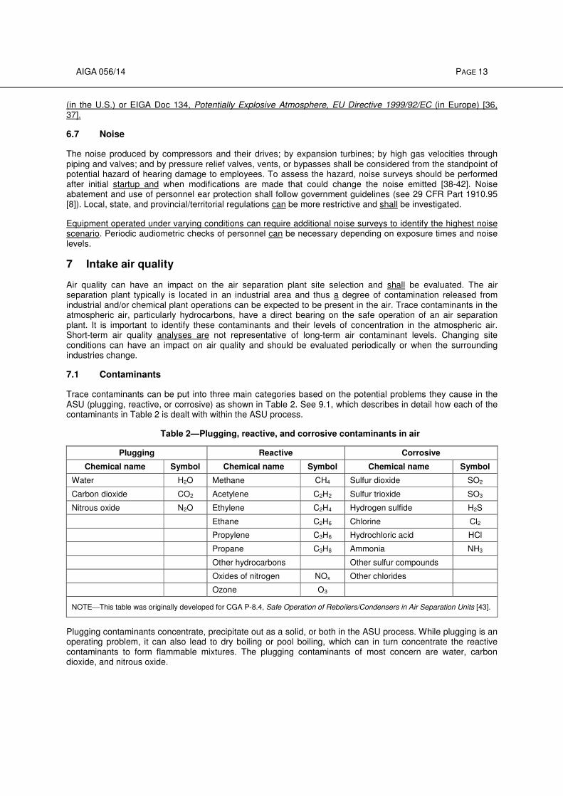
Trace contaminants can be put into three main categories based on the potential problems they cause in the ASU (plugging, reactive, or corrosive) as shown in Table 2. See 9.1, which describes in detail how each of the contaminants in Table 2 is dealt with within the ASU process.
Table 2—Plugging, reactive, and corrosive contaminants in air
Plugging Reactive Corrosive
Chemical name Symbol Chemical name Symbol Chemical name Symbol
Water H2O Methane CH4 Sulfur dioxide SO2
Carbon dioxide CO2 Acetylene C2H2 Sulfur trioxide SO3
Nitrous oxide N2O Ethylene C2H4 Hydrogen sulfide H2S
Ethane C2H6 Chlorine Cl2
Propylene C3H6 Hydrochloric acid HCl
Propane C3H8 Ammonia NH3
Other hydrocarbons Other sulfur compounds
Oxides of nitrogen NOx Other chlorides
Ozone O3
NOTEThis table was originally developed for CGA P-8.4, Safe Operation of Reboilers/Condensers in Air Separation Units [43].
Plugging contaminants concentrate, precipitate out as a solid, or both in the ASU process. While plugging is an operating problem, it can also lead to dry boiling or pool boiling, which can in turn concentrate the reactive contaminants to form flammable mixtures. The plugging contaminants of most concern are water, carbon dioxide, and nitrous oxide.
AIGA 056/14 PAGE 14
Reactive contaminants can concentrate within the ASU and form flammable mixtures with oxygen or enriched air. The most important reactive contaminants in air are methane, ethane, ethylene, acetylene, propane, and propylene. The other higher boiling point hydrocarbons are typically treated together. Hydrocarbon aerosols from smoke and haze are a special type of reactive contaminant and are discussed in 7.5. NOx and ozone are also reactive, but are not a major concern in properly operated ASUs. For more information, see AIGA 035 [43].
The previously discussed contaminants concentrate in oxygen. Hydrogen and carbon monoxide concentrate in nitrogen, waste nitrogen product, or both and are generally not safety hazards.
Corrosive contaminants (acid gases and ammonia) can react with equipment and piping causing operating problems and impacting equipment life. Since this publication is primarily dealing with safety, these contaminants are not discussed in detail.
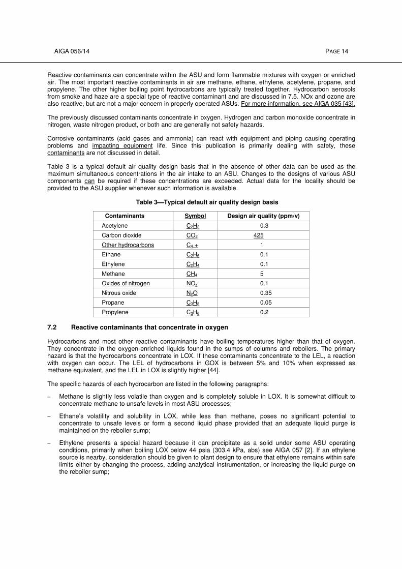
Table 3 is a typical default air quality design basis that in the absence of other data can be used as the maximum simultaneous concentrations in the air intake to an ASU. Changes to the designs of various ASU components can be required if these concentrations are exceeded. Actual data for the locality should be provided to the ASU supplier whenever such information is available.
Table 3Typical default air quality design basis
Contaminants Symbol Design air quality (ppm/v)
Acetylene C2H2 0.3
Carbon dioxide CO2 425
Other hydrocarbons C4 + 1
Ethane C2H6 0.1
Ethylene C2H4 0.1
Methane CH4 5
Oxides of nitrogen NOx 0.1
Nitrous oxide N2O 0.35
Propane C3H8 0.05
Propylene C3H6 0.2
7.2 Reactive contaminants that concentrate in oxygen
Hydrocarbons and most other reactive contaminants have boiling temperatures higher than that of oxygen. They concentrate in the oxygen-enriched liquids found in the sumps of columns and reboilers. The primary hazard is that the hydrocarbons concentrate in LOX. If these contaminants concentrate to the LEL, a reaction with oxygen can occur. The LEL of hydrocarbons in GOX is between 5% and 10% when expressed as methane equivalent, and the LEL in LOX is slightly higher [44].
The specific hazards of each hydrocarbon are listed in the following paragraphs:
– Methane is slightly less volatile than oxygen and is completely soluble in LOX. It is somewhat difficult to concentrate methane to unsafe levels in most ASU processes;
– Ethane’s volatility and solubility in LOX, while less than methane, poses no significant potential to concentrate to unsafe levels or form a second liquid phase provided that an adequate liquid purge is maintained on the reboiler sump;
– Ethylene presents a special hazard because it can precipitate as a solid under some ASU operating conditions, primarily when boiling LOX below 44 psia (303.4 kPa, abs) see AIGA 057 [2]. If an ethylene source is nearby, consideration should be given to plant design to ensure that ethylene remains within safe limits either by changing the process, adding analytical instrumentation, or increasing the liquid purge on the reboiler sump;
AIGA 056/14 PAGE 15
– Acetylene is a very hazardous reactive contaminant. Because acetylene has a low solubility in LOX, if it enters the coldbox it concentrates in LOX and precipitates out as a solid at concentrations as low as 4 ppm to 6 ppm (depending on the LOX pressure). The solid is relatively unstable and requires little energy to ignite. ASUs equipped with PPUs remove all of the acetylene from the air so none enters the coldbox. Plants equipped with REVEX do not remove acetylene from the incoming air and shall deal with it in the coldbox, typically by using cryogenic adsorbers;
– Propane is a relatively hazardous hydrocarbon because of its low volatility relative to oxygen and its ability to form a second liquid phase if its concentration is high enough. At low pressures, the second liquid phase forms before its concentration in LOX reaches the LEL. This second liquid phase of relatively pure propane could then react with the oxygen-rich phase, if ignited. Propane is not removed by the REVEX and is only partially removed by the PPU; the remainder shall be removed by liquid purge;
– Propylene is similar to propane in that it forms a second liquid phase in LOX if its concentration is high enough. This second liquid phase is reactive. Propylene, however, is removed relatively easily either by PPUs or cryogenic adsorption;
– Other hydrocarbons are the higher boiling point hydrocarbons (C4+). As the molecular weight increases, the solubility in LOX decreases. However, these are dealt with relatively easily by all trace contaminant-removal systems provided that these systems are operated properly;
– NOx can react with oxygen, but is removed either by the PPU or cryogenic adsorption. NOx compounds are primarily nitric oxide and nitrogen dioxide in atmospheric air and are the by-products of incomplete combustion. If they enter the coldbox, nitric oxide and nitrogen dioxide form increasingly higher molecular weight NOx compounds (nitrogen trioxide, dinitrogen tetraoxide, and dinitrogen pentoxide), which can then precipitate and plug equipment. At cold temperatures, NOx compounds can react with any unsaturated dienes found in REVEXs to form explosive gums [45, 46, 47]; and
NOTE—NOx (nitric oxide and nitrogen dioxide) are different compounds than nitrous oxide.
– Ozone is unstable and decomposes to oxygen-releasing heat, which is a potential hazard. Ozone is removed either by PPU or cryogenic adsorption.
7.3 Reactive contaminants that concentrate in nitrogen
Hydrogen and carbon monoxide have boiling points lower than oxygen and thus concentrate in nitrogen. The concentration factor is typically only 2 times to 10 times, so they remain at low ppm concentration. Hydrogen and carbon monoxide are a purity issue when ultra high purity nitrogen is produced. Carbon monoxide is also an issue when nitrogen NF is produced. They can be removed by other means such as front-end catalytic oxidation or nitrogen purification.
7.4 Plugging components
Characteristics of the specific plugging components are as follows:
– Water is very insoluble in cryogenic fluids and shall be removed before reaching the distillation columns. Water is removed in the REVEX or PPU;
– Carbon dioxide is relatively insoluble in LOX and is removed by the PPU, REVEX, or cryogenic adsorption. Reboiler liquid purge flows assist in maintaining carbon dioxide concentrations below the safe limit in the reboiler sump, see AIGA 035 [43]; and
– Nitrous oxide is relatively insoluble in LOX; however, it is more soluble than carbon dioxide. Therefore, for most applications, no nitrous oxide removal is required. It is partially removed by standard PPUs but special designs of the PPU can increase the removal efficiency. It is also removed by cryogenic adsorption. Reboiler liquid purge flows assist in maintaining nitrous oxide concentrations below the safe limit in the reboiler sump [43, 48].
NOTE—NOx (nitric oxide and nitrogen dioxide) are different compounds than nitrous oxide.
AIGA 056/14 PAGE 16
The solubility limits of mixtures of nitrous oxide and carbon dioxide in liquid cryogens are lower than their single component limits when both are present because they form a solid solution, see 12.4.
For more information about plugging compound accumulation, see AIGA 057 [2].
7.5 Haze and smoke from fires
Haze and smoke from forest fires, burning farmland, or other biomass combustion can create higher than normal hydrocarbon concentrations in the atmosphere.
An analysis of one fire showed that emissions consisted of:
– Vapor components of n-alkanes, aromatics, and some oxygen-containing compounds of C3 to C21 hydrocarbons; and
– Aerosols composed of droplets of 0.1 µ to 2 µ diameter, mainly C8 to C36 hydrocarbons [49].
Concentrations of hydrocarbon-rich vapor and aerosols that do not exceed the design limits of the plant are not a concern for ASU safety.
Only the vapor compounds are adsorbed by a PPU; however, the aerosols are typically too small to be retained
by inlet air or PPU dust filters, which typically capture particles 2 µ to 5 µ and larger. The aerosols can accumulate in the reboiler sump and become a significant hazard unless addressed.
If an ASU has the potential to have high amounts of aerosols in the ambient air exceeding the plant design limits for extended periods of time, the following items should be considered:
– Use a high efficiency filter to remove particles larger than 0.1 µm to 0.4 µm. The filter could be placed on the main air compressor inlet or on the prepurifier outlet; and
– Install/utilize particle counters to alert operating staff to a potential hazard.
When fire events occur, the following operating measures should be considered:
– If an ASU runs during a short period of high haze, ensure that all safety measures are being followed (e.g., reboiler submergence, LOX removal from the reboiler sump, etc.);
– Attention should be paid to ensure that solids such as carbon dioxide and nitrous oxide are not precipitating from oxygen-rich fluids. Monitor heat exchangers and piping systems for increases in pressure drop or decreased heat transfer performance. These are indications that solids might be precipitating; and
– Consider the manufacturer’s and operating company’s criteria to determine if an ASU should be shut down in a high haze environment.
An overview of haze and some of the potential ASU safety problems can be found in “Hydrocarbon Haze and ASU Safety” [50]. Hydrocarbons from forest fire haze contributed to a large ASU explosion, as detailed in “Investigation of an Air Separation Unit Explosion” [49].
NOTE—Consult the manufacturer for guidance as to what constitutes a significant haze. In the absence of any guidelines, a
PM10 threshold of 150 µgm/m3 may be used. PM10 is the mass of particles less than 10 µm diameter contained in 1 m3 of air. This is measured by many environmental regulating agencies throughout the world.
7.6 Contaminant sources
Airborne contaminants originate from numerous sources. Vents, stacks, flares, swampy areas, process leaks, natural gas heater emissions, exhausts from internal combustion engines, machinery lubrication system vents, landfills, and forest or field fires are the most common sources. Chemical and petroleum processes on adjoining properties and other processes within the air separation plant site shall be carefully examined as possible contamination sources.
Acetylene cylinders shall not be stored or used near the air intake of an operating MAC.
AIGA 056/14 PAGE 17
Signs should be posted near air compressor intakes prohibiting the parking and running of internal combustion engines or welding machines in the area. There have been incidents where the exhausts from nearby railroad diesel locomotives have been attributed to the appearance of acetylene in main condenser liquids.
7.7 Identification of contaminants
Contaminants can be identified by analyzing the ambient air. Table 3 provides a default air quality design basis for a typical industrial environment, which can be used if no other information is available.
7.8 Location of air intake
The distance that the air compressor intake shall be kept away from any potential source of airborne contaminants depends on the plant's capability for removing them to avoid hazardous concentrations within the ASU as well as wind velocity and other weather conditions that can affect contaminant dilution and dispersal.
Elevating the air intake can take advantage of wind velocity and other weather conditions that can affect contaminant dilution and dispersal. In the extreme case, two air intakes can be located so that if the air at one intake is contaminated, the alternate intake is either upwind or crosswind from the sources of contamination.
7.9 Monitoring intake air
Analysis of the intake air should be conducted when the likelihood of atmospheric air contamination is high. Conditions around a plant can change over time leading to an increased likelihood of atmospheric air contamination. If these changes negatively affect the ambient air, an analysis of the intake air should be completed. Analytical methods can vary from periodic determination of total hydrocarbon concentrations to continuous analysis for both the identification and concentration level of each individual hydrocarbon. If deemed necessary, the type and frequency of analysis method shall be determined specifically for each plant, taking into consideration the process design of the plant and the environment in which it will be operated.
At locations where continuous analysis is performed, contaminant data should be recorded. Records should be reviewed periodically to determine whether any trends are developing. Any appreciable increases in contamination levels should be investigated and addressed.
An analyzer, which normally monitors the intake air, may be shifted to the reboiler sump liquid or product LOX to periodically analyze that liquid for contaminant concentration.
Air separation plants located at sites where such a danger exists and where the operation is unattended or automated should include a control system function to shut down the ASU when the contamination level is high. For additional information on the design and operation of unmanned gas plants, see AIGA 028 Unmanned Air Gas Plants—Design and Operation [51].
8 Compressors
This section lists the types of compressors used for ASUs, their auxiliary systems, and special application considerations. The two major types of compressors used are dynamic or turbo machines, which include axial and centrifugal compressors, and positive displacement machines, which include reciprocating, diaphragm, rotary, and screw types.
For more information on safety standards for compressors, see ASME B19.1, Safety Standard for Air Compressor Systems, and ASME B19.3, Safety Standard for Compressors for Process Industries [55, 53].
8.1 Axial compressors
Axial compressors are commonly used for the MAC on large ASUs. When axial compressors are used, consideration should be given to the dynamic performance characteristics of the compressor with particular emphasis on surge conditions. A rigorous torsional and lateral critical review of the entire compressor-gear-drive system is required. The use of one or more rows of variable stator blades for controlling compressor capacity is common. Consideration should be given to the design of the stator blade actuating mechanism with emphasis on the prevention of rusting and dirt deposits on it, which can cause binding in operation. Special
AIGA 056/14 PAGE 18
consideration should also be given to the first three rows of rotating blades where moisture can cause rusting and imbalance. The compressor casing should be designed for the maximum pressure that can be reached under any condition of operation including surge.
8.2 Centrifugal compressors
Centrifugal compressors are widely used for MAC duty as well as oxygen product, nitrogen product, and nitrogen recycle service. As with the axial machine, consideration should be given to the performance characteristics compared to the expected plant operating requirements. A review of the torsional and lateral criticals with the gear and driver included should be performed for each installation. Compressor casings should be designed for the maximum pressure that can be reached under any condition of operation including surge. Capacity control is typically accomplished by variable inlet guide vanes on at least the first stage.
8.3 Other dynamic compressor considerations
8.3.1 Antisurge control
All axial and centrifugal compressors shall be equipped with an automatic antisurge control system with either a recirculation or blow-off valve. The response time of the antisurge system should be consistent with the dynamics of the process system.
8.3.2 Check valve
A check valve shall be installed in the discharge line after the vent or recirculation bypass connection of all dynamic compressors to prevent surge and reverse rotation. In wet gas service, moving parts should be made of nonrusting material to ensure proper operation of the valve.
8.3.3 Monitoring devices
The manufacturer’s recommendations shall be followed for monitoring operating parameters, alarms, and shutdowns.
Proximity-type vibration probes and monitors shall be installed on all axial or centrifugal compressor installations to measure shaft movement and actuate alarm and shutdown systems. Axial displacement probes should also be considered as additional protection. The data from these sensors should be periodically analyzed. If the readings are abnormal or if the compressor shuts down on high vibration, careful review of the data by experts can provide insights into the cause of the high vibration readings. The compressor should not be restarted until the cause of the excessive vibration reading is resolved.
Motors driving dynamic compressors can be overloaded under certain winter or abnormal operating conditions. Consideration should be given to amperage limit controllers overriding the capacity control of the machine.
8.3.4 Stage seals
All dynamic or turbo machinery compressors use shaft stage seals to minimize or eliminate the outward leakage of the pressurized process gas to the atmosphere and to prevent oil contamination of the process gas. Stage seals are also used to control the leakage of process gas between compressor stages on a common shaft. The most common type of shaft stage seal is the labyrinth sealing system where some leakage can be tolerated. Depending on the process requirements, hazards, or both involved with the gas being compressed, other types of seals can be used. Examples of other types of seals are:
– Single or multi-buffered labyrinth seals permit the injection of a buffer gas between the labyrinths for maximum process gas containment and are used on oxygen and nitrogen compressors. Nitrogen is the customary buffer gas used;
– Floating carbon ring seals are used for minimum process gas leakage and are used on nitrogen and some air compressors. Floating carbon ring seals find wide application where the compressed gas pressures are high and the leakage would be costly; or
AIGA 056/14 PAGE 19
– Dynamic dry gas seals are used for minimum process gas leakage during operation and near-positive sealing during shutdown. Dynamic dry gas seals are used where process gas leakage can be hazardous or costly.
Labyrinth seals also are used to prevent the migration of lubricating oil from the compressor bearing housings into the atmosphere or the process gas. A slight vacuum is normally maintained on the compressor lube oil reservoir to ensure that an inward flowing air buffer seal exists at the bearing shaft seal.
8.4 Reciprocating compressors
Reciprocating compressors are widely used for oxygen, nitrogen, crude argon product, and HP air service. The two types of reciprocating compressors are nonlubricated cylinder compressors and lubricated cylinder compressors. Some factors that affect the selection of a reciprocating compressor are:
– gas composition;
– compression ratios;
– tolerance of the gas to oil contamination; and
– maintenance requirements.
8.4.1 Nonlubricated cylinders
Several materials are available for nonlubricated piston rings, rider rings, and rod packings. Most commonly used materials are polytetrafluoroethylene (Teflon
®) and filled Teflon. Piston rods and cylinder walls should be
inspected for abnormal wear, scratches, and rubs, not only at commissioning but also during the operating life of the equipment. Compressor valves in nonlubricated service can have Teflon or equivalent wear buttons or guides. For nonlubricated reciprocating oxygen compressors, rod packing can be water cooled.
8.4.2 Oil-lubricated cylinders
The compressor manufacturer recommends the specifications for the cylinder lubricant, which depends on the expected temperatures, cylinder size, piston speed, and the characteristics of the gas compressed. Different lubricants are used for cylinder and running gear (crankcase) lubrication. The lubricants for the cylinders and the crankcase shall not be interchanged or mixed. If mineral oil is used in the crankcase, it shall be tested periodically to determine if migration of synthetic oil from the cylinders along the piston rods and into the crankcase has occurred. If the concentration of synthetic oil exceeds the manufacturer’s recommendation, the crankcase oil shall be changed.
If mineral oil is used in air service, it is important to check periodically for carbon buildup in equipment and piping downstream of the compressor. Valve pockets and piping should be inspected shortly after startup to determine if oil feed rates are within design specifications. Excessive feed rates cause higher carbon buildup and possible liquid slugging.
If an existing compressor is converted from mineral oil to synthetic oil, both the compressor and the lubricant manufacturers should be consulted. The complete interior of cylinders, lubricators, intercoolers, and interconnecting piping shall be thoroughly cleaned and, in cases where the paint is incompatible with the synthetic lubricant, the existing interior paints should be removed. Plastic sight glasses on lubricators shall be replaced with glass. All rubber and neoprene gaskets shall be replaced with Teflon or filled Teflon. The crankcase and piston rod scraper rings shall be effective in both directions so that the synthetic cylinder lubricant cannot get into the crankcase that still uses mineral oil.
The cylinder lubrication rate should be the minimum necessary to wet the entire cylinder wall. Higher rates result in excessive carbon deposits on valves and in passages. There should be no pools of oil in valve chambers or interconnecting piping. Depending on the type of oil and the lubricator, one drop from the lubricator per minute per cylinder is generally sufficient for 1000 ft
2 (92 m
2) of cylinder surface swept per
minute. The compressor manufacturer suggests feed rates for each cylinder at startup, but subsequent inspections should guide further adjustments.
AIGA 056/14 PAGE 20
Oil removal from reciprocating compressors starts with the separators and traps after each stage intercooler and at the separator following the final stage aftercooler. Much of the oil vaporized into the gas stream condenses into a mist in the coolers, forms droplets in the separators, and drains. Some oil vapor is still in the gas stream that might have to be removed by other methods. The oil trap(s) should be periodically drained to prevent accumulation that can become a source of fuel for a compressor fire. Drained oil shall be handled in accordance with government environmental regulations.
For oil-lubricated compressors, downstream equipment is needed to remove oil from the process gas stream. This typically consists of mechanical separators followed by filters, coalescers, adsorptive beds, or any combination of these. These systems shall be maintained to ensure complete oil removal. This is particularly critical when the compressor is the MAC and oil carryover would result in coldbox fouling.
8.4.3 Water-lubricated cylinders
Soap-water-lubricated or water-lubricated compressor cylinders should be operated in accordance with the manufacturer’s instructions. Detergent-type soap shall never be used. Distilled or demineralized water should be used to avoid heavy soap deposit on the valves.
8.4.4 Halogenated oil-lubricated cylinders
Halogenated oil-lubricated compressor cylinders should be operated in accordance with the manufacturer’s instructions. Halogenated lubricants are available that are safe for use in oxygen compressor systems.
8.4.5 Distance pieces
Single-compartment, open distance pieces are acceptable in air or inert gas compressor service. Distance-piece design should accommodate one full stroke length plus the space needed for a slinger on the piston rod so no portion of the rod that is wetted with the crankcase oil comes in contact with the parts in contact with the process gas. In high purity gas service, the cylinder-end distance piece should be pressurized to prevent contaminating the process gas with air.
8.4.6 Labyrinth seal compressors
Vertical labyrinth seal compressors are used in both oxygen and inert gas service and depend on a closely fitted labyrinth grooved piston for sealing. Carbon labyrinth rings are used in the rod packing case.
8.4.7 Capacity control
On reciprocating compressors, capacity control is normally accomplished by clearance pockets, valve lifters, valve unloaders, or automatic recirculation valves. Clearance pockets should be selected to limit the capacity reduction in one end of a cylinder to not more than 50% to prevent excessive recompression of gas and resultant overheating. Multi-stage units require matching of capacity reduction on all stages to prevent high discharge temperatures caused by unbalanced compression ratios. Clearance pockets, valve lifters, and valve unloaders shall not be used in reciprocating oxygen compressors.
8.4.8 Pulsation bottles
In the case of lubricated compressors, pulsation bottles shall be inspected periodically for carbon buildup and cleaned when necessary.
8.4.9 Special consideration for nitrogen service
In operating a lubricated reciprocating nitrogen compressor, it is possible to accumulate a quantity of unoxidized carbonaceous material. Explosions have occurred in these systems when the oxygen content of the gas increases to significantly higher than normal. The nitrogen system should be monitored to detect a significant increase in oxygen concentration. Lubricated reciprocating machines used for long periods in nitrogen or any other inert gas service shall be inspected and cleaned of wear particles or lubricant deposits before being placed in air service.
AIGA 056/14 PAGE 21
8.4.10 Monitoring devices
The manufacturer’s recommendations regarding the location of installation for indicators, remote alarm, or shutdown devices should be considered.
A vibration switch should be installed on all reciprocating compressors. On large units, at least one switch should be considered for every two compression throws.
8.5 Diaphragm compressors
Diaphragm compressors are normally used when high pressures and contaminant-free compression are required. The running gear, cooling, and monitoring requirements are similar to the reciprocating compressor requirements. Consideration should be given to systems for detecting leaks in the diaphragm.
When a diaphragm compressor is used in oxygen service, the hydraulic fluid under the diaphragm should be a soap-water solution or halogenated fluid that is oxygen compatible. As diaphragms can develop fatigue cracks that allow the hydraulic fluid to come in contact with the oxygen gas, a detection device to detect fluid leakage is recommended.
8.6 Rotary positive displacement compressors
Rotary positive displacement compressors are typically used for LP applications in air and inert gas service. They should be provided with seals to prevent oil contamination of the process gas.
8.7 Refrigerant gas compressors
Both centrifugal and positive displacement machines are used in refrigerant service. Attention should be given to the operation of the oil separation devices to avoid mixing oil with the refrigerant. The correct operation of the unloaders, hot gas bypass, or both shall prevent liquid refrigerant from entering the compressor under low load conditions, which can result in severe equipment damage. Change of service to an alternative refrigerant shall be done in accordance with manufacturer’s recommendations.
8.8 Screw compressors
Screw compressors are used in air, inert, or refrigerant service and are either oil-lubricated or nonlubricated. Oil-lubricated compressors require downstream equipment to remove oil from the process gas stream. This typically consists of mechanical separators followed by filters, coalescers, adsorptive beds, or any combination of these. These systems shall be maintained to ensure complete oil removal. This is particularly critical when the screw compressor is the MAC and oil carryover would result in coldbox fouling.
8.9 Lubrication systems
The lubrication system should be designed for the individual requirements of the affected equipment. This system includes an oil reservoir, cooler, filters, pumps, and auxiliary control equipment.
8.9.1 Pumps
As a minimum, the lubrication system should be equipped with a main oil pump and a standby oil source. The main pump can be shaft drive, motor drive, steam drive, or pneumatic drive. The standby source can be a motor drive, steam drive, or pneumatic drive pump or a pressurized oil accumulator system. If two pumps are used, they should not be dependent on the same source of power. Each pump should have a strainer installed at its inlet and a check valve at its discharge. When an accumulator reservoir system is used, it should be automatically activated to supply oil for compressor bearings during coastdown should the main pump fail.
The accumulator pressure should be checked during scheduled maintenance of the compressor.
Provisions should be made to allow for adequate lubrication of dynamic compressors during loss of the main lubrication pump. These alternatives include:
AIGA 056/14 PAGE 22
– reverse rotation protection on the main oil pump;
– bladder-type oil accumulators sized to supply oil for coastdown; and
– overhead oil tanks sized to supply oil for coastdown.
8.9.2 Filters
Oil filters should remove particles larger than 10 µ and should be replaced whenever the manufacturer’s maximum allowable differential pressure is reached. Dual oil filters can be used to allow replacement of the filter elements during normal operation. These units are piped in parallel using continuous flow transfer valves on the suction and discharge. Vent and fill valves should be included in each filter housing to allow for the controlled addition of oil to a newly replaced unit, and drain valves should be provided to facilitate filter removal.
8.9.3 Coolers
The heat exchangers shall be designed to TEMA, ASME, or other industry or national codes as required [54, 55]. The lube oil pressure should be higher than the cooling medium to prevent water leakage into the oil during operation.
8.9.4 Reservoir
The volume of the reservoir shall be of sufficient size to contain all of the oil in the lubrication system (including overhead tanks, accumulators, and piping) when the oil drains back into the reservoir during shutdown. This container shall be sealed to prevent the entry of dirt and moisture into the oil.
8.9.5 Control and instrumentation
On large compressors, dual lube oil pressure sensors should be provided in the lube oil pressure system. This instrumentation should start up the auxiliary oil pump, shut down the compressor, and provide a permissive start signal.
Instrumentation should be included to detect the following conditions:
– low oil pressure (alarm and shutdown);
– high oil temperature (alarm);
– low sump lube oil level (alarm and lube oil heater shutdown);
– high oil filter differential pressure (alarm);
– low lube oil temperature (permissive start only); and
– standby pump operation (alarm).
A pressure relief valve shall be included after each positive displacement pump, and a pressure-regulating valve should be used to control system pressure. Pressure sensing for the regulating valve should be in the oil supply to the equipment.
An oil temperature control valve should be included around the oil cooler to maintain the design supply temperature.
8.9.6 Lubricants for running gear, gearcase, and crankcase
This section describes lubricants to be used for running gear, gearcases, and crankcases for all types of compressors. Lubricants for reciprocating compressor cylinders are described in 8.4.2.
Lubricating oil should be consistent with the manufacturer's recommendations. These oils can be either a mineral oil or a synthetic blend.
AIGA 056/14 PAGE 23
Testing of lube oil should be performed on a regular schedule. Minimum tests to be conducted should include:
– spectro chemical analysis—chemical content;
– physical properties analysis—particulate count, percent weight, and volume;
– viscosity;
– neutralization number testing—acid content; and
– water content.
8.10 Coolers and separators
Coolers shall be designed to TEMA, ASME, or other national or industry codes as required [54, 55]. Design consideration should be given to chemical contaminants in the atmosphere that can cause acidic conditions in air compressor intercoolers and aftercoolers, resulting in corrosion.
8.11 Suction filters or screens
Every compressor shall have a suction filter or screen to prevent foreign particles from entering the compressor. The filter or screen shall be in accordance with the manufacturer’s recommendations.
8.11.1 Air inlet filters
Two-stage filtration shall be provided. For very small compressors, one-stage filtration may be provided. In severely dirty environments, additional filtration should be considered. Insect screens, freeze protection, and rain/snow hoods shall be provided when necessary.
A differential pressure indicator and alarm are recommended. Large filter houses shall be protected against excessive differential pressures that could cause collapse as a result of filter blockage.
8.11.2 Other suction screens
Mesh size should be in accordance with the compressor manufacturer's recommendation. The screen should be designed to withstand full operating pressure across it at that point of the system. A differential pressure device can be put across this filter to determine the need for cleaning.
8.11.3 Filter considerations for reciprocating compressors
The selection and design of suction filters for reciprocating compressors shall address the effect of pulsating gas flow.
8.12 Special considerations for oxygen service
There are special considerations for safe design and operation of an oxygen compressor. These include:
– materials of construction;
– isolation and vent valve location and controls;
– clearance pockets for reciprocating compressors; and
– stage discharge temperature.
Details of considerations for oxygen service are given in CGA G-4.1, ASTM G93,AIGA 021, CGA G-4.6, AIGA 048, AIGA 071, and AIGA 012 [33,34, 56, 57, 58, 59, 35].
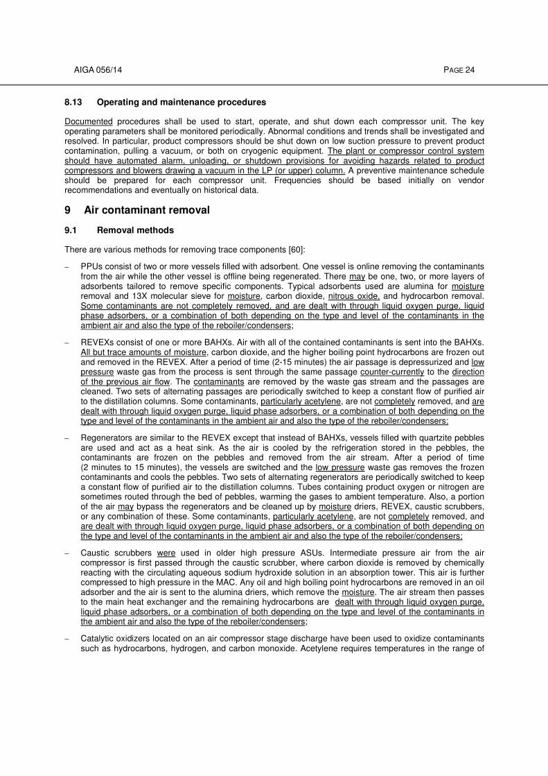
AIGA 056/14 PAGE 24
8.13 Operating and maintenance procedures
Documented procedures shall be used to start, operate, and shut down each compressor unit. The key operating parameters shall be monitored periodically. Abnormal conditions and trends shall be investigated and resolved. In particular, product compressors should be shut down on low suction pressure to prevent product contamination, pulling a vacuum, or both on cryogenic equipment. The plant or compressor control system should have automated alarm, unloading, or shutdown provisions for avoiding hazards related to product compressors and blowers drawing a vacuum in the LP (or upper) column. A preventive maintenance schedule should be prepared for each compressor unit. Frequencies should be based initially on vendor recommendations and eventually on historical data.
9 Air contaminant removal
9.1 Removal methods
There are various methods for removing trace components [60]:
– PPUs consist of two or more vessels filled with adsorbent. One vessel is online removing the contaminants from the air while the other vessel is offline being regenerated. There may be one, two, or more layers of adsorbents tailored to remove specific components. Typical adsorbents used are alumina for moisture removal and 13X molecular sieve for moisture, carbon dioxide, nitrous oxide, and hydrocarbon removal. Some contaminants are not completely removed, and are dealt with through liquid oxygen purge, liquid phase adsorbers, or a combination of both depending on the type and level of the contaminants in the ambient air and also the type of the reboiler/condensers;
– REVEXs consist of one or more BAHXs. Air with all of the contained contaminants is sent into the BAHXs. All but trace amounts of moisture, carbon dioxide, and the higher boiling point hydrocarbons are frozen out and removed in the REVEX. After a period of time (2-15 minutes) the air passage is depressurized and low pressure waste gas from the process is sent through the same passage counter-currently to the direction of the previous air flow. The contaminants are removed by the waste gas stream and the passages are cleaned. Two sets of alternating passages are periodically switched to keep a constant flow of purified air to the distillation columns. Some contaminants, particularly acetylene, are not completely removed, and are dealt with through liquid oxygen purge, liquid phase adsorbers, or a combination of both depending on the type and level of the contaminants in the ambient air and also the type of the reboiler/condensers;
– Regenerators are similar to the REVEX except that instead of BAHXs, vessels filled with quartzite pebbles are used and act as a heat sink. As the air is cooled by the refrigeration stored in the pebbles, the contaminants are frozen on the pebbles and removed from the air stream. After a period of time (2 minutes to 15 minutes), the vessels are switched and the low pressure waste gas removes the frozen contaminants and cools the pebbles. Two sets of alternating regenerators are periodically switched to keep a constant flow of purified air to the distillation columns. Tubes containing product oxygen or nitrogen are sometimes routed through the bed of pebbles, warming the gases to ambient temperature. Also, a portion of the air may bypass the regenerators and be cleaned up by moisture driers, REVEX, caustic scrubbers, or any combination of these. Some contaminants, particularly acetylene, are not completely removed, and are dealt with through liquid oxygen purge, liquid phase adsorbers, or a combination of both depending on the type and level of the contaminants in the ambient air and also the type of the reboiler/condensers;
– Caustic scrubbers were used in older high pressure ASUs. Intermediate pressure air from the air compressor is first passed through the caustic scrubber, where carbon dioxide is removed by chemically reacting with the circulating aqueous sodium hydroxide solution in an absorption tower. This air is further compressed to high pressure in the MAC. Any oil and high boiling point hydrocarbons are removed in an oil adsorber and the air is sent to the alumina driers, which remove the moisture. The air stream then passes to the main heat exchanger and the remaining hydrocarbons are dealt with through liquid oxygen purge, liquid phase adsorbers, or a combination of both depending on the type and level of the contaminants in the ambient air and also the type of the reboiler/condensers;
– Catalytic oxidizers located on an air compressor stage discharge have been used to oxidize contaminants such as hydrocarbons, hydrogen, and carbon monoxide. Acetylene requires temperatures in the range of
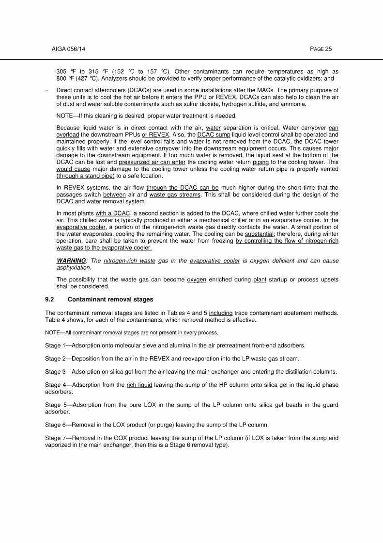
AIGA 056/14 PAGE 25
305 °F to 315 °F (152 °C to 157 °C). Other contaminants can require temperatures as high as 800 °F (427 °C). Analyzers should be provided to verify proper performance of the catalytic oxidizers; and
– Direct contact aftercoolers (DCACs) are used in some installations after the MACs. The primary purpose of these units is to cool the hot air before it enters the PPU or REVEX. DCACs can also help to clean the air of dust and water soluble contaminants such as sulfur dioxide, hydrogen sulfide, and ammonia.
NOTE—If this cleaning is desired, proper water treatment is needed.
Because liquid water is in direct contact with the air, water separation is critical. Water carryover can overload the downstream PPUs or REVEX. Also, the DCAC sump liquid level control shall be operated and maintained properly. If the level control fails and water is not removed from the DCAC, the DCAC tower quickly fills with water and extensive carryover into the downstream equipment occurs. This causes major damage to the downstream equipment. If too much water is removed, the liquid seal at the bottom of the DCAC can be lost and pressurized air can enter the cooling water return piping to the cooling tower. This would cause major damage to the cooling tower unless the cooling water return pipe is properly vented (through a stand pipe) to a safe location.
In REVEX systems, the air flow through the DCAC can be much higher during the short time that the passages switch between air and waste gas streams. This shall be considered during the design of the DCAC and water removal system.
In most plants with a DCAC, a second section is added to the DCAC, where chilled water further cools the air. This chilled water is typically produced in either a mechanical chiller or in an evaporative cooler. In the evaporative cooler, a portion of the nitrogen-rich waste gas directly contacts the water. A small portion of the water evaporates, cooling the remaining water. The cooling can be substantial; therefore, during winter operation, care shall be taken to prevent the water from freezing by controlling the flow of nitrogen-rich waste gas to the evaporative cooler.
WARNING: The nitrogen-rich waste gas in the evaporative cooler is oxygen deficient and can cause asphyxiation.
The possibility that the waste gas can become oxygen enriched during plant startup or process upsets shall be considered.
9.2 Contaminant removal stages
The contaminant removal stages are listed in Tables 4 and 5 including trace contaminant abatement methods. Table 4 shows, for each of the contaminants, which removal method is effective.
NOTE—All contaminant removal stages are not present in every process.
Stage 1—Adsorption onto molecular sieve and alumina in the air pretreatment front-end adsorbers.
Stage 2—Deposition from the air in the REVEX and reevaporation into the LP waste gas stream.
Stage 3—Adsorption on silica gel from the air leaving the main exchanger and entering the distillation columns.
Stage 4—Adsorption from the rich liquid leaving the sump of the HP column onto silica gel in the liquid phase adsorbers.
Stage 5—Adsorption from the pure LOX in the sump of the LP column onto silica gel beads in the guard adsorber.
Stage 6—Removal in the LOX product (or purge) leaving the sump of the LP column.
Stage 7—Removal in the GOX product leaving the sump of the LP column (if LOX is taken from the sump and vaporized in the main exchanger, then this is a Stage 6 removal type).
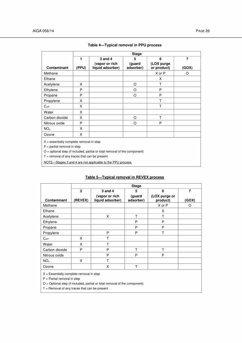
AIGA 056/14 PAGE 26
Table 4—Typical removal in PPU process
Contaminant
Stage
1 3 and 4 5 6 7
(PPU) (vapor or rich
liquid adsorber) (guard
adsorber) (LOX purge or product) (GOX)
Methane X or P O
Ethane X
Acetylene X O T
Ethylene P O P
Propane P O P
Propylene X T
C4+ X T
Water X
Carbon dioxide X O T
Nitrous oxide P O P
NOx X
Ozone X
X = essentially complete removal in step
P = partial removal in step
O = optional step (if included, partial or total removal of the component)
T = removal of any traces that can be present
NOTE—Stages 3 and 4 are not applicable to the PPU process.
Table 5—Typical removal in REVEX process
Contaminant
Stage
2 3 and 4 5 6 7
(REVEX) (vapor or rich
liquid adsorber) (guard
adsorber) (LOX purge or
product) (GOX)
Methane X or P O
Ethane X
Acetylene X T T
Ethylene P P
Propane P P
Propylene P P T
C4+ X T
Water X T
Carbon dioxide P P T T
Nitrous oxide P P P
NOx X T
Ozone X T
X = Essentially complete removal in step
P = Partial removal in step
O = Optional step (if included, partial or total removal of the component)
T = Removal of any traces that can be present
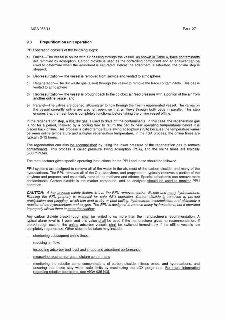
AIGA 056/14 PAGE 27
9.3 Prepurification unit operation
PPU operation consists of the following steps:
a) Online—The vessel is online with air passing through the vessel. As shown in Table 4, trace contaminants are removed by adsorption. Carbon dioxide is used as the controlling component and an analyzer can be used to determine when the adsorbent is saturated. Before the adsorbent is saturated, the online step is stopped;
b) Depressurization—The vessel is removed from service and vented to atmosphere;
c) Regeneration—The dry waste gas is sent through the vessel to remove the trace contaminants. This gas is vented to atmosphere;
d) Repressurization—The vessel is brought back to the coldbox air feed pressure with a portion of the air from another online vessel; and
e) Parallel—The valves are opened, allowing air to flow through the freshly regenerated vessel. The valves on the vessel currently online are also left open, so that air flows through both beds in parallel. This step ensures that the fresh bed is completely functional before taking the online vessel offline.
In the regeneration step, a hot, dry gas is used to drive off the contaminants. In this case, the regeneration gas is hot for a period, followed by a cooling flow to return the bed to near operating temperatures before it is placed back online. This process is called temperature swing adsorption (TSA) because the temperature varies between online temperature and a higher regeneration temperature. In the TSA process, the online times are typically 2-12 hours.
The regeneration can also be accomplished by using the lower pressure of the regeneration gas to remove contaminants. This process is called pressure swing adsorption (PSA), and the online times are typically 5-30 minutes.
The manufacturer gives specific operating instructions for the PPU and these should be followed.
PPU systems are designed to remove all of the water in the air, most of the carbon dioxide, and many of the hydrocarbons. The PPU removes all of the C4+, acetylene, and propylene. It typically removes a portion of the ethylene and propane, and essentially none of the methane and ethane. Special adsorbents can remove more contaminants. Carbon dioxide is the marker compound, and an analyzer should be used to monitor PPU operation.
CAUTION: A key process safety feature is that the PPU removes carbon dioxide and many hydrocarbons. Running the PPU properly is essential for safe ASU operation. Carbon dioxide is removed to prevent precipitation and plugging, which can lead to dry or pool boiling, hydrocarbon accumulation, and ultimately a reaction of the hydrocarbons and oxygen. The PPU is designed to remove many hydrocarbons, but if operated improperly allows them to enter the coldbox.
Any carbon dioxide breakthrough shall be limited to no more than the manufacturer’s recommendation. A typical alarm level is 1 ppm, and this value shall be used if the manufacturer gives no recommendation. If breakthrough occurs, the online adsorber vessels shall be switched immediately if the offline vessels are completely regenerated. Other steps to be taken may include:
– shortening subsequent online times;
– reducing air flow;
– inspecting adsorber bed level and shape and adsorbent performance;
– measuring regenerator gas moisture content; and
– monitoring the reboiler sump concentrations of carbon dioxide, nitrous oxide, and hydrocarbons, and ensuring that these stay within safe limits by maximizing the LOX purge rate. For more information regarding reboiler operations, see AIGA 035 [43].
AIGA 056/14 PAGE 28
The plant shall be shut down if any of the following occurs:
– the carbon dioxide leaving the PPU exceeds 10 ppm;
– the reboiler sump contaminant concentrations exceed safe limits, see AIGA 035 [43]; or
– the adsorber vessel cannot be switched within 30 minutes after the high carbon dioxide alarm and there is no reboiler sump analysis.
A low but continuous slip of carbon dioxide is just as dangerous as a breakthrough at the end of the cycle because it indicates that air contaminants such as acetylene, other hydrocarbons, and moisture are not being adsorbed. If the level of a continuous slip reaches 0.2 ppm to 0.5 ppm of carbon dioxide (according to the detection capability of the analyzer), investigate the cause of the increased carbon dioxide slip and seek technical assistance to determine whether the plant can continue to safely operate.
For a PPU to work effectively, each regeneration step shall be complete and correct. This ensures that the adsorbent has the full capacity for the next online step.
The key variable for each type of process shall be monitored and maintained. For a TSA, the adsorbent is regenerated with heat, so required heat must be introduced into the vessel. The correct temperature shall be reached at the outlet of the regenerated vessel, the regeneration flow rate shall be adequate, and the heating time shall be long enough.
The cooling step shall also be sufficient to completely cool the regenerated adsorber vessel before placing it back online. If the cooling step is insufficient, the adsorbent capacity is reduced; in addition, hot gas is sent to the downstream equipment potentially causing damage. There should be a high temperature alarm and shutdown for the air leaving a TSA PPU to prevent damage to the downstream filter and cryogenic equipment.
In all cases, the regenerating gas shall be dry. If a potential source of water into the regeneration gas exists, a dew point analyzer should be used. The most common source of water into regeneration gas is when a steam heater is used and the steam heater develops a leak. If the dew point analyzer alarms, the source of the water should be quickly investigated and resolved or the adsorbent will be permanently damaged.
Reactivation heat is usually obtained through gas-fired, steam, or electric heaters. Each system should have temperature and/or low-flow shutdown protection to preserve the integrity of the heater and the rest of the system, especially in case of loss of reactivation gas flow.
For a PSA, the key variables are flow and pressure of the regeneration gas. These should be monitored to ensure proper regeneration. A low regeneration flow alarm should be present to alert the operator to possible insufficient regeneration.
PSA can cause more pressure fluctuations in the inlet air to the coldbox. For stable coldbox operation, the repressurization rate shall be controlled.
During regeneration, the adsorber vessel is at low pressure. It is important to bring the adsorber vessel close to inlet air pressure before opening the feed valves to return the vessel to service. If the inlet or outlet valve is opened before the vessel is at or close to the feed pressure, significant and permanent damage can occur due to rapid repressurization flow. Pressure interlocks shall be used to prevent the valves from being opened at the incorrect time.
The water content of the inlet air shall be kept below its design maximum or premature carbon dioxide breakthrough occurs when the excess water displaces the carbon dioxide. The most common source of extra water is a high PPU inlet air temperature.
NOTE—Even a small increase in the inlet air temperature indicate significant excess water because the water content of the
air approximately doubles for every 18 °F (10 °C) increase in its temperature.
It is also important to ensure that no liquid water is carried over from upstream equipment into the PPU. This liquid water overloads the adsorbent, displacing carbon dioxide and causing premature breakthrough. In
AIGA 056/14 PAGE 29
addition, the liquid water can damage the adsorbents and cause temperatures in excess of 212 °F (100 °C) within the bed.
The adsorbents are granular materials, typically 1 mm to 5 mm in size. These materials are prone to breakdown or dusting if the PPU is incorrectly operated. In addition, a small amount of dust is present in the adsorbent during initial loading of the material. A filter or equivalent safeguard is required to prevent this dust from entering the cryogenic equipment. Filters can be either internal or external to the adsorber vessel. Internal filters are self cleaning, but might require occasional inspection. External filters might require occasional inspection and replacement.
The adsorbents are powerful desiccants and shall be handled carefully during loading and unloading. They adsorb water readily and can get hot, reaching over 212 °F (100 °C). The manufacturer’s instructions and SDSs should be consulted before undertaking these operations.
In some cases the regeneration gas is enriched in oxygen, either during normal operation, startup, or process upsets. This possibility shall be taken into account during design. The materials of construction of the PPU, the adsorbent materials, and the PPU cleaning method shall be suitable for the maximum oxygen concentration that can be encountered. It should be noted that the regeneration heaters can be an ignition source.
Molecular sieve adsorbents adsorb nitrogen preferentially to oxygen. When the vessels are depressurized, the gas in the void spaces is vented and replaced by nitrogen-enriched gas released from the adsorbent.
WARNING: At any time, molecular sieve vessels can contain oxygen-deficient atmospheres that can asphyxiate anyone entering the vessel or working near an opening of the vessel. Anyone working in the vessel shall follow confined space entry procedures.
9.4 REVEX operation
In REVEXs, the air leaves the MAC, is cooled close to ambient temperature, and then enters the main heat exchanger where it is further cooled to cryogenic temperatures. As it is cooled, water, carbon dioxide, and some hydrocarbons (see Table 5) freeze out on the surface of the heat exchanger. The low boiling point hydrocarbons, trace levels of carbon dioxide, and nitrous oxide in the air exit the main heat exchanger and enter the cryogenic distillation section of the plant. These trace contaminants shall be dealt with either by exiting the system in various oxygen product streams (either gaseous or liquid) or by removal through cryogenic adsorption.
The air is cooled by warming cold gas streams of oxygen, nitrogen, and waste gas. After several minutes, switching valves direct the air stream into the passages that formerly contained the waste gas, and the waste gas is directed into the former air passages. As the waste gas warms up in the BAHX, it evaporates and sweeps the contaminants that were deposited on the heat exchanger surface, cleaning up the passage.
A careful balance shall be maintained in the heat exchanger to ensure that the deposited contaminants are removed. The waste gas has a greater capacity to carry away the trace contaminants because it is at a lower pressure; however, it is a few degrees colder than the air stream, which reduces its capacity to remove the trace contaminants. The physical properties of the air and waste gas are such that without some extra measures, the waste gas is too cold at the cold end of the heat exchanger to remove the trace contaminants. Over time, the cold end of the exchanger is not completely cleaned and eventually plugs up.
To assist in the cleanup, more cold gas is needed at the cold end of the heat exchanger. The most common method is to take a portion of nitrogen from the top of the HP column and warm it up in the main heat exchanger. This warmer HP gas is then expanded. When the gas is expanded, it is cold enough to be added to the waste gas stream at the cold end of the main heat exchanger, providing additional cold gas. This stream is called the reheat (or unbalance) stream, and its control is essential for complete REVEX cleanup.
While nitrogen from the HP column is the most common source of this reheat stream, other streams can also be used depending on the process.
Temperatures at the REVEX midpoint should be monitored. If they are too cold there is too much reheat flow, which reduces the carbon dioxide cleanup capacity and increases the warm-end differential temperature (∆T).
AIGA 056/14 PAGE 30
(Increasing the warm-end ∆T increases the refrigeration requirements of the process and is inefficient.) If the
reheat flow is too low then the midpoint temperatures are too warm and the cold end ∆T of the heat exchanger becomes too large, resulting in inadequate carbon dioxide cleanup. While the exact range of acceptable midpoint temperatures depends on the particular process and should be obtained from the manufacturer,
typical midpoint temperatures range from –94 °F to –184 °F (–70 °C to –120 °C).
Most plants have two or more main heat exchangers in parallel. Each main exchanger shall have an individual midpoint temperature measurement. It is critical for carbon dioxide cleanup that every midpoint temperature be controlled within the acceptable range. Each main heat exchanger shall have a balancing valve on a nonreversing stream (typically oxygen) to correct for flow variations caused by differences in individual piping and exchanger flow resistances. This valve can be adjusted to force more or less flow to each exchanger, bringing the individual midpoint temperatures within acceptable limits. These valves are typically set during the initial plant commissioning and are rarely readjusted.
The cold-end temperature shall be kept above the liquefaction temperature of air. When the exchanger is switched the liquid inventory is lost if air liquefies in the main exchanger. This refrigeration loss is unacceptable and equipment damage can also occur.
The cold-end temperature shall be kept below the maximum allowable temperature (provided by the manufacturer) to ensure that hydrocarbons are contained within the REVEX and not carried into the air separation column in high concentrations. If at any time the cold-end temperature rises above the maximum allowable temperature, the airflow through that vessel to the air separation column shall be stopped immediately. Restart only when safe temperatures are attained.
If the exchanger is not cleaning up properly, deposited carbon dioxide remains in the REVEX. This impacts plant performance by reducing the heat transfer and increasing the warm-end temperature difference, thereby increasing the refrigeration load. The increased warm end ∆T is typically the first indication of a cleanup problem. If inadequate cleanup continues long enough the air and waste pressure drops also increase, but this is typically long after the warm end ∆T becomes unacceptable.
The typical onstream time for a heat exchanger is 4-10 minutes. Reducing the onstream time increases the cleanup capacity of the system but requires more refrigeration and increases switch loss.
When the plant is shut down, water shall be drained from the REVEX. If this is not done, the water can freeze and block or damage the exchanger. A proper warm purge is needed to prevent the warm end of the exchanger from becoming too cold. If the warm end of the exchanger gets below 32 °F (0 °C), special procedures defined by the manufacturer should be used before operating the plant again.
The air and waste flows on the warm end of the heat exchanger are directed to the proper passages by switch valves. The cold end of the exchanger typically has check valves. These switching and check valves shall be properly maintained to ensure reliable operation.
Water condenses in the main exchanger as the air cools. Any corrosive gases in the air dissolves in this water and can be very corrosive to the main exchanger. If high levels of acid gases are present, the air should be pretreated to prevent these components from entering the main exchanger. The aluminum in the BAHX is particularly susceptible to corrosion from chlorine and SOx.
REVEXs experience pressure and temperature cycles every few minutes. Over many years of operation, these can cause fatigue failure of the exchangers and the passages begin to leak. The product streams should be routinely monitored for leaks and repairs made to the exchanger as needed. These repairs are specialized and should be made only by qualified personnel.
Some trace contaminants get through the main REVEX because of their relatively low boiling temperature. Of most concern is acetylene, which does not freeze out in the REVEX. Acetylene is only slightly soluble in liquid cryogens and any solid crystals that form can explosively decompose. Carbon dioxide also leaves the main exchanger in low ppm quantities and can precipitate in downstream equipment creating locations where dry boiling can occur. These two components are removed by cryogenic adsorption (see 12.2) and purge from the sump of the LP column. A minimum purge rate is specified in AIGA 035 [43].
AIGA 056/14 PAGE 31
Because the feed to the REVEX contains plugging contaminants, the startup takes a great deal of care. The manufacturer gives specific instructions. However, the typical basic procedure is as follows:
a) Send a portion of the air to a heater and then send this warm air (110 °F to 150 °F [43 °C to 66 °C]) throughout the cryogenic equipment to evaporate any liquid water in the plant;
b) Isolate the distillation column(s);
c) Send air through the main exchanger, let down the pressure, and return the air to the waste passages. Switch the exchangers on a relatively short time cycle. Send a portion of the air to the expander to provide refrigeration to cool down the exchangers. The expander exhaust should be sent to the waste circuit to maximize the cleanup flow;
d) Cool down the main exchangers evenly to prevent carbon dioxide accumulation and blockage;
e) When the cold end of the main exchanger is approximately −100 °F (–73 °C), the air is essentially water-free. This dry air is then used to blow out the cryogenic portion of the plant to ensure there is no vapor water in the system; and
f) After blowing out the cryogenic system, cool to liquid air temperatures and then establish normal flows.
Some higher boiling point components do not completely clean up in the REVEX, even when the midpoint temperatures are properly maintained. These components shall be removed by periodic deriming. When this derime occurs, all of these components are released over a few hours. In particular, NOx components can be released in relatively high concentrations. Personnel should take care to keep their exposure to within safe limits during these periods. When the atmosphere contains NOx and conjugated dienes, these components can react to form a gum that remains in the REVEX. This gum shall be removed by periodic deriming. If allowed to accumulate to sufficient levels, it can spontaneously explode [45, 46, 47].
When a REVEX is shut down, proper procedures shall be used to ensure that the restart is trouble-free and safe. The exchanger should be completely blocked in to prevent cold gas from flowing through it.
If the warm end of the exchanger is too cold, water freezes and damages the exchanger. The exchanger’s warm-end temperature shall be above the manufacturer’s minimum for restart. Procedures should be established to warm the exchangers before placing them in switching service if the warm-end temperatures are below the manufacturer’s minimums.
9.5 Supplemental mechanical chillers
Sometimes a mechanical chiller is used to condense moisture from the compressed air to reduce water loading on the PPU or REVEX, improve the PPU adsorbent capacity, and improve process operating efficiency. Cooling is obtained by the evaporation of a refrigerant in a chiller. Chillers should have low temperature controls to prevent freezing water in the process stream handled by the chiller.
The possibility of leakage of the refrigerant system shall be considered. Depending on the pressures, air can leak into the refrigerant system, potentially creating an explosive mixture. Alternatively, the refrigerant can leak into the process, again creating an explosive mixture. The refrigerant can then also pass into the downstream equipment, and its effect on the process and equipment shall be considered.
The possibility and hazards of leaks shall consider scenarios of normal operation, startup, and shutdown.
When maintenance or repair of this equipment involves opening the system or possible exposure to the refrigerant, consideration shall be given to the toxic or flammable properties of the refrigerant used. The Montreal Protocol on Substances that Deplete the Ozone Layer and government regulations restrict the use of many fluorocarbons and prohibit their release to the atmosphere [61]. Special equipment and procedures are necessary to contain these refrigerants during maintenance. Any refrigerant leaks to the atmosphere should be promptly repaired.
AIGA 056/14 PAGE 32
9.6 Caustic scrubbers
Caustic scrubbers are occasionally used to remove carbon dioxide from the air. The most significant hazard associated with these scrubbers is handling of caustic soda solution. Serious burns can be caused by exposure to the caustic solution. The manufacturer’s recommendations on safe handling of the caustic solution shall be followed. Protective rubber clothing and face shields shall be worn any time work is performed around the caustic system.
Guards shall be installed around couplings and shafts adjacent to pump seals to prevent the slinging of leaking caustic solution into surrounding areas and onto personnel.
In many applications, caustic scrubbers are followed by driers to remove the remaining water from air. It should be noted that driers are not designed to provide removal of carbon dioxide and other contaminants but to remove water only. Any systems designed to prevent caustic entrainment into the drier shall be maintained in accordance with the manufacturer’s instructions.
10 Expanders
Expanders are used to provide refrigeration to the process. There are two types of expanders, turbo and reciprocating.
Expanders extract energy from the process stream by loading electrical, mechanical, or hydraulic devices attached to the expander. Turboexpanders are usually loaded by generators, blowers, booster compressors, or oil dynamometers. Reciprocating expansion engines are usually loaded by being directly coupled to compressors or belt loaded by electric generators.
When operating expanders, the following should be taken into consideration:
– loss of loading and overspeed;
– oil contamination of the process;
– abnormally low temperatures;
– solids in the gas stream;
– loss of lubrication;
– abnormal bearing temperature;
– abnormal vibration;
– abnormal speed;
– critical speed;
– fouling of the expander with ice or carbon dioxide; and
– startup and shutdown.
Maintenance schedules can be arranged on an operating hours or calendar basis as most suitable for the specific equipment.
10.1 Loss of loading and overspeed
If for any reason the loading device fails to continue to apply load to the expander shaft, the work created by the expanding gas causes the expander to rapidly increase its speed to a point where mechanical damage can occur.
AIGA 056/14 PAGE 33
Expanders shall be equipped with an overspeed shutdown control system that stops the machine when loss of load occurs. Generator-loaded expanders also shall be equipped with instrumentation to sense a separation from the power grid and shut down the machine before damage can occur.
10.2 Oil contamination of the process
10.2.1 Turboexpanders
Turboexpanders have a labyrinth gas sealing system to prevent the escape of extremely cold process gas to the atmosphere or bearings and to prevent oil contamination of the process. Improper relative fluid pressures in the cavities of the seal system or loss of seal gas pressure causes the escape of cold process gas or oil migration along the shaft and into the process gas stream. Depending on the design of the turboexpander, the seal gas can be supplied from either the process gas or an external source. An external source of seal gas should be provided when the expander is shut down to prevent the migration of cold and/or oxygen-rich gas into the oil-lubricated section of the expander.
Seal gas shall be dry, oil-free, and filtered to prevent system contamination and expander damage.
Seal gas pressure measurement shall be included in the expander’s control system. The seal gas pressure shall be maintained above the manufacturer’s minimum recommendation to allow starting and operating of the expander. If the seal gas pressure falls below the minimum recommendation, the expander and the lube oil pump shall be shut down immediately. If the seal gas pressure falls below the minimum value when the expander is shut down, the control system shall shut down the lubrication pump.
If oil appears in the seal gas vent, there is significant increase in lube oil consumption, or there is any reason to suspect oil contamination, the expander should be shut down and either repaired or replaced with a spare cartridge. Process piping connected to the expander should be inspected for any oil contamination and cleaned if required.
10.2.2 Reciprocating expanders
There are two classes of reciprocating expanders, nonlubricated and lubricated.
10.2.2.1 Nonlubricated reciprocating expanders
Nonlubricated machines are designed with extra-length, open distance pieces and piston rods fitted with slinger collars to prevent oil migration from the lubricated section of the expander. The open distance piece should be inspected frequently to ensure there is no accumulation of oil in this area.
10.2.2.2 Lubricated reciprocating expanders
Although oil-lubricated expansion engines are designed with oil cleanup systems, excessive oil can cause overloading of the cleanup system and ultimately contamination of the plant.
Oil feed rate to the cylinder bore should be kept to a minimum, compatible with good ring life and cylinder condition.
The amount of oil passing through the cylinder of a lubricated expansion engine is not limited to that introduced through the cylinder lubricator. Crankcase oil, sometimes in quantities far in excess of this lubricator flow, can be introduced at the crank end of the cylinder. This condition is usually caused by some malfunction of the piston rod oil wipers or failure to drain accumulated oil from the distance pieces.
In the case of lubricated expansion engines, close attention shall be paid to the oil removal equipment. Oil removal equipment is usually of the packed-bed or mechanical-filter type. The oil removal equipment is operated either for a fixed period or until a given pressure drop across the system occurs. At such time the system is removed from service and usually regenerated using a flow of hot (preferably inert) gas. It is essential that the volume of regeneration flow and its ultimate effluent temperature be maintained at the level specified by the manufacturer.
AIGA 056/14 PAGE 34
Following such regeneration, the system should be cooled down to the temperature prescribed by operating instructions before being placed back in service. This is especially important if the process stream contains sufficient oxygen to support combustion.
Some of the mechanical filtration systems are regenerated by removing the filter media from the filter and washing it in a solvent. The washed media is dried and reinstalled in the filter. Care shall be taken to ensure complete washing and drying and to ensure that the media is properly reinstalled to prevent filter bypassing.
The piping immediately downstream from either a packed bed or a mechanical filter should be inspected frequently during initial periods of operation to ascertain that filter bypassing or breakthrough is not occurring.
Packed beds should be replaced at least as frequently as recommended by the manufacturer unless sufficient operating history exists to allow extending the bed life.
10.3 Abnormally low temperatures
The operation of expanders below the dew point temperature of the gas being expanded forms liquid in the expander. The presence of liquid in a reciprocating expansion engine cylinder causes major damage. In turboexpanders not designed for partial liquefaction, the presence of liquid droplets can cause nozzle erosion or impeller erosion, both of which can cause a loss of efficiency, unbalance, and eventual mechanical failure. Turboexpanders designed to tolerate the presence of liquid in their exhaust can be operated without the risk of erosion damage.
To determine the state of the fluid at the expander discharge, the design operating conditions of the expander should be checked against the physical properties (Temperature-Entropy Chart) of the gas being expanded.
To prevent the formation of liquid in expanders not designed for such service, the discharge temperature of the expander should be maintained no colder than 5 °F to 15 °F (2.8 °C to 8.3 °C) above the dew point of the gas being expanded.
Expanders not designed to handle liquid formation should have a temperature monitoring device in the expander discharge that provides an alarm in the event of low temperature.
The expander inlet temperature should be maintained in accordance with the manufacturer’s recommendation. In an extreme case, a very cold inlet temperature can cause liquid to generate over a turboexpander’s inlet nozzles.
10.4 Solids in gas stream
When present in the expander inlet gas stream, particles of pipe scale or desiccant fines can cause serious erosion damage to the machine’s internal parts. Turboexpanders are especially susceptible to nozzle, impeller, and labyrinth gas seal wear. Reciprocating expansion engines experience accelerated ring and liner wear.
Inlet screens should be used to minimize the amount of solid particles entering the expander. These screens are ordinarily made of finely woven mesh. The pressure drop across the inlet screen should be monitored, and may be equipped with an alarm to determine when cleaning or replacement is necessary and to ensure that excessive pressure drop, which could cause rupture, does not occur. The screen should be constructed so that its collapse pressure rating is greater than the expected operating pressure of the expander.
10.5 Loss of lubrication
Loss of expander lubrication quickly results in extensive machine damage. Turboexpander bearings are force-fed lubricated by either directly coupled oil pumps or electrically driven pumps. Reciprocating expander bearings are splash lubricated from the crankcase or force lubricated by pumps either directly driven from the crankshaft or remotely driven.
When direct-coupled oil pumps are used for lubrication, an auxiliary electric-driven pump or accumulator reservoir is also necessary. The system oil pressure shall be monitored with a pressure sensor that can start the auxiliary oil pump when oil pressure falls and shut down the expander if the pressure falls further. When
AIGA 056/14 PAGE 35
electrically driven oil pumps are used for lubrication, an accumulator reservoir is necessary to provide lubrication during an expander coastdown after loss of electric power. When accumulator reservoirs are used, they should be automatically activated.
The accumulator pressure should be checked during scheduled maintenance of the expander.
10.6 Abnormal bearing temperature
Abnormally high or low bearing temperatures can be experienced in the operation of expanders. Abnormally high bearing temperatures can occur if oil flows to the bearing are restricted, abnormal loading is applied to the bearing or the bearing is damaged. Abnormally low bearing temperatures are most particular to turboexpanders and can occur in the event of heavy seal leakage or if oil flows are restricted. Turboexpanders and most reciprocating expanders have temperature-measuring instrumentation. This instrumentation should also provide alarm and shutdown functions. Operating personnel should watch for significant deviations from normal operating temperatures and investigate their causes. Low cold-end bearing temperature detection is often part of the permissive start circuitry on a turboexpander.
10.7 Abnormal vibration
Significant damage can occur to a turboexpander whenever there is excessive vibration. Proximity-type vibration probes and monitors shall be installed on all turboexpanders to measure shaft movement and should actuate alarms, shutdown systems, or both. The data from these sensors should be periodically analyzed. If the readings are abnormal or if the turboexpander shuts down on high vibration, careful review of the data by experts can provide insights into the cause of the high vibration readings. The turboexpander shall not be restarted until the cause of the excessive vibration reading is resolved.
A reciprocating expander typically has a seismic switch.
10.8 Abnormal speed
Abnormal speed is either operating in excess of the design limit or at a level which does not produce the required refrigeration. Turboexpanders are susceptible to damage if operated in excess of the design limits. It is a good design practice to incorporate an excessive speed limit into the expander control system. Turboexpanders should be equipped with alarms and shutdown controls to protect against operation in excess of the design limits.
10.9 Critical speed
Turboexpanders are susceptible to damage if operated near a critical resonance frequency. These critical speeds, based on resonance frequencies (no-dwell zones) are defined by the manufacturer. During startup, it is necessary to pass quickly through any critical resonance frequencies while loading the turboexpander. It is a good design practice to incorporate speed limits into the expander control system. If the manufacturer defines a no-dwell zone, an appropriate shutdown should be installed.
10.10 Fouling of expander with ice or carbon dioxide
Expander performance can be adversely affected by the formation of water ice or carbon dioxide deposits either on the inlet screen or within the expander itself. Typical sources of these contaminants are:
– prepurifier breakthrough;
– water leakage from compressor coolers;
– REVEX upset;
– atmospheric air aspiration during a shutdown; and
– improper deriming.
AIGA 056/14 PAGE 36
Fouling of the expander can occur immediately following one of these events or when accumulated contaminants migrate from elsewhere within the coldbox when operating conditions change.
Operators should monitor the expander performance as well as the differential pressure across the expander inlet screen. Deterioration of the performance or high differential pressure can indicate expander fouling. The need for frequent deriming of the expander can indicate an ongoing fouling problem.
10.11 Startup and shutdown
The equipment manufacturer’s recommended starting procedure to apply the load should be followed. Special care should be exercised in loading the expander. A turboexpander can require that the load be applied quickly to avoid operating at low or critical speeds that could damage the expander.
Shutdowns shall be designed to stop the gas flow to the expander by closing the expander inlet valve. It is also a good practice to close the turboexpander inlet nozzles or move the reciprocating expansion engine cam to the no-flow position. For generator-loaded expanders, the control system shall be designed to prevent the disengagement of the generator before the gas flow has been stopped. Failure to do so can cause damage to the expander machine. A complete functionality test of the expander safety control system should always be performed during normally scheduled maintenance of the expander.
Due to its design, the generator-loaded expander can operate as a compressor if the generator acts as a motor. This can lead to overheating and severe mechanical damage. The control safety system should be designed to prevent the expander generator from operating as a motor by incorporating special electrical sensing devices. Although some early expander control system designs allowed starting the expander by first motorizing the generator, this is not the current design practice.
10.12 Operating and maintenance procedures
Written procedures shall be used to start, operate, and shut down each expander and its loading device. The key operating parameters shall be monitored periodically. Abnormal conditions and trends shall be investigated and resolved.
A preventive maintenance schedule should be prepared for each expander and its loading device. Frequencies should be based initially on vendor recommendations and eventually on historical data.
Maintenance on reciprocating expansion engines is typically performed annually.
11 Cryogenic pumps
This section briefly reviews a number of design and operational factors that affect the operation and maintenance of cryogenic pumps. Additional information on the design and operation of cryogenic pumps can be found in AIGA 055, Installation Guide for Stationary, Electric-Motor-Driven, Centrifugal Liquid Oxygen Pumps and EIGA Doc 159, Reciprocating Cryogenic Pumps and Pump Installations [62, 63].
11.1 General
The functional design and operation of an air separation plant can depend on the application of one or more cryogenic liquid pumps. The type of pump used can vary depending on the requirements of the process or the end user. These pumps can be required to:
– transfer process liquids from one distillation column to another;
– circulate LOX through a reboiler;
– circulate process liquids through an adsorber;
– pump liquid products between the process and storage tanks;
– pump liquid products to a higher pressure for vaporization in the ASU main heat exchanger;
AIGA 056/14 PAGE 37
– pump liquid products from LP storage into HP storage tanks and/or back-up vaporizers; and
– pump liquid products between storage tanks and trailers or railcars.
The plant designer shall determine the oxygen content of the pumped fluid during all modes of operation. If any operating mode results in oxygen-enriched fluid, pumps that are suitable for oxygen service shall be used.
11.2 Types of pumps
11.2.1 Centrifugal
A centrifugal pump can be designed to meet a wide range of flow and head generating requirements. These pumps can be mounted either horizontally or vertically. Impeller size, shaft rotating speed, and the number of pump stages determine the achievable flow and pressures. Specific design rules for oxygen pumps are addressed in AIGA 055 [62].
11.2.2 Reciprocating
A reciprocating pump is a low volume flow/high head generating device. The inlet piping and cylinder jacket are often vacuum-insulated to minimize heat leak and prevent inlet liquid vaporization. Pulsation dampeners can minimize fluid hammer effects caused by the high reciprocating speed of the piston. See EIGA Doc 159 for additional information on reciprocating pumps [63].
A reciprocating pump may be used continuously within the ASU to remove a liquid product, typically oxygen, and pump it to a very high pressure before it is vaporized in the main heat exchanger. A reciprocating pump may also be used intermittently to remove a liquid product from storage and pump it to a very high pressure before it is vaporized in a heat exchanger. The vaporized product can be used to fill HP gas cylinders or gas receivers.
Due to the inherent ability of reciprocating pumps to generate very high discharge pressures:
– Pressure relief devices (PRDs) shall be provided to protect personnel and equipment from overpressure and dead-ended flow conditions;
– The pump instrumentation and electrical controls shall include an automatic HP and a low motor electrical load shutdown; and
– HP discharge gauges should be equipped with snubbers, plastic lenses, and blow-out ports.
11.3 Materials of construction
All cryogenic pumps shall be constructed with materials suitable for the intended process conditions to ensure safe and reliable service. The oxygen content of the fluid handled can vary in purity from very high to insignificant depending on process conditions. The fluid purities over the entire operating range including normal operation, startup, shutdown, and process upsets shall be considered when determining whether a pump is designed for oxygen service.
11.4 Pump system design
When designing and installing a cryogenic pump, care shall be taken to ensure that piping stresses due to pipe cooldown shrinkage, liquid weight, ice formation, and pump operating dynamic forces are isolated from the pump housing to prevent damage. This can be accomplished by designing flexibility into the pump’s suction and discharge piping system and by providing proper support for these lines. The preferred design method of isolation is to use flexible connections such as braided flexible hoses at pump tie-in points to the piping system.
A pump inlet screen shall be installed in the suction line to prevent particles from damaging the pump. The recommended inlet screen mesh size shall be determined by the pump manufacturer, see AIGA 055 [62]. It is preferable to install the inlet screen between the pump and the flexible connection.
AIGA 056/14 PAGE 38
The piping system for cryogenic pumps shall be designed to be leak free by minimizing the use of threaded and flanged connections. Leaking cryogenic fluids can crack carbon steel enclosures, mounting frames, and motor housings and can also freeze motor bearings.
CAUTION: Oxygen leaks around pump drive motors can cause an extremely hazardous condition resulting in a fire or explosion. Stainless steel plate, structural members, or shields should be used to protect personnel and equipment from liquid leaks. The piping layout and pump location should be such that if a leak develops the liquid from the leak drains away from any equipment, the pump foundation, or any other area that is endangered by the cold fluid or by a high oxygen content atmosphere.
A PRD shall be installed on the pump suction line to protect the pump housing and seal from overpressure in the event of a trapped liquid condition. The set pressure of this relief device shall be below the maximum allowable working pressure of the pump housing and seal.
The location and arrangement of the pump and its piping shall be considered for pump cooldown and priming and to minimize loss of product. The pump suction piping from the liquid reservoir should be as short as possible with a minimum of bends and fittings. Adequate net positive suction head (NPSH) should be available at all liquid reservoir levels to avoid pump cavitation. A pump cooldown and recirculation line, equipped with an appropriate control valve, should return cold gas and excess pumped liquid back to the liquid reservoir when the pump is cooling down or operating. The recirculation function can be automated with pressure control instrumentation. Any vented liquid should be discharged to a safe location (see 17.2). Valves should be provided to isolate the pump from the liquid supply when not in use or in the event of an emergency. A discharge check valve should also be provided.
A pump mechanical shaft seal area shall be purged with an inert dry gas to limit ice formation around the seal.
Proper insulation of a cryogenic pump suction pipe is essential to minimize heat leak into the suction liquid, ensuring ease of pump priming and good pump operation. The suction piping heat leak shall be included in the pump NPSH calculation. The insulation system used may include a metal piping duct and pump box or individual piping component insulation (either closed-cell insulation or vacuum jacketed) and should be sealed against moisture infiltration. If the metal duct and pump box insulation design is used, it shall be purged with an inert gas. Typically, if the pump box design is used, all required suction and discharge isolation valves, inlet strainers, flexible connections, and check valves are located within the pump box.
Depending on process design requirements, the discharge piping from a pump including the pump cooldown and recirculation line might not be insulated.
11.5 Special considerations for oxygen service
There are special considerations for safe design and operation of an oxygen pump. These include:
– materials of construction;
– isolation and drain valve location and controls;
– seal leak detection;
– oxygen compatibility of lubricants; and
– purge of motors and seals.
Details of considerations for oxygen service are given in AIGA 055 [62].
11.6 Pump motor
The pump motor should be properly sized to handle any anticipated loads required of the pump. It is possible for a centrifugal pump to exceed the motor’s rated power output under low discharge pressure conditions and it should be provided with motor overload protection. Vertical and horizontal centrifugal pumps driven by direct-coupled extension of the motor shaft shall have positive means to fix the axial position of the motor shaft. This is usually accomplished by a thrust bearing.
AIGA 056/14 PAGE 39
There should be an adequate thermal barrier, by means of either a distance piece or insulating material, between the pump and the motor drive end bearing housing to protect the bearing from extreme low temperatures. Where the motor shaft is directly connected to the pump and the pump is shut down at cryogenic temperatures for extended periods, a motor drive end bearing electrical heater should be provided. Such a motor may also be equipped with a motor space heater.
Motors should be of the totally enclosed, fan-cooled type.
Motor bearing lubrication for liquid nitrogen or liquid argon pump motors should be low temperature-rated, mineral oil-based greases and oils, if the motor design isolates the lubricated components from the pump. Special care should be taken to ensure that no motor bearing lubricant could enter the process piping.
11.7 Pump operation
Avoid starting a pump until it has reached the intended operating temperature to ensure that pump prime is maintained and to prevent equipment damage. Loss of pump prime can be caused by insufficient liquid subcooling, insufficient liquid reservoir level, or high inlet screen pressure drop. A centrifugal pump can also lose prime if the discharge pressure becomes too high or too low.
The following items are recommended operating practices for cryogenic pumps:
– Pumps in liquid oxygen or oxygen-enriched service shall be shut down immediately if there is any evidence of malfunctioning such as excessive seal leakage, internal rubbing, or unusual noise;
– Pumps in inert liquid service should be shut down immediately if there is any evidence of malfunctioning such as excessive seal leakage, internal rubbing, or unusual noise;
– An oxygen pump in cold standby should be periodically drained and purged with fresh liquid to prevent the accumulation of hydrocarbons in the pump liquid over time;
– A pump equipped with external bearings should not remain shut down and flooded with liquid unless means have been provided to prevent excessive cooling of pump external bearings; and
– A manually operated pump shall be monitored locally while it is running so that corrective action can be taken as required.
Tanker loading pumps can be automatic or manual. See AIGA 086, Liquid Oxygen, Nitrogen, and Argon Cryogenic Tanker Loading System Guide, for additional information [18].
Protection against pump loss of flow or cavitation may be provided by monitoring for low motor electrical load, low pump discharge pressure, low differential pressure across the pump, or low NPSH. An NPSH device also may be provided to prevent starting of a pump without sufficient pump cool down or required inlet head. For oxygen pumps, the protection shall be in accordance with AIGA 055 [62].
11.8 Operating and maintenance procedures
Written procedures shall be used to start, operate, and shut down each pump unit. The key operating parameters shall be monitored periodically. Abnormal conditions and trends shall be investigated and resolved.
A preventive maintenance schedule should be prepared for each pump unit. Frequencies should be based initially on vendor recommendations and eventually on historical data.
Free pump shaft rotation shall be ascertained after pump maintenance.
12 Coldbox
AIGA 079, Safe Design and Operation of Cryogenic Enclosures, reviews the safe design and operation of the coldbox contains [64].
AIGA 056/14 PAGE 40
Additional information on the design and operation of specific coldbox equipment can be found in AIGA 057, AIGA 035, and AIGA 076 [2, 43, 21].
12.1 Removing particulate material
Mechanical filtering devices can be required to prevent the migration of materials through the process system. They are usually located at the source of the migrating material and at the inlet of equipment that would be sensitive to its presence. Examples are:
– Inlet and outlet screens—should be provided to retain the absorbent in the vessels;
– Screens—should be provided at pump or expander and compressor suctions; and
– Screens—may be provided when boiling oxygen to dryness, see AIGA 057 [2].
Because of their specific purpose to retain or to accumulate migrating material, these devices should be inspected and cleaned on a periodic basis.
Incidents have occurred when particulates (for example, perlite, silica gel) have entered the LP column sump and blocked reboiler passages. The incidents led to pool boiling and a dangerous accumulation of hydrocarbons. If evidence indicates that particulates have entered the LP column sump, this shall be evaluated and actions, such as a plant shutdown and particulates removal, should be considered.
12.2 Cryogenic adsorbers
Cryogenic adsorbers may be placed at various points in the process to remove hydrocarbons and carbon dioxide.
In REVEX-equipped plants, cryogenic adsorbers shall be provided to remove hydrocarbons and traces of carbon dioxide from the air that pass through the REVEX and enter the cryogenic distillation columns. Cryogenic adsorbers may be provided on PPU-equipped plants to remove contaminants that can break through the PPU.
Although cryogenic adsorbers are not typically designed to adsorb nitrous oxide, industry experience indicates that most are effective in removing nitrous oxide from liquid streams.
Cryogenic adsorbers should be operated in accordance with the manufacturer’s recommendations to prevent adsorbed contaminants from breaking through. Cryogenic adsorbers should be regenerated using dry, oil-free nitrogen gas. Under adverse process conditions or if adsorber breakthrough occurs, the adsorber should be regenerated more frequently.
When the manufacturer has provided minimum cryogenic adsorber flow requirements, they shall be strictly followed to ensure contaminant removal. This flow can be indicated by flow measurement or pressure differential. For cryogenic adsorbers that remove contaminants from the vapor phase, a significant increase in stream temperature can cause sudden desorption of the contaminants, releasing them into downstream equipment. This can be a significant safety hazard.
The actual location of the adsorbers in the process system depends on the specific process design. Some examples are shown in Table 6.
Table 6—Cryogenic adsorber names
Location Common names
Air feed to HP column Cold end gel trap, hydrocarbon adsorber
Air stream feeding LP column Side bleed gel trap
Liquid stream out of HP column sump Hydrocarbon adsorber, rich liquid adsorber, kettle liquid gel trap
LP column sump Guard adsorber, LOX filter, recirculation gel trap
AIGA 056/14 PAGE 41
Discharge of LOX pumps Guard adsorber, LOX filter, recirculation gel trap
If single adsorbers of different types are provided, they should be regenerated one at a time to minimize exposure from contaminant break through at all times. This precaution is not applicable if dual adsorbers of the same type are furnished.
A commonly used adsorbent material is silica gel.
Precautions to be taken when regenerating and cooling down a cryogenic adsorber include:
– Follow the manufacturer’s recommended regeneration flows to avoid fluidization and breakdown of the silica gel;
– Follow the manufacturer’s recommended temperatures and step times to ensure complete removal of adsorbed contaminants;
– Avoid rapid temperature change (either heating or cooling) to prevent breakdown of the silica gel;
– When cooling down, slowly introduce cryogenic liquids to prevent fluidization and breakdown of the silica gel;
– Avoid introducing liquid water, which will break down the silica gel;
– During regeneration, flow warm gas through all portions of the regeneration line. This will ensure that there are no dead legs or unswept areas where trace hydrocarbons can accumulate. The trace hydrocarbons can accumulate in liquids, on silica dust, or as particles in the piping; and
– Regeneration outlet temperatures should be monitored to ensure that the minimum required temperature is achieved.
NOTE—Failure to achieve the required minimum temperature can be the result of leaking isolation valves.
When silica gel breaks down into small particles and dust, it can create significant safety problems and should be replaced as soon as practical. Symptoms of this breakdown include poor cryogenic adsorber performance, reduced silica gel level in the adsorber, dust or silica gel particles in the regeneration gas vent, or higher pressure drop in the cryogenic adsorber circuit. If any of these symptoms are seen they shall be investigated immediately and the cause eliminated. Silica gel migration can plug downstream heat exchangers, which can lead to dry boiling and increase the risk of an energy release.
Isolation valves should be examined for leaks and repaired as needed. Adsorbers might not achieve the proper regeneration temperature as a consequence of leaks during regeneration. Additionally, the leak can result in dead end boiling in the drain line and the action of opening the valve or depressurization can create sufficient energy to ignite any accumulated hydrocarbons.
All cryogenic adsorber bed levels should be measured during scheduled plant maintenance shutdowns.
Further operating guidance is given in AIGA 035 [43].
12.3 Liquid levels
12.3.1 HP column
During normal operation, a sufficient liquid level is required in the HP column sump to provide a liquid seal to prevent vapor bypassing and to ensure liquid flow to the cryogenic adsorbers, if present. The HP column liquid level shall be maintained at or below the manufacturer’s maximum value. This prevents hydrostatic damage (water-hammer) to internal column components. Prior to startup, the HP column sump level shall be reduced to below the manufacturer’s maximum value.
AIGA 056/14 PAGE 42
12.3.2 LP column
For thermosyphon reboilers, the LP column sump liquid level shall be kept within the manufacturer’s recommended level range to ensure proper liquid recirculation through the reboiler. This prevents contaminants from concentrating to a dangerous level in the LOX. For further details, see AIGA 035 [43].
For plants equipped with downflow reboilers or for columns that do not contain a reboiler, the LP column sump liquid level shall be kept within the manufacturer’s recommended level range to ensure sufficient hydrostatic head for any connected process pumps.
Various plant upsets or shutdowns that suddenly cut off air to the distillation columns can cause the liquid in the LP column and crude argon column to drain into the sump of the LP column. This sump level rises, possibly covering the GOX off-take nozzle. Differential pressure between the column and the GOX circuit and/or the liquid head in the sump can push liquid from the sump through the main exchangers and into the warm piping of the GOX circuit. The design should include an upward loop in the cold gaseous oxygen piping, ample volume in the sump of the LP column, or other appropriate measures to prevent this hazard from occurring. When the plant shuts down, the warm-end oxygen valve should be closed to prevent liquid carryover.
Before restarting a cold plant, drain the LP column sump to the level recommended by the manufacturer. This ensures that there is no liquid level high enough in the LP column sump that could lead to equipment damage or carryover of liquid to the warm end of the plant.
12.4 Monitoring contaminants
Contaminant monitoring assumes typical ambient air quality (see 7.1). The recommended analysis and contaminant limits in the LP column sump liquid are described in AIGA 035 [43].
The frequency of analysis depends on plant cycles, location of the plant, weather conditions, and any abnormal conditions. For REVEX- and/or regenerator-equipped plants, an acetylene analysis shall be routinely performed in accordance with manufacturer’s recommendations. Total hydrocarbons and specific hydrocarbons should be checked periodically in accordance with manufacturer’s recommendations in all plants. Any divergence from normal levels should be investigated and the cause of the change determined.
Monitoring of the LP column sump liquid for carbon dioxide is a valuable operating parameter or shutdown guide. In plants that use cryogenic adsorbers, an increasing concentration of carbon dioxide in the LP column sump liquid other than from a temporary upset or bypassing of the cryogenic adsorber can be an indicator of cryogenic adsorbers breakthrough. If left uncorrected, this would be followed by the breakthrough of acetylene.
For PPU plants, monitoring for carbon dioxide is typically done on the outlet of the prepurifier. It is a good operating practice to also periodically analyze for carbon dioxide in the LP column sump liquid. Further guidance is given in AIGA 035 [43].
A level of carbon dioxide beyond its solubility limit is an indication of a potential problem. Solid carbon dioxide can plug passages in the reboiler. Dry boiling can then result in localized and dangerous levels of hydrocarbon concentrations beyond the LEL. Monitoring carbon dioxide by infrared analysis helps to avoid a carbon dioxide plugging problem. Alternatively, carbon dioxide in the LP column sump can be monitored by taking a liquid sample in a clear glass narrow neck vacuum dewar flask and observing the clarity of the liquid. Carbon dioxide levels above 5 ppm cause a milky appearance and ultimately flakes of solid carbon dioxide become evident.
CAUTION: All cryogenic liquids are extremely cold. Cryogenic liquids and their cold boil off vapors can rapidly freeze human tissue. Proper PPE shall be worn when taking cryogenic liquid samples. See CGA P-12 [7].
Nitrous oxide can concentrate and potentially precipitate in the LP column sump liquid [48]. Solid nitrous oxide can plug passages in the reboiler. Dry boiling can then result in localized and dangerous levels of hydrocarbon concentrations beyond the LEL. Operating plants in accordance with the manufacturer’s instructions usually prevents nitrous oxide from concentrating above safe operating limits. Periodic monitoring such as a batch test or clarity test should be performed to detect the presence of nitrous oxide. If hazardous levels of nitrous oxide are detected, determine the reason and take corrective action to resolve the problem. Monitor the LP sump liquid more frequently for nitrous oxide until the problem is resolved.
AIGA 056/14 PAGE 43
The solubility limit of carbon dioxide in LOX is approximately 5 ppm at atmospheric pressure. The solubility limit of nitrous oxide in LOX is approximately 140 ppm to 160 ppm at atmospheric pressure, see AIGA 035 [43]. These limits are higher at higher pressures. Carbon dioxide and nitrous oxide form a solid solution when both are present. The practical importance of a solid solution is that the solubility limit of each component is lower when both are present [65, 66]. To identify the composition of an observed precipitate, it is necessary to do a more detailed analysis.
12.5 Argon separation and purification
12.5.1 Process description
Argon separation and purification in the ASU coldbox begins with the concentration of argon to approximately 8% to 20% in the middle of the LP column. It is then fed to a side distillation column that further concentrates the argon to 96% to 99.9% or more. In some plants with packed columns, the side column’s overhead product needs no further oxygen removal. In most other plants, the crude argon contains 0.1% to 4% oxygen and needs further treatment in a crude argon purification system. The most common technology removes oxygen to trace quantities by a catalytically promoted exothermic reaction with hydrogen (deoxidation or deoxo). A less frequently used technology uses oxygen getters regenerated with hydrogen.
After oxygen removal, hydrogen and trace nitrogen are normally removed from the argon in a final distillation column.
12.5.2 Hazards
The following hazards are associated with hydrogen use in the crude argon purification system:
– Any gas containing more than 4% oxygen in the presence of more than 4% hydrogen is a potentially explosive mixture. Special precautions shall be taken to ensure that both the hydrogen and oxygen concentrations do not exceed 4% at the same time. In most deoxo units, the hydrogen concentration is almost always more than 4%, so it is critical to limit the crude argon’s maximum oxygen content;
– The catalytic reactor can overheat beyond its design temperature if the crude argon contains too much oxygen, since the reaction produces heat. It may be necessary to recycle oxygen-free argon from the outlet of the deoxo to reduce the oxygen content to a safe limit. The reactor should be shut down whenever the oxygen concentration exceeds the maximum allowable specified by the equipment manufacturer. In the absence of a manufacturer’s specification, 2% is a typical maximum safe oxygen concentration. During startup of the argon purification system, it is imperative that the oxygen content of the crude argon be below the oxygen threshold limit before introducing hydrogen;
– The exothermic reaction can produce temperatures exceeding 1000 °F (538 °C). A high temperature shutdown should be installed to protect the vessel and piping. The reactor is not normally insulated to dissipate heat. Suitable personnel protection barriers shall be placed around the reactor vessel and hot piping;
– The hydrogen concentration exiting the reactor shall be monitored. If it goes above the manufacturer’s recommended limit corrective actions shall be taken to reduce the hydrogen concentration to recommended levels. The hydrogen supply system to the crude argon purification system shall be provided with an automatic double block and bleed system that isolates the hydrogen during a system shutdown;
– It is imperative to prevent hydrogen migration into sections of the plant that contain oxygen. Proper isolation systems shall be used (for example, check valves and automatic block valves). Use separate purge and disposal headers for the argon purification systems to prevent these headers from providing a route for hydrogen to enter the ASU drains;
– In ASUs with getters, it is important to limit the oxygen concentration of the crude argon and the hydrogen concentration of the regeneration gas to avoid overheating. Overheating can irreversibly damage the getter material;
– Hydrogen is a flammable gas that burns with an invisible flame and requires special handling precautions. Refer to CGA G-5, Hydrogen; CGA G-5.4, Standard for Hydrogen Piping Systems at Consumer Locations;
AIGA 056/14 PAGE 44
CGA G-5.5, Hydrogen Vent Systems; and CGA P-28, Risk Management Plan Guidance Document for Bulk Liquid Hydrogen Systems [67, 68, 69, 70];
– Hydrogen for argon purification comes from many sources such as pure gas or liquid, dissociated ammonia, methanol, electrolytic cells, or refinery or chemical plant off-gas. The hydrogen purity shall be within acceptable limits. Trace contaminants can affect material selection, product purity, and/or poison the reactor catalyst or getter material; and
– The drier system shall work properly to prevent moisture carryover that could freeze downstream cryogenic equipment.
12.6 Noncondensable purge
Low boiling point trace contaminants in the air such as hydrogen, helium, and neon concentrate at the top of the HP column. The low boiling point contaminants can accumulate sufficiently to degrade the reboiler condenser performance. These contaminants can be removed by either:
– A gaseous process stream taken from the top of the HP column; or
– A vent on the nitrogen stream leaving the reboiler condenser. This vent is typically sent to a waste or process stream entering the LP column or a waste stream leaving the LP column.
CAUTION: Hydrogen released from nearby sources can enter the process and accumulate to hazardous levels. Safety measures should be taken to prevent this contaminant from reaching flammability limits.
12.7 Coldbox cleaning
Plants that are contaminated by oil and/or other hydrocarbons require cleaning. Details on cleaning materials and procedures are found in AIGA 057, CGA G-4.1, AIGA 076, and AIGA 012 [2, 33, 21, 35]
12.8 Safe holding time for LOX
Operating conditions may require that a coldbox be shut down and maintained in a cold standby condition. Restart is faster if liquid inventories are maintained during the cold standby; however, heat leak vaporizes a portion of this liquid inventory concentrating contaminants in the remaining liquid. See manufacturer’s instructions, AIGA 035, or both for safe cold standby and restart procedures [43].
12.9 Liquefaction of air in the main heat exchanger
Liquefaction of air at the cold end of the main heat exchangers can lead to a hazardous situation. Most reversing exchangers are not designed for air liquefaction and should be operated to prevent its occurrence. Liquid formed is oxygen-rich (35% to 40% oxygen) and can contain significant concentrations of atmospheric contaminants such as C2 and C3 hydrocarbons. Unless all parts of the air circuit are designed to ensure that liquid flows directly and continuously to the distillation column, accumulation of a highly reactive mixture can result.
12.10 Process upsets
Consideration should be given to the effect of process upsets on downstream equipment, piping, and the uses of the fluids.
12.10.1 Oxygen enrichment
Analytical alarms and shutdown systems should be provided on argon, nitrogen, or other streams that can become oxygen-enriched by leaks or plant upsets. Oxygen enrichment of an air or inert gas stream can create a potential combustion hazard. Examples of process streams that are subject to oxygen enrichment during upsets include:
– air or nitrogen recycle streams;
AIGA 056/14 PAGE 45
– regeneration gas streams;
– nitrogen product streams; and
– crude feed to argon purification systems.
12.10.2 Oxygen deficiency
In instances where instrument air systems are backed up by a nitrogen source, care should be taken to avoid the possibility of an asphyxiation hazard. There should be system alarms warning of the presence of nitrogen in an instrument air system (see 5.3) or procedures to prevent use of potentially oxygen-deficient instrument gas for breathing or in enclosed spaces. For more information on instrument air systems backed up by nitrogen, see CGA SB-28, Safety of Instrument Air Systems Backed Up by Gases Other Than Air [71].
12.10.3 Abnormally low temperature
In many applications, cryogenic fluids or gases are warmed by other heating media in a heat exchanger before leaving the coldbox. If this heat source is lost it is possible to send cryogenic liquids or cold gases into equipment or processes not designed for cryogenic temperatures, resulting in carbon steel embrittlement and failure. There should be appropriate safety instrumented systems (SIS) to protect against this potential hazard.
Examples of processes that are subject to low temperature upsets include processes that boil pressurized LOX in the main heat exchanger and process gases exiting coldbox heat exchangers.
When the plant is shut down, the warm-end valves shall be closed. If the shutdown is longer than several hours, the warm-end temperatures shall be monitored to ensure that they stay above the product piping embrittlement temperature (typically –20 °F [–29 °C]). If the temperatures get too cold, the liquid should be drained.
WARNING: Carbon steel embrittlement by cold temperatures could rupture piping, resulting in personnel injury or equipment damage. Action should be taken to ensure that embrittlement does not occur. For more information, see AIGA 027 Cryogenic Vaporization Systems—Prevention of Brittle Fracture of Equipment and Piping [72].
12.10.4 Other process upsets and shutdowns
Certain abnormal operating conditions should initiate prompt corrective measures to return the coldbox to normal operating conditions. If normal operating conditions cannot be reestablished within a specified time the coldbox shall be shut down. Continued abnormal operation can result in injury to personnel, damage to equipment, or significant off-site consequences. The time required to return to normal operating conditions is established by the manufacturer and varies for each abnormal operating condition.
Abnormal operating conditions that can lead to a shutdown can include:
– High hydrocarbon and/or acetylene concentrations in the LP column sump liquid [43];
– High carbon dioxide in the LP column sump liquid and/or prepurifier outlet [43];
– Low and high reboiler level [43];
– High liquid level in the HP column;
– Low liquid purge rate from the reboiler sump [43];
– Pump LOX exchanger. Each manufacturer establishes operating limits for safe operation of these exchangers, see AIGA 057 [2]. These limits include:
– Minimum oxygen pressure
– Minimum air pressure
AIGA 056/14 PAGE 46
– Minimum air flow rate
– Minimum oxygen flow rate
– Differential pressure between the air and oxygen;
– High temperature air into the coldbox; and
– Low flow for downflow reboiler circulating pump.
13 Control systems
13.1 Instrumented systems functions
Instrumented systems are required to perform safety-related functions as well as traditional control functions of cryogenic air separation plants [3]. System architecture ranges from simple pneumatic control loops with electrical relay logic to sophisticated computer-based systems allowing automated start and shutdown as well as unattended and remote operation based on complex control algorithms. Instrumented systems can be divided into the following three main functions:
– Critical safety systems to prevent:
– Uncontrolled release of a toxic or hazardous substance
– Fire
– Explosion or sudden release of energy
– Any other unplanned incident that could cause death or life-threatening injury to employees, contractors, or persons outside the plant or serious environmental, location, or community impact, which requires immediate response;
– Operational safety systems to prevent an unplanned incident that could cause nonlife-threatening personnel injury, limited equipment damage, or minor off-site impact; and
– Routine plant operation control systems for routine plant operation and equipment protection.
13.2 Critical safety systems
Critical safety systems shall be provided and shall be failsafe. The critical safety systems for each facility shall be documented. The failure of any critical component shall result in the shutdown and isolation of the system in a predetermined manner. Critical safety systems shall be protected from accidental change by use of passwords, key locks, or other methods.
Critical safety systems may be separate from controls necessary for routine plant operation. These systems also can require redundancy through duplication of critical components or functions. The critical safety system may share components with the routine plant control system if it can be shown that failure of the routine plant control system does not compromise the critical safety system.
The proper operation of critical safety systems shall be verified and documented as follows:
– during initial control system commissioning and startup;
– after maintenance is performed on the critical safety system;
– at periodic intervals as specified in the critical safety system documentation; and
– after an extended outage as specified in the critical safety system documentation.
The verification shall include the complete system from the detection device to the final element.
AIGA 056/14 PAGE 47
Such testing should include simulated activation of field located protective devices by the associated detection instrumentation. For valves that are part of critical safety systems, when possible, shutoff should be confirmed by leak testing against process pressure rather than relying solely upon external visual indication of valve position.
Modification of any critical safety system including bypassing functionality for temporary operation shall require a documented management of change (MOC) procedure including review by technically competent personnel and approval by authorized personnel (see 19.4).
An external override (a plant emergency shutdown that is independent of the plant control system) shall be provided to immediately shut down part or all of a facility to safeguard personnel and mitigate the potential consequences of a major operational safety event. The external override shall require manual reset by a separate and secure means to prevent unintentional restart. Any external override shall be clearly identified and plant personnel made aware of its location.
13.3 Operational safety systems
Operational safety systems shall be provided and may be separate from controls necessary for routine plant operation. The operational safety systems for each facility shall be documented. They should be protected from accidental change by use of passwords, key locks, or other methods.
The proper operation of such operational safety systems shall be verified:
– during initial control system commissioning and startup;
– after maintenance is performed on the operational safety system;
– at periodic intervals as specified in the operational safety system documentation; and
– after an extended outage as specified in the operational safety system documentation.
The verification should include the complete system from the detection device to the final element.
Such testing should include simulated activation of field located protective devices by the associated detection instrumentation. For valves that are part of operational safety systems, when possible, shutoff should be confirmed by leak testing against process pressure rather than relying solely upon external visual indication of valve position.
Modification of any operational safety system including bypassing functionality for temporary operation shall require a documented MOC procedure including review by technically competent personnel and approval by authorized personnel (see 19.4).
An external override independent of the plant control system should be provided to immediately shut down selected equipment to safeguard personnel and mitigate the potential consequences of a safety event. The external override should require manual reset by a separate and secure means to prevent unintentional restart. Any external override shall be clearly identified and plant personnel made aware of its location.
Consideration should be given to making operational safety systems failsafe so the failure of any critical component results in the shut down and isolation of the system in a predetermined manner.
13.4 Routine plant operation control systems
Routine plant operation control systems shall be provided. Good engineering and design practices shall be incorporated into the controls although redundant components or failsafe operations are usually not required.
The operation of routine plant operational controls should be verified:
– during initial control system commissioning and startup;
– after maintenance is performed on the system; and
AIGA 056/14 PAGE 48
– at periodic intervals.
Modification of the function of a plant operational control shall require a documented MOC procedure including review by technically competent personnel and approval by authorized personnel (see 19.4). Set point or tuning constant changes do not require documented review.
13.5 Unattended or partially attended operation
Computer-based plant control systems allow cryogenic air separation plants to safely operate either unattended or with minimal staffing. Unattended or minimally staffed operation puts additional demands on the control system to monitor and react to conditions that are not necessary at a fully attended facility. Responses to process conditions that can be informally handled at a fully attended facility shall be specifically designed into the controls for an unattended or minimally staffed facility.
The instrumented system shall be designed to safely shut down and secure the process and plant equipment without any manual intervention in the event of an unplanned process upset or shutdown.
Unattended facilities have a high degree of automation, particularly automatic starting of equipment. Special consideration shall be given to preventing personnel injury when the facility is attended. Consideration shall also be given to what conditions prevent the automatic restart of equipment.
Consideration should be given to additional process and equipment condition monitoring. Remote monitoring of selected process variables and/or equipment status or conditions also should be considered.
An emergency notification system shall be provided to notify off-site personnel when there is an abnormal event (for example, high-high level in a storage tank).
When only one person is at a plant, a notification system shall be provided to alert designated personnel if there is a personnel safety emergency (for example, man down).
For further information on unmanned plants, see CGA P-8.6 [52].
13.6 Remote operation
As with unattended operation, computer-based control systems allow the safe operation of facilities remotely. Remote operation indicates that personnel located away from the facility can start and/or stop equipment or change process control points through communication links. The remotely operated facility may be attended, unattended, or partially attended.
Security protection to prevent unauthorized access and operation of the control system shall be provided through password and software security protocols to ensure that only authorized personnel can make changes.
Consideration should be given to the types of changes allowed by remotely located personnel including conditions that prevent a remote restart. Consideration should be given to control system operation if communications are lost while changes are being made.
Since equipment or process changes can be made remotely, special consideration shall be given to preventing personnel injury when the facility is attended. Procedures shall be provided to establish full local control when the facility is attended. Likewise, procedures are required to re-establish remote control when personnel leave the facility.
For further information on unmanned plants, see AIGA 028 [51].
13.7 Additional considerations for computer-based control systems
Power fluctuations and outages can damage computer-based control systems. To minimize the impact of these conditions on the control system, proper power conditioning equipment, voltage regulators, system grounding, and uninterruptible power supplies should be utilized. The system hardware, software, and field instruments shall be designed to account for power loss and ensure safe plant shutdown and isolation.
AIGA 056/14 PAGE 49
With a computer-based control system, automatic logging of set point changes, alarm acknowledgement, and equipment shutdowns and startups should be created and retained.
– Computer-based systems are prone to problems from common cause failures. To minimize these effects, consideration should be given to:
– grouping input and output signals;
– redundant operator interface units; and
– loss of communication between components.
The computer-based control system should verify inputs that significantly impact system operation, for example:
– deleting files;
– starting machines;
– out of range numerical input; and
– limiting rate of change of set points.
This typically requires a second input to confirm the requested action. A back-up version of the current control system program should be maintained on-site and off-site.
13.8 Additional considerations for failsafe systems
In a failsafe system, failure of a critical component results in a controlled shutdown and isolation of the system in a predicted and safe fashion. Systems can be rendered failsafe by design or through a number of modifications/measures including:
– watchdog devices/circuits;
– choice of actuator failure mode (fail open/fail close);
– internal/external diagnostics; and
– use of energize-to-run/de-energize-to-trip signal convention.
13.9 Alarm system
Control systems shall include an alarm system to inform the operator of abnormal plant conditions requiring timely assessment or action. The alarm system shall be designed taking into consideration the human capacity to respond effectively to alarms. Poorly designed alarm systems can hinder rather than help the operator and can result in failure to identify a need to act, or failure to select an effective course of action especially in emergency conditions.
Alarm systems should:
– alert, inform, and guide;
– be useful and relevant to the operator;
– allow adequate time for the operator to carry out a defined response; and
– be explicitly designed to take into account human limitation.
Further information on alarm systems is available in EEMUA 191, Alarm Systems - A Guide to Design, Management and Procurement and EIGA Info HF 08, Task “Alarm Handling” [73, 74].
A secondary function of the alarm system can be to provide an alarm log, which can be used for optimizing plant operation, for analysis of incidents and for improving the performance of the alarm system itself.
AIGA 056/14 PAGE 50
Alarm systems should be designed to minimize nuisance alarm notifications.
13.9.1 Alarm prioritization
The system should be designed to prioritize alarms according to:
– The severity of the consequences in terms of safety (prevention or mitigation of incidents), environment and economic (equipment damage, loss of production, reduced efficiency); and
– The time available compared with the time required for the corrective action to be performed and to have the desired effect.
Alarms are typically categorized as high, medium, or low priority.
13.9.1.1 High priority alarm
Any abnormal condition which the plant operator shall immediately address so emergency response procedures can be initiated. High priority alarms/trips include all defined critical safety systems, and may include other significant safety issues such as “man down” alarms, fire alarms, etc.
Consideration should be given to providing periodic renotification of high priority alarms until the alarm condition has been cleared.
13.9.1.2 Medium priority alarm
Any abnormal condition which should be addressed to maintain or restore facility production. Medium priority alarms/trips include all defined operational safety systems.
13.9.1.3 Low priority alarm
Any abnormal condition not classified as high or medium that requires operator notification.
13.10 Regulatory considerations
When oxygen USP and nitrogen NF are produced, the plant controls and quality assurance systems required by the U.S. Food and Drug Administration are described in CGA P-8.2, Guideline for Validation of Air Separation Unit and Cargo Tank Filling for Oxygen USP and Nitrogen NF [75].
14 Product handling equipment
The hazards associated with product handling equipment depend on the properties of the products and the conditions under which they must be handled. Each system shall be suitable for the temperatures, pressures, and fluids involved.
14.1 Liquid storage
Because of the very low temperature of this service, cryogenic tanks require special design and insulation techniques. These systems shall be designed and fabricated only by manufacturers knowledgeable in this technology, the applicable codes, and the industry's experience to ensure their safety and integrity. See CGA P-25, Guide for Flat-Bottomed LOX/LIN/LAR Storage Tank Systems, and API 620, Design and Construction of Large, Welded, Low-Pressure Storage Tanks [76, 77].
Cryogenic tanks shall be constructed with the inner tank made of material suitable for cryogenic temperatures. The outer tank should be constructed of carbon steel, with piping penetrations that are suitable for cryogenic service. The annular space between these two vessels is filled with insulation to minimize heat leak and boil off of the cryogenic fluid.
The two types of cryogenic tanks used most are:
AIGA 056/14 PAGE 51
– LP flat-bottomed tanks or spheres with the annular space filled with insulation and purged with dry nitrogen. This type of tank design is generally used for large, field-erected storage tanks in stationary service; and
– Vacuum-insulated tanks with powder/vacuum or superinsulation/vacuum in the annular space. This type of tank design is generally shop fabricated and operated at either medium or high pressures.
Hazards associated with the operation of cryogenic liquid storage vessels include:
– cryogenic liquid leaks within the annular space;
– loss of vacuum in the annular space (vacuum-insulated tank only);
– loss of purge gas to the annular space (nonvacuum-insulated tank only);
– overfilling the inner tank;
– overpressurization of the inner tank;
– overpressurization of the annular space;
– creation of vacuum in the inner tank;
– creation of vacuum in the annular space (nonvacuum-insulated tank only);
– liquid spill and vapor cloud formation; and
– mechanical stresses caused by rapid cooldown.
These hazards and their mitigation are described for flat-bottomed tanks in CGA P-25 [76]. Although CGA P-25 was written to describe flat-bottomed tanks, it is generally applicable to vacuum-insulated tanks as well [76]. Other information on vacuum-insulated tanks is contained in CGA P-12, AIGA 075, and AIGA 054 [7, 78, 79].
Most plants are provided with loading and/or unloading facilities for transferring liquid to or from tankers or railroad tank cars. See AIGA 086 and CGA P-35, Guidelines for Unloading Tankers of Cryogenic Oxygen, Nitrogen, and Argon [18, 80].
Precautions shall be taken to prevent overpressurizing cryogenic transport vessels. For overpressurization protection, see AIGA 054, Prevention of Overpressure During Filling of Cryogenic Vessels [79].
14.2 High pressure gas storage vessels
Due to their application, vessels used for HP gas storage are subject to cyclic stresses. They shall be designed, constructed, and inspected in accordance with applicable codes.
NOTE—When located in corrosive environments these vessels should be inspected more frequently for external corrosion.
HP gas storage vessels are sometimes relocated from one site to another. When this occurs, the design and operating history should be investigated to ensure that the vessels are suitable for the desired application. Relocated vessels should be carefully inspected and cleaned for the applicable service before being placed back in operation.
Vessels should be protected by PRDs to limit overpressure due to external heat sources as specified in
CGA S-1.3, Pressure Relief Device Standards−Part 3−Stationary Storage Containers for Compressed Gases [81].
Gas flowing from HP storage to a LP pipeline can result in a significant temperature drop due to Joule-Thomson (JT) cooling. Care shall be exercised to ensure that downstream piping does not reach embrittlement temperature.
AIGA 056/14 PAGE 52
14.3 Liquid vaporizers
The following hazards are specific to liquid vaporizers:
– If the vaporizer is blocked in while containing liquid and the heat input is maintained, a significant and rapid pressure increase can occur. Appropriately sized pressure relief valves shall be installed;
WARNING: Overpressurization caused by trapped cryogenic liquid can rupture the piping and damage the equipment, resulting in personnel injury. Any portion of cold or cryogenic piping or hose where cryogenic liquid can be trapped shall be provided with a means for pressure relief per CGA S-1.3 to relieve pressure caused by trapped cryogenic liquids [81].
– When boiling oxygen, hydrocarbons can accumulate. Accumulation can be avoided by proper piping design or periodic warming to ambient temperatures; and
– If the heat source of the vaporizer is lost or if the vaporizer flow capacity is exceeded, the outlet temperature of the vaporizer can become very cold, potentially damaging downstream equipment and piping. For hazard abatement, see 16.7.
WARNING: Carbon steel embrittlement by cold temperatures can rupture piping, resulting in personnel injury or equipment damage. System design and operating procedures shall ensure that embrittlement cannot occur.
For additional information regarding embrittlement, see AIGA 027 [72].
15 Cooling systems
Air separation plants have cooling systems that remove heat from process gases and equipment. The typical cooling system is comprised of a tower structure and a catch basin, pumps to circulate the water, and fans to cool the water. The cooling systems can be open to the atmosphere or closed loop systems depending on the location of the facility and the availability and chemistry of water. Open systems use evaporation to cool the water. Closed loop systems normally use a water and glycol mixture, which is cooled in an air-cooled heat exchanger.
Some towers are manufactured from metal or plastic, have a packaged cell design, and are shipped pre-fabricated. Other towers are typically constructed on the plant site from wood and/or concrete. The internal area of the cooling tower is comprised of fill, support for the fill, and a water distribution system. The cooling water is normally chemically treated to prevent scaling or fouling of equipment, which can greatly influence the process efficiency.
Safety concerns with cooling tower systems include:
– elevated work;
– potential exposure to bacteria, mold, and other biohazards inside of the towers;
– confined spaces;
– treatment chemical handling;
– fire hazards associated with dry wood on towers;
– contact with rotating equipment;
– loss of mechanical integrity (e.g., fan blade liberation); and
– loss of structural integrity (e.g., wood decay, metal rust).
The structure should be periodically inspected and maintained to ensure mechanical and structural integrity.
AIGA 056/14 PAGE 53
16 Plant piping
16.1 General design considerations for plant piping
Plant piping systems shall be suitable for the temperatures, pressures, and cleanliness level for the fluids involved. Design shall consider ASME B31.3, Code for Chemical Plants and Petroleum Refinery Piping, as well as other national and local codes and ordinances [82]. The need for cathodic protection on underground piping should be evaluated. If provided, cathodic protection systems require periodic maintenance. For more information, see NACE SP0169, Control of External Corrosion on Underground or Submerged Metallic Piping Systems [83].
Aluminum to stainless steel (AL/SS) transition joints should be used only in piping installations that have been designed to minimize piping strain. The AL/SS transition joint’s designs should incorporate sufficient strength so that the aluminum to stainless steel bond does not fail before the transition joint’s installation welds (AL/AL and SS/SS) fail.
Materials of construction shall be compatible with the intended service (see 6.3).
16.2 General design considerations for check valves
During the plant design, the consequence(s) of reverse flow through a check valve failure should be determined. Potential hazardous consequences can include but are not necessarily limited to overpressurization, purity excursions, or temperature excursions. If the consequence of failure presents a significant hazard and the hazard analysis uses the check valve to provide a layer of protection, then a mechanical integrity program should be implemented. This program ensures that the check valve maintains its capability to operate properly. The program may include periodic inspection and/or testing. The inspection and/or test interval varies depending upon the check valve service and the consequences of failure.
16.3 Oxygen piping hazards
There are certain hazards associated with an oxygen piping system. For information on the unique design and operating requirements of an oxygen piping system, see 6.3, 16.9.2, ASTM G-88, and AIGA 021 [32, 56].
16.4 Pressure relief devices
16.4.1 General considerations for pressure relief devices
Chemical processing plants require PRDs. Requirements for these devices are covered in other documents such as ASME PTC 25, Pressure Relief Devices; API Std 520, Sizing, Selection, and Installation of Pressure-Relieving Devices in Refineries, Part I–Sizing and Selection; API RP 520, Sizing, Selection, and Installation of Pressure-Relieving Devices in Refineries, Part II–Installation; and ANSI/API Std 521, Guide for Pressure-relieving and Depressurizing Systems: Petroleum petrochemical and natural gas industries-Pressure relieving and depressuring systems [84, 85, 86, 87].
Good PRD practices include but are not limited to the following:
– venting away from work areas or other equipment;
– provide appropriate support to counter the reactive forces when a device operates;
– sizing inlet and outlet piping so that pressure drop does not exceed code limits;
– protecting discharge ports from weather;
– ensuring that bonnet vents are unrestricted;
– periodic testing, with repair and resetting if necessary; and
– use of dry, oil-free air or nitrogen for testing.
AIGA 056/14 PAGE 54
16.4.2 Design considerations for ASU pressure relief devices
A properly sized PRD is required to prevent overpressurization of vessels, equipment, and piping. PRDs should be sized based on the worst credible scenario; guidance on PRD sizing can be found in CGA S-1.3 [81].Causes of overpressurization includes:
– loss of vacuum insulation;
– process upset conditions, such as;
– overspeed of equipment
– valve failure
– process leak;
– ambient heat leak;
– external fire;
– high heat input to blocked-in process equipment and vaporizers;
– introduction of warm gas into cold process equipment;
– rapid vaporization of cryogenic fluids when introduced into warm equipment; or
– trapping cryogenic fluids between two valves.
WARNING: Overpressurization caused by trapped cryogenic liquid can rupture the piping and damage the equipment, resulting in personnel injury. Any portion of cold or cryogenic piping or hose where cryogenic liquid can be trapped shall be provided with a means for pressure relief per CGA S-1.3 to relieve pressure caused by trapped cryogenic liquids [81].
Compatible materials shall be used for systems containing oxygen.
Discharge of PRDs for oxygen and flammable fluids shall be piped outdoors to a safe location. For systems in an enclosed space, inert fluid vents shall be piped outdoors to a safe location if the vented volume lowers the oxygen content of the enclosed space to a hazardous level.
Pressure relief valves should be located so their discharge cannot impinge on personnel or other equipment. They should not discharge into working or operating areas frequented by plant personnel.
Vents shall be designed to disperse the vented fluid to prevent the formation of an oxygen-enriched, oxygen-deficient, flammable, or cold atmosphere, which could harm personnel or damage equipment.
The design of the PRD and piping should consider the possibility of cryogenic temperatures resulting from PRD operation. Vents shall be directed to prevent cryogenic liquid or gas from impinging on and cracking surrounding carbon steel piping or equipment.
All PRDs in cryogenic service should be inspected periodically for ice accumulation. Accumulated ice should be removed promptly. Failure to do so can prevent the PRD from operating properly.
16.5 Cryogenic piping
Any piping connection between a cryogenic liquid line and a warm piping element that is not normally flowing shall include a vapor trap to produce a gas seal, which prevents dead end boiling and cold migration. Typical examples include:
– derime valves;
– liquid drains;
AIGA 056/14 PAGE 55
– PRDs;
– instrumentation sensing lines;
– vaporizer and pump inlets; and
– batch sample lines.
The gas seal separates cryogenic liquid from the warm piping element. The piping connected to the cryogenic line should have sufficient vertical rise to generate a gas seal. For piping connections located inside the coldbox, specially designed piping loops allow the production of a gas seal and prevent the accumulation of liquid in the downstream piping. The vertical rise can be anywhere within the piping run to produce the gas seal.
Any large bore piping in the coldbox that has a low point should have a drain line.
Many parts of the ASU process do not encounter oxygen-enriched fluids during normal operation. However, they can be exposed to oxygen during process upsets, startup, and shutdown. It is common practice to clean all cryogenic piping and equipment for oxygen service.
Vacuum jacketed piping can present additional hazards when used in oxygen service; see EIGA Safety Information 23, Fire in LOX Vacuum Jacketed Piping, for more information [88].
16.6 Dead legs
Vessels, process vaporizers, cryogenic pumps, drains, or piping containing oxygen-rich liquid should be designed without dead legs. Dead legs can lead to dry boiling and hydrocarbon buildup in the remaining oxygen-rich liquid. Where dead legs cannot be avoided by design, a continuous purge or periodic drain should be provided.
16.7 Carbon steel piping
Carbon steel piping can be damaged by exposure to low temperature (–20 °F [–29 °C]) resulting from a plant upset or a liquid vaporizer system failure. A temperature instrumented system shall be provided to remove the low temperature source, for example, by closing isolation valves or stopping pumps (see 12.10.3). Piping from the process up to the isolation valve shall be cryogenically compatible. Response time shall be considered to prevent the cryogenic conditions entering the downstream carbon steel piping.
WARNING: Carbon steel embrittlement by cold temperatures can rupture piping, resulting in personnel injury or equipment damage. System design and operating procedures shall ensure that embrittlement cannot occur.
For additional information regarding embrittlement, see AIGA 027 [72].
16.8 Venting
The plant layout shall ensure that a normal atmospheric oxygen content exists in all areas frequented by personnel while they are performing operational and maintenance activities. This is accomplished by discharging vent lines to outside locations. When vents are outside, the creation of oxygen-enriched or oxygen-deficient atmospheres in areas where personnel can be present shall be avoided. Additionally, operating equipment should not be exposed to oxygen-enriched atmospheres since it can have oil-lubricated parts.
WARNING: Oxygen-enriched or -deficient plumes can travel significant distances from the vent source. This distance can be greater for very large air separation plants. Special caution is needed for large facilities and/or for facilities with multiple ASUs.
Control rooms and other enclosed spaces used by operating personnel have the potential hazard of unsafe atmospheres due to leaks, gas migration, or improper venting. This hazard can be mitigated by one or more of the following:
– instrument or analysis sample purges vented outside the control room;
AIGA 056/14 PAGE 56
– atmospheric purity analyzers; or
– ventilation including high-flow forced ventilation.
Alarms can be used to provide notification if the ventilation system fails or to warn of unsafe atmospheric composition.
16.9 Product delivery
16.9.1 Pressure-reducing station
A pressure-reducing station is used whenever the gas supply pressure is higher than the use pressure. Some pressure-regulating valves obtain their control gas from the product being regulated. If the gas is oxygen, all materials in contact with oxygen including those in the control mechanism shall be oxygen compatible. Otherwise, inert gas or air shall be used as the control gas.
16.9.2 Excess oxygen flow isolation
Oxygen flow isolation valves should be installed on oxygen delivery systems. If the use point is not under the direct control of the air plant operators or where, due to a long or extensive delivery system, there is exposure to rupture or damage from outside sources such as road repair, excavation, heavy equipment, etc., automatic shutoff valves should be installed immediately downstream of the last source of supply. This shut-off valve should be designed to close under either excess flow or low pressure conditions that would occur from a major failure of the delivery system.
17 Shutdown procedures
When shutting down an air separation plant, either planned or unplanned, there is a defined sequence of events that will leave the plant in a safe condition. A list of actions to secure the plant shall be established. Actions may include:
– Shut off product lines to storage tanks;
– Secure all compressors and other rotating equipment;
– Ensure the pipeline back-up systems are functioning as intended;
– Drain liquids as required and ensure that the product disposal systems are operating properly; and
– Secure cryogenic and prepurification adsorbers.
17.1 Coldbox shutdown
Depending on the type of plant, the reason for the shutdown, and the expected length of the shutdown, additional safety procedures can be required by the manufacturer’s instructions. Further recommendations are given in 12.10 and AIGA 035 [43].
For cryogenic adsorbers, an increase in stream temperature can cause sudden desorption of the contaminants, releasing them into downstream equipment (e.g., the oxygen-enriched section of the LP column), which can be a safety hazard. Therefore, cryogenic adsorbers shall either be kept at operating temperatures or regenerated during a shutdown.
When shutdown conditions allow, the offline vessel of the PPU shall be completely regenerated before securing the PPU. This allows a regenerated bed to be placed on stream at the subsequent plant startup.
17.2 Liquid and gas disposal
Liquid from an air separation plant shall not be drained onto the plant floor or ground, but shall be piped to an appropriate disposal system. Examples of disposal systems are:
AIGA 056/14 PAGE 57
– fan vaporizer;
– dump tanks with a vaporizing system and a cover to prevent the ingress and designed to prevent accumulation of rain water or condensate;
– heat exchangers;
– areas designed for liquid and gas disposal;
– steam ejectors; and
– liquid spray header in the cooling tower fan discharge.
The design of the disposal system shall address the risk of liquid overflow.
An alarm, such as low temperature, should be considered to notify the operator of equipment failure or overload.
Oxygen-rich liquid shall not be piped to cooling tower fan systems.
Liquid disposal and derime vent gas piping configurations require attention to prevent contact in the disposal system of oxygen-rich liquid and derime gas that can contain high quantities of hydrocarbons, especially acetylene. Any derime outlets that can contain oil such as air from exchangers where lubricated compressors are used shall have separate vent systems.
Separate disposal piping systems for inert and oxygen-rich liquids may be considered to prevent cross contamination of ASU products. Liquid disposal systems for oxygen-rich liquids shall have a low point drain to avoid accumulation of hydrocarbons.
Manually operated drain and vent valves shall be monitored locally while they are open so that corrective action can be taken as required.
Any large gaseous vents shall be routed outside and preferably directed upwards. When vents are outside, the creation of oxygen-enriched or oxygen-deficient atmospheres in areas where personnel can be present shall be avoided. Vent discharges shall not discharge into building intake ducts or burner intakes.
Dumping or vaporizing cryogenic liquids can create a dense fog, even in low humidity conditions. This can create a hazardous situation by greatly reducing visibility. An assessment shall be conducted to determine the potential impact of these types of fogs on and off-site (e.g., roadways, neighbors, public areas, etc.) and any necessary mitigation.
17.3 Plant derime
Derime is often necessary to remove accumulated contaminants from various sections of the coldbox. Details of derime procedures are given by the manufacturer. An overview of derime procedures is given in AIGA 035 [43].
Shutdown for periodic deriming is usually combined with maintenance checks, repairs, or modifications. It is good practice to accomplish a partial derime to get the plant reasonably warm, perform the maintenance, and then complete the derime immediately before cooling the plant down. The final derime should remove any water that could have accumulated in the system due to moisture-laden air migrating into openings during the shutdown.
Excessive temperatures and thermal stresses should be avoided. Deriming temperatures should be consistent with materials of plant construction and according to plant piping design and should not exceed the maximum allowable working temperature of the equipment. Temperatures above 150 °F (65.6 °C) should not be used with older plants that have copper piping and soft solder joints, as aging can reduce the strength of the joints.
In plants with dry deriming gas available, the derime is complete when the dew point of the exiting gas is not
warmer than −40 °F to −90 °F (−40 °C to −68 °C).
AIGA 056/14 PAGE 58
In plants with only wet deriming gas, the relative humidity of the deriming gas shall be lowered as much as possible. The relative humidity is lowered by maintaining the air compressor at the highest pressure possible through the aftercooler, then lowering the pressure and heating the derimed gas in a dedicated heater. Finally, the deriming gas is sent to the coldbox. The derime continues until all vents, drains, and instrument lines are hot.
18 Repair and inspection
18.1 General maintenance considerations
It is important to maintain plant equipment in reliable mechanical and electrical working condition. A preventive maintenance schedule should be prepared for each equipment item. Frequencies should be based initially on vendor recommendations and eventually on historical data.
Only qualified persons shall service plant equipment. It is particularly important that all clearances be maintained within the manufacturer’s recommendation.
Components other than replacement-in-kind shall never be used without following a MOC procedure.
18.2 Supervisory control
All work in the plant shall be controlled through a work permit and lockout/tagout procedure that promotes critical analysis of the safety aspects and hazard potential of the job as it applies to all personnel.
18.3 Special construction and repair considerations
Particular care shall be taken when all or part of an air separation plant is operated during construction or repairs at the plant site. Either can represent a potential hazard to the other. During these periods, the plant operator must deal with all the normal aspects of safe air plant operation plus those special hazards that result from the combination of the two simultaneous operations.
Construction personnel shall be familiarized with plant safety regulations and made aware of potential hazards, especially those unique to the facility.
18.4 Coldbox hazards
When it is necessary to enter a coldbox to carry out repairs or modifications, consideration shall be given to the following hazards:
– Oxygen-enriched or oxygen-deficient atmosphere either within the coldbox or within the piping or vessels to be worked on shall be addressed by using confined space entry procedures;
– Working at heights shall be addressed if work is to be performed significantly above grade; and
– Trapped or elevated pressure, cryogenic liquids, and the coldbox insulation shall be considered and dealt with.
Prerequisites to any work within the coldbox should be completed, such as:
– draining of liquids;
– deriming;
– positively isolating product liquid and gas lines with double block and bleed valving or blinding of flanges;
– positively isolating the casing purge gas with double block and bleed valving or blinding of flanges;
– depressurizing; and
– purging with air followed by atmosphere monitoring.
AIGA 056/14 PAGE 59
In rare instances, entry into the coldbox without complete warming is unavoidable. This is an extremely hazardous activity. Careful and complete consideration shall be given to the extra hazards of the coldbox environment such as limited visibility, cryogenic temperatures, and oxygen-enriched or oxygen-deficient atmospheres.
Part or all of the coldbox insulation shall be removed before the start of any work within the casing. The extent of insulation removal depends on the type of insulation used in the coldbox and the location of the equipment to be worked on. Coldboxes insulated with powdered insulation such as perlite, vermiculite, and microcel should be emptied to a level below where the coldbox work will take place. The work permitting process shall identify the hazards and mitigations including but not limited to:
– confined space;
– oxygen enrichment or oxygen deficiency;
– perlite bridging;
– engulfment; and
– cold exposure/frostbite.
Refer to AIGA 032, Perlite Management for guidance on the safe handling of powder-insulated coldboxes and AIGA 079 for guidance on the design and operation of cryogenic enclosures [89, 64].
Coldboxes insulated with wool-type insulation can be entered for local repairs by tunneling through the wool after thorough purging of insulation space with air. These tunnels shall be adequately shored to guard against insulation collapse and positively ventilated with fresh air. Personnel handling the rock wool shall always wear protective clothing, gloves, and goggles to prevent skin and eye irritation. This insulation also should be checked periodically for moisture. If moist, it should be discarded and replaced with fresh rock wool. Such work within a mineral wool-insulated enclosure is a confined space entry and should be performed as described in 18.5.
18.5 Hazards of working in oxygen-enriched or oxygen-deficient atmospheres
Strict precautions shall be taken before entering any confined spaces such as coldbox casings, vessels, storage tanks, ducts, or other closed or poorly ventilated areas with potentially oxygen-enriched or oxygen-deficient atmospheres, as injuries or fatalities can occur. Atmospheres within all such confined spaces shall be checked and unprotected personnel prohibited from entering an atmosphere that does not fall within the range of 19.5% to 23.5% oxygen. For further guidance, see CGA P-12, 29 CFR 1910.146, AIGA 008, CGA SB-15, and AIGA 005 [7, 8, 9, 10, 15].
WARNING: Entering an area with an oxygen-enriched or oxygen-deficient atmosphere without following proper procedures can result in injury or death.
18.6 Cleaning
Oxygen cleaning has special requirements. All equipment, piping, and vessels that are replaced or repaired shall be suitably cleaned before being returned to service. All replacement parts shall be oxygen compatible and shall be cleaned for oxygen service. All tools used to remove and replace components shall be cleaned for oxygen service, see CGA G-4.1, ASTM G93 and AIGA 012 [33,34, , 35].
Many parts of the ASU process do not encounter oxygen-enriched fluids during normal operation. However, they can be exposed to oxygen during process upsets, startup, and shutdown. It is common practice to clean all cryogenic equipment for oxygen service.
AIGA 056/14 PAGE 60
19 Operations and training
19.1 Operating procedures
The air separation plant including all of the machinery components should be operated and maintained in accordance with operating instructions furnished by the manufacturers. These instructions shall be incorporated into plant operating and maintenance procedures.
Plant documentation, required to support operations and maintenance shall be identified, available, accurate, up to date, understood, and used. Examples of plant documentation include:
– operating manual;
– process and instrumentation diagrams;
– facility layout drawing;
– equipment data sheet;
– electrical drawings; and
– control system computer logic.
Effective communication between work shifts is essential to promote continued safe and reliable plant operations. This is particularly important during upset conditions or transient operations, such as derime, cool down, maintenance, startup, etc. Procedures shall be developed to facilitate this communication.
19.2 Commissioning procedures
A procedure, commonly referred to as a prestartup safety review (PSSR), shall be established to check the operational readiness and the integrity of systems before they are brought into service.
19.3 Emergency procedures
Procedures should be developed to cover the response to anticipated emergency conditions, which plant operations can experience. Potential emergency conditions should include plant upset conditions, mechanical malfunctions, and power failures, as well as environmental and civil disturbances that can affect plant safety. Emergency conditions that should be considered are:
– energy release;
– cryogenic liquid spill;
– fog cloud from a cryogenic release;
– site security threat (see CGA P-50, Site Security Guidelines) [90];
– severe weather conditions such as hurricane, tornado, or flood; and
– adjacent industry incidents such as explosions, toxic chemical releases, or toxic gas releases.
19.4 Management of change
MOC is the procedure used to ensure that changes are implemented correctly and safely and are documented. These documents shall be maintained at the plant. Any proposed change to equipment, controls, software, procedures, and facilities shall require a documented review by technically competent personnel and approval by authorized personnel before implementation. This review and authorization shall apply to all proposed modifications or changes whether they are permanent, temporary, or emergency in nature. All appropriate plant documentation such as a process and instrument diagram, equipment specifications and drawings, and operating and maintenance procedures shall be updated.
AIGA 056/14 PAGE 61
Changes that shall fall under MOC include:
– changing control systems;
– bypassing of safety systems;
– changing procedures or operating instructions;
– operating outside of design limits;
– changing process technology;
– changing equipment or materials of construction;
– changing equipment specifications; or
– modifying computer programs.
Replacement-in-kind is an exact replacement or design alternative that meets all design specifications of the item being replaced. Replacement-in-kind does not require MOC approval, see AIGA 010, Management of Change [91].
19.5 Personnel training
All personnel involved in the commissioning, operation, and maintenance of air separation plants shall be informed regarding the hazards to which they can potentially be exposed. In addition individuals shall receive specific training in the activities for which they are employed. Training shall cover, but not necessarily be confined to the following subjects for all personnel:
– potential hazards of the materials;
– personal protective equipment (PPE);
– site safety regulations; and
– emergency procedures, including:
– evacuation
– use of protective clothing/apparatus
– first aid treatment and
– the use of fire suppressant equipment.
It is recommended that the training be carried out under a formalized system and that records be kept of the training given. An assessment of understanding of the training should be conducted to identify whether further training is required.
The training program should identify requirements for periodic refresher training.
For additional information regarding training of personnel, see AIGA 009, Safety Training of Employees [92].
20 References
Unless otherwise specified, the latest edition shall apply.
[1] Schmidt, William, K. Winegardner, M. Dennehy, and H. Castle-Smith, “Safe Design and Operation of a Cryogenic Air Separation Unit,” Process Safety Progress, Dec 2001, Vol. 20, No.4, pp. 269-279.
[2] AIGA 057, Safe Use of Brazed Aluminum Heat Exchangers for Producing Pressurized Oxygen (CGA G-4.9, EIGA Doc. 702/04), Asia Industrial Gases Association, www.asiaiga.org
AIGA 056/14 PAGE 62
[3] IEC 61511-1, Functional Safety–Safety Instrumented Systems for the Process Industry Sector—Part 1: Framework, Definitions, System, Hardware and Software Requirements, International Electrotechnical Commission, 3, rue de Varembé, P.O. Box 131, CH-1211 Geneva 20, Switzerland. www.iec.ch
[4] United States Pharmacopoeia and National Formulary, U.S. Pharmacopoeia, 12601 Twinbrook Pkwy., Rockville, MD 20850. www.usp.org
[5] CGA G-10.1, Commodity Specification for Nitrogen, Compressed Gas Association, Inc., 14501 George Carter Way, Suite 103, Chantilly, VA 20151. www.cganet.com
[6] CGA G-4.3, Commodity Specification for Oxygen, Compressed Gas Association, Inc., 14501 George Carter Way, Suite 103, Chantilly, VA 20151. www.cganet.com
[7] CGA P-12, Safe Handling of Cryogenic Liquids, Compressed Gas Association, Inc., 14501 George Carter Way, Suite 103, Chantilly, VA 20151. www.cganet.com
[8] Code of Federal Regulations, Title 29 (Labor), Superintendent of Documents, U.S. Government Printing Office, Washington, DC 20402. www.gpo.gov
[9] AIGA 008 Hazards of inert gases and oxygen depletion (CGA SB-2, Oxygen-Deficient Atmospheres), Asia Industrial Gases Association, www.asiaiga.org
[10] CGA SB-15, Avoiding Hazards in Confined Work Spaces During Maintenance, Construction, and Similar Activities, Compressed Gas Association, Inc., 14501 George Carter Way, Suite 103, Chantilly, VA 20151. www.cganet.com
[11] CSB Safety Bulletin, Hazards of Nitrogen Asphyxiation, U.S. Chemical Safety and Hazard Investigation Board, 2175 K Street NW, Suite 400, Washington, DC 20037. www.csb.gov
[12] CSB Brochure, Nitrogen-Enriched Atmospheres Can Kill, U.S. Chemical Safety and Hazard Investigation Board, 2175 K Street NW, Suite 400, Washington, DC 20037. www.csb.gov
[13] CSB PowerPoint Presentation, The Hazards of Nitrogen Asphyxiation, U.S. Chemical Safety and Hazard Investigation Board, 2175 K Street NW, Suite 400, Washington, DC 20037. www.csb.gov
[14] ANSI Z88.2, Respiratory Protection, American National Standards Institute, 25 W. 43rd St., 4th Floor, New York, NY 10036. www.ansi.org
[15] AIGA 005 Fire hazards of oxygen and oxygen enriched atmospheres (CGA P-39, Oxygen-Rich Atmospheres), Asia Industrial Gases Association, www.asiaiga.org
[16] AIGA 066, Selection of Personal Protective Equipment, Asia Industrial Gases Association, www.asiaiga.org
[17] EIGA Doc 94, Environmental Impacts of Air Separation Units, European Industrial Gases Association, Avenue des Arts 3-5, B-1210 Brussels, Belgium. www.eiga.eu
[18] AIGA 086, Liquid Oxygen, Nitrogen, and Argon Cryogenic Tanker Loading Systems, Asia Industrial Gases Association, www.asiaiga.org
[19] ASTM G63, Standard Guide for Evaluating Nonmetallic Materials for Oxygen Service, ASTM International, 100 Bar Harbor Dr., West Conshohocken, PA 19428. www.astm.org
[20] ASTM G94, Standard Guide for Evaluating Metals for Oxygen Service, ASTM International, 100 Bar Harbor Dr., West Conshohocken, PA 19428. www.astm.org
[21] AIGA 076, Safe Use of Aluminum-Structured Packing for Oxygen Distillation, Asia Industrial Gases Association, www.asiaiga.org
AIGA 056/14 PAGE 63
[22] ASTM A312, Standard Specification for Seamless, Welded, and Heavily Cold Worked Austenitic Stainless Steel Pipe, ASTM International, 100 Bar Harbor Dr., West Conshohocken, PA 19428. www.astm.org
[23] ASTM B241, Standard Specification for Aluminum and Aluminum-Alloy Seamless Pipe and Seamless Extruded Tube, ASTM International, 100 Bar Harbor Dr., West Conshohocken, PA 19428. www.astm.org
[24] ASTM B209, Standard Specification for Aluminum and Aluminum-Alloy Sheet and Plate, ASTM International, 100 Bar Harbor Dr., West Conshohocken, PA 19428. www.astm.org
[25] ASTM B75, Standard Specification for Seamless Copper Tube, ASTM International, 100 Bar Harbor Dr., West Conshohocken, PA 19428. www.astm.org
[26] ASTM B88, Standard Specifications for Seamless Copper Water Tube, ASTM International, 100 Bar Harbor Dr., West Conshohocken, PA 19428. www.astm.org
[27] ASTM B165 VNS 4400, Standard Specification for Nickel-Copper Alloy (UNSN0400)* Seamless Pipe and Tube, ASTM International, 100 Bar Harbor Dr., West Conshohocken, PA 19428. www.astm.org
[28] ASTM B127, Standard Specifications for Nickel-Copper Alloy (UNS 04400) Plate,Sheet, and Strip, ASTM International, 100 Bar Harbor Dr., West Conshohocken, PA 19428. www.astm.org
[29] ASTM B43, Standard Specification for Seamless Red Brass Pipe, Standard Sizes, ASTM International, 100 Bar Harbor Dr., West Conshohocken, PA 19428. www.astm.org
[30] ASTM A53, Standard Specification for Pipe, Steel, Black and Hot-Dipped, Zinc-Coated Welded and Seamless, ASTM International, 100 Bar Harbor Dr., West Conshohocken, PA 19428. www.astm.org
[31] ASTM Al06 Grade B, Standard Specification for Seamless Carbon Steel Pipe for High Temperature Service, ASTM International, 100 Bar Harbor Dr., West Conshohocken, PA 19428. www.astm.org
[32] ASTM G88, Standard Guide for Designing Systems for Oxygen Service, ASTM International, 100 Bar Harbor Dr., West Conshohocken, PA 19428. www.astm.org
[33] CGA G-4.1, Cleaning Equipment for Oxygen Service, Compressed Gas Association, Inc., 14501 George Carter Way, Suite 103, Chantilly, VA 20151.
[34] ASTM G93, Standard Practice for Cleaning Methods and Cleanliness Levels for Material and Equipment Used in Oxygen-Enriched Environments, ASTM International, 100 Bar Harbor Dr., West Conshohocken, PA 19428. www.astm.org
[35] AIGA 012, Cleaning of Equipment for Oxygen Service Guideline, Asia Industrial Gases Association, www.asiaiga.org
[36] NFPA 70, National Electrical Code®, National Fire Protection Association, 1 Batterymarch Park, Quincy,
MA 02269. www.nfpa.org
[37] EIGA Doc 134, Potentially Explosive Atmosphere, EU Directive 1999/92/EC, European Industrial Gases Association, Avenue des Arts 3-5, B-1210 Brussels, Belgium. www.eiga.eu
[38] ANSI S12.3, Statistical Methods for Determining and Verifying Stated Noise Emission Values of Machinery and Equipment, American National Standards Institute, 25 West 43rd St., New York, NY 10036. www.ansi.org
[39] ANSI S12.5, Requirements for Performance and Calibration of Reference Sound Sources, American National Standards Institute, 25 West 43rd St., New York, NY 10036. www.ansi.org
[40] ANSI S12.7, Methods for Measurement of Impulse Noise, American National Standards Institute, 25 West 43rd St., New York, NY 10036. www.ansi.org
AIGA 056/14 PAGE 64
[41] ANSI S12.9-1988 (R 2003), Quantities and Procedures for Description and Measurement of Environmental Sound, Part 1, American National Standards Institute, 25 West 43rd St., New York, NY 10036. www.ansi.org
[42] ASME PTC 36, Measurement of Industrial Sound, ASME International, Three Park Ave., New York, NY 10016. www.asme.org
[43] AIGA 035, Safe Operation of Reboilers/Condensers in Air Separation Units (CGA P-8.4, EIGA Doc. 65/99), Asia Industrial Gases Association, www.asiaiga.org
[44] McKinley, C. and F. Himmelberger, “The Role of Contaminants in Formulating Oxygen Plant Safety Principles,” Chemical Engineering Progress, March 1957, Vol. 53, No. 3, pp. 112-121. www.aiche.org
[45] Bohlken, S.F., “Heat Exchanger Explosion in a Nitrogen-Wash Unit,” Chemical Engineering Progress, Vol. 57, No. 4 (April 1961), pp. 49-52. www.aiche.org
[46] Sakai, Y., “This Ammonia Unit Exploded,” Petroleum Refiner, Vol. 40, No. 1 (January 1961), pp. 178-181. www.gulfpub.com
[47] Haseba, S., T. Shimose, N. Kubo, T. Kitagawa, “Nitric Oxide Explosion,” Chemical Engineering Progress, Vol. 62, No. 4 (April 1966), pp. 92-96. www.aiche.org
[48] Wenning, U., “Nitrous Oxide in Air Separation Plants,” Reports on Science and Technology, No. 60 (1998), Linde AG, Abraham-Lincoln-Strasse 21, 65189 Wiesbaden, Germany. www.linde.com
[49] Hardeveld, R.M., M.J. Groeneveld, J.-Y. Lehman, and D.C. Bull, “Investigation of an Air Separation Unit Explosion,” Journal of Loss Prevention in the Process Industries, 14 (2001), pp. 167-180, Elsevier, 6277 Sea Harbor Dr., Orlando, FL 32887. www.elsevier.com
[50] William P. Schmidt, Jignesh Shah, D. J. Bozym, Bruce K. Dawson, “Hydrocarbon Haze and ASU Safety”, 42nd Loss Prevention Symposium, New Orleans, LA, Paper 48c, April 7 2008.
[51] AIGA 028, Unmanned Air Gas Plants—Design and Operation, Asia Industrial Gases Association
[52] ASME B19.1, Safety Standard for Air Compressor Systems, American Society of Mechanical Engineers, Three Park Ave., New York, NY 10016. www.asme.org
[53] ASME B19.3, Safety Standard for Compressors for Process Industries, American Society of Mechanical Engineers, Three Park Ave., New York, NY 10016. www.asme.org
[54] Standards of the Tubular Exchanger Manufacturers' Association, Tubular Exchanger Manufacturers' Association, 25 N. Broadway, Tarrytown, NY 10591. www.tema.org
[55] ASME Boiler and Pressure Vessel Code, Section VIII, Div 1, American Society of Mechanical Engineers, Three Park Ave., New York, NY 10016. www.asme.org
[56] AIGA 021 , Oxygen Pipeline Systems (CGA G-4.4, EIGA Doc 13/02), Asia Industrial Gases Association, www.asiaiga.org
[57] CGA G-4.6, Oxygen Compressor Installation and Operation Guide, Compressed Gas Association, Inc., 14501 George Carter Way, Suite 103, Chantilly, VA 20151. www.cganet.com
[58] AIGA 048, Reciprocating Compressors for Oxygen Service, Asia Industrial Gases Association, www.asiaiga.org
[59] AIGA 071, Centrifugal Compressors for Oxygen Service, Asia Industrial Gases Association, www.asiaiga.org
[60] W. Schmidt, K. Kovak, W. Licht, and S. Feldman, “Managing Trace Contaminants in Cryogenic Air Separation,” AIChE Spring Meeting, Atlanta, GA, March 5-9, 2000. www.aiche.org
AIGA 056/14 PAGE 65
[61] Montreal Protocol on Substances that Deplete the Ozone Layer, United Nations Environment Programme, Ozone Secretariat, P.O. Box 30552, Nairobi, Kenya. www.unep.org/ozone
[62] AIGA 055, Installation Guide for Stationary, Electric-Motor-Driven, Centrifugal Liquid Oxygen Pumps, Asia Industrial Gases Association, www.asiaiga.org
[63] EIGA Doc 159, Reciprocating Cryogenic Pumps and Pump Installations, European Industrial Gases Association, Avenue des Arts 3-5, B-1210 Brussels, Belgium. www.eiga.eu
[64] AIGA 079, Safe Design and Operation of Cryogenic Enclosures, Asia Industrial Gases Association, www.asiaiga.org
[65] Miller, E., S. Auvil, N. Giles, and G. Wilson, “The Solubility of Nitrous Oxide as a Pure Solute and in Mixtures with Carbon Dioxide in Air Separation,” AIChE Spring Meeting, Atlanta, GA, March 5-9, 2000, American Institute of Chemical Engineers, 3 Park Ave., New York, NY 10016. www.aiche.org
[66] Meneses, D., J. Thonnelier, C. Szulman, and E. Werlen, “Trace Contaminant Behavior in Air Separation Units,” Cryogenics 2000 Conference, Prague, October 2000, International Institute of Refrigeration, 177, boulevard Malesherbes, 75017 Paris, France. www.iifiir.org
[67] CGA G-5, Hydrogen, Compressed Gas Association, Inc., 14501 George Carter Way, Suite 103, Chantilly, VA 20151. www.cganet.com
[68] CGA G-5.4, Standard for Hydrogen Piping Systems at Consumer Locations, Compressed Gas Association, Inc., 14501 George Carter Way, Suite 103, Chantilly, VA 20151. www.cganet.com
[69] CGA G-5.5, Hydrogen Vent Systems, Compressed Gas Association, Inc., 14501 George Carter Way, Suite 103, Chantilly, VA 20151. www.cganet.com
[70] CGA P-28, Risk Management Plan Guidance Document for Bulk Liquid Hydrogen Systems, Compressed Gas Association, Inc., 14501 George Carter Way, Suite 103, Chantilly, VA 20151. www.cganet.com
[71] CGA SB-28, Safety of Instrument Air Systems Backed Up by Gases Other Than Air, Compressed Gas Association, Inc., 14501 George Carter Way, Suite 103, Chantilly, VA 20151. www.cganet.com
[72] AIGA 027, Cryogenic Vaporization Systems—Prevention of Brittle Fracture of Equipment and Piping, Asia Industrial Gases Association, www.asiaiga.org
[73] EEMUA 191, Alarm Systems - A Guide to Design, Management and Procurement, Engineering Equipment & Materials Users' Association, 63 Mark Lane, London, EC3R 7NQ. www.eemua.co.uk
[74] EIGA Info HF 08, Task - "Alarm Handling", European Industrial Gases Association, Avenue des Arts 3-5, B-1210 Brussels, Belgium. www.eiga.eu
[75] CGA P-8.2, Guideline for Validation of Air Separation Unit and Cargo Tank Filling for Oxygen USP and Nitrogen NF, Compressed Gas Association, Inc., 14501 George Carter Way, Suite 103, Chantilly, VA 20151. www.cganet.com
[76] CGA P-25, Guide for Flat-Bottomed LOX/LIN/LAR Storage Tank Systems, Compressed Gas Association, Inc., 14501 George Carter Way, Suite 103, Chantilly, VA 20151. www.cganet.com
[77] API 620, Design and Construction of Large, Welded, Low-Pressure Storage Tanks, American Petroleum Institute, 1220 L Street, NW, Washington, DC 20005. www.api.org
[78] AIGA 075, Calculation Method for the Analysis and Prevention of Overpressure During Refilling of Cryogenic Storage Tanks with Rupture Disk(s), Asia Industrial Gases Association, www.asiaiga.org
[79] AIGA 054, Prevention of Overpressure During Filling of Cryogenic Vessels, Asia Industrial Gases Association, www.asiaiga.org
AIGA 056/14 PAGE 66
[80] CGA P-35, Guidelines for Unloading Tankers of Cryogenic Oxygen, Nitrogen, and Argon, Compressed Gas Association, Inc., 14501 George Carter Way, Suite 103, Chantilly, VA 20151. www.cganet.com
[81] CGA S-1.3, Pressure Relief Device Standards—Part 3—Stationary Storage Containers for Compressed Gases, Compressed Gas Association, Inc., 14501 George Carter Way, Suite 103, Chantilly, VA 20151. www.cganet.com
[82] ASME B31.3, Process Piping, American Society of Mechanical Engineers, Three Park Ave., New York, NY 10016. www.asme.org
[83] NACE SP0169, Control of External Corrosion on Underground or Submerged Metallic Piping Systems, NACE International, 1440 South Creek Drive, Houston, TX 77084. www.nace.org
[84] ASME PTC 25-2001, Pressure Relief Devices, American Society of Mechanical Engineers, Three Park Avenue, New York, NY 10016. www.asme.org.
[85] API Std 520, Sizing, Selection and Installation of Pressure-relieving Devices in Refineries, Part I—Sizing and Selection, American Petroleum Institute, 1220 L Street NW, Washington, DC 20005. www.api.org
[86] API RP 520, Sizing, Selection, and Installation of Pressure-relieving Devices in Refineries, Part II—Installation, American Petroleum Institute, 1220 L Street NW, Washington, DC 20005. www.api.org
[87] ANSI/API RP 521, Guide for Pressure-relieving and Depressurizing Systems, American Petroleum Institute, 1220 L Street NW, Washington, DC 20005. www.api.org
[88] EIGA Safety Information 23, Fire in LOX Vacuum Jacketed Piping, European Industrial Gases Association, Avenue des Arts 3-5, B-1210 Brussels, Belgium. www.eiga.eu
[89] AIGA 032, Perlite Management, Asia Industrial Gases Association, www.asiaiga.org
[90] CGA P-50, Site Security Guidelines, Compressed Gas Association, Inc., 14501 George Carter Way, Suite 103, Chantilly, VA 20151. www.cganet.com
[91] AIGA 010, Management of change, Asia Industrial Gases Association, www.asiaiga.org
[92] AIGA 009, Safety training of employees, Asia Industrial Gases Association, www.asiaiga.org