Embed Size (px)
Citation preview
Air Accident Investigation Sector
Accident
- Preliminary Report - AAIS Case No AIFN/0004/2017
Helicopter Controlled Ditching due to High Main Gearbox Oil
Temperature and Associated Noise
Operator: Abu Dhabi Aviation Make and Model: AgustaWestland AW139 Nationality and Registration: The United Arab Emirates, A6-AWN Place of Occurrence: Arabian Gulf, 8 NM east of Mubarraz Island, Abu Dhabi State of Occurrence: The United Arab Emirates Date of Occurrence: 29 April 2017
Preliminary Report №. AIFN/0004/2017, issued on 31 May 2017 ii
Air Accident Investigation Sector General Civil Aviation Authority
The United Arab Emirates
Accident Brief AAIS Report No.: AIFN/0004/2017
Operator: Abu Dhabi Aviation
Aircraft Type and Registration: AgustaWestland AW139, A6-AWN
MSN: 41213
Number and Type of Engines: Two, PT6C-67C, Turbine engines
Date and Time (UTC): 29 April 2017
Location: Arabian Gulf, 8 NM east of Mubarraz Island, Abu Dhabi
Type of Flight: Commercial, passenger
Persons Onboard: 3
Injuries: None
Investigation Objective This Investigation is performed pursuant to the United Arab Emirates (UAE) Federal Act
20 of 1991, promulgating the Civil Aviation Law, Chapter VII ̶ Aircraft Accidents, Article 48. It is in compliance with Part VI, Chapter 3, of the UAE Civil Aviation Regulations, in conformity with Annex 13 to the Convention on International Civil Aviation, and in adherence to the Air Accidents and Incidents Investigation Manual.
The sole objective of this Investigation is to prevent aircraft accidents and incidents. It is not the intent of this activity to apportion blame or liability.
This Preliminary Report is adapted from the Final Report format contained in Annex 13 to serve the purpose of this Investigation. The information contained in this Report is derived from the data collected during the initial investigation of the Accident.
The Final Report may contain amended information when new evidence becomes available during the ongoing investigation.
Investigation Process The occurrence involved an AgustaWestland AW139 passenger helicopter, registration A6-AWN, and was notified to the Air Accident Investigation Sector (AAIS) by phone call to the Duty Investigator (DI) Hotline Number +971 50 641 4667.
An Investigation Team was formed in line with the Annex 13 obligations of the UAE being the State of the Occurrence.
After the initial on-site Investigation phase, the occurrence was classified as an 'Accident' due to the loss of the aircraft after being submersed in the sea water.
Preliminary Report №. AIFN/0004/2017, issued on 31 May 2017 iii
The AAIS formed the Investigation team and appointed an investigator-in-charge (IIC) and members from the AAIS for the different investigation areas. The AAIS notified the European Aviation Safety Agency (EASA), being the organization responsible for the aircraft continuing airworthiness, the Italian Agencia Nazionale per la Sicurezza del Volo (ANSV), being the authority of the State of the Manufacture and Design, and the Canadian Transport Safety Board (TSB), being the authority of the State of Manufacture of the engines. Accredited Representatives were assigned and assisted by Advisers from Leonardo Helicopters. In addition, the Operator assigned an Adviser to the IIC. The AAIS is leading the Investigation and will issue a Final Report when the Investigation is completed.
This Preliminary Report is publicly available at:
http://www.gcaa.gov.ae/en/epublication/pages/investigationReport.aspx
Notes:
1 Whenever the following words are mentioned in this Report with the first letter Capitalized, it shall mean:
- (Aircraft) – the helicopter involved in this accident
- (Accident) - this investigated accident
- (Commander) – the commander of the accident flight
- (Copilot) – the copilot of the accident flight
- (Investigation) - the investigation into this accident
- (Operator) – Abu Dhabi Aviation
- (Report) - this Preliminary Report.
2 Unless otherwise mentioned, all times in this Report are Local Time (UTC plus 4 hours).
3 Photos and figures used in the text of this Report are taken from different sources and are adjusted from the original for the sole purpose to improve clarity of the Report. Modifications to images used in this Report are limited to cropping, magnification, file compression, or enhancement of color, brightness, contrast or insertion of text boxes, arrows or lines.
Preliminary Report №. AIFN/0004/2017, issued on 31 May 2017 iv
Abbreviations and Definitions
AAIS Air Accident Investigation Sector
AIFN Accident/incident file number
AOC Aircraft operator certificate
ATC Air traffic control
ATPL Air traffic pilot license
C Celsius (degree)
CPI Crash position indicator
CoA Certificate of airworthiness
CoR Certificate of registration
DELT Deployable emergency location transmitter
EUROCAE European Organization for Civil Aviation Equipment
FAA Federal Aviation Administration
FADEC Full authority digital engine control
GCAA General Civil Aviation Authority of the United Arab Emirates
ICAO The International Civil Aviation Organization
LT Local time
MGB Main gearbox
MPFR Multi-purpose flight recorder
MSN Manufacturer serial number
NM Nautical mile
QRH Quick reference handbook
RFM Rotary flight manual
SEP Safety and emergency procedures
TSO Technical standard orders
UAE The United Arab Emirates
UTC Coordinated universal time
Preliminary Report №. AIFN/0004/2017, issued on 31 May 2017 v
Contents Accident Brief ................................................................................................................... ii
Investigation Objective ..................................................................................................... ii
Investigation Process ....................................................................................................... ii
Abbreviations and Definitions .......................................................................................... iv
1. Factual Information ..................................................................................................... 7
1.1 History of the Flight ............................................................................................ 7
1.2 Injuries to Persons ............................................................................................. 7
1.3 Damage to Aircraft ............................................................................................. 7
1.4 Other Damage ................................................................................................... 8
1.5 Personnel Information ........................................................................................ 8
1.6 Aircraft Information............................................................................................. 8
1.6.1 Aircraft data ........................................................................................... 9
1.6.2 Engine data ........................................................................................... 9
1.6.3 Main Gearbox Indication System ........................................................ 10
1.6.4 Main gearbox cooling system .............................................................. 11
1.6.5 Main gearbox oil cooling fan maintenance .......................................... 11
1.6.6 MGB oil temperature increase ............................................................ 12
1.6.7 Health and usage monitoring system (HUMS) .................................... 12
1.7 Meteorological Information ............................................................................... 12
1.8 Aids to Navigation ............................................................................................ 12
1.9 Communications .............................................................................................. 13
1.10 Aerodrome Landing Site Information ............................................................... 13
1.11 Flight Recorders .............................................................................................. 13
1.12 Wreckage and Impact Information ................................................................... 14
1.13 Medical and Pathological Information .............................................................. 15
1.14 Fire ................................................................................................................... 15
1.15 Survival Aspects .............................................................................................. 15
1.15.1 Aircraft ditching system ....................................................................... 15
1.15.2 Aircraft safety equipment .................................................................... 17
1.15.4 Life raft deployment system ................................................................ 17
Preliminary Report №. AIFN/0004/2017, issued on 31 May 2017 vi
1.15.5 Aircraft evacuation .............................................................................. 18
1.15.6 Crash position indicator system .......................................................... 18
1.16 Tests and Researches ..................................................................................... 19
1.16.1 MGB oil cooling fan assembly examination ......................................... 19
1.16.2 MGB oil cooling fan drive shaft examination and analysis .................. 20
1.16.3 MGB oil sample analysis ..................................................................... 20
1.17 Organisational and Management Information .................................................. 20
1.17.1 QRH MGB oil temperature .................................................................. 20
1.17.2 Rotary flight manual emergency landing ............................................. 20
1.17.3 Rotary flight manual ditching ............................................................... 21
1.18 Additional Information ...................................................................................... 21
1.19 Useful or Effective Investigation Techniques ................................................... 21
2. Ongoing Investigation Activities ................................................................................ 22
3. Safety Concerns and Actions .................................................................................... 23
3.1 Safety Actions Taken ....................................................................................... 23
Preliminary Report №. AIFN/0004/2017, issued on 31 May 2017 7
1. Factual Information
1.1 History of the Flight
On 29 April 2017 at 1205 local time (LT), A6-AWN, an AgustaWestland AW139 Aircraft, departed Abu Dhabi International Airport, with two flight crewmembers and five passengers, for oil rig Dhabi II, located 33 nautical miles (NM) off the coast of Abu Dhabi in the Arabian Gulf. The Aircraft was scheduled to continue to oil rig BUNDUQ, approximately 78 NM further north-west. Four passengers disembarked after arrival on Dhabi II at 1231 LT.
At 1233, the Aircraft departed from Dhabi II for BUNDUQ with a selected climb altitude of 2500 feet (ft). One minute into the climb, at approximately 490 feet (ft), the flight crew received a high oil temperature warning for the main gearbox. The observed oil temperature was 109°C. The Commander, who was the pilot flying, discontinued the climb at an altitude of 1,200 ft and selected a descent to 500 ft to reduce power and the load on the main gearbox as advised in the quick reference handbook (QRH). The QRH further advised to land as soon as possible if the temperature remains high or the indication is considered invalid. The flight crew discussed the nearest available heliport and decided to divert to Mubarras Island which, at 18 NM from Dhabi II, was the closest heliport.
The flight crew observed a continuous increase in oil temperature and the Commander decided to descend further to 200 ft in preparation for a possible ditching. While descending through 210 ft and observing an oil temperature of 119°C, the flight crew heard a loud rubbing noise emanating from the gearbox area. The Commander then decided to ditch the Aircraft.
Prior to contact with the sea, at about 150 ft, the Aircraft floatation system was activated. The Aircraft ditched at 1240 LT, 8 NM east of Mubarraz Island, Abu Dhabi, and the Commander declared a MAYDAY on the dedicated emergency frequency.
The floatation devices kept the Aircraft afloat for the evacuation of all occupants, however the left aft float deflated slowly and the Aircraft started to tilt towards that float. The flight crew pulled the emergency raft deployment handles in the flight deck, but only the left raft deployed successfully. After initial difficulties in opening the left flight deck escape window, the flight crew evacuated the Aircraft into the life raft. The passenger successfully opened the cabin escape window and evacuated the Aircraft into the same life raft.
The raft floated away from the Aircraft as it became apparent that the Aircraft was not remaining in the upright position. After the Commander cut the life raft mooring line, the Aircraft turned upside down.
All occupants were rescued by the coast guard and were taken to Mubarras Island, from where they were transported to the hospital in Abu Dhabi for medical checks.
1.2 Injuries to Persons
There were no injuries to the two flight crew or the passenger as a result of the Accident.
1.3 Damage to Aircraft
The Aircraft was salt water damaged beyond repair.
The left skid, the rotor plate, and the fuselage were damaged during the recovery operation.
Preliminary Report №. AIFN/0004/2017, issued on 31 May 2017 8
1.4 Other Damage
There was no damage to property or to the environment.
1.5 Personnel Information
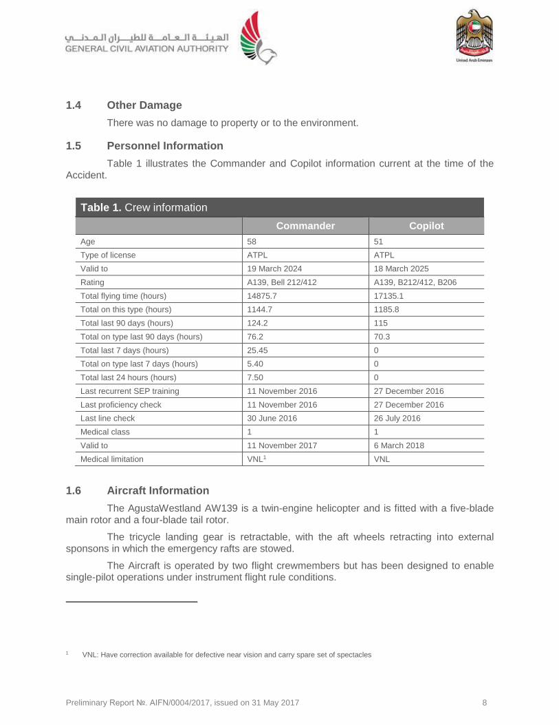
Table 1 illustrates the Commander and Copilot information current at the time of the Accident.
Table 1. Crew information
Commander Copilot
Age 58 51
Type of license ATPL ATPL
Valid to 19 March 2024 18 March 2025
Rating A139, Bell 212/412 A139, B212/412, B206
Total flying time (hours) 14875.7 17135.1
Total on this type (hours) 1144.7 1185.8
Total last 90 days (hours) 124.2 115
Total on type last 90 days (hours) 76.2 70.3
Total last 7 days (hours) 25.45 0
Total on type last 7 days (hours) 5.40 0
Total last 24 hours (hours) 7.50 0
Last recurrent SEP training 11 November 2016 27 December 2016
Last proficiency check 11 November 2016 27 December 2016
Last line check 30 June 2016 26 July 2016
Medical class 1 1
Valid to 11 November 2017 6 March 2018
Medical limitation VNL1 VNL
1.6 Aircraft Information
The AgustaWestland AW139 is a twin-engine helicopter and is fitted with a five-blade main rotor and a four-blade tail rotor.
The tricycle landing gear is retractable, with the aft wheels retracting into external sponsons in which the emergency rafts are stowed.
The Aircraft is operated by two flight crewmembers but has been designed to enable single-pilot operations under instrument flight rule conditions.
1 VNL: Have correction available for defective near vision and carry spare set of spectacles
Preliminary Report №. AIFN/0004/2017, issued on 31 May 2017 9
The passenger cabin accommodates 15 passengers in three seat rows.
The AW139 is equipped with a modular glass cockpit and is fitted with two full authority digital engine control (FADEC) systems. The FADEC systems control two Pratt & Whitney Canada PT6C turboshaft engines, which provide power to the main rotor gearbox.
1.6.1 Aircraft data
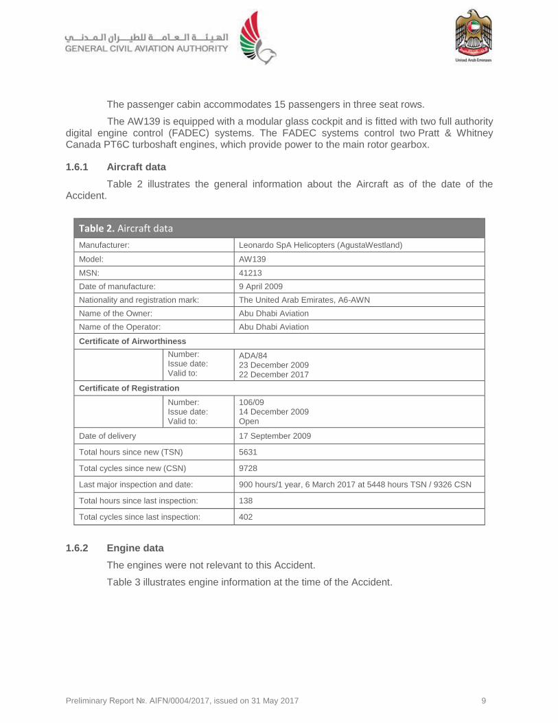
Table 2 illustrates the general information about the Aircraft as of the date of the Accident.
Table 2. Aircraft data
Manufacturer: Leonardo SpA Helicopters (AgustaWestland)
Model: AW139
MSN: 41213
Date of manufacture: 9 April 2009
Nationality and registration mark: The United Arab Emirates, A6-AWN
Name of the Owner: Abu Dhabi Aviation
Name of the Operator: Abu Dhabi Aviation
Certificate of Airworthiness
Number: Issue date: Valid to:
ADA/84 23 December 2009 22 December 2017
Certificate of Registration
Number: Issue date: Valid to:
106/09 14 December 2009 Open
Date of delivery 17 September 2009
Total hours since new (TSN) 5631
Total cycles since new (CSN) 9728
Last major inspection and date: 900 hours/1 year, 6 March 2017 at 5448 hours TSN / 9326 CSN
Total hours since last inspection: 138
Total cycles since last inspection: 402
1.6.2 Engine data
The engines were not relevant to this Accident.
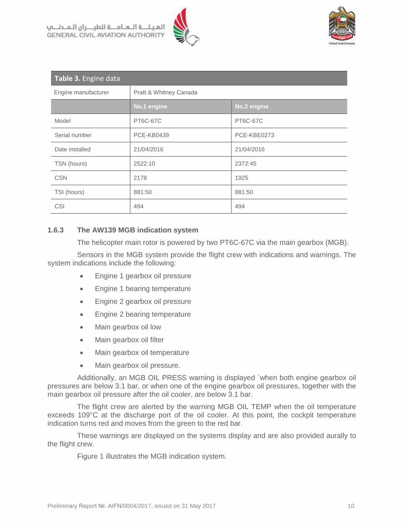
Table 3 illustrates engine information at the time of the Accident.
Preliminary Report №. AIFN/0004/2017, issued on 31 May 2017 10
Table 3. Engine data
Engine manufacturer Pratt & Whitney Canada
No.1 engine No.2 engine
Model PT6C-67C PT6C-67C
Serial number PCE-KB0439 PCE-KBE0273
Date installed 21/04/2016 21/04/2016
TSN (hours) 2522:10 2372:45
CSN 2178 1925
TSI (hours) 881:50 881:50
CSI 494 494
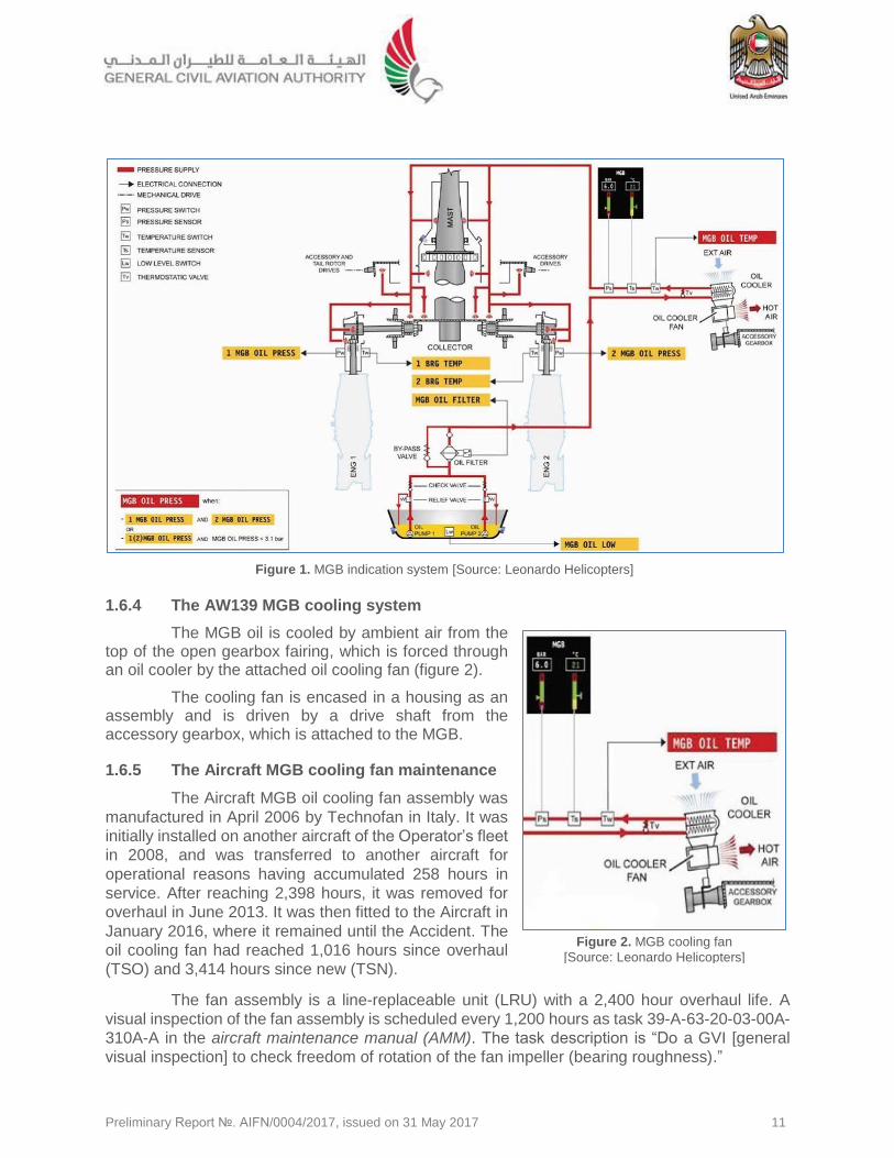
1.6.3 The AW139 MGB indication system
The helicopter main rotor is powered by two PT6C-67C via the main gearbox (MGB).
Sensors in the MGB system provide the flight crew with indications and warnings. The system indications include the following:
Engine 1 gearbox oil pressure
Engine 1 bearing temperature
Engine 2 gearbox oil pressure
Engine 2 bearing temperature
Main gearbox oil low
Main gearbox oil filter
Main gearbox oil temperature
Main gearbox oil pressure.
Additionally, an MGB OIL PRESS warning is displayed `when both engine gearbox oil pressures are below 3.1 bar, or when one of the engine gearbox oil pressures, together with the main gearbox oil pressure after the oil cooler, are below 3.1 bar.
The flight crew are alerted by the warning MGB OIL TEMP when the oil temperature exceeds 109°C at the discharge port of the oil cooler. At this point, the cockpit temperature indication turns red and moves from the green to the red bar.
These warnings are displayed on the systems display and are also provided aurally to the flight crew.
Figure 1 illustrates the MGB indication system.
Preliminary Report №. AIFN/0004/2017, issued on 31 May 2017 11
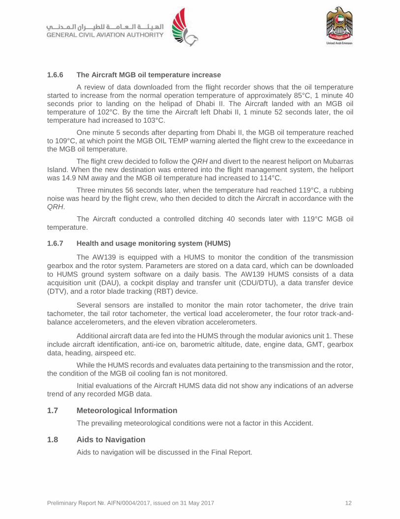
1.6.4 The AW139 MGB cooling system
The MGB oil is cooled by ambient air from the top of the open gearbox fairing, which is forced through an oil cooler by the attached oil cooling fan (figure 2).
The cooling fan is encased in a housing as an assembly and is driven by a drive shaft from the accessory gearbox, which is attached to the MGB.
1.6.5 The Aircraft MGB cooling fan maintenance
The Aircraft MGB oil cooling fan assembly was
manufactured in April 2006 by Technofan in Italy. It was
initially installed on another aircraft of the Operator’s fleet
in 2008, and was transferred to another aircraft for
operational reasons having accumulated 258 hours in
service. After reaching 2,398 hours, it was removed for
overhaul in June 2013. It was then fitted to the Aircraft in
January 2016, where it remained until the Accident. The
oil cooling fan had reached 1,016 hours since overhaul
(TSO) and 3,414 hours since new (TSN).
The fan assembly is a line-replaceable unit (LRU) with a 2,400 hour overhaul life. A
visual inspection of the fan assembly is scheduled every 1,200 hours as task 39-A-63-20-03-00A-
310A-A in the aircraft maintenance manual (AMM). The task description is “Do a GVI [general
visual inspection] to check freedom of rotation of the fan impeller (bearing roughness).”
Figure 1. MGB indication system [Source: Leonardo Helicopters]
Figure 2. MGB cooling fan
[Source: Leonardo Helicopters]
Preliminary Report №. AIFN/0004/2017, issued on 31 May 2017 12
1.6.6 The Aircraft MGB oil temperature increase
A review of data downloaded from the flight recorder shows that the oil temperature started to increase from the normal operation temperature of approximately 85°C, 1 minute 40 seconds prior to landing on the helipad of Dhabi II. The Aircraft landed with an MGB oil temperature of 102°C. By the time the Aircraft left Dhabi II, 1 minute 52 seconds later, the oil temperature had increased to 103°C.
One minute 5 seconds after departing from Dhabi II, the MGB oil temperature reached to 109°C, at which point the MGB OIL TEMP warning alerted the flight crew to the exceedance in the MGB oil temperature.
The flight crew decided to follow the QRH and divert to the nearest heliport on Mubarras Island. When the new destination was entered into the flight management system, the heliport was 14.9 NM away and the MGB oil temperature had increased to 114°C.
Three minutes 56 seconds later, when the temperature had reached 119°C, a rubbing noise was heard by the flight crew, who then decided to ditch the Aircraft in accordance with the QRH.
The Aircraft conducted a controlled ditching 40 seconds later with 119°C MGB oil temperature.
1.6.7 Health and usage monitoring system (HUMS)
The AW139 is equipped with a HUMS to monitor the condition of the transmission
gearbox and the rotor system. Parameters are stored on a data card, which can be downloaded
to HUMS ground system software on a daily basis. The AW139 HUMS consists of a data
acquisition unit (DAU), a cockpit display and transfer unit (CDU/DTU), a data transfer device
(DTV), and a rotor blade tracking (RBT) device.
Several sensors are installed to monitor the main rotor tachometer, the drive train
tachometer, the tail rotor tachometer, the vertical load accelerometer, the four rotor track-and-
balance accelerometers, and the eleven vibration accelerometers.
Additional aircraft data are fed into the HUMS through the modular avionics unit 1. These
include aircraft identification, anti-ice on, barometric altitude, date, engine data, GMT, gearbox
data, heading, airspeed etc.
While the HUMS records and evaluates data pertaining to the transmission and the rotor, the condition of the MGB oil cooling fan is not monitored.
Initial evaluations of the Aircraft HUMS data did not show any indications of an adverse trend of any recorded MGB data.
1.7 Meteorological Information
The prevailing meteorological conditions were not a factor in this Accident.
1.8 Aids to Navigation
Aids to navigation will be discussed in the Final Report.
Preliminary Report №. AIFN/0004/2017, issued on 31 May 2017 13
1.9 Communications
Inter-pilot communications were made via the intercom system. While the Aircraft provided one headset for the passengers in the cabin, communication with the passenger occurred verbally without the use of the intercom.
Communications will be further discussed in the Final Report.
1.10 Aerodrome Landing Site Information
Aerodrome and heliport information will be further discussed in the Final Report.
1.11 Flight Recorders
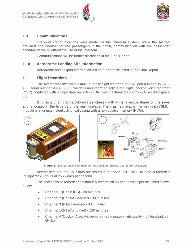
The Aircraft was fitted with a multi-purpose flight recorder (MPFR), part number D51615-
102, serial number 299103-002, which is an integrated solid state digital cockpit voice recorder
(CVR) combined with a flight data recorder (FDR) manufactured by Penny & Giles Aerospace
Ltd.
It consists of an orange colored steel chassis with white reflective stripes on the sides
and is located in the left side of the rear fuselage. The crash survivable memory unit (CSMU)
module is a tungsten steel cylindrical casing with a non-volatile memory (NVM).
Aircraft data and the CVR data are stored in the NVM unit. The FDR data is recorded
in-flight for 25 hours at 256 words per second.
The cockpit voice recorder continuously records on six channels as per the times shown below:
Channel 1 (Cabin ICS) - 30 minutes
Channel 2 (Copilot Headset) - 30 minutes
Channel 3 (Pilot Headset) - 30 minutes
Channel 1-2-3 (Combined) - 120 minutes
Channel 4 (Cockpit Area Microphone) - 30 minutes (high quality - full bandwidth 0-6KHz)
b
Figure 3. Multi-purpose flight recorder and location [Source: Leonardo Helicopters]
a b
Preliminary Report №. AIFN/0004/2017, issued on 31 May 2017 14
Channel 4 (Cockpit Area Microphone) - 120 minutes (low quality - reduced bandwidth 0-3.5KHz).
The MPFR is certified to the requirements of EUROCAE ED-55, ED-56A Amendment 1, ED-112 and FAA TSO-C123a and TSO-C124a. After the MPFR was removed from the Aircraft, it was immediately placed in fresh water to avoid further oxidation damage due to the contact with sea water. The Operator’s avionics facility at Abu Dhabi Airport was utilized to examine the condition of the recorder and to download the data with the assistance of Leonardo Helicopters experts.
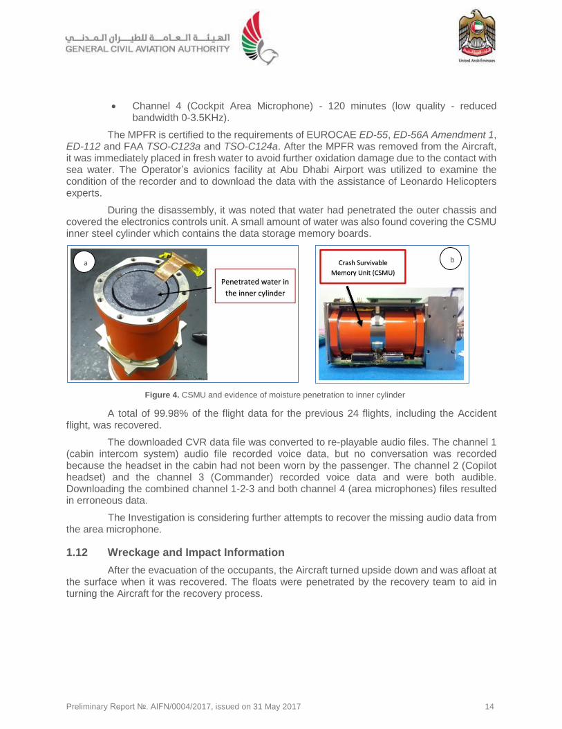
During the disassembly, it was noted that water had penetrated the outer chassis and covered the electronics controls unit. A small amount of water was also found covering the CSMU inner steel cylinder which contains the data storage memory boards.
A total of 99.98% of the flight data for the previous 24 flights, including the Accident flight, was recovered.
The downloaded CVR data file was converted to re-playable audio files. The channel 1 (cabin intercom system) audio file recorded voice data, but no conversation was recorded because the headset in the cabin had not been worn by the passenger. The channel 2 (Copilot headset) and the channel 3 (Commander) recorded voice data and were both audible. Downloading the combined channel 1-2-3 and both channel 4 (area microphones) files resulted in erroneous data.
The Investigation is considering further attempts to recover the missing audio data from the area microphone.
1.12 Wreckage and Impact Information
After the evacuation of the occupants, the Aircraft turned upside down and was afloat at the surface when it was recovered. The floats were penetrated by the recovery team to aid in turning the Aircraft for the recovery process.
Figure 4. CSMU and evidence of moisture penetration to inner cylinder
a b
Preliminary Report №. AIFN/0004/2017, issued on 31 May 2017 15
1.13 Medical and Pathological Information
Post-accident blood tests did not reveal any psychoactive materials that could have degraded crew performance.
1.14 Fire
There was no evidence of pre-or post-impact fire.
1.15 Survival Aspects
1.15.1 The Aircraft ditching system
The Aircraft was equipped with an emergency ditching system, consisting of four
floatation devices. These floats were fitted to the fuselage under protective covers and are
deployed either manually by the flight crew, or automatically during ditching. The floats were
designed to keep the Aircraft afloat to enable safe evacuation of the occupants.
Floats were fitted on each side of the forward fuselage, below the flight deck entrance
doors, and also below the cargo doors at the rear fuselage. A panel on the flight deck center
console allows for arming of the system, which can subsequently be deployed by selecting the
deployment switch on each pilot’s collective grip. When the floats are deployed and inflated, shear
bolts release the float covers from the fuselage.
The forward floats consisted of three independent chambers and two pillow chambers,
which were attached and filled by the forward and rear chamber. Each rear float consisted of four
independent chambers and two pillow chambers at the forward and rear of the float. The intent of
the pillow chambers was to provide sufficient space between the float and the fuselage. Each
pillow was filled through a non-return valve by pressure from the adjacent float chamber.
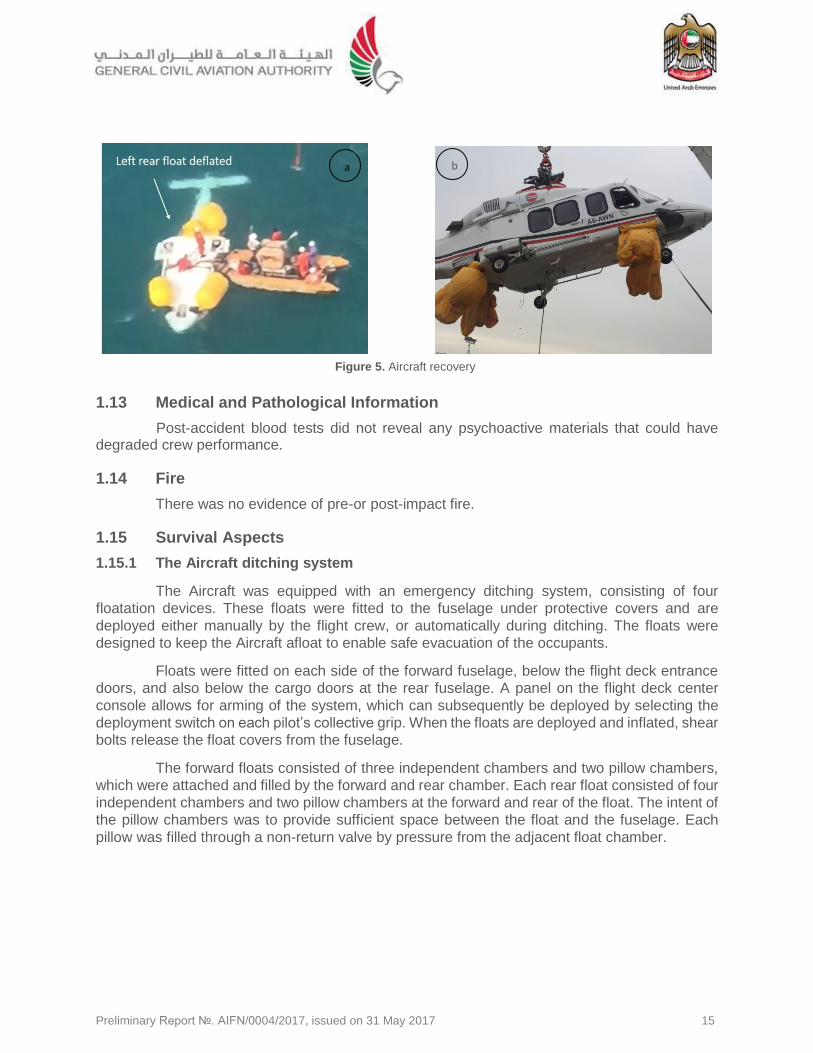
Figure 5. Aircraft recovery
b a
Preliminary Report №. AIFN/0004/2017, issued on 31 May 2017 16
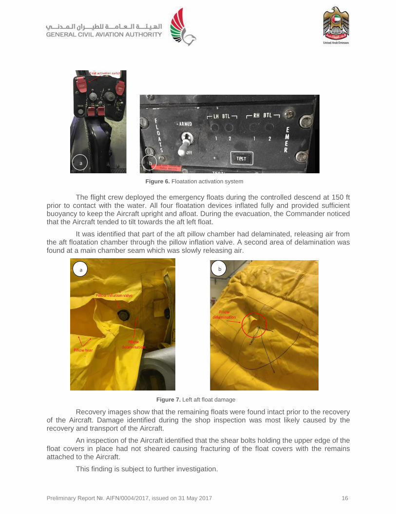
The flight crew deployed the emergency floats during the controlled descend at 150 ft prior to contact with the water. All four floatation devices inflated fully and provided sufficient buoyancy to keep the Aircraft upright and afloat. During the evacuation, the Commander noticed that the Aircraft tended to tilt towards the aft left float.
It was identified that part of the aft pillow chamber had delaminated, releasing air from the aft floatation chamber through the pillow inflation valve. A second area of delamination was found at a main chamber seam which was slowly releasing air.
Recovery images show that the remaining floats were found intact prior to the recovery of the Aircraft. Damage identified during the shop inspection was most likely caused by the recovery and transport of the Aircraft.
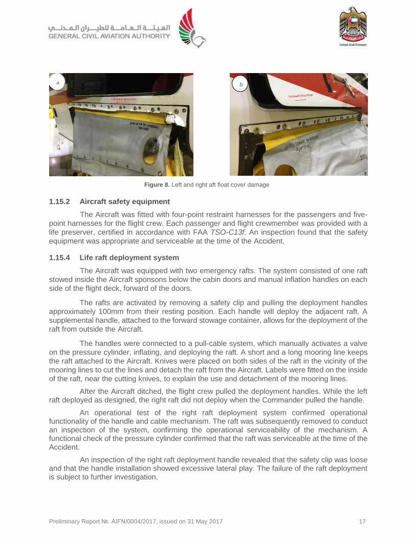
An inspection of the Aircraft identified that the shear bolts holding the upper edge of the float covers in place had not sheared causing fracturing of the float covers with the remains attached to the Aircraft.
This finding is subject to further investigation.
Figure 6. Floatation activation system
Figure 7. Left aft float damage
b a
a
b
b
Preliminary Report №. AIFN/0004/2017, issued on 31 May 2017 17
1.15.2 Aircraft safety equipment
The Aircraft was fitted with four-point restraint harnesses for the passengers and five-
point harnesses for the flight crew. Each passenger and flight crewmember was provided with a
life preserver, certified in accordance with FAA TSO-C13f. An inspection found that the safety
equipment was appropriate and serviceable at the time of the Accident.
1.15.4 Life raft deployment system
The Aircraft was equipped with two emergency rafts. The system consisted of one raft
stowed inside the Aircraft sponsons below the cabin doors and manual inflation handles on each
side of the flight deck, forward of the doors.
The rafts are activated by removing a safety clip and pulling the deployment handles
approximately 100mm from their resting position. Each handle will deploy the adjacent raft. A
supplemental handle, attached to the forward stowage container, allows for the deployment of the
raft from outside the Aircraft.
The handles were connected to a pull-cable system, which manually activates a valve
on the pressure cylinder, inflating, and deploying the raft. A short and a long mooring line keeps
the raft attached to the Aircraft. Knives were placed on both sides of the raft in the vicinity of the
mooring lines to cut the lines and detach the raft from the Aircraft. Labels were fitted on the inside
of the raft, near the cutting knives, to explain the use and detachment of the mooring lines.
After the Aircraft ditched, the flight crew pulled the deployment handles. While the left raft deployed as designed, the right raft did not deploy when the Commander pulled the handle.
An operational test of the right raft deployment system confirmed operational functionality of the handle and cable mechanism. The raft was subsequently removed to conduct an inspection of the system, confirming the operational serviceability of the mechanism. A functional check of the pressure cylinder confirmed that the raft was serviceable at the time of the Accident.
An inspection of the right raft deployment handle revealed that the safety clip was loose and that the handle installation showed excessive lateral play. The failure of the raft deployment is subject to further investigation.
Figure 8. Left and right aft float cover damage
b a
Preliminary Report №. AIFN/0004/2017, issued on 31 May 2017 18
1.15.5 The Aircraft evacuation
The Aircraft
emergency exits consisted
of six escape windows for
the passenger cabin and
two for the flight deck. Once
a seal filler is extracted by a
passenger, each
passenger cabin window
panel can be either pushed
in from the outside or
pushed out from the inside.
The flight deck
escape windows are
opened by first pulling a
seal cord to release the
pressure on the window
seal and then by either
pulling a strap handle
attached to the forward lower corner of the panel from the inside or from the outside by pushing
this corner of the window inwards. The window panels are then thrown out of the opening before
exiting.
The cabin or flight deck doors cannot be used as exits during a ditched landing, as they
may let water into the Aircraft and could damage the emergency floatation system during opening.
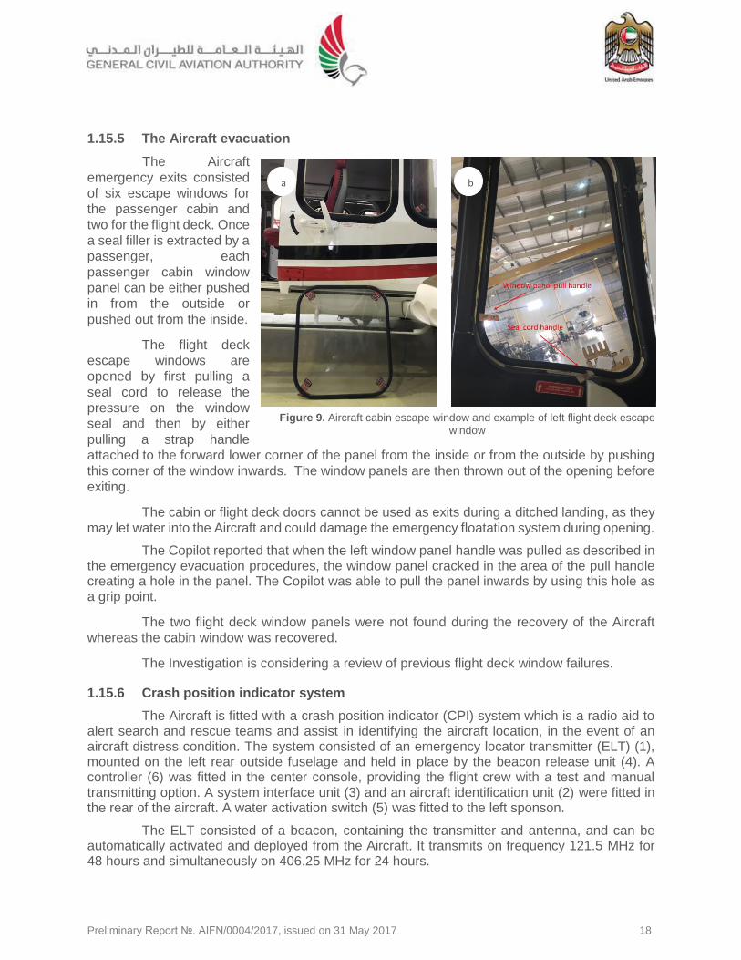
The Copilot reported that when the left window panel handle was pulled as described in the emergency evacuation procedures, the window panel cracked in the area of the pull handle creating a hole in the panel. The Copilot was able to pull the panel inwards by using this hole as a grip point.
The two flight deck window panels were not found during the recovery of the Aircraft
whereas the cabin window was recovered.
The Investigation is considering a review of previous flight deck window failures.
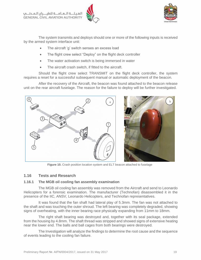
1.15.6 Crash position indicator system
The Aircraft is fitted with a crash position indicator (CPI) system which is a radio aid to alert search and rescue teams and assist in identifying the aircraft location, in the event of an aircraft distress condition. The system consisted of an emergency locator transmitter (ELT) (1), mounted on the left rear outside fuselage and held in place by the beacon release unit (4). A controller (6) was fitted in the center console, providing the flight crew with a test and manual transmitting option. A system interface unit (3) and an aircraft identification unit (2) were fitted in the rear of the aircraft. A water activation switch (5) was fitted to the left sponson.
The ELT consisted of a beacon, containing the transmitter and antenna, and can be automatically activated and deployed from the Aircraft. It transmits on frequency 121.5 MHz for 48 hours and simultaneously on 406.25 MHz for 24 hours.
b
Figure 9. Aircraft cabin escape window and example of left flight deck escape
window
a b
Preliminary Report №. AIFN/0004/2017, issued on 31 May 2017 19
The system transmits and deploys should one or more of the following inputs is received by the armed system interface unit:
The aircraft ‘g’ switch senses an excess load
The flight crew select “Deploy” on the flight deck controller
The water activation switch is being immersed in water
The aircraft crash switch, if fitted to the aircraft.
Should the flight crew select TRANSMIT on the flight deck controller, the system requires a reset for a successful subsequent manual or automatic deployment of the beacon.
After the recovery of the Aircraft, the beacon was found attached to the beacon release unit on the rear aircraft fuselage. The reason for the failure to deploy will be further investigated.
1.16 Tests and Research
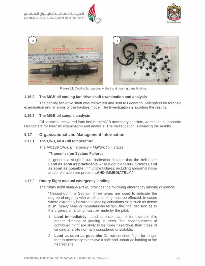
1.16.1 The MGB oil cooling fan assembly examination
The MGB oil cooling fan assembly was removed from the Aircraft and send to Leonardo Helicopters for a forensic examination. The manufacturer (Technofan) disassembled it in the presence of the IIC, ANSV, Leonardo Helicopters, and Technofan representatives.
It was found that the fan shaft had lateral play of 5.3mm. The fan was not attached to the shaft and was touching the outer shroud. The left bearing was completely degraded, showing signs of overheating, with the inner bearing race physically expanding from 11mm to 18mm.
The right shaft bearing was destroyed and, together with its seal package, extended from the housing by 4.8mm. The shaft thread was stripped and showed signs of extensive heating near the lower end. The balls and ball cages from both bearings were destroyed.
The Investigation will analyze the findings to determine the root cause and the sequence of events leading to the cooling fan failure.
Figure 10. Crash position location system and ELT beacon attached to fuselage
b a
Preliminary Report №. AIFN/0004/2017, issued on 31 May 2017 20
1.16.2 The MGB oil cooling fan drive shaft examination and analysis
The cooling fan drive shaft was recovered and sent to Leonardo Helicopters for forensic examination and analysis of the fracture mode. The Investigation is awaiting the results.
1.16.3 The MGB oil sample analysis
Oil samples, recovered from inside the MGB accessory gearbox, were sent to Leonardo Helicopters for forensic examination and analysis. The Investigation is awaiting the results.
1.17 Organizational and Management Information
1.17.1 The QRH, MGB oil temperature
The AW139 QRH, Emergency – Malfunction, states:
“Transmission System Failures
In general a single failure indication dictates that the helicopter Land as soon as practicable while a double failure dictates Land as soon as possible. If multiple failures, including abnormal noise and/or vibration are present LAND IMMEDIATELY.”
1.17.2 Rotary flight manual emergency landing
The rotary flight manual (RFM) provides the following emergency landing guidance:
“Throughout this Section, three terms are used to indicate the degree of urgency with which a landing must be effected. In cases where extremely hazardous landing conditions exist such as dense bush, heavy seas or mountainous terrain, the final decision as to the urgency of landing must be made by the pilot.
1. Land immediately: Land at once, even if for example this means ditching or landing in trees. The consequences of continued flight are likely to be more hazardous than those of landing at a site normally considered unsuitable.
2. Land as soon as possible: Do not continue flight for longer than is necessary to achieve a safe and unhurried landing at the nearest site.
Figure 19. Cooling fan assembly shaft and bearing parts findings
a b
Preliminary Report №. AIFN/0004/2017, issued on 31 May 2017 21
3. Land as soon as practicable: Land at the nearest aviation location or, if there is none reasonably close, at a safe landing site selected for subsequent convenience.”
1.17.3 Rotary flight manual ditching
The Investigation will discuss the ditching procedures in the Final Report.
1.18 Additional Information
The Final Report will include the necessary additional information.
1.19 Useful or Effective Investigation Techniques
This Investigation is conducted in accordance with the Legislation and Civil Aviation Regulations of the United Arab Emirates, and with the AAIS approved policies and procedures, and in accordance with the Standards and Recommended Practices of Annex 13 to the Chicago on International Civil Aviation.
Preliminary Report №. AIFN/0004/2017, issued on 31 May 2017 22
2. Ongoing Investigation Activities The Investigation is ongoing and will include further examination and analysis of:
The root cause and sequences of the MGB cooling fan assembly failure
The MGB cooling fan assembly reliability
Floatation device damage
Raft deployment failure
Flight deck escape window condition
The Operator’s ditching procedures and training
The activation of the ELT
The MGB oil temperature indication system
The MPFR water resistance
Any other safety aspects that may arise during the course of this Investigation.
The Investigation will conduct an in-depth analysis of:
Contextual factors
Human factors
Organizational factors.
Preliminary Report №. AIFN/0004/2017, issued on 31 May 2017 23
3. Safety Concerns and Actions 3.1 Safety Actions Taken
The Accident and the initial inspection prompted the Operator to conduct an AW139 fleet inspection for visible damage on other cooling fan assemblies. This inspection included eight aircraft and was completed on 7 May 2017. The scope of the inspection was associated with the 1,200 hours inspection in accordance with the maintenance program task 39-A-63-20-03-00A-310A-A ̶̶ General Visual Inspection of MGB Oil Cooling Fan for freedom of rotation of the fan impeller.
No further cooling fan defects or degradation of the fan impeller bearing were detected.
This Preliminary Report is issued by:
The Air Accident Investigation Sector General Civil Aviation Authority The United Arab Emirates. E-mail: [email protected] Fax: +971 2 4491599