Embed Size (px)
Citation preview

CHAPTER 8 – AIR BRAKE SYSTEM
WAGON MAINTENANCE MANUAL
Page 1 of 109
CHAPTER 8
AIR BRAKE SYSTEM
801. CLASSIFICATION OF AIR BRAKE SYSTEM
On the basis of type of release, air brake system is classified as:
Direct release air brake system Graduated release air brake system
Both Direct and Graduated release are further available in two forms viz.
Single pipe and Twin pipe
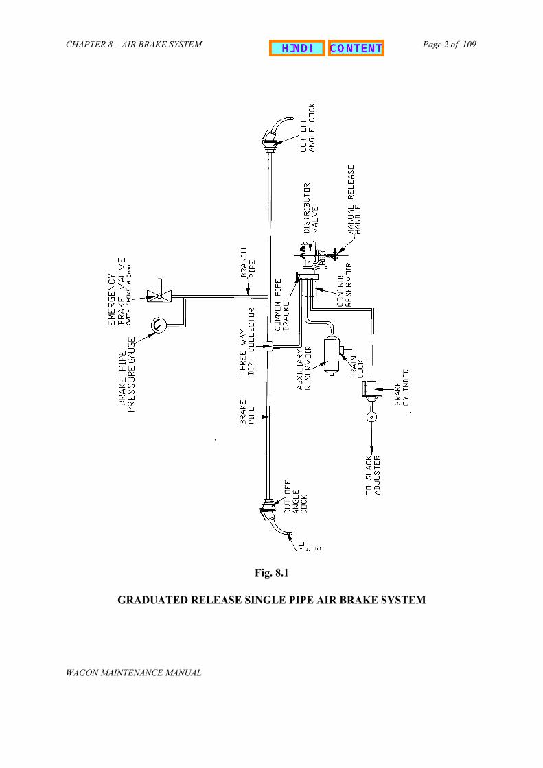
The diagram shown in fig. 8.1 illustrates the schematic layout of air brakeequipment on the under frame of freight stock. As shown in figure, the single pipegraduated release air brake system consist of following components:-
i) Distributor valveii) Common pipe bracket with control reservoir.iii) Auxiliary reservoir.(100 Litres)iv) Three way centrifugal dirt collector.v) Isolating cock.vi) Brake cylinder (355mm diameter).vii) Cut off angle cock (32mm size on either ends of brake pipe).viii) Air brake hose coupling (32mm for brake pipe)..ix) Brake pipe (32mm dia).x) Branch pipes from BP to brake equipment (20mm bore).xi) Guard emergency brake valve.xii) Pressure gauges for BP
802. PRINCIPLE OF OPERATION OF SINGLE PIPE GRADUATED RELEASE AIR BRAKE SYSTEM
The Air Brake goods stock on IR is at present fitted with single pipe graduatedrelease air brake system. In single pipe, brake pipes of all wagons are connected. Alsoall the cut off angle cocks are kept open except the front cut off angle cocks of BP ofleading loco and rear end cut off angle cock of BP of last vehicle. Isolating cock on allwagons are also kept in open condition. Auxiliary reservoir is charged through distributorvalve at 5kg/cm2.
CHAPTER 8 – AIR BRAKE SYSTEM
WAGON MAINTENANCE MANUAL
Page 2 of 109
Fig. 8.1
GRADUATED RELEASE SINGLE PIPE AIR BRAKE SYSTEM

CHAPTER 8 – AIR BRAKE SYSTEM
WAGON MAINTENANCE MANUAL
Page 3 of 109
A. Charging stage
Fig. 8.2 C
During this stage, brake pipe charges control reservoir and auxiliaryvalve. At this stage, brake cylinder gDistributor valve.
B. Application Stage
Fig. 8.3 AP
HARGING
is charged to 5kg/cm2 pressure which in turn reservoir to 5 kg/cm2 pressure via distributorets vented to atmosphere through passage in
PLICATION

CHAPTER 8 – AIR BRAKE SYSTEM
WAGON MAINTENANCE MANUAL
Page 4 of 109
For application of brakes, the pressure in brake pipe has to be dropped. This isdone by venting air from driver’s brake valve. Reduction in brake pipe pressure positionsthe distributor valve in such a way that the control reservoir gets disconnected frombrake pipe and auxiliary reservoir gets connected to brake cylinder. This results inincrease in air pressure in brake cylinder resulting in application of brakes. Themagnitude of braking force is proportional to reduction in brake pipe pressure
Note: 1. Brake Application takes places when Brake pipe pressure is dropped.2. The drop of pressure may be a) Intentional and b) Accidental.
C) Release stage
Fig. 8.4
For releasing brakes, the brake pipcompressor through driver’s brake valve. Taway that auxiliary reservoir gets isolatedvented to atmosphere through distributor va
AIR BRAKE SUB ASSEMBLIES
803. COMMON PIPE BRACKET
Common pipe bracket is permanenThe distributor valve along with the inteisolating cock is mounted on one face of this mounted on the other face of the Comm
The Common pipe bracket has bsuitable for use with any make of distributo
Common pipe bracket is a sturdy cintermediate piece mounting face with accleading to the appropriate ports of the dist
RELEASE
e is again charged to 5 kg/cm2 pressure byhis action positions distributor valve in such a from brake cylinder and brake cylinder islve and thus brakes are released
tly mounted on the under frame of a vehicle.rmediate piece (sandwich) which houses thee common pipe bracket. The control reservoiron pipe bracket.
een evolved with the purpose of making itr valve adopted on Indian Railways.
asting with internal air passages, matching theurately profiled air cavities and flanged portsributor valve.

CHAPTER 8 – AIR BRAKE SYSTEM
WAGON MAINTENANCE MANUAL
Page 5 of 109
Branch pipes to the brake pipe and brake cylinders are fitted on the appropriateports on the common pipe bracket. The advantage of fitting a common pipe bracket isto remove the distributor valve for repair or replacement without disturbing the pipeconnections.
804. INTERMEDIATE PIECE (SANDWICH PIECE)
Intermediate piece serves the purpose of blanking all the other ports on thecommon pipe bracket front face other than required for a particular make of distributorvalve. Each type of distributor valve is mounted on the common pipe bracket with itsown intermediate piece (sandwich).
Intermediate piece is mounted on the common pipe bracket face with a commongasket and the distributor valve is fastened to the intermediate piece. Isolating cock fordistributor valve, which is housed in the intermediate piece is for isolating the distributorvalve in case of malfunctioning or for disconnecting the brake pipe pressure. Isolatingcock on intermediate piece has a built in venting arrangement.
805. BRAKE PIPE HOSES
Fig. 8.5In order to connect two successive wagons, the brake pipes (BP) installed on the
underframe are fitted with flexible hoses. The hoses are named as BP hose.
806. BRAKE PIPE COUPLING
To connect subsequent wagons, the hoses of BP are screwed to coupling andhose nipple by means of stainless steel `Bend it’ type clips. The coupling is speciallydesigned in the form of palm end and hence also known as palm end coupling. For easyidentification the couplings are engraved with letter BP and coupling heads are paintedgreenNote: Design, controlling dimensions, material and specification of components shall
conform to the latest revision of RDSO drg. number SK-73547 for BP andappendix F of 02 ABR 94 of RDSO specification. The air brake hose couplings are provided in the brake pipe line throughout the
train for connecting the brake pipe of adjacent wagons to form the complete rake. EachAir Brake Hose coupling consists of a specially manufactured rubber hose clamped overa nipple on one end and a coupling head on the other end. Rubber sealing washers areprovided on the outlet port of the coupling head.
Since a joint is formed at the coupling head, leakage may take place, through it.Therefore it is necessary to subject the hose coupling of brake pipe to leakage test.

CHAPTER 8 – AIR BRAKE SYSTEM
WAGON MAINTENANCE MANUAL
Page 6 of 109
A. TOOLS AND EQUIPMENT
a) Test stand (Fig. 8.6)
Test stand for testing of the hose coupling consists of the following main equipment1) Supply of compressed air at – 10 Kg/cm2
2) Isolating cock – 1a and 1b3) Exhaust cock – 1c4) Main reservoir5) Pressure gauge
6a for main reservoir 6b for flexible hose
6) Flexible hose - for connecting hose coupling for immersing in to water.7) Water tub with safety cage – for checking leakage from hose coupling.8) Dummy coupling head.
b) TEST PROCEDURE
For testing the hose coupling the steps given below should be followed:
i. Use a dummy coupling head to block the outlet port of the hose coupling.ii. Connect to hose coupling under test to the end of flexible hose.iii. Open isolating cock 1(a)iv. Adjust pressure regulator (2) so that pressure gauge (6a) shows 10Kg./cm2 air
pressure.v. Immerse the hose coupling assembly completely in the tub of water.vi. Open isolating cock (1b) and see that (6b) shows 10 Kg/cm2 pressure.vii. Observe leakage, if any from all parts of the hose coupling.viii. Close the isolating cock 1(b).ix. Disconnect the hose coupling from test bed.x. If the leakage is observed through the coupling head, replace the gasket and test
again.xi. If leakage persist even after change of gasket the coupling head is unserviceable
and complete assembly shall be rejected. However if leakage occurs at thehose nipple or coupling end hose joint the clamp should be attended/replaced tomake the assembly leak proof.
c) SAFETY PRECAUTIONS
Specified tools and fixtures should be used for connecting and disconnecting thehose coupling with the air supply.
While testing the hose coupling before charging it to 10kg/cm2 pressure, the tubeshould be covered and locked with a protective cage.
Exhaust the pressure from the hose coupling under test, before lifting the safetycage and uncoupling it.
After testing, the hose assembly shall be stored in a dry and clean space. The inletand outlet port must be plugged with protective cap to prevent entry of dust andforeign particles inside the hose coupling.

CHAPTER 8 – AIR BRAKE SYSTEM
WAGON MAINTENANCE MANUAL
Page 7 of 109
1 ¼
“ bs
b so
cket
toco
uple
hos
eco
uplin
g ni
pple
end
FLEX
IBLE
HO
SEH
IGH
PR
ESSU
RE
(10
KG/C
M2 C
AL)
CH
ARG
ING
PRES
SUR
E G
AUG
E
EXH
AUST
CO
CK
1
ISO
LATI
NG
CO
CK
6b
MAI
NR
ESER
VOIR6a
MR
1b2
1a
ISO
LATI
NG
CO
CK
PRES
SUR
ER
EDU
CER
Fig
. 8.6
T
ES
TIN
G O
F H
OS
E C
OU
PL
ING

CHAPTER 8 – AIR BRAKE SYSTEM
WAGON MAINTENANCE MANUAL
Page 8 of 109
807. CUT OFF ANGLE COCK
Fig. 8.7Cut off angle cocks are provided on the air brake system to facilitate coupling
and uncoupling of air hoses (i.e. brake pipe). When the handle of the cut off angle cockis placed in closed position it cuts off the passage of compressed air, there byfacilitating coupling and uncoupling action.
If coupling action has to be performed on a given rake, ensure that the cut offangle cock provided at the end of the brake pipes are closed. By doing this thecompressed air gets cut off and does not enter into the brake pipe air hose . The airhoses without compressed air can thus easily be coupled without any jerk. Similarlyduring uncoupling the cut off angle cocks of subsequent wagons should be closed. Bydoing so the air present in the brake pipe air hose gets leaked through the vent providedin the body of the cut off angle cock. Finally the air hoses get emptied and thus can beeasily uncoupled without any jerk.
The cut off angle cock consists of two parts viz. cap and body which are securedtogether by bolts. The cap and the body together hold firmly the steel ball inside it,which is seated on rubber seat. The ball has a special profile with the provision of agroove at the bottom portion for venting the air to the atmosphere.
On the top surface of the body a bore is provided for placing the stem, to whicha self locking type handle is fixed. When the handle is placed parallel to the cut offangle cock the inlet port of the cut off angle cock body is connected to the outlet port,through the hole provided in steel ball. Thus air can easily pass through the cock. Thisposition of the handle is known as open position. When the handle is placedperpendicular to the cock body the steel ball gets rotated and the spherical and grooveportion of the ball presses against the sealing ring at inlet and outlet port, there byclosing the passage of inlet air and venting the outlet air through the vent hole. Thisposition of the handle is known as closed position.
With the stem one leaf spring is provided which presses the operating handledownwards. By virtue of this, handle gets seated in deep grooves at ON/OFF positionresulting in a mechanical lock.

CHAPTER 8 – AIR BRAKE SYSTEM
WAGON MAINTENANCE MANUAL
Page 9 of 109
Under normal working conditions, the handle of all cut off angle cock of BP arekept open except the rear end angle cock (BP). This facilitates in charging the completeair brake system with compressed air supplied by the compressor housed in thelocomotive. Cut off angle cock fitted on the brake pipe is painted green.
Note: The dimension and tolerances of cut off angle cock shall be as indicated in latestrevision of RDSO drawing nos. WD-88123-S-01 and WD-88123-S-02.
Since a number of manufacturers exist for air brake equipment and component,refer to concerned original manufacturer’s maintenance manual for part no. anddescription of spares.
A. OVERHAULING OF CUT OFF ANGLE COCK
These angle cocks are of ball -type ensuring better sealing against leakage andfacilitate ease of operation. During overhauling, it is dismantled for cleaning, replacementof parts and checking for effective functioning.
The cut -off angle cock is to be completely dismantled and overhauled duringPOH or when there is some specific trouble.
a) TOOLS & EQUIPMENT
The following tools and fixtures are required for overhauling
(I) Single end spanner.1) A/F 17 for M10 nut pivot screw.2) A/F 10 for M6 nut.
(II) Screw driver 12”/300 mm long.(III) Vice.(IV) Light hammer.
b) PROCEDURE
Dismantling
Hold the cut – off angle cock in vice. Unscrew the lock nut from the stem. Take out the handle assembly (The handle assembly need not be
dismantled further unless it is necessary to change the plate spring i.e. if itis found, heavily rusted, pitting crack or the spring is permanent set).
Unscrew the four hexagonal bolts and spring washers. Detach cap from the body. Remove ‘O’ ring and ball seat from the cap. Turn the stem in such a way that the ball can be pulled from the stem. Slightly hammer the stem at its top and take out the stem through the
bore of the body. Remove the ball seat from the body.
CHAPTER 8 – AIR BRAKE SYSTEM
WAGON MAINTENANCE MANUAL
Page 10 of 109
c) Cleaning of Parts
Clean out side portion of the body and cap with wire brush. Direct a jet of air to remove the dust. Clean all metallic parts with kerosene oil and wipe dry.
d) Replacement of Parts
Replace all rubber parts. Replace spring-washer, nut & bolts in case they are excessively corroded or
defective. Replace handle spring if it is found heavily rusted, is having pitting crack or
is permanently set (Dismantle the handle assembly, and fit a new springalong with a snap head rivet).
Replace stainless steel ball if found with scratch marks on the outer surfaceor dented.
e) Assembly
Insert the two ‘O’ rings in their respective grooves on the stem. Keeping the threaded end of the stem first, insert the stem into the body
through the bore of the body. Place one ball seat in its groove inside the body. Position the ball after correctly aligning its venting slot in the bore of the
body. Place the second ball seat and ‘O’ ring in their respective positions on the
cap. Secure the body and cap by Hex. Hd. Bolt (M6) and spring washer (for M6). Place the handle assembly on the stem and secure it with Hex. Hd. Nut
(M10). During assembly apply a light coat of shell MP2 or equivalent grease on the
external surface of the threads and the ball.
B. TESTING OF CUT–OFF ANGLE COCK
a) TOOLS AND EQUIPMENT
i. Test Benchii. Compressor to build pressure more than 10 kg/cm2.iii. Single ended spanner as per IS 2027
a) Across face 17 (for M10 lock nut) - 1 No.b) Across Face 13 (for M8 studs) 2 No.
iv. Screw Driver –300mm, 1 No.v. 1 ¼ “ BSP dummy Plug with seal.vi. Dummy plug for angle cock.

CHAPTER 8 – AIR BRAKE SYSTEM
WAGON MAINTENANCE MANUAL
Page 11 of 109
b) TEST PROCEDURE
Following test procedure should be adopted step by step for performing theleakage test.
i. Mount the angle cock on the base of the test bench (Part No. 7 of the figure ofthe test bench).
ii. Move the handle to the closed position.iii. See that cock (1e) and (1c) are in closed position.iv. Now open cock 1(a) and 1(b) till MR indicates a pressure of 10 Kg/Cm2.v. If necessary, adjust pressure regulator (2) to maintain the pressure at 10
kg/Cm2.vi. Open cock (1c) and check the leakage with soap solution. There should not be
any leakage.vii. Check pressure drop in gauge (6b) there should not be any leakage from flange
joints, vent and outlet port of the angle cock.viii. Close cock (1c) and tighten the dummy plug and seal the outlet of the angle
cock.ix. Move the handle to the open position. Open cock 1c.x. Check for leakage from body and cap joint, vent and all over the stem periphery
using soap water. No leakage is permissible.xi. Move the handle to closed position and notice a short blast of air through
the vent.xii. Close cock 1c then Open cock (1d) and exhaust the pressure to zero.xiii. Remove the angle cock.xiv. Report results of the test.
e) SAFETY PRECAUTIONS
Specified tools and fixtures should be used for assembly and disassemblyoperations.
The small metal parts like leaf spring, nut, bolts, washers, screws etc shouldbe kept in a safe place and replaced in case found defective.
Inlet and outlet port of the tested angle cock should be plugged withprotection cap to prevent entry of dust and moisture inside the cut off anglecock.
Ball should be handled carefully to avoid any damage on its surface.
Threaded portion of body and cap should not be damaged at the time ofdismantling.

CHAPTER 8 – AIR BRAKE SYSTEM
WAGON MAINTENANCE MANUAL
Page 12 of 109
808. BRAKE CYLINDER
(Note: Anti-rattler ring shall be provided on brake cylinder for passenger stock)
Fig. 8.8 BRAKE CYLINDER
On every wagon fitted with air brake system one brake cylinder is provided foractuating the brake rigging for the application and release of brakes.
During application stage the brake cylinder receives pneumatic pressure from theauxiliary reservoir after being regulated by the distributor valve. There after the brakecylinder develops mechanical brake power by outward movement of its piston assembly.To transmit this power to the brake shoe, the push rod of piston assembly is connectedto the brake shoe through a system of levers to amplify and transmit the brake power.During release action of brakes the compression spring provided in the brake cylinderbrings back the rigging to its original position.
The cylinder body is made out of sheet metal or cast iron and carries themounting bracket, air inlet connection, ribs and flange. To the cylinder body, a domecover is fitted with the help of bolts and nuts. The dome cover encloses the spring andthe passage for the piston trunk, which is connected to the piston by screws. The pistonis of cast iron having a groove in which piston packing is seated. Piston packing ofrubber material which is of oil and abrasion resistant and unaffected by climaticchanges. It is snap fit to the piston head and has self lubricating characteristic whichensures adequate lubrication over a long service period and extends seal life considerably
The piston packing also seals the air - flow from the pressure side to the otherside and is guided by the wear ring. The wear ring prevents the friction between cylinderbody and the piston head. The piston sub assembly incorporates a push rod, which canarticulate and take minor variations in alignment during fitment/operation.

CHAPTER 8 – AIR BRAKE SYSTEM
WAGON MAINTENANCE MANUAL
Page 13 of 109
Note: The dimension and tolerances of brake cylinder shall conform to the latest revision ofRDSO drawing number WD-92051–S 06, WD-92051-S-07, WD-92051-S-08, WD-92057-S-09, WD 92051 –S-09 and WD 94048-s-01.
A. OVERHAULING OF BRAKE CYLINDER
Brake cylinder has to be thoroughly overhauled for efficient and reliable troublefree performance during its prolonged service life. The complete overhauling of the brakecylinder is to be carried out during POH or when there is some specific trouble.
a) TOOLS & EQUIPMENT
Sr. No. Description
1. Torque Wrench 0-3 Kg range2. Double End Spanner 24x27 mm across face (For M16)3. Double End Spanner across face 13x14 (For M12)4. Socket Wrench 19 mm (For M12)5. Screw Driver 12" (300 mm)6. Special fixture (Screw press/ Pneumatic)7. Gauge for examining bore of the cylinder
b) Dismantling of Brake Cylinder
Before dismantling the dome cover insert a rounded head pin of 12x25 long andsecure one of the hole in the piston trunk for the purpose of safety to prevent domecover working out of the piston rod due to the cylinder return spring force while openingthe dome cover with the help of a special fixture clamp the dome cover.
Unscrew the Hex. Hd. nut and take out the spring washer on the domecover.
Turn the handle of the fixture to release the clamp and withdraw the holdingclamp of the fixture till the return spring inside the cylinder is fully expandedand free.
Remove the dome cover and take out the return spring. Remove the bush on the rod and brake cylinder. Remove the piston rod sub-assembly, piston ring packing, wear ring and
slide out the anti rattler ring from the piston rod. Unscrew the CSK, head screw and separate the piston, pin, piston trunk &
piston rod assembly. Unscrew the brake cylinder plug at the rear end.
c) Cleaning of Parts
Blow a jet of air to clean the dust on the external surface. Clean the metallic parts using wire brush and kerosene oil. Clean the internal parts with nylon bristle brush. Clean piston packing, wear ring and rubber parts with soap water solution.

CHAPTER 8 – AIR BRAKE SYSTEM
WAGON MAINTENANCE MANUAL
Page 14 of 109
d) Replacement of Parts
Replace return spring in case of crack, kinks or permanent set. Replace the brake cylinder body if found with deep marks, heavily corroded,
or the bore is worn uneven or having ovality. Replace all rubber parts. If piston trunk is worn excessively it should be replaced. Replace piston and piston rod for damages, bent etc. Replace dome cover for damage, damaged hole etc.
e) Inspection and Repairs of the Parts
Examine visually that the internal surface is free from scratches, rust. Brake cylinder bore to be checked for ovalness with proper gauge. Check the characteristics of the return spring. Piston trunk to be checked for wear and tear. Pin, piston rod should be checked for wear. Dome cover shall be checked for excessive wear and if worn build up with
welding and thereafter re-bore to the required size. Gauge, bush bore of the piston rod, replace it if worn.
f) Testing Of Brake Cylinder Body for Leakage
Before assembly, put dummy plate on the dome side and subject the brakecylinder for hydraulic pressure of 10 kg/cm2 for 5 minutes. No leakage ispermitted.
g) Assembly of Brake Cylinder
Assemble piston rod, pin, piston trunk on piston, tighten CSK screws topiston trunk and piston.
Slide anti -rattler ring from the piston front side. Assemble piston return spring on the piston head and insert the dome cover
over the piston trunk. Insert φ 12 x 25 mm long head pin into the hole provided in the extended
portion of the trunk. Smear the piston head & inside the cylinder body with MP 2 grease or
equivalent. Ease the packing into the cylinder with a wooden spatula with a round nose
and round edge to avoid damage to the piston packing. Push the piston assembly approximately to the central position of the
cylinder. With the help of special fixture, bring down the dome cover on to the
cylinder body and fasten the 8 Hex. HD bolt, nut and spring washer withrequired torque.
Take out the φ 12x25 long pin from the piston trunk hole. Fit back the plug at the rear of the cylinder. Fit the new piston packing and wear ring.

CHAPTER 8 – AIR BRAKE SYSTEM
WAGON MAINTENANCE MANUAL
Page 15 of 109
B. TESTING OF BRAKE CYLINDER
a) BRAKE CYLINDER TEST BENCH (Fig. 8.9)
Test bench consists of the following main partsi. 3 nos. of isolating cocksii. Isolating cock with 1mm chokeiii. Pressure reducing valve
Fig. 8.9 TEST BENCH FOR BRAKE CYLINDER
iv. 2 Nos. Pressure gaugesv. Pipe line filtervi. Brake cylinder pressure mounting base with safety guardvii. Air reservoir
b) TOOLS REQUIRED DURING TESTING
i. Torque wrench range (2-3 kgM capacity) – One number.ii. Double ended spanner (M16) across face 24x27 – One number.iii. Socket wrench (M12) across face 19 – One Number.iv. Double ended spanner (M8) across face 13x14 – One number.v. Screw Driver – 300mm – One number.
After the overhauling of the brake cylinder, it is mounted on the testbench and tested. It should be operated a few times on the test bench to easethe piston. Each brake cylinder after its maintenance and overhaul shall besubjected to the following tests on the test bench.
Arrangement as shown in Fig. 8.9 is used for testing.

CHAPTER 8 – AIR BRAKE SYSTEM
WAGON MAINTENANCE MANUAL
Page 16 of 109
c) STRENGTH TEST
Follow the procedure as given below.
i. Place the brake cylinder on base (4) and connect the line to brakecylinder. Brake cylinder stroke should be free.
ii. Close the safety guard, close the cock (Ic).iii. Open cock (1b) and let reservoir pressure reach 10 Kg/cm2. Check the
pressure in MR gauge (3a).iv. Open cock (2) till the pressure reaches 6 Kg/cm2 in pressure gauge
(3b).v. Close the cock (2) and wait for 2 minutes.vi. Open cock (1c).
The above test should be done with the safety guard.
d) PRESSURE TIGHTNESS TEST
Follow the following procedure.
i. Mount the cylinder on the test stand and tighten the mounting bolts &nuts.
ii. Set the brake cylinder stroke at 85 + 10 mm.iii. Open cock (2) and let the pressure gauge (3b) reaches 0.8 Kg/cm2.iv. Close the cock (2) and wait for 1 minute till the pressure stablise in
gauge (3b).v. Check for the pressure drop which should not be more than 0.1 Kg/cm2
in 10 minutes.vi. Open cock (1 c)vii. Repeat the test at 130 + 10 mm piston stroke and 3.8 Kg/cm2pressure.
Close cock (2) open cock (1c). Remove the brake cylinder.
If pressure is not correct or leakage rate is higher, dismantle the brakecylinder and examine piston packing wear ring for proper fitment. Examine plugfor leakage. Reassemble the components and retest.
e) PAINTING
The exterior of the brake cylinder shall be painted with black enamel paint.
f) STORING
Assembled or dismantled brake cylinder should be stored in such a way toprevent the following.
Flange surface should be prevented from damages. Inlet and outlet port should be plugged with protective cap to prevent the entry
of dust and moisture inside the brake cylinder.
CHAPTER 8 – AIR BRAKE SYSTEM
WAGON MAINTENANCE MANUAL
Page 17 of 109
g) PRECAUTIONS DURING TESTING
Safety Guard should be used during the strength test. Assembled or dismantled brake cylinder should be stored in such a way to
prevent the following:
i. Flange surface should be prevented from damage.ii. Inlet port should be plugged with a protective cap to prevent the entry of
dust and moisture inside the brake cylinder. Avoid damage to piston packing by dull or sharp edged thin bladed tool. Fit 12 dia, 25 mm long round headed pin on the hole provided in the extended
portion of trunk surface before loosening the cover bolts. Excessive lubrication of the cylinder must be avoided. Specified tools and fixtures should be used for handling, mounting and removing
the brake cylinder from the test bench. The small metal parts like springs, washer, screws, nuts, bolts, washers should be
kept in a safe place and replaced in case found defective.
809. DIRT COLLECTOR
A. FUNCTION OF DIRT COLLECTOR
Dirt Collector is placed in the brake pipe line at a point from where a branch istaken off to the distributor valve. As the name indicates the purpose of the dirt collectoris to protect the distributor valve and the auxiliary reservoir by trapping dust and otherforeign matters from the compressed air before it enters into the distributor valve andthe auxiliary reservoir. This action is achieved by centrifugal action. Hence it is alsoknown as centrifugal dirt collector. The dirt collector ensures inter vehicular full flow ofdirt free compressed air to the auxiliary reservoir and the distributor valve through thebranch pipes. When the air enters into the body of the dirt collector tangentially throughport A’ it passes down through inverted case in a spiral path. Due to the velocity of airflow, dirt particles get flung outwards. There after they slide down & collect at thebottom.
B. SALIENT FEATURES OF DIRT COLLECTOR
The air entering into the dirt collector from the brakepipe is guided throughsuitably shaped passage in dirt collector body to produce centrifugal flow. The air is thenfiltered through additional filter assembly before it is passed to outlet on branch pipeside to provide dust proof air to the distributor valve /auxiliary reservoir after arrestingfine dust particles. The dirt contained in the air descends down and gets deposited in thedirt chamber. However, fine particles are also arrested in the filter assembly. The dustparticles accumulated in the dirt chamber are removed by opening the drain plug. Rubbergasket is provided between the cover and housing to prevent leakage. Similarly leatherwasher is provided between the housing and the drain plug to prevent leakage.

CHAPTER 8 – AIR BRAKE SYSTEM
WAGON MAINTENANCE MANUAL
Page 18 of 109
Note: The dimensions and tolerance of dirt collector shall be as indicated inlatest revision of RDSO drawing number WD-92051-S-03, WD-92051-S-04and WD-92051-S-05.
The dirt collector is to be completely dismantled and overhauled once in 5 yearsor after 8 lakhs kilometers whichever is earlier or when there is some specific trouble.
C. TOOLS AND FIXTURES
The following tools and fixtures are required for overhauling:
a) Spanner 19 x 22mmb) Vice.c) Screw Driver
D. PROCEDURE FOR MAINTENANCE
I. Disassembly
Hold the dirt collector in vice. Loosen drain plug and remove it completely from housing. Remove top cover and seal by loosening four hexagonal nuts and removing
hexagonal bolts. Remove filter from body.
II. Cleaning of Parts
Clean all metallic parts using brush and kerosene oil. Clean filter with soap water. Check all parts for any damage.
III. Replacement of Parts
Replace sealing ring and gasket. Replace filter if found punctured or damaged. Check spring washer and replace in case defective or excessively corroded.
IV. Assembly
Assemble body after smearing grease. Locate filter in position and assemble top cover with new gasket. Fix hexagonal bolts/nuts along with the spring washer. Fix new sealing ring to the bottom and assemble drain plug.

CHAPTER 8 – AIR BRAKE SYSTEM
WAGON MAINTENANCE MANUAL
Page 19 of 109
E. TESTING OF DIRT COLLECTORCentrifugal Dirt Collector is provided at the junction of the main pipe and branch
pipe in brake pipes. There are three purposes for providing the dirt collector.
i. To ensure inter-vehicular full flow of brake pipe lines.ii. For branching and feeding to the distributor valve.iii. To remove dust and scale particles from the air prior to entering the
distributor valve and the air reservoir.As Dirt collector is subjected to high air pressure it has to be tested for the
leakage and strength. Testing of dirt collector is needed after its overhauling. There maybe various causes due to which overhauling and subsequent testing of the dirt collectoris required.
F. TOOLS AND EQUIPMENT
Test Bench (Fig. 8.10) Compressor, capable of building air pressure up to 10 kg/sq. cm. Double ended spanner (Across Face 19x22) – One No. Dummy flange for dirt collector – 2 nos.
G. TEST PROCEDURE
Each dirt collector after overhauling and maintenance should be subjectedto pressure test as below:i. Mount the dirt collector on base of the test bench.ii. Keep cocks ( 1f), (1c) and 1(e) closed.iii. Open cock (1a) and (1b).iv. Charge the reservoir (5) to 10 kg/cm2.v. Close two openings on the dirt collector using dummy flanges.vi. Open cock (1e), check the pressure at (6c). it should be equal to 10
kg/sq. cm.vii. If not develop pressure up to 10 kg/cm2 by adjusting pressure
regulator(2).viii. Close cock (1e)ix. Check for leak over the body and joints with the help of soap solution, no
leak is permitted.x. Also check for pressure drop in gauge 6(c) - for 3 minutesxi. Pressure in the gauge 6c should be maintained.xii. Reduce the pressure in the main reservoir (5) to 5 kg/cm2 by opening
cock (1f) and adjusting the pressure regulator (2).xiii. Close cock (1f) as soon as pressure reaches upto 5 kg/cm2.xiv. Remove the dummy flange from the outlet port (which feeds to the
distributor valve).xv. Check for free flow of air from the outlet port. (If air is not flowing
freely it means that the filter is choked).xvi. The pressure will soon exhaust through the outlet port.xvii. Remove the dirt collector from the test stand.xviii. Report Results.

CHAPTER 8 – AIR BRAKE SYSTEM
WAGON MAINTENANCE MANUAL
Page 20 of 109
H. SAFETY PRECAUTIONS
The assembled dirt collector should be stored in such a way to prevent thefollowing:
Flange surface should be prevented from damage. Inlet and outlet port should be plugged with protective caps to prevent the
entry of moisture and dirt inside the dirt collector. Specified tools and fixtures should be used for handling, mounting and
removing the dirt collector from the test bench. The small metal parts like screws, nuts, bolts, washers etc. should be kept
in a safe place and replaced in case found defective,
2
`
I.C.
AIR RESERVOIR
I.C.
PRESSUREREGULATOR
OIL SEPARATOR MR PRESSURE. GAUGE
I.C.
I.C.
I.C.
I.C.
PR. GAUGE
PR. GAUGE
I.C. – ISOLATING COCK
BASE FOR AC
BASE FOR IC/DC/CV/GVV
5a
1e
1f
7
1d
1c
5b
6
4
1b3
21a
5c
Fig. 8.10 TEST BENCH FOR ANGLE COCK & DIRT COLLECTOR

CHAPTER 8 – AIR BRAKE SYSTEM
WAGON MAINTENANCE MANUAL
Page 21 of 109
810. AUXILIARY RESERVOIR
A. FUNCTION
Auxiliary reservoir is actually a pressure vessel and its function is to feeddry compressed air to the brake cylinder for application of brakes.
B. SALIENT FEATURES
The auxiliary reservoir is a cylindrical vessel made of sheet metal. Onboth the ends of the reservoir, flanges are provided for pipe connection. One endof the auxiliary reservoir is connected to the brake pipe through the distributorvalve. Auxiliary reservoir is charged through the brake pipe. The auxiliary reservoiris charged to 5kg/cm2 pressure, charging from the brake pipe through Distributorvalve.
At the bottom of the auxiliary reservoir, drain plug (or drain cock) isprovided for draining out the condensate/moisture.
Note: The dimension & tolerances of the auxiliary reservoir shall be as indicatedin latest revision of RDSO drawing WD-92051-S-01 for 100 lit. Capacityand RDSO drawing number WD-92051-S-02 for 75 lit. capacity.
The auxiliary reservoir is to be completely dismantled and overhauledduring POH or if there is some specific trouble.
C. TOOLS AND EQUIPMENT
a) Spanner A/F 19x22.b) Light hammer
D. PROCEDURE FOR MAINTENANCE
DISMANTLING
Unscrew the drain plug or drain cock.Drain the water accumulated in the tank.
CLEANING OF PARTS
Examine the outer surface for any pitting scales or rusting.Clean the exterior of the auxiliary reservoir with a wire brush.Pour kerosene oil in to the auxiliary reservoir and roll few times and drain theoil.Dry the interior of the reservoir with a jet of air.Rinse the reservoir with RUSTO-LINE and then with ESSO-RUST 392 orequivalent.

CHAPTER 8 – AIR BRAKE SYSTEM
WAGON MAINTENANCE MANUAL
Page 22 of 109
Clean the drain plug with a wire brush.Auxiliary reservoir shall be painted on the exterior with two coats of zincchromium primer and two coats of black enamel.
REPLACEMENT OF PARTS
Replace the plug washer.Replace the plug if threads are rusted or damaged.Replace the reservoir having deep cuts on surface.
ASSEMBLY
Assemble the drain plug with washer by screwing it back into its position.
E. TESTING OF AUXILIARY RESERVOIR
Air Pressure Test
Block one side passage of the auxiliary reservoir with dummy flange.Admit air pressure from the other side passage at 10 Kg/cm2.Check the leakage at the weld seams, with soap water solution.No leakage is permitted.
Hydraulic Test
With a hydraulic pump, apply a pressure of 16 Kg./cm2 from one flange endafter blocking the opposite end.Hold the pressure for 5 minutes.Check for the leakage on the external surface of the reservoir by gentlytapping on the weld seams with a light hammer.No leakage is permitted.Drain out the water completely and allow the reservoir to dry, by directing ajet of air.
F. SAFETY PRECAUTIONS
Specified tools and fixtures should be used for assembly and dismantlingoperations.
Rubber / leather components should be stored in a safe place away fromheat, alcohol & acids. All metal parts like washers should be kept in a safeplace.
811. GUARD'S EMERGENCY BRAKE VALVE
Guard's emergency brake valve is provided in the guard ‘s compartment. Thisvalve provides a facility to the guard to initiate brake application in case of anyemergency.

CHAPTER 8 – AIR BRAKE SYSTEM
WAGON MAINTENANCE MANUAL
Page 23 of 109
Guard’s emergency brake valve is connected to the brake pipe. This valve isactually placed in the guard’s compartment so that in case of an emergency, the guardof the train can communicate to the driver of the train by operating the valve providedin the brake van. When the handle of the guard’s emergency brake valve is placedparallel to the pipe, the air from the brake pipe is exhausted to the atmosphere.However, to restrict the excessive drop of air pressure in the brake pipe, a choke of5mm is provided in this valve. This drop in pressure in the brake pipe can also beobserved in the air flow meter provided in the locomotive cabin and finally the driverapplies the brakes for stopping the train. The handle of the guard’s emergency brakevalve has to be reset manually to normal position before the brake pipe pressure is tobe recharged.
A. SALIENT FEATURES
The guard’s emergency brake valve consists of a housing in which a ball ishoused. The ball has a through hole similar to the isolating cock. To the ball a handle isfixed at the top. By operating the handle the ball can be rotated along the vertical axis.When the hole in the ball gets aligned with the inlet and the exhaust port thecompressed air can pass through the valve. However, for restricting the flow of air achoke of 5mm is fitted in the exhaust port for controlling the rate of BP exhaust. Inorder to have leak proof assembly two rubber seats are also provided in the guard’semergency brake valve
Note: The general design and controlling dimension of guard’s emergency valve shallconform to the latest revision of RDSO drawing no SK-73549, 97030.
The guard's emergency brake valve should be completely dismantled and overhauledduring POH or when there is some specific trouble.
B. TOOLS AND FIXTURES FOR MAINTENANCE
The following tools and fixtures are required for overhauling
Spanner A/F 19/22.Special spanner for removing thread plug.Spanner for removing gland.Light hammerVice.
C. PROCEDURE FOR MAINTENANCE
a) DISMANTLINGHold the valve in the vice.Unscrew the nut on the stem and remove the nut and the spring washer.Remove the handle.Unscrew the gland and pull out the stem from the body.Remove the two gland packing on the stems.

CHAPTER 8 – AIR BRAKE SYSTEM
WAGON MAINTENANCE MANUAL
Page 24 of 109
Unscrew the threaded plug from the body using a special spanner.Remove the ‘O’ ring and the ball seat from the body.Remove the ball and the second ball seat from the body.
b) CLEANING OF PARTS
Direct a jet of air on the valve body to remove the dust & dirt.Clean the external parts of the valve with wire brush.All metal parts shall be washed with kerosene oil and wiped dry.Rubber parts shall be washed with soap water solution.Steel ball shall be handled carefully to avoid scratch marks or dent.
c) REPLACEMENT OF PARTS
Replace all the rubber parts such as gland packing and ‘O’ ring.If spindle thread is corroded or damaged, the spindle shall be replaced with anew one.If threads on the threaded plug are damaged or corroded badly, the plug shallbe replaced with a new one.If ball of the valve has dent or scratch marks it should be replaced with a newone.
d) ASSEMBLY
Place seat ring in its position in the bore of the body on one side.Apply grease lightly on the ball.Fit ‘O’ rings on the spindle.Insert the ball in the bore of the body in such a way that the ball sits on the seatring and the groove seat for spindle is in top position.Insert the spindle with ‘O’ rings such that the spindle enters in to the groove.Screw the gland in to the body.Insert the second seat ring through the bore of the housing.Fit ‘O’ ring on the threaded plug. With a special tool screw the threaded plug.Screw the threaded plug along with the ‘O’ ring into the housing till the ballseat touches the ball.The handle shall be put on the spindle and tightened with spring washer andnut.
D. TESTING OF GUARD’S EMERGENCY BRAKE VALVE
After overhauling, fix the valve to the test bench.Put the handle of the valve in off position (close position).Charge the inlet port with a pressure of 10Kg./cm2.Check for leakage on the spindle portion and on the exhaust port with soapwater solution.No leakage is permitted.Operate guard’s emergency brake valve, by putting the handle in openposition. Air should escape through the vent of the valve.

CHAPTER 8 – AIR BRAKE SYSTEM
WAGON MAINTENANCE MANUAL
Page 25 of 109
E. QUICK COUPLING ARRANGEMENT
For fitment of gauge an arrangement for quick coupling is provided. The figureshowing the arrnagement. The quick coupling when assembled with and without plug shallbe leakproof when tested upto 10 kg/cm2 air pressure.
Details of part nos are as under;
1. Plug2. Locking nut3. Locking Ring4. Spring5. Body Top6. Locking Bush7. Seal8. Valve9. Valve Seat10. Valve11. Lower Body12. Spring13. Spring14. Ball 3.5 Φ
812. SLACK ADJUSTER
A. SALIENT FEATURES
Slack adjuster (also known as brake regrigging for automatic adjustment of clearance/sis fitted into the brake rigging as a part of mdouble acting and rapid working i.e. it quickly ada predetermined value known as A’ dimensiondimension throughout its operation. The slack adcomposed of the following parts
Adjuster spindle with screw thread of
Traction unit containing adjuster nut,
Leader nut unit containing leader nut
Control rod with head.
ulator) is a device provided in the brakelack between brake blocks and wheel. Itechanical pull rod. The slack adjuster isjusts too large or too small clearance to. The slack adjuster maintains this A’juster, type IRSA-800 used on wagons is
quick pitch (non self locking)
adjuster tube and adjuster ear etc.
and barrel etc.

CHAPTER 8 – AIR BRAKE SYSTEM
WAGON MAINTENANCE MANUAL
Page 26 of 109
The out standing features of slack adjuster DRV2 600 are:
(I) Fully Automatic
Once initially set, no manual adjustment is further necessary at any time duringits operation.
(II) Double-Acting
The brake shoe clearance is adjusted to its correct value both ways, either whenit has become too large (owing to wear of the brake shoes and wheels) or when it hasbecome too small (e.g. owing to renewal of `worn out brake blocks’).
(III) Rapid Working
Correct brake shoe clearance is automatically restored after one or twoapplications of the brake.
Verification
If resistance occurs early in the brake application, caused by heavy brake rigging,e.g. an ice coating on the brake shoes, etc., in such cases the DRV does not pay outslack immediately, but indexes the amount of slack to be paid out. If the slack really istoo small, the DRV will pay out this indexed slack at the next brake application. Thusfalse pay-out will not occur.
True Slack Adjuster
The slack adjuster adjusts incorrect slack only, thus giving the brake its bestpossible pre-adjusted limit of piston strokes, ensuring a smooth and efficient brakingforce at all times.
Shock Resistant
Train shocks will not cause false take-up or pay-out of slack. When brakes arereleased, the moving parts of the slack adjuster are securely locked.

CHAPTER 8 – AIR BRAKE SYSTEM
WAGON MAINTENANCE MANUAL
Page 27 of 109
Fig. 8.11 SLACK ADJUSTER
CHAPTER 8 – AIR BRAKE SYSTEM
WAGON MAINTENANCE MANUAL
Page 28 of 109
B. WORKING PRINCIPLE OF SLACK ADJUSTER
In slack adjuster the ’A’ dimension is the controlling feature. A dimension is thedistance measured between the control rod head and the barrel when the brakes arefully released. In other words ‘A’ dimension corresponds to the correct slack whenbrakes are fully released. For wagons it defers wagon to wagon and ‘e’ dimensionwhich is the limit of length that adjuster will adjust is 575+25mm (‘A’ and ‘e’ dimensionshould be maintained under all working conditions). For effective operation, slackadjuster has to operate under three different conditions, i.e. with:-
Correct slack Too large slack Too small slack.
a) CORRECT SLACK
If slack is correct then under normal released position, control rod head is at adistance ‘A ‘ from barrel end which corresponds to the correct slack (Refer fig. 1).
For light brake application: During the first part of brake application, adjuster eartraverses distance A’. With correct slack, the brake shoes start applying against thewheel at the same time when control rod head touches the end of the barrel.(Refer fig. 2). Because of the braking action the left sleeve in traction sleeve is drawnagainst adjuster nut, against the force of barrel spring. This action compresses theclutch spring and clutch C is disengaged.
For full brake application the brake is more heavily applied. During this action allparts of the brake rigging will be submitted to proportionate stress and will developelasticity. As a result the ear end will travel an additional distance e’ corresponding toelasticity/full brake force (Refer Fig. 3). However the barrel is held back against thecontrol rod head. Thus traction unit is drawn longitudinally through the barrel therebycompressing the barrel spring. Also it tries to take leader nut unit along in themovement. This action releases clutch B. The movement of adjuster spindle throughleader nut causes leader nut to rotate on the spindle.
For releasing the brakes (Refer Fig. 4) - When pressure in the brake cylinderdecreases, the brake cylinder piston and the brake rigging moves back. The traction unitthen moves to the left through barrel. As still the clutch spring is compressed the clutchC will remain in open position. The leader nut now gets locked by clutch B and willagain begin to rotate on the thread. This time the rotation is in opposite direction, asspindle moves to left. However clutch B is not able to stop this rotation because entirebarrel and barrel spring is free to rotate as long as clutch C is held open. Thus barreland barrel spring rotate with leader nut and during this rotation, barrel spring extendsand keeps the end of barrel in contact with control rod head.

CHAPTER 8 – AIR BRAKE SYSTEM
WAGON MAINTENANCE MANUAL
Page 29 of 109
As long as clutch C is open adjuster nut is kept firmly locked in place on adjusterspindle. Any cycles of brake will cause a correspondingly idle rotation of leader nut unitback and forth on spindle thread. The idling of leader nut prevents all movements frominfluencing the adjustment. Thus adjustment is governed only by the amount of slackpresent in the brake rigging.For full brake release, the effective pressure in brake cylinder gets totally released.Also as braking stress disappears, clutch spring locks clutch C. As a result furtherrotation of barrel and leader nut gets stopped. If the slack is correct, the locking ofclutch C takes place at the same moment as distance e’ is consumed. Adjuster nut is
Fig.1
Fig. 2
Fig. 3
Fig. 4

CHAPTER 8 – AIR BRAKE SYSTEM
WAGON MAINTENANCE MANUAL
Page 30 of 109
then momentarily arrested and adjuster ear, adjuster tube and traction sleeve continuesto move to left so that sleeve pushes against adjuster nut and locks it. Thereuponwhole assembly moves to left until brake is fully released and distance A is restored.(Refer Fig. 1)
Even in emergency application no adjustment takes place. The only difference is thatthe idle movement of leader nut back and forth will be somewhat longer. This is due togreater deflection of brake rigging under heavier stresses and longer piston travel.
b) TOO LARGE SLACK
In released position there is no difference from release position with correct slack(Refer Fig. 5).
Now during first stage of brake application as the brake cylinder piston is pushedout the force is transmitted through the horizontal lever to pull the adjuster ear to theright until a distance ‘A’ is traversed. At this point the end of the barrel touches controlrod head. When this happens, barrel is arrested and also momentarily adjuster spindlewith adjuster nut and leader nut is arrested. The left -hand seat in traction sleeve isthen immediately drawn against adjuster nut thereby locking it in place on adjusterspindle (Refer fig. 6).
For full brake application as slack is too large, brake shoes not yet contacted thewheel. Thus adjuster ear is drawn further to right to a distance l’ (Refer Fig. 7) pullingadjuster tube, traction sleeve, adjuster nut and adjuster spindle under compression ofbarrel spring against control rod head. Leader nut is being retained by spring and ballbearing in leader nut unit now starts rotating as adjuster spindle is drawn through it.When brake shoes starts contacting the wheels braking stress starts developing as aresult clutch spring is compressed and clutch C is disengaged.
For releasing the brake (Refer Fig. 8) take up action. When brake release starts thereis an idle rotation of leader nut unit together with barrel and barrel spring in oppositedirection as brake rigging moves back and braking stress decreases. As braking stressdisappears and clutch C locks stopping further rotation of barrel and leader nut. Themovement of adjuster spindle to the left stops. Adjuster ear, adjuster tube and tractionsleeve continue to the left, adjuster nut is also being pushed along to the left by take upspring acting on ball bearing. This movement of adjuster nut to left over the spindle(under rotation on the spindle threads) continues until adjuster nut abuts the sleeve ofspring in leader nut unit, which is held stationary by barrel. This permits the right handseat of traction sleeve to engage adjuster nut and lock it in place on adjuster spindle.After this whole assembly moves as a unit to left. Barrel then moves away from controlrod head until brake is fully released and distance A restored.
Thus adjustment l’ that has taken place by adjuster nut is displaced on adjusterspindle, corresponds exactly to excess of slack that was present in brake rigging.

CHAPTER 8 – AIR BRAKE SYSTEM
WAGON MAINTENANCE MANUAL
Page 31 of 109
c) TOO SMALL SLACK
For released position there is no difference from released position wslack.
During first stage of brake application (all parts move together to rshoes touches the wheels. When this happens, end of barrel has not yet tocontrol rod head. There is a distance ‘m’ between end of barrel and controlcorresponding to deficiency in slack. The left hand side of traction sleeveagainst adjuster nut locking it in place on adjuster spindle. (Refer fig. 9).
Fig. 5
it
iu
Fig. 6
h correct
ght until)ched therod headis drawn
Fig. 7
Fig. 8

CHAPTER 8 – AIR BRAKE SYSTEM
WAGON MAINTENANCE MANUAL
Page 32 of 109
During full brake application, braking stress builds up and clutch spring iscompressed there by clutch C is disengaged. The force of barrel spring now movesbarrel, leader nut, barrel spring to the right to contact the control rod head. Due to thisdisplacement the spring in leader nut unit is compressed and the distance `m’ at theend of barrel is transferred to interior of leader nut unit (Refer Fig. 10).
For releasing the brake after usual idle movement of leader nut back and forth,braking stress disappear and clutch spring lock the clutch C. The rotation of barrel andleader nut stops and adjuster spindle is held back momentarily, and right hand seat intraction sleeve engages adjuster nut. There upon the whole assembly moves to the leftto a distance corresponding to still deficient slack, thus the end of barrel moves awayonly the distance A-m. The distance `m’ is still indexed in leader nut unit (Refer Fig.11).
During next brake application (Refer Fig. 12) at first stage all parts move togetherto the right, until further movement of adjuster spindle is stopped by brake shoescontacting the wheel. The end of barrel then very nearly touches control rod head. Barrelis held back on adjuster spindle by the still locked clutch C.
Now during second stage of brake application i.e. payout (Refer fig. 13) adjuster ear,adjuster tube and traction sleeve continue their movement to the right. Now thecompressed pay out spring expands and pushes adjuster nut on adjuster spindle underrotation on ball bearing so as to follow receding movement of traction sleeve. Whendistance ‘m’ is traversed, sleeve of spring in leader nut unit, stop in barrel, and pushingon adjuster nut is ceased. The left hand seat in traction sleeve engages and locks thenut and the brake action is continued. Thus the effective length of slack adjuster isincreased exactly by distance m’ corresponding to the deficiency of slack.
C. OVERHAULING OF SLACK ADJUSTER
a) TOOLS & EQUIPMENT
The following tools and fixture are required for overhauling of slack adjuster;
(i) Jacking tool – for mass repair / overhauling of Slack Adjusterpneumatically operated fixture is used.
(ii) Special Spanner(iii) Straight Nose plier (external) (spring type)18 mm to 25 mm-external(iv) Bend nose plier (internal) 25-30mm –internal(v) Screw driver(vi) Pipe vice & simple 6” vice(vii) Open end spanner 11-13 mm.(viii) Hand punches(ix) Kerosene oil bath(x) Air jet gun(xi) Slack Adjuster test bench

CHAPTER 8 – AIR BRAKE SYSTEM
WAGON MAINTENANCE MANUAL
Page 33 of 109
Fig. 9
Fig. 10
Fig. 11
Fig.12
Fig. 13

CHAPTER 8 – AIR BRAKE SYSTEM
WAGON MAINTENANCE MANUAL
Page 34 of 109
b) PROCEDURE FOR MAINTENANCE
The slack adjuster shall be overhauled at the time of POH of rollingstock.While dimentaling or assembling it is essential to use special tools. Eachcomponent of slack adjuster shall be examined. Worn ourt part shall be checkedaccording to the limits. For details, refer RDSO Technical pumphlet No. G-92(October-98).
I. The minimum desired characteristic of each spring should be taken as under [Ref: RDSO Technical pumphlet No. G-92 (October-98)]:
Sr.No.
Desc. Of spring PartNo.
Spring lengthcompr.
Corrosp. Min.permissibleforce
1. Barrel spring 21 475 mm 143 Kg.
2. Pay out spring 11 100 mm 58 Kg.
3. Take out spring 37 21.5 mm 22 Kg.
4. Clutch spring 39 38 mm 300 Kg.
Any spring, which does not conform to the above characteristic, shouldnot be used. In addition any of the springs is badly rusted or having compressedcoil turns should not be used.
II. The following parts must be replaced during POH of the slack adjuster[Ref: RDSO Technical pamphlet No. G-92 (October-98)];
Spring dowel sleeve part No. (18) Lock washer part No. (27) Seal ring part No. (2) Seal ring part No. (43) Rubber gasket part No. (4) Spring dowel sleeve part No. (25) Dog pin part No. (6) Tab washer part No. (34)
D. LUBRICATION
After cleaning and inspection all parts of slack adjuster should be coatedwith semi-fluid grease SERVOGEM-2 or equivalent before undertaking re-assembly.

CHAPTER 8 – AIR BRAKE SYSTEM
WAGON MAINTENANCE MANUAL
Page 35 of 109
E. SAFETY PRECAUTIONS
The following safety precautions should be observed during overhauling ofslack adjuster.
i. The place of overhauling must be clean and free from dust.ii. Ensure that no foreign matter/particle remain inside the sub-assemblies
during re-assembly.iii. All rubber gasket, seal ring, washers must be replaced during overhaul.iv. Specified tools and fixtures be used for disassembly and assembly
operations.
F. TESTING OF SLACK ADJUSTER
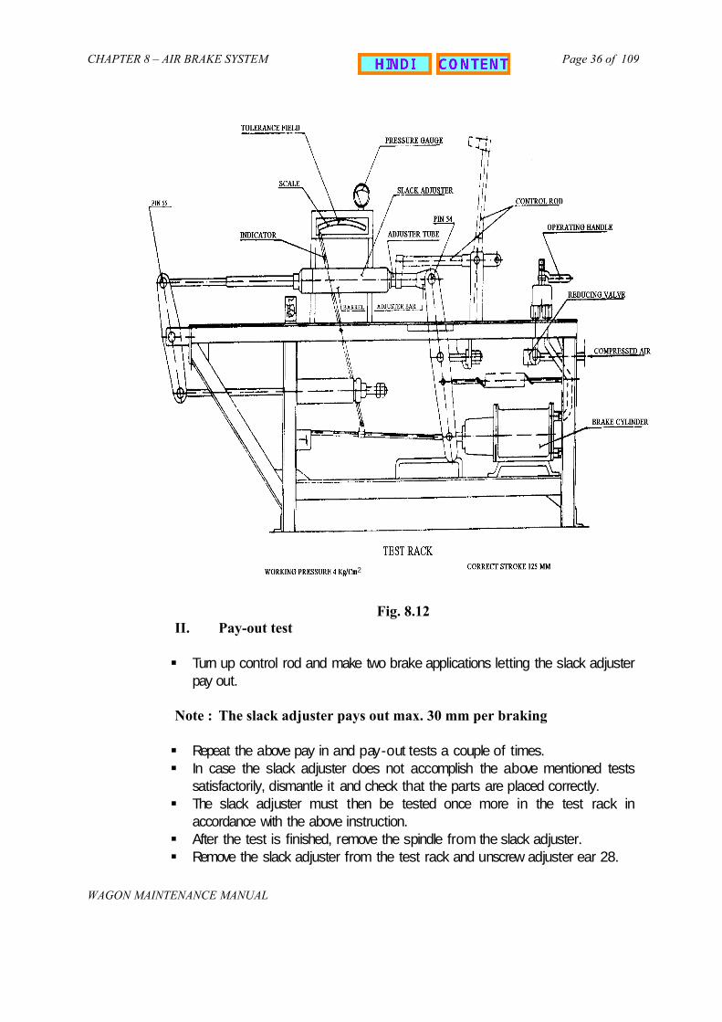
After overhauling, the testing of slack adjuster is carried out in a testrack (Fig. 8.12) for : - i) Take up test & ii) Pay out test
a) Attach the adjuster ear to the free end of the cylinder lever of the test rackb) Screw the test rack spindle into the Slack Adjuster until the entire length of
thread is covered by spindle sleeve and attach the free end of the spindle tothe test rack.
I. Take up or Pay-in test
Let down the control rod, so that the fork of the rod clasps theadjuster tube of the Slack Adjuster
Apply and release the brake a few times letting the slack adjustertake up until the correct piston stroke is obtained (until theindicator is within + 5 mm tolerance field of the scale).
Note: The Slack Adjuster takes up 100 mm per braking.Dimension A1 will be 98 {+1} mm.
{- 4}
CHAPTER 8 – AIR BRAKE SYSTEM
WAGON MAINTENANCE MANUAL
Page 36 of 109
II. Pay-out test
Turn up control rod and makepay out.
Note : The slack adjuster pay
Repeat the above pay in and In case the slack adjuster d
satisfactorily, dismantle it and The slack adjuster must th
accordance with the above ins After the test is finished, rem Remove the slack adjuster fro
2
Fig. 8.12
two brake applications letting the slack adjuster
s out max. 30 mm per braking
pay-out tests a couple of times.oes not accomplish the above mentioned tests check that the parts are placed correctly.en be tested once more in the test rack intruction.
ove the spindle from the slack adjuster.m the test rack and unscrew adjuster ear 28.

CHAPTER 8 – AIR BRAKE SYSTEM
WAGON MAINTENANCE MANUAL
Page 37 of 109
Give adjuster spindle 23 a final thorough inspection making sure that thethreads are liberally greased, and screw it into the Slack Adjuster until its endprotrudes from Adjuster tube 41. Put the safety collar 24 and secure it with thesping dowel sleeve. Make sure that the spring dowel sleeve pin fits tightly andthat its ends do not protrude above the surface of the collar. Should there beany burrs on the collar, smooth off with a fine file an wipe clean. Then screwthe adjuster spindle 23 back into the Slack Adjuster enough to make room forthe adjuster ear 28.
Slide control rod head 26 with control rod 44 on to adjuster tube 41.Place lock washer 27 on threaded portion of adjuster ear 28 and screw ear intothreaded end of adjuster tube 41.
Note : Hold adjuster tube firmly with a pipe wrench. Secure lock washer 27. Install the Slack Adjuster in the brake rigging.
III. Testing of slack adjuster in brake rigging with hand brake
In case a test rack is not available in the work shop, a test of function of theslack adjuster ought to be carried out after the slack adjuster is installed in thebrake rigging and the correct piston stroke is obtained as follows:-
Place an iron object e.g. a hammer between the brake block and the wheeltread. Make two brake applications after the second application the correctpiston stroke should be obtained.
Remove the iron object. Make two brake applications. After the first applicationthe piston stroke is too long, but after the second application the correct pistonstroke is recorded by the slack adjuster.
G. PAINTING
The slack adjuster is given a coat of anticorrosive paint, excluding the adjuster tube 41.
Note : The unthreaded portion of the adjuster spindle 23 should not have a thickcoating.
H. PROCEDURE FOR BRAKE RIGGING SETTING AND MEASUREMENT OF“A” AND “e” DIMENSIONS
The procedure to be adopted for operating brake rigging setting and measuring‘A’ and ‘e’ dimension is listed below:-
(I) For ‘A’ dimension
(i) Ensure the air brake is in fully released condition and all the brake rigging gearsare in proper condition.
(ii) Apply brake three to four times to ease the rigging, by dropping and re-chargingthe air pressure in the brake pipe
(iii) Ensure once again that brake rigging is in fully released condition.

CHAPTER 8 – AIR BRAKE SYSTEM
WAGON MAINTENANCE MANUAL
Page 38 of 109
If ‘A’ dimension is not correct
(iv) Remove pin securing the control rod in U bracket.(v) Detach control rod and rotate it to adjust the gap between barrel end face &
control rod head as specified in note above. Secure the control rod in U bracket.(vi) Apply brakes two to three times.(vii) Check the ‘A’ dimension using the gauge.(viii) Recheck dimension ‘A’ with brakes fully released after every brake release.(ix) Lock the control rod head firmly with check nut and tooth lock washer.(x) Secure pin with split pin.
(II) For ‘e’ dimension
(i) If slack is in excess beyond the capacity of slack adjuster (`e' dimension 575+25mm) there won't be any slack take up provision in the slack adjuster andslack adjuster will only act as strut /pull rod. This is because of brake shoes andwheel wear reaching their condemning limit /near condemning limit. In such casesthe `e' dimension can be restored by adjusting link provided on the bogie framehead stock.
(ii) Measure ‘e’ dimension i.e. distance between protection tube end and mark onadjuster spindle using measuring stick after two or three brake application. Itshould be set to nearly to its maximum limit i.e. 575±25mm.
I. SAFETY PRECAUTIONS
i. Always use wedge between wheel and rail before application and releaseoperations for setting and measuring A and e dimension to prevent rolling ofwagon
ii. Ensure no part of the worker’s body is in touch with moving brake rigging gearsduring application and releasing of brakes.
iii. Do not touch or hold slack adjuster barrel while it is in motion.iv. Before setting any dimension ensure wear of brake shoe does not exceed to its
minimum permissible worn limit (i.e. thickness of the shoe should not be lessthen 20mm).
v. There won't be any slack take up provision in the slack adjuster and slackadjuster will only act as strut /pull rod. This is because of brake shoes and wheelwear reaching their condemning limit /near condemning limit. In such cases thee' dimension can be restored by adjusting link provided on the bogie frame headstock.
vi. Measure ‘e’ dimension i.e. distance between protection tube end and mark onadjuster spindle using measuring stick after two or three brake application. Itshould be set to nearly to its maximum limit i.e. 575±25mm.

CHAPTER 8 – AIR BRAKE SYSTEM
WAGON MAINTENANCE MANUAL
Page 39 of 109
813. DISTRIBUTOR VALVE
Distributor valve is the most important functional component of the air brakesystem and is also sometimes referred to as the heart of the air brake system. Thefunction of the distributor valve is to distribute compressed air received from brake pipeto auxiliary reservoir and control reservoir. In addition to this it also senses drop andrise in brake pipe pressure for brake application and release respectively. It is connectedto brake pipe through branch pipe. Various other components connected to thedistributor valve are auxiliary reservoir, brake cylinders and control reservoir.
MANUFACTURERS OF DISTRIBUTOR VALVE
Three designs of distributor valves are in use on wagons. These are:
i) C3W Type distributor valveii) KE type distributor valve.iii) P4aG type distributor valve.
Various companies presently manufacturing distributor valves are listed below:
Type ManufacturersGreysham and Co. DelhiRailway Product India Ltd. Hosur
C3W Type Distributor Valve.
Stone India Ltd. Calcutta.KE Type Distributor Valve Escorts Ltd. Faridabad
Knorr - Bremse FaridabadM/s. S.D. Technical Services Pvt. Ltd.Delhi.
P4aG Type Distributor Valve
Westing house, Saxby Farmer, Ltd.Calcutta
A decision has already been taken that new wagons manufactured henceforth willonly be fitted either with C3W or KE type distributor valve. Hence the chapter coversdescription and maintenance of these two types of distributor valves only. For repair andmaintenance of P4aG distributor valve, refer to concerned manufacturer’s maintenancemanual.
814. C3W DISTRIBUTOR VALVE
The C3W Distributor Valve (Fig. 8.13) consists of the following main subassemblies:
i. Main bodyii. Quick Service valveiii. Main valveiv. Limiting devicev. Double release v a lvevi. Auxiliary reservoir check valve
CHAPTER 8 – AIR BRAKE SYSTEM
WAGON MAINTENANCE MANUAL
Page 40 of 109
vii. Cut off valveviii. Application chokeix. Release choke.
A. FUNCTION OF DISTRIBUTOR VALVE
For application and release of brakes the brake pipe pressure has to be reducedand increased respectively with the help of driver's brake valve. During these operationsthe distributor valve mainly performs the following function.
(i) Charges the air brake system to regime pressure during normal runningcondition.
(ii) Helps in graduated brake application, when pressure in brake pipe is reduced insteps.
(iii) Helps in graduated brake release, when pressure in brake pipe is increased insteps.
(iv) Quickly propagates reduction of pressure in brake pipe throughout the length ofthe train by arranging additional air pressure reduction locally inside thedistributor valve.
(v) Limits maximum brake cylinder pressure for full service application/ emergencyapplication.
(vi) Controls the time for brake application and brake release depending on serviceconditions
(vii) Facilitates complete discharge of air from the air brake system manually with thehelp of operating lever.
(viii) Protects overcharging of control reservoir when the brake pipe pressure is quicklyincreased for releasing the brakes.
B. WORKING OF C3W DISTRIBUTOR VALVE
The distributor valve distributes the compressed air received from brake pipe tocharge control reservoir through cut off valve and auxiliary reservoir through auxiliaryreservoir check valve. After charging control reservoir and auxiliary reservoir, when brakepipe pressure is reduced by driver's brake valve, pressure differential acts across thelarge diaphragm of hollow stem assembly. As a result, the hollow stem gets lifted,opening the check valve of main valve. This action allows auxiliary reservoir pressure toenter into brake cylinder via limiting device for brake application. Main valve together withthe limiting device limits brake cylinder pressure to rise to a maximum pressure of 3.8 +0.1 Kg/cm2. As the brake cylinder pressure increases it starts acting on top of upperdiaphragm of main valve. This results in downward movement of the main valve alongwith check valve till it reaches lap position. At this stage the check valve of main valvegets closed, stopping further rise of brake cylinder pressure.

CHAPTER 8 – AIR BRAKE SYSTEM
WAGON MAINTENANCE MANUAL
Page 41 of 109
Fig. 8.13 C3W DISTRIBUTOR VALVE

CHAPTER 8 – AIR BRAKE SYSTEM
WAGON MAINTENANCE MANUAL
Page 42 of 109
In this position, no further pressure can enter or exit from the brake cylinder. Everytime brake pipe pressure is reduced gradually in steps, this phenomenon gets repeatedthereby increasing the brake cylinder pressure finally to 3.8 + 0.1 Kg/cm2.
For releasing the brakes, brake pipe pressure is increased by drivers brake valveand the hollow stem assembly of main valve is brought to normal position by neutralizingthe pressure differential across main valve large diaphragm. At this stage hollow stemgives way at its top to exhaust the brake cylinder pressure to atmosphere.
How ever, if brake pipe pressure cannot be increased then for releasing thebrakes the pressure of control reservoir acting on large diaphragm of main valve has tobe reduced. This can be achieved by tilting the release lever of double release valve.Tilting action opens the control reservoir release check valve thereby allowing controlreservoir pressure to vent out & simultaneously hollow stem is pulled down which givespassage to brake cylinder pressure to exhaust to atmosphere resulting in brake release.
C. DESCRIPTION OF VARIOUS COMPONENTS AND SUB-ASSEMBLIES
(a) MAIN VALVE
The main valve is housed in the main body. The various parts alongwith partnumbers (as per manufacturer’s catalogue) are shown in Fig. 8.14.
Fig. 8.14 MAIN VALVE

CHAPTER 8 – AIR BRAKE SYSTEM
WAGON MAIN
Page 43 of 109
the lasubjereserThe tto atconnereferrfunctwhenexhau
(b)
items
TENANCE MANUAL
Fig. 8.15 SECTIONAL VIEW OF MAIN VALVE
The main valve consists of two diaphragms i.e. large and small. The top face ofrge diaphragm, which is situated at the lower position of the stem assembly, is
cted to brake pipe pressure where as the bottom face is subjected to controlvoir pressure. The small diaphragm is situated at the upper position of the stem.op face of small diaphragm is subjected to brake cylinder pressure and bottom facemosphere. At the top of hollow stem the check valve is situated which controlsction of auxiliary reservoir and brake cylinder. The main valve is also some timesed to as three pressure valve. Fig. 8.15 shows various parts of the main valve. Theion of main valve is to supply requisite amount of pressure into the brake cylinder BP pressure is reduced. Also it provides passage for brake cylinder pressure tost to atmosphere, when brake pipe pressure is raised.
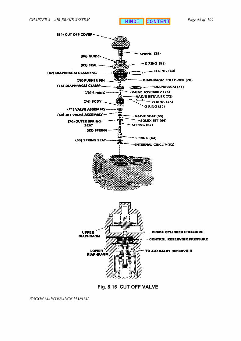
CUT OFF VALVE
The cut off valve is housed in the main body and it consists of the following:
Solex jet Valve retainer. Diaphragm. Diaphragm follower. Internal circlips. Springs. Pusher pin. Jet valve assembly Valve assembly Diaphragm clamp 'O' rings. Body Guides etc.
CHAPTER 8 – AIR BRAKE SYSTEM
WAGON MAINTENANCE MANUAL
Page 44 of 109
Fig. 8.16 CUT OFF VALVE

CHAPTER 8 – AIR BRAKE SYSTEM
WAGON MAINTENANCE MANUAL
Page 45 of 109
The cut off valve has two diaphragms, upper and lower. The top face of lowerdiaphragm is subjected to control reservoir pressure and the bottom face to the brakepipe pressure. The bottom face of upper diaphragm is subjected to brake cylinderpressure, and the top face is subjected to atmosphere and compressed spring pressure.
The cut off valve connects the brake pipe to control reservoir during chargingand cuts off the connection with control reservoir when brake pipe pressure is droppedfor application of brakes. This valve also provides a way to BP pressure from itschamber to auxiliary reservoir check valve.
(c) AUXILIARY RESERVOIR CHECK VALVE
The auxiliary reservoir check valve is housed in the main body. It consists of thefollowing items.
Cap Valve assembly Spring 'O' ring
Fig. 8.17 CHECK VALVE
Auxiliary Reservoir Check Valve helps in charging the auxiliary reservoir. Inaddition to charging it also checks back flow of auxiliary reservoir pressure when brakepipe pressure is dropped for application of brakes.
(d) QUICK SERVICE VALVE
The quick service valve is housed in the main body and consists of the followingitems :
Diaphragm Diaphragm clamp

CHAPTER 8 – AIR BRAKE SYSTEM
WAGO
Page 46 of 109
Retainer Seal Washer 'O' rings Springs Seal Cup Valve assembly Internal circlip Socket etc.
N MAINTENANCE MANUAL
Fig. 8.18 QUICK SERVICE VALVE

CHAPTER 8 – AIR BRAKE SYSTEM
WAGON MAINTENANCE MANUAL
Page 47 of 109
Fig. 8.19 SECTIONAL VIEW OF QUICK SERVICE VALVE
The quick service valve has two diaphragms i.e. upper and lower. The top face ofupper diaphragm is subjected to control reservoir pressure and bottom face to brakepipe pressure. Where as at lower diaphragm, the bottom face is subjected to brake pipepressure when brakes are applied.
The function of quick service valve is to create an initial pressure drop in brakepipe pressure by allowing a sudden entry of brake pipe pressure into the large volumebulb at the start of brake application. This ensures rapid propagation of pressurereduction in brake pipe through out the length of train.
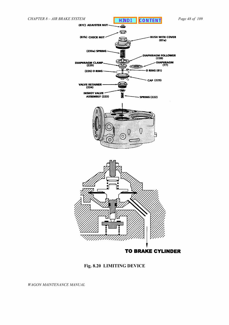
(e) LIMITING DEVICE
The limiting device is housed in the main body and consists of thefollowing items.
Diaphragm. Diaphragm clamp. Diaphragm follower. Cap. Valve retainer. Inshot valve assembly. Adjusting nut. Check Nut. Bush with cover. ‘O’ rings.
CHAPTER 8 – AIR BRAKE SYSTEM
WAGON MAINTENANCE M
Page 48 of 109
ANUAL
Fig. 8.20 LIMITING DEVICE

CHAPTER 8 – AIR BRAKE SYSTEM
WAGON MAINTENANCE MANUAL
Page 49 of 109
The limiting device has one diaphragm. The bottom face of the diaphragm issubjected to brake cylinder pressure during applied brake condition and top face is underpressure of compressed spring and atmosphere.
The function of limiting device is to restrict the maximum brake cylinder pressureto 3.8 + 0.1 Kg/cm2 irrespective of the drop in brake pipe pressure or auxiliary reservoirpressure.
(f) DOUBLE RELEASE VALVE
The double release valve is housed in the bottom cover and it consists of thefollowing items.
Tilt Pin Spring Swivel Rod Spring valve seat Washer Circlip Cap Split pin Choke Control reservoir release check valve Auxiliary reservoir release check valve
Fig. 8.21 DOUBLE RELEASE VALVE

CHAPTER 8 – AIR BRAKE SYSTEM
WAGON MAINTENANCE MANUAL
Page 50 of 109
The function of double release valve is to release the brakes manually when asingle brief pull is given to the lever. However with a continuous pull to the release leverit also vents auxiliary reservoir pressure.
D. DIFFERENT STAGES IN OPERATION OF C3W DISTRIBUTOR VALVE
For effective functioning of the air brake system, the distributor valve has tooperate effectively during :
a) Charging stageb) Application stage andc) Release stage
(a) CHARGING STAGE
During charging stage the compressed air flows from the brake pipe andenters into the brake pipe chamber of the main valve, cut off valve and quickservice valve. Due to this pressure the various valves get activated and performas under.
Main Valve: Due to brake pipe pressure acting on top face of the largediaphragm, differential pressure acts on the main valve. As a result the hollowstem moves downwards there by connecting brake cylinder to atmosphere. Inaddition, because of BP pressure at the top, large diaphragm presses the ringand trigger. This action unlocks the CR release valve by raising the locking rodupwards.
Cut Off Valve: As brake pipe pressure enters into the cut off valve, it flowsthrough the solexjet and valve (which is held open due to action of BP pressureon bottom side of the lower diaphragm) to the control reservoir. As the CR & BPpressure equalises, diaphragm assembly comes down and valve reaches the lapposition. The control reservoir pressure now also reaches the upper portion of topdiaphragm of quick service valve and the bottom portion of large diaphragm ofmain valve.
Simultaneously, the auxiliary reservoir is charged with BP pressurereaching from cut off valve chamber via auxiliary reservoir check valve.
b) APPLICATION STAGE
During emergency application, the brake pipe pressure is reduced rapidlyto 0 kg/cm2 by the driver's brake valve. Because of this drop, the position of thevarious valves will be as described below.
(i) Main valve: With drop in BP pressure to zero, the differential pressure actsacross the large diaphragm. As a result, the hollow stem is moved in upwarddirection and pushes the check valve thereby opening the passage for entry ofauxiliary reservoir pressure at the top portion of main valve. This pressure thengets a way to brake cylinder through limiting device. The brake cylinder thus getscharged with the compressed air. This pressure is known as “BC pressure”.

CHAPTER 8 – AIR BRAKE SYSTEM
WAGON MAINTENANCE MANUAL
Page 51 of 109
(ii) Limiting Device: The auxiliary reservoir pressure which entered into the topposition of main valve now enters the limiting device through the valve which isheld open. From limiting device air pressure now enters the brake cylinder. Whenthe BC pressure rises to 3.8 kg/cm2, the upward force on the diaphragm lifts theguide and the valve at the bottom of the limiting device gets closed. Thus furtherentry of air into the brake cylinder stops.
When the brake cylinder pressure reaches 3.8 kg/cm2, this pressure i.e.BC pressure acts on :
Top face of small diaphragm of main valve Bottom face of upper diaphragm of cut off valve Top (small chamber) of quick service valve
Now because of BC pressure acting at main valve small diaphragm, thehollow stem is pulled down. As a result, the check valve at top comes down to“close” stage and assumes lap position with the hollow stem closing further entryof AR pressure.
(iii)Cut off valve: In cut off valve, the bottom face of the upper diaphragmis subjected to BC pressure. As a result, the guide is lifted. Also the upperportion of lower diaphragm is subjected to CR pressure, which pushes the totalassembly downwards. This action closes the valve of cut off valve, therebyisolating it from control reservoir pressure.
(iv) Quick Service Valve: In quick service valve, BC pressure acts at the topof valve and control reservoir pressure acts at the top face of upper diaphragm.As a result, the stem is pushed down and the valve at the bottom gets opened.Now as the BP pressure inside DV is at zero, the residual BP pressure from thebulb of quick service valve will flow back and vent to the atmosphere.
(v) GRADUATED APPLICATION
During graduated brake application the brake pipe pressure is dropped insteps by driver's brake valve. The movement of various valve assemblies isalmost in the same direction as during emergency application, but theirmovement is comparatively less. In the main valve however after eachapplication the hollow stem assumes the lap position with the check valve.
In addition to this during graduated application the bottom valve oflimiting device is held open to allow compressed air to enter into brake cylinder.
When BC pressure reaches 3.8 kg/cm2 the bottom valve in limiting devicegets closed. Similarly at the time of full service application as the BC pressurereaches 3.8 + 0.1 kg/cm2 within specified time, the position of various valveassemblies will be the same as described above.

CHAPTER 8 – AIR BRAKE SYSTEM
WAGON MAINTENANCE MANUAL
Page 52 of 109
(c) RELEASE STAGE
When the brake pipe pressure is increased in steps for graduated releaseof brakes, the position of the different valves is as described below.
(i) Main valve: At the top face of large diaphragm, as the BP pressureincreases, the hollow stem moves downwards leaving its lap position with thecheck valve. The BC pressure thus finds a passage from top of hollow stem toexhaust to the atmosphere. This action reduces pressure on the top of upperdiaphragm and the hollow stem again lifts up to lap position. It closes the hollowstem top portion. The same cycle is repeated when BP is increased during nextstages. In this way graduated release effect is obtained.
(ii) Cut off valve: As the BP pressure increases the position of cut off valveremains similar as in graduated application i.e. the cut off valve will remainclosed, isolating CR pressure from brake pipe pressure.
(iii) Quick service valve: When the BP pressure is increased, then asexplained above for the main valve, the BC pressure gets exhausted toatmosphere. This action gradually reduces the BC pressure. When BC pressurereduces to 0.8 kg/cm2 during brake release, the force at the top of the quickservice valve becomes comparatively less than BP pressure present in QuickService Valve. As a result, the valve at the top gets lifted thereby giving passageto blocked BP pressure to atmosphere. With the exhaust of BP pressure, theQuick Service Valve of the Distributor Valve again gets ready for next brakeapplication.
(iv) Manual release: Double release valve provides for accelerated manual brakerelease, which is particularly useful during shunting operation. A short pull on thelever of double release valve is all that is needed. This action opens the controlreservoir release check valve, which is then held open by the locking rod. Ventingof control reservoir through the open control reservoir release check valve bringsthe main valve to release position and exhausts the brake cylinder pressurethrough the hollow stem.
E. SPECIFICATION OF C3W DISTRIBUTOR VALVE
The C3W distributor valve is a graduated release type of valve and has beenapproved by UIC to comply with requirement of its specification no. 540 and 547.
F. PERIODIOCITY OF OVERHAULING
The overhauling of the distributor valve is carried out during POH or when thereis some specific problem.
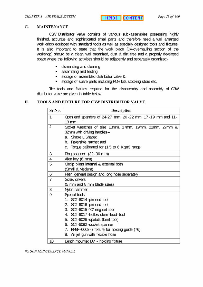
CHAPTER 8 – AIR BRAKE SYSTEM
WAGON MAINTENANCE MANUAL
Page 53 of 109
G. MAINTENANCE
C3W Distributor Valve consists of various sub-assemblies possessing highlyfinished, accurate and sophisticated small parts and therefore need a well arrangedwork-shop equipped with standard tools as well as specially designed tools and fixtures.It is also important to state that the work place (DV-overhauling section of theworkshop) should be a clean, well organized, dust & dirt free and a properly developedspace where the following activities should be adjacently and separately organized:-
dismantling and cleaning assembling and testing storage of assembled distributor valve & storage of spare parts including POH kits stocking store etc.
The tools and fixtures required for the disassembly and assembly of C3Wdistributor valve are given in table below.
H. TOOLS AND FIXTURE FOR C3W DISTRIBUTOR VALVE
Sr.No. Description
1 Open end spanners of 24-27 mm, 20-22 mm, 17-19 mm and 11-13 mm
2 Socket wrenches of size 13mm, 17mm, 19mm, 22mm, 27mm &32mm with driving handles –a. Simple L Shapedb. Reversible ratchet andc. Torque calibrated for (1.5 to 6 Kg.m) range
3 Ring spanner (32-36 mm)4 Allen key (6 mm)5 Circlip pliers internal & external both
(Small & Medium)6 Plier general design and long nose separately7 Screw drivers
(5 mm and 8 mm blade sizes)8 Nylon hammer9 Special tools
1. SCT-6014-pin end tool2. SCT-6016-pin end tool3. SCT-6015-‘O’ ring set tool4. SCT-6017-hollow stem-lead-tool5. SCT-6026-spetula (bent tool)6. SCT-6092-socket spanner7. RPBF-0003-) fixture for holding guide (76)8. Air jet gun with flexible hose
10 Bench mounted DV - holding fixture

CHAPTER 8 – AIR BRAKE SYSTEM
WAGON MAINTENANCE MANUAL
Page 54 of 109
I. OVERHAULING PROCEDURE
Before opening the distributor valve, it needs to be dusted and cleaned externally.The disassembling and assembling of the distributor valve in the workshop is facilitatedby using a bench mounted DV-holding fixture, with facility to rotate through 3600 in thevertical plane and locking it after every 900 rotation.
The distributor valve is mounted on the fixture and can be locked in any desiredposition. The sub assemblies of different valve are dismantled in the sequence. It isimperative that components of each sub assembly have to be carefully handled andarranged in an identifiable group sequence. For part numbers and name of componentsof various sub-assemblies / valves, refer to the concerned manufacturer’s maintenancemanual.
For POH kit, refer RDSO Technical pamphlet No. G-97 Annexure XIII.
815. TESTING OF DISTRIBUTOR VALVE
For the proper functioning of the Air Brake System, it is necessary to test theDistributor Valve. The following tests are carried out to ensure the proper functioning ofDistributor valve:
The following tests are conducted on the distributor valves:
(i) Pressure tightness test – (during charging, application and release test &emergency application test).
(ii) Charging time.(iii) Full service application and release.(iv) Overcharge protection test.(v) CR overcharge reduction test(vi) Emergency application.(vii) Sensitivity test.(viii) Quick service test.(ix) Insensitivity test.(x) Re-feeding test.(xi) Graduated application test.(xii) Graduated release test.(xiii) Quick release test(xiv) Control reservoir check valve reset test.
A. PURPOSE OF CONDUCTING VARIOUS TESTS
a) Pressure Tightness Test
Before conducting any other performance test ( to ensure the efficiency of theDV it is advisable to check for the leakage from any part of the DV). For this purposeBP is charged to regime pressure and then DBV is brought to full application, Emergencyand release positions respectively, and in each of the above positions DV is tested bysoap solution to confirm no leakage. This is done so that every valve of

CHAPTER 8 – AIR BRAKE SYSTEM
WAGON MAINTENANCE MANUAL
Page 55 of 109
DV operates at least once and leakage from every part of the DV is checked. If DV isleakage free then it can be said with high probability that its maintenance or overhauland assembly is carried out properly and generally it should perform as perspecifications in other tests also. However, if other tests are conducted beforeconducting leakage test, and leakage is detected during any test then that leakage is tobe attended and tests are to be repeated. Therefore to avoid reworking it is alwaysadvisable to test the DV first for leakage and once leakage free operation is assuredonly then other tests are to be conducted.
However in KE type of valves, it is possible to test subassemblies of the DV alsobefore finally assembling it. In this type of valve, three main assemblies i.e. R–chargerwith isolating valve, Choke cover & Bottom cover with Quick release valve can be testedfor leakage before fully assembling the DV and the chances of leakage from the DV arethan highly reduced.
b) Charging Time
Charging time for initially charging the control reservoir and auxiliary reservoir upto desired pressure is specified. Operation of the DV should be such that time requiredto charge the CR and AR should neither be more nor less than the specified limits. It isnecessary because if the DV of different wagons operate with different timings, thenbrakes will be applied and released in different wagons with different timings, and thismay create problems.
c) Full Service Application and Release.
For efficient operation of brakes, it is necessary that after operating the DBV forapplying the brakes, brake cylinder pressure should rise to the desired level, very quickly(i.e. from 0 to 3.6 kg/cm2 in 18 to 30 seconds). Therefore all the distributor Valves areto be tested for the time required to raise the brake cylinder pressure. This time shouldneither be more nor less than the specified limits. In this test it is also checked thatbrake should release quickly and it means that brake cylinder pressure should bereleased within specified time period, and hence the DV is tested for release timings also.If the brakes of different wagons operate with different speeds then it can provedisastrous and hence this test ensures that speed of operation of various DV are moreor less same.
d) Overcharge Protection
Sometimes driver overcharges the brake pipe for short duration so that brakepipe is completely charged till last wagon and brakes in every wagon are releasedquickly.
But this overcharging of brake pipe should not result in overcharging of controlreservoir and auxiliary reservoir, because the pressure of control reservoir works asreference pressure for the DV and if the control reservoir is overcharged then it mayresult in malfunctioning of the DV. And hence the DV should be such that it shouldavoid overcharging of CR and AR even if brake pipe is slightly overcharged (In this test,brake pipe is charged up to 6 kg/cm2 for 25 seconds and it is assured that CR and ARshould not get overcharged by 0.1 kg/cm2.)
CHAPTER 8 – AIR BRAKE SYSTEM
WAGON MAINTENANCE MANUAL
Page 56 of 109
e) CR Overcharge Reduction Test
Some times when locomotive connected with a rake is changed, in that casethere may be problems due to different regime pressures of locomotive and rake. Inthese type of cases control reservoir is overcharged for short duration for adjustments,but control reservoir pressure should come back to brake pipe pressure when releasevalve handle of the distributor valve is pulled for 3 seconds.
f) Emergency Application Test
The purpose of this test is similar to that of full application and release test i.e.in this test time taken to raise the brake cylinder pressure during emergency applicationis measured. It is also seen that maximum rise in the brake cylinder pressure is withinlimits.
g) Sensitivity Test
The DV should be sensitive enough to sense the drop in brake pipe pressurequickly and to respond accordingly by raising the brake cylinder pressure so that brakesare applied. Therefore sensitivity test is conducted on DV for checking the fastness ofresponse of DV. In this test it is expected that DV should respond to apply brakes whenBP pressure is reduced by 0.6 kg/cm2 in 6 seconds.
h) Quick Service Test
This test is conducted to ensure proper functioning of quick service valve of C3Wtype DV. While in case of KE type DV it ensures proper functioning of U-controller
i) Insensitivity Test
As explained in the above test, DV should be sensitive enough but at the sametime it should not be very sensitive. Since if it is very sensitive, then it may operate evenwhen there is a small leakage from brake pipe i.e. even when there is a small drop inpressure of the brake pipe. Therefore it is expected that DV should be insensitiveenough so that it does not operate due to small drop in pressure in brake pipe due toleakage. And hence insensitivity test is conducted On DV and it is assured that it shouldnot operate if brake pipe pressure is reducing @ of 0.3 kg/cm2 in 60 seconds.
j) Re-feeding Test
If brakes are in applied position and brake cylinder starts leaking due to someproblem then brake cylinder pressure may drop and it may result in releasing of brakes,which may prove disastrous. Therefore the DV is designed in such a way that itcontinues to supply air to the brake cylinder so that the brake cylinder pressure ismaintained at desired level, even when it is leaking. The re-feeding test assures theproper functioning of main valve in case of C3W type DV and three pressure valve incase of KE type DV.

CHAPTER 8 – AIR BRAKE SYSTEM
WAGON MAINTENANCE MANUAL
Page 57 of 109
k) Graduated Application Test
This test is conducted to prove that brakes can be applied gradually or slowly.This test ensures response of the distributor valve when brake pipe pressure is graduallyreduced i.e. brake cylinder pressure should increase accordingly when brake pipepressure is reduced gradually.
l) Graduated Release Test
Similarly air brake system should be such that brakes can be released graduallyor slowly. To ensure this in this test, brake pipe pressure is increased in steps and it isseen that brake cylinder pressure should reduce accordingly.
m) Quick Release Test
This test is also known as automatic exhausting of brake cylinder. When a wagonis disconnected from the rake, its brake pipe pressure becomes zero. In this condition,brakes of the wagon will be automatically in applied position. To release the brakes amanual handle is provided on the DV. When this handle is pulled, it results in completedraining of AR and CR and brake cylinder, and in other words, the brakes are released.
But at the same time on pulling this lever when brakes are in released position(i.e. when brake pipe is in charged condition) it should not result in releasing of CR &AR. Similarly when brakes are in applied condition and if some one pulls the releaselever even then ideally brake cylinder pressure should not exhaust. But DV design issuch that in this condition brake cylinder pressure exhausts to some extent but it shouldnot exhaust beyond 1 kg/cm2 i.e. even after pulling release lever when brakes are inapplied position, the brake cylinder pressure should not fall below 1 kg/cm2.
This test ensures proper functioning of the DV when release lever is pulled.
n) CR Check Valve Reset Test
This test is also known as “automatic repositioning of quick release system”. Ifbrake pipe pressure is again increased in the above test (CR is in discharged condition)by pulling the release lever in emergency operation or detached wagon condition ( i.e.when brake pipe pressure is zero), double release valve (which is responsible fordischarging the control reservoir) should close automatically so that CR is again charged.
815 B. TOOLS AND EQUIPMENT FOR TESTING
i). Test benchii). Compressed air supply source for supplying air pressure at 7.5 Kg/cm2
iii). Stopwatch – 2 Noiv). Soap water solution

CHAPTER 8 – AIR BRAKE SYSTEM
WAGON MAINTENANCE MANUAL
Page 58 of 109
816. TESTING OF C3W DISTRIBUTOR VALVE
A. DESCRIPTION OF THE TEST BENCH
The schematic diagram of the test bench for C3W valve is shown in the Fig. 8.22.
Fig. 8.22TEST RACK FOR C3W DISTRIBUTOR VALVE
P1 – Pressure in feed pipe (not applicable in single pipe) P2 – Input pr. regulated at 5 Kg/cm2 in the brake pipeline. P3 – Brake pipe reservoir pressure. P4 – Pressure in the Control Reservoir (CR) P5 – Pressure in the brake cylinder. P6 – Pressure in the auxiliary reservoir.
Isolating cocks as given below –
V1 – for isolating the supply of air to the auxiliary reservoir at 6 Kg/Cm2 (i.e.to test the system in single pipe).
V2 – To connect/isolate BP pressure. V3 – for controlling the supply of air to the brake pipe at 5 kg/cm2. V4 – for exhausting the brake pipe pressure. V5 – for exhausting the brake cylinder pressure. V6 – It is an isolating cock with a choke for releasing the brake pipe pressure
at a desired rate for sensitivity test and for graduated application test. V7 – It is a isolating cock with a choke for releasing the brake pipe pressure at
a desired rate for insensitivity test V8 – For controlling air pressure in the brake pipe with the help of the drivers
brake valve. V9 – Isolating cock with a choke for increasing the brake pipe pressure in the
desired steps for graduated release test and for CR check valve reset test.

CHAPTER 8 – AIR BRAKE SYSTEM
WAGON MAINTENANCE MANUAL
Page 59 of 109
The test bench consists of the following components :
(i) Source of compressed air supply at 7.5 kg/cm2
(ii) Pressure regulator R1 - to supply air at 6 kg/cm2.(iii) Pressure Regulator R2 - to supply air at 5 kg/cm2
(iv) Brake cylinders – 2 No. i.e. BC (1) and BC (2)(v) Auxiliary reservoir AR (1) and AR (2) each having a capacity to store 100
litre of air at 6 kg/cm2.(vi) Brake pipe pressure reservoir having a capacity to store 18 litres of air
at 5 kg/cm2.(vii) Control reservoir cylinder having a capacity to store 6 litres of air at 5
kg/cm2.(viii) Automatic brake valve (A9), which is used as the drivers brake valve in
the locomotive along with the C2 relay valve. This is supplied compressedair at 6 Kg/cm2. With the help of the A9 valve, the pressure in the brakepipe can be increased or decreased.
(ix) Six Pressure Gauges to indicate pressures at different locations.
B. PREPARATION OF TEST BENCH
Preparation of the test bench requires the following steps –
Setting of the pressure regulators and the brake valve Leakage testing of automatic pipe network Calibration of chokes
C. SETTING OF THE REGULATOR AND AUTOMATIC BRAKE VALVE
(i) Block C3W distributor connections by putting blanking gasket in betweenthe distributor and its pipe bracket.
(ii) Close all isolating cocks (i.e. V1 to V9).(iii) Supply compressed air at 7.5 kg/cm2 at the test rack intake.(iv) Adjust the regulators R1 and R2 so that the pressure gauges P1 and P2
indicate the pressure as 6 kg/cm2 and 5 kg/cm2 respectively(v) Open isolating cock V3 and note that both the gauges P3 (i.e. Brake pipe
reservoir pressure) and P2 (brake pipe pressure ) show 5 kg/cm2
(vi) Close isolating cock V3 and open cock V4 to vent out BP. reservoirpressure. Gauge P3 will indicate zero pressure in this condition
(vii) Adjust drivers brake valve A9 at 5 Kg/cm2, check this adjustment byopening isolating cock V8. This will increase BP reservoir pressure to 5Kg/cm2 and this can be checked by gauge P3.
(viii) Close the cock V8

CHAPTER 8 – AIR BRAKE SYSTEM
WAGON MAINTENANCE MANUAL
Page 60 of 109
D. LEAKAGE TESTING OF PIPE NETWORK Open isolating cock V1 to charge the auxiliary reservoir to 6 kg/cm2
Check this pressure from the pressure gauge P6 Open isolating cock V2 to overcharge the brake pipe pressure to 6
kg/cm2. Check this pressure from the pressure gauge P3 When pressure in the pressure gauges P6 and P3 are stabilised at 6
kg/cm2 then close isolating cocks V1 and V2. Wait for one minute forstabilising of pressure in gauges P3 and P6.
Leakage must not exceed 0.1 kg/cm2 in one minute as shown by thesegauges
If there is any leakage. Identify its location with the help of soapsolution and arrest the leakage before proceeding further.
E. TEST PROCEDURETests are conducted in a particular sequence for reducing the time
required in opening and closing of various valves. In the test bench describedabove, following test sequence is optimum as far as the time required in testingdistributor valves are concerned. In any other type of test bench arrangement,some other test sequence may be optimum. The valve V1 is kept closed duringtesting.Note : Although pressure tightness test is supposed to be conducted in the
beginning for every position of the distributor valve. But in thisarrangement of test bench, it is convenient to conduct chargingtime test before pressure tightness test.
(I). Charging time of auxiliary reservoir and control reservoir.
a) Close all the isolating cocks.b) Set air pressure regulator R1 and R2 at 6 and 5 Kg/cm2 respectively.c) Check pressure in the pipe by P1 and P2. It should be 6 and 5 Kg/cm2
respectively. If required, adjust the pressure regulator R1 and R2 to achievethese pressures.
d) Open isolating cock V3 and with the help of a stopwatch, note time taken bygauge P4 (CR) and P6 (AR) to rise from 0 to 4.8 Kg/cm2. Two separatestopwatches will be required. It is better if two persons monitor thesepressures separately.
e) For control reservoir, the charging time should be 260±20 seconds and forauxiliary reservoir it should be 270±30 seconds.
(II). Pressure tightness testa) Apply soap water all over C3W valve. No leakage is permissible.b) Close isolating cock V3 after pressure gauges. P3 (Brake pipe), P4
(Control reservoir) and P6 (Auxiliary reservoir) indicates 5 Kg/cm2. Waittill reading in gauges settle.
c) Switch on a stopwatch and monitor pressure in these gauges. Thereshould be no drop in pressure in one minute duration.

CHAPTER 8 – AIR BRAKE SYSTEM
WAGON MAINTENANCE MANUAL
Page 61 of 109
(III). Full service application and release test.
a) Automatic brake valve should be set at 5 Kg/cm2 (as done during settingof the test bench). Bring handle in release position.
b) Open isolating cock (V8) and note gauges P4 (CR) and P6 (AR) showsexactly 5Kg/cm2.
c) Move A9 handle to service application position, so that P3 (Brake pipepressure) falls from 5 to 3.4 Kg/cm2.
d) Switch on the stopwatch as soon as the handle of A9 is moved to serviceapplication position in the above step and note the time taken by brakecylinder pressure (P5) to rise from 0 to 3.6 Kg/cm2. This time should be18 to 30 seconds.
e) Wait for brake cylinder pressure (P5) to settle and note the maximumpressure to which it reaches. The maximum pressure should be 3.8±0.1Kg/cm2.
f) Move A9 handle to release position and switch on the stopwatchimmediately to note the time taken by brake cylinder pressure (P5) to fallfrom 3.8 to 0.4 Kg/cm2. This time should be within 15 to 20 seconds.
(IV). Overcharge protection test
a) When A9 handle is in release position, brake pipe, auxiliary reservoir andcontrol reservoir pressures i.e. pressures in gauges P3, P4 and P6 shouldbe at 5 Kg/cm2.
b) Move A9 handle to emergency position. In this case brake pipe pressure(as per gauge P3) will fall to zero and brake cylinder pressure (as perP5) will reach to its maximum value.
c) Close isolating cock V8 and move A9 handle to release position. In thisposition brake pipe pressure (P3) will again rise to 5 Kg/cm2 and brakecylinder pressure (P5) will fall to zero, while auxiliary reservoir pressure(P6) and control reservoir pressure (P4) will be around 5 Kg/cm2.
d) Open isolating cock V2 and overcharge brake pipe to 6 Kg/cm2 for 25seconds (see it in gauge P3) and then immediately close isolating cockV2 and open cock V8. But during this, control reservoir should not beovercharged by 0.1 Kg/cm2 over regime pressure of 5 Kg/cm2 (as seenby gauge P4).
(V). CR over charge reduction test
a) Allow over charging of CR and AR at 5.7 Kg/cm2 and bring back BPpressure to 5 Kg/cm2 by closing the isolating cock V2 and V1.
b) Pull the double release lever of DV for 3 seconds and note down the fallin pressure of control reservoir.
c) The control reservoir pressure should return back to brake pipe pressurei.e. 5 Kg/cm2 as seen by P3.

CHAPTER 8 – AIR BRAKE SYSTEM
WAGON MAINTENANCE MANUAL
Page 62 of 109
(VI). Emergency application testa) With brake pipe, control reservoir and auxiliary reservoir (i.e. P3, P4 and
P6) charged to 5 Kg/cm2. Move A9 handle to emergency applicationposition.
b) As soon as handle is moved to emergency application position, switch onthe stopwatch and note down the time taken by the brake cylinderpressure (P5) to rise from 0 to 3.6 Kg/cm2. This time should be between3 to 5 seconds.
c) Also note the maximum pressure to which brake cylinder is charged. Thispressure should be 3.8±0.1 Kg/cm2.
(VII). Sensitivity test
a) Move A9 handle to release position to recharge the brake pipe pressure(P3) to 5 Kg/cm2.
b) Close isolating cock V8.c) Open isolating cock V6. Switch on the stopwatch as soon as isolating
cock V6 is opened and note the time taken by brake pipe pressure todrop by 0.6 Kg/cm2. This time should be 6 seconds.
d) Brake cylinder pressure (P5) should start rising within 1 second andwithin 6 seconds piston should start moving for application of brakes.
(VIII). Quick service test
Close isolating cock V6 and immediately observe the applied brakes, theyshould remain applied.
(IX). Insensitivity test
a) Open isolating cock V3 to recharge BP, CR and AR to 5 Kg/cm2 (asseen by P3, P4 and P6).
b) Close isolating cock V3 and open isolating cock V7.c) As soon as isolating cock V7 is opened, start stopwatch and check that
BP pressure (P3) drops by 0.3 Kg/cm2 in 60 seconds.d) There should not be any rise in brake cylinder pressure and brake
cylinder piston should not start moving i.e. brakes should not apply.
(X) Re-feeding test
a) Close isolating cock V7 and open V3 to recharge brake pipe, controlreservoir and auxiliary reservoir to 5 Kg/cm2 (As seen by P3, P4 and P6respectively).
b) Bring A-9 valve handle to full service application position. BC pressurewill become 3.8±0.1 Kg/cm2 (as seen by P5).
c) Exhaust the brake cylinder by slightly opening the isolating cock no V5.d) Observe brake cylinder pressure in the gauge no. P5. It should not
become zero and should stabilize at some particular value (since re-feeding to brake cylinder is available via distributor valve).

CHAPTER 8 – AIR BRAKE SYSTEM
WAGON MAINTENANCE MANUAL
Page 63 of 109
e) Fall in brake cylinder pressure should not be more than 0.15 Kg/cm2
from 3.8±0.1 Kg/cm2 (i.e. it should not fall below 3.65±0.1 Kg/cm2).f) Close exhaust cock no. V5.
(XI). Graduated application test
a) See that brake pipe, control reservoir and auxiliary reservoir are at 5Kg/cm2 (as seen by P3, P4 and P6 respectively).
b) Close isolating cock V3.c) Decrease P3 (BP) pressure in steps of 0.2 Kg/cm2 (min 7 steps) by
slowly opening and closing cock V6 i.e. starting from 4.6 Kg/cm2 andthen to 4.4, 4.2, 4.0, 3.8, 3.6 and 3.4 Kg/cm2.
d) Note down the corresponding increase in brake cylinder pressure (P5).e) Also note the brake pipe pressure (P3) at maximum brake cylinder
pressure (P5). This BP pressure (P3) should be 3.4 to 3.7 Kg/cm2.
(XII). Graduated release test
a) Close isolating cock V6.b) Increase brake pipe pressure (P3) in steps of 0.2 Kg/cm2 by opening and
closing cock V9. The Brake pipe pressure will rise from 3.6 to 3.8Kg/cm2.
c) Note corresponding decrease in the brake cylinder pressure (P5).d) Also note the maximum pressure of brake pipe (P3) at which brake
cylinder pressure (P5) is exhausted completely. This pressure should be4.85 Kg/cm2.
(XIII). Quick release test
a) Close isolating cock V9.b) Open isolating cock V3 to charge brake pipe, auxiliary reservoir and
control reservoir pressure (P3, P4 and P6) to 5 Kg/cm2. Close isolatingcock V3 when pressure in P3, P4 and P6 stabilizes.
c) Open isolating cock V4 for emergency application and see that. Brakecylinder (P5) is charged to 3.8 Kg/cm2.
d) Make a short pull on the release valve handle. As soon as this handle ispulled, control reservoir (P4) and brake cylinder (P5) should becompletely vented.
e) Close cock V4.
(XIV). CR check valve reset test
a) Continue to pull the release valve handle of the distributor valve tocompletely vent out auxiliary reservoir (P6).
b) Recharge by opening cock V9.c) Control reservoir (gauge P4) should be isolated from the atmosphere
when brake pipe (gauge P3) pressure exceeds 0.2 Kg/cm2.

CHAPTER 8 – AIR BRAKE SYSTEM
WAGON MAINTENANCE MANUAL
Page 64 of 109
817. KE DISTRIBUTOR VALVEThese valves are also referred as KEO and KEGiSL in some publications. The KE
distributor valve consists of the following main subassemblies:
(a). Three pressure valve e) Minimum pressure limiter(b). U controller f) Maximum pressure limiter(c). R charger g) A controller(d). Choke cover h) Quick release valve
Fig. 8.23 KE DISTRIBUTOR VALVE

CHAPTER 8 – AIR BRAKE SYSTEM
WAGON MAINTENANCE MANUAL
Page 65 of 109
A. DESCRIPTION OF VARIOUS SUBASSEMBLIES OF KEGiSL DISTRIBUTOR VALVE
(a) THREE PRESSURE VALVE
Fig. 8.24 THREE PRESSURE VALVE
The three pressure valve is housed in the vertical central bore between the topand bottom face. The function of the three pressure valve is to control charging anddischarging of the brake cylinder in accordance with the change in the brake pipepressure. The three pressure valve responds to the slightest variation of brake pipepressure. The U controller, R charger and choke cover are housed on one face of thedistributor valve.

CHAPTER 8 – AIR BRAKE SYSTEM
WAGON MAINTE
Page 66 of 109
(b) U-CONTROLLER
Tof C3W applicatioduring insimultan
( c) ‘
N
Fig. 8.25 U CONTROLLER
he function of the ‘U’ controller is similar to the function of quick service valveDistributor Valve. The U-controller gets activated during start of the braken and taps off a small amount of brake pipe pressure from Distributor Valveitial brake application. This action increases initial pressure reduction & causes
eous rapid propagation of braking impulse throughout the length of the train.
R’ CHARGER
ANCE MANUAL
Fig. 8.26 R-CHARGER

CHAPTER 8 – AIR BRAKE SYSTEM
WAGON MAINTENANCE MANUAL
Page 67 of 109
The function of the 'R' charger is to supply compressed air from the brake pipeto the auxiliary reservoir 'R' charger also separate the auxiliary reservoir from the brakepipe through check valve (which is located inside 'R' charger) when BP pressure is lessthan AR pressure.
(d) CHOKE COVER
The choke cover has application & release chokes inside it. The application andrelease chokes help in regulating the application and release times of brake.
Fig. 8.27 CHOKE COVER
On the face opposite to face 'A' are housed, maximum pressure limiter, minimumpressure limiter and 'A' controller.
(e) MINIMUM PRESSURE LIMITER
Fig. 8.28 MINIMUM PRESSURE LIMITER

CHAPTER 8 – AIR BRAKE SYSTEM
WAGON MAINTENANCE MANUAL
Page 68 of 109
The minimum pressure limiter gets activated during initiation of brake application.The minimum pressure limiter helps in rapid charging of brake cylinder upto adetermined pressure to overcome rigging resistance.
(f) MAXIMUM PRESSURE LIMITER
Fig. 8.29 MAXIMUM PRESSURE LIMITER
The function of maximum pressure limiter is similar to the limiting device in theC3W Distributor valve. The maximum pressure limiter limits the maximum brake cylinderpressure to 3.8 + 0.1 kg/cm2 irrespective of the auxiliary reservoir pressure.
(g) 'A' CONTROLLER
The function of 'A' controller is similar to that of cut off valve of the C3WDistributor Valve.
Besides charging control reservoir during charging operation 'A' controller isolatescontrol reservoir pressure when brakes are applied. 'A' controller also protects controlreservoir from overcharging.

CHAPTER 8 – AIR BRAKE SYSTEM
WAGON MAINTENANCE MANUAL
Page 69 of 109
Fig. 8.30 A-CONTROLLER
(h) QUICK RELEASE VALVE
The quick release valve allows the brakes of the wagons to be fully released bymeans of manually pulling of handle.For effective functioning of the air brake system, the KEGisl distributor valve has tooperate effectively during :
Charging stage
Application stage and
Release stage

CHAPTER 8 – AIR BRAKE SYSTEM
WAGON MAINTENANCE MANUAL
Page 70 of 109
Fig. 8.31 QUICK RELEASE VALVE

CHAPTER 8 – AIR BRAKE SYSTEM
WAGON MAINTENANCE MANUAL
Page 71 of 109
817 B. FUNCTIONING OF KE DISTRIBUTOR VALVE.
(a) CHARGING STAGE
During this stage, the compressed air flows from the driver's brake valveinto the brake pipe which charges the control reservoir, bottom cover chamberand auxiliary reservoir. During charging stage, the path followed by compressedair is as follows.
(i) Charging of control reservoir
During charging, the compressed air flows from brake pipe, dirt collector,isolating valve and through choke to brake pipe chamber above the large pistonand to the 'A' controller. Due to brake pipe pressure acting on top of the largepiston, the three pressure valve is pushed down and the port gets closed by thelarge diaphragm.
Air also flows to the 'A' controller through choke. It passes throughsensitivity port, and from there to the bottom cover chamber through port. Fromthe bottom cover chamber, the air enters the control reservoir. When the BPpressure above the large diaphragm gets equal to control reservoir pressure (atbottom cover chamber), the large piston diaphragm gets lifted up and opens theport.
(ii) Charging of Auxiliary Reservoir
For charging the auxiliary reservoir, air from BP passes from dirtcollector to the 'R' charger via the isolating valve. Air entering the 'R' chargerpasses through the intermediate piece and opens the sealing flap. Therefrom, airenters the auxiliary reservoir and charges it to 5kg/cm2.
(b) APPLICATION STAGE
The application of brakes can either be emergency, full service orgraduated.
(i) Emergency application:
When the brake pipe pressure is reduced from 5kg/cm2 to zero thepassage from auxiliary reservoir to the brake pipe is closed by the sealing flap inthe 'R' charger, because of differential pressure acting on either side of thesealing flap. At the same time pressure differential acts across the largediaphragm of the three pressure valve which pushes the piston unit (large &small) upwards. The upward movement of the piston unit closes the outlet portby uplifting of the control sleeve.
In addition to this, the outlet port at the top of the three pressure valvecloses and the inlet port opens. The air from auxiliary reservoir through theminimum pressure limiter, the maximum pressure limiter and the choke, entersthe top of the three pressure valve and through the open inlet port, the airenters into the brake cylinder.
CHAPTER 8 – AIR BRAKE SYSTEM
WAGON MAINTENANCE MANUAL
Page 72 of 109
When the pressure in the brake cylinder reaches 0.8 kg/cm2, firstminimum pressure limiter gets closed and there after maximum pressure limitergets closed when the pressure in the brake cylinder reaches 3.8 kg/cm2. With therise in BC pressure the 'A' controller gets closed, maintaining the pressure in thecontrol reservoir.
During full brake application, the brakes are applied at slower rate than inemergency application. BP pressure to be reduced by 1.5 kg/cm2 instead of 5kg/cm2.
Note: At the beginning i.e. when BP pressure is reduced and control sleeve lifts outletport of BP, air from top of the control sleeve reaches U-chamber that is alreadyopen to atmosphere and some BP air thus vents off. This causes a sudden extradrop in the remaining BP pressure inside the DV and accelerates the effect ofbrake application, propagating this action throughout the length of the train.
By this action brake cylinder pressure starts rising. The brake cylinderpressure also acts on diaphragm at U-controller, A controller, Minimum Pressurelimiter and maximum pressure limiter. As BC start to rise the A controller valve isclosed isolating BP and CR. Also the U controller is closed and local reduction ofBP is stopped. As BC reaches 0.8 kg, it closes the minimum pressure limiter andnow the rising BC pressure can pass through maximum limiter through chokewhich regulates the rate of BC rising. As BC reaches 3.8+0.1 kg per sq. cm.,maximum pressure limiter also closes and no further rise of BC is possible. Thisrise of BC to 3.8+ .1 kg per sq. cm. comes to effect at BP pressure dropping to1.5 kg/sq. cm.
(ii) Graduated application
When the brake pipe pressure is reduced in steps for graduatedapplication of brakes, the increase in brake cylinder pressure is at a controlledrate and in proportion to brake pipe pressure reduction.
As soon as the brake cylinder pressure rises in proportion to brake pipepressure reduction, it causes the piston unit (large & small) to move down intolap position thereby closing the top inlet port without opening the top outlet port.Thus feeding of air from the auxiliary reservoir to the brake cylinder is cut off.This cycle is repeated every time BP is reduced in steps effecting graduatedapplication of brakes.
(c) RELEASE STAGE
For releasing the brakes, the pressure in the brake pipe is increased andthe pressure above the large piston increases. Thus the differential pressureacross the large piston reduces. As a result, the piston unit (large & small)moves down thereby opening the top outlet port and closing the top inlet port.The brake cylinder pressure thus passes through the outlet port and getsexhausted to atmosphere through the release choke. As the BP pressure reaches4.85 kg/cm2, the brake cylinder is almost completely drained and the threepressure assembly attains its charging/running position again.
CHAPTER 8 – AIR BRAKE SYSTEM
WAGON MAINTENANCE MANUAL
Page 73 of 109
(i) Graduated release
If the pressure in the brake pipe is increased in steps, the releasingprocedure starts as before. However the top outlet port get closed and come tolap position as soon as piston unit (large & small) moves up due to fall of brakecylinder pressure.
ii) Manual Release
Sometimes manual release of brakes is very helpful and thus provision ismade in the distributor valve for manually releasing the brakes. When a short pullis given to pulling lever, it tilts the pressure piece. As a result, the pressure rodand pin are pushed upwards against force of spring. The air thus flows fromcontrol reservoir and passes through port and then from narrow passage toatmosphere. This will continue until the brake pipe pressure acting on large pistonmoves the supporting plate down. This results in downward movement of the pinthereby closing the passage of air to exhaust.
If however, there is no more pressure in brake pipe (i.e. after emergencyapplication), when short pull is given to release handle then pressure piece istilted & pin remains in top position. As a result control reservoir pressure iscompletely exhausted. The tilted pressure piece is then immediately restored toits initial position by spring. The brake cylinder pressure starts exhausting aftercontrol reservoir is exhausted upto 1.2 kg/cm2. and then simultaneously both getexhausted completely.
During refilling, the pressure in brake pipe rises more rapidly via chokeand port so that the large piston immediately moves down causing the pin tomove to lap position.
817 C. SPECIFICATION OF KE DISTRIBUTOR VALVE
KE distributor valve is a graduated release type of valve and has been approvedby UIC to comply with requirement of its specification no. 540 and 547.
818. TESTING OF KE TYPE DISTRIBUTOR VALVE
Schematic diagram of the test bench for KE valve is shown in Fig. 8.32. Testbench consists of the following components:-
(i). Source of compressed air supply at 7.5 Kg/cm2.(ii). Pressure regulator (Item no. 4) : to supply air at 6.5 Kg/cm2.(iii). Pressure regulator (Item no. 24): to supply air at 6 Kg/cm2.(iv). Brake cylinders (Item no. 17) : two numbers(v). Auxiliary reservoir [Item no 21(A) and 21(B)] each having capacity to store 100
liters of air at 6 Kg/cm2.(vi). Brake pipe reservoir (item no. 9) having capacity to store 60 liters of air at 6
Kg/cm2.

CHAPTER 8 – AIR BRAKE SYSTEM
WAGON MAINTENANCE MANUAL
Page 74 of 109
(vii). Equalizer reservoir (Item no. 7) to store air at 6 Kg/cm2 pressure. This reservoirsupplies air to drivers brake valve whenever it is needed by DBV due to loss ofair.
(viii). Drivers brake valve (item no. 6). It is same as provided in the locomotive. Itspurpose is to control the brake pipe pressure.
(ix). Item no. 2 : Filter in supply to filter out any oil, grease etc.
(x). Item no. 22 : Auxiliary reservoir check valve. This prevents back flow of air i.e.flow of air from auxiliary reservoir to supply.
(xi). Item no. 5 : Main reservoir to store 60, liters of air at 6.5 Kg/cm2.
(xii). Item no. 14 : Common pipe bracket, KE type distributor valve which is under testis to be mounted on this.
(xiii). Five pressure gauges to indicate the pressure in different locations as givenbelow –
Item no. 25 : Main reservoir pressure.Item no. 26 : Brake pipe pressureItem no. 27 : Control reservoir pressureItem no. 28 : Auxiliary reservoir pressureItem no. 29 : Brake cylinder pressure.

CHAPTER 8 – AIR BRAKE SYSTEM
WAGON MAINTENANCE MANUAL
Page 75 of 109
Fig. 8.32 TEST BENCH FOR KE DISTRIBUTOR VALVE
(xiv). Isolating cocks as given below-
Item no. 1: Supply of compressed air to main reservoir. Item no. 3 : For exhausting main reservoir pressure. Item no. 8 : For controlling air pressure in brake pipe with the help of
drivers brake valve. Item no. 10 : For isolating common pipe bracket from the brake pipe
reservoir. Item no. 11 : For exhausting brake pipe pressure. Item no. 12 : It is with a choke for releasing brake pipe pressure at a
desired rate for insensitivity test.

CHAPTER 8 – AIR BRAKE SYSTEM
WAGON MAINTENANCE MANUAL
Page 76 of 109
Item no. 13 : It is with a choke for releasing brake pipe pressure forsensitivity test.
Item no. 15 : Provided between brake pipe line and control reservoir.Normally it is kept closed and is used only for quick charging (or directcharging) of the control reservoir.
Item no. 16 : Isolating cock with a choke for exhausting brake cylinderpressure at a desired rate.
Item no. 19 : For isolating auxiliary reservoir from common pipe bracket. Item no. 20 : Provided between brake pipe and auxiliary reservoir for direct
charging of brake pipe (I.e. by bypassing the driver’s brake valve). Item no. 23 : It is the cock which connects the auxiliary reservoir with feed
pipe in twin pipe system. This valve is kept closed in single pipe operation. Item no. 30 : For exhausting auxiliary reservoir.
A. TEST PROCEDURE
Tests are conducted in a particular sequence for reducing time requiredin opening and closing of various valves. In the test bench described above,following test sequence is optimum as far as time required in testing thedistributor valves are concerned. In any other type of test bench arrangement,some other test sequence may be optimum. The isolating cock 23 is kept closedduring testing.
(i) Pressure tightness test
a) In case of the KE type distributor valve, subassemblies are tested for leakageetc. during overhauling. This is done in order to detect defects early, if any,and to save the time. Normally three main subassemblies are tested forleakage i.e. R-charger with isolating valve, choke cover and bottom cover.
Since subassemblies are tested in advance for leakage, it is notnecessary to test distributor valve for leakage in the beginning. Instead leakagetest in different positions of the DV is carried out during conduction of testrelated to the concerned positions and hence the leakage test is conductedduring following tests :
(i). Charging time(ii). Full service application and release(iii). Emergency application and release
(ii) Charging time of auxiliary reservoir and control reservoir
a) Mount the distributor valve under test on the bracket of the test benchb) Close all the isolating cocks of the test benchc) Set the air pressure regulators R1 and R2 at 6.0 and 6.5 Kg/cm2
respectively

CHAPTER 8 – AIR BRAKE SYSTEM
WAGON MAINTENANCE MANUAL
Page 77 of 109
d) Open isolating cock (1)e) Opening of isolating cock (1) will supply compressed air at 7.5 to 8
Kg/cm2
f) Adjust pressure regulator (4). So that main reservoir is filled and itspressure as indicated by gauge no. 25 becomes 6.5 Kg/cm2
g) Air at this pressure i.e. 6.5 Kg/cm2 will be available at drivers brake valveh) Bring drivers brake valve in release and running position. This will supply
air to brake pipe at 5 Kg/cm2
i) Open isolating cock (8), this will supply air at 5 Kg/cm2 to brake pipej) Open isolating cock (10), this will supply air at 5 Kg/cm2 to distributor
valvek) Open isolating cock (19). This will connect the auxiliary reservoir (i.e. 21A
& 21B) to the DVl) See that pressure in main reservoir (gauge no. 25) is 6.5 Kg/cm2, in
brake pipe, (gauge no. 26) and control reservoir (gauge no. 27) is 5Kg/cm2. If not, adjust with the help of pressure regulator (4)
m) Bring handle of R charger in off positionn) Exhaust auxiliary reservoir pressure by opening isolating cock (30). It will
be indicated by gauge no. 28 and control reservoir by pulling quickrelease lever of the bottom cover. It will be indicated by gauge no. 27.Close cock (30)
o) But in the above step, MR and BP pressure should not drop below 6.5Kg/cm2 and 5 Kg/cm2 respectively as shown by gauge no. (25) and (26)
p) Bring the handle of the R-charger in on position and simultaneouslyswitch on the stop watches to measure the charging time of auxiliaryreservoir and control reservoir. Two separate stopwatches will be required,it is better if two persons monitor these pressures respectively
q) Note time taken by gauges (28) and (27) to rise from 0 to 4.8 Kg/cm2.r) Apply soap solution all over the body of DV, no leakage should be
observed(iii) Full service application and release
a) Bring driver’s brake valve in full service application position, so that brakepipe pressure (gauge no. 26) falls from 5 to 3.4 Kg/cm2.
b) Switch on the stop watch as soon as the handle of drivers brake valve isbrought to full service application position in the above step and note thetime taken by brake cylinder pressure (gauge no. 29) to rise from 0 to3.6 Kg/cm2. This time should be 18 to 30 seconds.
c) Wait for brake cylinder pressure (gauge no. 29) to settle and note themaximum pressure to which it reaches. The maximum pressure should bewithin 3.8±0.1 Kg/cm2.

CHAPTER 8 – AIR BRAKE SYSTEM
WAGON MAINTENANCE MANUAL
Page 78 of 109
d) Bring DBV in release position and switch on the stop watchsimultaneously to note the time taken by brake cylinder pressure(gauge no. 29) to fall from 3.8 to 0.4 Kg/cm2. This time should bewithin 45 to 60 seconds.
e) Apply soap solution all over the body of DV, no leakage should beobserved.
(iv) Overcharge protection test
a) When DBV is in release position, ensure that brake pipe pressure(gauge no. 26) and control reservoir pressure (gauge no. 27) is at 5Kg/cm2 and brake cylinder (gauge no. 29) is at 0 Kg/cm2.
b) Open isolating cock (23). In this condition auxiliary reservoir will getsupply at 6 Kg/cm2. Adjust pressure regulator no. 24 to see thatpressure indicated by gauge 28 is 6 Kg/cm2.
c) Now operate driver’s brake valve to emergency application position. Inthis case, brake pipe pressure (gauge no. 26) will become zero andbrake cylinder pressure (gauge no. 29) will rise to its maximum valuei.e. 3.8±0.1 Kg/cm2.
d) Isolate DBV from the brake pipe by closing cock no. 8 and then bringDBV handle to release position.
e) Open isolating cock no. 20 to connect (via auxiliary reservoir) tobrake pipe to bring brake pipe pressure at 6 Kg/cm2 as seen bygauge no. 26. Maintain this position for 25 seconds.
f) Close isolating cock no. 20 and open isolating cock no. 8, this willbring brake pipe pressure to 5 Kg/cm2 again.
g) Now observe rise in control reservoir pressure as seen by gauge no.27. It should not go beyond 5.1 Kg/cm2 i.e. CR should not beovercharged by 0.1 Kg/cm2 over stipulated pressure of 5 Kg/cm2.
(v) CR Overcharge reduction testa) Open isolating cock no. 15 and 20, allow overcharging of control
reservoir and auxiliary reservoir at 5.7 Kg/cm2 by using isolating cockno. 23.
b) Bring back brake pipe pressure to 5 Kg/cm2 by closing isolating cockno. 15 and 20.
c) Pull the double release lever of the distributor valve for three secondsand note down the fall in pressure of control reservoir.
d) The control reservoir pressure should return back to brake pipepressure i.e. 5 Kg/cm2 as seen by gauge no. 27.
(vi) Emergency application test
a) Close isolating cock no. 23, so that supply to auxiliary reservoir isdisconnected and system again becomes single pipe system again.
b) In this condition ensure that brake pipe, control reservoir and auxiliaryreservoir are at 5 Kg/cm2 pressure as seen by gauge nos. 26, 27and 28 respectively.

CHAPTER 8 – AIR BRAKE SYSTEM
WAGON MAINTENANCE MANUAL
Page 79 of 109
c) Now move DBV handle to emergency application position.d) As soon as handle is moved to emergency application position, switch
on the stop-watch and note down the time taken by the brakecylinder pressure to (gauge no. 29) to rise from 0 to 3.6 Kg/cm2.This time should be between 18 to 30 seconds.
e) Also note the maximum pressure to which brake cylinder is charged.This pressure should be 3.8±0.1 Kg/cm2.
f) Apply soap solution all over the body of DV, no leakage should beobserved.
(vii) Sensitivity test
a) Bring back DBV handle to release position. In this position the brakepipe, the control reservoir and the auxiliary reservoir pressure willbecome 5 Kg/cm2 as seen by gauge no. 26, 27 and 28 respectivelyand brake cylinder pressure (gauge no. 29) will become 0 Kg/cm2.
b) Disconnect DBV from the brake pipe by closing isolating cock no.8.c) Open isolating cock no. 13 and switch on the stopwatch
simultaneously and note the time taken by brake pipe pressure todrop by 0.6 Kg/cm2. This time should be 6 seconds.
d) Brake cylinder pressure (gauge no. 29) should start rising and within6 seconds, piston should start moving for application of brakes.
(viii) Quick service test
Close isolating cock no. 13 and immediately observe the appliedbrakes, they should remain applied.
(ix) Insensitivity test
a) Open isolating cock no. 8, so that DBV is connected to brake pipe.b) Ensure that brake pipe and control reservoir are recharged at 5
Kg/cm2 and brake cylinder pressure becomes 0 Kg/cm2.c) Open isolating cock with a choke (no. 12) and switch on the
stopwatch simultaneously and check that brake pipe pressure (gaugeno. 26) drops by 0.3 Kg/cm2 in 60 seconds.
d) There should not be any rise in the brake cylinder (gauge no. 29) andthe brake cylinder piston should not start moving i.e. the brakesshould not apply.
(x) Re-feeding test
a) Bring DBV in full release position (i.e. brake pipe, control reservoirand auxiliary reservoir at 5Kg/cm2 and brake cylinder at 0 Kg/cm2).

CHAPTER 8 – AIR BRAKE SYSTEM
WAGON MAINTENANCE MANUAL
Page 80 of 109
b) Again bring DBV in full service application position. BC pressure willbecome 3.8±0.1 Kg/cm2.
c) Exhaust the brake cylinder by using the exhaust cock no. 16.d) Observe brake cylinder pressure in the gauge no. 29. It should not
become zero and should stabilize at some particular value (since re-feeding to brake cylinder is available via distributor valve).
e) Brake cylinder pressure should not be more than 0.15 Kg/cm2 from3.8±0.1 Kg/cm2 ( i.e. it should not fall below 3.65±0.1 Kg/cm2).
f) Close exhaust cock no. 16.
(xi) Graduated application test
a) Bring DBV in full release position (see that the brake pipe, the controlreservoir and the auxiliary reservoir are at 5 Kg/Cm2 and brakecylinder at zero pressure.
b) Close isolating cock no. 8 to isolate brake valve with brake cylinder.c) Now reduce brake pipe pressure (as seen in gauge 26) in steps of
0.2 Kg/cm2 (min. 7 steps) by slowly opening and closing sensitivity(isolating cock no.13) i.e. starting from 4.6 Kg/cm2 and then to 4.4,4.2, 4.0, 3.8, 3.6 and 3.4 Kg/cm2.
d) Note down the corresponding increase in brake cylinder pressure(gauge no. 29).
e) Also note down the brake pipe pressure (gauge no. 26) at maximumbrake cylinder pressure (gauge no. 29). This BP pressure (26) shouldbe 3.4 to 3.7 Kg/cm2.
(xii) Graduated release test
a) Close isolating cock no.13 and open isolating cock no.8.b) Bring DBV at full application position in this condition brake pipe
pressure (as seen in gauge no.26) will be 3.6 Kg/cm2.c) Increase brake pipe pressure / gauge no.26) in steps of 0.2 Kg/cm2
by bringing back DBV gradually towards full release position i.e.starting from 3.4 Kg/cm2 to 3.6, 3.8, 4.0, 4.2, 4.4 and 4.6 Kg/cm2.
d) Note down the corresponding decrease in the brake cylinder pressure(gauge no.29) when brake cylinder pressure is fully released it shouldbe 4.85 Kg/cm2 approximately.
(xiii) Quick release test
This test is also known as “Automatic exhausting of brake cylinder”. Forconducting this test follow these steps –
a) Bring driver’s brake valve handle in emergency position. In thiscondition, the brake pipe pressure will be zero (gauge no.26) andbrake cylinder pressure will be 3.8 Kg/cm2 (gauge no.29).

CHAPTER 8 – AIR BRAKE SYSTEM
WAGON MAINTENANCE MANUAL
Page 81 of 109
b) Give a brief pull to quick release lever at bottom cover. As soon asthis handle is pulled, control reservoir (gauge 27) and brake cylinder(gauge 29) pressures should automatically exhaust to zero.
(xiv) Control reservoir check valve reset test
a) After brake cylinder and control reservoir pressure becomes zero,charge the system by opening drivers brake valve to release position.As soon as brake pipe pressure reaches 0.2 Kg/cm2, the quickrelease system should be isolated from atmosphere and controlreservoir should again begin to charge.
819. TEST REPORT PROFORMA FOR C3W/KE DISTRIBUTORVALVE
Type of Valve ………… Sr. No. …………
Sr.No.
Description of Test Observation
1. AR Charging Time from 0 to 4.8 Kg/ cm2
(Main Reservoir pressure > 7.5 Kg/ cm2)
2. CR Charging Time from 0 to 4.8 Kg/cm2
(Main Reservoir pressure >7.5 Kg/cm2)3. Leakage Test (Brake Release)
Check DV Leakage bySoap water only at joints.FULL SERVICE APPLICATION &RELEASE
3.1 Brake Cylinder filling time from 0 to 3.6Kg/cm2
3.2 Maximum Brake Cylinder Pressure3.3 Leakage Test (Application) Check Leakage in
DV by Soap water only at joints3.4 Brake Cylinder Release Time from Max.B.C.
Pressure i.e. from 3.8 +/ - 0.1 Kg/cm2 to0.4 Kg/cm2
45 to 60 Seconds
4.1 OVERCHARGE PROTECTION(BP pressure 6 Kg/cm2)
CR pressureshould notincrease by morethan 0.1 Kg/cm2
in 25 sec.

CHAPTER 8 – AIR BRAKE SYSTEM
WAGON MAINTENANCE MANUAL
Page 82 of 109
Sr.No.
Description of Test Observation
5.1 CR overcharge reduction testOvercharge CR to 5.7 Kg/cm2 and pulldouble release lever for 3 seconds.
Overcharged CRshould come toregime pressure of5 Kg/cm2.
EMERGENCY APPLICATION Single pipe6.1 Brake Cylinder filling Time from 0 to 3.6
Kg/cm218 to 30 Seconds
6.2 Maximum Brake Cylinder Pressure 3.8 ± 0.1 Kg/cm2
6.3 Leakage Test (Emergency)Check Leakage in DV by Soap water only atjoints
No Leakage
6.4 Brake Cylinder Release Time from Max. B.C. Pressure i.e. from 3.8 ± 0.1 Kg/cm2 to0.4 Kg/cm2
45 to 60 Seconds
SENSITIVITY & INSENSITIVITY
7.1 BP pressure drop at the rate of 0.6Kg/cm2 in 6 Seconds
Brake should startapplying within 1Sec.
8.1 With a pressure drop stopped immediatelyafter the operation of Quick Service Valve
Brakes mustremain applied.
9.1 BP pressures drop of 0.3 Kg/cm2 maximumin 60 seconds.
Brakes must notapply.
REFEEDING10.1 Create leak in BC through a 2 mm choke BC pressure
should decreaseinitially but re-feeding should beavailable and BCpressure shouldget stabilized atsome pressure.
11.1 GRADUATED APPLICATIONDecrease BP pressure in steps as below -BP Pressure (Kg/cm2)4.84.64.44.24.03.83.6

CHAPTER 8 – AIR BRAKE SYSTEM
WAGON MAINTENANCE MANUAL
Page 83 of 109
Sr.No.
Description of Test Observation
11.2 Continue Graduated Application until max.BC Pressure is obtained
BP pressure dropmust be between1.4 and 1.6Kg/cm2
11.3 BP Pressure at maximum brake application BP pressure dropmust be between3.4 & 3.7 Kg/cm2
12.1 GRADUATED RELEASE
Increase BP pressure in steps as below –BP Pressure (Kg/cm2)3.63.84.04.24.44.64.8
BC Pressure
12.2 Check BP Pressure when BC pressure is 0.4Kg/cm2 (Recharging pressure to releaseBC Fully)
4.85 Kg/cm2
approx.
13.1 QUICK RELEASE TEST
Apply emergency brake & pull briefly thedouble release valve lever
Brake cylinder &CR areautomaticallyexhausted to zero
14.1 CR check valve reset test. Start rechargingof the system
Control reservoirshould be isolatedfrom atmospherewhen brake pipepressure exceeds0.2 Kg/cm2.

CHAPTER 8 – AIR BRAKE SYSTEM
WAGON MAINTENANCE MANUAL
Page 84 of 109
820. SINGLE WAGON TEST
‘Single wagon Test’ is performed on a wagon to ensure proper functioning of theair brake system. It is generally performed on the sick wagon attended in the sick line orwhenever a subassembly of the air brake system is replaced either in depot or workshop.Single wagon test is also carried out after POH and after every change of distributorvalve in the workshop.
The different tests to be performed on the subassemblies of a wagon are asfollows:
Test1: Leakage Test.Test2: Sensitivity and Insensitivity Test.Test3: Brake Application and Release Test.Test4: Graduated Application and Release Test.Test5: Check and adjust Slack Adjuster.
A. TOOLS AND EQUIPMENT
1. Test Rig2. Spanners 10mm, 12mm
B. CONCEPT
Single Wagon Test is performed, by using a portable device called ‘Test Rig’. Thistest rig provides all facilities similar to a driver’s brake valve. The source of compressedair for conducting the test is through a compressor installed in depots and workshopsfor conducting various tests without the need of a locomotive. The part description andspecification are given in table below.
C. PROCEDURE FOR SINGLE WAGON TESTING
A systematic lay-out of Single Wagon Test Rig (SWTR) is shown in fig. 8.33. ThisSWTR is utilised for testing the air brake system fitted on single wagon. The wagonshould not be connected with the locomotive at the time of testing. The followingprocedure shall be followed for testing.
i. The wagon under testing is to be coupled at one end with the SWTR couplinghead BP and the other end should be closed with dummy coupling head.Pressure gauge should be fitted on brake cylinder.
ii. Couple the SWTR to the main line of compressor.iii. Place the isolating cock of distributor valve on the wagon in open position i.e.
the handle should be vertically down wards.iv. Set the pressure reducing valve (1) to 5 + 0.1 Kg/cm2 Open the cocks (2) and
(8) and so the angle cocks on the both ends of the wagons. Move the driver’sbrake valve (3) in the charging and release position.
v. Wait for about 5 minutes to charge the complete system.

CHAPTER 8 – AIR BRAKE SYSTEM
WAGON MAINTENANCE MANUAL
Page 85 of 109
vi. Check the pressure in BP pressure gauge (7). Pressure should be 5+ 0.1Kg./cm2 in BP. If there is pressure drop in the gauge (7) detect the source ofleakage and eliminate it.
vii. Close cocks (2) & (8). Check the leakage on BP for one minute.viii. Open cock (2). Bring Driver’s brake valve in full service application position.ix. Record the brake cylinder filling time from 0 to 3.6 Kg./cm2 in brake cylinder
pressure gauge.x. Record maximum pressure in brake cylinder.xi. Record the pressure drop in BP from pressure gauge (4).xii. Record the piston stroke of brake cylinder.xiii. Bring Driver’s brake valve in the charging and release position.xiv. Record the brake cylinder draining time from 3.8 + 0.1 to 0.4 Kg./cm2 in brake
cylinder pressure gauge & check complete release of brakes i.e. piston shouldreach its initial position.
xv. Open cock (8) for charging the reservoirs to 5 Kg./cm2 and close cock (2).xvi. Open cock (6) for checking sensitivity of brakes. Record time within which
brakes get applied.xvii. Close cock (6) and open cock (2). Wait till brakes are released.xviii. Close cock (2) and open cock (7) for checking the insensitivity of brakes. The
brakes should not apply.xix. Close cock (7) and (8) and open cock(2), BP pressure should rise to 5 Kg./cm2xx. Close cock (2) and open cock (5) for emergency application.xxi. Record the brake cylinder charging time from 0 to 3.6 Kg./cm2 in BC pressure
gauge.xxii. Record maximum BC pressure.xxiii. Check the leakage in BC for 5 minutes.xxiv. Pull the manual release lever of distributor valve for about 10 sec. Brake cylinder
pressure should become zero automatically.xxv. The above tests should be done in both empty and loaded condition.xxvi. The results of test shall be recorded in the test proforma attached herewith.
D. PROFORMA FOR SINGLE WAGON TEST FOR WAGONS OTHERTHAN BOBR & BOBRN
S.No. Check Specified
1. Pressure in BP 5 + 0.1 Kg./cm2
2. Pressure in ARTI 5 + 0.1 Kg./cm2
3. Leakage from the system after charging 0.1 kg/cm2 in one minute4.4.1
Full service applicationBrake cylinder filling time(Pressure rise from 0 to 3.6 kg/cm2)a) Emptyb) Loaded
18 to 30 sec.18 to 30 sec.

CHAPTER 8 – AIR BRAKE SYSTEM
WAGON MAINTENANCE MANUAL
Page 86 of 109
4.2 Maximum brake cylinder pressurea) Emptyb) Loaded
3.8 + 0.1 kg/cm2
3.8 + 0.1 kg/cm2
4.3 Reduction in BP pressure required for fullservice application
1.3 to 1.6 kg/cm2
5. Release after full service application5.1 Draining time (Brake cylinder pressure to fall
from 3.8 + 0.1 kg/cm2 to 0.4 kg/cm245 to 60 sec.
6. Sensitivity of brakes Isolate brake pipe frommainline. Check the response of brakes whenthe brake pipe pressure is reduced at the mostequal to 0.6 kg/cm2 in 6 sec.
Brake should apply within 6sec.
7. Insensitivity of brake. Isolate brake pipe frommainline. Check the response of brakes whenbrake pipe pressure is reduced at least equialto 0.3 kg./cm2 in 60 seconds.
Brake should not apply.
8. Emergency application8.1 Brake Cylinder filling time
(Pressure to rise from 0 to 3.6 kg/cm2)a) Emptyb) Loaded
18 to 30 sec.18 to 30 sec.
8.2 Maximum brake cylinder pressurea) Emptyb) Loaded
3.8 + 0.1 kg/cm2
3.8 + 0.1 kg/cm2
9. Piston strokea) Empty See note below
10. Leakage from brake cylinder after emergencyapplication
0.1 kg/cm2 within 5 minutes
11. Automatic exhausting of brake cylinder andcontrol chamber
12. Apply emergency brakes (i.e. BP= 0 kg/cm2).Check the brake cylinder pressure after givinga brief pull to release hook.
Brake cylinder and controlreservoirs should exhaustautomatically.
- - - - - - - - -------------- - - - - - - - ----Date: Signature & Name of testing
Authority.

CHAPTER 8 – AIR BRAKE SYSTEM
WAGON MAINTENANCE MANUAL
Page 87 of 109
4
12 11 1 2 3
5
6
7
8 9
Fig.Ref. No.
Description Qty.
1. Pressure reducing valve 12. Isolating cock 15 mm 13. Drivers brake valve 14. Pressure Gauge for BP 15. Isolating Cock 15 mm 16. Isolating Cock 15 mm with choke 17. Isolating Cock 15 mm with choke 18. Isolating cock 15 mm 19. Air Reservoir 40 L 110. Flexible hose BP 1 M long 111. Check valve 15 mm 112. Isolating cock 15mm 113. Adapter for AR 114. Adapter for CR 115. Adapter for BC 116. Flexible Hose 10mmx2 m long 317. Pressure gauge 318. Trolley (Not Shown) 1
Fig. 8.33 SINGLE WAGON TEST RIG (SWTR)

CHAPTER 8 – AIR BRAKE SYSTEM
WAGON MAINTENANCE MANUAL
Page 88 of 109
821. RAKE TEST
A schematic layout of rake test rig (RTR) is shown in Fig. 8.34. A rakeconsisting of 56 wagons can be tested with this rig. This rig may be used for testingthe train in yard before attaching the engine.
The rake test rig has air supply and mobile test rig. The mobiletest rig is having a cubical structure and is mounted on wheels. It canbe taken to the yards and sick lines. The procedure is as follows:
A. Carry out Visual Examination.B. Prepare set up (Rig) for Rake Test.C. Conduct Leakage, Service Application and Release Test.
Visual inspection is a check of air brake subassembly, for any damage on the brakepipe, hose coupling etc and then rectifying it. The steps are :-
i) Inspect loose suspension brackets and anti -pilferage devices of all air brakesubassemblies
ii) Visually inspect for any problem/damage in the brake pipe, hose pipe, couplingetc.
iii) Rectify or replace the problematic part/subassembly.
Rake Test can be performed, by using a portable device called ‘Test Rig’ (Fig.8.32 B) or by locomotive. The test rig provides all facilities like a locomotive to conductthe test. The source of compressed air supply to the test rig is through a compressorinstalled in the wagon depot for Brake Pipe of the test rig.
A rake consisting of 56 air brake wagons can be tested with this rig. This rigmay be used for testing the train in yard before attaching the engine. The rake test righas air supply and a mobile test rig. The mobile test rig is having a cubical structureand is mounted on wheels. It can be taken to the yards and sick lines.
A. AIR SUPPLY SYSTEM
This consists of a compressor (1), after cooler (2), check valve (3) mainreservoir (4), safety valve (5) and filter (6). All these items are to be installedin a room in a yard.
The compressor generates pneumatic pressure of 10 kg./cm2 andcompressed air is stored in main air reservoir MR(4). The safety valve (5) opensout if the pressure exceeds 10 Kg./cm2. The oil and dirt will be separated out inthe filter (6). The check valve(3) prevents back flow of air while compressor isoff.
The compressed air line is connected to the pipe line in the sickline/yard.Angle cock and hose coupling (BP) are provided at various points depending uponthe train formation and check points in sickline.

CHAPTER 8 – AIR BRAKE SYSTEM
WAGON MAINTENANCE MANUAL
Page 89 of 109
SICK/PIT LINE 10 MM FLEXIBLE 9PIPE 10
5 13 8 12a 32NB
7 76
8 8
12
32 NB
11
9
32NB BRAKE PIPEFig. Ref. No. Description Qty.1. Compressor 2000L/Min pressure 8-10 Kg/Cm2 12. After Cooler 13. Check valve 14. Main reservoir 300 lts.1 15. safety vlave 16. Filter 17. Cut off angle cock 28. Brake hose coupling BP 49. Pressure gauge 210. Driver’s Brake valve 111. Relay valve 112. Isolating cock a,b,c,d 413. 10 mm FLEXIBLE HOSE 1
Fig. 8.34 RAKE TEST RIG
12b
12c
34
12d

CHAPTER 8 – AIR BRAKE SYSTEM
WAGON MAINTENANCE MANUAL
Page 90 of 109
B. MOBILE TEST RIG
The rig consists of brake hose coupling BP (8) and isolating cock (12) atthe inlet of the mobile test rig. The air connection can be tapped from one ofthe points of sickline. The mobile test rig is provided with driver’s brake valve(10).
Brake pipe in the rake is charged while driver’s brake valve (10) is keptin released and running position. The driver’s brake valve inlet is connected toMR. It regulates the pressure to 5 kg./cm2 through the relay valve (11).Isolating cock (12d) is provided to isolate BP from driver’s brake valve (10).
The relay valve (11) has been provided in the system for augmenting thefeeding capacity of driver’s brake valve. The hose coupling of BP is connected tothe brake pipe coupling of the rake.
Note : In case rake test rig is not available, testing may be done by engine.
C. TOOLS AND EQUIPMENT
1. Rake Test Rig/Locomotive.2. Open End spanner 18x19”3. Spanner 10mm, 12mm
D. PROCEDURE FOR RAKE TESTING
Attach the rake test rig to the rake through the couplings. Carry out tests asper the procedure given in G-97 Annexure-XI.
822. REPAIR AND MAINTENANCE IN SICKLINE
i. Check for any missing component and replace them, wherever necessary. ii. Charge the BP pressure and check for leakage iii. Check whether the application and release of brakes is taking place properly. Also
check for the free movement of brake rigging. iv. Drain the brake pipe, control reservoir and auxiliary reservoir fully and ensure
that there is no pressure in the system. v. Remove the drain plug of auxiliary reservoir, control reservoir and centrifugal dirt
collector and allow the draining of the condensate. Then charge the brake pipeand allow air to come out to the plug holes for some time so that all the dirtand other impurities may be driven out.
vi. Remove filter housing of the common pipe bracket, clean the filter and refit
making replacements, if necessary.

CHAPTER 8 – AIR BRAKE SYSTEM
WAGON MAINTENANCE MANUAL
Page 91 of 109
vii. Remove the brake cylinder breather hole strainer, clean it and refit makingreplacements, wherever necessary.
viii. Check the handles of the cut off angle cock and isolating cock are moving freely.
If there is any resistance, open the assembly, overhaul it, reassemble and ensurethat there is free movement.
ix. Refer to the defects observed during checking of the arrival of the rake and
make necessary rectifications. x. The following items on individual sub assembly to be checked : -
Distributor Valve
Clean filter of the common pipe bracket
Ensure ease of movement and function of quick release valve.Ensure valve is switched on i.e. isolating valve handle is verticallydown. Ensure free movement of handle.
Brake Cylinder
Clean the brake cylinder breather filter at regular intervals. Ensurethat the piston rod is fully in.
Air Reservoir.
Remove the condensate by opening the drain plug. Replace drain plugseal if needed.
Cut off Angle Cock
Replace sealing ring and dowel pin, put any lubricating oil on top ofhandle at regular intervals. Ensure cock is open i.e. handle is parallelto the pipe.
Dirt Collector
Remove condensate by opening drain plug. Replace drain plug sealingring, if necessary. Open the cover and clean the filter.
Pipe Joints and Air brake Hose Coupling
Replace rubber seals, if needed. Replace hose coupling assembly, ifrequired. If there is any leakage, arrest the leakage by usingappropriate sealing compound or by tightening the joints or bychanging the seals as required.

CHAPTER 8 – AIR BRAKE SYSTEM
WAGON MAINTENANCE MANUAL
Page 92 of 109
xi. Check the working of Slack adjuster and adjust “A” dimension, if required as gienin para 820.
xii. After complete maintenance of the wagons testing should be done as given in
para 820.
823. REPAIR AND MAINTENANCE DURING ROH
A. In routine overhaul first test the brake system using single wagon test rig as perprocedure given in RDSO publication G-97 (May1996) Annexure (XII). Following actionshould be taken for the defects/discrepancies identified during testing.
a) Replace DV by a DV tested in test bench if any of the following defects identified:(Ref: test proforma at Annexure-XII)
i. AR pressure not as specifiedii. CR pressure not as specifiediii. Maximum brake cylinder pressure in full service application/Emergency
application not as specified.iv. Brake cylinder filling time/draining time after full service and/or
emergency application not as specified.v. Insensitivity/sensitivity parameters are not as specified.vi. Leakage through distributor valve.vii. Brake cylinder pressures in empty & loaded condition are not within the
specified limit.
b) Replace brake cylinder by tested brake cylinder, if following defects areidentified.
i. Leakage from brake cylinder after emergency application is not as specified.ii. If any visual damage is noticed.
c) Examine and repair or replace Seals/Gaskets of pipe and joint fittings if leakagerate of system is not within specified limits.
i) Replace the angle cock if it is leaking or damagedii) Replace leaking Guard’s Emergency Brake Valve, isolating cock, and quick
coupling of brake van.iii) Examine rigging/Slack Adjuster if Piston Stroke is not as specified. (See
Annexure - XV & XVI of G-97)

CHAPTER 8 – AIR BRAKE SYSTEM
WAGON MAINTENANCE MANUAL
Page 93 of 109
B. Carry out following checks and examinations.
a) Cut off Angle Cock
Check for easy operation of cut -off angle cock. If found jammed put a fewdrops of light lubricating oil on top of the cock and give light hammer shocks onthe top of the cock simultaneously trying to operate the handle. Operate handle10-12 times to ensure smooth movement. If working of angle cock even afterlubrication is not smooth replace by tested angle cock.
b) Dirt Collector
Open the drain plug and drain out the Condensate and replace the drain plug. Ifthe leather washer is found defective it should be changed.
c) Brake Cylinder
Check the brake cylinder for smooth movement of piston. Lubricate the piston byinjecting 2 cc of lubricating grease through the gauge point. Brake cylindermovement even after lubrication is not smooth, replace by tested brake cylinder.
d) Auxiliary Reservoir/Control Reservoir
Open the drain plug and drain out the condensate and replace the drain plug. Ifthe Leather Washer is found defective it should be changed.
e) Hose Coupling
i. Check serviceability of hose coupling .ii. Check the Gasket for any visual damage and replace if found necessary.
f) Guard’s Emergency Brake Valve
Check easy operation of Valve. Operate 5 to 6 times. Defective valve should bereplaced.
g) Isolating Cock for BVZC Brake Vans
Check easy operation of cock. Operate 5 to 6 times. Replace defectiveisolating cock.
h) Quick Coupling for BVZC Brake Vans
Check for proper working and replace if defective.

CHAPTER 8 – AIR BRAKE SYSTEM
WAGON MAINTENANCE MANUAL
Page 94 of 109
i) Load Sensing Device (Fig. 4, 5, 7, 23 & 24 of G-97) for BOBR/BOBRNWagons
i. Check that wagons fitted with C3W DV are provided with LSD type VN5and Swivelling Adapter and KEO DV with Operating Valve B1 and SpringBuffer F1.
ii. Check that nuts have been provided between lever of VN5 Valve andSwivelling Adapter and between Swivelling Adapter and fixing Bracket onSpring Plank.
iii. Check proper working of load sensing device fitted on bogie. Forchecking the proper working of LSD in loaded condition press the pistonof operating valve by inserting a bar in case of equipment of M/s.Escorts & M/s Greysham with EST 3f DV. In the case of equipmentsupplied by M/s. RPIL & M/s. Greysham with C3W valves, the swivellingadapter may be disconnected from the spring plank and operate thevalve manually to simulate loaded condition of wagons and observe higherbrake cylinder pressure.
C. Ensure the following :-
i. Hose coupling support at both ends are fitted properly.
ii. All mounting nuts and bolts of various equipment, pipe fitting and pipejoints are secured and tight in position.
iii. APD of the following are as per RDSO drawings and specifications.
(a) DV including additional APD(b) Angle cock
iv) Examine and ensure that the Air Brake equipment are not physically, damaged from outside.
D. After carrying out all the work, test the brake system in single wagon test rig for allparameters as per procedure given in Annexure XII of G-97. Rectify the defects ifidentified during testing. In no case wagon with brake system not meeting requirement beallowed to come out from ROH repair.
E. Attend to special modifications, as ordered from time to time in the nominated Depots.F. Touch up paint and lettering where necessary.G. Details of replacement of DV shall be marked on the sole bar as indicated in RDSO Drg.
No. WD - 93003 - S - 01.

CHAPTER 8 – AIR BRAKE SYSTEM
WAGON MAINTENANCE MANUAL
Page 95 of 109
H. Defective equipment replaced should be taken to test bench for repair and after repairuse them as spare unit for further ROH of wagons.
a) For the repair of Air Brake Equipment necessary spares shall be spare partsprocured from approved Air Brake Supplier shall be readily available with theDepot. A maintenance kit for different equipment is given at Annexure XII of G-97. The Depot shall make assessment of the total quantity required and procurethe same in Kit form. Small quantity of spares, which are not covered inmaintenance kit may also be require. Such spares can be purchased as nonstock item or by cash imprest.
b) Only used for repairs. Under no circumstances Shop made/duplicate sparesshall be used. The marking on items shall be seen to verify the Supplier.
c) ROH Maintenance Depot should have sufficient Nos. of various spare assembliesfor unit exchange.
d) ROH Maintenance Depot should have following Repair and Maintenance facilitiesfor various assemblies : -
Facilities for opening, repair, assembly and testing of all type of DVS. Facilities for Opening, Repair, Assembly and Testing of Angle cock, Dirt
collector, Brake Cylinder, Isolating Cock, Guard’s emergency brake valveisolating cock and quick coupling.
The maintenance facilities for repair of various assemblies should be similarfor what has been recommended for POH.
e) Do not allow wagon to come out from ROH repair without APD & additional APDof DV and APD of angle cock.
f) After complete maintenance of the wagons testing should be done as given inpara 20.
824. PERIODICAL OVERHAUL OF AIR BRAKES SYSTEM
The following procedure shall be followed for the POH of Air Brake Equipment
i. Remove APD of DV & Angle Cocks from wagon.ii. Remove all assembly i.e. DV, Brake cylinder, Angle cock, Auxiliary Reservoir and Dirt
Collector from Wagon.iii. Remove Guard’s emergency brake valve, Isolating cock and quick coupling also
form brake van.iv. Remove automatic load changeover device also from wagon in case of
BOBR/BOBRN Wagonsv. Remove pipe bracket, pipe clamps, pipe joints and strip all pipes.vi. The pipes should be slightly hammered to loosen the rust and scale.vii. After de-scaling, pipe must be blown with dry compressed air to ensure complete
cleaning of rust and scale.

CHAPTER 8 – AIR BRAKE SYSTEM
WAGON MAINTENANCE MANUAL
Page 96 of 109
viii. Clean the outside of all pipes thoroughly.ix. Examine all pipes for damage, cut, corrosion, etc. Damaged and heavily corroded
pipe must be replaced.x. Examine joints for the following damage:
a) Sockets for cracksb) Fixed Flanges for straightnessc) Sockets and flanges for Corrosion/damages & replace defective parts.
xi. Replace all rubber items of pipe joints irrespective of conditions of old items.xii. Assemble pipe joints. Tight bolts properly and secure them by spring washer and
nut.xiii. Fit, properly overhauled and tested, following assembly.
a) DV. In case new DV is fitted it should be ensured that casting tagis available on DV.
b) Pipe bracketc) Dirt Collectord) Both Angle Cockse) Brake Cylinderf) Auxiliary Reservoirg) Guard’s emergency brake valve in case of BrakeVan.h) Isolating cock in case of Brake Van.i) Quick Coupling in case of Brake Van.j) Automatic empty load change over device in case of
BOBR/BOBRN Wagons.
Use new rubber items for joints between pipe and equipment irrespectiveof condition of old items.
xiv Properly secure nut and bolts of joints between pipe and equipment.
xv Examine all pipe and pipe fittings and brackets and properly secure them. Pipesshould not be loose inside the pipe clamps.
xvi Fit following APD :
a) Additional APD of DV.b) APD of DV.c) APD of Angle Cock
xvii Fit overhauled Hose Couplings at both ends of Brake Pipe.
xviii PAINTING
All items shall be painted black as per standard practice.

CHAPTER 8 – AIR BRAKE SYSTEM
WAGON MAINTENANCE MANUAL
Page 97 of 109
xix. MARKING
Besides standard marking, details shown in Drg. No. WD-93003-S-01 shall alsobe stencilled on the sole bar.
xx. For overhauling of various assemblies removed from wagon, follow the procedure
given in various Annexures of RDSO publication No. G-97 (1996) as mentionedbelow : -
S.No. ASSEMBLY ANNEXURE
1. Distributor Valve I2. Brake Cylinder II3. Dirt Collector III4. Angle Cock IV5. Auxiliary Reservoir V6. Hose Coupling VI7. Guard’s Emergency Brake Valve VII8. Isolating Cock VIII9. Load Sensing Device IX10. Pipes & Joints X
xxi. TESTING OF WAGON BRAKE EQUIPMENT
Single Wagon Test
This test shall be conducted on the wagon with Single Wagon Test Rig.The procedure and the specified values are given at para 820.
If the values obtained are not within the specified limits, identify thedefects and rectify the defects. Single Wagon Test shall be carried out onceagain after rectification.
Wagons with air brake system not meeting the complete requirement ofsingle wagon test should not be allowed to come out from POH. In case of newDV, the casting tag shall be removed after the wagon has passed the test.
xxii PRECAUTION
a) It must be ensured that rubber items of pipe to pipe joints and pipe toequipment joint do not get damaged during fitment.
b) It must be ensured that pipes are properly secured so that these do notvibrate on run and consequently result in leakage from joints.
c) During assembly, it must be ensured that foreign particles or dust etc. areprevented from entering inside the pipes and equipment.

CHAPTER 8 – AIR BRAKE SYSTEM
WAGON MAINTENANCE MANUAL
Page 98 of 109
d) It must be ensured that POH wagons coming out of workshop arefitted with hose coupling support at both ends.
825. DETAILS OF TOOLS, FIXTURES AND EQUIPMENT
List of tools, fixtures and equipment’s with specification required tomount/dismantle the subassemblies of air brake system are as under
Sr.No
Description Size
1.General Tools :Open End spanner 11-13 mm
17-19 mm20-22 mm24-27 mm
2. Ring Spanners(Hexagonal or bi -Hexagonal)
17 mm,19 mm, 32 mm,36 mm, 37 mm,47 mm, 57 mm, 58 mm
3. Box Spanners A/F 9 mm,13 mm, 14 mm,16 mm, 26 mm,27 mm, 28 mm.
4. Allen keys A/F 5 mm, 6 mm, 8 mm, 17 mm
5. Screw driver 6 mm blade, 3 mm blade and 10 mm blade
6. Circlip pliers set(Internal & External)
Small, medium & large
7. A. General PlierB. Long Nose Plier
200 mm150 mm
8. Socket wrencheswith Driving handle1. 'L' shaped2. Ratchet (R&L)3. Torque
calibrated
13 mm, 17 mm,19 mm, 22 mm, 27 mm, 32mm & 50 mm.
9. A. Hammer (Nylon)B. Hammer (Steel)
200 mm150 mm
10. Torque wrench 1.7 to 6.5 m-kg. (Range)

CHAPTER 8 – AIR BRAKE SYSTEM
WAGON MAINTENANCE MANUAL
Page 99 of 109
Special Tools: KE- Type11. Diaphragm Tool 4A5480212. Adjustment Tools 4A5931813. Tools for Locking screw of bottom cover 3KB334914. Clamping fixture or DV holding fix15. Wrench for Max. Limiter 4A4774016. Installation Tools (Assembly punch) 4A9318617. Thrust piece18. Installation hook19. Adjusting key20. Guide Tool for pin (92)
Pressure rod (1A) sub assembly Special Tools: C3W –Type21. SCT6014 Two-pin tool for part no. 7422. SCT6016 Two-pin tool for part no. 7223. RPBF 0003 Holding fixture for guide 7624. Socket Spanner (SCT6092) 50 mm25. Stem leading Tool (SCT6017)26. Bent Tool (SCT6026) for removing air from diaphragm27. "O" Ring positioning (SCT 6015) Tool
(b). DIRT COLLECTORSr.No Description Size
1.General tools :Single end spanner A/F 27 mm
2. Socket spanner 19, 22, 24 mm3. Double Ended spanner (17-19); (22-24)4. DC- holding fixture or vice with semi-
circular jaws125 mm
5. Screw driver 8 mm (Blade)
(c). BRAKE CYLINDERSr.No. Description Size1. Brake cylinder Assembly Fixture
2.General Tools :Torque wrench Torque of 200 cm-kg.
3. Socket wrench 19 mm4. Ring spanner Bi-hex (19-24)5. Screw driver 8 mm blade6. Double Ended spanner A/F 13x14 mm, 32x36 mm

CHAPTER 8 – AIR BRAKE SYSTEM
WAGON MAINTENANCE MANUAL
Page 100 of 109
(d). AIR RESERVOIR
Sr.No. Description Size1. Open end spanner A/F 28 mm A/F 22X24
(17-19) (22-24)2. Socket spanner 19,22 mm, 243. Screw driver 8 mm Blade
(e). CUT OFF ANGLE COCK
Sr.No. Description Size1. Open end spanner A/F 632. Double open end spanner (11-13), (17-19)3. Screw driver 8 mm Blade
(f). SLACK ADJUSTER
Sr.No. Description Size1. Double Ended Spanner (11-13)2. Special spanner (E)3. Circlip plier spring type ( C ) (External) 203.2 mm to 250 mm4. Circlip plier bend nose type (Internal)(D) 250 mm to 304.8 mm
5.Special Tools :Jacking Tool (B)
(g). HOSE COUPLING
Sr.No. Description Size1. Pipe wrench 450 mm2. Open end tool 55, 65
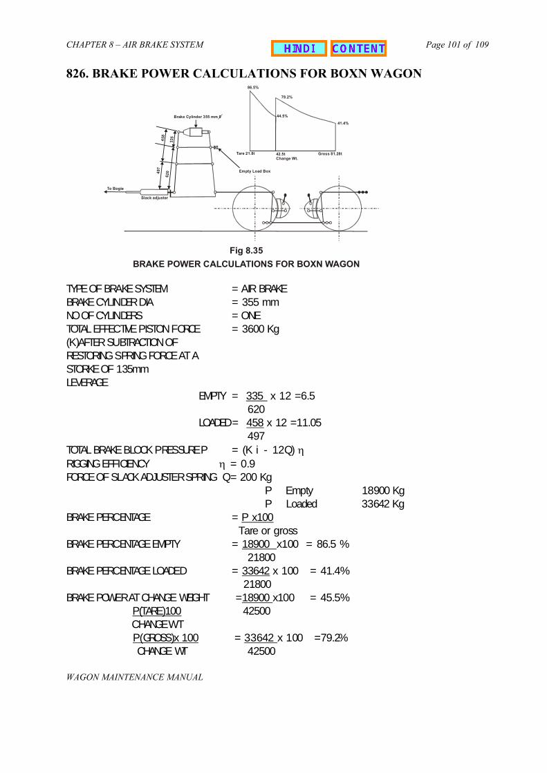
CHAPTER 8 – AIR BRAKE SYSTEM
WAGON M
Page 101 of 109
826. BRAKE POWER CALCULATIONS FOR BOXN WAGON
TYPE OF BRAKE CYNO OF CYTOTAL EF(K)AFTERRESTORINSTORKE OLEVERAGE
TOTAL BRRIGGING EFORCE OF
BRAKE PE
BRAKE PE
BRAKE PE
BRAKE PO
86.5%
AINTENANCE MANUAL
BRAKE SYSTEM = AIR BRAKELINDER DIA = 355 mmLINDERS = ONE
FECTIVE PISTON FORCE = 3600 Kg SUBTRACTION OFG SPRING FORCE AT AF 135mm
EMPTY = 335 x 12 =6.5 620
LOADED= 458 x 12 =11.05 497
AKE BLOCK PRESSUREP = (K i - 12Q) ηFFICIENCY η = 0.9 SLACK ADJUSTER SPRING Q= 200 Kg
P Empty 18900 KgP Loaded 33642 Kg
RCENTAGE = P x100 Tare or gross
RCENTAGE EMPTY = 18900 x100 = 86.5 % 21800
RCENTAGE LOADED = 33642 x 100 = 41.4% 21800
WER AT CHANGE WEIGHT =18900 x100 = 45.5%P(TARE)100 42500
CHANGE WT P(GROSS)x 100 = 33642 x 100 =79.2% CHANGE WT 42500
Fig 8.35
BRAKE POWER CALCULATIONS FOR BOXN WAGON
Empty Load Box
To Bogie
Slack adjuster
Gross 81.28t
41.4%
44.5%
79.2%
42.5tChange Wt.
Tare 21.8t
335
458
49 7
6 20
Brake Cylinder 355 mm 0

CHAPTER 8 – AIR BRAKE SYSTEM
WAGON MAINTENANCE MA
Page 102 of 109
827. BRAKE RIGGING
With SlidingBrake beams[22w, 22NL]
With Hanging Brake Beams
[22 W (M)]
Bogie Brake Rigging
- Hand Brake Arrangement- Empty Load Device- Under Gearing Arrangement with slack adjuster
Body UnderframeBrake Rigging
Brake Rigging
A. INTRODUCTION
The Brake Rigging is provided to control the speed of a wagon by transferring thebraking force from Brake Cylinder to wheel treads.
The Brake Rigging can be divided into two groups, as can be seen in the figure above.
I. Hand Brake
General
The Hand Brake provides a means of attaining retarding force with the brake shoe.The BOXN & BCN wagon are equipped with side operated Hand Brake.
Constructional detail
6. Hand Brake 7. Hand Brake 8. Bevel Gear s9. Hand Brake 10. Hand Brake
The Hand Brake
Fig. No. 8.36 Hand Brake Arrangement
NUAL
WheelSpindle rodetscrew rod with nutconnecting links
1. Hand Brake equalising levers2. Support Bracket3. Hand Brake pull rod4. Bevel gear box5. Sleeve for spindle.
arrangement consists of the following components:-
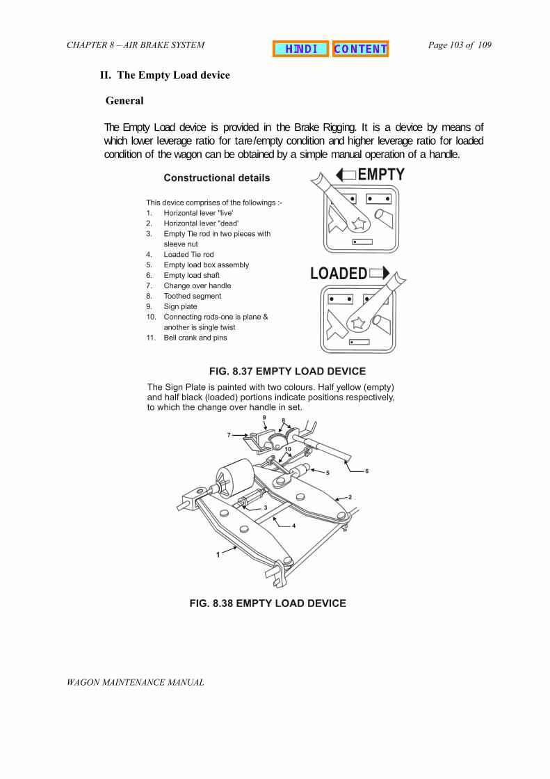
CHAPTER 8 – AIR BRAKE SYSTEM
WAGON MAINTENANCE MANUAL
Page 103 of 109
II. The Empty Load device
General
The Empty Load device is provided in the Brake Rigging. It is a device by means ofwhich lower leverage ratio for tare/empty condition and higher leverage ratio for loadedcondition of the wagon can be obtained by a simple manual operation of a handle.
FIG. 8.37 EMPTY LOAD DEVICE
This device comprises of the followings :-1. Horizontal lever "live'2. Horizontal lever "dead'3. Empty Tie rod in two pieces with
sleeve nut4. Loaded Tie rod5. Empty load box assembly6. Empty load shaft7. Change over handle8. Toothed segment9. Sign plate10. Connecting rods-one is plane &
another is single twist11. Bell crank and pins
Constructional details EMPTY
LOADED
The Sign Plate is painted with two colours. Half yellow (empty) and half black (loaded) portions indicate positions respectively, to which the change over handle in set.
FIG. 8.38 EMPTY LOAD DEVICE
1
10
7
9 8
6 5
3
4
2

CHAPTER 8 – AIR BRAKE SYSTEM
WAGON MAINTENANC
Page 104 of 109
III. Components
Depending on the brake beam arrangements, brake rigging can be of followingtwo types.
Sliding Brake Beam
For Cstructu
For Chavinbrake
Hanging brakebeam withoutadditional brakebeam support
E MA
ASNUB 22W Bogie, the brake beam is of sliding type having fabricatedral steel construction with integral brake head.
ASNUB 22-NL, NLB, NLM & HS bogies, the brake beam is of sliding type,g fabricated box-steel structure with integral cast steel pieces for strut &-heads.
MAIN PULL ROD
EQUALISING LEVER
BRAKE BEAM
PUSH ROD
END PULL ROD
NUAL
Fig 8.40
SIDE FRAMEHANGERBRACKET BRAKE HEAD
END PULL ROD
EQALISING LEVER
BRAKE BEAM
PUSH BEAM
HANGER

CHAPTER 8 – AIR BRAKE SYSTEM
WAGON M
Page 105 of 109
Body Underframe Components
Details of components and assemblies used in various types of brake riggingarrangements are given below and shown in figure;
Fig 8.41
ADDITIONALBRAKE BEAM HANGER SUPENSION
BRACKET
1. End pull rod2. Equalising lever3. Push rod4. Brake beam5. Brake head assembly
6. Brake beam hanger7. Brake block8. Brake show key9. Brake wear plate10. Brake gear pins,
washers, cotters
11. Short pull rod12. Long pull rod13. Control rod with head14. Horizontal lever15. Empty tie rod with sleeve nut16. Loaded tie rod17. Empty load device18. Hand brake pull rod19. Hand Brake arrangement20. Slack Adjuster
Hanging brake beam withadditional brake beam support.
AINTENANCE MANUAL
Fig. No
. 8.42 Body Underframe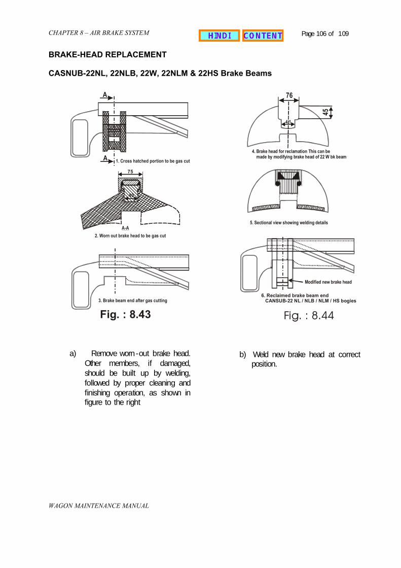
CHAPTER 8 – AIR BRAKE SYSTEM
WAGON
Page 106 of 109
BRAKE-HEAD REPLACEMENT
CASNUB-22NL, 22NLB, 22W, 22NLM & 22HS Brake Beams
A 76
MAINTENANCE MANUAL
Fig. : 8.43
2. Worn out brake head to be gas cut A-A
75
40
3. Brake beam end after gas cutting
1. Cross hatched portion to be gas cutA
a) Remove worn-out brake head.Other members, if damaged,should be built up by welding,followed by proper cleaning andfinishing operation, as shown infigure to the right
4. Brake head for reclamation This can be made by modifying brake head of 22 W bk beam
5. Sectional view showing welding details
45
4 1
Fig. : 8.44
6. Reclaimed brake beam end CANSUB-22 NL / NLB / NLM / HS bogies
Modified new brake head
b) Weld new brake head at correctposition.

CHAPTER 8 – AIR BRAKE SYSTEM
WAGON
Page 107 of 109
CASNUM 22W (M) Brake beam
a) Remove split pin and washer from brake beam ends. Remove pin securing brakeshoe adjuster with brake beam by removing
b) Take the Brake Heads out of the Brake Beam along with Brake shoe adjusterc) Disengage brake shoe adjuster form brake head by removing bolt after disengaging
split pin, nut, cover, spring and adjusting piece.d) Assemble the new brake head with brake shoe adjuster.e) Secure brake heads on brake beam end by putting washer and split pin.
Holes of end pull rod pins to be used for brake adjustment as per diameter ofwheels.
Hole Wheel diameter on tread
A Between 1000 & 982B Between 981 & 963C Between 962 & 944D Between 943 & 925E Between 924 & 906
The figure on next page shows where the holes are.
MAINTENANCE MANUAL
FIG. : 8.45
A B C D E

CHAPTER 8 – AIR BRAKE SYSTEM
WAGON MAINTENANCE MANUAL
Page 108 of 109
828. COMPOSITION BRAKE BLOCK
Indian Railways using cast iron brake blocks for braking on freight stock. Thefrictional properties of cast iron brake blocks decline with the increase in speedsresulting in increased braking distance. The composition brake block has the followingbenefits as compared to cast iron brake blocks:-
i) Reduced braking distance due to uniform coefficient of friction .ii) Reduced weight.iii) Longer life due to reduced wear of composition brake blocks.iv) Reduced noise during braking.
Initially L—type composition brake blocks were developed and tried out. Aftersuccessful trials the decision was taken to progressively switch over to L- typecomposition brake blocks. Presently following firms are approved for regular supply ofL- type composition brake blocks:-
1. M/s Rane Brake Lining, Chennai.2. M/s Stone India Ltd., Calcutta.3. M/s Escorts Ltd,. Faridabad.4. M/s Allied Nippon
Cast iron brake blocks can be replaced by L- type composition brake blocks andcondemning limit is the same as that of CI.
K-type composition brake blocks having higher average coefficient of friction arebeing developed. Moreover adoption of K-type brake block requires change in brakerigging. Development of K-type brake blocks at testing stage at present.
Do’s and Don’ts for fitment of Composition Brake Blocks
The following procedure shall be followed to ensure proper fitment of compositionbrake blocks;
To be done
i) Brake block shoe key shall be of spring steel as per RDSO drawingii) Brake head shall be of spring steel as per RDSO drawingiii) Brake block taper should match with the wheel taper i.e. lower thickness of brake
block towards flange of wheel disc and higher thickness towards other side ofwheel flange
iv) Sufficient clearance should be created by rotating the barrel of slack adjuster forfitment of brake block
v) The brake block should be fitted from the top of wheel and pressed down so thatit sits properly on brake head.

CHAPTER 8 – AIR BRAKE SYSTEM
WAGON MAINTENANCE MANUAL
Page 109 of 109
vi) Key shall be inserted from the top and slightly hammered so that it sits properlywith the brake head. Slight hammering requirements indicates that the brakeshoe key is made of proper material and as per drawings.
vii) Split pins shall be inserted through the brake head whole passing the edge ofbrake shoe key and ends of split pins should be bent.
Not to be done:
i) No hammering should be done for fitment of brake blocks.ii) Brake blocks should not be dropped.iii) Brake blocks should be handled properly and carefully to avoid damages such as
chipping / cracking.iv) Do not store on radius side. ( the best way is to store them on the side ways).v) Do not strike key if stopped by brake block nib.vi) Composition and cost iron brake blocks shall not be fitted on same brake beam.vii) Avoid fitment of composition and cast iron brake block on the same rake to get
optimum wear life out of the composition brake blocks.