Embed Size (px)
Citation preview
1 FORM NO. L-20143-M-1216
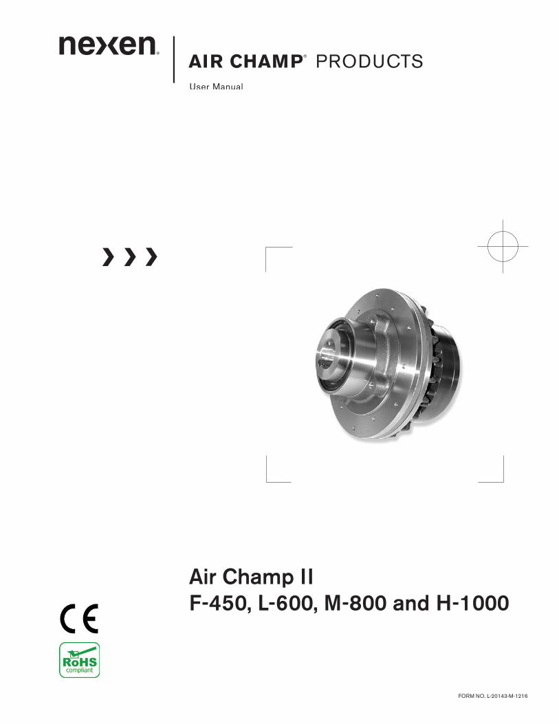
Air Champ IIF-450, L-600, M-800 and H-1000
AIR CHAMP PRODUCTS
2FORM NO. L-20143-M-1216
Copyright 2016 Nexen Group, Inc.
Nexen Group, Inc.560 Oak Grove Parkway
Vadnais Heights, Minnesota 55127
ISO 9001 Certified
This document is the original, non-translated, version.
Conformity Declaration: In accordance with Appendix II B of CE Machinery Directive (2006/42/EC):
A Declaration of Incorporation of Partly Completed Machinery evaluation for the applicable EU directives was carried out for this product in accordance with the Machinery Directive. The declaration of incorporation is set out in writing in a separate document and can be requested if required.
This machinery is incomplete and must not be put into service until the machinery into which it is to be incorporated has been declared in conformity with the applicable provisions of the Directive.
Read this manual carefully before installation and operation. Follow Nexen’s instructions and integrate this unit into your system with care. This unit should be installed, operated and maintained by qualified personnel ONLY. Improper installation can damage your system, cause injury or death. Comply with all applicable codes.
DANGER
In accordance with Nexen’s established policy of constant product improvement, the specifications contained in this manual are subject to change without notice. Technical data listed in this manual are based on the latest information available at the time of printing and are also subject to change without notice.
Technical Support: 800-843-7445 (651) 484-5900
www.nexengroup.com
3 FORM NO. L-20143-M-1216
Table of Contents
General Specifications -------------------------------------------------------------------------------------------------------------------------- 4
General Safety Precautions ------------------------------------------------------------------------------------------------------------------- 4
Installation -------------------------------------------------------------------------------------------------------------------------------------------- 5
Friction Facing Admustment ------------------------------------------------------------------------------------------------------------------ 7
Lubrication ------------------------------------------------------------------------------------------------------------------------------------------- 7
Air Connections ------------------------------------------------------------------------------------------------------------------------------------ 8
Operation -------------------------------------------------------------------------------------------------------------------------------------------- 8
Troubleshooting ------------------------------------------------------------------------------------------------------------------------------------ 9
Parts Replacement ----------------------------------------------------------------------------------------------------------------------------- 10
Replacement Parts ----------------------------------------------------------------------------------------------------------------------------- 13
Warranty -------------------------------------------------------------------------------------------------------------------------------------------- 14
4FORM NO. L-20143-M-1216
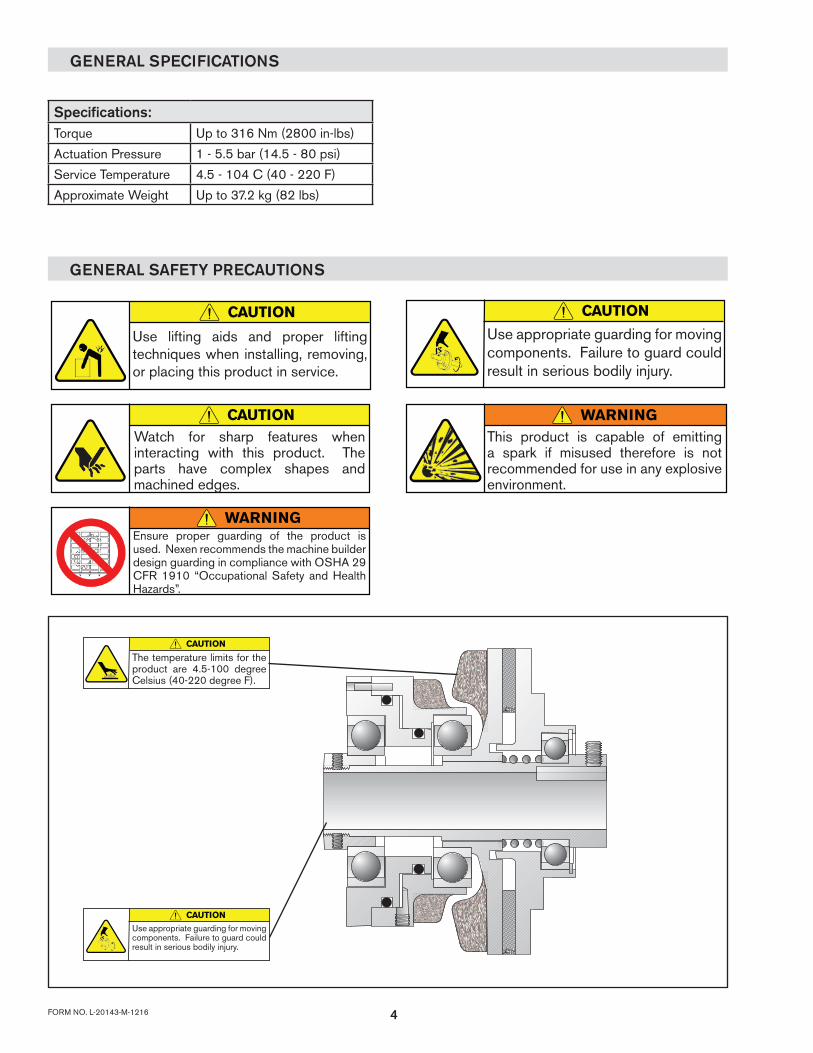
GENERAL SPECIFICATIONS
GENERAL SAFETY PRECAUTIONS
Specifications:Torque Up to 316 Nm (2800 in-lbs)
Actuation Pressure 1 - 5.5 bar (14.5 - 80 psi)
Service Temperature 4.5 - 104 C (40 - 220 F)
Approximate Weight Up to 37.2 kg (82 lbs)
CAUTION
Use lifting aids and proper lifting techniques when installing, removing, or placing this product in service.
CAUTIONWatch for sharp features when interacting with this product. The parts have complex shapes and machined edges.
CAUTION
Use appropriate guarding for moving components. Failure to guard could result in serious bodily injury.
WARNINGThis product is capable of emitting a spark if misused therefore is not recommended for use in any explosive environment.
WARNINGEnsure proper guarding of the product is used. Nexen recommends the machine builder design guarding in compliance with OSHA 29 CFR 1910 “Occupational Safety and Health Hazards”.
CAUTION
Use appropriate guarding for moving components. Failure to guard could result in serious bodily injury.
CAUTION
The temperature limits for the product are 4.5-100 degree Celsius (40-220 degree F).
5 FORM NO. L-20143-M-1216
INSTALLATION
Air Champ II
Shaft
19 18
17
16
FIGURE 1
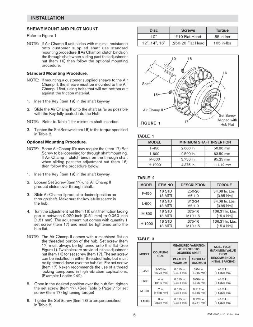
SHEAVE MOUNT AND PILOT MOUNT
Refer to Figure 1.
NOTE: If Air Champ II unit slides with minimal resistance onto customer supplied shaft use standard mounting procedure. If Air Champ II clutch binds on the through shaft when sliding past the adjustment nut (Item 16) then follow the optional mounting procedure.
Standard Mounting Procedure.
NOTE: If mounting a customer supplied sheave to the Air Champ II, the sheave must be mounted to the Air Champ II first, using bolts that will not bottom out against the friction material.
1. Insert the Key (Item 19) in the shaft keyway
2. Slide the Air Champ II onto the shaft as far as possible with the Key fully seated into the Hub
NOTE: Refer to Table 1 for minimum shaft insertion.
3. Tighten the Set Screws (Item 18) to the torque specified in Table 2.
Optional Mounting Procedure.
NOTE: Some Air Champ II’s may require the (Item 17) Set Screw to be loosening for through shaft mounting. If Air Champ II clutch binds on the through shaft when sliding past the adjustment nut (Item 16) then follow the procedure below.
1. Insert the Key (Item 19) in the shaft keyway.
2. Loosen Set Screw (Item 17) until Air Champ II product slides over through shaft.
3. Slide Air Champ II product to desired position on through shaft. Make sure the key is fully seated in the hub.
4. Turn the adjustment nut (Item 16) unit the friction facing gap is between 0.020 inch [0.51 mm] to 0.060 inch [1.51 mm]. The adjustment nut comes with quantity 1 set screw (Item 17) and must be tightened onto the hub flat.
NOTE: The Air Champ II comes with a machined flat on the threaded portion of the hub. Set screw (Item 17) must always be tightened onto this flat (See Figure 1). Two holes are provided in the adjustment nut (Item 16) for set screw (Item 17). The set screw can be installed in either threaded hole, but must be tightened down over the hub flat. For set screw (Item 17) Nexen recommends the use of a thread locking compound in high vibration applications, (Example: Loctite 242).
5. Once in the desired position over the hub flat, tighten the set screw (Item 17). (See Table 5 Page 7 for set screw (Item 17) tightening torque)
6. Tighten the Set Screw (Item 18) to torque specified in Table 2.
TABLE 1LEDOM NOITRESNITFAHSMUMINIM
054-F .nI000.2 mm08.05006-L .nI005.2 mm05.36008-M .nI057.3 mm52.590001-H .nI573.4 mm21.111
TABLE 2
LEDOM .ONMETI NOITPIRCSED EUQROT
054-FDTS81RTM81
02-052.0.1-6M
.sbL.nI80.43]mN58.3[
006-LDTS81RTM81
42-213.0.1-6M
.sbL.nI80.43]mN58.3[
008-MDTS81RTM81
61-573.5.1-01M
.sbL.nI13.631]mN4.51[
0001-HDTS81RTM81
61-573.5.1-01M
.sbL.nI13.631]mN4.51[
TABLE 3
LEDOM GNILPUOCEZIS
NOITAIRAVDERUSAEM081STNIOPTATRAPASEERGED
TAOLFLAIXAEULAVMUMIXAM(
MORFDEDNEMMOCER
)GNICAPSLAITINILELLARAPMUMIXAM
RALUGNAMUMIXAM
054-F.nI8/5-2
]mm57.66[.nI510.0
]mm183.0[.nI40.0
]mm610.1[.nI8/1+
]mm573.1+[
006-L.nI4
]mm6.101[.nI510.0
]mm183.0[.nI460.0]mm526.1[
.nI8/1+]mm573.1+[
008-M.nI7
]mm8.771[.nI510.0
]mm183.0[.nI211.0
]mm548.2[.nI8/1+
]mm573.1+[
0001-H.nI8
]mm2.302[.nI510.0
]mm183.0[.nI821.0
]mm152.3[.nI8/1+
]mm573.1+[
Disc Screws Torque
10" #10 Flat Head 65 in-lbs
12", 14", 16" .250-20 Flat Head 105 in-lbs
18
Set ScrewAligned with
Hub Flat
6FORM NO. L-20143-M-1216
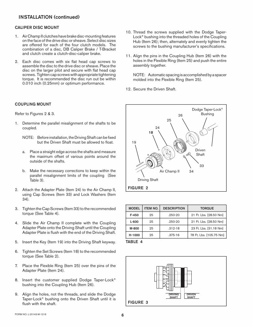
COUPLING MOUNT
Refer to Figures 2 & 3.
1. Determine the parallel misalignment of the shafts to be coupled.
NOTE: Before installation, the Driving Shaft can be fixed but the Driven Shaft must be allowed to float.
a. Place a straight edge across the shafts and measure the maximum offset of various points around the outside of the shafts.
b. Make the necessary corrections to keep within the parallel misalignment limits of the coupling (See Table 3).
2. Attach the Adapter Plate (Item 24) to the Air Champ II, using Cap Screws (Item 33) and Lock Washers (Item 34).
3. Tighten the Cap Screws (Item 33) to the recommended torque (See Table 4).
4. Slide the Air Champ II complete with the Coupling Adapter Plate onto the Driving Shaft until the Coupling Adapter Plate is flush with the end of the Driving Shaft.
5. Insert the Key (Item 19) into the Driving Shaft keyway.
6. Tighten the Set Screws (Item 18) to the recommended torque (See Table 2).
7. Place the Flexible Ring (Item 25) over the pins of the Adapter Plate (Item 24).
8. Insert the customer supplied Dodge Taper-Lock®
bushing into the Coupling Hub (Item 26).
9. Align the holes, not the threads, and slide the Dodge Taper-Lock® bushing onto the Driven Shaft until it is flush with the shaft.
TABLE 4
FIGURE 3
LEDOM .ONMETI NOITPIRCSED EUQROT
054-F 52 02-052. ]mN05.82[.sbL.tF12
006-L 52 02-052. ]mN05.82[.sbL.tF12
008-M 52 81-213. ]mN81.13[.sbL.tF32
0001-H 52 61-573. ]mN57.501[.sbL.tF87
24
2526
34
33
19
18
Driving Shaft
Driven Shaft
Dodge Taper-Lock® Bushing
Air Champ II
FIGURE 2
INSTALLATION (continued)
10. Thread the screws supplied with the Dodge Taper-Lock® bushing into the threaded holes of the Coupling Hub (Item 26); then, alternately and evenly tighten the screws to the bushing manufacturer’s specifications.
11. Align the pins in the Coupling Hub (Item 26) with the holes in the Flexible Ring (Item 25) and push the entire assembly together.
NOTE: Automatic spacing is accomplished by a spacer molded into the Flexible Ring (Item 25).
12. Secure the Driven Shaft.
CALIPER DISC MOUNT
1. Air Champ II clutches have brake disc-mounting features on the face of the drive disc or sheave. Select disc sizes are offered for each of the four clutch models. The combination of a disc, DB Caliper Brake / T-Bracket and clutch create a clutch-disc-caliper brake.
2. Each disc comes with six flat head cap screws to assemble the disc to the drive disc or sheave. Place the disc on the larger pilot and secure with flat head cap screws. Tighten cap screws with appropriate tightening torque. It is recommended the disc run out be within 0.010 inch (0.25mm) or optimum performance.

7 FORM NO. L-20143-M-1216
FRICTION FACING ADJUSTMENT
Refer to Figure 4.
1. Ensure the Set Screw (Item 17) that locks the Adjustment Nut (Item 16) is released to allow the Adjustment Nut to be rotated on the Hub.
2. Using a 0.020 In. [0.508 mm] and a 0.060 In. [1.514 mm] feeler gauge, check the gap between the Friction Disc and the Friction Facing.
a. If the gap is less than 0.020 In. [0.508 mm], rotate the Adjustment Nut counterclockwise until one set screw hole is over the flat on the Hub and the 0.020 In. [0.508 mm] feeler gauge can be inserted.
b. If the gap is greater than 0.060 In. [1.514 mm], rotate the Adjustment Nut clockwise until one set screw hole is over the flat on the Hub and the 0.060 In. [1.514 mm] feeler gauge can not be inserted.
3. Tighten the Set Screw to the recommended torque (See Table 5).
NOTE: Do not adjust the gap to less than 0.020 In. [0.508 mm]. The Air Champ II will not disengage if the gap is closed. Always tighten Set Screw (Item 17) on Hub Flat.
17
16
Check Friction Facing gap here.
FIGURE 4
TABLE 5
NOTENexen pneumatically actuated devices require clean, pressure regulated air for maximum performance and life. All seals in Nexen pneumatically operated devices are lubricated for life, and do not require additional lubrication.
However, some customers prefer to use an air line lubricator, which injects oil into the pressurized air, forcing an oil mist into the air chamber. This is acceptable, but care must be taken to ensure once an air mist lubrication system is used, it is continually used over the life of the product as the oil mist may wash free the factory installed lubrication.
Locate the lubricator above and within ten feet of the product, and use low viscosity oil such as SAE-10.
Synthetic lubricants are not recommended.
Nexen product's bearings are shielded and pre-lubricated, and require no further lubrication.
LUBRICATOR DRIP RATE SETTINGS
1. Close and disconnect the air line from the unit.
2. Turn the Lubricator Adjustment Knob counterclockwise three complete turns.
3. Open the air line.
LUBRICATION
CAUTION
These settings are for Nexen supplied lubricators. If you are not using a Nexen lubricator, calibration must follow the manufacturer's suggested procedure.
4. Close the air line to the unit when a drop of oil forms in the Lubricator Sight Gage.
5. Connect the air line to the unit.
6. Turn the Lubricator Adjustment Knob clockwise until closed.
7. Turn the Lubricator Adjustment Knob counterclockwise one-third turn.
8. Open the air line to the unit.
MODEL ITEM NO. DESCRIPTION TORQUEF-450 17 STD
17 MTR.190-32M4-0.7
37 in-lbs4.18 Nm
L-600 17 STD17 MTR
.190-32M4-0.7
37 in-lbs4.18 Nm
M-800 17 STD17 MTR
.250-28M6-1.0
80 in-lbs9.04 Nm
H-1000 17 STD17 MTR
.250-28M6-1.0
80 in-lbs9.04 Nm

8FORM NO. L-20143-M-1216
AIR CONNECTIONS
An Air Line (Item 20) is furnished and air controls with 1/8 NPT ports are recommended. Where long air lines are required, a Quick Exhaust Valve (Product No. 945100) is recommended to ensure rapid disengagement.
NOTE: Because of the necessary movement of the air chamber and Air Line upon engagement, flexible tubing or air lines must be used on the Air Champ II.
Due to bearings seal drag, the outer portion or the Air Champ II will rotate when it is engaged. Rest the air line against a support that is parallel to the centerline of the Air Champ II to stop this rotation.
NOTE: Pressure should be regulated to the minimum required for sufficient torque to maximize bearing life.
AirSupply
Brake or Clutch
GaugeRegulator
FilterDryer
Typical Clutch or Brake Control Circuit
3/2 (3 Way)N.C. Valve
Quick Exhaust Valve
AIR PRESSURE: 8 BAR (120 PSI) ABSOLUTE MAX 0 BAR (0 PSI) ABSOLUTE MIN
NOTEFor quick response, Nexen recommends a quick exhaust valve and short air lines between the Control Valves and the product. Align the air inlet ports to a down position to allow condensation to drain out of the air chambers of the product.
CAUTIONLow air pressure will cause slippage and overheating. Excessive air pressure will cause abrupt starts and stops, reducing product life.
All Nexen pneumatically actuated devices require clean and dry air, which meet or exceeds ISO 8573.1:2001 Class 4.4.3 quality.
The following is a common air supply scheme used with this product. This is an example and not an all-inclusive list. All air circuits to be used with this product must be designed following ISO-4414 guidelines.
OPERATION
WARNING
Never exceed maximum operating speeds listed for your product. (See Table 6).
CAUTION
The temperature limits for this product line are 4.5-100 Degree Celsius (40-220 Degree F).
CAUTIONNever exceed life of facing material. Facing life depends on the volume of material and the total energy over the life of the unit. Expected life (in hrs) can be found by: Time=Volume/(Power*Wear Rate).
TABLE 6
Size Max RPM
F-450 3,600L-600 3,600M-800 1,800H-1000 1,800
WARNINGEnsure proper guarding of the product is used. Nexen recommends the machine builder design guarding in compliance with OSHA 29 CFR 1910 “Occupational Safety and Health Hazards”.
9 FORM NO. L-20143-M-1216
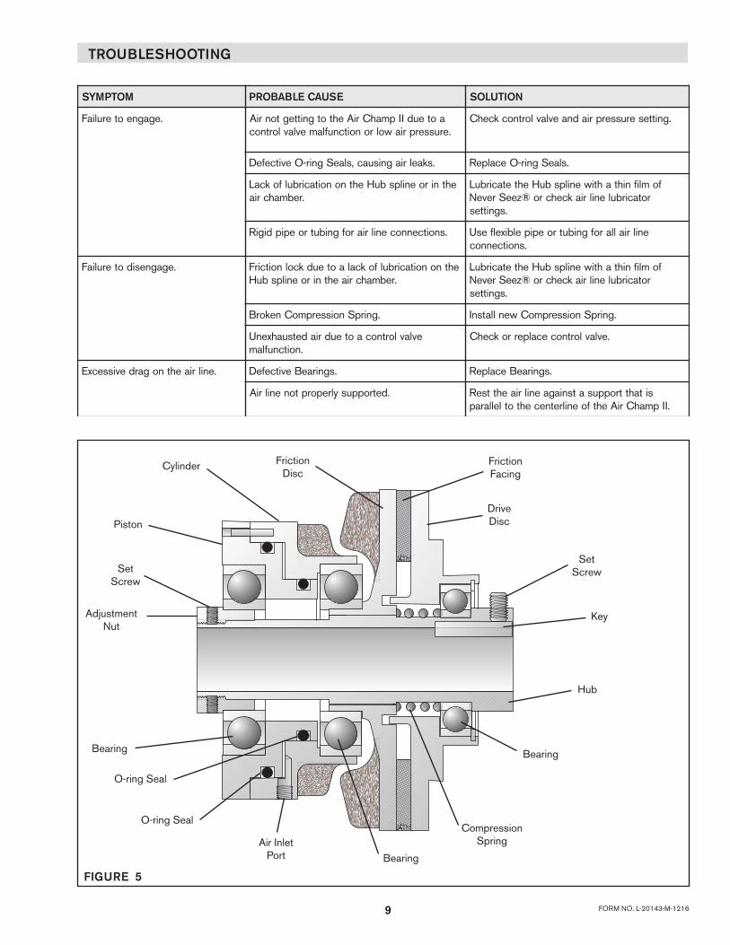
TROUBLESHOOTING
Drive Disc
Friction Facing
Cylinder
Piston
Friction Disc
Set ScrewSet
Screw
Adjustment Nut
Bearing
O-ring Seal
O-ring Seal
Air Inlet Port Bearing
Compression Spring
Bearing
Hub
Key
FIGURE 5
MOTPMYS ESUACELBABORP NOITULOS
.egagneoteruliaF aoteudIIpmahCriAehtotgnittegtonriA.erusserpriawolronoitcnuflamevlavlortnoc
.gnitteserusserpriadnaevlavlortnockcehC
.skaelriagnisuac,slaeSgnir-OevitcefeD .slaeSgnir-OecalpeR
ehtniroenilpsbuHehtnonoitacirbulfokcaL.rebmahcria
fomlifnihtahtiwenilpsbuHehtetacirbuLrotacirbulenilriakcehcro®zeeSreveN
.sgnittes
.snoitcennocenilriarofgnibutroepipdigiR enilriallarofgnibutroepipelbixelfesU.snoitcennoc
.egagnesidoteruliaF ehtnonoitacirbulfokcalaoteudkcolnoitcirF.rebmahcriaehtniroenilpsbuH
fomlifnihtahtiwenilpsbuHehtetacirbuLrotacirbulenilriakcehcro®zeeSreveN
.sgnittes
.gnirpSnoisserpmoCnekorB .gnirpSnoisserpmoCwenllatsnI
evlavlortnocaoteudriadetsuahxenU.noitcnuflam
.evlavlortnocecalperrokcehC
.enilriaehtnogardevissecxE .sgniraeBevitcefeD .sgniraeBecalpeR
.detroppusylreporptonenilriA sitahttroppusatsniagaenilriaehttseR.IIpmahCriAehtfoenilretnecehtotlellarap
10FORM NO. L-20143-M-1216
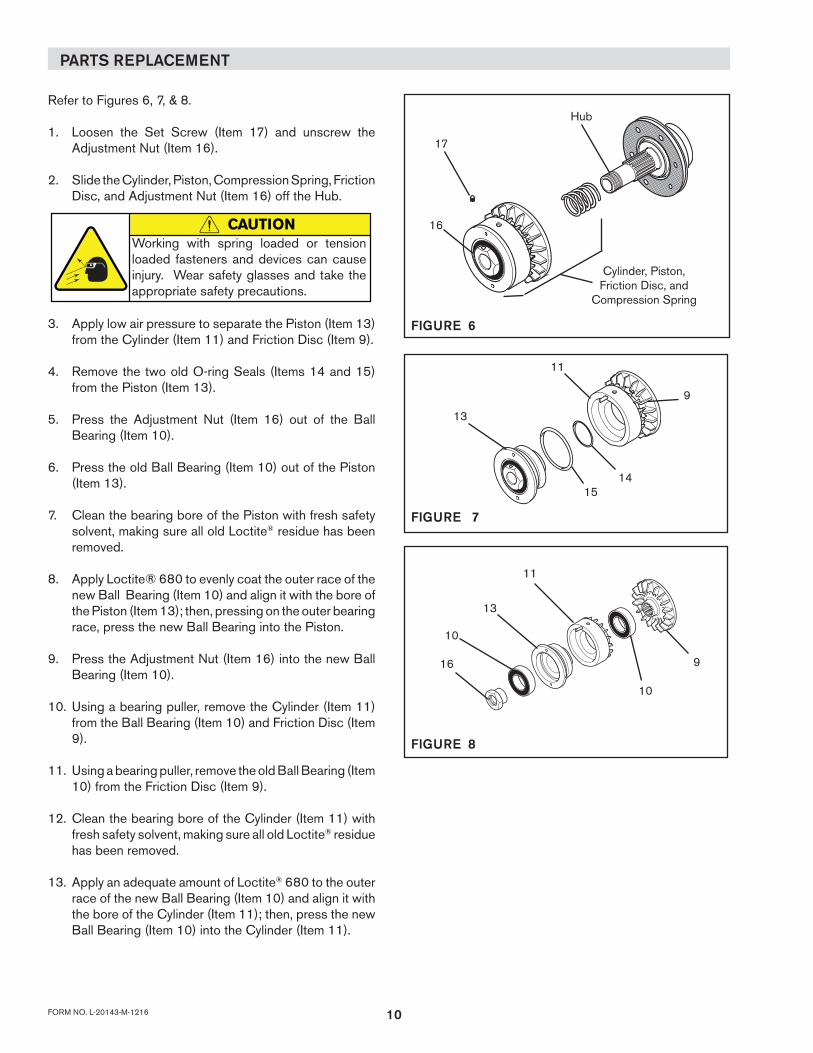
PARTS REPLACEMENT
Refer to Figures 6, 7, & 8.
1. Loosen the Set Screw (Item 17) and unscrew the Adjustment Nut (Item 16).
2. Slide the Cylinder, Piston, Compression Spring, Friction Disc, and Adjustment Nut (Item 16) off the Hub.
3. Apply low air pressure to separate the Piston (Item 13) from the Cylinder (Item 11) and Friction Disc (Item 9).
4. Remove the two old O-ring Seals (Items 14 and 15) from the Piston (Item 13).
5. Press the Adjustment Nut (Item 16) out of the Ball Bearing (Item 10).
6. Press the old Ball Bearing (Item 10) out of the Piston (Item 13).
7. Clean the bearing bore of the Piston with fresh safety solvent, making sure all old Loctite® residue has been removed.
8. Apply Loctite® 680 to evenly coat the outer race of the new Ball Bearing (Item 10) and align it with the bore of the Piston (Item 13); then, pressing on the outer bearing race, press the new Ball Bearing into the Piston.
9. Press the Adjustment Nut (Item 16) into the new Ball Bearing (Item 10).
10. Using a bearing puller, remove the Cylinder (Item 11) from the Ball Bearing (Item 10) and Friction Disc (Item 9).
11. Using a bearing puller, remove the old Ball Bearing (Item 10) from the Friction Disc (Item 9).
12. Clean the bearing bore of the Cylinder (Item 11) with fresh safety solvent, making sure all old Loctite® residue has been removed.
13. Apply an adequate amount of Loctite® 680 to the outer race of the new Ball Bearing (Item 10) and align it with the bore of the Cylinder (Item 11); then, press the new Ball Bearing (Item 10) into the Cylinder (Item 11).
FIGURE 8
10
13
11
10
916
FIGURE 7
13
11
9
1415
Hub
16
FIGURE 6
17
Cylinder, Piston, Friction Disc, and
Compression Spring
CAUTIONWorking with spring loaded or tension loaded fasteners and devices can cause injury. Wear safety glasses and take the appropriate safety precautions.
11 FORM NO. L-20143-M-1216
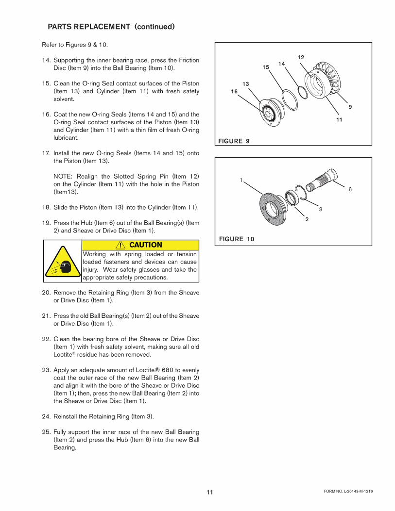
Refer to Figures 9 & 10.
14. Supporting the inner bearing race, press the Friction Disc (Item 9) into the Ball Bearing (Item 10).
15. Clean the O-ring Seal contact surfaces of the Piston
(Item 13) and Cylinder (Item 11) with fresh safety solvent.
16. Coat the new O-ring Seals (Items 14 and 15) and the O-ring Seal contact surfaces of the Piston (Item 13) and Cylinder (Item 11) with a thin film of fresh O-ring lubricant.
17. Install the new O-ring Seals (Items 14 and 15) onto the Piston (Item 13).
NOTE: Realign the Slotted Spring Pin (Item 12) on the Cylinder (Item 11) with the hole in the Piston (Item13).
18. Slide the Piston (Item 13) into the Cylinder (Item 11).
19. Press the Hub (Item 6) out of the Ball Bearing(s) (Item 2) and Sheave or Drive Disc (Item 1).
20. Remove the Retaining Ring (Item 3) from the Sheave or Drive Disc (Item 1).
21. Press the old Ball Bearing(s) (Item 2) out of the Sheave or Drive Disc (Item 1).
22. Clean the bearing bore of the Sheave or Drive Disc (Item 1) with fresh safety solvent, making sure all old Loctite® residue has been removed.
23. Apply an adequate amount of Loctite® 680 to evenly coat the outer race of the new Ball Bearing (Item 2) and align it with the bore of the Sheave or Drive Disc (Item 1); then, press the new Ball Bearing (Item 2) into the Sheave or Drive Disc (Item 1).
24. Reinstall the Retaining Ring (Item 3).
25. Fully support the inner race of the new Ball Bearing (Item 2) and press the Hub (Item 6) into the new Ball Bearing.
FIGURE 10
6
3
2
1
FIGURE 9
9
11
121415
1316
PARTS REPLACEMENT (continued)
CAUTIONWorking with spring loaded or tension loaded fasteners and devices can cause injury. Wear safety glasses and take the appropriate safety precautions.
12FORM NO. L-20143-M-1216
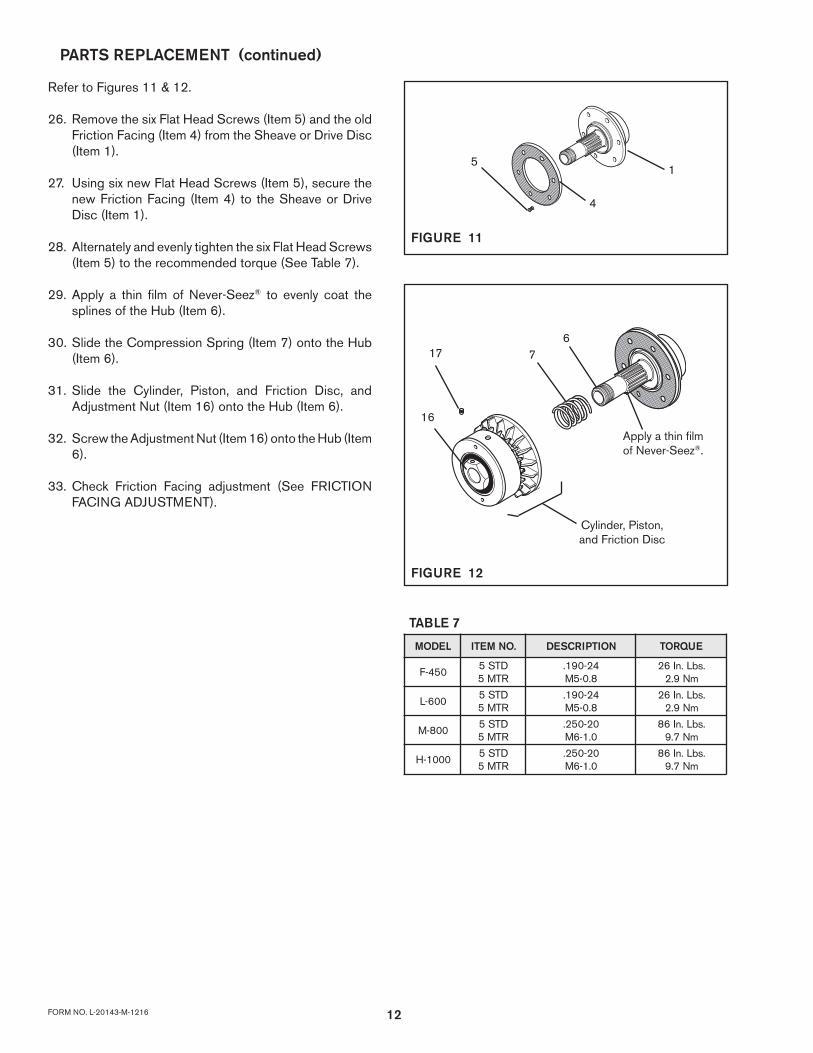
Refer to Figures 11 & 12.
26. Remove the six Flat Head Screws (Item 5) and the old Friction Facing (Item 4) from the Sheave or Drive Disc (Item 1).
27. Using six new Flat Head Screws (Item 5), secure the new Friction Facing (Item 4) to the Sheave or Drive Disc (Item 1).
28. Alternately and evenly tighten the six Flat Head Screws (Item 5) to the recommended torque (See Table 7).
29. Apply a thin film of Never-Seez® to evenly coat the splines of the Hub (Item 6).
30. Slide the Compression Spring (Item 7) onto the Hub (Item 6).
31. Slide the Cylinder, Piston, and Friction Disc, and Adjustment Nut (Item 16) onto the Hub (Item 6).
32. Screw the Adjustment Nut (Item 16) onto the Hub (Item 6).
33. Check Friction Facing adjustment (See FRICTION FACING ADJUSTMENT).
TABLE 7
LEDOM .ONMETI NOITPIRCSED EUQROT
054-FDTS5RTM5
42-091.8.0-5M
.sbL.nI62mN9.2
006-LDTS5RTM5
42-091.8.0-5M
.sbL.nI62mN9.2
008-MDTS5RTM5
02-052.0.1-6M
.sbL.nI68mN7.9
0001-HDTS5RTM5
02-052.0.1-6M
.sbL.nI68mN7.9
PARTS REPLACEMENT (continued)
FIGURE 11
1
4
5
FIGURE 12
67
Apply a thin film of Never-Seez®.
17
16
Cylinder, Piston, and Friction Disc
13 FORM NO. L-20143-M-1216
18
19
9101112
1415
1310
17
16 63
2
7
14
5
8
6
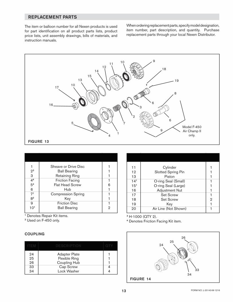
9Model F-450 Air Champ II
only.
FIGURE 13
ITEM DESCRIPTION QTY
1 Sheave or Drive Disc 1 23 Ball Bearing 1 3 Retaining Ring 1 44 Friction Facing 1 54 Flat Head Screw 6 6 Hub 1 71 Compression Spring 1 82 Key 1 9 Friction Disc 1 101 Ball Bearing 2
1 Denotes Repair Kit items.2 Used on F-450 only.
COUPLING
ITEM DESCRIPTION QTY
24 Adapter Plate 1 25 Flexible Ring 1 26 Coupling Hub 1 33 Cap Screw 4 34 Lock Washer 4
2625
24
3334
FIGURE 14
ITEM DESCRIPTION QTY
11 Cylinder 1 12 Slotted Spring Pin 1 13 Piston 1 141 O-ring Seal (Small) 1 151 O-ring Seal (Large) 1 16 Adjustment Nut 1 17 Set Screw 1 18 Set Screw 2 19 Key 1 20 Air Line (Not Shown) 1
3 H-1000 (QTY 2).4 Denotes Friction Facing Kit item.
REPLACEMENT PARTS
The item or balloon number for all Nexen products is used for part identification on all product parts lists, product price lists, unit assembly drawings, bills of materials, and instruction manuals.
When ordering replacement parts, specify model designation, item number, part description, and quantity. Purchase replacement parts through your local Nexen Distributor.
14FORM NO. L-20143-M-1216
Nexen Group, Inc.560 Oak Grove ParkwayVadnais Heights, MN 55127
800.843.7445Fax: 651.286.1099www.nexengroup.com
ISO 9001 Certified
WARRANTY
WarrantiesNexen warrants that the Products will (a) be free from any defects in material or workmanship for a period of 12 months from the date of shipment, and (b) will meet and perform in accordance with the specifications in any engineering drawing specifically for the Product that is in Nexen’s current product catalogue, or that is accessible at the Nexen website, or that is attached to this Quotation and that specifically refers to this Quotation by its number, subject in all cases to any limitations and exclusions set out in the drawing. NEXEN MAKES NO OTHER WARRANTY, EXPRESS OR IMPLIED, AND ALL IMPLIED WARRANTIES, INCLUDING WITHOUT LIMITATION, IMPLIED WARRANTIES OF MERCHANTABILITY AND FITNESS FOR A PARTICULAR PURPOSE ARE HEREBY DISCLAIMED. This warranty applies only if: (a) the Product has been installed, used and maintained in accordance with any applicable Nexen installation or maintenance manual for the Product; (b) the alleged defect is not attributable to normal wear and tear; (c) the Product has not been altered, misused or used for purposes other than those for which it was intended; and (d) Buyer has given written notice of the alleged defect to Nexen, and delivered the allegedly defective Product to Nexen, within one year of the date of shipment.
Exclusive RemedyThe exclusive remedy for the Buyer for any breach of any warranties provided in connection with this agreement will be, at the election of Nexen: (a) repair or replacement with new, serviceably used, or reconditioned parts or products; or (b) issuance of credit in the amount of the purchase price paid to Nexen by the Buyer for the Products.
Agent's AuthorityBuyer agrees that no agent, employee or representative of Nexen has authority to bind Nexen to any affirmation, representation, or warranty concerning the Products other than those warranties expressly set forth herein.
Limitation on Nexen’s LiabilityTO THE EXTENT PERMITTED BY LAW NEXEN SHALL HAVE NO LIABILITY TO BUYER OR ANY OTHER PERSON FOR INCIDENTAL DAMAGES, SPECIAL DAMAGES, CONSEQUENTIAL DAMAGES OR OTHER DAMAGES OF ANY KIND OR NATURE WHATSOEVER, WHETHER ARISING OUT OF BREACH OF WARRANTY OR OTHER BREACH OF CONTRACT, NEGLIGENCE OR OTHER TORT, OR OTHERWISE, EVEN IF NEXEN SHALL HAVE BEEN ADVISED OF THE POSSIBILITY OR LIKELIHOOD OF SUCH POTENTIAL LOSS OR DAMAGE. For all of the purposes hereof, the term "consequential damages" shall include lost profits, penalties, delay damages, liquidated damages or other damages and liabilities which Buyer shall be obligated to pay or which Buyer may incur based upon, related to or arising out of its contracts with its customers or other third parties. In no event shall Nexen be liable for any amount of damages in excess of amounts paid by Buyer for Products or services as to which a breach of contract has been determined to exist. The parties expressly agree that the price for the Products and the services was determined in consideration of the limitation on damages set forth herein and such limitation has been specifically bargained for and constitutes an agreed allocation of risk which shall survive the determination of any court of competent jurisdiction that any remedy herein fails of its essential purpose.
InspectionBuyer shall inspect all shipments of Products upon arrival and shall notify Nexen in writing, of any shortages or other failures to conform to these terms and conditions which are reasonably discoverable upon arrival without opening any carton or box in which the Products are contained. Such notice shall be sent within 14 days following arrival. All notifications shall be accompanied by packing slips, inspection reports and other documents necessary to support Buyer's claims. In addition to the foregoing obligations, in the event that Buyer receives Products that Buyer did not order, Buyer shall return the erroneously shipped Products to Nexen within thirty (30) days of the date of the invoice for such Products; Nexen will pay reasonable freight charges for the timely return of the erroneously shipped Products, and issue a credit to Buyer for the returned Products at the price Buyer paid for them, including any shipping expenses that Nexen charged Buyer. All shortages, overages and nonconformities not reported to Nexen as required by this section will be deemed waived.
Limitation on ActionsNo action, regardless of form, arising out of any transaction to which these terms and conditions are applicable may be brought by the Buyer more than one year after the cause of action has accrued.


![[XLS] · Web view450. 90. 450. 900. 900. 225. 450. 450. 900. 450. 225. 270. 4.5. 450. 450. 450. 450. 450. 450. 450. 450. 450. 900. 450. 450. 450. 112.5. 900. 900. 450. 112.5. 450](https://img.pdfslide.net/doc/110x75/5b3c17127f8b9a213f8d0b42/xls-web-view450-90-450-900-900-225-450-450-900-450-225-270-45.jpg)