Embed Size (px)
Citation preview
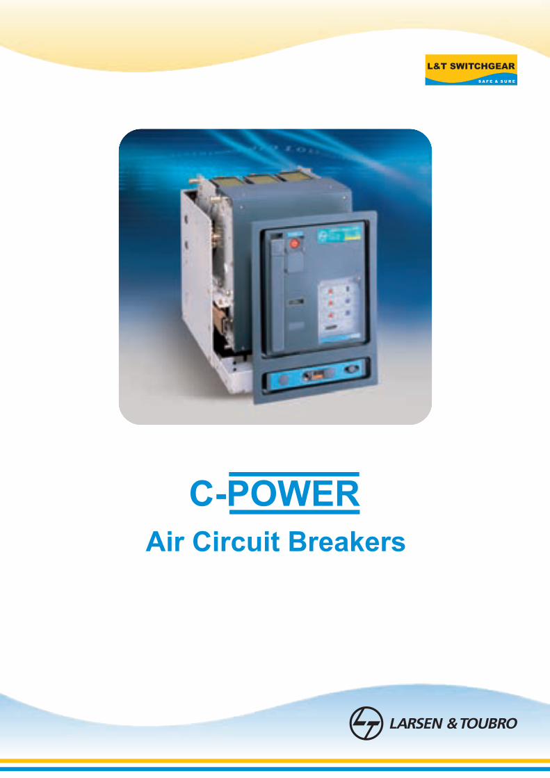
Air Circuit Breakers

About us
Larsen & Toubro is a technology-driven company that infuses engineering with imagination. The Company offers a wide range of advanced solutions in the field of Engineering, Construction, Electrical & Automation, Machinery and Information Technology.
L&T Switchgear, which forms part of the Electrical & Automation business, is India's largest manufacturer of low voltage switchgear, with the scale, sophistication and range to meet global benchmarks. With over five decades of experience in this field, the Company today enjoys a leadership position in the Indian market with growing presence in international markets.
It offers a complete range of products including controlgear, powergear, motor starters, energy meters, wires and host of other accessories. Most of our product lines conform to international standards, carry markings and are certified.
Switchgear Factory, Mumbai
Switchgear Factory, Ahmednagar
1
L&T’s Air Circuit Breakers (ACBs) are specially designed for extreme
tropical conditions and have a proven track record more than 30 years. Presently
more than 3,00,000 Air Circuit Breakers supplied by L&T are being used for diverse
applications. The Air Circuit Breakers provide technologically driven
solutions to meet customer needs.
Complete selectivity
Unique feature of lcu=lcs=lcw for 1 second across the entire range. This ensures
complete selectivity for system with time based discrimination.
Perfect for Indian conditions
Inherent design to perform in extreme tropical conditions. Typical site conditions like
high ambient temperature, humidity and dusty environment are best handled
by ACBs without compromising on performance and safety.
Optimal compactness
Designed to ensure
lLow inherent temperature rise
lAdequate interface clearances
Widest choice of over current protection releases
lAdvance micro-controller based with option of communication & metering-SR71
lMicro processor based releases-SR21i/SR18/SR18G
lThermo-magnetic release-DN1
Elegant design & rugged construction
lCommon door cutout for entire range
lLeft aligned cutout for all ratings
lUniform height and depth for ACBs up to 4000 Amp
Range to meet every customer’s need
Various options to choose from
lBreaking capacity from 35kA to 100kA
l3 Pole or 4 Pole configuration
lFixed or Drawout version
lAuto or Manual reset mechanism
lIndependent manual or stored energy type manual or electrically operated
mechanism
lDifferent terminal orientations : Flat, Horizontal and Vertical
Air Circuit Breakers
lFront accessible over current release settings, telescopic racking handle and various
racking interlocks; no need to open the panel door
lUnique ‘Maintenance position’ in drawout type ACBs to facilitate maintenance &
inspection without removing ACB from the panel
lMultitap CTs for enhancing protection range for example: 3200A. ACB can be set to
have a thermal protection from 800A
lWide variety of Amperemetric and Voltmetric releases
lFully rated neutral pole for the entire range
lLockable sliding shutters to prevent unauthorized access to “TRIP” and “CLOSE”
push buttons
lCan be used as an ON / OFF Load Isolator
lExtendable Electrical Life:
- By replacing the arcing contacts at site, for all ratings
- Without changing pole assembly
lProgrammable SICs: Auxiliary contacts in drawout ACBs are programmable for only
Service, Only Test, Test and Service, and All Positions
lUnique gasket for IP54 protection
lProtection releases are easily interchangeable at site
lFacility for site conversion of manually operated ACBs to electrically operated ACBs
2
User friendly features
l“ ’’ marked for C, S & H ranges
lSuperior quality engineering grade plastics used for insulation purpose; conforms to
Glow wire test (Ref: IEC 60695-2-1)
lIn-built mechanical anti-pumping for electrically operated ACBs prevent auto
reclosing of ACB on fault
lIn-built rating error preventor in drawout ACBs ensure correct rating of drawout
porton in corresponding cradle
lSafety shutters prevent accidental contact with live cradle terminals
lVariety of Safety Interlocks (Refer to page no. 14)
lEasily removable arc chutes without use of any tool
lOperating voltage ranges from 10% Un to 110% Un for shunt release ensures
intentional tripping even at high voltage drops during short circuit
Safety
lIEC - 60947 (Part 1 & 2)
lIS/IEC - 60947 (Part 1 & 2)
lIEC 60695 - 2 - 1
lBS EN 60947 - 2
Conformance to standards
3
Product Certification
4 5
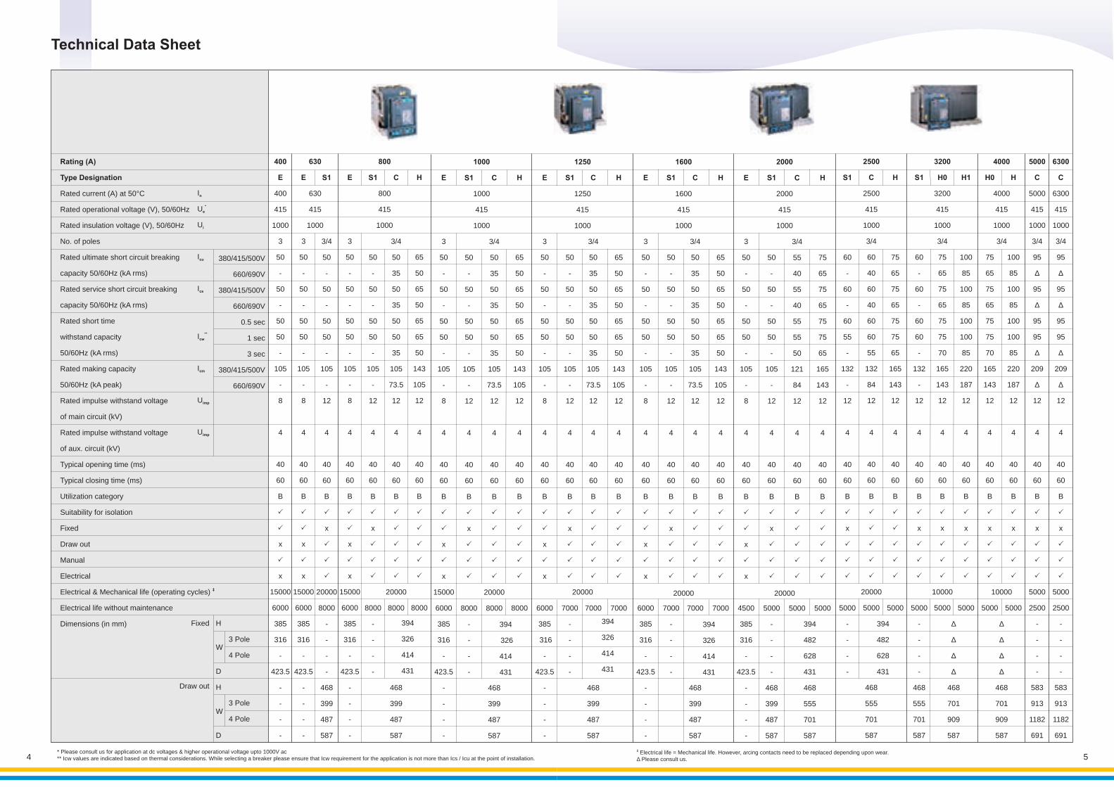
Technical Data Sheet
S1
50
-
50
-
50
50
-
105
-
12
4
40
60
B
P
x
P
P
P
7000
-
-
-
-
C
3/4
50
35
50
35
50
50
35
105
73.5
12
4
40
60
B
P
P
P
P
P
7000
468
399
487
587
H
65
50
65
50
65
65
50
143
105
12
4
40
60
B
7000
P
P
P
P
P
E
3
50
-
50
-
50
50
-
105
-
8
4
40
60
B
6000
385
316
-
423.5
-
-
-
-
P
P
x
P
x
S1
50
-
50
-
50
50
-
105
-
12
4
40
60
B
P
x
P
P
P
7000
-
-
-
-
C
3/4
50
35
50
35
50
50
35
105
73.5
12
4
40
60
B
P
P
P
P
P
7000
468
399
487
587
H
65
50
65
50
65
65
50
143
105
12
4
40
60
B
7000
P
P
P
P
P
E
3
50
-
50
-
50
50
-
105
-
8
4
40
60
B
4500
385
316
-
423.5
-
-
-
-
P
P
x
P
x
C
3/4
55
40
55
40
55
55
50
121
84
12
4
40
60
B
5000
P
P
P
P
P
20000
394
482
628
431
468
555
701
587
S1
50
-
50
-
50
50
-
105
-
12
4
40
60
B
P
x
P
P
P
5000
-
-
-
-
468
399
487
587
2000
2000
415
1000
1250
1250
415
1000
394
326
414
431
20000
394
326
414
431
20000
H
75
65
75
65
75
75
65
165
143
12
4
40
60
B
P
P
P
P
P
5000
1600
1600
415
1000
2500
C
2500
415
1000
3/4
60
40
60
40
60
60
55
132
84
12
4
40
60
B
20000
5000
468
555
701
587
P
P
P
P
P
S1
60
-
60
-
60
55
-
132
-
12
4
40
60
B
P
x
P
P
P
5000
-
-
-
-
H
75
65
75
65
75
75
65
165
143
12
4
40
60
B
5000
P
P
P
P
P
3200
H0
3200
415
1000
3/4
75
65
75
65
75
75
70
165
143
12
4
40
60
B
10000
5000
P
x
P
P
P
S1
60
-
60
-
60
60
-
132
-
12
4
40
60
B
P
x
P
P
P
5000
-
-
-
-
468
555
701
587
H1
100
85
100
85
100
100
85
220
187
12
4
40
60
B
5000
P
x
P
P
P
H0
75
65
75
65
75
75
70
165
143
12
4
40
60
B
5000
P
x
P
P
P
H
100
85
100
85
100
100
85
220
187
12
4
40
60
B
5000
P
x
P
P
P
5000
C
5000
415
1000
3/4
95
∆
95
∆
95
95
∆
209
∆
12
4
40
60
B
5000
2500
-
-
-
-
583
913
1182
691
P
x
P
P
P
6300
C
6300
415
1000
3/4
95
∆
95
∆
95
95
∆
209
∆
12
4
40
60
B
5000
2500
-
-
-
-
583
913
1182
691
P
x
P
P
P
4000
4000
415
1000
3/4
394
482
628
431
∆
∆
∆
∆
468
701
909
587
10000
∆
∆
∆
∆
468
701
909
587
E
3
50
-
50
-
50
50
-
105
-
8
4
40
60
B
15000
6000
385
316
-
423.5
-
-
-
-
P
P
x
P
x
S1
50
-
50
-
50
50
-
105
-
12
4
40
60
B
8000
-
-
-
-
P
x
P
P
P
C
3/4
50
35
50
35
50
50
35
105
73.5
12
4
40
60
B
20000
8000
468
399
487
587
P
P
P
P
P
H
65
50
65
50
65
65
50
143
105
12
4
40
60
B
8000
P
P
P
P
P
E
3
50
-
50
-
50
50
-
105
-
8
4
40
60
B
6000
385
316
-
423.5
-
-
-
-
P
P
x
P
x
1000
1000
415
1000
394
326
414
431
Rating (A)
Type Designation
Rated current (A) at 50°C
Rated operational voltage (V), 50/60Hz
Rated insulation voltage (V), 50/60Hz
No. of poles
Rated ultimate short circuit breaking
capacity 50/60Hz (kA rms)
Rated service short circuit breaking
capacity 50/60Hz (kA rms)
Rated short time
withstand capacity
50/60Hz (kA rms)
Rated making capacity
50/60Hz (kA peak)
Rated impulse withstand voltage
of main circuit (kV)
Rated impulse withstand voltage
of aux. circuit (kV)
Typical opening time (ms)
Typical closing time (ms)
Utilization category
Suitability for isolation
Fixed
Draw out
Manual
Electrical
‡Electrical & Mechanical life (operating cycles)
Electrical life without maintenance
Dimensions (in mm)
380/415/500V
660/690V
380/415/500V
660/690V
0.5 sec
1 sec
3 sec
380/415/500V
660/690V
Fixed
Draw out
400
E
400
415
1000
3
50
-
50
-
50
50
-
105
-
8
4
40
60
B
x
x
15000
6000
385
316
-
423.5
-
-
-
-
P
P
P
E
3
50
-
50
-
50
50
-
105
-
8
4
40
60
B
x
x
15000
6000
385
316
-
423.5
-
-
-
-
P
P
P
S1
3/4
50
-
50
-
50
50
-
105
-
12
4
40
60
B
x
20000
8000
-
-
-
-
468
399
487
587
P
P
P
P
S1
50
-
50
-
50
50
-
105
-
12
4
40
60
B
x
8000
-
-
-
-
P
P
P
P
E
3
50
-
50
-
50
50
-
105
-
8
4
40
60
B
x
x
15000
6000
385
316
-
423.5
-
-
-
-
P
P
P
In
*Ue
Ui
Icu
Ics
**Icw
Icm
Uimp
Uimp
630
630
415
1000
800
800
415
1000
C
3/4
50
35
50
35
50
50
35
105
73.5
12
4
40
60
B
20000
8000
468
399
487
587
P
P
P
P
P
H
65
50
65
50
65
65
50
143
105
12
4
40
60
B
8000
P
P
P
P
P
394
326
414
431
3 Pole
4 Pole
3 Pole
4 Pole
H
W
D
H
W
D
* Please consult us for application at dc voltages & higher operational voltage upto 1000V ac** Icw values are indicated based on thermal considerations. While selecting a breaker please ensure that Icw requirement for the application is not more than Ics / Icu at the point of installation.
‡ Electrical life = Mechanical life. However, arcing contacts need to be replaced depending upon wear.∆ Please consult us.
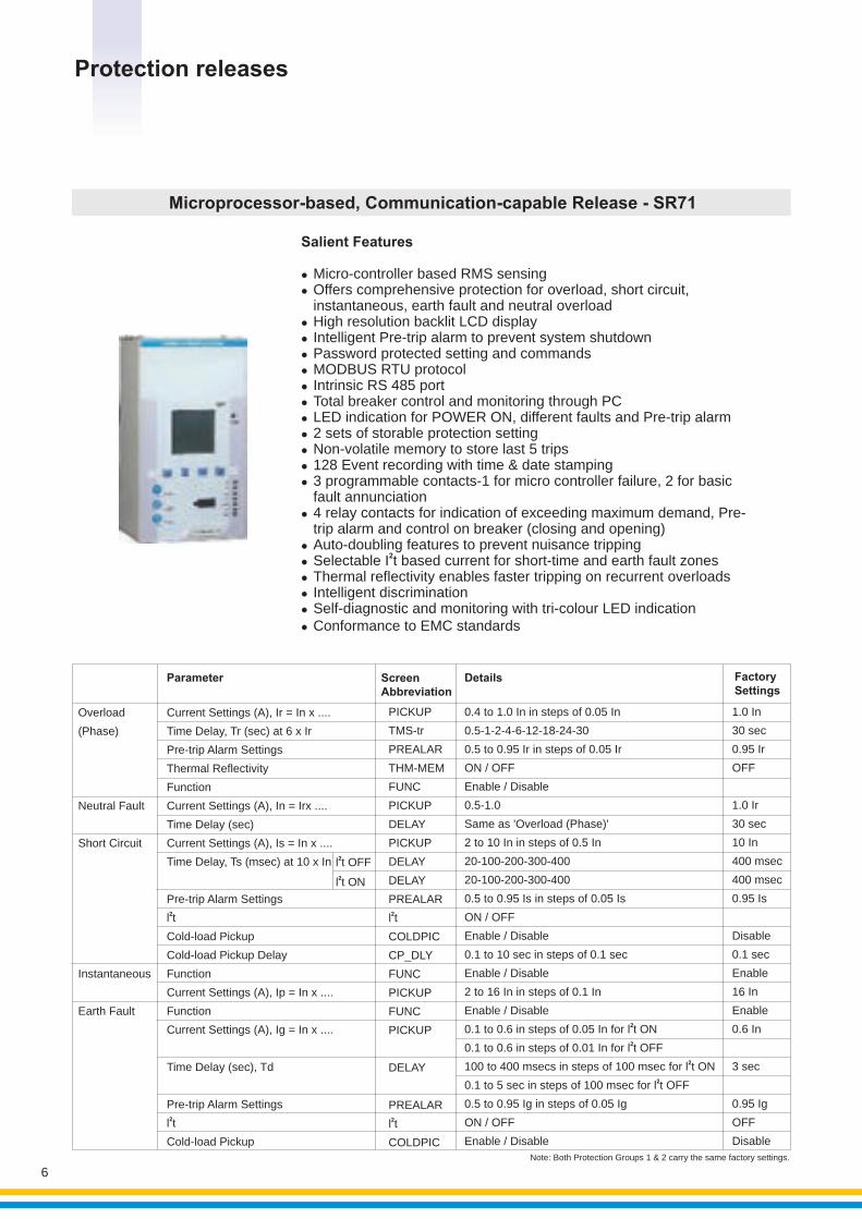
Microprocessor-based, Communication-capable Release - SR71
Salient Features
l
l4 relay contacts for indication of exceeding maximum demand, Pre-trip alarm and control on breaker (closing and opening)
l Micro-controller based RMS sensingl Offers comprehensive protection for overload, short circuit,
instantaneous, earth fault and neutral overloadl High resolution backlit LCD display lIntelligent Pre-trip alarm to prevent system shutdownl Password protected setting and commandsl MODBUS RTU protocoll Intrinsic RS 485 portl Total breaker control and monitoring through PCl LED indication for POWER ON, different faults and Pre-trip alarml 2 sets of storable protection settingl Non-volatile memory to store last 5 tripsl 128 Event recording with time & date stamping 3 programmable contacts-1 for micro controller failure, 2 for basic fault annunciation
l Auto-doubling features to prevent nuisance tripping
2l Selectable I t based current for short-time and earth fault zonesl Thermal reflectivity enables faster tripping on recurrent overloadsl Intelligent discriminationl Self-diagnostic and monitoring with tri-colour LED indicationl Conformance to EMC standards
Protection releases
6
Screen Abbreviation
Details Factory Settings
Parameter
2l t OFF2l t ON
PICKUP
TMS-tr
PREALAR
THM-MEM
FUNC
PICKUP
DELAY
PICKUP
DELAY
DELAY
PREALAR2l t
COLDPIC
CP_DLY
FUNC
PICKUP
FUNC
PICKUP
DELAY
PREALAR2l t
COLDPIC
Current Settings (A), Ir = In x ....
Time Delay, Tr (sec) at 6 x Ir
Pre-trip Alarm Settings
Thermal Reflectivity
Function
Current Settings (A), In = Irx ....
Time Delay (sec)
Current Settings (A), Is = In x ....
Time Delay, Ts (msec) at 10 x In
Pre-trip Alarm Settings2l t
Cold-load Pickup
Cold-load Pickup Delay
Function
Current Settings (A), Ip = In x ....
Function
Current Settings (A), Ig = In x ....
Time Delay (sec), Td
Pre-trip Alarm Settings2l t
Cold-load Pickup
Overload
(Phase)
Neutral Fault
Short Circuit
Instantaneous
Earth Fault
0.4 to 1.0 In in steps of 0.05 In
0.5-1-2-4-6-12-18-24-30
0.5 to 0.95 Ir in steps of 0.05 Ir
ON / OFF
Enable / Disable
0.5-1.0
Same as 'Overload (Phase)'
2 to 10 In in steps of 0.5 In
20-100-200-300-400
20-100-200-300-400
0.5 to 0.95 Is in steps of 0.05 Is
ON / OFF
Enable / Disable
0.1 to 10 sec in steps of 0.1 sec
Enable / Disable
2 to 16 In in steps of 0.1 In
Enable / Disable20.1 to 0.6 in steps of 0.05 In for l t ON20.1 to 0.6 in steps of 0.01 In for l t OFF
2100 to 400 msecs in steps of 100 msec for l t ON20.1 to 5 sec in steps of 100 msec for l t OFF
0.5 to 0.95 Ig in steps of 0.05 Ig
ON / OFF
Enable / Disable
1.0 In
30 sec
0.95 Ir
OFF
1.0 Ir
30 sec
10 In
400 msec
400 msec
0.95 Is
Disable
0.1 sec
Enable
16 In
Enable
0.6 In
3 sec
0.95 Ig
OFF
Disable
Note: Both Protection Groups 1 & 2 carry the same factory settings.
# Requires SR71-PM module
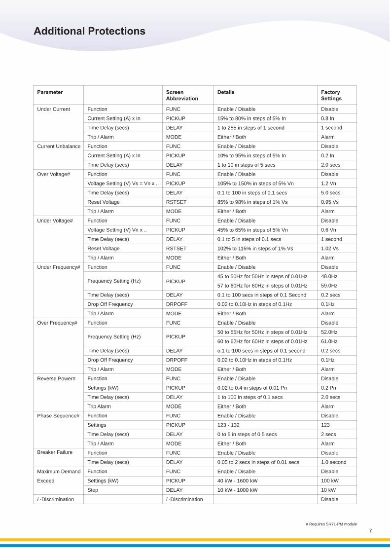
Under Current
Current Unbalance
Over Voltage#
Under Voltage#
Under Frequency#
Over Frequency#
Reverse Power#
Phase Sequence#
Breaker Failure
Maximum Demand
Exceed
i -Discrimination
Function
Current Setting (A) x In
Time Delay (secs)
Trip / Alarm
Function
Current Setting (A) x In
Time Delay (secs)
Function
Voltage Setting (V) Vs = Vn x ..
Time Delay (secs)
Reset Voltage
Trip / Alarm
Function
Voltage Setting (V) Vn x ..
Time Delay (secs)
Reset Voltage
Trip / Alarm
Function
Frequency Setting (Hz)
Time Delay (secs)
Drop Off Frequency
Trip / Alarm
Function
Frequency Setting (Hz)
Time Delay (secs)
Drop Off Frequency
Trip / Alarm
Function
Settings (kW)
Time Delay (secs)
Trip Alarm
Function
Settings
Time Delay (secs)
Trip / Alarm
Function
Time Delay (secs)
Function
Settings (kW)
Step
15% to 80% in steps of 5% In
1 to 255 in steps of 1 second
Either / Both
Enable / Disable
10% to 95% in steps of 5% In
1 to 10 in steps of 5 secs
Enable / Disable
105% to 150% in steps of 5% Vn
0.1 to 100 in steps of 0.1 secs
85% to 98% in steps of 1% Vs
Either / Both
Enable / Disable
45% to 65% in steps of 5% Vn
0.1 to 5 in steps of 0.1 secs
102% to 115% in steps of 1% Vs
Either / Both
Enable / Disable
45 to 50Hz for 50Hz in steps of 0.01Hz
57 to 60Hz for 60Hz in steps of 0.01Hz
0.1 to 100 secs in steps of 0.1 Second
0.02 to 0.10Hz in steps of 0.1Hz
Either / Both
Enable / Disable
50 to 55Hz for 50Hz in steps of 0.01Hz
60 to 62Hz for 60Hz in steps of 0.01Hz
o.1 to 100 secs in steps of 0.1 second
0.02 to 0.10Hz in steps of 0.1Hz
Either / Both
Enable / Disable
0.02 to 0.4 in steps of 0.01 Pn
1 to 100 in steps of 0.1 secs
Either / Both
Enable / Disable
123 - 132
0 to 5 in steps of 0.5 secs
Either / Both
Enable / Disable
0.05 to 2 secs in steps of 0.01 secs
Enable / Disable
40 kW - 1600 kW
10 kW - 1000 kW
Enable / Disable
PICKUP
DELAY
MODE
FUNC
PICKUP
DELAY
FUNC
PICKUP
DELAY
RSTSET
MODE
FUNC
PICKUP
DELAY
RSTSET
MODE
FUNC
PICKUP
DELAY
DRPOFF
MODE
FUNC
PICKUP
DELAY
DRPOFF
MODE
FUNC
PICKUP
DELAY
MODE
FUNC
PICKUP
DELAY
MODE
FUNC
DELAY
FUNC
PICKUP
DELAY
i -Discrimination
FUNC
0.8 In
1 second
Alarm
Disable
0.2 In
2.0 secs
Disable
1.2 Vn
5.0 secs
0.95 Vs
Alarm
Disable
0.6 Vn
1 second
1.02 Vs
Alarm
Disable
48.0Hz
59.0Hz
0.2 secs
0.1Hz
Alarm
Disable
52.0Hz
61.0Hz
0.2 secs
0.1Hz
Alarm
Disable
0.2 Pn
2.0 secs
Alarm
Disable
123
2 secs
Alarm
Disable
1.0 second
Disable
100 kW
10 kW
Disable
Disable
Parameter Screen Abbreviation
Details Factory Settings
Additional Protections
7
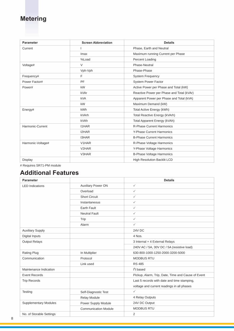
Metering
# Requires SR71-PM module
Current
Voltage#
Frequency#
Power Factor#
Power#
Energy#
Harmonic-Current
Harmonic-Voltage#
Display
Imax
%Load
V
Vph-Vph
F
PF
kW
kVAr
kVA
kW
kWh
kVArh
kVAh
I1HAR
I2HAR
I3HAR
V1HAR
V2HAR
V3HAR
I
Maximum running Current per Phase
Percent Loading
Phase-Neutral
Phase-Phase
System Frequency
System Power Factor
Active Power per Phase and Total (kW)
Reactive Power per Phase and Total (kVAr)
Apparent Power per Phase and Total (kVA)
Maximum Demand (kW)
Total Active Energy (kWh)
Total Reactive Energy (kVArh)
Total Apparent Energy (kVAh)
R-Phase Current Harmonics
Y-Phase Current Harmonics
B-Phase Current Harmonics
R-Phase Voltage Harmonics
Y-Phase Voltage Harmonics
B-Phase Voltage Harmonics
High Resolution Backlit LCD
Phase, Earth and Neutral
Screen AbbreviationParameter Details
LED Indications
Auxiliary Supply
Digital Inputs
Output Relays
Rating Plug
Communication
Maintenance Indication
Event Records
Trip Records
Testing
Supplementary Modules
No. of Storable Settings
Auxiliary Power ON
Overload
Short Circuit
Instantaneous
Earth Fault
Neutral Fault
Trip
Alarm
In Multiplier
Protocol
Link used
Self-Diagnostic Test
Relay Module
Power Supply Module
Communication Module
Parameter
24V DC
4 Nos.
3 Internal + 4 External Relays
240V AC / 5A, 30V DC / 5A (resistive load)
630-800-1000-1250-2000-3200-5000
MODBUS RTU
RS 485
2I t based
Pickup, Alarm, Trip, Date, Time and Cause of Event
Last 5 records with date and time stamping,
voltage and current readings in all phases
4 Relay Outputs
24V DC Output
MODBUS RTU
2
P
P
P
P
P
P
P
P
P
Details
Additional Features
8
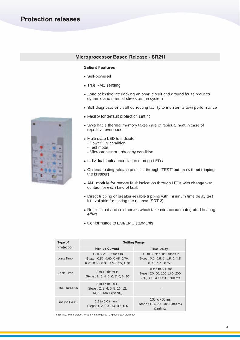
Salient Features
lSelf-powered
lTrue RMS sensing
lZone selective interlocking on short circuit and ground faults reduces dynamic and thermal stress on the system
lSelf-diagnostic and self-correcting facility to monitor its own performance
lFacility for default protection setting
lSwitchable thermal memory takes care of residual heat in case of repetitive overloads
lMulti-state LED to indicate - Power ON condition
- Test mode - Microprocessor unhealthy condition
lIndividual fault annunciation through LEDs
lOn load testing release possible through ‘TEST’ button (without tripping the breaker)
lAN1 module for remote fault indication through LEDs with changeover contact for each kind of fault
lDirect tripping of breaker-reliable tripping with minimum time delay test kit available for testing the release (SRT-2)
lRealistic hot and cold curves which take into account integrated heating effect
lConformance to EMI/EMC standards
Microprocessor Based Release - SR21i
In 3 phase, 4 wire system, Neutral CT is required for ground fault protection.
Protection releases
Type of
Protection
Long Time
Short Time
Instantaneous
Ground Fault
Ir - 0.5 to 1.0 times In
Steps : 0.50, 0.60, 0.65, 0.70,
0.75, 0.80, 0.85, 0.9, 0.95, 1.00
2 to 10 times In
Steps : 2, 3, 4, 5, 6, 7, 8, 9, 10
2 to 16 times In
Steps : 2, 3, 4, 6, 8, 10, 12,
14, 16, MAX (infinity)
0.2 to 0.6 times In
Steps : 0.2, 0.3, 0.4, 0.5, 0.6
0.2 to 30 sec. at 6 times Ir
Steps : 0.2, 0.5, 1, 1.5, 2, 3.5,
6, 12, 17, 30 Sec
20 ms to 600 ms
Steps : 20, 60, 100, 160, 200,
260, 300, 400, 500, 600 ms
-
100 to 400 ms
Steps : 100, 200, 300, 400 ms
& infinity
Pick-up Current Time Delay
Setting Range
9
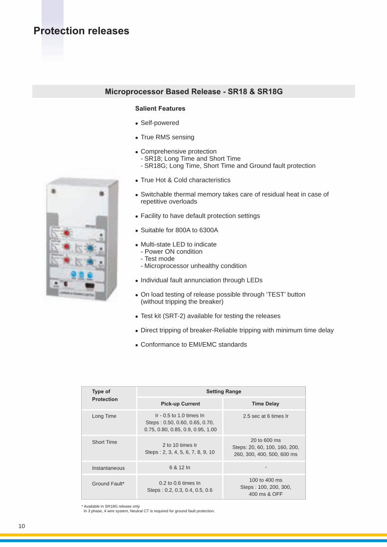
Microprocessor Based Release - SR18 & SR18G
* Available in SR18G release only In 3 phase, 4 wire system, Neutral CT is required for ground fault protection.
Salient Features
lSelf-powered
lTrue RMS sensing
lComprehensive protection- SR18; Long Time and Short Time- SR18G; Long Time, Short Time and Ground fault protection
lTrue Hot & Cold characteristics
lSwitchable thermal memory takes care of residual heat in case ofrepetitive overloads
lFacility to have default protection settings
lSuitable for 800A to 6300A
lMulti-state LED to indicate - Power ON condition - Test mode - Microprocessor unhealthy condition
lIndividual fault annunciation through LEDs
lOn load testing of release possible through ‘TEST’ button (without tripping the breaker)
lTest kit (SRT-2) available for testing the releases
lDirect tripping of breaker-Reliable tripping with minimum time delay
lConformance to EMI/EMC standards
Protection releases
10
Long Time
Short Time
Instantaneous
Ground Fault*
Ir - 0.5 to 1.0 times In
Steps : 0.50, 0.60, 0.65, 0.70,
0.75, 0.80, 0.85, 0.9, 0.95, 1.00
2 to 10 times Ir
Steps : 2, 3, 4, 5, 6, 7, 8, 9, 10
6 & 12 In
0.2 to 0.6 times In
Steps : 0.2, 0.3, 0.4, 0.5, 0.6
Pick-up Current Time Delay
Setting Range
2.5 sec at 6 time s Ir
20 to 600 ms
Steps : 20, 60, 100, 160, 200,
260 , 300, 400, 500, 600 ms
-
100 to 400 ms
Steps : 100, 200, 300,
400 ms & OFF
Type of
Protection
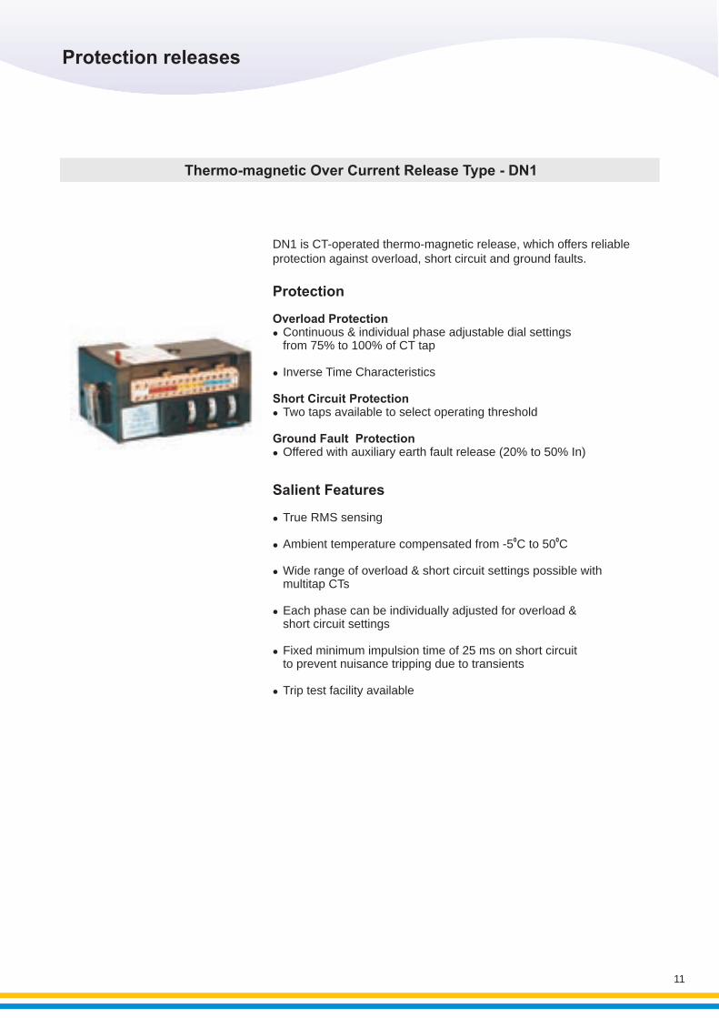
DN1 is CT-operated thermo-magnetic release, which offers reliable protection against overload, short circuit and ground faults.
Thermo-magnetic Over Current Release Type - DN1
Protection
Overload ProtectionlContinuous & individual phase adjustable dial settings
from 75% to 100% of CT tap
lInverse Time Characteristics
Short Circuit ProtectionlTwo taps available to select operating threshold
Ground Fault ProtectionlOffered with auxiliary earth fault release (20% to 50% In)
Protection releases
11
Salient Features
lTrue RMS sensing
0 0lAmbient temperature compensated from -5 C to 50 C
lWide range of overload & short circuit settings possible with multitap CTs
lEach phase can be individually adjusted for overload & short circuit settings
lFixed minimum impulsion time of 25 ms on short circuit to prevent nuisance tripping due to transients
lTrip test facility available
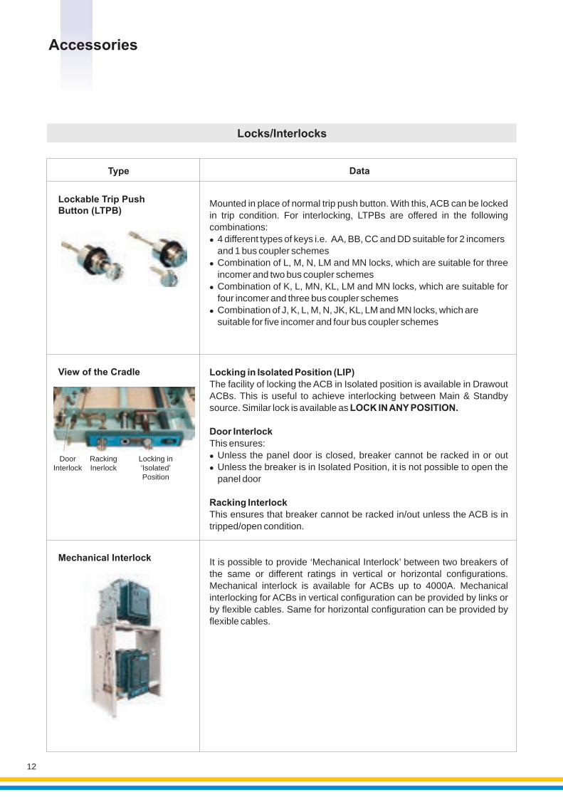
Locks/Interlocks
It is possible to provide ‘Mechanical Interlock’ between two breakers of the same or different ratings in vertical or horizontal configurations. Mechanical interlock is available for ACBs up to 4000A. Mechanical interlocking for ACBs in vertical configuration can be provided by links or by flexible cables. Same for horizontal configuration can be provided by flexible cables.
Mechanical Interlock
Mounted in place of normal trip push button. With this, ACB can be locked in trip condition. For interlocking, LTPBs are offered in the following combinations:l4 different types of keys i.e. AA, BB, CC and DD suitable for 2 incomers
and 1 bus coupler schemeslCombination of L, M, N, LM and MN locks, which are suitable for three incomer and two bus coupler schemeslCombination of K, L, MN, KL, LM and MN locks, which are suitable for
four incomer and three bus coupler schemeslCombination of J, K, L, M, N, JK, KL, LM and MN locks, which are
suitable for five incomer and four bus coupler schemes
Lockable Trip Push Button (LTPB)
Type
Locking in Isolated Position (LIP)The facility of locking the ACB in Isolated position is available in Drawout ACBs. This is useful to achieve interlocking between Main & Standby source. Similar lock is available as LOCK IN ANY POSITION.
Door InterlockThis ensures:lUnless the panel door is closed, breaker cannot be racked in or outlUnless the breaker is in Isolated Position, it is not possible to open the
panel door
Racking InterlockThis ensures that breaker cannot be racked in/out unless the ACB is in tripped/open condition.
DoorInterlock
RackingInerlock
Locking in‘Isolated’Position
View of the Cradle
Data
Accessories
12
Signaling
DataType
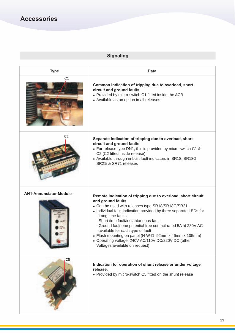
Separate indication of tripping due to overload, short circuit and ground faults.
For release type DN1, this is provided by micro-switch C1 & C2 (C2 fitted inside release)Available through in-built fault indicators in SR18, SR21i & SR71 releases
l
l SR18G,
C2
Remote indication of tripping due to overload, short circuit and ground faults.l
lIndividual fault indication provided by three separate LEDs for - Long time faults - Short time fault/instantaneous fault - Ground fault one potential free contact rated 5A at 230V AC
available for each type of faultlFlush mounting on panel (H-W-D=92mm x 46mm x 105mm)lOperating voltage: 240V AC/110V DC/220V DC (other
Voltages available on request)
Can be used with releases type SR18/SR18G/SR21i
AN1-Annunciator Module
C5
Indication for operation of shunt release or under voltage release.
Provided by micro-switch C5 fitted on the shunt release l
Common indication of tripping due to overload, short circuit and ground faults.
Provided by micro-switch C1 fitted inside the ACB Available as an option in all releases
l
l
C1
Accessories
13
Accessories
14
Control
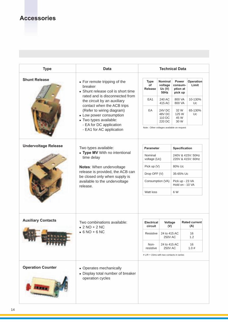
Two types available:l With no intentional
time delay
Notes: When undervoltagerelease is provided, the ACB can be closed only when supply isavailable to the undervoltagerelease.
Type MV
Data
l
breakerlShunt release coil is short time
rated and is disconnected from the circuit by an auxiliary contact when the ACB trips (Refer to wiring diagram)
lLow power consumptionl Two types available: - EA for DC application - EA1 for AC application
For remote tripping of the Shunt Release
Undervoltage Release
Two combinations available:l2 NO + 2 NCl6 NO + 6 NC
Auxiliary Contacts
l
lDisplay total number of breaker operation cycles
Operates mechanicallyOperation Counter
Electricalcircuit
Resistive
Non-resistive
Voltage(V)
Rated current (A)
# L/R = 15ms with two contacts in series
Type
Typeof
Release
NominalvoltageUc (V)50Hz
Powerconsum-ption at pick up
Operation Limit
EA1
EA
240 A415 AC
24V DC48V DC110 DC220 DC
C 800 VA800 VA
32 W125 W45 W30 W
Note : Other voltages available on request
10-130%Uc
65-130%Uc
Technical Data
Nominalvoltage (Uc)
Pick up (V)
Drop OFF (V)
Consumption
Watt loss
(VA)
240V & 415V: 50Hz220V & 415V: 60Hz
80% Uc
35-65% Uc
Pick up - 23 VAHold on - 10 VA
6 W
Parameter Specification
161.2
161.0 #
24 to 415 AC250V AC
24 to 415 AC250V AC
Overall Dimensions
15
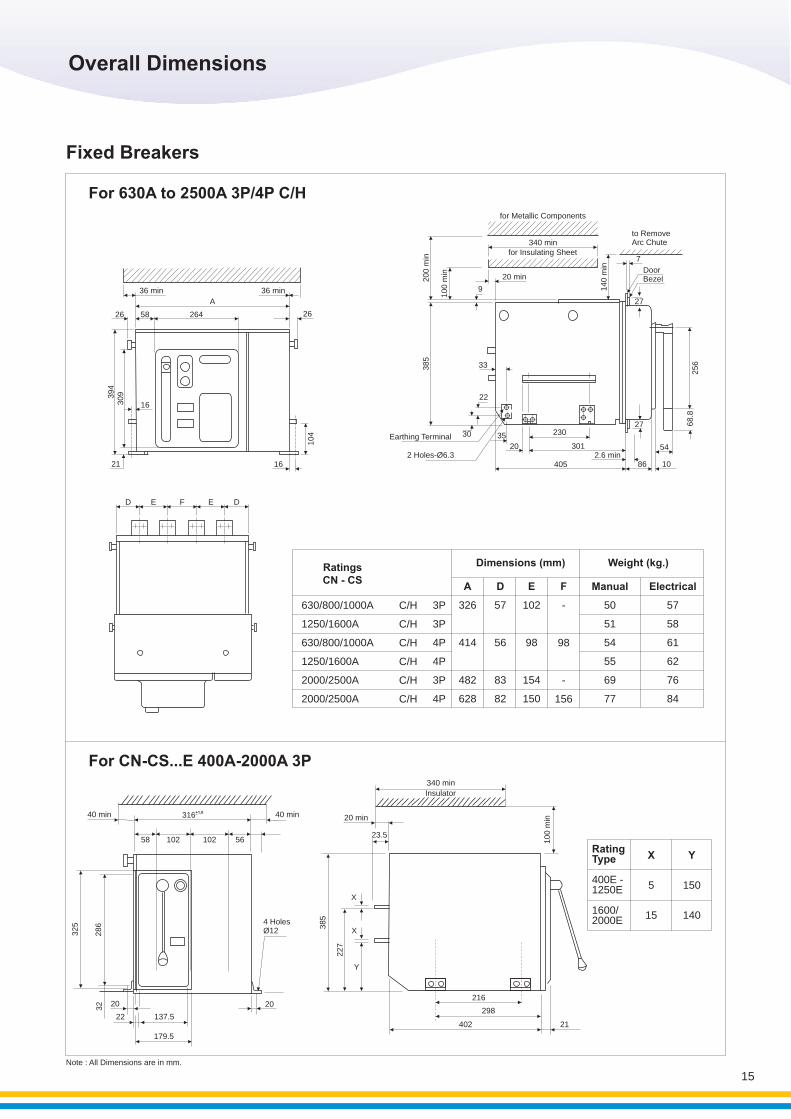
Weight (kg.)Dimensions (mm)RatingsCN - CS
A
326
414
482
628
D
57
56
83
82
E
102
98
154
150
F
-
98
-
156
630/800/1000A
1250/1600A
630/800/1000A
1250/1600A
2000/2500A
2000/2500A
3P
3P
4P
4P
3P
4P
Manual
50
51
54
55
69
77
Electrical
57
58
61
62
76
84
C/H
C/H
C/H
C/H
C/H
C/H
Rating Type
400E -1250E
1600/2000E
X
5
15
Y
150
140
for Metallic Components
to RemoveArc Chute
DoorBezel2
00 m
in
100 m
in
9
340 min
20 min
for Insulating Sheet
140 m
in
7
27
385
33
22
30 35
20
230
301
4052.6 min
86
27
54
10
68.8
256
Earthing Terminal
2 Holes 6.3-Ø
FE DD E
For 630A to 2500A 3P/4P C/H
Note : All Dimensions are in mm.
36 min 36 min
A
26 58 264 26
16309394
21 16
10
4
40 min 40 min+1.0316
58 102 102 56
325
286
20
22 137.5
179.5
32 20
4 HolesØ12
385
X
X
Y
227
20 min
23.5
340 min
Insulator
100 m
in
216
298
402 21
For CN-CS...E 400A-2000A 3P
Fixed Breakers
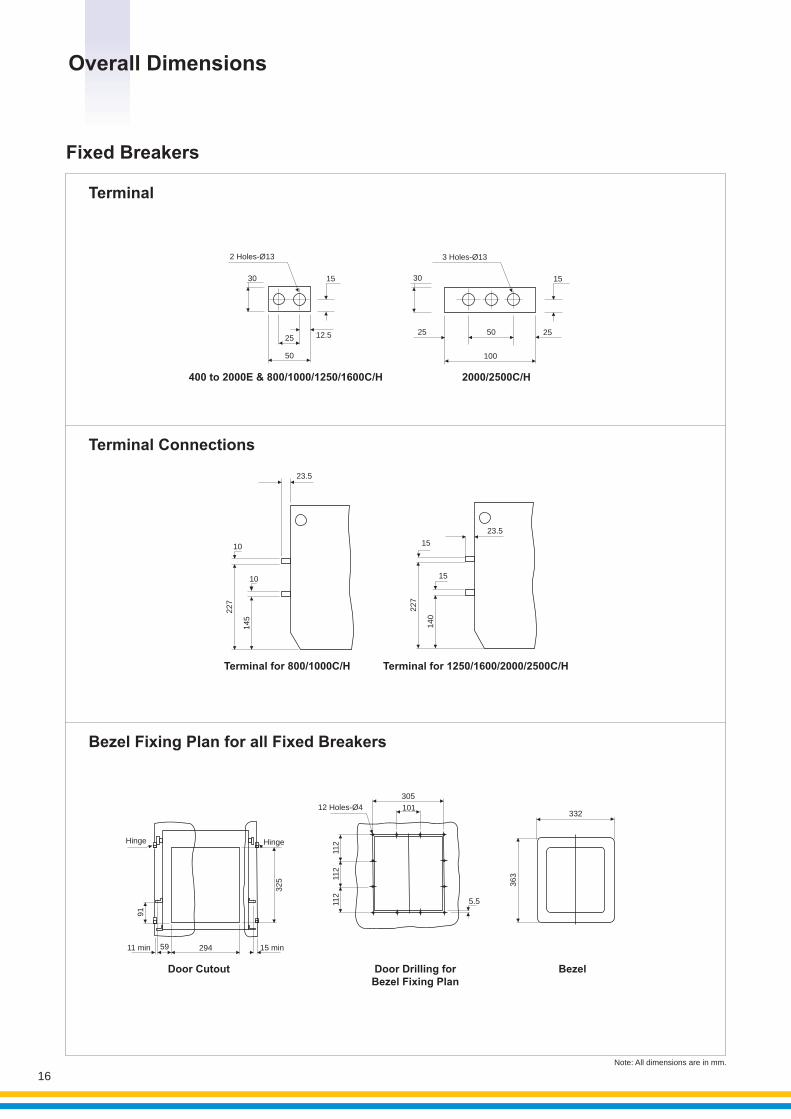
Bezel Fixing Plan for all Fixed Breakers
Bezel
332
363
Door Drilling forBezel Fixing Plan
Door Cutout
Hinge
325
91
11 min 59 294 15 min
Hinge
Terminal for 1250/1600/2000/2500C/H
15
15
227
140
23.5
Terminal
400 to 2000E & 800/1000/1250/1600C/H
30 15
12.525
50
2 Holes- 13Ø
2000/2500C/H
30 15
2525 50
100
3 Holes- 13Ø
Terminal for 800/1000C/H
10
10
227
145
23.5
5.5
305
10112 Holes- 4Ø
112
112
112
Note: All dimensions are in mm.
Terminal Connections
Overall Dimensions
16
Fixed Breakers
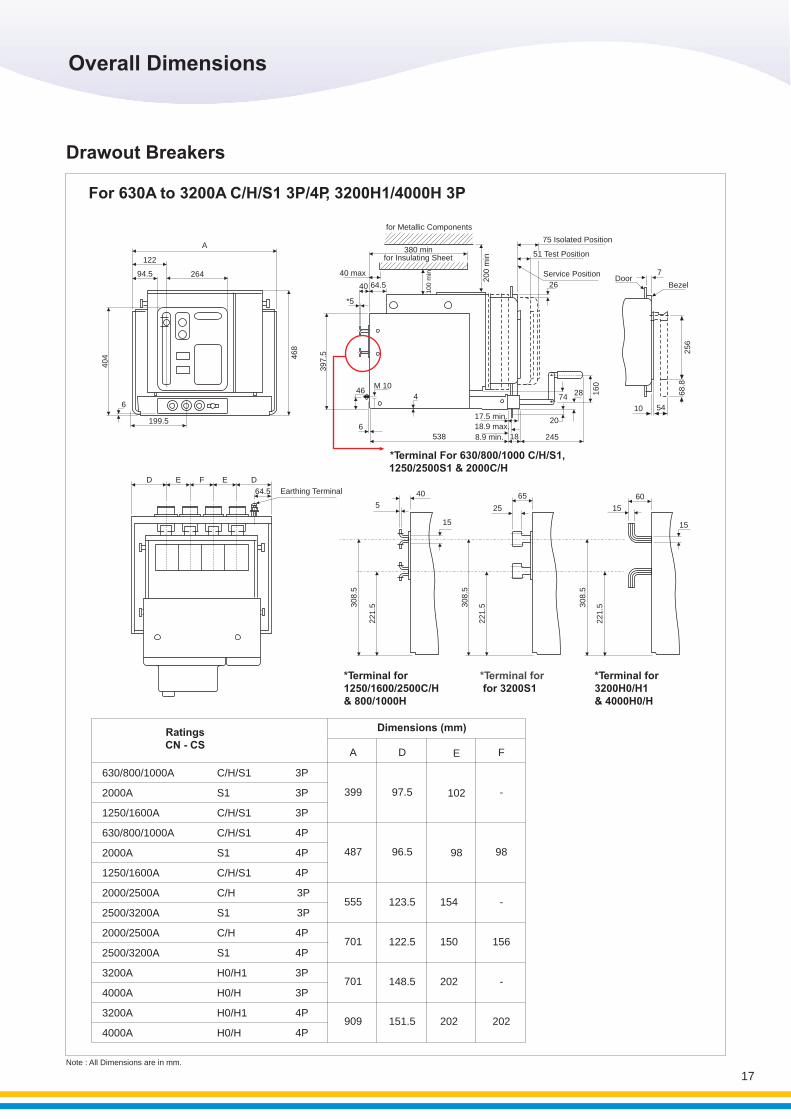
For 630A to 3200A C/H/S1 3P/4P, 3200H1/4000H 3P
A
122
26494.5
404
6
199.5
468
D E F E D
64.5 Earthing Terminal
*Terminal For 630/800/1000 C/H/S1, 1250/2500S1 & 2000C/H
for Metallic Components
for Insulating Sheet380 min
40 max
40 64.5
*5
397.5
46M 10
4
6538
10
0 m
in
DoorBezel
Service Position
51 Test Position
75 Isolated Position
17.5 min.
18.9 max.
8.9 min. 18 245
20
7428 1
60
26
200 m
in
7
10 54
68.8
256
*Terminal for for 3200S1
25
65
*Terminal for1250/1600/2500C/H& 800/1000H
5
40
15
308.5
221.5
221.53
08.5
*Terminal for3200H0/H1 & 4000H0/H
15
15
221.53
08.5
60
Dimensions (mm)RatingsCN - CS
630/800/1000A
2000A
1250/1600A
630/800/1000A
2000A
1250/1600A
2000/2500A
2500/3200A
2000/2500A
2500/3200A
3200A
4000A
3200A
4000A
3P
3P
4P
4P
3P
4P
3P
3P
4P
4P
3P
4P
3P
4P
A
399
487
D
97.5
96.5
E
102
98
F
-
98
C/H/S1
S1
C/H/S1
S1
C/H
S1
C/H
S1
H0/H1
H0/H
H0/H1
H0/H
C/H/S1
C/H/S1
Note : All Dimensions are in mm.
555
701
701
909
123.5
122.5
148.5
151.5
154
150
202
202
-
156
-
202
Overall Dimensions
17
Drawout Breakers
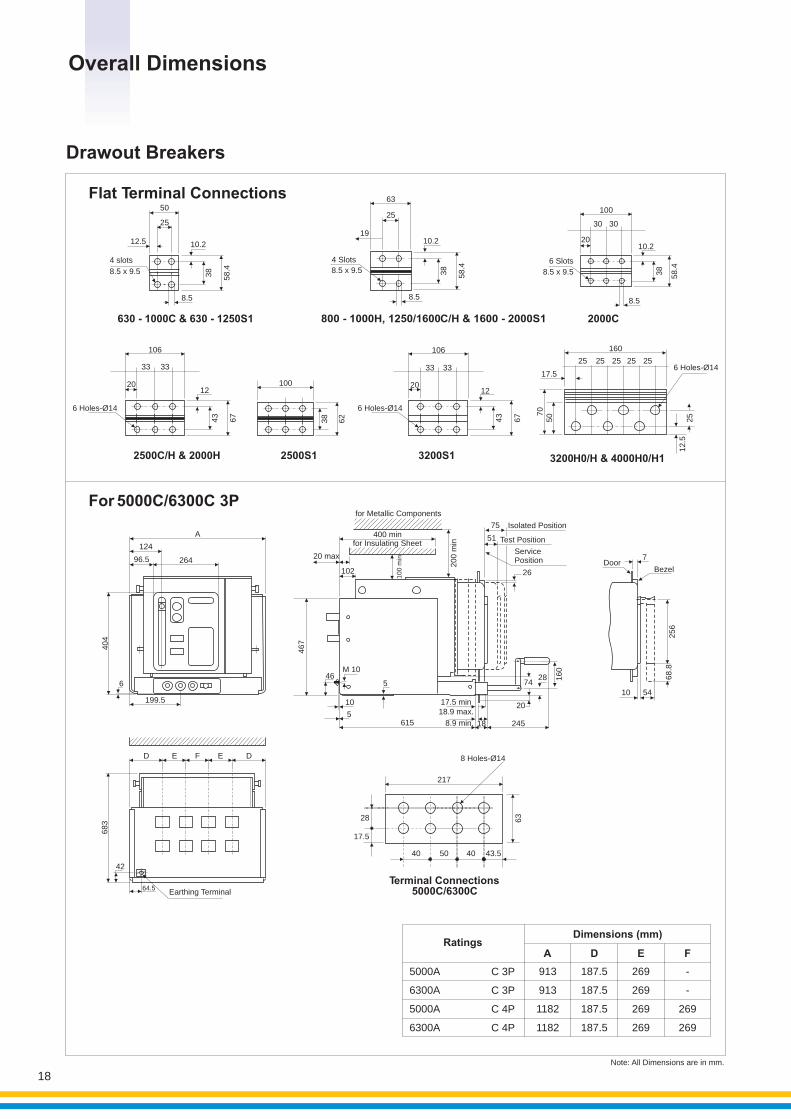
Note: All Dimensions are in mm.
Flat Terminal Connections
630 - 1000C & 630 - 1250S1 2000C
2500C/H & 2000H 2500S1
For 5000C/6300C 3P
A
124
96.5 264
6
199.5
404
DoorBezel
10 54
68.8
256
7
D E F E D
683
42
64.5Earthing Terminal
20
106
3333
43
67
12
6 Holes- 14Ø
20
106
3333
43
67
12
6 Holes 14-Ø
38
62
12.5
4 slots
8.5 x 9.5
25
10.2
38
58.4
8.5
50
6 Holes 14-Ø
160
25 25 25 25 25
17.5
25
507
0
12.5
Terminal Connections5000C/6300C
28
17.5
40 50 40 43.5
63
217
8 Holes- 14Ø
19
63
4 Slots
8.5 x 9.5
25
10.2
38
58.4
8.5
800 - 1000H, 1250/1600C/H & 1600 - 2000S1
6 Slots
8.5 x 9.5
100
30
38
58.4
10.2
8.5
30
20
3200S1 3200H0/H & 4000H0/H1
for Metallic Components
400 minfor Insulating Sheet
Service Position
Test Position
Isolated Position
20 max
102
100 m
in
200 m
in
467
46M 10
10
5
5
615
17.5 min18.9 max.
8.9 min. 18 245
20
7428 1
60
26
75
51
Overall Dimensions
18
A D E
5000A
6300A
5000A
6300A
C 3P
C 3P
C 4P
C 4P
913
913
1182
1182
187.5
187.5
187.5
187.5
269
269
269
269
F
-
-
269
269
RatingsDimensions (mm)
100
Drawout Breakers
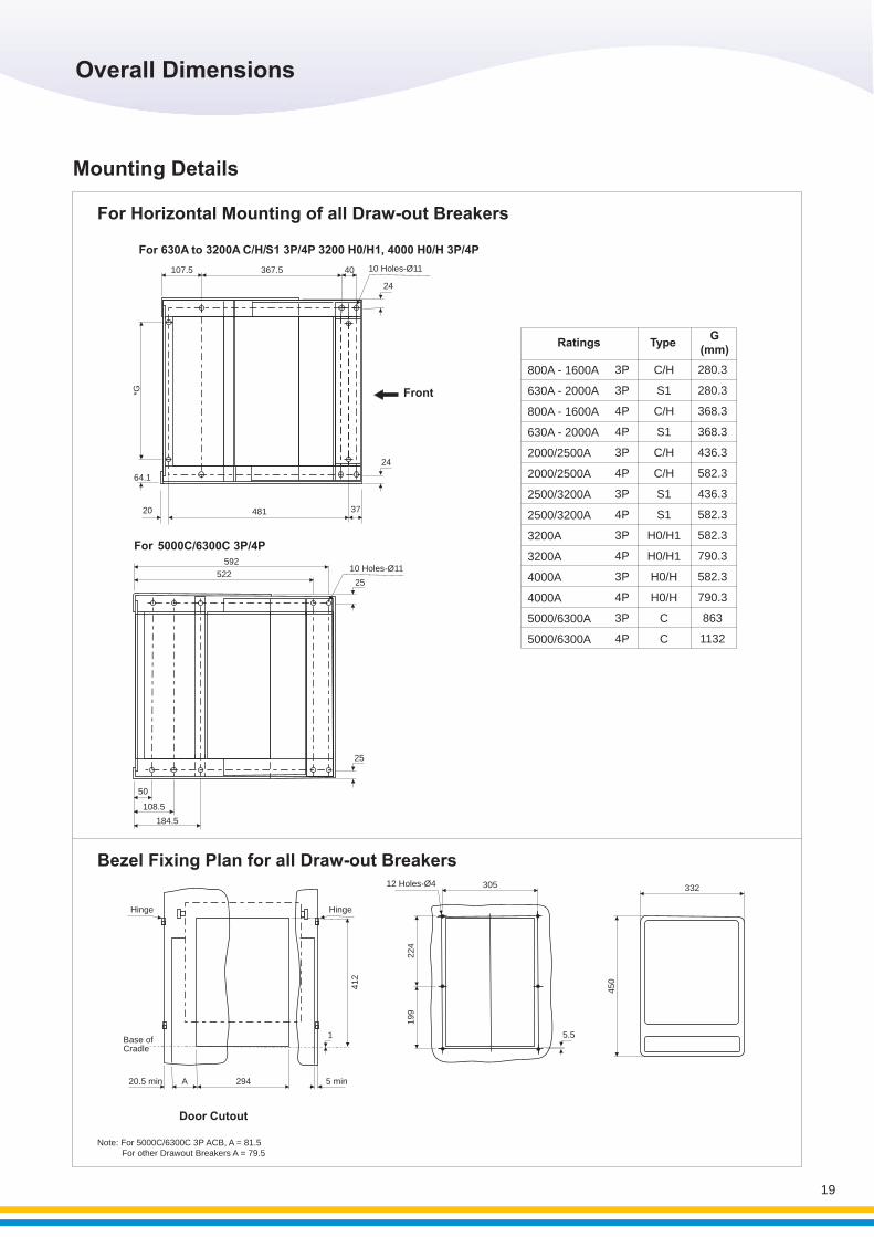
For Horizontal Mounting of all Draw-out Breakers
Bezel Fixing Plan for all Draw-out Breakers
For 5000C/6300C 3P/4P
25
50
108.5
184.5
25
10 Holes- 11Ø592
522
Door Cutout
Hinge
A20.5 min 294 5 min
Hinge
Base ofCradle
1
412
5.5
12 Holes- 4Ø
199
224
305 332
450
37
24
Front
48120
64.1
*G
107.5 367.5 40
24
10 Holes- 11Ø
For 630A to 3200A C/H/ S1 3P/4P 3200 H0/H1, 4000 H0/H 3P/4P
Overall Dimensions
19
Note: For 5000C/6300C 3P ACB, A = 81.5 For other Drawout Breakers A = 79.5
800A - 1600A
630A - 2000A
800A - 1600A
630A - 2000A
2000 / 2500A
2000 / 2500A
2500 / 3200A
2500 / 3200A
3200A
3200A
4000A
4000A
5000 / 6300A
5000/ 6300A
3P
3P
4P
4P
3P
4P
3P
4P
3P
4P
3P
4P
3P
4P
C/H
S1
C/H
S1
C/H
C/H
S1
S1
H0 / H1
H0 / H1
H0 / H
H0 / H
C
C
280.3
280.3
368.3
368.3
436.3
582.3
436.3
582.3
582.3
790.3
582.3
790.3
863
1132
RatingsG
(mm)Type
Mounting Details
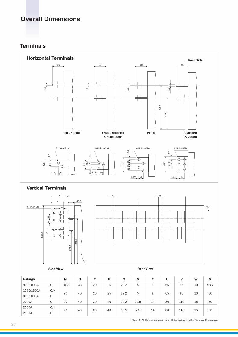
Note : 1) All Dimensions are in mm. 2) Consult us for other Terminal Orientations.
Horizontal Terminals
800 - 1000C 1250 - 1600C/H& 800/1000H
2000C 2500C/H& 2000H
80 80 80
1510
10
15
308.5
221.5
80
Rear Side
25
25
25
12.5 25
100
12.5
4 Holes 14-Ø 6 Holes 14-Ø
20
160 3
333
12 43
12.5
12.5
50
25
25
2 Holes- 14Ø
Side View Rear View
V
U
O P4 Holes T-Ø
NM
40.0
R
387
.5 X
221.5
308.5
S W
Ratings M N P Q R S T U V W X
800/1000A
1250/1600A
800/1000A
2000A
2500A
2000A
C
C/H
H
C
C/H
H
10.2
20
20
20
38
40
40
40
20
20
20
20
25
25
40
40
29.2
29.2
29.2
33.5
5
5
22.5
7.5
9
9
14
14
65
65
80
80
95
95
110
110
10
10
15
15
58.4
80
80
80
63
3 Holes 14-Ø
15
16.5
12.5 30
16.5
Top
Vertical Terminals
Overall Dimensions
20
Terminals

‘Train & Gain’ - This concept underlies L&T’s commitment to its customers and the Indian switchgear industry. To this end, L&T has set up Switchgear Training Centers equipped with a wide range of education facilities at Pune, Lucknow & Coonoor. Specially designed ‘Hands-On’ training programs on the operation & maintenance of switchgear are conducted for engineers and technicians from different industry segments. The centers have state-of-the-art training facilities,well-equipped workshops and testing systems.
Pune Lucknow
Coonoor
Switchgear Training Centres
21


![GORE Joint Sealant DF · DF07 7 PPP10-17 DF10 10 PPP17-25 DF14 14 PPP25-40 DF17 17 PP P 40-50 DF20 20 PP P 50-65 DF25 25 PP 65+ For Effective Sealing Width [mm] * Not supplied with](https://img.pdfslide.net/doc/110x75/5f470d5336034b6cd4545c1c/gore-joint-sealant-df-df07-7-ppp10-17-df10-10-ppp17-25-df14-14-ppp25-40-df17-17.jpg)