Embed Size (px)
Citation preview
Air Condition Power Systems There is little standardization for air condition systems for railways. Each class of train has some unique requirements for air conditioning. The systems may be mounted under frame or mounted in the side of locomotives or quite commonly roof-mounted in passenger cars and locomotives. Though they may look different, the principles of air condition systems are consistent and most systems use common basic components.
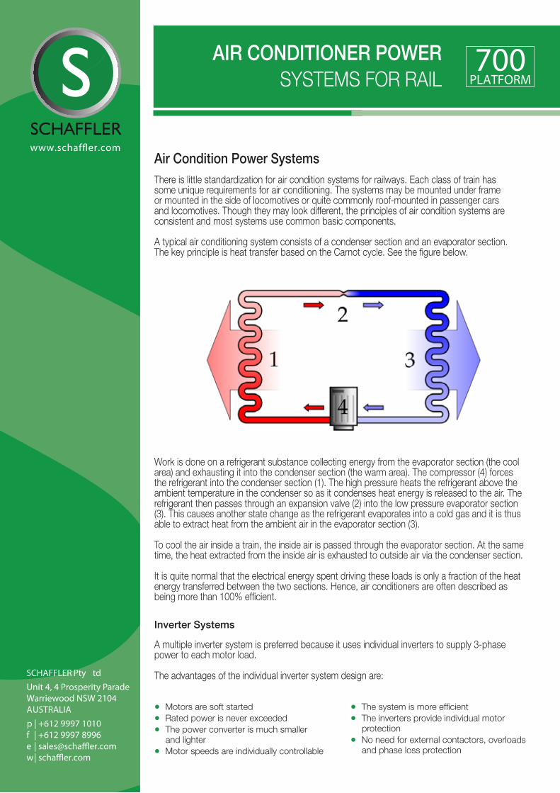
A typical air conditioning system consists of a condenser section and an evaporator section. The key principle is heat transfer based on the Carnot cycle. See the figure below.
AIR CONDITIONER POWER SYSTEMS FOR RAIL
Work is done on a refrigerant substance collecting energy from the evaporator section (the cool area) and exhausting it into the condenser section (the warm area). The compressor (4) forces the refrigerant into the condenser section (1). The high pressure heats the refrigerant above the ambient temperature in the condenser so as it condenses heat energy is released to the air. The refrigerant then passes through an expansion valve (2) into the low pressure evaporator section (3). This causes another state change as the refrigerant evaporates into a cold gas and it is thus able to extract heat from the ambient air in the evaporator section (3).
To cool the air inside a train, the inside air is passed through the evaporator section. At the same time, the heat extracted from the inside air is exhausted to outside air via the condenser section.
It is quite normal that the electrical energy spent driving these loads is only a fraction of the heat energy transferred between the two sections. Hence, air conditioners are often described as being more than 100% efficient.
• Motors are soft started• Rated power is never exceeded• The power converter is much smaller
and lighter• Motor speeds are individually controllable
• The system is more efficient• The inverters provide individual motor
protection• No need for external contactors, overloads
and phase loss protection
Inverter Systems A multiple inverter system is preferred because it uses individual inverters to supply 3-phase power to each motor load. The advantages of the individual inverter system design are:

Because the motors are soft started, there is no inrush current. This means that the rated power is never exceeded and the front-end power converter can be smaller. The inverters operate off the overhead ac catenary, 3rd rail or locomotive battery supply.
Variable frequency inverters facilitate speed control of the motors so the system can maintain temperature in a more efficient manner than simply turning motors on or off. The inverters are able to be programmed with the individual specifications of each motor and can detect when a motor has been overloaded or lost a phase. In this way the inverters also act as a motor protection device.
Schaffler air con inverters provide “Cycle by Cycle Current Limiting” at the switching frequency so if a single inverter is preferred, then the inverter will take care of direct-on-line starting and limit high inrush starting current.
Single Inverter Systems
Air Conditioner Power Systems
Input 74V DC, 110V DC locomotive battery voltage600V Vdc or 750V Vdc 3rd rail or catenary25 kV, 15 kV, 50 or 60 or 16⅔Hz catenary380 Vac, 415 Vac, 440 Vac or 480 Vac 3-phase auxiliary generator
Output 380 Vac, 415Vac, 440 Vac or 480 Vac 3-phase variable frequency Optional 220 Vac or 240 Vac 1-phase for fans Individual fan motor / compressor motor control
Air conditioners used on locomotives, EMUs and DMUs use two 3-phase inverters systems. One for the compressor plus the evaporator fan and one for the condenser fan. The inverter driving the compressor can be speed controlled and can operate above 50 or 60 Hz. In some installations the fans are driven from 1-phase ac.
Locomotive Air Conditioner Systems Enclosure intended for fitting in the switch room of the locomotive. System includes DCformer (72 Vdc to 700 Vdc) one 5.5 kW inverter + 2.2 kW inverter.
Underframe mounting of Power System The enclosure for underframe mounting is divided such that the input converter (DCformer or Cycloverter) is fitted to the back heatsink and the inverters are fitted to the front door heatsink. The enclosure is IP66. All Schaffler products are supplied with military style plugs and mating cable plugs are provided.
Multiple Inverter Systems
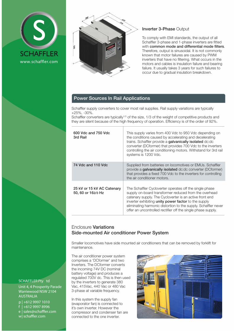
Inverter 3-Phase Output To comply with EMI standards, the output of all Schaffler 3-phase and 1-phase inverters are fitted with common mode and differential mode filters. Therefore, output is sinusoidal. It is not commonly known that motor failures are caused by PWM inverters that have no filtering. What occurs in the motors and cables is insulation failure and bearing failure. It usually takes 3 years for such failures to occur due to gradual insulation breakdown.
Power Sources In Rail Applications
600 Vdc and 750 Vdc 3rd Rail
This supply varies from 400 Vdc to 950 Vdc depending on the conditions caused by accelerating and decelerating trains. Schaffler provide a galvanically isolated dc:dc converter (DCformer) that provides 700 Vdc to the inverters controlling the air conditioning motors. Withstand for 3rd rail systems is 1200 Vdc.
74 Vdc and 110 Vdc Supplied from batteries on locomotives or EMUs. Schaffler provide a galvanically isolated dc:dc converter (DCformer) that provides a fixed 700 Vdc to the inverters for controlling the air conditioner motors.
25 kV or 15 kV AC Catenary 50, 60 or 162/3 Hz
The Schaffler Cycloverter operates off the single phase supply on-board transformer reduced from the overhead catenary supply. The Cycloverter is an active front end inverter exhibiting unity power factor to the supply eliminating harmonic distortion to the supply. Schaffler never offer an uncontrolled rectifier off the single phase supply.
Schaffler supply converters to cover most rail supplies. Rail supply variations are typically +25%, -30%.Schaffler converters are typically1/3 of the size, 1/3 of the weight of competitive products and they are silent because of the high frequency of operation. Efficiency is of the order of 92%.
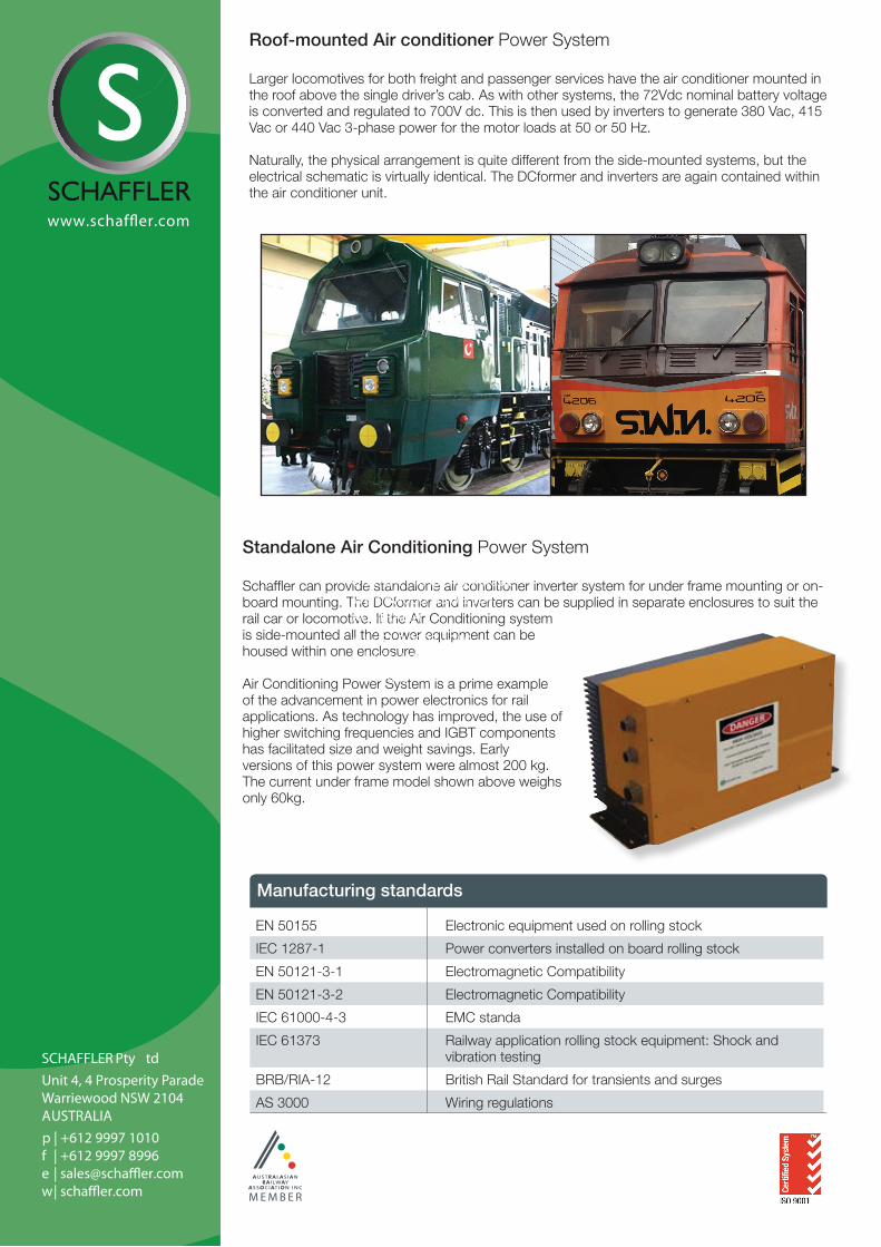
Enclosure Variations Side-mounted Air conditioner Power System Smaller locomotives have side mounted air conditioners that can be removed by forklift for maintenance.
The air conditioner power system comprises a ‘DCformer’ and two Inverters. The DCformer converts the incoming 74V DC (nominal battery voltage) and produces a regulated 700V dc. This is then used by the inverters to generate 380 Vac, 415Vac, 440 Vac or 480 Vac 3-phase at variable frequency.
In this system the supply fan (evaporator fan) is connected to it’s own inverter. However the compressor and condenser fan are connected to the one inverter.
Standalone Air Conditioning Power System Schaffler can provide standalone air conditioner inverter system for under frame mounting or on-board mounting. The DCformer and inverters can be supplied in separate enclosures to suit the rail car or locomotive. If the Air Conditioning system is side-mounted all the power equipment can be housed within one enclosure. Air Conditioning Power System is a prime example of the advancement in power electronics for rail applications. As technology has improved, the use of higher switching frequencies and IGBT components has facilitated size and weight savings. Early versions of this power system were almost 200 kg. The current under frame model shown above weighs only 60kg.
Roof-mounted Air conditioner Power System Larger locomotives for both freight and passenger services have the air conditioner mounted in the roof above the single driver’s cab. As with other systems, the 72Vdc nominal battery voltage is converted and regulated to 700V dc. This is then used by inverters to generate 380 Vac, 415 Vac or 440 Vac 3-phase power for the motor loads at 50 or 50 Hz.
Naturally, the physical arrangement is quite different from the side-mounted systems, but the electrical schematic is virtually identical. The DCformer and inverters are again contained within the air conditioner unit.
Manufacturing standards
EN 50155 Electronic equipment used on rolling stock
IEC 1287-1 Power converters installed on board rolling stock
EN 50121-3-1 Electromagnetic Compatibility
EN 50121-3-2 Electromagnetic Compatibility
IEC 61000-4-3 EMC standa
IEC 61373 Railway application rolling stock equipment: Shock and vibration testing
BRB/RIA-12 British Rail Standard for transients and surges
AS 3000 Wiring regulations


![Midea HK( Midea Air ) aa Air o Air 03 . Aurora ] Split Type Inverter Air—Conditioner ( Cooling ) wi9 Split Type Inverter Air-Conditioner ( Heating ) 3} ENERGY LABEL (Inverter) E-COtäit](https://img.pdfslide.net/doc/110x75/5fdb3873aa22060bcb5bb018/midea-hk-midea-air-aa-air-o-air-03-aurora-split-type-inverter-airaconditioner.jpg)