Embed Size (px)
Citation preview
www.lennoxemea.com
eCOMFORT
20 - 190 kW
AIR COOLED LIQUID CHILLER - HEAT PUMP
INSTALLATION, OPERATING AND MAINTENANCE
MIL150E-0916 05-2017

• 1 •
2
3
4
5
6
1.
1.1 7 - 12
1.2 13
1.3 14
1.4 15
1.5 16 - 18
1.6 19
1.7 20
1.8 21 - 28
1.9 29 - 37
2.
2.1 38
2.2 39
2.3 39
2.4 40
2.5 41 - 42
2.6 43 - 44
2.7 45 - 46
2.8 47
2.9 48
3.
3.1 49
3.2 50 - 51
3.3 52
3.4 53
4.
4.1 54
4.2 55
4.3 58
4.4 59
4.5 60
4.5 61
5 62 - 63
6 63
Installation manual /eCOMFORT-MIL150E-0916 / 05/2017
TABLE OF CONTENTS
Page
PREFACE
PED DECLARATION
F-GAS REGULATION
WARNING
DATA PAGE FOR UNIT COMMISSIONING
GENERAL CHARACTERISTICS
Technical data
Electrical data
Component
Operation limits
Hydraulic system data
Pressure drop in the water system
Water fl ow
Piping drawings
Dimensions
INSTALLATION
Transport-Handling
Site and shipping guidance
Unit lifting
Antivibration mounting
Weight distribution
Installation clearances
Unit installation
Electrical connections
Partial Heat Recovery
COMMISSIONING AND OPERATION
Steps to follow for commissioning the units
Steps to fl ollow for control setting
Checking the water fl ow rate
Water analysis
MAINTENANCE
Preventive maintenance
Maintenance plan
Cleaning the condenser
Process for replacing a compressor on fi eld
Corrective maintenance
Failure diagnosis
RISK ANALYSIS AND HAZARDOUS SITUATION ACCORDING TO PED DIRECTIVE
END OF THE MACHINE LIFE
• 2 •Installation manual /eCOMFORT-MIL150E-0916 / 05/2017
PREFACEPlease read this operating manual prior to commissioning the eComfort chiller. Familiarize yourself with the operation and control of the eComfort chiller and closely follow the instructions.
We would like to stress the importance of training with respect to the correct handling of the chiller. Please consult Lennox on the options available in this fi eld.
It is important that this manual be stored in a permanent location in the vicinity of the eComfort chiller.
For the sake of clarity, important items in this manual are shown as follows:
Text Important general instructions
Danger of damage to the chiller
This manual contains important instructions regarding the commissioning of the eComfort chiller. It also includes important instructions to prevent personal injury and damage to the machine during operation. Furthermore, in order to promote fault-free operation of the chiller, maintenance information has been included.
Please do not hesitate to contact one of our employees should you require further information on specifi c chiller subjects.Order related documentation will be forwarded under separate cover. This documentation consists of:
- EU declaration- Operating manual for control system- Installation Operating manual- Wiring diagram- Unit detail are given on unit nameplate
FOR NETHERLANDS: the STEK logbook, including the required certifi cates will be handed over by the installation technician or left with the machine following commissioning by Lennox. The data published in this manual is based on the most recent information available. It is supplied conditional to later modifi cations. We reserve the right to modify the construction and/or design of our eComfort chillers, at any time, without prior notifi cation or obligation to adapt previous supplies accordingly.
Any work on the Chiller should be carried out by trained and licensed competent technician.The following risks are present on the unit:
- risk of electrical shock.- risk of injury from rotating parts.- risk of injury from sharp edges and heavy weight.- risk of injury from high pressure gas.- risk of injury from high and low temperatures components.
Our company’s products comply with European standards.
The manufacturing of eComfort units answers to ISO9001 control quality system and to ISO14001.
All the technical and technological information contained in this manual, including any drawing and technical descriptions provided by us, remain the property of Lennox and must not be utilised (except in the operation of this product), reproduced, issued to or made available to third parties without the prior written agreement of Lennox.The specifi cations and technical characteristics in this booklet are given for information purposes. The manufacturer reserves the right to modify them without prior notice or obligation to modify in a similar manner, the equipments previously supplied.
LENNOX REFAC, SA, in its commient to preserve the environment, has an Environmental Management System based on ISO 14001, through which all environmental aspects generated during its activity are managed and continuously improved, taking into account the life cycle of the products we manufacture and market.For this reason, you: customer, user and / or maintainer of the equipment, are invited to join our commient to conserve our environment, and follow the indications that we expose throughout this manual.
Original version is the English one. Other versions are translations
Units are certifi cated by EUROVENT
• 3 •Installation manual /eCOMFORT-MIL150E-0916 / 05/2017
All units are compliant with the following Directives, Norms and Standards:• 2014/68/EU Pressure Equipment Directive• 2006/42/CE Machinery Directive• 2014/35/EU Low Voltage Directive• 2014/30/EU Electro Magnetic Compatibility Directive• EN378-1-2 :2009 -3-4- Refrigerating systems and heat pumps - Safety and environmental requirements• 2011/65/EU The European Restriction of the Use of Certain Hazardous Substances (RoHS)• « WEEE », 2012/19/EU –Directive on waste electrical and electronic equipment• 2009/125/EC Ecodesign • EN-378-1-2:2009-3-4. • EN-60204-1. And is provided with CE markings (on the condition
that the necessary options are present) (for further information see EU declaration).
SAFETY RELIEF This equipment is protected with safety pressure relief calibrated at 42,7 bar g and safety pressure switch calibrated at 42 bar g. Do not overcome this operating pressure.
IMPORTANT NOTICE All work on the unit must be carried out by a qualifi ed and authorised employee. Non-compliance with the following instructions may result in injury or serious accidents.
Work on the unit:• The unit shall be isolated from the electrical supply by disconnection and locking using the main isolating switch.• Workers shall wear the appropriate personal protective equipment (helmet, gloves, glasses, etc.).
Work on the electrical system:• Work on electric components shall be performed with the power off (see below) by employees having valid electrical
qualifi cation and authorisation.
EMC DIRECTIVE COMPLIANCE WARNING: This equipment is an “A class“ according CEM Directive. In an industrial environment, this device can create radio electri-cal noise. In this case, the owner can be asked to take appropriated actions.
This applies to all machine installed with nominal amps below <75A:• The short-circuit rate Rsce=33 is defi ned in the EN61000-3-12 standard relative to the harmonics readings on the
supply network. The appliances compliant with the harmonic current limits equivalent to Rsce=33 can be connected in whatever connection point of the main supply system.
• The maximal allowable impedance of the main supply system Zmax=0.051W is defi ned by EN 61000-3-11 standard relative to the voltage variation, fl uctuation and fl icker readings. The connection to the supply is a conditional connec-tion submitted to the preliminary agreement of the power supply local provider.
Work on the refrigerating circuit(s):• Monitoring of the pressures, draining and fi lling of the system under pressure shall be carried out using connections
provided for this purpose and suitable equipment.• To prevent the risk of explosion due to spraying of coolant and oil, the relevant circuit shall be drained and at zero
pressure before any disassembly or unbrazing of the refrigerating parts takes place.• There is a residual risk of pressure build-up by degassing the oil or by heating the exchangers after the circuit has
been drained. Zero pressure shall be maintained by venting the drain connection to the atmosphere on the low pres-sure side.
• The brazing shall be carried out by a qualifi ed brazer. The brazing shall comply with the standard NF EN1044 (Minimum 30% silver).
Replacing components:• In order to maintain CE marking compliance, replacement of components shall be carried out using spare parts, or
using parts approved by LENNOX.• Only the coolant shown on the manufacturer’s nameplate shall be used, to the exclusion of all other products (mix of
coolants, hydrocarbons, etc.).
CAUTION: In the event of fi re, refrigerating circuits can cause an explosion and spray coolant gas and oil.
PED DECLARATION
• 4 •Installation manual /eCOMFORT-MIL150E-0916 / 05/2017
F GAS REGULATION
Operators of refrigeration equipment’s must comply with the obligations defi ned in:- EU Regulation No 517/2014 on fl uorinated greenhouse gases- EC 1005/2009 on substances that deplete the ozone layer
Non compliance with these requirements is an offence and liable of fi nancial penalties.
Moreover, in case of problem it is mandatory to prove to the insurance company that the equip-ment complies with the F gas Regulation
• 5 •Installation manual /eCOMFORT-MIL150E-0916 / 05/2017
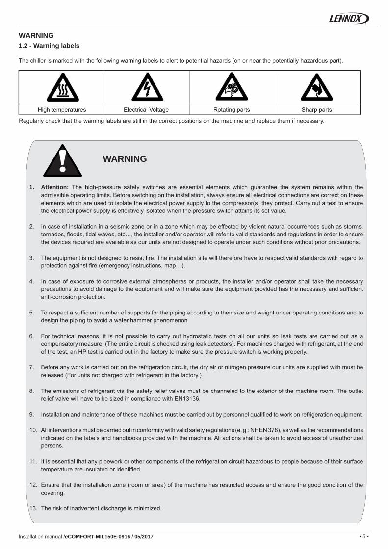
1. Attention: The high-pressure safety switches are essential elements which guarantee the system remains within the admissible operating limits. Before switching on the installation, always ensure all electrical connections are correct on these elements which are used to isolate the electrical power supply to the compressor(s) they protect. Carry out a test to ensure the electrical power supply is effectively isolated when the pressure switch attains its set value.
2. In case of installation in a seismic zone or in a zone which may be effected by violent natural occurrences such as storms, tornados, fl oods, tidal waves, etc…, the installer and/or operator will refer to valid standards and regulations in order to ensure the devices required are available as our units are not designed to operate under such conditions without prior precautions.
3. The equipment is not designed to resist fi re. The installation site will therefore have to respect valid standards with regard to protection against fi re (emergency instructions, map…).
4. In case of exposure to corrosive external atmospheres or products, the installer and/or operator shall take the necessary precautions to avoid damage to the equipment and will make sure the equipment provided has the necessary and suffi cient anti-corrosion protection.
5. To respect a suffi cient number of supports for the piping according to their size and weight under operating conditions and to design the piping to avoid a water hammer phenomenon
6. For technical reasons, it is not possible to carry out hydrostatic tests on all our units so leak tests are carried out as a compensatory measure. (The entire circuit is checked using leak detectors). For machines charged with refrigerant, at the end of the test, an HP test is carried out in the factory to make sure the pressure switch is working properly.
7. Before any work is carried out on the refrigeration circuit, the dry air or nitrogen pressure our units are supplied with must be released (For units not charged with refrigerant in the factory.)
8. The emissions of refrigerant via the safety relief valves must be channeled to the exterior of the machine room. The outlet relief valve will have to be sized in compliance with EN13136.
9. Installation and maintenance of these machines must be carried out by personnel qualifi ed to work on refrigeration equipment.
10. All interventions must be carried out in conformity with valid safety regulations (e. g.: NF EN 378), as well as the recommendations indicated on the labels and handbooks provided with the machine. All actions shall be taken to avoid access of unauthorized persons.
11. It is essential that any pipework or other components of the refrigeration circuit hazardous to people because of their surface temperature are insulated or identifi ed.
12. Ensure that the installation zone (room or area) of the machine has restricted access and ensure the good condition of the covering.
13. The risk of inadvertent discharge is minimized.
WARNING
WARNING1.2 - Warning labels
The chiller is marked with the following warning labels to alert to potential hazards (on or near the potentially hazardous part).
Regularly check that the warning labels are still in the correct positions on the machine and replace them if necessary.
High temperatures Electrical Voltage Rotating parts Sharp parts
• 6 •
°C
°C
°C
A
A
A
A
A
A
A
A
Installation manual /eCOMFORT-MIL150E-0916 / 05/2017
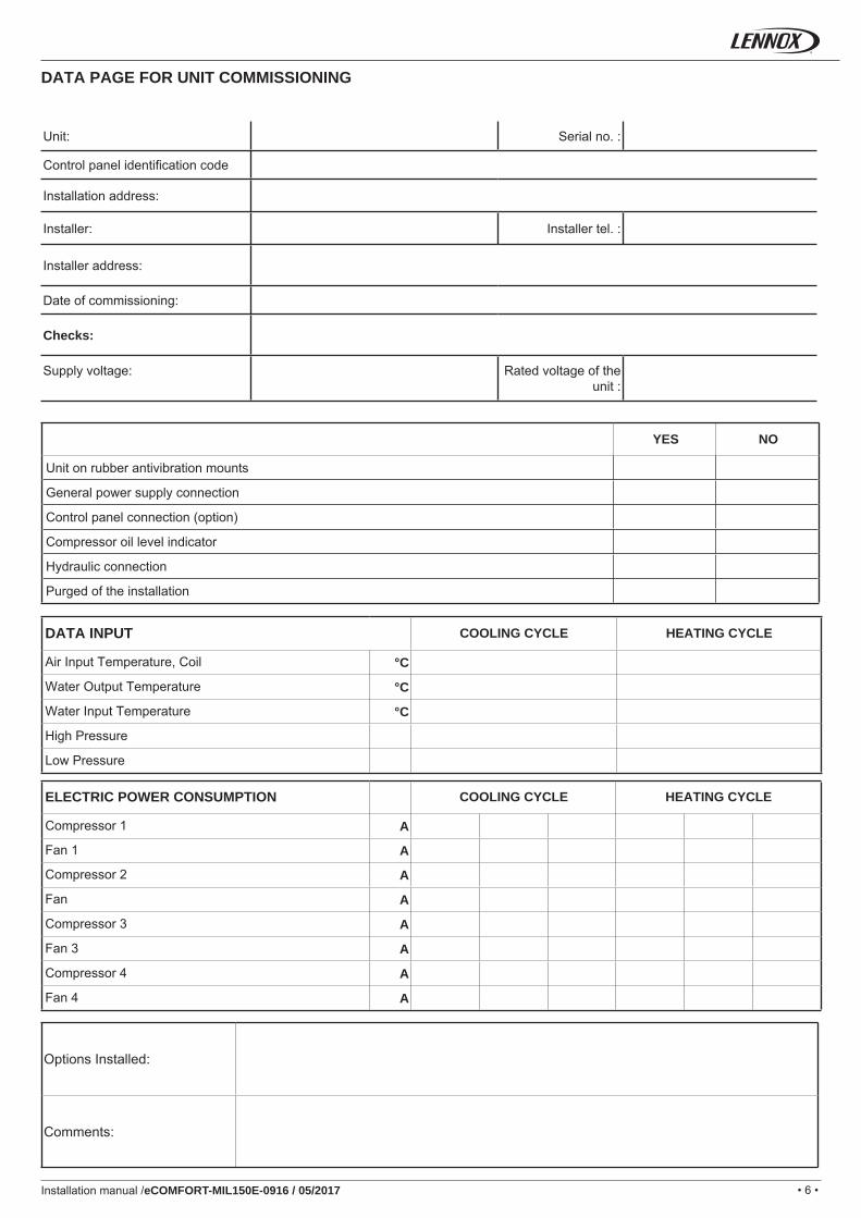
DATA PAGE FOR UNIT COMMISSIONING
Unit: Serial no. :
Control panel identifi cation code
Installation address:
Installer: Installer tel. :
Installer address:
Date of commissioning:
Checks:
Supply voltage: Rated voltage of the unit :
Options Installed:
Comments:
DATA INPUT COOLING CYCLE HEATING CYCLE
Air Input Temperature, Coil
Water Output Temperature
Water Input Temperature
High Pressure
Low Pressure
ELECTRIC POWER CONSUMPTION COOLING CYCLE HEATING CYCLE
Compressor 1
Fan 1
Compressor 2
Fan
Compressor 3
Fan 3
Compressor 4
Fan 4
YES NO
Unit on rubber antivibration mounts
General power supply connection
Control panel connection (option)
Compressor oil level indicator
Hydraulic connection
Purged of the installation
• 7 •
GA C 020 S M 1 M
LNCJSEASHIFPACTRCPGRLLWTPHRFRLKDSPLPDPLPSPELDPELSPHPDPHPSPEHDPEHBYVCWTNGWTHSWTHHEWFSWFIFKGRLAPEPAPPPAPPWECLOBNETMBUSMBIPDM60DS60DCBOELMEPHCTPOWFSOFT
EBFM1EBFM2ALWAAVUBSLCR
Installation manual /eCOMFORT-MIL150E-0916 / 05/2017
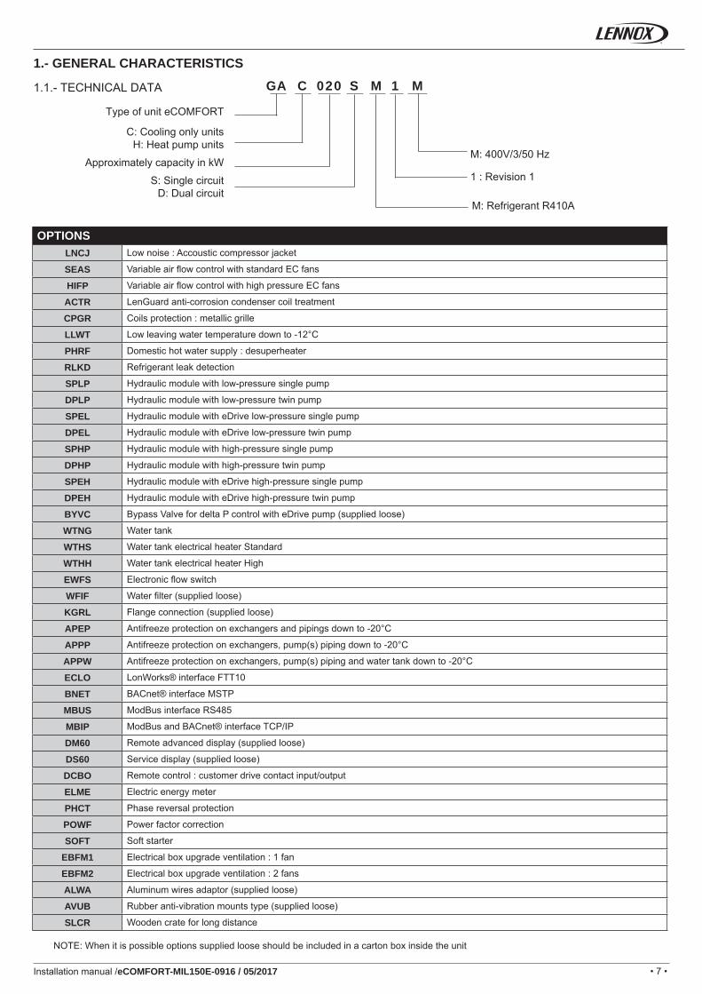
1.- GENERAL CHARACTERISTICS
C: Cooling only unitsH: Heat pump units
Approximately capacity in kW
S: Single circuitD: Dual circuit
M: Refrigerant R410A
M: 400V/3/50 Hz
1.1.- TECHNICAL DATA
Type of unit eCOMFORT
1 : Revision 1
OPTIONSLow noise : Accoustic compressor jacket
Variable air fl ow control with standard EC fans
Variable air fl ow control with high pressure EC fans
LenGuard anti-corrosion condenser coil treatment
Coils protection : metallic grille
Low leaving water temperature down to -12°C
Domestic hot water supply : desuperheater
Refrigerant leak detection
Hydraulic module with low-pressure single pump
Hydraulic module with low-pressure twin pump
Hydraulic module with eDrive low-pressure single pump
Hydraulic module with eDrive low-pressure twin pump
Hydraulic module with high-pressure single pump
Hydraulic module with high-pressure twin pump
Hydraulic module with eDrive high-pressure single pump
Hydraulic module with eDrive high-pressure twin pump
Bypass Valve for delta P control with eDrive pump (supplied loose)
Water tank
Water tank electrical heater Standard
Water tank electrical heater High
Electronic fl ow switch
Water fi lter (supplied loose)
Flange connection (supplied loose)
Antifreeze protection on exchangers and pipings down to -20°C
Antifreeze protection on exchangers, pump(s) piping down to -20°C
Antifreeze protection on exchangers, pump(s) piping and water tank down to -20°C
LonWorks® interface FTT10
BACnet® interface MSTP
ModBus interface RS485
ModBus and BACnet® interface TCP/IP
Remote advanced display (supplied loose)
Service display (supplied loose)
Remote control : customer drive contact input/output
Electric energy meter
Phase reversal protection
Power factor correction
Soft starter
Electrical box upgrade ventilation : 1 fan
Electrical box upgrade ventilation : 2 fans
Aluminum wires adaptor (supplied loose)
Rubber anti-vibration mounts type (supplied loose)
Wooden crate for long distance
NOTE: When it is possible options supplied loose should be included in a carton box inside the unit
• 8 •
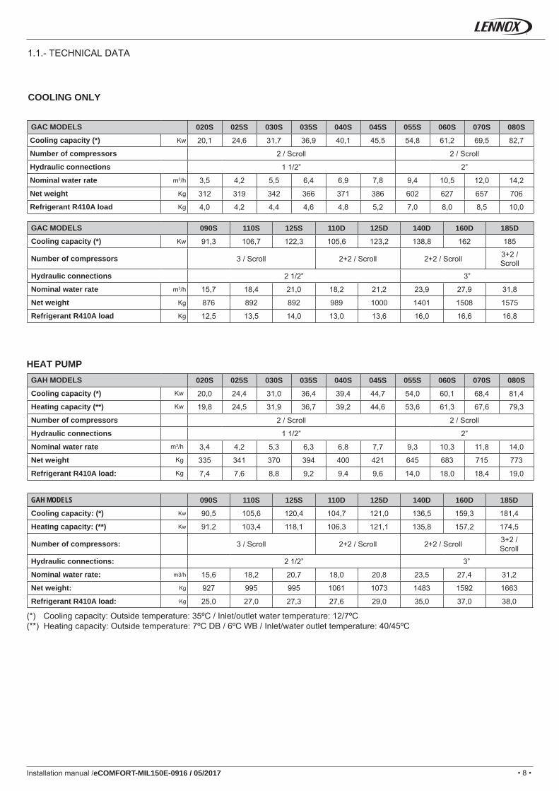
020S 025S 030S 035S 040S 045S 055S 060S 070S 080SKw 20,1 24,6 31,7 36,9 40,1 45,5 54,8 61,2 69,5 82,7
2 / Scroll 2 / Scroll
1 1/2” 2”
m3/h 3,5 4,2 5,5 6,4 6,9 7,8 9,4 10,5 12,0 14,2
Kg 312 319 342 366 371 386 602 627 657 706
Kg 4,0 4,2 4,4 4,6 4,8 5,2 7,0 8,0 8,5 10,0
090S 110S 125S 110D 125D 140D 160D 185DKw 91,3 106,7 122,3 105,6 123,2 138,8 162 185
3 / Scroll 2+2 / Scroll 2+2 / Scroll 3+2 / Scroll
2 1/2” 3”
m3/h 15,7 18,4 21,0 18,2 21,2 23,9 27,9 31,8
Kg 876 892 892 989 1000 1401 1508 1575
Kg 12,5 13,5 14,0 13,0 13,6 16,0 16,6 16,8
020S 025S 030S 035S 040S 045S 055S 060S 070S 080SKw 20,0 24,4 31,0 36,4 39,4 44,7 54,0 60,1 68,4 81,4
Kw 19,8 24,5 31,9 36,7 39,2 44,6 53,6 61,3 67,6 79,3
2 / Scroll 2 / Scroll
1 1/2” 2”
m3/h 3,4 4,2 5,3 6,3 6,8 7,7 9,3 10,3 11,8 14,0
Kg 335 341 370 394 400 421 645 683 715 773
Kg 7,4 7,6 8,8 9,2 9,4 9,6 14,0 18,0 18,4 19,0
090S 110S 125S 110D 125D 140D 160D 185DKw 90,5 105,6 120,4 104,7 121,0 136,5 159,3 181,4
Kw 91,2 103,4 118,1 106,3 121,1 135,8 157,2 174,5
3 / Scroll 2+2 / Scroll 2+2 / Scroll 3+2 / Scroll
2 1/2” 3”
m3/h 15,6 18,2 20,7 18,0 20,8 23,5 27,4 31,2
Kg 927 995 995 1061 1073 1483 1592 1663
Kg 25,0 27,0 27,3 27,6 29,0 35,0 37,0 38,0
Installation manual /eCOMFORT-MIL150E-0916 / 05/2017
COOLING ONLY
HEAT PUMP
(*) Cooling capacity: Outside temperature: 35ºC / Inlet/outlet water temperature: 12/7ºC(**) Heating capacity: Outside temperature: 7ºC DB / 6ºC WB / Inlet/water outlet temperature: 40/45ºC
GAC MODELS
Cooling capacity (*)
Number of compressors
Hydraulic connections
Nominal water rate
Net weight
Refrigerant R410A load
GAC MODELS
Cooling capacity (*)
Number of compressors
Hydraulic connections
Nominal water rate
Net weight
Refrigerant R410A load
GAH MODELS
Cooling capacity (*)
Heating capacity (**)
Number of compressors
Hydraulic connections
Nominal water rate
Net weight
Refrigerant R410A load:
GAH MODELS
Cooling capacity: (*)
Heating capacity: (**)
Number of compressors:
Hydraulic connections:
Nominal water rate:
Net weight:
Refrigerant R410A load:
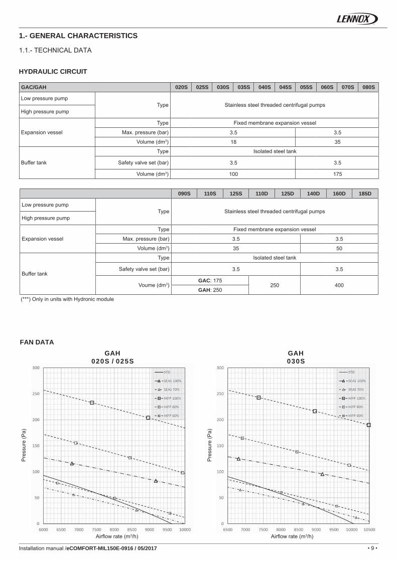
1.1.- TECHNICAL DATA
• 9 •
GAC/GAH 020S 025S 030S 035S 040S 045S 055S 060S 070S 080S
3.5 3.5
18 35
3.5 3.5
100 175
090S 110S 125S 110D 125D 140D 160D 185D
3.5 3.5
35 50
3.5 3.5
GAC: 175250 400
GAH: 250
GAH020S / 025S
GAH030S
Installation manual /eCOMFORT-MIL150E-0916 / 05/2017
1.1.- TECHNICAL DATA
1.- GENERAL CHARACTERISTICS
FAN DATA
HYDRAULIC CIRCUIT
(***) Only in units with Hydronic module
Low pressure pumpType Stainless steel threaded centrifugal pumps
High pressure pump
Expansion vessel
Type Fixed membrane expansion vessel
Max. pressure (bar)
Volume (dm3)
Buffer tank
Type Isolated steel tank
Safety valve set (bar)
Volume (dm3)
Low pressure pumpType Stainless steel threaded centrifugal pumps
High pressure pump
Expansion vessel
Type Fixed membrane expansion vessel
Max. pressure (bar)
Volume (dm3)
Buffer tank
Type Isolated steel tank
Safety valve set (bar)
Voume (dm3)
Airfl ow rate (m3/h) Airfl ow rate (m3/h)
Pre
ssur
e (P
a)
Pre
ssur
e (P
a)
• 10 •
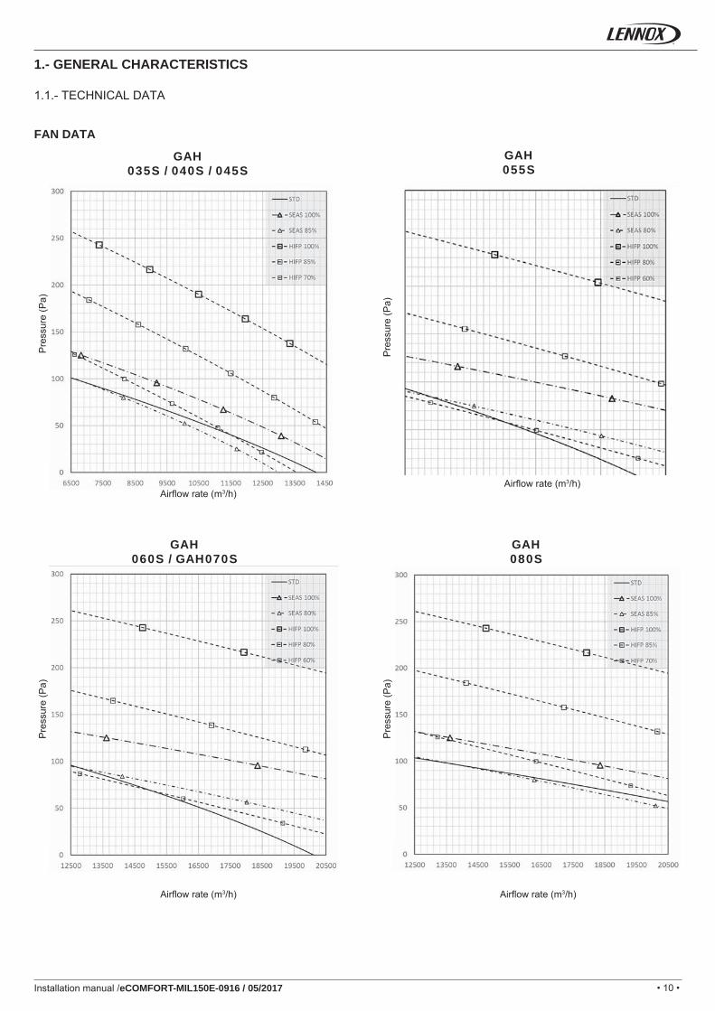
GAH035S / 040S / 045S
GAH055S
GAH060S / GAH070S
GAH080S
Installation manual /eCOMFORT-MIL150E-0916 / 05/2017
1.1.- TECHNICAL DATA
1.- GENERAL CHARACTERISTICS
FAN DATA
Airfl ow rate (m3/h)
Pre
ssur
e (P
a)
Airfl ow rate (m3/h)
Pre
ssur
e (P
a)
Airfl ow rate (m3/h)
Pre
ssur
e (P
a)
Airfl ow rate (m3/h)
Pre
ssur
e (P
a)
• 11 •
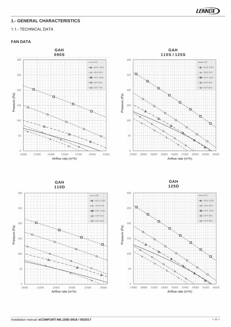
GAH090S
GAH110S / 125S
GAH110D
GAH125D
Installation manual /eCOMFORT-MIL150E-0916 / 05/2017
1.1.- TECHNICAL DATA
1.- GENERAL CHARACTERISTICS
FAN DATA
Airfl ow rate (m3/h)
Pre
ssur
e (P
a)
Airfl ow rate (m3/h)
Pre
ssur
e (P
a)
Airfl ow rate (m3/h)
Pre
ssur
e (P
a)
Airfl ow rate (m3/h)
Pre
ssur
e (P
a)
• 12 •
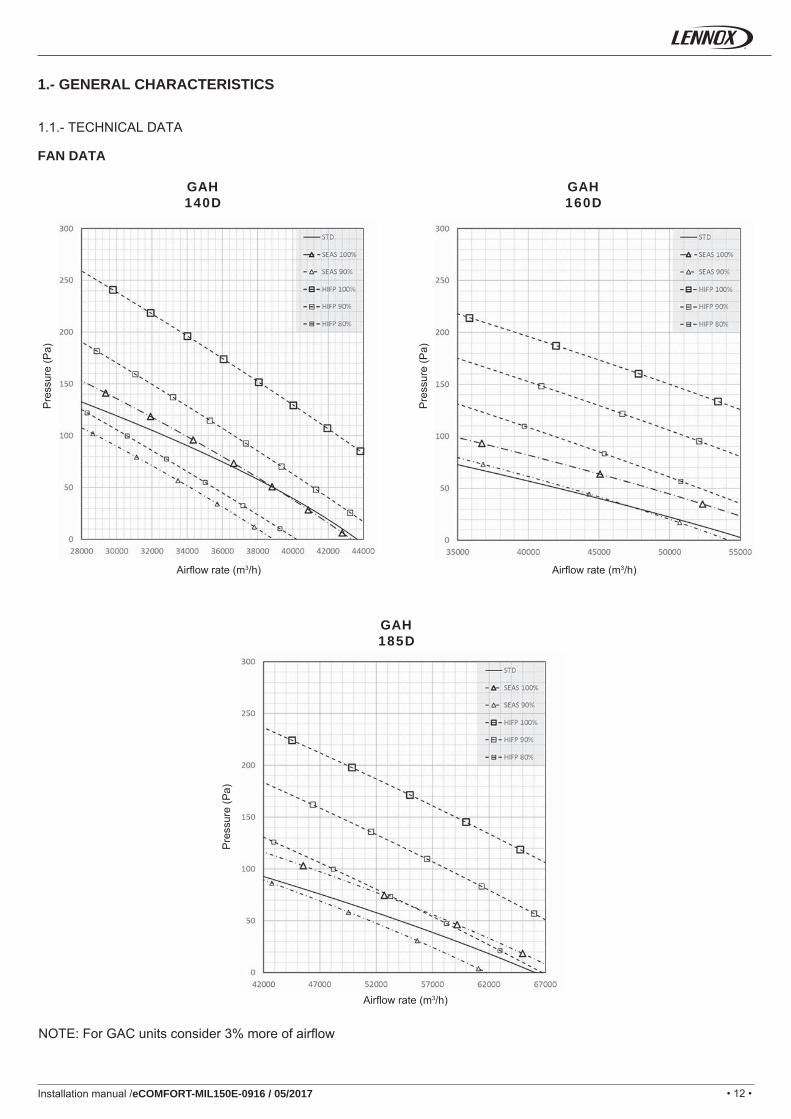
GAH140D
GAH160D
GAH185D
Installation manual /eCOMFORT-MIL150E-0916 / 05/2017
1.1.- TECHNICAL DATA
1.- GENERAL CHARACTERISTICS
FAN DATA
NOTE: For GAC units consider 3% more of airfl ow
Airfl ow rate (m3/h)
Pre
ssur
e (P
a)
Airfl ow rate (m3/h)
Pre
ssur
e (P
a)
Airfl ow rate (m3/h)
Pre
ssur
e (P
a)
• 13 •
GAC/GAH 020S 025S 030S 035S 040S 045S 055S 060S 070S 080SkW 9,4 11,8 15,1 17,4 18,0 20,7 24,6 27,5 30,4 35,6
A 17,2 21,8 31,2 32,2 34,6 38,6 46,4 55,4 64,4 72,4
A 52,2 63 91,2 118,2 119,4 148,4 142,4 164,4 173,4 212,4A 35 42,4 61,2 77,8 79,0 97,2 95,2 108,4 117,4 142,8
kW 0,2 0,2 0,2 -0,1 -0,1 -0,1 0,5 0,5 0,5 -0,1A 0,2 0,2 0,2 -0,8 -0,8 -0,8 0,4 0,4 0,4 -1,6
kW 1,1 1,1 1,1 0,8 0,8 0,8 2,2 2,2 2,2 1,6A 1,5 1,5 1,5 0,5 0,5 0,5 3 3 3 0,1
kW 0,6 0,6 0,8 0,8 1,1 1,1 1,1 1,1 1,1 1,1A 1,5 1,5 1,7 1,7 2,5 2,5 2,5 2,5 2,5 2,5
kW 1,1 1,1 1,1 0,8 0,8 0,8 2,2 2,2 2,2 1,6A 2,5 2,5 3,3 3,3 3,3 3,3 3,3 3,3 3,3 3,3
kW 2,3 2,3 2,3 2,3 2,3 2,3 6 6 6 6A 3,3 3,3 3,3 3,3 3,3 3,3 8,7 8,7 8,7 8,7
kW 9 9 9 9 9 9 18 18 18 18A 13 13 13 13 13 13 26 26 26 26
kW 12 12 12 12 12 12 24 24 24 24A 17,3 17,3 17,3 17,3 17,3 17,3 34,7 34,7 34,7 34,7
GAC/GAH 090S 110S 125S 110D 125D 140D 160D 185DkW 40,8 47,7 54,6 48,6 56,5 62,3 71,2 83,3
A 79,4 100,8 109,8 92,4 113,8 131,8 144,9 173,2
A 172,4 209,8 249,8 188,4 222,8 240,8 284,9 313,2A 125,2 153,8 180,2 141,2 166,8 184,8 215,3 243,6
kW -0,1 -0,5 -0,5 -0,1 -0,5 -0,5 -0,2 -0,6A -1,6 -2,4 -2,4 -1,6 -2,4 -2,4 -3,3 -4,0
kW 1,6 2,1 2,1 1,6 2,1 2,1 3,2 3,7A 0,1 1,2 1,2 0,1 1,2 1,2 1,9 2,2
kW 1,5 1,5 1,5 1,5 1,5 3 3 3A 3,3 3,3 3,3 3,3 3,3 6,5 6,5 6,5
kW 1,6 2,1 2,1 1,6 2,1 2,1 3,2 3,7A 6,5 6,5 6,5 6,5 6,5 7,6 7,6 7,6
kW 9 9 9 9 9 12 12 12A 13 13 13 13 13 17,3 17,3 17,3
kW 27 27 27 27 27 36 36 36A 39 39 39 39 39 52 52 52
kW 36 36 36 36 36 48 48 48A 52 52 52 52 52 69,4 69,4 69,4
SEASHIFP
Installation manual /eCOMFORT-MIL150E-0916 / 05/2017
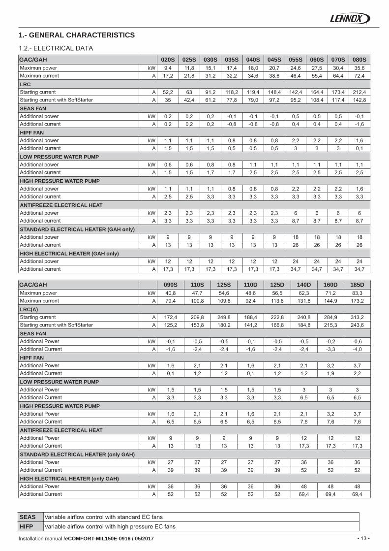
1.2.- ELECTRICAL DATA
1.- GENERAL CHARACTERISTICS
Maximun powerMaximun currentLRCStarting currentStarting current with SoftStarterSEAS FANAdditional powerAdditional currentHIPF FANAdditional power Additional currentLOW PRESSURE WATER PUMPAdditional power Additional currentHIGH PRESSURE WATER PUMPAdditional power Additional currentANTIFREEZE ELECTRICAL HEAT Additional power Additional currentSTANDARD ELECTRICAL HEATER (GAH only)Additional power Additional currentHIGH ELECTRICAL HEATER (GAH only)Additional power Additional current
Maximun powerMaximun currentLRC(A)Starting currentStarting current with SoftStarterSEAS FANAdditional PowerAdditional CurrentHIPF FANAdditional PowerAdditional CurrentLOW PRESSURE WATER PUMPAdditional PowerAdditional CurrentHIGH PRESSURE WATER PUMPAdditional PowerAdditional CurrentANTIFREEZE ELECTRICAL HEAT Additional PowerAdditional CurrentSTANDARD ELECTRICAL HEATER (only GAH)Additional PowerAdditional CurrentHIGH ELECTRICAL HEATER (only GAH)Additional PowerAdditional Current
Variable airfl ow control with standard EC fansVariable airfl ow control with high pressure EC fans
• 14 •
1 6 11
2 7 12
3 8 13
4 914
5 10
8, 9, 10, 11, 12, 13 4, 5, 6, 7, 8, 9, 10, 11, 12, 13, 14 2, 3, 4, 5, 6, 7, 8, 9, 10, 11,12, 13, 14
89
10
11
12 12
12
13
13
1
4
5
6
789
10
11
12 12
12
141413
13
1´
12
34
567
89
10
11
12
12
12
11
13
13
14
14
Installation manual /eCOMFORT-MIL150E-0916 / 05/2017
STANDARD UNIT
Customer connection
Hydraulic connections
Inside terminal unit
To be connected by the installer
Carried out by the installer
UNIT WITH WATER PUMP OPTION
Customer connection
Hydraulic connections
Inside terminal unit
To be connected by the installer
Carried out by the installer
UNIT WITH WATER TANK OPTIONInside terminal unit
To be connected by the installer
Carried out by the installer
Hydraulic connections
Customer connection
COMPONENTS:
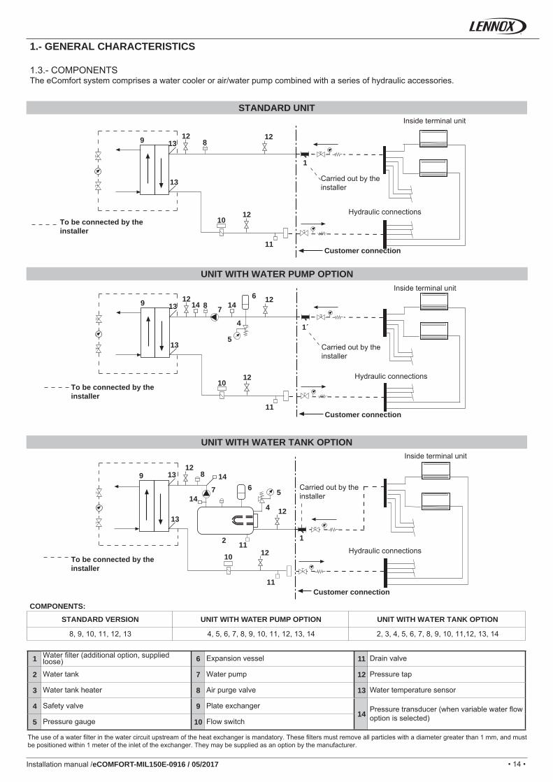
STANDARD VERSION UNIT WITH WATER PUMP OPTION UNIT WITH WATER TANK OPTION
Water fi lter (additional option, supplied loose) Expansion vessel Drain valve
Water tank Water pump Pressure tap
Water tank heater Air purge valve Water temperature sensor
Safety valve Plate exchanger Pressure transducer (when variable water fl ow option is selected)Pressure gauge Flow switch
1.- GENERAL CHARACTERISTICS
1.3.- COMPONENTSThe eComfort system comprises a water cooler or air/water pump combined with a series of hydraulic accessories.
The use of a water fi lter in the water circuit upstream of the heat exchanger is mandatory. These fi lters must remove all particles with a diameter greater than 1 mm, and must be positioned within 1 meter of the inlet of the exchanger. They may be supplied as an option by the manufacturer.
• 15 •
°C9
8
7
6
5
4
3
2
1-10 -8 -6 -4 -2 0 2 4 6 8 10
Installation manual /eCOMFORT-MIL150E-0916 / 05/2017
1.- GENERAL CHARACTERISTICS
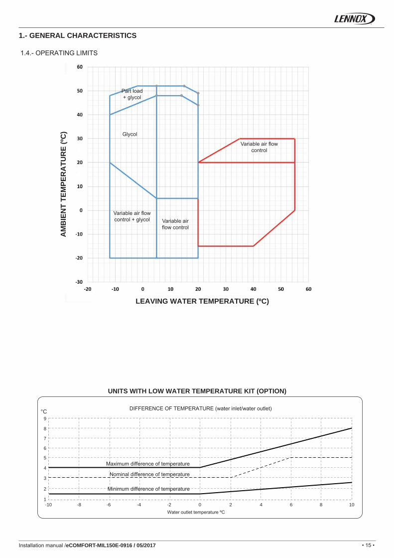
1.4.- OPERATING LIMITS
Glycol
Variable air fl ow control
Variable air fl ow control + glycol
Part load + glycol
Variable air fl ow control
AM
BIE
NT
TEM
PER
ATU
RE
(ºC
)
LEAVING WATER TEMPERATURE (ºC)
UNITS WITH LOW WATER TEMPERATURE KIT (OPTION)
DIFFERENCE OF TEMPERATURE (water inlet/water outlet)
Maximum difference of temperature
Nominal difference of temperature
Minimum difference of temperature
Water outlet temperature ºC
• 16 •
GAC/GAH020S - 025S
GAC/GAH030S - 035S
GAC/GAH040S - 045S
GAC/GAH055S - 060S
Installation manual /eCOMFORT-MIL150E-0916 / 05/2017
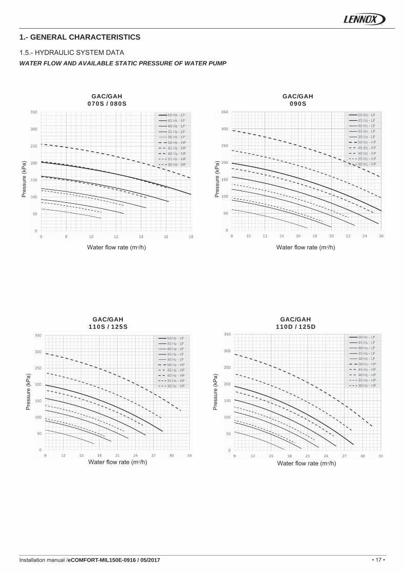
1.- GENERAL CHARACTERISTICS
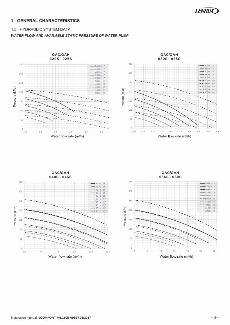
1.5.- HYDRAULIC SYSTEM DATAWATER FLOW AND AVAILABLE STATIC PRESSURE OF WATER PUMP
Pre
ssur
e (k
Pa)
Pre
ssur
e (k
Pa)
Pre
ssur
e (k
Pa)
Pre
ssur
e (k
Pa)
Water fl ow rate (m3/h) Water fl ow rate (m3/h)
Water fl ow rate (m3/h) Water fl ow rate (m3/h)
• 17 •
GAC/GAH070S / 080S
GAC/GAH090S
GAC/GAH110S / 125S
GAC/GAH110D / 125D
Installation manual /eCOMFORT-MIL150E-0916 / 05/2017
1.- GENERAL CHARACTERISTICS
1.5.- HYDRAULIC SYSTEM DATAWATER FLOW AND AVAILABLE STATIC PRESSURE OF WATER PUMP
Pre
ssur
e (K
Pa)
Pre
ssur
e (k
Pa)
Pre
ssur
e (k
Pa)
Pre
ssur
e (k
Pa)
Pre
ssur
e (k
Pa)
Water fl ow rate (m3/h)Water fl ow rate (m3/h)
Water fl ow rate (m3/h) Water fl ow rate (m3/h)
• 18 •
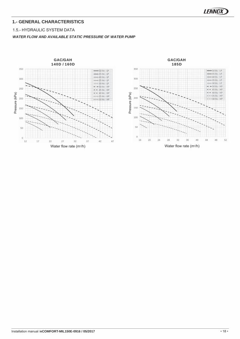
GAC/GAH140D / 160D
GAC/GAH185D
Installation manual /eCOMFORT-MIL150E-0916 / 05/2017
1.- GENERAL CHARACTERISTICS
1.5.- HYDRAULIC SYSTEM DATA
WATER FLOW AND AVAILABLE STATIC PRESSURE OF WATER PUMP
Water fl ow rate (m3/h) Water fl ow rate (m3/h)
Pre
ssur
e (k
Pa)
Pre
ssur
e (k
Pa)
• 19 •
GAC
/H 0
20S
0
45S
GAC/H 05
5S
080S
GAC/H 09
0S
125D
GAC/H 140D 185D
140
120
100
80
60
40
20
00 5 10 15 20 25 30 35 40 45 50 55
GAC/H 185D
GAC/H 140D
- 160
D
GAC/H 110S - 125S
GAC/H 11
0D - 1
25D
GAC/H 070S - 080S - 0
90S
GAC/
H 05
5S -
060S
GAC
/H 0
20S
- 025
SG
AC/H
030
S - 0
35S
GAC
/H 0
40S
- 045
S
-
00
20
40
60
80
100
120
140
160
180
5 10 15 20 25 30 35 40 45 50 55
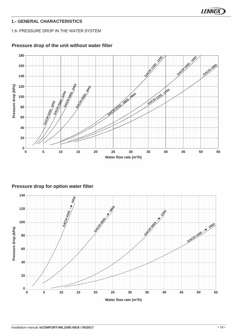
Installation manual /eCOMFORT-MIL150E-0916 / 05/2017
1.- GENERAL CHARACTERISTICS
1.6- PRESSURE DROP IN THE WATER SYSTEM
Water fl ow rate (m3/h)
Water fl ow rate (m3/h)
Pres
sure
dro
p (k
Pa)
Pres
sure
dro
p (k
Pa)
Pressure drop of the unit without water filter
Pressure drop for option water filter
• 20 •
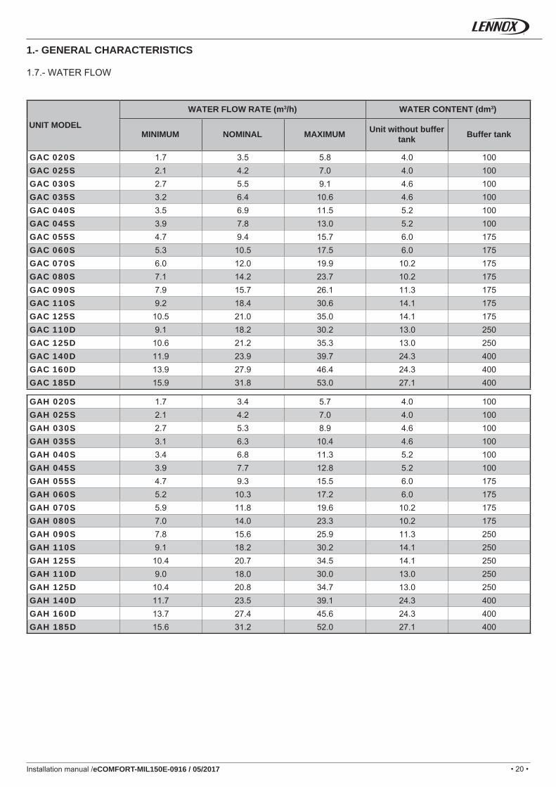
GAC 020S 1.7 3.5 5.8 4.0 100GAC 025S 2.1 4.2 7.0 4.0 100GAC 030S 2.7 5.5 9.1 4.6 100GAC 035S 3.2 6.4 10.6 4.6 100GAC 040S 3.5 6.9 11.5 5.2 100GAC 045S 3.9 7.8 13.0 5.2 100GAC 055S 4.7 9.4 15.7 6.0 175GAC 060S 5.3 10.5 17.5 6.0 175GAC 070S 6.0 12.0 19.9 10.2 175GAC 080S 7.1 14.2 23.7 10.2 175GAC 090S 7.9 15.7 26.1 11.3 175GAC 110S 9.2 18.4 30.6 14.1 175GAC 125S 10.5 21.0 35.0 14.1 175GAC 110D 9.1 18.2 30.2 13.0 250GAC 125D 10.6 21.2 35.3 13.0 250GAC 140D 11.9 23.9 39.7 24.3 400GAC 160D 13.9 27.9 46.4 24.3 400GAC 185D 15.9 31.8 53.0 27.1 400
GAH 020S 1.7 3.4 5.7 4.0 100GAH 025S 2.1 4.2 7.0 4.0 100GAH 030S 2.7 5.3 8.9 4.6 100GAH 035S 3.1 6.3 10.4 4.6 100GAH 040S 3.4 6.8 11.3 5.2 100GAH 045S 3.9 7.7 12.8 5.2 100GAH 055S 4.7 9.3 15.5 6.0 175GAH 060S 5.2 10.3 17.2 6.0 175GAH 070S 5.9 11.8 19.6 10.2 175GAH 080S 7.0 14.0 23.3 10.2 175GAH 090S 7.8 15.6 25.9 11.3 250GAH 110S 9.1 18.2 30.2 14.1 250GAH 125S 10.4 20.7 34.5 14.1 250GAH 110D 9.0 18.0 30.0 13.0 250GAH 125D 10.4 20.8 34.7 13.0 250GAH 140D 11.7 23.5 39.1 24.3 400GAH 160D 13.7 27.4 45.6 24.3 400GAH 185D 15.6 31.2 52.0 27.1 400
Installation manual /eCOMFORT-MIL150E-0916 / 05/2017
1.7.- WATER FLOW
1.- GENERAL CHARACTERISTICS
UNIT MODEL
WATER FLOW RATE (m3/h) WATER CONTENT (dm3)
MINIMUM NOMINAL MAXIMUM Unit without buffer tank Buffer tank
• 21 •
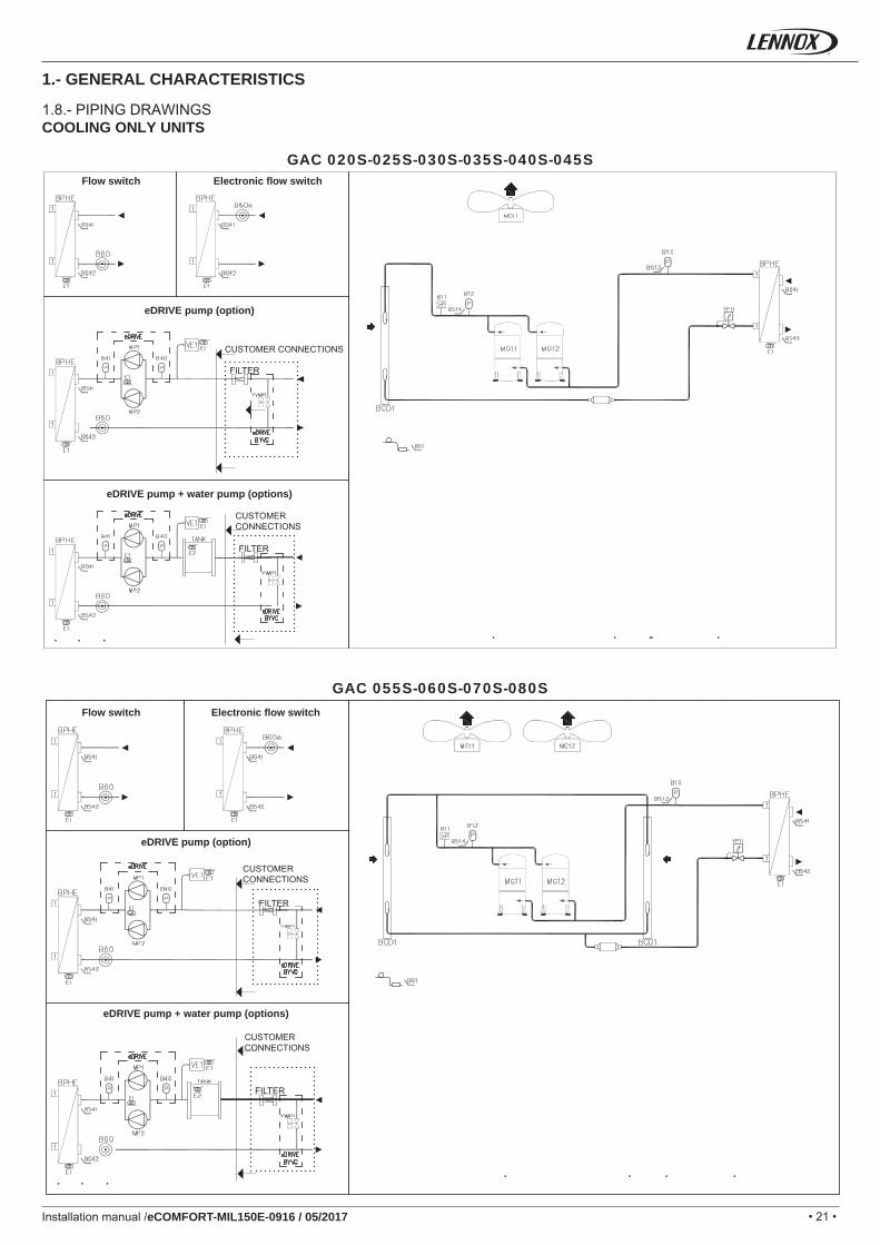
GAC 020S-025S-030S-035S-040S-045S
GAC 055S-060S-070S-080S
Installation manual /eCOMFORT-MIL150E-0916 / 05/2017
1.8.- PIPING DRAWINGSCOOLING ONLY UNITS
1.- GENERAL CHARACTERISTICS
CUSTOMER CONNECTIONS
FILTER
FILTER
Electronic fl ow switch
Electronic fl ow switch
eDRIVE pump (option)
eDRIVE pump + water pump (options)
eDRIVE pump (option)
Flow switch
Flow switch
CUSTOMER CONNECTIONS
CUSTOMER CONNECTIONS
CUSTOMER CONNECTIONS
FILTER
FILTER
eDRIVE pump + water pump (options)
• 22 • • 22 •
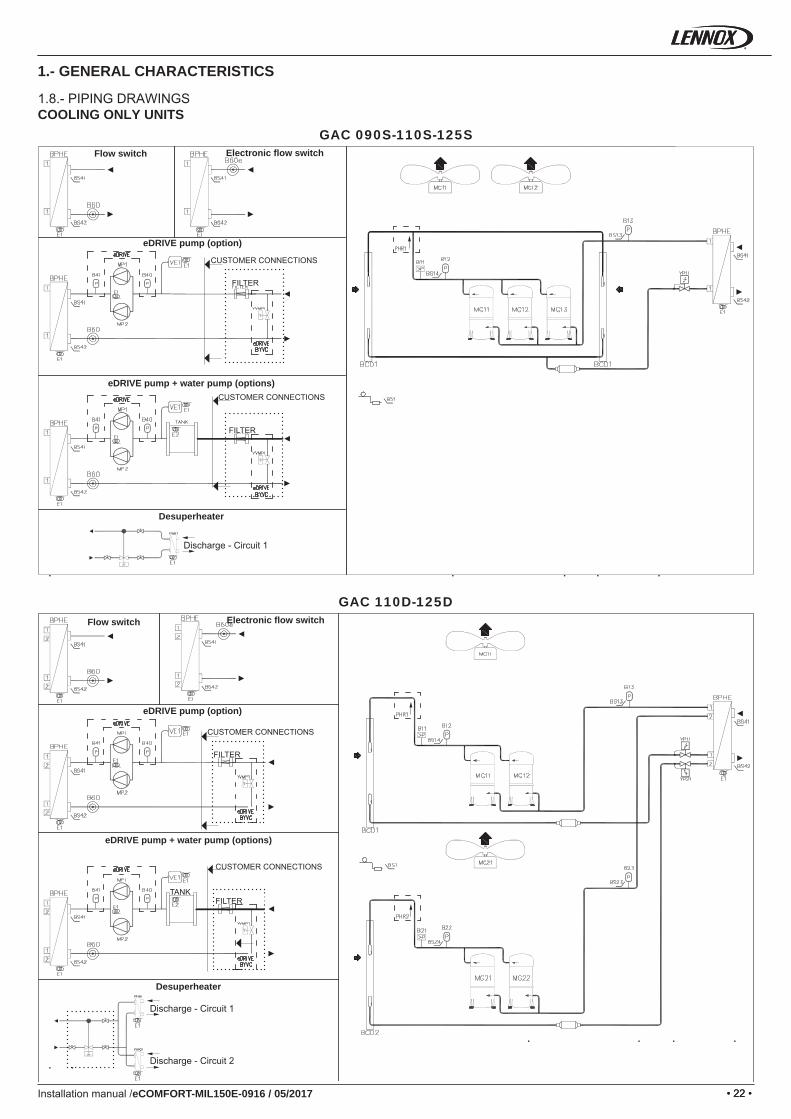
GAC 090S-110S-125S
GAC 110D-125D
Installation manual /eCOMFORT-MIL150E-0916 / 05/2017
1.- GENERAL CHARACTERISTICS
1.8.- PIPING DRAWINGSCOOLING ONLY UNITS
Electronic fl ow switch
Electronic fl ow switch
eDRIVE pump (option)
eDRIVE pump (option)
Flow switch
Flow switch
CUSTOMER CONNECTIONS
CUSTOMER CONNECTIONS
FILTER
FILTER
FILTER
FILTERTANK
eDRIVE pump + water pump (options)
eDRIVE pump + water pump (options)
Desuperheater
Desuperheater
Discharge - Circuit 1
Discharge - Circuit 1
Discharge - Circuit 2
CUSTOMER CONNECTIONS
CUSTOMER CONNECTIONS
• 23 •
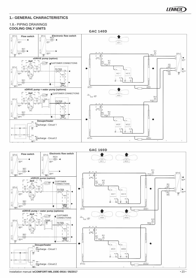
GAC 140D
GAC 160D
Installation manual /eCOMFORT-MIL150E-0916 / 05/2017
1.- GENERAL CHARACTERISTICS
1.8.- PIPING DRAWINGSCOOLING ONLY UNITS
Electronic fl ow switch
Electronic fl ow switch
eDRIVE pump (option)
Flow switch
Flow switch
eDRIVE pump + water pump (options)
Desuperheater
Desuperheater
CUSTOMER CONNECTIONS
CUSTOMER CONNECTIONS
FILTER
FILTER
Discharge - Circuit 1
Discharge - Circuit 1
Discharge - Circuit 2
Discharge - Circuit 2
CUSTOMER CONNECTIONS
eDRIVE pump (option)CUSTOMER CONNECTIONS
FILTER
FILTERTANK
eDRIVE pump + water pump (options)
• 24 • • 24 •
B11 BS41
B12 BS42
B13 E1
B21 E2
B22 E3-4-5-6
B23 LR
B40 MC
B41 MG
B60 MP
B60e PHR 1-2
BCD SLHE
BPHE VE1
BS1 YP11
BS13 YP21
BS14 YV12-22
BS23 YVMP1
BS24
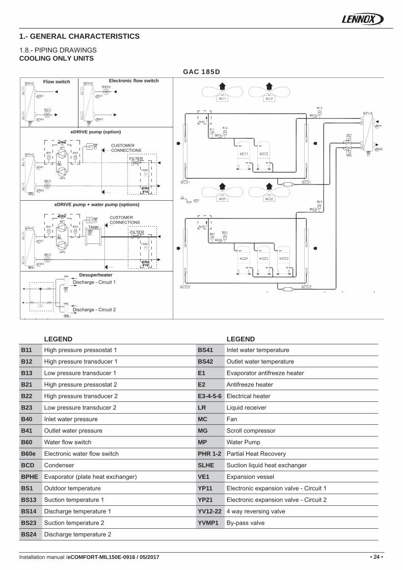
GAC 185D
Installation manual /eCOMFORT-MIL150E-0916 / 05/2017
1.- GENERAL CHARACTERISTICS
LEGEND LEGENDHigh pressure pressostat 1 Inlet water temperature
High pressure transducer 1 Outlet water temperature
Low pressure transducer 1 Evaporator antifreeze heater
High pressure pressostat 2 Antifreeze heater
High pressure transducer 2 Electrical heater
Low pressure transducer 2 Liquid receiver
Inlet water pressure Fan
Outlet water pressure Scroll compressor
Water fl ow switch Water Pump
Electronic water fl ow switch Partial Heat Recovery
Condenser Suction liquid heat exchanger
Evaporator (plate heat exchanger) Expansion vessel
Outdoor temperature Electronic expansion valve - Circuit 1
Suction temperature 1 Electronic expansion valve - Circuit 2
Discharge temperature 1 4 way reversing valve
Suction temperature 2 By-pass valve
Discharge temperature 2
1.8.- PIPING DRAWINGSCOOLING ONLY UNITS
Electronic fl ow switchFlow switch
DesuperheaterDischarge - Circuit 1
Discharge - Circuit 2
CUSTOMER CONNECTIONS
CUSTOMER CONNECTIONS
eDRIVE pump (option)
FILTERTANK
eDRIVE pump + water pump (options)
FILTER
• 25 •
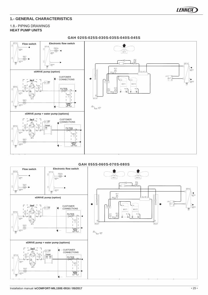
GAH 020S-025S-030S-035S-040S-045S
GAH 055S-060S-070S-080S
Installation manual /eCOMFORT-MIL150E-0916 / 05/2017
1.- GENERAL CHARACTERISTICS
1.8.- PIPING DRAWINGSHEAT PUMP UNITS
Electronic fl ow switch
Electronic fl ow switch
Flow switch
Flow switch
CUSTOMER CONNECTIONS
CUSTOMER CONNECTIONS
FILTER
FILTER
FILTER
FILTERTANK
TANK
eDRIVE pump (option)
eDRIVE pump (option)
eDRIVE pump + water pump (options)
eDRIVE pump + water pump (options)
CUSTOMER CONNECTIONS
CUSTOMER CONNECTIONS
• 26 • • 26 •
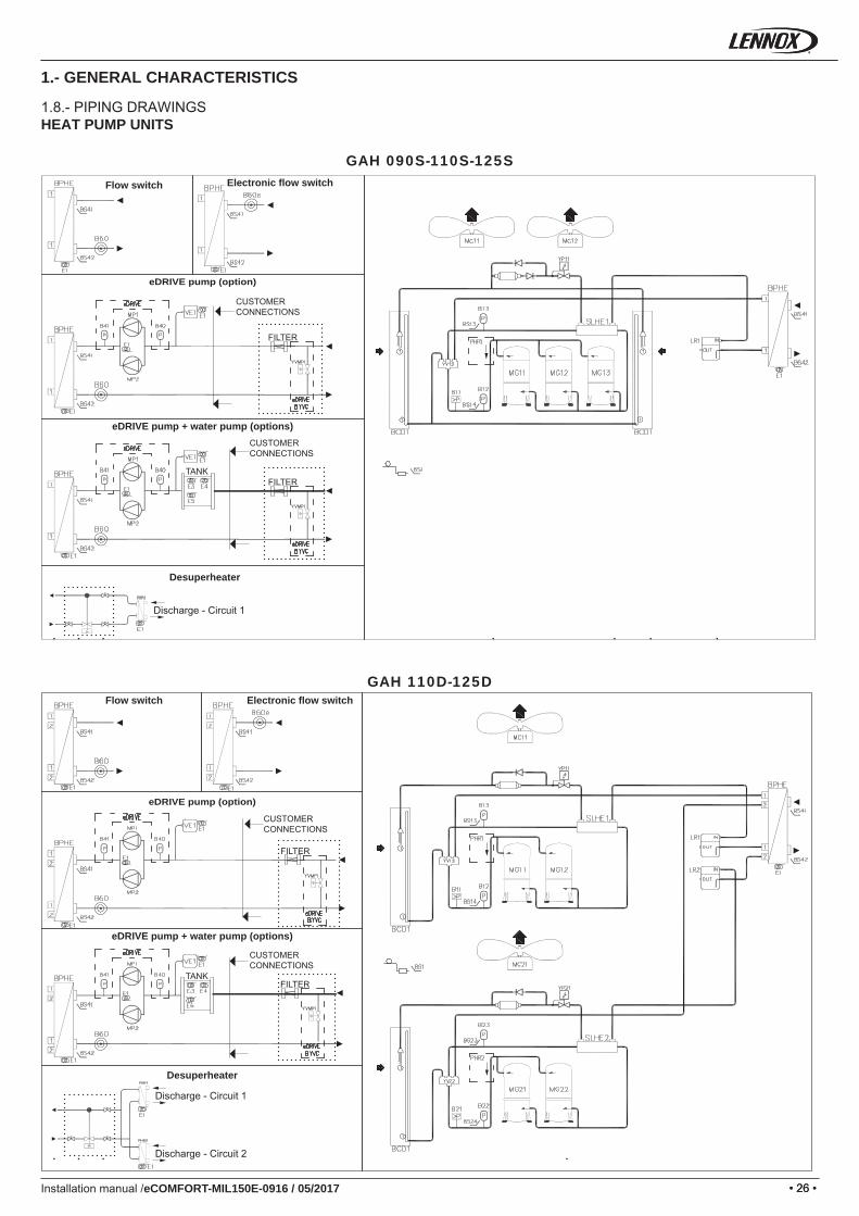
GAH 090S-110S-125S
GAH 110D-125D
Installation manual /eCOMFORT-MIL150E-0916 / 05/2017
1.- GENERAL CHARACTERISTICS
1.8.- PIPING DRAWINGSHEAT PUMP UNITS
Electronic fl ow switch
Electronic fl ow switch
Flow switch
Flow switch
FILTER
FILTER
FILTER
FILTER
TANK
TANK
eDRIVE pump (option)
eDRIVE pump + water pump (options)
CUSTOMER CONNECTIONS
CUSTOMER CONNECTIONS
CUSTOMER CONNECTIONS
CUSTOMER CONNECTIONS
Desuperheater
Discharge - Circuit 1
Desuperheater
Discharge - Circuit 1
Discharge - Circuit 2
eDRIVE pump + water pump (options)
eDRIVE pump (option)
• 27 •
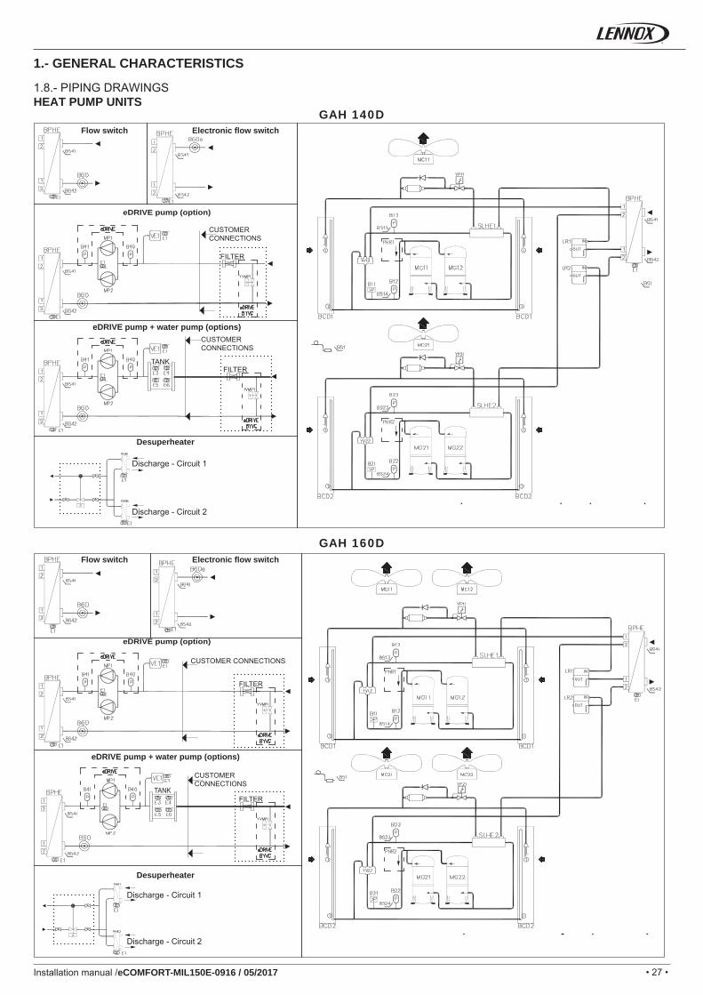
GAH 140D
GAH 160D
Installation manual /eCOMFORT-MIL150E-0916 / 05/2017
1.- GENERAL CHARACTERISTICS
1.8.- PIPING DRAWINGSHEAT PUMP UNITS
Desuperheater
Desuperheater
Discharge - Circuit 1
Discharge - Circuit 1
Discharge - Circuit 2
Discharge - Circuit 2
FILTER
FILTER
FILTER
FILTER
CUSTOMER CONNECTIONS
CUSTOMER CONNECTIONS
CUSTOMER CONNECTIONS
CUSTOMER CONNECTIONS
eDRIVE pump + water pump (options)
eDRIVE pump (option)
Electronic fl ow switchFlow switch
eDRIVE pump + water pump (options)
TANK
TANK
eDRIVE pump (option)
Electronic fl ow switchFlow switch
• 28 • • 28 •
B11 BS41
B12 BS42
B13 E1
B21 E2
B22 E3-4-5-6
B23 LR
B40 MC
B41 MG
B60 MP
B60e PHR 1-2
BCD SLHE
BPHE VE1
BS1 YP11
BS13 YP21
BS14 YV12-22
BS23 YVMP1
BS24
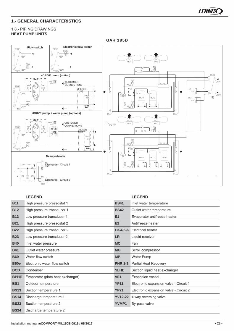
GAH 185D
Installation manual /eCOMFORT-MIL150E-0916 / 05/2017
1.- GENERAL CHARACTERISTICS
LEGEND LEGENDHigh pressure pressostat 1 Inlet water temperature
High pressure transducer 1 Outlet water temperature
Low pressure transducer 1 Evaporator antifreeze heater
High pressure pressostat 2 Antifreeze heater
High pressure transducer 2 Electrical heater
Low pressure transducer 2 Liquid receiver
Inlet water pressure Fan
Outlet water pressure Scroll compressor
Water fl ow switch Water Pump
Electronic water fl ow switch Partial Heat Recovery
Condenser Suction liquid heat exchanger
Evaporator (plate heat exchanger) Expansion vessel
Outdoor temperature Electronic expansion valve - Circuit 1
Suction temperature 1 Electronic expansion valve - Circuit 2
Discharge temperature 1 4 way reversing valve
Suction temperature 2 By-pass valve
Discharge temperature 2
1.8.- PIPING DRAWINGSHEAT PUMP UNITS
Electronic fl ow switchFlow switch
Desuperheater
Discharge - Circuit 1
Discharge - Circuit 2
CUSTOMER CONNECTIONS
CUSTOMER CONNECTIONS
eDRIVE pump (option)
FILTERTANK
eDRIVE pump + water pump (options)
FILTER
• 29 •
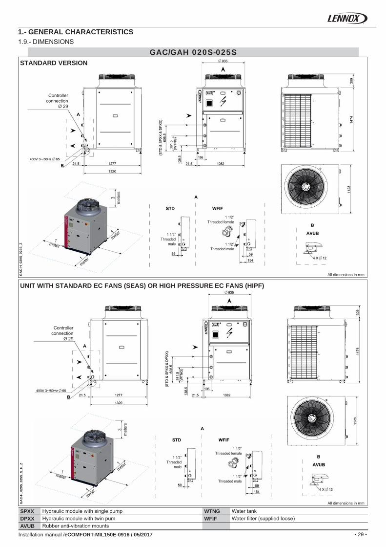
GAC/GAH 020S-025S
SPXX WTNGDPXX WFIFAVUB
GA
C-H
_020
S_02
5S_Z
GA
C-H
_020
S_02
5S_S
_H_Z
Installation manual /eCOMFORT-MIL150E-0916 / 05/2017
Controller connection
Ø 29
Controller connection
Ø 29
All dimensions in mm
All dimensions in mm
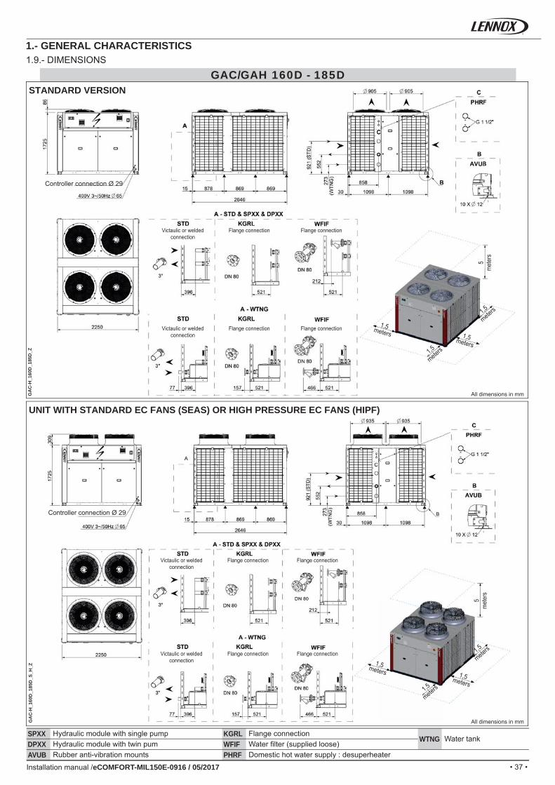
1.- GENERAL CHARACTERISTICS1.9.- DIMENSIONS
STANDARD VERSION
UNIT WITH STANDARD EC FANS (SEAS) OR HIGH PRESSURE EC FANS (HIPF)
3m
eter
s
1meter
1meter
1meter
3m
eter
s
1meter
1meter
1meter
Hydraulic module with single pump Water tankHydraulic module with twin pum Water fi lter (supplied loose)Rubber anti-vibration mounts
1 1/2” Threaded
male 1 1/2” Threaded male
1 1/2” Threaded female
1 1/2” Threaded
male
1 1/2” Threaded male
1 1/2” Threaded female
• 30 •
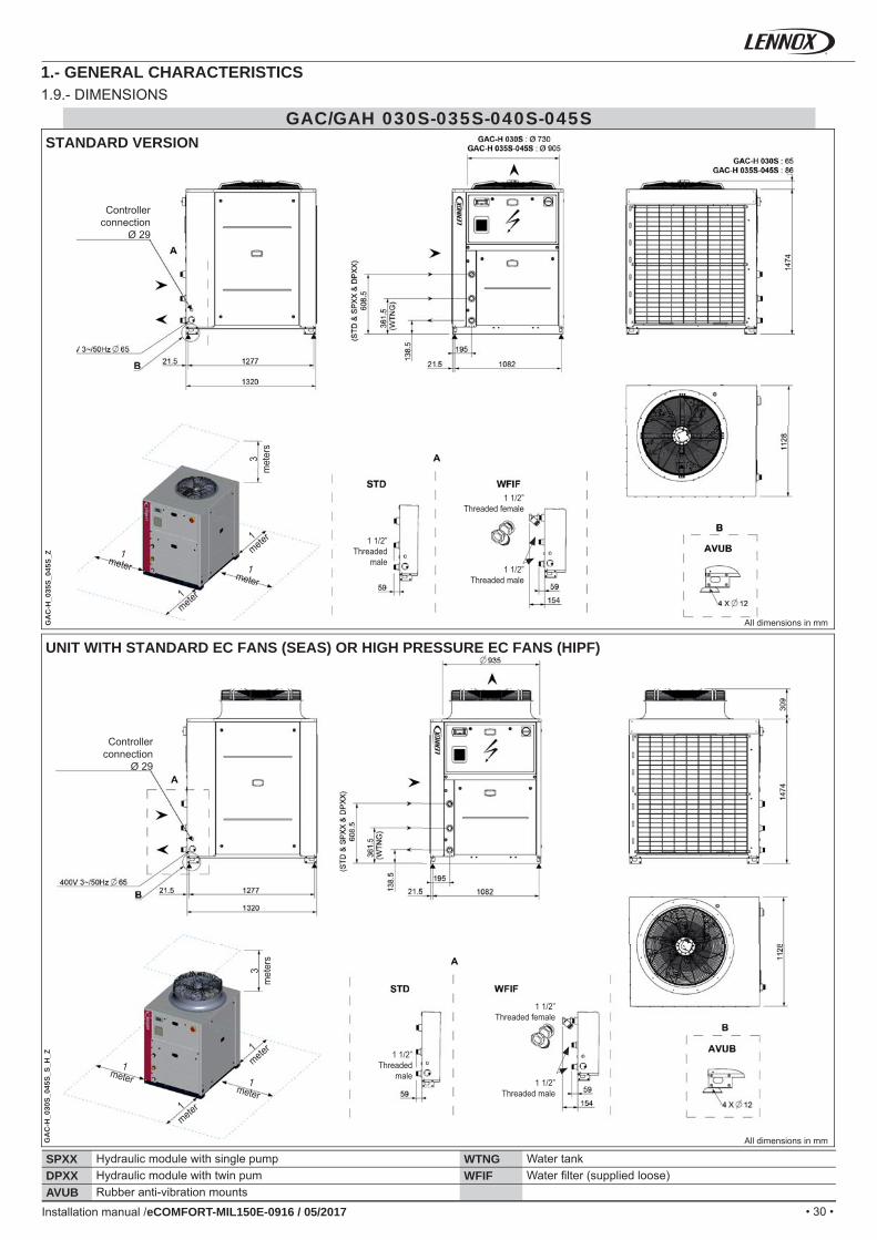
GAC/GAH 030S-035S-040S-045S
SPXX WTNGDPXX WFIFAVUB
GA
C-H
_035
S_04
5S_Z
GA
C-H
_030
S_04
5S_S
_H_Z
Installation manual /eCOMFORT-MIL150E-0916 / 05/2017
1.- GENERAL CHARACTERISTICS1.9.- DIMENSIONS
All dimensions in mm
All dimensions in mm
STANDARD VERSION
UNIT WITH STANDARD EC FANS (SEAS) OR HIGH PRESSURE EC FANS (HIPF)
Hydraulic module with single pump Water tankHydraulic module with twin pum Water fi lter (supplied loose)Rubber anti-vibration mounts
Controller connection
Ø 29
3m
eter
s
1mete
r
1mete
r
1meter 1
meter
1 1/2” Threaded
male1 1/2”
Threaded male
1 1/2” Threaded female
1 1/2” Threaded
male1 1/2”
Threaded male
1 1/2” Threaded female
3m
eter
s
1mete
r
1mete
r
1meter 1
meter
Controller connection
Ø 29
• 31 •
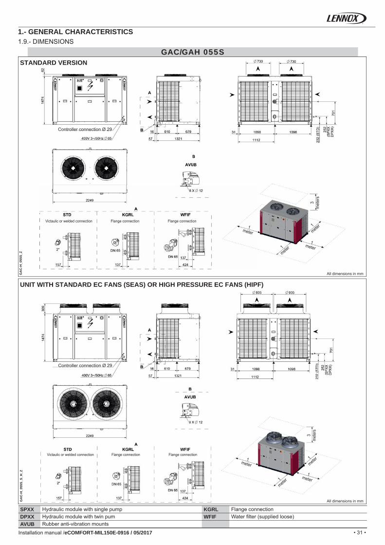
GAC/GAH 055S
SPXX KGRLDPXX WFIFAVUB
GA
C-H
_055
S_Z
GA
C-H
_055
S_S_
H_Z
Installation manual /eCOMFORT-MIL150E-0916 / 05/2017
1.- GENERAL CHARACTERISTICS1.9.- DIMENSIONS
STANDARD VERSION
UNIT WITH STANDARD EC FANS (SEAS) OR HIGH PRESSURE EC FANS (HIPF)
Hydraulic module with single pump Flange connectionHydraulic module with twin pum Water fi lter (supplied loose)Rubber anti-vibration mounts
All dimensions in mm
All dimensions in mm
3m
eter
s
3m
eter
s
1mete
r
1mete
r
1mete
r
1mete
r
1meter
1meter
1meter
1meter
Victaulic or welded connection Flange connection Flange connection
Victaulic or welded connection Flange connection Flange connection
Controller connection Ø 29
Controller connection Ø 29
• 32 •
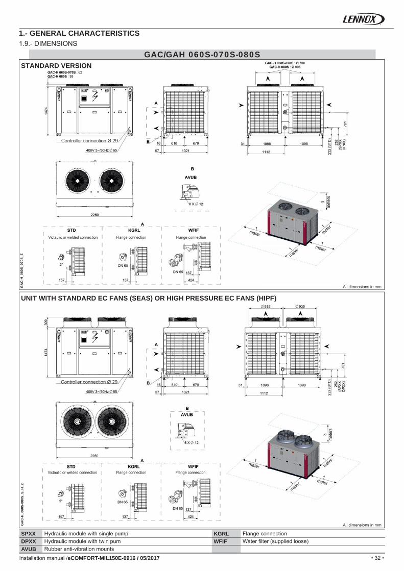
GAC/GAH 060S-070S-080S
SPXX KGRLDPXX WFIFAVUB
GA
C-H
_060
S_07
0S_Z
GA
C-H
_060
S-08
0S_S
_H_Z
Installation manual /eCOMFORT-MIL150E-0916 / 05/2017
1.- GENERAL CHARACTERISTICS1.9.- DIMENSIONS
STANDARD VERSION
UNIT WITH STANDARD EC FANS (SEAS) OR HIGH PRESSURE EC FANS (HIPF)
All dimensions in mm
All dimensions in mm
Controller connection Ø 29
Controller connection Ø 29
3m
eter
s
1mete
r
1mete
r1meter
1meter
3m
eter
s
1mete
r
1mete
r1meter
1meter
Victaulic or welded connection Flange connection Flange connection
Victaulic or welded connection Flange connection Flange connection
Hydraulic module with single pump Flange connectionHydraulic module with twin pum Water fi lter (supplied loose)Rubber anti-vibration mounts
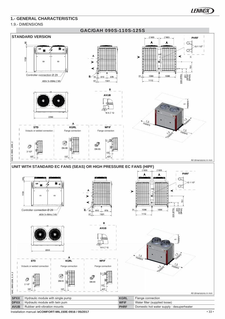
• 33 •
GAC/GAH 090S-110S-125S
SPXX KGRLDPXX WFIFAVUB PHRF
GA
C-H
_090
S_12
5S_Z
GA
C_0
90S-
125S
_S_H
_Z
Installation manual /eCOMFORT-MIL150E-0916 / 05/2017
1.- GENERAL CHARACTERISTICS1.9.- DIMENSIONS
STANDARD VERSION
UNIT WITH STANDARD EC FANS (SEAS) OR HIGH PRESSURE EC FANS (HIPF)
All dimensions in mm
All dimensions in mm
5m
eter
s
1,5
meters
1,5
meters1,5meters
1,5meters
Controller connection Ø 29
Victaulic or welded connection Flange connection Flange connection
Controller connection Ø 29
Victaulic or welded connection Flange connection Flange connection
Hydraulic module with single pump Flange connectionHydraulic module with twin pum Water fi lter (supplied loose)Rubber anti-vibration mounts Domestic hot water supply : desuperheater
5m
eter
s
1,5
meters
1,5
meters1,5meters
1,5meters
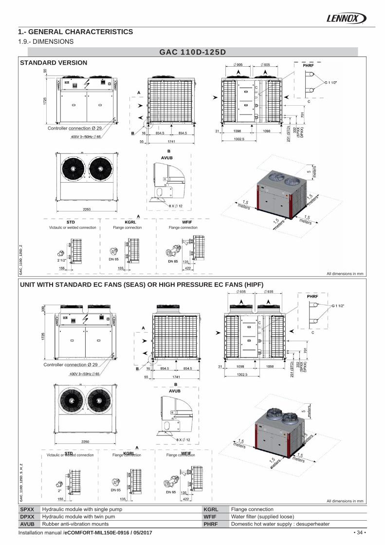
• 34 •
GAC 110D-125D
SPXX KGRLDPXX WFIFAVUB PHRF
GA
C_1
10D
_125
D_Z
GA
C_1
10D
_125
D_S
_H_Z
Installation manual /eCOMFORT-MIL150E-0916 / 05/2017
1.- GENERAL CHARACTERISTICS1.9.- DIMENSIONS
STANDARD VERSION
UNIT WITH STANDARD EC FANS (SEAS) OR HIGH PRESSURE EC FANS (HIPF)
All dimensions in mm
All dimensions in mm
Hydraulic module with single pump Flange connectionHydraulic module with twin pum Water fi lter (supplied loose)Rubber anti-vibration mounts Domestic hot water supply : desuperheater
Victaulic or welded connection Flange connection Flange connection
5m
eter
s
1,5
meters
1,5
meters
1,5meters
1,5meters
Victaulic or welded connection Flange connection Flange connection
5m
eter
s
1,5
meters
1,5
meters
1,5meters
1,5meters
Controller connection Ø 29
Controller connection Ø 29
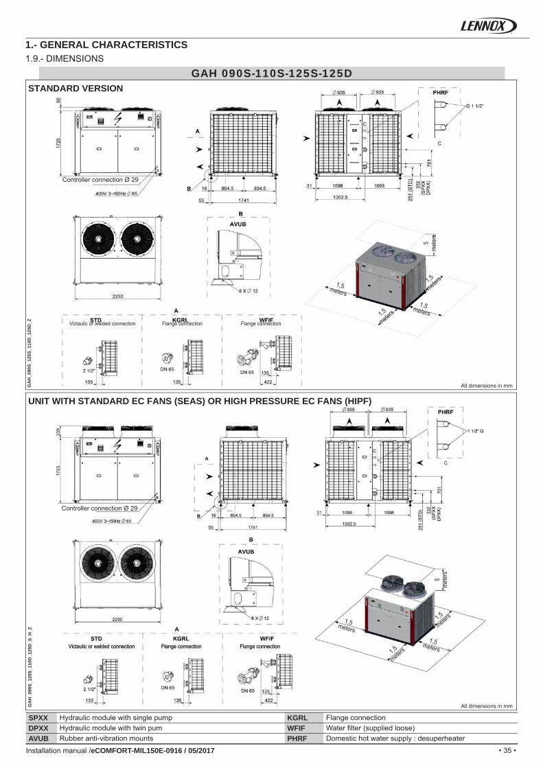
• 35 •
GAH 090S-110S-125S-125D
SPXX KGRLDPXX WFIFAVUB PHRF
GA
H_0
90S_
125S
_110
D_1
25D
_ZG
AH
_090
S_12
5S_1
10D
_125
D_S
_H_Z
Installation manual /eCOMFORT-MIL150E-0916 / 05/2017
1.- GENERAL CHARACTERISTICS1.9.- DIMENSIONS
STANDARD VERSION
UNIT WITH STANDARD EC FANS (SEAS) OR HIGH PRESSURE EC FANS (HIPF)
All dimensions in mm
All dimensions in mm
Hydraulic module with single pump Flange connectionHydraulic module with twin pum Water fi lter (supplied loose)Rubber anti-vibration mounts Domestic hot water supply : desuperheater
Victaulic or welded connection Flange connection Flange connection
5m
eter
s
1,5
meters
1,5
meters1,5meters
1,5metersVictaulic or welded connection Flange connection Flange connection
Controller connection Ø 29
Victaulic or welded connection Flange connection Flange connection
5m
eter
s
1,5
meters
1,5
meters1,5meters
1,5meters
Controller connection Ø 29
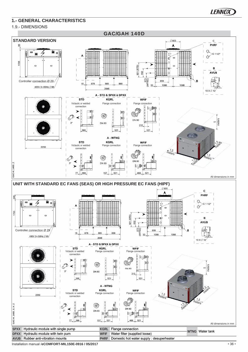
• 36 •
GAC/GAH 140D
SPXX KGRLWTNG
DPXX WFIFAVUB PHRF
GA
C-H
_140
D_Z
GA
C-H
_140
D_S
_H_Z
SPXX KGRLWTNG
DPXX WFIFAVUB PHRFInstallation manual /eCOMFORT-MIL150E-0916 / 05/2017
1.- GENERAL CHARACTERISTICS1.9.- DIMENSIONS
STANDARD VERSION
UNIT WITH STANDARD EC FANS (SEAS) OR HIGH PRESSURE EC FANS (HIPF)
All dimensions in mm
All dimensions in mm
Hydraulic module with single pump Flange connectionWater tank
Hydraulic module with twin pum Water fi lter (supplied loose)Rubber anti-vibration mounts Domestic hot water supply : desuperheater
5m
eter
s
5m
eter
s
1,5
meters
1,5
meters
1,5
meters
1,5
meters
1,5meters
1,5meters
1,5meters
1,5meters
Victaulic or welded connection
Victaulic or welded connection
Victaulic or welded connection
Victaulic or welded connection
Flange connection
Flange connection
Flange connection
Flange connection
Flange connection
Flange connection
Flange connection
Flange connection
Controller connection Ø 29
Controller connection Ø 29
Hydraulic module with single pump Flange connectionWater tank
Hydraulic module with twin pum Water fi lter (supplied loose)Rubber anti-vibration mounts Domestic hot water supply : desuperheater
• 37 •
GAC/GAH 160D - 185D
SPXX KGRLWTNG
DPXX WFIFAVUB PHRF
GA
C-H
_160
D_1
85D
_ZG
AC
-H_1
60D
_185
D_S
_H_Z
Installation manual /eCOMFORT-MIL150E-0916 / 05/2017
1.- GENERAL CHARACTERISTICS1.9.- DIMENSIONS
STANDARD VERSION
UNIT WITH STANDARD EC FANS (SEAS) OR HIGH PRESSURE EC FANS (HIPF)
All dimensions in mm
All dimensions in mm
Hydraulic module with single pump Flange connectionWater tank
Hydraulic module with twin pum Water fi lter (supplied loose)Rubber anti-vibration mounts Domestic hot water supply : desuperheater
5m
eter
s
1,5
meters
1,5
meters
1,5meters
1,5metersVictaulic or welded
connection
Victaulic or welded connection
Flange connection
Flange connection
Flange connection
Flange connection
Controller connection Ø 29
5m
eter
s
1,5
meters
1,5
meters
1,5meters
1,5meters
Victaulic or welded connection
Victaulic or welded connection
Flange connection
Flange connection
Flange connection
Flange connection
Controller connection Ø 29
• 38 •Installation manual /eCOMFORT-MIL150E-0916 / 05/2017
2.1 TRANSPORT - HANDLING
Equipment designed to withstand transport and handling according to the established protocol (for the handling protocol, please refer to the installation instructions for the relevant product range). All unloading operations must be carried out with suitable equipment (crane, forklift truck, etc.).Optional removable handling rings are available for certain products.When using a forklift truck, you must respect the positions and the direction of handling indicated on the products.The equipment must be handled with care to avoid damage to the bodywork, pipework, condenser, etc.
Controls and delivery checksAfter the unit has been received, when it is ready to be installed or reinstalled, and before it is started up, it must be inspected for damage. On receipt of anew equipment please check the following points. It is the customer’s responsibility to ensure that the products are in good working order (fi ll the check list page 62):The exterior has not been damaged in any way.The lifting and handling equipment are suitable for the equipment and comply with the specifi cations of the handling instructions enclo-sed here-in.Accessories ordered for on site installation have been delivered and are in good working order.If the unit is delivered with its operating charge of refrigerant, that there has been no leakage (use an electronic detector).The equipment supplied corresponds to the order and matches the delivery note.
If the product is damaged, exact details must be confi rmed in writing by registered post to the shipping company within 48 hours of delivery (working days).
A copy of the letter must be addressed to LENNOX and the supplier or distributor for information purposes. Failure to comply will invalidate any claim against the shipping company.Please be reminded that LENNOX is not responsible for off-loading and positioning.
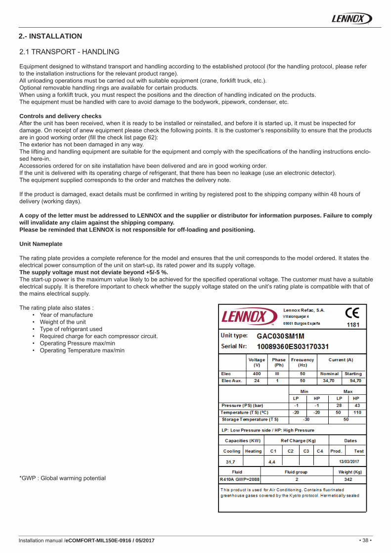
Unit Nameplate
The rating plate provides a complete reference for the model and ensures that the unit corresponds to the model ordered. It states the electrical power consumption of the unit on start-up, its rated power and its supply voltage.The supply voltage must not deviate beyond +5/-5 %.The start-up power is the maximum value likely to be achieved for the specifi ed operational voltage. The customer must have a suitable electrical supply. It is therefore important to check whether the supply voltage stated on the unit’s rating plate is compatible with that of the mains electrical supply.
The rating plate also states :• Year of manufacture • Weight of the unit• Type of refrigerant used • Required charge for each compressor circuit.• Operating Pressure max/min• Operating Temperature max/min
*GWP : Global warming potential
2.- INSTALLATION
• 39 •Installation manual /eCOMFORT-MIL150E-0916 / 05/2017
2.- INSTALLATIONWhen unpacking the machine, have a correct segregation of non-hazardous waste coming from packaging: Plastic fi lm or other plastic elements, metal strips, wood and pallets, through authorized dealers, or segregatethem in the containers destined for this purposeFollow the installation instructions established in this manual to avoid disturbing noise caused by movement or shocks due to defi cient installation of the unit.
2.2.- SITE AND SHIPPING GUIDANCE
All INSTALATION, SERVICE, and MAINTENANCE operations must be carried out by QUALIFIED PERSONNEL
The unit must be transported in a HORIZONTAL POSITION on its wooden pallet. Any other position may cause serious damage to the machine.When the unit is received, it should be checked to assure that there are no bumps or other damage, following the instructions on the packaging. If there is damage, the unit may be rejected by notifying the LENNOX Distribution Deparent and reporting why the machine is unacceptable on the transport agent’s delivery notice. Any later complaint or claim made to the LENNOX Distribution Deparent, for this type of anomaly, cannot be considered under the Guarantee.
Suffi cient space must be allowed to facilitate placement of the unit. The unit may be mounted outdoors. There should be adequate drainage around the unit.
In heat pump units during defrost cycle, the units produce a great amount of water melting the ice off coils.If you wish to drain the water, adequate drainage should be installed behind the unit to collect and carry out the water where desired.
When positioning the unit, be sure that the Rating Plate will always be visible since this data will be necessary to assure proper maintenance.
It is advisable to unpack the unit at the place where the unit is going to be installed, to avoid damages during manage.
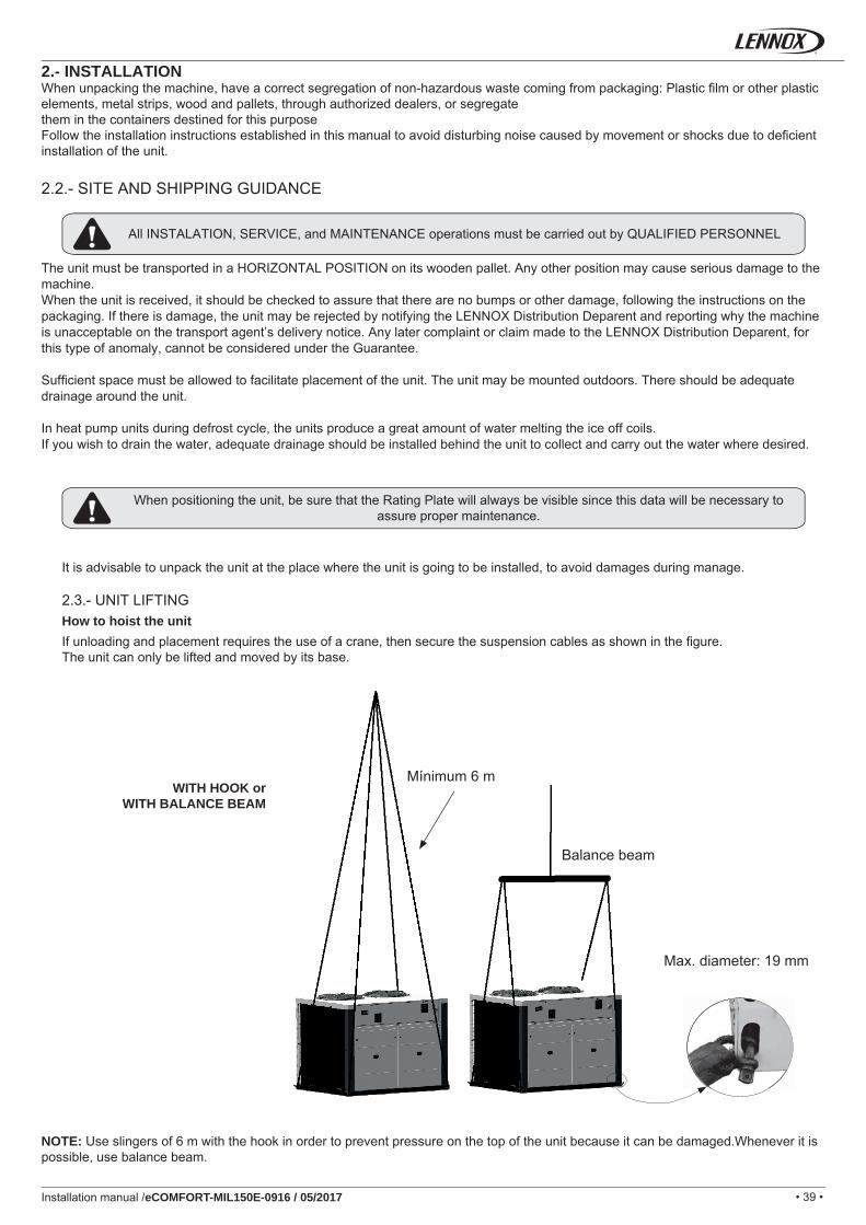
2.3.- UNIT LIFTINGHow to hoist the unitIf unloading and placement requires the use of a crane, then secure the suspension cables as shown in the fi gure.The unit can only be lifted and moved by its base.
NOTE: Use slingers of 6 m with the hook in order to prevent pressure on the top of the unit because it can be damaged.Whenever it is possible, use balance beam.
WITH HOOK or WITH BALANCE BEAM
Mínimum 6 m
Balance beam
Max. diameter: 19 mm
• 40 •Installation manual /eCOMFORT-MIL150E-0916 / 05/2017
Unit
Flexible connection
Rubber mounting
Flexible connection with loop
Damping spring
Metallic structureSupport
Rubber mounting
Flexible connection with loop
Damping spring
Metallic and concrete structure
Support
Rubber mounting
Unit
Unit
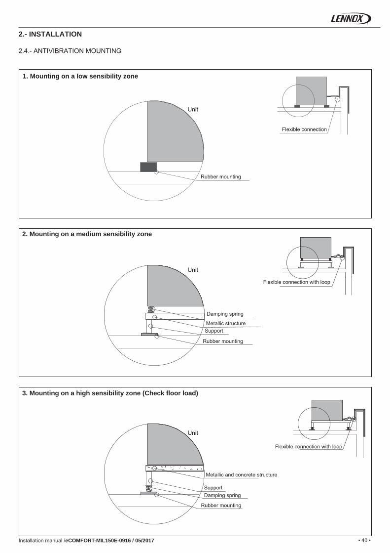
1. Mounting on a low sensibility zone
2. Mounting on a medium sensibility zone
3. Mounting on a high sensibility zone (Check fl oor load)
2.- INSTALLATION
2.4.- ANTIVIBRATION MOUNTING
• 41 •
2242
1315
1098 1098
12
610
679
610
679
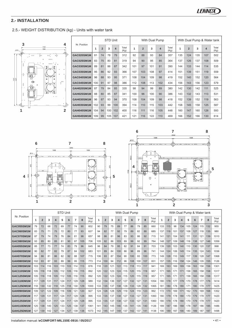
1 2 3 4 1 2 3 4 1 2 3 4
GAC020SM1M 81 74 78 79 312 92 88 93 84 357 135 124 135 107 502
GAC025SM1M 83 75 80 81 319 94 90 95 85 364 137 126 137 108 509
GAC030SM1M 89 81 86 87 342 101 97 101 91 390 144 133 144 114 535
GAC035SM1M 95 86 92 93 366 107 103 108 97 414 151 139 151 119 559
GAC040SM1M 96 88 93 95 371 108 104 109 98 419 152 140 152 120 564
GAC045SM1M 100 91 97 98 386 112 108 113 102 434 156 143 156 123 579
GAH020SM1M 87 79 84 85 335 98 94 99 89 380 142 130 142 111 525
GAH025SM1M 88 80 85 87 341 100 96 100 90 386 143 132 143 113 531
GAH030SM1M 96 87 93 94 370 108 104 109 98 418 152 139 152 119 563
GAH035SM1M 102 93 99 100 394 114 110 115 103 442 158 145 158 125 587
GAH040SM1M 104 94 100 102 400 116 111 116 105 448 160 147 160 126 593
GAH045SM1M 109 99 105 107 421 121 116 122 110 469 166 152 166 130 614
11221082
1317
1277
12
1098 109812
2242
1735
854,
585
4,5
1 2 3 4 5 6 7 8 1 2 3 4 5 6 7 8 1 2 3 4 5 6 7 8
GAC055SM1M 79 72 68 72 69 77 74 90 602 90 79 75 89 77 86 79 85 660 133 115 98 134 105 124 115 132 955
GAC060SM1M 83 75 71 75 72 80 77 93 627 94 82 77 92 79 89 82 88 685 137 118 101 137 108 127 118 135 980
GAC070SM1M 87 79 74 79 76 84 81 98 657 98 86 81 96 83 93 86 92 715 141 121 104 141 111 131 121 139 1010
GAC080SM1M 93 85 80 85 81 90 87 105 706 105 92 86 103 89 99 92 99 764 148 127 109 148 116 138 127 146 1059
GAH055SM1M 85 77 73 77 74 83 79 96 645 96 84 79 95 82 91 84 91 703 139 120 103 140 110 130 120 137 998
GAH060SM1M 90 82 77 82 79 87 84 102 683 101 89 84 100 86 96 89 96 741 144 124 106 145 114 135 124 143 1036
GAH070SM1M 94 86 81 86 82 92 88 107 715 106 93 87 104 90 100 93 100 773 149 128 110 149 117 139 128 147 1068
GAH080SM1M 102 93 87 93 89 99 95 115 773 114 100 94 112 96 108 100 107 831 157 135 116 158 124 146 135 155 1126
GAC090SM1M 103 114 116 103 110 103 114 113 876 118 120 121 122 113 118 113 117 941 169 163 169 169 156 163 156 156 1301
GAC110SM1M 105 116 118 105 112 105 116 115 892 120 122 123 124 115 120 115 119 957 171 165 171 171 158 165 158 158 1317
GAC125SM1M 105 116 118 105 112 105 116 115 892 120 122 123 124 115 120 115 119 957 171 165 171 171 158 165 158 158 1317
GAC110DM1M 117 129 131 117 124 117 129 128 989 132 134 136 137 127 132 127 131 1054 180 178 177 179 170 178 177 176 1414
GAC125DM1M 118 130 132 118 125 118 130 129 1000 133 135 137 138 128 133 128 132 1065 181 180 178 180 171 180 178 177 1425
GAH090SM1M 109 121 122 109 116 109 121 120 927 124 126 128 129 119 124 119 123 992 172 170 169 171 162 170 169 168 1352
GAH110SM1M 117 129 131 117 124 117 129 128 995 133 135 137 138 127 133 127 131 1060 180 179 178 180 170 179 178 177 1420
GAH125SM1M 117 129 131 117 124 117 129 128 995 133 135 137 138 127 133 127 131 1060 180 179 178 180 170 179 178 177 1420
GAH110DM1M 125 138 140 125 133 125 138 137 1061 141 143 145 146 135 141 135 140 1126 189 187 186 188 178 187 186 185 1486
GAH125DM1M 127 139 142 127 134 127 139 138 1073 142 145 147 148 137 142 137 141 1138 190 189 187 190 180 189 187 187 1498
3
21
4
6
54
87
1 32
6
54
87
1 32
Installation manual /eCOMFORT-MIL150E-0916 / 05/2017
2.5.- WEIGHT DISTRIBUTION (kg) - Units with water tank
2.- INSTALLATION
Nr. Position
STD Unit With Dual Pump With Dual Pump & Water tank
Total (Kg)
Total (Kg)
Total (Kg)
Nr. PositionSTD Unit With Dual Pump With Dual Pump & Water tank
Total (Kg)
Total (Kg)
Total (Kg)
• 42 •
1098 1098
878
869
869
2242
2642
878
869
869
12
1 2 3 4 5 6 7 8 9 10
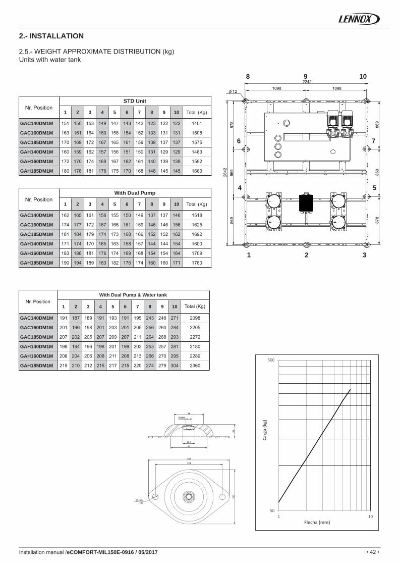
GAC140DM1M 151 150 153 149 147 143 142 123 122 122 1401
GAC160DM1M 163 161 164 160 158 154 152 133 131 131 1508
GAC185DM1M 170 169 172 167 165 161 159 139 137 137 1575
GAH140DM1M 160 159 162 157 156 151 150 131 129 129 1483
GAH160DM1M 172 170 174 169 167 162 161 140 139 139 1592
GAH185DM1M 180 178 181 176 175 170 168 146 145 145 1663
1 2 3 4 5 6 7 8 9 10
GAC140DM1M 162 165 161 156 155 150 149 137 137 146 1518
GAC160DM1M 174 177 172 167 166 161 159 146 146 156 1625
GAC185DM1M 181 184 179 174 173 168 166 152 152 162 1692
GAH140DM1M 171 174 170 165 163 158 157 144 144 154 1600
GAH160DM1M 183 186 181 176 174 169 168 154 154 164 1709
GAH185DM1M 190 194 189 183 182 176 174 160 160 171 1780
1 2 3 4 5 6 7 8 9 10
GAC140DM1M 191 187 189 191 193 191 195 243 248 271 2098
GAC160DM1M 201 196 198 201 203 201 205 256 260 284 2205
GAC185DM1M 207 202 205 207 209 207 211 264 268 293 2272
GAH140DM1M 198 194 196 198 201 198 203 253 257 281 2180
GAH160DM1M 208 204 206 208 211 208 213 266 270 295 2289
GAH185DM1M 215 210 212 215 217 215 220 274 279 304 2360
8
76
109
1 32
54
50
500
1 10
Carg
a (k
g)
Flecha (mm)
Installation manual /eCOMFORT-MIL150E-0916 / 05/2017
2.5.- WEIGHT APPROXIMATE DISTRIBUTION (kg)Units with water tank
2.- INSTALLATION
Nr. PositionSTD Unit
Total (Kg)
Nr. PositionWith Dual Pump
Total (Kg)
Nr. PositionWith Dual Pump & Water tank
Total (Kg)
• 43 •
GA
C/G
AH
06
0S-0
70S
-080
SG
AC
03
0S-1
10S
-125
SG
AC
/GA
H
020S
-025
S-0
35S
-045
SG
AC
/GA
H
055S
Installation manual /eCOMFORT-MIL150E-0916 / 05/2017
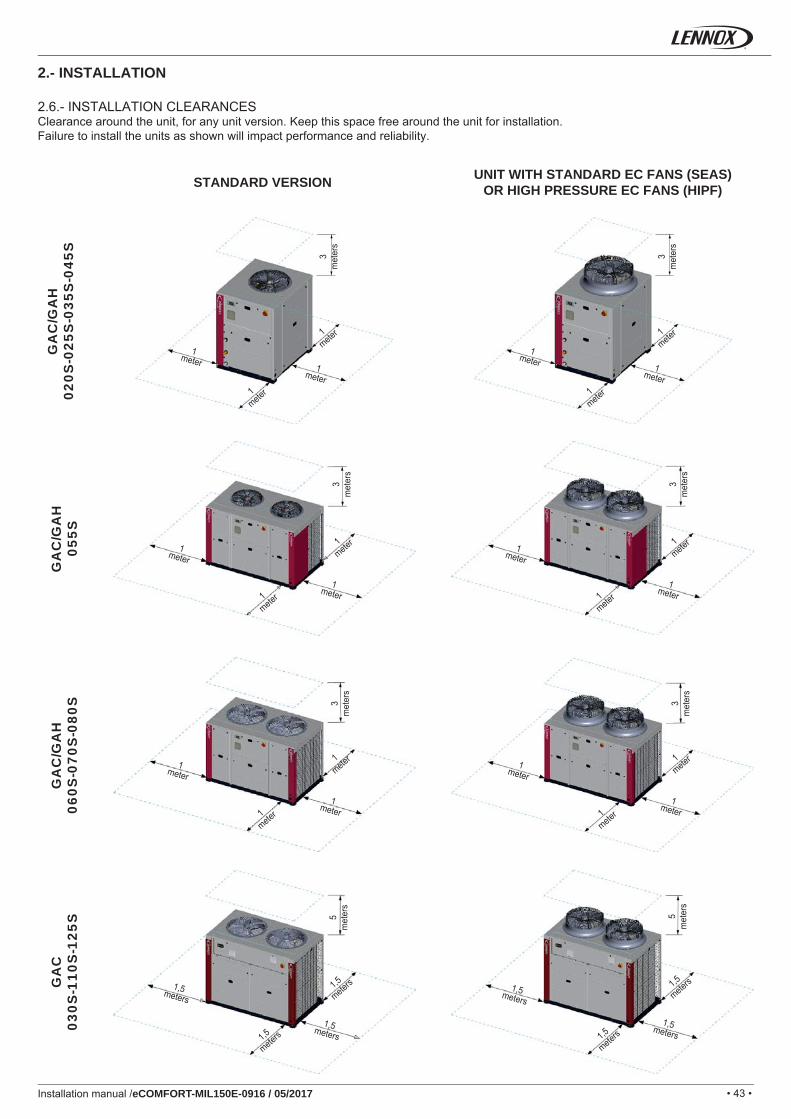
2.- INSTALLATION
2.6.- INSTALLATION CLEARANCESClearance around the unit, for any unit version. Keep this space free around the unit for installation.Failure to install the units as shown will impact performance and reliability.
3m
eter
s
3m
eter
s3
met
ers
3m
eter
s3
met
ers
5m
eter
s
5m
eter
s3
met
ers
1mete
r 1mete
r
1mete
r1mete
r
1mete
r
1,5
meters 1,5
meters
1mete
r
1mete
r 1mete
r
1mete
r1mete
r
1mete
r
1,5
meters 1,5
meters
1mete
r
1meter
1meter
1meter
1meter
1meter
1,5meters1,5meters
1meter
1meter
1meter
1meter
1meter
1meter
1,5meters1,5meters
1meter
STANDARD VERSION UNIT WITH STANDARD EC FANS (SEAS) OR HIGH PRESSURE EC FANS (HIPF)
• 44 •
GA
C 1
10D
-125
D G
AH
09
0S-1
25S
GA
C/G
AH
14
0DG
AC
/GA
H
160D
-185
D
Installation manual /eCOMFORT-MIL150E-0916 / 05/2017
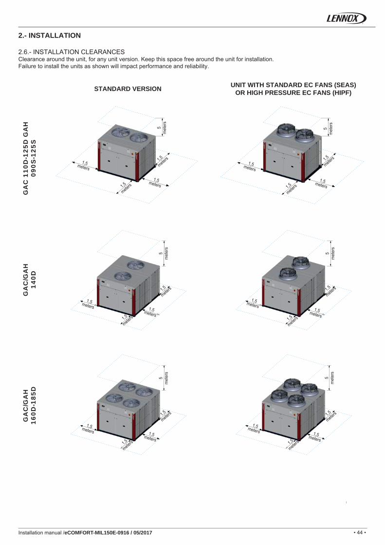
2.- INSTALLATION
2.6.- INSTALLATION CLEARANCESClearance around the unit, for any unit version. Keep this space free around the unit for installation.Failure to install the units as shown will impact performance and reliability.
STANDARD VERSION UNIT WITH STANDARD EC FANS (SEAS) OR HIGH PRESSURE EC FANS (HIPF)
5m
eter
s
5m
eter
s
1,5
meters 1,5
meters
1,5
meters 1,5
meters
1,5meters1,5meters
1,5meters1,5meters
5m
eter
s5
met
ers
5m
eter
s
1,5
meters
1,5
meters 1,5
meters
1,5
meters
1,5
meters 1,5
meters
1,5meters
1,5meters1,5meters
1,5meters
1,5meters1,5meters
5m
eter
s
1,5
meters
1,5
meters
1,5meters1,5meters
• 45 •Installation manual /eCOMFORT-MIL150E-0916 / 05/2017
Air outletAir outlet duct
Unit
Air inlet duct
Air inlet
WARNINGIf the unit is exposed for long periods to installation conditions below 0ºC the water from defrost can freeze in the base of the unit. This prevents drainage. Ice build up can occur preventing correct operation. For these conditions contact customer service team.
6. The heat exchanger water fl ow during cooling must be the same as during heating.7. The use of a water fi lter in the water circuit upstream of the heat exchanger is mandatory. These fi lters must remove all
particles with a diameter greater than 1 mm, and must be positioned within 1 meter of the inlet of the exchanger. They may be supplied as an option by the manufacturer.
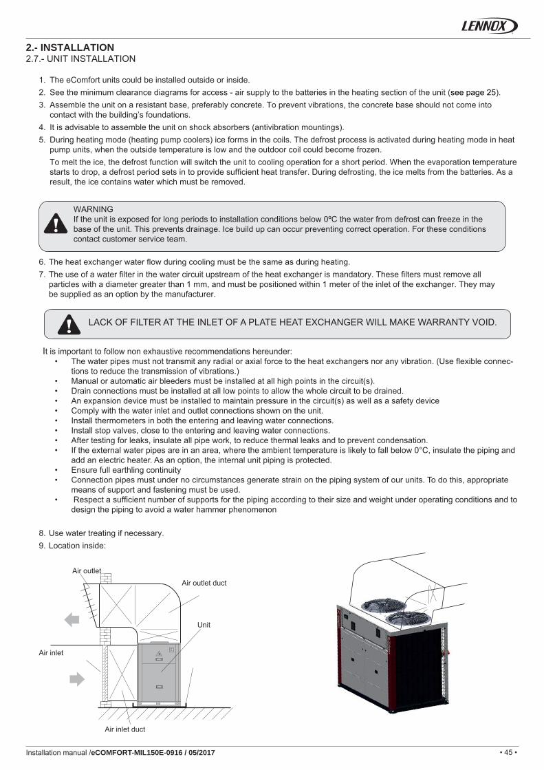
8. Use water treating if necessary.9. Location inside:
2.- INSTALLATION2.7.- UNIT INSTALLATION
1. The eComfort units could be installed outside or inside.2. See the minimum clearance diagrams for access - air supply to the batteries in the heating section of the unit (see page 25).3. Assemble the unit on a resistant base, preferably concrete. To prevent vibrations, the concrete base should not come into
contact with the building’s foundations.4. It is advisable to assemble the unit on shock absorbers (antivibration mountings).5. During heating mode (heating pump coolers) ice forms in the coils. The defrost process is activated during heating mode in heat
pump units, when the outside temperature is low and the outdoor coil could become frozen. To melt the ice, the defrost function will switch the unit to cooling operation for a short period. When the evaporation temperature
starts to drop, a defrost period sets in to provide suffi cient heat transfer. During defrosting, the ice melts from the batteries. As a result, the ice contains water which must be removed.
LACK OF FILTER AT THE INLET OF A PLATE HEAT EXCHANGER WILL MAKE WARRANTY VOID.
It is important to follow non exhaustive recommendations hereunder:• The water pipes must not transmit any radial or axial force to the heat exchangers nor any vibration. (Use fl exible connec-
tions to reduce the transmission of vibrations.)• Manual or automatic air bleeders must be installed at all high points in the circuit(s).• Drain connections must be installed at all low points to allow the whole circuit to be drained.• An expansion device must be installed to maintain pressure in the circuit(s) as well as a safety device• Comply with the water inlet and outlet connections shown on the unit.• Install thermometers in both the entering and leaving water connections.• Install stop valves, close to the entering and leaving water connections.• After testing for leaks, insulate all pipe work, to reduce thermal leaks and to prevent condensation.• If the external water pipes are in an area, where the ambient temperature is likely to fall below 0°C, insulate the piping and
add an electric heater. As an option, the internal unit piping is protected.• Ensure full earthling continuity• Connection pipes must under no circumstances generate strain on the piping system of our units. To do this, appropriate
means of support and fastening must be used. • Respect a suffi cient number of supports for the piping according to their size and weight under operating conditions and to
design the piping to avoid a water hammer phenomenon
• 46 •
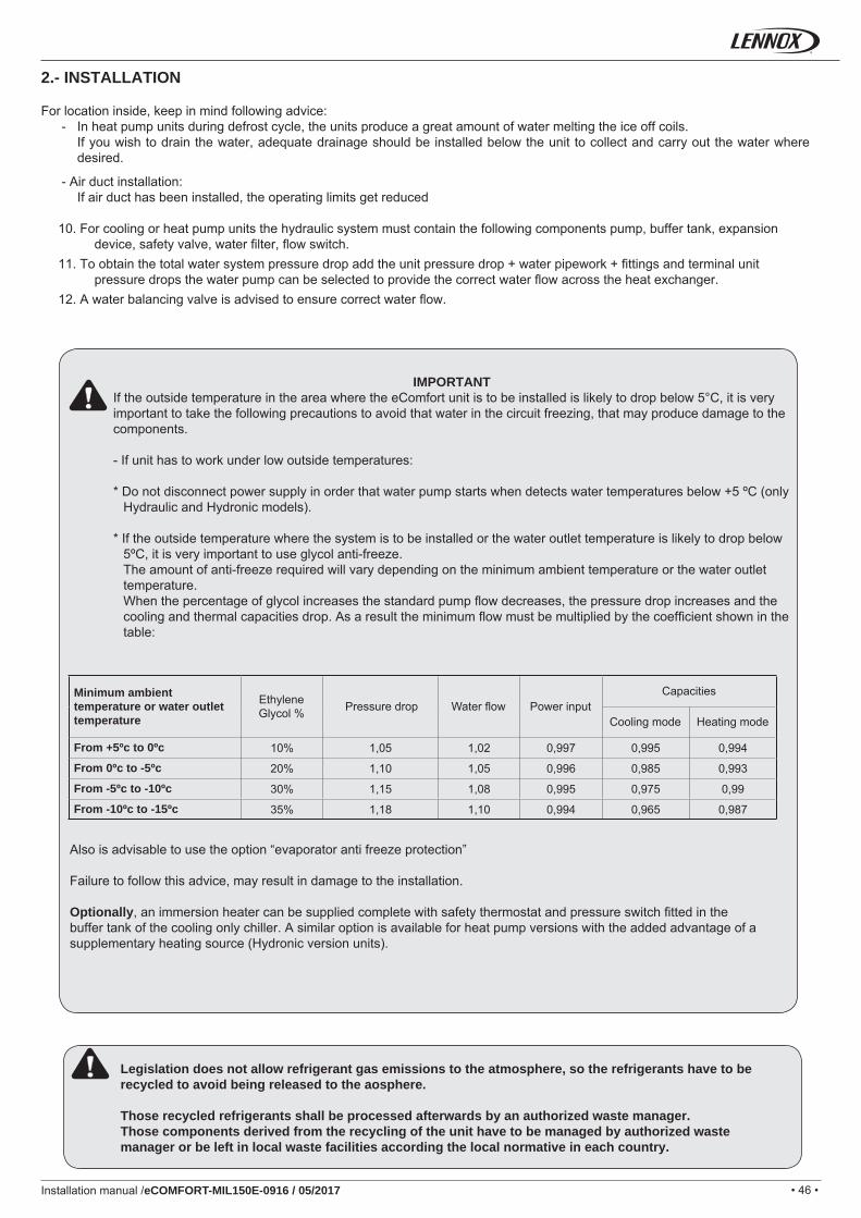
10% 1,05 1,02 0,997 0,995 0,994
20% 1,10 1,05 0,996 0,985 0,993
30% 1,15 1,08 0,995 0,975 0,99
35% 1,18 1,10 0,994 0,965 0,987
Installation manual /eCOMFORT-MIL150E-0916 / 05/2017
Minimum ambient temperature or water outlet temperature
Ethylene Glycol % Pressure drop Water fl ow Power input
Capacities
Cooling mode Heating mode
From +5ºc to 0ºc
From 0ºc to -5ºc
From -5ºc to -10ºc
From -10ºc to -15ºc
IMPORTANTIf the outside temperature in the area where the eComfort unit is to be installed is likely to drop below 5°C, it is very important to take the following precautions to avoid that water in the circuit freezing, that may produce damage to the components.
- If unit has to work under low outside temperatures:
* Do not disconnect power supply in order that water pump starts when detects water temperatures below +5 ºC (only Hydraulic and Hydronic models).
* If the outside temperature where the system is to be installed or the water outlet temperature is likely to drop below 5ºC, it is very important to use glycol anti-freeze.The amount of anti-freeze required will vary depending on the minimum ambient temperature or the water outlet temperature.When the percentage of glycol increases the standard pump fl ow decreases, the pressure drop increases and the cooling and thermal capacities drop. As a result the minimum fl ow must be multiplied by the coeffi cient shown in the table:
Also is advisable to use the option “evaporator anti freeze protection”
Failure to follow this advice, may result in damage to the installation.
Optionally, an immersion heater can be supplied complete with safety thermostat and pressure switch fi tted in the buffer tank of the cooling only chiller. A similar option is available for heat pump versions with the added advantage of a supplementary heating source (Hydronic version units).
2.- INSTALLATION
Legislation does not allow refrigerant gas emissions to the atmosphere, so the refrigerants have to be recycled to avoid being released to the aosphere.
Those recycled refrigerants shall be processed afterwards by an authorized waste manager.Those components derived from the recycling of the unit have to be managed by authorized waste manager or be left in local waste facilities according the local normative in each country.
For location inside, keep in mind following advice: - In heat pump units during defrost cycle, the units produce a great amount of water melting the ice off coils. If you wish to drain the water, adequate drainage should be installed below the unit to collect and carry out the water where
desired.
- Air duct installation: If air duct has been installed, the operating limits get reduced
10. For cooling or heat pump units the hydraulic system must contain the following components pump, buffer tank, expansion device, safety valve, water fi lter, fl ow switch.
11. To obtain the total water system pressure drop add the unit pressure drop + water pipework + fi ttings and terminal unit pressure drops the water pump can be selected to provide the correct water fl ow across the heat exchanger.
12. A water balancing valve is advised to ensure correct water fl ow.
• 47 •
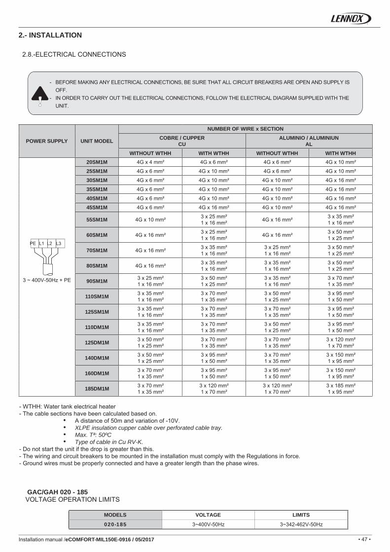
020-185 3~400V-50Hz 3~342-462V-50Hz
PE L1 L2 L3
GAC/GAH 020 - 185
3 ~ 400V-50Hz + PE
20SM1M 4G x 4 mm² 4G x 6 mm² 4G x 6 mm² 4G x 10 mm²
25SM1M 4G x 6 mm² 4G x 10 mm² 4G x 6 mm² 4G x 10 mm²
30SM1M 4G x 6 mm² 4G x 10 mm² 4G x 10 mm² 4G x 16 mm²
35SM1M 4G x 6 mm² 4G x 10 mm² 4G x 10 mm² 4G x 16 mm²
40SM1M 4G x 6 mm² 4G x 10 mm² 4G x 10 mm² 4G x 16 mm²
45SM1M 4G x 6 mm² 4G x 16 mm² 4G x 10 mm² 4G x 16 mm²
55SM1M 4G x 10 mm² 3 x 25 mm²1 x 16 mm² 4G x 16 mm² 3 x 35 mm²
1 x 16 mm²
60SM1M 4G x 16 mm² 3 x 25 mm²1 x 16 mm² 4G x 16 mm² 3 x 50 mm²
1 x 25 mm²
70SM1M 4G x 16 mm² 3 x 35 mm²1 x 16 mm²
3 x 25 mm²1 x 16 mm²
3 x 50 mm²1 x 25 mm²
80SM1M 4G x 16 mm² 3 x 35 mm²1 x 16 mm²
3 x 35 mm²1 x 16 mm²
3 x 50 mm²1 x 25 mm²
90SM1M 3 x 25 mm²1 x 16 mm²
3 x 50 mm²1 x 25 mm²
3 x 35 mm²1 x 16 mm²
3 x 70 mm²1 x 35 mm²
110SM1M 3 x 35 mm²1 x 16 mm²
3 x 70 mm²1 x 35 mm²
3 x 50 mm²1 x 25 mm²
3 x 95 mm²1 x 50 mm²
125SM1M 3 x 35 mm²1 x 16 mm²
3 x 70 mm²1 x 35 mm²
3 x 70 mm²1 x 35 mm²
3 x 95 mm²1 x 50 mm²
110DM1M 3 x 35 mm²1 x 16 mm²
3 x 70 mm²1 x 35 mm²
3 x 50 mm²1 x 25 mm²
3 x 95 mm²1 x 50 mm²
125DM1M 3 x 50 mm²1 x 25 mm²
3 x 70 mm²1 x 35 mm²
3 x 70 mm²1 x 35 mm²
3 x 120 mm²1 x 70 mm²
140DM1M 3 x 50 mm²1 x 25 mm²
3 x 95 mm²1 x 50 mm²
3 x 70 mm²1 x 35 mm²
3 x 150 mm²1 x 95 mm²
160DM1M 3 x 70 mm²1 x 35 mm²
3 x 95 mm²1 x 50 mm²
3 x 95 mm²1 x 50 mm²
3 x 150 mm²1 x 95 mm²
185DM1M 3 x 70 mm²1 x 35 mm²
3 x 120 mm²1 x 70 mm²
3 x 120 mm²1 x 70 mm²
3 x 185 mm²1 x 95 mm²
Installation manual /eCOMFORT-MIL150E-0916 / 05/2017
2.8.-ELECTRICAL CONNECTIONS
- BEFORE MAKING ANY ELECTRICAL CONNECTIONS, BE SURE THAT ALL CIRCUIT BREAKERS ARE OPEN AND SUPPLY IS OFF.
- IN ORDER TO CARRY OUT THE ELECTRICAL CONNECTIONS, FOLLOW THE ELECTRICAL DIAGRAM SUPPLIED WITH THE UNIT.
- WTHH: Water tank electrical heater- The cable sections have been calculated based on.
• A distance of 50m and variation of -10V.• XLPE insulation cupper cable over perforated cable tray.• Max. Tª: 50ºC• Type of cable in Cu RV-K.
- Do not start the unit if the drop is greater than this.- The wiring and circuit breakers to be mounted in the installation must comply with the Regulations in force.- Ground wires must be properly connected and have a greater length than the phase wires.
VOLTAGE OPERATION LIMITS
MODELS VOLTAGE LIMITS
2.- INSTALLATION
POWER SUPPLY UNIT MODEL
NUMBER OF WIRE x SECTIONCOBRE / CUPPER
CUALUMINIO / ALUMINIUN
ALWITHOUT WTHH WITH WTHH WITHOUT WTHH WITH WTHH
• 48 •
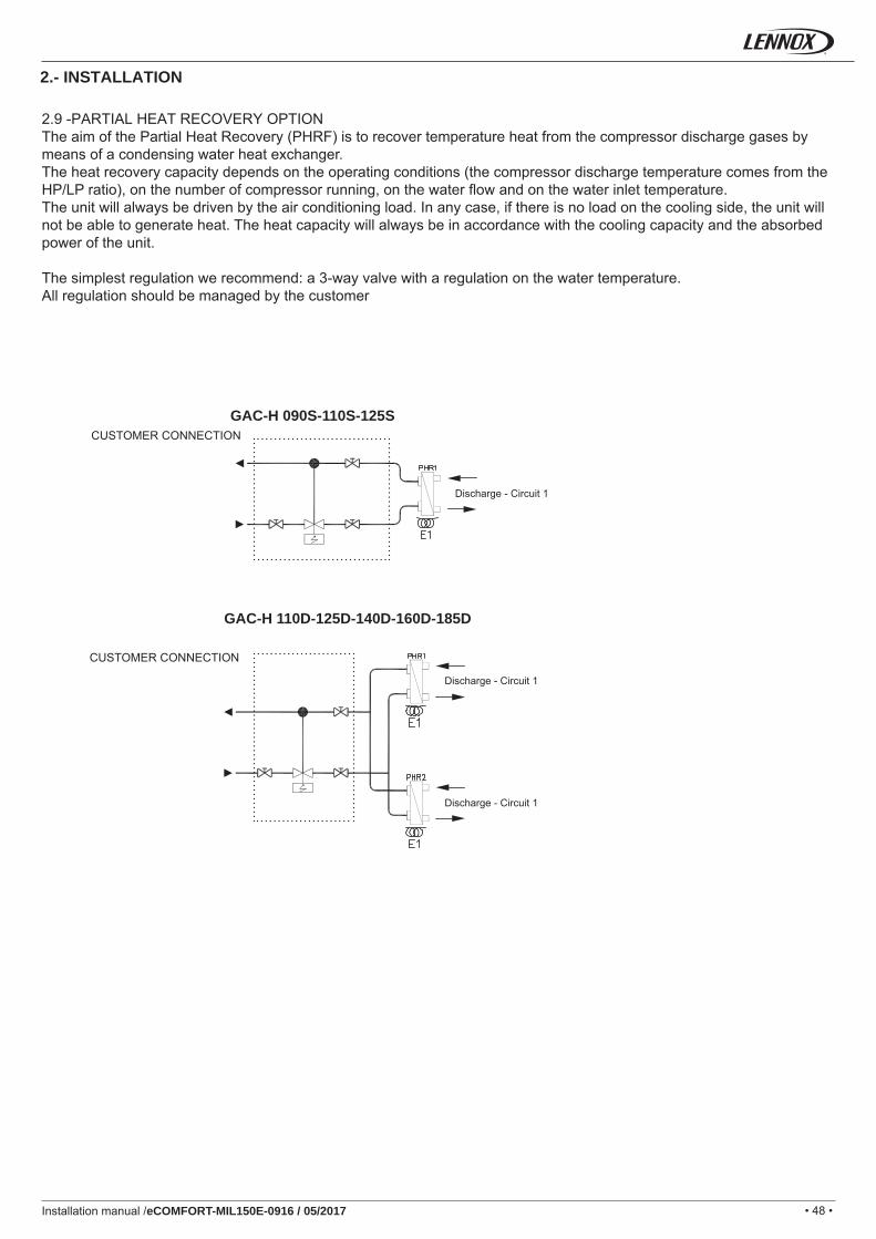
GAC-H 090S-110S-125S
GAC-H 110D-125D-140D-160D-185D
Installation manual /eCOMFORT-MIL150E-0916 / 05/2017
2.- INSTALLATION
2.9 -PARTIAL HEAT RECOVERY OPTION The aim of the Partial Heat Recovery (PHRF) is to recover temperature heat from the compressor discharge gases by means of a condensing water heat exchanger.The heat recovery capacity depends on the operating conditions (the compressor discharge temperature comes from the HP/LP ratio), on the number of compressor running, on the water fl ow and on the water inlet temperature.The unit will always be driven by the air conditioning load. In any case, if there is no load on the cooling side, the unit will not be able to generate heat. The heat capacity will always be in accordance with the cooling capacity and the absorbed power of the unit.
The simplest regulation we recommend: a 3-way valve with a regulation on the water temperature. All regulation should be managed by the customer
CUSTOMER CONNECTION
CUSTOMER CONNECTION
Discharge - Circuit 1
Discharge - Circuit 1
Discharge - Circuit 1
• 49 •Installation manual /eCOMFORT-MIL150E-0916 / 05/2017
3.- COMMISSIONING AND OPERATION
REMEMBER THAT THE COMPRESSOR IS A SCROLL TYPE COMPRESSOR:
Before starting the unit, the compressor should be checked that rotates in the correct direction, through a three phase protection. Scroll type compressors only compress in one direction of the rotation. Therefore, it is essential that the phase connection for scroll-type three-phase compressors be carried out correctly (the correct direction of rotation can be checked when the pressure on the suction side decreases and the pressure on the discharge side increases when the compressor is activated). If the connection is wrong, the rotation will be reversed causing a high noise level and a reduction in the amount of current consumed. If this occurs, the compressor’s internal protection system will operate in shutting down the unit. The solution is to disconnect, switch the wires between two of the phases and connect the three again).
- Occasionally, when compressor stops and starts, there is a metallic noise because of spirals of the compressor. This is normal.- Check compressor oil level, sight glass included (on the sides of the compressor, the level should be between 1/4 and 3/4 in the sight glass, while during operation the level should be between 3/4 and full).- Check that operating pressure values are normal.- Measure electrical consumption for the unit.- Check the electrical consumption of the compressor and the fans with what is specifi ed in the physical data sheets.- In the case of a Heat Pump unit, make a cycle change checking that the 4-way valve makes the change correctly. Check the pressure values in the new cycle.
LENNOX REFAC, S.A. Designs and develops its machines always looking for the greater comfort and well-being of its custo-mers and users, at the same time as the greater energy effi ciency of the elements that constitute the units. This effort would be fruitless if it was not united to a responsible use of these equipment. For this reason, we invite you to use these machines in a responsible way with the environment, combining the adequate comfort, with a responsible consumption of the energy resources.
3.1.- STEPS TO FOLLOW FOR COMMISSIONING THE UNITS
Before commissioning the unit check the following:1. Check that the voltage is the same as the rated voltage on the specifi cation plate.2. Check that the supply to the control system is connected in accordance with the electrical diagram (if incorporates)3. Make sure that the water connections are correct and have not been altered, as this can result in incorrect operation the fl ow divider will not operate if the connections are mixe.
4. Check that the main switch is ON.5. The compressor must not be started until the crankcase heater has been running for at least 8 hours.6. Check the water pump’s direction of rotation.7. Check for air in the water system. Purge if necessary.8. Check that the fan can rotate freely.
- The compressor has an electric heating element to assure a separation between the Refrigerant and the oil in the housing. This heater is activated when the compressor is off and stops working when the compressor is on.About eight hours before start up or after a long shutdown period, voltage should be supplied to the unit and main switch activated in order to this heater will be activated.
- Check that the compressor starts after several minutes since water pump is working.- Adjust the control to select the operating mode.
- Water connections: before running the unit for the fi rst time, check that the water circuits are connected to the heat exchangers (for example, no inversion between evaporator and condenser or between the water inlets and outlets. Waer pump will be preferably upstream, so the evaporator/condenser will be under possitive pressure. Water inlet and outlet connections are indicated in the certifi ed scheme sent with the unit or depicted in the manual. A fi lter must be installed in the water circuit upstream the heat exchanger. This fi lters must stop all the particles higher than 1 mm in diameter and must be placed at 1 m maximum from the exchanger inlet.
• 50 •Installation manual /eCOMFORT-MIL150E-0916 / 05/2017
3.- COMMISSIONING AND OPERATION
3.2.- STEPS TO FOLLOW FOR CONTROL SETTING
I. SETTINGS
1. Check unit clock settings
2. Scheduling (depend on customer requirements) Zone & Mode (NIGHT, DAY, DAY I, DAY II)(2138): Number of zone desired(2141): Start time of zone 0 set to 00h00 to start each day(2142): Starts time of zone 1 adjustable every day from Monday to Sunday(2143): Starts time of zone 2 adjustable every day from Monday to Sunday(2144): Starts time of zone 3 adjustable every day from Monday to Sunday(2145): Starts time of zone 4 adjustable every day from Monday to Sunday(2146): Starts time of zone 5 adjustable every day from Monday to Sunday(2147): Starts time of zone 6 adjustable every day from Monday to Sunday(2139): Number of mode desired(2141): Mode linked to the zone 0 adjustable every day from Monday to Sunday(2142): Mode linked to the zone 1 adjustable every day from Monday to Sunday(2143): Mode linked to the zone 2 adjustable every day from Monday to Sunday (2144): Mode linked to the zone 3 adjustable every day from Monday to Sunday(2145): Mode linked to the zone 4 adjustable every day from Monday to Sunday(2146): Mode linked to the zone 5 adjustable every day from Monday to Sunday(2147): Mode linked to the zone 6 adjustable every day from Monday to Sunday
3. Set point per mode (2113), (3113): Schedule on/off(3431): Enable of the compressor(s) on circuit 1(3432): Enable of the compressor(s) on circuit 2(2236): Outside air temperature corresponding to the water evaporator set point (2238)(2237): Outside air temperature corresponding to the water evaporator set point (2239)(2238): Water temperature set point corresponding to the outside air temperature (2236)(2239): Water temperature set point corresponding to the outside air temperature (2237)(2246): Outside air temperature corresponding to the water evaporator set point (2248)(2247): Outside air temperature corresponding to the water evaporator set point (2249)(2248): Water temperature set point corresponding to the outside air temperature (2246)(2249): Water temperature set point corresponding to the outside air temperature (2247)(3341): Pump evaporator mode (P1on, P1Auto, P2on, P2Auto, P1P2on, P1P2AUTO)(3541): Condensing fan control mode (Auto, AutoQuiet, Quiet)(3542): Sound level (dBa)
4. Regulation water temperature (if no scheduling confi gured)Cooling mode :(2236): Outside air temperature corresponding to the water evaporator set point (2238)(2237): Outside air temperature corresponding to the water evaporator set point (2239)(2238): Water temperature set point corresponding to the outside air temperature (2236)(2239): Water temperature set point corresponding to the outside air temperature (2237)
Heating mode :(2246): Outside air temperature corresponding to the water evaporator set point (2248)(2247): Outside air temperature corresponding to the water evaporator set point (2249)(2248): Water temperature set point corresponding to the outside air temperature (2246)(2249): Water temperature set point corresponding to the outside air temperature (2247)
5. Changeover mode (only for heat pump)(2224): Changeover mode for each schedule mode (NIGHT, DAY, DAY I, DAY II, and BMS).
6. Pump mode :(3343) : Fix, Delta T, Delta P, P.out, Flow
• 51 •Installation manual /eCOMFORT-MIL150E-0916 / 05/2017
3.- COMMISSIONING AND OPERATION
3.2.- STEPS TO FOLLOW FOR CONTROL SETTING
7. Remote control connection (on/off, cool/heat, alarm)(3141): BM-ID3 digital input confi guration setting (3142): BM-ID4 digital input confi guration setting(3131): BM-NO1 output relay confi guration setting
8. BMS confi guration (address, baud rate)(3825): Watchdog for activation of the BMS mode(3826): BMS address(3827): BMS protocol(3828): BMS baud rate(3829): BMS Modbus RTU format
II. Test• Check electrical connections
- (power supply & phase order)- External connexions (customer inputs/relays/displays)- Check the thermal protection of the circuit brakers. Watch out the Condenser fans circuit breaker protection will be 2xImax
• Check water fi lter & hydraulic connections• Open the unit and check inside • Power-up the unit
1. Evaporator pump(3114)= ‘Pump Evap’ (1 or 2 in case of double pump)• Check the fl ow switch status in the menu (2218)• Check the electrical consumptions (in case of variable pump in the pump technical service screen pressing PRG)• Check the evaporator DP in menus After this test, check fl ow switch opens
2. Condenser fan(3114)= ‘C*.Fan.LS’ (low speed)(3114)= ‘C*.Fan.HS’ (high speed)(3114)= ‘C*.100%’ (modulating speed)• Check the electrical consumptions (in case of EC fan in the fan technical service screen pressing PRG)
3. Frigorifi c circuit test
Cooling mode(3114)=’C1.Cool’• Check the circuit pressures and temperatures• Check the electrical consumptions
(3114)=’C2.Cool’• Check the circuit pressures and temperatures• Check the electrical consumptions
Heating mode(3114)=’C*.Heat’• Check the circuit pressures and temperatures• Check the electrical consumptions
4. HP cut off(3114)=’HP Cut-Off C*’
5. Electrical auxiliary heater(3114)=’Auxiliary heater’• Check the inlet / outlet temperatures• Check the electrical consumptions
6. Electrical antifreeze heater(3114)=’Antifreeze heater’• Check the control voltage on the TRIAC (10vdc)
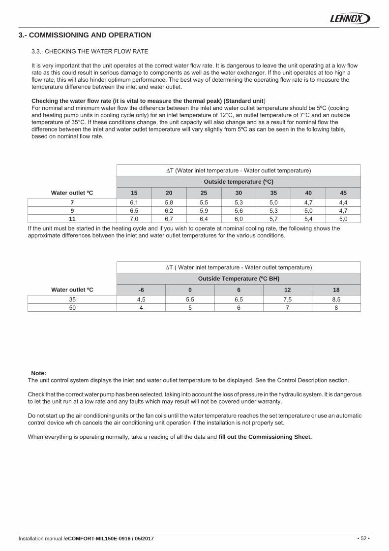
• 52 •
15 20 25 30 35 40 457 6,1 5,8 5,5 5,3 5,0 4,7 4,49 6,5 6,2 5,9 5,6 5,3 5,0 4,711 7,0 6,7 6,4 6,0 5,7 5,4 5,0
-6 0 6 12 1835 4,5 5,5 6,5 7,5 8,550 4 5 6 7 8
Installation manual /eCOMFORT-MIL150E-0916 / 05/2017
3.3.- CHECKING THE WATER FLOW RATE
It is very important that the unit operates at the correct water fl ow rate. It is dangerous to leave the unit operating at a low fl ow rate as this could result in serious damage to components as well as the water exchanger. If the unit operates at too high a fl ow rate, this will also hinder optimum performance. The best way of determining the operating fl ow rate is to measure the temperature difference between the inlet and water outlet.
Checking the water fl ow rate (it is vital to measure the thermal peak) (Standard unit)For nominal and minimum water fl ow the difference between the inlet and water outlet temperature should be 5ºC (cooling and heating pump units in cooling cycle only) for an inlet temperature of 12°C, an outlet temperature of 7°C and an outside temperature of 35°C. If these conditions change, the unit capacity will also change and as a result for nominal fl ow the difference between the inlet and water outlet temperature will vary slightly from 5ºC as can be seen in the following table, based on nominal fl ow rate.
∆T (Water inlet temperature - Water outlet temperature)
Outside temperature (ºC)
Water outlet ºC
If the unit must be started in the heating cycle and if you wish to operate at nominal cooling rate, the following shows the approximate differences between the inlet and water outlet temperatures for the various conditions.
∆T ( Water inlet temperature - Water outlet temperature)
Outside Temperature (ºC BH)
Water outlet ºC
Note: The unit control system displays the inlet and water outlet temperature to be displayed. See the Control Description section.
Check that the correct water pump has been selected, taking into account the loss of pressure in the hydraulic system. It is dangerous to let the unit run at a low rate and any faults which may result will not be covered under warranty.
Do not start up the air conditioning units or the fan coils until the water temperature reaches the set temperature or use an automatic control device which cancels the air conditioning unit operation if the installation is not properly set.
When everything is operating normally, take a reading of all the data and fi ll out the Commissioning Sheet.
3.- COMMISSIONING AND OPERATION
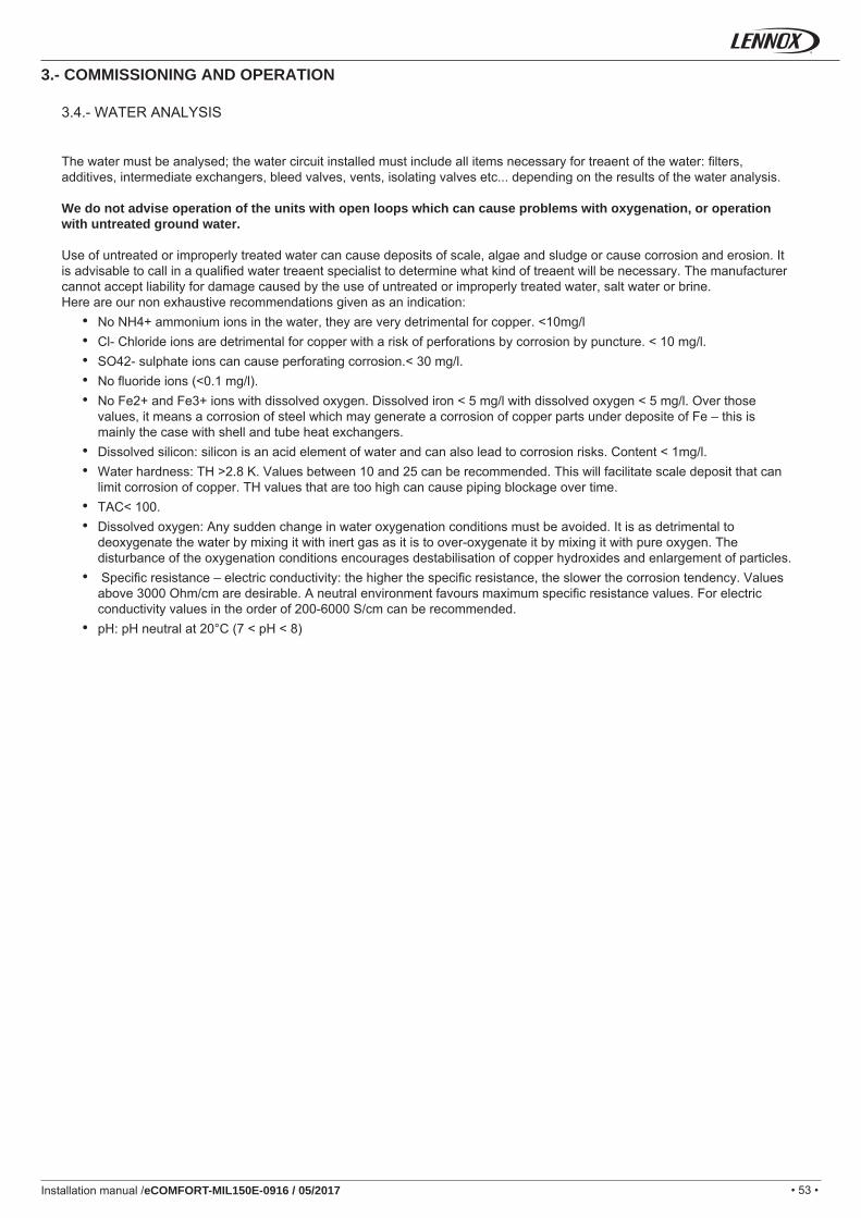
• 53 •Installation manual /eCOMFORT-MIL150E-0916 / 05/2017
3.4.- WATER ANALYSIS
The water must be analysed; the water circuit installed must include all items necessary for treaent of the water: fi lters, additives, intermediate exchangers, bleed valves, vents, isolating valves etc... depending on the results of the water analysis.
We do not advise operation of the units with open loops which can cause problems with oxygenation, or operation with untreated ground water.
Use of untreated or improperly treated water can cause deposits of scale, algae and sludge or cause corrosion and erosion. It is advisable to call in a qualifi ed water treaent specialist to determine what kind of treaent will be necessary. The manufacturer cannot accept liability for damage caused by the use of untreated or improperly treated water, salt water or brine.Here are our non exhaustive recommendations given as an indication:
• No NH4+ ammonium ions in the water, they are very detrimental for copper. <10mg/l• Cl- Chloride ions are detrimental for copper with a risk of perforations by corrosion by puncture. < 10 mg/l.• SO42- sulphate ions can cause perforating corrosion.< 30 mg/l.• No fl uoride ions (<0.1 mg/l).• No Fe2+ and Fe3+ ions with dissolved oxygen. Dissolved iron < 5 mg/l with dissolved oxygen < 5 mg/l. Over those
values, it means a corrosion of steel which may generate a corrosion of copper parts under deposite of Fe – this is mainly the case with shell and tube heat exchangers.
• Dissolved silicon: silicon is an acid element of water and can also lead to corrosion risks. Content < 1mg/l.• Water hardness: TH >2.8 K. Values between 10 and 25 can be recommended. This will facilitate scale deposit that can
limit corrosion of copper. TH values that are too high can cause piping blockage over time.• TAC< 100.• Dissolved oxygen: Any sudden change in water oxygenation conditions must be avoided. It is as detrimental to
deoxygenate the water by mixing it with inert gas as it is to over-oxygenate it by mixing it with pure oxygen. The disturbance of the oxygenation conditions encourages destabilisation of copper hydroxides and enlargement of particles.
• Specifi c resistance – electric conductivity: the higher the specifi c resistance, the slower the corrosion tendency. Values above 3000 Ohm/cm are desirable. A neutral environment favours maximum specifi c resistance values. For electric conductivity values in the order of 200-6000 S/cm can be recommended.
• pH: pH neutral at 20°C (7 < pH < 8)
3.- COMMISSIONING AND OPERATION
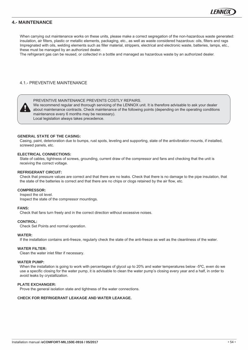
• 54 •Installation manual /eCOMFORT-MIL150E-0916 / 05/2017
4.1.- PREVENTIVE MAINTENANCE
4.- MAINTENANCE
PREVENTIVE MAINTENANCE PREVENTS COSTLY REPAIRS.We recommend regular and thorough servicing of the LENNOX unit. It is therefore advisable to ask your dealer about maintenance contracts. Check maintenance of the following points (depending on the operating conditions maintenance every 6 months may be necessary).Local legislation always takes precedence.
GENERAL STATE OF THE CASING:Casing, paint, deterioration due to bumps, rust spots, leveling and supporting, state of the antivibration mounts, if installed, screwed panels, etc.
ELECTRICAL CONNECTIONS:State of cables, tightness of screws, grounding, current draw of the compressor and fans and checking that the unit is receiving the correct voltage.
REFRIGERANT CIRCUIT:Check that pressure values are correct and that there are no leaks. Check that there is no damage to the pipe insulation, that the state of the batteries is correct and that there are no chips or clogs retained by the air fl ow, etc.
COMPRESSOR:Inspect the oil level.Inspect the state of the compressor mountings.
FANS:Check that fans turn freely and in the correct direction without excessive noises.
CONTROL:Check Set Points and normal operation.
WATER:If the installation contains anti-freeze, regularly check the state of the anti-freeze as well as the cleanliness of the water.
WATER FILTER:Clean the water inlet fi lter if necessary.
WATER PUMP:When the installation is going to work with percentages of glycol up to 20% and water temperatures below -5ºC, even do we use a specifi c closing for the water pump, it is advisable to clean the water pump’s closing every year and a half, in order to avoid leaks by crystallization.
PLATE EXCHANGER:Prove the general isolation state and tightness of the water connections.
CHECK FOR REFRIGERANT LEAKAGE AND WATER LEAKAGE.
When carrying out maintenance works on these units, please make a correct segregation of the non-hazardous waste generated: insulation, air fi lters, plastic or metallic elements, packaging, etc., as well as waste considered hazardous: oils, fi lters and rags Impregnated with oils, welding elements such as fi ller material, strippers, electrical and electronic waste, batteries, lamps, etc., these must be managed by an authorized dealer.The refrigerant gas can be reused, or collected in a bottle and managed as hazardous waste by an authorized dealer.
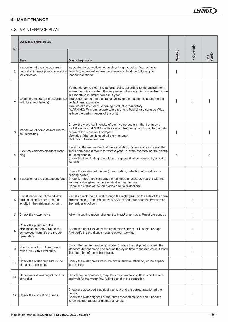
• 55 •
1 |
2 | | |
3 | | |
4 • • •
5 |
6 |
7 |
8 |
9 |
10 •
11 |
12 |
Installation manual /eCOMFORT-MIL150E-0916 / 05/2017
N°
MAINTENANCE PLAN
Mon
thly
+ Q
uart
erly
Hal
f Ye
arly
Task Operating mode
Inspection of the microchannel coils aluminum-copper connexions for corrosion
Inspection to be realised when cleaninng the coils. If corrosion is detected, a preventive treatment needs to be done following our recommendations
Cleanning the coils (In accordance with local regulations)
It’s mandatory to clean the external coils, according to the environment where the unit is located, the frequency of the cleanning varies from once in a month to minimum twice in a year.The performance and the sustainability of the machine is based on the perfect heat exchange.The use of a neutral pH cleaning product is mandatory(WARNING: Fins and copper tubes are very fragile! Any damage WILL reduce the performances of the unit).
Inspection of compressors electri-cal intensities
Check the electrical intensity of each compressor on the 3 phases of partial load and at 100% - with a certain frequency, according to the utili-zation of the machine. Example :Monthly : If the unit is used all over the yearHalf Year : if seasonal use
Electrcal cabinets air-fi lters clean-ning
Based on the environment of the installation, it’s mandatory to clean the fi lters from once a month to twice a year. To avoid overheating the electri-cal components.Check the fi lter fouling rate, clean or replace it when needed by an origi-nal fi lter
Inspection of the condensors fans
Check the rotation of the fan ( free rotation, detection of vibrations or bearing noises) Check for the Amps consumed on all three phases; compare it with the nominal value given in the electrical wiring diagram.Check the status of the fan blades and its protections.
Visual inspection of the oil level and check the oil for traces of acidity in the refrigerant circuits
Visually check the oil level through the sight glass on the side of the com-pressor casing. Test the oil every 3 years and after each intervention on the refrigerant circuit
Check the 4-way valve When in cooling mode, change it to HeatPump mode. Reset the control.
Check the position of the crankcase heaters (around the compressor) and it’s the proper opearation
Check the right fi xation of the crankcase heaters , if it is tight enough And verify the crankcase heaters overall working.
Verifi cation of the defrost cycle with 4-way valve inversion.
Switch the unit to heat pump mode. Change the set point to obtain the standard defrost mode and reduce the cycle time to the min value. Check the operation of the defrost cycle.
Check the water pressure in the circuit if it’s possible
Check the water pressure in the circuit and the effi ciency of the expan-sion velssel
Check overall working of the fl ow controller
Cut-off the compressors, stop the water circulation. Then start the unit and wait for the water fl ow failing signal in the controller.
Check the circulation pumps
Check the absorbed electrical intensity and the correct rotation of the pumps.Check the waterthigness of the pump mechanical seal and if needed follow the manufacturer maintanance plan.
4.- MAINTENANCE
4.2.- MAINTENANCE PLAN
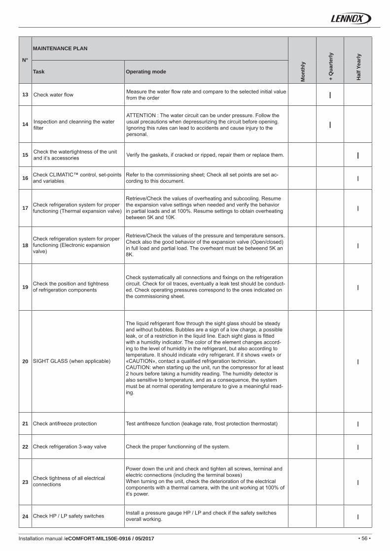
• 56 •
13 |
14 |
15 |
16 |
17 |
18 |
19 |
20 |
21 |
22 |
23 |
24 |
Installation manual /eCOMFORT-MIL150E-0916 / 05/2017
N°
MAINTENANCE PLAN
Mon
thly
+ Q
uart
erly
Hal
f Yea
rly
Task Operating mode
Check water fl ow Measure the water fl ow rate and compare to the selected initial value from the order
Inspection and cleanning the water fi lter
ATTENTION : The water circuit can be under pressure. Follow the usual precautions when depressurizing the circuit before opening. Ignoring this rules can lead to accidents and cause injury to the personal.
Check the watertightness of the unit and it’s accessories Verify the gaskets, if cracked or ripped, repair them or replace them.
Check CLIMATIC™ control, set-points and variables
Refer to the commissioning sheet; Check all set points are set ac-cording to this document.
Check refrigeration system for proper functioning (Thermal expansion valve)
Retrieve/Check the values of overheating and subcooling. Resume the expansion valve settings when needed and verify the behavior in partial loads and at 100%. Resume settings to obtain overheating between 5K and 10K
Check refrigeration system for proper functioning (Electronic expansion valve)
Retrieve/Check the values of the pressure and temperature sensors. Check also the good behavior of the expansion valve (Open/closed) in full load and partial load. The overheant must be betweend 5K an 8K.
Check the position and tightnessof refrigeration components
Check systematically all connections and fi xings on the refrigeration circuit. Check for oil traces, eventually a leak test should be conduct-ed. Check operating pressures correspond to the ones indicated on the commissioning sheet.
SIGHT GLASS (when applicable)
The liquid refrigerant fl ow through the sight glass should be steady and without bubbles. Bubbles are a sign of a low charge, a possible leak, or of a restriction in the liquid line. Each sight glass is fi tted with a humidity indicator. The color of the element changes accord-ing to the level of humidity in the refrigerant, but also according to temperature. It should indicate «dry refrigerant. If it shows «wet» or «CAUTION», contact a qualifi ed refrigeration technician.CAUTION: when starting up the unit, run the compressor for at least 2 hours before taking a humidity reading. The humidity detector is also sensitive to temperature, and as a consequence, the system must be at normal operating temperature to give a meaningful read-ing.
Check antifreeze protection Test antifreeze function (leakage rate, frost protection thermostat)
Check refrigeration 3-way valve Check the proper functionning of the system.
Check tightness of all electrical connections
Power down the unit and check and tighten all screws, terminal and electric connections (including the terminal boxes)When turning on the unit, check the deterioration of the electrical components with a thermal camera, with the unit working at 100% of it’s power.
Check HP / LP safety switches Install a pressure gauge HP / LP and check if the safety switches overall working.
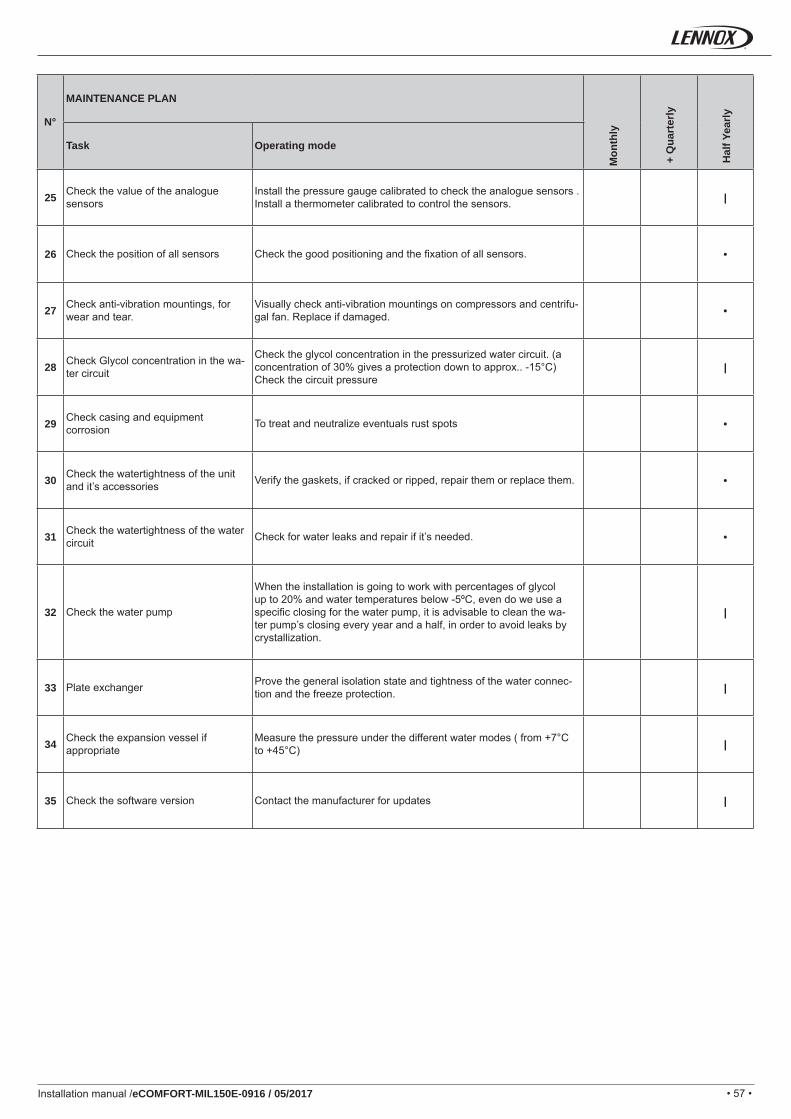
• 57 •
25 |
26 •
27 •
28 |
29 •
30 •
31 •
32 |
33 |
34 |
35 |
Installation manual /eCOMFORT-MIL150E-0916 / 05/2017
N°
MAINTENANCE PLAN
Mon
thly
+ Q
uart
erly
Hal
f Yea
rly
Task Operating mode
Check the value of the analogue sensors
Install the pressure gauge calibrated to check the analogue sensors .Install a thermometer calibrated to control the sensors.
Check the position of all sensors Check the good positioning and the fi xation of all sensors.
Check anti-vibration mountings, for wear and tear.
Visually check anti-vibration mountings on compressors and centrifu-gal fan. Replace if damaged.
Check Glycol concentration in the wa-ter circuit
Check the glycol concentration in the pressurized water circuit. (a concentration of 30% gives a protection down to approx.. -15°C)Check the circuit pressure
Check casing and equipment corrosion To treat and neutralize eventuals rust spots
Check the watertightness of the unit and it’s accessories Verify the gaskets, if cracked or ripped, repair them or replace them.
Check the watertightness of the water circuit Check for water leaks and repair if it’s needed.
Check the water pump
When the installation is going to work with percentages of glycol up to 20% and water temperatures below -5ºC, even do we use a specifi c closing for the water pump, it is advisable to clean the wa-ter pump’s closing every year and a half, in order to avoid leaks by crystallization.
Plate exchanger Prove the general isolation state and tightness of the water connec-tion and the freeze protection.
Check the expansion vessel if appropriate
Measure the pressure under the different water modes ( from +7°C to +45°C)
Check the software version Contact the manufacturer for updates
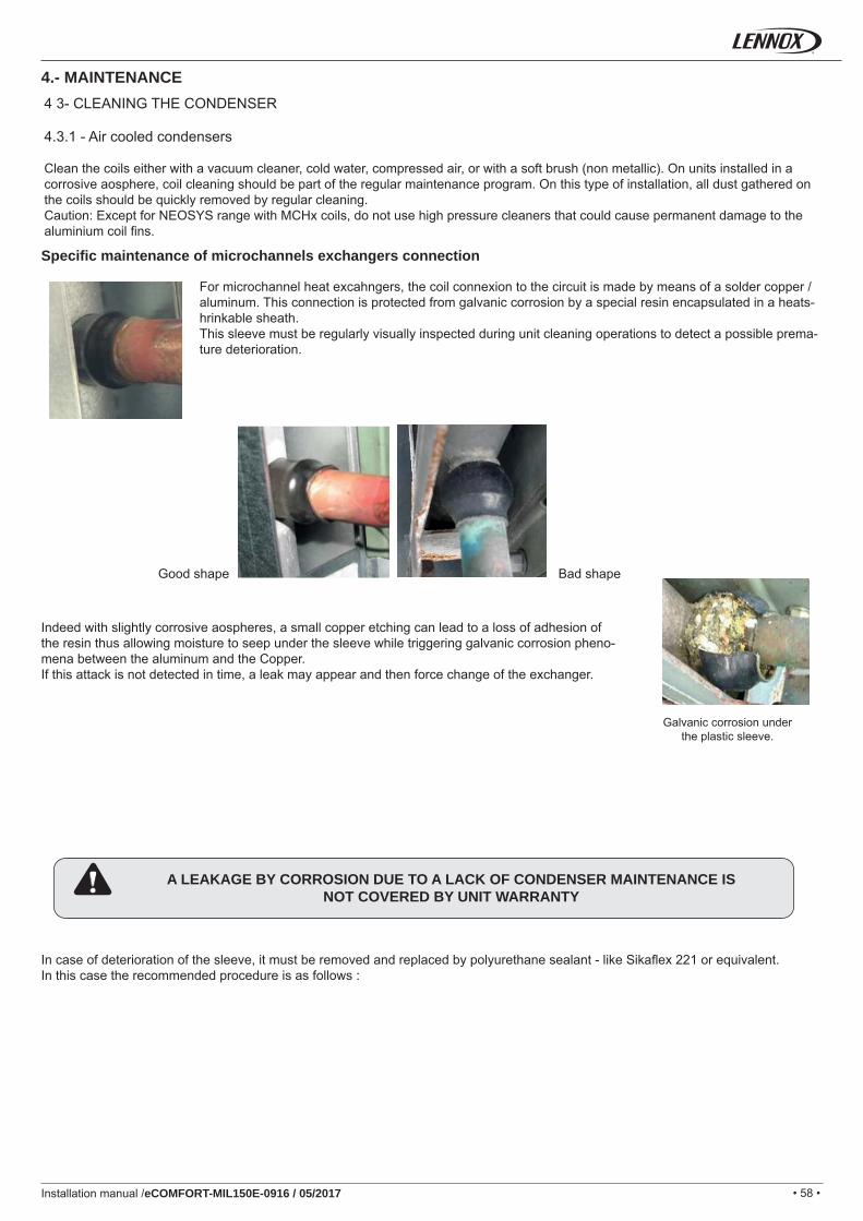
• 58 •Installation manual /eCOMFORT-MIL150E-0916 / 05/2017
4 3- CLEANING THE CONDENSER
4.3.1 - Air cooled condensers
Clean the coils either with a vacuum cleaner, cold water, compressed air, or with a soft brush (non metallic). On units installed in a corrosive aosphere, coil cleaning should be part of the regular maintenance program. On this type of installation, all dust gathered on the coils should be quickly removed by regular cleaning.Caution: Except for NEOSYS range with MCHx coils, do not use high pressure cleaners that could cause permanent damage to the aluminium coil fi ns.
For microchannel heat excahngers, the coil connexion to the circuit is made by means of a solder copper / aluminum. This connection is protected from galvanic corrosion by a special resin encapsulated in a heats-hrinkable sheath.This sleeve must be regularly visually inspected during unit cleaning operations to detect a possible prema-ture deterioration.
Specifi c maintenance of microchannels exchangers connection
Bad shapeGood shape
Indeed with slightly corrosive aospheres, a small copper etching can lead to a loss of adhesion of the resin thus allowing moisture to seep under the sleeve while triggering galvanic corrosion pheno-mena between the aluminum and the Copper.If this attack is not detected in time, a leak may appear and then force change of the exchanger.
Galvanic corrosion underthe plastic sleeve.
A LEAKAGE BY CORROSION DUE TO A LACK OF CONDENSER MAINTENANCE ISNOT COVERED BY UNIT WARRANTY
In case of deterioration of the sleeve, it must be removed and replaced by polyurethane sealant - like Sikafl ex 221 or equivalent.In this case the recommended procedure is as follows :
4.- MAINTENANCE
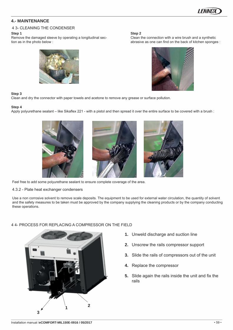
• 59 •
1 23
Installation manual /eCOMFORT-MIL150E-0916 / 05/2017
Step 1Remove the damaged sleeve by operating a longitudinal sec-tion as in the photo below :
Step 2Clean the connection with a wire brush and a synthetic abrasive as one can fi nd on the back of kitchen sponges :
Step 3Clean and dry the connector with paper towels and acetone to remove any grease or surface pollution.
Step 4Apply polyurethane sealant – like Sikafl ex 221 - with a pistol and then spread it over the entire surface to be covered with a brush :
Feel free to add some polyurethane sealant to ensure complete coverage of the area.
4.3.2 - Plate heat exchanger condensers
Use a non corrosive solvent to remove scale deposits. The equipment to be used for external water circulation, the quantity of solventand the safety measures to be taken must be approved by the company supplying the cleaning products or by the company conductingthese operations.
4 4- PROCESS FOR REPLACING A COMPRESSOR ON THE FIELD
1. Unweld discharge and suction line
2. Unscrew the rails compressor support
3. Slide the rails of compressors out of the unit
4. Replace the compressor
5. Slide again the rails inside the unit and fi x the rails
4 3- CLEANING THE CONDENSER
4.- MAINTENANCE
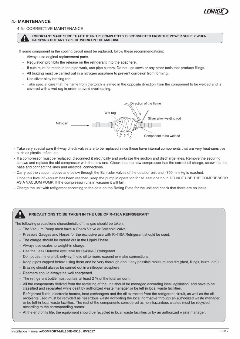
• 60 •Installation manual /eCOMFORT-MIL150E-0916 / 05/2017
4.5.- CORRECTIVE MAINTENANCE
IIMPORTANT MAKE SURE THAT THE UNIT IS COMPLETELY DISCONNECTED FROM THE POWER SUPPLY WHEN CARRYING OUT ANY TYPE OF WORK ON THE MACHINE
If some component in the cooling circuit must be replaced, follow these recommendations:- Always use original replacement parts.- Regulation prohibits the release on the refrigerant into the aosphere.- If cuts must be made in the pipe work, use pipe cutters. Do not use saws or any other tools that produce fi lings.- All brazing must be carried out in a nitrogen aosphere to prevent corrosion from forming.- Use silver alloy brazing rod.- Take special care that the fl ame from the torch is aimed in the opposite direction from the component to be welded and is
covered with a wet rag in order to avoid overheating.
Component to be welded
Nitrógen
Wet rag
Direction of the fl ame
Silver alloy welding rod
- Take very special care if 4-way check valves are to be replaced since these have internal components that are very heat-sensitive such as plastic, tefl on, etc.
- If a compressor must be replaced, disconnect it electrically and un-braze the suction and discharge lines. Remove the securing screws and replace the old compressor with the new one. Check that the new compressor has the correct oil charge, screw it to the base and connect the lines and electrical connections.
- Carry out the vacuum above and below through the Schrader valves of the outdoor unit until -750 mm Hg is reached. Once this level of vacuum has been reached, keep the pump in operation for at least one hour. DO NOT USE THE COMPRESSOR
AS A VACUUM PUMP. If the compressor runs in vacuum it will fail.- Charge the unit with refrigerant according to the data on the Rating Plate for the unit and check that there are no leaks.
PRECAUTIONS TO BE TAKEN IN THE USE OF R-410A REFRIGERANT
The following precautions characteristic of this gas should be taken:- The Vacuum Pump must have a Check Valve or Solenoid Valve.- Pressure Gauges and Hoses for the exclusive use with R-410A Refrigerant should be used.- The charge should be carried out in the Liquid Phase.- Always use scales to weight-in charge- Use the Leak Detector exclusive for R-410AC Refrigerant. - Do not use mineral oil, only synthetic oil to ream, expand or make connections.- Keep pipes capped before using them and be very thorough about any possible moisture and dirt (dust, fi lings, burrs, etc.).- Brazing should always be carried out in a nitrogen aosphere.- Reamers should always be well sharpened.- The refrigerant bottle must contain at least 2 % of the total amount.- All the components derived from the recycling of the unit should be managed according local legislation, and have to be
classifi ed and separated while dealt by authorized waste manager or be left in local waste facilities.- Refrigerant fl uids, electronic boards, heat exchangers and the oil extracted from the refrigerant circuit, as well as the oil
recipients used must be recycled as hazardous waste according the local normative through an authorized waste manager or be left in local waste facilities. The rest of the components considered as non-hazardous wastes must be recycled according to the corresponding norms.
- At the end of its life, the equipment should be recycled in local waste facilities or by an authorized waste manager.
4.- MAINTENANCE
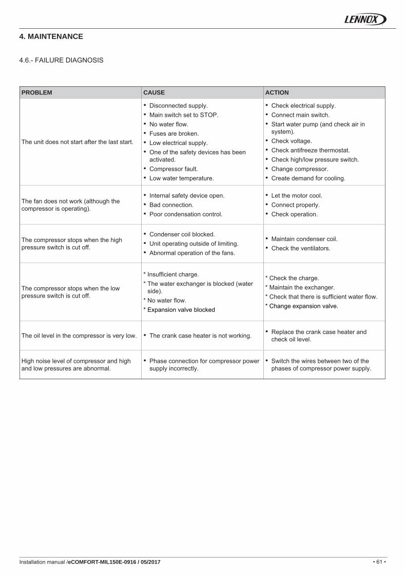
• 61 •Installation manual /eCOMFORT-MIL150E-0916 / 05/2017
4.6.- FAILURE DIAGNOSIS
PROBLEM CAUSE ACTION
The unit does not start after the last start.
• Disconnected supply.• Main switch set to STOP.• No water fl ow.• Fuses are broken.• Low electrical supply.• One of the safety devices has been
activated.• Compressor fault.• Low water temperature.
• Check electrical supply.• Connect main switch.• Start water pump (and check air in
system).• Check voltage.• Check antifreeze thermostat.• Check high/low pressure switch.• Change compressor.• Create demand for cooling.
The fan does not work (although the compressor is operating).
• Internal safety device open.• Bad connection.• Poor condensation control.
• Let the motor cool.• Connect properly.• Check operation.
The compressor stops when the high pressure switch is cut off.
• Condenser coil blocked.• Unit operating outside of limiting.• Abnormal operation of the fans.
• Maintain condenser coil.• Check the ventilators.
The compressor stops when the low pressure switch is cut off.
* Insuffi cient charge.* The water exchanger is blocked (water
side).* No water fl ow.* Expansion valve blocked
* Check the charge.* Maintain the exchanger.* Check that there is suffi cient water fl ow.* Change expansion valve.
The oil level in the compressor is very low. • The crank case heater is not working. • Replace the crank case heater and check oil level.
High noise level of compressor and high and low pressures are abnormal.
• Phase connection for compressor power supply incorrectly.
• Switch the wires between two of the phases of compressor power supply.
4. MAINTENANCE
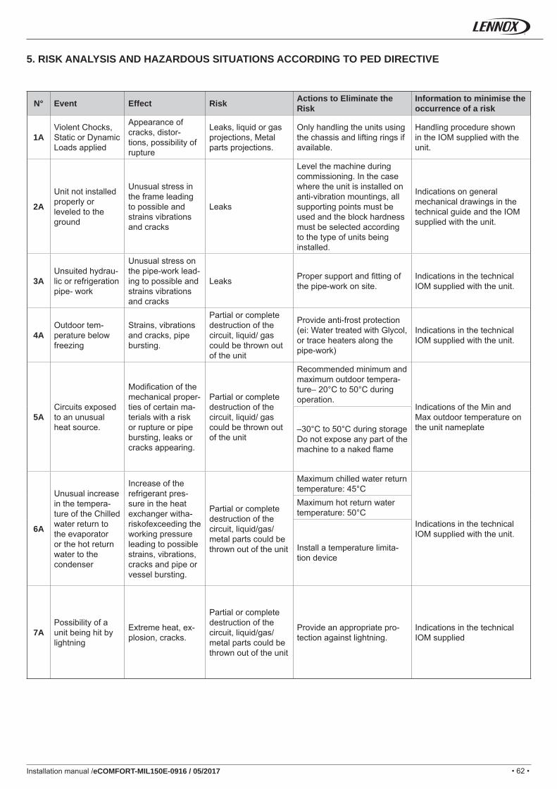
• 62 •Installation manual /eCOMFORT-MIL150E-0916 / 05/2017
5. RISK ANALYSIS AND HAZARDOUS SITUATIONS ACCORDING TO PED DIRECTIVE
N° Event Effect Risk Actions to Eliminate the Risk
Information to minimise the occurrence of a risk
1AViolent Chocks, Static or Dynamic Loads applied
Appearance of cracks, distor-tions, possibility of rupture
Leaks, liquid or gas projections, Metal parts projections.
Only handling the units using the chassis and lifting rings if available.
Handling procedure shown in the IOM supplied with the unit.
2A
Unit not installed properly or leveled to the ground
Unusual stress in the frame leading to possible and strains vibrations and cracks
Leaks
Level the machine during commissioning. In the case where the unit is installed on anti-vibration mountings, all supporting points must be used and the block hardness must be selected according to the type of units being installed.
Indications on general mechanical drawings in the technical guide and the IOM supplied with the unit.
3AUnsuited hydrau-lic or refrigeration pipe- work
Unusual stress on the pipe-work lead-ing to possible and strains vibrations and cracks
Leaks Proper support and fi tting of the pipe-work on site.
Indications in the technical IOM supplied with the unit.
4AOutdoor tem-perature below freezing
Strains, vibrations and cracks, pipe bursting.
Partial or complete destruction of the circuit, liquid/ gas could be thrown out of the unit
Provide anti-frost protection (ei: Water treated with Glycol, or trace heaters along the pipe-work)
Indications in the technical IOM supplied with the unit.
5ACircuits exposed to an unusual heat source.
Modifi cation of the mechanical proper-ties of certain ma-terials with a risk or rupture or pipe bursting, leaks or cracks appearing.
Partial or complete destruction of the circuit, liquid/ gas could be thrown out of the unit
Recommended minimum and maximum outdoor tempera-ture– 20°C to 50°C during operation.
Indications of the Min and Max outdoor temperature on the unit nameplate–30°C to 50°C during storage
Do not expose any part of the machine to a naked fl ame
6A
Unusual increase in the tempera-ture of the Chilled water return to the evaporator or the hot return water to the condenser
Increase of the refrigerant pres-sure in the heat exchanger witha-riskofexceeding the working pressure leading to possible strains, vibrations, cracks and pipe or vessel bursting.
Partial or complete destruction of the circuit, liquid/gas/ metal parts could be thrown out of the unit
Maximum chilled water return temperature: 45°C
Indications in the technical IOM supplied with the unit.
Maximum hot return water temperature: 50°C
Install a temperature limita-tion device
7APossibility of a unit being hit by lightning
Extreme heat, ex-plosion, cracks.
Partial or complete destruction of the circuit, liquid/gas/ metal parts could be thrown out of the unit
Provide an appropriate pro-tection against lightning.
Indications in the technical IOM supplied
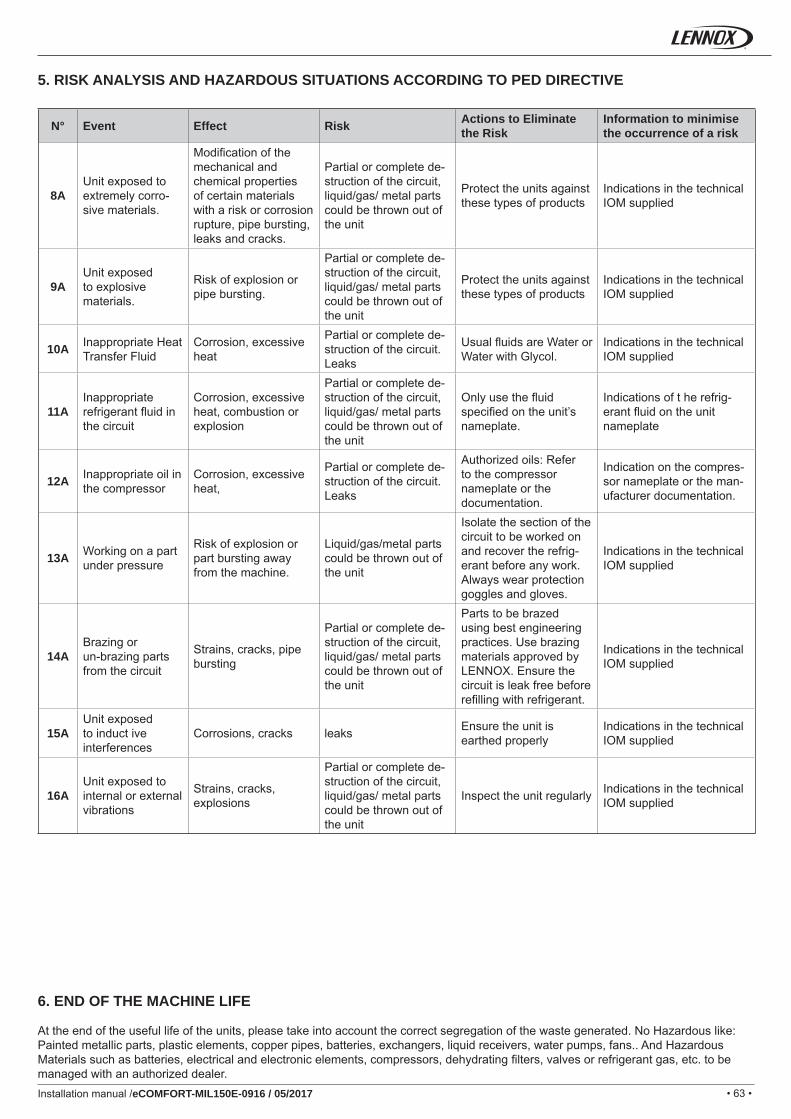
• 63 •Installation manual /eCOMFORT-MIL150E-0916 / 05/2017
5. RISK ANALYSIS AND HAZARDOUS SITUATIONS ACCORDING TO PED DIRECTIVE
N° Event Effect Risk Actions to Eliminate the Risk
Information to minimise the occurrence of a risk
8AUnit exposed to extremely corro-sive materials.
Modifi cation of the mechanical and chemical properties of certain materials with a risk or corrosion rupture, pipe bursting, leaks and cracks.
Partial or complete de-struction of the circuit, liquid/gas/ metal parts could be thrown out of the unit
Protect the units against these types of products
Indications in the technical IOM supplied
9AUnit exposed to explosive materials.
Risk of explosion or pipe bursting.
Partial or complete de-struction of the circuit, liquid/gas/ metal parts could be thrown out of the unit
Protect the units against these types of products
Indications in the technical IOM supplied
10A Inappropriate Heat Transfer Fluid
Corrosion, excessive heat
Partial or complete de-struction of the circuit. Leaks
Usual fl uids are Water or Water with Glycol.
Indications in the technical IOM supplied
11AInappropriate refrigerant fl uid in the circuit
Corrosion, excessive heat, combustion or explosion
Partial or complete de-struction of the circuit, liquid/gas/ metal parts could be thrown out of the unit
Only use the fl uid specifi ed on the unit’s nameplate.
Indications of t he refrig-erant fl uid on the unit nameplate
12A Inappropriate oil in the compressor
Corrosion, excessive heat,
Partial or complete de-struction of the circuit. Leaks
Authorized oils: Refer to the compressor nameplate or the documentation.
Indication on the compres-sor nameplate or the man-ufacturer documentation.
13A Working on a part under pressure
Risk of explosion or part bursting away from the machine.
Liquid/gas/metal parts could be thrown out of the unit
Isolate the section of the circuit to be worked on and recover the refrig-erant before any work. Always wear protection goggles and gloves.
Indications in the technical IOM supplied
14ABrazing or un-brazing parts from the circuit
Strains, cracks, pipe bursting
Partial or complete de-struction of the circuit, liquid/gas/ metal parts could be thrown out of the unit
Parts to be brazed using best engineering practices. Use brazing materials approved by LENNOX. Ensure the circuit is leak free before refi lling with refrigerant.
Indications in the technical IOM supplied
15AUnit exposed to induct ive interferences
Corrosions, cracks leaks Ensure the unit is earthed properly
Indications in the technical IOM supplied
16AUnit exposed to internal or external vibrations
Strains, cracks, explosions
Partial or complete de-struction of the circuit, liquid/gas/ metal parts could be thrown out of the unit
Inspect the unit regularly Indications in the technical IOM supplied
6. END OF THE MACHINE LIFE
At the end of the useful life of the units, please take into account the correct segregation of the waste generated. No Hazardous like: Painted metallic parts, plastic elements, copper pipes, batteries, exchangers, liquid receivers, water pumps, fans.. And Hazardous Materials such as batteries, electrical and electronic elements, compressors, dehydrating fi lters, valves or refrigerant gas, etc. to be managed with an authorized dealer.
• 64 •Installation manual /eCOMFORT-MIL150E-0916 / 05/2017
NOTES

+ 32 3 633 3045 +351 229 066 050
+33 1 64 76 23 23 +7 495 626 56 53
+49 (0) 211 950 79 600 +34 915 401 810
+ 39 02 495 26 200 +38 044 585 59 10
+ 31 332 471 800 +44 1604 669 100
+48 22 58 48 610
LENNOX DISTRIBUTION
+33 4 72 23 20 20
+ 32 3 633 3045 +48 22 58 48 610
+33 1 64 76 23 23 +351 229 066 050
+49 (0) 211 950 79 60 +34 915 401 810
+ 39 02 495 26 200 +38 044 585 59 10
+ 31 332 471 800 +44 1604 669 100
LENNOX DISTRIBUTION
+33 4 72 23 20 20
www.lennoxemea.com
MIL150E-0916 05-2017
Due to LENNOX EMEA ongoing commitment to quality, the specifi cations, ratings and dimensions are subject to change without notice and without incurring liability.Improper installation, adjustment, alteration, service or maintenance can cause property damage or personal injury.Installation and service must be performed by a qualifi ed installer and servicing agency.
SALES OFFICES :
BELGIUM AND LUXEMBOURG POLAND
FRANCE PORTUGAL
GERMANY SPAIN
ITALY UKRAINE
NETHERLANDS UNITED KINGDOM AND IRELAND
OTHER COUNTRIES :