Embed Size (px)
Citation preview
PRO-DIA
LOG +
Quality Management
Systems
Air-Cooled Liquid Chillers/Air-to-Water Heat Pumps
30RB/RQ 017-033Nominal cooling capacity 17-33 kWNominal heating capacity 17-33 kW
The new generation of Aquasnap liquid chillers/heat pumps was designed for commercial applications such as the air conditioning of offices and hotels etc.
The new Aquasnap units integrate the latest technological innovations:
ozone-friendly refrigerant R410Ascroll compressorslow-noise fansauto-adaptive microprocessor control
The standard Aquasnap units are equipped with a hydronic module integrated into the unit chassis, limiting the installation to straightforward operations like connection of the power supply and the water supply and return piping.
----
Features
Quiet operationCompressors
Low-noise scroll compressors with low vibration levelsThe compressor assembly is installed on an independent chassis and supported by anti-vibration mountings
Air heat exchanger sectionVertical air heat exchanger coilsAnti-vibration protection grilles protect the heat exchanger against possible shocks.The latest-generation low-noise fans are now even quieter and do not generate intrusive low-frequency noiseRigid fan installation for reduced start-up noise
■
--
■
--
-
-
�
Easy and fast installationIntegrated hydronic module
High-pressure centrifugal water pump
Access panels, sizes 017-021
■
-
Economical operationIncreased energy efficiency at part load
The exceptionally high energy efficiency of the Aquasnap unit is the result of a long qualification and optimisation process. The whole range is rated class A in both cooling mode (EER) and heating mode (COP) - in accordance with the Eurovent certification programmes for air conditioning and heating/cooling floors (see table on page 4).
Reduced maintenance costsMaintenance-free scroll compressorsFast diagnosis of possible incidents and their history via the Pro-Dialog+ controlR410A refrigerant is easier to use than other refrigerant blends
Environmental careOzone-friendly R410A refrigerant
Chlorine-free refrigerant of the HFC group with zero ozone depletion potentialHigh-density refrigerant, therefore less refrigerant requiredVery efficient - gives an increased energy efficiency ratio (EER)
Leak-tight refrigerant circuitBrazed refrigerant connections for increased leak-tightnessVerification of pressure transducers and temperature sensors without transferring refrigerant charge
Hydronic module, sizes 026-033
■
-
■
--
-
■
-
-
-
■
-
-
Water filter protecting the water pump against circulating debrisHigh-capacity membrane expansion tank ensures pressurisation of the water circuitOverpressure valve, set to 4 barPressure gauge to measure the system pressure. Automatic purge valve positioned at the highest point of the hydronic module to remove air from the system.Thermal insulation and frost protection down to -10°C, using an electric resistance heater and pump cycling.Integrated water fill system to ensure correct water pressure (option/accessory)
Physical featuresWith its small footprint the unit blends in with any architectural styles.The unit is enclosed by easily removable panels, covering all components (except air heat exchanger and fans).
Simplified electrical connectionsA single power supply point (power supply without neutral available as an option)Main disconnect switch with high trip capacityTransformer for safe �4 V control circuit supply included
Fast commissioningSystematic factory operation test before shipmentQuick-test function for step-by-step verification of the instruments, electrical components and motors
-
-
---
-
-
■
-
-
■
-
--
■
--
Superior reliabilityState-of-the-art concept
Cooperation with specialist laboratories and use of limit simulation tools (finite element calculations) for the design of the critical components, e.g. motor supports, suction/discharge piping etc.
Auto-adaptive controlControl algorithm prevents excessive compressor cycling and permits reduction of the water quantity in the hydronic circuit (Carrier patent)
Exceptional endurance testsCorrosion resistance tests in salt mist in the laboratoryAccelerated ageing test on components that are submitted to continuous operation: compressor piping, fan supportsTransport simulation test in the laboratory on a vibrating table.
■
-
■
-
■
--
-
3
Interface access, sizes 026-033
Remote operating mode with volt-free contacts (standard)
A simple two-wire communication bus between the RS485 port of the Aquasnap and the Carrier Comfort Network offers multiple remote control, monitoring and diagnostic possibilities. Carrier offers a vast choice of control products, specially designed to control, manage and supervise the operation of an air conditioning system. Please consult your Carrier representative for more information on these products.
Start/stop: opening of this contact will shut down the unitDual set point: closing of this contact activates a second set point (example: unoccupied mode)Alert indication: this volt-free contact indicates the presence of a minor faultAlarm indication: this volt-free contact indicates the presence of a major fault that has led to the shut-down of the unitUser safety: this contact can be used for any customer safety loop, closing of the contact generates a specific alarmOut of service: this signal indicates that the unit is completely out of serviceUnit capacity: this analogue output (0-10 V) gives an immediate indication of the unit capacityCompressor operation: this contact signals that the compressor is in operation
Remote interface (accessory)This interface allows access to the same menus as the unit interface and can be installed up to 300 m away. It includes a box that can be mounted inside the building. The power supply is provided via a ��0 V/�4V transformer supplied.
-
-
-
-
-
-
-
-
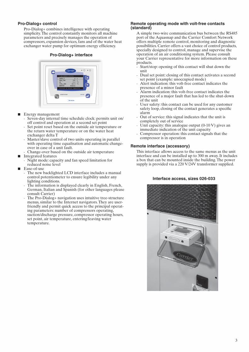
Pro-Dialog+ controlPro-Dialog+ combines intelligence with operating simplicity. The control constantly monitors all machine parameters and precisely manages the operation of compressors, expansion devices, fans and of the water heat exchanger water pump for optimum energy efficiency.
Pro-Dialog+ interface
\\MAINMENU\STATUS
Circuit B Total Capacity
CAPB_T 0 %DEM_LIM 100 %SP 4.2 °CCTRL_PNT -28.9 °CEMSTOP dsable
ENTERSTART/STOP
PRO-DIALOG+
Energy managementSeven-day internal time schedule clock: permits unit on/off control and operation at a second set pointSet point reset based on the outside air temperature or the return water temperature or on the water heat exchanger delta TMaster/slave control of two units operating in parallel with operating time equalisation and automatic change-over in case of a unit fault.Change-over based on the outside air temperature
Integrated featuresNight mode: capacity and fan speed limitation for reduced noise level
Ease-of-useThe new backlighted LCD interface includes a manual control potentiometer to ensure legibility under any lighting conditions.The information is displayed clearly in English, French, German, Italian and Spanish (for other languages please consult Carrier)The Pro-Dialog+ navigation uses intuitive tree-structure menus, similar to the Internet navigators. They are user-friendly and permit quick access to the principal operat-ing parameters: number of compressors operating, suction/discharge pressure, compressor operating hours, set point, air temperature, entering/leaving water temperature.
■
-
-
-
-■
-
■
-
-
-
4
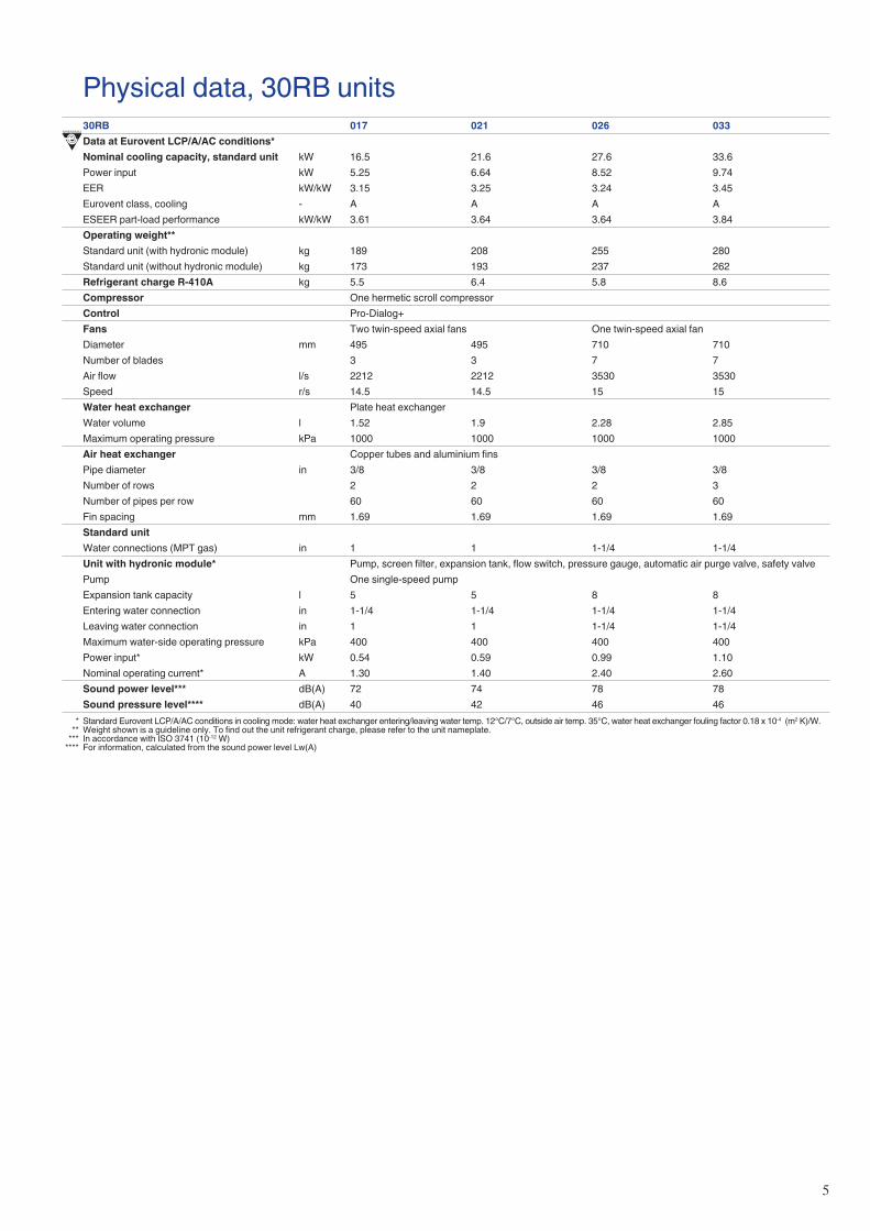
Eurovent qualification programmes30RB/RQ 017-033Programme Operating mode Operating conditions Class A criteria 30RB 30RQ
Outside air temperature, °C Water temperature, °CAir conditioning Cooling mode 35 12/7 3.1 X X
Heating mode 7/6 40/45 3.2 - XHeating/cooling floors Cooling mode 35 23/18 3.8 - X
Heating mode 7/6 30/35 4.05 - X X Unit class A - Not applicable
Options and accessoriesOptions Description Advantages UseUnit without hydronic module Unit without hydronic module The pump can be remote from the unit 30RB/RQ 017-033Integrated water fill system Designed for units with hydronic module Unit adds the water into the circuit 30RB/RQ 017-033Power supply without neutral The control box does not include the neutral connection
(400 V- 3 ph - 50 Hz)Used, if neutral is not required 30RB/RQ 017-033
Accessories Description Advantages UseJBus gateway Two-directional communications board, complies with
JBus protocolEasy connection by communication bus to a building management system
30RB/RQ 017-033
BacNet gateway Two-directional communications board, complies with BacNet protocol
Easy connection by communication bus to a building management system
30RB/RQ 017-033
LonTalk gateway Two-directional communications board, complies with LonTalk protocol
Easy connection by communication bus to a building management system
30RB/RQ 017-033
Remote interface Remotely installed user interface Remote unit control up to 300 m 30RB/RQ 017-033Integrated water fill system Designed for units with hydronic module Unit adds the water into the circuit 30RB/RQ 017-033
5
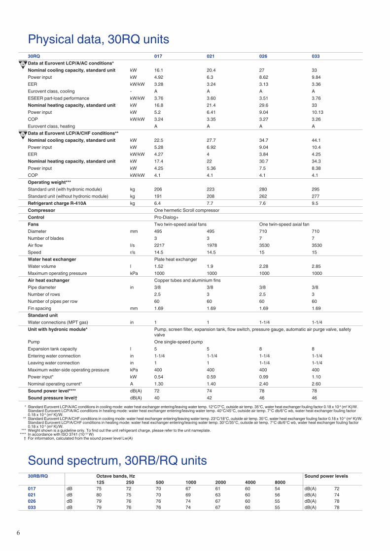
Physical data, 30RB units30RB 017 021 026 033Data at Eurovent LCP/A/AC conditions*Nominal cooling capacity, standard unit kW 16.5 21.6 27.6 33.6Power input kW 5.25 6.64 8.52 9.74EER kW/kW 3.15 3.25 3.24 3.45Eurovent class, cooling - A A A AESEER part-load performance kW/kW 3.61 3.64 3.64 3.84Operating weight**Standard unit (with hydronic module) kg 189 208 255 280Standard unit (without hydronic module) kg 173 193 237 262Refrigerant charge R-410A kg 5.5 6.4 5.8 8.6Compressor One hermetic scroll compressorControl Pro-Dialog+Fans Two twin-speed axial fans One twin-speed axial fanDiameter mm 495 495 710 710Number of blades 3 3 7 7Air flow l/s 2212 2212 3530 3530Speed r/s 14.5 14.5 15 15Water heat exchanger Plate heat exchangerWater volume l 1.52 1.9 2.28 2.85Maximum operating pressure kPa 1000 1000 1000 1000Air heat exchanger Copper tubes and aluminium finsPipe diameter in 3/8 3/8 3/8 3/8Number of rows 2 2 2 3Number of pipes per row 60 60 60 60Fin spacing mm 1.69 1.69 1.69 1.69Standard unitWater connections (MPT gas) in 1 1 1-1/4 1-1/4Unit with hydronic module* Pump, screen filter, expansion tank, flow switch, pressure gauge, automatic air purge valve, safety valvePump One single-speed pumpExpansion tank capacity l 5 5 8 8Entering water connection in 1-1/4 1-1/4 1-1/4 1-1/4Leaving water connection in 1 1 1-1/4 1-1/4Maximum water-side operating pressure kPa 400 400 400 400Power input* kW 0.54 0.59 0.99 1.10Nominal operating current* A 1.30 1.40 2.40 2.60Sound power level*** dB(A) 72 74 78 78Sound pressure level**** dB(A) 40 42 46 46
* Standard Eurovent LCP/A/AC conditions in cooling mode: water heat exchanger entering/leaving water temp. 12°C/7°C, outside air temp. 35°C, water heat exchanger fouling factor 0.18 x 10⁻⁴ (m2 K)/W. ** Weight shown is a guideline only. To find out the unit refrigerant charge, please refer to the unit nameplate. *** In accordance with ISO 3741 (10-12 W) **** For information, calculated from the sound power level Lw(A)
�
Physical data, 30RQ units30RQ 017 021 026 033Data at Eurovent LCP/A/AC conditions*Nominal cooling capacity, standard unit kW 16.1 20.4 27 33Power input kW 4.92 6.3 8.62 9.84EER kW/kW 3.28 3.24 3.13 3.36Eurovent class, cooling - A A A AESEER part-load performance kW/kW 3.76 3.60 3.51 3.76Nominal heating capacity, standard unit kW 16.8 21.4 29.6 33Power input kW 5.2 6.41 9.04 10.13COP kW/kW 3.24 3.35 3.27 3.26Eurovent class, heating A A A AData at Eurovent LCP/A/CHF conditions**Nominal cooling capacity, standard unit kW 22.5 27.7 34.7 44.1Power input kW 5.28 6.92 9.04 10.4EER kW/kW 4.27 4 3.84 4.25Nominal heating capacity, standard unit kW 17.4 22 30.7 34.3Power input kW 4.25 5.36 7.5 8.38COP kW/kW 4.1 4.1 4.1 4.1Operating weight***Standard unit (with hydronic module) kg 206 223 280 295Standard unit (without hydronic module) kg 191 208 262 277Refrigerant charge R-410A kg 6.4 7.7 7.6 9.5Compressor One hermetic Scroll compressorControl Pro-Dialog+Fans Two twin-speed axial fans One twin-speed axial fanDiameter mm 495 495 710 710Number of blades 3 3 7 7Air flow l/s 2217 1978 3530 3530Speed r/s 14.5 14.5 15 15Water heat exchanger Plate heat exchangerWater volume l 1.52 1.9 2.28 2.85Maximum operating pressure kPa 1000 1000 1000 1000Air heat exchanger Copper tubes and aluminium finsPipe diameter in 3/8 3/8 3/8 3/8Number of rows 2.5 3 2.5 3Number of pipes per row 60 60 60 60Fin spacing mm 1.69 1.69 1.69 1.69Standard unitWater connections (MPT gas) in 1 1 1-1/4 1-1/4Unit with hydronic module* Pump, screen filter, expansion tank, flow switch, pressure gauge, automatic air purge valve, safety
valvePump One single-speed pumpExpansion tank capacity l 5 5 8 8Entering water connection in 1-1/4 1-1/4 1-1/4 1-1/4Leaving water connection in 1 1 1-1/4 1-1/4Maximum water-side operating pressure kPa 400 400 400 400Power input* kW 0.54 0.59 0.99 1.10Nominal operating current* A 1.30 1.40 2.40 2.60Sound power level**** dB(A) 72 74 78 78Sound pressure level† dB(A) 40 42 46 46
* Standard Eurovent LCP/A/AC conditions in cooling mode: water heat exchanger entering/leaving water temp. 12°C/7°C, outside air temp. 35°C, water heat exchanger fouling factor 0.18 x 10⁻⁴ (m2 K)/W. Standard Eurovent LCP/A/AC conditions in heating mode: water heat exchanger entering/leaving water temp. 40°C/45°C, outside air temp. 7°C db/6°C wb, water heat exchanger fouling factor
0.18 x 10⁻⁴ (m2 K)/W. ** Standard Eurovent LCP/A/CHF conditions in cooling mode: water heat exchanger entering/leaving water temp. 23°C/18°C, outside air temp. 35°C, water heat exchanger fouling factor 0.18 x 10⁻⁴ (m2 K)/W. Standard Eurovent LCP/A/CHF conditions in heating mode: water heat exchanger entering/leaving water temp. 30°C/35°C, outside air temp. 7°C db/6°C wb, water heat exchanger fouling factor
0.18 x 10⁻⁴ (m2 K)/W. *** Weight shown is a guideline only. To find out the unit refrigerant charge, please refer to the unit nameplate. **** In accordance with ISO 3741 (10-12 W) † For information, calculated from the sound power level Lw(A)
Sound spectrum, 30RB/RQ units30RB/RQ Octave bands, Hz Sound power levels
125 250 500 1000 2000 4000 8000017 dB 75 72 70 67 61 60 54 dB(A) 72021 dB 80 75 70 69 63 60 56 dB(A) 74026 dB 79 76 76 74 67 60 55 dB(A) 78033 dB 79 76 76 74 67 60 55 dB(A) 78
7
Electrical data, 30RB/RQ units30RB/RQ 017 021 026 033Power circuitNominal power supply V-ph-Hz 400-3-50Voltage range V 340-440Control circuit supply 24 V via internal transformerMaximum start-up current (Un)* A 75 95 118 118Unit power factor at nominal capacity** 0.84 0.79 0.77 0.81Maximum operating power input** kW 7.8 9.1 11 13.8Nominal unit operating current draw*** A 8 12 16 17Maximum operating current draw (Un)**** A 13 16 20 24Maximum operating current draw (Un-15%)† A 15 18 23 27
* Maximum instantaneous start-up current (locked rotor current of the compressor). ** Power input, compressors and fans, at the unit operating limits (saturated suction temperature 10°C, saturated condensing temperature 65°C) and nominal voltage of 400 V (data given on the unit
nameplate). *** Standardised Eurovent conditions: water heat exchanger entering/leaving water temperature 12°C/7°C, outside air temperature 35°C. **** Maximum unit operating current at maximum unit power input and 400 V (values given on the unit nameplate). † Maximum unit operating current at maximum unit power input and 340-460 V.
-12
-7
-2
3
8
13
18
23
28
33
38
43
48
53
-4 -2 0 2 4 6 8 10 12 14 16 18 20 22 24
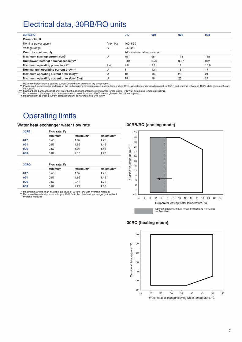
Operating limitsWater heat exchanger water flow rate
30RB Flow rate, l/sMinimum Maximum* Maximum**
017 0.45 1.39 1.26021 0.57 1.52 1.42026 0.67 1.96 1.43033 0.87 2.18 1.72
30RQ Flow rate, l/sMinimum Maximum* Maximum**
017 0.45 1.39 1.26021 0.57 1.52 1.42026 0.67 2.18 1.72033 0.87 2.29 1.85
* Maximum flow rate at an available pressure of 50 kPa (unit with hydronic module) ** Maximum flow rate at pressure drop of 100 kPa in the plate heat exchanger (unit without
hydronic module).
Evaporator leaving water temperature, °C
Out
side
air
tem
pera
ture
, °C
Operating range with anti-freeze solution and Pro-Dialog configuration.
30RB/RQ (cooling mode)
30RQ (heating mode)
-20
-10
0
10
20
30
40
15 20 25 30 35 40 45 50 55
Water heat exchanger leaving water temperature, °C
Out
side
air
tem
pera
ture
, °C
8
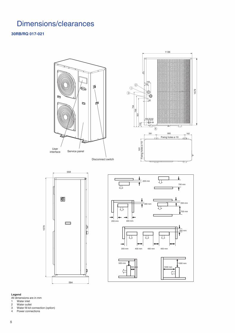
Dimensions/clearances30RB/RQ 017-021
1
3
2150
100
100
82
50 50
100
651
706
794
281 162
200 mm
300 mm
300 mm
200 mm
200 mm
200 mm
200 mm
400 mm
400 mm 400 mm 400 mm
500 mm
700 mm
700 mm
1000 mm
1000 mm
660
522
4
1136
1579
584
1579
559
User interface Service panel
Disconnect switch
Fixing holes ø 10
Fixi
ng h
oles
ø 1
0
LegendAll dimensions are in mm1 Water inlet2 Water outlet3 Water fill kit connection (option)4 Power connections

�
Dimensions/clearances30RB/RQ 026-033
1
2
4
760
1790
824
129 129
1002
153
357
995
170170 460
26314850
35
188
115200 mm 200 mm
200 mm
200 mm
200 mm
400 mm
400 mm
500 mm
500 mm
400 mm1800 mm
710745
3
LegendAll dimensions are in mm1 Water inlet2 Water outlet3 Water fill kit connection (option)4 Power connections
Fixing holes ø 10Fixing holes ø 10
User interface
Service panel
Disconnect switch
10
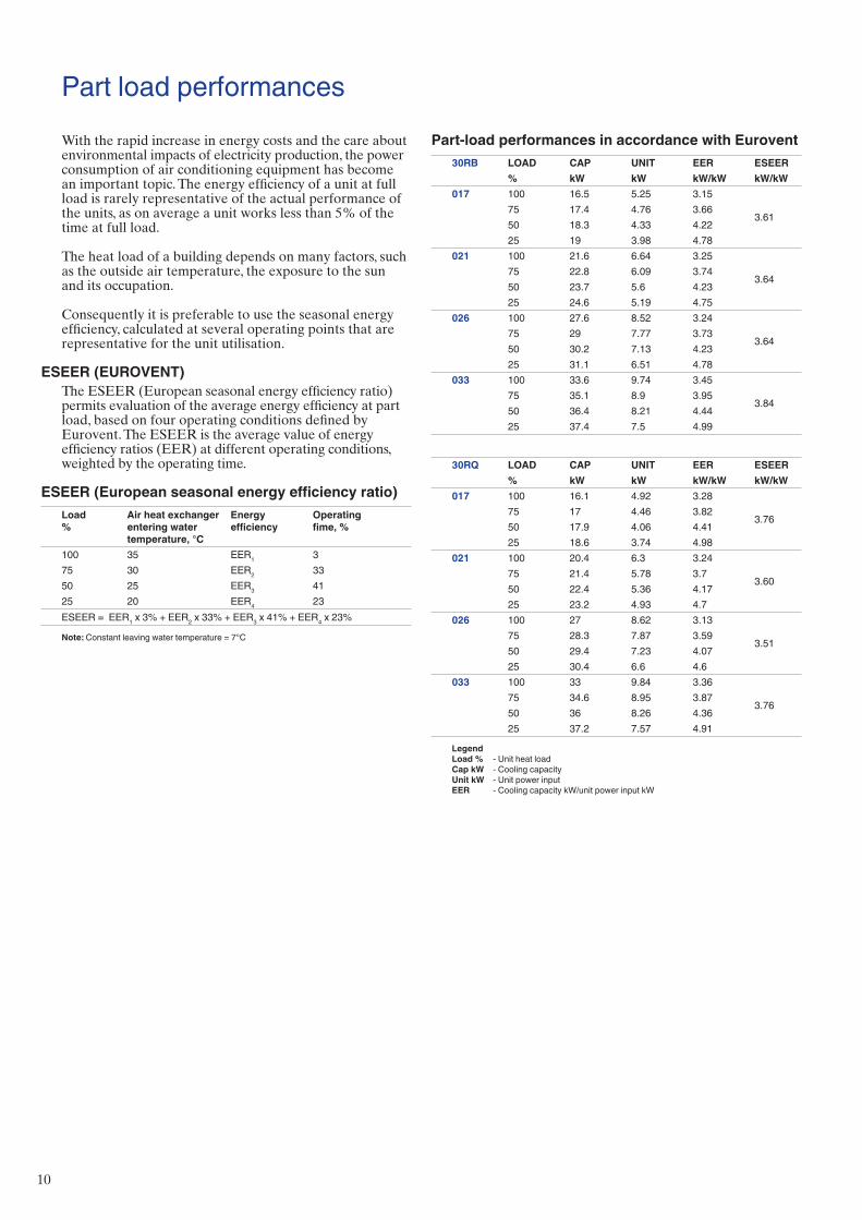
Part load performancesWith the rapid increase in energy costs and the care about environmental impacts of electricity production, the power consumption of air conditioning equipment has become an important topic. The energy efficiency of a unit at full load is rarely representative of the actual performance of the units, as on average a unit works less than 5% of the time at full load.
The heat load of a building depends on many factors, such as the outside air temperature, the exposure to the sun and its occupation.
Consequently it is preferable to use the seasonal energy efficiency, calculated at several operating points that are representative for the unit utilisation.
ESEER (EUROVENT)The ESEER (European seasonal energy efficiency ratio) permits evaluation of the average energy efficiency at part load, based on four operating conditions defined by Eurovent. The ESEER is the average value of energy efficiency ratios (EER) at different operating conditions, weighted by the operating time.
ESEER (European seasonal energy efficiency ratio)Load%
Air heat exchanger entering water temperature, °C
Energy efficiency
Operating fime, %
100 35 EER1 375 30 EER2 3350 25 EER3 4125 20 EER4 23ESEER = EER1 x 3% + EER2 x 33% + EER3 x 41% + EER4 x 23%
Note: Constant leaving water temperature = 7°C
Part-load performances in accordance with Eurovent30RB LOAD CAP UNIT EER ESEER
% kW kW kW/kW kW/kW017 100 16.5 5.25 3.15
3.6175 17.4 4.76 3.6650 18.3 4.33 4.2225 19 3.98 4.78
021 100 21.6 6.64 3.25
3.6475 22.8 6.09 3.7450 23.7 5.6 4.2325 24.6 5.19 4.75
026 100 27.6 8.52 3.24
3.6475 29 7.77 3.7350 30.2 7.13 4.2325 31.1 6.51 4.78
033 100 33.6 9.74 3.45
3.8475 35.1 8.9 3.9550 36.4 8.21 4.4425 37.4 7.5 4.99
30RQ LOAD CAP UNIT EER ESEER% kW kW kW/kW kW/kW
017 100 16.1 4.92 3.28
3.7675 17 4.46 3.8250 17.9 4.06 4.4125 18.6 3.74 4.98
021 100 20.4 6.3 3.24
3.6075 21.4 5.78 3.750 22.4 5.36 4.1725 23.2 4.93 4.7
026 100 27 8.62 3.13
3.5175 28.3 7.87 3.5950 29.4 7.23 4.0725 30.4 6.6 4.6
033 100 33 9.84 3.36
3.7675 34.6 8.95 3.8750 36 8.26 4.3625 37.2 7.57 4.91
Legend Load % - Unit heat load Cap kW - Cooling capacity Unit kW - Unit power input EER - Cooling capacity kW/unit power input kW
11
Le
gend
:
LWT
Leav
ing
wat
er te
mpe
ratu
re
CAP
kW
C
oolin
g ca
paci
ty
CO
MP
kW
Com
pres
sor p
ower
inpu
t
UN
IT k
W
Unit
pow
er in
put (
com
pres
sors
, fan
s an
d co
ntro
l circ
uit)
C
OO
L l/s
Ev
apor
ator
wat
er fl
ow ra
te
CO
OL
kPa
Evap
orat
or p
ress
ure
drop
Ap
plic
atio
n da
ta:
St
anda
rd u
nits
, ref
riger
ant:
R410
A
Evap
orat
or te
mpe
ratu
re ri
se: 5
K
Evap
orat
or fl
uid:
chi
lled
wat
er
Foul
ing
fact
or: 0
.18
x 10
-4 (m
2 K)/W
Pe
rform
ance
s in
acc
orda
nce
with
EN
145
11
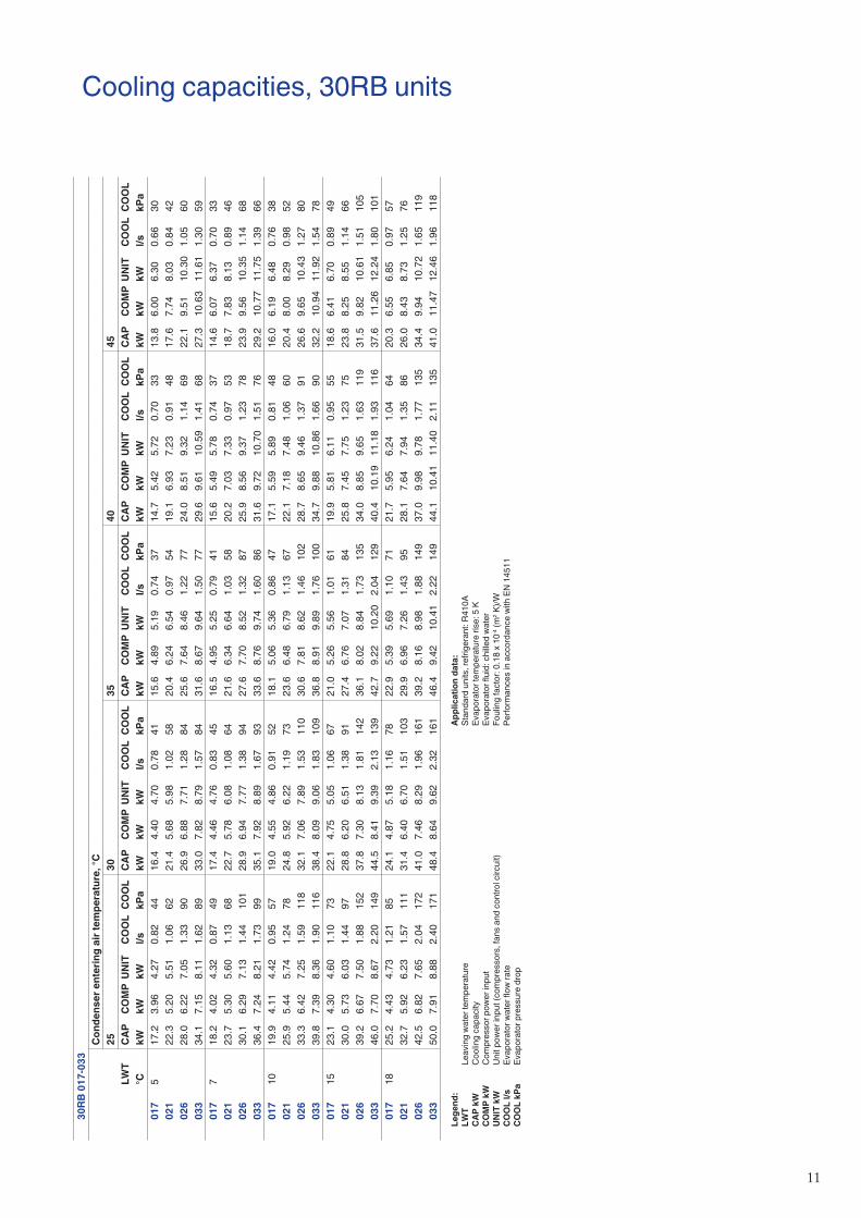
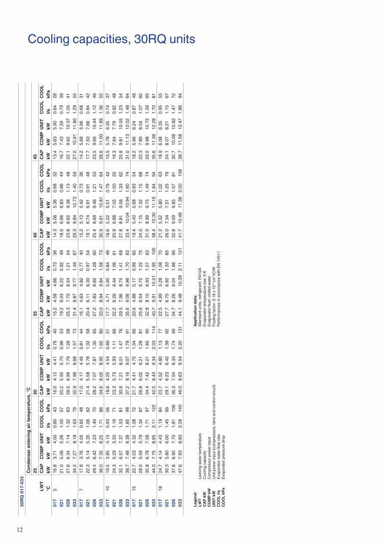
Cooling capacities, 30RB units30
RB 0
17-0
33C
onde
nser
ent
erin
g ai
r tem
pera
ture
, °C
2530
3540
45LW
TC
APC
OM
PU
NIT
CO
OL
CO
OL
CAP
CO
MP
UN
ITC
OO
LC
OO
LC
APC
OM
PU
NIT
CO
OL
CO
OL
CAP
CO
MP
UN
ITC
OO
LC
OO
LC
APC
OM
PU
NIT
CO
OL
CO
OL
°C
kWkW
kWl/s
kPa
kWkW
kWl/s
kPa
kWkW
kWl/s
kPa
kWkW
kWl/s
kPa
kWkW
kWl/s
kPa
017
517
.23.
964.
270.
8244
16.4
4.40
4.70
0.78
4115
.64.
895.
190.
7437
14.7
5.42
5.72
0.70
3313
.86.
006.
300.
6630
021
22.3
5.20
5.51
1.06
6221
.45.
685.
981.
0258
20.4
6.24
6.54
0.97
5419
.16.
937.
230.
9148
17.6
7.74
8.03
0.84
4202
628
.06.
227.
051.
3390
26.9
6.88
7.71
1.28
8425
.67.
648.
461.
2277
24.0
8.51
9.32
1.14
6922
.19.
5110
.30
1.05
6003
334
.17.
158.
111.
6289
33.0
7.82
8.79
1.57
8431
.68.
679.
641.
5077
29.6
9.61
10.5
91.
4168
27.3
10.6
311
.61
1.30
5901
77
18.2
4.02
4.32
0.87
4917
.44.
464.
760.
8345
16.5
4.95
5.25
0.79
4115
.65.
495.
780.
7437
14.6
6.07
6.37
0.70
3302
123
.75.
305.
601.
1368
22.7
5.78
6.08
1.08
6421
.66.
346.
641.
0358
20.2
7.03
7.33
0.97
5318
.77.
838.
130.
8946
026
30.1
6.29
7.13
1.44
101
28.9
6.94
7.77
1.38
9427
.67.
708.
521.
3287
25.9
8.56
9.37
1.23
7823
.99.
5610
.35
1.14
6803
336
.47.
248.
211.
7399
35.1
7.92
8.89
1.67
9333
.68.
769.
741.
6086
31.6
9.72
10.7
01.
5176
29.2
10.7
711
.75
1.39
6601
710
19.9
4.11
4.42
0.95
5719
.04.
554.
860.
9152
18.1
5.06
5.36
0.86
4717
.15.
595.
890.
8148
16.0
6.19
6.48
0.76
3802
125
.95.
445.
741.
2478
24.8
5.92
6.22
1.19
7323
.66.
486.
791.
1367
22.1
7.18
7.48
1.06
6020
.48.
008.
290.
9852
026
33.3
6.42
7.25
1.59
118
32.1
7.06
7.89
1.53
110
30.6
7.81
8.62
1.46
102
28.7
8.65
9.46
1.37
9126
.69.
6510
.43
1.27
8003
339
.87.
398.
361.
9011
638
.48.
099.
061.
8310
936
.88.
919.
891.
7610
034
.79.
8810
.86
1.66
9032
.210
.94
11.9
21.
5478
017
1523
.14.
304.
601.
1073
22.1
4.75
5.05
1.06
6721
.05.
265.
561.
0161
19.9
5.81
6.11
0.95
5518
.66.
416.
700.
8949
021
30.0
5.73
6.03
1.44
9728
.86.
206.
511.
3891
27.4
6.76
7.07
1.31
8425
.87.
457.
751.
2375
23.8
8.25
8.55
1.14
6602
639
.26.
677.
501.
8815
237
.87.
308.
131.
8114
236
.18.
028.
841.
7313
534
.08.
859.
651.
6311
931
.59.
8210
.61
1.51
105
033
46.0
7.70
8.67
2.20
149
44.5
8.41
9.39
2.13
139
42.7
9.22
10.2
02.
0412
940
.410
.19
11.1
81.
9311
637
.611
.26
12.2
41.
8010
101
718
25.2
4.43
4.73
1.21
8524
.14.
875.
181.
1678
22.9
5.39
5.69
1.10
7121
.75.
956.
241.
0464
20.3
6.55
6.85
0.97
5702
132
.75.
926.
231.
5711
131
.46.
406.
701.
5110
329
.96.
967.
261.
4395
28.1
7.64
7.94
1.35
8626
.08.
438.
731.
2576
026
42.5
6.82
7.65
2.04
172
41.0
7.46
8.29
1.96
161
39.2
8.16
8.98
1.88
149
37.0
9.98
9.78
1.77
135
34.4
9.94
10.7
21.
6511
903
350
.07.
918.
882.
4017
148
.48.
649.
622.
3216
146
.49.
4210
.41
2.22
149
44.1
10.4
111
.40
2.11
135
41.0
11.4
712
.46
1.96
118
1�
Cooling capacities, 30RQ units30
RQ 0
17-0
33C
onde
nser
ent
erin
g ai
r tem
pera
ture
, °C
2530
3540
45LW
TC
APC
OM
PU
NIT
CO
OL
CO
OL
CAP
CO
MP
UN
ITC
OO
LC
OO
LC
APC
OM
PU
NIT
CO
OL
CO
OL
CAP
CO
MP
UN
ITC
OO
LC
OO
LC
APC
OM
PU
NIT
CO
OL
CO
OL
°C
kWkW
kWl/s
kPa
kWkW
kWl/s
kPa
kWkW
kWl/s
kPa
kWkW
kWl/s
kPa
kWkW
kWl/s
kPa
017
516
.83.
714.
000.
8043
16.0
4.12
4.41
0.76
4015
.24.
584.
860.
7336
14.3
5.08
5.36
0.68
3213
.45.
635.
900.
6428
021
21.0
5.06
5.26
1.00
5720
.25.
505.
700.
9653
19.2
6.03
6.22
0.92
4918
.06.
666.
830.
8644
16.7
7.43
7.59
0.79
3902
627
.66.
347.
141.
3263
26.5
6.99
7.79
1.26
5825
.37.
758.
541.
2154
23.8
8.62
9.38
1.13
4822
.19.
6210
.37
1.05
4103
334
.27.
278.
181.
6379
32.9
7.98
8.88
1.57
7331
.48.
879.
771.
4967
29.3
9.84
10.7
31.
4059
27.0
10.9
111
.80
1.29
5001
77
17.8
3.76
4.05
0.85
4817
.04.
174.
460.
8144
16.1
4.63
4.92
0.77
4015
.25.
135.
420.
7336
14.2
5.68
5.96
0.68
3102
122
.35.
145.
351.
0662
21.4
5.58
5.78
1.02
5820
.46.
116.
300.
9754
19.1
6.74
6.91
0.91
4817
.77.
507.
660.
8442
026
29.4
6.42
7.23
1.40
7028
.27.
077.
871.
3565
27.0
7.83
8.62
1.28
6025
.48.
699.
461.
2153
23.5
9.69
10.4
41.
1246
033
36.0
7.35
8.25
1.71
8634
.68.
058.
951.
6580
33.0
8.94
9.84
1.58
7330
.99.
9110
.81
1.47
6428
.611
.00
11.8
91.
3655
017
1019
.53.
854.
150.
9356
18.6
4.25
4.54
0.89
5117
.74.
715.
000.
8446
16.6
5.22
5.51
0.79
4215
.55.
786.
050.
7437
021
24.3
5.29
5.50
1.16
7123
.35.
735.
931.
1166
22.2
6.26
6.44
1.06
6120
.96.
887.
051.
0055
19.3
7.64
7.79
0.92
4802
632
.16.
577.
371.
5381
30.9
7.21
8.01
1.47
7629
.57.
968.
741.
4169
27.8
8.81
9.58
1.33
6225
.89.
8110
.55
1.23
5403
338
.77.
488.
381.
8598
37.2
8.16
9.07
1.78
9135
.69.
069.
961.
7083
33.4
10.0
410
.94
1.60
7431
.011
.13
12.0
21.
4864
017
1522
.74.
034.
321.
0872
21.7
4.41
4.70
1.04
6620
.64.
885.
170.
9960
19.4
5.40
5.68
0.93
5418
.25.
966.
240.
8748
021
28.0
5.59
5.79
1.34
8726
.86.
026.
211.
2881
25.6
6.54
6.72
1.22
7524
.07.
157.
321.
1568
22.3
7.89
8.04
1.07
6002
635
.86.
787.
581.
7197
34.4
7.42
8.21
1.65
9032
.88.
158.
931.
5783
31.0
8.99
9.75
1.49
7429
.09.
9810
.72
1.39
6503
344
.07.
758.
652.
1112
242
.58.
439.
342.
0311
440
.79.
3110
.21
1.95
105
38.4
10.3
011
.19
1.84
9435
.611
.39
12.2
81.
7081
017
1824
.74.
144.
431.
1984
23.7
4.52
4.80
1.13
7722
.54.
995.
281.
0870
21.2
5.52
5.80
1.02
6319
.96.
086.
350.
9555
021
30.3
5.80
6.00
1.45
9929
.16.
236.
421.
3992
27.7
6.75
6.92
1.33
8526
.07.
347.
511.
2576
24.1
8.07
8.21
1.15
6702
637
.86.
907.
701.
8110
636
.37.
548.
331.
7499
34.7
8.26
9.04
1.66
9032
.89.
099.
851.
5781
30.7
10.0
810
.82
1.47
7203
347
.67.
938.
832.
2814
046
.08.
639.
542.
2013
144
.19.
4810
.39
2.11
121
41.7
10.4
811
.38
2.00
108
38.7
11.5
812
.47
1.86
94
Le
gend
:
LWT
Leav
ing
wat
er te
mpe
ratu
re
CAP
kW
C
oolin
g ca
paci
ty
CO
MP
kW
Com
pres
sor p
ower
inpu
t
UN
IT k
W
Unit
pow
er in
put (
com
pres
sors
, fan
s an
d co
ntro
l circ
uit)
C
OO
L l/s
Ev
apor
ator
wat
er fl
ow ra
te
CO
OL
kPa
Evap
orat
or p
ress
ure
drop
Ap
plic
atio
n da
ta:
St
anda
rd u
nits
, ref
riger
ant:
R410
A
Evap
orat
or te
mpe
ratu
re ri
se: 5
K
Evap
orat
or fl
uid:
chi
lled
wat
er
Foul
ing
fact
or: 0
.18
x 10
-4 (m
2 K)/W
Pe
rform
ance
s in
acc
orda
nce
with
EN
145
11
13
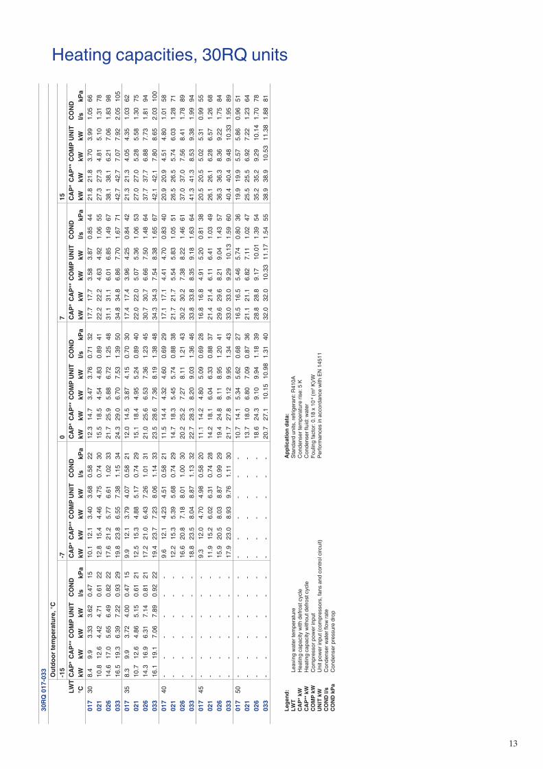
Heating capacities, 30RQ units30
RQ 0
17-0
33 Out
door
tem
pera
ture
, °C
-15
-70
715
LWT
CAP
* C
AP**
CO
MP
UN
ITC
ON
DC
AP*
CAP
** C
OM
PU
NIT
CO
ND
CAP
* C
AP**
CO
MP
UN
ITC
ON
DC
AP*
CAP
** C
OM
PU
NIT
CO
ND
CAP
* C
AP**
CO
MP
UN
ITC
ON
D°C
kW
kWkW
kWl/s
kPa
kWkW
kWkW
l/skP
akW
kWkW
kWl/s
kPa
kWkW
kWkW
l/skP
akW
kWkW
kWl/s
kPa
017
308.
49.
93.
333.
620.
4715
10.1
12.1
3.40
3.68
0.58
2212
.314
.73.
473.
760.
7132
17.7
17.7
3.58
3.87
0.85
4421
.821
.83.
703.
991.
0566
021
10.8
12.6
4.42
4.71
0.61
2212
.815
.44.
464.
750.
7430
15.5
18.5
4.54
4.83
0.89
4122
.222
.24.
634.
921.
0655
27.3
27.3
4.81
5.10
1.31
7802
614
.617
.05.
656.
490.
8222
17.6
21.2
5.77
6.61
1.02
3321
.725
.95.
886.
721.
2548
31.1
31.1
6.01
6.85
1.49
6738
.138
.16.
217.
061.
8398
033
16.5
19.3
6.39
7.22
0.93
2919
.823
.86.
557.
381.
1534
24.3
29.0
6.70
7.53
1.39
5034
.834
.86.
867.
701.
6771
42.7
42.7
7.07
7.92
2.05
105
017
358.
39.
93.
724.
000.
4715
9.9
12.1
3.79
4.07
0.58
2112
.014
.53.
874.
150.
7030
17.4
17.4
3.96
4.25
0.84
4221
.321
.34.
054.
351.
0362
021
10.7
12.6
4.86
5.15
0.61
2112
.515
.34.
885.
170.
7429
15.1
18.4
4.95
5.24
0.89
4022
.022
.05.
075.
361.
0653
27.0
27.0
5.28
5.58
1.30
7502
614
.316
.96.
317.
140.
8121
17.2
21.0
6.43
7.26
1.01
3121
.025
.66.
537.
361.
2345
30.7
30.7
6.66
7.50
1.48
6437
.737
.76.
887.
731.
8194
033
16.1
19.1
7.06
7.89
0.92
2219
.423
.77.
238.
061.
1433
23.5
28.6
7.36
8.19
1.38
4834
.334
.37.
548.
381.
6567
42.1
42.1
7.80
8.65
2.03
100
017
40-
--
--
-9.
612
.14.
234.
510.
5821
11.5
14.4
4.32
4.60
0.69
2917
.117
.14.
414.
700.
8340
20.9
20.9
4.51
4.80
1.01
5802
1-
--
--
-12
.215
.35.
395.
680.
7429
14.7
18.3
5.45
5.74
0.88
3821
.721
.75.
545.
831.
0551
26.5
26.5
5.74
6.03
1.28
7102
6-
--
--
-16
.620
.87.
188.
011.
0030
20.2
25.2
7.27
8.11
1.21
4330
.230
.27.
388.
221.
4661
37.0
37.0
7.56
8.41
1.78
8903
3-
--
--
-18
.823
.58.
048.
871.
1332
22.7
28.3
8.20
9.03
1.36
4633
.833
.88.
359.
181.
6364
41.3
41.3
8.53
9.38
1.99
9401
745
--
--
--
9.3
12.0
4.70
4.98
0.58
2011
.114
.24.
805.
090.
6928
16.8
16.8
4.91
5.20
0.81
3820
.520
.55.
025.
310.
9955
021
--
--
--
11.9
15.2
6.02
6.31
0.74
2814
.218
.16.
046.
330.
8837
21.4
21.4
6.11
6.41
1.03
4926
.126
.16.
286.
571.
2668
026
--
--
--
15.9
20.5
8.03
8.87
0.99
2919
.424
.88.
118.
951.
2041
29.6
29.6
8.21
9.04
1.43
5736
.336
.38.
369.
221.
7584
033
--
--
--
17.9
23.0
8.93
9.76
1.11
3021
.727
.89.
129.
951.
3443
33.0
33.0
9.29
10.1
31.
5960
40.4
40.4
9.48
10.3
31.
9589
017
50-
--
--
--
--
--
-10
.714
.15.
345.
620.
6827
16.5
16.5
5.46
5.74
0.80
3619
.919
.95.
575.
860.
9651
021
--
--
--
--
--
--
13.7
18.0
6.80
7.09
0.87
3621
.121
.16.
827.
111.
0247
25.5
25.5
6.92
7.22
1.23
6402
6-
--
--
--
--
--
-18
.624
.39.
109.
941.
1839
28.8
28.8
9.17
10.0
11.
3954
35.2
35.2
9.29
10.1
41.
7078
033
--
--
--
--
--
--
20.7
27.1
10.1
510
.98
1.31
4032
.032
.010
.33
11.1
71.
5455
38.9
38.9
10.5
311
.38
1.88
81
Le
gend
:
LWT
Leav
ing
wat
er te
mpe
ratu
re
CAP
* kW
H
eatin
g ca
paci
ty w
ith d
efro
st c
ycle
C
AP**
kW
H
eatin
g ca
paci
ty w
ithou
t def
rost
cyc
le
CO
MP
kW
Com
pres
sor p
ower
inpu
t
UN
IT k
W
Unit
pow
er in
put (
com
pres
sors
, fan
s an
d co
ntro
l circ
uit)
C
ON
D l/
s C
onde
nser
wat
er fl
ow ra
te
CO
ND
kPa
C
onde
nser
pre
ssur
e dr
op
Ap
plic
atio
n da
ta:
St
anda
rd u
nits
, ref
riger
ant:
R410
A
Con
dens
er te
mpe
ratu
re ri
se: 5
K
Con
dens
er fl
uid:
wat
er
Foul
ing
fact
or: 0
.18
x 10
-4 (m
2 K)/W
Pe
rform
ance
s in
acc
orda
nce
with
EN
145
11
14
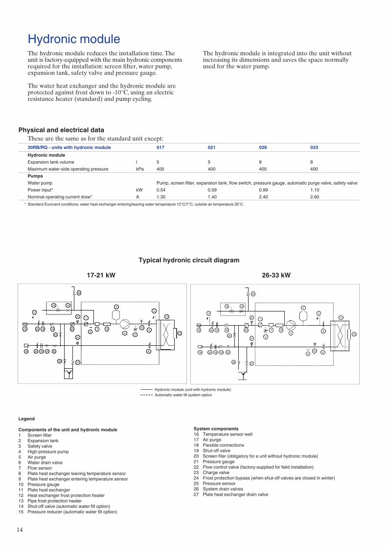
Hydronic module
Typical hydronic circuit diagram
The hydronic module reduces the installation time. The unit is factory-equipped with the main hydronic components required for the installation: screen filter, water pump, expansion tank, safety valve and pressure gauge.
The water heat exchanger and the hydronic module are protected against frost down to -10°C, using an electric resistance heater (standard) and pump cycling.
Physical and electrical dataThese are the same as for the standard unit except:30RB/RQ - units with hydronic module 017 021 026 033Hydronic module Expansion tank volume l 5 5 8 8Maximum water-side operating pressure kPa 400 400 400 400PumpsWater pump Pump, screen filter, expansion tank, flow switch, pressure gauge, automatic purge valve, safety valvePower input* kW 0.54 0.59 0.99 1.10Nominal operating current draw* A 1.30 1.40 2.40 2.60
* Standard Eurovent conditions: water heat exchanger entering/leaving water temperature 12°C/7°C, outside air temperature 35°C.
The hydronic module is integrated into the unit without increasing its dimensions and saves the space normally used for the water pump.
1
2
34
5
67
8
910
11
1213
1415
16
16
17
18
18
20
21
21
22
23
24
25
25
26 27
19
19
1
2
34
5
67
8
910
11
1213
1415
16
16
17
18
18
20
21
21
22
23
24
25
25
26 27
19
19
1
2
34
5
6
7
8
9
10
11
12
13
1415
16
16
17
18
18
20
21
21
22
23
24
25
25
26 27
19
19
1
2
34
5
6
7
8
9
10
11
12
13
1415
16
16
17
18
18
20
21
21
22
23
24
25
25
26 27
19
19
17-21 kW 26-33 kW
Legend
Components of the unit and hydronic module1 Screen filter2 Expansion tank3 Safety valve4 High-pressure pump5 Air purge6 Water drain valve7 Flow sensor8 Plate heat exchanger leaving temperature sensor9 Plate heat exchanger entering temperature sensor10 Pressure gauge11 Plate heat exchanger12 Heat exchanger frost protection heater13 Pipe frost protection heater14 Shut-off valve (automatic water fill option)15 Pressure reducer (automatic water fill option)
Hydronic module (unit with hydronic module)Automatic water fill system option
System components16 Temperature sensor well17 Air purge18 Flexible connections19 Shut-off valve20 Screen fiter (obligatory for a unit without hydronic module)21 Pressure gauge22 Flow control valve (factory-supplied for field installation)23 Charge valve24 Frost protection bypass (when shut-off valves are closed in winter)25 Pressure sensor26 System drain valves27 Plate heat exchanger drain valve
15
60
80
100
120
140
160
180
200
220
240
260
280
300
0 0,5 1,0 1,5 2,0 2,5
1 2 3 4 5
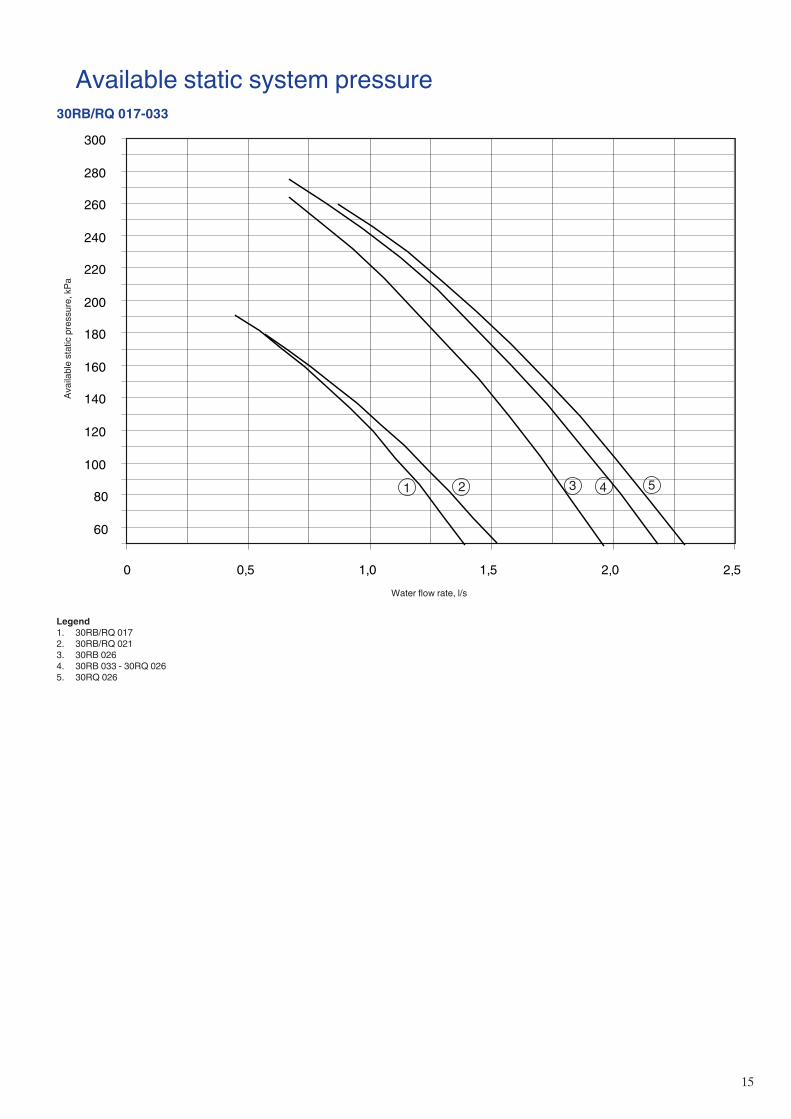
Available static system pressure30RB/RQ 017-033
Avai
labl
e st
atic
pre
ssur
e, k
Pa
Water flow rate, l/s
Legend1. 30RB/RQ 0172. 30RB/RQ 0213. 30RB 0264. 30RB 033 - 30RQ 0265. 30RQ 026

Order No.: 13463-20.06.2009. Supersedes order No.: New. Manufactured by: Carrier SpA, Villasanta, Italy.Manufacturer reserves the right to change any product specifications without notice. Printed in the Netherlands.
Carrier is participating in the Eurovent Certification Programme for liquid chilling packages. Products are as listed in the Eurovent
Directory of Certified Products or on the Internet site www.eurovent-certification.com.
This programme covers air-cooled chillers up to 600 kW and water-cooled chillers up to 1500 kW.
Environmental Management
Systems